US10630317B2 - Method for performing error corrections of digital information codified as a symbol sequence - Google Patents
Method for performing error corrections of digital information codified as a symbol sequenceDownload PDFInfo
- Publication number
- US10630317B2 US10630317B2US14/609,326US201514609326AUS10630317B2US 10630317 B2US10630317 B2US 10630317B2US 201514609326 AUS201514609326 AUS 201514609326AUS 10630317 B2US10630317 B2US 10630317B2
- Authority
- US
- United States
- Prior art keywords
- error
- type
- binary
- code
- value
- Prior art date
- Legal status (The legal status is an assumption and is not a legal conclusion. Google has not performed a legal analysis and makes no representation as to the accuracy of the status listed.)
- Expired - Lifetime
Links
- 238000000034methodMethods0.000titleclaimsabstractdescription24
- 238000012937correctionMethods0.000titleclaimsabstractdescription13
- 239000011159matrix materialSubstances0.000claimsabstractdescription82
- 208000011580syndromic diseaseDiseases0.000claimsabstractdescription16
- 239000013598vectorSubstances0.000claimsdescription19
- 238000004891communicationMethods0.000claimsdescription14
- 238000001514detection methodMethods0.000claimsdescription9
- 239000000654additiveSubstances0.000claimsdescription5
- 230000000996additive effectEffects0.000claimsdescription5
- 230000005540biological transmissionEffects0.000abstractdescription4
- 230000009897systematic effectEffects0.000description5
- 238000010586diagramMethods0.000description3
- 230000000295complement effectEffects0.000description2
- 241001086438Euclichthys polynemusSpecies0.000description1
- 230000008094contradictory effectEffects0.000description1
- 230000001419dependent effectEffects0.000description1
- 238000011161developmentMethods0.000description1
- 238000004519manufacturing processMethods0.000description1
- 238000012986modificationMethods0.000description1
- 230000004048modificationEffects0.000description1
- 239000000126substanceSubstances0.000description1
Images


Classifications
- H—ELECTRICITY
- H03—ELECTRONIC CIRCUITRY
- H03M—CODING; DECODING; CODE CONVERSION IN GENERAL
- H03M13/00—Coding, decoding or code conversion, for error detection or error correction; Coding theory basic assumptions; Coding bounds; Error probability evaluation methods; Channel models; Simulation or testing of codes
- H03M13/03—Error detection or forward error correction by redundancy in data representation, i.e. code words containing more digits than the source words
- H03M13/05—Error detection or forward error correction by redundancy in data representation, i.e. code words containing more digits than the source words using block codes, i.e. a predetermined number of check bits joined to a predetermined number of information bits
- H03M13/13—Linear codes
- H03M13/15—Cyclic codes, i.e. cyclic shifts of codewords produce other codewords, e.g. codes defined by a generator polynomial, Bose-Chaudhuri-Hocquenghem [BCH] codes
- H03M13/151—Cyclic codes, i.e. cyclic shifts of codewords produce other codewords, e.g. codes defined by a generator polynomial, Bose-Chaudhuri-Hocquenghem [BCH] codes using error location or error correction polynomials
- H03M13/1575—Direct decoding, e.g. by a direct determination of the error locator polynomial from syndromes and subsequent analysis or by matrix operations involving syndromes, e.g. for codes with a small minimum Hamming distance
- H—ELECTRICITY
- H03—ELECTRONIC CIRCUITRY
- H03M—CODING; DECODING; CODE CONVERSION IN GENERAL
- H03M13/00—Coding, decoding or code conversion, for error detection or error correction; Coding theory basic assumptions; Coding bounds; Error probability evaluation methods; Channel models; Simulation or testing of codes
- H03M13/03—Error detection or forward error correction by redundancy in data representation, i.e. code words containing more digits than the source words
- H03M13/05—Error detection or forward error correction by redundancy in data representation, i.e. code words containing more digits than the source words using block codes, i.e. a predetermined number of check bits joined to a predetermined number of information bits
- H03M13/13—Linear codes
- H03M13/15—Cyclic codes, i.e. cyclic shifts of codewords produce other codewords, e.g. codes defined by a generator polynomial, Bose-Chaudhuri-Hocquenghem [BCH] codes
- H—ELECTRICITY
- H03—ELECTRONIC CIRCUITRY
- H03M—CODING; DECODING; CODE CONVERSION IN GENERAL
- H03M13/00—Coding, decoding or code conversion, for error detection or error correction; Coding theory basic assumptions; Coding bounds; Error probability evaluation methods; Channel models; Simulation or testing of codes
- H03M13/03—Error detection or forward error correction by redundancy in data representation, i.e. code words containing more digits than the source words
- H03M13/05—Error detection or forward error correction by redundancy in data representation, i.e. code words containing more digits than the source words using block codes, i.e. a predetermined number of check bits joined to a predetermined number of information bits
- H03M13/13—Linear codes
- H03M13/19—Single error correction without using particular properties of the cyclic codes, e.g. Hamming codes, extended or generalised Hamming codes
Definitions
- embodiments of the present inventionrelate to methods and systems for applying the self-corrector code theory to digital information coded as symbol sequences, for example in the Boolean logic, stored in electronic memory systems or transmitted from and to these systems.
- an embodiment of the inventionrelates to a method as above providing the transmission of sequences incorporating a portion of error corrector code allowing the sequence, which is more probably the original transmitted through the calculation of an error syndrome by using a parity matrix, to be restored when received.
- any message C comprising digital informationcan be processed and transferred from a system to another through electronic communication means which might be affected by noise.
- a sequence x of Boolean symbols by a transmitter 102 through a communication channel 104 undergoing noisecan be received at a receiver 106 as a different sequence y from which it is necessary to go back to the initial sequence x.
- the sequence x of symbols to be transmittedcomprises an additional or redundant portion including an error corrector code allowing the message, which is more probably the original even with errors, to be restored when received.
- error corrector codesare based on well known mathematical theories, such as for example the Hamming code theory, which are presently applied in several contexts wherein it is necessary to remedy noise in communication channels.
- n-x-n-order square matrix Mis considered. Fixing an element a ik of the matrix M and eliminating therein the row and the column crossing in the element (the i-th row and the k-th column) a square matrix of order (n ⁇ 1) ⁇ (n ⁇ 1) is obtained, whose determinant is called complementary minor of a ik and will be indicated with M ik .
- a group Gis a set in which an operation * is defined, for which G is closed for *, i.e. if g ⁇ G and h ⁇ G g*h ⁇ G;
- Definition 9A group is called abelian if the operation * is commutative.
- a family of vectorsis called base of the area if it is a generating family, i.e. any other vector of the area is a linear combination of these vectors, and it is composed of linearly independent vectors.
- a messageis considered as a block of symbols of a finite alphabet; it is usually a sequence of 0 and 1 but it can be also any number, a letter or a complete sentence.
- the messageis transmitted through a communication channel undergoing a noise.
- the aim of the self-corrector code theoryis to add redundant terms to the message so that it is possible to go back to the original message if the transmitted message has been damaged.
- a differencemust be made between diagnosing and correcting errors. Diagnostics detects the presence of an error, while the correction detects and corrects the error.
- Each message called cconsists of k information digits.
- the codingturns, according to certain rules, each input message c into a binary nth number x with n>k.
- This binary nth number xis the code word of the message c. During the transmission some errors can occur, the binary nth number y being thus received c ⁇ x ⁇ channel ⁇ y
- a linear binary code [n,k]is the set of all linear combinations of k( ⁇ 0) independent vectors in V.
- Linearmeans that if two or more vectors are in the code, also their sum is therein.
- a generating matrix G for a linear codeis a matrix k x n whose rows are a base for C.
- Systematic codeshave the advantage that the data message is in the code word and it can be read before decoding.
- codes in the non-systematic formthe message is no more recognizable in the coded sequence and an inverter is needed to recognize the data sequence.
- Definition 20Being C a linear code with parity matrix H, then, given x a binary nth number xH T , is called syndrome of x.
- the code minimum weight dis the weight of the vector different from 0 having the lowest weight in the code.
- dis thus a measure of the “quality” of a code.
- Corollary 24 Chas a minimum weight d if d is the highest number so that each d-1 columns of the parity matrix H are independent.
- the matrix Hwill be composed of the identity matrix and of a matrix P T having 4 linearly independent columns, i.e. so that the determinant of the sub-matrix composed of these four columns ⁇ 0. Therefore, according to the number of errors to be corrected, a matrix H with d-1 linearly independent columns is searched. Therefore, given n and k, a code with d being the widest possible is searched in order to correct more errors.
- a minimum-weight-d code Cis called perfect if all vectors in V are comprised in spheres of radius
- the idealis thus to search perfect codes, but they are not always found, moreover codes recognizing an error of the 0 ⁇ 1 type from 1 ⁇ 0 are wished.
- a technical problem underlying embodiments of the present inventionis to provide a linear code protecting digital information coded like binary symbol sequences and overcoming the limits of the solutions presently provided by the prior art.
- a codingis identified for a binary alphabet in non Boolean groups, i.e. in non binary groups.
- FIG. 1is a block diagram of a conventional communication system including error detection and correction.
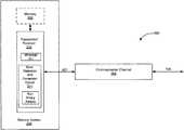
- FIG. 2is a block diagram of a communication system including error detection and correction circuitry according to one embodiment of the present invention.
- FIG. 2is a block diagram of a communication system 200 including error detection and correction circuitry 201 for executing a method according to an embodiment of the invention. This method applies self-corrector code theory to digital information coded as symbol sequences.
- the system 200further includes a transmitter/receiver 202 that operate in conjunction with the circuitry 201 to transmit messages X and receive messages Y over and a communications channel 204 .
- a methodallows error corrections to be performed on digital information coded as symbol sequences x, for example digital information stored in electronic memory systems or transmitted from and to these systems and providing the transmission of sequences x incorporating an error corrector code portion allowing the sequence x, which is more probably the original transmitted through the calculation of an error syndrome using a parity matrix, to be restored when received.
- FIG. 2functionally illustrates such a memory system 206 including a memory 208 and the transmitter/receiver 202 .
- the methodprovides that the error code incorporated in the original sequence x belongs to a non Boolean group.
- error code usedis a linear code, as it will be apparent from the following detailed description of the method embodiments.
- Additive groupsare considered.
- Now additive groupsare considered (mod p) with p ⁇ N.
- the identity matrixis composed of the numbers p-1, p-2, . . . , p-2 n ⁇ k .
- the binary-written matrixwill then have the form:
- I 2( 1 0 0 1 1 0 1 1 ) opposite to the usual identity matrix
- I 1( 1 0 0 0 1 0 0 0 1 ) represented by the 10-based numbers: 1, 2 and 4
- any matrixcould be chosen, having a “determinant” ⁇ 0, i.e. a number belonging to that matrix is not a linear combination of other numbers belonging to that matrix. This choice is particularly effective. It can be seen with an example.
- the numbers composing the parity matrix P columnsmust be chosen according to similar criteria to those of the Boolean group.
- An error +1is allocated to the first case and an error ⁇ 1 to the second case.
- the second code wordis sent, but 111110 is received, i.e. an error +1 has occurred in the fourth position.
- the errors in the message receivedcan be only of one type, or +1 or ⁇ 1 in each position, if the corresponding bit is 0 or 1 in the message received. If an impossible error is detected, it means that the code could diagnose but not correct the errors.
- the code wordswill be: 0
- the word 000is sent, all errors which may occur and the decoding are considered.
- the word 111is now sent, all errors which may occur and the decoding are considered.
- error correcting code methodology described hereinmay be utilized in a variety of different types of electronic systems, such as communications, digital video, memory and computer systems, as will be appreciated by those skilled in the art.
Landscapes
- Physics & Mathematics (AREA)
- Probability & Statistics with Applications (AREA)
- Engineering & Computer Science (AREA)
- Theoretical Computer Science (AREA)
- Mathematical Physics (AREA)
- Algebra (AREA)
- General Physics & Mathematics (AREA)
- Pure & Applied Mathematics (AREA)
- Error Detection And Correction (AREA)
- Detection And Prevention Of Errors In Transmission (AREA)
Abstract
Description
obtained from M by exchanging, in order, rows with columns.

c→x→channel→y
errors and vice versa.
around the code words. In this case it can be said that the spheres cover the area. For the given n and k they are the best codes.
Generally,
m+xi
Hxi∈H?→wrong position: i
m+xi+xj
∀xi→Hxi+Hxj∈H?→wrong positions: i and j
(1011010). The parity matrix H is considered:
HyT=(100)
(1 0 0) is the binary representation of 4; the wrong bit is therefore the fourth.
y·HT=0
if y is a code word. Linear codes are thus searched. Moreover if y is affected by one or more errors, it results:
(y+ξi+ξj)·HT=ξi·HT·ξj·HT=si+sj
where siand sjare the i-th and j-th columns of the matrix HT. The code being searched must therefore belong to an Abelian group to have this property.
2n−k+1≤p≤2n−k+1−1
opposite to the usual identity matrix
represented by the 10-based numbers: 1, 2 and 4
1+mn−k·1=0(mod p)
[1,2,4](c1c2c3)+1=0
[7,6,4](c1c2c3)+1=0
H=(11|21 20 18 14 6)
In binary this matrix will be:
0|00000
1|11010
0|00 1|0
(010)·H=3
3 is in the matrix and this would indicate an error +1 in the second position. 4−3=1 is also in the matrix and this would indicate an error −1 in the first position. In fact 010 can be obtained also from 110 with an error in the first position. Therefore a code cannot be found on Z4. Sometimes, in order to correct the errors, it is necessary not only to calculate the syndrome but also to compare the bits received. A code [3,1] is considered on Z5with matrix H=(3|43). The code words will be:
0|00 1|1
- 1) −1 in the first position;
- 2) −1 in the third position;
- 1) −1 in the first position;
- 2) −1 in the third position;
Claims (16)
Priority Applications (1)
| Application Number | Priority Date | Filing Date | Title |
|---|---|---|---|
| US14/609,326US10630317B2 (en) | 2003-03-19 | 2015-01-29 | Method for performing error corrections of digital information codified as a symbol sequence |
Applications Claiming Priority (6)
| Application Number | Priority Date | Filing Date | Title |
|---|---|---|---|
| EP03425172AEP1460765A1 (en) | 2003-03-19 | 2003-03-19 | Method for performing error corrections of digital information codified as a symbol sequence |
| EP03425172 | 2003-03-19 | ||
| EP03425172.8 | 2003-03-19 | ||
| US10/805,168US7328397B2 (en) | 2003-03-19 | 2004-03-19 | Method for performing error corrections of digital information codified as a symbol sequence |
| US12/001,294US8966335B2 (en) | 2003-03-19 | 2007-12-10 | Method for performing error corrections of digital information codified as a symbol sequence |
| US14/609,326US10630317B2 (en) | 2003-03-19 | 2015-01-29 | Method for performing error corrections of digital information codified as a symbol sequence |
Related Parent Applications (1)
| Application Number | Title | Priority Date | Filing Date |
|---|---|---|---|
| US12/001,294ContinuationUS8966335B2 (en) | 2003-03-19 | 2007-12-10 | Method for performing error corrections of digital information codified as a symbol sequence |
Publications (2)
| Publication Number | Publication Date |
|---|---|
| US20150143206A1 US20150143206A1 (en) | 2015-05-21 |
| US10630317B2true US10630317B2 (en) | 2020-04-21 |
Family
ID=32799219
Family Applications (3)
| Application Number | Title | Priority Date | Filing Date |
|---|---|---|---|
| US10/805,168Expired - LifetimeUS7328397B2 (en) | 2003-03-19 | 2004-03-19 | Method for performing error corrections of digital information codified as a symbol sequence |
| US12/001,294Active2027-03-31US8966335B2 (en) | 2003-03-19 | 2007-12-10 | Method for performing error corrections of digital information codified as a symbol sequence |
| US14/609,326Expired - LifetimeUS10630317B2 (en) | 2003-03-19 | 2015-01-29 | Method for performing error corrections of digital information codified as a symbol sequence |
Family Applications Before (2)
| Application Number | Title | Priority Date | Filing Date |
|---|---|---|---|
| US10/805,168Expired - LifetimeUS7328397B2 (en) | 2003-03-19 | 2004-03-19 | Method for performing error corrections of digital information codified as a symbol sequence |
| US12/001,294Active2027-03-31US8966335B2 (en) | 2003-03-19 | 2007-12-10 | Method for performing error corrections of digital information codified as a symbol sequence |
Country Status (2)
| Country | Link |
|---|---|
| US (3) | US7328397B2 (en) |
| EP (1) | EP1460765A1 (en) |
Families Citing this family (21)
| Publication number | Priority date | Publication date | Assignee | Title |
|---|---|---|---|---|
| EP1460765A1 (en) | 2003-03-19 | 2004-09-22 | STMicroelectronics S.r.l. | Method for performing error corrections of digital information codified as a symbol sequence |
| US7071849B2 (en)* | 2004-04-04 | 2006-07-04 | Guobiao Zhang | Fractional-Bit Systems |
| US7167109B2 (en)* | 2005-03-31 | 2007-01-23 | Chenming Hu | Hybrid fractional-bit systems |
| US7633128B2 (en)* | 2005-07-15 | 2009-12-15 | Guobiao Zhang | N-ary mask-programmable memory |
| US7821080B2 (en)* | 2005-07-15 | 2010-10-26 | Guobiao Zhang | N-ary three-dimensional mask-programmable read-only memory |
| US7797611B2 (en)* | 2005-11-14 | 2010-09-14 | International Business Machines Corporation | Creating an error correction coding scheme and reducing data loss |
| US8405488B1 (en) | 2008-10-21 | 2013-03-26 | Universal Lighting Technologies, Inc. | System and method for encoding ballast control signals |
| US8564070B2 (en) | 2010-05-24 | 2013-10-22 | Chengdu Haicun Ip Technology Llc | Large bit-per-cell three-dimensional mask-programmable read-only memory |
| US10148285B1 (en) | 2012-07-25 | 2018-12-04 | Erich Schmitt | Abstraction and de-abstraction of a digital data stream |
| RU2530289C1 (en)* | 2013-02-12 | 2014-10-10 | Владимир Петрович Панов | Information transmission and reception method |
| US10795858B1 (en) | 2014-02-18 | 2020-10-06 | Erich Schmitt | Universal abstraction and de-abstraction of a digital data stream |
| US11086716B2 (en) | 2019-07-24 | 2021-08-10 | Microchip Technology Inc. | Memory controller and method for decoding memory devices with early hard-decode exit |
| US12175363B2 (en) | 2020-07-27 | 2024-12-24 | Microchip Technology Inc. | Regression neural network for identifying threshold voltages to be used in reads of flash memory devices |
| US12393846B2 (en) | 2020-08-20 | 2025-08-19 | Microchip Technology Inc. | Partitionable neural network for solid state drives |
| US11398291B2 (en) | 2020-11-20 | 2022-07-26 | Microchip Technology Inc. | Method and apparatus for determining when actual wear of a flash memory device differs from reliability states for the flash memory device |
| US11514992B2 (en) | 2021-02-25 | 2022-11-29 | Microchip Technology Inc. | Method and apparatus for reading a flash memory device |
| US11934696B2 (en) | 2021-05-18 | 2024-03-19 | Microchip Technology Inc. | Machine learning assisted quality of service (QoS) for solid state drives |
| US11699493B2 (en) | 2021-05-24 | 2023-07-11 | Microchip Technology Inc. | Method and apparatus for performing a read of a flash memory using predicted retention-and-read-disturb-compensated threshold voltage shift offset values |
| US11514994B1 (en) | 2021-05-28 | 2022-11-29 | Microchip Technology Inc. | Method and apparatus for outlier management |
| US11663076B2 (en) | 2021-06-01 | 2023-05-30 | Microchip Technology Inc. | Memory address protection |
| DE112022002131T5 (en) | 2021-09-28 | 2024-04-11 | Microchip Technology Inc. | LDPC DECODING WITH TRAPPED BLOCK MANAGEMENT |
Citations (32)
| Publication number | Priority date | Publication date | Assignee | Title |
|---|---|---|---|---|
| US4312069A (en) | 1980-02-07 | 1982-01-19 | Bell Telephone Laboratories, Incorporated | Serial encoding-decoding for cyclic block codes |
| US4359772A (en)* | 1980-11-14 | 1982-11-16 | International Business Machines Corporation | Dual function error correcting system |
| US4607367A (en) | 1983-07-19 | 1986-08-19 | Sony Corporation | Correcting errors in binary data |
| US5343426A (en) | 1992-06-11 | 1994-08-30 | Digital Equipment Corporation | Data formater/converter for use with solid-state disk memory using storage devices with defects |
| US5459742A (en) | 1992-06-11 | 1995-10-17 | Quantum Corporation | Solid state disk memory using storage devices with defects |
| US5537427A (en)* | 1991-08-21 | 1996-07-16 | International Business Machines Corporation | Modular multiple error correcting code system |
| US5644695A (en)* | 1994-01-03 | 1997-07-01 | International Business Machines Corporation | Array combinatorial decoding with multiple error and erasure detection and location using cyclic equivalence testing |
| US5691994A (en) | 1995-05-08 | 1997-11-25 | Western Digital Corporation | Disk drive with fast error correction validation |
| US5710783A (en) | 1995-06-07 | 1998-01-20 | Luthi; Daniel A. | Optimization of synchronization control in concatenated decoders |
| US5757671A (en)* | 1995-08-03 | 1998-05-26 | Centre National De La Recherche Scientifique | Multi-detector ellipsometer and process of multi-detector ellipsometric measurement |
| US5978952A (en)* | 1996-12-31 | 1999-11-02 | Intel Corporation | Time-distributed ECC scrubbing to correct memory errors |
| US6041430A (en)* | 1997-11-03 | 2000-03-21 | Sun Microsystems, Inc. | Error detection and correction code for data and check code fields |
| US6044483A (en)* | 1998-01-29 | 2000-03-28 | International Business Machines Corporation | Error propagation operating mode for error correcting code retrofit apparatus |
| US6275965B1 (en) | 1997-11-17 | 2001-08-14 | International Business Machines Corporation | Method and apparatus for efficient error detection and correction in long byte strings using generalized, integrated, interleaved reed-solomon codewords |
| US20020051501A1 (en) | 2000-04-28 | 2002-05-02 | Victor Demjanenko | Use of turbo-like codes for QAM modulation using independent I and Q decoding techniques and applications to xDSL systems |
| US20020120901A1 (en)* | 1999-07-30 | 2002-08-29 | Poirier Christopher A. | Early error detection using ECC |
| US20020188906A1 (en) | 2001-06-06 | 2002-12-12 | Kurtas Erozan M. | Method and coding apparatus using low density parity check codes for data storage or data transmission |
| US6516443B1 (en)* | 2000-02-08 | 2003-02-04 | Cirrus Logic, Incorporated | Error detection convolution code and post processor for correcting dominant error events of a trellis sequence detector in a sampled amplitude read channel for disk storage systems |
| US20030066020A1 (en) | 2001-06-11 | 2003-04-03 | Fujitsu Limited | Recording and reproducing apparatus, signal decoding circuit, error correction method and iterative decoder |
| US6675349B1 (en)* | 2000-05-11 | 2004-01-06 | International Business Machines Corporation | Error correction coding of data blocks with included parity bits |
| US6732325B1 (en)* | 2000-11-08 | 2004-05-04 | Digeo, Inc. | Error-correction with limited working storage |
| US20040133836A1 (en) | 2003-01-07 | 2004-07-08 | Emrys Williams | Method and apparatus for performing error correction code (ECC) conversion |
| US6915446B2 (en) | 2001-09-29 | 2005-07-05 | Hewlett-Packard Development Company, L.P. | Supporting error correction and improving error detection dynamically on the PCI-X bus |
| US20050219080A1 (en) | 2002-06-17 | 2005-10-06 | Koninklijke Philips Electronics N.V. | Lossless data embedding |
| US7010738B2 (en) | 2001-03-09 | 2006-03-07 | International Business Machines Corporation | Combinational circuit, and encoder, decoder and semiconductor device using this combinational circuit |
| US7181677B1 (en) | 2003-02-10 | 2007-02-20 | Maxtor Corporation | System and method for producing data and ECC code words using a high rate restricted-symbol code |
| US7188294B2 (en)* | 2001-10-05 | 2007-03-06 | Stmicroelectronics S.A. | High-efficiency error detection and/or correction code |
| US7278085B1 (en) | 2003-03-06 | 2007-10-02 | Maxtor Corporation | Simple error-correction codes for data buffers |
| US20080104477A1 (en) | 2003-03-19 | 2008-05-01 | Stmicroelectronics S.R.I. | Method for performing error corrections of digital information codified as a symbol sequence |
| US20100031440A1 (en) | 2008-08-11 | 2010-02-11 | Lawrence Harrow | Bed base |
| US20100058151A1 (en)* | 2008-08-26 | 2010-03-04 | Spansion Llc | Implementation of recycling unused ecc parity bits during flash memory programming |
| US7949931B2 (en)* | 2007-01-02 | 2011-05-24 | International Business Machines Corporation | Systems and methods for error detection in a memory system |
Family Cites Families (11)
| Publication number | Priority date | Publication date | Assignee | Title |
|---|---|---|---|---|
| US3665396A (en)* | 1968-10-11 | 1972-05-23 | Codex Corp | Sequential decoding |
| FR2533091A1 (en)* | 1982-09-13 | 1984-03-16 | Cii Honeywell Bull | SYSTEM FOR DETECTING AND CORRECTING TRANSMISSION ERRORS OF A BINARY MESSAGE USING A CYCLIC CODE DETECTOR AND CORRECTING ERRORS OF THE REED-SOLOMON TYPE BETWEEN |
| US4841300A (en)* | 1986-06-18 | 1989-06-20 | Mitsubishi Denki K.K. | Error correction encoder/decoder |
| US5040179A (en)* | 1989-08-18 | 1991-08-13 | Loral Aerospace Corp. | High data rate BCH encoder |
| ATE116081T1 (en)* | 1989-08-24 | 1995-01-15 | Philips Nv | METHOD AND DEVICE FOR DECODING PROTECTED CODE WORDS BY A NON-BINARY BCH CODE AGAINST AT LEAST ONE SYMBOL ERROR. |
| US5343481A (en)* | 1991-01-07 | 1994-08-30 | Kraft Clifford H | BCH error-location polynomial decoder |
| US5389835A (en)* | 1991-04-12 | 1995-02-14 | Hewlett-Packard Company | Vector logic method and dynamic mousetrap logic gate for a self-timed monotonic logic progression |
| US5754753A (en)* | 1992-06-11 | 1998-05-19 | Digital Equipment Corporation | Multiple-bit error correction in computer main memory |
| US5884304A (en)* | 1996-09-20 | 1999-03-16 | Novell, Inc. | Alternate key index query apparatus and method |
| US6092233A (en)* | 1998-03-20 | 2000-07-18 | Adaptec, Inc. | Pipelined Berlekamp-Massey error locator polynomial generating apparatus and method |
| JP3830683B2 (en)* | 1998-12-28 | 2006-10-04 | 富士通株式会社 | VLIW processor |
- 2003
- 2003-03-19EPEP03425172Apatent/EP1460765A1/ennot_activeWithdrawn
- 2004
- 2004-03-19USUS10/805,168patent/US7328397B2/ennot_activeExpired - Lifetime
- 2007
- 2007-12-10USUS12/001,294patent/US8966335B2/enactiveActive
- 2015
- 2015-01-29USUS14/609,326patent/US10630317B2/ennot_activeExpired - Lifetime
Patent Citations (32)
| Publication number | Priority date | Publication date | Assignee | Title |
|---|---|---|---|---|
| US4312069A (en) | 1980-02-07 | 1982-01-19 | Bell Telephone Laboratories, Incorporated | Serial encoding-decoding for cyclic block codes |
| US4359772A (en)* | 1980-11-14 | 1982-11-16 | International Business Machines Corporation | Dual function error correcting system |
| US4607367A (en) | 1983-07-19 | 1986-08-19 | Sony Corporation | Correcting errors in binary data |
| US5537427A (en)* | 1991-08-21 | 1996-07-16 | International Business Machines Corporation | Modular multiple error correcting code system |
| US5343426A (en) | 1992-06-11 | 1994-08-30 | Digital Equipment Corporation | Data formater/converter for use with solid-state disk memory using storage devices with defects |
| US5459742A (en) | 1992-06-11 | 1995-10-17 | Quantum Corporation | Solid state disk memory using storage devices with defects |
| US5644695A (en)* | 1994-01-03 | 1997-07-01 | International Business Machines Corporation | Array combinatorial decoding with multiple error and erasure detection and location using cyclic equivalence testing |
| US5691994A (en) | 1995-05-08 | 1997-11-25 | Western Digital Corporation | Disk drive with fast error correction validation |
| US5710783A (en) | 1995-06-07 | 1998-01-20 | Luthi; Daniel A. | Optimization of synchronization control in concatenated decoders |
| US5757671A (en)* | 1995-08-03 | 1998-05-26 | Centre National De La Recherche Scientifique | Multi-detector ellipsometer and process of multi-detector ellipsometric measurement |
| US5978952A (en)* | 1996-12-31 | 1999-11-02 | Intel Corporation | Time-distributed ECC scrubbing to correct memory errors |
| US6041430A (en)* | 1997-11-03 | 2000-03-21 | Sun Microsystems, Inc. | Error detection and correction code for data and check code fields |
| US6275965B1 (en) | 1997-11-17 | 2001-08-14 | International Business Machines Corporation | Method and apparatus for efficient error detection and correction in long byte strings using generalized, integrated, interleaved reed-solomon codewords |
| US6044483A (en)* | 1998-01-29 | 2000-03-28 | International Business Machines Corporation | Error propagation operating mode for error correcting code retrofit apparatus |
| US20020120901A1 (en)* | 1999-07-30 | 2002-08-29 | Poirier Christopher A. | Early error detection using ECC |
| US6516443B1 (en)* | 2000-02-08 | 2003-02-04 | Cirrus Logic, Incorporated | Error detection convolution code and post processor for correcting dominant error events of a trellis sequence detector in a sampled amplitude read channel for disk storage systems |
| US20020051501A1 (en) | 2000-04-28 | 2002-05-02 | Victor Demjanenko | Use of turbo-like codes for QAM modulation using independent I and Q decoding techniques and applications to xDSL systems |
| US6675349B1 (en)* | 2000-05-11 | 2004-01-06 | International Business Machines Corporation | Error correction coding of data blocks with included parity bits |
| US6732325B1 (en)* | 2000-11-08 | 2004-05-04 | Digeo, Inc. | Error-correction with limited working storage |
| US7010738B2 (en) | 2001-03-09 | 2006-03-07 | International Business Machines Corporation | Combinational circuit, and encoder, decoder and semiconductor device using this combinational circuit |
| US20020188906A1 (en) | 2001-06-06 | 2002-12-12 | Kurtas Erozan M. | Method and coding apparatus using low density parity check codes for data storage or data transmission |
| US20030066020A1 (en) | 2001-06-11 | 2003-04-03 | Fujitsu Limited | Recording and reproducing apparatus, signal decoding circuit, error correction method and iterative decoder |
| US6915446B2 (en) | 2001-09-29 | 2005-07-05 | Hewlett-Packard Development Company, L.P. | Supporting error correction and improving error detection dynamically on the PCI-X bus |
| US7188294B2 (en)* | 2001-10-05 | 2007-03-06 | Stmicroelectronics S.A. | High-efficiency error detection and/or correction code |
| US20050219080A1 (en) | 2002-06-17 | 2005-10-06 | Koninklijke Philips Electronics N.V. | Lossless data embedding |
| US20040133836A1 (en) | 2003-01-07 | 2004-07-08 | Emrys Williams | Method and apparatus for performing error correction code (ECC) conversion |
| US7181677B1 (en) | 2003-02-10 | 2007-02-20 | Maxtor Corporation | System and method for producing data and ECC code words using a high rate restricted-symbol code |
| US7278085B1 (en) | 2003-03-06 | 2007-10-02 | Maxtor Corporation | Simple error-correction codes for data buffers |
| US20080104477A1 (en) | 2003-03-19 | 2008-05-01 | Stmicroelectronics S.R.I. | Method for performing error corrections of digital information codified as a symbol sequence |
| US7949931B2 (en)* | 2007-01-02 | 2011-05-24 | International Business Machines Corporation | Systems and methods for error detection in a memory system |
| US20100031440A1 (en) | 2008-08-11 | 2010-02-11 | Lawrence Harrow | Bed base |
| US20100058151A1 (en)* | 2008-08-26 | 2010-03-04 | Spansion Llc | Implementation of recycling unused ecc parity bits during flash memory programming |
Non-Patent Citations (7)
| Title |
|---|
| Berfekamp, Elwyn R. , "XP-002252305", Algebraic Coding Theory, 1984. |
| BERLEKAMP E.R.: "ALGEBRAIC CODING THEORY.", 1 January 1968, NEW YORK, MCGRAW-HILL., US, article BERLEKAMP E R: "Algebraic Coding Theory , gorenstein-zierler generalized nonbinary bch codes for the hamming metric", pages: 218 - 221, XP002252305, 002907 |
| BLAHUT R. E.: "THEORY AND PRACTICE OF ERROR CONTROL CODES.", 1 January 1983, READING, ADDISON WESLEY., US, article BLAHUT R E: "Theory and Practice of Error Control Codes", pages: 54 - 55 + 174, XP002252304, 018212 |
| Blahut, R E. , "XP-002252304", Theory and Practise of Error Control Codes, 1983. |
| European Search Report, EP 03425172, dated Sep. 17, 2003. |
| Summons to Attend Oral Proceedings received for EP Application No. 03425172.8, dated Feb. 6, 2019. |
| Summons to Attend Oral Proceedings received for EP Application No. 03425172.8, dated Jul. 2, 2018. |
Also Published As
| Publication number | Publication date |
|---|---|
| US20050050434A1 (en) | 2005-03-03 |
| US20080104477A1 (en) | 2008-05-01 |
| US20150143206A1 (en) | 2015-05-21 |
| US8966335B2 (en) | 2015-02-24 |
| US7328397B2 (en) | 2008-02-05 |
| EP1460765A1 (en) | 2004-09-22 |
Similar Documents
| Publication | Publication Date | Title |
|---|---|---|
| US10630317B2 (en) | Method for performing error corrections of digital information codified as a symbol sequence | |
| Pellikaan et al. | Codes, cryptology and curves with computer algebra | |
| US5608739A (en) | Apparatus and method for error detection and correction in radio frequency identification device | |
| US7487425B1 (en) | Low cost symbol error correction coding and decoding | |
| Spielman | Highly fault-tolerant parallel computation | |
| US20030023930A1 (en) | Burst error pattern generation method, and burst and byte error detection and correction apparatus | |
| CN101946230A (en) | Method and system for detection and correction of phased-burst errors, erasures, symbol errors, and bit errors in a received symbol string | |
| US5425038A (en) | Error plus single bit error detection | |
| Gumm | A new class of check-digit methods for arbitrary number systems (Corresp.) | |
| US10469270B2 (en) | Data processing devices and methods for reconstructing a PUF value | |
| Prasad | The generalized relations among the code elements for a new complex Fibonacci matrix | |
| US7100103B2 (en) | Efficient method for fast decoding of BCH binary codes | |
| US20050188291A1 (en) | Error locating methods and devices for algebraic geometric codes | |
| Blaum et al. | Coding protection for magnetic tapes: A generalization of the Patel-Hong code (Corresp.) | |
| Prasad | A new Gaussian Fibonacci matrices and its applications | |
| US8756484B1 (en) | Design, decoding and optimized implementation of SECDED codes over GF(q) | |
| US20030135810A1 (en) | Multi-mode reed-solomon decoder based upon the PGZ algorithm and associated method | |
| US7117424B2 (en) | Block coding method having increased flexibility in choice of code length or minimum code distance | |
| US7188294B2 (en) | High-efficiency error detection and/or correction code | |
| US10623026B2 (en) | Error correction | |
| RU2297032C2 (en) | Self-correcting memorizing device | |
| US12218688B2 (en) | Error correction with fast syndrome calculation | |
| US12255668B2 (en) | Error correction with fast syndrome calculation | |
| US20250284405A1 (en) | Memory system including ecc engine | |
| Fujiwara et al. | A class of optimal fixed-byte error protection codes for computer systems |
Legal Events
| Date | Code | Title | Description |
|---|---|---|---|
| AS | Assignment | Owner name:U.S. BANK NATIONAL ASSOCIATION, AS COLLATERAL AGENT, CALIFORNIA Free format text:SECURITY INTEREST;ASSIGNOR:MICRON TECHNOLOGY, INC.;REEL/FRAME:038669/0001 Effective date:20160426 Owner name:U.S. BANK NATIONAL ASSOCIATION, AS COLLATERAL AGEN Free format text:SECURITY INTEREST;ASSIGNOR:MICRON TECHNOLOGY, INC.;REEL/FRAME:038669/0001 Effective date:20160426 | |
| AS | Assignment | Owner name:MORGAN STANLEY SENIOR FUNDING, INC., AS COLLATERAL AGENT, MARYLAND Free format text:PATENT SECURITY AGREEMENT;ASSIGNOR:MICRON TECHNOLOGY, INC.;REEL/FRAME:038954/0001 Effective date:20160426 Owner name:MORGAN STANLEY SENIOR FUNDING, INC., AS COLLATERAL Free format text:PATENT SECURITY AGREEMENT;ASSIGNOR:MICRON TECHNOLOGY, INC.;REEL/FRAME:038954/0001 Effective date:20160426 | |
| AS | Assignment | Owner name:U.S. BANK NATIONAL ASSOCIATION, AS COLLATERAL AGENT, CALIFORNIA Free format text:CORRECTIVE ASSIGNMENT TO CORRECT THE REPLACE ERRONEOUSLY FILED PATENT #7358718 WITH THE CORRECT PATENT #7358178 PREVIOUSLY RECORDED ON REEL 038669 FRAME 0001. ASSIGNOR(S) HEREBY CONFIRMS THE SECURITY INTEREST;ASSIGNOR:MICRON TECHNOLOGY, INC.;REEL/FRAME:043079/0001 Effective date:20160426 Owner name:U.S. BANK NATIONAL ASSOCIATION, AS COLLATERAL AGEN Free format text:CORRECTIVE ASSIGNMENT TO CORRECT THE REPLACE ERRONEOUSLY FILED PATENT #7358718 WITH THE CORRECT PATENT #7358178 PREVIOUSLY RECORDED ON REEL 038669 FRAME 0001. ASSIGNOR(S) HEREBY CONFIRMS THE SECURITY INTEREST;ASSIGNOR:MICRON TECHNOLOGY, INC.;REEL/FRAME:043079/0001 Effective date:20160426 | |
| AS | Assignment | Owner name:JPMORGAN CHASE BANK, N.A., AS COLLATERAL AGENT, ILLINOIS Free format text:SECURITY INTEREST;ASSIGNORS:MICRON TECHNOLOGY, INC.;MICRON SEMICONDUCTOR PRODUCTS, INC.;REEL/FRAME:047540/0001 Effective date:20180703 Owner name:JPMORGAN CHASE BANK, N.A., AS COLLATERAL AGENT, IL Free format text:SECURITY INTEREST;ASSIGNORS:MICRON TECHNOLOGY, INC.;MICRON SEMICONDUCTOR PRODUCTS, INC.;REEL/FRAME:047540/0001 Effective date:20180703 | |
| AS | Assignment | Owner name:MICRON TECHNOLOGY, INC., IDAHO Free format text:RELEASE BY SECURED PARTY;ASSIGNOR:U.S. BANK NATIONAL ASSOCIATION, AS COLLATERAL AGENT;REEL/FRAME:047243/0001 Effective date:20180629 | |
| STPP | Information on status: patent application and granting procedure in general | Free format text:DOCKETED NEW CASE - READY FOR EXAMINATION | |
| AS | Assignment | Owner name:MICRON TECHNOLOGY, INC., IDAHO Free format text:RELEASE BY SECURED PARTY;ASSIGNOR:MORGAN STANLEY SENIOR FUNDING, INC., AS COLLATERAL AGENT;REEL/FRAME:050937/0001 Effective date:20190731 | |
| AS | Assignment | Owner name:MICRON SEMICONDUCTOR PRODUCTS, INC., IDAHO Free format text:RELEASE BY SECURED PARTY;ASSIGNOR:JPMORGAN CHASE BANK, N.A., AS COLLATERAL AGENT;REEL/FRAME:051028/0001 Effective date:20190731 Owner name:MICRON TECHNOLOGY, INC., IDAHO Free format text:RELEASE BY SECURED PARTY;ASSIGNOR:JPMORGAN CHASE BANK, N.A., AS COLLATERAL AGENT;REEL/FRAME:051028/0001 Effective date:20190731 | |
| STPP | Information on status: patent application and granting procedure in general | Free format text:NOTICE OF ALLOWANCE MAILED -- APPLICATION RECEIVED IN OFFICE OF PUBLICATIONS | |
| STCF | Information on status: patent grant | Free format text:PATENTED CASE | |
| MAFP | Maintenance fee payment | Free format text:PAYMENT OF MAINTENANCE FEE, 4TH YEAR, LARGE ENTITY (ORIGINAL EVENT CODE: M1551); ENTITY STATUS OF PATENT OWNER: LARGE ENTITY Year of fee payment:4 |