US10627630B2 - Display system and method for an aircraft - Google Patents
Display system and method for an aircraftDownload PDFInfo
- Publication number
- US10627630B2 US10627630B2US16/016,918US201816016918AUS10627630B2US 10627630 B2US10627630 B2US 10627630B2US 201816016918 AUS201816016918 AUS 201816016918AUS 10627630 B2US10627630 B2US 10627630B2
- Authority
- US
- United States
- Prior art keywords
- display
- user
- aircraft
- head
- orientation
- Prior art date
- Legal status (The legal status is an assumption and is not a legal conclusion. Google has not performed a legal analysis and makes no representation as to the accuracy of the status listed.)
- Active
Links
- 238000000034methodMethods0.000titleclaimsdescription8
- 230000000873masking effectEffects0.000claimsabstractdescription50
- 210000003128headAnatomy0.000claimsdescription75
- 230000006870functionEffects0.000description10
- 230000008901benefitEffects0.000description3
- 239000011521glassSubstances0.000description2
- 230000010354integrationEffects0.000description2
- 238000005259measurementMethods0.000description2
- 238000012545processingMethods0.000description2
- 230000006978adaptationEffects0.000description1
- 238000012986modificationMethods0.000description1
- 230000004048modificationEffects0.000description1
- 238000006467substitution reactionMethods0.000description1
- 238000002604ultrasonographyMethods0.000description1
Images


Classifications
- G—PHYSICS
- G02—OPTICS
- G02B—OPTICAL ELEMENTS, SYSTEMS OR APPARATUS
- G02B27/00—Optical systems or apparatus not provided for by any of the groups G02B1/00 - G02B26/00, G02B30/00
- G02B27/01—Head-up displays
- G02B27/017—Head mounted
- G02B27/0172—Head mounted characterised by optical features
- B—PERFORMING OPERATIONS; TRANSPORTING
- B64—AIRCRAFT; AVIATION; COSMONAUTICS
- B64D—EQUIPMENT FOR FITTING IN OR TO AIRCRAFT; FLIGHT SUITS; PARACHUTES; ARRANGEMENT OR MOUNTING OF POWER PLANTS OR PROPULSION TRANSMISSIONS IN AIRCRAFT
- B64D43/00—Arrangements or adaptations of instruments
- B—PERFORMING OPERATIONS; TRANSPORTING
- B64—AIRCRAFT; AVIATION; COSMONAUTICS
- B64D—EQUIPMENT FOR FITTING IN OR TO AIRCRAFT; FLIGHT SUITS; PARACHUTES; ARRANGEMENT OR MOUNTING OF POWER PLANTS OR PROPULSION TRANSMISSIONS IN AIRCRAFT
- B64D45/00—Aircraft indicators or protectors not otherwise provided for
- G—PHYSICS
- G01—MEASURING; TESTING
- G01C—MEASURING DISTANCES, LEVELS OR BEARINGS; SURVEYING; NAVIGATION; GYROSCOPIC INSTRUMENTS; PHOTOGRAMMETRY OR VIDEOGRAMMETRY
- G01C23/00—Combined instruments indicating more than one navigational value, e.g. for aircraft; Combined measuring devices for measuring two or more variables of movement, e.g. distance, speed or acceleration
- G01C23/005—Flight directors
- G—PHYSICS
- G02—OPTICS
- G02B—OPTICAL ELEMENTS, SYSTEMS OR APPARATUS
- G02B27/00—Optical systems or apparatus not provided for by any of the groups G02B1/00 - G02B26/00, G02B30/00
- G02B27/0093—Optical systems or apparatus not provided for by any of the groups G02B1/00 - G02B26/00, G02B30/00 with means for monitoring data relating to the user, e.g. head-tracking, eye-tracking
- G—PHYSICS
- G02—OPTICS
- G02B—OPTICAL ELEMENTS, SYSTEMS OR APPARATUS
- G02B27/00—Optical systems or apparatus not provided for by any of the groups G02B1/00 - G02B26/00, G02B30/00
- G02B27/01—Head-up displays
- G02B27/017—Head mounted
- G02B2027/0178—Eyeglass type
- G—PHYSICS
- G02—OPTICS
- G02B—OPTICAL ELEMENTS, SYSTEMS OR APPARATUS
- G02B27/00—Optical systems or apparatus not provided for by any of the groups G02B1/00 - G02B26/00, G02B30/00
- G02B27/01—Head-up displays
- G02B27/0179—Display position adjusting means not related to the information to be displayed
- G02B2027/0183—Adaptation to parameters characterising the motion of the vehicle
- G08G5/0047—
- G—PHYSICS
- G08—SIGNALLING
- G08G—TRAFFIC CONTROL SYSTEMS
- G08G5/00—Traffic control systems for aircraft
- G08G5/50—Navigation or guidance aids
- G—PHYSICS
- G08—SIGNALLING
- G08G—TRAFFIC CONTROL SYSTEMS
- G08G5/00—Traffic control systems for aircraft
- G08G5/50—Navigation or guidance aids
- G08G5/55—Navigation or guidance aids for a single aircraft
- G—PHYSICS
- G09—EDUCATION; CRYPTOGRAPHY; DISPLAY; ADVERTISING; SEALS
- G09G—ARRANGEMENTS OR CIRCUITS FOR CONTROL OF INDICATING DEVICES USING STATIC MEANS TO PRESENT VARIABLE INFORMATION
- G09G2380/00—Specific applications
- G09G2380/12—Avionics applications
Definitions
- the inventionrelates to the display of information in an aircraft cockpit.
- Modern aircraftin particular transport planes, generally comprise a system for displaying flight assistance information in their cockpit.
- Such a systemfor example of the CDS (for Control and Display System) type controls the display of information on screens, referred to as head down displays, of the cockpit.
- screensare provided for displaying primary flight information of the aircraft, navigation information, etc.
- HUDhead up display device
- HUDhead Up Display
- Such a deviceis commonly referred to as a HMD, for Head Mounted Display. It is sometimes also referred to as a HWD, for Head Worn Display. It generally comprises a display unit rigidly mounted onto glasses or a helmet, in such a manner that the user can see information displayed on the display unit when they are wearing these glasses or this helmet.
- HMDdenotes both a HMD device and a HWD device.
- the pilots of aircraftoften dispose of a device of the EFB (for Electronic Flight Bag) type external to the avionics systems of the aircraft, allowing them to use software applications not certified by the aeronautics certification authorities.
- EFBElectronic Flight Bag
- this device of the EFB typecorresponds to a computer integrated into the aircraft, whose display is generally formed on a screen integrated into the cockpit.
- the integration of a screen into the cockpitis sometimes difficult because the space available in an aircraft cockpit for integrating a display screen is generally very limited.
- the mass of the display screenleads to an increase in the mass of the aircraft.
- this device of the EFB typecorresponds to a portable computer or to a tablet that the pilot can bring with him/her into the cockpit of the aircraft.
- the device of the EFB typeis then connected to a display screen integrated into the cockpit, which poses the same problems as those mentioned with reference to the first alternative.
- the pilotuses directly a screen of the device of the EFB type.
- the screen of the device of the EFB typesometimes has a more reduced size than that of a screen in the cockpit, which limits the comfort of use, in particular for the manipulation of navigation maps.
- the use of the device of the EFB typethen requires the presence in the cockpit, near to the pilot, of a surface or of a support allowing this device of the EFB type to be placed or hung up.
- the integration of such a surface or such a support in the cockpitis sometimes difficult because the space available in a cockpit, near to the pilot, is generally very limited. There accordingly exists the need for a solution allowing an additional display to be integrated into the cockpit.
- the present inventionis notably aimed at providing a solution to this need. It relates to a display system for a cockpit of an aircraft comprising:
- the systemis noteworthy in that it furthermore comprises:
- the display systemcomprises one mode of operation referred to as extended display mode, in which the display computer is configured for:
- the usersuch as a pilot of the aircraft disposes of an additional display location on a side window of the aircraft.
- This additional display locationis only enabled when, on the one hand, the user enables the extended display mode and, on the other hand, the user turns his/her head in such a manner as to look in the direction of the side window.
- This additional display locationdoes not lead to an increase in mass of the aircraft.
- the dimensions of the display area corresponding to the additional display locationare essentially limited by the dimensions of the side window. It is consequently possible to choose dimensions greater than those of the screen of a device of the EFB type, which allows the comfort of use to be enhanced.
- the inventionalso relates to a display method in a cockpit of an aircraft, the aircraft comprising a display system comprising:
- the display systemfurthermore comprises:
- the methodcomprises the following steps implemented by the display computer:
- the inventionalso relates to an aircraft comprising a display system such as the aforementioned system.
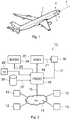
- FIG. 1illustrates, in a simplified manner, an aircraft comprising a cockpit.
- FIG. 2illustrates schematically one embodiment, according to the invention, of a display system for a cockpit of an aircraft.
- FIGS. 3 a , 3 b and 3 cillustrate the orientation of the head of a user of the display system, respectively in a top view, in a side view and in a rear view.
- FIG. 4illustrates one example of a usual display on an HMD display device.
- FIG. 5illustrates, in a top view, a cockpit of an aircraft equipped with a display system according to one embodiment of the invention.
- FIGS. 6 and 7illustrate a display, on an HMD display device, according to one embodiment of the invention.
- the aircraft 1 shown in FIG. 1comprises a cockpit 3 in a front part 4 of the said aircraft. It comprises a longitudinal axis 5 , corresponding to a roll axis of the aircraft. This longitudinal axis is substantially horizontal when the aircraft is parked on the ground.
- the aircraftalso comprises a yaw axis (not shown), substantially vertical when the aircraft is parked on the ground.
- horizontaldenotes a straight line or a plane that is substantially horizontal when the aircraft is parked on the ground, such that this straight line or this plane is perpendicular to the yaw axis of the aircraft.
- the term verticaldenotes a straight line or a plane that is substantially vertical when the aircraft is parked on the ground, such that this straight line or this plane is parallel to (or contains) the yaw axis of the aircraft.
- the display system 10 shown in FIG. 2comprises a display computer 18 comprising a processing unit (labelled PROC in the figure).
- This processing unitmay notably correspond to a processor or a microprocessor of the display computer.
- the display computer 18is a common display computer controlling several display devices of the aircraft or else a computer dedicated to the display system 10 .
- this computercorresponds to a computer of the IMA (for Integrated Modular Avionics) type also supporting functions other than the display.
- the display system 10furthermore comprises a display device 20 configured so as to be worn rigidly attached to the head of a user in the cockpit of the aircraft.
- This display devicecorresponds to an HMD (or HWD) display device such as previously mentioned.
- the display computer 18is connected to at least one avionics computer 12 of the aircraft.
- the display computeris connected to several avionics computers 12 via a link 15 of a communications network 14 (labelled “Net” in the figure) to which these avionics computers are also connected.
- the avionics computers 12are for example situated in an avionics rack 2 of the aircraft.
- the display system 10also comprises at least one masking device 24 (labelled “Mask” in the figure) associated with a side window 6 a , 6 b of the cockpit 3 . This masking device is connected to the display computer 18 via a link 25 .
- the masking device 24is able to be controlled, by means of the link 25 , between a first state called transparent in which it allows a user situated in the cockpit to see the environment outside of the aircraft through the side window of the cockpit, and at least a second state called opaque in which this masking device masks the view of the environment outside of the aircraft from the user through at least one predetermined masking surface of the side window.
- the masking device 24corresponds to an electrochromatic or electro-optic film applied onto the said predetermined masking surface of the side window. It is controllable between the first transparent state and the second opaque state by application of an electrical voltage between two terminals of the said electrochromatic or electro-optic film.
- the absence of application of an electrical voltagecorresponds to the transparent state of the masking device, on the one hand, and an electrical voltage with a non-zero value (for example 10 volts) corresponds to the opaque state, on the other.
- the voltageis directly applied to the terminals of the electrochromatic or electro-optic film by means of the link 25 .
- a local controlleris situated near to the side window. This local controller is configured for controlling the application of a suitable voltage to the terminals of the electrochromatic or electro-optic film according to the instructions received from the display computer 18 via the link 25 .
- the display system 10furthermore comprises a sensor 16 for orientation and for position of the head of the user.
- This sensor 16is connected to the display computer 18 via a link 17 .
- the sensor 16is installed rigidly attached to the display device 20 , as symbolized by the dashed arrow 21 . It then corresponds, for example, to an assembly of inertial sensors integrated into the display device 20 .
- the sensor 16is installed rigidly attached to the cockpit 3 of the aircraft. It then corresponds, for example, to a camera disposed in such a manner as to automatically monitor the head of the user of the display device 20 .
- the sensor 16may correspond to a group of sensors, for example an orientation sensor for the head of the user and a position sensor for the head of the user.
- the display systemalso comprises a device 29 (labelled “Ext” in the figure) for enabling one mode of operation referred to as extended display.
- This devicecorresponds, for example, to a button in the cockpit of the aircraft or to a man-machine interface in the cockpit, comprising a display screen together with a keyboard and/or a point-and-click device of the trackball or mouse type.
- This device for enabling the extended display modeis configured for transmitting information to the display computer 18 depending on the actions of the user on the said device for enabling the extended display mode.
- the display computer 18is configured for enabling or disabling the extended display mode depending on the said information.
- the display computer 18controls, on the one hand, the transparent state of the masking device 24 and controls, on the other hand, the display on the display device HMD 20 , in a usual manner, according to a first display mode in which the display comprises at least one piece of flight assistance information for the aircraft relating to a current situation of the aircraft.
- This flight assistance informationcomes from the at least one avionics computer 12 or is determined by the display computer 18 as a function of information received from the at least one avionics computer 12 .
- FIG. 4One example of the display of a set of flight assistance information on the display device 20 , according to this first display mode, is shown in FIG. 4 .
- the display on a display unit 8 of the display device 20comprises for example an aircraft reference symbol 38 , a symbol 40 for speed vector of the aircraft and an attitude scale 36 for the aircraft, displayed in a manner that conforms to the environment of the aircraft.
- the displayalso comprises an altitude scale 32 , a speed scale 30 and a roll scale 34 for the aircraft.
- the cockpit of the aircraftcomprises a windscreen 4 comprising two front windows 7 a and 7 b , a left-side window 6 a and a right-side window 6 b .
- the userfor example a pilot of the aircraft, is seated in the cockpit in such a manner that his head 50 is situated near to the left-side window 6 a .
- the masking device 24is associated with the left-side window 6 a .
- the userwishes to dispose of an additional display location on the left-side window 6 a , for example for the display of a device of the EFB type, it controls the enabling of the extended display mode by means of the device 29 .
- the display computer 18receives the command for enabling the extended display mode and it then implements the following steps in a repeated fashion:
- the display computercontrols the display on the display device 20 according to the first display mode, such as illustrated for example in FIG. 4 .
- the direction 52corresponding to the orientation of the head of the user then makes an intersection with the left-side window 6 a at a point of intersection Pi on the region of interest Zi shown in FIG. 6 .
- the determination of the point of intersection Piimplements normal geometrical calculations which are not further detailed here since they are available to those skilled in the art.
- the region of interest Ziis a predetermined region chosen so as to encompass a display area Zd.
- the region of interest Ziis defined taking into account a right lateral margin and a left lateral margin with respect to the display area Zd, together with a top vertical margin and a bottom vertical margin with respect to the display area Zd.
- the display area Zdcorresponds to an area of the side window 6 a provided for the display of the virtual display screen.
- the lateral and vertical margins between the display area Zd and the region of interest Ziare predefined in such a manner that the point of intersection Pi is situated within the region of interest Zi when the display area Zd is situated at least in part within the field of vision of the user visible through the display device 20 (which corresponds to a situation in which the virtual display screen is able to be displayed, at least in part, by the display device 20 , on the display area Zd).
- the region of interest Zicorresponds to the whole of the surface area of the side window 6 a .
- the direction 52 corresponding to the orientation of the head of the userhas an intersection, at a point Pi, with the region of interest Zi whenever the said direction 52 corresponding to the orientation of the head of the user makes an intersection with the side window 6 a.
- the display system 10comprises a memory comprising information on position of the side window 6 a in a reference frame of the cockpit.
- this memoryis a memory of the display computer 18 .
- this memorycorresponds to a memory or to a database 28 external to the display computer 18 and connected to the display computer 18 via a link 27 , such as shown in FIG. 2 .
- this memorycontains position information on the region of interest Zi and/or on the display area Zd.
- the said lateral and vertical marginsare predefined in the display computer 18 and the latter determines the region of interest Zi as a function of the display area Zd and of the said margins.
- the memorycontains information on position of the side window 6 a .
- the characteristics (in particular the dimensions) of the display area Zd and of the region of interest Ziare predetermined in the display computer 18 .
- the display computerdetermines the positions of the display area Zd and of the region of interest Zi. In one particular exemplary embodiment, the display computer determines these positions by considering the display area Zd as being centered on the side window 6 a.
- the display computer 18which has determined the direction 52 corresponding to the orientation of the head of the user, together with the position of the region of interest Zi, can thus determine whether the direction 52 corresponding to the orientation of the head of the user has an intersection with the region of interest Zi.
- the display computeris furthermore configured for determining a distance between a current position of the eyes of the user and the display area Zd of the side window.
- the display computer 18calculates this distance as a function, on the one hand, of the position of the head of the user in the cockpit and, on the other hand, of the position of the display area Zd.
- the display system 10furthermore comprises a distance sensor associated with the display device 20 . This distance sensor corresponds for example to a sensor using waves such as ultrasound waves or electromagnetic waves, in particular of the infrared type.
- the display computer 18carries out the acquisition of a measurement supplied by the said sensor and it determines the distance between the current position of the eyes of the user and the display area Zd as a function of the measurement supplied by the sensor.
- the display computeruses a predetermined value of distance as value of the distance between the current position of the eyes of the user and the display area Zd of the side window. This value of distance is for example predetermined as a function of a theoretical position of the head 50 of the user in the cockpit 3 of the aircraft.
- the display computer 18controls the display of the virtual display screen on the display device 20 with a collimation distance substantially corresponding to the distance determined between the current position of the eyes of the user and the side window display area. This allows the user to see the virtual display screen as if it were a real screen disposed on the side window 6 a.
- the display system 10is connected at the input to this device of the EFB type.
- the display computer 18comprises a video input connected to a video output of the device of the EFB type.
- the display computer 18controls the display, on the virtual display screen, in such a manner that this display corresponds to information coming from the video output of the device of the EFB type.
- the display computer 18is furthermore configured for acquiring, from an avionics computer of the aircraft, information on the current flight phase of the aircraft.
- the display computer 18controls the opaque state of the masking device when the extended display mode is enabled.
- the predetermined flight phasecorresponds for example to a cruising flight phase. In such a flight phase, a pilot has less need to see the environment outside of the aircraft through the side window 6 a than during a taxiing phase or of a landing phase.
- This particular embodimenthas the advantage of avoiding successive switching operations between the transparent state and the opaque state of the masking device 24 according to the orientation of the head of the user.
- a masking device 24 associated with the left-side window 6 a of the cockpitnotably when the user is a pilot of the aircraft whose head is situated near to the said left-side window 6 a .
- the inventionis similarly applicable to a masking device 24 associated with a right-side window 6 b of the cockpit, notably when the user is a copilot of the aircraft whose head is situated near to the said right-side window 6 b.
- the information on orientation of the head of the usercorresponds to at least one angle from amongst a set of angles, such as illustrated in FIGS. 3 a , 3 b and 3 c .
- the orientation of the head 50 of the useris represented by a straight line 52 .
- this straight line 52corresponds to a theoretical direction of the gaze of the user when he/she is looking towards the front without turning his/her eyes either to the right or to the left and without raising or lowering his/her eyes.
- Other definitions of the orientation of the head of the userare however possible without straying from the scope of the invention.
- the information on orientation of the head of the usercorresponds to at least one angle from amongst a yaw angle ⁇ , a pitch angle ⁇ and a roll angle ⁇ respectively illustrated in FIGS. 3 a , 3 b and 3 c .
- These anglesare defined in a reference frame linked to the aircraft.
- the yaw angle ⁇is an angle, defined in a projection onto a horizontal plane, between a straight line 5 ′ parallel to the longitudinal axis 5 of the aircraft and the straight line 52 representing the orientation of the head of the user.
- the pitch angle ⁇is an angle, defined in a projection onto a vertical plane parallel to the longitudinal axis 5 of the aircraft, between a straight line 5 ′′ parallel to the longitudinal axis 5 of the aircraft and the straight line 52 representing the orientation of the head of the user.
- the roll angle ⁇is an angle defined in a projection onto a vertical plane perpendicular to the longitudinal axis 5 of the aircraft, between a vertical straight line 56 and a yaw axis 54 of the head of the user.
- the orientation information on the head of the user acquired by the display computer 18corresponds to at least one of the angles ⁇ , ⁇ and ⁇ .
- the position information on the head of the usercorresponds to Cartesian coordinates, in an orthonormal reference frame, of a point situated at the center of a segment connecting both eyes of the user.
- a first axis of the orthonormal reference frameis parallel to the longitudinal axis 5
- a second axis of the orthonormal reference frameis vertical
- a third axis of the orthonormal reference frameis horizontal and perpendicular to the first two axes.
Landscapes
- Physics & Mathematics (AREA)
- Engineering & Computer Science (AREA)
- Aviation & Aerospace Engineering (AREA)
- General Physics & Mathematics (AREA)
- Optics & Photonics (AREA)
- Radar, Positioning & Navigation (AREA)
- Remote Sensing (AREA)
- Controls And Circuits For Display Device (AREA)
Abstract
Description
- a display device configured so as to be worn rigidly attached to the head of a user in the cockpit of the aircraft; and
- a display computer configured for controlling the display on the display device according to a first display mode in which the display comprises at least one piece of flight assistance information for the aircraft relating to a current situation of the aircraft.
- a masking device associated with a side window of the cockpit, the masking device being controllable between, on the one hand, a first state called transparent state in which it allows the user to see the environment outside of the aircraft through the side window and, on the other hand, a second state called opaque in which the masking device masks the view of the environment outside of the aircraft from the user through at least one predetermined masking surface of the side window; and
- a sensor for position and for orientation of the head of the user in the cockpit,
- acquiring from the sensor, position information and orientation information on the head of the user in the cockpit;
- determining a direction corresponding to the orientation of the head of the user as a function of the information on position and on orientation of the head of the user in the cockpit;
- determining whether the direction corresponding to the orientation of the head of the user has an intersection with a region of interest including an area referred to as display area included in the predetermined masking surface of the side window;
- when the direction corresponding to the orientation of the head of the user does not have an intersection with the region of interest, controlling the display on the display device according to the first display mode; and
- when the direction corresponding to the orientation of the head of the user has an intersection with the region of interest, controlling the opaque state of the masking device and controlling the display on the display device according to a second display mode in which the said display comprises a virtual display screen on the display area.
- the display system furthermore comprises a device for enabling the extended display mode, and the display computer is configured for enabling or disabling the extended display mode according to the actions of the user on the device for enabling the extended display mode;
- the display computer is configured for:
- acquiring, from an avionics computer of the aircraft, information on the current flight phase of the aircraft; and
- when the information on the current flight phase of the aircraft corresponds to a predetermined flight phase, controlling the opaque state of the masking device when the extended display mode is enabled;
- in the second display mode, the display computer is furthermore configured for:
- determining a distance between a current position of the eyes of the user and the side window display area; and
- controlling the display of the said virtual display screen on the display device with a collimation distance substantially corresponding to the distance determined between the current position of the eyes of the user and the side window display area.
- the display system is connected at its input to a device of the EFB type and, in the second display mode, the display on the virtual display screen corresponds to information coming from the device of the EFB type.
- a display device configured so as to be worn rigidly attached to the head of a user in the cockpit of the aircraft; and
- a display computer configured for controlling the display on the display device according to a first display mode in which the display comprises at least one piece of flight assistance information for the aircraft relating to a current situation of the aircraft.
- a masking device associated with a side window of the cockpit, the masking device being controllable between, on the one hand, a first state called transparent in which it allows the user to see the environment outside of the aircraft through the side window and, on the other hand, a second state called opaque in which the masking device masks the view of the environment outside of the aircraft from the user through at least one predetermined masking surface of the side window; and
- a sensor for position and for orientation of the head of the user in the cockpit,
- acquire from the sensor, position information and orientation information on the head of the user in the cockpit;
- determine a direction corresponding to the orientation of the head of the user as a function of the information on position and on orientation of the head of the user in the cockpit;
- determine whether the direction corresponding to the orientation of the head of the user has an intersection with a region of interest including an area referred to as display area included within the predetermined masking surface of the side window;
- when the direction corresponding to the orientation of the head of the user does not have an intersection with the region of interest, control the display on the display device according to the first display mode; and
- when the direction corresponding to the orientation of the head of the user has an intersection with the region of interest, control the opaque state of the masking device and control the display on the display device according to a second display mode in which the said display comprises a virtual display screen on the display area.
- acquire, from the
sensor 16, position information and orientation information on the head of the user in the cockpit; - determine a
direction 52, as illustrated inFIG. 5 , corresponding to the orientation of the head of the user, as a function of the information on position and on orientation of the head of the user in the cockpit; - determine whether the
direction 52 corresponding to the orientation of the head of the user has an intersection with a region of interest Zi including an area referred to as display area Zd included in the predetermined masking surface of theside window 6aby the maskingdevice 24; - when the
direction 52 corresponding to the orientation of the head of the user does not have an intersection with the region of interest, control the display on the display device according to the first display mode, such as illustrated by way of example inFIG. 4 . Advantageously, although not necessarily, the display computer then also controls the transparent mode of themasking device 24; and - when the
direction 52 corresponding to the orientation of the head of the user has an intersection, at a point Pi, with the region of interest, control the opaque state of themasking device 24 and control the display on thedisplay device 20 according to a second display mode in which the said display comprises a virtual display screen on the display area Zd.
- acquire, from the
Claims (7)
Applications Claiming Priority (2)
| Application Number | Priority Date | Filing Date | Title |
|---|---|---|---|
| FR1756020AFR3068481B1 (en) | 2017-06-29 | 2017-06-29 | DISPLAY SYSTEM AND METHOD FOR AN AIRCRAFT |
| FR1756020 | 2017-06-29 |
Publications (2)
| Publication Number | Publication Date |
|---|---|
| US20190004318A1 US20190004318A1 (en) | 2019-01-03 |
| US10627630B2true US10627630B2 (en) | 2020-04-21 |
Family
ID=60182669
Family Applications (1)
| Application Number | Title | Priority Date | Filing Date |
|---|---|---|---|
| US16/016,918ActiveUS10627630B2 (en) | 2017-06-29 | 2018-06-25 | Display system and method for an aircraft |
Country Status (2)
| Country | Link |
|---|---|
| US (1) | US10627630B2 (en) |
| FR (1) | FR3068481B1 (en) |
Families Citing this family (8)
| Publication number | Priority date | Publication date | Assignee | Title |
|---|---|---|---|---|
| FR3098932B1 (en)* | 2019-07-15 | 2023-12-22 | Airbus Helicopters | Method and system for assisting the piloting of an aircraft by adaptive display on a screen |
| US11315434B2 (en) | 2019-10-31 | 2022-04-26 | Rockwell Collins, Inc. | System and method to change SVS mode |
| FR3102755B1 (en) | 2019-10-31 | 2021-10-15 | Airbus Helicopters | Method of assisting in piloting an aircraft |
| US11097851B1 (en) | 2019-11-19 | 2021-08-24 | Rockwell Collins, Inc. | System and method to momentarily switch SVS mode |
| US12017792B2 (en) | 2020-04-14 | 2024-06-25 | Rockwell Collins, Inc. | System and method to change map range of airport moving map |
| US11610497B2 (en) | 2020-12-15 | 2023-03-21 | Rockwell Collins, Inc. | System and method to display SVS taxi mode exocentric view of aircraft |
| US12025456B2 (en) | 2021-03-29 | 2024-07-02 | Rockwell Collins, Inc. | System and method to display airport moving map and taxi routing guidance content |
| US12249244B2 (en) | 2021-03-29 | 2025-03-11 | Rockwell Collins, Inc. | System and method to display airport moving map and taxi routing guidance content for commonly used taxi route |
Citations (64)
| Publication number | Priority date | Publication date | Assignee | Title |
|---|---|---|---|---|
| US20020048678A1 (en)* | 2000-10-17 | 2002-04-25 | Hunia Robert M. | Polymeric electrochromic devices |
| US6405975B1 (en)* | 1995-12-19 | 2002-06-18 | The Boeing Company | Airplane ground maneuvering camera system |
| US6847336B1 (en) | 1996-10-02 | 2005-01-25 | Jerome H. Lemelson | Selectively controllable heads-up display system |
| US20050237226A1 (en)* | 2003-03-31 | 2005-10-27 | Judge John H | Integrated hover display with augmented approach to hover symbology cueing for degraded visual environmental conditions |
| US20060037038A1 (en)* | 2004-06-21 | 2006-02-16 | Trading Technologies International, Inc. | System and method for display management based on user attention inputs |
| US20060056026A1 (en)* | 2002-04-16 | 2006-03-16 | Aleksandra Kolosowsky | Method for eliminating strong ambient light in aircraft cockpits |
| US20080218434A1 (en)* | 2007-03-05 | 2008-09-11 | The Boeing Company | Electrically Dimmable Combiner Optics for Head-Up Display |
| US20090034087A1 (en)* | 2007-05-30 | 2009-02-05 | Opus Microsystems Corporation | Head-up display system |
| US20090058126A1 (en)* | 2007-09-05 | 2009-03-05 | Craig Broude | Glare reduction |
| US20090201177A1 (en)* | 2006-07-11 | 2009-08-13 | Thales | Secure head-up display |
| US7629877B2 (en)* | 2006-12-19 | 2009-12-08 | Matvey Lvovskiy | Multifunctional collimator indicator |
| US20090317773A1 (en)* | 2008-06-24 | 2009-12-24 | United States Of America As Represented By The Administrator Of The N.A.S.A. | Variably Transmittive, Electronically-Controlled Eyewear |
| US20100094501A1 (en)* | 2008-10-09 | 2010-04-15 | Angela Karen Kwok | System and Methods for an Automated Sun Glare Block Area and Sunshield in a Vehicular Windshield |
| US20110157667A1 (en)* | 2008-06-26 | 2011-06-30 | Lilian Lacoste | Holographic Image Display Systems |
| US20120140125A1 (en)* | 2010-12-03 | 2012-06-07 | Honeywell International Inc. | Aircraft cockpit visor display |
| US20120179369A1 (en) | 2005-02-17 | 2012-07-12 | Lumus Ltd. | Personal navigation system |
| US20130181887A1 (en)* | 2012-01-12 | 2013-07-18 | Htc Corporation | Head up display, vehicle and controlling method of head up display |
| US20140111864A1 (en)* | 2011-06-22 | 2014-04-24 | Elbit Systems Ltd. | Helmet mounted display system adjustable for bright ambient light conditions |
| US20140253579A1 (en)* | 2013-03-05 | 2014-09-11 | Funai Electric Co., Ltd. | Headup Display, Display Method for Headup Display and Program for Headup Display |
| EP2793070A1 (en) | 2013-04-19 | 2014-10-22 | Thales | Hybrid viewing system for displaying information superimposed on the outside |
| US20140333510A1 (en)* | 2013-05-08 | 2014-11-13 | Gulfstream Aerospace Corporation | Omnidirectional hud |
| US20150092083A1 (en)* | 2013-09-30 | 2015-04-02 | Nghia Trong Lam | Active Shielding Against Intense Illumination (ASAII) System for Direct Viewing |
| US20150128037A1 (en)* | 2013-11-05 | 2015-05-07 | Lg Electronics Inc. | Mobile terminal and method of controlling the same terminal |
| US20150151838A1 (en)* | 2013-12-03 | 2015-06-04 | Federal Express Corporation | System and method for enhancing vision inside an aircraft cockpit |
| US20150191075A1 (en)* | 2014-01-09 | 2015-07-09 | The Boeing Company | Augmented situation awareness |
| US20150232030A1 (en)* | 2014-02-19 | 2015-08-20 | Magna Electronics Inc. | Vehicle vision system with display |
| US9168869B1 (en)* | 2014-12-29 | 2015-10-27 | Sami Yaseen Kamal | Vehicle with a multi-function auxiliary control system and heads-up display |
| US20160085301A1 (en)* | 2014-09-22 | 2016-03-24 | The Eye Tribe Aps | Display visibility based on eye convergence |
| US20160109973A1 (en)* | 2014-10-20 | 2016-04-21 | Samsung Electronics Co., Ltd. | Display apparatus and display method thereof |
| US20160150201A1 (en)* | 2014-11-20 | 2016-05-26 | Lucio Kilcher | Virtual image generator |
| US20160170487A1 (en)* | 2014-12-10 | 2016-06-16 | Kenichiroh Saisho | Information provision device and information provision method |
| US20160187650A1 (en)* | 2013-08-13 | 2016-06-30 | Bae Systems Plc | Improvements in and relating to visors |
| US20160214467A1 (en)* | 2013-09-26 | 2016-07-28 | Valeo Vision | Driving assistance device and method |
| US20160311323A1 (en)* | 2015-04-27 | 2016-10-27 | Lg Electronics Inc. | Display Apparatus And Method For Controlling The Same |
| US20160377862A1 (en)* | 2015-06-29 | 2016-12-29 | Rockwell Collins, Inc. | System for and method of integrating head up displays and head down displays |
| US20170032571A1 (en) | 2015-07-30 | 2017-02-02 | Honeywell International Inc. | Methods and systems for displaying information on a heads-up display |
| US20170113702A1 (en)* | 2015-10-26 | 2017-04-27 | Active Knowledge Ltd. | Warning a vehicle occupant before an intense movement |
| US20170113641A1 (en)* | 2015-10-26 | 2017-04-27 | Active Knowledge Ltd. | Moveable internal shock-absorbing energy dissipation padding in an autonomous vehicle |
| US20170146797A1 (en)* | 2015-11-24 | 2017-05-25 | Honeywell International Inc. | Systems and methods for displaying fov boundaries on huds |
| US20170187963A1 (en)* | 2015-12-24 | 2017-06-29 | Lg Electronics Inc. | Display device for vehicle and control method thereof |
| US20170212398A1 (en)* | 2015-07-20 | 2017-07-27 | Boe Technology Group Co., Ltd. | Display panel and display device |
| US20170214904A1 (en)* | 2016-01-27 | 2017-07-27 | Honeywell International Inc. | Cockpit display systems and methods for generating cockpit displays including enhanced flight visibility indicators |
| US20170269370A1 (en)* | 2016-03-18 | 2017-09-21 | Fuji Jukogyo Kabushiki Kaisha | Display control device for vehicle |
| US20170270899A1 (en)* | 2016-03-18 | 2017-09-21 | Fuji Jukogyo Kabushiki Kaisha | Display control device for vehicle |
| US20170280024A1 (en)* | 2016-03-23 | 2017-09-28 | GM Global Technology Operations LLC | Dynamically colour adjusted visual overlays for augmented reality systems |
| US20170323615A1 (en)* | 2016-05-05 | 2017-11-09 | Ostendo Technologies, Inc. | Methods and Apparatus for Active Transparency Modulation |
| US20170343799A1 (en)* | 2016-05-30 | 2017-11-30 | Mazda Motor Corporation | Display apparatus for vehicle |
| US20180011314A1 (en)* | 2016-07-06 | 2018-01-11 | Continental Automotive Systems, Inc. | Side head up display |
| US20180015810A1 (en)* | 2016-07-12 | 2018-01-18 | Toyota Motor Engineering & Manufacturing North America, Inc. | Vehicle display screen safety and privacy system |
| US20180024359A1 (en)* | 2015-03-19 | 2018-01-25 | Fujifilm Corporation | Projection type display device and projection display method |
| US20180088323A1 (en)* | 2016-09-23 | 2018-03-29 | Sheng Bao | Selectably opaque displays |
| US20180089893A1 (en)* | 2016-09-23 | 2018-03-29 | Intel Corporation | Virtual guard rails |
| US20180101988A1 (en)* | 2016-10-11 | 2018-04-12 | Microsoft Technology Licensing, Llc | Virtual Reality Headset |
| US20180106098A1 (en)* | 2016-10-18 | 2018-04-19 | Dura Operating, Llc | Window assembly with selectable tint |
| US20180111451A1 (en)* | 2016-10-26 | 2018-04-26 | International Business Machines Corporation | Automated windshield glare elimination assistant |
| US20180154860A1 (en)* | 2015-10-26 | 2018-06-07 | Active Knowledge Ltd. | Autonomous vehicle having an external shock-absorbing energy dissipation padding |
| US20180164115A1 (en)* | 2016-12-13 | 2018-06-14 | Inventec (Pudong) Technology Corporation | Vehicle Navigation Projection System And Method Thereof |
| US20180164114A1 (en)* | 2016-12-14 | 2018-06-14 | Inventec (Pudong) Technology Corporation | Vehicle Navigation Display System And Method Thereof |
| US20180204365A1 (en)* | 2017-01-13 | 2018-07-19 | Samsung Electronics Co., Ltd. | Electronic apparatus and method for controlling the same |
| US20180222490A1 (en)* | 2017-02-09 | 2018-08-09 | Toyota Motor Engineering & Manufacturing North America, Inc. | Systems and methods for adaptively communicating notices in a vehicle |
| US20180259804A1 (en)* | 2015-09-15 | 2018-09-13 | Samsung Electronics Co., Ltd. | Smart window system and control method therefor |
| US20180326999A1 (en)* | 2015-10-26 | 2018-11-15 | Active Knowledge Ltd. | Provide specific warnings to vehicle occupants before intense movements |
| US20180366090A1 (en)* | 2017-05-01 | 2018-12-20 | Elbit Systems Ltd | Head mounted display device, system and method |
| US20190137841A1 (en)* | 2016-04-08 | 2019-05-09 | Lg Electronics Inc. | Electrochromic device and electrochormic system |
- 2017
- 2017-06-29FRFR1756020Apatent/FR3068481B1/enactiveActive
- 2018
- 2018-06-25USUS16/016,918patent/US10627630B2/enactiveActive
Patent Citations (65)
| Publication number | Priority date | Publication date | Assignee | Title |
|---|---|---|---|---|
| US6405975B1 (en)* | 1995-12-19 | 2002-06-18 | The Boeing Company | Airplane ground maneuvering camera system |
| US6847336B1 (en) | 1996-10-02 | 2005-01-25 | Jerome H. Lemelson | Selectively controllable heads-up display system |
| US20020048678A1 (en)* | 2000-10-17 | 2002-04-25 | Hunia Robert M. | Polymeric electrochromic devices |
| US20060056026A1 (en)* | 2002-04-16 | 2006-03-16 | Aleksandra Kolosowsky | Method for eliminating strong ambient light in aircraft cockpits |
| US20050237226A1 (en)* | 2003-03-31 | 2005-10-27 | Judge John H | Integrated hover display with augmented approach to hover symbology cueing for degraded visual environmental conditions |
| US20060037038A1 (en)* | 2004-06-21 | 2006-02-16 | Trading Technologies International, Inc. | System and method for display management based on user attention inputs |
| US20120179369A1 (en) | 2005-02-17 | 2012-07-12 | Lumus Ltd. | Personal navigation system |
| US20090201177A1 (en)* | 2006-07-11 | 2009-08-13 | Thales | Secure head-up display |
| US7629877B2 (en)* | 2006-12-19 | 2009-12-08 | Matvey Lvovskiy | Multifunctional collimator indicator |
| US20080218434A1 (en)* | 2007-03-05 | 2008-09-11 | The Boeing Company | Electrically Dimmable Combiner Optics for Head-Up Display |
| US20090034087A1 (en)* | 2007-05-30 | 2009-02-05 | Opus Microsystems Corporation | Head-up display system |
| US20090058126A1 (en)* | 2007-09-05 | 2009-03-05 | Craig Broude | Glare reduction |
| US20090317773A1 (en)* | 2008-06-24 | 2009-12-24 | United States Of America As Represented By The Administrator Of The N.A.S.A. | Variably Transmittive, Electronically-Controlled Eyewear |
| US20110157667A1 (en)* | 2008-06-26 | 2011-06-30 | Lilian Lacoste | Holographic Image Display Systems |
| US20100094501A1 (en)* | 2008-10-09 | 2010-04-15 | Angela Karen Kwok | System and Methods for an Automated Sun Glare Block Area and Sunshield in a Vehicular Windshield |
| US20120140125A1 (en)* | 2010-12-03 | 2012-06-07 | Honeywell International Inc. | Aircraft cockpit visor display |
| US20140111864A1 (en)* | 2011-06-22 | 2014-04-24 | Elbit Systems Ltd. | Helmet mounted display system adjustable for bright ambient light conditions |
| US20130181887A1 (en)* | 2012-01-12 | 2013-07-18 | Htc Corporation | Head up display, vehicle and controlling method of head up display |
| US20140253579A1 (en)* | 2013-03-05 | 2014-09-11 | Funai Electric Co., Ltd. | Headup Display, Display Method for Headup Display and Program for Headup Display |
| EP2793070A1 (en) | 2013-04-19 | 2014-10-22 | Thales | Hybrid viewing system for displaying information superimposed on the outside |
| US20140313189A1 (en)* | 2013-04-19 | 2014-10-23 | Thales | Hybrid display system displaying information by superimposition on the exterior |
| US20140333510A1 (en)* | 2013-05-08 | 2014-11-13 | Gulfstream Aerospace Corporation | Omnidirectional hud |
| US20160187650A1 (en)* | 2013-08-13 | 2016-06-30 | Bae Systems Plc | Improvements in and relating to visors |
| US20160214467A1 (en)* | 2013-09-26 | 2016-07-28 | Valeo Vision | Driving assistance device and method |
| US20150092083A1 (en)* | 2013-09-30 | 2015-04-02 | Nghia Trong Lam | Active Shielding Against Intense Illumination (ASAII) System for Direct Viewing |
| US20150128037A1 (en)* | 2013-11-05 | 2015-05-07 | Lg Electronics Inc. | Mobile terminal and method of controlling the same terminal |
| US20150151838A1 (en)* | 2013-12-03 | 2015-06-04 | Federal Express Corporation | System and method for enhancing vision inside an aircraft cockpit |
| US20150191075A1 (en)* | 2014-01-09 | 2015-07-09 | The Boeing Company | Augmented situation awareness |
| US20150232030A1 (en)* | 2014-02-19 | 2015-08-20 | Magna Electronics Inc. | Vehicle vision system with display |
| US20160085301A1 (en)* | 2014-09-22 | 2016-03-24 | The Eye Tribe Aps | Display visibility based on eye convergence |
| US20160109973A1 (en)* | 2014-10-20 | 2016-04-21 | Samsung Electronics Co., Ltd. | Display apparatus and display method thereof |
| US20160150201A1 (en)* | 2014-11-20 | 2016-05-26 | Lucio Kilcher | Virtual image generator |
| US20160170487A1 (en)* | 2014-12-10 | 2016-06-16 | Kenichiroh Saisho | Information provision device and information provision method |
| US9168869B1 (en)* | 2014-12-29 | 2015-10-27 | Sami Yaseen Kamal | Vehicle with a multi-function auxiliary control system and heads-up display |
| US20180024359A1 (en)* | 2015-03-19 | 2018-01-25 | Fujifilm Corporation | Projection type display device and projection display method |
| US20160311323A1 (en)* | 2015-04-27 | 2016-10-27 | Lg Electronics Inc. | Display Apparatus And Method For Controlling The Same |
| US20160377862A1 (en)* | 2015-06-29 | 2016-12-29 | Rockwell Collins, Inc. | System for and method of integrating head up displays and head down displays |
| US20170212398A1 (en)* | 2015-07-20 | 2017-07-27 | Boe Technology Group Co., Ltd. | Display panel and display device |
| US20170032571A1 (en) | 2015-07-30 | 2017-02-02 | Honeywell International Inc. | Methods and systems for displaying information on a heads-up display |
| US20180259804A1 (en)* | 2015-09-15 | 2018-09-13 | Samsung Electronics Co., Ltd. | Smart window system and control method therefor |
| US20170113702A1 (en)* | 2015-10-26 | 2017-04-27 | Active Knowledge Ltd. | Warning a vehicle occupant before an intense movement |
| US20170113641A1 (en)* | 2015-10-26 | 2017-04-27 | Active Knowledge Ltd. | Moveable internal shock-absorbing energy dissipation padding in an autonomous vehicle |
| US20180326999A1 (en)* | 2015-10-26 | 2018-11-15 | Active Knowledge Ltd. | Provide specific warnings to vehicle occupants before intense movements |
| US20180154860A1 (en)* | 2015-10-26 | 2018-06-07 | Active Knowledge Ltd. | Autonomous vehicle having an external shock-absorbing energy dissipation padding |
| US20170146797A1 (en)* | 2015-11-24 | 2017-05-25 | Honeywell International Inc. | Systems and methods for displaying fov boundaries on huds |
| US20170187963A1 (en)* | 2015-12-24 | 2017-06-29 | Lg Electronics Inc. | Display device for vehicle and control method thereof |
| US20170214904A1 (en)* | 2016-01-27 | 2017-07-27 | Honeywell International Inc. | Cockpit display systems and methods for generating cockpit displays including enhanced flight visibility indicators |
| US20170270899A1 (en)* | 2016-03-18 | 2017-09-21 | Fuji Jukogyo Kabushiki Kaisha | Display control device for vehicle |
| US20170269370A1 (en)* | 2016-03-18 | 2017-09-21 | Fuji Jukogyo Kabushiki Kaisha | Display control device for vehicle |
| US20170280024A1 (en)* | 2016-03-23 | 2017-09-28 | GM Global Technology Operations LLC | Dynamically colour adjusted visual overlays for augmented reality systems |
| US20190137841A1 (en)* | 2016-04-08 | 2019-05-09 | Lg Electronics Inc. | Electrochromic device and electrochormic system |
| US20170323615A1 (en)* | 2016-05-05 | 2017-11-09 | Ostendo Technologies, Inc. | Methods and Apparatus for Active Transparency Modulation |
| US20170343799A1 (en)* | 2016-05-30 | 2017-11-30 | Mazda Motor Corporation | Display apparatus for vehicle |
| US20180011314A1 (en)* | 2016-07-06 | 2018-01-11 | Continental Automotive Systems, Inc. | Side head up display |
| US20180015810A1 (en)* | 2016-07-12 | 2018-01-18 | Toyota Motor Engineering & Manufacturing North America, Inc. | Vehicle display screen safety and privacy system |
| US20180089893A1 (en)* | 2016-09-23 | 2018-03-29 | Intel Corporation | Virtual guard rails |
| US20180088323A1 (en)* | 2016-09-23 | 2018-03-29 | Sheng Bao | Selectably opaque displays |
| US20180101988A1 (en)* | 2016-10-11 | 2018-04-12 | Microsoft Technology Licensing, Llc | Virtual Reality Headset |
| US20180106098A1 (en)* | 2016-10-18 | 2018-04-19 | Dura Operating, Llc | Window assembly with selectable tint |
| US20180111451A1 (en)* | 2016-10-26 | 2018-04-26 | International Business Machines Corporation | Automated windshield glare elimination assistant |
| US20180164115A1 (en)* | 2016-12-13 | 2018-06-14 | Inventec (Pudong) Technology Corporation | Vehicle Navigation Projection System And Method Thereof |
| US20180164114A1 (en)* | 2016-12-14 | 2018-06-14 | Inventec (Pudong) Technology Corporation | Vehicle Navigation Display System And Method Thereof |
| US20180204365A1 (en)* | 2017-01-13 | 2018-07-19 | Samsung Electronics Co., Ltd. | Electronic apparatus and method for controlling the same |
| US20180222490A1 (en)* | 2017-02-09 | 2018-08-09 | Toyota Motor Engineering & Manufacturing North America, Inc. | Systems and methods for adaptively communicating notices in a vehicle |
| US20180366090A1 (en)* | 2017-05-01 | 2018-12-20 | Elbit Systems Ltd | Head mounted display device, system and method |
Non-Patent Citations (1)
| Title |
|---|
| French Search Report, dated Feb. 16, 2018, priority document. |
Also Published As
| Publication number | Publication date |
|---|---|
| US20190004318A1 (en) | 2019-01-03 |
| FR3068481A1 (en) | 2019-01-04 |
| FR3068481B1 (en) | 2019-07-26 |
Similar Documents
| Publication | Publication Date | Title |
|---|---|---|
| US10627630B2 (en) | Display system and method for an aircraft | |
| EP3414616B1 (en) | Head mounted display device, system and method | |
| US12162622B2 (en) | Augmented reality system for pilot and passengers | |
| EP2133729B1 (en) | Method and system for operating a near-to-eye display | |
| JP6837805B2 (en) | Design and method of correction of vestibulo-omotor reflex in display system | |
| EP2124088B1 (en) | Methods for operating avionic systems based on user gestures | |
| US10235777B2 (en) | Display System and method for an aircraft | |
| WO2012103312A1 (en) | 3d avionics viewpoint control system | |
| CN109436348A (en) | For adjusting the aircraft system and method for shown sensor image visual field | |
| KR20090127837A (en) | Method and system for operating a display device | |
| US11048079B2 (en) | Method and system for display and interaction embedded in a cockpit | |
| US10326985B2 (en) | Display system and method for an aircraft | |
| US20180261148A1 (en) | Display system and method for an aircraft | |
| US20170146800A1 (en) | System and method for facilitating cross-checking between flight crew members using wearable displays | |
| US20200192468A1 (en) | Display system and method for an aircraft | |
| EP3246905B1 (en) | Displaying data by a display system | |
| US11403058B2 (en) | Augmented reality vision system for vehicular crew resource management | |
| US9746343B1 (en) | Steering command generating system, device, and method for a forward-looking image capture device |
Legal Events
| Date | Code | Title | Description |
|---|---|---|---|
| AS | Assignment | Owner name:AIRBUS OPERATIONS SAS, FRANCE Free format text:ASSIGNMENT OF ASSIGNORS INTEREST;ASSIGNORS:MANJON SANCHEZ, JAVIER;DESCHEEMAEKER, CEDRIC;REEL/FRAME:046189/0907 Effective date:20180612 | |
| FEPP | Fee payment procedure | Free format text:ENTITY STATUS SET TO UNDISCOUNTED (ORIGINAL EVENT CODE: BIG.); ENTITY STATUS OF PATENT OWNER: LARGE ENTITY | |
| STPP | Information on status: patent application and granting procedure in general | Free format text:DOCKETED NEW CASE - READY FOR EXAMINATION | |
| STPP | Information on status: patent application and granting procedure in general | Free format text:NON FINAL ACTION MAILED | |
| STPP | Information on status: patent application and granting procedure in general | Free format text:RESPONSE TO NON-FINAL OFFICE ACTION ENTERED AND FORWARDED TO EXAMINER | |
| STPP | Information on status: patent application and granting procedure in general | Free format text:NOTICE OF ALLOWANCE MAILED -- APPLICATION RECEIVED IN OFFICE OF PUBLICATIONS | |
| STPP | Information on status: patent application and granting procedure in general | Free format text:AWAITING TC RESP., ISSUE FEE NOT PAID | |
| STCF | Information on status: patent grant | Free format text:PATENTED CASE | |
| MAFP | Maintenance fee payment | Free format text:PAYMENT OF MAINTENANCE FEE, 4TH YEAR, LARGE ENTITY (ORIGINAL EVENT CODE: M1551); ENTITY STATUS OF PATENT OWNER: LARGE ENTITY Year of fee payment:4 |