US10627592B2 - Fiber optic assembly with cable spool - Google Patents
Fiber optic assembly with cable spoolDownload PDFInfo
- Publication number
- US10627592B2 US10627592B2US16/185,315US201816185315AUS10627592B2US 10627592 B2US10627592 B2US 10627592B2US 201816185315 AUS201816185315 AUS 201816185315AUS 10627592 B2US10627592 B2US 10627592B2
- Authority
- US
- United States
- Prior art keywords
- fiber optic
- cable
- spool
- base
- enclosure
- Prior art date
- Legal status (The legal status is an assumption and is not a legal conclusion. Google has not performed a legal analysis and makes no representation as to the accuracy of the status listed.)
- Active
Links
Images


Classifications
- G—PHYSICS
- G02—OPTICS
- G02B—OPTICAL ELEMENTS, SYSTEMS OR APPARATUS
- G02B6/00—Light guides; Structural details of arrangements comprising light guides and other optical elements, e.g. couplings
- G02B6/44—Mechanical structures for providing tensile strength and external protection for fibres, e.g. optical transmission cables
- G02B6/4439—Auxiliary devices
- G02B6/4457—Bobbins; Reels
- G—PHYSICS
- G02—OPTICS
- G02B—OPTICAL ELEMENTS, SYSTEMS OR APPARATUS
- G02B6/00—Light guides; Structural details of arrangements comprising light guides and other optical elements, e.g. couplings
- G02B6/24—Coupling light guides
- G02B6/36—Mechanical coupling means
- G02B6/38—Mechanical coupling means having fibre to fibre mating means
- G02B6/3807—Dismountable connectors, i.e. comprising plugs
- G02B6/3897—Connectors fixed to housings, casing, frames or circuit boards
- G—PHYSICS
- G02—OPTICS
- G02B—OPTICAL ELEMENTS, SYSTEMS OR APPARATUS
- G02B6/00—Light guides; Structural details of arrangements comprising light guides and other optical elements, e.g. couplings
- G02B6/44—Mechanical structures for providing tensile strength and external protection for fibres, e.g. optical transmission cables
- G02B6/4439—Auxiliary devices
- G02B6/444—Systems or boxes with surplus lengths
- G02B6/4452—Distribution frames
- G02B6/44524—Distribution frames with frame parts or auxiliary devices mounted on the frame and collectively not covering a whole width of the frame or rack
- G—PHYSICS
- G02—OPTICS
- G02B—OPTICAL ELEMENTS, SYSTEMS OR APPARATUS
- G02B6/00—Light guides; Structural details of arrangements comprising light guides and other optical elements, e.g. couplings
- G02B6/44—Mechanical structures for providing tensile strength and external protection for fibres, e.g. optical transmission cables
- G02B6/4439—Auxiliary devices
- G02B6/444—Systems or boxes with surplus lengths
- G02B6/44528—Patch-cords; Connector arrangements in the system or in the box
- G02B6/4466—
- G—PHYSICS
- G02—OPTICS
- G02B—OPTICAL ELEMENTS, SYSTEMS OR APPARATUS
- G02B6/00—Light guides; Structural details of arrangements comprising light guides and other optical elements, e.g. couplings
- G02B6/44—Mechanical structures for providing tensile strength and external protection for fibres, e.g. optical transmission cables
- G02B6/4439—Auxiliary devices
- G02B6/4471—Terminating devices ; Cable clamps
- G02B6/44765—Terminating devices ; Cable clamps with means for strain-relieving to exterior cable layers
- G—PHYSICS
- G02—OPTICS
- G02B—OPTICAL ELEMENTS, SYSTEMS OR APPARATUS
- G02B6/00—Light guides; Structural details of arrangements comprising light guides and other optical elements, e.g. couplings
- G02B6/44—Mechanical structures for providing tensile strength and external protection for fibres, e.g. optical transmission cables
- G02B6/4439—Auxiliary devices
- G02B6/4471—Terminating devices ; Cable clamps
- G02B6/4477—Terminating devices ; Cable clamps with means for strain-relieving to interior strengths element
- G—PHYSICS
- G02—OPTICS
- G02B—OPTICAL ELEMENTS, SYSTEMS OR APPARATUS
- G02B6/00—Light guides; Structural details of arrangements comprising light guides and other optical elements, e.g. couplings
- G02B6/44—Mechanical structures for providing tensile strength and external protection for fibres, e.g. optical transmission cables
- G02B6/4439—Auxiliary devices
- G02B6/4471—Terminating devices ; Cable clamps
- G02B6/4478—Bending relief means
- G—PHYSICS
- G02—OPTICS
- G02B—OPTICAL ELEMENTS, SYSTEMS OR APPARATUS
- G02B6/00—Light guides; Structural details of arrangements comprising light guides and other optical elements, e.g. couplings
- G02B6/46—Processes or apparatus adapted for installing or repairing optical fibres or optical cables
- G02B6/47—Installation in buildings
- G02B6/475—Mechanical aspects of installing cables in ducts or the like for buildings
- Y—GENERAL TAGGING OF NEW TECHNOLOGICAL DEVELOPMENTS; GENERAL TAGGING OF CROSS-SECTIONAL TECHNOLOGIES SPANNING OVER SEVERAL SECTIONS OF THE IPC; TECHNICAL SUBJECTS COVERED BY FORMER USPC CROSS-REFERENCE ART COLLECTIONS [XRACs] AND DIGESTS
- Y10—TECHNICAL SUBJECTS COVERED BY FORMER USPC
- Y10T—TECHNICAL SUBJECTS COVERED BY FORMER US CLASSIFICATION
- Y10T29/00—Metal working
- Y10T29/49—Method of mechanical manufacture
- Y10T29/49826—Assembling or joining
Definitions
- the present disclosurerelates to fiber optic enclosure, and more particularly, to a fiber optic enclosure with cable payout.
- fiber optic networksare being extended in more and more areas.
- fiber optic enclosuresare used to provide a subscriber access point to the fiber optic network.
- These fiber optic enclosuresare connected to the fiber optic network through subscriber cables connected to a network hub.
- the length of subscriber cable needed between the fiber optic enclosure and the network hubvaries depending upon the location of the fiber optic enclosure with respect to the network hub.
- the fiber optic enclosureincludes an enclosure that is adapted to optically connect incoming fibers to outgoing fibers.
- a cable spoolis connected to an exterior of the enclosure.
- a cable having the incoming fibersis disposed about the cable spool.
- the fiber optic enclosureincludes an enclosure, a cable spool assembly disposed on an exterior surface of the enclosure, and a mounting assembly.
- the mounting assemblyis rotationally engaged with the cable spool assembly such that the cable spool assembly selectively rotates about an axis of the mounting assembly.
- the mounting assemblyincludes a bearing assembly and is adapted for engagement with a mounting location.
- the fiber optic enclosureincludes an enclosure and a cable spool assembly disposed on an exterior surface of the enclosure.
- the cable spool assemblyincludes a drum portion, a cable disposed about the drum portion, and a cable strain relief member. The cable strain relief member is engaged to the drum portion and a portion of the cable.
- Another aspect of the present disclosurerelates to a method of paying out a cable from a fiber optic enclosure.
- the methodincludes providing a fiber optic enclosure having an enclosure and a cable spool exteriorly disposed on the enclosure.
- the enclosureis adapted to optically connect incoming fibers of a first cable, which is disposed around the cable spool, and outgoing fibers of a second cable.
- the enclosure and the cable spoolare rotated about an axis until a desired length of the first cable is paid out.
- the methodincludes mounting a mounting plate to a mounting location.
- the mounting plateis rotationally engaged with a cable spool, which includes a cable disposed about the cable spool, such that the cable spool selectively rotates about an axis of the mounting plate.
- the cable spoolis rotated about the axis of the mounting plate until a desired length of cable is paid out.
- the methodfurther includes mounting an enclosure to a first axial end of the cable spool.
- the fiber optic telecommunications deviceincludes an enclosure defining an interior.
- a first fiber optic adapteris provided at the enclosure.
- a spoolis provided at an exterior of the enclosure.
- a fiber optic cablewhich includes a first optical fiber, is wrapped around the spool.
- a first fiber optic connectoris mounted at a first end of the first optical fiber. The first end of the first optical fiber is positioned within the interior of the enclosure.
- the first fiber optic connectoris inserted within the first fiber optic adapter.
- the enclosure and the spoolare configured to rotate in unison about a common axis when the fiber optic cable is unwound from the spool.
- the methodincludes providing telecommunications equipment having an enclosure, a spool, and an optical cable, which includes a first optical fiber having a first end and a second end, wrapped around the spool.
- the methodincludes rotating the enclosure and the spool in unison about a common axis to pay out the optical cable from the spool so that the second end of the first optical fiber can be positioned at a remote location that is remote from the enclosure and the spool.
- the methodfurther includes using the enclosure as an interconnect location for optically coupling the first optical fiber of the optical cable to a second optical fiber routed away from the enclosure.
- the methodincludes providing telecommunications equipment having an enclosure and a spool.
- the telecommunications equipmentfurther includes an optical cable wrapped around the spool.
- the optical cablehas a first length wrapped around the spool.
- the first lengthincludes an installation length and an excess length.
- the optical cableincludes a first end and a second end.
- the methodfurther includes positioning the spool and the enclosure at a first location.
- the second end of the optical cableis moved to a second location by paying off the installation length of the optical cable from the spool while the spool, the first end of the optical cable and the enclosure remain at the first location.
- the excess length of optical cableis stored on the spool at the first location.
- the enclosure and the spool with the excess length of optical cable wrapped thereonremain at the first location after the installation process has been completed.
- a fiber optic telecommunications devicehaving a first fiber optic adapter, a spool, and a fiber optic cable wrapped around the spool.
- the fiber optic cableincludes a first optical fiber.
- a first fiber optic connectoris mounted at a first end of the first optical fiber. The first end of the first fiber optic connector is inserted within the first fiber optic adapter.
- the first fiber optic adapter and the spoolis configured to rotate in unison about a common axis when the fiber optic cable is unwound from the spool.
- the methodincludes providing telecommunications equipment having a fiber optic adapter and a spool.
- the telecommunications equipmentfurther includes an optical cable wrapped around the spool.
- the optical cableincludes a first optical fiber having a first end and a second end. The first end of the first optical fiber is connectorized.
- the methodfurther includes rotating the fiber optic adapter and the spool in unison about a common axis to pay out the optical cable from the spool so that the second end of the first optical fiber can be positioned at a remote location that is remote from the fiber optic adapter and the spool.
- the fiber optic enclosureincludes a means for enclosing optical connections between incoming fibers of a first cable and outgoing fibers of a second cable.
- the fiber optic enclosurefurther includes means for storing excess length of the first cable on an exterior of the fiber optic enclosure.
- FIG. 1is a schematic representation of a fiber optic network that includes a fiber optic enclosure having features that are examples of inventive aspects in accordance with the principles of the present disclosure.
- FIG. 1Ais a schematic representation of the fiber optic network showing a second cable extending from the fiber optic enclosure.
- FIG. 2is a perspective view of the fiber optic enclosure of FIG. 1 .
- FIG. 2Ais a cable routing schematic suitable for use within the fiber optic enclosure of FIG. 2 .
- FIG. 3is an enlarged, fragmentary view of a termination module of the fiber optic enclosure of FIG. 2 .
- FIG. 4is a perspective view of a fiber optic adapter suitable for use within the termination module of FIG. 3 .
- FIG. 5is a cross-sectional view of the fiber optic adapter taken on line 5 - 5 of FIG. 4 .
- FIG. 6is a perspective view of the fiber optic enclosure of FIG. 2 .
- FIG. 7is a schematic representation of the fiber optic enclosure of FIG. 2 .
- FIG. 8is an isometric view of the fiber optic enclosure of FIG. 1 .
- FIG. 9is an exploded isometric view of the fiber optic enclosure of FIG. 8 .
- FIG. 10is an isometric view of the fiber optic enclosure of FIG. 8 with a cover in an open position.
- FIG. 11is a front view of the fiber optic enclosure of FIG. 10 .
- FIG. 12is a right side view of the fiber optic enclosure of FIG. 8 .
- FIG. 13is top view of the fiber optic enclosure of FIG. 8 .
- FIG. 14is an exploded isometric view of the fiber optic enclosure of FIG. 8 with a bracket.
- FIG. 15is an exploded isometric view of an alternate embodiment of a fiber optic enclosure having features that are examples of inventive aspects in accordance with the principles of the present disclosure.
- FIG. 16is an isometric view of the fiber optic enclosure of FIG. 15 with a cover in an open position.
- FIG. 17is an isometric view of the fiber optic enclosure of FIG. 15 with a cover in an open position.
- FIG. 18is top view of the fiber optic enclosure of FIG. 15 .
- FIG. 19is a right side view of the fiber optic enclosure of FIG. 15 .
- FIG. 20is a schematic representation of a fiber optic enclosure having features that are examples of aspects in accordance with the principles of the present disclosure.
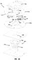
- FIG. 21is a perspective view of an alternate embodiment of a cable spool assembly suitable for use with the fiber optic enclosure of FIG. 8 .
- FIG. 22is an exploded isometric view of the alternate embodiment of the cable spool assembly of FIG. 21 .
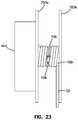
- FIG. 23is a side view of the cable spool assembly of FIG. 21 with a cable strain relief member.
- FIG. 24is a side view of the cable spool assembly of FIG. 21 with an alternate embodiment of a cable strain relief member.
- FIG. 25is a side view of the cable spool assembly of FIG. 21 with an alternate embodiment of a strain relief member.
- FIG. 26is a cross-sectional view of the cable spool assembly of FIG. 25 taken on line 26 - 26 of FIG. 25 .
- FIG. 27is a side view of the cable spool assembly of FIG. 21 with an alternate embodiment of a strain relief member.
- FIG. 28is a cross-sectional view of the cable spool assembly of FIG. 27 taken on line 28 - 28 of FIG. 27 .
- FIG. 29is a cross-sectional view of the mounting assembly of FIG. 21 .
- the fiber optic network 11includes a feeder cable 15 from a central office (not shown).
- the feeder cable 15enters a feeder cable input location 17 (e.g., a fiber distribution hub, a network interface device, etc.) having one or more optical splitters (e.g., 1-to-8 splitters, 1-to-16 splitters, or 1-to-32 splitters) that generate a number of individual fibers.
- a feeder cable input location 17e.g., a fiber distribution hub, a network interface device, etc.
- optical splitterse.g., 1-to-8 splitters, 1-to-16 splitters, or 1-to-32 splitters
- the feeder cable input location 17is not limited to being a fiber distribution hub 17 .
- the fiber distribution hub 17is located on a lower level 19 of the facility 13 .
- Each unit in the facility 13includes a fiber optic enclosure, generally designated 21 , mounted to a structure or mounting location (e.g., a wall, etc.).
- Each of the fiber optic enclosures 21includes a first cable 22 (e.g., a subscriber cable) extending from the fiber optic enclosure 21 to the fiber distribution hub 17 .
- the subscriber cable 22 extending between the fiber distribution hub 17 and the fiber optic enclosure 21typically includes multiple optical fibers.
- each of the fiber optic enclosures 21includes optical connections between an end of the first cable 22 and an end of a second cable 23 .
- the second cable 23extends from the fiber optic enclosure 21 to an end location 24 .
- the end locations 24are disposed in rooms of a unit of the facility 13 .
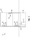
- the fiber optic enclosure 21includes a housing, generally designated 25 having a cover 27 , which is pivotally engaged with the housing 25 .
- the housing 25 and the cover 27from an enclosure 28 .
- the housing 25includes a termination module, generally designated 29 , and a base, generally designated 31 .
- the termination module 29 of the fiber optic enclosure 21serves as the dividing line between incoming fibers of a first cable (e.g., the subscriber cable 22 ) and outgoing fibers of the second cable 23 .
- a first cablee.g., the subscriber cable 22
- the termination module 29will only be briefly described herein.
- the termination module 29includes a frame, generally designated 37 , that includes a plurality of sidewalls 39 .
- two of the sidewalls 39include cable ports 40 which allow fiber optic cables to be routed out of the housing 25 to a desired end location.
- the frame 37has a front portion 41 and a back portion 43 .
- the termination module 29further includes a front panel 45 , a rear panel 47 , and a stepped panel portion, generally designated 48 .
- the front panel 45is generally parallel to the rear panel 47 and is located adjacent the front portion 41 of the frame 37 .
- the stepped panel portion 48extends from the front panel 45 to the rear panel 47 and includes first and second intermediate panels 49 , 51 that are separated by a step 53 .
- the first and second intermediate panels 49 , 51angularly extend between the front panel 45 and the rear panel 47 .
- the first intermediate panel 49defines a termination bank opening 55 and a plurality of termination bank fastener openings 57 , which are disposed adjacent to the termination bank opening 55 .
- a termination bankgenerally designated 59 , is inserted through the termination bank opening 55 and mounted to the first intermediate panel 49 using the termination bank fastener openings 57 .
- the second intermediate panel 51defines a storage bank opening 61 and a plurality of storage bank fastener openings 63 , which are disposed adjacent to the storage bank opening 61 .
- a storage bank 65is inserted through the storage bank opening 61 and mounted to the second intermediate panel 51 using the storage bank fastener openings 63 .
- An exemplary storage bank 65 that is suitable for use with the fiber optic enclosure 21has been described in U.S. Pat. No. 7,218,827, which is hereby incorporated by reference in its entirety.
- the termination bank 59is adapted to receive a plurality of adapters, generally designated 401 .
- the adapters 401are SC-type adapters 401 , although it will be understood that the scope of the present disclosure is not limited to SC-type adapters 401 .
- the SC-type adapter 401was described in U.S. Pat. No. 5,317,663, which is hereby incorporated by reference in its entirety, the SC-type adapter will only be briefly described herein.
- the SC-type adapterincludes a main body 403 with a pair of tabs 405 , 407 located on the exterior of the main body 403 .
- the tabs 405 , 407serve to support the adapter 401 in the termination bank 59 .
- the adapter 401further includes a pair of retaining clips 409 , 411 , with one retaining clip 409 , 411 associated with each tab 405 , 407 .
- a front side 413 of the adapter 401is inserted into the termination bank 59 .
- the retaining clips 409 , 411compress against the main body 403 .
- the adapteris inserted into the termination bank 59 until the tabs 405 , 407 abut the termination bank 59 .
- the retaining clips 409 , 411decompress on the opposite side of the termination bank 59 , thereby retaining the termination bank 59 between the retaining clips 409 , 411 and the tabs 405 , 407 .
- the base 31includes a panel, generally designated 71 , having a front side 73 and a back side 75 .
- the panel 71 of the base 31further includes a plurality of sides 77 .
- the base 31is pivotally engaged to the back portion 43 of one of the sidewalls 39 of the termination module 29 .
- the pivotal engagementis accomplished by a hinge 79 disposed on the back portion 43 of one of the sidewalls 39 of the termination module 29 and one of the sides 77 of the base 31 .
- the pivotal engagement between the termination module 29 and the base 31allows the interface between the termination module 29 and the base 31 to be selectively opened and closed.
- the termination module 29can be pivoted away from the front side 73 of the panel 71 to provide access to the back portion 43 of the termination module 29 .
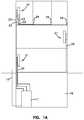
- the closed positionshown schematically in FIG. 7
- the front side 73 of the panel 71 and the interior surfaces of the sidewalls 39 of the frame 37define an interior region 83 of the housing 25 .
- the back side 75 of the base 31 and the outer surfaces of the sidewalls 39 of the frame 37define the exterior surfaces of the housing 25 .
- the panel 71 of the base 31defines a cable passage 85 that extends through the back side 75 and front side 73 .
- the cable passage 85is chamfered with the opening of the cable passage 85 at the front side 73 of the base 31 being larger than the opening of the cable passage 85 at the back side 75 .
- the chamferprovides bend radius protection for cable passing through the cable passage 85 by eliminating perpendicular corners.
- the panel 71further defines a plurality of mounting holes 87 .
- a cable spoolis disposed on the back side 75 of the base 31 such that the cable spool 89 is disposed on the exterior surface of the housing 25 .
- the cable spool 89includes a first axial end 91 , an oppositely disposed second axial end 93 , and a spooling portion 95 disposed between the first and second axial ends 91 , 93 .
- the first axial end 91is rigidly engaged with the back side 75 of the base 31 .
- the rigid engagement of the base 31 and the first axial end 91 of the cable spool 89is provided by a plurality of fasteners 97 (e.g., bolts, screws, rivets, etc.).
- the fasteners 97are countersunk into the first axial end 91 so as not to interfere with the payout of the subscriber cable 22 .
- the fasteners 97extend through the first axial end 91 of the cable spool 89 and through the mounting holes 87 in the panel 71 such that ends of the fasteners are disposed within the interior region 83 of the housing 25 when the base 31 and termination module 29 are in the closed position.
- retainers 99shown in FIG. 6 ), such as nuts, rivet heads, cotter pins, etc., maintain the fasteners 97 in the mounting holes 87 and thereby rigidly retain the cable spool 89 to the back side 75 of the base 31 .
- outer diameters of the first and second axial ends 91 , 93 of the cable spool 89are greater than or equal to a height H of the fiber optic enclosure 21 . In another embodiment, outer diameters of the first and second axial ends 91 , 93 of the cable spool 89 are greater than or equal to a length L of the fiber optic enclosure 21 . In another embodiment, outer diameters of the first and second axial ends 91 , 93 of the cable spool 89 are less than the length L of the fiber optic enclosure 21 . In another embodiment, outer diameters of the first and second axial ends 91 , 93 of the cable spool 89 are less than the height H of the fiber optic enclosure 21 .
- the cable spool 89defines an axial bore 101 that extends through the first and second axial ends 91 , 93 .
- the axial bore 101is adapted to receive a spindle 103 having a central axis 105 .
- the spindle 103includes a mounting plate 107 having a plurality of mounts 109 for mounting the mounting plate 107 to a wall.
- a bearinge.g., a needle bearing, ball bearing, roller bearing, bushing, etc. is disposed between the axial bore 101 and the spindle 103 .
- the subscriber cable 22is coiled around the spooling portion 95 of the cable spool 89 .
- the cable spool 89has an outer circumferential surface 111 having a radius that is greater than the minimum bend radius of the subscriber cable 22 .
- the subscriber cable 22includes a first end 113 (shown in FIG. 6 ), which is inserted through the cable passage 85 (shown in FIG. 6 ) in the panel 71 , and a second end 115 .
- the subscriber cable 22can include multiple optical fibers.
- each of the multiple optical fibers of the first end 113 of the subscriber cable 22would have a connectorized end that is in connected engagement with the rear side of the termination bank 59 .
- the connectorized ends of the subscriber cable 22would be adapted for optical connection with connectorized ends of the second cable 23 (shown in FIG. 1A ).
- the scope of the present disclosureis not limited to the first end 113 having connectorized ends since the optical fibers of the first end 113 of the subscriber cable 22 could be spliced to a plurality of pigtails having connectorized ends.
- the first end 113could be optically connected to the second cable 23 by a splice connection disposed within the enclosure 28 .
- the second end 115 of the subscriber cable 22is configured for connectivity with the fiber distribution hub 17 .
- the length of subscriber cable 22 needed between each of the fiber optic enclosures 21 in the facility 13 and the fiber distribution hub 17will vary depending upon the location of each fiber optic enclosure 21 with respect to the fiber distribution hub 17 .
- the fiber optic enclosure 21provides dual functionality by serving as a storage location for the subscriber cable 22 and by selectively paying out a desired length of the subscriber cable 22 .
- a first length of subscriber cable 22is stored in the fiber optic enclosure 21 by coiling the length of subscriber cable 22 around the cable spool 89 .
- the first length of subscriber cable 22includes an installation length, which is sufficiently long to extend from the mounting location of the enclosure 28 to the fiber distribution hub 17 , and an excess length, which is the length of subscriber cable 22 remaining on the cable spool 89 after the installation length has been paid out.
- the first lengthis greater than or equal to about 100 feet.
- the first length of subscriber cable 22is greater than or equal to about 200 feet.
- the first length of subscriber cable 22is greater than or equal to about 300 feet.
- the first length of subscriber cable 22is greater than or equal to about 400 feet.
- the first length of subscriber cable 22is greater than or equal to about 500 feet. In another embodiment, the first length of subscriber cable 22 is in the range of about 100 to about 2,000 feet. In another embodiment, the first length of subscriber cable 22 is in the range of about 100 to about 1,500 feet. In another embodiment, the first length of subscriber cable 22 is in the range of about 500 to about 1,500 feet. In a preferred embodiment, the first length of subscriber cable 22 , which is coiled around the cable spool 89 , is in the range of 100 to 500 feet. With the cable spool 89 disposed on the exterior surface of the housing 25 , the interior region 83 of the housing 25 can be much more compact since a cable storage area is not required in the interior region 83 . In addition, the fiber optic enclosure 21 with the cable spool 89 can provide more effective cable management for a greater length of subscriber cable 22 than a fiber optic enclosure without the cable spool 89 .
- a second length, or the excess length, of subscriber cable 22is stored around the cable spool 89 after the first length of subscriber cable 22 has been paid out. If the first length of subscriber cable 22 is greater than the installation length of subscriber cable 22 , the second length, or excess length, is stored around the cable spool 89 .
- the second function of the fiber optic enclosure 21involves the selective payout of the subscriber cable 22 .
- the first end 113 of the subscriber cable 22is in connected engagement with the termination bank 59 , which is disposed in the interior region 83 of the housing 25 .
- the first end 113 of the subscriber cable 22is in connected engagement with adapters 401 . Yet, even with this engagement between the first end 113 of the subscriber cable 22 and the termination bank 59 , the subscriber cable 22 can still be paid out without disrupting the connection between the first end 113 and the adapter 401 as the cable spool 89 and the adapters rotate about an axis in unison.
- the cable spool 89is rigidly engaged with the housing 25 and the axial bore 101 of the cable spool 89 is engaged with the spindle 103 such that the cable spool 89 and housing 25 can selectively rotate about the central axis 105 of the spindle 103 . Therefore, with the spindle 103 mounted to the wall and the fiber optic enclosure 21 engaged with the spindle 103 , the desired length of the subscriber cable 22 can be paid out from the fiber optic enclosure 21 by rotating the fiber optic enclosure 21 in a rotational direction 117 (shown as a dashed arrow in FIG. 7 ) about the central axis 105 of the spindle 103 .
- the second end 115 of the subscriber cable 22can be paid out without the first end 113 of the subscriber cable 22 being pulled out of the termination bank 59 .
- the rotation of the fiber optic enclosure 21is ceased.
- the position of the fiber optic enclosure 21can be fixed such that it does not rotate relative to the spindle 103 .
- a pin 119is inserted through an opening 121 in the second axial end 93 of the cable spool 89 and through a corresponding opening 123 in the mounting plate 107 to fix the position of the fiber optic enclosure 21 .
- the fiber optic enclosure 21is fixed in position when the fiber optic enclosure 21 is generally level.
- the fiber optic enclosure 21With the fiber optic enclosure 21 positioned near the fiber distribution hub 17 , the second end 115 of the subscriber cable 22 is unwound from the cable spool 89 . In one embodiment, the second end 115 is optically connected to the fiber distribution hub 17 . With the second end 115 of the subscriber cable 22 optically connected to the fiber distribution hub 17 and the first end 113 of the subscriber cable 22 in connected engagement with the termination bank 59 , the fiber optic enclosure 21 is transported away from the fiber distribution hub 17 . In one embodiment, the fiber optic enclosure 21 is carried away from the fiber distribution hub 17 by an installer.
- the fiber optic enclosure 21is transported away from the fiber distribution hub 17 in a wheeled cart (e.g., dolly, 4-wheeled cart, etc.).
- the fiber optic enclosureis disposed in a packaging enclosure (e.g., a box) during transport.
- a packaging enclosuree.g., a box
- the subscriber cable 22unwinds from the cable spool 89 causing the cable spool 89 and the housing 25 to rotate within the packaging enclosure.
- the fiber optic enclosure 21is removed from the packaging enclosure, mounted to the mounting location and fixed in position.
- the fiber optic enclosure 221includes a housing, generally designated 223 a cable spool, generally designated 227 , a bearing mount, generally designated 229 (shown in FIG. 9 ), and a mounting plate, generally designated 231 .
- the housing 223includes a cover 225 , a base 233 , a first sidewall 235 , and an oppositely disposed second sidewall 237 .
- the first and second sidewalls 235 , 237extend outwardly from the base 233 such that the base 233 and the first and second sidewalls 235 , 237 cooperatively define an interior region 239 .
- a termination module, generally designated 241is disposed in the interior region 239 of the housing 223 .
- the termination module 241 of the fiber optic enclosure 221serves as the dividing line between the incoming fibers and the outgoing fibers.
- the termination module 241is mounted to the base 233 of the housing 223 .
- the termination module 241includes an adapter plate 243 having adapter slots 245 .
- the adapter slots 245are adapted to receive the plurality of adapters 401 (shown in FIGS. 3 and 4 ).
- the base 233 of the housing 223defines a cable passage 247 through which incoming optical fibers pass.
- the interior region 239 of the housing 223includes a slack storage area 249 in which is disposed a plurality of bend radius protectors 251 .
- Each of the bend radius protectors 251is sized such that an outer radius of the bend radius protector 251 is larger than the minimum bend radius of the optical fiber so as to avoid attenuation damage to the optical fibers during storage.
- the cable passage 247is disposed between the slack storage area 249 and the termination module 241 . As incoming optical fibers pass through the cable passage 247 , the incoming optical fibers are routed to the slack storage area 249 .
- Connectorized ends of the incoming optical fibersare then routed from the slack storage area 249 to the front sides 413 of the adapters 401 .
- Connectorized ends of outgoing optical fibersare routed from the back sides of the adapters 401 and through fiber exit ports 253 which are disposed in the first and second sidewalls 235 , 237 .
- the cable spool 227is disposed on an exterior of the housing 223 .
- the cable spool 227is disposed on the back side of the base 233 .
- the cable spool 227includes a first axial end 255 , an oppositely disposed second axial end 257 , and a spooling portion 259 disposed between the first and second axial ends 255 , 257 .
- the first axial end 255is rigidly engaged (i.e., non-rotatable) to the back side of the base 233 .
- the rigid engagement of the base 233 and the first axial end 255 of the cable spool 227is provided by a plurality of fasteners (e.g., bolts, screws, rivets, etc.).
- the fastenersare countersunk into the first axial end 255 so as not to interfere with the payout of a subscriber cable 222 .
- the fastenersextend through the first axial end 255 of the cable spool 227 and through a plurality of mounting holes 261 (shown in FIG. 11 ) in the base 233 such that ends of the fasteners are disposed within the interior region 239 of the housing 223 .
- the fastenersmay be threaded into the base 233 or retained by a plurality of retainers, such as nuts, rivet heads, cotter pins, etc.
- the first axial end 255 of the cable spool 227includes a passage 262 .
- the first axial end 255 of the cable spool 227is mounted to the base 233 such that the passage 262 is aligned with the cable passage 247 .
- incoming optical fiberswhich are coiled around the spooling portion 259 of the cable spool 227 , can enter the housing 223 .
- the bearing mount 229includes a first plate 263 and a second plate 265 .
- each of the first and second plates 263 , 265 of the bearing mount 229includes a central hole 267 having a central axis 269 (shown as a dashed line in FIG. 3 ).
- the first and second plates 263 , 265are connectedly engaged through a bearing, such as a ball bearing.
- the bearingallows the second plate 265 to rotate about the central axis 269 when the first plate 263 is fixed.
- the first plate 263 of the bearing mount 229is rigidly engaged to the second axial end 257 of the cable spool 227 .
- the rigid engagement of the first plate 263 of the bearing mount 229 and the second axial end 257 of the cable spool 227is provided by a plurality of fasteners (e.g., bolts, screws, rivets, etc.).
- the fastenersextend through a plurality of mounting holes 271 in the first plate 263 of the bearing mount 229 and through a plurality of mounting apertures 273 in the second axial end 257 of the cable spool 227 .
- the second plate 265 of the bearing mount 229is rigidly engaged to the mounting plate 231 .
- the mounting plate 231includes a base panel 275 and a plurality of sidewalls 277 that extend outwardly from the base panel 275 .
- the base panel 275includes a plurality of holes 279 for rigidly engaging the base panel 275 to the second plate 265 of the bearing mount 229 .
- a plurality of fastenerse.g., bolts, screws, rivets, etc.
- the base panel 275further includes a plurality of apertures 280 for mounting the fiber optic enclosure 221 to a wall.
- the subscriber cable 22which includes multiple optical fibers, is coiled around the spooling portion 259 of the cable spool 227 .
- the cable spool 227has an outer circumferential surface 281 having a radius that is greater than the minimum bend radius of the subscriber cable 22 .
- the subscriber cable 22includes a first end having connectorized ends, which are inserted through the passage 262 and the cable passage 247 and connectedly engaged with the first end 413 of the adapter 401 .
- the second end of the subscriber cable 22is configured for connectivity with the fiber distribution hub 17 .
- the length of subscriber cable 22 needed between each of the fiber optic enclosures 221 in the facility 13 and the fiber distribution hub 17will vary depending upon the location of each fiber optic enclosure 221 with respect to the fiber distribution hub 17 .
- the first end of the subscriber cable 22is in connected engagement with the termination module 241 , which is disposed in the interior region 239 of the housing 223 .
- the subscriber cable 22With the first end of the subscriber cable 22 in connected engagement with the front sides 413 of the adapters 401 and the outgoing optical fibers disengaged from the back sides of the adapters 401 , the subscriber cable 22 can be paid out.
- the first axial end 255 of the cable spool 227is rigidly engaged to the housing 223 and the second axial end 257 of the cable spool 227 is engaged with the first plate 263 of the bearing mount 229 such that the cable spool 227 and housing 223 can selectively rotate about the central axis 269 of the bearing mount 229 . Therefore, with the second plate 265 of the bearing mount 229 mounted to the mounting plate 231 , which is mounted to a wall, the desired length of the subscriber cable 22 can be paid out from the fiber optic enclosure 221 by rotating the fiber optic enclosure 21 in a rotational direction about the central axis 269 of the bearing mount 229 .
- the second end of the subscriber cable 22can be paid out without the first end of the subscriber cable 22 being pulled out of the termination module 241 .
- the rotation of the fiber optic enclosure 221is ceased. At this point, the position of the fiber optic enclosure 221 can be fixed such that it does not rotate relative to the bearing mount 29 .
- a bracket 283can be used to secure the position of the fiber optic enclosure 221 after the rotation of the fiber optic enclosure 221 has ceased.
- the bracket 283is an L-shaped bracket having an upper portion 285 and a lower portion 287 . It will be understood, however, that the scope of the present disclosure is not limited to the bracket 283 being an L-shaped bracket.
- a plurality of thru-holes 289are defined in the upper and lower portions 285 , 287 of the bracket 283 .
- the thru-holes 289 in the lower portion 287 of the bracket 283align with holes 291 in the sidewalls 277 of the mounting plate 231 while the thru-holes 289 in the upper portion 285 of the bracket 283 align with holes 293 in the first and second sidewalls 235 , 237 .
- fastenersare inserted through the thru-holes 289 in the upper and lower portions 285 , 287 of the bracket 283 and connectedly engaged to the housing 223 and the mounting plate 231 , respectively.
- the cable spool 227is disengaged from the housing 223 .
- the subscriber cable 22is then paid out from the cable spool 227 such that the cable spool 227 rotates about the central axis 259 of the bearing mount 229 .
- the housing 223is then engaged to the first axial end 255 of the cable spool 227 .
- the connectorized ends of the first end of the subscriber cable 22are passed through the passage 262 in the first axial end 255 of the cable spool 227 and through the cable passage 247 in the base 233 of the housing 223 .
- the connectorized ends of the subscriber cable 22disposed in the interior region 239 of the housing 223 , the connectorized ends are connectedly engaged with the first ends 413 of the adapters 401 in the termination module 41 .
- the cable spool 227is uncoupled from the housing 223 such that the cable spool 227 can rotate independently from the housing 223 .
- the connectorized ends of the subscriber cable 22are disengaged from the first ends 413 of the adapters 401 in the termination module 41 .
- the cable spool 227is rotated relative to the housing 223 so as to pay out the subscriber cable 22 .
- the fiber optic enclosure 221is mounted to a mounting location.
- the fiber optic enclosure 221is positioned adjacent to the mounting location.
- the fiber optic enclosure 221is positioned adjacent to the mounting location and disposed in a packaging enclosure (e.g., a box).
- the cable spool 227is coupled to the housing 223 and the connectorized ends of the subscriber cable 22 are engaged to the termination module 41 .
- the fiber optic enclosure 221is then mounted to the mounting location.
- the fiber optic enclosure 421includes a housing, generally designated 423 , a cover 425 , a cable spool, generally designated 427 , the bearing mount 229 , and a mounting plate, generally designated 431 .
- the housing 423includes a base 433 , a first sidewall 435 , and an oppositely disposed second sidewall 437 .
- the first and second sidewalls 435 , 437extend outwardly from the base 433 such that the base 433 and the first and second sidewalls 435 , 437 cooperatively define an interior region 439 .
- a termination moduleis disposed in the interior region 439 of the housing 423 .
- the termination module 441is mounted to the base 433 of the housing 423 .
- the termination module 441includes a plurality of sliding adapter modules 442 . Similar sliding adapter modules 442 have been described in detail in commonly owned U.S. Pat. Nos. 5,497,444; 5,717,810, 6,591,051 and U.S. Pat. Pub. No. 2007/0025675, the disclosures of which are incorporated herein by reference.
- the interior region 439 of the housing 423includes a slack storage area 449 in which is disposed a cable management spool 451 .
- the cable management spool 451includes a passage 447 that extends through the center of the cable management spool 451 and through the base 433 of the housing 423 .
- the passage 447allows the connectorized ends of the subscriber cable 22 to pass into the housing 423 .
- the cable spool 427is disposed on the exterior of the housing 423 .
- the cable spool 427is disposed on the back side of the base 433 .
- the cable spool 427is integrally formed or molded with the housing 423 such that a spooling portion 429 of the cable spool 427 protrudes from the base 433 of the housing 423 .
- the base 433serves both as the base 433 of the housing 423 and as a first axial end of the cable spool 427 .
- the cable spool 427further includes a second axial end 457 , which is oppositely disposed from the base 433 .
- the first plate 263 of the bearing mount 229is rigidly engaged with the second axial end 457 of the cable spool 427 .
- the rigid engagement of the first plate 263 and the second axial end 457is provided by a plurality of fasteners (e.g., bolts, screws, rivets, etc.).
- the fastenersextend through the plurality of mounting holes 271 in the first plate 263 of the bearing mount 229 and through a plurality of mounting apertures 473 in the second axial end 457 of the cable spool 427 .
- the second plate 265 of the bearing mount 229is rigidly engaged with the mounting plate 431 .
- the mounting plate 431includes a base panel 475 having a plurality of holes 479 for rigidly engaging the base panel 475 to the second plate 265 of the bearing mount 229 .
- a plurality of fastenerse.g., bolts, screws, rivets, etc.
- the base panel 475further includes a plurality of apertures 480 for mounting the fiber optic enclosure 421 to a wall.
- a spooling portion of a cable spoolcould provide sidewalls of a housing, where the spooling portion and a base cooperate to define an interior region of the housing.
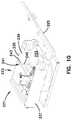
- the fiber optic enclosure 651includes a housing 653 having a first portion 655 and a second portion 656 .
- the first portion 655 and the second portion 656are engaged by a hinge.
- the first portion 655includes a first slack storage area 657 and a termination module 658 .
- the slack storage area 657includes a first plurality of bend radius protectors 659 , which provides organization of the incoming and outgoing cable within the first portion 655 and avoids attenuation damage to the optical fibers during storage, and a first fanout 661 .
- the termination module 658 of the first portion 655includes an adapter module 663 and a second fanout 665 .
- the second portion 656includes a second slack storage area 666 having a second plurality of bend radius protectors 667 and a splice module 669 .
- the splice module 669includes a splice tray 670 for optically connecting optical fibers.
- the cable spool assembly 701Disposed on an exterior surface of the housing 653 is a cable spool assembly 701 .
- the cable spool assembly 701includes a first end 703 a , an oppositely disposed second end 703 b , and a drum portion 705 around which the subscriber cable 22 is coiled or wrapped.
- a first end of the subscriber cable 22is optically connected with the fiber distribution hub 17 .
- the second end of the subscriber cable 22is routed through a first passage 671 in the first portion 655 of the housing 653 and into the first fanout 661 where individual fibers 673 of the subscriber cable 22 are separated from one another.
- the individual fibers 673include connectorized ends that are routed and connected to a first side of the adapter module 663 .
- Connectorized ends of individual fibers 675 of a drop cable 677are connected to a second side of the adapter module 663 and routed to the second fanout 665 where the individual fibers 675 are rejoined into the drop cable 677 .
- the drop cable 677is then routed through a second passage 679 into the second portion 656 of the housing 653 .
- the drop cable 677is routed around the second plurality of bend radius protectors 667 and into the splice tray 670 of the splice module 669 where the drop cable 677 can be connected with a first end of the second cable 23 , where the second end of the second cable is adapted for connection at the end location in the facility 13 (shown schematically in FIG. 1 ).
- the first end of the subscriber cable 22is paid out from the cable spool assembly 701 and routed to the fiber distribution hub 17 .
- a cable strain relief member 735is disposed along an intermediate portion of the subscriber cable 22 between the first and second ends of the subscriber cable.
- the cable strain relief member 735is adapted to relieve tensile forces that can act on the connectorized ends of the second end of the subscriber cable 22 , which are connected to the first side of the adapter module 663 inside the housing 653 of the fiber optic enclosure 651 , when an installer tries to pull more subscriber cable 22 from the cable spool assembly 701 than is available.
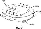
- the cable spool assembly 701is shown.
- the first and second spool ends 703 a , 703 b of the cable spool assembly 701are substantially similar.
- the first and second ends 703 a , 703 b in the subject embodimentare substantially similar, the first and second ends 703 a , 703 b shall be referred to as spool end 703 in both singular and plural tense as required by context. It will be understood, however, that the scope of the present disclosure is not limited to the first and second ends 703 a , 703 b being substantially similar.
- Each spool end 703is adapted to be a tear-away end. As a tear-away ends, the spool end 703 includes a line of weakness 709 . In the subject embodiment, the line of weakness 709 extends from an inner diameter 711 of the spool end 703 to an outer diameter 713 of the spool end 703 .
- Each of the spool ends 703defines an access notch 715 that extends outwardly in a radial direction from the inner diameter 711 and a tab 717 that extends inwardly in a radial direction.
- the access notch 715is adapted to provide access to cable wound around the drum portion 705 of the cable spool assembly 701 .
- the access notch 715is also adapted to provide a location through which the subscriber cable 22 can pass to get access to the passage 447 in the housing 223 of the fiber optic enclosure 421 .
- the tab 717is adapted for engagement with the drum portion 705 in order to prevent rotation of the spool ends 703 relative to the drum portion 705 .
- the drum portion 705is generally cylindrical in shape and includes a first axial end 719 and an oppositely disposed second axial end 721 .
- the first axial end 719is disposed adjacent to a bracket 722 that is adapted to receive the housing 423 while the second axial end 721 is disposed adjacent to the mounting assembly 707 .
- the drum portionfurther includes an inner bore 723 and an outer surface 725 .
- each of the first and second axial ends 719 , 721defines a groove 727 .
- each groove 727extends from the inner bore 723 through the outer surface 725 and is adapted to receive the tab 717 from one of the spool ends 703 .
- the engagement of the tab 717 of spool end 703 in the groove 727 of the drum portion 705prevents rotation of the spool end 703 relative to the drum portion 705 .
- the second axial end 721further defines a notch 729 .
- the notch 729extends from the inner bore 723 through the outer surface 725 and is disposed on the second axial end 721 opposite the groove 727 on the second axial end 721 .
- the notch 729is adapted to engage a protrusion 731 on a first plate 733 of the mounting assembly 707 .
- the engagement of the notch 729 and the protrusion 731 of the first plate 733 of the mounting assembly 707prevents relative rotation between the drum portion 705 and the first plate 733 of the mounting assembly 707 .
- the drum portion 705is adapted to receive the cable strain relief member 735 .
- the cable strain relief member 735is adapted to relieve tensile forces that can act on the connectorized ends of the subscriber cable 22 , which are connected to the adapter modules 441 inside the housing 423 of the fiber optic enclosure 421 , when an installer tries to pull more subscriber cable 22 from the cable spool assembly 701 than is available.
- the cable strain relief member 735reduces this force acting on the connectorized ends of the subscriber cable 22 by redirecting the force through the cable strain relief member 735 to the drum portion 705 of the cable spool assembly 701 .
- the cable strain relief member 735is a cable tie. In another embodiment, the cable strain relief member 735 is a strip of adhesive. In another embodiment, the cable strain relief member 735 is a protrusion that extends outwardly from the drum portion 705 .
- the outer surface 725 of the drum portion 705includes a plurality of thru-holes 737 . It will be understood, however, that the scope of the present disclosure is not limited to the outer surface 725 including a plurality of thru-holes 737 . In the subject embodiment, and by way of example only, there are three thru-holes 737 disposed in the outer surface 725 of the drum portion 705 . The thru-holes 737 are adapted to receive the cable strain relief member 735 . In subject embodiment, the cable strain relief member 735 is a cable tie 735 .
- the strain relief arrangement 739secures a portion of the subscriber cable 22 to the drum portion 705 of the cable spool assembly 701 .
- the strain relief arrangement 739secures the portion of the subscriber cable 22 to the drum portion 705 of the cable spool assembly 701 with the cable strain relief member 735 .
- the cable strain relief member 735is the cable tie 735 .
- a first end 741 (shown in FIG. 22 ) of the cable tie 735is inserted through one of the plurality of thru-holes 737 (shown in FIG. 22 ) in the outer surface 725 of the drum portion 705 while a second end 743 (shown in FIG. 22 ) of the cable tie 735 is inserted through another of the plurality of thru-holes 737 .
- a first layer of subscriber cable 22can be coiled or wound around the drum portion 705 .
- the first layer of subscriber cable 22is a layer that is immediately adjacent to the outer surface 725 of the drum portion 705 .
- the first and second ends 741 , 743 of the cable tie 735are secured together around the subscriber cable 22 .
- the cable tie 735secures a single row in the first layer of the subscriber cable 22 .
- the cable tie 735is secured around a sleeve 803 .
- the sleeve 803is disposed around a portion of the subscriber cable 22 .
- the sleeve 803can be a semi-rigid piece of tubing, such as tubing commercially available under the brand name TYGON® or any pneumatic tubing.
- the sleeve 803includes a longitudinal slit 805 through which the subscriber cable 22 can be inserted into the sleeve 803 .
- the sleeve 803protects the subscriber cable 22 from potential over tightening of the cable tie 735 .
- the sleeve 803can serve as a bend radius protector for the portion of the subscriber cable 22 secured by the cable tie 735 .
- the cable tie 735secures a portion of the subscriber cable 22 to the drum portion 705 .
- the sleeve 803reduces the risk of the subscriber cable 22 bending beyond the minimum bend radius of the cable at the location of the cable tie 735 .
- the strain relief arrangement 901includes a strain relief member 903 .
- the strain relief member 903is an adhesive sheet 903 having a high-strength adhesive on at least one side.
- the adhesive sheet 903includes a first side 905 and an oppositely disposed second side 907 .
- only the first side 905includes an adhesive layer.
- the first and second sides 905 , 907include an adhesive layer.
- a suitable example of an adhesive sheet 903 having an adhesive layer on the first and second sides 905 , 907is produced by 3M under the brand VHBTM Tape 4932 .
- the adhesive sheet 903further includes a first end portion 909 and an oppositely disposed second end portion 911 .
- the first side 605 of the first and second end portions 909 , 911 of the adhesive sheet 903is adapted for affixation to the outer surface 725 of the drum portion 705 .
- a portion of the first side 905is adapted for affixation to the portion of the subscriber cable 22 .
- the remaining subscriber cable 22is coiled or wrapped around the drum portion 705 .
- the remaining subscriber cable 22 that is positioned over the second end portion 911 of the second side 907is releasably affixed to the drum portion 705 .
- This releasable affixation of the remaining portion of the subscriber cable 22 to the second side 907 of the adhesive sheet 903decreases the spinning speed of the cable spool assembly 701 as the subscriber cable 22 approaches its total payout length by providing resistance to the removal of that remaining portion of the subscriber cable 22 from the drum portion 705 .
- the adhesive strain relief arrangement 1001includes a first adhesive sheet 1003 and a second adhesive sheet 1005 .
- the first adhesive sheet 1003includes a first adhesive side 1007 , which is disposed immediately adjacent to the outer surface 725 of the drum portion 705 , and an oppositely disposed second adhesive side 1009 .
- An inner portion of the first layer of subscriber cable 22 that is coiled or wrapped around the drum portion 705is disposed on the second adhesive side 1009 and releasably affixed to the second adhesive side 1009 .
- This releasable affixation of the portion of the first layer of the subscriber cable 22 to the second adhesive side 1009 of the adhesive sheet 1003decreases the spinning speed of the cable spool assembly 701 as the subscriber cable 22 approaches its total payout length by providing resistance to the removal of that remaining portion of the subscriber cable 22 from the drum portion 705 .
- the second adhesive sheet 1005With the first layer of subscriber cable 22 coiled or wound around the drum portion 705 of the cable spool assembly 701 , the second adhesive sheet 1005 , having at least one side with an adhesive layer, is adhered to an outer portion of the first layer of subscriber cable 22 . In one embodiment, the second adhesive sheet 1005 is angularly offset from the first adhesive sheet 1003 .
- the mounting assembly 707includes the first plate 733 , a second plate 751 , and a bearing assembly 753 .
- the bearing assembly 753is a simple or plain bearing. It will be understood, however, that the bearing assembly 753 is not limited to being a simple or plain bearing.
- the bearing assembly 753includes a ring member 755 and a puck member 757 .
- the bearing assembly 753is manufactured from a general purpose polycarbonate material.
- the bearing assemblyis molded from a thermoplastic polyester resin, such as Valox resins.
- the ring member 755includes a first surface 759 , an oppositely disposed second surface 761 .
- the first and second surfaces 759 , 761are generally planar.
- the second surface 761is adapted for engagement with the second plate 751 of the mounting assembly 707 .
- the ring member 755defines an inner bore 763 having a bearing surface 765 .
- the bearing surface 765is disposed at angle ⁇ , which is measured from the second surface 761 as shown in FIG. 29 .
- the angle ⁇is an oblique angle less than about 90 degrees.
- the angle ⁇is in the range of about 30 degrees to about 75 degrees.
- the angle ⁇is in the range of about 45 degrees to about 60 degrees.
- the puck member 757includes a first end surface 767 , an oppositely disposed second end surface 769 , and a mating bearing surface 771 .
- the first and second end surfaces 767 , 769are generally planar.
- the first end surface 767is adapted for engagement with the first plate 733 of the mounting assembly 707 .
- the mating bearing surface 771is adapted to engage the bearing surface 765 of the ring member 755 in sliding contact.
- the mating bearing surface 771is disposed at an angle ⁇ , which is measured from the plane in which the second end surface 769 is disposed as shown in FIG. 29 .
- the angle ⁇is about equal to the angle ⁇ .
- the angle ⁇is an oblique angle less than about 90 degrees.
- the angle ⁇is in the range of about 30 degrees to about 75 degrees.
- the angle ⁇is in the range of about 45 degrees to about 60 degrees.
- an outer periphery of the puck member 757is sized slightly smaller than the inner bore 763 of the ring member 755 . This difference in size between the outer periphery of the puck member 757 and the inner bore 763 of the ring member 755 creates a clearance 773 between the ring member 755 and the puck member 757 .
- This clearance 773allows for rotation of the puck member 757 in the ring member 755 following dimensional expansion of the outer periphery of the puck member 757 , which results from heat generated from rotation of the puck member 757 in the ring member 755 .
- the clearance 773is filled with silicon grease or other lubricant to reduce the amount of heat generated.
Landscapes
- Physics & Mathematics (AREA)
- General Physics & Mathematics (AREA)
- Optics & Photonics (AREA)
- Engineering & Computer Science (AREA)
- Civil Engineering (AREA)
- Structural Engineering (AREA)
- Light Guides In General And Applications Therefor (AREA)
- Mechanical Coupling Of Light Guides (AREA)
- Optical Couplings Of Light Guides (AREA)
Abstract
Description
Claims (10)
Priority Applications (1)
| Application Number | Priority Date | Filing Date | Title |
|---|---|---|---|
| US16/185,315US10627592B2 (en) | 2007-05-07 | 2018-11-09 | Fiber optic assembly with cable spool |
Applications Claiming Priority (10)
| Application Number | Priority Date | Filing Date | Title |
|---|---|---|---|
| US91649507P | 2007-05-07 | 2007-05-07 | |
| US95421007P | 2007-08-06 | 2007-08-06 | |
| US3722308P | 2008-03-17 | 2008-03-17 | |
| US12/113,786US7715679B2 (en) | 2007-05-07 | 2008-05-01 | Fiber optic enclosure with external cable spool |
| US12/715,855US8131126B2 (en) | 2007-05-07 | 2010-03-02 | Fiber optic enclosure with external cable spool |
| US13/348,133US8380035B2 (en) | 2007-05-07 | 2012-01-11 | Fiber optic enclosure with external cable spool |
| US13/743,967US9057860B2 (en) | 2007-05-07 | 2013-01-17 | Fiber optic enclosure with external cable spool |
| US14/703,446US9535227B2 (en) | 2007-05-07 | 2015-05-04 | Fiber optic cable spool assembly |
| US15/388,874US11009671B2 (en) | 2007-05-07 | 2016-12-22 | Fiber optic assembly with cable storage arrangement |
| US16/185,315US10627592B2 (en) | 2007-05-07 | 2018-11-09 | Fiber optic assembly with cable spool |
Related Parent Applications (1)
| Application Number | Title | Priority Date | Filing Date |
|---|---|---|---|
| US15/388,874ContinuationUS11009671B2 (en) | 2007-05-07 | 2016-12-22 | Fiber optic assembly with cable storage arrangement |
Publications (2)
| Publication Number | Publication Date |
|---|---|
| US20190079258A1 US20190079258A1 (en) | 2019-03-14 |
| US10627592B2true US10627592B2 (en) | 2020-04-21 |
Family
ID=39643825
Family Applications (11)
| Application Number | Title | Priority Date | Filing Date |
|---|---|---|---|
| US12/113,786ActiveUS7715679B2 (en) | 2007-05-07 | 2008-05-01 | Fiber optic enclosure with external cable spool |
| US12/715,855Expired - Fee RelatedUS8131126B2 (en) | 2007-05-07 | 2010-03-02 | Fiber optic enclosure with external cable spool |
| US13/348,133Expired - Fee RelatedUS8380035B2 (en) | 2007-05-07 | 2012-01-11 | Fiber optic enclosure with external cable spool |
| US13/743,967Active2028-06-26US9057860B2 (en) | 2007-05-07 | 2013-01-17 | Fiber optic enclosure with external cable spool |
| US14/703,446ActiveUS9535227B2 (en) | 2007-05-07 | 2015-05-04 | Fiber optic cable spool assembly |
| US15/388,874ActiveUS11009671B2 (en) | 2007-05-07 | 2016-12-22 | Fiber optic assembly with cable storage arrangement |
| US16/185,315ActiveUS10627592B2 (en) | 2007-05-07 | 2018-11-09 | Fiber optic assembly with cable spool |
| US16/196,166ActiveUS10788642B2 (en) | 2007-05-07 | 2018-11-20 | Fiber optic assembly with cable storage arrangement |
| US17/238,591AbandonedUS20210302682A1 (en) | 2007-05-07 | 2021-04-23 | Fiber optic enclosure with external cable spool |
| US18/482,048ActiveUS12235506B2 (en) | 2007-05-07 | 2023-10-06 | Fiber optic enclosure with external cable spool |
| US19/027,779PendingUS20250237839A1 (en) | 2007-05-07 | 2025-01-17 | Fiber optic enclosure with external cable spool |
Family Applications Before (6)
| Application Number | Title | Priority Date | Filing Date |
|---|---|---|---|
| US12/113,786ActiveUS7715679B2 (en) | 2007-05-07 | 2008-05-01 | Fiber optic enclosure with external cable spool |
| US12/715,855Expired - Fee RelatedUS8131126B2 (en) | 2007-05-07 | 2010-03-02 | Fiber optic enclosure with external cable spool |
| US13/348,133Expired - Fee RelatedUS8380035B2 (en) | 2007-05-07 | 2012-01-11 | Fiber optic enclosure with external cable spool |
| US13/743,967Active2028-06-26US9057860B2 (en) | 2007-05-07 | 2013-01-17 | Fiber optic enclosure with external cable spool |
| US14/703,446ActiveUS9535227B2 (en) | 2007-05-07 | 2015-05-04 | Fiber optic cable spool assembly |
| US15/388,874ActiveUS11009671B2 (en) | 2007-05-07 | 2016-12-22 | Fiber optic assembly with cable storage arrangement |
Family Applications After (4)
| Application Number | Title | Priority Date | Filing Date |
|---|---|---|---|
| US16/196,166ActiveUS10788642B2 (en) | 2007-05-07 | 2018-11-20 | Fiber optic assembly with cable storage arrangement |
| US17/238,591AbandonedUS20210302682A1 (en) | 2007-05-07 | 2021-04-23 | Fiber optic enclosure with external cable spool |
| US18/482,048ActiveUS12235506B2 (en) | 2007-05-07 | 2023-10-06 | Fiber optic enclosure with external cable spool |
| US19/027,779PendingUS20250237839A1 (en) | 2007-05-07 | 2025-01-17 | Fiber optic enclosure with external cable spool |
Country Status (10)
| Country | Link |
|---|---|
| US (11) | US7715679B2 (en) |
| EP (1) | EP2149062B1 (en) |
| CN (3) | CN103592733B (en) |
| AR (1) | AR066464A1 (en) |
| AU (4) | AU2008247361B2 (en) |
| BR (1) | BRPI0811443B1 (en) |
| ES (1) | ES2820295T3 (en) |
| MX (1) | MX2009011976A (en) |
| TW (1) | TWI457627B (en) |
| WO (1) | WO2008137894A1 (en) |
Cited By (3)
| Publication number | Priority date | Publication date | Assignee | Title |
|---|---|---|---|---|
| US20240159984A1 (en)* | 2022-11-14 | 2024-05-16 | Jiangsu SUMEC Electromechanical Co., Ltd. | Optical cable assembly and optical cable testing method |
| US12019301B2 (en) | 2007-08-06 | 2024-06-25 | Commscope Technologies Llc | Fiber optic enclosure with internal cable spool |
| US12235506B2 (en) | 2007-05-07 | 2025-02-25 | Commscope Technologies Llc | Fiber optic enclosure with external cable spool |
Families Citing this family (153)
| Publication number | Priority date | Publication date | Assignee | Title |
|---|---|---|---|---|
| US7748660B2 (en)* | 2007-06-22 | 2010-07-06 | Ofs Fitel, Llc | Fiber optic rapid spooling tool |
| US7869682B2 (en) | 2007-09-05 | 2011-01-11 | Adc Telecommunications, Inc. | Fiber optic enclosure with tear-away spool |
| US8798427B2 (en) | 2007-09-05 | 2014-08-05 | Corning Cable Systems Llc | Fiber optic terminal assembly |
| AU2013242864B2 (en)* | 2007-09-05 | 2015-07-09 | Commscope Technologies Llc | Fiber optic enclosure with tear-away spool |
| US8254740B2 (en) | 2008-06-19 | 2012-08-28 | Adc Telecommunications, Inc. | Methods and systems for distributing fiber optic telecommunications services to local area |
| US8184938B2 (en) | 2008-08-29 | 2012-05-22 | Corning Cable Systems Llc | Rear-installable fiber optic modules and equipment |
| US11294136B2 (en) | 2008-08-29 | 2022-04-05 | Corning Optical Communications LLC | High density and bandwidth fiber optic apparatuses and related equipment and methods |
| US8452148B2 (en) | 2008-08-29 | 2013-05-28 | Corning Cable Systems Llc | Independently translatable modules and fiber optic equipment trays in fiber optic equipment |
| WO2010028519A1 (en)* | 2008-09-09 | 2010-03-18 | Lin Kevin | Heating control device and method thereof |
| US8265447B2 (en)* | 2008-09-16 | 2012-09-11 | Adc Telecommunications, Inc. | Modular fiber optic enclosure with external cable spool |
| CN102209921B (en) | 2008-10-09 | 2015-11-25 | 康宁光缆系统有限公司 | There is the fibre-optic terminus supported from the adapter panel of the input and output optical fiber of optical splitters |
| US8879882B2 (en) | 2008-10-27 | 2014-11-04 | Corning Cable Systems Llc | Variably configurable and modular local convergence point |
| US8903215B2 (en) | 2008-12-31 | 2014-12-02 | Opterna Technology Limited | Enclosure-less fiber optic terminals |
| US8081857B2 (en)* | 2008-12-31 | 2011-12-20 | Opterna Am, Inc. | System for an internal rotating storage spool combined with top and bottom cable access in a fiber distribution terminal |
| EP2221932B1 (en) | 2009-02-24 | 2011-11-16 | CCS Technology Inc. | Holding device for a cable or an assembly for use with a cable |
| US8699838B2 (en) | 2009-05-14 | 2014-04-15 | Ccs Technology, Inc. | Fiber optic furcation module |
| US9075216B2 (en) | 2009-05-21 | 2015-07-07 | Corning Cable Systems Llc | Fiber optic housings configured to accommodate fiber optic modules/cassettes and fiber optic panels, and related components and methods |
| US8538226B2 (en) | 2009-05-21 | 2013-09-17 | Corning Cable Systems Llc | Fiber optic equipment guides and rails configured with stopping position(s), and related equipment and methods |
| WO2010148325A1 (en) | 2009-06-19 | 2010-12-23 | Corning Cable Systems Llc | High fiber optic cable packing density apparatus |
| US8712206B2 (en) | 2009-06-19 | 2014-04-29 | Corning Cable Systems Llc | High-density fiber optic modules and module housings and related equipment |
| EP2443497B1 (en) | 2009-06-19 | 2020-03-04 | Corning Cable Systems LLC | High density and bandwidth fiber optic apparatus |
| KR101820175B1 (en) | 2009-07-21 | 2018-01-18 | 콤스코프 커넥티비티 엘엘씨 | Rapid universal rack mount enclosure |
| US8238707B2 (en) | 2009-07-30 | 2012-08-07 | Adc Telecommunications, Inc. | Locking spool for telecommunications cable and method |
| US8474742B2 (en)* | 2009-07-30 | 2013-07-02 | Adc Telecommunications, Inc. | Spool for telecommunications cable and method |
| US8428419B2 (en)* | 2009-09-23 | 2013-04-23 | Adc Telecommunications, Inc. | Fiber distribution hub with internal cable spool |
| US8515234B2 (en)* | 2009-11-25 | 2013-08-20 | Adc Telecommunications, Inc. | Methods, systems and devices for providing fiber-to-the-desktop |
| US8208781B1 (en)* | 2009-12-03 | 2012-06-26 | Adtran, Inc. | Fiber optic connector panel |
| US8625950B2 (en) | 2009-12-18 | 2014-01-07 | Corning Cable Systems Llc | Rotary locking apparatus for fiber optic equipment trays and related methods |
| EP2531877B9 (en)* | 2010-02-02 | 2016-07-13 | ADC Telecommunications, Inc. | Fiber optic cable bundle with staggered connectors |
| US8992099B2 (en) | 2010-02-04 | 2015-03-31 | Corning Cable Systems Llc | Optical interface cards, assemblies, and related methods, suited for installation and use in antenna system equipment |
| EP2545402B1 (en) | 2010-03-11 | 2018-05-23 | ADC Telecommunications, Inc. | Fiber optic enclosure with internal cable spool assembly |
| US9547144B2 (en)* | 2010-03-16 | 2017-01-17 | Corning Optical Communications LLC | Fiber optic distribution network for multiple dwelling units |
| CN102792205B (en)* | 2010-03-16 | 2016-03-16 | 康宁光缆系统有限公司 | Fiber optic distribution network for multi-storey residential units |
| US8913866B2 (en) | 2010-03-26 | 2014-12-16 | Corning Cable Systems Llc | Movable adapter panel |
| US9078287B2 (en) | 2010-04-14 | 2015-07-07 | Adc Telecommunications, Inc. | Fiber to the antenna |
| US8837940B2 (en) | 2010-04-14 | 2014-09-16 | Adc Telecommunications, Inc. | Methods and systems for distributing fiber optic telecommunication services to local areas and for supporting distributed antenna systems |
| CA2796221C (en) | 2010-04-16 | 2018-02-13 | Ccs Technology, Inc. | Sealing and strain relief device for data cables |
| US8792767B2 (en) | 2010-04-16 | 2014-07-29 | Ccs Technology, Inc. | Distribution device |
| EP2381284B1 (en) | 2010-04-23 | 2014-12-31 | CCS Technology Inc. | Under floor fiber optic distribution device |
| US8879881B2 (en) | 2010-04-30 | 2014-11-04 | Corning Cable Systems Llc | Rotatable routing guide and assembly |
| US8705926B2 (en) | 2010-04-30 | 2014-04-22 | Corning Optical Communications LLC | Fiber optic housings having a removable top, and related components and methods |
| US9075217B2 (en) | 2010-04-30 | 2015-07-07 | Corning Cable Systems Llc | Apparatuses and related components and methods for expanding capacity of fiber optic housings |
| US9632270B2 (en) | 2010-04-30 | 2017-04-25 | Corning Optical Communications LLC | Fiber optic housings configured for tool-less assembly, and related components and methods |
| US9720195B2 (en) | 2010-04-30 | 2017-08-01 | Corning Optical Communications LLC | Apparatuses and related components and methods for attachment and release of fiber optic housings to and from an equipment rack |
| US8660397B2 (en) | 2010-04-30 | 2014-02-25 | Corning Cable Systems Llc | Multi-layer module |
| US9519118B2 (en) | 2010-04-30 | 2016-12-13 | Corning Optical Communications LLC | Removable fiber management sections for fiber optic housings, and related components and methods |
| WO2011146717A2 (en) | 2010-05-19 | 2011-11-24 | Adc Telecommunications, Inc. | Lashing together multiple fiber optic telecommunications cables |
| AU2010355632B2 (en)* | 2010-06-18 | 2014-09-18 | Adc Communications (Shanghai) Co., Ltd. | Fiber optic distribution terminal and method of deploying fiber distribution cable |
| CN110174737A (en) | 2010-06-23 | 2019-08-27 | Adc电信公司 | Telecommunication assembly |
| US8792766B2 (en) | 2010-07-20 | 2014-07-29 | Ofs Fitel, Llc | Tool for routing an optical fiber or cable at a living unit of customer premises |
| EP2567271B1 (en) | 2010-07-20 | 2016-10-12 | Ofs Fitel Llc | Optical fiber installation at customer premises |
| WO2012018787A2 (en) | 2010-08-02 | 2012-02-09 | Adc Telecommunications, Inc. | Cable spool assembly |
| US8718436B2 (en) | 2010-08-30 | 2014-05-06 | Corning Cable Systems Llc | Methods, apparatuses for providing secure fiber optic connections |
| WO2012054454A2 (en) | 2010-10-19 | 2012-04-26 | Corning Cable Systems Llc | Transition box for multiple dwelling unit fiber optic distribution network |
| CA2814954A1 (en)* | 2010-10-19 | 2012-04-26 | Corning Cable Systems Llc | Collapsible cable reel |
| US9279951B2 (en) | 2010-10-27 | 2016-03-08 | Corning Cable Systems Llc | Fiber optic module for limited space applications having a partially sealed module sub-assembly |
| US8662760B2 (en) | 2010-10-29 | 2014-03-04 | Corning Cable Systems Llc | Fiber optic connector employing optical fiber guide member |
| US9116324B2 (en) | 2010-10-29 | 2015-08-25 | Corning Cable Systems Llc | Stacked fiber optic modules and fiber optic equipment configured to support stacked fiber optic modules |
| CA2819235C (en) | 2010-11-30 | 2018-01-16 | Corning Cable Systems Llc | Fiber device holder and strain relief device |
| US8873922B2 (en) | 2010-12-20 | 2014-10-28 | Adc Telecommunications, Inc. | Fan-out and parking module |
| WO2012106510A2 (en) | 2011-02-02 | 2012-08-09 | Corning Cable Systems Llc | Dense fiber optic connector assemblies and related connectors and cables suitable for establishing optical connections for optical backplanes in equipment racks |
| US8720810B2 (en) | 2011-02-11 | 2014-05-13 | Adc Telecommunications, Inc. | Spool for telecommunications cable and method |
| TWM414753U (en)* | 2011-04-08 | 2011-10-21 | Askey Computer Corp | Optical-fiber communication device |
| US9008485B2 (en) | 2011-05-09 | 2015-04-14 | Corning Cable Systems Llc | Attachment mechanisms employed to attach a rear housing section to a fiber optic housing, and related assemblies and methods |
| CA2834781C (en) | 2011-05-13 | 2019-02-05 | Corning Cable Systems Llc | Transformable cable reels and related assemblies and methods |
| JP5673353B2 (en)* | 2011-05-26 | 2015-02-18 | オムロン株式会社 | Fiber holder and fiber laser device |
| CA2877896C (en) | 2011-06-24 | 2020-07-21 | Adc Telecommunications, Inc. | Fiber termination enclosure with modular plate assemblies |
| AU2012275598A1 (en) | 2011-06-30 | 2014-01-16 | Corning Optical Communications LLC | Fiber optic equipment assemblies employing non-U-width-sized housings and related methods |
| US8953924B2 (en) | 2011-09-02 | 2015-02-10 | Corning Cable Systems Llc | Removable strain relief brackets for securing fiber optic cables and/or optical fibers to fiber optic equipment, and related assemblies and methods |
| WO2013039783A2 (en) | 2011-09-16 | 2013-03-21 | Adc Telecommunciations, Inc. | Fiber optic cable packaging management |
| US8913867B2 (en) | 2011-11-21 | 2014-12-16 | Opterna Technology Limited | Fiber optic collector and terminal assemblies |
| WO2013078322A2 (en)* | 2011-11-21 | 2013-05-30 | Opterna Am, Inc. | Enclosure-less fiber optic terminals and adapter retaining systems |
| US8886005B2 (en) | 2012-02-13 | 2014-11-11 | Opterna Technology Limited | Adapter retaining systems |
| US9038832B2 (en) | 2011-11-30 | 2015-05-26 | Corning Cable Systems Llc | Adapter panel support assembly |
| US9219546B2 (en) | 2011-12-12 | 2015-12-22 | Corning Optical Communications LLC | Extremely high frequency (EHF) distributed antenna systems, and related components and methods |
| US9188760B2 (en)* | 2011-12-22 | 2015-11-17 | Adc Telecommunications, Inc. | Mini rapid delivery spool |
| US9329352B2 (en) | 2012-01-12 | 2016-05-03 | Corning Cable Systems Llc | Slack cable storage apparatus |
| US9036974B2 (en) | 2012-01-19 | 2015-05-19 | Adc Telecommunications, Inc. | Fiber optic enclosure with tear-away spool |
| US9494757B2 (en)* | 2012-02-29 | 2016-11-15 | Commscope Technologies Llc | Fiber optic cable packaging arrangement |
| US10110307B2 (en) | 2012-03-02 | 2018-10-23 | Corning Optical Communications LLC | Optical network units (ONUs) for high bandwidth connectivity, and related components and methods |
| WO2013165899A1 (en) | 2012-04-30 | 2013-11-07 | Adc Telecommunications, Inc. | Cable payout cassette with single layer cable storage area |
| US9126802B2 (en) | 2012-04-30 | 2015-09-08 | Adc Telecommunications, Inc. | Payout spool with automatic cable disconnect/reconnect |
| CN104412475B (en) | 2012-04-30 | 2019-01-15 | Adc电信公司 | Cable storage spool with center feed |
| US9722407B2 (en) | 2012-04-30 | 2017-08-01 | Commscope Technologies Llc | Guided cable storage assembly with switchbacks |
| US9004778B2 (en) | 2012-06-29 | 2015-04-14 | Corning Cable Systems Llc | Indexable optical fiber connectors and optical fiber connector arrays |
| US9250409B2 (en) | 2012-07-02 | 2016-02-02 | Corning Cable Systems Llc | Fiber-optic-module trays and drawers for fiber-optic equipment |
| CN106707434B (en)* | 2012-08-07 | 2019-06-11 | 爱德奇电讯国际贸易(上海)有限公司 | Fibre junction component |
| US9049500B2 (en) | 2012-08-31 | 2015-06-02 | Corning Cable Systems Llc | Fiber optic terminals, systems, and methods for network service management |
| US9042702B2 (en) | 2012-09-18 | 2015-05-26 | Corning Cable Systems Llc | Platforms and systems for fiber optic cable attachment |
| US8909019B2 (en) | 2012-10-11 | 2014-12-09 | Ccs Technology, Inc. | System comprising a plurality of distribution devices and distribution device |
| ES2551077T3 (en) | 2012-10-26 | 2015-11-16 | Ccs Technology, Inc. | Fiber optic management unit and fiber optic distribution device |
| WO2014072368A1 (en) | 2012-11-07 | 2014-05-15 | Tyco Electronics Raychem Bvba | Rapid distribution terminal |
| EP2917775B1 (en) | 2012-11-07 | 2019-06-05 | CommScope Connectivity Belgium BVBA | Cable over-length storage system |
| ES1141660Y (en) | 2012-12-19 | 2015-10-14 | Tyco Electronics Raychem Bvba | Distribution device with incrementally added dividers |
| US9327938B2 (en) | 2013-02-14 | 2016-05-03 | Haworth, Inc. | Cable retractor |
| US8985862B2 (en) | 2013-02-28 | 2015-03-24 | Corning Cable Systems Llc | High-density multi-fiber adapter housings |
| US9537718B2 (en) | 2013-03-15 | 2017-01-03 | Cisco Technology, Inc. | Segment routing over label distribution protocol |
| CN103499858B (en)* | 2013-09-27 | 2015-07-22 | 中国矿业大学 | Optical fiber releasing device of underground coal mine mobile equipment |
| US20150093088A1 (en)* | 2013-09-30 | 2015-04-02 | Optema Technology Limited | Fiber Optic Terminal Assemblies |
| WO2015067645A1 (en)* | 2013-11-06 | 2015-05-14 | Adc Czech Republic, S.R.O. | Fiber termination point with overlength storage |
| US9891399B2 (en)* | 2013-11-12 | 2018-02-13 | Commscope Technologies Llc | Packaging assembly for telecommunications components |
| US9459425B2 (en)* | 2013-12-20 | 2016-10-04 | Google Inc. | Spooling cable |
| US9762488B2 (en) | 2014-03-06 | 2017-09-12 | Cisco Technology, Inc. | Segment routing extension headers |
| US9500814B2 (en)* | 2014-03-26 | 2016-11-22 | Commscope Technologies Llc | Optical adapter module with managed connectivity |
| US10203465B2 (en)* | 2014-04-25 | 2019-02-12 | Commscope Technologies Llc | Managed connectivity in cable spool assemblies |
| AT515664B1 (en)* | 2014-05-20 | 2015-11-15 | Hofstätter Josef | Insertion element for frame racks |
| EP2955802B1 (en)* | 2014-06-13 | 2018-08-08 | Textron Innovations Inc. | Cable feeder |
| US9807001B2 (en) | 2014-07-17 | 2017-10-31 | Cisco Technology, Inc. | Segment routing using a remote forwarding adjacency identifier |
| CN104459909B (en)* | 2014-12-04 | 2018-03-30 | 国家电网公司 | A kind of optical cable taps distributing cabinet |
| US20170371120A1 (en)* | 2015-01-15 | 2017-12-28 | Afl Telecommunications Llc | Wall-mountable optical fiber distribution terminal assembly |
| US10341221B2 (en) | 2015-02-26 | 2019-07-02 | Cisco Technology, Inc. | Traffic engineering for bit indexed explicit replication |
| US9411119B1 (en) | 2015-03-02 | 2016-08-09 | Fluke Corporation | Carrying case for an optical launch fiber assembly |
| EP3281052A1 (en) | 2015-04-08 | 2018-02-14 | CommScope Connectivity Belgium BVBA | Deploying optical fibers within a multi-dwelling unit |
| US10754115B2 (en) | 2015-04-22 | 2020-08-25 | CommScope Connectivity Belgium BVBA | Deploying optical fibers within a multi-dwelling unit |
| EP3326016B1 (en) | 2015-07-23 | 2022-09-07 | Commscope Technologies LLC | Cable spool re-orientation device for a wall box |
| US10495835B2 (en) | 2015-09-28 | 2019-12-03 | Commscope Technologies Llc | Fiber optic cable spool |
| EP4024108A1 (en)* | 2016-01-12 | 2022-07-06 | CommScope Connectivity Belgium BVBA | Cable management arrangement |
| AU2017217511A1 (en)* | 2016-02-08 | 2018-07-05 | Commscope Technologies Llc | Cable slack storage system for terminal |
| US10094997B2 (en) | 2016-02-08 | 2018-10-09 | CommScope Technologies, LLC | Fiber demarcation point and slack storage |
| BR112018013502A2 (en) | 2016-02-08 | 2018-12-04 | Commscope Technologies Llc | fiber demarcation point and clearance storage |
| US10788641B2 (en) | 2016-02-12 | 2020-09-29 | Ppc Broadband, Inc. | Cable spool and storage |
| US10359590B2 (en) | 2016-04-04 | 2019-07-23 | Opterna Technology Limited | Fiber optic cable deployment assemblies, systems, and methods |
| CN105842804B (en)* | 2016-05-30 | 2019-02-15 | 深圳市高德信通信股份有限公司 | A kind of optical cable matches disk |
| US10593084B2 (en)* | 2016-08-01 | 2020-03-17 | Facebook, Inc. | Systems and methods for content interaction |
| US11032197B2 (en) | 2016-09-15 | 2021-06-08 | Cisco Technology, Inc. | Reroute detection in segment routing data plane |
| US10481360B2 (en) | 2016-11-16 | 2019-11-19 | Commscope Technologies Llc | Telecommunications cabling system |
| US11538363B2 (en)* | 2017-02-10 | 2022-12-27 | Krausko, LLC | Posable training aid |
| US10139582B2 (en) | 2017-02-23 | 2018-11-27 | Ofs Fitel, Llc | Fiber optic storage module installation at user premises |
| CN106986230B (en)* | 2017-06-07 | 2019-11-22 | 永康市简零贸易有限公司 | A kind of optical fiber storage device |
| US10248379B2 (en)* | 2017-07-27 | 2019-04-02 | Motorola Solutions, Inc. | Automatic and selective context-based gating of a speech-output function of an electronic digital assistant |
| US10162143B1 (en)* | 2017-09-21 | 2018-12-25 | Ofs Fitel, Llc | Behind-the-wall fiber spool module |
| US10509180B2 (en)* | 2018-02-08 | 2019-12-17 | Ciena Corporation | Flexible routing in a fiber tray for use in a fiber optic assembly |
| US11852882B2 (en) | 2018-02-28 | 2023-12-26 | Commscope Technologies Llc | Packaging assembly for telecommunications equipment |
| US11428886B2 (en) | 2018-04-23 | 2022-08-30 | Commscope Technologies, Inc. | Mounting bracket system for telecommunications equipment |
| US10483672B1 (en) | 2018-05-04 | 2019-11-19 | Dell Products L.P. | Information handling system mobile adapter with video and communications circuit boards |
| US10483681B1 (en)* | 2018-05-04 | 2019-11-19 | Dell Products L.P. | Information handling system mobile adapter with rotational cable management |
| US11320616B2 (en)* | 2018-05-31 | 2022-05-03 | Hubbell Incorporated | Utility enclosures with cable storage systems |
| US10433031B1 (en)* | 2018-09-04 | 2019-10-01 | Leviton Manufacturing Co., Inc. | Stackable wall mount enclosure |
| US10962730B2 (en)* | 2018-12-28 | 2021-03-30 | Clearfield, Inc. | Fiber optic panel with moveable cable support assembly and cable-windable support rods |
| US10860068B2 (en)* | 2019-01-31 | 2020-12-08 | Dell Products L.P. | Transformative information handling cable management |
| CN109828339B (en)* | 2019-03-15 | 2020-09-25 | 哈尔滨工程大学 | A single-layer optical fiber strain disk device and manufacturing method |
| WO2020210479A1 (en) | 2019-04-12 | 2020-10-15 | Commscope Technologies Llc | Fiber optic spool arrangement; and method |
| US11140074B2 (en) | 2019-09-24 | 2021-10-05 | Cisco Technology, Inc. | Communicating packets across multi-domain networks using compact forwarding instructions |
| EP3798702A1 (en)* | 2019-09-30 | 2021-03-31 | Optonet AG | Connection box for light guides |
| CA3159108A1 (en) | 2019-10-28 | 2021-12-23 | Opterna Am, Inc. | Terminal system assemblies with breakout/adapter modules |
| EP4055431A4 (en)* | 2019-11-07 | 2023-11-29 | CommScope Technologies LLC | Telecommunications enclosure mounting system |
| US11428604B2 (en)* | 2019-12-06 | 2022-08-30 | Christine Pons | Compact optical time domain reflectometer with integrated time delay fiber waveguide |
| US10998703B1 (en)* | 2020-02-26 | 2021-05-04 | International Business Machines Corporation | Cable routing and bend radius defining tool |
| US11228819B1 (en)* | 2020-06-30 | 2022-01-18 | Go!Foton Holdings, Inc. | Easy access patch panel |
| US12022245B2 (en) | 2020-06-30 | 2024-06-25 | Go!Foton Holdings, Inc. | Easy access patch panel |
| WO2022032130A1 (en) | 2020-08-07 | 2022-02-10 | Commscope Technologies Llc | Adjustable cable management system |
| US11316312B2 (en)* | 2020-09-29 | 2022-04-26 | Dell Products L.P. | Low profile circular dongle |
| US12044896B2 (en)* | 2021-02-03 | 2024-07-23 | Times Fiber Communications Inc. | Cable demarcation enclosure |
Citations (391)
| Publication number | Priority date | Publication date | Assignee | Title |
|---|---|---|---|---|
| US1276825A (en) | 1916-07-21 | 1918-08-27 | David Swope | Automatic take-up attachment for portable-telephone conductors. |
| US1442999A (en) | 1921-03-03 | 1923-01-23 | Boyle Rudolph Boardman | Automatic reel for electric devices |
| US1446410A (en) | 1922-03-31 | 1923-02-20 | Bennett Sandy Boyd | Winding reel |
| US1474580A (en) | 1923-02-19 | 1923-11-20 | George L Clark | Electric-wiring machine |
| USRE20995E (en) | 1939-02-07 | beasley | ||
| US2282156A (en) | 1941-02-14 | 1942-05-05 | Edwin J Benes | Fishing reel spool |
| US2434363A (en) | 1946-04-27 | 1948-01-13 | Frank J Lenox | Spool |
| US2502496A (en) | 1944-09-30 | 1950-04-04 | George D Wickman | Equalizer for ground conductors |
| US2521226A (en) | 1946-09-07 | 1950-09-05 | Hugo F Keller | Electric cord reel |
| US2727703A (en) | 1952-11-15 | 1955-12-20 | Robert N Bonnett | Insert for coreless roll of wire |
| US2767426A (en) | 1953-05-13 | 1956-10-23 | Edward L Grupp | Sash balance |
| US3091433A (en) | 1961-10-02 | 1963-05-28 | Black & Decker Mfg Co | Vacuum-actuated apparatus and method for drawing lines through a pipe or conduit |
| US3131729A (en) | 1959-12-04 | 1964-05-05 | Sulzer Ag | Weft thread supply system for looms for weaving |
| US3346705A (en) | 1964-02-28 | 1967-10-10 | Robert E Breidenthal | Electric cord reel apparatus |
| US3433579A (en) | 1965-03-29 | 1969-03-18 | Ace M Runnion | Sterilizer cabinet |
| US3612424A (en) | 1970-03-27 | 1971-10-12 | Visual Graphics Corp | Storage and dispensing magazine for rolled strips of light sensitized material |
| US3657491A (en) | 1970-05-28 | 1972-04-18 | Illinois Tool Works | Cord reel |
| US3667417A (en) | 1970-04-24 | 1972-06-06 | Us Navy | Messenger buoy recovery device |
| US3837448A (en) | 1972-12-15 | 1974-09-24 | L Hagstrom | Line cord caddy |
| US3920308A (en) | 1974-04-01 | 1975-11-18 | Harry C Murray | Ready stored power cord |
| US3940086A (en) | 1973-11-23 | 1976-02-24 | Stoquelet Michel R A | Reel for a cable |
| US3983977A (en) | 1975-11-19 | 1976-10-05 | Crabb Virgil R | Electric extension cord reel |
| US4053118A (en) | 1976-05-21 | 1977-10-11 | Swing-Shift Mfg. Co. | Reversible reel unit |
| US4081258A (en) | 1976-05-12 | 1978-03-28 | International Telephone And Telegraph Corporation | Method for using on line optic fiber loss monitor |
| US4143746A (en) | 1978-01-30 | 1979-03-13 | Lowery A J | Hand reel |
| US4201278A (en) | 1978-08-02 | 1980-05-06 | db Systems Ltd. | Portable electrical cable interconnection assembly |
| US4282954A (en) | 1980-02-11 | 1981-08-11 | Hill John O | Rewinder device |
| US4379615A (en)* | 1979-08-20 | 1983-04-12 | Sumitomo Electric Industries, Ltd. | Device for transmitting energy through electric wire or optical cable wound on drum |
| US4384688A (en) | 1981-05-26 | 1983-05-24 | Warren F. B. Lindsley | Self-storing cord and hose reel assemblies |
| US4470558A (en) | 1982-06-16 | 1984-09-11 | Lear Siegler, Inc. | Retractable clothesline device |
| US4520239A (en) | 1982-09-30 | 1985-05-28 | Cable Electric Products, Inc. | Electrical cord reel and storage system |
| FR2566997A1 (en) | 1984-07-03 | 1986-01-10 | Reden Karl | Fishing line reel with external spool |
| US4587801A (en) | 1984-05-30 | 1986-05-13 | Societe Anonyme De Telecommunications | System for rotationally slaving an optical fiber feeding and dispensing device in a cabling line |
| US4635875A (en) | 1984-01-19 | 1987-01-13 | Apple Merrill K | Cable pulling device |
| US4657140A (en)* | 1985-12-18 | 1987-04-14 | The United States Of America As Represented By The Secretary Of The Air Force | Fiber optic cable storage device |
| US4666237A (en) | 1983-01-27 | 1987-05-19 | British Telecommunications Public Limited Company | Optical fibre terminations and methods of and apparatus for making optical fibre terminations |
| US4669705A (en) | 1984-09-07 | 1987-06-02 | Langston Ralph C | Apparatus for pulling long runs of fiber optic cable |
| US4767073A (en) | 1984-09-10 | 1988-08-30 | Malzacher Fred H | Cable spooling system |
| JPH01123203A (en) | 1987-11-09 | 1989-05-16 | Furukawa Electric Co Ltd:The | Optical cable connecting box for wiring in room |
| US4846343A (en) | 1988-04-11 | 1989-07-11 | Amp Incorporated | Packaging for coiled fiber optic cable assemblies |
| US4869437A (en) | 1987-07-16 | 1989-09-26 | Sms Schloemann-Siemag Aktiengesellschaft | Wire coiling apparatus with a recovery device for a coiled wire reel |
| US4880182A (en) | 1988-03-25 | 1989-11-14 | Stanley Gelfman | Cable reel |
| US4883337A (en) | 1988-08-29 | 1989-11-28 | The Charles Stark Draper Laboratory, Inc. | Low strain optical fiber coil |
| US4913369A (en) | 1989-06-02 | 1990-04-03 | Welch Allyn, Inc. | Reel for borescope insertion tube |
| US4938432A (en) | 1989-04-12 | 1990-07-03 | Cooper Industries, Inc. | Cable spool with integral end storage flange |
| US4939798A (en) | 1988-10-17 | 1990-07-10 | Last Harry J | Leading edge and track slider system for an automatic swimming pool cover |
| US4940859A (en) | 1989-07-24 | 1990-07-10 | Daniel Peterson | Telephone cord take-up reel assembly |
| US4953194A (en) | 1989-09-22 | 1990-08-28 | Network Devices, Incorporated | Automated documentation system for a communications network |
| US4953810A (en) | 1990-02-08 | 1990-09-04 | Stadig Allen L | Holder and dispenser for a coiled article |
| US4968929A (en) | 1987-04-18 | 1990-11-06 | Heidelberger Druckmaschinen Ag | Plug connector coding system for electric cables |
| US4978310A (en) | 1989-01-17 | 1990-12-18 | Hosiden Electronics Co., Ltd. | Electrical jack connector |
| GB2236398A (en) | 1989-09-29 | 1991-04-03 | James Alexander Carter | Self documenting patch panel |
| US5013121A (en) | 1989-06-29 | 1991-05-07 | Anton Mark A | Optical fiber storage container |
| US5016554A (en) | 1990-03-29 | 1991-05-21 | Romar Technologies, Inc. | Line storage reel for boat fenders, respectively, boat fenders equipped with line storage reels |
| US5052940A (en) | 1990-05-11 | 1991-10-01 | Rit-Rad Interconnection Technologies Ltd. | Hermaphroditic self-shorting electrical connector |
| US5066149A (en) | 1990-09-11 | 1991-11-19 | Adc Telecommunications, Inc. | Splice tray with slack take-up |
| US5066256A (en) | 1989-02-17 | 1991-11-19 | Ward Sr Robert B | Buoy and releasing system for ships in distress |
| US5069523A (en) | 1988-12-08 | 1991-12-03 | Siemens Aktiengesellschaft | Cassette for spare lengths of light waveguides to be used at the site to be spliced |
| US5071211A (en) | 1988-12-20 | 1991-12-10 | Northern Telecom Limited | Connector holders and distribution frame and connector holder assemblies for optical cable |
| US5074863A (en) | 1990-10-12 | 1991-12-24 | Dines Lenna V | Disposable retractable surgical instrument |
| US5100221A (en) | 1990-01-22 | 1992-03-31 | Porta Systems Corp. | Optical fiber cable distribution frame and support |
| US5107532A (en) | 1989-09-22 | 1992-04-21 | Cable Management International, Inc. | Automated documentation system for a communications network |
| US5109467A (en) | 1991-02-27 | 1992-04-28 | Keptel, Inc. | Interconnect cabinet for optical fibers |
| US5124606A (en) | 1987-12-01 | 1992-06-23 | Pfaff Industriemaschinen | Dual rotor with continuous/positioning reverse controls |
| US5161988A (en) | 1991-02-13 | 1992-11-10 | Rit Technologies Ltd. | Patching panel |
| US5167001A (en) | 1991-09-03 | 1992-11-24 | Northern Telecom Limited | Optical fiber storage and connector tray and shelf and tray assembly |
| US5166970A (en) | 1991-06-10 | 1992-11-24 | Ward Timothy K | Multi-conductor identifier with voice communication capability |
| US5168969A (en) | 1991-12-13 | 1992-12-08 | Mayhew Joseph C | Cable re-winder box for electronic game controllers |
| US5172841A (en)* | 1991-05-28 | 1992-12-22 | Leonard Friedman | Cord dispensing apparatus |
| US5185843A (en) | 1992-01-28 | 1993-02-09 | At&T Bell Laboratories | Restoration kit for communications cable |
| US5222164A (en) | 1992-08-27 | 1993-06-22 | International Business Machines Corporation | Electrically isolated optical connector identification system |
| US5246377A (en) | 1991-07-09 | 1993-09-21 | The Furukawa Electric Co., Ltd. | Apparatus for electrically connecting a rotary connector and a wiring harness |
| US5265187A (en) | 1992-10-28 | 1993-11-23 | Northern Telecom Limited | Distribution frame and optical connector holder combination |
| US5265815A (en) | 1992-06-17 | 1993-11-30 | The United States Of America As Represented By The Secretary Of The Army | Multi-cable storage and retrieval device |
| US5280861A (en) | 1992-11-25 | 1994-01-25 | Lippert Pintlepin Mfg. Inc. | Spool assembly for pintle |
| DE4226368A1 (en) | 1992-08-09 | 1994-02-10 | Suhner Elektronik Gmbh | Transmission path for systems equipped with fiber optic cables |
| US5305405A (en) | 1993-02-25 | 1994-04-19 | Adc Telecommunications, Inc. | Patch cord |
| US5310356A (en) | 1992-02-20 | 1994-05-10 | The Furukawa Electric Co., Ltd. | Transmission device used between two relatively rotatable components |
| US5317663A (en) | 1993-05-20 | 1994-05-31 | Adc Telecommunications, Inc. | One-piece SC adapter |
| US5323479A (en) | 1993-06-17 | 1994-06-21 | Porta Systems Corp. | Package for fiber optic cable |
| US5326040A (en) | 1993-04-23 | 1994-07-05 | Fairchild Space And Defense Corporation | Sphere and cable deployer |
| US5335874A (en) | 1992-11-20 | 1994-08-09 | Siecor Corporation | Connectorized optical fiber cable reel |
| US5353367A (en) | 1993-11-29 | 1994-10-04 | Northern Telecom Limited | Distribution frame and optical connector holder combination |
| US5388781A (en) | 1991-01-30 | 1995-02-14 | Sauber; Charles J. | Cable pulling and reeling apparatus having anti-spill device and method |
| US5393249A (en) | 1993-06-30 | 1995-02-28 | Adc Telecommunications, Inc. | Rear cross connect DSX system |
| US5394503A (en) | 1993-10-08 | 1995-02-28 | Data Switch Corporation | Optical fiber connection monitoring apparatus, patch panel control system and method of using same |
| US5394466A (en) | 1993-02-16 | 1995-02-28 | Keptel, Inc. | Combination telephone network interface and cable television apparatus and cable television module |
| US5413494A (en) | 1992-10-05 | 1995-05-09 | Adc Telecommunications, Inc. | Jack module assembly |
| US5418334A (en) | 1993-08-04 | 1995-05-23 | Williams; Kenyon D. | Relative position tracer lamp indicator |
| US5419717A (en) | 1994-08-15 | 1995-05-30 | The Whitaker Corporation | Hybrid connector between optics and edge card |
| US5434944A (en) | 1991-06-18 | 1995-07-18 | British Telecommunications Public Limited Company | Optical fibre connection equipment |
| US5448015A (en) | 1991-12-30 | 1995-09-05 | Societe Anonyme Dite Alcatel Cit | Support and Guide device for cables carrying elcetrical or light signals |
| US5448675A (en) | 1994-06-09 | 1995-09-05 | At&T Ipm Corp. | Telecommunications distribution frame with tracing |
| US5467062A (en) | 1992-04-02 | 1995-11-14 | Adc Telecommunications, Inc. | Miniature coax jack module |
| US5473715A (en) | 1994-05-03 | 1995-12-05 | Methode Electronics, Inc. | Hybrid fiber optic/electrical connector |
| US5483467A (en) | 1992-06-10 | 1996-01-09 | Rit Technologies, Ltd. | Patching panel scanner |
| US5485972A (en) | 1993-11-19 | 1996-01-23 | The United States Of America As Represented By The Secretary Of The Navy | Cable recovery winder |
| US5490229A (en) | 1993-12-08 | 1996-02-06 | At&T Ipm Corp. | Slidably mounted optical fiber distribution tray |
| US5494446A (en) | 1994-01-05 | 1996-02-27 | Delucia; Eugene | Receptacle mounted, retractable, extension cord |
| US5494234A (en) | 1994-02-08 | 1996-02-27 | Fairchild Space And Defense Corporation | Multiple spheres and cable deployer |
| US5497444A (en) | 1994-01-21 | 1996-03-05 | Adc Telecommunications, Inc. | High-density fiber distribution frame |
| US5519275A (en) | 1994-03-18 | 1996-05-21 | Coleman Powermate, Inc. | Electric machine with a transformer having a rotating component |
| US5520346A (en) | 1992-12-10 | 1996-05-28 | The United States Of America As Represented By The Secretary Of The Navy | Reel payout system |
| US5522561A (en) | 1992-06-03 | 1996-06-04 | The United States Of America As Represented By The Secretary Of The Navy | Fiber optic cable payout system |
| US5528453A (en) | 1994-08-05 | 1996-06-18 | Video Express Systems, Inc. | Video recording traveling cart |
| US5529186A (en) | 1994-12-09 | 1996-06-25 | At&T Corp. | Boxed pay-out reel for optic fiber cable or wire or the like, with smooth pay-out, high-impact and cable end holding features |
| US5544836A (en) | 1994-06-03 | 1996-08-13 | Lloyds International Trust | Extensible and self-retractable cable device |
| US5551545A (en) | 1994-03-18 | 1996-09-03 | Gelfman; Stanley | Automatic deployment and retrieval tethering system |
| US5613030A (en) | 1995-05-15 | 1997-03-18 | The Whitaker Corporation | High density fiber optic interconnection enclosure |
| US5638481A (en)* | 1995-09-26 | 1997-06-10 | Lucent Technologies Inc. | Flush mounted outlet |
| US5639043A (en) | 1995-10-27 | 1997-06-17 | Baird; Terry Alexander | Despooled filament tension control device |
| US5657412A (en) | 1995-02-02 | 1997-08-12 | France Telecom, Establissement Autonome De Droit Public | Splice case for fibre optic cables |
| US5655726A (en) | 1996-02-12 | 1997-08-12 | Peterson; Edwin R. | Uni-directional cord take-up device |
| JPH09236709A (en) | 1996-02-28 | 1997-09-09 | Fujikura Ltd | Optical branch module |
| US5685741A (en) | 1996-06-27 | 1997-11-11 | Adc Telecommunications, Inc. | On demand plug-in jack card and monitor frame |
| US5703990A (en) | 1996-03-14 | 1997-12-30 | Lucent Technologies Inc. | Apparatus for housing a linearized optical fiber amplifier |
| US5709347A (en) | 1995-07-24 | 1998-01-20 | Alcatel Kabel Ag & Co | Device for electromagnetically braking and clutching a spool |
| US5712942A (en) | 1996-05-13 | 1998-01-27 | Lucent Technologies Inc. | Optical communications system having distributed intelligence |
| US5718397A (en) | 1996-12-23 | 1998-02-17 | Sonoco Products Company, Inc. | Reel having concentric flange supports |
| US5734774A (en) | 1995-11-30 | 1998-03-31 | Lucent Technologies Inc. | Outdoor electronics cabinet |
| US5749148A (en) | 1993-12-22 | 1998-05-12 | The Toro Company | Filament trimmer head |
| US5773757A (en) | 1996-08-12 | 1998-06-30 | Pembroke Properties, Inc. | Retractable electrical power cord apparatus |
| US5787219A (en) | 1996-03-20 | 1998-07-28 | Siemens Aktiengesellschaft | Cable closure |
| US5821510A (en) | 1994-12-22 | 1998-10-13 | Lucent Technologies Inc. | Labeling and tracing system for jumper used in an exchange |
| US5854824A (en) | 1994-09-04 | 1998-12-29 | Rit Technologies Ltd. | Connectivity scanner |
| JPH1187006A (en) | 1997-09-08 | 1999-03-30 | Furukawa Electric Co Ltd:The | Rotating connector |
| US5915062A (en) | 1997-07-01 | 1999-06-22 | Lucent Technologies Inc. | Low loss optical fiber reel |
| US5915640A (en) | 1996-02-14 | 1999-06-29 | Innoessentials International B.V. | Reel for storing surplus cable |
| US5957401A (en) | 1998-06-23 | 1999-09-28 | O'donnell; Patricia Sessum | Device for storing a string of lights |
| US5987203A (en)* | 1997-10-09 | 1999-11-16 | Lucent Technologies Inc. | Distribution module for optical couplings |
| US5987207A (en) | 1997-06-27 | 1999-11-16 | Siecor Corporation | Fiber organizer |
| US5992787A (en) | 1997-02-06 | 1999-11-30 | Burke; Donald D. | Cord reel and storage device |
| US6002331A (en) | 1998-07-20 | 1999-12-14 | Laor; Herzel | Method and apparatus for identifying and tracking connections of communication lines |
| JPH11349230A (en) | 1998-06-09 | 1999-12-21 | Hitachi Cable Ltd | Optical cable reel and optical cable temporary mounting method using the same |
| US6035032A (en) | 1998-03-19 | 2000-03-07 | Lucent Technologies Inc. | Multi-layered foldable cross connect field |
| US6077108A (en) | 1997-12-31 | 2000-06-20 | Krone Gmbh | Patch panel with retractable patch cord |
| US6087587A (en) | 1998-05-08 | 2000-07-11 | Gonzalez; Sean | Electrical outlet box with extendable connector |
| US6095837A (en) | 1996-08-30 | 2000-08-01 | Berg Technology, Inc. | Electrical connector with integral sensor device |
| US6116961A (en) | 1998-11-12 | 2000-09-12 | Adc Telecommunications, Inc. | Jack assembly |
| US6135254A (en) | 1998-12-09 | 2000-10-24 | Liao; Sheng Hsin | Electric wire reel |
| US6176559B1 (en) | 1998-02-02 | 2001-01-23 | 500 Group Inc. | Rolling containers assembly |
| US6195494B1 (en) | 1999-10-04 | 2001-02-27 | Marconi Communications, Inc. | Cable control apparatus for limiting the movement of optical fibers |
| US6215938B1 (en) | 1998-09-21 | 2001-04-10 | Adc Telecommunications, Inc. | Fiber optic cabinet and tray |
| US6220413B1 (en)* | 1999-10-19 | 2001-04-24 | Siecor Operations, Llc | Retractable cable reel |
| US6222975B1 (en) | 1998-12-11 | 2001-04-24 | Lucent Technologies, Inc. | System and method for detecting and reporting the use of optical fibers in fiber optic cables |
| US6220762B1 (en) | 1999-02-05 | 2001-04-24 | The Furukawa Electric Co., Ltd. | Collective connection structure of a plurality of optical connectors, optical connector arraying member, and adapter |
| US6222908B1 (en) | 1999-09-23 | 2001-04-24 | Avaya Technology Corp. | Method and device for identifying a specific patch cord connector as it is introduced into, or removed from, a telecommunications patch system |
| US6223675B1 (en) | 1999-09-20 | 2001-05-01 | Coflexip, S.A. | Underwater power and data relay |
| US6234830B1 (en) | 1999-02-10 | 2001-05-22 | Avaya Technology Corp. | Tracing interface module for patch cords in a telecommunications system |
| US6238235B1 (en) | 1999-05-10 | 2001-05-29 | Rit Technologies Ltd. | Cable organizer |
| EP1107031A1 (en) | 1999-12-07 | 2001-06-13 | Molex Incorporated | Alignment system for mating connectors |
| US6285293B1 (en) | 1999-02-10 | 2001-09-04 | Avaya Technology Corp. | System and method for addressing and tracing patch cords in a dedicated telecommunications system |
| US6286777B1 (en) | 1999-01-21 | 2001-09-11 | Stringliner Company | Extension cord storage and dispensing system |
| US6300877B1 (en) | 2000-03-10 | 2001-10-09 | Adc Telecommunications, Inc. | DSX baytracer illuminator |
| US6315598B1 (en) | 2000-02-01 | 2001-11-13 | Adc Telecommunications, Inc. | Outlet box with cable management spool |
| US20010048044A1 (en) | 2000-05-30 | 2001-12-06 | Sumitomo Wiring Systems, Ltd. | Cable reel structure |
| US6330307B1 (en) | 1999-02-10 | 2001-12-11 | Avaya Technology Corp. | Display panel overlay structure and method for tracing interface modules in a telecommunications patch system |
| US6330148B1 (en) | 1999-01-13 | 2001-12-11 | Lg. Philips Lcd Co., Ltd. | Flat panel display module for computer |
| US20020003186A1 (en) | 2000-07-06 | 2002-01-10 | Hinds Cecil R. | Cable unwinding system and method |
| US6349893B1 (en) | 2000-02-01 | 2002-02-26 | Avaya Technology Corp. | Retractable fiber slack storage device |
| US6350148B1 (en) | 1999-02-10 | 2002-02-26 | Avaya Technology Corp. | Method and device for detecting the presence of a patch cord connector in a telecommunications patch system |
| US20020023984A1 (en) | 2000-08-31 | 2002-02-28 | J. L. Clark, Inc. | Three piece spool |
| US20020023814A1 (en) | 2000-02-29 | 2002-02-28 | Andrew Poutiatine | Daul retractable cord device with sliding electrical connector |
| US6361360B1 (en) | 2000-09-26 | 2002-03-26 | Agilent Technologies, Inc. | Expandable strain relief for flexible cable-like members |
| US6367347B1 (en) | 1998-08-04 | 2002-04-09 | Sram Deutschland Gmbh | Switch for bicycle speed-changing gear |
| US6385381B1 (en) | 1999-09-21 | 2002-05-07 | Lucent Technologies Inc. | Fiber optic interconnection combination closure |
| US20020083538A1 (en) | 2001-01-02 | 2002-07-04 | Silverman Lee H. | Drain cleaning apparatus with remotely adjustable feed control |
| US6421322B1 (en) | 1997-11-17 | 2002-07-16 | Adc Telecommunications, Inc. | System and method for electronically identifying connections of a cross-connect system |
| US6419175B1 (en) | 2001-02-08 | 2002-07-16 | Vulcan Spring & Manufacturing Company | Retractor having a swivel attachment component |
| US6424710B1 (en) | 1999-02-10 | 2002-07-23 | Avaya Technology Corp. | Method and device for detecting the presence of a patch cord connector in a telecommunications patch system using passive detection sensors |
| US6427045B1 (en) | 2000-03-08 | 2002-07-30 | Marconi Communications, Inc. | Splice tray for use in splicing fiber optic cables and housing therefor |
| US6427781B1 (en) | 2000-07-31 | 2002-08-06 | Ronald T. Buhler | Wheel track scraper for irrigation systems |
| US6433274B1 (en) | 2000-01-06 | 2002-08-13 | Mobility Electronic, Inc. | Power converter device |
| US6456768B1 (en) | 2000-10-18 | 2002-09-24 | Fitel Usa Corp. | Optical fiber cable tracing system |
| US20020164121A1 (en) | 2001-03-15 | 2002-11-07 | 3M Innovative Properties Company | Wide-bandwidth chirped fiber bragg gratings with low delay ripple amplitude |
| US20020171002A1 (en) | 2001-05-21 | 2002-11-21 | Lake Restoration, Inc. | Retractable fence having a line dispenser |
| USD466479S1 (en) | 2000-05-25 | 2002-12-03 | Krone Gmbh | RJ style plug |
| US6496641B1 (en) | 1999-08-12 | 2002-12-17 | Bellsouth Intellectual Property Corporation | Fiber optic interface device |
| US6499861B1 (en) | 1999-09-23 | 2002-12-31 | Avaya Technology Corp. | Illuminated patch cord connector ports for use in a telecommunications patch closet having patch cord tracing capabilities |
| US6503097B2 (en) | 2000-11-20 | 2003-01-07 | Francis Archambault | Electrical outlet cord support |
| US6511009B1 (en) | 2000-06-09 | 2003-01-28 | Cisco Technology, Inc. | Fiber optic cable spool |
| US6511231B2 (en) | 2000-12-27 | 2003-01-28 | Fitel Usa Corp. | Optical connector receptacle having switching capability |
| US6522737B1 (en) | 1999-02-10 | 2003-02-18 | Avaya Technology Corp. | System and method of operation for a telecommunications patch system |
| US6522826B2 (en) | 2001-05-11 | 2003-02-18 | Fibersense Technology Corporation | System and method of winding a fog coil |
| US20030037480A1 (en) | 2001-08-22 | 2003-02-27 | Davis Scott B. | Method and apparatus for dispensing filament such as tippet fishing line |
| US20030042348A1 (en) | 2001-08-10 | 2003-03-06 | Hammerhead Industries | Retracting tether for cell phones, pagers & PDA's |
| US6533205B1 (en) | 2001-08-31 | 2003-03-18 | Stocker Yale, Inc. | Fiber optic cable winding tool |
| US6533216B1 (en) | 1998-12-30 | 2003-03-18 | Corning Incorporated | System and methods for providing under-wrap access to optical fiber wound onto spools |
| JP2003114339A (en) | 2001-10-04 | 2003-04-18 | Mitsubishi Electric Corp | Fiber take-up storage reel and fiber take-up storage method |
| US6554484B2 (en) | 2000-12-27 | 2003-04-29 | Fitel Usa Corp. | Optical connector receptacle having switching capability |
| US6574586B1 (en) | 1999-04-06 | 2003-06-03 | Itracs Corporation | System for monitoring connection pattern of data ports |
| US6591051B2 (en) | 2001-11-16 | 2003-07-08 | Adc Telecommunications, Inc. | Fiber termination block with angled slide |
| US20030142817A1 (en) | 2002-01-31 | 2003-07-31 | Liao Sheng Hsin | Earphone cable-receiving device with power recharge function |
| US6616080B1 (en) | 1999-04-28 | 2003-09-09 | Speculative Product Design, Inc. | Retractable cord device |
| US6625374B2 (en) | 2001-03-07 | 2003-09-23 | Adc Telecommunications, Inc. | Cable storage spool |
| US6626697B1 (en) | 2002-11-07 | 2003-09-30 | Tyco Electronics Corp. | Network connection sensing assembly |
| US6640041B2 (en) | 2001-11-20 | 2003-10-28 | Toyokuni Electric Cable Co., Ltd. | Device for winding optical fiber cable |
| US6643443B2 (en) | 2000-09-21 | 2003-11-04 | Adc Telecommunications, Inc. | Cable storage cartridge |
| US20030223724A1 (en) | 2002-05-31 | 2003-12-04 | Puetz Curtis Lee | Fiber management module with cable storage |
| US6661961B1 (en) | 2000-11-01 | 2003-12-09 | Tyco Electronics Corporation | Fiber low profile network interface device |
| US20030230662A1 (en) | 2002-06-18 | 2003-12-18 | Mims A. J. | Cable management system |
| US20030230667A1 (en) | 2002-06-18 | 2003-12-18 | Gary Ganster | Device and method for storing electric cable and electric cable components |
| US6669129B1 (en) | 2001-08-31 | 2003-12-30 | Stocker Yale, Inc. | Fiber optic cable winding tool |
| US6684179B1 (en) | 1999-04-06 | 2004-01-27 | Itracs Corporation | System for monitoring connection pattern of data ports |
| US6702077B2 (en) | 2000-02-03 | 2004-03-09 | Restech, Inc. | Nested cables and reel assembly |
| DE10244304B3 (en) | 2002-09-23 | 2004-03-18 | Data-Complex E.K. | Arrangement for monitoring patch panels at distributor points in data networks has patch cables that can be plugged into connections in patch fields with plugs, each fitted with a transponder |
| US20040052498A1 (en) | 2002-09-13 | 2004-03-18 | Colombo Bruce A. | Adapter systems for dynamically updating information related to a network and methods for developing the adapter systems |
| US6715619B2 (en) | 2002-07-22 | 2004-04-06 | Adc Telecommunications, Inc. | Fiber management drawer and patch panel |
| US20040065443A1 (en) | 2002-10-06 | 2004-04-08 | Weatherford/Lamb Inc. | Apparatus and method for transporting, deploying, and retrieving arrays having nodes interconnected by sections of cable |
| US6721484B1 (en) | 2002-09-27 | 2004-04-13 | Corning Cable Systems Llc | Fiber optic network interface device |
| US20040084271A1 (en) | 2002-10-31 | 2004-05-06 | George Woodruff | Portable light reel system |
| US6743044B2 (en) | 2002-08-14 | 2004-06-01 | Adc Telecommunications, Inc. | Cross-connect jumper assembly having tracer lamp |
| US6745971B1 (en)* | 2000-09-20 | 2004-06-08 | Toby K. Renzoni | Spooling device for an optical fiber jumper cable |
| US6760530B1 (en) | 2000-06-09 | 2004-07-06 | Cisco Technology, Inc. | Fiber cable connector clip |
| US20040170369A1 (en) | 2003-02-28 | 2004-09-02 | Pons Sean M. | Retractable optical fiber assembly |
| US6795633B2 (en) | 2002-03-28 | 2004-09-21 | Corning Incorporated | Method and apparatus for handling optical components |
| US6793408B2 (en) | 2002-12-31 | 2004-09-21 | Intel Corporation | Module interface with optical and electrical interconnects |
| US6802735B2 (en) | 2002-06-18 | 2004-10-12 | Tyco Electronics Corporation | Receptacle and plug interconnect module with integral sensor contacts |
| US20040200332A1 (en) | 2003-04-09 | 2004-10-14 | Chen Hsi Tang | Cable receiving or storing device |
| US20040209505A1 (en) | 2003-04-16 | 2004-10-21 | The Furukawa Electric Co., Ltd. | Rotary connector having an integral fuse |
| US6808116B1 (en) | 2002-05-29 | 2004-10-26 | At&T Corp. | Fiber jumpers with data storage method and apparatus |
| US6814624B2 (en) | 2002-11-22 | 2004-11-09 | Adc Telecommunications, Inc. | Telecommunications jack assembly |
| US6819854B1 (en) | 2003-06-02 | 2004-11-16 | Moog Components Group Inc. | Fiber optic rotary flex |
| US20040240807A1 (en) | 2001-05-30 | 2004-12-02 | Franz-Friedrich Frohlich | Optical distribution device and light waveguide connector cable |
| US20040244430A1 (en) | 2003-06-05 | 2004-12-09 | Sheehy James J. | Yarn feeding system |
| US20040258384A1 (en) | 2000-01-24 | 2004-12-23 | Adc Telecommunications, Inc. | Cable management panel with sliding drawer |
| US20050002633A1 (en) | 2003-07-02 | 2005-01-06 | Solheid James J. | Telecommunications connection cabinet |
| US6845207B2 (en) | 2001-02-12 | 2005-01-18 | Fiber Optic Network Solutions Corp. | Optical fiber enclosure system |
| US6850685B2 (en) | 2002-03-27 | 2005-02-01 | Adc Telecommunications, Inc. | Termination panel with pivoting bulkhead and cable management |
| US6856748B1 (en) | 2003-09-30 | 2005-02-15 | Corning Cable Systems Llc | Interconnection enclosure having a connector port and preterminated optical connector |
| JP2005073365A (en) | 2003-08-22 | 2005-03-17 | Matsushita Electric Works Ltd | Floor wiring device |
| US20050062881A1 (en) | 2002-12-30 | 2005-03-24 | Vincenzo Caci | Housing |
| US6885799B2 (en) | 2002-12-17 | 2005-04-26 | Samsung Electronics Co. Ltd. | Optical ribbon fiber including strength members |
| US6889701B2 (en) | 2003-02-24 | 2005-05-10 | Alert Stamping & Mfg Co, Inc | Air hose reel |
| US20050103515A1 (en) | 2003-11-14 | 2005-05-19 | Fuller Denise E. | Fiber optic cable enclosure |
| US6901200B2 (en) | 2000-12-22 | 2005-05-31 | Fiber Optic Network Solutions, Inc. | Module and housing for optical fiber distribution and DWDM equipment |
| US20050128769A1 (en) | 2003-12-16 | 2005-06-16 | 3M Innovative Properties | Task lighting system |
| US20050145522A1 (en)* | 2003-12-24 | 2005-07-07 | Bloodworth Stephen G. | Fiber optic drop cable slack storage receptacle |
| US6926449B1 (en) | 2004-02-23 | 2005-08-09 | Corning Cable Systems Llc | Connector port for network interface device |
| US6932517B2 (en) | 2000-10-27 | 2005-08-23 | Ethicon Endo-Surgery, Inc. | Connector incorporating a contact pad surface on a plane parallel to a longitudinal axis |
| US20050184186A1 (en) | 2004-02-20 | 2005-08-25 | Chung Haap Tsoi | Retractable cable winder |
| US20050185910A1 (en) | 2003-09-08 | 2005-08-25 | Adc Telecommunications, Inc. | Fiber optic cable and furcation module |
| US6937725B2 (en) | 2001-12-07 | 2005-08-30 | Sheng Hsin Liao | Short wire length wire-winding box |
| US6944387B2 (en) | 2001-04-30 | 2005-09-13 | Telect, Inc. | Fiber optic connector tray system |
| JP2005249858A (en) | 2004-03-01 | 2005-09-15 | Oki Electric Ind Co Ltd | Cable support |
| USD510068S1 (en) | 2002-03-11 | 2005-09-27 | Rit Technologies Ltd | Patch panel for communication equipment |
| US20050213920A1 (en) | 2004-02-20 | 2005-09-29 | Matsushita Electric Works, Ltd. | Wiring device for optical fiber |
| US6961675B2 (en) | 2000-03-14 | 2005-11-01 | Itracs Corporation | System for monitoring connection pattern of data ports |
| US20050247136A1 (en) | 2004-05-07 | 2005-11-10 | Cross Joseph A | Wireline extensometer |
| US20050258411A1 (en) | 2002-07-09 | 2005-11-24 | Markus Zeitler | Appliance for introducing flex into a cable sheath for the subsequent introduction of an electric cable |
| US20050258203A1 (en) | 2004-05-20 | 2005-11-24 | Weaver William W | Retractable tether device for hand tools |
| US6971895B2 (en) | 2002-11-15 | 2005-12-06 | Tokyo Communication Equipment Mfg Co., Ltd. | Connector adapter with memory function unit |
| US20050277829A1 (en)* | 2004-05-21 | 2005-12-15 | Mark Tsonton | Mri biopsy apparatus incorporating a sleeve and multi-function obturator |
| US6976867B2 (en) | 2002-11-07 | 2005-12-20 | Tyco Electronics Amp Espana, S.A. | Network connection sensing assembly |
| US20060028198A1 (en) | 2004-07-23 | 2006-02-09 | Paul Hoopengarner | Electrical meter with retractable leads |
| US6997410B1 (en) | 2004-09-08 | 2006-02-14 | Kui-Hsien Huang | Positioning device for a reel |
| US7000863B2 (en) | 2003-09-29 | 2006-02-21 | Lucent Technologies Inc. | Method and apparatus for operational low-stress optical fiber storage |
| US20060045458A1 (en)* | 2004-08-26 | 2006-03-02 | Koji Sasaki | Holder and structure for organizing excess length |
| US7011538B2 (en) | 2004-06-02 | 2006-03-14 | Elementech International Co., Ltd. | Dual input charger with cable storing mechanism |
| US20060054760A1 (en) | 2004-09-13 | 2006-03-16 | Murry Daniel L | Device for holding decorative string lights |
| US7017721B1 (en) | 2004-09-29 | 2006-03-28 | Plantronics, Inc. | Cable winding device with clocked keycap and revolving electrical switch |
| US7044278B2 (en) | 2003-08-01 | 2006-05-16 | Timothy Wayne Cleveland | Cord reel adapting device and method |
| US7050041B1 (en) | 2000-10-30 | 2006-05-23 | Hewlett-Packard Development Company, L.P. | Pointing device with a cable storage winding mechanism |
| US7052281B1 (en) | 2004-09-29 | 2006-05-30 | Plantronics, Inc. | Cable winding device with direct cable to electrical component connection |
| CN1799296A (en) | 2003-05-30 | 2006-07-05 | Adc电信股份有限公司 | Fiber optic distribution frame with rotating tray |
| US20060148279A1 (en) | 2004-12-06 | 2006-07-06 | Commscope Solutions Properties, Llc | Telecommunications patching system that utilizes RFID tags to detect and identify patch cord interconnections |
| US20060153516A1 (en)* | 2005-01-13 | 2006-07-13 | Napiorkowski John J | Network interface device having integral slack storage compartment |
| US7077710B2 (en) | 2001-03-21 | 2006-07-18 | Rit Technologies Ltd. | Patch panel |
| US20060160395A1 (en) | 2004-12-21 | 2006-07-20 | Commscope Solutions Properties, Llc | Methods, systems and computer program products for connecting and monitoring network equipment in a telecommunications system |
| US7081808B2 (en) | 2002-09-13 | 2006-07-25 | Fitel Usa Corp. | Self-registration systems and methods for dynamically updating information related to a network |
| US20060163403A1 (en) | 2005-01-04 | 2006-07-27 | Dickson Richard M | Spincast fishing reel with top-mounted quick-change line spool |
| US20060169856A1 (en) | 2005-02-01 | 2006-08-03 | Adc Telecommunications, Inc. | Fiber optic adapter including removable mount |
| US20060183362A1 (en) | 2006-04-07 | 2006-08-17 | Julian Mullaney | Coiled cable products and methods of forming the same |
| US20060185695A1 (en) | 2005-02-18 | 2006-08-24 | Osamu Kato | Method and apparatus for cleaning semiconductor wafer |
| US20060187696A1 (en) | 2002-06-10 | 2006-08-24 | Comarco Wireless Technologies, Inc. | Cradle for receiving an adapter |
| US20060185953A1 (en) | 2003-04-11 | 2006-08-24 | Ipalco B.V. | Construction kit for a spring-driven cable drum |
| US20060186255A1 (en) | 2005-02-22 | 2006-08-24 | Rooker Jeffrey F | Cord storage reel with built-in plug and receptacle panel |
| US20060210230A1 (en) | 2005-03-16 | 2006-09-21 | Fiber Optic Cable Storage, Inc. | Fiber optic storing and dispensing apparatus |
| US7112090B2 (en) | 2003-05-14 | 2006-09-26 | Panduit Corp. | High density keystone jack patch panel |
| US7120349B2 (en) | 2002-10-29 | 2006-10-10 | Hewlett-Packard Development Company, L.P. | Fiber optic cable device with retractable operation |
| US7123810B2 (en) | 2004-05-04 | 2006-10-17 | Bellsouth Intellectual Property Corporation | Optical fiber connectors with identification circuits and distribution terminals that communicate therewith |
| US20060231672A1 (en) | 2005-04-15 | 2006-10-19 | E5 Products, Inc. | Electrician's caddy |
| US7139461B2 (en) | 1999-03-01 | 2006-11-21 | Adc Telecommunications, Inc. | Optical fiber distribution frame with outside plant enclosure |
| US20060264094A1 (en) | 2005-05-17 | 2006-11-23 | Young Eric D | Electric adapter organizer |
| US7142764B2 (en) | 2003-03-20 | 2006-11-28 | Tyco Electronics Corporation | Optical fiber interconnect cabinets, termination modules and fiber connectivity management for the same |
| US20060266605A1 (en) | 2005-05-31 | 2006-11-30 | Caamano Ramon A | Reel and reel housing |
| US20060280418A1 (en) | 2005-06-13 | 2006-12-14 | William Mahoney | Fiber optic cable enclosure assembly with slide out tray |
| US7153142B2 (en) | 2002-11-11 | 2006-12-26 | Rit Technologies Ltd. | Retrofit kit for interconnect cabling system |
| US7165728B2 (en) | 2004-04-02 | 2007-01-23 | Stratos International, Inc. | Radio frequency identification for transfer of component information in fiber optic testing |
| US20070025675A1 (en) | 2005-07-27 | 2007-02-01 | Anne Kramer | Fiber optic adapter module |
| US20070022935A1 (en) | 2005-04-11 | 2007-02-01 | Griffith Ian E | Unmanned submersible vehicle with on-board generating capability |
| US20070023559A1 (en) | 2005-07-26 | 2007-02-01 | James Scapillato | Electronic device case |
| US20070031101A1 (en) | 2005-08-08 | 2007-02-08 | Fiber Optic Protection Systems, Inc. | Fiber optic cable protective apparatus |
| US20070036506A1 (en) | 2004-08-09 | 2007-02-15 | Anthony Kewitsch | Fiber Optic Rotary Coupling and Devices |
| US7193422B2 (en) | 2004-01-20 | 2007-03-20 | The Siemon Company | Patch panel system |
| US7210858B2 (en) | 2002-01-15 | 2007-05-01 | Tokyo Communications Equipment Co., Ltd. | Optical connector with memory function |
| US20070096538A1 (en) | 2004-01-16 | 2007-05-03 | Timo Niemi | Arrangement for data transmission in mine, and cable reel |
| US7218827B2 (en) | 2004-06-18 | 2007-05-15 | Adc Telecommunications, Inc. | Multi-position fiber optic connector holder and method |
| US20070108333A1 (en) | 2005-11-15 | 2007-05-17 | Yoshisuke Kuramoto | Miniature cord reel |
| JP2007121598A (en) | 2005-10-27 | 2007-05-17 | Japan Recom Ltd | Termination board in optical cable connection closure |
| JP2007121609A (en) | 2005-10-27 | 2007-05-17 | Japan Recom Ltd | Termination board in optical cable connection closure |
| US7220144B1 (en) | 2000-02-01 | 2007-05-22 | Adc Telecommunications, Inc. | Multimedia outlet box |
| US7226217B1 (en) | 2005-11-18 | 2007-06-05 | Stratos International, Inc. | Transceiver/fiber optic connector adaptor with patch cord ID reading capability |
| US7234944B2 (en) | 2005-08-26 | 2007-06-26 | Panduit Corp. | Patch field documentation and revision systems |
| US20070165995A1 (en) | 2005-08-30 | 2007-07-19 | Randy Reagan | Fiber distribution hub with modular termination blocks |
| US20070176045A1 (en) | 2006-01-18 | 2007-08-02 | Chi-Wen Chen | Reel device for winding an electrical cable thereon |
| US20070189691A1 (en) | 2006-02-13 | 2007-08-16 | Michael Barth | Fiber distribution hub with swing frame and modular termination panels |
| US20070237470A1 (en) | 2006-04-10 | 2007-10-11 | Aronson Lewis B | Active optical cable with electrical connector |
| US7297018B2 (en) | 2004-11-03 | 2007-11-20 | Panduit Corp. | Method and apparatus for patch panel patch cord documentation and revision |
| US7312715B2 (en) | 2003-07-31 | 2007-12-25 | Rit Technologies Ltd. | Management of large scale cabling systems |
| US7315224B2 (en) | 2001-08-23 | 2008-01-01 | Rit Technologies Ltd. | High data rate interconnecting device |
| USD559186S1 (en) | 2004-09-20 | 2008-01-08 | Rit Technologies Ltd. | High-density patch panel |
| US20080011990A1 (en) | 2006-07-14 | 2008-01-17 | Tenvera, Inc. | Installation of Fiber Optic Cables |
| US20080013909A1 (en) | 2006-07-14 | 2008-01-17 | Tenvera, Inc. | Modular Optical Fiber Network Interface |
| US20080013893A1 (en) | 2006-07-14 | 2008-01-17 | Tenvera, Inc. | Optical Fiber Ferrule and Ferrule Receiver, and Method for Manufacturing the Same |
| US20080011514A1 (en) | 2006-07-14 | 2008-01-17 | Tenvera, Inc. | Optical Fiber Distribution Apparatus and Method |
| US20080035778A1 (en) | 2006-08-14 | 2008-02-14 | Alpha Security Products, Inc. | Swivel recoiler |
| US20080037945A1 (en) | 2006-08-09 | 2008-02-14 | Jeff Gniadek | Cable payout systems and methods |
| US7352289B1 (en) | 2003-09-11 | 2008-04-01 | Sun Microsystems, Inc. | System and method for detecting the connection state of a network cable connector |
| US20080093187A1 (en) | 2006-10-23 | 2008-04-24 | Reginald Roberts | Reel for maintaining fiber optic cable assemblies |
| US7364108B2 (en) | 2004-05-14 | 2008-04-29 | Mu-Joong Kim | Connection structure and reel |
| US20080100467A1 (en) | 2006-10-31 | 2008-05-01 | Downie John D | Radio frequency identification of component connections |
| US7370106B2 (en) | 2000-11-22 | 2008-05-06 | Panduit Corp. | Network revision system with local system ports |
| US7397997B2 (en) | 2004-03-08 | 2008-07-08 | Adc Telecommunications, Inc. | Fiber access terminal |
| US7400814B1 (en) | 2007-01-13 | 2008-07-15 | Furukawa Electric North America, Inc. | Wall-mountable optical fiber and cable management apparatus |
| US7406242B1 (en) | 2007-11-16 | 2008-07-29 | Tyco Electronics Co., Ltd. | Interconnect enclosures for optical fibers including cross-connect modules and methods for using the same |
| US20080199139A1 (en) | 2005-07-29 | 2008-08-21 | Afl Telecommunications Llc | Storage Device for Use in Fiber Optic Communication Systems and Method of Using the Same |
| US20080218947A1 (en) | 2007-03-08 | 2008-09-11 | Tellabs Vienna, Inc. | Method and apparatus of integration for primary and secondary power with addition of fiber storage for use in FTTx deployments |
| US20080236209A1 (en) | 2007-03-28 | 2008-10-02 | Checkpoint Systems, Inc. | Cable wrap security device |
| WO2008137894A1 (en) | 2007-05-07 | 2008-11-13 | Adc Telecommunications, Inc. | Fiber optic enclosure with external cable spool |
| US20080315030A1 (en) | 2007-06-22 | 2008-12-25 | Furukawa Electric North America, Inc. | Fiber optic rapid spooling tool |
| US20090012666A1 (en) | 2007-07-06 | 2009-01-08 | Simpson Rich C | Powered vehicle convoying systems and methods of convoying powered vehicles |
| US7477829B2 (en) | 2006-04-27 | 2009-01-13 | Multilink, Inc. | Slack cable storage box |
| US7479032B2 (en) | 2006-10-10 | 2009-01-20 | Adc Gmbh | Upgradeable telecommunications patch panel and method of upgrading same |
| US7493003B2 (en) | 2007-05-07 | 2009-02-17 | Adc Telecommunications, Inc. | Modular optical wall box enclosure |
| US20090060441A1 (en) | 2007-09-05 | 2009-03-05 | Kowalczyk Scott C | Fiber optic enclosure with tear-away spool |
| US20090074370A1 (en) | 2007-08-06 | 2009-03-19 | Adc Telecommunications, Inc. | Fiber optic enclosure with internal cable spool |
| US7519000B2 (en) | 2002-01-30 | 2009-04-14 | Panduit Corp. | Systems and methods for managing a network |
| US20090098763A1 (en) | 2007-10-08 | 2009-04-16 | The Siemon Company | Contacts For Use In Monitoring Connection Patterns In Data Ports |
| US20090097846A1 (en) | 2006-12-14 | 2009-04-16 | David Robert Kozischek | RFID Systems and Methods for Optical Fiber Network Deployment and Maintenance |
| US7534137B2 (en) | 2006-02-14 | 2009-05-19 | Panduit Corp. | Method and apparatus for patch panel patch cord documentation and revision |
| US7546018B2 (en) | 2007-01-13 | 2009-06-09 | Ofs Fitel, Llc | Fiber optic cabling for multi-dwelling unit (MDU) and commercial building deployments |
| US7548679B2 (en) | 2006-10-26 | 2009-06-16 | Sumitomo Electric Industries, Ltd. | Container for accommodating optical fiber coil and optical fiber module having the container |
| US7552872B2 (en) | 2006-06-21 | 2009-06-30 | Opnext Japan, Inc. | Reader/writer, optical transceiver module, and cable system |
| US20090166404A1 (en) | 2008-01-02 | 2009-07-02 | Commscope, Inc. Of North Carolina | Intelligent MPO-to-MPO Patch Panels Having Connectivity Tracking Capabilities and Related Methods |
| US20090190894A1 (en) | 2007-11-16 | 2009-07-30 | Adc Telecommunications, Inc. | Edge Protector for Fiber Optic Cable Routing |
| US7570861B2 (en) | 2007-01-19 | 2009-08-04 | Adc Telecommunications, Inc. | Adapter panel with lateral sliding adapter arrays |
| US7591667B2 (en) | 2005-03-04 | 2009-09-22 | Tyco Electronics Amp Espana Sa | Network connection sensing assembly |
| US20090257726A1 (en) | 2008-04-11 | 2009-10-15 | Tim Redmann | Fiber management panel |
| US20090317047A1 (en) | 2008-06-19 | 2009-12-24 | Adc Telecommunications, Inc. | Methods and systems for distributing fiber optic telecommunications services to local area |
| WO2010001400A1 (en) | 2008-07-02 | 2010-01-07 | Rit Technologies Ltd. | System and method for monitoring physical layer connectivity |
| US20100054682A1 (en) | 2008-08-29 | 2010-03-04 | Cooke Terry L | Independently Translatable Modules and Fiber Optic Equipment Trays in Fiber Optic Equipment |
| US20100054684A1 (en) | 2008-08-29 | 2010-03-04 | Cooke Terry L | Rear-Slidable Extension in a Fiber Optic Equipment Tray |
| US20100054680A1 (en) | 2008-08-27 | 2010-03-04 | Lochkovic Gregory A | Optical fiber assemblies for fiber to the subscriber applications |
| US7676136B2 (en) | 2008-06-26 | 2010-03-09 | Emerson Network Power, Energy Systems, North America, Inc. | Fiber distribution hubs with patch and splice enclosures |
| US20100074587A1 (en) | 2008-09-16 | 2010-03-25 | Todd Loeffelholz | Modular fiber optic enclosure with external cable spool |
| US7697811B2 (en) | 2008-09-08 | 2010-04-13 | Ortronics, Inc. | Horizontal fiber optic patching assembly |
| US20100166376A1 (en) | 2008-12-31 | 2010-07-01 | Nair K R Suresh | System for an internal rotating storage spool combined with top and bottom cable access in a fiber distribution terminal |
| US7751672B2 (en) | 2007-10-31 | 2010-07-06 | Adc Telecommunications, Inc. | Low profile fiber distribution hub |
| WO2010081186A1 (en) | 2009-01-19 | 2010-07-22 | Adc Gmbh | Telecommunications connector |
| US20100211665A1 (en) | 2009-02-13 | 2010-08-19 | Adc Telecommunications, Inc. | Network management systems for use with physical layer information |
| US7811119B2 (en) | 2005-11-18 | 2010-10-12 | Panduit Corp. | Smart cable provisioning for a patch cord management system |
| WO2010121639A1 (en) | 2009-04-22 | 2010-10-28 | Adc Gmbh | Method and arrangement for identifying at least one object |
| US20100322583A1 (en) | 2009-06-19 | 2010-12-23 | Cooke Terry L | High Density and Bandwidth Fiber Optic Apparatuses and Related Equipment and Methods |
| US7869426B2 (en) | 2006-03-22 | 2011-01-11 | Adc Gmbh | Intelligent patching system and method |
| US7872738B2 (en) | 2005-08-22 | 2011-01-18 | Tyco Electronics Subsea Communications Llc | System and method for monitoring an optical communication system |
| US7885505B2 (en) | 2007-10-22 | 2011-02-08 | Adc Telecommunications, Inc. | Wavelength division multiplexing module |
| US20110044599A1 (en) | 2009-07-21 | 2011-02-24 | Adc Telecommunications, Inc. | Rapid universal rack mount enclosure |
| US20110092100A1 (en) | 2009-10-16 | 2011-04-21 | Adc Telecommunications, Inc. | Managed connectivity in electrical systems and methods thereof |
| US20110103761A1 (en) | 2009-09-23 | 2011-05-05 | Adc Telecommunications, Inc. | Fiber Distribution Hub with Internal Cable Spool |
| US20110158598A1 (en) | 2009-11-25 | 2011-06-30 | Adc Telecommunications, Inc. | Methods, Systems and Devices for Providing Fiber-to-the-Desktop |
| US20110262077A1 (en) | 2010-02-12 | 2011-10-27 | John Anderson | Managed fiber connectivity systems |
| US20110317974A1 (en) | 2010-06-23 | 2011-12-29 | Adc Telecommunications, Inc. | Telecommunications Assembly |
| US8157582B2 (en) | 2009-04-02 | 2012-04-17 | The Siemon Company | Telecommunications patch panel |
| US20130094828A1 (en) | 2010-06-18 | 2013-04-18 | Adc Communications (Shanghai) Co., Ltd. | Fiber optic distribution terminal and method of deploying fiber distribution cable |
| US20130170810A1 (en) | 2011-08-24 | 2013-07-04 | Timothy G. Badar | Fiber Management Panel |
| US20130242866A1 (en) | 2012-03-19 | 2013-09-19 | Industrial Technology Research Institute | Method for device to device communication and base station and user equipment using the same |
| US20140219622A1 (en) | 2011-06-24 | 2014-08-07 | Adc Telecommunications, Inc. | Fiber termination enclosure with modular plate assemblies |
| US8818157B2 (en) | 2010-07-20 | 2014-08-26 | Ofs Fitel, Llc | Optical fiber or cable storage module for installation at customer premises |
| US8929706B2 (en) | 2009-08-31 | 2015-01-06 | Cisco Technology, Inc. | Fiber optic cable storage enclosure |
| US20150063770A1 (en) | 2011-09-16 | 2015-03-05 | Adc Telecommunications, Inc. | Fiber optic cable packaging management |
| US20150093088A1 (en) | 2013-09-30 | 2015-04-02 | Optema Technology Limited | Fiber Optic Terminal Assemblies |
| US9223103B2 (en) | 2005-01-18 | 2015-12-29 | Commscope Technologies Llc | Low shrink telecommunications cable and methods for manufacturing the same |
| US9310578B2 (en) | 2011-10-03 | 2016-04-12 | CommScope Connectivity Belgium BVBA | Enclosure for providing power and data to a remote radio head |
| US9453971B2 (en) | 2012-07-11 | 2016-09-27 | Commscope Technologies Llc | Managed fiber connectivity systems |
| US9555227B2 (en) | 2004-09-13 | 2017-01-31 | Chrono Therapeutics Inc. | Biosynchronous transdermal drug delivery |
| US9664871B1 (en) | 2015-11-19 | 2017-05-30 | Corning Optical Communications LLC | Fiber optic drawer tray having rotatable spool for deployment of fiber optic cable, and related components, systems, and methods |
| US9684142B2 (en) | 2012-11-07 | 2017-06-20 | CommScope Connectivity Belgium BVBA | Rapid distribution terminal |
| US9703063B2 (en) | 2012-11-07 | 2017-07-11 | CommScope Connectivity Belgium BVBA | Cable over-length storage system |
| US9766414B2 (en) | 2014-06-27 | 2017-09-19 | Commscope Technologies Llc | Indexing terminals for supporting a bidirectional indexing architecture |
| USRE47307E1 (en) | 2008-10-31 | 2019-03-19 | Commscope Technologies Llc | Fiber optic connector storage apparatus and methods for using the same |
Family Cites Families (60)
| Publication number | Priority date | Publication date | Assignee | Title |
|---|---|---|---|---|
| NL68475C (en)* | 1946-05-02 | |||
| US2860197A (en)* | 1953-03-13 | 1958-11-11 | Harold W Kost | Electrical connector |
| US2979576A (en)* | 1957-12-20 | 1961-04-11 | John A Huber | Cord reel for electrical appliances |
| US3374319A (en)* | 1966-04-25 | 1968-03-19 | Stahmer Bernhardt | Cable take-up reel |
| DE1622903A1 (en) | 1968-03-02 | 1970-12-17 | Niezoldi & Kraemer Gmbh | Spool for winding a remote control cable attached to the spool core |
| US3508721A (en)* | 1968-12-19 | 1970-04-28 | Cons Foods Corp | Cordwinder for a floor care machine |
| GB1332216A (en)* | 1971-04-17 | 1973-10-03 | Burgess Power Tools | Cable reel assemblies |
| US3791127A (en)* | 1972-04-24 | 1974-02-12 | Smith J & Son Inc | Wire twisting machine |
| GB1398919A (en)* | 1972-11-30 | 1975-06-25 | Poly Gard Products Ltd | Hose reels |
| US3857526A (en)* | 1973-11-09 | 1974-12-31 | Rca Corp | Reel mounting apparatus |
| US4138177A (en) | 1976-04-16 | 1979-02-06 | Valer Andrew F Van | Safety vehicle power distribution system |
| US4498506A (en)* | 1982-11-24 | 1985-02-12 | Panduit Corp. | Tool for the automatic installation of discrete cable ties provided on a continuous ribbon of cable ties |
| US4790225A (en)* | 1982-11-24 | 1988-12-13 | Panduit Corp. | Dispenser of discrete cable ties provided on a continuous ribbon of cable ties |
| US4989582A (en) | 1987-01-20 | 1991-02-05 | Olympus Optical Co., Ltd. | Winding type endoscope apparatus |
| US4830300A (en)* | 1987-11-24 | 1989-05-16 | Atlantic Richfield Company | Apparatus for reeling flexible cable |
| US5044573A (en)* | 1989-06-23 | 1991-09-03 | Hughes Aircraft Company | Rotating drum filament dispenser |
| US5169969A (en) | 1990-06-07 | 1992-12-08 | Akzo Nv | Process for forming mixed bimetal alkoxide-carboxylate composition and novel compositions thereof |
| US5339461A (en)* | 1991-09-20 | 1994-08-16 | Luplow Harley M | Compact radio frequency receiver having take-up spool housed earphone conductors |
| US5940962A (en)* | 1993-03-18 | 1999-08-24 | Sumitomo Wiring Systems, Ltd. | Wire harness bundling method |
| US5733141A (en) | 1995-07-25 | 1998-03-31 | Penrod; Gary D. | Travel home cable television antenna connector assembly |
| US5641067A (en) | 1995-08-30 | 1997-06-24 | Ellis; David A. | Retractable speaker wire |
| US5718310A (en)* | 1996-08-19 | 1998-02-17 | Dynatec International, Inc. | Cord winder |
| DE19638044A1 (en) | 1996-09-18 | 1998-03-19 | Bayer Ag | Immunogenic peptides from foot-and-mouth disease viruses |
| US5921497A (en)* | 1997-12-19 | 1999-07-13 | Lucent Technologies Inc. | Cable rotary joint |
| US6442240B1 (en) | 1998-10-02 | 2002-08-27 | Professional Safety, Inc. | Hostage negotiation system |
| RU2233002C2 (en)* | 1999-03-01 | 2004-07-20 | Тайко Электроникс Рейкем Нв | Optical fiber spacer control |
| CA2371733A1 (en) | 1999-04-26 | 2000-11-02 | Ciena Corporation | Dispersion compensation module |
| US6243526B1 (en) | 1999-10-26 | 2001-06-05 | Avaya Technology Corp. | Storage spool assembly for optical fiber |
| US6410850B1 (en)* | 2000-02-08 | 2002-06-25 | Avaya Technology Corp. | Cable enclosure assembly |
| US6315589B1 (en) | 2000-06-01 | 2001-11-13 | Astec International Limited | Connector for combined DC/data bus |
| US6345598B1 (en)* | 2000-09-22 | 2002-02-12 | 3Tex, Inc. | 3-D braided composite valve structure |
| US20020117571A1 (en) | 2001-02-23 | 2002-08-29 | Dane Scott | Method and system for automatic handling of optical assemblies |
| US6631237B2 (en) | 2001-03-06 | 2003-10-07 | Adc Telecommunications, Inc. | Termination and splice panel |
| US6926130B2 (en) | 2001-05-08 | 2005-08-09 | Restech, Inc. | Portable docking station and cord reel assembly |
| US6668126B2 (en)* | 2001-05-17 | 2003-12-23 | 3M Innovative Properties Company | Temperature stabilized optical fiber package |
| US6416355B1 (en)* | 2001-08-31 | 2002-07-09 | Sheng Hsin Liao | Wire-winding box having multiple transmission function |
| JP4192094B2 (en)* | 2001-09-24 | 2008-12-03 | ゴンダ,ルーミー,シェーヤー | Method for supporting an Ethernet MAC line |
| US6813339B2 (en) | 2002-05-17 | 2004-11-02 | Sbc Technology Resources, Inc | Telecommunications line test extension apparatus |
| US20060006038A1 (en) | 2004-07-09 | 2006-01-12 | Beverlin Timothy E | Extendible musical instrument cable |
| US7399198B2 (en) | 2004-09-13 | 2008-07-15 | Sharper Image Corp. | Device with speaker and retractable cable unit |
| JP2006277395A (en) | 2005-03-29 | 2006-10-12 | Matsushita Electric Ind Co Ltd | Information processing apparatus and information processing method |
| CN2896313Y (en)* | 2006-05-15 | 2007-05-02 | 施新海 | User's indoor optical-cable terminal box |
| US8135256B2 (en) | 2006-12-01 | 2012-03-13 | Adc Telecommunications, Inc. | Network interface device |
| EP2285546A4 (en) | 2008-05-27 | 2014-03-12 | Adc Telecommunications Inc | SYSTEMS, METHODS AND TOOLS FOR MOLDING FLEXIBLE EXTRUDED CABLES |
| FR2933242B1 (en) | 2008-06-30 | 2010-08-27 | Schneider Electric Ind Sas | ELECTRICAL SCREW TERMINAL, TERMINAL COMPRISING SUCH AN ELECTRICAL TERMINAL AND ELECTRICAL DEVICE COMPRISING SUCH A TERMINAL TERMINAL |
| US8903215B2 (en) | 2008-12-31 | 2014-12-02 | Opterna Technology Limited | Enclosure-less fiber optic terminals |
| US8485737B2 (en) | 2009-10-29 | 2013-07-16 | Commscope, Inc. Of North Carolina | Optical fiber array connectivity system for multiple transceivers and/or multiple trunk cables |
| WO2011100545A1 (en) | 2010-02-12 | 2011-08-18 | Afl Telecommunications Llc | Fiber/cable management spool |
| US9078287B2 (en) | 2010-04-14 | 2015-07-07 | Adc Telecommunications, Inc. | Fiber to the antenna |
| WO2011146722A2 (en) | 2010-05-19 | 2011-11-24 | Adc Telecommunications, Inc. | Rapid multi-service terminal |
| US8061644B1 (en) | 2011-01-12 | 2011-11-22 | PATCO Machine & Fab., Inc. | Incrementally adjustable level winding mechanism |
| US8905780B2 (en)* | 2011-11-08 | 2014-12-09 | Quirky, Inc. | Apparatuses and methods relating to extension cord with integrated cord management |
| US9188760B2 (en) | 2011-12-22 | 2015-11-17 | Adc Telecommunications, Inc. | Mini rapid delivery spool |
| EP2610577B1 (en) | 2011-12-30 | 2018-01-24 | Hexagon Metrology S.p.A. | Process for producing a beam element of a co-ordinate measuring machine, and measuring machine provided with said beam element |
| US9494757B2 (en) | 2012-02-29 | 2016-11-15 | Commscope Technologies Llc | Fiber optic cable packaging arrangement |
| TWI499833B (en) | 2013-07-12 | 2015-09-11 | Darwin Prec S Corp | Back plate, backlight module using the back plate and display device using the same |
| US9488795B1 (en) | 2014-06-27 | 2016-11-08 | Amazon Technologies, Inc. | Optical patch panel |
| BR112017017259A2 (en) | 2015-02-18 | 2018-04-17 | Adc Communications | fast scrolling indexing terminal layout |
| WO2016168337A1 (en) | 2015-04-13 | 2016-10-20 | Commscope Technologies Llc | Telecommunications chassis and module |
| US10782499B2 (en) | 2015-04-22 | 2020-09-22 | CommScope Connectivity Belgium BVBA | Cable storage arrangement |
- 2008
- 2008-05-01USUS12/113,786patent/US7715679B2/enactiveActive
- 2008-05-06WOPCT/US2008/062764patent/WO2008137894A1/enactiveApplication Filing
- 2008-05-06ESES08747702Tpatent/ES2820295T3/enactiveActive
- 2008-05-06CNCN201310611163.9Apatent/CN103592733B/ennot_activeExpired - Fee Related
- 2008-05-06AUAU2008247361Apatent/AU2008247361B2/ennot_activeCeased
- 2008-05-06CNCN200880022979.5Apatent/CN101790697B/ennot_activeExpired - Fee Related
- 2008-05-06BRBRPI0811443-9Apatent/BRPI0811443B1/ennot_activeIP Right Cessation
- 2008-05-06EPEP08747702.2Apatent/EP2149062B1/enactiveActive
- 2008-05-06MXMX2009011976Apatent/MX2009011976A/enactiveIP Right Grant
- 2008-05-06CNCN201410014253.4Apatent/CN103760649B/ennot_activeExpired - Fee Related
- 2008-05-07ARARP080101922Apatent/AR066464A1/enactiveIP Right Grant
- 2008-05-07TWTW097116857Apatent/TWI457627B/ennot_activeIP Right Cessation
- 2010
- 2010-03-02USUS12/715,855patent/US8131126B2/ennot_activeExpired - Fee Related
- 2012
- 2012-01-11USUS13/348,133patent/US8380035B2/ennot_activeExpired - Fee Related
- 2013
- 2013-01-17USUS13/743,967patent/US9057860B2/enactiveActive
- 2015
- 2015-05-04USUS14/703,446patent/US9535227B2/enactiveActive
- 2016
- 2016-03-24AUAU2016201898Apatent/AU2016201898A1/ennot_activeAbandoned
- 2016-08-11AUAU2016213810Apatent/AU2016213810B2/enactiveActive
- 2016-12-22USUS15/388,874patent/US11009671B2/enactiveActive
- 2017
- 2017-11-29AUAU2017268597Apatent/AU2017268597A1/ennot_activeAbandoned
- 2018
- 2018-11-09USUS16/185,315patent/US10627592B2/enactiveActive
- 2018-11-20USUS16/196,166patent/US10788642B2/enactiveActive
- 2021
- 2021-04-23USUS17/238,591patent/US20210302682A1/ennot_activeAbandoned
- 2023
- 2023-10-06USUS18/482,048patent/US12235506B2/enactiveActive
- 2025
- 2025-01-17USUS19/027,779patent/US20250237839A1/enactivePending
Patent Citations (468)
| Publication number | Priority date | Publication date | Assignee | Title |
|---|---|---|---|---|
| USRE20995E (en) | 1939-02-07 | beasley | ||
| US1276825A (en) | 1916-07-21 | 1918-08-27 | David Swope | Automatic take-up attachment for portable-telephone conductors. |
| US1442999A (en) | 1921-03-03 | 1923-01-23 | Boyle Rudolph Boardman | Automatic reel for electric devices |
| US1446410A (en) | 1922-03-31 | 1923-02-20 | Bennett Sandy Boyd | Winding reel |
| US1474580A (en) | 1923-02-19 | 1923-11-20 | George L Clark | Electric-wiring machine |
| US2282156A (en) | 1941-02-14 | 1942-05-05 | Edwin J Benes | Fishing reel spool |
| US2502496A (en) | 1944-09-30 | 1950-04-04 | George D Wickman | Equalizer for ground conductors |
| US2434363A (en) | 1946-04-27 | 1948-01-13 | Frank J Lenox | Spool |
| US2521226A (en) | 1946-09-07 | 1950-09-05 | Hugo F Keller | Electric cord reel |
| US2727703A (en) | 1952-11-15 | 1955-12-20 | Robert N Bonnett | Insert for coreless roll of wire |
| US2767426A (en) | 1953-05-13 | 1956-10-23 | Edward L Grupp | Sash balance |
| US3131729A (en) | 1959-12-04 | 1964-05-05 | Sulzer Ag | Weft thread supply system for looms for weaving |
| US3091433A (en) | 1961-10-02 | 1963-05-28 | Black & Decker Mfg Co | Vacuum-actuated apparatus and method for drawing lines through a pipe or conduit |
| US3346705A (en) | 1964-02-28 | 1967-10-10 | Robert E Breidenthal | Electric cord reel apparatus |
| US3433579A (en) | 1965-03-29 | 1969-03-18 | Ace M Runnion | Sterilizer cabinet |
| US3612424A (en) | 1970-03-27 | 1971-10-12 | Visual Graphics Corp | Storage and dispensing magazine for rolled strips of light sensitized material |
| US3667417A (en) | 1970-04-24 | 1972-06-06 | Us Navy | Messenger buoy recovery device |
| US3657491A (en) | 1970-05-28 | 1972-04-18 | Illinois Tool Works | Cord reel |
| US3837448A (en) | 1972-12-15 | 1974-09-24 | L Hagstrom | Line cord caddy |
| US3940086A (en) | 1973-11-23 | 1976-02-24 | Stoquelet Michel R A | Reel for a cable |
| US3920308A (en) | 1974-04-01 | 1975-11-18 | Harry C Murray | Ready stored power cord |
| US3983977A (en) | 1975-11-19 | 1976-10-05 | Crabb Virgil R | Electric extension cord reel |
| US4081258A (en) | 1976-05-12 | 1978-03-28 | International Telephone And Telegraph Corporation | Method for using on line optic fiber loss monitor |
| US4053118A (en) | 1976-05-21 | 1977-10-11 | Swing-Shift Mfg. Co. | Reversible reel unit |
| US4143746A (en) | 1978-01-30 | 1979-03-13 | Lowery A J | Hand reel |
| US4201278A (en) | 1978-08-02 | 1980-05-06 | db Systems Ltd. | Portable electrical cable interconnection assembly |
| US4379615A (en)* | 1979-08-20 | 1983-04-12 | Sumitomo Electric Industries, Ltd. | Device for transmitting energy through electric wire or optical cable wound on drum |
| US4282954A (en) | 1980-02-11 | 1981-08-11 | Hill John O | Rewinder device |
| US4384688A (en) | 1981-05-26 | 1983-05-24 | Warren F. B. Lindsley | Self-storing cord and hose reel assemblies |
| US4470558A (en) | 1982-06-16 | 1984-09-11 | Lear Siegler, Inc. | Retractable clothesline device |
| US4520239A (en) | 1982-09-30 | 1985-05-28 | Cable Electric Products, Inc. | Electrical cord reel and storage system |
| US4666237A (en) | 1983-01-27 | 1987-05-19 | British Telecommunications Public Limited Company | Optical fibre terminations and methods of and apparatus for making optical fibre terminations |
| US4635875A (en) | 1984-01-19 | 1987-01-13 | Apple Merrill K | Cable pulling device |
| US4587801A (en) | 1984-05-30 | 1986-05-13 | Societe Anonyme De Telecommunications | System for rotationally slaving an optical fiber feeding and dispensing device in a cabling line |
| FR2566997A1 (en) | 1984-07-03 | 1986-01-10 | Reden Karl | Fishing line reel with external spool |
| US4669705A (en) | 1984-09-07 | 1987-06-02 | Langston Ralph C | Apparatus for pulling long runs of fiber optic cable |
| US4767073A (en) | 1984-09-10 | 1988-08-30 | Malzacher Fred H | Cable spooling system |
| US4657140A (en)* | 1985-12-18 | 1987-04-14 | The United States Of America As Represented By The Secretary Of The Air Force | Fiber optic cable storage device |
| US4968929A (en) | 1987-04-18 | 1990-11-06 | Heidelberger Druckmaschinen Ag | Plug connector coding system for electric cables |
| US4869437A (en) | 1987-07-16 | 1989-09-26 | Sms Schloemann-Siemag Aktiengesellschaft | Wire coiling apparatus with a recovery device for a coiled wire reel |
| JPH01123203A (en) | 1987-11-09 | 1989-05-16 | Furukawa Electric Co Ltd:The | Optical cable connecting box for wiring in room |
| US5124606A (en) | 1987-12-01 | 1992-06-23 | Pfaff Industriemaschinen | Dual rotor with continuous/positioning reverse controls |
| US4880182A (en) | 1988-03-25 | 1989-11-14 | Stanley Gelfman | Cable reel |
| US4846343A (en) | 1988-04-11 | 1989-07-11 | Amp Incorporated | Packaging for coiled fiber optic cable assemblies |
| US4883337A (en) | 1988-08-29 | 1989-11-28 | The Charles Stark Draper Laboratory, Inc. | Low strain optical fiber coil |
| US4939798A (en) | 1988-10-17 | 1990-07-10 | Last Harry J | Leading edge and track slider system for an automatic swimming pool cover |
| US5069523A (en) | 1988-12-08 | 1991-12-03 | Siemens Aktiengesellschaft | Cassette for spare lengths of light waveguides to be used at the site to be spliced |
| US5071211A (en) | 1988-12-20 | 1991-12-10 | Northern Telecom Limited | Connector holders and distribution frame and connector holder assemblies for optical cable |
| US4978310A (en) | 1989-01-17 | 1990-12-18 | Hosiden Electronics Co., Ltd. | Electrical jack connector |
| US5066256A (en) | 1989-02-17 | 1991-11-19 | Ward Sr Robert B | Buoy and releasing system for ships in distress |
| US4938432A (en) | 1989-04-12 | 1990-07-03 | Cooper Industries, Inc. | Cable spool with integral end storage flange |
| US4913369A (en) | 1989-06-02 | 1990-04-03 | Welch Allyn, Inc. | Reel for borescope insertion tube |
| US5013121A (en) | 1989-06-29 | 1991-05-07 | Anton Mark A | Optical fiber storage container |
| US4940859A (en) | 1989-07-24 | 1990-07-10 | Daniel Peterson | Telephone cord take-up reel assembly |
| US4953194A (en) | 1989-09-22 | 1990-08-28 | Network Devices, Incorporated | Automated documentation system for a communications network |
| US5107532A (en) | 1989-09-22 | 1992-04-21 | Cable Management International, Inc. | Automated documentation system for a communications network |
| GB2236398A (en) | 1989-09-29 | 1991-04-03 | James Alexander Carter | Self documenting patch panel |
| US5100221A (en) | 1990-01-22 | 1992-03-31 | Porta Systems Corp. | Optical fiber cable distribution frame and support |
| US4953810A (en) | 1990-02-08 | 1990-09-04 | Stadig Allen L | Holder and dispenser for a coiled article |
| US5016554A (en) | 1990-03-29 | 1991-05-21 | Romar Technologies, Inc. | Line storage reel for boat fenders, respectively, boat fenders equipped with line storage reels |
| US5052940A (en) | 1990-05-11 | 1991-10-01 | Rit-Rad Interconnection Technologies Ltd. | Hermaphroditic self-shorting electrical connector |
| US5066149A (en) | 1990-09-11 | 1991-11-19 | Adc Telecommunications, Inc. | Splice tray with slack take-up |
| US5074863A (en) | 1990-10-12 | 1991-12-24 | Dines Lenna V | Disposable retractable surgical instrument |
| US5388781A (en) | 1991-01-30 | 1995-02-14 | Sauber; Charles J. | Cable pulling and reeling apparatus having anti-spill device and method |
| US5161988A (en) | 1991-02-13 | 1992-11-10 | Rit Technologies Ltd. | Patching panel |
| US5109467A (en) | 1991-02-27 | 1992-04-28 | Keptel, Inc. | Interconnect cabinet for optical fibers |
| US5172841A (en)* | 1991-05-28 | 1992-12-22 | Leonard Friedman | Cord dispensing apparatus |
| US5166970A (en) | 1991-06-10 | 1992-11-24 | Ward Timothy K | Multi-conductor identifier with voice communication capability |
| US5434944A (en) | 1991-06-18 | 1995-07-18 | British Telecommunications Public Limited Company | Optical fibre connection equipment |
| US5246377A (en) | 1991-07-09 | 1993-09-21 | The Furukawa Electric Co., Ltd. | Apparatus for electrically connecting a rotary connector and a wiring harness |
| US5167001A (en) | 1991-09-03 | 1992-11-24 | Northern Telecom Limited | Optical fiber storage and connector tray and shelf and tray assembly |
| US5168969A (en) | 1991-12-13 | 1992-12-08 | Mayhew Joseph C | Cable re-winder box for electronic game controllers |
| US5448015A (en) | 1991-12-30 | 1995-09-05 | Societe Anonyme Dite Alcatel Cit | Support and Guide device for cables carrying elcetrical or light signals |
| US5185843A (en) | 1992-01-28 | 1993-02-09 | At&T Bell Laboratories | Restoration kit for communications cable |
| US5310356A (en) | 1992-02-20 | 1994-05-10 | The Furukawa Electric Co., Ltd. | Transmission device used between two relatively rotatable components |
| US5467062A (en) | 1992-04-02 | 1995-11-14 | Adc Telecommunications, Inc. | Miniature coax jack module |
| US5522561A (en) | 1992-06-03 | 1996-06-04 | The United States Of America As Represented By The Secretary Of The Navy | Fiber optic cable payout system |
| US5483467A (en) | 1992-06-10 | 1996-01-09 | Rit Technologies, Ltd. | Patching panel scanner |
| US5265815A (en) | 1992-06-17 | 1993-11-30 | The United States Of America As Represented By The Secretary Of The Army | Multi-cable storage and retrieval device |
| DE4226368A1 (en) | 1992-08-09 | 1994-02-10 | Suhner Elektronik Gmbh | Transmission path for systems equipped with fiber optic cables |
| US5222164A (en) | 1992-08-27 | 1993-06-22 | International Business Machines Corporation | Electrically isolated optical connector identification system |
| US5413494A (en) | 1992-10-05 | 1995-05-09 | Adc Telecommunications, Inc. | Jack module assembly |
| US5265187A (en) | 1992-10-28 | 1993-11-23 | Northern Telecom Limited | Distribution frame and optical connector holder combination |
| US5335874A (en) | 1992-11-20 | 1994-08-09 | Siecor Corporation | Connectorized optical fiber cable reel |
| US5280861A (en) | 1992-11-25 | 1994-01-25 | Lippert Pintlepin Mfg. Inc. | Spool assembly for pintle |
| US5520346A (en) | 1992-12-10 | 1996-05-28 | The United States Of America As Represented By The Secretary Of The Navy | Reel payout system |
| US5394466A (en) | 1993-02-16 | 1995-02-28 | Keptel, Inc. | Combination telephone network interface and cable television apparatus and cable television module |
| US5305405A (en) | 1993-02-25 | 1994-04-19 | Adc Telecommunications, Inc. | Patch cord |
| US5326040A (en) | 1993-04-23 | 1994-07-05 | Fairchild Space And Defense Corporation | Sphere and cable deployer |
| US5317663A (en) | 1993-05-20 | 1994-05-31 | Adc Telecommunications, Inc. | One-piece SC adapter |
| US5323479A (en) | 1993-06-17 | 1994-06-21 | Porta Systems Corp. | Package for fiber optic cable |
| US5393249A (en) | 1993-06-30 | 1995-02-28 | Adc Telecommunications, Inc. | Rear cross connect DSX system |
| US5418334A (en) | 1993-08-04 | 1995-05-23 | Williams; Kenyon D. | Relative position tracer lamp indicator |
| US5394503A (en) | 1993-10-08 | 1995-02-28 | Data Switch Corporation | Optical fiber connection monitoring apparatus, patch panel control system and method of using same |
| US5485972A (en) | 1993-11-19 | 1996-01-23 | The United States Of America As Represented By The Secretary Of The Navy | Cable recovery winder |
| US5353367A (en) | 1993-11-29 | 1994-10-04 | Northern Telecom Limited | Distribution frame and optical connector holder combination |
| US5490229A (en) | 1993-12-08 | 1996-02-06 | At&T Ipm Corp. | Slidably mounted optical fiber distribution tray |
| US5749148A (en) | 1993-12-22 | 1998-05-12 | The Toro Company | Filament trimmer head |
| US5494446A (en) | 1994-01-05 | 1996-02-27 | Delucia; Eugene | Receptacle mounted, retractable, extension cord |
| US5717810A (en) | 1994-01-21 | 1998-02-10 | Adc Telecommunications, Inc. | High-density fiber distribution frame |
| US5497444A (en) | 1994-01-21 | 1996-03-05 | Adc Telecommunications, Inc. | High-density fiber distribution frame |
| US5494234A (en) | 1994-02-08 | 1996-02-27 | Fairchild Space And Defense Corporation | Multiple spheres and cable deployer |
| US5551545A (en) | 1994-03-18 | 1996-09-03 | Gelfman; Stanley | Automatic deployment and retrieval tethering system |
| US5519275A (en) | 1994-03-18 | 1996-05-21 | Coleman Powermate, Inc. | Electric machine with a transformer having a rotating component |
| US5473715A (en) | 1994-05-03 | 1995-12-05 | Methode Electronics, Inc. | Hybrid fiber optic/electrical connector |
| US5544836A (en) | 1994-06-03 | 1996-08-13 | Lloyds International Trust | Extensible and self-retractable cable device |
| US5448675A (en) | 1994-06-09 | 1995-09-05 | At&T Ipm Corp. | Telecommunications distribution frame with tracing |
| US5528453A (en) | 1994-08-05 | 1996-06-18 | Video Express Systems, Inc. | Video recording traveling cart |
| US5419717A (en) | 1994-08-15 | 1995-05-30 | The Whitaker Corporation | Hybrid connector between optics and edge card |
| US5854824A (en) | 1994-09-04 | 1998-12-29 | Rit Technologies Ltd. | Connectivity scanner |
| US5529186A (en) | 1994-12-09 | 1996-06-25 | At&T Corp. | Boxed pay-out reel for optic fiber cable or wire or the like, with smooth pay-out, high-impact and cable end holding features |
| US5821510A (en) | 1994-12-22 | 1998-10-13 | Lucent Technologies Inc. | Labeling and tracing system for jumper used in an exchange |
| US5657412A (en) | 1995-02-02 | 1997-08-12 | France Telecom, Establissement Autonome De Droit Public | Splice case for fibre optic cables |
| US5613030A (en) | 1995-05-15 | 1997-03-18 | The Whitaker Corporation | High density fiber optic interconnection enclosure |
| US5709347A (en) | 1995-07-24 | 1998-01-20 | Alcatel Kabel Ag & Co | Device for electromagnetically braking and clutching a spool |
| US5638481A (en)* | 1995-09-26 | 1997-06-10 | Lucent Technologies Inc. | Flush mounted outlet |
| US5639043A (en) | 1995-10-27 | 1997-06-17 | Baird; Terry Alexander | Despooled filament tension control device |
| US5734774A (en) | 1995-11-30 | 1998-03-31 | Lucent Technologies Inc. | Outdoor electronics cabinet |
| US5655726A (en) | 1996-02-12 | 1997-08-12 | Peterson; Edwin R. | Uni-directional cord take-up device |
| US5915640A (en) | 1996-02-14 | 1999-06-29 | Innoessentials International B.V. | Reel for storing surplus cable |
| JPH09236709A (en) | 1996-02-28 | 1997-09-09 | Fujikura Ltd | Optical branch module |
| US5703990A (en) | 1996-03-14 | 1997-12-30 | Lucent Technologies Inc. | Apparatus for housing a linearized optical fiber amplifier |
| US5787219A (en) | 1996-03-20 | 1998-07-28 | Siemens Aktiengesellschaft | Cable closure |
| US5712942A (en) | 1996-05-13 | 1998-01-27 | Lucent Technologies Inc. | Optical communications system having distributed intelligence |
| US5685741A (en) | 1996-06-27 | 1997-11-11 | Adc Telecommunications, Inc. | On demand plug-in jack card and monitor frame |
| US5773757A (en) | 1996-08-12 | 1998-06-30 | Pembroke Properties, Inc. | Retractable electrical power cord apparatus |
| US6095837A (en) | 1996-08-30 | 2000-08-01 | Berg Technology, Inc. | Electrical connector with integral sensor device |
| US5718397A (en) | 1996-12-23 | 1998-02-17 | Sonoco Products Company, Inc. | Reel having concentric flange supports |
| US5992787A (en) | 1997-02-06 | 1999-11-30 | Burke; Donald D. | Cord reel and storage device |
| US5987207A (en) | 1997-06-27 | 1999-11-16 | Siecor Corporation | Fiber organizer |
| US5915062A (en) | 1997-07-01 | 1999-06-22 | Lucent Technologies Inc. | Low loss optical fiber reel |
| JPH1187006A (en) | 1997-09-08 | 1999-03-30 | Furukawa Electric Co Ltd:The | Rotating connector |
| US5987203A (en)* | 1997-10-09 | 1999-11-16 | Lucent Technologies Inc. | Distribution module for optical couplings |
| US6421322B1 (en) | 1997-11-17 | 2002-07-16 | Adc Telecommunications, Inc. | System and method for electronically identifying connections of a cross-connect system |
| US6077108A (en) | 1997-12-31 | 2000-06-20 | Krone Gmbh | Patch panel with retractable patch cord |
| US6176559B1 (en) | 1998-02-02 | 2001-01-23 | 500 Group Inc. | Rolling containers assembly |
| US6035032A (en) | 1998-03-19 | 2000-03-07 | Lucent Technologies Inc. | Multi-layered foldable cross connect field |
| US6087587A (en) | 1998-05-08 | 2000-07-11 | Gonzalez; Sean | Electrical outlet box with extendable connector |
| JPH11349230A (en) | 1998-06-09 | 1999-12-21 | Hitachi Cable Ltd | Optical cable reel and optical cable temporary mounting method using the same |
| US5957401A (en) | 1998-06-23 | 1999-09-28 | O'donnell; Patricia Sessum | Device for storing a string of lights |
| US6002331A (en) | 1998-07-20 | 1999-12-14 | Laor; Herzel | Method and apparatus for identifying and tracking connections of communication lines |
| US6367347B1 (en) | 1998-08-04 | 2002-04-09 | Sram Deutschland Gmbh | Switch for bicycle speed-changing gear |
| US6215938B1 (en) | 1998-09-21 | 2001-04-10 | Adc Telecommunications, Inc. | Fiber optic cabinet and tray |
| US6116961A (en) | 1998-11-12 | 2000-09-12 | Adc Telecommunications, Inc. | Jack assembly |
| US6135254A (en) | 1998-12-09 | 2000-10-24 | Liao; Sheng Hsin | Electric wire reel |
| US6222975B1 (en) | 1998-12-11 | 2001-04-24 | Lucent Technologies, Inc. | System and method for detecting and reporting the use of optical fibers in fiber optic cables |
| US6533216B1 (en) | 1998-12-30 | 2003-03-18 | Corning Incorporated | System and methods for providing under-wrap access to optical fiber wound onto spools |
| US6330148B1 (en) | 1999-01-13 | 2001-12-11 | Lg. Philips Lcd Co., Ltd. | Flat panel display module for computer |
| US6286777B1 (en) | 1999-01-21 | 2001-09-11 | Stringliner Company | Extension cord storage and dispensing system |
| US6220762B1 (en) | 1999-02-05 | 2001-04-24 | The Furukawa Electric Co., Ltd. | Collective connection structure of a plurality of optical connectors, optical connector arraying member, and adapter |
| US6522737B1 (en) | 1999-02-10 | 2003-02-18 | Avaya Technology Corp. | System and method of operation for a telecommunications patch system |
| US6350148B1 (en) | 1999-02-10 | 2002-02-26 | Avaya Technology Corp. | Method and device for detecting the presence of a patch cord connector in a telecommunications patch system |
| US6234830B1 (en) | 1999-02-10 | 2001-05-22 | Avaya Technology Corp. | Tracing interface module for patch cords in a telecommunications system |
| US6285293B1 (en) | 1999-02-10 | 2001-09-04 | Avaya Technology Corp. | System and method for addressing and tracing patch cords in a dedicated telecommunications system |
| US6424710B1 (en) | 1999-02-10 | 2002-07-23 | Avaya Technology Corp. | Method and device for detecting the presence of a patch cord connector in a telecommunications patch system using passive detection sensors |
| US6330307B1 (en) | 1999-02-10 | 2001-12-11 | Avaya Technology Corp. | Display panel overlay structure and method for tracing interface modules in a telecommunications patch system |
| US7139461B2 (en) | 1999-03-01 | 2006-11-21 | Adc Telecommunications, Inc. | Optical fiber distribution frame with outside plant enclosure |
| US9429728B2 (en) | 1999-03-01 | 2016-08-30 | Commscope Technologies Llc | Optical fiber distribution frame with outside plant enclosure |
| US6725177B2 (en) | 1999-04-06 | 2004-04-20 | Itracs Corporation | System for monitoring connection pattern of data ports |
| US6684179B1 (en) | 1999-04-06 | 2004-01-27 | Itracs Corporation | System for monitoring connection pattern of data ports |
| US6574586B1 (en) | 1999-04-06 | 2003-06-03 | Itracs Corporation | System for monitoring connection pattern of data ports |
| US6616080B1 (en) | 1999-04-28 | 2003-09-09 | Speculative Product Design, Inc. | Retractable cord device |
| US6238235B1 (en) | 1999-05-10 | 2001-05-29 | Rit Technologies Ltd. | Cable organizer |
| US6496641B1 (en) | 1999-08-12 | 2002-12-17 | Bellsouth Intellectual Property Corporation | Fiber optic interface device |
| US6223675B1 (en) | 1999-09-20 | 2001-05-01 | Coflexip, S.A. | Underwater power and data relay |
| US6385381B1 (en) | 1999-09-21 | 2002-05-07 | Lucent Technologies Inc. | Fiber optic interconnection combination closure |
| US6222908B1 (en) | 1999-09-23 | 2001-04-24 | Avaya Technology Corp. | Method and device for identifying a specific patch cord connector as it is introduced into, or removed from, a telecommunications patch system |
| US6499861B1 (en) | 1999-09-23 | 2002-12-31 | Avaya Technology Corp. | Illuminated patch cord connector ports for use in a telecommunications patch closet having patch cord tracing capabilities |
| US6195494B1 (en) | 1999-10-04 | 2001-02-27 | Marconi Communications, Inc. | Cable control apparatus for limiting the movement of optical fibers |
| US20010019002A1 (en) | 1999-10-19 | 2001-09-06 | Walters Mark D. | Retractable cable reel |
| US6220413B1 (en)* | 1999-10-19 | 2001-04-24 | Siecor Operations, Llc | Retractable cable reel |
| EP1107031A1 (en) | 1999-12-07 | 2001-06-13 | Molex Incorporated | Alignment system for mating connectors |
| US6433274B1 (en) | 2000-01-06 | 2002-08-13 | Mobility Electronic, Inc. | Power converter device |
| US20040258384A1 (en) | 2000-01-24 | 2004-12-23 | Adc Telecommunications, Inc. | Cable management panel with sliding drawer |
| US6349893B1 (en) | 2000-02-01 | 2002-02-26 | Avaya Technology Corp. | Retractable fiber slack storage device |
| US7220144B1 (en) | 2000-02-01 | 2007-05-22 | Adc Telecommunications, Inc. | Multimedia outlet box |
| US6315598B1 (en) | 2000-02-01 | 2001-11-13 | Adc Telecommunications, Inc. | Outlet box with cable management spool |
| US6702077B2 (en) | 2000-02-03 | 2004-03-09 | Restech, Inc. | Nested cables and reel assembly |
| US20020023814A1 (en) | 2000-02-29 | 2002-02-28 | Andrew Poutiatine | Daul retractable cord device with sliding electrical connector |
| US6427045B1 (en) | 2000-03-08 | 2002-07-30 | Marconi Communications, Inc. | Splice tray for use in splicing fiber optic cables and housing therefor |
| US6300877B1 (en) | 2000-03-10 | 2001-10-09 | Adc Telecommunications, Inc. | DSX baytracer illuminator |
| US6636152B2 (en) | 2000-03-10 | 2003-10-21 | Adc Telecommunications, Inc. | DSX illuminator |
| US6961675B2 (en) | 2000-03-14 | 2005-11-01 | Itracs Corporation | System for monitoring connection pattern of data ports |
| USD466479S1 (en) | 2000-05-25 | 2002-12-03 | Krone Gmbh | RJ style plug |
| US6494396B2 (en) | 2000-05-30 | 2002-12-17 | Sumitomo Wiring Systems, Ltd. | Cable reel structure |
| US20010048044A1 (en) | 2000-05-30 | 2001-12-06 | Sumitomo Wiring Systems, Ltd. | Cable reel structure |
| US6760530B1 (en) | 2000-06-09 | 2004-07-06 | Cisco Technology, Inc. | Fiber cable connector clip |
| US6511009B1 (en) | 2000-06-09 | 2003-01-28 | Cisco Technology, Inc. | Fiber optic cable spool |
| US7533841B1 (en) | 2000-06-09 | 2009-05-19 | Cisco Technology, Inc. | Fiber optic cable spool |
| US6554221B2 (en) | 2000-07-06 | 2003-04-29 | Cecil R. Hinds | Cable unwinding system and method |
| US20020003186A1 (en) | 2000-07-06 | 2002-01-10 | Hinds Cecil R. | Cable unwinding system and method |
| US6427781B1 (en) | 2000-07-31 | 2002-08-06 | Ronald T. Buhler | Wheel track scraper for irrigation systems |
| US20020023984A1 (en) | 2000-08-31 | 2002-02-28 | J. L. Clark, Inc. | Three piece spool |
| US6745971B1 (en)* | 2000-09-20 | 2004-06-08 | Toby K. Renzoni | Spooling device for an optical fiber jumper cable |
| US6643443B2 (en) | 2000-09-21 | 2003-11-04 | Adc Telecommunications, Inc. | Cable storage cartridge |
| US6361360B1 (en) | 2000-09-26 | 2002-03-26 | Agilent Technologies, Inc. | Expandable strain relief for flexible cable-like members |
| US6456768B1 (en) | 2000-10-18 | 2002-09-24 | Fitel Usa Corp. | Optical fiber cable tracing system |
| US6932517B2 (en) | 2000-10-27 | 2005-08-23 | Ethicon Endo-Surgery, Inc. | Connector incorporating a contact pad surface on a plane parallel to a longitudinal axis |
| US7050041B1 (en) | 2000-10-30 | 2006-05-23 | Hewlett-Packard Development Company, L.P. | Pointing device with a cable storage winding mechanism |
| US6661961B1 (en) | 2000-11-01 | 2003-12-09 | Tyco Electronics Corporation | Fiber low profile network interface device |
| US6503097B2 (en) | 2000-11-20 | 2003-01-07 | Francis Archambault | Electrical outlet cord support |
| US7370106B2 (en) | 2000-11-22 | 2008-05-06 | Panduit Corp. | Network revision system with local system ports |
| US6901200B2 (en) | 2000-12-22 | 2005-05-31 | Fiber Optic Network Solutions, Inc. | Module and housing for optical fiber distribution and DWDM equipment |
| US6511231B2 (en) | 2000-12-27 | 2003-01-28 | Fitel Usa Corp. | Optical connector receptacle having switching capability |
| US6554484B2 (en) | 2000-12-27 | 2003-04-29 | Fitel Usa Corp. | Optical connector receptacle having switching capability |
| US20020083538A1 (en) | 2001-01-02 | 2002-07-04 | Silverman Lee H. | Drain cleaning apparatus with remotely adjustable feed control |
| US6419175B1 (en) | 2001-02-08 | 2002-07-16 | Vulcan Spring & Manufacturing Company | Retractor having a swivel attachment component |
| US6845207B2 (en) | 2001-02-12 | 2005-01-18 | Fiber Optic Network Solutions Corp. | Optical fiber enclosure system |
| US6625374B2 (en) | 2001-03-07 | 2003-09-23 | Adc Telecommunications, Inc. | Cable storage spool |
| US20020164121A1 (en) | 2001-03-15 | 2002-11-07 | 3M Innovative Properties Company | Wide-bandwidth chirped fiber bragg gratings with low delay ripple amplitude |
| US7077710B2 (en) | 2001-03-21 | 2006-07-18 | Rit Technologies Ltd. | Patch panel |
| US6944387B2 (en) | 2001-04-30 | 2005-09-13 | Telect, Inc. | Fiber optic connector tray system |
| US6522826B2 (en) | 2001-05-11 | 2003-02-18 | Fibersense Technology Corporation | System and method of winding a fog coil |
| US20020171002A1 (en) | 2001-05-21 | 2002-11-21 | Lake Restoration, Inc. | Retractable fence having a line dispenser |
| US20040240807A1 (en) | 2001-05-30 | 2004-12-02 | Franz-Friedrich Frohlich | Optical distribution device and light waveguide connector cable |
| US7027704B2 (en) | 2001-05-30 | 2006-04-11 | Ccs Technology, Inc. | Optical distribution device and light waveguide connector cable |
| US20030042348A1 (en) | 2001-08-10 | 2003-03-06 | Hammerhead Industries | Retracting tether for cell phones, pagers & PDA's |
| US20030037480A1 (en) | 2001-08-22 | 2003-02-27 | Davis Scott B. | Method and apparatus for dispensing filament such as tippet fishing line |
| US7315224B2 (en) | 2001-08-23 | 2008-01-01 | Rit Technologies Ltd. | High data rate interconnecting device |
| US6669129B1 (en) | 2001-08-31 | 2003-12-30 | Stocker Yale, Inc. | Fiber optic cable winding tool |
| US6533205B1 (en) | 2001-08-31 | 2003-03-18 | Stocker Yale, Inc. | Fiber optic cable winding tool |
| JP2003114339A (en) | 2001-10-04 | 2003-04-18 | Mitsubishi Electric Corp | Fiber take-up storage reel and fiber take-up storage method |
| US6591051B2 (en) | 2001-11-16 | 2003-07-08 | Adc Telecommunications, Inc. | Fiber termination block with angled slide |
| US6640041B2 (en) | 2001-11-20 | 2003-10-28 | Toyokuni Electric Cable Co., Ltd. | Device for winding optical fiber cable |
| US6937725B2 (en) | 2001-12-07 | 2005-08-30 | Sheng Hsin Liao | Short wire length wire-winding box |
| US7210858B2 (en) | 2002-01-15 | 2007-05-01 | Tokyo Communications Equipment Co., Ltd. | Optical connector with memory function |
| US7519000B2 (en) | 2002-01-30 | 2009-04-14 | Panduit Corp. | Systems and methods for managing a network |
| US20030142817A1 (en) | 2002-01-31 | 2003-07-31 | Liao Sheng Hsin | Earphone cable-receiving device with power recharge function |
| USD510068S1 (en) | 2002-03-11 | 2005-09-27 | Rit Technologies Ltd | Patch panel for communication equipment |
| US6850685B2 (en) | 2002-03-27 | 2005-02-01 | Adc Telecommunications, Inc. | Termination panel with pivoting bulkhead and cable management |
| US6795633B2 (en) | 2002-03-28 | 2004-09-21 | Corning Incorporated | Method and apparatus for handling optical components |
| US6808116B1 (en) | 2002-05-29 | 2004-10-26 | At&T Corp. | Fiber jumpers with data storage method and apparatus |
| US20030223724A1 (en) | 2002-05-31 | 2003-12-04 | Puetz Curtis Lee | Fiber management module with cable storage |
| US6711339B2 (en) | 2002-05-31 | 2004-03-23 | Adc Telecommunications, Inc. | Fiber management module with cable storage |
| US20060187696A1 (en) | 2002-06-10 | 2006-08-24 | Comarco Wireless Technologies, Inc. | Cradle for receiving an adapter |
| US6802735B2 (en) | 2002-06-18 | 2004-10-12 | Tyco Electronics Corporation | Receptacle and plug interconnect module with integral sensor contacts |
| US6948680B2 (en) | 2002-06-18 | 2005-09-27 | Andrew Corporation | Device and method for storing electric cable and electric cable components |
| US20030230662A1 (en) | 2002-06-18 | 2003-12-18 | Mims A. J. | Cable management system |
| US20030230667A1 (en) | 2002-06-18 | 2003-12-18 | Gary Ganster | Device and method for storing electric cable and electric cable components |
| US20050258411A1 (en) | 2002-07-09 | 2005-11-24 | Markus Zeitler | Appliance for introducing flex into a cable sheath for the subsequent introduction of an electric cable |
| US6715619B2 (en) | 2002-07-22 | 2004-04-06 | Adc Telecommunications, Inc. | Fiber management drawer and patch panel |
| US6743044B2 (en) | 2002-08-14 | 2004-06-01 | Adc Telecommunications, Inc. | Cross-connect jumper assembly having tracer lamp |
| US6905363B2 (en) | 2002-08-14 | 2005-06-14 | Adc Telecommunications, Inc. | Cross-connect jumper assembly having tracer lamp |
| US20040052498A1 (en) | 2002-09-13 | 2004-03-18 | Colombo Bruce A. | Adapter systems for dynamically updating information related to a network and methods for developing the adapter systems |
| US6898368B2 (en) | 2002-09-13 | 2005-05-24 | Fitel Usa Corp. | Adapter systems for dynamically updating information related to a network and methods for developing the adapter systems |
| US7081808B2 (en) | 2002-09-13 | 2006-07-25 | Fitel Usa Corp. | Self-registration systems and methods for dynamically updating information related to a network |
| DE10244304B3 (en) | 2002-09-23 | 2004-03-18 | Data-Complex E.K. | Arrangement for monitoring patch panels at distributor points in data networks has patch cables that can be plugged into connections in patch fields with plugs, each fitted with a transponder |
| US6721484B1 (en) | 2002-09-27 | 2004-04-13 | Corning Cable Systems Llc | Fiber optic network interface device |
| US7036601B2 (en) | 2002-10-06 | 2006-05-02 | Weatherford/Lamb, Inc. | Apparatus and method for transporting, deploying, and retrieving arrays having nodes interconnected by sections of cable |
| US20040065443A1 (en) | 2002-10-06 | 2004-04-08 | Weatherford/Lamb Inc. | Apparatus and method for transporting, deploying, and retrieving arrays having nodes interconnected by sections of cable |
| US7120349B2 (en) | 2002-10-29 | 2006-10-10 | Hewlett-Packard Development Company, L.P. | Fiber optic cable device with retractable operation |
| US6758314B2 (en) | 2002-10-31 | 2004-07-06 | George Woodruff | Portable light reel system |
| US20040084271A1 (en) | 2002-10-31 | 2004-05-06 | George Woodruff | Portable light reel system |
| US6976867B2 (en) | 2002-11-07 | 2005-12-20 | Tyco Electronics Amp Espana, S.A. | Network connection sensing assembly |
| US6626697B1 (en) | 2002-11-07 | 2003-09-30 | Tyco Electronics Corp. | Network connection sensing assembly |
| US7153142B2 (en) | 2002-11-11 | 2006-12-26 | Rit Technologies Ltd. | Retrofit kit for interconnect cabling system |
| US6971895B2 (en) | 2002-11-15 | 2005-12-06 | Tokyo Communication Equipment Mfg Co., Ltd. | Connector adapter with memory function unit |
| US6814624B2 (en) | 2002-11-22 | 2004-11-09 | Adc Telecommunications, Inc. | Telecommunications jack assembly |
| US6885799B2 (en) | 2002-12-17 | 2005-04-26 | Samsung Electronics Co. Ltd. | Optical ribbon fiber including strength members |
| US20050062881A1 (en) | 2002-12-30 | 2005-03-24 | Vincenzo Caci | Housing |
| US6793408B2 (en) | 2002-12-31 | 2004-09-21 | Intel Corporation | Module interface with optical and electrical interconnects |
| US6889701B2 (en) | 2003-02-24 | 2005-05-10 | Alert Stamping & Mfg Co, Inc | Air hose reel |
| US6915058B2 (en) | 2003-02-28 | 2005-07-05 | Corning Cable Systems Llc | Retractable optical fiber assembly |
| US20040170369A1 (en) | 2003-02-28 | 2004-09-02 | Pons Sean M. | Retractable optical fiber assembly |
| US7142764B2 (en) | 2003-03-20 | 2006-11-28 | Tyco Electronics Corporation | Optical fiber interconnect cabinets, termination modules and fiber connectivity management for the same |
| US20040200332A1 (en) | 2003-04-09 | 2004-10-14 | Chen Hsi Tang | Cable receiving or storing device |
| US20060185953A1 (en) | 2003-04-11 | 2006-08-24 | Ipalco B.V. | Construction kit for a spring-driven cable drum |
| US20040209505A1 (en) | 2003-04-16 | 2004-10-21 | The Furukawa Electric Co., Ltd. | Rotary connector having an integral fuse |
| US7112090B2 (en) | 2003-05-14 | 2006-09-26 | Panduit Corp. | High density keystone jack patch panel |
| CN1799296A (en) | 2003-05-30 | 2006-07-05 | Adc电信股份有限公司 | Fiber optic distribution frame with rotating tray |
| US6819854B1 (en) | 2003-06-02 | 2004-11-16 | Moog Components Group Inc. | Fiber optic rotary flex |
| US6834517B1 (en) | 2003-06-05 | 2004-12-28 | Precision Products Co. Inc. | Yarn feeding system |
| US20040244430A1 (en) | 2003-06-05 | 2004-12-09 | Sheehy James J. | Yarn feeding system |
| US20050002633A1 (en) | 2003-07-02 | 2005-01-06 | Solheid James J. | Telecommunications connection cabinet |
| US7312715B2 (en) | 2003-07-31 | 2007-12-25 | Rit Technologies Ltd. | Management of large scale cabling systems |
| US7044278B2 (en) | 2003-08-01 | 2006-05-16 | Timothy Wayne Cleveland | Cord reel adapting device and method |
| JP2005073365A (en) | 2003-08-22 | 2005-03-17 | Matsushita Electric Works Ltd | Floor wiring device |
| US20050185910A1 (en) | 2003-09-08 | 2005-08-25 | Adc Telecommunications, Inc. | Fiber optic cable and furcation module |
| US7352289B1 (en) | 2003-09-11 | 2008-04-01 | Sun Microsystems, Inc. | System and method for detecting the connection state of a network cable connector |
| US7000863B2 (en) | 2003-09-29 | 2006-02-21 | Lucent Technologies Inc. | Method and apparatus for operational low-stress optical fiber storage |
| US6856748B1 (en) | 2003-09-30 | 2005-02-15 | Corning Cable Systems Llc | Interconnection enclosure having a connector port and preterminated optical connector |
| US6933441B2 (en) | 2003-11-14 | 2005-08-23 | Denise E. Fuller | Fiber optic cable enclosure |
| US20050103515A1 (en) | 2003-11-14 | 2005-05-19 | Fuller Denise E. | Fiber optic cable enclosure |
| US20050128769A1 (en) | 2003-12-16 | 2005-06-16 | 3M Innovative Properties | Task lighting system |
| US20050145522A1 (en)* | 2003-12-24 | 2005-07-07 | Bloodworth Stephen G. | Fiber optic drop cable slack storage receptacle |
| US7346253B2 (en) | 2003-12-24 | 2008-03-18 | Corning Cable Systems Llc | Fiber optic drop cable slack storage receptacle |
| US20070096538A1 (en) | 2004-01-16 | 2007-05-03 | Timo Niemi | Arrangement for data transmission in mine, and cable reel |
| US7193422B2 (en) | 2004-01-20 | 2007-03-20 | The Siemon Company | Patch panel system |
| US20050213920A1 (en) | 2004-02-20 | 2005-09-29 | Matsushita Electric Works, Ltd. | Wiring device for optical fiber |
| US20050184186A1 (en) | 2004-02-20 | 2005-08-25 | Chung Haap Tsoi | Retractable cable winder |
| US7016590B2 (en) | 2004-02-20 | 2006-03-21 | Matsushita Electric Works, Ltd. | Wiring device for optical fiber |
| US6926449B1 (en) | 2004-02-23 | 2005-08-09 | Corning Cable Systems Llc | Connector port for network interface device |
| JP2005249858A (en) | 2004-03-01 | 2005-09-15 | Oki Electric Ind Co Ltd | Cable support |
| US7397997B2 (en) | 2004-03-08 | 2008-07-08 | Adc Telecommunications, Inc. | Fiber access terminal |
| US7165728B2 (en) | 2004-04-02 | 2007-01-23 | Stratos International, Inc. | Radio frequency identification for transfer of component information in fiber optic testing |
| US7123810B2 (en) | 2004-05-04 | 2006-10-17 | Bellsouth Intellectual Property Corporation | Optical fiber connectors with identification circuits and distribution terminals that communicate therewith |
| US20050247136A1 (en) | 2004-05-07 | 2005-11-10 | Cross Joseph A | Wireline extensometer |
| US7364108B2 (en) | 2004-05-14 | 2008-04-29 | Mu-Joong Kim | Connection structure and reel |
| US20050258203A1 (en) | 2004-05-20 | 2005-11-24 | Weaver William W | Retractable tether device for hand tools |
| US20050277829A1 (en)* | 2004-05-21 | 2005-12-15 | Mark Tsonton | Mri biopsy apparatus incorporating a sleeve and multi-function obturator |
| US7011538B2 (en) | 2004-06-02 | 2006-03-14 | Elementech International Co., Ltd. | Dual input charger with cable storing mechanism |
| US7809234B2 (en) | 2004-06-18 | 2010-10-05 | Adc Telecommunications, Inc. | Telecommunications cabinet with connector storage |
| US7218827B2 (en) | 2004-06-18 | 2007-05-15 | Adc Telecommunications, Inc. | Multi-position fiber optic connector holder and method |
| US20060028198A1 (en) | 2004-07-23 | 2006-02-09 | Paul Hoopengarner | Electrical meter with retractable leads |
| US7312602B2 (en) | 2004-07-23 | 2007-12-25 | Paul Hoopengarner | Electrical meter with retractable leads |
| US7315681B2 (en) | 2004-08-09 | 2008-01-01 | Anthony Kewitsch | Fiber optic rotary coupling and devices |
| US20070036506A1 (en) | 2004-08-09 | 2007-02-15 | Anthony Kewitsch | Fiber Optic Rotary Coupling and Devices |
| US20060045458A1 (en)* | 2004-08-26 | 2006-03-02 | Koji Sasaki | Holder and structure for organizing excess length |
| US7065282B2 (en)* | 2004-08-26 | 2006-06-20 | Fujitsu Limited | Holder and structure for organizing excess length |
| US6997410B1 (en) | 2004-09-08 | 2006-02-14 | Kui-Hsien Huang | Positioning device for a reel |
| US7306101B2 (en) | 2004-09-13 | 2007-12-11 | Murry Daniel L | Device for holding decorative string lights |
| US9555227B2 (en) | 2004-09-13 | 2017-01-31 | Chrono Therapeutics Inc. | Biosynchronous transdermal drug delivery |
| US20060054760A1 (en) | 2004-09-13 | 2006-03-16 | Murry Daniel L | Device for holding decorative string lights |
| USD559186S1 (en) | 2004-09-20 | 2008-01-08 | Rit Technologies Ltd. | High-density patch panel |
| US7052281B1 (en) | 2004-09-29 | 2006-05-30 | Plantronics, Inc. | Cable winding device with direct cable to electrical component connection |
| US7017721B1 (en) | 2004-09-29 | 2006-03-28 | Plantronics, Inc. | Cable winding device with clocked keycap and revolving electrical switch |
| US7297018B2 (en) | 2004-11-03 | 2007-11-20 | Panduit Corp. | Method and apparatus for patch panel patch cord documentation and revision |
| US20060148279A1 (en) | 2004-12-06 | 2006-07-06 | Commscope Solutions Properties, Llc | Telecommunications patching system that utilizes RFID tags to detect and identify patch cord interconnections |
| US20060160395A1 (en) | 2004-12-21 | 2006-07-20 | Commscope Solutions Properties, Llc | Methods, systems and computer program products for connecting and monitoring network equipment in a telecommunications system |
| US20060163403A1 (en) | 2005-01-04 | 2006-07-27 | Dickson Richard M | Spincast fishing reel with top-mounted quick-change line spool |
| US20060153516A1 (en)* | 2005-01-13 | 2006-07-13 | Napiorkowski John J | Network interface device having integral slack storage compartment |
| US9223103B2 (en) | 2005-01-18 | 2015-12-29 | Commscope Technologies Llc | Low shrink telecommunications cable and methods for manufacturing the same |
| US20060169856A1 (en) | 2005-02-01 | 2006-08-03 | Adc Telecommunications, Inc. | Fiber optic adapter including removable mount |
| US20060185695A1 (en) | 2005-02-18 | 2006-08-24 | Osamu Kato | Method and apparatus for cleaning semiconductor wafer |
| US20060186255A1 (en) | 2005-02-22 | 2006-08-24 | Rooker Jeffrey F | Cord storage reel with built-in plug and receptacle panel |
| US7591667B2 (en) | 2005-03-04 | 2009-09-22 | Tyco Electronics Amp Espana Sa | Network connection sensing assembly |
| US20060210230A1 (en) | 2005-03-16 | 2006-09-21 | Fiber Optic Cable Storage, Inc. | Fiber optic storing and dispensing apparatus |
| US7266283B2 (en) | 2005-03-16 | 2007-09-04 | Fiber Optic Cable Storage, Inc. | Fiber optic storing and dispensing apparatus |
| US20070022935A1 (en) | 2005-04-11 | 2007-02-01 | Griffith Ian E | Unmanned submersible vehicle with on-board generating capability |
| US20080116312A1 (en) | 2005-04-15 | 2008-05-22 | E5 Products, Inc | Wire dispensing system |
| US20060231672A1 (en) | 2005-04-15 | 2006-10-19 | E5 Products, Inc. | Electrician's caddy |
| US20060264094A1 (en) | 2005-05-17 | 2006-11-23 | Young Eric D | Electric adapter organizer |
| US20060266605A1 (en) | 2005-05-31 | 2006-11-30 | Caamano Ramon A | Reel and reel housing |
| US20090057085A1 (en) | 2005-05-31 | 2009-03-05 | Great Stuff, Inc. | Reel and reel housing |
| US20060280418A1 (en) | 2005-06-13 | 2006-12-14 | William Mahoney | Fiber optic cable enclosure assembly with slide out tray |
| US7711233B2 (en) | 2005-06-13 | 2010-05-04 | Scientific-Atlanta, Inc. | Fiber optic cable enclosure assembly with slide out tray |
| US20070023559A1 (en) | 2005-07-26 | 2007-02-01 | James Scapillato | Electronic device case |
| US20070025675A1 (en) | 2005-07-27 | 2007-02-01 | Anne Kramer | Fiber optic adapter module |
| US7416349B2 (en) | 2005-07-27 | 2008-08-26 | Adc Telecommunications, Inc. | Fiber optic adapter module |
| US20080199139A1 (en) | 2005-07-29 | 2008-08-21 | Afl Telecommunications Llc | Storage Device for Use in Fiber Optic Communication Systems and Method of Using the Same |
| US7369739B2 (en) | 2005-08-08 | 2008-05-06 | Fiber Optic Protection Systems, Inc. | Fiber optic cable protective apparatus |
| US20070031101A1 (en) | 2005-08-08 | 2007-02-08 | Fiber Optic Protection Systems, Inc. | Fiber optic cable protective apparatus |
| US7872738B2 (en) | 2005-08-22 | 2011-01-18 | Tyco Electronics Subsea Communications Llc | System and method for monitoring an optical communication system |
| US7234944B2 (en) | 2005-08-26 | 2007-06-26 | Panduit Corp. | Patch field documentation and revision systems |
| US20070165995A1 (en) | 2005-08-30 | 2007-07-19 | Randy Reagan | Fiber distribution hub with modular termination blocks |
| JP2007121598A (en) | 2005-10-27 | 2007-05-17 | Japan Recom Ltd | Termination board in optical cable connection closure |
| JP2007121609A (en) | 2005-10-27 | 2007-05-17 | Japan Recom Ltd | Termination board in optical cable connection closure |
| US20070108333A1 (en) | 2005-11-15 | 2007-05-17 | Yoshisuke Kuramoto | Miniature cord reel |
| US7811119B2 (en) | 2005-11-18 | 2010-10-12 | Panduit Corp. | Smart cable provisioning for a patch cord management system |
| US7226217B1 (en) | 2005-11-18 | 2007-06-05 | Stratos International, Inc. | Transceiver/fiber optic connector adaptor with patch cord ID reading capability |
| US20070176045A1 (en) | 2006-01-18 | 2007-08-02 | Chi-Wen Chen | Reel device for winding an electrical cable thereon |
| US20070189691A1 (en) | 2006-02-13 | 2007-08-16 | Michael Barth | Fiber distribution hub with swing frame and modular termination panels |
| US7534137B2 (en) | 2006-02-14 | 2009-05-19 | Panduit Corp. | Method and apparatus for patch panel patch cord documentation and revision |
| US7869426B2 (en) | 2006-03-22 | 2011-01-11 | Adc Gmbh | Intelligent patching system and method |
| US20060183362A1 (en) | 2006-04-07 | 2006-08-17 | Julian Mullaney | Coiled cable products and methods of forming the same |
| US20070237470A1 (en) | 2006-04-10 | 2007-10-11 | Aronson Lewis B | Active optical cable with electrical connector |
| US7477829B2 (en) | 2006-04-27 | 2009-01-13 | Multilink, Inc. | Slack cable storage box |
| US7552872B2 (en) | 2006-06-21 | 2009-06-30 | Opnext Japan, Inc. | Reader/writer, optical transceiver module, and cable system |
| US20080011990A1 (en) | 2006-07-14 | 2008-01-17 | Tenvera, Inc. | Installation of Fiber Optic Cables |
| US20080013909A1 (en) | 2006-07-14 | 2008-01-17 | Tenvera, Inc. | Modular Optical Fiber Network Interface |
| US20080013893A1 (en) | 2006-07-14 | 2008-01-17 | Tenvera, Inc. | Optical Fiber Ferrule and Ferrule Receiver, and Method for Manufacturing the Same |
| US20080011514A1 (en) | 2006-07-14 | 2008-01-17 | Tenvera, Inc. | Optical Fiber Distribution Apparatus and Method |
| US20080037945A1 (en) | 2006-08-09 | 2008-02-14 | Jeff Gniadek | Cable payout systems and methods |
| US20080035778A1 (en) | 2006-08-14 | 2008-02-14 | Alpha Security Products, Inc. | Swivel recoiler |
| US7479032B2 (en) | 2006-10-10 | 2009-01-20 | Adc Gmbh | Upgradeable telecommunications patch panel and method of upgrading same |
| US20090215310A1 (en) | 2006-10-10 | 2009-08-27 | Adc Gmbh | Upgradeable telecommunications patch panel and method of upgrading same |
| US20080093187A1 (en) | 2006-10-23 | 2008-04-24 | Reginald Roberts | Reel for maintaining fiber optic cable assemblies |
| US7548679B2 (en) | 2006-10-26 | 2009-06-16 | Sumitomo Electric Industries, Ltd. | Container for accommodating optical fiber coil and optical fiber module having the container |
| US20080100467A1 (en) | 2006-10-31 | 2008-05-01 | Downie John D | Radio frequency identification of component connections |
| US20090097846A1 (en) | 2006-12-14 | 2009-04-16 | David Robert Kozischek | RFID Systems and Methods for Optical Fiber Network Deployment and Maintenance |
| US7400814B1 (en) | 2007-01-13 | 2008-07-15 | Furukawa Electric North America, Inc. | Wall-mountable optical fiber and cable management apparatus |
| US7546018B2 (en) | 2007-01-13 | 2009-06-09 | Ofs Fitel, Llc | Fiber optic cabling for multi-dwelling unit (MDU) and commercial building deployments |
| US7522806B2 (en) | 2007-01-13 | 2009-04-21 | Ofs Fitel, Llc | Fiber optic cable distribution box |
| USRE45153E1 (en) | 2007-01-13 | 2014-09-23 | Adc Telecommunications, Inc. | Fiber optic cable distribution box |
| US20080170831A1 (en) | 2007-01-13 | 2008-07-17 | Furukawa Electric North America, Inc., | Wall-mountable optical fiber and cable management apparatus |
| US7570861B2 (en) | 2007-01-19 | 2009-08-04 | Adc Telecommunications, Inc. | Adapter panel with lateral sliding adapter arrays |
| US20080218947A1 (en) | 2007-03-08 | 2008-09-11 | Tellabs Vienna, Inc. | Method and apparatus of integration for primary and secondary power with addition of fiber storage for use in FTTx deployments |
| US20110094274A1 (en) | 2007-03-28 | 2011-04-28 | Checkpoint Systems, Inc. | Cable wrap security device |
| US20080236209A1 (en) | 2007-03-28 | 2008-10-02 | Checkpoint Systems, Inc. | Cable wrap security device |
| US20100090830A1 (en) | 2007-03-28 | 2010-04-15 | Checkpoint Systems, Inc. | Cable wrap security device |
| US20130170811A1 (en) | 2007-05-07 | 2013-07-04 | Adc Telecommunications, Inc. | Fiber optic enclosure with external cable spool |
| US7715679B2 (en) | 2007-05-07 | 2010-05-11 | Adc Telecommunications, Inc. | Fiber optic enclosure with external cable spool |
| US20120251053A1 (en) | 2007-05-07 | 2012-10-04 | Adc Telecommunications, Inc. | Fiber optic enclosure with external cable spool |
| US7493003B2 (en) | 2007-05-07 | 2009-02-17 | Adc Telecommunications, Inc. | Modular optical wall box enclosure |
| US8380035B2 (en) | 2007-05-07 | 2013-02-19 | Adc Telecommunications, Inc. | Fiber optic enclosure with external cable spool |
| US9057860B2 (en) | 2007-05-07 | 2015-06-16 | Adc Telecommunications, Inc. | Fiber optic enclosure with external cable spool |
| WO2008137894A1 (en) | 2007-05-07 | 2008-11-13 | Adc Telecommunications, Inc. | Fiber optic enclosure with external cable spool |
| US20170235079A1 (en) | 2007-05-07 | 2017-08-17 | Commscope Technologies Llc | Fiber optic enclosure with external cable spool |
| US20080292261A1 (en) | 2007-05-07 | 2008-11-27 | Kowalczyk Scott C | Fiber optic enclosure with external cable spool |
| US8131126B2 (en) | 2007-05-07 | 2012-03-06 | Adc Telecommunications, Inc. | Fiber optic enclosure with external cable spool |
| US20080315030A1 (en) | 2007-06-22 | 2008-12-25 | Furukawa Electric North America, Inc. | Fiber optic rapid spooling tool |
| US20090012666A1 (en) | 2007-07-06 | 2009-01-08 | Simpson Rich C | Powered vehicle convoying systems and methods of convoying powered vehicles |
| EP2618195A2 (en) | 2007-08-06 | 2013-07-24 | ADC Telecommunications, Inc. | Method of paying out a fiber optic cable from a fiber optic enclosure with internal cable spool |
| US8494333B2 (en) | 2007-08-06 | 2013-07-23 | Adc Telecommunications, Inc. | Dispensing cable from an internal cable spool of a fiber optic enclosure |
| US8189984B2 (en) | 2007-08-06 | 2012-05-29 | Adc Telecommunications, Inc. | Fiber optic enclosure with internal cable spool |
| US7756379B2 (en) | 2007-08-06 | 2010-07-13 | Adc Telecommunications, Inc. | Fiber optic enclosure with internal cable spool |
| US20140010513A1 (en) | 2007-08-06 | 2014-01-09 | Adc Telecommunications, Inc. | Fiber optic enclosure with internal cable spool |
| US20170199344A1 (en) | 2007-08-06 | 2017-07-13 | Commscope Technologies Llc | Fiber optic enclosure with internal cable spool |
| US7894701B2 (en) | 2007-08-06 | 2011-02-22 | Adc Telecommunications, Inc. | Fiber optic enclosure with internal cable spool |
| US20090074370A1 (en) | 2007-08-06 | 2009-03-19 | Adc Telecommunications, Inc. | Fiber optic enclosure with internal cable spool |
| US10234648B2 (en) | 2007-08-06 | 2019-03-19 | Commscope Technologies Llc | Fiber optic enclosure with internal cable spool |
| US8705929B2 (en) | 2007-08-06 | 2014-04-22 | Adc Telecommunications, Inc. | Fiber optic enclosure with internal cable spool |
| US8891931B2 (en) | 2007-08-06 | 2014-11-18 | Adc Telecommunications, Inc. | Fiber optic enclosure with internal cable spool |
| US9261666B2 (en) | 2007-08-06 | 2016-02-16 | Commscope Technologies Llc | Fiber optic enclosure with internal cable spool |
| US9606319B2 (en) | 2007-08-06 | 2017-03-28 | Commscope Technologies Llc | Fiber optic enclosure with internal cable spool |
| WO2009048680A1 (en) | 2007-08-06 | 2009-04-16 | Adc Telecommunications, Inc. | Fiber optic enclosure with internal cable spool |
| US8494334B2 (en) | 2007-09-05 | 2013-07-23 | Adc Telecommunications, Inc. | Fiber optic enclosure with tear-away spool |
| US7869682B2 (en) | 2007-09-05 | 2011-01-11 | Adc Telecommunications, Inc. | Fiber optic enclosure with tear-away spool |
| US20140010512A1 (en) | 2007-09-05 | 2014-01-09 | Adc Telecommunications, Inc. | Fiber optic enclosure with tear-away spool |
| US8229267B2 (en) | 2007-09-05 | 2012-07-24 | Adc Telecommunications, Inc. | Fiber optic enclosure with tear-away spool |
| US20090060441A1 (en) | 2007-09-05 | 2009-03-05 | Kowalczyk Scott C | Fiber optic enclosure with tear-away spool |
| US20090098763A1 (en) | 2007-10-08 | 2009-04-16 | The Siemon Company | Contacts For Use In Monitoring Connection Patterns In Data Ports |
| US7885505B2 (en) | 2007-10-22 | 2011-02-08 | Adc Telecommunications, Inc. | Wavelength division multiplexing module |
| US7751672B2 (en) | 2007-10-31 | 2010-07-06 | Adc Telecommunications, Inc. | Low profile fiber distribution hub |
| US7406242B1 (en) | 2007-11-16 | 2008-07-29 | Tyco Electronics Co., Ltd. | Interconnect enclosures for optical fibers including cross-connect modules and methods for using the same |
| US20090190894A1 (en) | 2007-11-16 | 2009-07-30 | Adc Telecommunications, Inc. | Edge Protector for Fiber Optic Cable Routing |
| US20090166404A1 (en) | 2008-01-02 | 2009-07-02 | Commscope, Inc. Of North Carolina | Intelligent MPO-to-MPO Patch Panels Having Connectivity Tracking Capabilities and Related Methods |
| US20090257726A1 (en) | 2008-04-11 | 2009-10-15 | Tim Redmann | Fiber management panel |
| US8254740B2 (en) | 2008-06-19 | 2012-08-28 | Adc Telecommunications, Inc. | Methods and systems for distributing fiber optic telecommunications services to local area |
| US20090317047A1 (en) | 2008-06-19 | 2009-12-24 | Adc Telecommunications, Inc. | Methods and systems for distributing fiber optic telecommunications services to local area |
| US7676136B2 (en) | 2008-06-26 | 2010-03-09 | Emerson Network Power, Energy Systems, North America, Inc. | Fiber distribution hubs with patch and splice enclosures |
| WO2010001400A1 (en) | 2008-07-02 | 2010-01-07 | Rit Technologies Ltd. | System and method for monitoring physical layer connectivity |
| US20100054680A1 (en) | 2008-08-27 | 2010-03-04 | Lochkovic Gregory A | Optical fiber assemblies for fiber to the subscriber applications |
| US20100054682A1 (en) | 2008-08-29 | 2010-03-04 | Cooke Terry L | Independently Translatable Modules and Fiber Optic Equipment Trays in Fiber Optic Equipment |
| US8326107B2 (en) | 2008-08-29 | 2012-12-04 | Corning Cable Systems Llc | Rear-slidable extension in a fiber optic equipment tray |
| US20100054684A1 (en) | 2008-08-29 | 2010-03-04 | Cooke Terry L | Rear-Slidable Extension in a Fiber Optic Equipment Tray |
| US7697811B2 (en) | 2008-09-08 | 2010-04-13 | Ortronics, Inc. | Horizontal fiber optic patching assembly |
| US20100074587A1 (en) | 2008-09-16 | 2010-03-25 | Todd Loeffelholz | Modular fiber optic enclosure with external cable spool |
| US8265447B2 (en) | 2008-09-16 | 2012-09-11 | Adc Telecommunications, Inc. | Modular fiber optic enclosure with external cable spool |
| USRE47307E1 (en) | 2008-10-31 | 2019-03-19 | Commscope Technologies Llc | Fiber optic connector storage apparatus and methods for using the same |
| US8081857B2 (en) | 2008-12-31 | 2011-12-20 | Opterna Am, Inc. | System for an internal rotating storage spool combined with top and bottom cable access in a fiber distribution terminal |
| US20100166376A1 (en) | 2008-12-31 | 2010-07-01 | Nair K R Suresh | System for an internal rotating storage spool combined with top and bottom cable access in a fiber distribution terminal |
| WO2010081186A1 (en) | 2009-01-19 | 2010-07-22 | Adc Gmbh | Telecommunications connector |
| US20100215049A1 (en) | 2009-02-13 | 2010-08-26 | Adc Telecommunications, Inc. | Inter-networking devices for use with physical layer information |
| US20100211697A1 (en) | 2009-02-13 | 2010-08-19 | Adc Telecommunications, Inc. | Managed connectivity devices, systems, and methods |
| US20100211664A1 (en) | 2009-02-13 | 2010-08-19 | Adc Telecommunications, Inc. | Aggregation of physical layer information related to a network |
| US20100211665A1 (en) | 2009-02-13 | 2010-08-19 | Adc Telecommunications, Inc. | Network management systems for use with physical layer information |
| US8157582B2 (en) | 2009-04-02 | 2012-04-17 | The Siemon Company | Telecommunications patch panel |
| WO2010121639A1 (en) | 2009-04-22 | 2010-10-28 | Adc Gmbh | Method and arrangement for identifying at least one object |
| US20100322583A1 (en) | 2009-06-19 | 2010-12-23 | Cooke Terry L | High Density and Bandwidth Fiber Optic Apparatuses and Related Equipment and Methods |
| US20110044599A1 (en) | 2009-07-21 | 2011-02-24 | Adc Telecommunications, Inc. | Rapid universal rack mount enclosure |
| US9885846B2 (en) | 2009-07-21 | 2018-02-06 | Commscope Technologies Llc | Rapid universal rack mount enclosure |
| US8422847B2 (en) | 2009-07-21 | 2013-04-16 | Adc Telecommunications, Inc. | Rapid universal rack mount enclosure |
| US8929706B2 (en) | 2009-08-31 | 2015-01-06 | Cisco Technology, Inc. | Fiber optic cable storage enclosure |
| US20110103761A1 (en) | 2009-09-23 | 2011-05-05 | Adc Telecommunications, Inc. | Fiber Distribution Hub with Internal Cable Spool |
| US20110092100A1 (en) | 2009-10-16 | 2011-04-21 | Adc Telecommunications, Inc. | Managed connectivity in electrical systems and methods thereof |
| US20110158598A1 (en) | 2009-11-25 | 2011-06-30 | Adc Telecommunications, Inc. | Methods, Systems and Devices for Providing Fiber-to-the-Desktop |
| US20110262077A1 (en) | 2010-02-12 | 2011-10-27 | John Anderson | Managed fiber connectivity systems |
| US9261663B2 (en) | 2010-06-18 | 2016-02-16 | Adc Communications (Shanghai) Co., Ltd. | Fiber optic distribution terminal and method of deploying fiber distribution cable |
| US20130094828A1 (en) | 2010-06-18 | 2013-04-18 | Adc Communications (Shanghai) Co., Ltd. | Fiber optic distribution terminal and method of deploying fiber distribution cable |
| US9341802B2 (en) | 2010-06-23 | 2016-05-17 | Commscope Technologies Llc | Telecommunications assembly |
| US20110317974A1 (en) | 2010-06-23 | 2011-12-29 | Adc Telecommunications, Inc. | Telecommunications Assembly |
| US8938147B2 (en) | 2010-06-23 | 2015-01-20 | Adc Telecommunications, Inc. | Telecommunications assembly |
| US9170392B2 (en) | 2010-06-23 | 2015-10-27 | Tyco Electronics Services Gmbh | Telecommunications assembly |
| US9995898B2 (en) | 2010-06-23 | 2018-06-12 | Commscope Technologies Llc | Telecommunications assembly |
| US8565572B2 (en) | 2010-06-23 | 2013-10-22 | Adc Telecommunications, Inc. | Telecommunications assembly |
| US8818157B2 (en) | 2010-07-20 | 2014-08-26 | Ofs Fitel, Llc | Optical fiber or cable storage module for installation at customer premises |
| US20140219622A1 (en) | 2011-06-24 | 2014-08-07 | Adc Telecommunications, Inc. | Fiber termination enclosure with modular plate assemblies |
| US20130170810A1 (en) | 2011-08-24 | 2013-07-04 | Timothy G. Badar | Fiber Management Panel |
| US20150063770A1 (en) | 2011-09-16 | 2015-03-05 | Adc Telecommunications, Inc. | Fiber optic cable packaging management |
| US9310578B2 (en) | 2011-10-03 | 2016-04-12 | CommScope Connectivity Belgium BVBA | Enclosure for providing power and data to a remote radio head |
| US20130242866A1 (en) | 2012-03-19 | 2013-09-19 | Industrial Technology Research Institute | Method for device to device communication and base station and user equipment using the same |
| US9453971B2 (en) | 2012-07-11 | 2016-09-27 | Commscope Technologies Llc | Managed fiber connectivity systems |
| US9684142B2 (en) | 2012-11-07 | 2017-06-20 | CommScope Connectivity Belgium BVBA | Rapid distribution terminal |
| US9703063B2 (en) | 2012-11-07 | 2017-07-11 | CommScope Connectivity Belgium BVBA | Cable over-length storage system |
| US20150093088A1 (en) | 2013-09-30 | 2015-04-02 | Optema Technology Limited | Fiber Optic Terminal Assemblies |
| US9766414B2 (en) | 2014-06-27 | 2017-09-19 | Commscope Technologies Llc | Indexing terminals for supporting a bidirectional indexing architecture |
| US9664871B1 (en) | 2015-11-19 | 2017-05-30 | Corning Optical Communications LLC | Fiber optic drawer tray having rotatable spool for deployment of fiber optic cable, and related components, systems, and methods |
Non-Patent Citations (90)
| Title |
|---|
| "V-Linx™ EZ-Spool Combiner", Furukawa Electric North America, Copyright © 2007. |
| "V-Linx™ EZ-Spool Terminal", Furukawa Electric North America, Copyright © 2007. |
| 7 Inch Modules, ADC Telecommunications, Inc, © 1998, "7 Inch Connector Module with IFC", pp. 127. |
| Answer, CommScope Technologies LLC v. Clearfield, Inc., Case No. 0:17-cv-00307-PJS-BRT, 27 pages (Apr. 24, 2017). |
| Australian Examination Report for Application No. 2015205930; dated Jul. 13, 2016; 4 pages. |
| Avaya's Enhanced SYSTIMAX® iPatch System Enables IT Managers to Optimise Network Efficiency and Cut Downtime, Press Release, May 20, 2003, obtained from http://www.avaya.com/usa/about-avaya/newsroom/news-releases/2003/pr-030520 on Jan. 7, 2009. |
| Commscope's Response to Clearfield's Second Revised Invalidity Claim Charts and Disclosure, Civil Action No. 17-cv-00307-PJS-BRT, 105 pages (Jan. 19, 2018). |
| Complaint Exhibit G, CommScope Technologies LLC v. Clearfield, Inc., Case No. 0:17-cv-00307-PJS-BRT, 3 pages (Jan. 31, 2017). |
| Complaint Exhibit H, CommScope Technologies LLC v. Clearfield, Inc., Case No. 0:17-cv-00307-PJS-BRT, 3 pages (Jan. 31, 2017). |
| Complaint relating to Civil Action No. 1:11-cv-735 (GBL-IDD), ADC Telecommunications, Inc. v. Opterna AM, Inc. filed Jul. 12, 2011 (6 pages). |
| Complaint relating to Civil Action No. 5:11-cv-02509-JS, ADC Telecommunications, Inc. v. Opterna AM, Inc. filed Apr. 11, 2011 (14 pages). |
| Complaint, CommScope Technologies LLC v. Clearfield, Inc., Case No. 0:17-cv-00307, 77 pages (Jan. 31, 2017). |
| Defendant Clearfield Inc.'s Invalidity Claim Chart Exhibit 10, CommScope Technologies LLC v. Clearfield, Inc., Case No. 0:17-cv-00307-PJS-BRT, 36 pages (Oct. 6, 2017). |
| Defendant Clearfield Inc.'s Invalidity Claim Chart Exhibit 11, CommScope Technologies LLC v. Clearfield, Inc., Case No. 0:17-cv-00307-PJS-BRT, 60 pages (Oct. 6, 2017). |
| Defendant Clearfield Inc.'s Invalidity Claim Chart Table D, CommScope Technologies LLC v. Clearfield, Inc., Case No. 0:17-cv-00307-PJS-BRT, 7 pages (Oct. 6, 2017). |
| Defendant Clearfield Inc.'s Invalidity Claim Chart Table E, CommScope Technologies LLC v. Clearfield, Inc., Case No. 0:17-cv-00307-PJS-BRT, 7 pages (Oct. 6, 2017). |
| Defendant Clearfield Inc.'s Preliminary Invalidity Claim Charts and Disclosures, CommScope Technologies LLC v. Clearfield, Inc., Case No. 0:17-cv-00307-PJS-BRT, 62 pages (Oct. 6, 2017). |
| Defendant Clearfield Inc.'s Revised Invalidity Claim Chart Exhibit 10, CommScope Technologies LLC v. Clearfield, Inc., Case No. 0:17-cv-00307-PJS-BRT, 38 pages (Dec. 11, 2017). |
| Defendant Clearfield Inc.'s Revised Invalidity Claim Chart Exhibit 11, CommScope Technologies LLC v. Clearfield, Inc., Case No. 0:17-cv-00307-PJS-BRT, 39 pages (Dec. 11, 2017). |
| Defendant Clearfield Inc.'s Revised Invalidity Claim Chart Table D, CommScope Technologies LLC v. Clearfield, Inc., Case No. 0:17-cv-00307-PJS-BRT, 7 pages (Dec. 11, 2017). |
| Defendant Clearfield Inc.'s Revised Invalidity Claim Chart Table E, CommScope Technologies LLC v. Clearfield, Inc., Case No. 0:17-cv-00307-PJS-BRT, 6 pages (Dec. 11, 2017). |
| Defendant Clearfield Inc.'s Revised Preliminary Invalidity Claim Charts and Disclosures, Civil Action No. 17-cv-00307-PJS-BRT, 51 pages (Dec. 11, 2017). |
| Defendant Clearfield Inc.'s Second Revised Preliminary Invalidity Claim Charts and Disclosures, Civil Action No. 17-cv-00307-PJS-BRT, 65 pages (Jan. 12, 2018). |
| Description of Admitted Prior Art, 30 pages, mailed Oct. 27, 2009. |
| English machine translation of JP H11-349230, which was previously submitted with an English Abstract and which is cited in the Australian Office Action. |
| European Search Report for Application No. 13163032.9 dated Jul. 4, 2013. |
| European Search Report for Application No. 15182271.5 dated Dec. 2, 2015. |
| Ex. 2001—Declaration of Casimer DeCusatis in Support of Patent Owner's Preliminary Response, Case IPR2017-02122. |
| Ex. 2002—Office Action dated Jun. 19, 2009 in connection with U.S. Appl. No. 12/182,705. |
| Ex. 2003—Response to Jun. 19, 2009 Office Action in connection with U.S. Appl. No. 12/182,705. |
| Ex. 2004—U.S. Patent Application Publication No. 2006/021 0230 ("Kline"). |
| Ex. 2005—Excerpts from the Merriam-Webster's Collegiate Dictionary (Tenth Edition) (2000). |
| Ex. 2006—Excerpts from the New Oxford American Dictionary (Third Edition) (2010). |
| Exhibit 10 to Second Revised Preliminary Invalidity Claim Charts and Disclosures, Civil Action No. 17-cv-00307-PJS-BRT, 43 pages (Jan. 12, 2018). |
| Exhibit 11 to Second Revised Preliminary Invalidity Claim Charts and Disclosures, Civil Action No. 17-cv-00307-PJS-BRT, 47 pages (Jan. 12, 2018). |
| Exhibit J to Second Revised Preliminary Invalidity Claim Charts and Disclosures, Civil Action No. 17-cv-00307-PJS-BRT, 21 pages (Jan. 19, 2018). |
| Exhibit K to Second Revised Preliminary Invalidity Claim Charts and Disclosures, Civil Action No. 17-cv-00307-PJS-BRT, 19 pages (Jan. 19, 2018). |
| F3DF Modules, ADC Telecommunications, Inc. © 1995, "Individual 12-Pack Assemblies", pp. 90. |
| Fiber Cable Management Products, Third Edition, ADC Telecommunications, Inc., © 1995, 1998. |
| Fiber Distribution Frame, Pre-Terminated Rear Load Connector Module, Installation Instructions, ADC Telecommunications, Inc., © 2000. |
| Fiber Main Distribution Frame (FMDF), Fiber Terminal Block, Installation Instructions, ADC Telecommunications, Inc., © 2001. |
| Fiber Panel Products, Second Edition, ADC Telecommunications, Inc., © 1994, 1996. |
| Fiber Panel Products—Cable Management Tray Panels, ADC Telecommunications, Inc., © 1994, 1996 "72 Fiber Distribution Module (FDM) with Intrafacility Fiber Cable", pp. 56. |
| FL2000 Products, ADC Telecommunications, Inc., © 1994, 1996, "Rack Mount Panel with Intrafacility Fiber Cable", pp. 16. |
| FL2000 Products, ADC Telecommunications, Inc., © 1994, 1996. |
| FL2000 Products—Preconfigured Panels, ADC Telecommunications, Inc., © 2000 "Rack or Cabinet Mount Termination Panel with Multifiber Cable", pp. 13. |
| IFC Style Frame Modules, ADC Telecommunications, Inc., © 1995, "Connector Module Equipped with IFC", pp. 27. |
| Intelligent patching systems carving out a ‘large’ niche, Cabling Installation & Maintenance, vol. 12, Issue 7, Jul. 2004 (5 pages). |
| IntelliMAC: The intelligent way to make Moves, Adds or Changes! NORDX/CDT © 2003 (6 pages). |
| Inter Partes Review Case No. IPR2017-02122, Ex. 1003—Declaration of Dr. Michael Lebby, 141 pages (Sep. 15, 2017). |
| Inter Partes Review Case No. IPR2017-02122, Ex. 1004—U.S. Pat. No. 6,220,413 B1. |
| Inter Partes Review Case No. IPR2017-02122, Ex. 1005—U.S. Pat. No. 6,933,441 B2. |
| Inter Partes Review Case No. IPR2017-02122, Ex. 1006—U.S. Pat. No. 4,201,278. |
| Inter Partes Review Case No. IPR2017-02122, Ex. 1007—Prosecution History of U.S. Appl. No. 12/182,705, filed Jul. 30, 2008., 332 pages. |
| Inter Partes Review Case No. IPR2017-02122, Ex. 1008—PCT Patent No. WO 2009/048680 A1. |
| Inter Partes Review Case No. IPR2017-02122, Ex. 1009—European Patent No. 2 618 195 A2. |
| Inter Partes Review Case No. IPR2017-02122, Ex. 1010—EP App. No. 13163032.9. |
| Inter Partes Review Case No. IPR2017-02122, Ex. 1011—U.S. Pat. No. 4,657,140. |
| Inter Partes Review Case No. IPR2017-02122, Ex. 1012—USConec MTP® Brand Connectors Data Sheet ( © 2014), 2 pages. |
| Inter Partes Review Case No. IPR2017-02122, Ex. 1013—Katsuki Suematsu et al., "Super Low-Loss, Super High-Density Multi-Fiber Optical Connectors," Furukawa Review (n. 23), 2003 ("Suematsu"). |
| Inter Partes Review Case No. IPR2017-02122, Ex. 1014—U.S. Pat. No. 6,885,799 B2. |
| International Search Report and Written Opinion for PCT/US2008/062764 dated Aug. 8, 2008. |
| International Search Report and Written Opinion for PCT/US2008/072218 dated Mar. 18, 2009. |
| International Search Report and Written Opinion for PCT/US2008/075196 dated Nov. 18, 2008. |
| International Search Report and Written Opinion for PCT/US2010/052872 dated Jan. 12, 2011. |
| International Search Report and Written Opinion for PCT/US2011/041605 dated Feb. 24, 2012. |
| Joint Status Report Exhibit A, CommScope Technologies LLC v.Clearfield, Inc., Case No. 0:17-cv-00307-PJS-BRT, 33 pages (Feb. 9, 2018). |
| Joint Status Report Exhibit B, CommScope Technologies LLC v. Clearfield, Inc., Case No. 0:17-cv-00307-PJS-BRT, 21 pages (Feb. 9, 2018). |
| Joint Status Report, CommScope Technologies LLC v. Clearfield, Inc., Case No. 0:17-cv-00307-PJS-BRT, 11 pages (Feb. 9, 2018. |
| Meredith, L., "Managers missing point of intelligent patching," Daa Center News, Jun. 21, 2005, obtained Dec. 2, 2008 from http://searchdatacenter.techtarget.com/news/article/0,289142,sid80_gci1099991,00.html. |
| Next Generation Frame (NGF), Product Family Ordering Guide, ADC Telecommunications, Inc., © 1996, 1999, 2000, "Fiber Termination Blocks (FTB) Preterminated", pp. 8. |
| Next Generation Frame (NGF), Product Family Ordering Guide, ADC Telecommunications, Inc., © 1996, 1999, 2000. |
| Next Generation Frames—Fiber Termination Blocks, ADC Telecommunication, Inc., © 1998, "Fiber Termination Blocks (FTB) Preterminated" pp. 6. |
| Notice of Allowance for U.S. Appl. No. 13/924,191 dated Dec. 3, 2013. |
| Office Action dated Nov. 8, 2013 from Australian Patent Office for corresponding Australian Pat. Appln. No. 2008247361. |
| Ohtsuki, F. et al., "Design of Optical Connectors with ID Modules," Electronics and Communications in Japan, Part 1, vol. 77, No. 2, pp. 94-105 (Feb. 1994). |
| Order of Dismissal, CommScope Technologies LLC v. Clearfield, Inc., Case No. 0:17-cv-00307-PJS-BRT, 1 page (Feb. 20, 2018). |
| Petition for Inter Partes Review of U.S. Pat. No. 8,705,929, Clearfield Inc. v. CommScope Technologies LLC, Case No. IPR2017-02122, 67 pages (Sep. 15, 2017). |
| Plaintiff CommScope Technologies LLC's Memorandum in Support of Motion to Compel Discovery, CommScope Technologies LLC v. Clearfield, Inc., Case No. 0:17-cv-00307-PJS-BRT, 21 pages (Oct. 9, 2017). |
| Plaintiff CommScope Technologies LLC's Response to Defendant's First Set of Interrogatories to Plaintiff (Nos. 1-15), CommScope Technologies LLC v. Clearfield, Inc., Case No. 0:17-cv-00307-PJS-BRT, 26 pages (Oct. 9, 2017). |
| Plaintiff CommScope Technologies LLC's Supplemental Response to Defendant's Interrogatory No. 2, CommScope Technologies LLC v. Clearfield, Inc., Case No. 0:17-cv-00307-PJS-BRT, 5 pages (Oct. 9, 2017). |
| Plaintiff CommScope's Initial Claim Charts including Exhibits J and K, CommScope Technologies LLC v. Clearfield, Inc., Case No. 0:17-cv-00307-PJS-BRT, 28 pages (Oct. 9, 2017). |
| Plaintiff's Notice of Dismissal relating to Civil Action No. 5:11-cv-02509-JS, ADC Telecommunications, Inc. v. Opterna Am, Inc. filed Jul. 12, 2011 (1 page). |
| Preliminary Response by Patent Owner Under 37 C.F.R. § 42.107, Paper No. 6, Case No. IPR2017-02122, 71 pages (Dec. 22, 2017)). |
| Stipulation of Dismissal, CommScope Technologies LLC v. Clearfield, Inc., Case No. 0:17-cv-00307-PJS-BRT, 2 pages (Feb. 19, 2018). |
| Supplemental Notice of Allowability for U.S. Appl. No. 13/924,191 dated Mar. 10, 2014. |
| Supplemental Notice of Allowability for U.S. Appl. No. 13/924,191 dated Mar. 14, 2014. |
| SYSTIMAX® iPatch System Wins Platinum Network of the Year Award, Press Release, Jan. 30, 2003, obtained from http://www.avaya.com/usa/about-avaya/newsroom/news-releases/2003/pr-030130a on Jan. 7, 2009. |
| TrueNet; TFP Series Rack Mount Fiber Panels, Spec Sheet; May 2008; 8 pages. |
| Value-Added Module System, ADC Telecommunications, Inc., © 1993, 1194, 1998, "12-Pack Module Assemblies", pp. 30-31. |
Cited By (4)
| Publication number | Priority date | Publication date | Assignee | Title |
|---|---|---|---|---|
| US12235506B2 (en) | 2007-05-07 | 2025-02-25 | Commscope Technologies Llc | Fiber optic enclosure with external cable spool |
| US12019301B2 (en) | 2007-08-06 | 2024-06-25 | Commscope Technologies Llc | Fiber optic enclosure with internal cable spool |
| US12253734B2 (en) | 2007-08-06 | 2025-03-18 | Commscope Technologies Llc | Fiber optic enclosure with internal cable spool |
| US20240159984A1 (en)* | 2022-11-14 | 2024-05-16 | Jiangsu SUMEC Electromechanical Co., Ltd. | Optical cable assembly and optical cable testing method |
Also Published As
Similar Documents
| Publication | Publication Date | Title |
|---|---|---|
| US12235506B2 (en) | Fiber optic enclosure with external cable spool | |
| US10606017B2 (en) | Fiber optic payout assembly including cable spool | |
| AU2014203362B2 (en) | Fiber optic enclosure with external cable spool | |
| HK1146746B (en) | Fiber optic enclosure with external cable spool | |
| HK1197300B (en) | Fiber optic enclosure with external cable spool |
Legal Events
| Date | Code | Title | Description |
|---|---|---|---|
| FEPP | Fee payment procedure | Free format text:ENTITY STATUS SET TO UNDISCOUNTED (ORIGINAL EVENT CODE: BIG.); ENTITY STATUS OF PATENT OWNER: LARGE ENTITY | |
| STPP | Information on status: patent application and granting procedure in general | Free format text:DOCKETED NEW CASE - READY FOR EXAMINATION | |
| STPP | Information on status: patent application and granting procedure in general | Free format text:NON FINAL ACTION MAILED | |
| STPP | Information on status: patent application and granting procedure in general | Free format text:RESPONSE TO NON-FINAL OFFICE ACTION ENTERED AND FORWARDED TO EXAMINER | |
| STPP | Information on status: patent application and granting procedure in general | Free format text:NOTICE OF ALLOWANCE MAILED -- APPLICATION RECEIVED IN OFFICE OF PUBLICATIONS | |
| STPP | Information on status: patent application and granting procedure in general | Free format text:PUBLICATIONS -- ISSUE FEE PAYMENT RECEIVED | |
| STPP | Information on status: patent application and granting procedure in general | Free format text:AWAITING TC RESP, ISSUE FEE PAYMENT VERIFIED | |
| STCF | Information on status: patent grant | Free format text:PATENTED CASE | |
| AS | Assignment | Owner name:WILMINGTON TRUST, DELAWARE Free format text:SECURITY INTEREST;ASSIGNORS:ARRIS SOLUTIONS, INC.;ARRIS ENTERPRISES LLC;COMMSCOPE TECHNOLOGIES LLC;AND OTHERS;REEL/FRAME:060752/0001 Effective date:20211115 | |
| MAFP | Maintenance fee payment | Free format text:PAYMENT OF MAINTENANCE FEE, 4TH YEAR, LARGE ENTITY (ORIGINAL EVENT CODE: M1551); ENTITY STATUS OF PATENT OWNER: LARGE ENTITY Year of fee payment:4 | |
| AS | Assignment | Owner name:APOLLO ADMINISTRATIVE AGENCY LLC, NEW YORK Free format text:SECURITY INTEREST;ASSIGNORS:ARRIS ENTERPRISES LLC;COMMSCOPE TECHNOLOGIES LLC;COMMSCOPE INC., OF NORTH CAROLINA;AND OTHERS;REEL/FRAME:069889/0114 Effective date:20241217 |