US10625978B2 - Cable storage spool with center feed - Google Patents
Cable storage spool with center feedDownload PDFInfo
- Publication number
- US10625978B2 US10625978B2US15/903,895US201815903895AUS10625978B2US 10625978 B2US10625978 B2US 10625978B2US 201815903895 AUS201815903895 AUS 201815903895AUS 10625978 B2US10625978 B2US 10625978B2
- Authority
- US
- United States
- Prior art keywords
- cable
- spool
- telecommunications
- winding
- axis
- Prior art date
- Legal status (The legal status is an assumption and is not a legal conclusion. Google has not performed a legal analysis and makes no representation as to the accuracy of the status listed.)
- Active, expires
Links
Images


Classifications
- B—PERFORMING OPERATIONS; TRANSPORTING
- B65—CONVEYING; PACKING; STORING; HANDLING THIN OR FILAMENTARY MATERIAL
- B65H—HANDLING THIN OR FILAMENTARY MATERIAL, e.g. SHEETS, WEBS, CABLES
- B65H75/00—Storing webs, tapes, or filamentary material, e.g. on reels
- B65H75/02—Cores, formers, supports, or holders for coiled, wound, or folded material, e.g. reels, spindles, bobbins, cop tubes, cans, mandrels or chucks
- B65H75/34—Cores, formers, supports, or holders for coiled, wound, or folded material, e.g. reels, spindles, bobbins, cop tubes, cans, mandrels or chucks specially adapted or mounted for storing and repeatedly paying-out and re-storing lengths of material provided for particular purposes, e.g. anchored hoses, power cables
- B65H75/38—Cores, formers, supports, or holders for coiled, wound, or folded material, e.g. reels, spindles, bobbins, cop tubes, cans, mandrels or chucks specially adapted or mounted for storing and repeatedly paying-out and re-storing lengths of material provided for particular purposes, e.g. anchored hoses, power cables involving the use of a core or former internal to, and supporting, a stored package of material
- B65H75/44—Constructional details
- B65H75/4402—Guiding arrangements to control paying-out and re-storing of the material
- B—PERFORMING OPERATIONS; TRANSPORTING
- B65—CONVEYING; PACKING; STORING; HANDLING THIN OR FILAMENTARY MATERIAL
- B65H—HANDLING THIN OR FILAMENTARY MATERIAL, e.g. SHEETS, WEBS, CABLES
- B65H54/00—Winding, coiling, or depositing filamentary material
- B65H54/02—Winding and traversing material on to reels, bobbins, tubes, or like package cores or formers
- B65H54/28—Traversing devices; Package-shaping arrangements
- B65H54/2896—Flyers
- B—PERFORMING OPERATIONS; TRANSPORTING
- B65—CONVEYING; PACKING; STORING; HANDLING THIN OR FILAMENTARY MATERIAL
- B65H—HANDLING THIN OR FILAMENTARY MATERIAL, e.g. SHEETS, WEBS, CABLES
- B65H57/00—Guides for filamentary materials; Supports therefor
- B65H57/18—Guides for filamentary materials; Supports therefor mounted to facilitate unwinding of material from packages
- B65H57/20—Flyers
- B—PERFORMING OPERATIONS; TRANSPORTING
- B65—CONVEYING; PACKING; STORING; HANDLING THIN OR FILAMENTARY MATERIAL
- B65H—HANDLING THIN OR FILAMENTARY MATERIAL, e.g. SHEETS, WEBS, CABLES
- B65H75/00—Storing webs, tapes, or filamentary material, e.g. on reels
- B65H75/02—Cores, formers, supports, or holders for coiled, wound, or folded material, e.g. reels, spindles, bobbins, cop tubes, cans, mandrels or chucks
- B65H75/34—Cores, formers, supports, or holders for coiled, wound, or folded material, e.g. reels, spindles, bobbins, cop tubes, cans, mandrels or chucks specially adapted or mounted for storing and repeatedly paying-out and re-storing lengths of material provided for particular purposes, e.g. anchored hoses, power cables
- B65H75/38—Cores, formers, supports, or holders for coiled, wound, or folded material, e.g. reels, spindles, bobbins, cop tubes, cans, mandrels or chucks specially adapted or mounted for storing and repeatedly paying-out and re-storing lengths of material provided for particular purposes, e.g. anchored hoses, power cables involving the use of a core or former internal to, and supporting, a stored package of material
- B65H75/40—Cores, formers, supports, or holders for coiled, wound, or folded material, e.g. reels, spindles, bobbins, cop tubes, cans, mandrels or chucks specially adapted or mounted for storing and repeatedly paying-out and re-storing lengths of material provided for particular purposes, e.g. anchored hoses, power cables involving the use of a core or former internal to, and supporting, a stored package of material mobile or transportable
- B—PERFORMING OPERATIONS; TRANSPORTING
- B65—CONVEYING; PACKING; STORING; HANDLING THIN OR FILAMENTARY MATERIAL
- B65H—HANDLING THIN OR FILAMENTARY MATERIAL, e.g. SHEETS, WEBS, CABLES
- B65H75/00—Storing webs, tapes, or filamentary material, e.g. on reels
- B65H75/02—Cores, formers, supports, or holders for coiled, wound, or folded material, e.g. reels, spindles, bobbins, cop tubes, cans, mandrels or chucks
- B65H75/34—Cores, formers, supports, or holders for coiled, wound, or folded material, e.g. reels, spindles, bobbins, cop tubes, cans, mandrels or chucks specially adapted or mounted for storing and repeatedly paying-out and re-storing lengths of material provided for particular purposes, e.g. anchored hoses, power cables
- B65H75/38—Cores, formers, supports, or holders for coiled, wound, or folded material, e.g. reels, spindles, bobbins, cop tubes, cans, mandrels or chucks specially adapted or mounted for storing and repeatedly paying-out and re-storing lengths of material provided for particular purposes, e.g. anchored hoses, power cables involving the use of a core or former internal to, and supporting, a stored package of material
- B65H75/44—Constructional details
- B65H75/4457—Arrangements of the frame or housing
- B65H75/4471—Housing enclosing the reel
- G—PHYSICS
- G02—OPTICS
- G02B—OPTICAL ELEMENTS, SYSTEMS OR APPARATUS
- G02B6/00—Light guides; Structural details of arrangements comprising light guides and other optical elements, e.g. couplings
- G02B6/44—Mechanical structures for providing tensile strength and external protection for fibres, e.g. optical transmission cables
- G02B6/4439—Auxiliary devices
- G02B6/4457—Bobbins; Reels
- G02B6/4458—Coiled, e.g. extensible helix
- H—ELECTRICITY
- H02—GENERATION; CONVERSION OR DISTRIBUTION OF ELECTRIC POWER
- H02G—INSTALLATION OF ELECTRIC CABLES OR LINES, OR OF COMBINED OPTICAL AND ELECTRIC CABLES OR LINES
- H02G11/00—Arrangements of electric cables or lines between relatively-movable parts
- H02G11/02—Arrangements of electric cables or lines between relatively-movable parts using take-up reel or drum
- B—PERFORMING OPERATIONS; TRANSPORTING
- B65—CONVEYING; PACKING; STORING; HANDLING THIN OR FILAMENTARY MATERIAL
- B65H—HANDLING THIN OR FILAMENTARY MATERIAL, e.g. SHEETS, WEBS, CABLES
- B65H2701/00—Handled material; Storage means
- B65H2701/30—Handled filamentary material
- B65H2701/32—Optical fibres or optical cables
- B—PERFORMING OPERATIONS; TRANSPORTING
- B65—CONVEYING; PACKING; STORING; HANDLING THIN OR FILAMENTARY MATERIAL
- B65H—HANDLING THIN OR FILAMENTARY MATERIAL, e.g. SHEETS, WEBS, CABLES
- B65H2701/00—Handled material; Storage means
- B65H2701/30—Handled filamentary material
- B65H2701/34—Handled filamentary material electric cords or electric power cables
Definitions
- Spools, reels, cassettes, and cartridgescan be used to store telecommunications cable (e.g., electrical cable and/or fiber optic cable).
- the spoolsinclude a hub or a drum about which the cable is wound.
- the hub of the spoolsis often cylindrical, and the cable is often wrapped around the cylindrical hub in a predominantly circumferential manner. By winding up the cable on the spool, the cable can be compactly stored and transported, protected from tangling and kinking, and kept ready for easy deployment.
- An aspect of the present disclosurerelates to a telecommunications cable spool for storing, paying-out, and reeling-in a telecommunications cable.
- the telecommunications cable spoolincludes a spool, an axis of rotation, and a rotatable cable guide.
- the spooldefines a wrapping area that is adapted to receive a plurality of wraps of the telecommunications cable.
- the wrapping areadefines a circumference.
- the axis of rotationpasses through the spool within the circumference of the wrapping area.
- the rotatable cable guideis rotatably mounted about the axis of rotation.
- the rotatable cable guidedefines a rotating cable guide path that extends between a first end that is adjacent the wrapping area of the spool and a second end that is positioned nearer to the axis of rotation than the circumference of the wrapping area.
- the first end of the rotating cable guide pathis oriented at least partially tangential to the circumference of the wrapping area, and the second end of the rotating cable guide path is oriented at least partially aligned with the axis of rotation.
- the telecommunications cable spoolincludes a cable route of a variable length, a spool that defines a wrapping area, and a guide member.
- the telecommunications cableis routed along the variable length of the cable route.
- the cable routeextends between a first end and a second end.
- the cable routeincludes a storage portion that is positioned between the first and the second ends of the cable route.
- the storage portionincludes a coil-like configuration.
- the cable routeincludes a transitional portion that is positioned between the storage portion and the second end of the cable route.
- the transitional portionincludes a first end that smoothly transitions from the coil-like configuration of the storage portion and a second end. A portion of the transitional portion is routed through the coil-like configuration of the storage portion.
- the spooldefines a wrapping area that is adapted to receive a plurality of wraps of the coil-like configuration of the storage portion of the cable route.
- the guide memberis adapted to guide the telecommunications cable along the transitional portion of the cable route.
- the guide memberis adapted to receive a stored portion of the telecommunications cable from the storage portion of the cable route and is adapted to pay-out a deployed portion of the telecommunications cable from the second end of the transitional portion of the cable route.
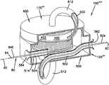
- FIG. 1is an exploded perspective view of a cable winding and unwinding device according to the principles of the present disclosure
- FIG. 2is another exploded perspective view of the cable winding and unwinding device of FIG. 1 ;
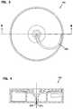
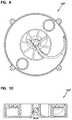
- FIG. 3is a top plan view of the cable winding and unwinding device of FIG. 1 ;
- FIG. 4is a cross-sectional side elevation view of the cable winding and unwinding device of FIG. 1 ;
- FIG. 5is a bottom plan view of the cable winding and unwinding device of FIG. 1 ;
- FIG. 6is a side elevation view of the cable winding and unwinding device of FIG. 1 ;
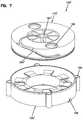
- FIG. 7is an exploded perspective view of another cable winding and unwinding device according to the principles of the present disclosure.
- FIG. 8is another exploded perspective view of the cable winding and unwinding device of FIG. 7 ;
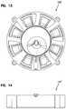
- FIG. 9is a top plan view of the cable winding and unwinding device of FIG. 7 ;
- FIG. 10is a cross-sectional side elevation view of the cable winding and unwinding device of FIG. 7 ;
- FIG. 11is a cross-sectional end elevation view of the cable winding and unwinding device of FIG. 7 ;
- FIG. 12is an opposite end elevation view of the cable winding and unwinding device of FIG. 7 ;
- FIG. 13is a bottom plan view of the cable winding and unwinding device of FIG. 7 ;
- FIG. 14is a side elevation view of the cable winding and unwinding device of FIG. 7 ;
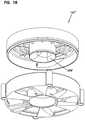
- FIG. 15is an exploded perspective view of still another cable winding and unwinding device according to the principles of the present disclosure.
- FIG. 16is another exploded perspective view of the cable winding and unwinding device of FIG. 15 ;
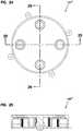
- FIG. 17is a top plan view of the cable winding and unwinding device of FIG. 15 ;
- FIG. 18is a cross-sectional end elevation view of the cable winding and unwinding device of FIG. 15 ;
- FIG. 19is a cross-sectional side elevation view of the cable winding and unwinding device of FIG. 15 ;
- FIG. 20is a bottom plan view of the cable winding and unwinding device of FIG. 15 ;
- FIG. 21is a side elevation view of the cable winding and unwinding device of FIG. 15 ;
- FIG. 22is an exploded perspective view of yet another cable winding and unwinding device according to the principles of the present disclosure.
- FIG. 23is another exploded perspective view of the cable winding and unwinding device of FIG. 22 ;
- FIG. 24is a top plan view of the cable winding and unwinding device of FIG. 22 ;
- FIG. 25is a cross-sectional side elevation view of the cable winding and unwinding device of FIG. 22 ;
- FIG. 26is a cross-sectional end elevation view of the cable winding and unwinding device of FIG. 22 ;
- FIG. 27is a bottom plan view of the cable winding and unwinding device of FIG. 22 ;
- FIG. 28is a side elevation view of the cable winding and unwinding device of FIG. 22 ;
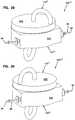
- FIG. 29is a perspective view of still another cable winding and unwinding device according to the principles of the present disclosure, the cable winding and unwinding device storing a stored portion of a telecommunications cable and paying-out a paid-out portion of the telecommunications cable;
- FIG. 30is the perspective view of FIG. 29 , but with a cable winder of the cable winding and unwinding device rotated from its position of FIG. 29 ;
- FIG. 31is the perspective view of FIG. 29 , but with a cut-away taken from the cable winder of FIG. 30 and a housing and a cable routing guide structure of the cable winding and unwinding device thereby revealing a spool of the cable winding and unwinding device with the telecommunications cable wound around the spool;
- FIG. 32is an elevation side view of the cable winding and unwinding device of FIG. 29 with the cut-away of FIG. 31 taken;
- FIG. 33is a perspective view of the telecommunications cable of FIG. 29 , the cable winder of FIG. 30 , and the spool and the cable routing guide structure of FIG. 31 assembled;
- FIG. 34is the perspective view of FIG. 33 , but with a cut-away taken from the cable winder, the spool, and the cable routing guide structure;
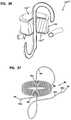
- FIG. 35is an exploded perspective view of the cable winder of FIG. 30 and the spool and the cable routing guide structure of FIG. 31 with a cut-away taken from the spool;
- FIG. 36is the perspective view of FIGS. 29 and 31 , but showing only the cable winder of FIG. 30 and the spool and the cable routing guide structure of FIG. 31 assembled and with the cut-away of FIG. 34 taken;
- FIG. 37is the perspective view of FIGS. 29, 31, and 36 , but showing only the telecommunications cable of FIG. 29 ;
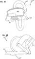
- FIG. 38is a perspective view of yet another cable winding and unwinding device according to the principles of the present disclosure.
- FIG. 39is the perspective view of FIG. 38 , but with a cut-away taken;
- FIG. 40is a perspective view of the cable winder of FIG. 30 and the spool and the cable routing guide structure of FIG. 31 assembled;
- FIG. 41is a perspective view of still another cable winding and unwinding device according to the principles of the present disclosure, the perspective view of FIG. 41 taken with a similar orientation to the perspective view of FIG. 40 ;
- FIG. 42is another perspective view of the cable winding and unwinding device of FIG. 41 ;
- FIG. 43is a top plan view of the cable winding and unwinding device of FIG. 41 .
- a cable spool assembly 100may store, pay-out, and reel-in a telecommunications cable 80 (see FIG. 37 ).
- the telecommunications cable 80extends between a first end 82 and a second end 84 .
- the first end 82 of the telecommunications cable 80may remain attached to a first device, and the second end 84 of the telecommunications cable 80 may remain attached to a second device while the cable spool assembly 100 stores, pays-out, and reels-in the telecommunications cable 80 .
- the cable spool assembly 100does not require a rotary union, but rather wraps 86 around the cable spool assembly 100 may be transformed into axial twist along a length of the telecommunications cable 80 .
- one rotation of the axial twistmay be imparted to the telecommunications cable 80 as each of the wraps 86 are wound around the cable spool assembly 100 .
- the axial twistmay be pre-applied to the telecommunications cable 80 and one rotation of the axial twist may be untwisted from the telecommunications cable 80 for each of the wraps 86 that are wrapped on the cable spool assembly 100 .
- an act of wrapping the telecommunications cable 80 about the cable spool assembly 100imparts one rotation of the axial twist about the telecommunications cable 80 for each of the wraps 86 that are wrapped upon the cable spool assembly 100 .
- the wraps 86may be transformed to the axial twist, and the axial twist may be transformed to the wraps 86 .
- the cable spool assembly 100includes a spool portion 140 that is integrated with a base 120 of the cable spool assembly 100 and a winding/unwinding member 170 that defines a cable path 200 .
- the spool portion 140includes a cable wrapping area 146 , a first flange 152 , a second flange 154 , and a circumferential outer wall 156 .
- the first flange 146extends between the wrapping area 146 and the circumferential outer wall 156 .
- the second flange 154extends radially outwardly from the cable wrapping area 146 , but is spaced an annular distance from the circumferential wall 156 and thereby forms an annular space 158 .
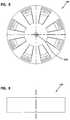
- first flange 152 and the second flange 154are each made of complimentary segments 162 and 164 , respectively, that do not overlap each other along a circumferential direction.
- an injection molding toolcan be made to injection mold the spool portion 140 in one piece.
- Spaces 166i.e., gaps
- the first flange 152may provide an entrance/exit for the telecommunications cable 80 .
- the cable winding/unwinding member 170includes a hub 172 that is positioned within the cable wrapping area 146 of the spool portion 140 .
- the winding/unwinding member 170includes a flange 174 that extends radially outwardly from the hub 172 to a circumferential flange 176 that is positioned through the annular space 158 of the spool portion 140 .
- the winding/unwinding member 170defines the cable path 200 that extends from a first end 202 to a second end 204 .
- the second end 204is oriented at least partially tangential to the cable wrapping area 146 of the spool portion 140 .
- the first end 202is positioned in the annular space 158 defined between the flange 154 and the circumferential outer wall 156 of the spool portion 140 .
- the cable path 200extends from the second end 204 along an externally facing channel 178 that extends along the circumferential flange 176 of the winding/unwinding member 170 and then onto the flange 174 of the cable winding/unwinding member 170 where it spirals toward the hub 172 of the cable winding/unwinding member 170 .
- the cable path 200is positioned generally tangentially as it approaches an axis A 1 of the cable winding/unwinding member 170 and is positioned within the cable wrapping area 146 of the spool portion 140 .
- the spool portion 140defines an axis A 2 that is concentric with the cable wrapping area 146 .
- the cable wrapping/unwrapping member 170defines an axis A 3 that is concentric with the outer flange 176 of the wrapping/unwrapping member 170 .
- the first end 202 of the cable path 200exits the cable spool assembly 100 along a direction substantially parallel to the axes A 1 , A 3 .
- the telecommunications cable 80can be deployed from and retracted into an opening 206 (see FIGS. 4 and 5 ) that is positioned at the first end 202 of the cable path 200 .
- the opening 206is defined on the winding/unwinding member 170 .
- the winding/unwinding member 170may be rotated relative to the base 120 by engaging a drive attachment 194 (e.g., a hex head) of the hub 172 .
- a drive attachment 194e.g., a hex head
- the winding/unwinding member 170may be rotated relative to the base 120 by engaging a drive attachment 194 (e.g., a hex head) of the hub 172 .
- a drive attachment 194e.g., a hex head
- a portion of the telecommunications cable 80 that is wrapped about the cable wrapping area 146may be drawn into the cable path 200 starting at the second end 204 and ending at the first end 202 .
- the deployment of the telecommunications cable 80may rotate the winding/unwinding member 170 relative to the base 120 as tension in the telecommunications cable 80 may urge the rotation of the winding/unwinding member 170 .
- the first end 82 of the telecommunications cable 80may be deployed through the opening 206 .
- a length of the telecommunications cable 80may extend between the cable spool assembly 100 and the second end 84 and may exit the cable spool assembly 100 through the spaces 166 of the base 120 .
- the second end 84is substantially positioned at a fixed distance relative to the cable spool assembly 100 and is therefore non-deployable.
- FIGS. 7-14another embodiment of a cable spool assembly 100 ′ is illustrated.
- the cable spool assembly 100 ′is similar to the cable spool assembly 100 and, in general, the description of the cable spool assembly 100 ′ will focus on certain additional features provided on the cable spool assembly 100 ′.
- the cable spool assembly 100 ′includes a base 120 ′ and a winding/unwinding member 170 ′.
- the winding/unwinding member 170 ′defines a cable path 200 ′ similar to the cable path 200 .
- the cable path 200 ′includes an opening 206 ′ with a smooth transitional area 208 that allows the telecommunications cable 80 to enter and exit the cable path 200 ′ in a range of directions.
- the transitional area 208includes curved surfaces that prevent the telecommunications cable 80 from bending in excess of any bend radius limitations. Such bend radius limitations are typically found on optical fiber cables.
- the transitional area 208may further benefit the cable spool assembly 100 ′ by reducing friction as the telecommunications cable 80 enters and exits the cable spool assembly 100 ′.
- the winding/unwinding member 170 ′may further include a drive attachment 194 ′ that includes a square internal drive. As illustrated at FIG. 7 , the winding/unwinding member 170 ′ may further include finger pockets 196 that may be engaged by placing a finger or a thumb in and thereby rotating the winding/unwinding member 170 ′ relative to the base 120 ′.
- the base 120 ′may include a set of fastener holes 168 .
- the fastener holes 168may be used to mount the cable spool assembly 100 ′ to a structure (a panel, a cabinet, etc.).
- the base 120 ′may further include an entrance/exit 148 . As illustrated, the entrance/exit 148 extends radially outwardly from a spool portion 140 ′ and provides a conduit between an interior of the spool portion 140 ′ and an exterior of the cable spool assembly 100 ′.
- the smooth transitional area 208 and the entrance/exit 148may work together to allow the telecommunications cable 80 to enter and exit the cable spool assembly 100 ′ along a plane that is substantially parallel to a mounting plane of the cable spool assembly 100 ′.
- the retraction and deployment of the telecommunications cable 80 from the cable spool assembly 100 ′is similar to that of the cable spool assembly 100 .
- the first end 82 of the telecommunications cable 80may either be routed downwardly through the opening 206 ′ and exit through a bottom of the cable spool assembly 100 ′, or the first end 82 may be routed through the entrance/exit 148 and thereby enter and exit the cable spool assembly 100 ′ substantially perpendicular to an axis of rotation of the winding/unwinding member 170 ′ (e.g., the axis A 3 ).
- the second end 84may enter/exit the cable spool assembly 100 ′ in a manner similar to the cable spool assembly 100 .
- the first end 82may be extended away from or retracted into the cable spool assembly 100 ′ in any direction within a hemisphere H, as illustrated at FIG. 11 .
- an entrance/exit vector Vmay vary in orientation as the first end 82 is extended from and retracted into the cable spool assembly 100 ′.
- FIGS. 15-21a third embodiment of a cable spool assembly 100 ′′ is illustrated.
- the cable spool assembly 100 ′′is similar to the cable spool assembly 100 ′ but may include smaller proportions on an entrance/exit guiding funnel 208 ′ compared with the smooth transitional area 208 .
- the cable spool assembly 100 ′′′includes several of the features found in the cable spool assemblies 100 , 100 ′, and 100 ′′, and wraps and unwraps the telecommunications cable 80 in a similar manner when deploying and retracting the telecommunications cable 80 .
- the cable spool assembly 100 ′′′further includes a spring 350 that is rotationally connected between a winding/unwinding member 170 ′′ and a base 120 ′′.
- a cable path 200 ′′is substantially included in an interior of the winding/unwinding member 170 ′′ and is illustrated not including an externally facing channel.
- the spring 350may torsionally preload the winding/unwinding member 170 ′′ against the base 120 ′′ and thereby provide automatic retraction or semi-automatic retraction of the telecommunications cable 80 into the cable spool assembly 100 ′′′.
- the winding/unwinding member 170 ′′may be held with respect to the base 120 ′′ and thereby prevent unwanted retraction of the telecommunications cable 80 even though the spring 350 is applying a torsional load between the winding/unwinding member 170 ′′ and the base 120 ′′.
- the winding/unwinding member 170 ′′includes a hub 172 ′ that includes a catch and release mechanism 173 (see FIG. 23 ).
- the catch and release mechanism 173may include dogs, one-way clutches, centrifugal weights, and/or other items that are typically found in spool hubs that have catch and release features.
- the catch and release mechanism 173may be adapted to hold the winding/unwinding member 170 ′′ rotationally with respect to the base 120 ′′ at certain rotational positions. Alternatively, the catch and release mechanism 173 may be adapted to hold the winding/unwinding member 170 ′′ at certain rotational velocities and release the winding/unwinding member 170 ′′ at other rotational velocities and thereby allow a user to trigger the activation of the spring 350 and the rewinding of the telecommunications cable 80 .
- tension in the telecommunications cable 80may result in winding the spring 350 .
- the winding of the spring 350may be released upon the retraction of the telecommunications cable 80 .
- the cable spool assembly 100 ′′′′wraps and unwraps the telecommunications cable 80 similar to the cable spool assemblies 100 , 100 ′, 100 ′′, 100 ′′′.
- the cable spool assembly 100 ′′′′includes a base 120 ′′′ that has similarities to bases 120 , 120 ′, 120 ′′.
- the cable spool assembly 100 ′′′′also includes a winding/unwinding member 170 ′′′ similar to the winding/unwinding members 170 , 170 ′, 170 ′′.
- the cable spool assembly 100 ′′′′may include a spool 400 that is rotationally separate from the winding/unwinding member 170 ′′′ and the base 120 ′′′.
- the spool 400may be connected to the base 120 ′′′.
- the cable spool assembly 100 ′′′′may retract and deploy the telecommunications cable 80 by rotationally moving the winding/unwinding member 170 ′′′ relative to the base 120 ′′′.
- the winding/unwinding member 170 ′′′may be spring loaded relative to the base 120 ′′′.
- the first end 82may be pulled away from the cable spool assembly 100 ′′′′ and thereby cause rotation of the winding/unwinding member 170 ′′′.
- the telecommunications cable 80may be deployed by pulling on the second end 84 thereby rotating the spool 400 .
- deploying the telecommunications cable 80 by the first end 82may be preferred as any twisting that may occur along the telecommunications cable 80 is distributed along a length of the telecommunications cable 80 .
- the telecommunications cable 80may extend from the cable spool assembly 100 ′′′′ along an axis A 5 that includes an external portion 82 e of the telecommunications cable 80 adjacent the first end 82 and an external portion 84 e of the telecommunications cable 80 that is adjacent the second end 84 .
- the telecommunications cable 80may be deployed and retracted along the axis A 5 , and portions of the telecommunications cable 80 on both sides of the cable spool assembly 100 ′′′′ may be coaxial with each other.
- the base 120 ′′′may include a housing 500 that generally encloses the telecommunications cable 80 when the telecommunications cable 80 is within the cable spool assembly 100 ′′′′.
- the housing 500may include a funnel 582 adjacent the external portion 82 e, and a funnel 584 adjacent the external portion 84 e.
- the funnels 582 , 584allow the external portion 82 e and the external portion 84 e to be pulled in directions other than along the axis A 5 without violating bend radius requirements of the telecommunications cable 80 .
- the base 120 ′′′includes a first passage 502 that is adjacent the external portion 82 e.
- the base 120 ′′′may also include a passage 504 adjacent the external portion 84 e.
- the passage 504aligns the external portion 84 e generally tangential to the spool 400 .
- the first passage 502may align the external portion 82 e with the external portion 84 e.
- the first passage 502may further align the telecommunications cable 80 with the winding/unwinding member 170 ′′′.
- the telecommunications cable 80is thereby aligned generally coaxially with an axis A 6 of the cable spool assembly 100 ′′′ when transitioning between the first passage 502 and the winding/unwinding member 170 ′′′.
- the first passage 502may be defined within a tube-like structure 512
- the passage 504may be defined within a tube-like structure 514 .
- the first passage 502may align with the funnel 582 at a first end.
- the first passage 502may become concentric with the axis A 6 at a second end.
- the spool 400may be rotatably mounted on the second end of the structure 512 .
- the winding/unwinding member 170 ′′′may be rotatably mounted at the second end of the structure 512 .
- the tube-like structure 514may be aligned with the funnel 584 and may be further aligned with the first end of the first passage 502 .
- the winding/unwinding member 170 ′′′may include a housing 600 .
- the housing 600in conjunction with the housing 500 , may substantially enclose the telecommunications cable 80 in the cable spool assembly 100 ′′′′.
- the housing 600may rotate along with the winding/unwinding member 170 ′′′.
- the housing 600may be sealed with the housing 500 and thereby provide a sealed enclosure with the housing 500 to house the telecommunications cable 80 .
- the winding/unwinding member 170 ′′′may include a passage 602 that extends from a first end 602 a (see FIG. 34 ) to a second end 602 b (see FIG. 33 ).
- the first end 602 amay be generally tangentially aligned with the spool 400 .
- the first end 602 amay be generally aligned with a wrapping area 402 of the spool 400 .
- the wrapping area 402may extend between a first flange 404 and a second flange 406 of the spool 400 .
- the passage 602may be included in a tube-like structure 612 .
- the tube-like structure 612may smoothly continue from the tube-like structure 512 at a joint between the tube-like structure 512 and the tube-like structure 612 .
- the tube-like structures 512 , 514 , and 612may be coated internally with a low friction material (e.g., Teflon®) to facilitate easy passage of the telecommunications cable 80 through the passages 502 , 504 , and 602 .
- a low friction materiale.g., Teflon®
- the telecommunications cable 80may be defined along various segments. As the telecommunications cable 80 is retracted and deployed, the telecommunications cable 80 may pass from one segment to other segments.
- the external portion 82 eis defined adjacent the first end 82 and may be a deployed portion of the telecommunications cable 80 adjacent the first end 82 .
- an interior segment 82 imay be defined along the length of the first passage 502 .
- an interior segment 80 i of the telecommunications cable 80may be defined.
- the interior segment 80 imay be defined along the length of the passage 602 .
- the internal segment 84 imay transition to the external portion 84 e. And finally, the external portion 84 e terminates at the second end 84 . Either or both of the ends 82 , 84 may be terminated by a fiber optic connector.
- FIGS. 38 and 39a sixth embodiment of a cable spool assembly 100 ′′′′′ is illustrated according to the principals of the present disclosure.
- the cable spool assembly 100 ′′′′′is similar to the cable spool assembly 100 ′′′′ except that the external portion 82 e is deployed from the cable spool assembly 100 ′′′′′ generally parallel to an axis A 7 of the cable spool assembly 100 ′′′′′.
- the axis A 7is generally coaxial with an axis of rotation of the spool 400 .
- the cable spool assembly 100 ′′′′′may include a housing and other features that were illustrated on the cable spool assembly 100 ′′′′.
- the first end 82extends in a direction substantially parallel to the axis A 7
- the second end 84 of the telecommunications cable 80extends tangentially to the wrapping area 402 of the spool 400 .
- the external portion 84 eis oriented approximately perpendicular to the external portion 82 e.
- the cable spool assembly 100 ′′′′′includes a base 120 ′′′′ similar to the base 120 ′′′ but with a tubular portion 512 ′ that is centered about the axis A 7 .
- the tube-like structure 512 ′includes a passage 502 ′ that is generally concentric with the axis A 7 .
- FIGS. 41-43a seventh embodiment of a cable spool assembly 100 ′′′′′′ is illustrated according to the principles of the present disclosure.
- the cable spool assembly 100 ′′′′′′is in a similar perspective view as the cable spool assembly 100 ′′′′.
- the cable spool assemblies 100 ′′′′ and 100 ′′′′′′generally perform in the same manner.
- the cable spool assembly 100 ′′′′′′includes a tube-like portion 514 ′ that is rotatably mounted about the tube-like structure 512 adjacent the spool 400 .
- FIGS. 41a seventh embodiment of a cable spool assembly 100 ′′′′′′ is illustrated according to the principles of the present disclosure.
- the cable spool assembly 100 ′′′′′′is in a similar perspective view as the cable spool assembly 100 ′′′′.
- the cable spool assemblies 100 ′′′′ and 100 ′′′′′′generally perform in the same manner.
- the cable spool assembly 100 ′′′′′′includes a tube-like portion 514 ′ that
- the rotatable mounting of the tube-like structure 514 ′allows an angle ⁇ to be defined between the tube-like structure 512 and the tube-like structure 514 ′.
- the angle ⁇ between the external portion 84 e and the external portion 82 ecan be adjusted between 0 degrees and 360 degrees.
- the angle ⁇may be a fixed angle (e.g., 90 degrees, 180 degrees, 270 degrees, etc.) and may not necessarily be adjustable.
- the angle ⁇may be adjusted as desired, including while the telecommunications cable 80 is being deployed (i.e., paid-out) and/or reeled-in.
- the paid-out end 82can be pulled from the cable spool assemblies 100 , 100 ′, 100 ′′, 100 ′′′, 100 ′′′′, 100 ′′′′′, 100 ′′′′′′ at various lengths including the extended lengths to bring the paid-out end 82 of the telecommunications cable 80 to a desired location.
- the cable spool assemblies 100 , 100 ′, 100 ′′, 100 ′′′, 100 ′′′′, 100 ′′′′′, 100 ′′′′′′do not require a rotary union. Rather, the wraps 86 of a stored portion of the telecommunications cable 80 within a storage area of the cable spool assembly 100 , 100 ′, 100 ′′, 100 ′′′, 100 ′′′′, 100 ′′′′′, 100 ′′′′′′ are transformed into axial twist along the length of the telecommunications cable 80 while the cable spool assembly 100 , 100 ′, 100 ′′, 100 ′′′, 100 ′′′′, 100 ′′′′′, 100 ′′′′′′ is paying-out a paid-out portion of the telecommunications cable 80 .
- the telecommunications cable 80is transferred from the stored portion to a transitional portion (e.g., the segments 80 i and/or 82 i ) and then to the paid-out portion 82 e.
- the transitional portion 80 i, 82 iis adjacent and between the wraps 86 of the stored portion and the paid-out portion 82 e .
- the paid-out end 82is continuously connected to the base end 84 while the telecommunications cable 80 is being paid-out.
- the cable spool assemblies 100 , 100 ′, 100 ′′, 100 ′′′, 100 ′′′′, 100 ′′′′′, 100 ′′′′′′may include a terminal.
- the terminalmay not necessarily be substantially extendable from the cable spool assembly 100 , 100 ′, 100 ′′, 100 ′′′, 100 ′′′′, 100 ′′′′′, 100 ′′′′′′.
- the terminalmay be generally stationary with the cable spool assembly 100 , 100 ′, 100 ′′, 100 ′′′, 100 ′′′′, 100 ′′′′′, 100 ′′′′′′.
- the terminalmay be fixed with the base 120 , 120 ′, 120 ′′, 120 ′′′, 120 ′′′′ of the cable spool assembly 100 , 100 ′, 100 ′′, 100 ′′′, 100 ′′′′, 100 ′′′′′, 100 ′′′′′′.
- the terminalmay be attached to the base 120 , 120 ′, 120 ′′, 120 ′′′, 120 ′′′′ by a terminal portion (i.e., the segments 84 i and/or 84 e ) of the telecommunications cable 80 .
- the terminalcan be connectorized by a fiber optic connector and/or a fiber optic adaptor.
- the terminalcan be permanently or semi-permanently connected to a fiber optic component, a fiber optic network, etc. If it is desired to change the position of the first end 82 , the terminal can remain connected to the fiber optic component, the fiber optic network, etc.
- the wraps 86can be unwrapped and transfered to the paid-out portion 82 e of the telecommunications cable 80 .
- a number of the wraps 86changes as the telecommunications cable 80 is paid-out.
- the telecommunications cable 80extends continuously between the first end 82 and the second end 84 .
- pulling the first end 82actuates the cable spool assembly 100 , 100 ′, 100 ′′, 100 ′′′, 100 ′′′′, 100 ′′′′′, 100 ′′′′′′.
- the base 120 , 120 ′, 120 ′′, 120 ′′′, 120 ′′′′typically remains stationary.
- Two of the cable spool assemblies 100 , 100 ′, 100 ′′, 100 ′′′, 100 ′′′′, 100 ′′′′′, 100 ′′′′′′may be combined.
- the mounting side of a first of the cable spool assemblies 100 ′′may be placed adjacent to the mounting side of a second of the cable spool assemblies 100 ′′.
- the second ends 84 of the first and the second of the cable spool assemblies 100 ′′may be merged (e.g., continuous with each other) thereby creating a cable spool assembly that can pay-out extended lengths of the telecommunications cable 80 from either of two ends.
Landscapes
- Physics & Mathematics (AREA)
- General Physics & Mathematics (AREA)
- Optics & Photonics (AREA)
- Storing, Repeated Paying-Out, And Re-Storing Of Elongated Articles (AREA)
- Light Guides In General And Applications Therefor (AREA)
Abstract
Description
Claims (10)
Priority Applications (1)
| Application Number | Priority Date | Filing Date | Title |
|---|---|---|---|
| US15/903,895US10625978B2 (en) | 2012-04-30 | 2018-02-23 | Cable storage spool with center feed |
Applications Claiming Priority (3)
| Application Number | Priority Date | Filing Date | Title |
|---|---|---|---|
| US201261640449P | 2012-04-30 | 2012-04-30 | |
| US13/872,655US9908742B2 (en) | 2012-04-30 | 2013-04-29 | Cable storage spool with center feed |
| US15/903,895US10625978B2 (en) | 2012-04-30 | 2018-02-23 | Cable storage spool with center feed |
Related Parent Applications (1)
| Application Number | Title | Priority Date | Filing Date |
|---|---|---|---|
| US13/872,655ContinuationUS9908742B2 (en) | 2012-04-30 | 2013-04-29 | Cable storage spool with center feed |
Publications (2)
| Publication Number | Publication Date |
|---|---|
| US20190062100A1 US20190062100A1 (en) | 2019-02-28 |
| US10625978B2true US10625978B2 (en) | 2020-04-21 |
Family
ID=49476458
Family Applications (2)
| Application Number | Title | Priority Date | Filing Date |
|---|---|---|---|
| US13/872,655ActiveUS9908742B2 (en) | 2012-04-30 | 2013-04-29 | Cable storage spool with center feed |
| US15/903,895Active2033-08-06US10625978B2 (en) | 2012-04-30 | 2018-02-23 | Cable storage spool with center feed |
Family Applications Before (1)
| Application Number | Title | Priority Date | Filing Date |
|---|---|---|---|
| US13/872,655ActiveUS9908742B2 (en) | 2012-04-30 | 2013-04-29 | Cable storage spool with center feed |
Country Status (4)
| Country | Link |
|---|---|
| US (2) | US9908742B2 (en) |
| EP (1) | EP2845281A4 (en) |
| CN (1) | CN104412475B (en) |
| WO (1) | WO2013165903A1 (en) |
Cited By (1)
| Publication number | Priority date | Publication date | Assignee | Title |
|---|---|---|---|---|
| US20220041401A1 (en)* | 2020-08-06 | 2022-02-10 | RIJATEK Design Pty Ltd | Cable reel |
Families Citing this family (42)
| Publication number | Priority date | Publication date | Assignee | Title |
|---|---|---|---|---|
| US8500054B2 (en)* | 2004-09-27 | 2013-08-06 | Deka Products Limited Partnership | Infusion set improvements |
| BR112014009727A2 (en)* | 2011-10-25 | 2017-04-18 | Digital Innovations Llc | system and method for protection and storage of small electronic components |
| CN104412475B (en)* | 2012-04-30 | 2019-01-15 | Adc电信公司 | Cable storage spool with center feed |
| WO2013165899A1 (en) | 2012-04-30 | 2013-11-07 | Adc Telecommunications, Inc. | Cable payout cassette with single layer cable storage area |
| US9722407B2 (en) | 2012-04-30 | 2017-08-01 | Commscope Technologies Llc | Guided cable storage assembly with switchbacks |
| US9126802B2 (en) | 2012-04-30 | 2015-09-08 | Adc Telecommunications, Inc. | Payout spool with automatic cable disconnect/reconnect |
| US10276990B2 (en) | 2013-03-13 | 2019-04-30 | Commscope Technologies Llc | Telecommunications assembly with patch cord storage |
| US9837805B2 (en) | 2014-05-09 | 2017-12-05 | Ruggedreel Inc. | System and apparatus for electrically coupling to a cable on a rotatable reel using optical communication devices |
| EP3034449A1 (en)* | 2014-12-17 | 2016-06-22 | KONE Corporation | Rope storage unit and method for installing elevator ropes |
| KR20170108953A (en)* | 2015-01-22 | 2017-09-27 | 내쇼날 오일웰 파르코 노르웨이 에이에스 | Winch drum with internal wire storage |
| FR3035653B1 (en)* | 2015-04-29 | 2017-05-12 | Conductix Wampfler France | DEVICE AND METHOD FOR THREADING AN OPTICAL FIBER ON A COIL |
| US20160354570A1 (en)* | 2015-06-08 | 2016-12-08 | Lorelyn Cajucom Arroyo | Oxygen Cord Retractor and Organizer |
| EP3326016B1 (en)* | 2015-07-23 | 2022-09-07 | Commscope Technologies LLC | Cable spool re-orientation device for a wall box |
| WO2017066842A1 (en)* | 2015-10-21 | 2017-04-27 | Micro-X Limited | Rotary keeper for cabling |
| EP3417327A1 (en) | 2016-02-15 | 2018-12-26 | CommScope Connectivity Belgium BVBA | Spool with multi-position loop keeper |
| US10101552B2 (en)* | 2016-04-18 | 2018-10-16 | Konnectronix, Inc. | Retractable fiber optic reel assembly |
| WO2017198708A1 (en)* | 2016-05-18 | 2017-11-23 | CommScope Connectivity Belgium BVBA | Cable slack storage device |
| USD840947S1 (en)* | 2016-05-27 | 2019-02-19 | Mothers Lounge, Llc | Cable storage and provisioning device |
| US10894694B2 (en)* | 2017-03-31 | 2021-01-19 | All Clear Fire Systems, Llc | Body mount and retractor for support of hands free portable power, video enhancement, and data transfer between wireless devices |
| US10703557B2 (en)* | 2017-06-07 | 2020-07-07 | Illinois Tool Works Inc. | Drums for transporting and feeding wire |
| CN111417470B (en)* | 2017-12-14 | 2023-03-07 | 里奇工具公司 | Segmented sewer cleaning cable system for clean use, storage and transport |
| CN108147229B (en)* | 2018-02-08 | 2024-05-03 | 中国大唐集团科学技术研究院有限公司华中分公司 | High-voltage test wire length regulator |
| DE202018101827U1 (en)* | 2018-04-04 | 2018-04-13 | Igus Gmbh | Modular rotary feedthrough with energy guiding chains |
| WO2019200176A1 (en)* | 2018-04-11 | 2019-10-17 | Lb Accessories Llc | Pacifier retention device |
| CN108538204B (en)* | 2018-04-23 | 2020-11-06 | 京东方科技集团股份有限公司 | Wire bunching device and display device |
| CN108549134B (en)* | 2018-04-24 | 2020-04-10 | 安徽春辉仪表线缆集团有限公司 | Optical cable steel belt longitudinal wrapping device capable of preventing steel belt from being broken |
| US20190292007A1 (en)* | 2018-06-25 | 2019-09-26 | Abdul Khan | String light storage container |
| EP3626662B1 (en)* | 2018-09-19 | 2021-09-08 | iPEK International GmbH | Cable reel |
| DE102018133484A1 (en)* | 2018-12-21 | 2020-06-25 | Wolffkran Holding Ag | Rope storage device for a crane rope |
| CN110181556B (en)* | 2019-05-09 | 2021-01-15 | 浙江树人学院(浙江树人大学) | Peripheral pipeline installation rotating base for industrial robot |
| KR102819127B1 (en)* | 2020-03-31 | 2025-06-12 | 주식회사 엘지에너지솔루션 | High Voltage Busbar Having Dissimilar Metals and Manufacturing Method Thereof |
| US11240925B1 (en)* | 2020-10-20 | 2022-02-01 | Dell Products L.P. | System and method for long cable management and plug protection system |
| US11619794B2 (en) | 2021-04-20 | 2023-04-04 | Palo Alto Research Center Incorporated | System for installing optical fiber |
| US11460658B1 (en) | 2021-04-20 | 2022-10-04 | Palo Alto Research Center Incorporated | Retractable reel for handling optical fiber |
| US11668889B2 (en) | 2021-04-20 | 2023-06-06 | Palo Alto Research Center Incorporated | System for applying pre-strain to an optical sensor |
| US11543611B2 (en) | 2021-04-20 | 2023-01-03 | Palo Alto Research Center Incorporated | Smart cassette for installing optical fiber |
| US12306443B2 (en) | 2021-08-23 | 2025-05-20 | Xerox Corporation | Optical fiber attachment device |
| US12312207B2 (en)* | 2021-09-24 | 2025-05-27 | Javier Ruiz Poo | Apparatus for winding cables |
| CN113816227B (en)* | 2021-10-11 | 2023-08-11 | 武汉锐科光纤激光技术股份有限公司 | Cable turnover disc |
| CN115258813B (en)* | 2022-08-17 | 2024-11-22 | 池州市谦跃信息技术有限公司 | An adaptive straightening component for optical cable |
| WO2024092142A1 (en)* | 2022-10-28 | 2024-05-02 | Commscope Technologies Llc | Telecommunication enclosure with spool |
| CN115783881B (en)* | 2022-11-18 | 2025-06-27 | 广东广深电缆有限公司 | Cable processing equipment and cable processing method |
Citations (231)
| Publication number | Priority date | Publication date | Assignee | Title |
|---|---|---|---|---|
| US342354A (en) | 1886-05-25 | Ticket-case | ||
| US415423A (en) | 1889-11-19 | Ribbon-holder | ||
| US1137133A (en) | 1914-11-02 | 1915-04-27 | Joseph W Horner | Twine-holder. |
| US1276825A (en) | 1916-07-21 | 1918-08-27 | David Swope | Automatic take-up attachment for portable-telephone conductors. |
| US1588577A (en) | 1925-06-22 | 1926-06-15 | Heifler Isidore | Container and dispensing device for tape-like bodies |
| US1592030A (en) | 1925-06-04 | 1926-07-13 | Dietzgen Co Eugene | Tape reel |
| US1858371A (en) | 1931-09-30 | 1932-05-17 | William S Lutz | Gold leaf laying device |
| US1914654A (en)* | 1931-10-17 | 1933-06-20 | Appleton Electric Co | Multiple hose reel |
| US2206352A (en) | 1939-01-20 | 1940-07-02 | Jay T Hellmann | Cord take-up |
| US2227442A (en) | 1939-01-24 | 1941-01-07 | Elastic Knitted Wire Co Inc | Apparatus for coiling helical wire |
| US2260109A (en) | 1940-02-19 | 1941-10-21 | Amdal Hans | Apparatus for operating lifesaving buoys |
| US2440974A (en) | 1945-08-24 | 1948-05-04 | Stewart H Resch | Combined humidifier and toilet paper dispenser |
| US2605060A (en) | 1949-09-29 | 1952-07-29 | Northwestern Steel & Wire Co | Wire magazine and feed mechanism |
| US2752106A (en) | 1952-09-02 | 1956-06-26 | Reuben A Thompson | Gauze holder |
| US2776093A (en) | 1953-07-20 | 1957-01-01 | James H Cox | Hose retriever |
| US2874918A (en) | 1954-07-24 | 1959-02-24 | Steiber Sven Ingemar | Wire reeling mechanism |
| US2905409A (en) | 1955-02-02 | 1959-09-22 | Rea Magnet Wire Company Inc | Wire dispensing device |
| US2941746A (en) | 1957-12-16 | 1960-06-21 | Joseph D Dawkins | Machine for reeling electric cable |
| US3015384A (en) | 1958-12-09 | 1962-01-02 | Clemson Bros Inc | Container and dispenser for coiled strip stock, bandsaw blade stock, and the like |
| US3120355A (en) | 1962-01-25 | 1964-02-04 | I T E Circuit Breaker Corp | Transfer mechanism |
| US3160360A (en) | 1963-10-10 | 1964-12-08 | Willy Buehler A G | Line-storing assembly for towing apparatus or the like |
| US3186659A (en)* | 1963-05-27 | 1965-06-01 | Carter H Arnold | Device for coiling and storing wire rope and the like |
| US3208121A (en) | 1963-10-03 | 1965-09-28 | James C Price | Storage reel |
| US3312381A (en)* | 1963-04-25 | 1967-04-04 | Zinser Textilmaschinen Gmbh | Storing device for transported flexible elements |
| US3322372A (en)* | 1965-04-12 | 1967-05-30 | Electrolux Ab | Cable winding device |
| DE1253985B (en) | 1965-01-29 | 1967-11-09 | Electrolux Ab | Cable winding device |
| US3632061A (en) | 1968-05-23 | 1972-01-04 | Philips Corp | Wire-unwinding device |
| US3640440A (en) | 1969-04-25 | 1972-02-08 | Elitex Z Textilriho Strojirens | Pneumatic circuit for controlling the feeding of yarn into a yarn magazine |
| US3703261A (en) | 1971-04-07 | 1972-11-21 | Southwire Co | Orbital coiler |
| US3737112A (en) | 1971-04-23 | 1973-06-05 | Wesco Industries Corp | Yarn feeding and storage device for textile producing machine |
| US3759455A (en) | 1972-09-28 | 1973-09-18 | Wesco Industries Corp | Filament feeding and storage device |
| US3822834A (en) | 1972-06-05 | 1974-07-09 | Fathom Oceanology Ltd | Cable transfer apparatus |
| US3831879A (en) | 1970-03-11 | 1974-08-27 | Us Navy | Wire dispenser |
| US3843071A (en) | 1973-01-02 | 1974-10-22 | T Graham | Strip material container and dispenser |
| US3844504A (en) | 1972-04-05 | 1974-10-29 | Lawson Hemphill | Method and apparatus for handling yarn |
| US4008791A (en) | 1975-09-08 | 1977-02-22 | Cascade Corporation | Takeup reel for combined hose and cable |
| US4055314A (en) | 1976-09-17 | 1977-10-25 | Wyrepak Industries, Inc. | Wire pay-off cap assembly for wire spools |
| US4108390A (en) | 1977-02-15 | 1978-08-22 | The United States Of America As Represented By The Secretary Of The Army | Paper tape canister |
| US4111380A (en) | 1977-06-14 | 1978-09-05 | Heuckroth Carl C | Welding wire spool shroud |
| US4174816A (en) | 1973-06-06 | 1979-11-20 | The Regents Of The University Of Minnesota | Sterile surgical cord and tube retractor |
| US4186897A (en) | 1978-07-31 | 1980-02-05 | Brown Maurice H | Wire control mechanism |
| US4222535A (en) | 1979-07-16 | 1980-09-16 | Mossberg Hubbard, Division Of Wanskuck Company | Wire dereeling apparatus |
| US4273392A (en) | 1979-05-04 | 1981-06-16 | Stinson Constance E | Tissue roll holder |
| US4282954A (en) | 1980-02-11 | 1981-08-11 | Hill John O | Rewinder device |
| US4301611A (en) | 1978-06-23 | 1981-11-24 | Catuma Pty, Limited | Fishing line caster |
| US4383655A (en) | 1980-04-16 | 1983-05-17 | Lucke Apparate-Bau Gmbh | Yarn storage device |
| US4436224A (en) | 1982-02-22 | 1984-03-13 | Mcinerny John | Dispenser for fluids and paper towels |
| US4441531A (en) | 1980-07-21 | 1984-04-10 | Nissan Motor Co., Ltd. | Weft detaining device of shuttleless loom |
| US4535946A (en) | 1983-06-03 | 1985-08-20 | Henri Thevenon | Fixed position machine for coiling down a cable |
| US4565333A (en) | 1984-07-11 | 1986-01-21 | Fleet Industries | Cable winder system |
| US4664260A (en) | 1986-04-14 | 1987-05-12 | Seneca Wire And Manufacturing Company | Container/pallet for annular packages of strand material |
| US4773607A (en) | 1986-03-28 | 1988-09-27 | Sat (Societe Anonyme De Telecommunications) | Apparatus for accumulating a filiform element such as an optical fiber, at different speeds |
| EP0292460A2 (en) | 1987-05-21 | 1988-11-23 | Gh Produkt Ab | Electric cable reel |
| US4880182A (en) | 1988-03-25 | 1989-11-14 | Stanley Gelfman | Cable reel |
| US4936452A (en) | 1989-06-05 | 1990-06-26 | Pauley Helena R | Bathroom tissue container |
| FR2645360A1 (en) | 1989-03-31 | 1990-10-05 | Ifremer | Method and device for connecting in situ a transmission cable to a carrier cable |
| JPH02296201A (en) | 1989-05-11 | 1990-12-06 | Topcon Corp | Cassette type optical fiber cable for surgical operation |
| US4978191A (en) | 1989-02-14 | 1990-12-18 | The Furukawa Electric Co., Ltd. | Connector device |
| US5018678A (en) | 1989-10-30 | 1991-05-28 | Hughes Aircraft Company | Fiber payout machine |
| US5022600A (en) | 1988-05-16 | 1991-06-11 | Commissariat A L'energie Atomique | Winder-unwinder for optical fibre cables |
| US5058259A (en) | 1988-03-25 | 1991-10-22 | Nippon Steel Welding Products & Engineering Co., Ltd. | Method and apparatus for passing threadlike pieces through tubular products |
| US5069523A (en) | 1988-12-08 | 1991-12-03 | Siemens Aktiengesellschaft | Cassette for spare lengths of light waveguides to be used at the site to be spliced |
| US5078466A (en) | 1991-04-19 | 1992-01-07 | Allied-Signal Inc. | Fiber optic rotary joint |
| US5098028A (en) | 1989-06-05 | 1992-03-24 | Alps Electric Co., Ltd. | Clock spring connector including cable stowage grooves |
| US5117859A (en) | 1990-11-19 | 1992-06-02 | Elden Barbieri | Flexible hose retractor |
| US5165543A (en) | 1991-09-25 | 1992-11-24 | At&T Bell Laboratories | Protected optical fiber package |
| EP0531628A1 (en) | 1991-06-15 | 1993-03-17 | Walter Rose GmbH & Co. KG | Device for dividing optical fibre cables and wires |
| US5230480A (en)* | 1990-05-16 | 1993-07-27 | Perry Calvin W | Flexible member reeling device |
| JPH05303018A (en) | 1991-09-09 | 1993-11-16 | Sumitomo Electric Ind Ltd | Surplus length processing mechanism for optical fiber in optical cable terminal |
| US5265822A (en) | 1992-07-13 | 1993-11-30 | Shober Jr Robert C | IV tube support assembly |
| US5268986A (en) | 1991-09-09 | 1993-12-07 | Sumitomo Electric Industries, Ltd. | Redundant length treatment mechanism for optical fiber at terminal of optical cable |
| US5277314A (en) | 1991-06-18 | 1994-01-11 | The Lincoln Electric Company | Retainer ring for welding wire container disclosure |
| US5294068A (en) | 1991-09-26 | 1994-03-15 | Sensormatic Electronics Corporation | Dispenser for different width label rolls and method of using |
| US5305937A (en) | 1992-08-12 | 1994-04-26 | Barnett Sharon R | Dispenser for supplies |
| US5332171A (en) | 1991-03-15 | 1994-07-26 | Josef Steff | Winding device for winding up and unwinding a tube, cable or hose |
| US5335874A (en) | 1992-11-20 | 1994-08-09 | Siecor Corporation | Connectorized optical fiber cable reel |
| GB2275041A (en) | 1993-02-05 | 1994-08-17 | Benthos Inc | Cable,hose or rope supply:coiling and uncoiling |
| US5367827A (en) | 1992-11-05 | 1994-11-29 | Koito Manufacturing Co., Ltd. | Wire guide structure for power window |
| US5374005A (en) | 1987-06-22 | 1994-12-20 | British Telecommunications Public Limited Company | Fibre coiling |
| US5388781A (en) | 1991-01-30 | 1995-02-14 | Sauber; Charles J. | Cable pulling and reeling apparatus having anti-spill device and method |
| US5421530A (en) | 1993-11-23 | 1995-06-06 | Hughes-Avicom International, Inc. | Cord retractor mechanism |
| US5450509A (en) | 1994-07-26 | 1995-09-12 | Alliedsignal Inc. | Fiber optic rotary joint |
| US5465917A (en)* | 1994-05-23 | 1995-11-14 | Kosch; Delmar D. | Welding wire dispenser with adjustable brake |
| US5481607A (en) | 1994-09-30 | 1996-01-02 | Hsiao; Tien J. | Automatic rewinding device for the conductor of a telephone transmitter |
| US5494446A (en) | 1994-01-05 | 1996-02-27 | Delucia; Eugene | Receptacle mounted, retractable, extension cord |
| US5544836A (en) | 1994-06-03 | 1996-08-13 | Lloyds International Trust | Extensible and self-retractable cable device |
| US5598987A (en) | 1995-09-20 | 1997-02-04 | Wachowicz; Walter J. | Dispenser for rolled paper products |
| US5607316A (en) | 1995-01-05 | 1997-03-04 | Yazaki Corporation | Structure for fixing a flat cable to a cylindrical rotator |
| US5630456A (en) | 1996-05-08 | 1997-05-20 | Hugo; Marie J. R. | Window blind cord winding apparatus |
| US5641067A (en) | 1995-08-30 | 1997-06-24 | Ellis; David A. | Retractable speaker wire |
| FR2743359A1 (en) | 1996-01-08 | 1997-07-11 | Nereides | Winder electric cable or hose carrying current or fluid |
| US5669571A (en) | 1995-12-04 | 1997-09-23 | Graybill; Larry Dean | Electrical cord storage and dispensing organizer |
| US5679015A (en) | 1994-10-15 | 1997-10-21 | Alcatel Kabel Ag & Co. | Device for the transmission of signals between two terminals |
| US5689605A (en) | 1995-02-09 | 1997-11-18 | Lucent Technologies Inc. | Splice holder assembly for an optical fiber cable splice closure |
| US5758834A (en) | 1996-08-20 | 1998-06-02 | Illinois Tool Works Inc. | Welding wire storage and shipping container |
| US5772146A (en) | 1993-12-22 | 1998-06-30 | Nihon Plast Co., Ltd. | Reel device for cable |
| US5797558A (en) | 1996-02-12 | 1998-08-25 | Preco New Products Corp. | Uni-directional cord take-up device |
| US5802237A (en) | 1997-04-18 | 1998-09-01 | Minnesota Mining And Manufacturing Company | Optical fiber organizer |
| US5857285A (en) | 1997-01-22 | 1999-01-12 | Little; Joe | Storage device for hooks and leaders |
| US5887815A (en)* | 1997-11-03 | 1999-03-30 | Pierce; Steve | Cable winding device for electrically powered mining vehicles |
| US5915062A (en) | 1997-07-01 | 1999-06-22 | Lucent Technologies Inc. | Low loss optical fiber reel |
| US5913487A (en) | 1998-04-17 | 1999-06-22 | Leatherman; Michael | Retractable cable system |
| US5915641A (en) | 1993-04-19 | 1999-06-29 | Reel-A-Pail, Inc. | Reel inside bucket |
| US5921497A (en) | 1997-12-19 | 1999-07-13 | Lucent Technologies Inc. | Cable rotary joint |
| USD412439S (en) | 1997-06-27 | 1999-08-03 | Johnson & Johnson Limited | Container for impregnated wipes |
| WO1999041183A1 (en) | 1998-02-17 | 1999-08-19 | Gibbs James Matthews Irvine | Cable storage device |
| US5993229A (en) | 1996-09-13 | 1999-11-30 | Yazaki Corporation | Relaying apparatus between relative rotary members |
| US5996930A (en)* | 1996-03-13 | 1999-12-07 | Sumitomo Electric Industries, Ltd. | Line dispenser and dispensing method |
| US6015110A (en) | 1996-12-17 | 2000-01-18 | Lai; Cheng-Ting | Wire receiving device |
| US6019308A (en) | 1998-09-28 | 2000-02-01 | Huang; Harrison | Device for dispensing plastic film roll |
| USD422170S (en) | 1999-07-08 | 2000-04-04 | Harris Jr Bennie | Paper towel dispenser |
| US6077108A (en) | 1997-12-31 | 2000-06-20 | Krone Gmbh | Patch panel with retractable patch cord |
| JP2000284129A (en) | 1999-04-01 | 2000-10-13 | Furukawa Electric Co Ltd:The | Optical fiber cord storage device |
| US6141948A (en) | 1997-04-04 | 2000-11-07 | Lefebvre Freres Ltd | Apparatus for making twisted wire |
| JP2001091753A (en) | 1999-09-13 | 2001-04-06 | Lucent Technol Inc | Optical fiber cassette |
| US6215938B1 (en) | 1998-09-21 | 2001-04-10 | Adc Telecommunications, Inc. | Fiber optic cabinet and tray |
| US6220413B1 (en) | 1999-10-19 | 2001-04-24 | Siecor Operations, Llc | Retractable cable reel |
| JP2001169452A (en) | 1999-12-02 | 2001-06-22 | Yazaki Corp | Wire harness winding device |
| US6250578B1 (en) | 1999-05-20 | 2001-06-26 | Lucent Technologies Inc. | Cable winding housing |
| US6260781B1 (en) | 1998-12-16 | 2001-07-17 | Lincoln Global, Inc. | Method and apparatus for packing wire in a storage drum |
| US6276625B1 (en) | 1999-08-03 | 2001-08-21 | Winston C. Chee | Tether storage system |
| US6305958B1 (en) | 1998-07-23 | 2001-10-23 | Sumitomo Wiring Systems, Ltd. | Cable reel and assembling method thereof |
| US6311007B1 (en) | 1999-09-07 | 2001-10-30 | Lucent Technologies Inc. | Fiber-optic cable tray having adjustable components |
| US6325665B1 (en) | 2000-04-25 | 2001-12-04 | Yu-Lin Chung | Power adapter with cable storage device |
| JP2001339837A (en) | 2000-05-25 | 2001-12-07 | Yazaki Corp | Assembly method and assembly jig for wire harness winding device |
| US6328243B1 (en) | 1999-06-18 | 2001-12-11 | Yazaki Corporation | Reel device for wire harness |
| US6349893B1 (en) | 2000-02-01 | 2002-02-26 | Avaya Technology Corp. | Retractable fiber slack storage device |
| US6361237B1 (en) | 1999-11-19 | 2002-03-26 | Raytheon Company | Coupling device |
| US6375109B1 (en) | 2000-02-29 | 2002-04-23 | Sheng-Hsin Liao | Wire winding box for short distance use |
| US6405961B1 (en) | 2000-07-05 | 2002-06-18 | At&T Corp | Storage assembly |
| US6422503B1 (en) | 2001-05-29 | 2002-07-23 | Michele Renee Hoo Kong | Toilet paper roll dispenser |
| US6434313B1 (en) | 2000-10-31 | 2002-08-13 | Corning Cable Systems Llc | Fiber optic closure with couplers and splice tray |
| US6433274B1 (en) | 2000-01-06 | 2002-08-13 | Mobility Electronic, Inc. | Power converter device |
| US20020122643A1 (en) | 2000-07-11 | 2002-09-05 | Bueschelberger Hanns J | Fiber optic coil for a fiber optic measuring system and method for producing the same |
| US6484958B1 (en) | 2001-11-20 | 2002-11-26 | Dowslake Microsystems Corporation | Patch cord caddy |
| US6501898B1 (en) | 1999-05-27 | 2002-12-31 | Telefonaktiebolaget Lm Ericsson (Publ) | Handling of optical fibres in confined or limited spaces |
| JP2003029059A (en) | 2001-07-11 | 2003-01-29 | Mitsubishi Cable Ind Ltd | Optical module |
| US6522826B2 (en)* | 2001-05-11 | 2003-02-18 | Fibersense Technology Corporation | System and method of winding a fog coil |
| US20030059192A1 (en) | 2001-09-21 | 2003-03-27 | Johnson Christopher P. | Apparatus and method for holding coilable elongated product |
| US20030089818A1 (en) | 1999-12-21 | 2003-05-15 | Anne-Cecile Reau | A reel for paying out elongate elements for interior cabling of buildings |
| US20030095773A1 (en) | 2001-11-20 | 2003-05-22 | Toyokuni Electric Cable Co., Ltd. | Device for winding optical fiber cable |
| US6572393B2 (en) | 2001-02-15 | 2003-06-03 | Sumitomo Wiring Systems, Ltd. | Cable reel |
| US6574922B2 (en) | 2000-10-06 | 2003-06-10 | Meritor Light Vehicle Systems | Door trimming panel having a window-lift mechanism |
| USRE38211E1 (en) | 1996-02-12 | 2003-08-12 | Peterson Edwin R | Uni-directional cord take-up device |
| US6612515B1 (en) | 2000-08-28 | 2003-09-02 | Adc Telecommunications, Inc. | Telecommunications cable storage spool |
| US6616080B1 (en) | 1999-04-28 | 2003-09-09 | Speculative Product Design, Inc. | Retractable cord device |
| US6643445B2 (en) | 2000-12-22 | 2003-11-04 | Corning Incorporated | Fiber optic spools and methods of making the same |
| US6643444B1 (en) | 2002-03-14 | 2003-11-04 | Digital Lightwave, Inc. | Optical fiber spool assembly |
| US6643443B2 (en) | 2000-09-21 | 2003-11-04 | Adc Telecommunications, Inc. | Cable storage cartridge |
| JP2003329851A (en) | 2002-05-10 | 2003-11-19 | Sumitomo Electric Ind Ltd | Optical fiber storage device and optical fiber storage method |
| JP2003329850A (en) | 2002-05-09 | 2003-11-19 | Sumitomo Electric Ind Ltd | Optical fiber storage device and optical fiber storage method |
| US6726139B2 (en) | 2000-02-11 | 2004-04-27 | Iropa Ag | Method for feeding a thread without twists and a thread feeding device |
| US6733328B2 (en) | 2002-05-02 | 2004-05-11 | Chen Che Lin | USB cable adapter with cable winding mechanism |
| US6744954B1 (en) | 1998-11-20 | 2004-06-01 | Sumitomo Electric Industries, Ltd. | Submarine optical cable, optical fiber unit employed in the submarine optical cable, and method of making optical fiber unit |
| US6795633B2 (en) | 2002-03-28 | 2004-09-21 | Corning Incorporated | Method and apparatus for handling optical components |
| US20040211851A1 (en) | 2003-04-24 | 2004-10-28 | Lincoln Global , Inc. | Welding wire payout drum |
| US6819848B2 (en) | 2001-06-13 | 2004-11-16 | The Furukawa Electric Co., Ltd. | Method of winding optical fiber on reel |
| USD501722S1 (en) | 2003-12-19 | 2005-02-15 | Sterilite Corporation | Container |
| US6856748B1 (en) | 2003-09-30 | 2005-02-15 | Corning Cable Systems Llc | Interconnection enclosure having a connector port and preterminated optical connector |
| US6871812B1 (en) | 2004-01-20 | 2005-03-29 | Wen-Han Chang | Multi-stages retractable coiling cord device |
| US6915058B2 (en) | 2003-02-28 | 2005-07-05 | Corning Cable Systems Llc | Retractable optical fiber assembly |
| US20050167544A1 (en) | 2004-01-30 | 2005-08-04 | Bay West Paper Corporation | Three roll tissue dispenser |
| US20050247813A1 (en) | 2004-05-07 | 2005-11-10 | Kovacevich Ian D | Bi-directional device |
| US20050263640A1 (en) | 2004-06-01 | 2005-12-01 | David Vanderslice | Storage spool |
| WO2006015343A2 (en) | 2004-07-30 | 2006-02-09 | Viseon, Inc. | System for providing ip video telephony |
| US6997410B1 (en) | 2004-09-08 | 2006-02-14 | Kui-Hsien Huang | Positioning device for a reel |
| US20060045458A1 (en) | 2004-08-26 | 2006-03-02 | Koji Sasaki | Holder and structure for organizing excess length |
| US7017846B2 (en) | 2004-02-20 | 2006-03-28 | Comstar Communications Ltd. | Retractable cable winder |
| US7032854B2 (en)* | 2003-10-31 | 2006-04-25 | Cosco Management, Inc. | Cord shortener |
| US7036761B2 (en) | 2003-03-04 | 2006-05-02 | Prfc, Inc. | Dual reel unwinder/rewinder with a slack take-up mechanism |
| US20060151654A1 (en) | 2001-12-31 | 2006-07-13 | David Pitcher | Hanging cable shortener arrangement |
| WO2006078007A1 (en) | 2005-01-24 | 2006-07-27 | Sumitomo Electric Industries, Ltd. | Optcal fiber module |
| US7086512B2 (en) | 2003-10-06 | 2006-08-08 | Cahp, Llc | Headset cable retraction system |
| US20060196989A1 (en)* | 2005-03-04 | 2006-09-07 | Harold Bartley | Stackable dispenser for coiled materials |
| US7104491B2 (en) | 2002-02-07 | 2006-09-12 | Vinding Donald R | Retractable reel for flexible tubing |
| US7111803B2 (en) | 2004-04-16 | 2006-09-26 | Pelican Point Seafood, Inc. | Cable winch system |
| US7116883B2 (en) | 2004-11-19 | 2006-10-03 | Fiber Optic Protection Systems, Inc. | Fiber optic protective carrier |
| US7120349B2 (en) | 2002-10-29 | 2006-10-10 | Hewlett-Packard Development Company, L.P. | Fiber optic cable device with retractable operation |
| US20060264921A1 (en) | 2004-12-29 | 2006-11-23 | Imflux Llc | Retractable Surgical Instruments |
| US20070031101A1 (en)* | 2005-08-08 | 2007-02-08 | Fiber Optic Protection Systems, Inc. | Fiber optic cable protective apparatus |
| US7182286B2 (en) | 2004-12-28 | 2007-02-27 | Chin Huang | Cable winder apparatus |
| US7229042B2 (en) | 2002-12-13 | 2007-06-12 | France Telecom | Packaging reel with an optical fiber unwinding device |
| US20070189829A1 (en) | 2004-05-06 | 2007-08-16 | Kokuyo Co., Ltd. | Transfer tool |
| US20070196053A1 (en) | 2006-02-17 | 2007-08-23 | Anthony Kewitsch | Isolated Fiber Optic Union Adapters |
| US7266283B2 (en) | 2005-03-16 | 2007-09-04 | Fiber Optic Cable Storage, Inc. | Fiber optic storing and dispensing apparatus |
| USD551477S1 (en) | 2005-06-27 | 2007-09-25 | Kiku Kikuchi | Case for housing a paper towel |
| US20070278227A1 (en) | 2006-05-16 | 2007-12-06 | Robin Damaghi | Dispenser lid and container including the same |
| US7315681B2 (en) | 2004-08-09 | 2008-01-01 | Anthony Kewitsch | Fiber optic rotary coupling and devices |
| US20080019642A1 (en) | 2006-02-17 | 2008-01-24 | Anthony Kewitsch | Protective Fiber Optic Union Adapters |
| US7357666B2 (en) | 2006-07-20 | 2008-04-15 | Sung Chiang Wu | Cable winder |
| US20080156922A1 (en) | 2007-01-03 | 2008-07-03 | Vira Manufacturing, Inc. | Apparatus for secure display of small electronic devices having an essential signal or power cord |
| JP2008197530A (en) | 2007-02-15 | 2008-08-28 | Nippon Telegr & Teleph Corp <Ntt> | Optical fiber winding device |
| US20080273844A1 (en) | 2007-05-04 | 2008-11-06 | Dr. Anthony Stephen Kewitsch | Electrically Traceable and Identifiable Fiber Optic Cables and Connectors |
| US20080292261A1 (en) | 2007-05-07 | 2008-11-27 | Kowalczyk Scott C | Fiber optic enclosure with external cable spool |
| US7460753B2 (en) | 2006-07-06 | 2008-12-02 | Anthony Stephen Kewitsch | Shape-retaining fiber optic cables having limited bend radius |
| US7487932B2 (en) | 2005-12-20 | 2009-02-10 | Andrew Ellis | Wire spool |
| US7497351B2 (en) | 2006-05-30 | 2009-03-03 | Kimberly-Clark Worldwide, Inc. | Wet wipe dispensing system |
| US20090060441A1 (en) | 2007-09-05 | 2009-03-05 | Kowalczyk Scott C | Fiber optic enclosure with tear-away spool |
| US20090065629A1 (en) | 2007-09-06 | 2009-03-12 | Veit Kenneth C | Personal portable tissue roll holder |
| US20090074370A1 (en) | 2007-08-06 | 2009-03-19 | Adc Telecommunications, Inc. | Fiber optic enclosure with internal cable spool |
| US7510349B2 (en) | 2006-04-20 | 2009-03-31 | Optoplan As | Ocean bottom seismic station installation |
| US20090097797A1 (en) | 2007-10-15 | 2009-04-16 | Anthony Stephen Kewitsch | Methods to reconfigure all-fiber optical cross-connects |
| US20090140093A1 (en) | 2007-12-04 | 2009-06-04 | Delta Electronics, Inc. | Cable winding mechanism with reduced friction |
| US7548679B2 (en) | 2006-10-26 | 2009-06-16 | Sumitomo Electric Industries, Ltd. | Container for accommodating optical fiber coil and optical fiber module having the container |
| US7599598B2 (en) | 2006-08-09 | 2009-10-06 | Adc Telecommunications, Inc. | Cable payout systems and methods |
| US7627218B2 (en) | 2007-08-08 | 2009-12-01 | Corning Cable Systems Llc | Retractable optical fiber tether assembly and associated fiber optic cable |
| US20090324189A1 (en) | 2007-10-01 | 2009-12-31 | Clearfield, Inc. | Modular optical fiber cassette |
| US20100054680A1 (en) | 2008-08-27 | 2010-03-04 | Lochkovic Gregory A | Optical fiber assemblies for fiber to the subscriber applications |
| US7680386B2 (en) | 2008-07-23 | 2010-03-16 | Corning Cable Systems Llc | Retractable module for patch cords |
| US20100329621A1 (en) | 2009-06-26 | 2010-12-30 | Elli Makrides-Saravanos | Fiber Optic Cable Slack Storage Module |
| US20110006146A1 (en) | 2009-06-11 | 2011-01-13 | Matthew Soper | Cable retractor |
| US20110024544A1 (en) | 2009-07-30 | 2011-02-03 | Mark Smrha | Locking spool for telecommunications cable and method |
| US20110024543A1 (en) | 2009-07-30 | 2011-02-03 | Mark Smrha | Spool for telecommunications cable and method |
| US20110073700A1 (en) | 2009-09-28 | 2011-03-31 | Jeanne Godett | Optical laser fiber reel |
| US20110085775A1 (en) | 2009-10-14 | 2011-04-14 | Accutech Medical Technologies Inc. | Packaging system and method for packaging fibers |
| US20110154867A1 (en) | 2004-12-28 | 2011-06-30 | Checkpoint Systems, Inc. | Cable wrap security device |
| US20110297781A1 (en) | 2010-06-06 | 2011-12-08 | Martin Jay Peters | Shielding Device |
| US20120168554A1 (en) | 2011-01-04 | 2012-07-05 | Randy Blunt | System for storing a bulk supply of cable for controlled payout and method of using the system |
| US20120205477A1 (en) | 2011-02-11 | 2012-08-16 | Adc Telecommunications, Inc. | Spool for telecommunications cable and method |
| US20130161430A1 (en) | 2011-12-27 | 2013-06-27 | Lincoln Global, Inc. | Hook slot to retain a wire within a spool |
| US20130233962A1 (en)* | 2012-03-07 | 2013-09-12 | Garth Wells | Tape dispenser |
| US20130284844A1 (en) | 2012-04-30 | 2013-10-31 | Adc Telecommunications, Inc. | Payout spool with automatic cable disconnect/reconnect |
| US20130287359A1 (en) | 2012-04-30 | 2013-10-31 | Adc Telecommunications, Inc. | Cable payout cassette with single layer cable storage area |
| US20130306780A1 (en) | 2012-04-30 | 2013-11-21 | Adc Telecommunications, Inc. | Guided cable storage assembly with switchbacks |
| US20140027560A1 (en) | 2012-07-26 | 2014-01-30 | Rosemary Flood | Free standing dispenser apparatus for rolled sheet material |
| US8689975B2 (en) | 2011-06-29 | 2014-04-08 | Lincoln Global, Inc. | Bulk wire isolator apparatus |
| US20140131505A1 (en)* | 2012-11-12 | 2014-05-15 | Southwire Company | Wire and Cable Package |
| US20140161411A1 (en) | 2011-07-27 | 2014-06-12 | Tyco Electronics Services Gmbh | Surface-mountable enclosure |
| US8800910B2 (en) | 2011-04-28 | 2014-08-12 | Ian Andrew Shepherd | Roll-form toilet wipes and dispenser |
| US9099851B2 (en)* | 2010-03-12 | 2015-08-04 | Optoplan As | Rotary joint/swivel device |
| US9908742B2 (en)* | 2012-04-30 | 2018-03-06 | Commscope Technologies Llc | Cable storage spool with center feed |
- 2013
- 2013-04-29CNCN201380034859.8Apatent/CN104412475B/ennot_activeExpired - Fee Related
- 2013-04-29WOPCT/US2013/038657patent/WO2013165903A1/enactiveApplication Filing
- 2013-04-29EPEP13784515.2Apatent/EP2845281A4/ennot_activeWithdrawn
- 2013-04-29USUS13/872,655patent/US9908742B2/enactiveActive
- 2018
- 2018-02-23USUS15/903,895patent/US10625978B2/enactiveActive
Patent Citations (240)
| Publication number | Priority date | Publication date | Assignee | Title |
|---|---|---|---|---|
| US342354A (en) | 1886-05-25 | Ticket-case | ||
| US415423A (en) | 1889-11-19 | Ribbon-holder | ||
| US1137133A (en) | 1914-11-02 | 1915-04-27 | Joseph W Horner | Twine-holder. |
| US1276825A (en) | 1916-07-21 | 1918-08-27 | David Swope | Automatic take-up attachment for portable-telephone conductors. |
| US1592030A (en) | 1925-06-04 | 1926-07-13 | Dietzgen Co Eugene | Tape reel |
| US1588577A (en) | 1925-06-22 | 1926-06-15 | Heifler Isidore | Container and dispensing device for tape-like bodies |
| US1858371A (en) | 1931-09-30 | 1932-05-17 | William S Lutz | Gold leaf laying device |
| US1914654A (en)* | 1931-10-17 | 1933-06-20 | Appleton Electric Co | Multiple hose reel |
| US2206352A (en) | 1939-01-20 | 1940-07-02 | Jay T Hellmann | Cord take-up |
| US2227442A (en) | 1939-01-24 | 1941-01-07 | Elastic Knitted Wire Co Inc | Apparatus for coiling helical wire |
| US2260109A (en) | 1940-02-19 | 1941-10-21 | Amdal Hans | Apparatus for operating lifesaving buoys |
| US2440974A (en) | 1945-08-24 | 1948-05-04 | Stewart H Resch | Combined humidifier and toilet paper dispenser |
| US2605060A (en) | 1949-09-29 | 1952-07-29 | Northwestern Steel & Wire Co | Wire magazine and feed mechanism |
| US2752106A (en) | 1952-09-02 | 1956-06-26 | Reuben A Thompson | Gauze holder |
| US2776093A (en) | 1953-07-20 | 1957-01-01 | James H Cox | Hose retriever |
| US2874918A (en) | 1954-07-24 | 1959-02-24 | Steiber Sven Ingemar | Wire reeling mechanism |
| US2905409A (en) | 1955-02-02 | 1959-09-22 | Rea Magnet Wire Company Inc | Wire dispensing device |
| US2941746A (en) | 1957-12-16 | 1960-06-21 | Joseph D Dawkins | Machine for reeling electric cable |
| US3015384A (en) | 1958-12-09 | 1962-01-02 | Clemson Bros Inc | Container and dispenser for coiled strip stock, bandsaw blade stock, and the like |
| US3120355A (en) | 1962-01-25 | 1964-02-04 | I T E Circuit Breaker Corp | Transfer mechanism |
| US3312381A (en)* | 1963-04-25 | 1967-04-04 | Zinser Textilmaschinen Gmbh | Storing device for transported flexible elements |
| US3186659A (en)* | 1963-05-27 | 1965-06-01 | Carter H Arnold | Device for coiling and storing wire rope and the like |
| US3208121A (en) | 1963-10-03 | 1965-09-28 | James C Price | Storage reel |
| US3160360A (en) | 1963-10-10 | 1964-12-08 | Willy Buehler A G | Line-storing assembly for towing apparatus or the like |
| DE1253985B (en) | 1965-01-29 | 1967-11-09 | Electrolux Ab | Cable winding device |
| US3322372A (en)* | 1965-04-12 | 1967-05-30 | Electrolux Ab | Cable winding device |
| US3632061A (en) | 1968-05-23 | 1972-01-04 | Philips Corp | Wire-unwinding device |
| US3640440A (en) | 1969-04-25 | 1972-02-08 | Elitex Z Textilriho Strojirens | Pneumatic circuit for controlling the feeding of yarn into a yarn magazine |
| US3831879A (en) | 1970-03-11 | 1974-08-27 | Us Navy | Wire dispenser |
| US3703261A (en) | 1971-04-07 | 1972-11-21 | Southwire Co | Orbital coiler |
| US3737112A (en) | 1971-04-23 | 1973-06-05 | Wesco Industries Corp | Yarn feeding and storage device for textile producing machine |
| US3844504A (en) | 1972-04-05 | 1974-10-29 | Lawson Hemphill | Method and apparatus for handling yarn |
| US3822834A (en) | 1972-06-05 | 1974-07-09 | Fathom Oceanology Ltd | Cable transfer apparatus |
| US3759455A (en) | 1972-09-28 | 1973-09-18 | Wesco Industries Corp | Filament feeding and storage device |
| US3843071A (en) | 1973-01-02 | 1974-10-22 | T Graham | Strip material container and dispenser |
| US4174816A (en) | 1973-06-06 | 1979-11-20 | The Regents Of The University Of Minnesota | Sterile surgical cord and tube retractor |
| US4008791A (en) | 1975-09-08 | 1977-02-22 | Cascade Corporation | Takeup reel for combined hose and cable |
| US4055314A (en) | 1976-09-17 | 1977-10-25 | Wyrepak Industries, Inc. | Wire pay-off cap assembly for wire spools |
| US4108390A (en) | 1977-02-15 | 1978-08-22 | The United States Of America As Represented By The Secretary Of The Army | Paper tape canister |
| US4111380A (en) | 1977-06-14 | 1978-09-05 | Heuckroth Carl C | Welding wire spool shroud |
| US4301611A (en) | 1978-06-23 | 1981-11-24 | Catuma Pty, Limited | Fishing line caster |
| US4186897A (en) | 1978-07-31 | 1980-02-05 | Brown Maurice H | Wire control mechanism |
| US4273392A (en) | 1979-05-04 | 1981-06-16 | Stinson Constance E | Tissue roll holder |
| US4222535A (en) | 1979-07-16 | 1980-09-16 | Mossberg Hubbard, Division Of Wanskuck Company | Wire dereeling apparatus |
| US4282954A (en) | 1980-02-11 | 1981-08-11 | Hill John O | Rewinder device |
| US4383655A (en) | 1980-04-16 | 1983-05-17 | Lucke Apparate-Bau Gmbh | Yarn storage device |
| US4441531A (en) | 1980-07-21 | 1984-04-10 | Nissan Motor Co., Ltd. | Weft detaining device of shuttleless loom |
| US4436224A (en) | 1982-02-22 | 1984-03-13 | Mcinerny John | Dispenser for fluids and paper towels |
| US4535946A (en) | 1983-06-03 | 1985-08-20 | Henri Thevenon | Fixed position machine for coiling down a cable |
| US4565333A (en) | 1984-07-11 | 1986-01-21 | Fleet Industries | Cable winder system |
| US4773607A (en) | 1986-03-28 | 1988-09-27 | Sat (Societe Anonyme De Telecommunications) | Apparatus for accumulating a filiform element such as an optical fiber, at different speeds |
| US4664260A (en) | 1986-04-14 | 1987-05-12 | Seneca Wire And Manufacturing Company | Container/pallet for annular packages of strand material |
| EP0292460A2 (en) | 1987-05-21 | 1988-11-23 | Gh Produkt Ab | Electric cable reel |
| US5374005A (en) | 1987-06-22 | 1994-12-20 | British Telecommunications Public Limited Company | Fibre coiling |
| US4880182A (en) | 1988-03-25 | 1989-11-14 | Stanley Gelfman | Cable reel |
| US5058259A (en) | 1988-03-25 | 1991-10-22 | Nippon Steel Welding Products & Engineering Co., Ltd. | Method and apparatus for passing threadlike pieces through tubular products |
| US5022600A (en) | 1988-05-16 | 1991-06-11 | Commissariat A L'energie Atomique | Winder-unwinder for optical fibre cables |
| US5069523A (en) | 1988-12-08 | 1991-12-03 | Siemens Aktiengesellschaft | Cassette for spare lengths of light waveguides to be used at the site to be spliced |
| US4978191A (en) | 1989-02-14 | 1990-12-18 | The Furukawa Electric Co., Ltd. | Connector device |
| FR2645360A1 (en) | 1989-03-31 | 1990-10-05 | Ifremer | Method and device for connecting in situ a transmission cable to a carrier cable |
| JPH02296201A (en) | 1989-05-11 | 1990-12-06 | Topcon Corp | Cassette type optical fiber cable for surgical operation |
| US4936452A (en) | 1989-06-05 | 1990-06-26 | Pauley Helena R | Bathroom tissue container |
| US5098028A (en) | 1989-06-05 | 1992-03-24 | Alps Electric Co., Ltd. | Clock spring connector including cable stowage grooves |
| US5018678A (en) | 1989-10-30 | 1991-05-28 | Hughes Aircraft Company | Fiber payout machine |
| US5230480A (en)* | 1990-05-16 | 1993-07-27 | Perry Calvin W | Flexible member reeling device |
| US5117859A (en) | 1990-11-19 | 1992-06-02 | Elden Barbieri | Flexible hose retractor |
| US5388781A (en) | 1991-01-30 | 1995-02-14 | Sauber; Charles J. | Cable pulling and reeling apparatus having anti-spill device and method |
| US5332171A (en) | 1991-03-15 | 1994-07-26 | Josef Steff | Winding device for winding up and unwinding a tube, cable or hose |
| US5078466A (en) | 1991-04-19 | 1992-01-07 | Allied-Signal Inc. | Fiber optic rotary joint |
| EP0531628A1 (en) | 1991-06-15 | 1993-03-17 | Walter Rose GmbH & Co. KG | Device for dividing optical fibre cables and wires |
| US5277314A (en) | 1991-06-18 | 1994-01-11 | The Lincoln Electric Company | Retainer ring for welding wire container disclosure |
| US5268986A (en) | 1991-09-09 | 1993-12-07 | Sumitomo Electric Industries, Ltd. | Redundant length treatment mechanism for optical fiber at terminal of optical cable |
| JPH05303018A (en) | 1991-09-09 | 1993-11-16 | Sumitomo Electric Ind Ltd | Surplus length processing mechanism for optical fiber in optical cable terminal |
| US5165543A (en) | 1991-09-25 | 1992-11-24 | At&T Bell Laboratories | Protected optical fiber package |
| US5294068A (en) | 1991-09-26 | 1994-03-15 | Sensormatic Electronics Corporation | Dispenser for different width label rolls and method of using |
| US5265822A (en) | 1992-07-13 | 1993-11-30 | Shober Jr Robert C | IV tube support assembly |
| US5305937A (en) | 1992-08-12 | 1994-04-26 | Barnett Sharon R | Dispenser for supplies |
| US5367827A (en) | 1992-11-05 | 1994-11-29 | Koito Manufacturing Co., Ltd. | Wire guide structure for power window |
| US5335874A (en) | 1992-11-20 | 1994-08-09 | Siecor Corporation | Connectorized optical fiber cable reel |
| GB2275041A (en) | 1993-02-05 | 1994-08-17 | Benthos Inc | Cable,hose or rope supply:coiling and uncoiling |
| US5915641A (en) | 1993-04-19 | 1999-06-29 | Reel-A-Pail, Inc. | Reel inside bucket |
| US5421530A (en) | 1993-11-23 | 1995-06-06 | Hughes-Avicom International, Inc. | Cord retractor mechanism |
| US5772146A (en) | 1993-12-22 | 1998-06-30 | Nihon Plast Co., Ltd. | Reel device for cable |
| US5494446A (en) | 1994-01-05 | 1996-02-27 | Delucia; Eugene | Receptacle mounted, retractable, extension cord |
| US5465917A (en)* | 1994-05-23 | 1995-11-14 | Kosch; Delmar D. | Welding wire dispenser with adjustable brake |
| US5544836A (en) | 1994-06-03 | 1996-08-13 | Lloyds International Trust | Extensible and self-retractable cable device |
| US5450509A (en) | 1994-07-26 | 1995-09-12 | Alliedsignal Inc. | Fiber optic rotary joint |
| US5481607A (en) | 1994-09-30 | 1996-01-02 | Hsiao; Tien J. | Automatic rewinding device for the conductor of a telephone transmitter |
| US5679015A (en) | 1994-10-15 | 1997-10-21 | Alcatel Kabel Ag & Co. | Device for the transmission of signals between two terminals |
| US5607316A (en) | 1995-01-05 | 1997-03-04 | Yazaki Corporation | Structure for fixing a flat cable to a cylindrical rotator |
| US5689605A (en) | 1995-02-09 | 1997-11-18 | Lucent Technologies Inc. | Splice holder assembly for an optical fiber cable splice closure |
| US5641067A (en) | 1995-08-30 | 1997-06-24 | Ellis; David A. | Retractable speaker wire |
| US5598987A (en) | 1995-09-20 | 1997-02-04 | Wachowicz; Walter J. | Dispenser for rolled paper products |
| US5669571A (en) | 1995-12-04 | 1997-09-23 | Graybill; Larry Dean | Electrical cord storage and dispensing organizer |
| FR2743359A1 (en) | 1996-01-08 | 1997-07-11 | Nereides | Winder electric cable or hose carrying current or fluid |
| US5797558A (en) | 1996-02-12 | 1998-08-25 | Preco New Products Corp. | Uni-directional cord take-up device |
| USRE38211E1 (en) | 1996-02-12 | 2003-08-12 | Peterson Edwin R | Uni-directional cord take-up device |
| US5996930A (en)* | 1996-03-13 | 1999-12-07 | Sumitomo Electric Industries, Ltd. | Line dispenser and dispensing method |
| US5630456A (en) | 1996-05-08 | 1997-05-20 | Hugo; Marie J. R. | Window blind cord winding apparatus |
| US5758834A (en) | 1996-08-20 | 1998-06-02 | Illinois Tool Works Inc. | Welding wire storage and shipping container |
| US5993229A (en) | 1996-09-13 | 1999-11-30 | Yazaki Corporation | Relaying apparatus between relative rotary members |
| US6015110A (en) | 1996-12-17 | 2000-01-18 | Lai; Cheng-Ting | Wire receiving device |
| US5857285A (en) | 1997-01-22 | 1999-01-12 | Little; Joe | Storage device for hooks and leaders |
| US6141948A (en) | 1997-04-04 | 2000-11-07 | Lefebvre Freres Ltd | Apparatus for making twisted wire |
| US5802237A (en) | 1997-04-18 | 1998-09-01 | Minnesota Mining And Manufacturing Company | Optical fiber organizer |
| USD412439S (en) | 1997-06-27 | 1999-08-03 | Johnson & Johnson Limited | Container for impregnated wipes |
| US5915062A (en) | 1997-07-01 | 1999-06-22 | Lucent Technologies Inc. | Low loss optical fiber reel |
| US5887815A (en)* | 1997-11-03 | 1999-03-30 | Pierce; Steve | Cable winding device for electrically powered mining vehicles |
| US5921497A (en) | 1997-12-19 | 1999-07-13 | Lucent Technologies Inc. | Cable rotary joint |
| US6077108A (en) | 1997-12-31 | 2000-06-20 | Krone Gmbh | Patch panel with retractable patch cord |
| WO1999041183A1 (en) | 1998-02-17 | 1999-08-19 | Gibbs James Matthews Irvine | Cable storage device |
| US5913487A (en) | 1998-04-17 | 1999-06-22 | Leatherman; Michael | Retractable cable system |
| US6305958B1 (en) | 1998-07-23 | 2001-10-23 | Sumitomo Wiring Systems, Ltd. | Cable reel and assembling method thereof |
| US6215938B1 (en) | 1998-09-21 | 2001-04-10 | Adc Telecommunications, Inc. | Fiber optic cabinet and tray |
| US6019308A (en) | 1998-09-28 | 2000-02-01 | Huang; Harrison | Device for dispensing plastic film roll |
| US6744954B1 (en) | 1998-11-20 | 2004-06-01 | Sumitomo Electric Industries, Ltd. | Submarine optical cable, optical fiber unit employed in the submarine optical cable, and method of making optical fiber unit |
| US6260781B1 (en) | 1998-12-16 | 2001-07-17 | Lincoln Global, Inc. | Method and apparatus for packing wire in a storage drum |
| JP2000284129A (en) | 1999-04-01 | 2000-10-13 | Furukawa Electric Co Ltd:The | Optical fiber cord storage device |
| US6616080B1 (en) | 1999-04-28 | 2003-09-09 | Speculative Product Design, Inc. | Retractable cord device |
| US6250578B1 (en) | 1999-05-20 | 2001-06-26 | Lucent Technologies Inc. | Cable winding housing |
| US6501898B1 (en) | 1999-05-27 | 2002-12-31 | Telefonaktiebolaget Lm Ericsson (Publ) | Handling of optical fibres in confined or limited spaces |
| US6328243B1 (en) | 1999-06-18 | 2001-12-11 | Yazaki Corporation | Reel device for wire harness |
| USD422170S (en) | 1999-07-08 | 2000-04-04 | Harris Jr Bennie | Paper towel dispenser |
| US6276625B1 (en) | 1999-08-03 | 2001-08-21 | Winston C. Chee | Tether storage system |
| US6311007B1 (en) | 1999-09-07 | 2001-10-30 | Lucent Technologies Inc. | Fiber-optic cable tray having adjustable components |
| JP2001091753A (en) | 1999-09-13 | 2001-04-06 | Lucent Technol Inc | Optical fiber cassette |
| US6220413B1 (en) | 1999-10-19 | 2001-04-24 | Siecor Operations, Llc | Retractable cable reel |
| US6361237B1 (en) | 1999-11-19 | 2002-03-26 | Raytheon Company | Coupling device |
| JP2001169452A (en) | 1999-12-02 | 2001-06-22 | Yazaki Corp | Wire harness winding device |
| US20030089818A1 (en) | 1999-12-21 | 2003-05-15 | Anne-Cecile Reau | A reel for paying out elongate elements for interior cabling of buildings |
| US6433274B1 (en) | 2000-01-06 | 2002-08-13 | Mobility Electronic, Inc. | Power converter device |
| US6349893B1 (en) | 2000-02-01 | 2002-02-26 | Avaya Technology Corp. | Retractable fiber slack storage device |
| US6726139B2 (en) | 2000-02-11 | 2004-04-27 | Iropa Ag | Method for feeding a thread without twists and a thread feeding device |
| US6375109B1 (en) | 2000-02-29 | 2002-04-23 | Sheng-Hsin Liao | Wire winding box for short distance use |
| US6325665B1 (en) | 2000-04-25 | 2001-12-04 | Yu-Lin Chung | Power adapter with cable storage device |
| JP2001339837A (en) | 2000-05-25 | 2001-12-07 | Yazaki Corp | Assembly method and assembly jig for wire harness winding device |
| US6405961B1 (en) | 2000-07-05 | 2002-06-18 | At&T Corp | Storage assembly |
| US20020122643A1 (en) | 2000-07-11 | 2002-09-05 | Bueschelberger Hanns J | Fiber optic coil for a fiber optic measuring system and method for producing the same |
| US6612515B1 (en) | 2000-08-28 | 2003-09-02 | Adc Telecommunications, Inc. | Telecommunications cable storage spool |
| US6643443B2 (en) | 2000-09-21 | 2003-11-04 | Adc Telecommunications, Inc. | Cable storage cartridge |
| US6574922B2 (en) | 2000-10-06 | 2003-06-10 | Meritor Light Vehicle Systems | Door trimming panel having a window-lift mechanism |
| US6434313B1 (en) | 2000-10-31 | 2002-08-13 | Corning Cable Systems Llc | Fiber optic closure with couplers and splice tray |
| US6643445B2 (en) | 2000-12-22 | 2003-11-04 | Corning Incorporated | Fiber optic spools and methods of making the same |
| US6572393B2 (en) | 2001-02-15 | 2003-06-03 | Sumitomo Wiring Systems, Ltd. | Cable reel |
| US6522826B2 (en)* | 2001-05-11 | 2003-02-18 | Fibersense Technology Corporation | System and method of winding a fog coil |
| US6422503B1 (en) | 2001-05-29 | 2002-07-23 | Michele Renee Hoo Kong | Toilet paper roll dispenser |
| US6819848B2 (en) | 2001-06-13 | 2004-11-16 | The Furukawa Electric Co., Ltd. | Method of winding optical fiber on reel |
| JP2003029059A (en) | 2001-07-11 | 2003-01-29 | Mitsubishi Cable Ind Ltd | Optical module |
| US20030059192A1 (en) | 2001-09-21 | 2003-03-27 | Johnson Christopher P. | Apparatus and method for holding coilable elongated product |
| US20030095773A1 (en) | 2001-11-20 | 2003-05-22 | Toyokuni Electric Cable Co., Ltd. | Device for winding optical fiber cable |
| US6484958B1 (en) | 2001-11-20 | 2002-11-26 | Dowslake Microsystems Corporation | Patch cord caddy |
| US20060151654A1 (en) | 2001-12-31 | 2006-07-13 | David Pitcher | Hanging cable shortener arrangement |
| US7104491B2 (en) | 2002-02-07 | 2006-09-12 | Vinding Donald R | Retractable reel for flexible tubing |
| US6643444B1 (en) | 2002-03-14 | 2003-11-04 | Digital Lightwave, Inc. | Optical fiber spool assembly |
| US6795633B2 (en) | 2002-03-28 | 2004-09-21 | Corning Incorporated | Method and apparatus for handling optical components |
| US6733328B2 (en) | 2002-05-02 | 2004-05-11 | Chen Che Lin | USB cable adapter with cable winding mechanism |
| JP2003329850A (en) | 2002-05-09 | 2003-11-19 | Sumitomo Electric Ind Ltd | Optical fiber storage device and optical fiber storage method |
| JP2003329851A (en) | 2002-05-10 | 2003-11-19 | Sumitomo Electric Ind Ltd | Optical fiber storage device and optical fiber storage method |
| US7120349B2 (en) | 2002-10-29 | 2006-10-10 | Hewlett-Packard Development Company, L.P. | Fiber optic cable device with retractable operation |
| US7229042B2 (en) | 2002-12-13 | 2007-06-12 | France Telecom | Packaging reel with an optical fiber unwinding device |
| US6915058B2 (en) | 2003-02-28 | 2005-07-05 | Corning Cable Systems Llc | Retractable optical fiber assembly |
| US7036761B2 (en) | 2003-03-04 | 2006-05-02 | Prfc, Inc. | Dual reel unwinder/rewinder with a slack take-up mechanism |
| US20040211851A1 (en) | 2003-04-24 | 2004-10-28 | Lincoln Global , Inc. | Welding wire payout drum |
| US6856748B1 (en) | 2003-09-30 | 2005-02-15 | Corning Cable Systems Llc | Interconnection enclosure having a connector port and preterminated optical connector |
| US7086512B2 (en) | 2003-10-06 | 2006-08-08 | Cahp, Llc | Headset cable retraction system |
| US7032854B2 (en)* | 2003-10-31 | 2006-04-25 | Cosco Management, Inc. | Cord shortener |
| USD501722S1 (en) | 2003-12-19 | 2005-02-15 | Sterilite Corporation | Container |
| US6871812B1 (en) | 2004-01-20 | 2005-03-29 | Wen-Han Chang | Multi-stages retractable coiling cord device |
| US20050167544A1 (en) | 2004-01-30 | 2005-08-04 | Bay West Paper Corporation | Three roll tissue dispenser |
| US7017846B2 (en) | 2004-02-20 | 2006-03-28 | Comstar Communications Ltd. | Retractable cable winder |
| US7111803B2 (en) | 2004-04-16 | 2006-09-26 | Pelican Point Seafood, Inc. | Cable winch system |
| US20070189829A1 (en) | 2004-05-06 | 2007-08-16 | Kokuyo Co., Ltd. | Transfer tool |
| US20050247813A1 (en) | 2004-05-07 | 2005-11-10 | Kovacevich Ian D | Bi-directional device |
| US20050263640A1 (en) | 2004-06-01 | 2005-12-01 | David Vanderslice | Storage spool |
| WO2006015343A2 (en) | 2004-07-30 | 2006-02-09 | Viseon, Inc. | System for providing ip video telephony |
| US7315681B2 (en) | 2004-08-09 | 2008-01-01 | Anthony Kewitsch | Fiber optic rotary coupling and devices |
| US20060045458A1 (en) | 2004-08-26 | 2006-03-02 | Koji Sasaki | Holder and structure for organizing excess length |
| US6997410B1 (en) | 2004-09-08 | 2006-02-14 | Kui-Hsien Huang | Positioning device for a reel |
| US7116883B2 (en) | 2004-11-19 | 2006-10-03 | Fiber Optic Protection Systems, Inc. | Fiber optic protective carrier |
| US20110154867A1 (en) | 2004-12-28 | 2011-06-30 | Checkpoint Systems, Inc. | Cable wrap security device |
| US7182286B2 (en) | 2004-12-28 | 2007-02-27 | Chin Huang | Cable winder apparatus |
| US20060264921A1 (en) | 2004-12-29 | 2006-11-23 | Imflux Llc | Retractable Surgical Instruments |
| WO2006078007A1 (en) | 2005-01-24 | 2006-07-27 | Sumitomo Electric Industries, Ltd. | Optcal fiber module |
| US20060196989A1 (en)* | 2005-03-04 | 2006-09-07 | Harold Bartley | Stackable dispenser for coiled materials |
| US7266283B2 (en) | 2005-03-16 | 2007-09-04 | Fiber Optic Cable Storage, Inc. | Fiber optic storing and dispensing apparatus |
| USD551477S1 (en) | 2005-06-27 | 2007-09-25 | Kiku Kikuchi | Case for housing a paper towel |
| US20070031101A1 (en)* | 2005-08-08 | 2007-02-08 | Fiber Optic Protection Systems, Inc. | Fiber optic cable protective apparatus |
| US7369739B2 (en)* | 2005-08-08 | 2008-05-06 | Fiber Optic Protection Systems, Inc. | Fiber optic cable protective apparatus |
| US7487932B2 (en) | 2005-12-20 | 2009-02-10 | Andrew Ellis | Wire spool |
| US20070196053A1 (en) | 2006-02-17 | 2007-08-23 | Anthony Kewitsch | Isolated Fiber Optic Union Adapters |
| US20080019642A1 (en) | 2006-02-17 | 2008-01-24 | Anthony Kewitsch | Protective Fiber Optic Union Adapters |
| US7665901B2 (en) | 2006-02-17 | 2010-02-23 | Telescent Inc. | Protective fiber optic union adapters |
| US7510349B2 (en) | 2006-04-20 | 2009-03-31 | Optoplan As | Ocean bottom seismic station installation |
| US20070278227A1 (en) | 2006-05-16 | 2007-12-06 | Robin Damaghi | Dispenser lid and container including the same |
| US7497351B2 (en) | 2006-05-30 | 2009-03-03 | Kimberly-Clark Worldwide, Inc. | Wet wipe dispensing system |
| US7460753B2 (en) | 2006-07-06 | 2008-12-02 | Anthony Stephen Kewitsch | Shape-retaining fiber optic cables having limited bend radius |
| US7357666B2 (en) | 2006-07-20 | 2008-04-15 | Sung Chiang Wu | Cable winder |
| US7599598B2 (en) | 2006-08-09 | 2009-10-06 | Adc Telecommunications, Inc. | Cable payout systems and methods |
| US7548679B2 (en) | 2006-10-26 | 2009-06-16 | Sumitomo Electric Industries, Ltd. | Container for accommodating optical fiber coil and optical fiber module having the container |
| US20080156922A1 (en) | 2007-01-03 | 2008-07-03 | Vira Manufacturing, Inc. | Apparatus for secure display of small electronic devices having an essential signal or power cord |
| JP2008197530A (en) | 2007-02-15 | 2008-08-28 | Nippon Telegr & Teleph Corp <Ntt> | Optical fiber winding device |
| US20080273844A1 (en) | 2007-05-04 | 2008-11-06 | Dr. Anthony Stephen Kewitsch | Electrically Traceable and Identifiable Fiber Optic Cables and Connectors |
| US20080292261A1 (en) | 2007-05-07 | 2008-11-27 | Kowalczyk Scott C | Fiber optic enclosure with external cable spool |
| US7715679B2 (en) | 2007-05-07 | 2010-05-11 | Adc Telecommunications, Inc. | Fiber optic enclosure with external cable spool |
| US20090074370A1 (en) | 2007-08-06 | 2009-03-19 | Adc Telecommunications, Inc. | Fiber optic enclosure with internal cable spool |
| US7756379B2 (en) | 2007-08-06 | 2010-07-13 | Adc Telecommunications, Inc. | Fiber optic enclosure with internal cable spool |
| US7627218B2 (en) | 2007-08-08 | 2009-12-01 | Corning Cable Systems Llc | Retractable optical fiber tether assembly and associated fiber optic cable |
| US7869682B2 (en) | 2007-09-05 | 2011-01-11 | Adc Telecommunications, Inc. | Fiber optic enclosure with tear-away spool |
| US20090060441A1 (en) | 2007-09-05 | 2009-03-05 | Kowalczyk Scott C | Fiber optic enclosure with tear-away spool |
| US20090065629A1 (en) | 2007-09-06 | 2009-03-12 | Veit Kenneth C | Personal portable tissue roll holder |
| US20090324189A1 (en) | 2007-10-01 | 2009-12-31 | Clearfield, Inc. | Modular optical fiber cassette |
| US20090097797A1 (en) | 2007-10-15 | 2009-04-16 | Anthony Stephen Kewitsch | Methods to reconfigure all-fiber optical cross-connects |
| US20090140093A1 (en) | 2007-12-04 | 2009-06-04 | Delta Electronics, Inc. | Cable winding mechanism with reduced friction |
| US7680386B2 (en) | 2008-07-23 | 2010-03-16 | Corning Cable Systems Llc | Retractable module for patch cords |
| US20100054680A1 (en) | 2008-08-27 | 2010-03-04 | Lochkovic Gregory A | Optical fiber assemblies for fiber to the subscriber applications |
| US20110006146A1 (en) | 2009-06-11 | 2011-01-13 | Matthew Soper | Cable retractor |
| US20100329621A1 (en) | 2009-06-26 | 2010-12-30 | Elli Makrides-Saravanos | Fiber Optic Cable Slack Storage Module |
| US8474742B2 (en) | 2009-07-30 | 2013-07-02 | Adc Telecommunications, Inc. | Spool for telecommunications cable and method |
| US20110024544A1 (en) | 2009-07-30 | 2011-02-03 | Mark Smrha | Locking spool for telecommunications cable and method |
| US20110024543A1 (en) | 2009-07-30 | 2011-02-03 | Mark Smrha | Spool for telecommunications cable and method |
| US8238707B2 (en) | 2009-07-30 | 2012-08-07 | Adc Telecommunications, Inc. | Locking spool for telecommunications cable and method |
| US20110073700A1 (en) | 2009-09-28 | 2011-03-31 | Jeanne Godett | Optical laser fiber reel |
| US20110085775A1 (en) | 2009-10-14 | 2011-04-14 | Accutech Medical Technologies Inc. | Packaging system and method for packaging fibers |
| US9099851B2 (en)* | 2010-03-12 | 2015-08-04 | Optoplan As | Rotary joint/swivel device |
| US20110297781A1 (en) | 2010-06-06 | 2011-12-08 | Martin Jay Peters | Shielding Device |
| US20120168554A1 (en) | 2011-01-04 | 2012-07-05 | Randy Blunt | System for storing a bulk supply of cable for controlled payout and method of using the system |
| US8720810B2 (en) | 2011-02-11 | 2014-05-13 | Adc Telecommunications, Inc. | Spool for telecommunications cable and method |
| US20120205477A1 (en) | 2011-02-11 | 2012-08-16 | Adc Telecommunications, Inc. | Spool for telecommunications cable and method |
| US8800910B2 (en) | 2011-04-28 | 2014-08-12 | Ian Andrew Shepherd | Roll-form toilet wipes and dispenser |
| US8689975B2 (en) | 2011-06-29 | 2014-04-08 | Lincoln Global, Inc. | Bulk wire isolator apparatus |
| US20140161411A1 (en) | 2011-07-27 | 2014-06-12 | Tyco Electronics Services Gmbh | Surface-mountable enclosure |
| US20130161430A1 (en) | 2011-12-27 | 2013-06-27 | Lincoln Global, Inc. | Hook slot to retain a wire within a spool |
| US20130233962A1 (en)* | 2012-03-07 | 2013-09-12 | Garth Wells | Tape dispenser |
| US20130306780A1 (en) | 2012-04-30 | 2013-11-21 | Adc Telecommunications, Inc. | Guided cable storage assembly with switchbacks |
| US20130287359A1 (en) | 2012-04-30 | 2013-10-31 | Adc Telecommunications, Inc. | Cable payout cassette with single layer cable storage area |
| US20130284844A1 (en) | 2012-04-30 | 2013-10-31 | Adc Telecommunications, Inc. | Payout spool with automatic cable disconnect/reconnect |
| US9126802B2 (en) | 2012-04-30 | 2015-09-08 | Adc Telecommunications, Inc. | Payout spool with automatic cable disconnect/reconnect |
| US9908742B2 (en)* | 2012-04-30 | 2018-03-06 | Commscope Technologies Llc | Cable storage spool with center feed |
| US20140027560A1 (en) | 2012-07-26 | 2014-01-30 | Rosemary Flood | Free standing dispenser apparatus for rolled sheet material |
| US20140131505A1 (en)* | 2012-11-12 | 2014-05-15 | Southwire Company | Wire and Cable Package |
Non-Patent Citations (12)
| Title |
|---|
| Catalogue-Fastening Solutions—RICHCO—(Version JPG)—p. 227, 3 pages (Date Unknown). |
| Decoiler Devices/Traverse Arms/Accessories, http://replay.web.archive.org/20060518044402/https://weldingsupply.securesites.com/, 4 pages (May 18, 2006). |
| Decoiler Devices/Traverse Arms/Accessories, https://weldingsupply.securesites.com/yeoweld-fax.html, 5 pages (Date Printed May 2, 2011). |
| European Search Report for Application No. 13784515.2 dated Nov. 20, 2015. |
| Fiber Management, Richco, p. 211 (Date Unknown). |
| Fiberlaunch, 4 pages (Copyright 2010). |
| Fibre Fastening and Routing Components, Richco, pp. 54-72 (Date Unknown). |
| Fibre Winding Reel, Europlus Technologies plc, 2 pages (Date Unknown). |
| International Search Report and Witten Opinion for PCT/US2013/038657 dated Aug. 28, 2013. |
| Still images from video located at http://www.igus.com Dec. 8, 2009—igus_12HMInews, 3 pages (Downloaded Dec. 2009). |
| Still images from video located at http://www.igus.com/ApplicationCorner/igus%20Videos/E-Chain/Excellent%20quality/EChainSystems_for_machinetools.wmv, 6 pages (Downloaded Dec. 2009). |
| Telescent Catalog Fiber Optic Connectivity, pp. 1-39 (Copyright 2007). |
Cited By (1)
| Publication number | Priority date | Publication date | Assignee | Title |
|---|---|---|---|---|
| US20220041401A1 (en)* | 2020-08-06 | 2022-02-10 | RIJATEK Design Pty Ltd | Cable reel |
Also Published As
| Publication number | Publication date |
|---|---|
| EP2845281A4 (en) | 2015-12-23 |
| US20190062100A1 (en) | 2019-02-28 |
| EP2845281A1 (en) | 2015-03-11 |
| US20130284843A1 (en) | 2013-10-31 |
| US9908742B2 (en) | 2018-03-06 |
| CN104412475B (en) | 2019-01-15 |
| CN104412475A (en) | 2015-03-11 |
| WO2013165903A1 (en) | 2013-11-07 |
Similar Documents
| Publication | Publication Date | Title |
|---|---|---|
| US10625978B2 (en) | Cable storage spool with center feed | |
| US8474742B2 (en) | Spool for telecommunications cable and method | |
| US9939600B2 (en) | Optical fiber disconnect/reconnect apparatus | |
| US9500831B2 (en) | Cable payout cassette with single layer cable storage area | |
| US9290358B2 (en) | Retractable in-wall cable system | |
| US8720810B2 (en) | Spool for telecommunications cable and method | |
| US8720657B2 (en) | Rewindable electrical cable extension device | |
| US9722407B2 (en) | Guided cable storage assembly with switchbacks | |
| US9555999B2 (en) | Cable spool assembly | |
| US7330627B2 (en) | Coiled cable products and methods of forming the same | |
| US8238707B2 (en) | Locking spool for telecommunications cable and method | |
| US9272876B2 (en) | Cable retractor | |
| US11231557B2 (en) | Cable spool re-orientation device for a wall box | |
| US20200270094A1 (en) | Spool with multi-position loop keeper | |
| US8235322B1 (en) | Handling excess optical fiber |
Legal Events
| Date | Code | Title | Description |
|---|---|---|---|
| FEPP | Fee payment procedure | Free format text:ENTITY STATUS SET TO UNDISCOUNTED (ORIGINAL EVENT CODE: BIG.); ENTITY STATUS OF PATENT OWNER: LARGE ENTITY | |
| STPP | Information on status: patent application and granting procedure in general | Free format text:DOCKETED NEW CASE - READY FOR EXAMINATION | |
| AS | Assignment | Owner name:JPMORGAN CHASE BANK, N.A., NEW YORK Free format text:TERM LOAN SECURITY AGREEMENT;ASSIGNORS:COMMSCOPE, INC. OF NORTH CAROLINA;COMMSCOPE TECHNOLOGIES LLC;ARRIS ENTERPRISES LLC;AND OTHERS;REEL/FRAME:049905/0504 Effective date:20190404 Owner name:JPMORGAN CHASE BANK, N.A., NEW YORK Free format text:ABL SECURITY AGREEMENT;ASSIGNORS:COMMSCOPE, INC. OF NORTH CAROLINA;COMMSCOPE TECHNOLOGIES LLC;ARRIS ENTERPRISES LLC;AND OTHERS;REEL/FRAME:049892/0396 Effective date:20190404 Owner name:WILMINGTON TRUST, NATIONAL ASSOCIATION, AS COLLATE Free format text:PATENT SECURITY AGREEMENT;ASSIGNOR:COMMSCOPE TECHNOLOGIES LLC;REEL/FRAME:049892/0051 Effective date:20190404 Owner name:WILMINGTON TRUST, NATIONAL ASSOCIATION, AS COLLATERAL AGENT, CONNECTICUT Free format text:PATENT SECURITY AGREEMENT;ASSIGNOR:COMMSCOPE TECHNOLOGIES LLC;REEL/FRAME:049892/0051 Effective date:20190404 | |
| STPP | Information on status: patent application and granting procedure in general | Free format text:NON FINAL ACTION MAILED | |
| STPP | Information on status: patent application and granting procedure in general | Free format text:RESPONSE TO NON-FINAL OFFICE ACTION ENTERED AND FORWARDED TO EXAMINER | |
| STPP | Information on status: patent application and granting procedure in general | Free format text:NOTICE OF ALLOWANCE MAILED -- APPLICATION RECEIVED IN OFFICE OF PUBLICATIONS | |
| STCF | Information on status: patent grant | Free format text:PATENTED CASE | |
| AS | Assignment | Owner name:WILMINGTON TRUST, DELAWARE Free format text:SECURITY INTEREST;ASSIGNORS:ARRIS SOLUTIONS, INC.;ARRIS ENTERPRISES LLC;COMMSCOPE TECHNOLOGIES LLC;AND OTHERS;REEL/FRAME:060752/0001 Effective date:20211115 | |
| MAFP | Maintenance fee payment | Free format text:PAYMENT OF MAINTENANCE FEE, 4TH YEAR, LARGE ENTITY (ORIGINAL EVENT CODE: M1551); ENTITY STATUS OF PATENT OWNER: LARGE ENTITY Year of fee payment:4 | |
| AS | Assignment | Owner name:APOLLO ADMINISTRATIVE AGENCY LLC, NEW YORK Free format text:SECURITY INTEREST;ASSIGNORS:ARRIS ENTERPRISES LLC;COMMSCOPE TECHNOLOGIES LLC;COMMSCOPE INC., OF NORTH CAROLINA;AND OTHERS;REEL/FRAME:069889/0114 Effective date:20241217 | |
| AS | Assignment | Owner name:RUCKUS WIRELESS, LLC (F/K/A RUCKUS WIRELESS, INC.), NORTH CAROLINA Free format text:RELEASE OF SECURITY INTEREST AT REEL/FRAME 049905/0504;ASSIGNOR:JPMORGAN CHASE BANK, N.A., AS COLLATERAL AGENT;REEL/FRAME:071477/0255 Effective date:20241217 Owner name:COMMSCOPE TECHNOLOGIES LLC, NORTH CAROLINA Free format text:RELEASE OF SECURITY INTEREST AT REEL/FRAME 049905/0504;ASSIGNOR:JPMORGAN CHASE BANK, N.A., AS COLLATERAL AGENT;REEL/FRAME:071477/0255 Effective date:20241217 Owner name:COMMSCOPE, INC. OF NORTH CAROLINA, NORTH CAROLINA Free format text:RELEASE OF SECURITY INTEREST AT REEL/FRAME 049905/0504;ASSIGNOR:JPMORGAN CHASE BANK, N.A., AS COLLATERAL AGENT;REEL/FRAME:071477/0255 Effective date:20241217 Owner name:ARRIS SOLUTIONS, INC., NORTH CAROLINA Free format text:RELEASE OF SECURITY INTEREST AT REEL/FRAME 049905/0504;ASSIGNOR:JPMORGAN CHASE BANK, N.A., AS COLLATERAL AGENT;REEL/FRAME:071477/0255 Effective date:20241217 Owner name:ARRIS TECHNOLOGY, INC., NORTH CAROLINA Free format text:RELEASE OF SECURITY INTEREST AT REEL/FRAME 049905/0504;ASSIGNOR:JPMORGAN CHASE BANK, N.A., AS COLLATERAL AGENT;REEL/FRAME:071477/0255 Effective date:20241217 Owner name:ARRIS ENTERPRISES LLC (F/K/A ARRIS ENTERPRISES, INC.), NORTH CAROLINA Free format text:RELEASE OF SECURITY INTEREST AT REEL/FRAME 049905/0504;ASSIGNOR:JPMORGAN CHASE BANK, N.A., AS COLLATERAL AGENT;REEL/FRAME:071477/0255 Effective date:20241217 |