US10625852B2 - Aerodynamically efficient lightweight vertical take-off and landing aircraft with pivoting rotors and stowing rotor blades - Google Patents
Aerodynamically efficient lightweight vertical take-off and landing aircraft with pivoting rotors and stowing rotor bladesDownload PDFInfo
- Publication number
- US10625852B2 US10625852B2US14/660,771US201514660771AUS10625852B2US 10625852 B2US10625852 B2US 10625852B2US 201514660771 AUS201514660771 AUS 201514660771AUS 10625852 B2US10625852 B2US 10625852B2
- Authority
- US
- United States
- Prior art keywords
- side wing
- rotor assemblies
- wing
- aerial vehicle
- configuration
- Prior art date
- Legal status (The legal status is an assumption and is not a legal conclusion. Google has not performed a legal analysis and makes no representation as to the accuracy of the status listed.)
- Active
Links
- 230000000712assemblyEffects0.000claimsdescription59
- 238000000429assemblyMethods0.000claimsdescription59
- 230000007246mechanismEffects0.000claimsdescription11
- 230000007704transitionEffects0.000abstractdescription18
- 239000003381stabilizerSubstances0.000description12
- 230000008859changeEffects0.000description2
- 230000005484gravityEffects0.000description2
- 230000004044responseEffects0.000description2
- RZVHIXYEVGDQDX-UHFFFAOYSA-N9,10-anthraquinoneChemical compoundC1=CC=C2C(=O)C3=CC=CC=C3C(=O)C2=C1RZVHIXYEVGDQDX-UHFFFAOYSA-N0.000description1
- 230000001133accelerationEffects0.000description1
- 230000002349favourable effectEffects0.000description1
- 238000000034methodMethods0.000description1
- 230000004048modificationEffects0.000description1
- 238000012986modificationMethods0.000description1
- 230000007935neutral effectEffects0.000description1
Images


Classifications
- B—PERFORMING OPERATIONS; TRANSPORTING
- B64—AIRCRAFT; AVIATION; COSMONAUTICS
- B64C—AEROPLANES; HELICOPTERS
- B64C27/00—Rotorcraft; Rotors peculiar thereto
- B64C27/22—Compound rotorcraft, i.e. aircraft using in flight the features of both aeroplane and rotorcraft
- B64C27/28—Compound rotorcraft, i.e. aircraft using in flight the features of both aeroplane and rotorcraft with forward-propulsion propellers pivotable to act as lifting rotors
- B—PERFORMING OPERATIONS; TRANSPORTING
- B64—AIRCRAFT; AVIATION; COSMONAUTICS
- B64C—AEROPLANES; HELICOPTERS
- B64C11/00—Propellers, e.g. of ducted type; Features common to propellers and rotors for rotorcraft
- B64C11/16—Blades
- B64C11/20—Constructional features
- B64C11/28—Collapsible or foldable blades
- B—PERFORMING OPERATIONS; TRANSPORTING
- B64—AIRCRAFT; AVIATION; COSMONAUTICS
- B64C—AEROPLANES; HELICOPTERS
- B64C27/00—Rotorcraft; Rotors peculiar thereto
- B64C27/04—Helicopters
- B64C27/08—Helicopters with two or more rotors
- B—PERFORMING OPERATIONS; TRANSPORTING
- B64—AIRCRAFT; AVIATION; COSMONAUTICS
- B64C—AEROPLANES; HELICOPTERS
- B64C27/00—Rotorcraft; Rotors peculiar thereto
- B64C27/22—Compound rotorcraft, i.e. aircraft using in flight the features of both aeroplane and rotorcraft
- B64C27/30—Compound rotorcraft, i.e. aircraft using in flight the features of both aeroplane and rotorcraft with provision for reducing drag of inoperative rotor
- B—PERFORMING OPERATIONS; TRANSPORTING
- B64—AIRCRAFT; AVIATION; COSMONAUTICS
- B64C—AEROPLANES; HELICOPTERS
- B64C29/00—Aircraft capable of landing or taking-off vertically, e.g. vertical take-off and landing [VTOL] aircraft
- B64C29/0008—Aircraft capable of landing or taking-off vertically, e.g. vertical take-off and landing [VTOL] aircraft having its flight directional axis horizontal when grounded
- B64C29/0016—Aircraft capable of landing or taking-off vertically, e.g. vertical take-off and landing [VTOL] aircraft having its flight directional axis horizontal when grounded the lift during taking-off being created by free or ducted propellers or by blowers
- B64C29/0033—Aircraft capable of landing or taking-off vertically, e.g. vertical take-off and landing [VTOL] aircraft having its flight directional axis horizontal when grounded the lift during taking-off being created by free or ducted propellers or by blowers the propellers being tiltable relative to the fuselage
- B—PERFORMING OPERATIONS; TRANSPORTING
- B64—AIRCRAFT; AVIATION; COSMONAUTICS
- B64C—AEROPLANES; HELICOPTERS
- B64C39/00—Aircraft not otherwise provided for
- B64C39/06—Aircraft not otherwise provided for having disc- or ring-shaped wings
- B64C39/068—Aircraft not otherwise provided for having disc- or ring-shaped wings having multiple wings joined at the tips
Definitions
- This inventionrelates to powered flight, and more specifically to a vertical take-off and landing aircraft with pivoting rotors and stowing rotor blades.
- VTOLvertical takeoff and landing
- wing type configurationshaving a fuselage with rotatable wings and engines or fixed wings with vectored thrust engines for vertical and horizontal translational flight
- helicopter type configurationhaving a fuselage with a rotor mounted above which provides lift and thrust
- ducted type configurationshaving a fuselage with a ducted rotor system which provides translational flight as well as vertical takeoff and landing capabilities.
- the amount of thrust required to take-off in a vertical take-off scenariogreatly exceeds the thrust needed to keep the same vehicle aloft during forward flight, when the wings are providing lift.
- the amount of thrust required to transition from a vertical take-off mode to horizontal, forward, flight modemay also be quite high. Thus, there may be a mismatch between the power requirements if there are not possibilities to change power delivery paradigms during flight.
- An aerial vehicleadapted for vertical takeoff and landing using a set of wing mounted thrust producing elements and a set of tail mounted rotors for takeoff and landing.
- An aerial vehiclewhich is adapted to vertical takeoff with the rotors in a rotated, take-off attitude then transitions to a horizontal flight path, with the rotors rotated to a typical horizontal configuration.
- the aerial vehicleuses different configurations of its wing mounted rotors and propellers to reduce drag in all flight modes.
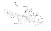
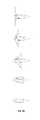
- FIG. 1is a perspective view of an aerial vehicle in forward flight according to a first embodiment of the present invention.
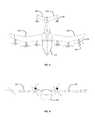
- FIG. 2is a side view of an aerial vehicle in a forward flight configuration according to a first embodiment of the present invention.
- FIG. 3is a top view of an aerial vehicle in a forward flight configuration according to a first embodiment of the present invention.
- FIG. 4is a front view of an aerial vehicle in a forward flight configuration according to a first embodiment of the present invention.
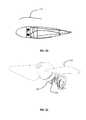
- FIG. 5is a perspective view of an aerial vehicle in takeoff configuration according to a first embodiment of the present invention.
- FIG. 6is a front view of an aerial vehicle in takeoff configuration according to a first embodiment of the present invention.
- FIG. 7is a side view of an aerial vehicle in takeoff configuration according to a first embodiment of the present invention.
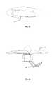
- FIG. 8is a perspective view of an aerial vehicle in a transition configuration according to a first embodiment of the present invention.
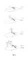
- FIG. 9is a sequence of views illustrating transition of the wing according to a first embodiment of the present invention.
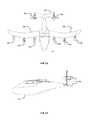
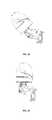
- FIG. 10is a perspective view of an aerial vehicle in forward flight with wing rotor blades stowed according to a first embodiment of the present invention.
- FIG. 11is a front view of an aerial vehicle in a forward flight configuration with wing rotor blades stowed according to a first embodiment of the present invention.
- FIG. 12is a top view of an aerial vehicle in a forward flight configuration with wing rotor blades stowed according to a first embodiment of the present invention.
- FIG. 13is a side view of an aerial vehicle in a forward flight configuration with wing rotor blades stowed according to a first embodiment of the present invention.
- FIG. 14is a perspective view of a wing rotor with the front cover removed for clarity according to some embodiments of the present invention.
- FIG. 15is a front view of a wing rotor with the front cover removed for clarity according to some embodiments of the present invention.
- FIG. 16is a side view of a wing rotor with its blades deployed according to some embodiments of the present invention.
- FIG. 17is a side view of a wing rotor with its blades stowing according to some embodiments of the present invention.
- FIG. 18is a side view of a wing rotor with its blades stowing according to some embodiments of the present invention.
- FIG. 19is a side view of a wing rotor with its blades stowing according to some embodiments of the present invention.
- FIG. 20is a side view of a wing rotor with its blades stowed according to some embodiments of the present invention.
- FIG. 21is a perspective view of a tail rotor according to some embodiments of the present invention.
- FIG. 22is a side view of a tail rotor in a forward flight configuration according to some embodiments of the present invention.
- FIG. 23is a side view of a tail rotor in a take-off configuration to some embodiments of the present invention.
- FIG. 24is a side view of a tail rotor and its deployment mechanism in a stowed configuration according to some embodiments of the present invention.
- FIG. 25is a side view of a tail rotor and its deployment mechanism moving from a stowed configuration according to some embodiments of the present invention.
- FIG. 26is a side view of a tail rotor and its deployment mechanism moving from a stowed configuration according to some embodiments of the present invention.
- FIG. 27is a side view of a tail rotor and its deployment mechanism in a deployed configuration according to some embodiments of the present invention.
- FIG. 28is a front view of a tail rotor and its deployment mechanism in a deployed configuration according to some embodiments of the present invention.
- FIG. 29is a perspective view of an aerial vehicle in take-off configuration according to a second embodiment of the present invention.
- FIG. 30is a front view of an aerial vehicle in take-off configuration according to a second embodiment of the present invention.
- FIG. 31is a side view of an aerial vehicle in take-off configuration according to a second embodiment of the present invention.
- FIG. 32is a top view of an aerial vehicle in take-off configuration according to a second embodiment of the present invention.
- FIG. 33is a perspective view of an aerial vehicle in a forward flight configuration according to a second embodiment of the present invention.
- FIG. 34is a front view of an aerial vehicle in a forward flight configuration according to a second embodiment of the present invention.
- FIG. 35is a side view of an aerial vehicle in a forward flight configuration according to a second embodiment of the present invention.
- FIG. 36is a top view of an aerial vehicle in a forward configuration according to a second embodiment of the present invention.
- FIG. 37is a side view illustrating nested blades according to some embodiments of the present invention.
- FIG. 38is a side view of a deployed rotor unit with rotor blades extended according to some embodiments of the present invention.
- FIG. 39is a side view of rotor unit with two blade sets in a forward flight mode according to some embodiments of the present invention.
- FIG. 40is a side view of rotor unit with two blade sets in a take-off mode according to some embodiments of the present invention.
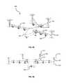
- FIG. 41is a front view of an electric motor according to some embodiments of the present invention.
- FIG. 42is a partial view of a directional clutch in an electric motor according to some embodiments of the present invention.
- FIG. 43is a partial view of a directional clutch in an electric motor according to some embodiments of the present invention.
- FIG. 44is a partial cross-sectional view of directional clutches in an electric motor according to some embodiments of the present invention.
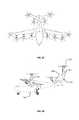
- FIG. 45is a perspective view of an aerial vehicle in take-off configuration according to a third embodiment of the present invention.
- FIG. 46is a front view of an aerial vehicle in take-off configuration according to a third embodiment of the present invention.
- FIG. 47is a top view of an aerial vehicle in take-off configuration according to a third embodiment of the present invention.
- FIG. 48is a side view of an aerial vehicle in take-off configuration according to a third embodiment of the present invention.
- FIG. 49is a perspective view of an aerial vehicle according to a fourth embodiment of the present invention.
- FIG. 50is a front view of an aerial vehicle in a take-off configuration according to a fourth embodiment of the present invention.
- FIG. 51is a top view of an aerial vehicle in a take-off configuration according to a fourth embodiment of the present invention.
- FIG. 52is a side view of an aerial vehicle in a take-off configuration according to a fourth embodiment of the present invention.
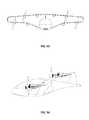
- FIG. 53is a perspective view of an aerial vehicle in a forward flight configuration according to a fourth embodiment of the present invention.
- FIG. 54is a top view of an aerial vehicle in a forward flight configuration according to a fourth embodiment of the present invention.
- FIG. 55is a front view of an aerial vehicle in a forward flight configuration according to a fourth embodiment of the present invention.
- FIG. 56is a side view of an aerial vehicle in a forward flight configuration according to a fourth embodiment of the present invention.
- VTOLvertical takeoff and landing
- the thrust needed for VTOLis significantly higher than the thrust needed to maintain horizontal flight.
- the vertical take-off thrustmay also be needed during the transition to forward flight.
- the wings of the aircraftOnce moving in forward flight, the wings of the aircraft provide lift, supplanting a function delivered by motors during VTOL and during transition.
- Thrust producing elements needed during take-off, but not during forward flight,may be altered during forward flight such that they impart less drag onto the flying system.
- an aerial vehiclemay use bladed propellers powered by electric motors to provide thrust during take-off.
- the propeller/motor unitsmay be referred to as rotor assemblies.
- the wings of the aerial vehiclemay rotate, with the leading edges facing upwards, such that the propellers provide vertical thrust for take-off and landing.
- the motor driven propeller units on the wingsmay themselves rotate relative to a fixed wing, such that the propellers provide vertical thrust for take-off and landing.
- the rotation of the motor driven propeller unitsmay allow for directional change of thrust by rotating both the propeller and the electric motor, thus not requiring any gimbaling, or other method, of torque drive around or through a rotating joint.
- some or all of the wing mounted motor driven rotorsare adapted to have the rotor blades fold back into a stowed position wherein the blades nest in recesses in the adjoining nacelle body after a transition to horizontal flight.
- the nested bladesmay result in a significantly lower drag of the aerial vehicle, while also allowing a significantly reduced power usage with only some of the rotors providing forward thrust.
- extended nacelles with two coaxial propellersare used such that one of the propellers is used during forward flight, and another during vertical take-off and landing.
- the VTOL propellermay be adapted to nest its blades during forward flight.
- the extended nacellemay reside at the tip of a wing, or at the end of a rear V-tail element, and be adapted to rotate such that the VTOL propeller may provide vertical thrust during take-off and landing.
- each of the coaxial propellershas its own electric motor.
- the coaxial propellersare driven by the same electric motor.
- the electric motorhas directional clutches such that one propeller is driven while the motor rotates in a first direction, and the other propeller is driven while the motor rotates in a second direction.
- the motor driven rotors attached to the wingare adapted to place the mass of the motor and rotor significantly forward of the wing.
- this forward locationallows for the rotation of the rotors to a vertical thrust orientation that has the airflow predominantly in front of the leading edge of the wing, reducing air flow impingement by the wing during VTOL operations.
- this forward location of the mass of the rotors and motorsallows for unusual wing configurations, such as swept forward wings, whose otherwise possible drawbacks during higher g-force maneuvers are partially or fully moderated by this mass placement.
- the mass balance of the aerial vehiclemay be altered by movement of masses such as the battery mass.
- the battery massmay be adjusted to retain balance when a single vs. a multi-passenger load is supported.
- mass balancemay be adjusted in automatic response to sensors within the aerial vehicle.
- the battery massmay be distributed between a two or more battery packs. The battery packs may be mounted such that their position may be changed during flight in response to changes in the balance of the aerial vehicle.
- the flight control system of the aerial vehiclemay sense differential thrust requirements during vertical take-off and landing, and may move the battery mass in order to achieve a more balanced thrust distribution across the rotor assemblies.
- the battery massmay be moved should there be a failure of a rotor assembly during transition or vertical take-off and landing, again to balance the thrust demands of the various remaining functioning rotors.
- an aerial vehicle 100is seen in first forward flight configuration, as would be seen just after having transitioned from a vertical take-off configuration.
- the blades of the wing mounted rotorswill stow and nest, as discussed below.
- the aircraft body 101supports a left wing 102 and a right wing 103 .
- Motor driven rotor units 106include propellers 107 which may stow and nest into the nacelle body.
- the aircraft body 101extends rearward is also attached to raised rear stabilizers 104 .
- the rear stabilizershave rear motors 105 attached thereto. In some aspects, the rear motors may also have front hubs, or spinners, which are omitted from some Figures for illustrative purposes.
- the wings 102 , 103are partially swept forward.
- Aerial vehicles according to embodiments of the present inventionmay include partially or wholly forward swept wings with spanwise distributed masses located forward of the leading edge.
- the divergent aeroelastic torsion commonly seen in forward-swept wing designsis substantially reduced by the presence of the masses cantilevered forward of the wing, which create opposing torque.
- the wing rotor assemblies 106are mounted forward of the wing leading edge, and are also then forward of the neutral axis of the wing.
- FIGS. 5-7illustrate the aerial vehicle 100 in a vertical take-off and landing configuration such that the thrust of the rotors is directed upward.
- the wing 102 , 103have been rotated relative to the body 101 around a pivot 108 .
- the wingsare fixed to each other with structure that crosses through the vehicle body 101 .
- the attachment of the wing to the aerial vehicle bodymay use a linkage adapted to maintain a forward position of the mass of the wing and rotor assemblies.
- FIGS. 21-28illustrate the configurations of the rear rotor.
- the deployment of a rear rotor from a stowed, forward flight, configuration to a deployed, vertical take-off, position, as well as a variety of intervening positions,may be achieved using a deployment mechanism which rotates the rotor relative to the rear stabilizers.
- FIG. 22illustrates a stowed, forward flight, configuration of rear rotor unit 105 .
- the rear nacelle portion 115may be rigidly mounted to a rear stabilizer in some embodiments.
- the spinner 114 and the motor cover 113provide aerodynamic surfaces for the front portion of the nacelle.
- the propeller 111extends through the spinner 114 . In a fully deployed position, as seen in FIG.
- the motor 110 , motor cover 113 , spinner 114 , and propeller 111have rotated to a position adapted to provide vertical thrust.
- the electric motor/propeller combinationbeing on the outboard side of the articulating joint allows for a rigid mounting of the propeller to the motor, which is maintained even as the propeller is moved through various attitudes relative to the rear nacelle portion. With such a configuration the rotating power from the motor need not be gimbaled or otherwise transferred across a rotating joint.
- FIGS. 24-27illustrate a sequence of positions of the motor and propeller relative to the rear nacelle, also to the rear tail structure of the aerial vehicle.
- the linkagesfirst deploy the articulating portion forward, as opposed to merely pivoting around a single pivot point.
- the multi-bar linkageallows for the use of a single actuator for this complex deployment.
- FIG. 26illustrates the rear rotor unit as it does rise above the top of the rear nacelle, and achieves full deployment as seen in FIG. 27 .
- the motion of the articulating portionwhich includes the motor, propeller, and spinner, is almost horizontal at the position of full deployment.
- the actuator powering the deployment of the multi-bar linkageis not required to offset, or counteract, the thrust of the rotor.
- FIG. 9illustrates various positions of the wing and rear rotors as would be seen during transition from take-off to forward flight mode, or from forward flight mode to vertical take-off and landing mode.
- the rotorstransition from a configuration providing vertical thrust through positions rotating towards the horizontal.
- the wingsbegin to generate lift such that not as much vertical thrust is needed to maintain altitude. With sufficient forward speed, lift is maintained by the wings and the thrust needed for forward flight is able to be provided by fewer rotors.
- the wingsare raised to a vertical take-off configuration with the use of a linkage adapted to slide the wing pivot forward as the wing reaches deployment. This allows for a more favorable compromise in center of gravity location between VTOL and forward flight modes by locating the wing-mounted rotor assemblies farther forward in the VTOL configuration.
- FIGS. 10-13illustrate a forward flight configuration of the aerial vehicle 100 according to some embodiment of the present invention.
- the propeller blades of the wing mounted rotors 106have been stowed and are nested within recesses along the nacelle.
- many of the individual motors and rotorsmay be deactivated during forward flight.
- the bladesmay be folded back into a stowed position.
- the nacellesmay have recesses such that the folded blades are adapted to nest within the recesses, creating a very low drag nacelle during forward flight.
- the rear rotors 105may be used to provide forward thrust during this forward flight configuration.
- FIG. 14illustrates a front set of views of a stowing blade set as it stows from a fully deployed configuration to a fully stowed configuration.
- the bladesnest into recesses along the nacelle such that the stowed blade set gives the effective wetted area of a simple nacelle.
- FIG. 15illustrates a wing mounted rotor unit according to some embodiments as it stows from a fully deployed configuration to a stowed configuration.
- the rotor assemblywhich may comprise an electric motor, the blade set, and the spinner, may itself deploy as a whole as seen in FIG. 38 , for example.
- the deployment of the rotor assemblyutilizes a linkage, such as the linkage 209 of FIG. 38 , which deploys the rotor to a vertical position while simultaneously pushing it forward and away from the remaining body of the nacelle.
- the push away from the remaining body of the nacellereduces the download in the wing from the downwash of the associated rotor.
- FIGS. 16-20illustrate a sequence of positions as the blades 107 of a wing mounted rotor 106 fold down into a stowed position.
- FIG. 16illustrates the propeller blades 107 fully deployed, as would be used in vertical take-off and landing, and during transition to horizontal, forward, flight. Thus succeeding figures illustrate the blades 107 folding down to a stowed position. As seen in FIG. 20 , the blades 107 fit within recesses 116 in the nacelle resulting in a low drag configuration 117 .
- the aerial vehiclehas 8 rotors and weighs 900 kg.
- the rotor diametersare 1.3 meters, with a thrust per rotor of 1100 N.
- the continuous rpm of the motor at sea levelis 1570 rpm, with a maximum of 1920 rpm.
- the wingspanis 8.5 meters.
- the battery massis 320 kg, and the mass per motor is 20 kg.
- the cruise speedis 320 km/h.
- the continuous hover shaft power per motoris 29 kW.
- an aerial vehicle 200uses forward swept fixed wings 202 , 203 with rotors of different types adapted for both vertical take-off and landing and for forward flight.
- the aircraft body 201supports a left wing 202 and a right wing 203 .
- Motor driven rotor assemblies 206 , 207 on the wingsinclude propellers which may stow and nest into the nacelle body.
- the aircraft body 201extends rearward is also attached to raised rear stabilizers 204 .
- the rear stabilizershave rear rotor assemblies 205 , 208 attached thereto.
- the aerial vehicle 200is seen with two passenger seats side by side, as well as landing gear under the body 201 . Although two passenger seats are illustrated, other numbers of passengers may be accommodated in differing embodiments of the present invention.
- Aerial vehiclesmay include partially or wholly forward swept wings with spanwise distributed masses located forward of the leading edge.
- the divergent aeroelastic torsion commonly seen in forward-swept wing designsis substantially reduced by the presence of the masses cantilevered forward of the wing, which create opposing torque.
- the propellers of the wing mounted motor driven rotor unitsare extended forward with, and from, their nacelles such that the air flow in vertical take-off mode is not substantially interfered with by the wings.
- the propellers of the rear stabilizer mounted motor driven rotor unitsare extended forward with, and from, their nacelles such that the air flow in vertical take-off mode is not substantially interfered with by the rear stabilizers.
- An illustration of the linkage that may be used to extend the rotors in the vertical configurationmay be seen in FIG. 38 .
- a further aspect of the forward swept wing configurationis that it allows for the wings 202 , 203 to be mounted to the body 201 somewhat rearward of where they may have attached otherwise. The rearward attachment allows for a spar connecting the wings to traverse the interior of the aerial vehicle body to the rear of the passenger seats.
- a further aspect of the forward swept wing with articulating rotors in VTOL modeis the forward stagger of the vertical rotors, which improves longitudinal control authority in vertical and transitional flight for a given wing root location by lengthening the moment arm of these rotors about the center of gravity. This is especially helpful in the case of a failure in one of the rear mounted rotors during VTOL modes. Additionally, the more even longitudinal rotor distribution effected by this configuration reduces the highest torque of the motors required to maintain level vertical flight in worst-case single motor or rotor failure eventuality, allowing the motor size to be reduced.
- a portion of the wing mounted rotorsmay be adapted to be used in a forward flight configuration, while other wing mounted rotors may be adapted to be fully stowed during regular, forward, flight.
- the aerial vehicle 200may have four rotors on the right wing 203 and four rotors on the left wing 202 .
- Three of the rotor assemblies on each wingmay have wing mounted rotors 206 that are adapted to flip up into a deployed position for vertical take-off and landing, to be moved back towards a stowed position during transition to forward flight, and then to have their blades stowed, and nested, during forward flight.
- the fourth rotor assembly 207may include a second set of blades to be used for forward flight, as discussed below.
- the each rear stabilizer 204may be have two rotor units mounted to it, both of which are adapted to be used during vertical take-off and landing, and transition, modes, but one of which is adapted to be fully stowed as low drag nacelle during forward flight.
- a multi-modal wing mounted rotor unit 207is adapted to use a first set of blades 212 for forward flight, and a second set of blades 213 for VTOL and transitional flight modes.
- the forward flight blades 212may be coaxial to the VTOL blades 213 , and may be attached at different ends of the same nacelle. In the case wherein the VTOL blades are articulated to a vertical position for VTOL flight modes, there may be two motors within the nacelle, one for each blade set.
- a multi-modal rear mounted rotor unit 210is adapted to use a first set of blades 211 for forward flight, and a second set of blades 214 for VTOL and transitional flight modes.
- the forward flight blades 211may be coaxial to the VTOL blades 214 , and may be attached at different ends of the same nacelle. In the case wherein the VTOL blades are articulated to a vertical position for VTOL flight modes, there may be two motors within the nacelle, one for each blade set.
- all of the blades used to provide thrust for VTOL and transitional modesare stowed during forward flight, and different blades are used to provide thrust during forward flight.
- a single motoris used to provide power for different blade sets depending upon whether VTOL or forward flight modes are being used.
- two blade setsare placed in a coaxial configuration such that they are supported by a single nacelle, for example.
- FIGS. 33-36illustrate an aerial vehicle 200 in a forward flight mode wherein all of the VTOL blades have been stowed, and nested in recesses, such that the nacelles present low drag.
- the wing mounted rotor units 206 , 207are seen with all of the VTOL blades stowed.
- the rear mounted rotor units 205 , 208also have their VTOL blades stowed.
- the forward flight blade set 211 of the multi-modal rear rotor assemblies 205 and the forward flight blade set 212 of the multi-modal wing rotor assemblies 207are used to provide thrust during forward flight.
- FIGS. 39 and 40illustrate a motor and rotor unit 260 adapted to use a first set of blades 261 for a forward flight mode and a second set of blades 263 for VTOL and transition modes, in a coaxial configuration that shares a single motor for both blade sets.
- both bladesare powered by the same electric motor.
- the electric motormay be adapted with directional clutches such that when the motor is rotated in a first direction the forward flight blades 261 are engaged, and the VTOL blades 263 are idled.
- the VTOL blades 264may stow and may nest in recesses 264 .
- the motormay rotate in a second direction such that the VTOL blades 264 are engaged, and the forward flight blades 261 are disengaged.
- the motor and rotor assemblymay be articulated such that the rotors and motor provide vertical thrust, with the entire motor and clutching unit, as well as both sets of blades, outboard of the positioning mechanism, such that no mechanical power related to blade thrust need traverse the gimbaled joint.
- FIGS. 41-44illustrate a motor 265 with directional clutches 266 , 267 adapted to power a first set of blades when the motor is rotated in a first direction, and to power a second set of blades when the motor is rotated in a second direction.
- the VTOL blade set and the forward flight blade setmay be oriented in different directions such that they both provide thrust in the same direction, although one set is engaged when the motor rotates in a first direction, and the second set is engaged when the motor rotates in a second direction.
- an aerial vehicle 300uses forward swept wings 302 , 303 with rotors of different types adapted for both vertical take-off and landing and for forward flight.
- the aircraft body 301supports a left wing 302 and a right wing 303 .
- Motor driven rotor assemblies 306 , 307 on the wingsinclude propellers which may stow and nest into the nacelle body.
- the aircraft body 301extends rearward and is also attached to raised rear stabilizers 304 .
- the rear stabilizershave rear rotor assemblies 305 , 308 attached thereto.
- the aerial vehicle 300is adapted for two passenger seats side by side, as well as landing gear under the body 301 .
- the wing mounted rotor units 306 , 307are adapted to provide vertical thrust during take-off and landing modes.
- the inner rotor units 306are adapted to deploy to a VTOL configuration using linkages as seen in FIG. 38 .
- the blades of the inner wing rotor units 306are adapted to stow when in a forward flight configuration, with the blades nested into recesses in the nacelle.
- the wing tip rotor units 307are adapted to rotate relative to the wing such that the nacelle maintains its shape whether in a VTOL or a forward flight configuration.
- the VTOL blades 313are used for VTOL and transition modes, and the forward flight blades 312 are used for forward flight, with the VTOL blades stowed and nested.
- the nacellethat maintains its shape allows for the use of a single motor to power either of the blade sets.
- the motormay use directional clutches such that the motor direction determines which of the blade sets is powered.
- the blades of the inner tail rotor units 308are adapted to stow when in a forward flight configuration, with the blades nested into recesses in the nacelle.
- the rear tip rotor units 305are adapted to rotate relative to the wing such that the nacelle maintains its shape whether in a VTOL or a forward flight configuration.
- the VTOL blades 314are used for VTOL and transition modes, and the forward flight blades 311 are used for forward flight, with the VTOL blades stowed and nested.
- the aerial vehiclehas 12 rotors and weighs 900 kg.
- the rotor diameteris 1.1 meters, with a thrust per rotor of 736 N.
- the continuous rpm of the motor at sea levelis 1850 rpm, with a maximum of 2270 rpm.
- the wingspanis 8.9 meters.
- the battery massis 320 kg, and the mass per motor is 9 kg.
- the cruise speedis 320 km/h.
- the continuous hover power per motoris 19 shaft kW.
- FIGS. 49-52illustrate a fourth embodiment of an aerial vehicle 400 in a take-off configuration.
- a box wing designis seen with the rotor assemblies deployed into vertical take-off configuration.
- FIGS. 53-56illustrate a fourth embodiment of an aerial vehicle 400 in a forward flight configuration. As seen the rotor assemblies are rotated into a forward flight configuration. Some of the blades of the rotor assemblies have been stowed to reduce drag in this forward flight mode.
- aerial vehiclestake-off from the ground with vertical thrust from rotor assemblies that have deployed into a vertical configuration.
- the rotor assembliesmay begin to be tilted forward in order to begin forward acceleration.
- airflow over the wingsresults in lift, such that the rotors become unnecessary for maintaining altitude using vertical thrust.
- some or all of the blades used for providing vertical thrust during take-offmay be stowed along their nacelles.
- the nacelle supporting the rotor assembliesmay have recesses such that the blades may nest into the recesses, greatly reducing the drag of the disengaged rotor assemblies.
Landscapes
- Engineering & Computer Science (AREA)
- Aviation & Aerospace Engineering (AREA)
- Mechanical Engineering (AREA)
- Chemical & Material Sciences (AREA)
- Combustion & Propulsion (AREA)
- Other Liquid Machine Or Engine Such As Wave Power Use (AREA)
- Wind Motors (AREA)
- Toys (AREA)
- Fittings On The Vehicle Exterior For Carrying Loads, And Devices For Holding Or Mounting Articles (AREA)
- Hydraulic Turbines (AREA)
Abstract
Description
Claims (12)
Priority Applications (18)
| Application Number | Priority Date | Filing Date | Title |
|---|---|---|---|
| US14/660,771US10625852B2 (en) | 2014-03-18 | 2015-03-17 | Aerodynamically efficient lightweight vertical take-off and landing aircraft with pivoting rotors and stowing rotor blades |
| CN202110329851.0ACN112896501B (en) | 2014-03-18 | 2015-03-18 | A vehicle suitable for vertical takeoff and horizontal flight |
| EP23218066.1AEP4324740A3 (en) | 2014-03-18 | 2015-03-18 | Erodynamically efficient lightweight vertical take-off and landing aircraft with pivoting rotors and stowable rotor blades |
| PCT/US2015/021350WO2015143098A2 (en) | 2014-03-18 | 2015-03-18 | Aerodynamically efficient lightweight vertical take-off and landing aircraft with pivoting rotors and stowing rotor blades |
| JP2016557961AJP6632542B2 (en) | 2014-03-18 | 2015-03-18 | Aerodynamically efficient lightweight vertical take-off and landing aircraft with swirling rotor blades and contained rotor blades |
| JP2016557960AJP6630286B2 (en) | 2014-03-18 | 2015-03-18 | Aerodynamically efficient lightweight vertical takeoff and landing aircraft with swirling rotor blades and contained rotor blades |
| CN201580026092.3ACN106573678B (en) | 2014-03-18 | 2015-03-18 | Aircraft suitable for vertical take-off and horizontal flight |
| CN201580025370.3ACN106573677B (en) | 2014-03-18 | 2015-03-18 | Aerodynamically efficient light vertical take-off and landing aircraft with pivoting rotors and retracting rotor blades |
| EP15765196.9AEP3119674B1 (en) | 2014-03-18 | 2015-03-18 | Impact resistant propeller system |
| EP15765064.9AEP3119673B1 (en) | 2014-03-18 | 2015-03-18 | Aerodynamically efficient lightweight vertical take-off and landing aircraft with pivoting rotors and stowing rotor blades |
| PCT/US2015/021344WO2015143093A2 (en) | 2014-03-18 | 2015-03-18 | Aerodynamically efficient lightweight vertical take-off and landing aircraft with pivoting rotors and stowing rotor blades |
| EP24172745.2AEP4417510A3 (en) | 2014-03-18 | 2015-03-18 | Aerodynamically efficient lightweight vertical take-off and landing aircraft with pivoting rotors and stowing rotor blades |
| EP20203070.6AEP3798123B1 (en) | 2014-03-18 | 2015-03-18 | Aerodynamically efficient lightweight vertical take-off and landing aircraft with pivoting rotors and stowing rotor blades |
| CN202010840186.7ACN112061389A (en) | 2014-03-18 | 2015-03-18 | Pneumatically efficient lightweight vertical takeoff and landing aircraft with pivoting rotors and furled rotor blades |
| EP20194551.6AEP3778388B1 (en) | 2014-03-18 | 2015-03-18 | Erodynamically efficient lightweight vertical take-off and landing aircraft with pivoting rotors and stowable rotor blades |
| JP2019213745AJP6878555B2 (en) | 2014-03-18 | 2019-11-26 | Aerodynamically efficient lightweight vertical takeoff and landing aircraft with swivel rotorcraft and contained rotorcraft |
| JP2019221045AJP6900459B2 (en) | 2014-03-18 | 2019-12-06 | Aerodynamically efficient lightweight vertical takeoff and landing aircraft with swivel rotorcraft and contained rotorcraft |
| JP2021075145AJP7124164B2 (en) | 2014-03-18 | 2021-04-27 | Aerodynamically efficient lightweight vertical take-off and landing aircraft with swiveling rotors and stowed rotor blades |
Applications Claiming Priority (2)
| Application Number | Priority Date | Filing Date | Title |
|---|---|---|---|
| US14/218,845US9694911B2 (en) | 2014-03-18 | 2014-03-18 | Aerodynamically efficient lightweight vertical take-off and landing aircraft with pivoting rotors and stowing rotor blades |
| US14/660,771US10625852B2 (en) | 2014-03-18 | 2015-03-17 | Aerodynamically efficient lightweight vertical take-off and landing aircraft with pivoting rotors and stowing rotor blades |
Related Parent Applications (1)
| Application Number | Title | Priority Date | Filing Date |
|---|---|---|---|
| US14/218,845ContinuationUS9694911B2 (en) | 2014-03-18 | 2014-03-18 | Aerodynamically efficient lightweight vertical take-off and landing aircraft with pivoting rotors and stowing rotor blades |
Publications (2)
| Publication Number | Publication Date |
|---|---|
| US20160031555A1 US20160031555A1 (en) | 2016-02-04 |
| US10625852B2true US10625852B2 (en) | 2020-04-21 |
Family
ID=54145473
Family Applications (1)
| Application Number | Title | Priority Date | Filing Date |
|---|---|---|---|
| US14/660,771ActiveUS10625852B2 (en) | 2014-03-18 | 2015-03-17 | Aerodynamically efficient lightweight vertical take-off and landing aircraft with pivoting rotors and stowing rotor blades |
Country Status (5)
| Country | Link |
|---|---|
| US (1) | US10625852B2 (en) |
| EP (3) | EP3119673B1 (en) |
| JP (2) | JP6630286B2 (en) |
| CN (2) | CN112896501B (en) |
| WO (1) | WO2015143093A2 (en) |
Cited By (13)
| Publication number | Priority date | Publication date | Assignee | Title |
|---|---|---|---|---|
| US20210122466A1 (en)* | 2019-10-28 | 2021-04-29 | Uber Technologies, Inc. | Aerial vehicle with differential control mechanisms |
| US20210253237A1 (en)* | 2018-05-10 | 2021-08-19 | Joby Aero, Inc. | Electric tiltrotor aircraft |
| US20210371093A1 (en)* | 2018-03-31 | 2021-12-02 | Dr. Nakamats Innovation Institute | Aerial vehicle such as high speed drone |
| US11472546B2 (en)* | 2020-02-24 | 2022-10-18 | Aurora Flight Sciences Corporation | Fixed-wing short-takeoff-and-landing aircraft and related methods |
| US11554865B2 (en) | 2020-02-18 | 2023-01-17 | Aurora Flight Sciences Corporation | Vertical take-off and landing (VTOL) aircraft and related methods |
| US20230091659A1 (en)* | 2021-06-21 | 2023-03-23 | Mesos LLC | High-Altitude Airborne Remote Sensing |
| USD988226S1 (en)* | 2021-02-24 | 2023-06-06 | Joby Aero, Inc. | Aircraft |
| US11772773B2 (en) | 2021-01-04 | 2023-10-03 | Aurora Flight Sciences Corporation, a subsidiary of The Boeing Company | Aircraft and related methods |
| USD1009696S1 (en) | 2020-02-18 | 2024-01-02 | Aurora Flight Sciences Corporation, a subsidiary of The Boeing Company | Aircraft |
| US20240109657A1 (en)* | 2022-09-30 | 2024-04-04 | Wing Aviation Llc | Uav with distributed propulsion and blown control surfaces |
| EP4261126A4 (en)* | 2020-12-14 | 2024-05-29 | Panasonic Intellectual Property Management Co., Ltd. | ENGINE UNIT AND AIRCRAFT |
| US12097948B2 (en) | 2021-09-09 | 2024-09-24 | Israel Aerospace Industries Ltd. | Propulsion system |
| US12420922B2 (en) | 2021-07-31 | 2025-09-23 | Supernal, Llc | Vertical take-off and landing craft systems and methods |
Families Citing this family (85)
| Publication number | Priority date | Publication date | Assignee | Title |
|---|---|---|---|---|
| US10625852B2 (en)* | 2014-03-18 | 2020-04-21 | Joby Aero, Inc. | Aerodynamically efficient lightweight vertical take-off and landing aircraft with pivoting rotors and stowing rotor blades |
| US10513332B2 (en)* | 2015-10-05 | 2019-12-24 | Sikorsky Aircraft Corporation | Tiltwing aircraft |
| CN105235892B (en)* | 2015-10-21 | 2017-11-24 | 北京航空航天大学 | A kind of multi-modal flight switching control method of mixed layout rotor wing unmanned aerial vehicle |
| CN105217024B (en)* | 2015-10-30 | 2017-10-10 | 佛山市神风航空科技有限公司 | A kind of axle aircraft of symmetric form six |
| CN105292462B (en)* | 2015-10-30 | 2017-12-05 | 佛山市神风航空科技有限公司 | A kind of Multi-axis aircraft |
| CN105217028A (en)* | 2015-10-30 | 2016-01-06 | 佛山市神风航空科技有限公司 | A kind of compound type autogiro |
| CN105217026B (en)* | 2015-10-30 | 2017-12-19 | 佛山市神风航空科技有限公司 | A kind of compound aircraft |
| CN105217023B (en)* | 2015-10-30 | 2017-12-12 | 佛山市神风航空科技有限公司 | A kind of four axle glide vehicles |
| US20170283048A1 (en)* | 2016-03-29 | 2017-10-05 | Amazon Technologies, Inc. | Convertable lifting propeller for unmanned aerial vehicle |
| CA2967221C (en)* | 2016-05-13 | 2021-08-24 | Bell Helicopter Textron Inc. | Forward folding rotor blades |
| CA2967228C (en)* | 2016-05-13 | 2020-08-25 | Bell Helicopter Textron Inc. | Vertical take off and landing closed wing aircraft |
| US10676183B2 (en) | 2016-05-13 | 2020-06-09 | Bell Helicopter Textron Inc. | Forward folding rotor blades |
| GB2550916B (en)* | 2016-05-30 | 2018-09-26 | Kapeter Luka | Propeller-hub assembly with folding blades for VTOL aircraft |
| US10392106B2 (en)* | 2016-09-08 | 2019-08-27 | General Electric Company | Tiltrotor propulsion system for an aircraft |
| US10384774B2 (en) | 2016-09-08 | 2019-08-20 | General Electric Company | Tiltrotor propulsion system for an aircraft |
| US10252797B2 (en)* | 2016-09-08 | 2019-04-09 | General Electric Company | Tiltrotor propulsion system for an aircraft |
| EP3315400A1 (en)* | 2016-10-25 | 2018-05-02 | AeroMobil R&D, s. r. o. | Folding propeller |
| US9783288B1 (en)* | 2016-12-07 | 2017-10-10 | Kitty Hawk Corporation | Lift fan position lock mechanism |
| KR101913931B1 (en)* | 2017-02-24 | 2018-10-31 | 기술융합협동조합 | Vertical takeoff and landing aircraft and transition method |
| US9957042B1 (en) | 2017-03-01 | 2018-05-01 | Kitty Hawk Corporation | Bimodal propeller aircraft |
| CN106965928A (en)* | 2017-03-08 | 2017-07-21 | 贾杰 | The rotatable wing vertically taking off and landing flyer of multistage |
| EP3583027A4 (en)* | 2017-03-09 | 2020-03-04 | Shafir, Yehuda | VERTICAL STARTING AND LANDING LIGHT AIRCRAFT |
| FR3065440B1 (en)* | 2017-04-24 | 2019-06-07 | Fly-R | VERTICAL LANDING AIRCRAFT RHOMBOEDRICAL VESSEL |
| US10259563B2 (en) | 2017-05-19 | 2019-04-16 | Kitty Hawk Corporation | Combined fan and motor |
| KR102627083B1 (en)* | 2017-05-22 | 2024-01-18 | 오버에어, 인코퍼레이티드 | Evtol aircraft using large, variable speed tilt rotors |
| US10974826B2 (en)* | 2017-05-22 | 2021-04-13 | Overair, Inc. | EVTOL having many variable speed tilt rotors |
| EP3412567A1 (en)* | 2017-06-08 | 2018-12-12 | Airbus Defence and Space GmbH | Aerial vehicle |
| US10967967B2 (en)* | 2017-08-30 | 2021-04-06 | The Boeing Company | Systems and methods for winged drone platform |
| US10994829B2 (en)* | 2017-09-22 | 2021-05-04 | The Boeing Company | Foldable rotor assembly for fixed-wing VTOL aircraft |
| WO2019056053A1 (en)* | 2017-09-22 | 2019-03-28 | AMSL Innovations Pty Ltd | Wing tilt actuation system for electric vertical take-off and landing (vtol) aircraft |
| CN109552616A (en)* | 2017-09-27 | 2019-04-02 | 周建卫 | Novel unmanned plane |
| KR101803059B1 (en)* | 2017-09-28 | 2017-11-29 | 홍승일 | Vertical takeoff and landing airplane |
| US9975631B1 (en) | 2017-11-01 | 2018-05-22 | Kitty Hawk Corporation | Tiltwing multicopter with foldable and non-foldable propellers |
| JP2019085104A (en)* | 2017-11-06 | 2019-06-06 | 株式会社エアロネクスト | Flying body and method of controlling flying body |
| US10696391B2 (en) | 2017-11-16 | 2020-06-30 | Textron Innovations Inc. | Extended range quad tiltrotor aircraft |
| US10752352B2 (en) | 2017-12-07 | 2020-08-25 | Textron Innovations Inc. | Dual rotor propulsion systems for tiltrotor aircraft |
| WO2019116101A1 (en)* | 2017-12-12 | 2019-06-20 | Spencer Cameron | Variable-geometry vertical take-off and landing (vtol) aircraft system |
| WO2019142014A1 (en) | 2018-01-18 | 2019-07-25 | Aerones, Sia | An electric drone glider arrangement |
| RU2682756C1 (en)* | 2018-03-05 | 2019-03-21 | Общество с ограниченной ответственностью "Техноветер" | Convertible plane |
| US11008093B2 (en)* | 2018-03-22 | 2021-05-18 | Aurora Flight Sciences Corporation | Systems and methods for reducing the propeller noise |
| JP7671040B2 (en)* | 2018-03-31 | 2025-05-01 | 義郎 中松 | Rotating wing vertical take-off and landing long-range aircraft |
| GB201806277D0 (en)* | 2018-04-17 | 2018-05-30 | Flugauto Holding Ltd | Vertical take-off and landing vehicle |
| US12044699B2 (en) | 2018-04-24 | 2024-07-23 | Fuelle Landing Systems, Inc. | Ground-based vectored thrust system |
| US12006048B2 (en) | 2018-05-31 | 2024-06-11 | Joby Aero, Inc. | Electric power system architecture and fault tolerant VTOL aircraft using same |
| CN112368208A (en) | 2018-05-31 | 2021-02-12 | 杰欧比飞行有限公司 | Electric power system architecture and fault-tolerant VTOL (virtual volume on-board) aircraft using same |
| KR102480033B1 (en) | 2018-06-01 | 2022-12-21 | 조비 에어로, 인크. | Systems and methods for aircraft noise abatement |
| US10710741B2 (en) | 2018-07-02 | 2020-07-14 | Joby Aero, Inc. | System and method for airspeed determination |
| US10322814B1 (en)* | 2018-09-01 | 2019-06-18 | Autoflightx International Limited | Aircraft vertical stabilizer having a lift propeller and the method of using the same |
| US11077940B2 (en)* | 2018-09-05 | 2021-08-03 | Stian Nilsen | Aircraft and method of use |
| US11198515B2 (en)* | 2018-09-11 | 2021-12-14 | Embraer S.A. | Method and system for distributed electrical loads connected to shared power sources |
| EP3853736A4 (en) | 2018-09-17 | 2022-11-16 | Joby Aero, Inc. | AIRCRAFT CONTROL SYSTEM |
| US11912405B2 (en) | 2018-10-02 | 2024-02-27 | Embraer S.A. | Vertical and short takeoff and landing (VSTOL) aircraft |
| EP3656669B1 (en)* | 2018-11-26 | 2021-01-13 | AIRBUS HELICOPTERS DEUTSCHLAND GmbH | A vertical take-off and landing multirotor aircraft with at least eight thrust producing units |
| WO2020180373A2 (en) | 2018-12-07 | 2020-09-10 | Joby Aero, Inc. | Aircraft control system and method |
| US20200331602A1 (en) | 2018-12-07 | 2020-10-22 | Joby Aero, Inc. | Rotary airfoil and design method therefor |
| WO2020132332A1 (en) | 2018-12-19 | 2020-06-25 | Joby Aero, Inc. | Vehicle navigation system |
| EP3670323B1 (en)* | 2018-12-19 | 2021-02-17 | LEONARDO S.p.A. | Aircraft and related manufacturing method |
| JP7094232B2 (en)* | 2019-01-22 | 2022-07-01 | 愛三工業株式会社 | Multicopter |
| EP3702277B1 (en)* | 2019-02-27 | 2021-01-27 | AIRBUS HELICOPTERS DEUTSCHLAND GmbH | A multirotor aircraft that is adapted for vertical take-off and landing (vtol) |
| EP3702276B1 (en) | 2019-02-27 | 2021-01-13 | AIRBUS HELICOPTERS DEUTSCHLAND GmbH | A multirotor joined-wing aircraft with vtol capabilities |
| JP1658121S (en) | 2019-03-11 | 2020-04-20 | ||
| US11230384B2 (en) | 2019-04-23 | 2022-01-25 | Joby Aero, Inc. | Vehicle cabin thermal management system and method |
| CN116646641B (en) | 2019-04-23 | 2024-09-13 | 杰欧比飞行有限公司 | Battery thermal management system and method |
| US10988248B2 (en) | 2019-04-25 | 2021-04-27 | Joby Aero, Inc. | VTOL aircraft |
| GB2585864B (en) | 2019-07-18 | 2022-04-27 | Gkn Aerospace Services Ltd | An aircraft |
| US11305872B2 (en)* | 2019-07-29 | 2022-04-19 | Aurora Flight Sciences Corporation | Retractable propulsor assemblies for vertical take-off and landing (VTOL) aircraft |
| US10981648B2 (en) | 2019-08-02 | 2021-04-20 | Kitty Hawk Corporation | Fixed wing aircraft with trailing rotors and T-tail |
| EP4592189A3 (en) | 2019-10-09 | 2025-09-03 | Kitty Hawk Corporation | Hybrid power systems for different modes of flight |
| CN110901906B (en)* | 2019-12-04 | 2023-04-25 | 中国直升机设计研究所 | Ground effect rotor craft and flight mode switching method |
| CN110901890A (en)* | 2019-12-04 | 2020-03-24 | 中国直升机设计研究所 | High-speed rotor craft with rotor capable of being designed in classification mode |
| JP7630526B2 (en)* | 2020-02-10 | 2025-02-17 | ウィスク アエロ エルエルシー | Aircraft with pusher propellers |
| USD945947S1 (en) | 2020-02-24 | 2022-03-15 | Aurora Flight Sciences Corporation | Aircraft |
| SE545330C2 (en)* | 2020-04-27 | 2023-07-04 | Katla Aero AB | A propeller for an aircraft |
| US11673649B2 (en) | 2020-06-05 | 2023-06-13 | Joby Aero, Inc. | Aircraft control system and method |
| WO2022056597A1 (en)* | 2020-09-18 | 2022-03-24 | AMSL Innovations Pty Ltd | Aircraft structure |
| EP4291489A1 (en)* | 2021-02-09 | 2023-12-20 | Joby Aero, Inc. | Aircraft propulsion unit |
| TWI763447B (en)* | 2021-04-20 | 2022-05-01 | 林瑤章 | Flying device with double wings |
| FR3123320B1 (en)* | 2021-05-25 | 2025-06-27 | Airbus Helicopters | Aircraft having at least one propeller and a rotating wing equipped with two rotors carried by two half-wings |
| EP4134301A1 (en)* | 2021-08-12 | 2023-02-15 | Zuri.com SE | Vertical takeoff and landing aircraft |
| US11649060B2 (en) | 2021-09-14 | 2023-05-16 | Beta Air, Llc | Method and system for propulsion in an electric aircraft |
| CN113525678B (en)* | 2021-09-17 | 2022-05-10 | 北京航空航天大学 | A tow-propulsion tilt-wing vertical take-off and landing manned aircraft |
| USD1085941S1 (en) | 2021-10-07 | 2025-07-29 | Industry Network Co., Ltd. | Tailsitter aircraft |
| EP4209414A1 (en)* | 2022-01-05 | 2023-07-12 | Zuri.com SE | Vertical takeoff and landing aircraft |
| CN115123535A (en)* | 2022-08-11 | 2022-09-30 | 北京北航天宇长鹰无人机科技有限公司 | Tilt wing unmanned aerial vehicle |
| US12084176B2 (en) | 2022-10-11 | 2024-09-10 | The Boeing Company | Aircraft, a control system for the aircraft and a method of controlling the aircraft |
Citations (26)
| Publication number | Priority date | Publication date | Assignee | Title |
|---|---|---|---|---|
| US2981339A (en) | 1960-05-12 | 1961-04-25 | Allan G Kaplan | Retractable propeller |
| US3081964A (en)* | 1958-12-08 | 1963-03-19 | Boeing Co | Airplanes for vertical and/or short take-off and landing |
| US3089666A (en)* | 1961-04-13 | 1963-05-14 | Boeing Co | Airplane having changeable thrust direction |
| US3159361A (en) | 1962-02-14 | 1964-12-01 | Carl W Weiland | Aircraft |
| US3404852A (en)* | 1966-08-24 | 1968-10-08 | Bell Aerospace Corp | Trailing rotor convertiplane |
| US3592412A (en)* | 1969-10-03 | 1971-07-13 | Boeing Co | Convertible aircraft |
| GB1271102A (en) | 1969-01-07 | 1972-04-19 | Westland Aircraft Ltd | An aircraft with a wing pivotable about a spanwise axis |
| US3795372A (en)* | 1971-08-23 | 1974-03-05 | L Feldman | Sail rotor crane |
| US4979698A (en)* | 1988-07-07 | 1990-12-25 | Paul Lederman | Rotor system for winged aircraft |
| US5085315A (en)* | 1989-05-05 | 1992-02-04 | Sambell Kenneth W | Wide-range blade pitch control for a folding rotor |
| US5405105A (en)* | 1993-05-28 | 1995-04-11 | Hudson Valley V/Stol Aircraft, Inc. | Tilt wing VTOL aircraft |
| US5868351A (en)* | 1996-05-23 | 1999-02-09 | Bell Helicopter Textron Inc. | Rotor blade stowing system |
| US7147182B1 (en)* | 2004-02-23 | 2006-12-12 | Kenneth Warren Flanigan | Gas-powered tip-jet-driven tilt-rotor compound VTOL aircraft |
| US20100072325A1 (en)* | 2008-01-22 | 2010-03-25 | Kenneth William Sambell | Forward (Upstream) Folding Rotor for a Vertical or Short Take-Off and Landing (V/STOL) Aircraft |
| US20100264257A1 (en)* | 2007-12-03 | 2010-10-21 | Brunken Jr John E | Multi-Bladed Rotor System for Rotorcraft |
| US20100270435A1 (en) | 2005-08-15 | 2010-10-28 | Abe Karem | Wing efficiency for tilt-rotor aircraft |
| US20110001020A1 (en)* | 2009-07-02 | 2011-01-06 | Pavol Forgac | Quad tilt rotor aerial vehicle with stoppable rotors |
| US20110315809A1 (en)* | 2009-10-09 | 2011-12-29 | Richard David Oliver | Three wing, six-tilt propulsion unit, vtol aircraft |
| US8469306B2 (en) | 2009-01-27 | 2013-06-25 | Ira F. Kuhn, Jr. | Purebred and hybrid electric VTOL tilt rotor aircraft |
| US8602347B2 (en)* | 2011-02-04 | 2013-12-10 | Textron Innovations Inc. | Tilt rotor aircraft with fixed engine arrangement |
| DE102012104783A1 (en) | 2012-06-01 | 2013-12-24 | Logo-Team Ug (Haftungsbeschränkt) | Aircraft, preferably UAV, drone and / or UAS |
| US8733690B2 (en)* | 2009-08-24 | 2014-05-27 | Joby Aviation, Inc. | Lightweight vertical take-off and landing aircraft and flight control paradigm using thrust differentials |
| US20140299708A1 (en)* | 2011-05-23 | 2014-10-09 | John Green | Rocket or ballistic launch rotary wing vehicle |
| US8998125B2 (en)* | 2010-06-15 | 2015-04-07 | Textron Innovations Inc. | Method and apparatus for in-flight blade folding |
| US20150232178A1 (en)* | 2012-02-13 | 2015-08-20 | Johannes Reiter | Aircraft for vertical take-off and landing with two wing arrangements |
| US9475579B2 (en)* | 2013-08-13 | 2016-10-25 | The United States Of America As Represented By The Administrator Of The National Aeronautics And Space Administration | Vertical take-off and landing vehicle with increased cruise efficiency |
Family Cites Families (24)
| Publication number | Priority date | Publication date | Assignee | Title |
|---|---|---|---|---|
| US5046684A (en)* | 1989-02-09 | 1991-09-10 | Julian Wolkovitch | Airplane with braced wings and pivoting propulsion devices |
| US5823468A (en)* | 1995-10-24 | 1998-10-20 | Bothe; Hans-Jurgen | Hybrid aircraft |
| FR2791319B1 (en)* | 1999-03-25 | 2001-05-25 | Eurocopter France | CONVERTIBLE TILTING ROTOR AIRCRAFT |
| FR2791634B1 (en)* | 1999-03-30 | 2001-06-15 | Eurocopter France | IMPROVEMENTS ON TILTING ROTOR CONVERTIBLE AIRCRAFT |
| US6382556B1 (en)* | 1999-12-20 | 2002-05-07 | Roger N. C. Pham | VTOL airplane with only one tiltable prop-rotor |
| US6655631B2 (en)* | 2000-07-28 | 2003-12-02 | John Frederick Austen-Brown | Personal hoverplane with four tiltmotors |
| US6568906B2 (en)* | 2001-04-24 | 2003-05-27 | Sikorsky Aircraft Corporation | Conformal sliding bearing |
| US6896221B1 (en)* | 2003-04-16 | 2005-05-24 | Einar Einarsson | Vertical takeoff and landing aircraft |
| CN201077530Y (en)* | 2007-08-02 | 2008-06-25 | 叶万章 | Vertically taking off and landing energy-saving pre-warning device |
| KR20100026130A (en)* | 2008-08-29 | 2010-03-10 | 임채호 | Taking off and landing airplane using variable rotary wings |
| CN101423117A (en)* | 2008-12-05 | 2009-05-06 | 北京航空航天大学 | Tilt-rotor plane operated and propelled by thrust scull and slipstream rudder |
| JP2010254264A (en)* | 2009-04-24 | 2010-11-11 | Kenta Yasuda | Unmanned aircraft landing and departing perpendicularly by tilt wing mechanism |
| US8690096B2 (en)* | 2009-06-04 | 2014-04-08 | Alberto Alvarez-Calderon F. | Aircraft with dual flight regimes |
| US8376264B1 (en)* | 2009-08-24 | 2013-02-19 | Jianhui Hong | Rotor for a dual mode aircraft |
| US8616492B2 (en)* | 2009-10-09 | 2013-12-31 | Oliver Vtol, Llc | Three wing, six tilt-propulsion units, VTOL aircraft |
| CN102947179A (en)* | 2010-04-22 | 2013-02-27 | 威罗门飞行公司 | Unmanned aerial vehicle and method of operation |
| EP2625094A1 (en)* | 2010-10-08 | 2013-08-14 | Oliver Vtol LLC | Three wing, six tilt-propulsion unit, vtol aircraft |
| DE102011113731A1 (en)* | 2011-09-16 | 2013-03-21 | Emt Ingenieurgesellschaft Dipl.-Ing. Hartmut Euer Mbh | aircraft |
| CN102514712A (en)* | 2011-12-07 | 2012-06-27 | 上海大学 | Vertical take-off and landing aircraft |
| CN102849211A (en)* | 2012-09-28 | 2013-01-02 | 宋新民 | Variable power vertical short-distance takeoff landing aircraft with fixed wings |
| CN103466089A (en)* | 2013-09-26 | 2013-12-25 | 许庆松 | Fast-flying helicopter |
| CN103538714A (en)* | 2013-11-06 | 2014-01-29 | 张明 | Vertical take-off and landing model aircraft unmanned aerial vehicle |
| CN103587683A (en)* | 2013-11-13 | 2014-02-19 | 中国航空工业集团公司西安飞机设计研究所 | Small-sized aircraft with tiltable rotor wings |
| US10625852B2 (en)* | 2014-03-18 | 2020-04-21 | Joby Aero, Inc. | Aerodynamically efficient lightweight vertical take-off and landing aircraft with pivoting rotors and stowing rotor blades |
- 2015
- 2015-03-17USUS14/660,771patent/US10625852B2/enactiveActive
- 2015-03-18EPEP15765064.9Apatent/EP3119673B1/enactiveActive
- 2015-03-18WOPCT/US2015/021344patent/WO2015143093A2/enactiveApplication Filing
- 2015-03-18EPEP20194551.6Apatent/EP3778388B1/enactiveActive
- 2015-03-18CNCN202110329851.0Apatent/CN112896501B/enactiveActive
- 2015-03-18JPJP2016557960Apatent/JP6630286B2/enactiveActive
- 2015-03-18EPEP23218066.1Apatent/EP4324740A3/enactivePending
- 2015-03-18CNCN201580026092.3Apatent/CN106573678B/enactiveActive
- 2019
- 2019-12-06JPJP2019221045Apatent/JP6900459B2/enactiveActive
Patent Citations (28)
| Publication number | Priority date | Publication date | Assignee | Title |
|---|---|---|---|---|
| US3081964A (en)* | 1958-12-08 | 1963-03-19 | Boeing Co | Airplanes for vertical and/or short take-off and landing |
| US2981339A (en) | 1960-05-12 | 1961-04-25 | Allan G Kaplan | Retractable propeller |
| US3089666A (en)* | 1961-04-13 | 1963-05-14 | Boeing Co | Airplane having changeable thrust direction |
| US3159361A (en) | 1962-02-14 | 1964-12-01 | Carl W Weiland | Aircraft |
| US3404852A (en)* | 1966-08-24 | 1968-10-08 | Bell Aerospace Corp | Trailing rotor convertiplane |
| GB1271102A (en) | 1969-01-07 | 1972-04-19 | Westland Aircraft Ltd | An aircraft with a wing pivotable about a spanwise axis |
| US3592412A (en)* | 1969-10-03 | 1971-07-13 | Boeing Co | Convertible aircraft |
| US3795372A (en)* | 1971-08-23 | 1974-03-05 | L Feldman | Sail rotor crane |
| US4979698A (en)* | 1988-07-07 | 1990-12-25 | Paul Lederman | Rotor system for winged aircraft |
| US5085315A (en)* | 1989-05-05 | 1992-02-04 | Sambell Kenneth W | Wide-range blade pitch control for a folding rotor |
| US5405105A (en)* | 1993-05-28 | 1995-04-11 | Hudson Valley V/Stol Aircraft, Inc. | Tilt wing VTOL aircraft |
| US5868351A (en)* | 1996-05-23 | 1999-02-09 | Bell Helicopter Textron Inc. | Rotor blade stowing system |
| US7147182B1 (en)* | 2004-02-23 | 2006-12-12 | Kenneth Warren Flanigan | Gas-powered tip-jet-driven tilt-rotor compound VTOL aircraft |
| US20100270435A1 (en) | 2005-08-15 | 2010-10-28 | Abe Karem | Wing efficiency for tilt-rotor aircraft |
| US20100264257A1 (en)* | 2007-12-03 | 2010-10-21 | Brunken Jr John E | Multi-Bladed Rotor System for Rotorcraft |
| US20100072325A1 (en)* | 2008-01-22 | 2010-03-25 | Kenneth William Sambell | Forward (Upstream) Folding Rotor for a Vertical or Short Take-Off and Landing (V/STOL) Aircraft |
| US8469306B2 (en) | 2009-01-27 | 2013-06-25 | Ira F. Kuhn, Jr. | Purebred and hybrid electric VTOL tilt rotor aircraft |
| US20110001020A1 (en)* | 2009-07-02 | 2011-01-06 | Pavol Forgac | Quad tilt rotor aerial vehicle with stoppable rotors |
| US8733690B2 (en)* | 2009-08-24 | 2014-05-27 | Joby Aviation, Inc. | Lightweight vertical take-off and landing aircraft and flight control paradigm using thrust differentials |
| US20110315809A1 (en)* | 2009-10-09 | 2011-12-29 | Richard David Oliver | Three wing, six-tilt propulsion unit, vtol aircraft |
| US8800912B2 (en)* | 2009-10-09 | 2014-08-12 | Oliver Vtol, Llc | Three wing, six-tilt propulsion unit, VTOL aircraft |
| US8998125B2 (en)* | 2010-06-15 | 2015-04-07 | Textron Innovations Inc. | Method and apparatus for in-flight blade folding |
| US8602347B2 (en)* | 2011-02-04 | 2013-12-10 | Textron Innovations Inc. | Tilt rotor aircraft with fixed engine arrangement |
| US20140299708A1 (en)* | 2011-05-23 | 2014-10-09 | John Green | Rocket or ballistic launch rotary wing vehicle |
| US20150232178A1 (en)* | 2012-02-13 | 2015-08-20 | Johannes Reiter | Aircraft for vertical take-off and landing with two wing arrangements |
| DE102012104783A1 (en) | 2012-06-01 | 2013-12-24 | Logo-Team Ug (Haftungsbeschränkt) | Aircraft, preferably UAV, drone and / or UAS |
| US20150136897A1 (en)* | 2012-06-01 | 2015-05-21 | Logo-Team Ug (Haftungsbeschrankt) | Aircraft, preferably unmanned |
| US9475579B2 (en)* | 2013-08-13 | 2016-10-25 | The United States Of America As Represented By The Administrator Of The National Aeronautics And Space Administration | Vertical take-off and landing vehicle with increased cruise efficiency |
Non-Patent Citations (2)
| Title |
|---|
| European Patent Office, Extended European Search Report, dated Oct. 16, 2017. |
| ISA/US, PCT International Search Report and Written Opinion, dated Nov. 9, 2015. |
Cited By (20)
| Publication number | Priority date | Publication date | Assignee | Title |
|---|---|---|---|---|
| US20210371093A1 (en)* | 2018-03-31 | 2021-12-02 | Dr. Nakamats Innovation Institute | Aerial vehicle such as high speed drone |
| US12420920B2 (en)* | 2018-03-31 | 2025-09-23 | Dr. Nakamats Innovation Institute | Aerial vehicle such as high speed drone |
| US12129022B2 (en)* | 2018-03-31 | 2024-10-29 | Dr. Nakamats Innovation Institute | Aerial vehicle such as high speed drone |
| US12103669B2 (en)* | 2018-03-31 | 2024-10-01 | Dr. Nakamats Innovation Institute | Aerial vehicle such as high speed drone |
| US11993369B2 (en)* | 2018-05-10 | 2024-05-28 | Joby Aero, Inc. | Electric tiltrotor aircraft |
| US20210253237A1 (en)* | 2018-05-10 | 2021-08-19 | Joby Aero, Inc. | Electric tiltrotor aircraft |
| US20250033768A1 (en)* | 2018-05-10 | 2025-01-30 | Joby Aero, Inc. | Electric Tiltrotor Aircraft |
| US12110106B2 (en)* | 2019-10-28 | 2024-10-08 | Joby Aero, Inc. | Aerial vehicle with differential control mechanisms |
| US20210122466A1 (en)* | 2019-10-28 | 2021-04-29 | Uber Technologies, Inc. | Aerial vehicle with differential control mechanisms |
| USD1009696S1 (en) | 2020-02-18 | 2024-01-02 | Aurora Flight Sciences Corporation, a subsidiary of The Boeing Company | Aircraft |
| US11554865B2 (en) | 2020-02-18 | 2023-01-17 | Aurora Flight Sciences Corporation | Vertical take-off and landing (VTOL) aircraft and related methods |
| US11472546B2 (en)* | 2020-02-24 | 2022-10-18 | Aurora Flight Sciences Corporation | Fixed-wing short-takeoff-and-landing aircraft and related methods |
| EP4261126A4 (en)* | 2020-12-14 | 2024-05-29 | Panasonic Intellectual Property Management Co., Ltd. | ENGINE UNIT AND AIRCRAFT |
| US11772773B2 (en) | 2021-01-04 | 2023-10-03 | Aurora Flight Sciences Corporation, a subsidiary of The Boeing Company | Aircraft and related methods |
| USD988226S1 (en)* | 2021-02-24 | 2023-06-06 | Joby Aero, Inc. | Aircraft |
| US20230091659A1 (en)* | 2021-06-21 | 2023-03-23 | Mesos LLC | High-Altitude Airborne Remote Sensing |
| US12420922B2 (en) | 2021-07-31 | 2025-09-23 | Supernal, Llc | Vertical take-off and landing craft systems and methods |
| US12097948B2 (en) | 2021-09-09 | 2024-09-24 | Israel Aerospace Industries Ltd. | Propulsion system |
| US20240109657A1 (en)* | 2022-09-30 | 2024-04-04 | Wing Aviation Llc | Uav with distributed propulsion and blown control surfaces |
| US12091173B2 (en)* | 2022-09-30 | 2024-09-17 | Wing Aviation Llc | UAV with distributed propulsion and blown control surfaces |
Also Published As
| Publication number | Publication date |
|---|---|
| EP3119673A4 (en) | 2017-11-15 |
| EP4324740A2 (en) | 2024-02-21 |
| EP4324740A3 (en) | 2024-04-10 |
| WO2015143093A3 (en) | 2015-11-12 |
| CN106573678B (en) | 2021-04-13 |
| JP2020040660A (en) | 2020-03-19 |
| JP2017507843A (en) | 2017-03-23 |
| JP6900459B2 (en) | 2021-07-07 |
| CN106573678A (en) | 2017-04-19 |
| CN112896501A (en) | 2021-06-04 |
| EP3119673A2 (en) | 2017-01-25 |
| WO2015143093A2 (en) | 2015-09-24 |
| EP3778388C0 (en) | 2023-12-20 |
| EP3778388A1 (en) | 2021-02-17 |
| EP3778388B1 (en) | 2023-12-20 |
| JP6630286B2 (en) | 2020-01-15 |
| EP3119673B1 (en) | 2020-09-23 |
| CN112896501B (en) | 2024-04-09 |
| US20160031555A1 (en) | 2016-02-04 |
Similar Documents
| Publication | Publication Date | Title |
|---|---|---|
| US11661202B2 (en) | Aerodynamically efficient lightweight vertical take-off and landing aircraft with pivoting rotors and box wing design | |
| US10625852B2 (en) | Aerodynamically efficient lightweight vertical take-off and landing aircraft with pivoting rotors and stowing rotor blades | |
| US12006034B2 (en) | Articulated electric propulsion system and lightweight vertical take-off and landing aircraft using same | |
| EP3119674B1 (en) | Impact resistant propeller system | |
| JP6632542B2 (en) | Aerodynamically efficient lightweight vertical take-off and landing aircraft with swirling rotor blades and contained rotor blades |
Legal Events
| Date | Code | Title | Description |
|---|---|---|---|
| AS | Assignment | Owner name:JOBY AVIATION, INC., CALIFORNIA Free format text:ASSIGNMENT OF ASSIGNORS INTEREST;ASSIGNOR:BEVIRT, JOEBEN;REEL/FRAME:044310/0017 Effective date:20150318 Owner name:JOBY AVIATION, INC., CALIFORNIA Free format text:ASSIGNMENT OF ASSIGNORS INTEREST;ASSIGNOR:STOLL, ALEX;REEL/FRAME:044310/0022 Effective date:20150318 | |
| AS | Assignment | Owner name:JOBY AERO, INC., CALIFORNIA Free format text:ASSIGNMENT OF ASSIGNORS INTEREST;ASSIGNOR:JOBY AVIATION, INC.;REEL/FRAME:044391/0635 Effective date:20161118 | |
| STPP | Information on status: patent application and granting procedure in general | Free format text:NON FINAL ACTION MAILED | |
| STCB | Information on status: application discontinuation | Free format text:ABANDONED -- FAILURE TO RESPOND TO AN OFFICE ACTION | |
| STPP | Information on status: patent application and granting procedure in general | Free format text:RESPONSE TO NON-FINAL OFFICE ACTION ENTERED AND FORWARDED TO EXAMINER | |
| STPP | Information on status: patent application and granting procedure in general | Free format text:NOTICE OF ALLOWANCE MAILED -- APPLICATION RECEIVED IN OFFICE OF PUBLICATIONS | |
| STCF | Information on status: patent grant | Free format text:PATENTED CASE | |
| FEPP | Fee payment procedure | Free format text:ENTITY STATUS SET TO UNDISCOUNTED (ORIGINAL EVENT CODE: BIG.); ENTITY STATUS OF PATENT OWNER: LARGE ENTITY | |
| FEPP | Fee payment procedure | Free format text:SURCHARGE FOR LATE PAYMENT, LARGE ENTITY (ORIGINAL EVENT CODE: M1554); ENTITY STATUS OF PATENT OWNER: LARGE ENTITY | |
| MAFP | Maintenance fee payment | Free format text:PAYMENT OF MAINTENANCE FEE, 4TH YEAR, LARGE ENTITY (ORIGINAL EVENT CODE: M1551); ENTITY STATUS OF PATENT OWNER: LARGE ENTITY Year of fee payment:4 |