US10625210B2 - Mixing method and system - Google Patents
Mixing method and systemDownload PDFInfo
- Publication number
- US10625210B2 US10625210B2US15/769,461US201615769461AUS10625210B2US 10625210 B2US10625210 B2US 10625210B2US 201615769461 AUS201615769461 AUS 201615769461AUS 10625210 B2US10625210 B2US 10625210B2
- Authority
- US
- United States
- Prior art keywords
- mixing
- container
- filter
- flow path
- pump
- Prior art date
- Legal status (The legal status is an assumption and is not a legal conclusion. Google has not performed a legal analysis and makes no representation as to the accuracy of the status listed.)
- Active, expires
Links
- 238000002156mixingMethods0.000titleclaimsabstractdescription114
- 238000000034methodMethods0.000titleclaimsabstractdescription20
- 239000012530fluidSubstances0.000claimsdescription20
- 238000005086pumpingMethods0.000claimsdescription3
- 238000000926separation methodMethods0.000description5
- 230000008901benefitEffects0.000description4
- 238000009295crossflow filtrationMethods0.000description3
- 239000012528membraneSubstances0.000description3
- 238000001914filtrationMethods0.000description2
- 230000003993interactionEffects0.000description2
- 238000005303weighingMethods0.000description2
- 238000002835absorbanceMethods0.000description1
- 230000000274adsorptive effectEffects0.000description1
- 230000000295complement effectEffects0.000description1
- 230000003247decreasing effectEffects0.000description1
- 230000001419dependent effectEffects0.000description1
- 238000011026diafiltrationMethods0.000description1
- 239000012538diafiltration bufferSubstances0.000description1
- 239000000835fiberSubstances0.000description1
- 238000000265homogenisationMethods0.000description1
- 238000005342ion exchangeMethods0.000description1
- 239000007788liquidSubstances0.000description1
- 230000007246mechanismEffects0.000description1
- 239000002245particleSubstances0.000description1
- 230000002572peristaltic effectEffects0.000description1
- 239000012466permeateSubstances0.000description1
- 239000012465retentateSubstances0.000description1
- 238000004062sedimentationMethods0.000description1
- 239000007787solidSubstances0.000description1
- 229910001220stainless steelInorganic materials0.000description1
- 239000010935stainless steelSubstances0.000description1
Images

Classifications
- B—PERFORMING OPERATIONS; TRANSPORTING
- B01—PHYSICAL OR CHEMICAL PROCESSES OR APPARATUS IN GENERAL
- B01D—SEPARATION
- B01D61/00—Processes of separation using semi-permeable membranes, e.g. dialysis, osmosis or ultrafiltration; Apparatus, accessories or auxiliary operations specially adapted therefor
- B01D61/14—Ultrafiltration; Microfiltration
- B01D61/20—Accessories; Auxiliary operations
- B01F15/00136—
- B01F15/00253—
- B01F15/0085—
- B—PERFORMING OPERATIONS; TRANSPORTING
- B01—PHYSICAL OR CHEMICAL PROCESSES OR APPARATUS IN GENERAL
- B01F—MIXING, e.g. DISSOLVING, EMULSIFYING OR DISPERSING
- B01F25/00—Flow mixers; Mixers for falling materials, e.g. solid particles
- B01F25/50—Circulation mixers, e.g. wherein at least part of the mixture is discharged from and reintroduced into a receptacle
- B01F25/51—Circulation mixers, e.g. wherein at least part of the mixture is discharged from and reintroduced into a receptacle in which the mixture is circulated through a set of tubes, e.g. with gradual introduction of a component into the circulating flow
- B—PERFORMING OPERATIONS; TRANSPORTING
- B01—PHYSICAL OR CHEMICAL PROCESSES OR APPARATUS IN GENERAL
- B01F—MIXING, e.g. DISSOLVING, EMULSIFYING OR DISPERSING
- B01F35/00—Accessories for mixers; Auxiliary operations or auxiliary devices; Parts or details of general application
- B01F35/20—Measuring; Control or regulation
- B01F35/21—Measuring
- B01F35/211—Measuring of the operational parameters
- B01F35/2111—Flow rate
- B—PERFORMING OPERATIONS; TRANSPORTING
- B01—PHYSICAL OR CHEMICAL PROCESSES OR APPARATUS IN GENERAL
- B01F—MIXING, e.g. DISSOLVING, EMULSIFYING OR DISPERSING
- B01F35/00—Accessories for mixers; Auxiliary operations or auxiliary devices; Parts or details of general application
- B01F35/20—Measuring; Control or regulation
- B01F35/22—Control or regulation
- B01F35/2201—Control or regulation characterised by the type of control technique used
- B01F35/2209—Controlling the mixing process as a whole, i.e. involving a complete monitoring and controlling of the mixing process during the whole mixing cycle
- B—PERFORMING OPERATIONS; TRANSPORTING
- B01—PHYSICAL OR CHEMICAL PROCESSES OR APPARATUS IN GENERAL
- B01F—MIXING, e.g. DISSOLVING, EMULSIFYING OR DISPERSING
- B01F35/00—Accessories for mixers; Auxiliary operations or auxiliary devices; Parts or details of general application
- B01F35/50—Mixing receptacles
- B01F35/513—Flexible receptacles, e.g. bags supported by rigid containers
- B01F5/10—
- B01F5/102—
- B—PERFORMING OPERATIONS; TRANSPORTING
- B01—PHYSICAL OR CHEMICAL PROCESSES OR APPARATUS IN GENERAL
- B01D—SEPARATION
- B01D2311/00—Details relating to membrane separation process operations and control
- B01D2311/25—Recirculation, recycling or bypass, e.g. recirculation of concentrate into the feed
- B—PERFORMING OPERATIONS; TRANSPORTING
- B01—PHYSICAL OR CHEMICAL PROCESSES OR APPARATUS IN GENERAL
- B01D—SEPARATION
- B01D2313/00—Details relating to membrane modules or apparatus
- B01D2313/08—Flow guidance means within the module or the apparatus
- B01D2313/083—Bypass routes
- B—PERFORMING OPERATIONS; TRANSPORTING
- B01—PHYSICAL OR CHEMICAL PROCESSES OR APPARATUS IN GENERAL
- B01D—SEPARATION
- B01D2315/00—Details relating to the membrane module operation
- B01D2315/16—Diafiltration
Definitions
- the present inventionrelates to a method and a system for improving mixing of the content in a container provided in a filter system.
- Smaller flexible bags of typically up to 20 L volumemay be used without the support of support walls in a hanging configuration. These hanging bags have typically no active mixing element.
- WO 2014085034One mixing method for disposable, flexible hanging bags has been described in WO 2014085034.
- a container having a magnetic impeller assembly with a hoodis described.
- the hoodprotects the flexible bag from the impeller, especially during transportation.
- a drawback with these methods including impellers in the bagsis that the bags can get damaged by the impeller.
- Another drawback with this designis that it requires dedicated bags equipped with the impeller element. Also, it requires a specific external arrangement with a magnetic drive unit to engage the impeller at side of the bag.
- Another drawback with this designis that it reduces accuracy when the volume and/or weight of the fluid in the bag is to be determined by measuring the weight of the bag.
- An object of the present inventionis to provide an improved method and system for mixing the content in a container in a filtration system.
- a filter systemcomprising a container with a content connected to a filter by a recirculation flow path, wherein the filter system further comprises a mixing loop parallel to the recirculation flow path.
- the methodfurther comprises controlling a mixing pump provided in the mixing loop in dependence of properties of content in the system and/or conditions in the system and the filter system further comprises a control system arranged to control a mixing pump provided in the mixing loop in dependence of properties of content in the system and/or conditions in the system.
- the mixingcan be optimized for different conditions.
- the methodfurther comprises controlling a mixing pump provided in the mixing loop in dependence of the operational conditions of a feed pump aimed to supply content from the container to a filter provided in the recirculation flow path.
- the filter systemcomprises a control system arranged to control a mixing pump provided in the mixing loop in dependence of the operational conditions of a feed pump provided in the recirculation flow path.
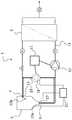
- FIG. 1shows schematically a filter system according to the invention.
- FIG. 1shows schematically a filter system 1 according to the invention.
- the filter systemcomprises a container 3 .
- the container 3can be a flexible, disposable bag, such as a hanging bag, for example a pillow formed bag.
- the container 3could also be another kind of flexible, disposable bag provided hanging or standing alone or provided inside a hard container.
- the container 3could even be a stainless steel container.
- the mixing method according to the inventionwill be suitable for all these alternatives of containers and flexibility will be improved and cost will be decreased because of the avoidance of impeller and magnetic drive. Furthermore, if weighing of the container is needed it is an advantage that the container is not in contact with a magnetic drive.
- the filter systemfurther comprises a filter 5 , which is connected to a recirculation inlet 7 of the container 3 and to a recirculation outlet 9 of the container by a recirculation flow path 11 .
- the filter 5is in this example a tangential flow filtration, TFF, filter which typically is provided in either flat sheet configurations or hollow-fibre configurations. Other configurations of TFF filters are feasible.
- the filter 5could also be another kind of device that requires a feed flow to be split into two fluid flows of different properties with one of the flows being redirected to the container, such as for example a hydrocyclone or other types of separation or processing devices. A combined requirement for all of mentioned filter types is that good mixing in the container needs to be maintained.
- a feed pump 12is provided in the recirculation flow path between the recirculation outlet 9 of the container and the filter 5 .
- the feed pumppumps content from the container through the recirculation flow path and via the filter.
- a mixing loop 13is provided in parallel with the recirculation loop 11 .
- the mixing loopis connected to a mixing inlet 15 of the container and to a mixing outlet 17 of the container.
- the mixing inlet 15 of the containercould be the same as the recirculation inlet 7 of the container and the mixing outlet 17 of the container could be the same as the recirculation outlet 9 of the container. They could also be separated. Furthermore parts of the recirculation flow path 11 can be the same as the mixing loop 13 .
- a mixing pump 19is provided in the mixing loop 13 . The mixing pump pumps content from the container 3 through the mixing loop 13 .
- the mixing pumpis in one embodiment of the invention a disposable pump, such as for example a centrifugal pump, a magnetically driven and coupled centrifugal mixing pump with a disposable head, a diaphragm pump, a lobe pump or a peristaltic pump.
- the mixing loop 13can in one embodiment of the invention be provided as an optional module that can be connected if there is a need for it. In this case the mixing loop 13 can be provided with aseptic connectors for easy and aseptic connection to the system. Furthermore the mixing loop 13 can be provided with valves such that the mixing loop easily can be disconnected.
- the mixing pump 19 and the feed pump 12are connected (by wire or wirelessly) to a control system 21 of the filter system 1 .
- the control system 21is arranged to control the mixing pump 19 in dependence of the operational conditions of the feed pump 12 .
- the mixing pumpdoes not need to be turned on and contribute to the mixing in the container when the feed pump pumps content from the container at a flow rate above a predefined threshold rate. However, when the feed pump pumps content from the container at a flow rate below said predefined threshold rate the mixing pump should be controlled by the control system 21 to be switched on.
- the flow rate in the mixing loop 13can be controlled by controlling the mixing pump 19 from the control system 21 in dependence of the flow rate in the recirculation flow path 11 .
- the mixing pump 19can pump at different flow rates, while in another embodiment the mixing pump 19 can be operated at one flow rate and may be engaged in an intermittent fashion.
- the mixing pumpcan be controlled in dependence of sensors 23 a , 23 b provided in the system instead of or in complement to in dependence of the operation conditions of the feed pump.
- Sensorscan be provided inside the container and/or in the recirculation flow path and/or in the mixing loop.
- the sensorscould for example measure concentration, absorbance or viscosity and these measured values could be used for controlling the mixing pump.
- a control system 21 ′gathers data from the sensors 23 a , 23 b and controls the mixing pump 19 . If for example two sensors positioned in different locations in the container show different values the mixing pump could be started or its pumping flow rate and thereby the mixing intensity could be raised. Threshold values for the differences should suitably be set for the control of the mixing pump, i.e. the mixing pump is not started until there is a difference in measured values from two sensors above a threshold difference.
- the mixing pumpcan be controlled in dependence of one or more factors. This could be properties of content/fluids in the system and/or other types of conditions in the system.
- the properties of the content in the systemcan be fluid properties of fluids in any part of the system measured by for example different types of sensors. It can be content in the container or fluid/content in any of the fluid lines of the system, for example retentate or permeate flow or a separate flow into the container such as the addition of diafiltration buffer in a diafiltration operation or the addition of sample in a fed batch concentration.
- Conditions in the systemcan for example be amount of fluid flow in the system, operational performance of other pumps than the mixing pump in the system or the volume of the content in the container or the weight of content in the container or the weight of the whole container. Conditions in the system may also be calculated parameters such as volumetric information. Further, conditions in the system may be determined by time and/or elapsed time, the status of control systems, information derived from collected or evaluated data and user interactions. The skilled in the art will acknowledge that there are more examples. The mixing pump can be controlled in dependence of one or more of these different conditions or properties.
- the filter system according to this systemcan easily be adapted for single use/disposable.
- the container, the flow lines, the filter and the mixing loop with the mixing pumpare in one embodiment of the invention pre-sterilized.
- the mixing loop according to this inventioncould also be useful in other types of systems where no recirculation flow path is present.
- a separation or processing devicewhich does not require the feed flow to be split into two fluid flows but instead the fluid being rather quantitatively processed and directed into a single, processed, fluid flow downstream the filter and device, respectively.
- Such a filtercould be a normal flow filter (dead-end filter) or filter with adsorptive properties, such as for example membrane adsorbers.
- NFF filterstypically provide a solid liquid separation by removing particles
- membrane adsorbersprovide a separation of components in solution by for example ion exchange or affinity interactions between the components to be separated and the membrane adsorber.
- device formats and fluid flowscan be combined. Even in absence of a fluid flow returning to the container there is a need to ensure homogeneity in the container and to avoid for example sedimentation processes when processing cells, other particulates or fluids that tend to a separation into different fractions or phases without active mixing.
- the mixing loop of this inventioncan be useful also in these systems.
Landscapes
- Chemical & Material Sciences (AREA)
- Chemical Kinetics & Catalysis (AREA)
- Engineering & Computer Science (AREA)
- Water Supply & Treatment (AREA)
- Physics & Mathematics (AREA)
- Fluid Mechanics (AREA)
- External Artificial Organs (AREA)
- Accessories For Mixers (AREA)
Abstract
Description
Claims (10)
Applications Claiming Priority (3)
| Application Number | Priority Date | Filing Date | Title |
|---|---|---|---|
| IN3675DE2015 | 2015-11-10 | ||
| IN3675/DEL/2015 | 2015-11-10 | ||
| PCT/EP2016/076046WO2017080846A1 (en) | 2015-11-10 | 2016-10-28 | A mixing method and system |
Publications (2)
| Publication Number | Publication Date |
|---|---|
| US20180304199A1 US20180304199A1 (en) | 2018-10-25 |
| US10625210B2true US10625210B2 (en) | 2020-04-21 |
Family
ID=57226959
Family Applications (1)
| Application Number | Title | Priority Date | Filing Date |
|---|---|---|---|
| US15/769,461Active2037-01-28US10625210B2 (en) | 2015-11-10 | 2016-10-28 | Mixing method and system |
Country Status (4)
| Country | Link |
|---|---|
| US (1) | US10625210B2 (en) |
| EP (1) | EP3374071B1 (en) |
| CN (1) | CN108348875B (en) |
| WO (1) | WO2017080846A1 (en) |
Families Citing this family (1)
| Publication number | Priority date | Publication date | Assignee | Title |
|---|---|---|---|---|
| EP4268943A1 (en)* | 2022-04-27 | 2023-11-01 | Levitronix GmbH | A device for tangential flow filtration of a fluid |
Citations (9)
| Publication number | Priority date | Publication date | Assignee | Title |
|---|---|---|---|---|
| IT1121108B (en)* | 1979-05-15 | 1986-03-26 | Ricciotti Enrico | ELECTRONIC-ELECTROMECHANICAL SYSTEM FOR PILOTING ELECTRIC PUMPS IN LEVEL CONTROL IN WATER TANKS |
| US5277691A (en)* | 1992-01-13 | 1994-01-11 | Eastman Kodak Company | Vacuum degassing process |
| JP2006141185A (en)* | 2004-11-15 | 2006-06-01 | Nidec Shibaura Corp | Synchronous motor |
| WO2009148499A2 (en) | 2008-05-30 | 2009-12-10 | Millipore Corporation | Container having vortex breaker and a fluid diverter and system |
| US20100130761A1 (en)* | 2006-06-28 | 2010-05-27 | Due Miljø As | Deacidification Method |
| US20130029411A1 (en)* | 2011-07-29 | 2013-01-31 | General Electric Company | Systems, methods and control laws for cell harvesting |
| EP2623564A1 (en) | 2012-02-03 | 2013-08-07 | Omya International AG | Installation for the purification of minerals, pigments and/or fillers and/or the preparation of precipitated earth alkali carbonate |
| EP2641877A1 (en) | 2012-03-20 | 2013-09-25 | Veolia Water Solutions & Technologies Support | Method for treating a waste stream using a bioreactor and a membrane filter |
| WO2015157031A1 (en) | 2014-04-08 | 2015-10-15 | Oasys Water, Inc. | Osmotic separation systems and methods |
Family Cites Families (1)
| Publication number | Priority date | Publication date | Assignee | Title |
|---|---|---|---|---|
| EP2925428A4 (en) | 2012-11-29 | 2016-07-27 | Emd Millipore Corp | CONTAINER HAVING A MAGNETIC PROPELLER ASSEMBLY COMPRISING A HOOD |
- 2016
- 2016-10-28USUS15/769,461patent/US10625210B2/enactiveActive
- 2016-10-28EPEP16790556.1Apatent/EP3374071B1/enactiveActive
- 2016-10-28CNCN201680065557.0Apatent/CN108348875B/enactiveActive
- 2016-10-28WOPCT/EP2016/076046patent/WO2017080846A1/ennot_activeCeased
Patent Citations (9)
| Publication number | Priority date | Publication date | Assignee | Title |
|---|---|---|---|---|
| IT1121108B (en)* | 1979-05-15 | 1986-03-26 | Ricciotti Enrico | ELECTRONIC-ELECTROMECHANICAL SYSTEM FOR PILOTING ELECTRIC PUMPS IN LEVEL CONTROL IN WATER TANKS |
| US5277691A (en)* | 1992-01-13 | 1994-01-11 | Eastman Kodak Company | Vacuum degassing process |
| JP2006141185A (en)* | 2004-11-15 | 2006-06-01 | Nidec Shibaura Corp | Synchronous motor |
| US20100130761A1 (en)* | 2006-06-28 | 2010-05-27 | Due Miljø As | Deacidification Method |
| WO2009148499A2 (en) | 2008-05-30 | 2009-12-10 | Millipore Corporation | Container having vortex breaker and a fluid diverter and system |
| US20130029411A1 (en)* | 2011-07-29 | 2013-01-31 | General Electric Company | Systems, methods and control laws for cell harvesting |
| EP2623564A1 (en) | 2012-02-03 | 2013-08-07 | Omya International AG | Installation for the purification of minerals, pigments and/or fillers and/or the preparation of precipitated earth alkali carbonate |
| EP2641877A1 (en) | 2012-03-20 | 2013-09-25 | Veolia Water Solutions & Technologies Support | Method for treating a waste stream using a bioreactor and a membrane filter |
| WO2015157031A1 (en) | 2014-04-08 | 2015-10-15 | Oasys Water, Inc. | Osmotic separation systems and methods |
Non-Patent Citations (2)
| Title |
|---|
| PCT International Search Report for PCT Application No. PCT/EP2016/076046 dated Jan. 27, 2017 (10 pages). |
| Zhou et al., "Separation of Hyaluronic Acid From Fermentation Broth by Tangential Flow Microfiltration and Ultrafiltration," Separation and Purification Technology, 2006, 52:29-38. |
Also Published As
| Publication number | Publication date |
|---|---|
| EP3374071A1 (en) | 2018-09-19 |
| WO2017080846A1 (en) | 2017-05-18 |
| EP3374071B1 (en) | 2023-08-09 |
| CN108348875B (en) | 2021-07-16 |
| US20180304199A1 (en) | 2018-10-25 |
| CN108348875A (en) | 2018-07-31 |
Similar Documents
| Publication | Publication Date | Title |
|---|---|---|
| US10213742B2 (en) | Micro flow filtration system and flow filtration method | |
| US10463988B2 (en) | Single use slurrying and chromatography systems | |
| US12186706B2 (en) | Processing system for multiple tangential flow filtration stations in bioprocessing applications | |
| US10010831B2 (en) | Large volume disposable ultrafiltration systems and methods | |
| US20090277833A1 (en) | Tangential flow filtration system | |
| IL285529B2 (en) | Process control systems and methods for use with filters and filtration processes | |
| CN119633599A (en) | Recirculation loop in CFF/TFF single-use flow path | |
| JP2005505405A (en) | Automated fluid filtration system for performing separation processes and acquiring and recording data about them | |
| CN107023496A (en) | Centrifugal pump group | |
| US10625210B2 (en) | Mixing method and system | |
| JP5420450B2 (en) | Filtration device | |
| US20250019394A1 (en) | Method for producing active pharmaceutical ingredient of biopharmaceutical, system for producing active pharmaceutical ingredient of biopharmaceutical, and active pharmaceutical ingredient of biopharmaceutical | |
| Lüken et al. | Automated tangential-flow diafiltration device | |
| US12350625B2 (en) | Scalable tangential flow filtration method and retrofit kit | |
| US20220184558A1 (en) | Filtration apparatus | |
| US9821110B2 (en) | Systems and methods for minimizing loss of cellular components during apheresis | |
| US20250011708A1 (en) | Method for producing active pharmaceutical ingredient of biopharmaceutical, system for producing active pharmaceutical ingredient of biopharmaceutical, and active pharmaceutical ingredient of biopharmaceutical | |
| US20250011706A1 (en) | Method for producing active pharmaceutical ingredient of biopharmaceutical, system for producing active pharmaceutical ingredient of biopharmaceutical, and active pharmaceutical ingredient of biopharmaceutical | |
| WO2016007115A2 (en) | Reciprocating tangential flow filtration method and apparatus cassette |
Legal Events
| Date | Code | Title | Description |
|---|---|---|---|
| AS | Assignment | Owner name:GE HEALTHCARE BIO-SCIENCES AB, SWEDEN Free format text:ASSIGNMENT OF ASSIGNORS INTEREST;ASSIGNORS:GEBAUER, KLAUS;DODDAPADAM SRINIVASA RAGHAVACHAR, PARTHA SARATHY;G R, NARENDRA;AND OTHERS;SIGNING DATES FROM 20160405 TO 20160411;REEL/FRAME:045587/0720 | |
| FEPP | Fee payment procedure | Free format text:ENTITY STATUS SET TO UNDISCOUNTED (ORIGINAL EVENT CODE: BIG.); ENTITY STATUS OF PATENT OWNER: LARGE ENTITY | |
| STPP | Information on status: patent application and granting procedure in general | Free format text:DOCKETED NEW CASE - READY FOR EXAMINATION | |
| STPP | Information on status: patent application and granting procedure in general | Free format text:NON FINAL ACTION MAILED | |
| STPP | Information on status: patent application and granting procedure in general | Free format text:RESPONSE TO NON-FINAL OFFICE ACTION ENTERED AND FORWARDED TO EXAMINER | |
| STPP | Information on status: patent application and granting procedure in general | Free format text:NOTICE OF ALLOWANCE MAILED -- APPLICATION RECEIVED IN OFFICE OF PUBLICATIONS | |
| STCF | Information on status: patent grant | Free format text:PATENTED CASE | |
| AS | Assignment | Owner name:CYTIVA SWEDEN AB, SWEDEN Free format text:CHANGE OF NAME;ASSIGNOR:GE HEALTHCARE BIO-SCIENCES AB;REEL/FRAME:054262/0184 Effective date:20200612 | |
| MAFP | Maintenance fee payment | Free format text:PAYMENT OF MAINTENANCE FEE, 4TH YEAR, LARGE ENTITY (ORIGINAL EVENT CODE: M1551); ENTITY STATUS OF PATENT OWNER: LARGE ENTITY Year of fee payment:4 |