US10625072B2 - Electrical stimulation methods with optical observation and devices therefor - Google Patents
Electrical stimulation methods with optical observation and devices thereforDownload PDFInfo
- Publication number
- US10625072B2 US10625072B2US15/789,576US201715789576AUS10625072B2US 10625072 B2US10625072 B2US 10625072B2US 201715789576 AUS201715789576 AUS 201715789576AUS 10625072 B2US10625072 B2US 10625072B2
- Authority
- US
- United States
- Prior art keywords
- electrical stimulation
- light
- lead
- tissue
- control module
- Prior art date
- Legal status (The legal status is an assumption and is not a legal conclusion. Google has not performed a legal analysis and makes no representation as to the accuracy of the status listed.)
- Active, expires
Links
- 230000000638stimulationEffects0.000titleclaimsabstractdescription183
- 238000000034methodMethods0.000titleclaimsabstractdescription68
- 230000003287optical effectEffects0.000titledescription19
- 238000012544monitoring processMethods0.000claimsabstractdescription26
- 230000004936stimulating effectEffects0.000claimsabstractdescription14
- 230000001537neural effectEffects0.000claimsdescription27
- 238000004891communicationMethods0.000claimsdescription12
- 239000000523sampleSubstances0.000claimsdescription6
- 102000003983FlavoproteinsHuman genes0.000claimsdescription3
- 108010057573FlavoproteinsProteins0.000claimsdescription3
- 210000001519tissueAnatomy0.000description70
- 239000013307optical fiberSubstances0.000description19
- 230000000694effectsEffects0.000description12
- 230000004044responseEffects0.000description10
- 210000004556brainAnatomy0.000description9
- 238000004458analytical methodMethods0.000description5
- 238000004590computer programMethods0.000description4
- 239000004020conductorSubstances0.000description4
- 230000008878couplingEffects0.000description4
- 238000010168coupling processMethods0.000description4
- 238000005859coupling reactionMethods0.000description4
- 230000008569processEffects0.000description4
- 210000000278spinal cordAnatomy0.000description4
- 238000003860storageMethods0.000description3
- KDLHZDBZIXYQEI-UHFFFAOYSA-NPalladiumChemical compound[Pd]KDLHZDBZIXYQEI-UHFFFAOYSA-N0.000description2
- 239000004696Poly ether ether ketoneSubstances0.000description2
- 239000000560biocompatible materialSubstances0.000description2
- 230000005540biological transmissionEffects0.000description2
- 238000001444catalytic combustion detectionMethods0.000description2
- 210000004027cellAnatomy0.000description2
- 208000022371chronic pain syndromeDiseases0.000description2
- 208000037265diseases, disorders, signs and symptomsDiseases0.000description2
- 239000003814drugSubstances0.000description2
- 229940079593drugDrugs0.000description2
- 238000003780insertionMethods0.000description2
- 230000037431insertionEffects0.000description2
- 238000005259measurementMethods0.000description2
- 210000003205muscleAnatomy0.000description2
- 210000005036nerveAnatomy0.000description2
- 230000007383nerve stimulationEffects0.000description2
- 239000012811non-conductive materialSubstances0.000description2
- 230000000737periodic effectEffects0.000description2
- 210000000578peripheral nerveAnatomy0.000description2
- BASFCYQUMIYNBI-UHFFFAOYSA-NplatinumChemical compound[Pt]BASFCYQUMIYNBI-UHFFFAOYSA-N0.000description2
- 229920002530polyetherether ketonePolymers0.000description2
- 230000001225therapeutic effectEffects0.000description2
- 238000011282treatmentMethods0.000description2
- OKTJSMMVPCPJKN-UHFFFAOYSA-NCarbonChemical compound[C]OKTJSMMVPCPJKN-UHFFFAOYSA-N0.000description1
- 239000004593EpoxySubstances0.000description1
- 206010021639IncontinenceDiseases0.000description1
- 206010033799ParalysisDiseases0.000description1
- FAPWRFPIFSIZLT-UHFFFAOYSA-MSodium chlorideChemical compound[Na+].[Cl-]FAPWRFPIFSIZLT-UHFFFAOYSA-M0.000description1
- RTAQQCXQSZGOHL-UHFFFAOYSA-NTitaniumChemical compound[Ti]RTAQQCXQSZGOHL-UHFFFAOYSA-N0.000description1
- 230000002159abnormal effectEffects0.000description1
- 229910045601alloyInorganic materials0.000description1
- 239000000956alloySubstances0.000description1
- 230000008901benefitEffects0.000description1
- JUPQTSLXMOCDHR-UHFFFAOYSA-Nbenzene-1,4-diol;bis(4-fluorophenyl)methanoneChemical compoundOC1=CC=C(O)C=C1.C1=CC(F)=CC=C1C(=O)C1=CC=C(F)C=C1JUPQTSLXMOCDHR-UHFFFAOYSA-N0.000description1
- 239000003990capacitorSubstances0.000description1
- 229910052799carbonInorganic materials0.000description1
- 239000000969carrierSubstances0.000description1
- 238000005266castingMethods0.000description1
- 230000001413cellular effectEffects0.000description1
- 229920001940conductive polymerPolymers0.000description1
- 238000010586diagramMethods0.000description1
- 201000010099diseaseDiseases0.000description1
- 208000037765diseases and disordersDiseases0.000description1
- 208000035475disorderDiseases0.000description1
- 238000005516engineering processMethods0.000description1
- 239000000835fiberSubstances0.000description1
- 239000012530fluidSubstances0.000description1
- 239000000446fuelSubstances0.000description1
- 230000006870functionEffects0.000description1
- 238000002513implantationMethods0.000description1
- 230000001939inductive effectEffects0.000description1
- 238000001802infusionMethods0.000description1
- 238000001746injection mouldingMethods0.000description1
- 238000011835investigationMethods0.000description1
- 238000004519manufacturing processMethods0.000description1
- 239000000463materialSubstances0.000description1
- 230000004060metabolic processEffects0.000description1
- 229910052751metalInorganic materials0.000description1
- 239000002184metalSubstances0.000description1
- 150000002739metalsChemical class0.000description1
- 230000004048modificationEffects0.000description1
- 238000012986modificationMethods0.000description1
- 238000000465mouldingMethods0.000description1
- 210000001087myotubuleAnatomy0.000description1
- 210000004126nerve fiberAnatomy0.000description1
- 210000000056organAnatomy0.000description1
- 230000003204osmotic effectEffects0.000description1
- 229910052763palladiumInorganic materials0.000description1
- XSKIUFGOTYHDLC-UHFFFAOYSA-Npalladium rhodiumChemical compound[Rh].[Pd]XSKIUFGOTYHDLC-UHFFFAOYSA-N0.000description1
- 229910052697platinumInorganic materials0.000description1
- HWLDNSXPUQTBOD-UHFFFAOYSA-Nplatinum-iridium alloyChemical compound[Ir].[Pt]HWLDNSXPUQTBOD-UHFFFAOYSA-N0.000description1
- 229920001296polysiloxanePolymers0.000description1
- 229920002635polyurethanePolymers0.000description1
- 239000004814polyurethaneSubstances0.000description1
- 239000011780sodium chlorideSubstances0.000description1
- 208000020431spinal cord injuryDiseases0.000description1
- 210000003594spinal gangliaAnatomy0.000description1
- 230000008685targetingEffects0.000description1
- 238000002560therapeutic procedureMethods0.000description1
- 229910052719titaniumInorganic materials0.000description1
- 239000010936titaniumSubstances0.000description1
- 230000007384vagal nerve stimulationEffects0.000description1
Images


Classifications
- A—HUMAN NECESSITIES
- A61—MEDICAL OR VETERINARY SCIENCE; HYGIENE
- A61N—ELECTROTHERAPY; MAGNETOTHERAPY; RADIATION THERAPY; ULTRASOUND THERAPY
- A61N1/00—Electrotherapy; Circuits therefor
- A61N1/02—Details
- A61N1/04—Electrodes
- A61N1/05—Electrodes for implantation or insertion into the body, e.g. heart electrode
- A—HUMAN NECESSITIES
- A61—MEDICAL OR VETERINARY SCIENCE; HYGIENE
- A61B—DIAGNOSIS; SURGERY; IDENTIFICATION
- A61B5/00—Measuring for diagnostic purposes; Identification of persons
- A61B5/0059—Measuring for diagnostic purposes; Identification of persons using light, e.g. diagnosis by transillumination, diascopy, fluorescence
- A61B5/0071—Measuring for diagnostic purposes; Identification of persons using light, e.g. diagnosis by transillumination, diascopy, fluorescence by measuring fluorescence emission
- A—HUMAN NECESSITIES
- A61—MEDICAL OR VETERINARY SCIENCE; HYGIENE
- A61B—DIAGNOSIS; SURGERY; IDENTIFICATION
- A61B5/00—Measuring for diagnostic purposes; Identification of persons
- A61B5/0059—Measuring for diagnostic purposes; Identification of persons using light, e.g. diagnosis by transillumination, diascopy, fluorescence
- A61B5/0082—Measuring for diagnostic purposes; Identification of persons using light, e.g. diagnosis by transillumination, diascopy, fluorescence adapted for particular medical purposes
- A61B5/0084—Measuring for diagnostic purposes; Identification of persons using light, e.g. diagnosis by transillumination, diascopy, fluorescence adapted for particular medical purposes for introduction into the body, e.g. by catheters
- A—HUMAN NECESSITIES
- A61—MEDICAL OR VETERINARY SCIENCE; HYGIENE
- A61N—ELECTROTHERAPY; MAGNETOTHERAPY; RADIATION THERAPY; ULTRASOUND THERAPY
- A61N1/00—Electrotherapy; Circuits therefor
- A61N1/18—Applying electric currents by contact electrodes
- A61N1/32—Applying electric currents by contact electrodes alternating or intermittent currents
- A61N1/36—Applying electric currents by contact electrodes alternating or intermittent currents for stimulation
- A61N1/3605—Implantable neurostimulators for stimulating central or peripheral nerve system
- A61N1/36128—Control systems
- A61N1/36135—Control systems using physiological parameters
- A61N1/36139—Control systems using physiological parameters with automatic adjustment
- A61B5/04001—
- A—HUMAN NECESSITIES
- A61—MEDICAL OR VETERINARY SCIENCE; HYGIENE
- A61B—DIAGNOSIS; SURGERY; IDENTIFICATION
- A61B5/00—Measuring for diagnostic purposes; Identification of persons
- A61B5/24—Detecting, measuring or recording bioelectric or biomagnetic signals of the body or parts thereof
- A—HUMAN NECESSITIES
- A61—MEDICAL OR VETERINARY SCIENCE; HYGIENE
- A61N—ELECTROTHERAPY; MAGNETOTHERAPY; RADIATION THERAPY; ULTRASOUND THERAPY
- A61N1/00—Electrotherapy; Circuits therefor
- A61N1/18—Applying electric currents by contact electrodes
- A61N1/32—Applying electric currents by contact electrodes alternating or intermittent currents
- A61N1/36—Applying electric currents by contact electrodes alternating or intermittent currents for stimulation
- A61N1/372—Arrangements in connection with the implantation of stimulators
- A61N1/37211—Means for communicating with stimulators
- A61N1/37235—Aspects of the external programmer
Definitions
- the present inventionis directed to the area of implantable electrical stimulation systems and methods of making and using the systems.
- the present inventionis also directed to implantable electrical stimulation leads having optical elements that facilitate observation and measurement of the effects of electrical stimulation, as well as methods of making and using the leads and electrical stimulation systems.
- Implantable electrical stimulation systemshave proven therapeutic in a variety of diseases and disorders.
- spinal cord stimulation systemshave been used as a therapeutic modality for the treatment of chronic pain syndromes.
- Peripheral nerve stimulationhas been used to treat chronic pain syndrome and incontinence, with a number of other applications under investigation.
- Functional electrical stimulation systemshave been applied to restore some functionality to paralyzed extremities in spinal cord injury patients.
- Stimulation of the brainsuch as deep brain stimulation, can be used to treat a variety of diseases or disorders.
- a stimulatorcan include a control module (with a pulse generator), one or more leads, and an array of stimulator electrodes on each lead.
- the stimulator electrodesare in contact with or near the nerves, muscles, or other tissue to be stimulated.
- the pulse generator in the control modulegenerates electrical pulses that are delivered by the electrodes to body tissue.
- One embodimentis a method of monitoring electrical stimulation.
- the methodincludes electrically stimulating tissue of the patient using at least one electrode of an implanted electrical stimulation lead.
- a distal portion of the electrical stimulation leadis disposed adjacent to the tissue of the patient to be stimulated.
- the electrical stimulation leadincludes the at least one electrode and at least one light receiver disposed along the distal portion of the electrical stimulation lead.
- the methodalso includes receiving light from the tissue at the at least one light receiver of the lead.
- the methodfurther includes implanting the electrical stimulation lead. In at least some embodiments, the method further includes analyzing the received light to monitor the electrical stimulation of the tissue. In at least some embodiments, the method further includes modifying parameters for electrically stimulating the tissue based on the analyzing of the received light. In at least some embodiments, the analyzing and modifying are performed automatically by an implantable control module coupled to the lead.
- the methodfurther includes, prior to receiving light from the tissue, emitting light from the at least one light receiver to induce emission of the light from the tissue. In at least some embodiments, the method further includes, prior to receiving light from the tissue, emitting light from at least one light emitter disposed along the distal portion of the electrical stimulation lead to induce emission of the light from the tissue. In at least some embodiments, the received light from the tissue arises from autofluorescence of the tissue.
- Another embodimentis a system for monitoring electrical stimulation, the system including an electrical stimulation lead including at least one electrode and at least one light receiver disposed along the distal portion of the electrical stimulation lead.
- the systemalso including at least one processor configured to: direct electrical stimulation of tissue of a patient through the at least one electrode of the lead; and analyze light received by the at least one light receiver from the tissue to monitor the electrical stimulation of the tissue.
- the at least one processoris also configured to modify parameters for electrically stimulating the tissue based on the analyzing of the received light.
- the at least one processorcan also be configured to perform one or more of any other steps of the methods described above.
- the systemfurther includes a control module coupleable to the lead, wherein the at least one processor is disposed in the control module.
- the systemfurther includes a control module coupleable to the lead and a programming unit configured and arranged for communication with the control module, wherein the at least one processor includes a first processor disposed in the control module and a second processor disposed in the programming unit.
- Yet another embodimentis a method of monitoring electrical stimulation.
- the methodincludes electrically stimulating tissue of the patient using at least one electrode of an implanted electrical stimulation lead.
- a distal portion of the electrical stimulation leadis disposed adjacent to the tissue of the patient to be stimulated.
- the electrical stimulation leadincludes the at least one electrode and at least one light emitter disposed along the distal portion of the electrical stimulation lead.
- the methodalso includes emitting light from the at least one light emitter to induce emission of electrical signals from the tissue; receiving the electrical signals from the tissue at the at least one electrode of the lead; and analyzing the received electrical signals to monitor the electrical stimulation of the tissue.
- the methodfurther includes analyzing the received electrical signals to monitor the electrical stimulation of the tissue. In at least some embodiments, the method further includes modifying parameters for electrically stimulating the tissue based on the analyzing of the received electrical signals. In at least some embodiments, the method further includes implanting the electrical stimulation lead.
- a further embodimentis a system for monitoring electrical stimulation that includes an electrical stimulation lead including the at least one electrode and at least one light emitter disposed along the distal portion of the electrical stimulation lead.
- the systemalso includes at least one processor configured to: direct electrical stimulation of tissue of a patient through the at least one electrode of the lead; direct emission of light from the at least one light emitter to induce emission of electrical signals from the tissue; and analyze electrical signals received by the at least one electrode from the tissue is response to the emission of the light to monitor the electrical stimulation of the tissue.
- the at least one processoris also configured to modify parameters for electrically stimulating the tissue based on the analyzing of the electrical signals.
- the at least one processorcan also be configured to perform one or more of any other steps of the methods described above.
- the systemfurther includes a control module coupleable to the lead, wherein the at least one processor is disposed in the control module.
- the systemfurther includes a control module coupleable to the lead and a programming unit configured and arranged for communication with the control module, wherein the at least one processor includes a first processor disposed in the control module and a second processor disposed in the programming unit.
- Another embodimentis a non-transitory computer-readable medium having processor-executable instructions for monitoring electrical stimulation, the processor-executable instructions when installed onto a device enable the device to perform the any of the methods described above.
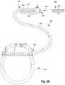
- FIG. 1Ais a schematic side view of one embodiment of an electrical stimulation system that includes a lead coupled to a control module, according to the invention
- FIG. 1Bis a schematic side view of another embodiment of an electrical stimulation system that includes a lead coupled to a control module, according to the invention
- FIG. 2Ais a schematic side view of one embodiment of the control module of FIGS. 1A and 1B configured and arranged to couple to an elongated device, according to the invention
- FIG. 2Bis a schematic side view of one embodiment of a lead extension configured and arranged to couple the elongated device of FIG. 2A to the control module of FIGS. 1A and 1B , according to the invention;
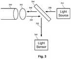
- FIG. 3is a schematic diagram of one embodiment of an optical arrangement for the electrical stimulation systems of FIGS. 1A and 1B , according to the invention
- FIG. 4Ais a schematic cross-sectional view of one embodiment of an electrical stimulation lead and a method of optically monitoring the electrical stimulation, according to the invention
- FIG. 4Bis a schematic cross-sectional view of one embodiment of an electrical stimulation lead and another method of optically monitoring the electrical stimulation, according to the invention
- FIG. 4Cis a schematic cross-sectional view of one embodiment of an electrical stimulation lead and a method of optically/electrically monitoring the electrical stimulation, according to the invention
- FIG. 4Dis a schematic cross-sectional view of one embodiment of an optical stimulation lead and a method of electrically monitoring the electrical stimulation, according to the invention.
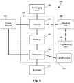
- FIG. 5is a schematic overview of one embodiment of components of a stimulation system, including an electronic subassembly disposed within a control module, according to the invention
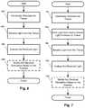
- FIG. 6is a flowchart of one method of monitoring electrical stimulation, according to the invention.
- FIG. 7is a flowchart of another method of monitoring electrical stimulation, according to the invention.
- FIG. 8is a flowchart of a third method of monitoring electrical stimulation, according to the invention.
- FIG. 9is a flowchart of one method of monitoring optical stimulation, according to the invention.
- the present inventionis directed to the area of implantable electrical stimulation systems and methods of making and using the systems.
- the present inventionis also directed to implantable electrical stimulation leads having optical elements that facilitate observation and measurement of the effects of electrical stimulation, as well as methods of making and using the leads and electrical stimulation systems.
- Suitable implantable electrical stimulation systemsinclude, but are not limited to, a least one lead with one or more electrodes disposed on a distal end of the lead and one or more terminals disposed on one or more proximal ends of the lead.
- Leadsinclude, for example, percutaneous leads, paddle leads, cuff leads, or any other arrangement of electrodes on a lead. Examples of electrical stimulation systems with leads are found in, for example, U.S. Pat. Nos.
- 2007/01500362009/0187222; 2009/0276021; 2010/0076535; 2010/0268298; 2011/0005069; 2011/0004267; 2011/0078900; 2011/0130817; 2011/0130818; 2011/0238129; 2011/0313500; 2012/0016378; 2012/0046710; 2012/0071949; 2012/0165911; 2012/0197375; 2012/0203316; 2012/0203320; 2012/0203321; 2012/0316615; 2013/0105071; and 2013/0197602, all of which are incorporated by reference.
- a percutaneous leadwill be exemplified, but it will be understood that the methods and systems described herein are also applicable to paddle leads and other leads.
- a percutaneous lead for electrical stimulation(for example, deep brain or spinal cord stimulation) includes stimulation electrodes that can be ring electrodes, segmented electrodes that extend only partially around the circumference of the lead, or any other type of electrode, or any combination thereof.
- the segmented electrodescan be provided in sets of electrodes, with each set having electrodes circumferentially distributed about the lead at a particular longitudinal position.
- the leadsare described herein relative to use for deep brain stimulation, but it will be understood that any of the leads can be used for applications other than deep brain stimulation, including spinal cord stimulation, peripheral nerve stimulation, dorsal root ganglia stimulation, vagal nerve stimulation, basoreceptor stimulation, or stimulation of other nerves, organs, or tissues.
- FIGS. 1A and 1Billustrate schematically two embodiments of an electrical stimulation system 100 .
- the electrical stimulation systemincludes a control module (e.g., a stimulator) 102 and a lead 103 coupleable to the control module 102 .
- the lead 103includes one or more lead bodies 106 .
- the lead 103is shown having a single lead body 106 .
- the leadincludes two lead bodies. It will be understood that the lead 103 can include any suitable number of lead bodies including, for example, one, two, three, four, five, six, seven, eight or more lead bodies 106 .
- the leadincludes one or more electrodes 134 disposed along the lead body 106 , and one or more terminals (e.g., 310 in FIG. 2A-2B ) disposed along each of the one or more lead bodies 106 and coupled to the electrodes 134 by conductors (not shown).
- the electrodes 134can be formed using any conductive, biocompatible material. Examples of suitable materials include metals, alloys, conductive polymers, conductive carbon, and the like, as well as combinations thereof.
- one or more of the electrodes 134are formed from one or more of: platinum, platinum iridium, palladium, palladium rhodium, or titanium.
- the number of electrodes 134may vary. For example, there can be one, two, four, six, eight, ten, twelve, fourteen, sixteen, or more electrodes 134 . As will be recognized, other numbers of electrodes 134 may also be used.
- the electrodes 134can be ring electrodes, tip electrodes, segmented electrodes, or any other suitable type of electrodes or any combination of these types of electrodes.
- Deep brain stimulation leads and other leadsmay include one or more sets of segmented electrodes. Segmented electrodes may provide for superior current steering than ring electrodes because target structures in deep brain stimulation are not typically symmetric about the axis of the distal electrode array. Instead, a target may be located on one side of a plane running through the axis of the lead.
- current steeringcan be performed not only along a length of the lead but also around a circumference of the lead. This provides precise three-dimensional targeting and delivery of the current stimulus to neural target tissue, while potentially avoiding stimulation of other tissue.
- Examples of leads with segmented electrodesinclude U.S. Patent Applications Publication Nos. 2010/0268298; 2011/0005069; 2011/0078900; 2011/0130803; 2011/0130816; 2011/0130817; 2011/0130818; 2011/0078900; 2011/0238129; 2011/0313500; 2012/0016378; 2012/0046710; 2012/0071949; 2012/0165911; 2012/197375; 2012/0203316; 2012/0203320; 2012/0203321; 2013/0197602; 2013/0261684; 2013/0325091; 2013/0317587; 2014/0039587; 2014/0353001; 2014/0358209; 2014/0358210; 2015/0018915; 2015/0021817; 2015/0045864; 2015/0021817; 2015/0066120; 2013/0197424; 2015/0151113; 2014/0358207; and U.S.
- the electrodes of the one or more lead bodies 106are typically disposed in, or separated by, a non-conductive, biocompatible material such as, for example, silicone, polyurethane, polyetheretherketone (“PEEK”), epoxy, and the like or combinations thereof.
- the lead bodies 106may be formed in the desired shape by any process including, for example, molding (including injection molding), casting, and the like.
- the non-conductive materialtypically extends from the distal end of the one or more lead bodies 106 to the proximal end of each of the one or more lead bodies 106 .
- At least one light receiver 135is provided at a distal end of the lead 103 , as illustrated in FIG. 1A .
- the light receiver 135is also a light emitter.
- the light receiver 135can be the end of an optical fiber that extends along the lead and is coupled to a light source (for example, light source 311 of FIG. 3 ) to deliver light from the light source for emission at the distal end of the lead by the light receiver 135 .
- the light receiver 135(in this case, the end of the optical fiber) can also receive light from the tissue and transmits the light along the lead to a light sensor (for example, light sensor 388 of FIG. 3 ).
- the light receiver 135only receives light and the lead does not include a light emitter.
- the light receiver 135can be an element, such as a photodiode, charged coupled device (CCD), or array of photodiodes or CCDs or the like, that receives light and converts the light into an electrical signal and the electrical signals are transmitted along the lead.
- a light receiver 135can be selected or tuned to receive light of only a certain wavelength or wavelength range or can be selected to receive light over a broad wavelength range or at multiple wavelengths/ranges.
- the lightcan be ultraviolet, visible, or infrared light or any range of wavelengths within these types of light.
- the number of light receivers 135 and the number of electrodes 134is equal with the light receivers and electrodes alternating, as illustrated in FIG. 1A .
- the number of light receivers 135 and number of electrodescan be different.
- each segmented electrodethere may be a light receiver for each segmented electrode (with the light receiver oriented in a same direction as the associated segmented electrode) or a single light receiver associated with each circumferential set of segmented electrodes or any other suitable arrangement of light receivers and electrodes.
- the light emittercan be a terminus of a light transmission element, such as an optical fiber, in which case the light source is distant from the distal end of the light (for example, in the control module or in a proximal portion of the lead or in a lead extension).
- the light emitter 136can be a light source, such as a light emitting diode (LED), laser diode, organic light emitting diode (OLED), or the like, and coupled to the electronic subassembly 110 of the control module to provide signals and power for operating the light source.
- LEDlight emitting diode
- OLEDorganic light emitting diode
- a light emittercan be selected or tuned to emit light of only a certain wavelength or wavelength range or can be selected to emit light over a broad range.
- the lightcan be ultraviolet, visible, or infrared light or any range of wavelengths within these types of light.
- the lead 103can be coupled to the control module 102 in any suitable manner.
- the leadis permanently attached to the control module 102 .
- the leadcan be coupled to the control module 102 by a connector (e.g., connector 144 of FIG. 2A ).
- the lead 103is shown coupling directly to the control module 102 through the connector 144 .
- the lead 103couples to the control module 102 via one or more intermediate devices, as illustrated in FIG. 2B .
- one or more lead extensions 324see e.g., FIG.
- the intermediate devicesmay be configured into any suitable arrangement.
- control module 102can include, for example, a connector housing 112 and a sealed electronics housing 114 .
- An electronic subassembly 110 and an optional power source 120are disposed in the electronics housing 114 .
- a control module connector 144is disposed in the connector housing 112 .
- the control module connector 144is configured and arranged to make an electrical connection between the lead 103 and the electronic subassembly 110 of the control module 102 .
- the control module 102also includes one or more light sources 111 disposed within the sealed electronics housing 114 .
- the one or more light sourcescan be, for example, a light emitting diode (LED), laser diode, organic light emitting diode (OLED), or the like.
- the control module 102includes multiple light sources, the light sources can provide light in at a same wavelength or wavelength band or some, or all, of the light sources can provide light at different wavelength or different wavelength bands.
- the control moduleincludes one or more light sources 111
- the light emitted by the light sourcescan be directed to an optical fiber (for example, optical fiber) or other light transmitting body for delivery to the light receiver 135 .
- the optical fibercan transmit the light from the one or more light sources 111 through the control module 102 and lead 103 to the light receiver 135 (which can be terminus of the optical fiber).
- the optical fiberis a single mode optical fiber.
- the optical fiberis a multi-mode optical fiber.
- the systemincludes a single optical fiber. In other embodiments, the system may employ multiple optical fibers in series or in parallel.
- FIG. 3illustrates one example of an optical system for producing and detecting light that can be present within the control module ( 102 in FIG. 1 ) or elsewhere in the system.
- the optical systemincludes a light source 311 , an optical fiber 380 , a lens 382 , a beamsplitter 384 , and a light sensor 388 .
- the light source 311produces light that is directed to the optical fiber 380 through the lens 382 and into the optical fiber 380 .
- the optical fiber 380is coupled to the lead and a light emitter or light receiver at the end of the lead. When light is received by the light receiver of the lead, that light 392 is transmitted through the lead to the optical fiber 380 .
- any suitable light sensorcan be used including a photodiode, CCD, or an array of photodiodes or CCDs. It will be recognized that other optical arrangements and systems with the same or different components can be used in the control module or elsewhere in the system.
- the stimulation system or components of the stimulation systemare typically implanted into the body of a patient.
- the stimulation systemcan be used for a variety of applications including, but not limited to brain stimulation, deep brain stimulation, neural stimulation, spinal cord stimulation, muscle stimulation, and the like.
- one or more terminalsare typically disposed along the proximal end of the one or more lead bodies 106 of the stimulation system 100 (as well as any splitters, lead extensions, adaptors, or the like) for electrical connection to corresponding connector contacts (e.g., 314 in FIGS. 2A-2B ).
- the connector contactsare disposed in connectors (e.g., 144 in FIGS. 1-2B ; and 322 FIG. 2B ) which, in turn, are disposed on, for example, the control module 102 (or a lead extension, a splitter, an adapter, or the like).
- Electrically conductive wires, cables, or the likeextend from the terminals to the light receiver 135 or optional one or more electrodes 134 .
- the electrically conductive wiresmay be embedded in the non-conductive material of the lead body 106 or can be disposed in one or more lumens (not shown) extending along the lead body 106 . In some embodiments, there is an individual lumen for each conductor. In other embodiments, two or more conductors extend through a lumen. There may also be one or more lumens (not shown) that open at, or near, the proximal end of the one or more lead bodies 106 , for example, for inserting a stylet to facilitate placement of the one or more lead bodies 106 within a body of a patient.
- the one or more lumensmay be flushed continually, or on a regular basis, with saline, epidural fluid, or the like.
- the one or more lumensare permanently or removably sealable at the distal end.
- FIG. 2Ais a schematic side view of one embodiment of a proximal end of one or more elongated devices 300 configured and arranged for coupling to one embodiment of the control module connector 144 .
- the one or more elongated devicesmay include, for example, one or more of the lead bodies 106 of FIGS. 1A and 1B , one or more intermediate devices (e.g., a splitter, the lead extension 324 of FIG. 2B , an adapter, or the like or combinations thereof), or a combination thereof.
- the control module connector 144defines at least one port into which a proximal end of the elongated device 300 can be inserted, as shown by directional arrows 312 a and 312 b .
- the connector housing 112is shown having two ports 304 a and 304 b .
- the connector housing 112can define any suitable number of ports including, for example, one, two, three, four, five, six, seven, eight, or more ports.
- the control module connector 144also includes a plurality of connector contacts, such as connector contact 314 , disposed within each port 304 a and 304 b .
- the connector contacts 314can be aligned with a plurality of terminals 310 disposed along the proximal end(s) of the elongated device(s) 300 to electrically couple the control module 102 to the electrodes ( 134 of FIG. 1 ) disposed on the paddle body 104 of the lead 103 .
- Each of the terminals 310can couple to the light receiver 135 or one or more of the optional electrodes 134 . Examples of connectors in control modules are found in, for example, U.S. Pat. Nos. 7,244,150 and 8,224,450, which are incorporated by reference.
- FIG. 2Bis a schematic side view of another embodiment of the stimulation system 100 .
- the stimulation system 100includes a lead extension 324 that is configured and arranged to couple one or more elongated devices 300 (e.g., one of the lead bodies 106 of FIG. 1 , a splitter, an adapter, another lead extension, or the like or combinations thereof) to the control module 102 .
- the lead extension 324is shown coupled to a single port 304 defined in the control module connector 144 .
- the lead extension 324is shown configured and arranged to couple to a single elongated device 300 .
- the lead extension 324is configured and arranged to couple to multiple ports 304 defined in the control module connector 144 (e.g., the ports 304 a and 304 b of FIG. 1 ), or to receive multiple elongated devices 300 (e.g., both of the lead bodies 106 of FIG. 1 ), or both.
- a lead extension connector 322is disposed on the lead extension 324 .
- the lead extension connector 322is shown disposed at a distal end 326 of the lead extension 324 .
- the lead extension connector 322includes a connector housing 328 .
- the connector housing 328defines at least one port 330 into which terminals 310 of the elongated device 300 can be inserted, as shown by directional arrow 338 .
- Each of the terminals 310can couple to the light receiver 135 or one or more of the optional electrodes 134 .
- the connector housing 328also includes a plurality of connector contacts, such as connector contact 340 .
- the connector contacts 340 disposed in the connector housing 328can be aligned with the terminals 310 of the elongated device 300 to electrically couple the lead extension 324 to the electrodes ( 134 of FIG. 1 ) disposed along the lead ( 103 in FIG. 1 ).
- the proximal end of the lead extension 324is similarly configured and arranged as a proximal end of the lead 103 (or other elongated device 300 ).
- the lead extension 324may include a plurality of electrically conductive wires (not shown) that electrically couple the connector contacts 340 to a proximal end 348 of the lead extension 324 that is opposite to the distal end 326 .
- the conductive wires disposed in the lead extension 324can be electrically coupled to a plurality of terminals (not shown) disposed along the proximal end 348 of the lead extension 324 .
- the proximal end 348 of the lead extension 324is configured and arranged for insertion into a connector disposed in another lead extension (or another intermediate device). In other embodiments (and as shown in FIG. 2B ), the proximal end 348 of the lead extension 324 is configured and arranged for insertion into the control module connector 144 .
- FIGS. 4A-4Cillustrate examples of different methods of observation of the effects of electrical stimulation.
- FIGS. 4A-4Cillustrate a lead 403 with a lead body 406 , one or more electrodes 434 , and at least one light receiver 435 .
- the light receiver 435may also act as a light emitter in some embodiments or that the lead 403 may include a separate light emitter.
- the light receiveris arranged to receive light generated by tissue as part of the function of the tissue or in response to electrical stimulation or any combination thereof.
- tissueFor example, at least some neural tissues, or molecules or components within the neural tissues, produce autofluorescence during normal or abnormal functioning, for example, as a consequence of changes in metabolism.
- autofluorescing molecules or other tissue componentsinclude, but are not limited to, NAD(P)H and flavoprotein.
- the light receivercan receive the light from this autofluorescence and convey that light (or electrical signals generated in the light receiver by that light) to the control module for monitoring or analysis.
- FIG. 4Aillustrates one embodiment in which electrical stimulation 452 is provided through one or more of the electrodes 452 of the lead 403 .
- light 456is generated and received by the at least one light receiver 435 .
- the light 456may also be generated prior to stimulation and the arrangement monitors or measures changes in the light such as, for example, changes in intensity, frequency, or the like.
- the received light 456can be used to monitor, observe, or measure the results of electrical stimulation 452 .
- FIG. 6illustrates one embodiment of steps of method for monitoring electrical stimulation.
- the tissueis electrically stimulated by the electrodes of the lead.
- lightis received from the tissue by the light receiver.
- the received lightis analyzed.
- parameters of the electrical stimulationare modified based on the analysis of the received light.
- lightmay be emitted by the light receiver or light emitter and an optical response to the emitted light by the tissue may be observed using the light receiver.
- lightmay be utilized to induce fluorescence or produce second or higher order harmonic emissions or otherwise cause the emission of light by neural tissue (or molecules or other components within in the neural tissue.)
- the emitted lightcan be used to probe the neural tissue before, during, or after stimulation and used to measure or monitor the effects of stimulation.
- FIG. 4Billustrates one embodiment in which electrical stimulation 452 is provided through one or more of the electrodes 452 .
- Light 454is emitted by the light receiver 435 (or a separate light emitter) to probe the tissue.
- light 456is generated by the tissue and received by the at least one light receiver 435 .
- the light 456may also be generated by the tissue prior to electrical stimulation (and, optionally, after emission of light 454 from the lead) and the arrangement monitors or measures changes in the light 456 such as, for example, changes in intensity, frequency, or the like.
- the received light 456can be used to monitor, observe, or measure the results of electrical stimulation 452 .
- FIG. 7illustrates one embodiment of steps of method for monitoring electrical stimulation.
- the tissueis electrically stimulated by the electrodes of the lead.
- lightis emitted from the lead to induce light emission by the tissue.
- step 706light is received from the tissue by the light receiver.
- step 708the received light is analyzed.
- steps 702 - 706can be performed simultaneously to simultaneously stimulate and illuminate the tissue to detect fluorescence changes.
- lightmay be emitted by the light receiver or light emitter and an electrical response by tissue to the emitted light may be obtained using one or more of the electrodes.
- lightmay be utilized to induce an electrical response in neural tissue (or molecules or other components within in the neural tissue.)
- the emitted lightcan be used to probe the neural tissue before, during, or after stimulation and used to measure or monitor the effects of stimulation.
- FIG. 4Cillustrates one embodiment in which electrical stimulation 452 is provided through one or more of the electrodes 452 .
- Light 454is emitted by the light receiver 435 (or a separate light emitter) to probe the tissue.
- electrical signals 458are generated by the tissue and received by one or more of the electrodes 434 .
- the electrical signals 458may also be generated by tissue prior to electrical stimulation (and, optionally, after emission of light 454 from the lead) and the arrangement monitors or measures changes in the electrical signals 458 such as, for example, changes in intensity, frequency, or the like.
- the light-induced electrical signal 458can be used to monitor, observe, or measure the results of electrical stimulation 452 .
- FIG. 8illustrates one embodiment of steps of method for monitoring electrical stimulation.
- the tissueis electrically stimulated by the electrodes of the lead.
- lightis emitted from the lead to induce electrical signals from the tissue.
- electrical signalsare received from the tissue by the one or more electrodes.
- the received electrical signalsare analyzed.
- parameters of the electrical stimulationare modified based on the analysis of the received electrical signals.
- FIG. 4Dillustrates an example of electrical observation of the effects of optical stimulation.
- Light 454is emitted by the light emitter 436 to stimulate the tissue.
- electrical signals 458are generated by the tissue and received by one or more of the electrodes 434 .
- the electrical signals 458may also be generated by tissue prior to optical stimulation and the arrangement monitors or measures changes in the electrical signals 458 such as, for example, changes in intensity, frequency, or the like.
- FIG. 9illustrates one embodiment of steps of method for monitoring electrical stimulation.
- the tissueis optically stimulated by the lead.
- electrical signalsare received from the tissue by the one or more electrodes.
- the received electrical signalsare analyzed.
- parameters of the electrical stimulationare modified based on the analysis of the received electrical signals.
- the observation of electrical or optical stimulation described above with respect to FIGS. 4A-4D and 6-9may be user-controlled or user-directed. For example, such observation may only be performed if directed by the user, such as a clinician, patient, programmer, or other individual.
- the observationmay be automatic, without user direction or control, or may be automatic in response to a user direction to initiate automatic observation.
- the observationmay be continuous, periodic, or performed at random times or intervals, or any combination thereof.
- the observed light or electrical signalsare provided to sensor (for example, light sensor 388 in FIG. 3 or another optical or electrical sensor) and the data generated by the sensor can be stored or evaluated on the control module.
- the sensor datamay be transmitted or otherwise delivered to an external device, such as a programming device (for example, programming unit 508 of FIG. 5 ).
- a usermay be allowed to observe the sensor data and alter stimulation parameters.
- the data generated by the sensormay be observed or evaluated by the control module (or an external device) and used to automatically modify one or more stimulation parameters.
- the observation of the effects of the electrical or optical stimulationcan act in a closed-loop feedback system, including at least the lead and control module, to monitor and modify the stimulation based on the observed effect.
- the observation of the effect of stimulationmay also be used to facilitate placement of the lead.
- the leadmay be positioned in tissue, the tissue is then stimulated, and the observation of the stimulation, as described above, can facilitate whether the position of the lead is acceptable or whether the lead should be repositioned.
- FIG. 5is a schematic overview of one embodiment of components of an electrical stimulation system 500 including an electronic subassembly 510 disposed within a control module. It will be understood that the electrical stimulation system can include more, fewer, or different components and can have a variety of different configurations including those configurations disclosed in the stimulator references cited herein.
- a power source 512can be used including, for example, a battery such as a primary battery or a rechargeable battery.
- a batterysuch as a primary battery or a rechargeable battery.
- other power sourcesinclude super capacitors, nuclear or atomic batteries, mechanical resonators, infrared collectors, thermally-powered energy sources, flexural powered energy sources, bioenergy power sources, fuel cells, bioelectric cells, osmotic pressure pumps, and the like including the power sources described in U.S. Pat. No. 5,437,193, incorporated herein by reference.
- powercan be supplied by an external power source through inductive coupling via the optional antenna 518 or a secondary antenna.
- the external power sourcecan be in a device that is mounted on the skin of the user or in a unit that is provided near the user on a permanent or periodic basis.
- the batterymay be recharged using the optional antenna 518 , if desired. Power can be provided to the battery for recharging by inductively coupling the battery through the antenna to a recharging unit 516 external to the user. Examples of such arrangements can be found in the references identified above.
- electrical signalsare delivered through the electrodes 134 of the lead body to stimulate nerve fibers, muscle fibers, or other body tissues near the electrical stimulation system.
- Light from the tissuecan be received by the light receiver 135 and delivered to the processor 504 .
- the processor 504is generally included to control the timing and other characteristics of the electrical stimulation system.
- the processor 504can, if desired, control one or more of the timing, pulse frequency, strength, duration, and waveform of the electrical stimulation.
- the processor 504selects which of the electrode(s) are cathodes and which electrode(s) are anodes.
- the processor 504may receive and evaluate or store signals from the light receiver or a sensor coupled to the light receiver, if desired.
- Any processorcan be used and can be as simple as an electronic device that, for example, produces electrical stimulation at a regular interval or the processor can be capable of receiving and interpreting instructions from an external programming unit 508 that, for example, allows modification of stimulation characteristics.
- the processor 504is coupled to a receiver 502 which, in turn, is coupled to the optional antenna 518 . This allows the processor 504 to receive instructions from an external source to, for example, direct the stimulation characteristics and the selection of electrodes, if desired.
- the antenna 518is capable of receiving signals (e.g., RF signals) from an external telemetry unit 506 which is programmed by the programming unit 508 .
- the programming unit 508can be external to, or part of, the telemetry unit 506 .
- the telemetry unit 506can be a device that is worn on the skin of the user or can be carried by the user and can have a form similar to a pager, cellular phone, or remote control, if desired.
- the telemetry unit 506may not be worn or carried by the user but may only be available at a home station or at a clinician's office.
- the programming unit 508can be any unit that can provide information to the telemetry unit 506 for transmission to the electrical stimulation system 500 .
- the programming unit 508can be part of the telemetry unit 506 or can provide signals or information to the telemetry unit 506 via a wireless or wired connection.
- One example of a suitable programming unitis a computer operated by the user or clinician to send signals to the telemetry unit 506 .
- the signals sent to the processor 504 via the antenna 518 and the receiver 502can be used to modify or otherwise direct the operation of the electrical stimulation system.
- the signalsmay be used to modify the stimulation characteristics of the electrical stimulation system such as modifying one or more of stimulation duration, pulse frequency, waveform, and stimulation amplitude.
- the signalsmay also direct the electrical stimulation system 500 to cease operation, to start operation, to start charging the battery, or to stop charging the battery.
- the stimulation systemdoes not include the antenna 518 or receiver 502 and the processor 504 operates as programmed.
- the electrical stimulation system 500may include a transmitter (not shown) coupled to the processor 504 and the antenna 518 for transmitting signals back to the telemetry unit 506 or another unit capable of receiving the signals.
- the electrical stimulation system 500may transmit signals indicating whether the electrical stimulation system 500 is operating properly or not or indicating when the battery needs to be charged or the level of charge remaining in the battery.
- the processor 504may also be capable of transmitting information about the stimulation characteristics so that a user or clinician can determine or verify the characteristics.
- the methods of monitoring electrical or optical stimulationcan be performed fully or at least partially with the processor 504 of the control module. Additionally or alternatively, some or all of the steps may be performed using a processor external to the control module such as, for example, a processor in the programming unit 508 .
- Systems referenced hereintypically include memory and typically include methods for communication with other devices including mobile devices.
- Methods of communicationcan include both wired and wireless (e.g., RF, optical, or infrared) communications methods and such methods provide another type of computer readable media; namely communication media.
- Wired communicationcan include communication over a twisted pair, coaxial cable, fiber optics, wave guides, or the like, or any combination thereof.
- Wireless communicationcan include RF, infrared, acoustic, near field communication, BluetoothTM, or the like, or any combination thereof.
- the computer program instructionscan be stored on any suitable computer-readable medium including, but not limited to, RAM, ROM, EEPROM, flash memory or other memory technology, CD-ROM, digital versatile disks (“DVD”) or other optical storage, magnetic cassettes, magnetic tape, magnetic disk storage or other magnetic storage devices, or any other medium which can be used to store the desired information and which can be accessed by a computer.
Landscapes
- Health & Medical Sciences (AREA)
- Life Sciences & Earth Sciences (AREA)
- Public Health (AREA)
- Engineering & Computer Science (AREA)
- Biomedical Technology (AREA)
- Veterinary Medicine (AREA)
- Animal Behavior & Ethology (AREA)
- General Health & Medical Sciences (AREA)
- Heart & Thoracic Surgery (AREA)
- Biophysics (AREA)
- Nuclear Medicine, Radiotherapy & Molecular Imaging (AREA)
- Radiology & Medical Imaging (AREA)
- Physics & Mathematics (AREA)
- Pathology (AREA)
- Medical Informatics (AREA)
- Molecular Biology (AREA)
- Surgery (AREA)
- Cardiology (AREA)
- Physiology (AREA)
- Neurology (AREA)
- Neurosurgery (AREA)
- Electrotherapy Devices (AREA)
Abstract
Description
Claims (20)
Priority Applications (1)
| Application Number | Priority Date | Filing Date | Title |
|---|---|---|---|
| US15/789,576US10625072B2 (en) | 2016-10-21 | 2017-10-20 | Electrical stimulation methods with optical observation and devices therefor |
Applications Claiming Priority (2)
| Application Number | Priority Date | Filing Date | Title |
|---|---|---|---|
| US201662411203P | 2016-10-21 | 2016-10-21 | |
| US15/789,576US10625072B2 (en) | 2016-10-21 | 2017-10-20 | Electrical stimulation methods with optical observation and devices therefor |
Publications (2)
| Publication Number | Publication Date |
|---|---|
| US20180110971A1 US20180110971A1 (en) | 2018-04-26 |
| US10625072B2true US10625072B2 (en) | 2020-04-21 |
Family
ID=61971193
Family Applications (1)
| Application Number | Title | Priority Date | Filing Date |
|---|---|---|---|
| US15/789,576Active2038-07-19US10625072B2 (en) | 2016-10-21 | 2017-10-20 | Electrical stimulation methods with optical observation and devices therefor |
Country Status (1)
| Country | Link |
|---|---|
| US (1) | US10625072B2 (en) |
Cited By (11)
| Publication number | Priority date | Publication date | Assignee | Title |
|---|---|---|---|---|
| WO2024136949A1 (en) | 2022-12-20 | 2024-06-27 | Boston Scientific Neuromodulation Corporation | Optical modulation cuff devices, systems, and methods of making and using |
| EP4398258A2 (en) | 2023-01-04 | 2024-07-10 | Boston Scientific Neuromodulation Corporation | Systems and methods incorporating a light therapy user interface for optical modulation |
| WO2024197009A1 (en) | 2023-03-22 | 2024-09-26 | Boston Scientific Neuromodulation Corporation | Systems for moving stimulation using anatomical directional controls |
| WO2024226642A2 (en) | 2023-04-28 | 2024-10-31 | Boston Scientific Neuromodulation Corporation | Systems and methods for modifying stimulation in response to a change in a symptom, therapeutic effect, or side effect |
| WO2025010358A1 (en) | 2023-07-06 | 2025-01-09 | Boston Scientific Neuromodulation Corporation | Systems and methods for selecting electrodes and providing stimulation |
| US12208268B2 (en) | 2014-10-07 | 2025-01-28 | Boston Scientific Neuromodulation Corporation | Systems, devices, and methods for electrical stimulation using feedback to adjust stimulation parameters |
| WO2025038353A2 (en) | 2023-08-11 | 2025-02-20 | Boston Scientific Neuromodulation Corporation | Methods and systems for control and modification of stimulation |
| US12357792B2 (en) | 2019-01-04 | 2025-07-15 | Shifamed Holdings, Llc | Internal recharging systems and methods of use |
| US12403313B2 (en) | 2021-06-15 | 2025-09-02 | Boston Scientific Neuromodulation Corporation | Methods and systems for estimating neural activation by stimulation using a stimulation system |
| US12403315B2 (en) | 2021-04-27 | 2025-09-02 | Boston Scientific Neuromodulation Corporation | Systems and methods for automated programming of electrical stimulation |
| US12440656B2 (en) | 2021-04-23 | 2025-10-14 | Shifamed Holdings, Llc | Power management for interatrial shunts and associated systems and methods |
Families Citing this family (19)
| Publication number | Priority date | Publication date | Assignee | Title |
|---|---|---|---|---|
| US10335607B2 (en) | 2016-02-05 | 2019-07-02 | Boston Scientific Neuromodulation Corporation | Implantable optical stimulation lead and methods of making and using |
| CN109069007A (en) | 2016-03-08 | 2018-12-21 | 泽博拉医疗科技公司 | Non-invasive detection of skin diseases |
| EP3614915A4 (en)* | 2017-04-28 | 2021-01-20 | Enspectra Health, Inc. | Systems and methods for imaging and measurement of sarcomeres |
| WO2019005689A1 (en) | 2017-06-26 | 2019-01-03 | Boston Scientific Neuromodulation Corporation | SYSTEMS AND METHODS FOR VISUALIZING AND CONTROLLING OPTOGENETIC STIMULATION USING OPTICAL STIMULATION SYSTEMS |
| EP3737464A1 (en) | 2018-01-11 | 2020-11-18 | Boston Scientific Neuromodulation Corporation | Methods and systems for stimulation for glial modulation |
| EP3768372A1 (en) | 2018-03-23 | 2021-01-27 | Boston Scientific Neuromodulation Corporation | An optical stimulation system with on-demand monitoring and methods of making and using |
| WO2019183054A1 (en) | 2018-03-23 | 2019-09-26 | Boston Scientific Neuromodulation Corporation | Optical stimulation systems with calibration and methods of making and using |
| US11224743B2 (en) | 2018-09-21 | 2022-01-18 | Boston Scientific Neuromodulation Corporation | Systems and methods for making and using modular leads for electrical stimulation systems |
| CN113473900B (en) | 2018-11-13 | 2024-09-24 | 恩斯派克特拉健康公司 | Method and system for generating depth profiles |
| WO2020102039A1 (en) | 2018-11-16 | 2020-05-22 | Boston Scientific Neuromodulation Corporation | An optical stimulation system with on-demand monitoring and methods of making |
| WO2021003496A1 (en)* | 2019-07-01 | 2021-01-07 | Wavegate Corporation | Improved surgical electrode and lead for use with implanted pulse generator and method of use |
| US12226626B2 (en) | 2019-07-01 | 2025-02-18 | Wavegate Corporation | Electrode and percutaneous lead and method of use |
| US11806547B2 (en) | 2020-09-04 | 2023-11-07 | Boston Scientific Neuromodulation Corporation | Stimulation systems with a lens arrangement for light coupling and methods of making and using |
| US12402004B2 (en) | 2020-11-04 | 2025-08-26 | Boston Scient ation Corporation | Methods and systems for managing access to implantable medical devices |
| EP4196208A1 (en) | 2020-11-11 | 2023-06-21 | Boston Scientific Neuromodulation Corporation | Voice command handler for programming stimulation systems and methods of using |
| JP7688170B2 (en) | 2021-02-25 | 2025-06-03 | ボストン サイエンティフィック ニューロモデュレイション コーポレイション | Method and system for deep brain stimulation of the nucleus basalis of meynert |
| WO2022216844A1 (en)* | 2021-04-08 | 2022-10-13 | Boston Scientific Neuromodulation Corporation | Photobiomodulation system and delivery device |
| WO2022261001A1 (en) | 2021-06-07 | 2022-12-15 | Boston Scientific Neuromodulation Corporation | Stimulation systems with user-specified routines and methods of making and using |
| CN113440143B (en)* | 2021-07-12 | 2025-07-25 | 北京华科恒生医疗科技有限公司 | Fluorescent sensing composite deep electrode |
Citations (135)
| Publication number | Priority date | Publication date | Assignee | Title |
|---|---|---|---|---|
| US5076270A (en) | 1990-05-03 | 1991-12-31 | Siemens-Pacesetter, Inc. | Apparatus and method for making electrical connections in an implantable pacemaker |
| US5437193A (en) | 1994-03-22 | 1995-08-01 | The United States Of America As Represented By The United States Department Of Energy | Method and apparatus for testing microfilaments |
| US5445608A (en) | 1993-08-16 | 1995-08-29 | James C. Chen | Method and apparatus for providing light-activated therapy |
| US5556421A (en) | 1995-02-22 | 1996-09-17 | Intermedics, Inc. | Implantable medical device with enclosed physiological parameter sensors or telemetry link |
| US6175710B1 (en) | 1991-07-06 | 2001-01-16 | Fujitsu Limited | Electrophotographic recording apparatus using developing device with one-component type developer and having combination of charge injection effect and conductive contact type charger |
| US6181969B1 (en) | 1998-06-26 | 2001-01-30 | Advanced Bionics Corporation | Programmable current output stimulus stage for implantable device |
| US6224450B1 (en) | 1998-08-28 | 2001-05-01 | Laurie J. Norton | Cycling activity belt |
| US6271094B1 (en) | 2000-02-14 | 2001-08-07 | International Business Machines Corporation | Method of making MOSFET with high dielectric constant gate insulator and minimum overlap capacitance |
| US6295944B1 (en) | 2000-06-20 | 2001-10-02 | J Timothy Lovett | Automatic tethering system for a floating dock |
| US6364276B1 (en) | 1997-07-12 | 2002-04-02 | Deirdre Polzin | Fountain, kit, bracket and method of assembly |
| US6391985B1 (en) | 1999-10-21 | 2002-05-21 | Union Carbide Chemicals & Plastics Technology Corporation | High condensing mode polyolefin production under turbulent conditions in a fluidized bed |
| US20020156513A1 (en) | 2000-08-17 | 2002-10-24 | Borkan William N. | Spinal cord stimulation leads |
| US20020161417A1 (en) | 2000-08-09 | 2002-10-31 | Dean Scribner | Microelectronic stimulator array for stimulating nerve tissue |
| US6516227B1 (en) | 1999-07-27 | 2003-02-04 | Advanced Bionics Corporation | Rechargeable spinal cord stimulator system |
| US6609029B1 (en) | 2000-02-04 | 2003-08-19 | Advanced Bionics Corporation | Clip lock mechanism for retaining lead |
| US6609032B1 (en) | 1999-01-07 | 2003-08-19 | Advanced Bionics Corporation | Fitting process for a neural stimulation system |
| US6741892B1 (en) | 2000-03-10 | 2004-05-25 | Advanced Bionics Corporation | Movable contact locking mechanism for spinal cord stimulator lead connector |
| US20050216072A1 (en) | 2000-08-16 | 2005-09-29 | Vanderbilt University | System and methods for optical stimulation of neural tissues |
| US6988001B2 (en) | 2001-10-31 | 2006-01-17 | Biophan Technologies, Inc. | Hermetic component housing for photonic catheter |
| US6993384B2 (en) | 2001-12-04 | 2006-01-31 | Advanced Bionics Corporation | Apparatus and method for determining the relative position and orientation of neurostimulation leads |
| US20060155348A1 (en) | 2004-11-15 | 2006-07-13 | Decharms Richard C | Applications of the stimulation of neural tissue using light |
| US20060161227A1 (en) | 2004-11-12 | 2006-07-20 | Northwestern University | Apparatus and methods for optical stimulation of the auditory nerve |
| US20070053996A1 (en) | 2005-07-22 | 2007-03-08 | Boyden Edward S | Light-activated cation channel and uses thereof |
| US7190993B2 (en) | 2003-11-04 | 2007-03-13 | Medtronic, Inc. | Implantable medical device having optical fiber for sensing electrical activity |
| US20070150036A1 (en) | 2005-12-27 | 2007-06-28 | Advanced Bionics Corporation | Stimulator leads and methods for lead fabrication |
| US20070161919A1 (en) | 1998-08-05 | 2007-07-12 | Bioneuronics Corporation | Methods and systems for continuous EEG monitoring |
| US7244150B1 (en) | 2006-01-09 | 2007-07-17 | Advanced Bionics Corporation | Connector and methods of fabrication |
| US7288108B2 (en) | 2005-03-14 | 2007-10-30 | Codman & Shurtleff, Inc. | Red light implant for treating Parkinson's disease |
| US20080046053A1 (en) | 2006-06-19 | 2008-02-21 | Wagner Timothy A | Apparatus and method for stimulation of biological tissue |
| US20080077198A1 (en) | 2006-09-21 | 2008-03-27 | Aculight Corporation | Miniature apparatus and method for optical stimulation of nerves and other animal tissue |
| US7395118B2 (en)* | 2003-09-25 | 2008-07-01 | Advanced Neuromodulation Systems, Inc. | System and method for implantable stimulation lead employing optical fibers |
| US20080242976A1 (en)* | 2007-03-30 | 2008-10-02 | Proteus Biomedical, Inc. | Electric field tomography |
| US7437193B2 (en) | 2002-06-28 | 2008-10-14 | Boston Scientific Neuromodulation Corporation | Microstimulator employing improved recharging reporting and telemetry techniques |
| US7450997B1 (en) | 2000-12-29 | 2008-11-11 | Boston Scientific Neuromodulation Corporation | Method of implanting a lead for brain stimulation |
| US20090069871A1 (en) | 2006-11-27 | 2009-03-12 | Vanderbilt University | Apparatus and methods for optical stimulation of neural tissues |
| US20090118800A1 (en) | 2007-10-31 | 2009-05-07 | Karl Deisseroth | Implantable optical stimulators |
| US20090187222A1 (en) | 2008-01-23 | 2009-07-23 | Boston Scientific Neuromodulation Corporation | Steerable stylet handle assembly |
| US20090276021A1 (en) | 2008-04-30 | 2009-11-05 | Boston Scientific Neuromodulation Corporation | Electrodes for stimulation leads and methods of manufacture and use |
| US20090287273A1 (en) | 2008-05-15 | 2009-11-19 | Intelect Medical, Inc. | Clinician programmer system interface for monitoring patient progress |
| US7672734B2 (en) | 2005-12-27 | 2010-03-02 | Boston Scientific Neuromodulation Corporation | Non-linear electrode array |
| US20100076535A1 (en) | 2008-09-25 | 2010-03-25 | Boston Scientific Neuromodulation Corporation | Leads with non-circular-shaped distal ends for brain stimulation systems and methods of making and using |
| US20100114190A1 (en) | 2008-10-03 | 2010-05-06 | Lockheed Martin Corporation | Nerve stimulator and method using simultaneous electrical and optical signals |
| US7736382B2 (en) | 2005-09-09 | 2010-06-15 | Lockheed Martin Corporation | Apparatus for optical stimulation of nerves and other animal tissue |
| US20100174344A1 (en) | 2009-01-02 | 2010-07-08 | Cochlear Limited, IP Department | Optical neural stimulating device having a short stimulating assembly |
| US7761165B1 (en) | 2005-09-29 | 2010-07-20 | Boston Scientific Neuromodulation Corporation | Implantable stimulator with integrated plastic housing/metal contacts and manufacture and use |
| US7783359B2 (en) | 2005-01-05 | 2010-08-24 | Boston Scientific Neuromodulation Corporation | Devices and methods using an implantable pulse generator for brain stimulation |
| US7809446B2 (en) | 2005-01-05 | 2010-10-05 | Boston Scientific Neuromodulation Corporation | Devices and methods for brain stimulation |
| US20100268298A1 (en) | 2009-04-16 | 2010-10-21 | Boston Scientific Neuromodulation Corporation | Deep brain stimulation current steering with split electrodes |
| US20100292758A1 (en) | 2009-01-23 | 2010-11-18 | Lockheed Martin Corporation | Optical stimulation of the brainstem and/or midbrain, including auditory areas |
| US20100324630A1 (en) | 2009-06-18 | 2010-12-23 | Boston Scientific Neuromodulation Corporation | Spatially selective nerve stimulation in high-frequency nerve conduction block and recruitment |
| US20110005069A1 (en) | 2009-07-07 | 2011-01-13 | Boston Scientific Neuromodulation Corporation | Systems and leads with a radially segmented electrode array and methods of manufacture |
| US20110046432A1 (en) | 2005-11-10 | 2011-02-24 | Electrocore Inc. | Non-invasive treatment of bronchial constriction |
| US20110078900A1 (en) | 2009-07-07 | 2011-04-07 | Boston Scientific Neuromodulation Corporation | Methods for making leads with radially-aligned segmented electrodes for electrical stimulation systems |
| US7949395B2 (en) | 1999-10-01 | 2011-05-24 | Boston Scientific Neuromodulation Corporation | Implantable microdevice with extended lead and remote electrode |
| US20110125077A1 (en) | 2009-11-25 | 2011-05-26 | Medtronic, Inc. | Optical stimulation therapy |
| US20110130818A1 (en) | 2009-11-30 | 2011-06-02 | Boston Scientific Neuromodulation Corporation | Electrode array having concentric split ring electrodes and methods of making the same |
| US20110130816A1 (en) | 2009-11-30 | 2011-06-02 | Boston Scientific Neuromodulation Corporation | Electrode array with electrodes having cutout portions and methods of making the same |
| US20110130817A1 (en) | 2009-11-30 | 2011-06-02 | Boston Scientific Neuromodulation Corporation | Electrode array having a rail system and methods of manufacturing the same |
| US20110130803A1 (en) | 2009-11-30 | 2011-06-02 | Boston Scientific Neuromodulation Corporation | Electrode array having concentric windowed cylinder electrodes and methods of making the same |
| US7974706B2 (en) | 2006-03-30 | 2011-07-05 | Boston Scientific Neuromodulation Corporation | Electrode contact configurations for cuff leads |
| US20110172653A1 (en) | 2008-06-17 | 2011-07-14 | Schneider M Bret | Methods, systems and devices for optical stimulation of target cells using an optical transmission element |
| US20110238129A1 (en) | 2010-03-23 | 2011-09-29 | Boston Scientific Neuromodulation Corporation | Helical radial spacing of contacts on a cylindrical lead |
| WO2011150430A2 (en) | 2010-05-28 | 2011-12-01 | Lockheed Martin Corporation | Implantable infrared nerve stimulation devices for peripheral and cranial nerve interfaces |
| US20110313500A1 (en) | 2010-06-18 | 2011-12-22 | Boston Scientific Neuromodulation Corporation | Electrode array having embedded electrodes and methods of making the same |
| US20120016378A1 (en) | 2010-07-16 | 2012-01-19 | Boston Scientific Neuromodulation Corporation | Systems and methods for radial steering of electrode arrays |
| US20120046710A1 (en) | 2010-08-18 | 2012-02-23 | Boston Scientific Neuromodulation Corporation | Methods, systems, and devices for deep brain stimulation using helical movement of the centroid of stimulation |
| US20120046715A1 (en) | 2010-08-18 | 2012-02-23 | Boston Scientific Neuromodulation Corporation | User interface for segmented neurostimulation leads |
| US20120071949A1 (en) | 2010-09-21 | 2012-03-22 | Boston Scientific Neuromodulation Corporation | Systems and methods for making and using radially-aligned segmented electrodes for leads of electrical stimulation systems |
| US8175710B2 (en) | 2006-03-14 | 2012-05-08 | Boston Scientific Neuromodulation Corporation | Stimulator system with electrode array and the method of making the same |
| US20120165911A1 (en) | 2010-12-23 | 2012-06-28 | Boston Scientific Neuromodulation Corporation | Methods for making leads with segmented electrodes for electrical stimulation systems |
| US8224450B2 (en) | 2006-09-18 | 2012-07-17 | Boston Scientific Neuromodulation Corporation | Feed through interconnect assembly for an implantable stimulation system and methods of making and using |
| US20120197375A1 (en) | 2011-02-02 | 2012-08-02 | Boston Scientific Neuromodulation Corporation | Leads with spiral of helical segmented electrode arrays and methods of making and using the leads |
| WO2012103543A2 (en) | 2011-01-28 | 2012-08-02 | University Of South Florida | Optical neuron stimulation prosthetic using sic (silicon carbide) |
| US20120203316A1 (en) | 2011-02-08 | 2012-08-09 | Boston Scientific Neuromodulation Corporation | Leads with segmented electrodes for electrical stimulation of planar regions and methods of making and using |
| US20120203320A1 (en) | 2011-02-08 | 2012-08-09 | Boston Scientific Neuromodulation Corporation | Leads with spirally arranged segmented electrodes and methods of making and using the leads |
| US20120203321A1 (en) | 2011-02-08 | 2012-08-09 | Boston Scientific Neuromodulation Corporation | Methods for making leads with segmented electrodes for electrical stimulation systems |
| US8271094B1 (en) | 2005-09-30 | 2012-09-18 | Boston Scientific Neuromodulation Corporation | Devices with cannula and electrode lead for brain stimulation and methods of use and manufacture |
| US20120253261A1 (en) | 2011-03-29 | 2012-10-04 | Medtronic, Inc. | Systems and methods for optogenetic modulation of cells within a patient |
| US20120316615A1 (en) | 2011-06-07 | 2012-12-13 | Boston Scientific Neuromodulation Corporation | Systems and methods for making and using improved leads for electrical stimulation systems |
| US20120314924A1 (en) | 2011-03-29 | 2012-12-13 | Boston Scientific Neuromodulation Corporation | System and method for atlas registration |
| US20130019325A1 (en) | 2010-03-17 | 2013-01-17 | Karl Deisseroth | Light-Sensitive Ion-Passing Molecules |
| US8364278B2 (en) | 2002-01-29 | 2013-01-29 | Boston Scientific Neuromodulation Corporation | Lead assembly for implantable microstimulator |
| US20130053905A1 (en) | 2011-08-24 | 2013-02-28 | Highland Instruments, Inc. | Systems and methods for stimulating cellular function in tissue |
| US20130105071A1 (en) | 2011-11-02 | 2013-05-02 | Boston Scientific Neuromodulation Corporation | Systems and methods for making and using improved leads for electrical stimulation systems |
| US20130116744A1 (en) | 2011-08-09 | 2013-05-09 | Boston Scientific Neuromodulation Corporation | VOA generation system and method using a fiber specific analysis |
| US8463343B2 (en) | 2010-01-29 | 2013-06-11 | Medtronic, Inc. | Optical sensor for medical device |
| US8483237B2 (en) | 2008-05-28 | 2013-07-09 | Schneider Electric Automation Gmbh | Communication module and method for connecting an electrical device to a network |
| US20130197424A1 (en) | 2006-07-31 | 2013-08-01 | Cranial Medical Systems, Inc. | Lead and methods for brain monitoring and modulation |
| US20130197602A1 (en) | 2012-01-26 | 2013-08-01 | Boston Scientific Neuromodulation Corporation | Systems and methods for identifying the circumferential positioning of electrodes of leads for electrical stimulation systems |
| US20130261684A1 (en) | 2012-03-30 | 2013-10-03 | Boston Scientific Neuromodulation Corporation | Leads with x-ray fluorescent capsules for electrode identification and methods of manufacture and use |
| US20130304152A1 (en) | 2012-05-14 | 2013-11-14 | Boston Scientific Neuromodulation Corporation | System and method for shaped phased current delivery |
| US20130317587A1 (en) | 2012-05-25 | 2013-11-28 | Boston Scientific Neuromodulation Corporation | Methods for stimulating the dorsal root ganglion with a lead having segmented electrodes |
| US20130317573A1 (en) | 2012-05-25 | 2013-11-28 | Boston Scientific Neuromodulation Corporation | Combination electrical stimulation and low-level laser therapy |
| US20130325091A1 (en) | 2012-06-01 | 2013-12-05 | Boston Scientific Neuromodulation Corporation | Leads with tip electrode for electrical stimulation systems and methods of making and using |
| US20140039587A1 (en) | 2012-08-03 | 2014-02-06 | Boston Scientific Neuromodulation Corporation | Leads with electrode carrier for segmented electrodes and methods of making and using |
| US8688235B1 (en) | 2008-07-22 | 2014-04-01 | Boston Scientific Neuromodulation Corporation | Lead with transition and methods of manufacture and use |
| US20140122379A1 (en) | 2012-11-01 | 2014-05-01 | Boston Scientific Neuromodulation Corporation | Systems and methods for voa model generation and use |
| US20140142664A1 (en) | 2012-11-21 | 2014-05-22 | California Institute Of Technology | Highly multiplexed optogenetic neural stimulation using integrated optical technologies |
| WO2014143387A1 (en) | 2012-08-07 | 2014-09-18 | Cardia Access, Inc. | Optical fiber-fine wire lead for electrostimulation and sensing |
| US8870857B2 (en)* | 2009-11-05 | 2014-10-28 | Greatbatch Ltd. | Waveguide neural interface device |
| US20140343647A1 (en) | 2013-05-15 | 2014-11-20 | Boston Scientific Neuromodulation Corporation | Systems and methods for making and using tip electrodes for leads of electrical stimulation systems |
| US20140358209A1 (en) | 2013-05-31 | 2014-12-04 | Boston Scientific Neuromodulation Corporation | Leads with segmented electrodes and methods of making and using the leads |
| US20140358210A1 (en) | 2013-05-31 | 2014-12-04 | Boston Scientific Neuromodulation Corporation | Methods for manufacturing segmented electrode leads using a removable ring and the leads formed thereby |
| US20140353001A1 (en) | 2013-05-31 | 2014-12-04 | Boston Scientific Neuromodulation Corporation | Leads containing segmented electrodes with non-perpendicular legs and methods of making and using |
| US20140358208A1 (en) | 2013-05-31 | 2014-12-04 | Boston Scientific Neuromodulation Corporation | Segmented electrode leads formed from pre-electrodes with alignment features and methods of making and using the leads |
| US20140358207A1 (en) | 2013-05-31 | 2014-12-04 | Boston Scientific Neuromodulation Corporation | Segmented electrode leads formed from pre-electrodes with depressions or apertures and methods of making and using |
| US20150018915A1 (en) | 2013-07-12 | 2015-01-15 | Boston Scientific Neuromodulation Corporation | Leads with segmented electrodes and methods of making and using the leads |
| US20150021817A1 (en) | 2013-07-22 | 2015-01-22 | Boston Scientific Neuromodulation Corporation | Molded segmented electrode leads and systems and methods of manufacturing and using the leads and systems |
| US20150045864A1 (en) | 2013-08-07 | 2015-02-12 | Boston Scientific Neuromodulation Corporation | Systems and methods for making and using segmented tip electrodes for leads of electrical stimulation systems |
| US8958615B2 (en) | 2011-08-09 | 2015-02-17 | Boston Scientific Neuromodulation Corporation | System and method for weighted atlas generation |
| US20150051681A1 (en) | 2013-08-19 | 2015-02-19 | Boston Scientific Neuromodulation Corporation | Methods and systems for anodal stimulation to affect cranial and other nerves |
| US20150066120A1 (en) | 2013-08-30 | 2015-03-05 | Boston Scientific Neuromodulation Corporation | Methods of making segmented electrode leads using flanged carrier |
| US20150066111A1 (en) | 2010-06-14 | 2015-03-05 | Boston Scientific Neuromodulation Corporation | Programming interface for spinal cord neuromodulation |
| US20150151113A1 (en) | 2013-12-02 | 2015-06-04 | Boston Scientific Neuromodulation Corporation | Electrical stimulation leads with helically arranged electrodes and methods of making and using |
| US20150306414A1 (en) | 2014-04-25 | 2015-10-29 | Medtronic, Inc. | Implantable device with optical lead connector |
| US20160030749A1 (en) | 2014-07-30 | 2016-02-04 | Boston Scientific Neuromodulation Corporation | Systems and methods for stimulation-related patient population volume analysis and use |
| US20160228692A1 (en) | 2015-02-06 | 2016-08-11 | Boston Scientific Neuromodulation Corporation | Systems and methods for making and using improved contact arrays for electrical stimulation systems |
| US9415154B2 (en) | 2012-11-26 | 2016-08-16 | Boston Scientific Neuromodulation Corporation | Systems and methods for making and using an electrical stimulation system with photonic stimulation capabilities |
| US20160271392A1 (en) | 2015-03-20 | 2016-09-22 | Ricardo Vallejo | Method and apparatus for multimodal electrical modulation of pain |
| US20160346557A1 (en) | 2015-05-26 | 2016-12-01 | Boston Scientific Neuromodulation Corporation | Systems and methods for analyzing electrical stimulation and selecting or manipulating volumes of activation |
| US20160375258A1 (en) | 2015-06-29 | 2016-12-29 | Boston Scientific Neuromodulation Corporation | Systems and methods for selecting stimulation parameters by targeting and steering |
| US9550063B2 (en) | 2010-10-14 | 2017-01-24 | II Erich W. Wolf | Apparatus and method using near infrared reflectometry to reduce the effect of positional changes during spinal cord stimulation |
| US20170061627A1 (en) | 2015-08-24 | 2017-03-02 | Boston Scientific Neuromodulation Corporation | Systems and methods for determining orientation of an implanted lead |
| US9681809B2 (en)* | 2007-02-16 | 2017-06-20 | Medtronic, Inc. | Implantable medical device having optical fiber for sensing electrical activity |
| US20170225007A1 (en) | 2016-02-05 | 2017-08-10 | Boston Scientific Neuromodulation Corporation | Implantable optical stimulation lead and methods of making and using |
| US20170259078A1 (en) | 2016-03-08 | 2017-09-14 | Boston Scientific Neuromodulation Corporation | Implantable optical stimulation leads and methods of making and using |
| US20170304633A1 (en) | 2016-04-25 | 2017-10-26 | Boston Scientific Neuromodulation Corporation | System and methods for directional steering of electrical stimulation |
| US20180064930A1 (en) | 2016-09-02 | 2018-03-08 | Boston Scientific Neuromodulation Corporation | Systems and methods for visualizing and directing stimulation of neural elements |
| US20180078776A1 (en) | 2016-09-20 | 2018-03-22 | Boston Scientific Neuromodulation Corporation | Systems and methods for steering electrical stimulation of patient tissue and determining stimulation parameters |
| US20180104482A1 (en) | 2016-10-14 | 2018-04-19 | Boston Scientific Neuromodulation Corporation | Systems and methods for determining orientation of an implanted lead |
| US20180193655A1 (en) | 2017-01-10 | 2018-07-12 | Boston Scientific Neuromodulation Corporation | Systems and methods for creating stimulation programs based on user-defined areas or volumes |
| US20180256906A1 (en) | 2015-09-11 | 2018-09-13 | Nalu Medical, Inc. | Apparatus for peripheral or spinal stimulation |
| US20180369607A1 (en) | 2017-06-26 | 2018-12-27 | Boston Scientific Neuromodulation Corporation | Systems and methods for visualizing and controlling optogenetic stimulation using optical stimulation systems |
| US20180369606A1 (en) | 2017-06-26 | 2018-12-27 | Boston Scientific Neuromodulation Corporationd | Systems and methods for making and using implantable optical stimulation leads and assemblies |
| US10245441B2 (en)* | 2014-04-25 | 2019-04-02 | Medtronic, Inc. | Implantable device with optical lead |
- 2017
- 2017-10-20USUS15/789,576patent/US10625072B2/enactiveActive
Patent Citations (156)
| Publication number | Priority date | Publication date | Assignee | Title |
|---|---|---|---|---|
| US5076270A (en) | 1990-05-03 | 1991-12-31 | Siemens-Pacesetter, Inc. | Apparatus and method for making electrical connections in an implantable pacemaker |
| US6175710B1 (en) | 1991-07-06 | 2001-01-16 | Fujitsu Limited | Electrophotographic recording apparatus using developing device with one-component type developer and having combination of charge injection effect and conductive contact type charger |
| US5445608A (en) | 1993-08-16 | 1995-08-29 | James C. Chen | Method and apparatus for providing light-activated therapy |
| US5437193A (en) | 1994-03-22 | 1995-08-01 | The United States Of America As Represented By The United States Department Of Energy | Method and apparatus for testing microfilaments |
| US5556421A (en) | 1995-02-22 | 1996-09-17 | Intermedics, Inc. | Implantable medical device with enclosed physiological parameter sensors or telemetry link |
| US6364276B1 (en) | 1997-07-12 | 2002-04-02 | Deirdre Polzin | Fountain, kit, bracket and method of assembly |
| US6181969B1 (en) | 1998-06-26 | 2001-01-30 | Advanced Bionics Corporation | Programmable current output stimulus stage for implantable device |
| US20070161919A1 (en) | 1998-08-05 | 2007-07-12 | Bioneuronics Corporation | Methods and systems for continuous EEG monitoring |
| US6224450B1 (en) | 1998-08-28 | 2001-05-01 | Laurie J. Norton | Cycling activity belt |
| US6609032B1 (en) | 1999-01-07 | 2003-08-19 | Advanced Bionics Corporation | Fitting process for a neural stimulation system |
| US6895280B2 (en) | 1999-07-27 | 2005-05-17 | Advanced Bionics Corporation | Rechargeable spinal cord stimulator system |
| US6516227B1 (en) | 1999-07-27 | 2003-02-04 | Advanced Bionics Corporation | Rechargeable spinal cord stimulator system |
| US7949395B2 (en) | 1999-10-01 | 2011-05-24 | Boston Scientific Neuromodulation Corporation | Implantable microdevice with extended lead and remote electrode |
| US6391985B1 (en) | 1999-10-21 | 2002-05-21 | Union Carbide Chemicals & Plastics Technology Corporation | High condensing mode polyolefin production under turbulent conditions in a fluidized bed |
| US6609029B1 (en) | 2000-02-04 | 2003-08-19 | Advanced Bionics Corporation | Clip lock mechanism for retaining lead |
| US6271094B1 (en) | 2000-02-14 | 2001-08-07 | International Business Machines Corporation | Method of making MOSFET with high dielectric constant gate insulator and minimum overlap capacitance |
| US6741892B1 (en) | 2000-03-10 | 2004-05-25 | Advanced Bionics Corporation | Movable contact locking mechanism for spinal cord stimulator lead connector |
| US6295944B1 (en) | 2000-06-20 | 2001-10-02 | J Timothy Lovett | Automatic tethering system for a floating dock |
| US20020161417A1 (en) | 2000-08-09 | 2002-10-31 | Dean Scribner | Microelectronic stimulator array for stimulating nerve tissue |
| US20050216072A1 (en) | 2000-08-16 | 2005-09-29 | Vanderbilt University | System and methods for optical stimulation of neural tissues |
| US20020156513A1 (en) | 2000-08-17 | 2002-10-24 | Borkan William N. | Spinal cord stimulation leads |
| US7450997B1 (en) | 2000-12-29 | 2008-11-11 | Boston Scientific Neuromodulation Corporation | Method of implanting a lead for brain stimulation |
| US7792590B1 (en) | 2000-12-29 | 2010-09-07 | Boston Scientific Neuromodulation Corporation | Implantable lead systems for brain stimulation |
| US6988001B2 (en) | 2001-10-31 | 2006-01-17 | Biophan Technologies, Inc. | Hermetic component housing for photonic catheter |
| US7684869B2 (en) | 2001-12-04 | 2010-03-23 | Boston Scientific Neuromodulation Corporation | Apparatus and method for determining the relative position and orientation of neurostimulation leads |
| US6993384B2 (en) | 2001-12-04 | 2006-01-31 | Advanced Bionics Corporation | Apparatus and method for determining the relative position and orientation of neurostimulation leads |
| US8364278B2 (en) | 2002-01-29 | 2013-01-29 | Boston Scientific Neuromodulation Corporation | Lead assembly for implantable microstimulator |
| US7437193B2 (en) | 2002-06-28 | 2008-10-14 | Boston Scientific Neuromodulation Corporation | Microstimulator employing improved recharging reporting and telemetry techniques |
| US7395118B2 (en)* | 2003-09-25 | 2008-07-01 | Advanced Neuromodulation Systems, Inc. | System and method for implantable stimulation lead employing optical fibers |
| US7190993B2 (en) | 2003-11-04 | 2007-03-13 | Medtronic, Inc. | Implantable medical device having optical fiber for sensing electrical activity |
| US20060161227A1 (en) | 2004-11-12 | 2006-07-20 | Northwestern University | Apparatus and methods for optical stimulation of the auditory nerve |
| US20060155348A1 (en) | 2004-11-15 | 2006-07-13 | Decharms Richard C | Applications of the stimulation of neural tissue using light |
| US7809446B2 (en) | 2005-01-05 | 2010-10-05 | Boston Scientific Neuromodulation Corporation | Devices and methods for brain stimulation |
| US7783359B2 (en) | 2005-01-05 | 2010-08-24 | Boston Scientific Neuromodulation Corporation | Devices and methods using an implantable pulse generator for brain stimulation |
| US20110004267A1 (en) | 2005-01-05 | 2011-01-06 | Boston Scientific Neuromodulation Corporation | Devices and methods for brain stimulation |
| US7288108B2 (en) | 2005-03-14 | 2007-10-30 | Codman & Shurtleff, Inc. | Red light implant for treating Parkinson's disease |
| US20070053996A1 (en) | 2005-07-22 | 2007-03-08 | Boyden Edward S | Light-activated cation channel and uses thereof |
| US7736382B2 (en) | 2005-09-09 | 2010-06-15 | Lockheed Martin Corporation | Apparatus for optical stimulation of nerves and other animal tissue |
| US7761165B1 (en) | 2005-09-29 | 2010-07-20 | Boston Scientific Neuromodulation Corporation | Implantable stimulator with integrated plastic housing/metal contacts and manufacture and use |
| US8271094B1 (en) | 2005-09-30 | 2012-09-18 | Boston Scientific Neuromodulation Corporation | Devices with cannula and electrode lead for brain stimulation and methods of use and manufacture |
| US20110046432A1 (en) | 2005-11-10 | 2011-02-24 | Electrocore Inc. | Non-invasive treatment of bronchial constriction |
| US20070150036A1 (en) | 2005-12-27 | 2007-06-28 | Advanced Bionics Corporation | Stimulator leads and methods for lead fabrication |
| US7672734B2 (en) | 2005-12-27 | 2010-03-02 | Boston Scientific Neuromodulation Corporation | Non-linear electrode array |
| US7244150B1 (en) | 2006-01-09 | 2007-07-17 | Advanced Bionics Corporation | Connector and methods of fabrication |
| US8175710B2 (en) | 2006-03-14 | 2012-05-08 | Boston Scientific Neuromodulation Corporation | Stimulator system with electrode array and the method of making the same |
| US7974706B2 (en) | 2006-03-30 | 2011-07-05 | Boston Scientific Neuromodulation Corporation | Electrode contact configurations for cuff leads |
| US20080046053A1 (en) | 2006-06-19 | 2008-02-21 | Wagner Timothy A | Apparatus and method for stimulation of biological tissue |
| US20130197424A1 (en) | 2006-07-31 | 2013-08-01 | Cranial Medical Systems, Inc. | Lead and methods for brain monitoring and modulation |
| US8224450B2 (en) | 2006-09-18 | 2012-07-17 | Boston Scientific Neuromodulation Corporation | Feed through interconnect assembly for an implantable stimulation system and methods of making and using |
| US20080077198A1 (en) | 2006-09-21 | 2008-03-27 | Aculight Corporation | Miniature apparatus and method for optical stimulation of nerves and other animal tissue |
| US20090069871A1 (en) | 2006-11-27 | 2009-03-12 | Vanderbilt University | Apparatus and methods for optical stimulation of neural tissues |
| US9681809B2 (en)* | 2007-02-16 | 2017-06-20 | Medtronic, Inc. | Implantable medical device having optical fiber for sensing electrical activity |
| US20080242976A1 (en)* | 2007-03-30 | 2008-10-02 | Proteus Biomedical, Inc. | Electric field tomography |
| US20130317575A1 (en)* | 2007-10-31 | 2013-11-28 | The Board Of Trustees Of The Leland Stanford Junior University | Implantable Optical Stimulators |
| US20090118800A1 (en) | 2007-10-31 | 2009-05-07 | Karl Deisseroth | Implantable optical stimulators |
| US20090187222A1 (en) | 2008-01-23 | 2009-07-23 | Boston Scientific Neuromodulation Corporation | Steerable stylet handle assembly |
| US20090276021A1 (en) | 2008-04-30 | 2009-11-05 | Boston Scientific Neuromodulation Corporation | Electrodes for stimulation leads and methods of manufacture and use |
| US20090287273A1 (en) | 2008-05-15 | 2009-11-19 | Intelect Medical, Inc. | Clinician programmer system interface for monitoring patient progress |
| US20090287272A1 (en) | 2008-05-15 | 2009-11-19 | Intelect Medical, Inc. | Clinician programmer system and method for steering volumesof activation |
| US8849632B2 (en) | 2008-05-15 | 2014-09-30 | Intelect Medical, Inc. | Clinician programmer system and method for generating interface models and displays of volumes of activation |
| US8831731B2 (en) | 2008-05-15 | 2014-09-09 | Intelect Medical, Inc. | Clinician programmer system and method for calculating volumes of activation |
| US8326433B2 (en) | 2008-05-15 | 2012-12-04 | Intelect Medical, Inc. | Clinician programmer system and method for calculating volumes of activation for monopolar and bipolar electrode configurations |
| US8483237B2 (en) | 2008-05-28 | 2013-07-09 | Schneider Electric Automation Gmbh | Communication module and method for connecting an electrical device to a network |
| US20110172653A1 (en) | 2008-06-17 | 2011-07-14 | Schneider M Bret | Methods, systems and devices for optical stimulation of target cells using an optical transmission element |
| US8688235B1 (en) | 2008-07-22 | 2014-04-01 | Boston Scientific Neuromodulation Corporation | Lead with transition and methods of manufacture and use |
| US20100076535A1 (en) | 2008-09-25 | 2010-03-25 | Boston Scientific Neuromodulation Corporation | Leads with non-circular-shaped distal ends for brain stimulation systems and methods of making and using |
| US20100114190A1 (en) | 2008-10-03 | 2010-05-06 | Lockheed Martin Corporation | Nerve stimulator and method using simultaneous electrical and optical signals |
| US20100174344A1 (en) | 2009-01-02 | 2010-07-08 | Cochlear Limited, IP Department | Optical neural stimulating device having a short stimulating assembly |
| US20100292758A1 (en) | 2009-01-23 | 2010-11-18 | Lockheed Martin Corporation | Optical stimulation of the brainstem and/or midbrain, including auditory areas |
| US8473061B2 (en) | 2009-04-16 | 2013-06-25 | Boston Scientific Neuromodulation Corporation | Deep brain stimulation current steering with split electrodes |
| US20100268298A1 (en) | 2009-04-16 | 2010-10-21 | Boston Scientific Neuromodulation Corporation | Deep brain stimulation current steering with split electrodes |
| US20100324630A1 (en) | 2009-06-18 | 2010-12-23 | Boston Scientific Neuromodulation Corporation | Spatially selective nerve stimulation in high-frequency nerve conduction block and recruitment |
| US20110078900A1 (en) | 2009-07-07 | 2011-04-07 | Boston Scientific Neuromodulation Corporation | Methods for making leads with radially-aligned segmented electrodes for electrical stimulation systems |
| US20110005069A1 (en) | 2009-07-07 | 2011-01-13 | Boston Scientific Neuromodulation Corporation | Systems and leads with a radially segmented electrode array and methods of manufacture |
| US8870857B2 (en)* | 2009-11-05 | 2014-10-28 | Greatbatch Ltd. | Waveguide neural interface device |
| US20150375006A1 (en) | 2009-11-25 | 2015-12-31 | Medtronic, Inc. | Optical stimulation therapy |
| US20110125077A1 (en) | 2009-11-25 | 2011-05-26 | Medtronic, Inc. | Optical stimulation therapy |
| US8936630B2 (en) | 2009-11-25 | 2015-01-20 | Medtronic, Inc. | Optical stimulation therapy |
| US20110130803A1 (en) | 2009-11-30 | 2011-06-02 | Boston Scientific Neuromodulation Corporation | Electrode array having concentric windowed cylinder electrodes and methods of making the same |
| US20110130818A1 (en) | 2009-11-30 | 2011-06-02 | Boston Scientific Neuromodulation Corporation | Electrode array having concentric split ring electrodes and methods of making the same |
| US20110130816A1 (en) | 2009-11-30 | 2011-06-02 | Boston Scientific Neuromodulation Corporation | Electrode array with electrodes having cutout portions and methods of making the same |
| US20110130817A1 (en) | 2009-11-30 | 2011-06-02 | Boston Scientific Neuromodulation Corporation | Electrode array having a rail system and methods of manufacturing the same |
| US8391985B2 (en) | 2009-11-30 | 2013-03-05 | Boston Scientific Neuromodulation Corporation | Electrode array having concentric windowed cylinder electrodes and methods of making the same |
| US8295944B2 (en) | 2009-11-30 | 2012-10-23 | Boston Scientific Neuromodulation Corporation | Electrode array with electrodes having cutout portions and methods of making the same |
| US8463343B2 (en) | 2010-01-29 | 2013-06-11 | Medtronic, Inc. | Optical sensor for medical device |
| US20130019325A1 (en) | 2010-03-17 | 2013-01-17 | Karl Deisseroth | Light-Sensitive Ion-Passing Molecules |
| US20110238129A1 (en) | 2010-03-23 | 2011-09-29 | Boston Scientific Neuromodulation Corporation | Helical radial spacing of contacts on a cylindrical lead |
| US8571665B2 (en) | 2010-03-23 | 2013-10-29 | Boston Scientific Neuromodulation Corporation | Helical radial spacing of contacts on a cylindrical lead |
| WO2011150430A2 (en) | 2010-05-28 | 2011-12-01 | Lockheed Martin Corporation | Implantable infrared nerve stimulation devices for peripheral and cranial nerve interfaces |
| US20150066111A1 (en) | 2010-06-14 | 2015-03-05 | Boston Scientific Neuromodulation Corporation | Programming interface for spinal cord neuromodulation |
| US20110313500A1 (en) | 2010-06-18 | 2011-12-22 | Boston Scientific Neuromodulation Corporation | Electrode array having embedded electrodes and methods of making the same |
| US20120016378A1 (en) | 2010-07-16 | 2012-01-19 | Boston Scientific Neuromodulation Corporation | Systems and methods for radial steering of electrode arrays |
| US20120046710A1 (en) | 2010-08-18 | 2012-02-23 | Boston Scientific Neuromodulation Corporation | Methods, systems, and devices for deep brain stimulation using helical movement of the centroid of stimulation |
| US20120046715A1 (en) | 2010-08-18 | 2012-02-23 | Boston Scientific Neuromodulation Corporation | User interface for segmented neurostimulation leads |
| US20170136254A1 (en) | 2010-08-19 | 2017-05-18 | ElectroCore, LLC | Non-invasive treatment of bronchial constriction |
| US20120071949A1 (en) | 2010-09-21 | 2012-03-22 | Boston Scientific Neuromodulation Corporation | Systems and methods for making and using radially-aligned segmented electrodes for leads of electrical stimulation systems |
| US9550063B2 (en) | 2010-10-14 | 2017-01-24 | II Erich W. Wolf | Apparatus and method using near infrared reflectometry to reduce the effect of positional changes during spinal cord stimulation |
| US20120165911A1 (en) | 2010-12-23 | 2012-06-28 | Boston Scientific Neuromodulation Corporation | Methods for making leads with segmented electrodes for electrical stimulation systems |
| WO2012103543A2 (en) | 2011-01-28 | 2012-08-02 | University Of South Florida | Optical neuron stimulation prosthetic using sic (silicon carbide) |
| US20140067023A1 (en) | 2011-01-28 | 2014-03-06 | University Of South Florida | Optical neuron stimulation prosthetic using silicon carbide |
| US20120197375A1 (en) | 2011-02-02 | 2012-08-02 | Boston Scientific Neuromodulation Corporation | Leads with spiral of helical segmented electrode arrays and methods of making and using the leads |
| US20120203316A1 (en) | 2011-02-08 | 2012-08-09 | Boston Scientific Neuromodulation Corporation | Leads with segmented electrodes for electrical stimulation of planar regions and methods of making and using |
| US20120203320A1 (en) | 2011-02-08 | 2012-08-09 | Boston Scientific Neuromodulation Corporation | Leads with spirally arranged segmented electrodes and methods of making and using the leads |
| US20120203321A1 (en) | 2011-02-08 | 2012-08-09 | Boston Scientific Neuromodulation Corporation | Methods for making leads with segmented electrodes for electrical stimulation systems |
| US8675945B2 (en) | 2011-03-29 | 2014-03-18 | Boston Scientific Neuromodulation Corporation | System and method for image registration |
| US20120314924A1 (en) | 2011-03-29 | 2012-12-13 | Boston Scientific Neuromodulation Corporation | System and method for atlas registration |
| US20120253261A1 (en) | 2011-03-29 | 2012-10-04 | Medtronic, Inc. | Systems and methods for optogenetic modulation of cells within a patient |
| US20120316615A1 (en) | 2011-06-07 | 2012-12-13 | Boston Scientific Neuromodulation Corporation | Systems and methods for making and using improved leads for electrical stimulation systems |
| US20130116744A1 (en) | 2011-08-09 | 2013-05-09 | Boston Scientific Neuromodulation Corporation | VOA generation system and method using a fiber specific analysis |
| US8958615B2 (en) | 2011-08-09 | 2015-02-17 | Boston Scientific Neuromodulation Corporation | System and method for weighted atlas generation |
| US20130053905A1 (en) | 2011-08-24 | 2013-02-28 | Highland Instruments, Inc. | Systems and methods for stimulating cellular function in tissue |
| US20130105071A1 (en) | 2011-11-02 | 2013-05-02 | Boston Scientific Neuromodulation Corporation | Systems and methods for making and using improved leads for electrical stimulation systems |
| US20130197602A1 (en) | 2012-01-26 | 2013-08-01 | Boston Scientific Neuromodulation Corporation | Systems and methods for identifying the circumferential positioning of electrodes of leads for electrical stimulation systems |
| US8831742B2 (en) | 2012-01-26 | 2014-09-09 | Boston Scientific Neuromodulation Corporation | Systems and methods for identifying the circumferential positioning of electrodes of leads for electrical stimulation systems |
| US20130261684A1 (en) | 2012-03-30 | 2013-10-03 | Boston Scientific Neuromodulation Corporation | Leads with x-ray fluorescent capsules for electrode identification and methods of manufacture and use |
| US20130304152A1 (en) | 2012-05-14 | 2013-11-14 | Boston Scientific Neuromodulation Corporation | System and method for shaped phased current delivery |
| US20130317587A1 (en) | 2012-05-25 | 2013-11-28 | Boston Scientific Neuromodulation Corporation | Methods for stimulating the dorsal root ganglion with a lead having segmented electrodes |
| US20130317573A1 (en) | 2012-05-25 | 2013-11-28 | Boston Scientific Neuromodulation Corporation | Combination electrical stimulation and low-level laser therapy |
| US20140296953A1 (en) | 2012-06-01 | 2014-10-02 | BOSTON SCIENTIFIC NEUROMODULATION CORPORATlON | Leads with tip electrode for electrical stimulation systems and methods of making and using |
| US8792993B2 (en) | 2012-06-01 | 2014-07-29 | Boston Scientific, Neuromodulation Corporation | Leads with tip electrode for electrical stimulation systems and methods of making and using |
| US20130325091A1 (en) | 2012-06-01 | 2013-12-05 | Boston Scientific Neuromodulation Corporation | Leads with tip electrode for electrical stimulation systems and methods of making and using |
| US20140039587A1 (en) | 2012-08-03 | 2014-02-06 | Boston Scientific Neuromodulation Corporation | Leads with electrode carrier for segmented electrodes and methods of making and using |
| WO2014143387A1 (en) | 2012-08-07 | 2014-09-18 | Cardia Access, Inc. | Optical fiber-fine wire lead for electrostimulation and sensing |
| US20140122379A1 (en) | 2012-11-01 | 2014-05-01 | Boston Scientific Neuromodulation Corporation | Systems and methods for voa model generation and use |
| US20140142664A1 (en) | 2012-11-21 | 2014-05-22 | California Institute Of Technology | Highly multiplexed optogenetic neural stimulation using integrated optical technologies |
| US9415154B2 (en) | 2012-11-26 | 2016-08-16 | Boston Scientific Neuromodulation Corporation | Systems and methods for making and using an electrical stimulation system with photonic stimulation capabilities |
| US20140343647A1 (en) | 2013-05-15 | 2014-11-20 | Boston Scientific Neuromodulation Corporation | Systems and methods for making and using tip electrodes for leads of electrical stimulation systems |
| US20140358207A1 (en) | 2013-05-31 | 2014-12-04 | Boston Scientific Neuromodulation Corporation | Segmented electrode leads formed from pre-electrodes with depressions or apertures and methods of making and using |
| US20140358208A1 (en) | 2013-05-31 | 2014-12-04 | Boston Scientific Neuromodulation Corporation | Segmented electrode leads formed from pre-electrodes with alignment features and methods of making and using the leads |
| US20140353001A1 (en) | 2013-05-31 | 2014-12-04 | Boston Scientific Neuromodulation Corporation | Leads containing segmented electrodes with non-perpendicular legs and methods of making and using |
| US20140358210A1 (en) | 2013-05-31 | 2014-12-04 | Boston Scientific Neuromodulation Corporation | Methods for manufacturing segmented electrode leads using a removable ring and the leads formed thereby |
| US20140358209A1 (en) | 2013-05-31 | 2014-12-04 | Boston Scientific Neuromodulation Corporation | Leads with segmented electrodes and methods of making and using the leads |
| US20150018915A1 (en) | 2013-07-12 | 2015-01-15 | Boston Scientific Neuromodulation Corporation | Leads with segmented electrodes and methods of making and using the leads |
| US20150021817A1 (en) | 2013-07-22 | 2015-01-22 | Boston Scientific Neuromodulation Corporation | Molded segmented electrode leads and systems and methods of manufacturing and using the leads and systems |
| US20150045864A1 (en) | 2013-08-07 | 2015-02-12 | Boston Scientific Neuromodulation Corporation | Systems and methods for making and using segmented tip electrodes for leads of electrical stimulation systems |
| US20150051681A1 (en) | 2013-08-19 | 2015-02-19 | Boston Scientific Neuromodulation Corporation | Methods and systems for anodal stimulation to affect cranial and other nerves |
| US20150066120A1 (en) | 2013-08-30 | 2015-03-05 | Boston Scientific Neuromodulation Corporation | Methods of making segmented electrode leads using flanged carrier |
| US20150151113A1 (en) | 2013-12-02 | 2015-06-04 | Boston Scientific Neuromodulation Corporation | Electrical stimulation leads with helically arranged electrodes and methods of making and using |
| US20150306414A1 (en) | 2014-04-25 | 2015-10-29 | Medtronic, Inc. | Implantable device with optical lead connector |
| US10245441B2 (en)* | 2014-04-25 | 2019-04-02 | Medtronic, Inc. | Implantable device with optical lead |
| US20160030749A1 (en) | 2014-07-30 | 2016-02-04 | Boston Scientific Neuromodulation Corporation | Systems and methods for stimulation-related patient population volume analysis and use |
| US20160228692A1 (en) | 2015-02-06 | 2016-08-11 | Boston Scientific Neuromodulation Corporation | Systems and methods for making and using improved contact arrays for electrical stimulation systems |
| US20160271392A1 (en) | 2015-03-20 | 2016-09-22 | Ricardo Vallejo | Method and apparatus for multimodal electrical modulation of pain |
| US20160346557A1 (en) | 2015-05-26 | 2016-12-01 | Boston Scientific Neuromodulation Corporation | Systems and methods for analyzing electrical stimulation and selecting or manipulating volumes of activation |
| US20160375258A1 (en) | 2015-06-29 | 2016-12-29 | Boston Scientific Neuromodulation Corporation | Systems and methods for selecting stimulation parameters by targeting and steering |
| US20170061627A1 (en) | 2015-08-24 | 2017-03-02 | Boston Scientific Neuromodulation Corporation | Systems and methods for determining orientation of an implanted lead |
| US20180256906A1 (en) | 2015-09-11 | 2018-09-13 | Nalu Medical, Inc. | Apparatus for peripheral or spinal stimulation |
| US20170225007A1 (en) | 2016-02-05 | 2017-08-10 | Boston Scientific Neuromodulation Corporation | Implantable optical stimulation lead and methods of making and using |
| US20170259078A1 (en) | 2016-03-08 | 2017-09-14 | Boston Scientific Neuromodulation Corporation | Implantable optical stimulation leads and methods of making and using |
| US20170304633A1 (en) | 2016-04-25 | 2017-10-26 | Boston Scientific Neuromodulation Corporation | System and methods for directional steering of electrical stimulation |
| US20180064930A1 (en) | 2016-09-02 | 2018-03-08 | Boston Scientific Neuromodulation Corporation | Systems and methods for visualizing and directing stimulation of neural elements |
| US20180078776A1 (en) | 2016-09-20 | 2018-03-22 | Boston Scientific Neuromodulation Corporation | Systems and methods for steering electrical stimulation of patient tissue and determining stimulation parameters |
| US20180104482A1 (en) | 2016-10-14 | 2018-04-19 | Boston Scientific Neuromodulation Corporation | Systems and methods for determining orientation of an implanted lead |
| US20180193655A1 (en) | 2017-01-10 | 2018-07-12 | Boston Scientific Neuromodulation Corporation | Systems and methods for creating stimulation programs based on user-defined areas or volumes |
| US20180369607A1 (en) | 2017-06-26 | 2018-12-27 | Boston Scientific Neuromodulation Corporation | Systems and methods for visualizing and controlling optogenetic stimulation using optical stimulation systems |
| US20180369606A1 (en) | 2017-06-26 | 2018-12-27 | Boston Scientific Neuromodulation Corporationd | Systems and methods for making and using implantable optical stimulation leads and assemblies |
Non-Patent Citations (13)
| Title |
|---|
| Barnett L, Platisa J, Popovic M, Pieribone VA, Hughes T. A Fluorescent, Genetically-Encoded Voltage Probe Capable of Resolving Action Potentials, (2012) (http://www.sciencedirect.com/science/article/pii/S0896627300809551). |
| Baxter, G.D. et al., Effects of Low Intensity Infrared Laser Irradiation Upon Conduction in the Human Median Nerve In Vivo, Experimental Physiology (1994) 79, 227-234. |
| Brennan KC, Toga AW. Intraoperative Optical Imaging. In: Frostig RD, editor. In Vivo Optical Imaging of Brain Function. 2nd edition. Boca Raton (FL): CRC Press/Taylor & Francis; 2009. Chapter 13. Available from: http://www.ncbi.nlm.nih.gov/books/NBK20224/. |
| Chow, Roberta et al., Roberta et al., Inhibitory Effects of Laser Irradiation on Peripheral Mammalian Nerves and Relevance to Analgesic Effects: A Systematic Review, Photomedicine and Laser Surgery (2011) 29:6, 365-381. |
| Darlot, Fannie et al., Near-infrared light is neuroprotective in a monkey model of Parkinson's disease (2006), 30 pages. |
| Kono, Toru et al., Cord Dorsum Potentials Suppressed by Low Power Laser Irradiation on a Peripheral Nerve in the Cat, Journal of Clinical Laser Medicine & Surgery (1993) 11:3, 115-118. |
| Micah S Siegel, Ehud Y Isacoff, A Genetically Encoded Optical Probe of Membrane Voltage, Neuron, vol. 19, Issue 4, Oct. 1997, pp. 735-741, ISSN 0896-6273, http://dx.doi.org/10.1016/S0896-6273(00)80955-1. |
| Snyder-Mackler, Lynn et al., Effect of Helium-Neon Laser Irradiation on Peripheral Sensory Nerve Latency, Phys. Ther. (1988), 68:223-225. |
| U.S. Appl. No. 16/242,370, filed Jan. 8, 2019, Zhang et al. |
| U.S. Appl. No. 16/242,461, filed Jan. 8, 2019, Hershey et al. |
| Use of NAD(P)H and flavoprotein autofluorescence transients to probe neuron and astrocyte responses to synaptic activation. Shuttleworth 2010 Neurochemestry international. |
| Vallejo, Ricardo, Kerry Bradley, and Leonardo Kapural. "Spinal cord stimulation in chronic pain: Mode of action." Spine 42 (2017): S53-S60. |
| Vivienne L. Tawfik, Su-Youne Chang, Frederick L. Hitti, David W. Roberts, James C. Leiter, Svetlana Jovanovic, Kendall H. Lee, Deep Brain Stimulation Results in Local Glutamate and Adenosine Release: Investigation Into the Role of Astrocytes, Neurosurgery, vol. 67, Issue 2, Aug. 2010, pp. 367-375, https://doi.org/10.1227/01.NEU.0000371988.73620.4C. |
Cited By (12)
| Publication number | Priority date | Publication date | Assignee | Title |
|---|---|---|---|---|
| US12208268B2 (en) | 2014-10-07 | 2025-01-28 | Boston Scientific Neuromodulation Corporation | Systems, devices, and methods for electrical stimulation using feedback to adjust stimulation parameters |
| US12357792B2 (en) | 2019-01-04 | 2025-07-15 | Shifamed Holdings, Llc | Internal recharging systems and methods of use |
| US12440656B2 (en) | 2021-04-23 | 2025-10-14 | Shifamed Holdings, Llc | Power management for interatrial shunts and associated systems and methods |
| US12403315B2 (en) | 2021-04-27 | 2025-09-02 | Boston Scientific Neuromodulation Corporation | Systems and methods for automated programming of electrical stimulation |
| US12403313B2 (en) | 2021-06-15 | 2025-09-02 | Boston Scientific Neuromodulation Corporation | Methods and systems for estimating neural activation by stimulation using a stimulation system |
| WO2024136949A1 (en) | 2022-12-20 | 2024-06-27 | Boston Scientific Neuromodulation Corporation | Optical modulation cuff devices, systems, and methods of making and using |
| EP4398258A2 (en) | 2023-01-04 | 2024-07-10 | Boston Scientific Neuromodulation Corporation | Systems and methods incorporating a light therapy user interface for optical modulation |
| US12430019B2 (en) | 2023-01-04 | 2025-09-30 | Boston Scientific Neuromodulation Corporation | Systems and methods incorporating a light therapy user interface for optical modulation |
| WO2024197009A1 (en) | 2023-03-22 | 2024-09-26 | Boston Scientific Neuromodulation Corporation | Systems for moving stimulation using anatomical directional controls |
| WO2024226642A2 (en) | 2023-04-28 | 2024-10-31 | Boston Scientific Neuromodulation Corporation | Systems and methods for modifying stimulation in response to a change in a symptom, therapeutic effect, or side effect |
| WO2025010358A1 (en) | 2023-07-06 | 2025-01-09 | Boston Scientific Neuromodulation Corporation | Systems and methods for selecting electrodes and providing stimulation |
| WO2025038353A2 (en) | 2023-08-11 | 2025-02-20 | Boston Scientific Neuromodulation Corporation | Methods and systems for control and modification of stimulation |
Also Published As
| Publication number | Publication date |
|---|---|
| US20180110971A1 (en) | 2018-04-26 |
Similar Documents
| Publication | Publication Date | Title |
|---|---|---|
| US10625072B2 (en) | Electrical stimulation methods with optical observation and devices therefor | |
| US11691012B2 (en) | Devices and methods to use power spectrum or signal association for pain management | |
| US20200376262A1 (en) | Systems and methods for making and using implantable electrical/optical stimulation leads and systems | |
| US12011604B2 (en) | Optical stimulation system with on-demand monitoring and methods of making and using | |
| US11806547B2 (en) | Stimulation systems with a lens arrangement for light coupling and methods of making and using | |
| US9655528B2 (en) | Systems and methods for detecting cerebrospinal-fluid pulsation using an implantable electrical stimulation device | |
| US20180369606A1 (en) | Systems and methods for making and using implantable optical stimulation leads and assemblies | |
| US9415154B2 (en) | Systems and methods for making and using an electrical stimulation system with photonic stimulation capabilities | |
| US8374695B2 (en) | Lead splitter for an electrical stimulation system and systems and methods for making and using | |
| US9643010B2 (en) | Methods and systems for employing a duty cycle in electrical stimulation of patient tissue | |
| WO2016144615A1 (en) | Systems, devices, and methods for electrical stimulation using a chemical biomarker for feedback to adjust stimulation parameters | |
| US12220583B2 (en) | Methods and systems for deep brain stimulation of the nucleus basalis of Meynert | |
| US9101755B2 (en) | Systems and methods for making and using contact assemblies for leads of electrical stimulation systems | |
| US20250249251A1 (en) | Systems and methods for stimulation of the vagus nerve |
Legal Events
| Date | Code | Title | Description |
|---|---|---|---|
| AS | Assignment | Owner name:BOSTON SCIENTIFIC NEUROMODULATION CORPORATION, CALIFORNIA Free format text:ASSIGNMENT OF ASSIGNORS INTEREST;ASSIGNOR:SERRANO CARMONA, RAUL ENRIQUE;REEL/FRAME:043915/0986 Effective date:20171019 Owner name:BOSTON SCIENTIFIC NEUROMODULATION CORPORATION, CAL Free format text:ASSIGNMENT OF ASSIGNORS INTEREST;ASSIGNOR:SERRANO CARMONA, RAUL ENRIQUE;REEL/FRAME:043915/0986 Effective date:20171019 | |
| FEPP | Fee payment procedure | Free format text:ENTITY STATUS SET TO UNDISCOUNTED (ORIGINAL EVENT CODE: BIG.); ENTITY STATUS OF PATENT OWNER: LARGE ENTITY | |
| STPP | Information on status: patent application and granting procedure in general | Free format text:DOCKETED NEW CASE - READY FOR EXAMINATION | |
| STPP | Information on status: patent application and granting procedure in general | Free format text:NON FINAL ACTION MAILED | |
| STPP | Information on status: patent application and granting procedure in general | Free format text:RESPONSE TO NON-FINAL OFFICE ACTION ENTERED AND FORWARDED TO EXAMINER | |
| STPP | Information on status: patent application and granting procedure in general | Free format text:NOTICE OF ALLOWANCE MAILED -- APPLICATION RECEIVED IN OFFICE OF PUBLICATIONS | |
| STCF | Information on status: patent grant | Free format text:PATENTED CASE | |
| MAFP | Maintenance fee payment | Free format text:PAYMENT OF MAINTENANCE FEE, 4TH YEAR, LARGE ENTITY (ORIGINAL EVENT CODE: M1551); ENTITY STATUS OF PATENT OWNER: LARGE ENTITY Year of fee payment:4 |