US10624977B2 - Apparatus and methods for maintaining sterility of a specimen container - Google Patents
Apparatus and methods for maintaining sterility of a specimen containerDownload PDFInfo
- Publication number
- US10624977B2 US10624977B2US15/925,159US201815925159AUS10624977B2US 10624977 B2US10624977 B2US 10624977B2US 201815925159 AUS201815925159 AUS 201815925159AUS 10624977 B2US10624977 B2US 10624977B2
- Authority
- US
- United States
- Prior art keywords
- fluid
- adapter
- bodily
- fluid reservoir
- coupled
- Prior art date
- Legal status (The legal status is an assumption and is not a legal conclusion. Google has not performed a legal analysis and makes no representation as to the accuracy of the status listed.)
- Active
Links
Images


Classifications
- A—HUMAN NECESSITIES
- A61—MEDICAL OR VETERINARY SCIENCE; HYGIENE
- A61L—METHODS OR APPARATUS FOR STERILISING MATERIALS OR OBJECTS IN GENERAL; DISINFECTION, STERILISATION OR DEODORISATION OF AIR; CHEMICAL ASPECTS OF BANDAGES, DRESSINGS, ABSORBENT PADS OR SURGICAL ARTICLES; MATERIALS FOR BANDAGES, DRESSINGS, ABSORBENT PADS OR SURGICAL ARTICLES
- A61L2/00—Methods or apparatus for disinfecting or sterilising materials or objects other than foodstuffs or contact lenses; Accessories therefor
- A61L2/0005—Methods or apparatus for disinfecting or sterilising materials or objects other than foodstuffs or contact lenses; Accessories therefor for pharmaceuticals, biologicals or living parts
- A61L2/0082—Methods or apparatus for disinfecting or sterilising materials or objects other than foodstuffs or contact lenses; Accessories therefor for pharmaceuticals, biologicals or living parts using chemical substances
- A—HUMAN NECESSITIES
- A61—MEDICAL OR VETERINARY SCIENCE; HYGIENE
- A61B—DIAGNOSIS; SURGERY; IDENTIFICATION
- A61B5/00—Measuring for diagnostic purposes; Identification of persons
- A61B5/15—Devices for taking samples of blood
- A61B5/150007—Details
- A61B5/150015—Source of blood
- A61B5/15003—Source of blood for venous or arterial blood
- A—HUMAN NECESSITIES
- A61—MEDICAL OR VETERINARY SCIENCE; HYGIENE
- A61B—DIAGNOSIS; SURGERY; IDENTIFICATION
- A61B5/00—Measuring for diagnostic purposes; Identification of persons
- A61B5/15—Devices for taking samples of blood
- A61B5/150007—Details
- A61B5/150351—Caps, stoppers or lids for sealing or closing a blood collection vessel or container, e.g. a test-tube or syringe barrel
- A—HUMAN NECESSITIES
- A61—MEDICAL OR VETERINARY SCIENCE; HYGIENE
- A61B—DIAGNOSIS; SURGERY; IDENTIFICATION
- A61B5/00—Measuring for diagnostic purposes; Identification of persons
- A61B5/15—Devices for taking samples of blood
- A61B5/150007—Details
- A61B5/150732—Needle holders, for instance for holding the needle by the hub, used for example with double-ended needle and pre-evacuated tube
- A—HUMAN NECESSITIES
- A61—MEDICAL OR VETERINARY SCIENCE; HYGIENE
- A61B—DIAGNOSIS; SURGERY; IDENTIFICATION
- A61B5/00—Measuring for diagnostic purposes; Identification of persons
- A61B5/15—Devices for taking samples of blood
- A61B5/150992—Blood sampling from a fluid line external to a patient, such as a catheter line, combined with an infusion line; Blood sampling from indwelling needle sets, e.g. sealable ports, luer couplings or valves
- A—HUMAN NECESSITIES
- A61—MEDICAL OR VETERINARY SCIENCE; HYGIENE
- A61B—DIAGNOSIS; SURGERY; IDENTIFICATION
- A61B5/00—Measuring for diagnostic purposes; Identification of persons
- A61B5/15—Devices for taking samples of blood
- A61B5/153—Devices specially adapted for taking samples of venous or arterial blood, e.g. with syringes
- A61B5/154—Devices using pre-evacuated means
- A—HUMAN NECESSITIES
- A61—MEDICAL OR VETERINARY SCIENCE; HYGIENE
- A61B—DIAGNOSIS; SURGERY; IDENTIFICATION
- A61B5/00—Measuring for diagnostic purposes; Identification of persons
- A61B5/15—Devices for taking samples of blood
- A61B5/155—Devices specially adapted for continuous or multiple sampling, e.g. at predetermined intervals
- B—PERFORMING OPERATIONS; TRANSPORTING
- B01—PHYSICAL OR CHEMICAL PROCESSES OR APPARATUS IN GENERAL
- B01L—CHEMICAL OR PHYSICAL LABORATORY APPARATUS FOR GENERAL USE
- B01L3/00—Containers or dishes for laboratory use, e.g. laboratory glassware; Droppers
- B01L3/50—Containers for the purpose of retaining a material to be analysed, e.g. test tubes
- B01L3/502—Containers for the purpose of retaining a material to be analysed, e.g. test tubes with fluid transport, e.g. in multi-compartment structures
- B—PERFORMING OPERATIONS; TRANSPORTING
- B01—PHYSICAL OR CHEMICAL PROCESSES OR APPARATUS IN GENERAL
- B01L—CHEMICAL OR PHYSICAL LABORATORY APPARATUS FOR GENERAL USE
- B01L3/00—Containers or dishes for laboratory use, e.g. laboratory glassware; Droppers
- B01L3/50—Containers for the purpose of retaining a material to be analysed, e.g. test tubes
- B01L3/508—Containers for the purpose of retaining a material to be analysed, e.g. test tubes rigid containers not provided for above
- B01L3/5082—Test tubes per se
- B01L3/50825—Closing or opening means, corks, bungs
- B—PERFORMING OPERATIONS; TRANSPORTING
- B01—PHYSICAL OR CHEMICAL PROCESSES OR APPARATUS IN GENERAL
- B01L—CHEMICAL OR PHYSICAL LABORATORY APPARATUS FOR GENERAL USE
- B01L3/00—Containers or dishes for laboratory use, e.g. laboratory glassware; Droppers
- B01L3/56—Labware specially adapted for transferring fluids
- B01L3/563—Joints or fittings ; Separable fluid transfer means to transfer fluids between at least two containers, e.g. connectors
- B01L3/5635—Joints or fittings ; Separable fluid transfer means to transfer fluids between at least two containers, e.g. connectors connecting two containers face to face, e.g. comprising a filter
- A—HUMAN NECESSITIES
- A61—MEDICAL OR VETERINARY SCIENCE; HYGIENE
- A61B—DIAGNOSIS; SURGERY; IDENTIFICATION
- A61B5/00—Measuring for diagnostic purposes; Identification of persons
- A61B5/15—Devices for taking samples of blood
- A61B5/150007—Details
- A61B5/150374—Details of piercing elements or protective means for preventing accidental injuries by such piercing elements
- A61B5/150381—Design of piercing elements
- A61B5/150389—Hollow piercing elements, e.g. canulas, needles, for piercing the skin
- A—HUMAN NECESSITIES
- A61—MEDICAL OR VETERINARY SCIENCE; HYGIENE
- A61B—DIAGNOSIS; SURGERY; IDENTIFICATION
- A61B5/00—Measuring for diagnostic purposes; Identification of persons
- A61B5/15—Devices for taking samples of blood
- A61B5/150007—Details
- A61B5/150374—Details of piercing elements or protective means for preventing accidental injuries by such piercing elements
- A61B5/150381—Design of piercing elements
- A61B5/150503—Single-ended needles
- A—HUMAN NECESSITIES
- A61—MEDICAL OR VETERINARY SCIENCE; HYGIENE
- A61L—METHODS OR APPARATUS FOR STERILISING MATERIALS OR OBJECTS IN GENERAL; DISINFECTION, STERILISATION OR DEODORISATION OF AIR; CHEMICAL ASPECTS OF BANDAGES, DRESSINGS, ABSORBENT PADS OR SURGICAL ARTICLES; MATERIALS FOR BANDAGES, DRESSINGS, ABSORBENT PADS OR SURGICAL ARTICLES
- A61L2202/00—Aspects relating to methods or apparatus for disinfecting or sterilising materials or objects
- A61L2202/10—Apparatus features
- A61L2202/12—Apparatus for isolating biocidal substances from the environment
- A61L2202/121—Sealings, e.g. doors, covers, valves, sluices
- A—HUMAN NECESSITIES
- A61—MEDICAL OR VETERINARY SCIENCE; HYGIENE
- A61L—METHODS OR APPARATUS FOR STERILISING MATERIALS OR OBJECTS IN GENERAL; DISINFECTION, STERILISATION OR DEODORISATION OF AIR; CHEMICAL ASPECTS OF BANDAGES, DRESSINGS, ABSORBENT PADS OR SURGICAL ARTICLES; MATERIALS FOR BANDAGES, DRESSINGS, ABSORBENT PADS OR SURGICAL ARTICLES
- A61L2202/00—Aspects relating to methods or apparatus for disinfecting or sterilising materials or objects
- A61L2202/10—Apparatus features
- A61L2202/15—Biocide distribution means, e.g. nozzles, pumps, manifolds, fans, baffles, sprayers
- A—HUMAN NECESSITIES
- A61—MEDICAL OR VETERINARY SCIENCE; HYGIENE
- A61L—METHODS OR APPARATUS FOR STERILISING MATERIALS OR OBJECTS IN GENERAL; DISINFECTION, STERILISATION OR DEODORISATION OF AIR; CHEMICAL ASPECTS OF BANDAGES, DRESSINGS, ABSORBENT PADS OR SURGICAL ARTICLES; MATERIALS FOR BANDAGES, DRESSINGS, ABSORBENT PADS OR SURGICAL ARTICLES
- A61L2202/00—Aspects relating to methods or apparatus for disinfecting or sterilising materials or objects
- A61L2202/20—Targets to be treated
- A61L2202/22—Blood or products thereof
- B—PERFORMING OPERATIONS; TRANSPORTING
- B01—PHYSICAL OR CHEMICAL PROCESSES OR APPARATUS IN GENERAL
- B01L—CHEMICAL OR PHYSICAL LABORATORY APPARATUS FOR GENERAL USE
- B01L2200/00—Solutions for specific problems relating to chemical or physical laboratory apparatus
- B01L2200/02—Adapting objects or devices to another
- B01L2200/026—Fluid interfacing between devices or objects, e.g. connectors, inlet details
- B—PERFORMING OPERATIONS; TRANSPORTING
- B01—PHYSICAL OR CHEMICAL PROCESSES OR APPARATUS IN GENERAL
- B01L—CHEMICAL OR PHYSICAL LABORATORY APPARATUS FOR GENERAL USE
- B01L2200/00—Solutions for specific problems relating to chemical or physical laboratory apparatus
- B01L2200/14—Process control and prevention of errors
- B01L2200/141—Preventing contamination, tampering
- B—PERFORMING OPERATIONS; TRANSPORTING
- B01—PHYSICAL OR CHEMICAL PROCESSES OR APPARATUS IN GENERAL
- B01L—CHEMICAL OR PHYSICAL LABORATORY APPARATUS FOR GENERAL USE
- B01L2300/00—Additional constructional details
- B01L2300/04—Closures and closing means
- B01L2300/041—Connecting closures to device or container
- B01L2300/042—Caps; Plugs
- B—PERFORMING OPERATIONS; TRANSPORTING
- B01—PHYSICAL OR CHEMICAL PROCESSES OR APPARATUS IN GENERAL
- B01L—CHEMICAL OR PHYSICAL LABORATORY APPARATUS FOR GENERAL USE
- B01L2300/00—Additional constructional details
- B01L2300/04—Closures and closing means
- B01L2300/041—Connecting closures to device or container
- B01L2300/044—Connecting closures to device or container pierceable, e.g. films, membranes
- B—PERFORMING OPERATIONS; TRANSPORTING
- B01—PHYSICAL OR CHEMICAL PROCESSES OR APPARATUS IN GENERAL
- B01L—CHEMICAL OR PHYSICAL LABORATORY APPARATUS FOR GENERAL USE
- B01L2300/00—Additional constructional details
- B01L2300/06—Auxiliary integrated devices, integrated components
- B01L2300/0672—Integrated piercing tool
Definitions
- Embodiments described hereinrelate generally to the parenteral procurement of bodily-fluid samples, and more particularly to systems and methods for parenterally-procuring bodily-fluid samples with reduced contamination from microbes or other contaminants exterior to the bodily-fluid source that can potentially distort the results of diagnostic testing in a healthcare setting.
- patient samplese.g., bodily-fluids
- Microbial testingmay include incubating patient samples in one or more sterile and/or non-sterile vessels containing culture media or other types of solutions that are conducive to microbial growth and/or other real-time diagnostic approaches including molecular polymerase chain reaction-based (PCR-based) and/or other technologies (e.g. magnetic resonance, automated microscopy, spatial clone isolation, etc.) used to rapidly detect and identify organisms.
- PCR-basedmolecular polymerase chain reaction-based
- technologiese.g. magnetic resonance, automated microscopy, spatial clone isolation, etc.
- organismsmay also be identified by other advanced diagnostic testing technologies (e.g., molecular diagnostics, PCR, genetic testing/sequencing, magnetic resonance, automated microscopy, spatial clone isolation, etc.).
- advanced diagnostic testing technologiese.g., molecular diagnostics, PCR, genetic testing/sequencing, magnetic resonance, automated microscopy, spatial clone isolation, etc.
- organism growthcan be detected by automated, continuous monitoring. For example, in some instances, such automated monitoring can detect carbon dioxide produced by organism growth.
- microbes in the culture mediumsuggests the presence of the same microbes in the patient sample which, in turn, suggests the presence of the same microbes in the bodily-fluid of the patient from which the sample was obtained. Accordingly, when microbes are determined to be present in the culture medium (or more generally in the sample used for testing), the patient may be prescribed one or more antibiotics or other treatments specifically designed to treat or otherwise remove the undesired microbes from the patient.
- patient bodily-fluid samplesare collected in various settings and are then transported to a laboratory-type environment for processing and analysis.
- the settings for collecting the patient sample(s)could include an outpatient clinic, a hospital (including emergency department, intensive care unit (ICU), medical/surgical floor, or the like) or a commercial setting (including a drugstore or any other commercial enterprise that assists with collection of bodily-fluid sample(s)).
- protocolsare developed, implemented, and monitored to ensure the quality of the collection, handling, preparation, transportation, etc. of a patient's bodily-fluid sample(s).
- practitionersattempt to ensure the integrity of the patient specimen(s), understanding that if the sample is adulterated and/or contains matter that is not representative of the patient's in vivo condition, a diagnostic error and ensuing inaccurate treatment decision(s) may occur.
- patient samplescan become contaminated during procurement.
- some equipment used in phlebotomy procedurescan include multiple fluidic interfaces (e.g., patient to needle, peripheral IV to catheter, needle/tubing to sample vessels, etc.) that can each introduce points of potential contamination.
- the equipment used to procure, transfer, transport, and/or otherwise contain a patient sampleare typically connected and/or otherwise placed in fluid communication via manual intervention (e.g., a doctor, phlebotomist, nurse, etc. handles and/or manipulates the equipment).
- external contaminantse.g., microbes, dermally-residing organisms, cells from the patient that are not from the intended source of bodily-fluid to be tested, etc.
- multiple sourcese.g. ambient air, contaminants on surfaces of tables and/or counters in patient room, microbes transferred from linens or clothing, skin deposited on collection supplies from a healthcare worker during assembly and/or sample procurement or transfer, cells from another source within the patient, and/or the like.
- the contaminantscan lead to a positive microbial and/or other diagnostic test result, thereby falsely indicating the presence of such microbes or other cells and/or other biological matter in vivo.
- Such inaccurate resultsare a concern when attempting to diagnose or treat a suspected illness or condition.
- false positive results from microbial testsmay result in the patient being unnecessarily subjected to one or more anti-microbial therapies, which may cause serious side effects to the patient including, for example, death, as well as produce an unnecessary burden and expense to the healthcare system.
- an apparatusincludes a fluid reservoir, a sterilization member, and a transfer adapter.
- the fluid reservoirhas an inlet surface and is configured to receive a volume of bodily-fluid transferred from a patient.
- the sterilization memberoperably couples to the fluid reservoir and defines at least a portion of a substantially sterile environment.
- the sterilization memberis configured to be transitioned between a first configuration, in which the sterilization member obstructs the inlet surface and maintains the inlet surface in the substantially sterile environment, and a second configuration, in which the inlet surface is unobstructed.
- the transfer adapteris configured to be placed in fluid communication with a portion of a patient.
- the transfer adapteris configured to move relative to the sterilization member from a first position to a second position.
- a surface of the transfer adapteris configured to contact the sterilization member as the transfer adapter moves to the second position to transition the sterilization member from the first configuration to the second configuration.
- the fluid reservoiris placed in fluid communication with the transfer adapter when the transfer adapter is in the second position.
- FIG. 1is a schematic illustration of a bodily-fluid collection device according to an embodiment.
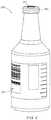
- FIG. 2is a perspective view of a sample reservoir according to an embodiment.
- FIG. 3is a perspective view of a portion of a bodily-fluid collection device according to an embodiment.
- FIG. 4is a perspective view of a sterilization and/or disinfection member, a sample reservoir, and a transfer adapter included in the bodily-fluid collection device of FIG. 3 .
- FIG. 5is a perspective view of a portion of a bodily-fluid collection device in a first configuration, according to an embodiment.
- FIG. 6is a perspective view of at least a portion of a transfer adapter included in the portion of the bodily-fluid collection device of FIG. 5 .
- FIG. 7is a perspective view of a sterilization and/or disinfection member included in the portion of the bodily-fluid collection device of FIG. 5 .
- FIG. 8is a perspective view of a portion of the bodily-fluid collection device of FIG. 5 .
- FIG. 9is a perspective view of the sterilization and/or disinfection member of FIG. 7 , in a second configuration.
- FIG. 10is a perspective view of a portion of the bodily-fluid collection device of FIG. 5 , in a second configuration.
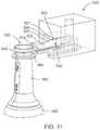
- FIG. 11is a perspective view of a portion of a bodily-fluid collection device in a first configuration, according to an embodiment.
- FIG. 12is a partially exploded view of a sterilization and/or disinfection member and a sample reservoir included in the bodily-fluid collection device of FIG. 11 .
- FIGS. 13 and 14are perspective views of the bodily-fluid collection device of FIG. 11 as the bodily-fluid collection device is transitioned from a first configuration to a second configuration.
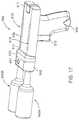
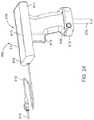
- FIGS. 15-17are perspective views of a bodily-fluid collection device in a first, a second, and a third configuration, respectively, according to an embodiment.
- FIGS. 18-20are perspective views of a bodily-fluid collection device in a first, a second, and a third configuration, respectively, according to another embodiment.
- FIG. 21is a perspective view of the bodily-fluid collection device of FIG. 18 in, for example, in an optional fourth configuration.
- FIGS. 22-24are perspective views of a bodily-fluid collection device in a first, a second, and a third configuration, respectively, according to another embodiment.
- FIG. 25is a flowchart illustrating a method of parentally-procuring bodily-fluid samples with reduced contamination, according to an embodiment.
- an apparatusin some embodiments, includes a fluid reservoir, a sterilization member, and a transfer adapter.
- the fluid reservoirhas an inlet surface and is configured to receive a volume of bodily-fluid transferred from a patient.
- the sterilization memberoperably couples to the fluid reservoir and defines at least a portion of a substantially sterile environment.
- the sterilization memberis configured to be transitioned between a first configuration, in which the sterilization member obstructs the inlet surface and maintains the inlet surface in the substantially sterile environment, and a second configuration, in which the inlet surface is unobstructed.
- the transfer adapteris configured to be placed in fluid communication with a portion of a patient.
- the transfer adapteris configured to move relative to the sterilization member from a first position to a second position.
- a surface of the transfer adapteris configured to contact the sterilization member as the transfer adapter moves to the second position to transition the sterilization member from the first configuration to the second configuration.
- the fluid reservoiris placed in fluid communication with the transfer adapter when the transfer adapter is in the second position.
- a system for parenterally-procuring bodily-fluid samples with reduced contamination from microbes exterior to the bodily-fluid sourceincludes a sample reservoir, a handle, and an adapter.
- the handleis configured to be placed in fluid communication with a patient.
- the handlehas a coupler, a fluid reservoir, and an actuator.
- the fluid reservoiris disposed within the handle and configured to receive a volume of bodily-fluid from the patient.
- the actuatoris configured to be transitioned between a first configuration, in which the coupler is fluidically isolated from the fluid reservoir, and a second configuration, in which the coupler is in fluid communication with the fluid reservoir.
- the adapteris configured to be coupled to the coupler of the handle.
- the adapteris at least temporarily coupled to a sterilization member and to the sample reservoir such that an inlet surface of the sample reservoir is maintained in a substantially sterile environment collectively defined by the adapter and the sterilization member prior to the adapter being coupled to the coupler of the handle.
- the sterilization memberis at least partially removed from the adapter when the adapter is coupled to the coupler of the handle.
- a method for parenterally-procuring bodily-fluid samples with reduced contamination from microbes exterior to the bodily-fluid sourceincludes establishing fluid communication between a patient and a first fluid reservoir, which in turn, is in selective fluid communication with a transfer adapter.
- a volume of bodily-fluidis withdrawn from the patient and into the first fluid reservoir.
- a second fluid reservoiris coupled to the to the transfer adapter.
- the second fluid reservoirhas an inlet surface and is coupled to a sterilization member configured to at least temporarily obstruct the inlet surface. The sterilization member is moved relative to the inlet surface such that the inlet surface is unobstructed by the sterilization member as the second fluid reservoir is coupled to the transfer adapter.
- the second fluid reservoiris placed in fluid communication with the transfer adapter when the portion of the second fluid reservoir is coupled to the transfer adapter and the inlet surface is unobstructed by the sterilization member. Fluid communication between the first fluid reservoir and the second fluid reservoir is established and a volume of bodily-fluid is transferred from the first fluid reservoir to the second fluid reservoir.
- an apparatusincludes a sterilization and/or disinfection member at least temporarily coupled to a sample reservoir.
- the sample reservoirincludes an inlet port that is configured to be fluidically coupled to a transfer device to receive a volume of bodily-fluid directly from a patient or indirectly from the patient via an intermediary bodily-fluid collection device.
- the sterilization and/or disinfection memberis configured to be placed in contact with the transfer device and transitioned from a first configuration, in which the sterilization and/or disinfection member fluidically isolates the inlet port of the fluid reservoir, to a second configuration, in which at least a portion of the sterilization and/or disinfection member is spaced apart from the sample reservoir.
- the sample reservoiris configured to be placed in fluid communication with the transfer device via the inlet port when the sterilization and/or disinfection member is in the second configuration.
- a sterilization and/or disinfection memberis coupled to a sample reservoir during a manufacturing process in a position that prevents the clinician from collecting and/or transferring a bodily-fluid sample into a fluid reservoir(s) without engaging the sterilization and/or disinfection member to at least substantially sterilize a connection therebetween, which in turn, facilitates fluid communication of a bodily-fluid sample between the patient and the collection vessel.
- substantially no external contaminants and/or biological mattere.g., skin cells, tumor cells, organ tissue, etc.
- clinicianscan derive an accurate treatment/action plan, thereby reducing the likelihood of misdiagnosing a patient, prescribing unnecessary treatment, holding the patient in a clinical and/or hospital setting for an undue and/or unnecessary period of time, and/or the like, which in turn, can substantially reduce a risk of the patient developing a further ailment (e.g., antibiotic complications, adverse drug reactions, hospital-acquired infection, and/or the like) as well as substantially reduce costs to hospital and/or other healthcare institutions, third party payers and the healthcare systems as a whole.
- a further ailmente.g., antibiotic complications, adverse drug reactions, hospital-acquired infection, and/or the like
- a memberis intended to mean a single member or a combination of members
- a materialis intended to mean one or more materials, or a combination thereof.
- “bodily-fluid”can include any fluid obtained from a body of a patient, including, but not limited to, blood, cerebrospinal fluid, urine, bile, lymph, saliva, synovial fluid, serous fluid, pleural fluid, amniotic fluid, and the like, or any combination thereof.
- the term “set”can refer to multiple features or a singular feature with multiple parts.
- the set of wallscan be considered as one wall with distinct portions, or the set of walls can be considered as multiple walls.
- a monolithically constructed itemcan include a set of walls.
- Such a set of wallscan include, for example, multiple portions that are in discontinuous from each other.
- a set of wallscan also be fabricated from multiple items that are produced separately and are later joined together (e.g., via a weld, an adhesive or any suitable method).
- proximal and distalrefer to the direction closer to and away from, respectively, a user who would place the device into contact with a patient.
- distal endthe end of a device first touching the body of the patient
- opposite end of the devicee.g., the end of the device being manipulated by the user
- a disinfecting agentrefers to a chemical or combination of chemicals used to disinfect and/or to substantially sterilize or maintain the sterility of a surface.
- a disinfecting agentcan be in any suitable form (e.g., gaseous, aqueous, or solid).
- a disinfecting agentcan be an antiseptic or the like that can be used to kill, destroy, and/or otherwise substantially neutralize negative effects from microbes such as, for example, germs, bacteria, viruses, and/or other target microorganisms.
- a disinfecting agentcan be in an aqueous form and substantially suspended by a porous substrate.
- a surface of a substrate such as a wipe or diaphragmcan be impregnated by and/or coated with a disinfecting agent.
- a disinfecting agentcan include, for example, alcohol (e.g., ethanol, 1-propanol, 2-proponal, isopropanol, and/or the like), quaternary ammonium compounds ((e.g., benzalkonium chloride (BAC), cetyl trimethylammonium bromide (CTMB), cetylpyridinium chloride (Cetrim (CPC)), benzethonium chloride (BZT) and/or the like), boric acid, chlorhexidine gluconate, hydrogen peroxide, iodine, octenidine dihydrochloride, phenol, polyhexanide (e.g., polyhexamethylene biguanide (PHMB)), sodium bicarbonate, silver compounds (e.g., silver nitrate, silver proteinate, chlorhe
- BACbenz
- FIG. 1is a schematic illustration of a bodily-fluid collection device 100 , according to an embodiment.
- the bodily-fluid collection device 100(also referred to herein as “collection device”) is configured to disinfect and/or otherwise maintain the sterility of one or more interfaces prior to defining a fluidic coupling to reduce external contaminants residing on the interfaces.
- the one or more interfacescan be fluidically coupled to allow a flow of bodily-fluid that is substantially free of external contaminants to flow from a patient to a fluid reservoir either directly or via an intermediary device.
- the collection device 100includes a transfer adapter 120 , a fluid reservoir 140 , and a sterilization and/or disinfection member 150 .
- the transfer adapter 120has a proximal end portion 121 and a distal end portion 122 , and defines an inner volume 130 therebetween.
- the transfer adapter 120can be any suitable shape, size, or configuration.
- the transfer adapter 120can be substantially cylindrical, including a set of annular walls that define at least a portion of the inner volume 130 .
- the transfer adapter 120can be polygonal such as rectangular, pentagonal, octagonal, etc.
- the transfer adapter 120(and/or a set of walls of the transfer adapter 120 ) can house and/or receive at least a portion of the fluid reservoir 140 and the sterilization and/or disinfection member 150 .
- the transfer adapter 120can include and/or can be coupled to a puncture member, port, and/or any other suitable transfer device configured to fluidically couple the transfer adapter 120 to an inner volume (not shown) of the fluid reservoir 140 (e.g., a needle that can puncture a port, septum, or portion of the fluid reservoir 140 ).
- the proximal end portion 121 of the transfer adapter 120can be substantially open to movably receive at least a portion of the fluid reservoir 140 .
- at least a portion of the fluid reservoir 140can be inserted through the proximal end portion 121 of the transfer adapter 120 to dispose that portion of the fluid reservoir 140 within the inner volume 130 .
- the fluid reservoir 140can be moved from a first position in which the sterilization and/or disinfection member 150 obstructs, covers, engages, disinfects, and/or otherwise substantially maintains the sterility of a port of the fluid reservoir 140 to a second position in which the sterilization and/or disinfection member 150 is at least partially disengaged from the fluid reservoir 140 to allow access to the port.
- the distal end portion 122 of the transfer adapter 120can be physically and fluidically coupled to any suitable lumen-defining device (e.g., as a catheter, cannula, needle, trocar, or the like), collection device, transfer device, diversion device, and/or the like.
- the distal end portion 122 of the transfer adapter 120can include a port such as a Luer Lok® that can be physically and fluidically coupled to a device configured to receive a flow of bodily-fluids from a patient.
- the transfer adapter 120can be physically and fluidically coupled to a transfer device that includes and/or is coupled to a peripheral intravenous (IV) needle or a peripheral IV catheter, which places the transfer device in fluid communication with a portion of the patient.
- the transfer adapter 120can be placed in fluid communication with any suitable intermediary device, which contains and/or receives a bodily-fluid collected from a patient in a separate and/or independent step.
- the intermediary devicecan be a collection device, a diversion device, a syringe-based collection device and/or the like such as those described in U.S. Pat. No.
- the transfer adapter 120can include a puncture member or the like (as described above) in fluid communication with such a transfer device, which in turn, can puncture a portion, surface, and/or port of the fluid reservoir 140 to establish fluid flow path between the patient and the fluid reservoir 140 .
- a puncture member or the likeas described above
- the transfer adapter 120can be monolithically formed with a transfer device.
- the transfer adapter 120can be operably coupled to a transfer device via any suitable intervening structure (e.g., via sterile flexible tubing, one or more cannulas, one or more intermediate devices, one or more fluid reservoirs, and/or the like).
- any suitable intervening structuree.g., via sterile flexible tubing, one or more cannulas, one or more intermediate devices, one or more fluid reservoirs, and/or the like.
- the transfer adapter 120can include one or more seals and/or disinfection members removably coupled to a surface of the transfer adapter 120 , which, prior to use, can fluidically isolate the inner volume 130 from a volume outside of the transfer adapter 120 .
- the proximal end portion 121 of the transfer adapter 120can include a seal and/or disinfection member that can be removably coupled to a proximal surface of the transfer adapter 120 to substantially cover an opening defined by the proximal end portion 121 .
- Such a sealcan be, for example, a housing, a cap, a relatively thin sheet or film, Tyvek® material, an elastomeric member (e.g., a plunger or stopper), and/or the like.
- the sealcan fluidically isolate the inner volume 130 to substantially maintain the sterility of the inner volume 130 prior to use.
- the transfer adapter 120can include any of the seals and/or disinfection members described in U.S. Patent Publication No. 2015/0246352 entitled, “Apparatus and Methods for Disinfection of a Specimen Container,” filed Mar. 3, 2015, the disclosure of which is incorporated herein by reference in its entirety.
- the fluid reservoir 140is configured to be placed in fluid communication with the transfer adapter 120 to, for example, receive a volume of bodily-fluid from a patient.
- the fluid reservoir 140includes a surface 141 that can be pierced, punctured, and/or otherwise placed in an open configuration to place an inner volume of the fluid reservoir 140 in fluid communication with a volume outside of the fluid reservoir 140 .
- the surface 141can include and/or can define a frangible portion, a port, a septum, and/or the like that can be pierced, for example, by a puncture member included in the transfer adapter 120 to place the inner volume of the fluid reservoir 140 in fluid communication with transfer adapter 120 and any suitable device coupled thereto, as described in further detail herein.
- the fluid reservoir 140can be any suitable shape, size, and/or configuration that can receive and/or store a volume of a bodily-fluid.
- the fluid reservoir 140can be any suitable reservoir described in U.S. Pat. No. 8,197,420 (“the '420 patent”), entitled, “Systems and Methods for Parenterally Procuring Bodily-Fluid Samples with Reduced Contamination,” filed on Dec. 13, 2007, the disclosure of which is incorporated herein by reference in its entirety.
- the fluid reservoir 140can define a negative pressure and/or otherwise can be substantially evacuated.
- the fluid reservoir 140can be a BacT/ALERT® SN or a BacT/ALERT® FA (manufactured by BIOMERIEUX, INC.), a BD Vacutainer® or a BD Microtainer® (manufactured Becton, Dickinson, and Company (BD)), a NanotainerTM (manufactured by Theranos), and/or any suitable reservoir, syringe, vial, microvial, microliter vial, container, microcontainer, or the like.
- the fluid reservoir 140can be any suitable sample or culture bottle such as, for example, an aerobic or anaerobic culture bottle containing a culture medium.
- a bodily-fluid sample volumecan be delivered and/or transferred into the a culture bottle (e.g., the fluid reservoir 140 ) and after a given time, incubation period, or the like, microbes contained in the bodily-fluid sample can flourish or grow within the culture medium. After the incubation period, the bodily-fluid sample can be tested to determine quantitative and/or qualitative information associated with such microbial growth within the culture medium.
- the bodily-fluid samplescan be tested via real-time diagnostics including molecular PCR-based technologies, genetic testing/diagnostics, and/or any other suitable test.
- results of such testingcan be indicative of the presence of Gram-Positive bacteria, Gram-Negative bacteria, fungi, yeast (e.g., Candida ), and/or any other contaminants or organisms contained within the bodily-fluid sample, which in turn, is indicative of their presence within the patient.
- contaminants or microbes external to the body of the patient that are transferred into the inner volume of fluid reservoir 140 and/or otherwise entrained in the flow of the bodily-fluid samplecan result in false positive or false negative results when testing bodily-fluid sample.
- disposing the sterilization and/or disinfection member 150 about a fluidic interface of the fluid reservoir 140 (e.g., at least a portion of the surface 141 ) prior to usecan reduce a likelihood of such contaminants being transferred into the fluid reservoir 140 , as described in further detail herein.
- the sterilization and/or disinfection member 150can be any suitable sterilization and/or disinfection member and/or mechanism that is at least temporarily coupled to a portion of the fluid reservoir 140 to at least temporarily maintain a sterility of the portion of the fluid reservoir 140 .
- the sterilization and/or disinfection member 150can disinfect the portion of the fluid reservoir 140 to remove contaminants and/or the like.
- the sterilization and/or disinfection member 150(also referred to herein as “sterilization member”) can be, for example, a pad, a swab, a diaphragm, a sponge, a wipe, a cap, a foil, and/or the like that can include and/or the can at least partially house a disinfecting agent.
- the sterilization member 150can be a diaphragm or the like that can have at least one surface that is substantially impregnated with a disinfecting agent such as those described above.
- the sterilization member 150can include and/or can define a portion that is substantially porous, for example, to act as a substrate for the disinfection agent.
- the sterilization member 150can include a surface that is formed from a disinfecting material such as, for example, a silver compound.
- the sterilization member 150can be a sheet, foil, cap, membrane, diaphragm, and/or the like that can form a substantially fluid tight seal with a portion of the fluid reservoir 140 .
- the sterilization member 150can be coupled to, in contact with, and/or otherwise disposed about at least a portion of the surface 141 of the fluid reservoir 140 such that at least the portion of the surface 141 is maintained in a substantially sterile environment prior to use.
- such a sterilization member 150can be coupled to the fluid reservoir 140 during a manufacturing process performed in a substantially sterile environment.
- a disinfecting agentcan be disposed within the volume at least partially circumscribed by a seal formed by the sterilization member 150 (e.g., ethylene oxide gas, gamma radiation or the like can be used to create a sterile environment within the inner volume).
- a seal formed by the sterilization member 150e.g., ethylene oxide gas, gamma radiation or the like can be used to create a sterile environment within the inner volume.
- a usere.g., a doctor, nurse, technician, physician, phlebotomist, etc.
- the collection device 100can manipulate the collection device 100 to at least indirectly couple the transfer adapter 120 to a lumen-defining device, transfer device, collection device, diversion device, etc. such as, for example, a standard winged butterfly needle, a syringe, a peripheral IV catheter, and/or the like.
- a lumen-defining devicesuch as, for example, a standard winged butterfly needle, a syringe, a peripheral IV catheter, and/or the like.
- such a devicecan be any of those described in the '241 patent, the '724 patent, the '348 publication, the '782 publication, and/or the '419 publication.
- such a devicecan be placed in communication with a patient prior to being coupled to the transfer adapter 120 .
- the transfer adapter 120can be coupled to, for example, a needle or cannula prior to being inserted (e.g., percutaneously) into the patient.
- the usercan manipulate the collection device 100 to insert at least a portion of the fluid reservoir 140 into the proximal end portion 121 of the transfer adapter 120 .
- the userprior to inserting the fluid reservoir 140 , the user can manipulate the collection device 100 to remove, for example, a seal that substantially covers the proximal end 121 of the transfer adapter 120 , as described above.
- the usercan move the fluid reservoir 140 relative to the transfer adapter 120 to place the fluid reservoir 140 in a first position within the inner volume 130 , thereby placing the collection device 100 in a first configuration.
- the sterilization member 150can be placed in contact with a portion of the transfer adapter 120 such as an inner surface and/or any suitable feature extending from the inner surface when the collection device 100 is in the first configuration.
- the inner surface of the transfer adapter 120can include a surface feature, contour, protrusion, slot, cutting member, peeling member, and/or the like configured to engage the sterilization member 150 as the fluid reservoir 140 is inserted and/or moved within the inner volume 130 of the transfer adapter 120 .
- the usercan maintain the fluid reservoir 140 in the first position for a predetermined time (which in some embodiments, is facilitated by physical design characteristics that prevent the user from bypassing the first position) to ensure the sterilization member 150 is engaged with and/or otherwise in contact with a desired portion of the transfer adapter 120 prior to moving the fluid reservoir 140 from the first position to a second position within the transfer adapter 120 .
- the fluid reservoir 140need not be held in the first position for the predetermined time. That is to say, in some embodiments, the user can move the fluid reservoir 140 relative to the transfer adapter 120 (or vice versa) in a substantially continuous manner to move the fluid reservoir 140 through the first position and into the second position.
- a portion of the surface 141can be exposed and/or otherwise unobstructed by the sterilization member 150 .
- placing the fluid reservoir 140 in a desired position within the transfer adapter 120can transition the sterilization member 150 from a first configuration, in which the sterilization member 150 engages the surface 141 to substantially maintain the sterility of at least a portion of the surface 141 , to a second configuration, in which at least a portion of the sterilization member 150 is disengaged from the surface 141 .
- the transfer adapter 120can remove at least a portion of the sterilization member 150 from contact with the surface 141 as the fluid reservoir 140 is placed in the second position, as indicated by the arrow AA in FIG. 1 .
- the collection device 100can be used to maintain the sterility of a fluidic interface associated with the surface 141 of the fluid reservoir 140 to reduce the likelihood of contamination from microbes disposed on the surface 141 .
- contamination of a sample of bodily-fluidcan be reduced that might otherwise result from insufficient disinfection by a user.
- transfer adapter 120automatically remove the sterilization member 150 as the fluid reservoir 140 is moved relative to the transfer adapter 120 can ensure compliance with a substantially consistent sterilization and/or disinfection process, which in turn, can reduce inaccurate test results, costs, and time associated with collecting and testing a sample volume.
- the collection device 100 and/or the transfer adapter 120can be included in and/or can form at least a portion of a preassembled and/or all-in-one collection device.
- the preassembled and/or all-in-one collection devicecan include, for example, any suitable number of fluid reservoirs (e.g., one fluid reservoir, two fluid reservoirs, three fluid reservoirs, four fluid reservoirs, or more) that can be preassembled with and/or incorporated in (e.g., unitarily formed with) a transfer device including a sterilization and/or disinfection member such as those described herein.
- the collection device 100(and/or any suitable portion thereof) can be included in and/or can otherwise form a portion of a preassembled and/or all-in-one collection device such as those described in '782 publication incorporated by reference above.
- the sterilization member 150can be configured to disinfect the surface 141 of the fluid reservoir 140 . That is to say, the sterilization member 150 can be used to remove contaminants from the surface 141 of the fluid reservoir 140 (i.e., to disinfect the surface 141 of the fluid reservoir 140 ).
- the sterilization and/or disinfection members described herein, therefore,are not intended to be limited to either function and, for simplicity, are referred to henceforth as “sterilization members.”
- a fluid reservoir 240 or sample containeris illustrated according to an embodiment.
- the fluid reservoir 240can be used and/or included in, for example, the collection device 100 described above.
- the fluid reservoir 240can be coupled to and/or can include a sterilization member configured, for example, to maintain a sterility of a portion of the fluid reservoir 240 (e.g., a proximal surface) prior to use.
- the fluid reservoir 240can be positioned within and/or can engage a transfer adapter (e.g., such as the transfer adapter 120 ) and can be moved relative thereto to 1) automatically disengage at least a portion of the sterilization member, for example, from the proximal surface and 2) place the fluid reservoir 240 in fluid communication with the transfer adapter, as described in further detail herein with respect to specific embodiments.
- a transfer adaptere.g., such as the transfer adapter 120
- the fluid reservoir 240can be any suitable reservoir for containing a bodily-fluid, including, for example, a single use disposable collection reservoir, a vacuum based collection reservoir (e.g., maintaining negative pressure conditions that can produce a suction or vacuum force), a sample reservoir as described in the '420 patent, and/or the like. While shown as having a bottle shape or the like, the fluid reservoir 240 can be any suitable bottle, tube, vial, microvial, container, syringe, etc. In some embodiments, the reservoir 240 can be an aerobic culture bottle or an anaerobic culture bottles.
- the fluid reservoir 240can include an aerobic or anaerobic culture medium disposed within an inner volume defined by the fluid reservoir 240 , as described in detail above with reference to the fluid reservoir 140 .
- the culture medium disposed thereincan be associated with one or more tests, procedures, and/or actions configured to, for example, detect the presence of certain microbes that are known to thrive in that medium.
- the fluid reservoir 240can include common additives such as heparin, citrate, ethylenediaminetetraacetic acid (EDTA), oxalate, and/or the like that are used to preserve specific characteristics and/or qualities of a bodily-fluid sample (e.g., blood) prior to diagnostic analysis.
- EDTAethylenediaminetetraacetic acid
- the fluid reservoir 240includes a proximal surface 241 , a proximal rim 243 , and a label 242 .
- the proximal surface 241can include and/or can otherwise form a port, septum, frangible portion or the like, which can be transitioned from a substantially sealed configuration to a substantially unsealed configuration to place an inner volume of the fluid reservoir in fluid communication with a volume outside of the fluid reservoir 240 , as described in detail above.
- the proximal surface 241can be, for example, an inlet surface.
- the proximal rim 243can be, for example, a flange, a rib, a rolled portion, and/or the like.
- the proximal rim 243 of the fluid reservoir 240can be removably coupled to a sterilization member such as those described herein.
- a sterilization membersuch as those described herein.
- such a sterilization membercan be coupled to the proximal rim 243 during a manufacturing process or the like such that at least a portion of the proximal surface 241 is maintained in a substantially sterile environment prior to use, as described in further detail herein.
- the label 242is disposed about a portion of the fluid reservoir 240 .
- the label 242can be and/or can include a tag or indicia associated with one or more characteristics of the fluid reservoir 240 .
- the label 242can include a code portion such as, for example, a serial number, bar code, a quick response (QR) code, a radio-frequency identification (RFID) tag, a near field communication (NFC) tag, and/or the like.
- the code portioncan provide a user (e.g., a doctor, phlebotomist, nurse, technician, etc.) with information associated with the fluid reservoir 240 such as, for example, the type of culture medium or additive (as described above) disposed therein, the amount (e.g., volume, mass, density, etc.) of the culture medium or additive (as described above) disposed therein, a volume of bodily-fluid that the fluid reservoir 240 should receive, a tolerance value, the type of tests to be performed on the bodily-fluid sample disposed therein, temperature, and/or the like.
- the usercan determine, inter alia, the amount or the volume of bodily-fluid that he or she should transfer into the fluid reservoir 240 .
- the label 242can include a volumetric indicator portion or the like that can provide a visual indicator associated with the bodily-fluid disposed in the fluid reservoir 240 .
- the volumetric indicator portioncan include a set of evenly spaced lines, tic marks, dashes, arrows, markers, and/or any other suitable gradation or indicia that can be associated with a specific volume of the fluid reservoir 240 if filled to that point.
- the fluid reservoir 240can be substantially transparent, allowing the user to visualize the sample disposed therein.
- a usercan visually assess the volume of the bodily-fluid disposed in the fluid reservoir 240 by determining at what point along the indicator portion the meniscus of the bodily-fluid aligns.
- a devicecan be coupled to the fluid reservoir 240 that is configured to verify and/or otherwise indicate a volume of bodily-fluid transferred into the fluid reservoir such as, for example, those described in U.S. patent application Ser. No. 15/146,967 entitled, “Devices and Methods for Verifying a Sample Volume,” filed May 5, 2016, the disclosure of which is incorporated herein by reference in its entirety.
- verifying and/or otherwise indicating a volume of bodily-fluid transferred into the fluid reservoircan facilitate the transfer of a desired and/or predetermined volume of the bodily-fluid into the fluid reservoir, which in turn, can limit false test results otherwise associated with an undesirable volume of the bodily-fluid (e.g., too much bodily-fluid or too little bodily-fluid for a given test or tests).
- the fluid reservoir 240can be any suitable shape, size, and/or configuration.
- the fluid reservoir 240is shown and described as including the label 242 configured to provide a user with information associated with the fluid reservoir 240 , in other embodiments, a fluid reservoir without a label and/or other identifying portion can be used.
- the fluid reservoir 240can be coupled to and/or can include a sterilization member that can be at least partially disengaged from the fluid reservoir 240 when the fluid reservoir 240 is positioned within a transfer adapter or device.
- FIGS. 3 and 4illustrate at least a portion of a collection device 300 according to an embodiment.
- the collection device 300(or portion thereof) includes a transfer adapter 320 configured to receive a portion of at least one fluid reservoir 340 and at least one sterilization member 350 .
- the transfer adapter 320can be operable to transition the at least one sterilization members 350 from a first configuration, in which the one or more sterilization members 350 substantially maintain the sterility of a portion of the one or more fluid reservoirs 340 , to a second configuration in which the one or more sterilization members 350 are at least partially disengaged from the one or more fluid reservoirs 340 to allow the fluid reservoirs 340 to be placed in fluid communication with the transfer adapter 320 , as described in further detail herein.
- the collection device 300(or portion thereof) as shown in FIG. 3 , includes a reservoir housing 345 that contains, houses, and/or otherwise receives two fluid reservoirs 340 (e.g., a first fluid reservoir 340 and a second fluid reservoir 340 ). In other embodiments, any number of fluid reservoirs 340 can be contained within the housing 345 .
- the fluid reservoirs 340can be any suitable shape, size, and/or configuration. For example, in some embodiments, the fluid reservoirs 340 are substantially similar to and/or the same as the fluid reservoir 240 described above with reference to FIG. 2 . Thus, the fluid reservoirs 340 are not described in further detail herein.
- the housing 345can be any suitable shape, size, and/or configuration.
- the housing 345can have a size and/or shape that is associated with a size and/or shape of the fluid reservoir to be disposed therein. More particularly, the housing 345 defines an inner volume that is sufficient to receive at least the first and second fluid reservoir 340 .
- the housing 345is coupled to the sterilization member 350 , which is configured to at least temporarily fluidically isolate the inner volume of the housing 345 from a volume outside of the housing 345 .
- the housing 345can be an enclosure that defines one or more openings defined by a sidewall or the like through which the fluid reservoirs 340 are inserted to be disposed within the inner volume.
- the sterilization member 350is coupled to the sidewall defining the opening to at least temporarily seal the inner volume of the housing 345 .
- the sterilization member 350can be coupled to and/or in contact with a surface of the sidewall such that the surface of the sidewall and the sterilization member 350 collectively define a fluid tight seal.
- the sterilization member 350can be coupled to the surface via an adhesive, a standard medical sealing process using, for example, Tyvek, ultrasonic weld, or the like. In this manner, the inner volume of the housing 345 is substantially fluidically isolated from a volume outside of the housing 345 .
- the fluid reservoirs 340can be disposed in the housing 345 and the sterilization member 350 can be coupled to the housing 345 during manufacturing.
- the housing 345can be substantially sterilized using standard medical sterilization practices (e.g. ethylene oxide, gamma radiation, e-beam, and/or the like) to facilitate maintenance of a sterile environment.
- the fluid reservoirs 340can be substantially sterilized and disposed in the inner volume of the housing 345 while the housing 345 and the fluid reservoirs 340 are in the sterile environment.
- the sterilization member 350can be substantially sterilized and coupled to the housing 345 , after the fluid reservoirs 340 have been disposed therein, while the housing 345 , the fluid reservoirs 340 , and the sterilization member 350 are disposed in the sterile environment.
- the inner volume of the housing 345(containing the fluid reservoirs 340 ) is a substantially sterile volume and/or environment.
- housing 345 , fluid reservoirs 340 , sterilization member 350can be assembled (as described above) in a sterile environment such as ethylene oxide gas or the like.
- the fluid reservoirs 340 within the inner volume of the housing 345are maintained in, for example, an ethylene oxide gas environment until the housing 345 is unsealed.
- the sterilization member 350can be any shape, size, and/or configuration suitable for coupling to the housing 345 .
- the sterilization member 350can be one or more films, foils, sheets, membranes, diaphragms, and/or the like.
- the sterilization member 350can include a first portion 356 that is removably coupled to a second portion 357 .
- the first portion 356can be, for example, a base configured to be coupled to the housing 345 .
- the first portion 356can be formed from a relatively stiff material that can provide structural integrity for the sterilization member 350 to be coupled to the housing 345 .
- the second portion 357can be removably coupled to the first portion 356 and can be formed from a relatively flexible material to allow the second portion 357 to deform, bend, fold, peel, and/or otherwise at least partially disengage from the first portion 356 .
- a surface of the sterilization member 350e.g., of the first portion 356 in contact with the surface of the housing 345 can have and/or can define an area that is greater than an area defined by the surface of the housing 345 .
- the sterilization member 350can form a flange or the like that extends beyond a perimeter of the housing 345 , as shown in FIG. 3 and as described in further detail herein.
- the arrangement of the sterilization member 350is such that the second portion 357 is coupled to the first portion 356 to form a substantially fluid tight seal and/or interface.
- a perimeter of the second portion 357(or an area near a perimeter) can be coupled to an associated perimeter of the first portion 356 via an adhesive or ultrasonic weld.
- substantially the entirety of a surface of the second portion 357can be adhered to substantially the entirety of a surface of the first portion 356 .
- the second portion 357can be coupled to the first portion 356 in any suitable manner.
- the second portion 357is coupled to the first portion 356 in such a manner that the first portion 356 and the second portion 357 collectively form a substantially sterile area.
- a substantially sterile areacan be circumscribed by a seal defined by the coupling of the second portion 357 to the first portion 356 .
- the second portion 357can be coupled to the first portion 356 via an adhesive, which in turn, is impregnated with and/or otherwise includes a sterilizing agent such as those described above.
- the transfer adapter 320can be any suitable transfer adapter.
- the transfer adapter 320can be substantially similar to the transfer adapter 120 described above with reference to FIG. 1 .
- aspects of the transfer adapter 320are not described in further detail herein.
- the transfer adapter 320includes an inner surface 323 that defines an inner volume 330 configured to receive a portion of the housing 345 and at least a portion of the sterilization member 350 .
- the transfer adapter 320can include a puncture member, a port, a transfer member, and/or the like configured to establish fluid communication between the transfer adapter 320 and the fluid reservoirs 340 .
- the inner surface 323defines a set of channels 324 configured to engage a portion of the sterilization member 350 as the housing 345 is inserted into the inner volume 330 . More particularly, the channels 324 can slidably receive a portion of the sterilization member 350 that extends beyond the perimeter of the housing 345 (as described above) and can define a substantially linear range of motion of the housing 345 and the sterilization member 350 relative to the transfer adapter 320 .
- the arrangement of the channels 324can be such that as the sterilization member 350 is inserted into the channels 324 and the housing 345 is moved relative to the transfer adapter 320 , a portion of the inner surface of the transfer adapter 320 defining the channels 324 peels, removes, decouples, and/or otherwise disengages the second portion 357 of the sterilization member 350 from the first portion 356 of the sterilization member 350 , thereby exposing a surface of the first portion 356 that is aligned with and/or otherwise covers at least a portion of the opening defined by the housing 345 .
- a usercan place the transfer adapter 320 in fluid communication with a lumen-defining device, transfer device, collection device, diversion device, and/or the like, which in turn, is in fluid communication with a portion of the body of a patient or an intermediary device containing a bodily-fluid, as described in detail above with reference to the transfer adapter 120 .
- the housing 345 , the fluid reservoirs 340 , and the sterilization member 350can be in a first configuration in which the sterilization member 350 seals the inner volume of the housing 345 such that the fluid reservoirs 340 disposed therein are maintained in a substantially sterile environment.
- the usercan manipulate the transfer adapter 320 and/or the housing 345 to insert the portion of the sterilization member 350 into the channels 324 .
- the portion of the inner surface 323 that defines the channels 323is placed in contact with the sterilization member 350 .
- the portion of the inner surface 323disengages, peels, and/or otherwise decouples the second portion 357 of the sterilization member 350 from the first portion 356 of the sterilization member 350 .
- the substantially sterile surface of the first portion 356 that is aligned with and/or otherwise covers at least a portion of the opening defined by the housing 345is exposed.
- the usercan manipulate the collection device 300 (or portion thereof) to place the transfer adapter 320 in fluid communication with at least one of the fluid reservoirs 340 .
- the usercan actuate an actuator configured to advance a puncture member or the like through a surface of the fluid reservoir 340 , thereby placing at least one of the fluid reservoirs 340 in fluid communication with the patient.
- at least one of the fluid reservoirs 340can receive a flow of bodily-fluid from the patient or an intermediary device containing a bodily-fluid.
- the arrangement of the collection device 300(or portion thereof) is such that the sterility of the fluid reservoirs 340 within the housing 345 and the surface of the first portion 356 of the sterilization member 350 is maintained until a time relatively shortly before the transfer adapter 320 is placed in fluid communication with the fluid reservoirs 340 .
- the transfer adapter 320can include and/or can be coupled to any suitable sterilization member or mechanism that can be configured to maintain the sterility of, for example, a puncture member or other transfer means until a time relatively shortly before the transfer adapter 320 is placed in fluid communication with the fluid reservoirs 340 .
- the probability of external contaminants being transferred into the bodily-fluid sample received by the fluid reservoirs 340can be reduced.
- pre-sterilizing fluidic interfaces and automatically exposing those fluidic interfaces just before establishing fluid communication between the transfer adapter 320 and the fluid reservoir 340can increase compliance with sterilization protocols and ease of performing the procedure, as well as reduce costs and inadvertent mistakes.
- FIGS. 5-10illustrate at least a portion of a collection device 400 according to another embodiment.
- the collection device 400includes a transfer adapter 420 , at least one fluid reservoir 440 , and at least one sterilization member 450 .
- FIGS. 5-10illustrates two fluid reservoirs 440 , each of which can be similar to or substantially the same as the fluid reservoir 240 described above with reference to FIG. 2 .
- aspects of the collection device 400 similar in form and function to associated and/or corresponding aspects of the collection devices, and/or components thereof, described aboveare not described in further detail herein.
- the collection device 400is shown in FIG.
- the collection device 400can include a transfer adapter configured to receive one fluid reservoir and one sterilization member. In still other embodiments, the collection device 400 can include a transfer adapter configured to receive more than two fluid reservoirs and more than two sterilization members.
- the two fluid reservoirs 440can be substantially the same unless otherwise indicated and the two sterilization members 450 can be substantially the same unless otherwise indicated.
- a discussion of a single fluid reservoir (e.g., the fluid reservoir 440 ) and a single sterilization member (e.g., the sterilization member 450 )can similarly apply to any number of fluid reservoirs and any number of sterilization members, respectively, included in the collection device 400 .
- the transfer adapter 420 of the collection device 400can be any suitable transfer adapter.
- the transfer adapter 420can be substantially similar to the transfer adapter 120 described above with reference to FIG. 1 .
- the transfer adapter 420includes an inner surface 423 that defines an inner volume 430 configured to receive a portion of the fluid reservoir 440 and at least a portion of the sterilization member 450 .
- the transfer adapter 420can include a puncture member, a port, a transfer member, and/or the like configured to establish fluid communication between the transfer adapter 420 and the fluid reservoirs 440 .
- the inner surface 423defines a set of channels 424 configured to engage a portion of the sterilization member 450 as the fluid reservoir 440 is inserted into the inner volume 430 .
- the channels 424can slidably receive a portion of the sterilization member 450 to guide the sterilization member 450 and/or the fluid reservoir 440 to which it is coupled as the fluid reservoir 440 is moved relative to the transfer adapter 420 , as described in further detail herein.
- the transfer adapter 420 and/or the inner surface 423 thereofincludes an engagement portion 426 configured to engage a seal 457 or the like of the sterilization member 450 as the sterilization member 450 is moved relative to the transfer adapter 420 (e.g., as the portion of the sterilization member 450 is moved within the channels 424 as a result of the fluid reservoir 440 being moved relative to the transfer adapter 420 ).
- the engagement portion 426can extend from the inner surface 423 and can include a protrusion, tab, flange, etc. configured to be placed in contact with a portion of the seal 457 of the sterilization member 450 .
- the engagement portion 426is operable in transitioning the sterilization member 450 from a first configuration to a second configuration, as described in further detail herein.
- the sterilization member 450 of the collection device 400can be any suitable sterilization member and/or mechanism.
- the sterilization member 450is a cap or the like coupled to a portion of the fluid reservoir 440 . More particularly, the sterilization member 450 defines an inner volume 451 within which at a portion of the fluid reservoir 440 is disposed.
- the sterilization member 450can be coupled to the fluid reservoir 440 during a manufacturing process (e.g., as described above with reference to the fluid reservoirs 340 and sterilization member 350 ). In other embodiments, the sterilization member 450 can be coupled to the fluid reservoir 440 prior to use (e.g., by a user).
- the sterilization member 450when the sterilization member 450 is coupled to the fluid reservoir 440 , the sterilization member 450 is configured to maintain a fluidic interface of the fluid reservoir 440 (e.g., a surface, port, etc.) in a substantially sterile environment prior to use, as described in further detail herein.
- the sterilization member 450can include and/or can be coupled to a pad, a swab, a sponge or porous material, and/or the like that can include a disinfecting agent such as those described herein.
- at least a surface of the sterilization member 450can be impregnated with a disinfecting agent such as, those described above.
- the sterilization members 450can include and/or can define a portion that is substantially porous, for example, to act as a substrate for the disinfection agent. In this manner, the sterilization member 450 can be disposed about a portion of the fluid reservoir 440 to maintain the sterility of the portion of the fluid reservoir 440 prior to use.
- the sterilization member 450includes a flange 463 having a guide portion 452 and a ramp portion 453 .
- the flange 463extends from the sterilization member 450 such that at least a portion of the flange 463 can be inserted in the channels 424 as the sterilization member 450 is moved within the inner volume 430 .
- a portion of the guide portion 452can, for example, orient the sterilization member 450 relative to the transfer adapter 420 as the sterilization member 450 is inserted into the inner volume 430 . For example, as shown in FIG.
- the guide portion 452can extend from the flange 463 and can include, for example, two protrusions, ribs, tabs, bends, etc. configured to be inserted into a portion of the channels 424 of the inner surface 423 having a similar configuration.
- the channels 424 defined by the inner surface 423 of the transfer adapter 420are configured to receive an associated sterilization member 450 in a predetermined orientation and/or the like.
- the arrangement of the guide portion 452can be associated with a particular type of fluid reservoir.
- a sterilization membercan include and/or can have a guide portion disposed on a first side and can be coupled to, for example, an aerobic culture bottle.
- the sterilization membercan include and/or can have a guide portion disposed on a second side, opposite the first side, and can be coupled to, for example, an anaerobic culture bottle.
- a sterilization memberneed not be associated with predetermined type of fluid reservoir.
- the sterilization member 450includes the seal 457 .
- the seal 457can be a sheet, foil, tape, and/or the like at least temporarily coupled to a surface of the flange 463 and configured to maintain at least a portion of the surface of the flange 463 in a substantially sterile configuration prior to use.
- the sterilization member 450can include and/or define an opening 455 or port, which is substantially covered, obstructed, or otherwise in contact with the seal 457 .
- the seal 457is at least temporarily coupled to a surface of the sterilization member 450 to at least temporarily fluidically isolate the opening 455 defined by the sterilization member 450 , as described in further detail herein.
- a portion of the seal 457defines an aperture and is disposed on the ramp portion 453 of the flange 463 .
- the arrangement of the portion of the seal 457 and the ramp portion 453is such that, as the sterilization member is moved within the inner volume 430 , the portion of the seal 457 disposed on and/or otherwise in contact with the ramp portion 453 of the sterilization member 450 is placed in contact with the engagement portion 426 of the inner surface 423 of the transfer adapter 420 .
- the engagement portion 426therefore, is operable in transitioning the sterilization member 450 from the first configuration (see e.g., FIGS. 5-7 ) to the second configuration (see e.g., FIGS. 8-10 ), as described in further detail herein.
- a usercan place the transfer adapter 420 in fluid communication with a lumen-defining device, transfer device, collection device, diversion device, and/or the like, which in turn, is in fluid communication with a portion of the body of a patient (or intermediary device containing a bodily-fluid, as described in detail above with reference to the transfer adapter 120 .
- the fluid reservoirs 440 and the sterilization member 450can be in a first configuration in which the sterilization member 450 maintains the sterility of at least the portion of the fluid reservoir 440 (e.g., a fluidic interface such as a surface or port).
- the usercan manipulate the transfer adapter 420 and/or the fluid reservoir 440 to insert the portion of the sterilization member 450 into the channels 424 , as described above with reference to the collection device 300 .
- the engagement portion 426 of the inner surface 423is placed in contact with the portion of the seal 457 of the sterilization member 450 .
- the ramp portion 453 of the sterilization member 450defines a channel 454 or slot that exposes the portion of the seal 457 defining the aperture 458 .
- such an arrangementremoves, disengages, peels, and/or otherwise decouples a portion of the seal 457 from the surface of the sterilization member 450 .
- the seal 457is sufficiently removed from the surface of the sterilization member 450 such that the opening 455 or port is exposed.
- the usercan manipulate the collection device 400 (or portion thereof) to place the transfer adapter 420 in fluid communication with at least one of the fluid reservoirs 440 .
- the usercan actuate an actuator configured to advance a puncture member or the like through the opening 455 of the sterilization member 450 and through a surface or port of the fluid reservoir 440 , thereby placing at least one of the fluid reservoirs 440 in fluid communication with the patient or an intermediary device containing a bodily-fluid.
- coupling the collection device 400 to the fluid reservoirs 440can automatically facilitate access such that bodily-fluid flow begins as soon as physical coupling is complete.
- the fluid reservoir 440can receive a flow of bodily-fluid from the patient or intermediary device containing bodily-fluid.
- the arrangement of the collection device 400(or portion thereof) is such that the sterility of at least the portion of the fluid reservoir 440 in contact with the sterilization member 450 is maintained until a time relatively shortly before the transfer adapter 420 is placed in fluid communication with the fluid reservoir 440 .
- the probability of external contaminants being transferred into the bodily-fluid sample received by the fluid reservoir 440can be reduced.
- pre-sterilizing fluidic interfaces and automatically exposing those fluidic interfaces just before establishing fluid communication between the transfer adapter 420 and the fluid reservoir 440can increase compliance with sterilization protocols and ease of performing the procedure, as well as reduce costs and inadvertent mistakes.
- the collection device 500includes a transfer adapter 520 , a fluid reservoir 540 , and a sterilization member 550 .
- Some aspects of the collection device 500can be similar in form and function to associated aspects of the collection devices 100 , 200 , 300 , and/or 400 (and/or components thereof) described above.
- the embodiment shown in FIGS. 11-14illustrates the fluid reservoir 540 , which can be similar to or substantially the same as the fluid reservoir 240 described above with reference to FIG. 2 .
- aspects of the collection device 500 similar in form and function to associated and/or corresponding aspects of the collection devices, and/or components thereof, described aboveare not described in further detail herein.
- the transfer adapter 520 of the collection device 500can be any suitable transfer adapter.
- the transfer adapter 520can be substantially similar in form and/or function to the transfer adapters 120 , 220 , 320 , and/or 420 described above. Thus, aspects of the transfer adapter 520 are not described in further detail herein.
- the transfer adapter 520includes an inner surface 523 that defines an inner volume 530 configured to receive a portion of the fluid reservoir 540 and the sterilization member 550 .
- the transfer adapter 520can include a puncture member, a port, a transfer member, and/or the like configured to establish fluid communication between the transfer adapter 520 and the fluid reservoirs 540 .
- the transfer adapter 520can include a puncture member such as a sheathed needle or the like that can pierce or puncture a surface 541 of the fluid reservoir 540 (see e.g., FIG. 14 ) to establish fluid communication between the transfer adapter 520 and the fluid reservoir 540 .
- the inner surface 523includes a first portion 525 and a second portion 527 .
- the first portion 525defines a set of channels 524 configured to engage a portion of the sterilization member 550 as the fluid reservoir 540 is inserted into the inner volume 530 , as described above with reference to the transfer adapter 320 and 420 .
- the channels 524can slidably receive a portion of the sterilization member 550 to guide the sterilization member 550 and/or the fluid reservoir 540 to which it is coupled when the fluid reservoir 540 is moved relative to the transfer adapter 520 , as described in further detail herein.
- the first portion 525 of the inner surface 523has a width defined between opposite sides of the first portion 525 that is less than a width defined between opposite sides of the second portion 525 .
- the first portion 525 of the inner surface 523has a depth that is greater than a depth of the second portion 527 of the inner surface 523 .
- This arrangement of the inner surface 523forms an edge surface 528 or corner that is associated with a difference between the width of the first portion 525 and the width of the second portion 527 .
- the edge surface 528extends along the depth of the second portion 527 and includes, for example, a ramp portion 529 or the like.
- a portion of the sterilization member 550is configured to be placed in contact with the edge surface 528 when the sterilization member 550 is inserted into the inner volume.
- the sterilization member 550 of the collection device 500can be any suitable sterilization member and/or mechanism.
- the sterilization member 550is a cap or the like coupled to a portion of the fluid reservoir 540 .
- the sterilization member 550can be formed from a relatively flexible material and can be coupled to a proximal rim 543 of the fluid reservoir 540 via a friction fit, press fit, threaded coupling, and/or the like.
- the sterilization member 550is configured to be coupled to the fluid reservoir 540 to obstruct and/or fluidically isolate the surface 541 of the fluid reservoir 540 .
- the sterilization member 550can be coupled to the fluid reservoir 540 during a manufacturing process (e.g., as described above with reference to the fluid reservoirs 340 and sterilization member 350 ). In other embodiments, the sterilization member 550 can be coupled to the fluid reservoir 540 prior to use (e.g., by a user). Moreover, when the sterilization member 550 is coupled to the fluid reservoir 540 , the sterilization member 550 is configured to maintain the surface 541 (e.g., a fluidic interface, port, etc.) of the fluid reservoir 540 in a substantially sterile environment prior to use, as described in detail above.
- the surface 541e.g., a fluidic interface, port, etc.
- the sterilization member 550includes a collar 560 or the like having a first portion 561 and a second portion 562 .
- the first portion 561 and the second portion 562 of the collar 560can be positioned about a portion of the fluid reservoir 560 and coupled (e.g., via a snap fit, interference fit, etc.) to couple the collar 560 to the fluid reservoir 540 .
- the collar 560forms a flange 563 or the like configured to be inserted into the channels 524 of the transfer adapter 520 as the sterilization member 550 is moved within the inner volume 530 , as described in detail above. In this manner, the flange 563 can, for example, orient and/or direct the sterilization member 550 relative to the transfer adapter 520 as the sterilization member 550 is inserted into the inner volume 530 .
- a usercan place the transfer adapter 520 in fluid communication with a lumen-defining device, transfer device, collection device, diversion device, and/or the like, which in turn, is in fluid communication with a portion of the body of a patient (or intermediary device containing a bodily-fluid, as described in detail above with reference to the transfer adapter 120 .
- the fluid reservoir 540 and the sterilization member 550can be in a first configuration in which the sterilization member 550 obstructs, covers, and/or otherwise fluidically isolates the surface 541 of the fluid reservoir to substantially maintain the sterility of the surface 541 .
- the usercan manipulate the transfer adapter 520 and/or the fluid reservoir 540 to insert the flange 563 of the collar 560 into the channels 524 , as described above, for example, with reference to the collection device 300 .
- sterilization member 550is placed in contact with the edge surface 528 , as shown in FIG. 13 .
- coupling the collar 560 about the fluid reservoir 540 and disposing the flange 563 in the channels 524places the sterilization member 550 in a predetermined position (e.g., height) relative to the transfer adapter 520 .
- the predetermined positioncan be a position in which the sterilization member 550 is placed in contact with the edge surface 528 .
- the sterilization member 550is advanced relative to the transfer adapter 520 , the sterilization member 550 is placed in contact with the ramp portion 529 of the edge surface 528 , as shown in FIG. 13 .
- the sterilization member 550With the sterilization member 550 in contact with the ramp portion 529 of the edge surface 528 , further movement of the sterilization member 550 into the inner volume 530 advances the sterilization member 550 relative to the ramp portion 529 , which in turn, removes, disengages, peels, and/or otherwise decouples the sterilization member 550 from the fluid reservoir 540 , as shown in FIG. 14 .
- the sterilization member 550is in contact with the edge surface 528 and disposed within a portion of the inner volume 530 defined by the second portion 527 of the inner surface 523 .
- the fluid reservoir 540With the sterilization member 550 decoupled from the fluid reservoir 540 , the fluid reservoir 540 can be moved within the inner volume 530 relative to the sterilization member 550 and placed in a desired position.
- the fluid reservoir 540can be advanced within the inner volume 530 to a depth that is substantially beyond the second portion 527 of the inner surface 523 , as shown in FIG. 14 .
- the desired position of the fluid reservoir 540 within the transfer adapter 520can substantially align a portion of the surface 541 (e.g., a port or other fluidic interface) with a transfer member (e.g., a puncture member such as a sheathed needle or the like).
- a transfer membere.g., a puncture member such as a sheathed needle or the like.
- the usercan actuate an actuator configured to advance a puncture member or the like through a port or fluidic interface of the surface 541 of the fluid reservoir 540 , thereby placing the fluid reservoir 540 in fluid communication with the patient.
- an actuatorconfigured to advance a puncture member or the like through a port or fluidic interface of the surface 541 of the fluid reservoir 540 , thereby placing the fluid reservoir 540 in fluid communication with the patient.
- the physical process of coupling the collection device 500 to the fluid reservoir 540 via the transfer adapter 520automatically facilitates a flow path for bodily-fluid without specific user manipulation.
- the fluid reservoir 540can receive a flow of bodily-fluid from the patient or intermediary device containing a bodily fluid.
- the arrangement of the collection device 500is such that the sterility of at least the surface 541 of the fluid reservoir 540 is maintained until a time relatively shortly before the transfer adapter 520 is placed in fluid communication with the fluid reservoir 540 .
- the probability of external contaminants being transferred into the bodily-fluid sample received by the fluid reservoir 540can be reduced.
- pre-sterilizing fluidic interfaces and automatically exposing those fluidic interfaces just before establishing fluid communication between the transfer adapter 520 and the fluid reservoir 540can increase compliance with sterilization protocols and ease of performing the procedure, as well as reduce costs and inadvertent mistakes.
- the transfer adapters 120 , 220 , 320 , 420 , and 520can be included in and/or coupled to any suitable device configured to receive a fluid of bodily-fluid from a patient.
- Such devicescan be any suitable collection device, transfer device, diversion device, and/or the like.
- FIGS. 15-17illustrate a collection device 600 according to an embodiment.
- the collection device 600can be any suitable device configured to withdraw and/or receive bodily-fluid from a patient.
- the collection device 600can be used in conjunction with any of the transfer adapters, sterilization members, and/or fluid reservoirs described herein.
- the arrangement of the collection device 600can minimize fluid interfaces or the like, which in turn, can reduce a likelihood of a sample becoming contaminated by external contaminants.
- the collection device 600includes and/or forms a handle 610 having a proximal end portion 611 and a distal end portion 612 .
- the distal end portion 612 of the handle 610can include and/or can be coupled to any suitable port 614 or the like configured to be placed in fluid communication with one or more fluid reservoirs.
- the proximal end portion 611 of the handle 610includes at least two ports 614 configured to be physically and fluidically coupled to one or more fluid reservoirs 670 A and 670 B.
- the fluid reservoirs 670 A and/or 670 Bcan be, for example, evacuated reservoirs such as a Vacutainer® or the like.
- the fluid reservoirs 670 A and/or 670 Bcan be configured to receive a pre-sample volume of bodily-fluid that can contain, for example, dermally-residing microbes, external contaminants or the like. In other embodiments, the fluid reservoirs 670 A and/or 670 B can receive a sample volume of bodily-fluid, which subsequently can be used in any suitable testing process or the like.
- the distal end portion 612includes a coupler 613 or the like configured to be physically and fluidically coupled to any suitable transfer adapter such as, for example, those described herein.
- the coupler 613can form an integrated transfer adapter or the like.
- the coupler 613is configured to be at least indirectly physically and fluidically coupled to any suitable device and/or mechanism configured to transfer bodily-fluid to and/or from the collection device 600 , as described in further detail herein.
- the handle 610also includes a system actuator 615 configured to initiate, modulate, divert, and/or otherwise control a flow of the bodily-fluid through the handle 610 .
- the handle 610can include any suitable internal component, mechanism, reservoir, or the like configured to facilitate the transfer of bodily-fluid through the handle 610 .
- the system actuator 615can be coupled to and/or otherwise include any suitable device, mechanism, assembly, member, etc. operable in selectively limiting, controlling, regulating, diverting, etc. a flow of the bodily-fluid.
- FIGS. 15-17the handle 610 can include any suitable internal component, mechanism, reservoir, or the like configured to facilitate the transfer of bodily-fluid through the handle 610 .
- the system actuator 615can be coupled to and/or otherwise include any suitable device, mechanism, assembly, member, etc. operable in selectively limiting, controlling, regulating, diverting, etc. a flow of the bodily-fluid.
- the handle 610can include any suitable flow control mechanism that can control a flow of the bodily-fluid into and/or from one or more fluid reservoirs 619 disposed within the handle 610 .
- a flow control mechanismcan be any of those described in the '241 patent, the '724 patent, the '864 patent, and/or the '495 patent, each of which is incorporated by reference above.
- such fluid reservoirs 619can be, for example, evacuated containers or the like such as a Vacutainer®.
- the system actuator 615can include a plunger or the like that can move inside a fluid reservoir to increase an inner volume of the fluid reservoir.
- actuating the system actuator 615can be operable in diverting a pre-sample volume of bodily-fluid into a pre-sample reservoir (not shown) and once transferred, sequestering the pre-sample volume of bodily-fluid within the pre-sample reservoir. In this manner, a subsequent volume of bodily-fluid withdrawn from the patient into the fluid reservoirs 619 can be substantially free from dermally-residing microbes, external microbes or other contaminants sequestered in the pre-sample reservoir.
- actuating the system actuator 615can be operable in diverting a pre-sample volume of bodily-fluid into, for example, at least one of the fluid reservoirs 670 A and/or 670 B.
- the coupler 613 of the handle 610can be coupled to any suitable device.
- the coupler 613is coupled to a lumen-defining device 616 such as sterile flexible tubing.
- the lumen-defining device 616can include a needle 618 or cannula disposed at a first end of the lumen-defining device 616 that is configured to puncture or pierce the skin of a patient to place the lumen-defining device 616 in fluid communication with the patient.
- the lumen-defining device 616can be substantially similar to standard peripheral IV catheter, which can facilitate access to a patient's bloodstream and/or other bodily-fluid source.
- the lumen-defining device 616also includes an adapter 617 at a second end that can physically and fluidically couple the lumen-defining device 616 to the coupler 613 of the handle 610 .
- the adapter 617 and the coupler 613can be coupled in any suitable manner such as, for example, a press fit, a friction fit, a set of tabs, and/or the like.
- the coupler 613can define a set of channels or the like within which a portion of the adapter 617 can be inserted. In such embodiments, the portion of the adapter 617 can be inserted in to the channels of the coupler 613 and slid therein to a desired position relative to the handle 610 .
- the adapter 617can include a sterilization member or the like that can be transitioned, for example, from a first configuration, in which the sterility of an interface of the adapter 617 is maintained, to a second configuration, in which at least a portion of the sterilization member is removed from the adapter 617 .
- coupling the adapter 617 to the coupler 613can place the handle 610 in fluid communication with the lumen-defining device 616 .
- bodily-fluidcan be transferred from a patient to the fluid reservoirs 619 disposed within the handle 610 in response to, for example, a user actuating the system actuator 615 .
- the coupler 613can be at least indirectly coupled to one or more fluid reservoirs 640 A and/or 640 B.
- the adapter 617 coupled to the lumen-defining device 616can be removed from the coupler 613 and an adapter 646 coupled to the fluid reservoirs 640 A and 640 B can be coupled to the coupler 613 .
- the adapter 646can be coupled to the coupler 613 in a substantially similar manner as described with reference to the adapter 617 .
- the fluid reservoirs 640 A and/or 640 Bcan be placed in fluid communication with, for example, one or more fluid reservoirs within the handle 610 .
- the adapter 646is coupled to and/or disposed about at least a portion of the fluid reservoirs 640 A and 640 B.
- the adapter 646can be similar in form and/or function to, for example, the housing 345 shown in FIGS. 3 and 4 .
- the adapter 646can include a sterilization member or the like configured to define at least a portion of a sterile environment within which at least the portion of the fluid reservoirs 640 A and 640 B can be disposed, as described above with reference to the housing 345 and the sterilization member 350 of FIGS. 3 and 4 .
- the adapter 646can include an actuator 647 , which can direct a flow of bodily-fluid from the fluid reservoir(s) 619 within the handle 610 and through the adapter 646 when actuated.
- the actuator 647 of the adapter 646can selectively place the fluid reservoirs 640 A and/or 640 B in fluid communication with the coupler 613 of the handle 610 .
- coupling the adapter 646 to the coupler 613can automatically establish fluid communication between the fluid reservoirs 640 A and/or 640 B and the handle 610 .
- the coupler 613can include one or more puncture members configured to puncture a portion of the adapter 646 and the fluid reservoir(s) 640 A and 640 B when the adapter 646 is coupled thereto.
- the coupling of the adapter 646 to the coupler 613at least partially removes and/or decouples a sterilization member such that an inlet surface, interface, and/or the like of the fluid reservoir(s) 640 A and/or 640 B is unobstructed.
- the puncture members of the coupler 613need not puncture a portion of the adapter 646 in conjunction with and/or prior to puncturing, for example, an inlet surface of the fluid reservoirs 640 A and/or 640 B.
- bodily-fluid stored within the fluid reservoir(s) 619 in the handle 610can be transferred to the fluid reservoirs 640 A and/or 640 B, which in turn, can be used in any suitable testing and/or analysis process.
- reducing a number of fluidic interfaces along a fluid flow pathcan reduce a likelihood of contaminants being transferred into a volume of bodily-fluid flowing within the fluid flow path.
- the modular arrangement of the collection device 600can result in a reduction of contaminants in the bodily-fluid that is ultimately transferred into the fluid reservoirs 640 A and/or 640 B.
- any of the componentse.g., the coupler 613 and/or the adapters 617 and 646
- the sterility of the fluidic interfacescan be maintained until the collection device 600 is placed in a configuration associated with transferring a bodily-fluid to and/or from the handle 610 .
- at least some or all of the components depicted in FIGS. 15-17can be pre-assembled during a manufacturing process and sterilized using standard medical techniques (e.g. ethylene oxide, gamma radiation, e-beam or the like) to maintain sterility of the enclosed collection device and/or sample reservoirs.
- FIGS. 18-21illustrate a collection device 700 according to another embodiment.
- the collection device 700can be any suitable device configured to withdraw and/or receive bodily-fluid from a patient.
- the collection device 700can be used in conjunction with any of the transfer adapters, sterilization members, and/or fluid reservoirs described herein.
- the arrangement of the collection device 700can minimize fluid interfaces or the like, which in turn, can reduce a likelihood of a sample becoming contaminated by external contaminants.
- Some aspects of the collection device 700can be substantially similar in form and/or function to the associated aspects of the collection device 600 described above with reference to FIGS. 15-17 . Thus, such similar aspects are not described in further detail herein.
- the collection device 700includes and/or forms a handle 710 having a proximal end portion 711 and a distal end portion 712 .
- the handle 710also includes a system actuator 715 configured to initiate, modulate, divert, and/or otherwise control a flow of the bodily-fluid through the handle 710 and one or more fluid reservoirs 719 configured to receive and at least temporarily store a volume of bodily-fluid.
- the handle 710can include any suitable internal component, mechanism, device, or the like configured to facilitate the transfer of bodily-fluid through the handle 710 , as described in detail above with reference to the handle 610 .
- the proximal end portion 711 of the handle 710can include and/or can be coupled to any suitable port or the like configured to be placed in fluid communication with the fluid reservoir(s) 719 disposed within the handle 710 , as described above with reference to the handle 610 .
- the distal end portion 712includes a coupler 713 or the like configured to be physically and fluidically coupled to any suitable transfer adapter such as, for example, those described herein.
- the coupler 713can form an integrated transfer adapter or the like.
- the coupler 713is configured to be at least indirectly physically and fluidically coupled to any suitable device and/or mechanism configured to transfer bodily-fluid to and/or from the collection device 700 , as described in further detail herein.
- the coupler 713 of the handle 710can be coupled to any suitable device.
- the coupler 713is coupled to a lumen-defining device 716 such as sterile flexible tubing.
- the lumen-defining device 716can include a needle 718 or cannula disposed at a first end of the lumen-defining device 716 that is configured to puncture or pierce the skin of a patient to place the lumen-defining device 716 in fluid communication with the patient.
- the lumen-defining device 716can be substantially similar to standard peripheral IV catheter, which can facilitate access to a patient's bloodstream and/or other bodily-fluid source.
- the lumen-defining device 716also includes an adapter 717 at a second end configured to be physically and fluidically coupled to the coupler 713 of the handle 710 .
- the adapter 717 and the coupler 713can be coupled in any suitable manner such as, for example, a press fit, a friction fit, a set of tabs, and/or the like.
- the coupler 713can define a set of channels or the like within which a portion of the adapter 717 can be inserted.
- coupling the adapter 717 to the coupler 713can place the handle 710 in fluid communication with the lumen-defining device 716 .
- bodily-fluidcan be transferred from a patient to the fluid reservoir(s) 719 in response to, for example, a user actuating the system actuator 715 .
- a fluid reservoir 770 A(e.g., an external fluid reservoir and/or a pre-sample reservoir) can be coupled to the adapter 717 prior to the adapter 717 being coupled to the coupler 713 and/or after the adapter 717 is removed from the coupler 713 .
- the fluid reservoir 770 Acan be a pre-sample reservoir or the like configured to receive a pre-sample volume of bodily-fluid.
- transferring a volume of bodily-fluid to the fluid reservoir 770 A prior to coupling the adapter 717 to the coupler 713can, for example, entrain contaminants within the flow of bodily-fluid, which in turn, can be sequestered in the fluid reservoir 770 A.
- the fluid reservoir 770 Acan be removed from the adapter 717 , which can then be coupled to the coupler 713 .
- a subsequent volume of bodily-fluid transferred to one or more fluid reservoir(s) 719 disposed within the handle 710can be substantially free from dermally-residing microbes, external contaminants, or the like.
- the fluid reservoir 770 Acan receive a volume of bodily-fluid that can be used for additional testing and/or the like.
- the coupler 713can be at least indirectly coupled to one or more fluid reservoirs 740 A and/or 740 B (e.g., external fluid reservoirs and/or sample reservoirs).
- the adapter 717 coupled to the lumen-defining device 716can be removed from the coupler 713 and an adapter 746 coupled to the fluid reservoirs 740 A and 740 B can be coupled to the coupler 713 .
- the adapter 746can be coupled to the coupler 713 in a substantially similar manner as described with reference to the adapter 717 .
- the adapters 717 and/or 746can include and/or can be at least temporarily coupled to a sterilization member configured to maintain the sterility of, for example, an interface of the adapters 717 and/or 746 prior to being coupled to the coupler 713 , as described above with reference to the adapters 617 and 646 .
- the fluid reservoirs 740 A and/or 740 Bcan be placed in fluid communication with, for example, the one or more fluid reservoirs 719 within the handle 710 .
- the adapter 746can include an actuator 747 that can direct a flow of bodily-fluid from the fluid reservoir(s) 719 within the handle 710 and through the adapter 746 when actuated.
- the actuator 747 of the adapter 746can selectively place the fluid reservoirs 740 A and/or 740 B in fluid communication with the coupler 713 and/or the fluid reservoirs 719 within the handle 710 .
- bodily-fluid stored within the fluid reservoir(s) 719 in the handle 710can be transferred to the fluid reservoirs 740 A and/or 740 B, which in turn, can be used in any suitable testing and/or analysis process, as described above with reference to the collection device 600 .
- an additional reservoir 770 Bcan be physically and fluidically coupled to the adapter 746 .
- a relatively large volume of bodily-fluidcan be withdrawn from the patient, which can, for example, allow for the additional fluid reservoir 770 B to be coupled to the adapter 746 .
- a volume of the bodily-fluidcan be transferred into the additional fluid reservoir 770 B that can subsequently be used for additional testing or the like.
- the actuator 747 included in the adapter 746can be configured to control a flow of bodily fluid from the reservoir(s) disposed within the handle 710 to the fluid reservoirs 740 A, 740 B, and/or 770 B.
- FIGS. 22-24illustrate a collection device 800 according to another embodiment.
- the collection device 800can be any suitable device configured to withdraw and/or receive bodily-fluid from a patient.
- the collection device 800can be used in conjunction with any of the transfer adapters, sterilization members, and/or fluid reservoirs described herein.
- the arrangement of the collection device 800can minimize fluid interfaces or the like, which in turn, can reduce a likelihood of a sample becoming contaminated by external contaminants.
- Some aspects of the collection device 800can be substantially similar in form and/or function to the associated aspects of the collection device 600 and/or 700 described above with reference to FIGS. 15-17 and FIGS. 18-21 , respectively. Thus, such similar aspects are not described in further detail herein.
- the collection device 800includes and/or forms a handle 810 having a proximal end portion 811 and a distal end portion 812 .
- the proximal end portion 811 of the handle 810can include and/or can be coupled to any suitable port or the like configured to be placed in fluid communication with one or more fluid reservoirs, as described above with reference to the handle 610 .
- the distal end portion 812 of the handle 810is physically and fluidically coupled to a lumen-defining device 816 such as sterile flexible tubing.
- the lumen-defining device 816can include a needle 818 or cannula disposed at a first end of the lumen-defining device 816 that is configured to puncture or pierce the skin of a patient to place the lumen-defining device 816 in fluid communication with the patient.
- a second end of the lumen-defining device 816is fixedly coupled to the distal end portion 812 of the handle 810 . That is to say, the lumen-defining device 816 can be integrated into the handle 810 and/or otherwise not coupled to an adapter, which in turn, would otherwise be coupled to a coupler of the handle 810 (e.g., as described above with reference to the lumen-defining devices 616 and 716 ).
- the lumen-defining device 816can transfer bodily-fluid from a patient to one or more fluid reservoir(s) 819 disposed within the handle 810 , as described in further detail herein.
- the handle 810also includes a coupler 813 and a system actuator 815 .
- the system actuator 815is configured to initiate, modulate, divert, and/or otherwise control a flow of the bodily-fluid through the handle 810 .
- the handle 810can include any suitable internal component, mechanism, device, fluid reservoir, or the like configured to facilitate the transfer of bodily-fluid through the handle 810 , as described in detail above with reference to the handle 610 .
- actuating the system actuator 815can transfer bodily-fluid from a patient, through the lumen-defining device 816 , and into the one or more fluid reservoirs 819 disposed within the handle 810 .
- the coupler 813is configured to be physically and fluidically coupled to any suitable transfer adapter such as, for example, those described herein.
- the coupler 813can form an integrated transfer adapter or the like. While the couplers 613 and 713 are shown and described above as being included in and/or disposed at a distal end portion 612 and 712 , respectively, of the handles 610 and 710 , respectively, in the embodiment shown in FIGS.
- the coupler 813can be disposed at or near the proximal end portion 811 of the handle 810 and/or at any other suitable location along the handle 810 (e.g., along a top surface of the handle 810 , a bottom surface of the handle 810 , and/or along a side surface of the handle 810 ).
- the coupler 813is configured to be physically and fluidically coupled (at least indirectly) to any suitable device and/or mechanism configured to transfer bodily-fluid to and/or from the collection device 800 .
- the coupler 813can be at least indirectly coupled to one or more fluid reservoirs 840 A and/or 840 B. More specifically, an adapter 846 coupled to the fluid reservoirs 840 A and 840 B can be coupled to the coupler 813 .
- the adapter 846can be coupled to the coupler 813 in a substantially similar manner as described above with reference to the adapter 646 .
- the adapter 846can include and/or can be at least temporarily coupled to a sterilization member configured to maintain the sterility of, for example, an interface of the adapter 846 prior to being coupled to the coupler 813 , as described above with reference to the adapters 617 and 646 .
- the fluid reservoirs 840 A and/or 840 Bcan be placed in fluid communication with, for example, one or more fluid reservoirs 819 within the handle 810 .
- the coupler 813 of the handle 810includes an actuator 835 .
- the actuator 835can be configured to direct a flow of bodily-fluid from the fluid reservoir(s) within the handle 810 and through the adapter 846 .
- the actuator 835 of the coupler 813can selectively place the fluid reservoirs 840 A and/or 840 B in fluid communication with the handle 810 .
- bodily-fluid stored within the fluid reservoir(s) 819 in the handle 810can be transferred to the fluid reservoirs 840 A and/or 840 B, which in turn, can be used in any suitable testing and/or analysis process, as described above with reference to the collection device 600 .
- the embodiment shown in FIGS. 22-24includes a sterilization member 850 coupled to the adapter 846 .
- the sterilization member 850can be a sheet, film, foil, wipe, seal, and/or the like configured to at least temporarily fluidically isolate a portion the adapter 846 .
- the sterilization member 850can be configured to seal the adapter 846 to maintain a portion of the fluid reservoirs 840 A and 840 B in a substantially sterile environment prior to use.
- coupling the adapter 846 to the coupler 813can include disposing at least a portion of the sterilization member 850 through a set of channels or the like (not shown).
- a surface of the coupler 813 defining at least a portion of the channelscan engage the sterilization member 850 to remove at least a portion of the adapter 846 .
- a portion of the fluid reservoirs 840 A and 840 Bcan be exposed and placed in fluid communication with the handle 810 , as described above.
- an additional reservoir 870can be physically and fluidically coupled to the coupler 813 .
- a relatively large volume of bodily-fluidcan be withdrawn from the patient, which can, for example, allow for the additional fluid reservoir 870 to be coupled to the coupler 813 .
- a volume of the bodily-fluidcan be transferred into the additional fluid reservoir 870 that can subsequently be used for additional testing or the like.
- the additional fluid reservoir 870can be coupled to the adapter 846 .
- the actuator 835 included in the coupler 813can be configured to control a flow of bodily fluid from the reservoir(s) 819 disposed within the handle 810 to the fluid reservoirs 840 A, 840 B, and/or 870 .
- the actuator 815can be configured to remain in a locked configuration until a volume of bodily-fluid is transferred into, for example, the fluid reservoir 870 (e.g., a pre-sample reservoir).
- the fluid reservoir 870e.g., a pre-sample reservoir.
- contaminants contained in a fluid flow path defined between the fluid reservoir(s) 819 within the handle 810 and the couplercan be transferred into the fluid reservoir 870 .
- the fluid reservoir 870can be removed from the coupler 813 , which in turn, can sequester the contaminants in the fluid reservoir 870 .
- subsequent volumes of bodily-fluid transferred to the fluid reservoirs 840 A and/or 840 Bcan be substantially free from contaminants.
- disposing the actuator 815 in a locked configuration prior to a volume of bodily-fluid being transferred into the fluid reservoir 870can ensure a user first collects the volume of bodily-fluid in the fluid reservoir 870 , which can reduce an amount of contaminants transferred into the fluid reservoirs 840 A and 840 B, as described above.
- a handlecan include multiple couplers each of which can be coupled to an adapter.
- a handlecan include a first coupler disposed at, for example, a distal end portion of the handle (e.g., similar to the couplers 613 and 713 described above).
- the first couplercan be configured to couple to an adapter in fluid communication with, for example, a lumen-defining device that can be placed in fluid communication with one or more fluid reservoirs disposed within the handle when coupled to the first coupler.
- the handlecan also include a second coupler disposed at, for example, a proximal end portion of the handle (e.g., similar to the coupler 813 described above).
- the second couplercan be configured to couple to an adapter in fluid communication with, for example, one or more sample reservoirs that can be placed in fluid communication with the one or more fluid reservoirs disposed within the handle when coupled to the second coupler.
- a volume of bodily-fluidcan be transferred from the patient into the one or more fluid reservoirs within the handle, as described above with reference to the handles 610 , 710 , and/or 810 .
- a volume of the bodily-fluid within the one or more fluid reservoirs within the handlecan then be transferred into the sample reservoirs coupled to the second coupler, as described above with reference to the handles 610 , 710 , and/or 810 .
- FIG. 25is a flowchart illustrating a method 10 of parentally-procuring bodily-fluid samples with reduced contamination, according to an embodiment.
- the method 10includes establishing fluid communication between a patient and a first fluid reservoir, at 11 .
- the first fluid reservoircan be any suitable fluid reservoir such as those described herein.
- the first fluid reservoircan be a fluid reservoir disposed within a handle (e.g., the handles 610 , 710 , and/or 810 ) and/or any other suitable fluid transfer device.
- the first fluid reservoircan be in fluid communication with a lumen-defining device or the like that defines at least a portion of a fluid flow path between the patient and the first fluid reservoir.
- the lumen-defining devicecan be coupled to and/or can include a needle at a first end and can be coupled to the first fluid reservoir and/or other suitable flow path at a second end (e.g., opposite the first end), as described above with reference to the collection device 800 .
- the lumen-defining devicecan be coupled to and/or included in an adapter or the like configured to couple to a portion of a fluid transfer device that includes the first fluid reservoir, as described above with reference to the collection devices 600 and/or 700 .
- fluid communication between the first fluid reservoir and the lumen-defining devicecan be in response to, for example, an actuation of an actuator or the like, as described above with reference to the collection devices 600 , 700 , and/or 800 .
- a volume of bodily-fluidcan be withdrawn from the patient and into the first fluid reservoir, at 12 .
- the method 10can optionally include withdrawing a pre-sample volume of bodily-fluid into one or more pre-sample reservoirs prior to transferring the volume of bodily-fluid to the first fluid reservoir.
- the pre-sample volumecan then be sequestered in the pre-sample volume prior to transferring the bodily-fluid to the first fluid reservoir.
- transferring bodily-fluid to the first fluid reservoircan be blocked and/or substantially prevented until a pre-sample volume has been sequestered in a pre-sample reservoir.
- a second fluid reservoiris coupled to a transfer adapter in fluid communication with the first fluid reservoir, at 13 .
- the transfer adaptercan be any of those described herein. In some embodiments, the transfer adapter can be substantially similar to the coupler 613 described above with reference to FIGS. 15-17 .
- the second fluid reservoircan be any suitable fluid reservoir such as those described herein.
- a portion of the second fluid reservoircan be coupled to, for example, a sterilization member or the like configured to maintain the sterility of an inlet surface of the second fluid reservoir.
- the sterilization membercan be substantially similar to any of those described herein. As such, the sterilization member can define at least a portion of a sterile environment in which the inlet surface of the second fluid reservoir is disposed.
- the sterilization memberis moved relative to the inlet surface of the second fluid reservoir such that fluid communication can be established between the second fluid reservoir and the transfer adapter, at 14 .
- the transfer adaptercan include a surface, a feature, a contour, a protrusion, etc. configured to be placed in contact with the sterilization member as the second fluid reservoir is coupled to the transfer adapter (e.g., occurring at substantially the same time and/or in a single process).
- the sterilization memberis moved, for example, from a first configuration to a second configuration.
- the sterilization membercan be at least partially removed from the second fluid reservoir such that the inlet surface is substantially unobstructed, as described in detail above with reference to specific embodiments.
- fluid communicationis established between the first fluid reservoir and the second fluid reservoir, at 15 .
- a user or the likecan actuate an actuator that can be operable to define a fluid flow path between the first fluid reservoir and the second fluid reservoir.
- an actuation of the actuatorcan, for example, advance one or more puncture members relative to the second fluid reservoir such that a portion of the puncture member punctures or pierces the inlet surface of the second fluid reservoir, as described above.
- multiple actuatorscan be actuated to establish fluid communication between the first fluid reservoir and the second fluid reservoir.
- a volume of bodily-fluidis transferred from the first fluid reservoir to the second fluid reservoir, at 16 .
- maintaining the sterility of at least a portion of the fluid reservoir prior to use and/or maintaining the sterility of one or more interfaces which are coupled to define at least a portion of a fluid flow pathcan result in reduced contamination within a sample volume of bodily-fluid transferred to the second fluid reservoir.
- withdrawing a pre-sample volume of bodily-fluid into a pre-sample reservoir and sequestering the pre-sample volume within the pre-sample reservoircan also reduce contaminants that may otherwise be present in a sample volume transferred to the second fluid reservoir.
- any of the embodiments described hereincan include components that are manufactured, packaged, and sold independently or collectively.
- any of the embodiments described hereincan be manufactured, assembled, and packaged collectively during a manufacturing process.
- one or more sterilization memberssuch as those described herein, can be positioned within a collection device and/or coupled to a sample reservoir during a manufacturing process (e.g., during assembly), which can be performed, for example, in a substantially sterile environment and/or facilitated using post-manufacturing standard medical sterilization techniques (e.g. ethylene oxide, gamma radiation, e-beam, or the like).
- the position of the sterilization membercan be such that during use, a clinician is substantially prevented from collecting and/or transferring a bodily-fluid sample into a fluid reservoir(s) without engaging the sterilization member to at least substantially sterilize a connection between the collection device and the fluid reservoir.
- any of the embodiments and/or methods described hereincan be used in conjunction with and/or otherwise in the methods described in the '782 publication incorporated by reference above.
- the embodiments, described hereincan be used to collect a bodily-fluid sample, which in turn can be used in any of the testing methods, diagnostic methods, and/or analysis methods described in the '782 publication.
- a fluid transfer deviceconfigured to receive a flow of bodily-fluid from a patient and at least temporarily store and/or otherwise transfer at least a portion of the bodily-fluid to one or more sample reservoirs.
- a fluid transfer devicecan be used to transfer bodily-fluid to a transfer adapter such as those described herein, which in turn, can transfer at least a portion of the bodily-fluid to one or more fluid reservoirs (e.g., sample reservoirs).
- a fluid transfer devicecan be any of those described in the '241 patent, the '724 patent, the '864 patent, the '495 patent, and/or the '782 publication.
- the embodiments described hereincan be used with a syringe-based fluid transfer device.
- the use of a syringe-based devicecan allow a user to manually control a flow of bodily-fluid into a syringe (e.g., the transfer device) by modulating a force exerted on an actuator or plunger.
- a usercan control a rate of fluid transfer and/or an amount of negative pressure, which, in the case of drawing a volume of blood, can limit and/or reduce a risk of hemolysis of the volume of blood, a risk of vein collapse, a risk of inaccurate volume collection, and/or the like.
- such a syringe-based transfer devicecan be similar to any of those described in the '495 patent.
- any of the transfer adapters and/or fluid reservoirscan be coupled to and/or placed in fluid communication with the syringe-based device such that a desired volume of bodily-fluid can be transferred into one or more fluid reservoirs (e.g., sample reservoirs).
- any of the transfer adapters and/or devices described hereincan be integrated into and/or otherwise included in a syringe-based transfer device.
- any of the sterilization members described hereincan be used to disinfect a surface of a fluid reservoir.
- any of the sterilization memberscan be coupled to a portion of a fluid reservoir in a substantially sterile environment during a manufacturing process or the like such as those described herein.
- the sterilization memberscan be configured to maintain the sterility of the portion of the fluid reservoir.
- any of the sterilization members described hereincan be coupled to a portion of a fluid reservoir in a non-sterile environment during a manufacturing process and/or by a user prior to use.
- the sterilization memberscan be configured to disinfect the portion of the fluid reservoir (e.g., an inlet surface or the like) and/or otherwise remove contaminants from the portion of the fluid reservoir.
- the portion of the fluid reservoire.g., an inlet surface or the like
- disinfectation membersconfigured to maintain the sterility of a portion of a fluid reservoir
- such memberscan be, for example, “disinfection members” configured to disinfect the portion of the fluid reservoir.
- the specific configurations of the various componentscan also be varied.
- the size and specific shape of the various componentscan be different from the embodiments shown, while still providing the functions as described herein. More specifically, the size and shape of the various components can be specifically selected for a desired rate of bodily-fluid flow into a fluid reservoir. Similarly, the size and/or specific shape of various components can be specifically selected for a desired fluid reservoir.
- portions of the embodiments described hereincan be modified such that any suitable container, microcontainer, microliter container, vial, microvial, microliter vial, nanovial, sample bottle, culture bottle, tube, syringe, etc. can be placed in contact with a disinfection member to sterilize one or more interfaces associated therewith prior to a bodily-fluid being drawn into a volume so defined.
Landscapes
- Health & Medical Sciences (AREA)
- Life Sciences & Earth Sciences (AREA)
- General Health & Medical Sciences (AREA)
- Hematology (AREA)
- Molecular Biology (AREA)
- Veterinary Medicine (AREA)
- Public Health (AREA)
- Engineering & Computer Science (AREA)
- Biomedical Technology (AREA)
- Animal Behavior & Ethology (AREA)
- Chemical & Material Sciences (AREA)
- Pathology (AREA)
- Physics & Mathematics (AREA)
- Biophysics (AREA)
- Heart & Thoracic Surgery (AREA)
- Medical Informatics (AREA)
- Surgery (AREA)
- Chemical Kinetics & Catalysis (AREA)
- Clinical Laboratory Science (AREA)
- Analytical Chemistry (AREA)
- Epidemiology (AREA)
- Medicinal Chemistry (AREA)
- Sampling And Sample Adjustment (AREA)
- Apparatus For Disinfection Or Sterilisation (AREA)
Abstract
Description
Claims (12)
Priority Applications (2)
| Application Number | Priority Date | Filing Date | Title |
|---|---|---|---|
| US15/925,159US10624977B2 (en) | 2015-09-03 | 2018-03-19 | Apparatus and methods for maintaining sterility of a specimen container |
| US16/815,521US12083234B2 (en) | 2015-09-03 | 2020-03-11 | Apparatus and methods for maintaining sterility of a specimen container |
Applications Claiming Priority (3)
| Application Number | Priority Date | Filing Date | Title |
|---|---|---|---|
| US201562213875P | 2015-09-03 | 2015-09-03 | |
| US15/257,185US9950084B2 (en) | 2015-09-03 | 2016-09-06 | Apparatus and methods for maintaining sterility of a specimen container |
| US15/925,159US10624977B2 (en) | 2015-09-03 | 2018-03-19 | Apparatus and methods for maintaining sterility of a specimen container |
Related Parent Applications (1)
| Application Number | Title | Priority Date | Filing Date |
|---|---|---|---|
| US15/257,185DivisionUS9950084B2 (en) | 2015-09-03 | 2016-09-06 | Apparatus and methods for maintaining sterility of a specimen container |
Related Child Applications (1)
| Application Number | Title | Priority Date | Filing Date |
|---|---|---|---|
| US16/815,521ContinuationUS12083234B2 (en) | 2015-09-03 | 2020-03-11 | Apparatus and methods for maintaining sterility of a specimen container |
Publications (2)
| Publication Number | Publication Date |
|---|---|
| US20180207300A1 US20180207300A1 (en) | 2018-07-26 |
| US10624977B2true US10624977B2 (en) | 2020-04-21 |
Family
ID=58188602
Family Applications (3)
| Application Number | Title | Priority Date | Filing Date |
|---|---|---|---|
| US15/257,185ActiveUS9950084B2 (en) | 2015-09-03 | 2016-09-06 | Apparatus and methods for maintaining sterility of a specimen container |
| US15/925,159ActiveUS10624977B2 (en) | 2015-09-03 | 2018-03-19 | Apparatus and methods for maintaining sterility of a specimen container |
| US16/815,521Active2039-04-08US12083234B2 (en) | 2015-09-03 | 2020-03-11 | Apparatus and methods for maintaining sterility of a specimen container |
Family Applications Before (1)
| Application Number | Title | Priority Date | Filing Date |
|---|---|---|---|
| US15/257,185ActiveUS9950084B2 (en) | 2015-09-03 | 2016-09-06 | Apparatus and methods for maintaining sterility of a specimen container |
Family Applications After (1)
| Application Number | Title | Priority Date | Filing Date |
|---|---|---|---|
| US16/815,521Active2039-04-08US12083234B2 (en) | 2015-09-03 | 2020-03-11 | Apparatus and methods for maintaining sterility of a specimen container |
Country Status (4)
| Country | Link |
|---|---|
| US (3) | US9950084B2 (en) |
| EP (3) | EP4249119A3 (en) |
| CN (2) | CN112401882B (en) |
| WO (1) | WO2017041087A1 (en) |
Cited By (13)
| Publication number | Priority date | Publication date | Assignee | Title |
|---|---|---|---|---|
| US11589843B2 (en) | 2014-03-03 | 2023-02-28 | Magnolia Medical Technologies, Inc. | Apparatus and methods for disinfection of a specimen container |
| US11737693B2 (en) | 2012-12-04 | 2023-08-29 | Magnolia Medical Technologies, Inc. | Sterile bodily-fluid collection device and methods |
| US11786155B2 (en) | 2019-02-08 | 2023-10-17 | Magnolia Medical Technologies, Inc. | Devices and methods for bodily fluid collection and distribution |
| US11857321B2 (en) | 2019-03-11 | 2024-01-02 | Magnolia Medical Technologies, Inc. | Fluid control devices and methods of using the same |
| US11890452B2 (en) | 2012-10-11 | 2024-02-06 | Magnolia Medical Technologies, Inc. | Systems and methods for delivering a fluid to a patient with reduced contamination |
| US11903709B2 (en) | 2017-09-12 | 2024-02-20 | Magnolia Medical Technologies, Inc. | Fluid control devices and methods of using the same |
| US11963769B2 (en) | 2015-07-24 | 2024-04-23 | Kurin, Inc. | Blood sample optimization system and blood contaminant sequestration device and method |
| US11998332B2 (en) | 2012-05-30 | 2024-06-04 | Magnolia Medical Technologies, Inc. | Fluid diversion mechanism for bodily-fluid sampling |
| US12083234B2 (en) | 2015-09-03 | 2024-09-10 | Magnolia Medical Technologies, Inc. | Apparatus and methods for maintaining sterility of a specimen container |
| US12186080B2 (en) | 2012-05-30 | 2025-01-07 | Magnolia Medical Technologies, Inc. | Fluid diversion mechanism for bodily-fluid sampling |
| US12257051B2 (en) | 2017-02-10 | 2025-03-25 | Kurin, Inc. | Blood contaminant sequestration device with one-way air valve and air-permeable blood barrier with closure mechanism |
| US12383174B2 (en) | 2019-04-01 | 2025-08-12 | Kurin, Inc. | Non-venting bodily fluid sample optimization device and system |
| US12390596B2 (en) | 2021-12-17 | 2025-08-19 | Kurin, Inc. | Syringes configured to inhibit forward plunger movement |
Families Citing this family (19)
| Publication number | Priority date | Publication date | Assignee | Title |
|---|---|---|---|---|
| US8197420B2 (en) | 2006-12-18 | 2012-06-12 | Magnolia Medical Technologies, Inc. | Systems and methods for parenterally procuring bodily-fluid samples with reduced contamination |
| US8864684B2 (en) | 2011-10-13 | 2014-10-21 | Magnolia Medical Technologies, Inc. | Fluid diversion mechanism for bodily-fluid sampling |
| US9204864B2 (en) | 2012-08-01 | 2015-12-08 | Magnolia Medical Technologies, Inc. | Fluid diversion mechanism for bodily-fluid sampling |
| CA3183294A1 (en) | 2012-12-04 | 2014-06-12 | Magnolia Medical Technologies, Inc. | Sterile bodily-fluid collection device and methods |
| US10143413B2 (en) | 2014-06-13 | 2018-12-04 | Kurin, Inc. | Catheter insertion device with blood analyzer |
| WO2016201406A1 (en) | 2015-06-12 | 2016-12-15 | Bullington Gregory J | Devices and methods for syringe-based fluid transfer for bodily-fluid sampling |
| US11167085B2 (en) | 2016-06-15 | 2021-11-09 | True Concepts Medical Technologies, Llc | Syringe systems and methods for multi-stage fluid delivery |
| EP4154927B1 (en) | 2016-06-15 | 2025-01-29 | True Concepts Medical Technologies, Inc | Syringe systems for multi-stage fluid delivery |
| EP3777684B1 (en) | 2016-12-27 | 2022-06-29 | Kurin, Inc. | Blood contaminat sequestration device |
| US11617525B2 (en) | 2017-02-10 | 2023-04-04 | Kurin, Inc. | Blood contaminant sequestration device with passive fluid control junction |
| CN111132602B (en) | 2017-06-09 | 2023-04-07 | 木兰医药技术股份有限公司 | Fluid control device |
| JP7229267B2 (en) | 2017-12-07 | 2023-02-27 | マグノリア メディカル テクノロジーズ,インコーポレイテッド | Fluid control device and method of use |
| WO2019232196A1 (en) | 2018-05-31 | 2019-12-05 | Magnolia Medical Technologies, Inc. | Fluid control devices and methods of using the same |
| EP4241687A3 (en)* | 2018-09-17 | 2023-11-29 | Velano Vascular, Inc. | Systems, apparatus, and methods for preventing contamination of a blood draw system |
| WO2020072230A2 (en) | 2018-10-03 | 2020-04-09 | Baxalta GmbH | Pooling device for single or multiple medical containers |
| CN113015510B (en) | 2018-10-03 | 2025-01-10 | 武田药品工业株式会社 | Packaging for multiple containers |
| JP7664926B2 (en) | 2019-12-11 | 2025-04-18 | マグノリア メディカル テクノロジーズ,インコーポレイテッド | Fluid transfer device with integrated flow-based assay and method of using same - Patents.com |
| NL2024686B1 (en)* | 2020-01-16 | 2021-09-08 | Mega Inliner Int Group Bv | Method for realizing an aseptic connection between a valve unit and a tank container |
| CN114861471B (en)* | 2022-07-06 | 2022-10-11 | 西南石油大学 | Method for determining application time of plunger gas lift process |
Citations (198)
| Publication number | Priority date | Publication date | Assignee | Title |
|---|---|---|---|---|
| US2707953A (en) | 1952-07-15 | 1955-05-10 | Abbott Lab | Transfusion equipment |
| US2992974A (en) | 1960-04-04 | 1961-07-18 | Allan S Belcove | Biological testing device |
| US3013557A (en) | 1959-04-13 | 1961-12-19 | Hazleton Lab Inc | Combination syringe, shipping container and centrifuge tube |
| US3098016A (en) | 1961-07-26 | 1963-07-16 | American Cyanamid Co | Process for producing sterile vials containing culture media and a carbon dioxide atmosphere |
| US3382865A (en) | 1965-10-18 | 1968-05-14 | Ashton L. Worrall Jr. | Device for taking multiple blood samples or the like |
| US3405706A (en) | 1965-04-22 | 1968-10-15 | Cinqualbre Paul | Arrangement for taking blood |
| US3467095A (en) | 1967-04-24 | 1969-09-16 | Eugene Ross Lab Inc | Blood collection set |
| US3494352A (en) | 1969-03-26 | 1970-02-10 | Becton Dickinson Co | Apparatus for taking multiple samples |
| US3494351A (en) | 1966-06-21 | 1970-02-10 | Ferrell S Horn | Multiple vial fluid collecting device |
| US3577980A (en) | 1968-05-28 | 1971-05-11 | Milton J Cohen | Fluid extraction device |
| US3604410A (en) | 1968-09-11 | 1971-09-14 | Gary L Whitacre | Multitube blood sampler |
| US3635798A (en) | 1969-03-24 | 1972-01-18 | William R Kirkham | Blood and fluid culturing system |
| US3648684A (en) | 1970-08-04 | 1972-03-14 | Cleora W Barnwell | Device for the direct transfer of blood from a human to culture bottles |
| DE7203008U (en) | 1971-11-05 | 1972-05-10 | Immuno Ag Fuer Chem-Med Prod | COMBINED BLOOD COLLECTION AND INFUSION DEVICE |
| US3777773A (en) | 1972-02-22 | 1973-12-11 | Koehring Co | Pressure compensating valve mechanism |
| US3834372A (en) | 1973-01-12 | 1974-09-10 | S Turney | Disposable manifold with atmospheric vent |
| US3835835A (en) | 1972-11-07 | 1974-09-17 | Richardson Merrell Inc | Two compartment locking sampling syringe |
| US3848581A (en) | 1971-10-08 | 1974-11-19 | L Cinqualbre | Apparatus for taking multiple samples of biological liquid |
| US3848579A (en) | 1973-02-23 | 1974-11-19 | Real A Villa | Automatic elasto-valvular hypodermic sampling needle |
| US3890203A (en) | 1972-01-06 | 1975-06-17 | Becton Dickinson Co | Method and apparatus for the collection, cultivation and identification of microorganisms from body fluid |
| US3890968A (en) | 1971-06-25 | 1975-06-24 | Sci Systems Inc | Fluid flow control means |
| US3937211A (en) | 1972-10-27 | 1976-02-10 | Fa. Walter Sarstedt Kunststoff-Spritzgusswerk | Multi-purpose syringe |
| US3945380A (en) | 1974-08-21 | 1976-03-23 | Cutter Laboratories, Inc. | Plasmapheresis assembly |
| US3978846A (en) | 1975-01-02 | 1976-09-07 | Bailey Donald L | Syringe for taking blood samples |
| DE2541494A1 (en) | 1975-08-18 | 1977-03-31 | Guerra Luis A | Hypodermic needle blood taking device - has valves at needle end and at attachable evacuated chamber connection |
| US4056101A (en) | 1976-09-01 | 1977-11-01 | Baxter Travenol Laboratories, Inc. | Means for reducing tissue thromboplastin in collected blood |
| US4057050A (en) | 1974-11-29 | 1977-11-08 | Sarstedt W | Devices for extracting blood |
| US4063460A (en) | 1975-08-28 | 1977-12-20 | Jan Axel Svensson | Method for evacuating and then collecting medium samples in containers sealed by a resilient stopper at substantially atmospheric pressure |
| US4077395A (en) | 1975-10-15 | 1978-03-07 | St. Thomas's Hospital Medical School | Apparatus for taking blood samples from a living patient |
| US4106497A (en) | 1977-02-04 | 1978-08-15 | Becton, Dickinson And Company | Multiple sample needle assembly with indicator means |
| US4133863A (en) | 1977-03-23 | 1979-01-09 | Sherwood Medical Industries, Inc. | Collection tube assembly and method for collecting biological fluids |
| US4150089A (en) | 1977-09-06 | 1979-04-17 | Linet Michael S | Multi-chamber test tube |
| US4166450A (en) | 1977-07-22 | 1979-09-04 | Metatech Corporation | Device and procedure for collecting a succession of intravenous blood samples |
| US4193400A (en) | 1978-06-16 | 1980-03-18 | The Deseret Company | Intravenous needle assembly with air bleed plug |
| US4207870A (en) | 1978-06-15 | 1980-06-17 | Becton, Dickinson And Company | Blood sampling assembly having porous vent means vein entry indicator |
| US4212308A (en) | 1977-12-27 | 1980-07-15 | Becton, Dickinson And Company | Parallel-flow one-way blood sampling device |
| US4257416A (en) | 1979-05-03 | 1981-03-24 | David Prager | Multi-channel venipuncture infusion set |
| US4340067A (en) | 1980-03-31 | 1982-07-20 | Rattenborg Christen C | Blood collection syringe |
| US4349035A (en) | 1978-03-14 | 1982-09-14 | Johnson & Johnson | Blood collection assembly with unidirectional flow valve |
| US4370987A (en) | 1980-10-07 | 1983-02-01 | Seymour Bazell | Medical fluid collection device |
| US4425235A (en) | 1982-03-22 | 1984-01-10 | Sherwood Medical Company | Blood collection device with phase partitioning means |
| US4444203A (en) | 1982-03-26 | 1984-04-24 | Lab-A-Cath, Inc. | Intravenous catheter placing and specimen gathering device |
| US4459997A (en) | 1981-11-03 | 1984-07-17 | Walter Sarstedt Kunststoff-Spritzgusswerk | Blood extracting and centrifuging device |
| US4509534A (en) | 1982-06-14 | 1985-04-09 | Tassin Jr Myron J | Blood withdrawal apparatus and method of using same |
| US4608996A (en) | 1984-08-10 | 1986-09-02 | Cordis Corporation | External blood parameter diagnostic system |
| WO1986005568A1 (en) | 1985-03-15 | 1986-09-25 | Jan Axel Svensson | Slide valve and coupler assembly |
| US4654027A (en) | 1985-10-30 | 1987-03-31 | Dragan William B | Vascular dilating device |
| US4657160A (en) | 1984-09-13 | 1987-04-14 | Andy Woods | Pressure infusion control |
| US4657027A (en) | 1984-02-04 | 1987-04-14 | Ferring Biotechnik Gmbh | Means for taking blood samples for the diagnosis of bodily functions |
| US4673386A (en) | 1986-03-06 | 1987-06-16 | Gordon Mark G | Blood sampler device |
| US4676256A (en) | 1986-03-24 | 1987-06-30 | Golden Theodore A | Hypodermic device |
| US4705497A (en) | 1985-05-31 | 1987-11-10 | Terumo Kabushiki Kaisha | Blood reservoir |
| US4865583A (en) | 1987-05-04 | 1989-09-12 | Tu Ho C | Combination blood sampling and intravenous infusion apparatus and method |
| US4886072A (en) | 1983-12-16 | 1989-12-12 | Becton, Dickinson And Company | Multiple sample needle assembly with vein indicator |
| US4890627A (en) | 1987-11-09 | 1990-01-02 | Habley Medical Technology Corporation | Manually evacuated suction tube |
| US4904240A (en) | 1988-06-09 | 1990-02-27 | Hoover Rocklin L | Method and apparatus for starting intravenous solutions |
| US5009847A (en) | 1984-06-22 | 1991-04-23 | Solomons Clive C | Kit for determining blood platelet stress |
| US5027827A (en) | 1990-03-28 | 1991-07-02 | Cody Michael P | Vacuum biopsy apparatus |
| US5045185A (en) | 1986-11-10 | 1991-09-03 | Terumo Kabushiki Kaisha | Blood separator for separating blood components from a blood bag into separation bags |
| EP0448795A2 (en) | 1990-03-29 | 1991-10-02 | Becton, Dickinson and Company | Compartmental body fluid collection tube |
| WO1991018632A1 (en) | 1990-05-25 | 1991-12-12 | St. Jude Medical, Inc. | Fluid control valve |
| US5084034A (en) | 1990-06-08 | 1992-01-28 | Tufts University | Method for sampling body fluids |
| US5097842A (en) | 1990-07-23 | 1992-03-24 | Bonn Gina B | Device for withdrawing fluids |
| US5100394A (en) | 1988-01-25 | 1992-03-31 | Baxter International Inc. | Pre-slit injection site |
| US5108927A (en) | 1985-09-04 | 1992-04-28 | Wadley Technologies, Inc. | Specimen transport device containing a specimen stabilizing composition |
| US5122129A (en) | 1990-05-09 | 1992-06-16 | Olson Donald J | Sampler coupler device useful in the medical arts |
| US5135489A (en) | 1988-01-25 | 1992-08-04 | Baxter International Inc. | Pre-slit injection site and tapered cannula |
| WO1992016144A1 (en) | 1991-03-15 | 1992-10-01 | Goldspill Pty. Ltd. | Body fluid extraction device |
| US5269317A (en) | 1989-06-08 | 1993-12-14 | Bennett Scientific, Inc. | Intravenous blood sampling apparatus |
| US5330464A (en) | 1992-03-11 | 1994-07-19 | Baxter International Inc. | Reliable breakable closure mechanism |
| US5417673A (en) | 1993-01-13 | 1995-05-23 | Medex, Inc. | Whole blood sample needleless sample site |
| US5431811A (en) | 1992-05-19 | 1995-07-11 | Hospal Ag | Artificial kidney with device for filtering dialysis liquid |
| US5439450A (en) | 1994-07-18 | 1995-08-08 | Becton, Dickinson And Company | Method of delivering a blood sample to an evacuated receptacle |
| US5450856A (en) | 1994-04-25 | 1995-09-19 | Norris; Wendal A. | Phlebotomy needle attachable to a vacuum container with a vent to preclude blood flashback |
| US5466228A (en) | 1991-01-25 | 1995-11-14 | California State University, Fresno Foundation | Fluid control apparatus |
| US5485854A (en) | 1994-04-12 | 1996-01-23 | Smiths Industries Medical Systems, Inc. | Safety blood collection tube holder and assembly therefor |
| US5507299A (en) | 1994-06-13 | 1996-04-16 | Roland; Patricia D. | Multi-vial blood collection system |
| US5603700A (en) | 1993-12-27 | 1997-02-18 | Daneshvar; Yousef | Suction and injection system |
| US5632906A (en) | 1992-06-30 | 1997-05-27 | Terumo Kabushiki Kaisha | Apparatus and method for transferring separated component in liquid from a flexible bag in a centrifugal container |
| WO1997018845A1 (en) | 1995-11-23 | 1997-05-29 | Santiago Coca Perez | Automatic, pressurized and precharged syringe |
| US5649912A (en) | 1994-03-07 | 1997-07-22 | Bioject, Inc. | Ampule filling device |
| US5691486A (en) | 1996-07-30 | 1997-11-25 | Bayer Corporation | Apparatus and methods for selecting a variable number of test sample aliquots to mix with respective reagents |
| US5762633A (en) | 1993-10-26 | 1998-06-09 | Eastland Technology Australia Pty, Ltd. | Syringe or like parenteral device |
| US5772608A (en) | 1994-12-28 | 1998-06-30 | The Research Foundation Of State University Of New York | System for sampling arterial blood from a patient |
| US5811658A (en) | 1997-04-29 | 1998-09-22 | Medtronic, Inc. | Ultrasonic diversion of microair in blood |
| US5833213A (en) | 1995-12-29 | 1998-11-10 | Rymed Technologies, Inc. | Multiple dose drug vial adapter for use with a vial having a pierceable septum and a needleless syringe |
| US5865812A (en) | 1995-09-27 | 1999-02-02 | United States Surgical Corporation | Fluid flow control apparatus for surgical cannulae |
| US5871699A (en) | 1995-01-10 | 1999-02-16 | Ruggeri; Guido | Apparatus and method for drawing liquid samples and dispensing them into a plurality of test tubes |
| US5961472A (en) | 1997-09-26 | 1999-10-05 | Baxter International Inc. | Closed, one-handed blood sampling system |
| US5971956A (en) | 1997-04-15 | 1999-10-26 | Biosurgical Corporation | Medical suctioning apparatus and methods of use |
| US5980830A (en) | 1996-05-20 | 1999-11-09 | Sendx Medical, Inc. | Portable modular blood analyzer with simplified fluid handling sequence |
| US6057105A (en) | 1995-03-17 | 2000-05-02 | Ngi/Cancer Tech Company, Llc | Detection of melanoma or breast metastasis with a multiple marker assay |
| WO2000024313A1 (en) | 1998-10-26 | 2000-05-04 | Noble House Group Pty Ltd | Sampling in blood collection |
| WO2000041624A1 (en) | 1999-01-12 | 2000-07-20 | Elcam Plastic | Blood sampling device |
| US6106509A (en) | 1996-02-08 | 2000-08-22 | Loubser; Paul G. | Closed circuit autologous sequestration reservoir system |
| DE29913417U1 (en) | 1999-08-06 | 2000-12-28 | Zierden, Peter, Dr., 40764 Langenfeld | Device for taking blood from a blood vessel |
| WO2001008546A2 (en) | 1999-07-29 | 2001-02-08 | Baxter International Inc. | Sampling tube holder for blood sampling system |
| US6210909B1 (en) | 1991-04-18 | 2001-04-03 | Lamina, Inc. | Liquid specimen container and attachable testing modules |
| US20010039058A1 (en) | 1999-05-14 | 2001-11-08 | Iheme Mordi I. | Fluid transfer device |
| US6328726B1 (en) | 1998-01-16 | 2001-12-11 | Terumo Kabushiki Kaisha | Blood collecting apparatus and blood-collecting method using blood collecting apparatus |
| US20020002349A1 (en) | 1996-10-11 | 2002-01-03 | Transvascular, Inc. | Systems and methods for delivering drugs to selected locations within the body |
| US6364890B1 (en) | 1999-03-08 | 2002-04-02 | Agilent Technologies, Inc. | Extraction and transportation of blood for analysis |
| US6387086B2 (en) | 1999-07-29 | 2002-05-14 | Baxter International Inc. | Blood processing set including an integrated blood sampling system |
| US6403381B1 (en) | 1998-06-08 | 2002-06-11 | University Of Vermont And State Agriculture College | Inhibition of coagulation in blood and blood products |
| EP1219283A2 (en) | 1997-12-04 | 2002-07-03 | Baxter International Inc. | Sliding reconstitution device with seal |
| US20020183651A1 (en) | 2001-05-29 | 2002-12-05 | Hyun Dongchul D. | Blood drawing system |
| US20020193751A1 (en) | 1999-10-12 | 2002-12-19 | Felix Theeuwes | Regulation of drug delivery through flow diversion |
| US6506182B2 (en) | 1996-06-12 | 2003-01-14 | Biolink Corporation | Method for subcutaneous access to the vascular system of a patient |
| US20030013991A1 (en) | 2001-01-23 | 2003-01-16 | Stone Benjamin Curtis | Method of body fluid specimen collection |
| WO2003008012A2 (en) | 2001-07-18 | 2003-01-30 | Hiberna Ag | Device and method for preparing blood |
| US20030055381A1 (en) | 2001-09-17 | 2003-03-20 | Wilkinson Bradley M. | Medical devices |
| US20030069543A1 (en) | 2001-07-10 | 2003-04-10 | Carpenter Kenneth W. | Sterile aspiration/reinjection systems |
| US6638252B2 (en) | 2001-05-25 | 2003-10-28 | Becton Dickinson And Company | Cantilever push tab for an intravenous medical device |
| US20030208151A1 (en) | 2000-02-14 | 2003-11-06 | Menachem Kraus | Predonation blood sampling apparatus |
| US6648835B1 (en) | 1999-02-24 | 2003-11-18 | Teva Medical Ltd. | Fluid sampling apparatus |
| US20040009542A1 (en) | 2002-05-03 | 2004-01-15 | Gambro, Inc. | Apparatus and method for detecting bacteria in blood products |
| US20040010228A1 (en) | 2001-09-25 | 2004-01-15 | Becton, Dickinson And Company | Activation of dual blunting needle assembly |
| US6695004B1 (en) | 2002-12-16 | 2004-02-24 | Alaris Medical Systems, Inc. | Magnetic automatic stop valve |
| US20040054283A1 (en) | 2002-08-28 | 2004-03-18 | Scott Corey | Apparatus for hematocrit determination and method for its use |
| DE10243129A1 (en) | 2002-09-18 | 2004-04-01 | Ritter Gmbh | Multiple compartment blood collecting device for collecting blood from small animals such as dogs and cats comprises a cannula, blood receiving vessels and tubes connected to the rear end of the cannula |
| US6733433B1 (en) | 1998-12-24 | 2004-05-11 | Biosafe S.A. | Blood separation system particularly for concentrating hematopoietic stem cells |
| US6736783B2 (en) | 2000-04-12 | 2004-05-18 | Merck & Co., Inc. | Automated blood sampling apparatus |
| US6746420B1 (en) | 1998-12-11 | 2004-06-08 | Dean B. Prestidge | Parenteral apparatus |
| US20040127816A1 (en) | 2002-12-30 | 2004-07-01 | Adriano Braun Galvao | Handheld blood collection device |
| US20040147855A1 (en) | 2003-01-23 | 2004-07-29 | Becton, Dickinson And Company | Coupling device for blood collection assembly |
| US20050004524A1 (en) | 2002-06-07 | 2005-01-06 | Becton, Dickinson And Company | Flashback device for venous specimen collection |
| US6860871B2 (en) | 2001-04-30 | 2005-03-01 | Injectimed, Inc. | Needle tip guard for percutaneous entry needles |
| US20050148992A1 (en) | 2004-01-02 | 2005-07-07 | Simas Robert Jr. | Fluid transfer holder assembly and a method of fluid transfer |
| US20050148993A1 (en) | 1999-07-29 | 2005-07-07 | Jean-Marie Mathias | Method and apparatus for blood sampling |
| WO2005068011A1 (en) | 2004-01-13 | 2005-07-28 | Cell Center Cologne Gmbh | An apparatus and a method for controlling a fluid of extracorporeal circulation systems |
| US20050161112A1 (en) | 2002-04-09 | 2005-07-28 | Rudolf Ehwald | Automatic sample collector |
| US20050199077A1 (en) | 2004-03-15 | 2005-09-15 | Prybella John R. | Closed method and system for the sampling and testing of fluid |
| US6945948B2 (en) | 2000-03-09 | 2005-09-20 | Gambro, Inc. | Extra-corporeal dual stage blood processing method and apparatus |
| US20050240161A1 (en) | 2002-05-02 | 2005-10-27 | Becton, Dickinson And Company | Needle assembly |
| US20050245885A1 (en) | 2004-05-03 | 2005-11-03 | Leroy Brown | Blood drawing device with flash detection |
| US20050273019A1 (en) | 2004-06-02 | 2005-12-08 | Becton, Dickinson And Company | Blood collection set with venting mechanism |
| US20050281713A1 (en) | 2004-06-18 | 2005-12-22 | Bioanalytical Systems, Inc. (An Indiana Company) | System and method for sample collection |
| WO2006031500A2 (en) | 2004-09-10 | 2006-03-23 | Becton, Dickinson And Company | Reconstituting infusion device |
| US7052603B2 (en) | 2002-06-14 | 2006-05-30 | Scilog, Inc. | Single-use manifold for automated, aseptic transfer of soulutions in bioprocessing applications |
| US20060251622A1 (en) | 2003-05-21 | 2006-11-09 | Koji Suzuki | Container for serum production and method of regenerative medicine using the same |
| US20060287639A1 (en) | 2005-06-15 | 2006-12-21 | Inviro Medical Devices Ltd. | Safety fluid transfer cannula |
| WO2007033319A1 (en) | 2005-09-13 | 2007-03-22 | Edwards Lifesciences Corporation | Closed blood sampling system with isolated pressure monitoring |
| US20070100250A1 (en) | 2003-02-14 | 2007-05-03 | The Charlotte-Mecklenburg Hospital Authority | Device and method for collection of exhaled alveolar breath condensate |
| US20070119508A1 (en) | 2005-11-29 | 2007-05-31 | West Richard L | Fluid Flow Diversion Valve and Blood Collection System Employing Same |
| US7241281B2 (en) | 2002-04-08 | 2007-07-10 | Thermogenesis Corporation | Blood component separation method and apparatus |
| US7306736B2 (en) | 2000-12-08 | 2007-12-11 | Nephros, Inc. | Valve mechanism for infusion fluid systems |
| US20070287948A1 (en) | 2006-06-07 | 2007-12-13 | Paul Sakiewicz | Method and device for reversing lines in the procedure of hemodialysis |
| US7335188B2 (en) | 2004-06-12 | 2008-02-26 | Graf Christian D | Lumbar puncture fluid collection device |
| US20080108954A1 (en) | 2006-11-02 | 2008-05-08 | Jean-Marie Mathias | Flow Controllers |
| US7384416B2 (en) | 2002-08-12 | 2008-06-10 | Macopharma | Device and method for irreversible closure of fluid communication in a container system |
| US20080145933A1 (en) | 2006-12-18 | 2008-06-19 | Patton Richard G | Systems and methods for parenterally procuring bodily-fluid samples with reduced contamination |
| US20080185056A1 (en) | 2007-02-01 | 2008-08-07 | Saint-Gobain Performance Plastics Corporation | Connector assembly |
| WO2008101025A1 (en) | 2007-02-15 | 2008-08-21 | Edwards Lifesciences Corporation | Disposable, closed blood sampling system for use in medical conduit line |
| US7479131B2 (en) | 1999-07-29 | 2009-01-20 | Fenwal, Inc. | Biological fluid sampling apparatus, assembly and method |
| US20090050213A1 (en)* | 2005-05-03 | 2009-02-26 | Sartorius Stedim Biotech Gmbh | Connector, Connector System and Use Thereof |
| US7614857B2 (en) | 2001-11-16 | 2009-11-10 | Medinnovation Ag | Medical pump device |
| US20100042048A1 (en) | 2008-08-15 | 2010-02-18 | Becton, Dickinson And Company | Luer Integrated Air Venting System |
| US7666166B1 (en) | 2004-12-27 | 2010-02-23 | Blivic, Llc | Bloodless intravenous integrated catheter |
| US20100152681A1 (en) | 2002-01-31 | 2010-06-17 | Jean-Marie Mathias | Irreversible flow control clamp |
| US7780794B2 (en) | 2006-07-21 | 2010-08-24 | Ivera Medical Corporation | Medical implement cleaning device |
| US20100268118A1 (en) | 2007-09-27 | 2010-10-21 | Gerd Schweiger | System for removal and infusion of body fluid, and method for its operation |
| US20100306938A1 (en) | 2009-06-01 | 2010-12-09 | Ivera Medical Corporation | Medical implement cleaning device with friction-based fitting |
| WO2011030282A1 (en) | 2009-09-09 | 2011-03-17 | Poly Medicure Limited | Blood collection device |
| US20110306899A1 (en) | 2004-05-03 | 2011-12-15 | Clearview Patient Safety Technologies, Llc | Blood drawing device with flash detection |
| WO2012012127A2 (en) | 2010-06-30 | 2012-01-26 | Hoyle John D Jr | Dosage control syringe |
| US20120035540A1 (en) | 2006-04-12 | 2012-02-09 | Searete Llc, A Limited Liability Corporation Of The State Of Delaware | Event-based control of a lumen traveling device |
| US20120216359A1 (en) | 2011-02-18 | 2012-08-30 | Ivera Medical Corporation | Medical Implement Cleaning System |
| US20120265099A1 (en) | 2011-04-12 | 2012-10-18 | Goodnow Ii James E | Systems and Methods for Managing Blood Donations |
| US20120265128A1 (en) | 2009-12-11 | 2012-10-18 | Harm Kolln | Continuously Conveying Infusion Pump |
| US8349254B2 (en) | 2005-07-08 | 2013-01-08 | Terumo Kabushiki Kaisha | Circuit for collecting blood component and apparatus for collecting blood component |
| US8377040B2 (en) | 2006-11-06 | 2013-02-19 | Becton, Dickinson And Company | Extravascular system venting |
| US20130116599A1 (en) | 2011-10-13 | 2013-05-09 | Magnolia Medical Technologies, Inc. | Fluid diversion mechanism for bodily-fluid sampling |
| US8574203B2 (en) | 2009-02-11 | 2013-11-05 | Becton, Dickinson And Company | Systems and methods for providing a flushable catheter assembly |
| US20130317391A1 (en) | 2011-10-13 | 2013-11-28 | Magnolia Medical Technologies, Inc. | Fluid diversion mechanism for bodily-fluid sampling |
| US8603009B2 (en) | 2008-03-07 | 2013-12-10 | Becton, Dickinson And Company | Flashback blood collection needle |
| EP2692324A1 (en) | 2012-08-02 | 2014-02-05 | Becton Dickinson France | Adaptor for coupling with a medical container |
| US20140066880A1 (en) | 2011-06-22 | 2014-03-06 | Crisi Medical Systems, Inc. | Selectively Controlling Fluid Flow Through A Fluid Pathway |
| US20140155782A1 (en)* | 2012-12-04 | 2014-06-05 | Magnolia Medical Technologies, Inc. | Sterile bodily-fluid collection device and methods |
| US20140150832A1 (en) | 2012-06-04 | 2014-06-05 | Bobby E. Rogers | Male medical implement cleaning device |
| US20140155781A1 (en) | 2012-05-30 | 2014-06-05 | Magnolia Medical Technologies, Inc | Fluid diversion mechanism for bodily-fluid sampling |
| US8827958B2 (en) | 2009-05-12 | 2014-09-09 | Access Scientific, Llc | Access device with valve |
| US8832894B2 (en) | 2011-07-19 | 2014-09-16 | Ivera Medical Corporation | Cleaning device for male end of intraveneous set |
| US20140261581A1 (en) | 2013-03-15 | 2014-09-18 | Ivera Medical Corporation | Medical Implement Cleaning Device |
| US20150011911A1 (en) | 2012-05-30 | 2015-01-08 | Magnolia Medical Technologies, Inc. | Fluid diversion mechanism for bodily-fluid sampling |
| US20150018715A1 (en) | 2013-03-19 | 2015-01-15 | Juan Nepomuc Walterspiel | Devices and Methods to Reduce Contamination of Fluid Collected from a Patient |
| US20150246352A1 (en) | 2014-03-03 | 2015-09-03 | Magnolia Medical Technologies, Inc. | Apparatus and methods for disinfection of a specimen container |
| US20150342510A1 (en) | 2012-12-04 | 2015-12-03 | Magnolia Medical Technologies, Inc. | Sterile bodily-fluid collection device and methods |
| US9204864B2 (en) | 2012-08-01 | 2015-12-08 | Magnolia Medical Technologies, Inc. | Fluid diversion mechanism for bodily-fluid sampling |
| US20160367177A1 (en) | 2015-06-19 | 2016-12-22 | Becton, Dickinson And Company | Biological Fluid Collection Device |
| US20170020428A1 (en) | 2015-07-24 | 2017-01-26 | Calliope Solutions, Inc. | Blood sample optimization system and blood contaminant sequestration device and method |
| US20170065733A1 (en) | 2015-09-03 | 2017-03-09 | Magnolia Medical Technologies, Inc. | Apparatus and methods for maintaining sterility of a specimen container |
| US20170143447A1 (en) | 2007-02-12 | 2017-05-25 | 3M Innovative Properties Company | Female luer connector disinfecting cap |
| US9980878B2 (en) | 2014-04-21 | 2018-05-29 | Becton Dickinson and Company Limited | System with adapter for closed transfer of fluids |
| US10086142B2 (en) | 2012-08-20 | 2018-10-02 | Becton, Dickinson And Company | Medical devices for blood reflux prevention and methods of use |
| US20180353117A1 (en) | 2017-06-09 | 2018-12-13 | Magnolia Medical Technologies, Inc. | Fluid control devices and methods of using the same |
| US20180361003A1 (en) | 2017-06-15 | 2018-12-20 | 3M Innovative Properties Company | Disinfectant caps |
| US10219982B2 (en) | 2013-11-06 | 2019-03-05 | Becton Dickinson and Company Limited | System with adapter for closed transfer of fluids |
| US20190076074A1 (en) | 2017-09-12 | 2019-03-14 | Magnolia Medical Technologies, Inc. | Fluid control devices and methods of using the same |
Family Cites Families (199)
| Publication number | Priority date | Publication date | Assignee | Title |
|---|---|---|---|---|
| US8535A (en) | 1851-11-18 | Stove-geate | ||
| US241A (en) | 1837-06-15 | Construction op mop-heads and the mode of securing them upon handles | ||
| US3467021A (en) | 1968-02-12 | 1969-09-16 | Mec O Matic Inc | Fluid pressure operated pump |
| FR1590199A (en) | 1968-10-10 | 1970-04-13 | ||
| US3596652A (en) | 1968-10-14 | 1971-08-03 | Bio Science Labor | Fluid separatory device |
| US3640267A (en) | 1969-12-15 | 1972-02-08 | Damon Corp | Clinical sample container |
| US3680558A (en) | 1970-05-27 | 1972-08-01 | Robert F Kapelowitz | Syringe with multiple compartments |
| CH538277A (en) | 1970-09-04 | 1973-06-30 | Micromedic Systems Inc | Percutaneous blood test device |
| US3730168A (en) | 1970-09-10 | 1973-05-01 | Kendall & Co | Manometer |
| FR2110516A5 (en) | 1970-10-20 | 1972-06-02 | Blanchet Henry | Two compartment automatic syringe - for multiple inoculation |
| CA1009110A (en) | 1971-04-30 | 1977-04-26 | Abbott Laboratories | Blood collecting assembly |
| US3831602A (en) | 1972-02-11 | 1974-08-27 | Union Plastics Corp | Adjustable syringe assemblies |
| US3803810A (en) | 1972-05-01 | 1974-04-16 | Pall Corp | Liquid-gas separator and filter |
| US3859998A (en) | 1972-06-05 | 1975-01-14 | Johnson & Johnson | Intravenous needle assembly |
| US3817240A (en) | 1972-06-28 | 1974-06-18 | Becton Dickinson Co | Multiple sample needle assembly with one-way valve and blood flow indicator |
| US3874367A (en) | 1972-06-29 | 1975-04-01 | Becton Dickinson Co | Valved blood sampling needle assembly |
| US3996923A (en) | 1973-03-23 | 1976-12-14 | Guerra Luis A | Blood taking device |
| US3960139A (en) | 1975-01-15 | 1976-06-01 | Bailey Donald L | Syringe device with means for removing contaminates when drawing blood sample |
| US4210173A (en) | 1976-12-06 | 1980-07-01 | American Hospital Supply Corporation | Syringe pumping system with valves |
| US4154229A (en) | 1977-08-10 | 1979-05-15 | Becton, Dickinson And Company | Blood collection system with venipuncture indicator |
| US4190426A (en) | 1977-11-30 | 1980-02-26 | Baxter Travenol Laboratories, Inc. | Gas separating and venting filter |
| US4354507A (en) | 1978-01-17 | 1982-10-19 | Concord Laboratories | Syringe |
| US4298358A (en) | 1979-01-11 | 1981-11-03 | Baxter Travenol Laboratories, Inc. | Gas separating and venting filter |
| US4238207A (en) | 1979-01-11 | 1980-12-09 | Baxter Travenol Laboratories, Inc. | Method of mounting a filter membrane |
| DE2946660A1 (en) | 1979-03-07 | 1981-05-27 | C.A. Greiner und Söhne GmbH & Co KG, 7440 Nürtingen | Blood sampler with needle and sample tube - having tube closed by screw cap with rim clipped diaphragm pierced by double end needle |
| US4340068A (en) | 1980-06-18 | 1982-07-20 | Becton, Dickinson And Company | Multiple sample needle with vein entry indicator |
| US4312362A (en) | 1980-10-02 | 1982-01-26 | Becton, Dickinson And Company | Single sample needle with vein entry indicator |
| US4436098A (en) | 1981-03-16 | 1984-03-13 | Becton Dickinson Company | Needle assembly with vein entry indicator |
| US4412548A (en) | 1981-07-30 | 1983-11-01 | Becton Dickinson And Company | Multiple sample needle assembly |
| US4373535A (en) | 1981-08-17 | 1983-02-15 | Martell Michael D | Venting, self-stopping, aspirating syringe |
| US4411275A (en) | 1981-11-02 | 1983-10-25 | Concord Laboratories, Inc. | Syringe |
| US4879098A (en) | 1985-01-25 | 1989-11-07 | Becton, Dickinson And Company | Device for the separation of the lighter fraction from the heavier fraction of a liquid sample |
| US4699612A (en) | 1985-04-01 | 1987-10-13 | Hamacher Edward N | Infusion needle |
| US4690154A (en) | 1985-06-03 | 1987-09-01 | Timothy Woodford | Vented syringe |
| US4626248A (en) | 1985-12-16 | 1986-12-02 | Storz Instrument Company | Ophthalmic cassette |
| US4715854A (en) | 1986-07-17 | 1987-12-29 | Vaillancourt Vincent L | Multidose disposable syringe and method of filling same |
| US4736850A (en) | 1986-10-17 | 1988-04-12 | W. L. Gore & Associates, Inc. | Endothelial cell harvesting kit |
| US4980297A (en) | 1987-02-27 | 1990-12-25 | Becton, Dickinson And Company | Device for the membrane separation of the components of a liquid sample |
| US4838855A (en) | 1987-07-31 | 1989-06-13 | Lynn Lawrence A | Blood aspiration assembly and method |
| US4936315A (en) | 1988-10-20 | 1990-06-26 | Lineback Paul I | Methods and apparatus for obtaining arterial blood samples |
| US4988339A (en) | 1988-12-30 | 1991-01-29 | Vadher Dinesh L | Retractable needle/syringe devices for blood collection, catheterization, and medicinal injection procedures |
| US5139031A (en) | 1989-09-18 | 1992-08-18 | La Mina Ltd. | Method and device for cytology and microbiological testing |
| US5145565A (en) | 1989-05-01 | 1992-09-08 | Spacelabs, Inc. | Contamination-free method and apparatus for measuring body fluid chemical parameters |
| US5052403A (en) | 1989-12-29 | 1991-10-01 | Habley Medical Technology Corporation | Self-contained, safety blood collection system |
| US5222502A (en) | 1990-09-26 | 1993-06-29 | Terumo Kabushiki Kaisha | Blood collecting needle |
| US5395339A (en) | 1992-01-31 | 1995-03-07 | Sherwood Medical Company | Medical device with sterile fluid pathway |
| CN2115767U (en) | 1992-03-21 | 1992-09-16 | 郑铁生 | Dual-purpose negative pressure device for drawing blood |
| CA2093560C (en) | 1992-04-10 | 2005-06-07 | Minoru Honda | Fluid container |
| US5354537A (en) | 1992-04-27 | 1994-10-11 | Akzo N.V. | Piercing and sampling probe |
| GB9220597D0 (en) | 1992-09-30 | 1992-11-11 | Boyde Thomas | Multilocular sample containers for blood or other fluids |
| JPH07379A (en) | 1993-02-22 | 1995-01-06 | Issei Suzuki | Vacuum blood collecting needle |
| US5334162A (en) | 1993-03-15 | 1994-08-02 | Eli Lilly And Company | Cartridge assembly for a lyophilized compound forming a disposable portion of an injector pen and method for same |
| JP2700854B2 (en) | 1993-06-30 | 1998-01-21 | 嘉清 天木 | Blood collection device from indwelling catheter |
| US5360011A (en) | 1993-07-13 | 1994-11-01 | Mccallister Teresa D | Blood sample collection |
| US5429610A (en) | 1993-11-19 | 1995-07-04 | Vaillancourt; Vincent L. | Dual chamber syringe for collecting samples and blood collecting system |
| AT400802B (en) | 1993-12-16 | 1996-03-25 | Greiner & Soehne C A | HOLDING DEVICE FOR A BLOOD SAMPLING TUBE OF A BLOOD SAMPLING DEVICE |
| US5522804A (en) | 1994-02-15 | 1996-06-04 | Lynn; Lawrence A. | Aspiration, mixing, and injection syringe |
| US5573510A (en) | 1994-02-28 | 1996-11-12 | Isaacson; Dennis R. | Safety intravenous catheter assembly with automatically retractable needle |
| US5472605A (en) | 1994-03-10 | 1995-12-05 | Hemasure, Inc. | Filtration device useable for removal of leukocytes and other blood components |
| US6010633A (en) | 1997-03-06 | 2000-01-04 | Hemasure Inc. | Method of preventing air from becoming entrapped within a filtration device |
| US6306614B1 (en) | 1994-06-08 | 2001-10-23 | Sepsis, Inc. | Measurement of analytes in whole blood |
| US5577513A (en) | 1994-08-31 | 1996-11-26 | Activated Cell Therapy, Inc. | Centrifugation syringe, system and method |
| US5785682A (en) | 1995-03-22 | 1998-07-28 | Abbott Laboratories | Pre-filled syringe drug delivery system |
| US5759160A (en) | 1995-11-20 | 1998-06-02 | Utah Medical Products, Inc. | Blood sampling system |
| US5749857A (en) | 1996-04-25 | 1998-05-12 | Cuppy; Michael J. | Catheter system |
| US6001307A (en) | 1996-04-26 | 1999-12-14 | Kyoto Daiichi Kagaku Co., Ltd. | Device for analyzing a sample |
| US5857983A (en) | 1996-05-17 | 1999-01-12 | Mercury Diagnostics, Inc. | Methods and apparatus for sampling body fluid |
| GB2350317B (en) | 1996-07-15 | 2001-01-10 | Star Syringe Ltd | Apparatus for making syringes |
| US5876926A (en) | 1996-07-23 | 1999-03-02 | Beecham; James E. | Method, apparatus and system for verification of human medical data |
| US6013037A (en) | 1997-02-07 | 2000-01-11 | Vascular Logics, Inc. | Syringe with conduit |
| US5873841A (en) | 1997-02-07 | 1999-02-23 | Vascular Logics, Inc. | Syringe with decelerating device |
| US6126643A (en) | 1997-03-06 | 2000-10-03 | Vaillancouert; Vincent L. | Blood collecting syringe |
| US5922551A (en) | 1997-03-20 | 1999-07-13 | Accumetrics, Inc. | Agglutrimetric platelet binding assays in blood |
| AU7435698A (en) | 1997-04-15 | 1998-11-11 | Debiotech S.A. | Syringe with multiple sections |
| US5865803A (en) | 1997-05-19 | 1999-02-02 | Major; Miklos | Syringe device having a vented piston |
| JP3498201B2 (en) | 1997-08-27 | 2004-02-16 | アークレイ株式会社 | Vacuum generator and sample analyzer using the same |
| JPH1176397A (en) | 1997-09-12 | 1999-03-23 | Asahi Medical Co Ltd | Leukocyte removing blood filter unit and its use method |
| US6016712A (en) | 1997-09-18 | 2000-01-25 | Accumetrics | Device for receiving and processing a sample |
| EP1179585B1 (en) | 1997-12-24 | 2008-07-09 | Cepheid | Device and method for lysis |
| US6074366A (en) | 1998-01-16 | 2000-06-13 | Tandem Medical Inc. | Medication delivery apparatus |
| JP4612186B2 (en) | 1998-02-24 | 2011-01-12 | ナビリスト メディカル, インコーポレイテッド | High flow dialysis catheter and related methods |
| IES81031B2 (en) | 1998-03-25 | 1999-10-20 | Trinity College Dublin | A device for acquiring body samples for analysis |
| US6086545A (en) | 1998-04-28 | 2000-07-11 | Amira Medical | Methods and apparatus for suctioning and pumping body fluid from an incision |
| US6050957A (en) | 1998-07-01 | 2000-04-18 | Desch; Larry W. | Multiple-draw, variable suction syringe |
| US6254581B1 (en) | 1998-09-18 | 2001-07-03 | Creighton University | Pleural cavity drainage device |
| IL127900A (en) | 1999-01-01 | 2001-12-23 | Elcam Plastic Kibbutz Bar Am | Blood sampling/injecting valve |
| US6716187B1 (en) | 1999-07-08 | 2004-04-06 | Implant Innovations, Inc. | Platelet concentration syringe kit |
| US6364847B1 (en) | 1999-10-07 | 2002-04-02 | Sunscope International, Inc. | Blood sampling device |
| US6355023B1 (en) | 1999-11-15 | 2002-03-12 | Gaylord Hospital | Closed system access device |
| JP2001161668A (en) | 1999-12-07 | 2001-06-19 | Terumo Corp | Blood-collecting equipment |
| US6533760B2 (en) | 2000-05-02 | 2003-03-18 | Becton, Dickinson And Company | Flashback blood collection needle |
| IL136512A0 (en) | 2000-06-01 | 2001-06-14 | Medivice Systems Ltd | Intravenous infusion administration set |
| US6592555B1 (en) | 2000-06-23 | 2003-07-15 | Wang Wen-Pi | Syringe device |
| US6478775B1 (en) | 2000-10-02 | 2002-11-12 | Genyx Medical Inc. | Device for delivering non-biodegradable bulking composition to a urological site |
| JP2002116201A (en) | 2000-10-11 | 2002-04-19 | Sekisui Chem Co Ltd | Cell-function measuring container |
| US20020107469A1 (en) | 2000-11-03 | 2002-08-08 | Charles Bolan | Apheresis methods and devices |
| EP2277574A1 (en) | 2000-12-21 | 2011-01-26 | Hemerus Medical, LLC | Biological fluid filter |
| US6712792B2 (en) | 2001-05-02 | 2004-03-30 | Becton, Dickinson And Company | Flashback blood collection needle |
| FR2833175B1 (en) | 2001-12-06 | 2004-05-14 | Sobem | FLOW CONTROL DEVICE FOR MEDICAL USE |
| BR0308408A (en) | 2002-03-14 | 2005-01-18 | Baxter Int | Biological fluid sample collection apparatus |
| WO2004004807A1 (en) | 2002-07-09 | 2004-01-15 | Gambro Lundia Ab | An infusion device for medical use. |
| JP2006504455A (en) | 2002-10-29 | 2006-02-09 | バソジェン アイルランド リミテッド | Apparatus and method for controlling the release of gas from a medical fluid |
| US7141097B2 (en) | 2003-01-15 | 2006-11-28 | Filtertek Inc. | Bacterial retentive, air venting, intravenous filter |
| FR2851167B1 (en) | 2003-02-19 | 2005-10-28 | Maco Pharma Sa | POCKET SYSTEM COMPRISING A MEANS OF ASSOCIATION OF SAMPLING CONTAINERS |
| US7351228B2 (en) | 2003-11-06 | 2008-04-01 | Becton, Dickinson And Company | Plunger rod for arterial blood collection syringes |
| US20050154368A1 (en) | 2003-11-21 | 2005-07-14 | Vasogen Ireland Limited | Medical material handling systems |
| TW200519382A (en) | 2003-11-21 | 2005-06-16 | Vasogen Ireland Ltd | Medical material handling systems |
| US20050187532A1 (en) | 2004-02-24 | 2005-08-25 | Medex, Inc. | Diaphragm-based reservoir for a closed blood sampling system |
| JP4573538B2 (en) | 2004-02-26 | 2010-11-04 | 株式会社ジェイ・エム・エス | Body fluid collection device |
| US20100010372A1 (en) | 2004-05-03 | 2010-01-14 | Clearview Patient Safety Technologies, Llc | Porous multiple sample sleeve and blood drawing device for flash detection |
| CA2629267C (en) | 2004-11-09 | 2016-10-11 | Startbox, Llc | System and method for preventing wrong-site surgeries |
| US20060155212A1 (en) | 2005-01-10 | 2006-07-13 | Madonia James R | Self flushing luer activated blood sampling devices |
| US7648491B2 (en) | 2005-05-13 | 2010-01-19 | Bob Rogers | Medical substance transfer system |
| US20070088278A1 (en) | 2005-07-26 | 2007-04-19 | Ming-Jeng Shue | Intravenous catheter introducing device with a flashback member |
| US7896817B2 (en) | 2005-08-05 | 2011-03-01 | Devicor Medical Products, Inc. | Biopsy device with manually rotated sample barrel |
| US9375168B2 (en) | 2005-09-15 | 2016-06-28 | Situgen Ltd. | Apparatus and method for collecting cord blood |
| US20070083162A1 (en) | 2005-10-11 | 2007-04-12 | Span-America Medical Systems, Inc. | Valve for intravenous catheter |
| WO2007044047A1 (en) | 2005-10-13 | 2007-04-19 | Alamo Scientific, Inc. | Apparatus and method for microbial and forensic sampling and manipulation |
| WO2007088905A1 (en) | 2006-01-31 | 2007-08-09 | Matsushita Electric Industrial Co., Ltd. | Blood test method and blood test apparatus |
| JP4909987B2 (en) | 2006-03-22 | 2012-04-04 | パナソニック株式会社 | Blood test equipment |
| US11906512B2 (en) | 2006-03-31 | 2024-02-20 | Zeus Diagnostics, LLC | Integrated device for analyte testing, confirmation, and donor identity verification |
| US9320459B2 (en) | 2006-05-08 | 2016-04-26 | Becton, Dickinson And Company | Gravity-drop safety holder |
| US8062262B2 (en) | 2006-10-05 | 2011-11-22 | Becton, Dickinson And Company | Extravascular system in-line venting |
| JP4869910B2 (en) | 2006-11-08 | 2012-02-08 | 川澄化学工業株式会社 | Liquid storage container, liquid collection device and blood collection device |
| ITPD20060419A1 (en) | 2006-11-13 | 2008-05-14 | Federico Nalesso | DEVICE FOR THE MAINTENANCE TREATMENT OF CENTRAL VENOUS CATHETERS |
| MX2009006857A (en) | 2006-12-29 | 2009-07-07 | Tyco Healthcare | Vented phlebotomy needle with flashback chamber. |
| EP3108812B1 (en) | 2007-03-07 | 2020-04-29 | Becton, Dickinson and Company | Safety blood collection assembly with indicator |
| US8034033B2 (en) | 2007-04-13 | 2011-10-11 | Yair Grinberg | Hypodermic syringe with vial attachment |
| WO2008157511A1 (en) | 2007-06-15 | 2008-12-24 | Westmed, Inc. | Plunger-less syringe for controlling blood flow |
| CN101801445B (en) | 2007-08-14 | 2013-04-17 | 弗雷德哈钦森癌症研究中心 | Needle Array Assembly for Delivery of Therapeutic Drugs |
| US20090076441A1 (en) | 2007-08-15 | 2009-03-19 | Eric Sebban | Aspirator assembly |
| WO2009094345A1 (en) | 2008-01-23 | 2009-07-30 | Mallinckrodt Inc. | Plunger adapter coaxial syringe system |
| TW200940119A (en) | 2008-01-25 | 2009-10-01 | Smiths Medical Asd Inc | Gas vent valve assembly |
| US7766879B2 (en) | 2008-03-07 | 2010-08-03 | Becton, Dickinson And Company | Flashback blood collection needle |
| US8795198B2 (en) | 2008-03-07 | 2014-08-05 | Becton, Dickinson And Company | Flashback blood collection needle |
| US20090301317A1 (en) | 2008-06-04 | 2009-12-10 | Eieio, Inc. | Method and System for Dispensing Whipped Toppings |
| US20090306601A1 (en) | 2008-06-10 | 2009-12-10 | Shaw Thomas J | Fluid Flow Control Device with Retractable Cannula |
| KR101134279B1 (en) | 2009-02-09 | 2012-04-10 | (주)이화프레지니우스카비 | Filter device and medicine injection apparatus comprising the same |
| US8523826B2 (en) | 2009-02-13 | 2013-09-03 | Cytyc Corporation | Luer-type needle-free valve fitting with bypass |
| JP5836939B2 (en) | 2009-06-22 | 2015-12-24 | エヌピー メディカル インコーポレイテッド | Medical valve with improved back pressure seal |
| US8356644B2 (en) | 2009-08-07 | 2013-01-22 | Medtronic Minimed, Inc. | Transfer guard systems and methods |
| WO2011069145A2 (en) | 2009-12-04 | 2011-06-09 | Becton, Dickinson And Company | Blood collection tube with separation barrier |
| JP2013523222A (en) | 2010-03-26 | 2013-06-17 | イベラ・メディカル・コーポレイション | Medical device cleaning device with friction fit and energy director |
| EP2552522A4 (en) | 2010-03-31 | 2014-06-11 | Autosafe Reflex Inc | Needle protective device |
| WO2011127074A1 (en) | 2010-04-05 | 2011-10-13 | Py Daniel C | Aseptic connector with deflectable ring of concern and method |
| JP5615030B2 (en) | 2010-04-30 | 2014-10-29 | 日本コヴィディエン株式会社 | Syringe and catheter set having the syringe |
| US9138572B2 (en) | 2010-06-24 | 2015-09-22 | Np Medical Inc. | Medical valve with fluid volume alteration |
| US9028425B2 (en) | 2010-07-15 | 2015-05-12 | Becton, Dickinson And Company | Vented blood sampling device |
| WO2012099898A2 (en) | 2011-01-17 | 2012-07-26 | Aktivpak, Inc. | Aseptic cartridge and dispenser arrangement |
| GB201103068D0 (en)* | 2011-02-22 | 2011-04-06 | The Technology Partnership | Aseptic sampling system |
| US9295788B2 (en) | 2011-03-04 | 2016-03-29 | Anestaweb, Inc. | Syringe with integrated cannula |
| US8992505B2 (en) | 2011-04-18 | 2015-03-31 | Thorne Consulting & Intellectual Property, LLC | Medical syringe filling and valving |
| US20130158506A1 (en) | 2011-05-19 | 2013-06-20 | Tangent Medical Technologies Llc | Catheter and needle system and method of inserting a catheter |
| US20130085514A1 (en) | 2011-09-30 | 2013-04-04 | Tyco Healthcare Group Lp | Rotating occlusion treatment system |
| DE102012202197B3 (en) | 2012-02-14 | 2013-04-18 | Siemens Aktiengesellschaft | Blood collection tube with integrated sensor device |
| US10813579B2 (en) | 2012-03-07 | 2020-10-27 | Poly Medicure Limited | Blood collection device |
| JP5997760B2 (en) | 2012-03-14 | 2016-09-28 | テルモ株式会社 | Laboratory blood container and blood collection device |
| WO2014029423A1 (en) | 2012-08-21 | 2014-02-27 | Optomeditech Oy | Intravascular catheter assembly |
| EP2906269B1 (en) | 2012-10-11 | 2018-01-03 | Magnolia Medical Technologies, Inc. | System for delivering a fluid to a patient with reduced contamination |
| US9408569B2 (en) | 2012-11-03 | 2016-08-09 | ProVazo LLC | Vascular blood sampling catheter |
| US9233208B2 (en) | 2012-11-29 | 2016-01-12 | Becton, Dickinson And Company | Methods and apparatus for disinfecting and reflux prevention flush syringe assembly |
| CN109171766A (en) | 2012-11-30 | 2019-01-11 | 木兰医药技术股份有限公司 | Body fluid barrier means and the method for completely cutting off body fluid using body fluid barrier means |
| US9945839B2 (en) | 2012-11-30 | 2018-04-17 | Rarecyte, Inc. | Apparatus, system, and method for collecting a target material |
| DK2938369T3 (en) | 2012-12-31 | 2018-08-06 | Medtg Llc | INFUSION AND BLOOD COLLECTION DEVICE |
| EP2986218B1 (en) | 2013-04-15 | 2017-12-20 | Becton, Dickinson and Company | Biological fluid collection device and biological fluid separation and testing system |
| CA2911451C (en) | 2013-05-15 | 2019-04-02 | Becton, Dickinson And Company | Vacuum pressure regulators for use during blood collection |
| CN105307706B (en) | 2013-05-15 | 2019-02-26 | 贝克顿·迪金森公司 | Vacuum pressure regulator used during blood collection |
| US9839385B2 (en) | 2013-06-26 | 2017-12-12 | Becton, Dickinson And Company | Integrated closed IV line draw system |
| JP6166606B2 (en) | 2013-07-08 | 2017-07-19 | 株式会社呼気生化学栄養代謝研究所 | Terminal breath collection device |
| DK3021917T3 (en) | 2013-07-16 | 2018-05-22 | Unl Holdings Llc | SPRAYES FOR PRE-MIXED AND MIXED WITH USE AND PHARMACEUTICAL PREPARATION |
| FR3008744A1 (en) | 2013-07-22 | 2015-01-23 | Eveon | OSCILLO-ROTATING SUBASSEMBLY AND OSCILLO-ROTATING VOLUMETRIC PUMPING DEVICE FOR VOLUMETRIC PUMPING OF A FLUID |
| SG11201608547XA (en) | 2014-04-18 | 2016-11-29 | Becton Dickinson Co | Needle capture safety interlock for catheter |
| CN105090005B (en) | 2014-04-29 | 2017-04-19 | 南京德朔实业有限公司 | Fluid pump and oil pumping device composed of fluid pump |
| US10143413B2 (en) | 2014-06-13 | 2018-12-04 | Kurin, Inc. | Catheter insertion device with blood analyzer |
| US10112033B2 (en) | 2014-07-08 | 2018-10-30 | Becton, Dickinson And Company | Intravenous needle assembly having blood dispensing capabilities |
| US10779757B2 (en) | 2014-08-01 | 2020-09-22 | Tasso, Inc. | Devices, systems and methods for gravity-enhanced microfluidic collection, handling and transferring of fluids |
| EP3200922B1 (en) | 2014-09-30 | 2020-05-06 | Exosome Diagnostics, Inc. | Apparatuses, methods, and systems for sample collection and dispersion |
| WO2016201406A1 (en) | 2015-06-12 | 2016-12-15 | Bullington Gregory J | Devices and methods for syringe-based fluid transfer for bodily-fluid sampling |
| US10837978B2 (en) | 2015-11-09 | 2020-11-17 | Konica Minolta, Inc. | Method for removing liquid, and liquid operation device |
| DK3400437T3 (en) | 2016-01-06 | 2023-09-04 | Reapplix Aps | BLOOD COLLECTION CONTAINER FOR ACCELERATED COAGULATION |
| CN109952313B (en) | 2016-01-15 | 2023-12-19 | 伯克利之光生命科技公司 | Methods of producing patient-specific anti-cancer therapeutics and methods of treating the same |
| SE539853C2 (en) | 2016-02-03 | 2017-12-19 | Hemcheck Sweden Ab | An arrangement for collection and separation of a body fluidfor purposes of analysis and a method relating thereto |
| EP4154927B1 (en) | 2016-06-15 | 2025-01-29 | True Concepts Medical Technologies, Inc | Syringe systems for multi-stage fluid delivery |
| US11167085B2 (en) | 2016-06-15 | 2021-11-09 | True Concepts Medical Technologies, Llc | Syringe systems and methods for multi-stage fluid delivery |
| US10238326B2 (en) | 2016-08-04 | 2019-03-26 | Elcam Medical Agricultural Cooperative Association Ltd. | Flushable fluid handling assembly |
| EP4218574A3 (en) | 2016-11-18 | 2023-09-06 | Magnolia Medical Technologies, Inc. | Systems and methods for sample collection with reduced hemolysis |
| EP3777684B1 (en) | 2016-12-27 | 2022-06-29 | Kurin, Inc. | Blood contaminat sequestration device |
| IL268043B2 (en) | 2017-01-17 | 2023-10-01 | Becton Dickinson & Co Ltd | Connector for a closed fluid transfer system |
| US10827964B2 (en) | 2017-02-10 | 2020-11-10 | Kurin, Inc. | Blood contaminant sequestration device with one-way air valve and air-permeable blood barrier with closure mechanism |
| US10480117B2 (en) | 2017-02-27 | 2019-11-19 | Whirlpool Corporation | Self cleaning sump cover |
| CN115715676B (en) | 2017-06-08 | 2025-09-16 | 贝克顿·迪金森公司 | Biological fluid separation device |
| JP7229267B2 (en) | 2017-12-07 | 2023-02-27 | マグノリア メディカル テクノロジーズ,インコーポレイテッド | Fluid control device and method of use |
| WO2019232196A1 (en) | 2018-05-31 | 2019-12-05 | Magnolia Medical Technologies, Inc. | Fluid control devices and methods of using the same |
| WO2020163744A1 (en) | 2019-02-08 | 2020-08-13 | Magnolia Medical Technologies, Inc. | Devices and methods for bodily fluid collection and distribution |
| CN113784793B (en) | 2019-03-11 | 2023-09-19 | 木兰医药技术股份有限公司 | Fluid control device and method of using the same |
| WO2021178910A1 (en) | 2020-03-06 | 2021-09-10 | Magnolia Medical Technologies, Inc. | Universal transfer adapters and methods of using the same |
| US20220304600A1 (en) | 2021-03-26 | 2022-09-29 | Jeremy Hammer | Apparatus and method for bodily fluid sample collection |
| US20220304664A1 (en) | 2021-03-26 | 2022-09-29 | Jeremy Hammer | Apparatus and methods for bodily fluid sample collection |
| US12129588B2 (en) | 2021-11-18 | 2024-10-29 | Haier Us Appliance Solutions, Inc. | Systems and methods for monitoring turn-over performance |
- 2016
- 2016-09-06EPEP23173044.1Apatent/EP4249119A3/enactivePending
- 2016-09-06CNCN202011295348.XApatent/CN112401882B/enactiveActive
- 2016-09-06USUS15/257,185patent/US9950084B2/enactiveActive
- 2016-09-06EPEP20167572.5Apatent/EP3733067B1/enactiveActive
- 2016-09-06CNCN201680063013.0Apatent/CN108366904B/enactiveActive
- 2016-09-06WOPCT/US2016/050380patent/WO2017041087A1/ennot_activeCeased
- 2016-09-06EPEP16843182.3Apatent/EP3344213B1/enactiveActive
- 2018
- 2018-03-19USUS15/925,159patent/US10624977B2/enactiveActive
- 2020
- 2020-03-11USUS16/815,521patent/US12083234B2/enactiveActive
Patent Citations (250)
| Publication number | Priority date | Publication date | Assignee | Title |
|---|---|---|---|---|
| US2707953A (en) | 1952-07-15 | 1955-05-10 | Abbott Lab | Transfusion equipment |
| US3013557A (en) | 1959-04-13 | 1961-12-19 | Hazleton Lab Inc | Combination syringe, shipping container and centrifuge tube |
| US2992974A (en) | 1960-04-04 | 1961-07-18 | Allan S Belcove | Biological testing device |
| US3098016A (en) | 1961-07-26 | 1963-07-16 | American Cyanamid Co | Process for producing sterile vials containing culture media and a carbon dioxide atmosphere |
| US3405706A (en) | 1965-04-22 | 1968-10-15 | Cinqualbre Paul | Arrangement for taking blood |
| US3382865A (en) | 1965-10-18 | 1968-05-14 | Ashton L. Worrall Jr. | Device for taking multiple blood samples or the like |
| US3494351A (en) | 1966-06-21 | 1970-02-10 | Ferrell S Horn | Multiple vial fluid collecting device |
| US3467095A (en) | 1967-04-24 | 1969-09-16 | Eugene Ross Lab Inc | Blood collection set |
| US3577980A (en) | 1968-05-28 | 1971-05-11 | Milton J Cohen | Fluid extraction device |
| US3604410A (en) | 1968-09-11 | 1971-09-14 | Gary L Whitacre | Multitube blood sampler |
| US3635798A (en) | 1969-03-24 | 1972-01-18 | William R Kirkham | Blood and fluid culturing system |
| US3494352A (en) | 1969-03-26 | 1970-02-10 | Becton Dickinson Co | Apparatus for taking multiple samples |
| US3648684A (en) | 1970-08-04 | 1972-03-14 | Cleora W Barnwell | Device for the direct transfer of blood from a human to culture bottles |
| US3890968A (en) | 1971-06-25 | 1975-06-24 | Sci Systems Inc | Fluid flow control means |
| US3848581A (en) | 1971-10-08 | 1974-11-19 | L Cinqualbre | Apparatus for taking multiple samples of biological liquid |
| DE7203008U (en) | 1971-11-05 | 1972-05-10 | Immuno Ag Fuer Chem-Med Prod | COMBINED BLOOD COLLECTION AND INFUSION DEVICE |
| DE2203858B2 (en) | 1971-11-05 | 1977-10-27 | Immuno AG für chemisch-medizinische Produkte, Wien | Combined blood withdrawal and transfusion appts - for obtaining blood plasma by plasmaphaeresis |
| US3890203A (en) | 1972-01-06 | 1975-06-17 | Becton Dickinson Co | Method and apparatus for the collection, cultivation and identification of microorganisms from body fluid |
| US3777773A (en) | 1972-02-22 | 1973-12-11 | Koehring Co | Pressure compensating valve mechanism |
| US3937211A (en) | 1972-10-27 | 1976-02-10 | Fa. Walter Sarstedt Kunststoff-Spritzgusswerk | Multi-purpose syringe |
| US3835835A (en) | 1972-11-07 | 1974-09-17 | Richardson Merrell Inc | Two compartment locking sampling syringe |
| US3834372A (en) | 1973-01-12 | 1974-09-10 | S Turney | Disposable manifold with atmospheric vent |
| US3848579A (en) | 1973-02-23 | 1974-11-19 | Real A Villa | Automatic elasto-valvular hypodermic sampling needle |
| US3945380A (en) | 1974-08-21 | 1976-03-23 | Cutter Laboratories, Inc. | Plasmapheresis assembly |
| US4057050A (en) | 1974-11-29 | 1977-11-08 | Sarstedt W | Devices for extracting blood |
| US3978846A (en) | 1975-01-02 | 1976-09-07 | Bailey Donald L | Syringe for taking blood samples |
| DE2541494A1 (en) | 1975-08-18 | 1977-03-31 | Guerra Luis A | Hypodermic needle blood taking device - has valves at needle end and at attachable evacuated chamber connection |
| US4063460A (en) | 1975-08-28 | 1977-12-20 | Jan Axel Svensson | Method for evacuating and then collecting medium samples in containers sealed by a resilient stopper at substantially atmospheric pressure |
| US4077395A (en) | 1975-10-15 | 1978-03-07 | St. Thomas's Hospital Medical School | Apparatus for taking blood samples from a living patient |
| US4056101A (en) | 1976-09-01 | 1977-11-01 | Baxter Travenol Laboratories, Inc. | Means for reducing tissue thromboplastin in collected blood |
| US4106497A (en) | 1977-02-04 | 1978-08-15 | Becton, Dickinson And Company | Multiple sample needle assembly with indicator means |
| US4133863A (en) | 1977-03-23 | 1979-01-09 | Sherwood Medical Industries, Inc. | Collection tube assembly and method for collecting biological fluids |
| US4166450A (en) | 1977-07-22 | 1979-09-04 | Metatech Corporation | Device and procedure for collecting a succession of intravenous blood samples |
| US4150089A (en) | 1977-09-06 | 1979-04-17 | Linet Michael S | Multi-chamber test tube |
| US4212308A (en) | 1977-12-27 | 1980-07-15 | Becton, Dickinson And Company | Parallel-flow one-way blood sampling device |
| US4349035A (en) | 1978-03-14 | 1982-09-14 | Johnson & Johnson | Blood collection assembly with unidirectional flow valve |
| US4207870A (en) | 1978-06-15 | 1980-06-17 | Becton, Dickinson And Company | Blood sampling assembly having porous vent means vein entry indicator |
| US4193400A (en) | 1978-06-16 | 1980-03-18 | The Deseret Company | Intravenous needle assembly with air bleed plug |
| US4257416A (en) | 1979-05-03 | 1981-03-24 | David Prager | Multi-channel venipuncture infusion set |
| US4340067A (en) | 1980-03-31 | 1982-07-20 | Rattenborg Christen C | Blood collection syringe |
| US4370987A (en) | 1980-10-07 | 1983-02-01 | Seymour Bazell | Medical fluid collection device |
| US4459997A (en) | 1981-11-03 | 1984-07-17 | Walter Sarstedt Kunststoff-Spritzgusswerk | Blood extracting and centrifuging device |
| US4425235A (en) | 1982-03-22 | 1984-01-10 | Sherwood Medical Company | Blood collection device with phase partitioning means |
| US4444203A (en) | 1982-03-26 | 1984-04-24 | Lab-A-Cath, Inc. | Intravenous catheter placing and specimen gathering device |
| US4509534A (en) | 1982-06-14 | 1985-04-09 | Tassin Jr Myron J | Blood withdrawal apparatus and method of using same |
| US4886072A (en) | 1983-12-16 | 1989-12-12 | Becton, Dickinson And Company | Multiple sample needle assembly with vein indicator |
| US4657027A (en) | 1984-02-04 | 1987-04-14 | Ferring Biotechnik Gmbh | Means for taking blood samples for the diagnosis of bodily functions |
| US5009847A (en) | 1984-06-22 | 1991-04-23 | Solomons Clive C | Kit for determining blood platelet stress |
| US4608996A (en) | 1984-08-10 | 1986-09-02 | Cordis Corporation | External blood parameter diagnostic system |
| US4657160A (en) | 1984-09-13 | 1987-04-14 | Andy Woods | Pressure infusion control |
| WO1986005568A1 (en) | 1985-03-15 | 1986-09-25 | Jan Axel Svensson | Slide valve and coupler assembly |
| US4705497A (en) | 1985-05-31 | 1987-11-10 | Terumo Kabushiki Kaisha | Blood reservoir |
| US5108927A (en) | 1985-09-04 | 1992-04-28 | Wadley Technologies, Inc. | Specimen transport device containing a specimen stabilizing composition |
| US4654027A (en) | 1985-10-30 | 1987-03-31 | Dragan William B | Vascular dilating device |
| US4673386A (en) | 1986-03-06 | 1987-06-16 | Gordon Mark G | Blood sampler device |
| US4676256A (en) | 1986-03-24 | 1987-06-30 | Golden Theodore A | Hypodermic device |
| US5045185A (en) | 1986-11-10 | 1991-09-03 | Terumo Kabushiki Kaisha | Blood separator for separating blood components from a blood bag into separation bags |
| US4865583A (en) | 1987-05-04 | 1989-09-12 | Tu Ho C | Combination blood sampling and intravenous infusion apparatus and method |
| US4890627A (en) | 1987-11-09 | 1990-01-02 | Habley Medical Technology Corporation | Manually evacuated suction tube |
| US5100394A (en) | 1988-01-25 | 1992-03-31 | Baxter International Inc. | Pre-slit injection site |
| US5135489A (en) | 1988-01-25 | 1992-08-04 | Baxter International Inc. | Pre-slit injection site and tapered cannula |
| US4904240A (en) | 1988-06-09 | 1990-02-27 | Hoover Rocklin L | Method and apparatus for starting intravenous solutions |
| US5269317A (en) | 1989-06-08 | 1993-12-14 | Bennett Scientific, Inc. | Intravenous blood sampling apparatus |
| US5027827A (en) | 1990-03-28 | 1991-07-02 | Cody Michael P | Vacuum biopsy apparatus |
| EP0448795A2 (en) | 1990-03-29 | 1991-10-02 | Becton, Dickinson and Company | Compartmental body fluid collection tube |
| US5122129A (en) | 1990-05-09 | 1992-06-16 | Olson Donald J | Sampler coupler device useful in the medical arts |
| WO1991018632A1 (en) | 1990-05-25 | 1991-12-12 | St. Jude Medical, Inc. | Fluid control valve |
| US5084034A (en) | 1990-06-08 | 1992-01-28 | Tufts University | Method for sampling body fluids |
| US5097842A (en) | 1990-07-23 | 1992-03-24 | Bonn Gina B | Device for withdrawing fluids |
| US5466228A (en) | 1991-01-25 | 1995-11-14 | California State University, Fresno Foundation | Fluid control apparatus |
| WO1992016144A1 (en) | 1991-03-15 | 1992-10-01 | Goldspill Pty. Ltd. | Body fluid extraction device |
| US6210909B1 (en) | 1991-04-18 | 2001-04-03 | Lamina, Inc. | Liquid specimen container and attachable testing modules |
| US5330464A (en) | 1992-03-11 | 1994-07-19 | Baxter International Inc. | Reliable breakable closure mechanism |
| US5431811A (en) | 1992-05-19 | 1995-07-11 | Hospal Ag | Artificial kidney with device for filtering dialysis liquid |
| US5632906A (en) | 1992-06-30 | 1997-05-27 | Terumo Kabushiki Kaisha | Apparatus and method for transferring separated component in liquid from a flexible bag in a centrifugal container |
| US5417673A (en) | 1993-01-13 | 1995-05-23 | Medex, Inc. | Whole blood sample needleless sample site |
| US5762633A (en) | 1993-10-26 | 1998-06-09 | Eastland Technology Australia Pty, Ltd. | Syringe or like parenteral device |
| US5603700A (en) | 1993-12-27 | 1997-02-18 | Daneshvar; Yousef | Suction and injection system |
| US5649912A (en) | 1994-03-07 | 1997-07-22 | Bioject, Inc. | Ampule filling device |
| US5485854A (en) | 1994-04-12 | 1996-01-23 | Smiths Industries Medical Systems, Inc. | Safety blood collection tube holder and assembly therefor |
| US5450856A (en) | 1994-04-25 | 1995-09-19 | Norris; Wendal A. | Phlebotomy needle attachable to a vacuum container with a vent to preclude blood flashback |
| US5507299A (en) | 1994-06-13 | 1996-04-16 | Roland; Patricia D. | Multi-vial blood collection system |
| US5439450A (en) | 1994-07-18 | 1995-08-08 | Becton, Dickinson And Company | Method of delivering a blood sample to an evacuated receptacle |
| US5772608A (en) | 1994-12-28 | 1998-06-30 | The Research Foundation Of State University Of New York | System for sampling arterial blood from a patient |
| US5871699A (en) | 1995-01-10 | 1999-02-16 | Ruggeri; Guido | Apparatus and method for drawing liquid samples and dispensing them into a plurality of test tubes |
| US6057105A (en) | 1995-03-17 | 2000-05-02 | Ngi/Cancer Tech Company, Llc | Detection of melanoma or breast metastasis with a multiple marker assay |
| US5865812A (en) | 1995-09-27 | 1999-02-02 | United States Surgical Corporation | Fluid flow control apparatus for surgical cannulae |
| WO1997018845A1 (en) | 1995-11-23 | 1997-05-29 | Santiago Coca Perez | Automatic, pressurized and precharged syringe |
| US5833213A (en) | 1995-12-29 | 1998-11-10 | Rymed Technologies, Inc. | Multiple dose drug vial adapter for use with a vial having a pierceable septum and a needleless syringe |
| US6106509A (en) | 1996-02-08 | 2000-08-22 | Loubser; Paul G. | Closed circuit autologous sequestration reservoir system |
| US5980830A (en) | 1996-05-20 | 1999-11-09 | Sendx Medical, Inc. | Portable modular blood analyzer with simplified fluid handling sequence |
| US6506182B2 (en) | 1996-06-12 | 2003-01-14 | Biolink Corporation | Method for subcutaneous access to the vascular system of a patient |
| US5691486A (en) | 1996-07-30 | 1997-11-25 | Bayer Corporation | Apparatus and methods for selecting a variable number of test sample aliquots to mix with respective reagents |
| US20020002349A1 (en) | 1996-10-11 | 2002-01-03 | Transvascular, Inc. | Systems and methods for delivering drugs to selected locations within the body |
| US5971956A (en) | 1997-04-15 | 1999-10-26 | Biosurgical Corporation | Medical suctioning apparatus and methods of use |
| US5811658A (en) | 1997-04-29 | 1998-09-22 | Medtronic, Inc. | Ultrasonic diversion of microair in blood |
| US6224561B1 (en) | 1997-09-26 | 2001-05-01 | Edwards Lifesciences Corporation | Closed one-handed blood sampling system |
| US5961472A (en) | 1997-09-26 | 1999-10-05 | Baxter International Inc. | Closed, one-handed blood sampling system |
| EP1219283A2 (en) | 1997-12-04 | 2002-07-03 | Baxter International Inc. | Sliding reconstitution device with seal |
| US6328726B1 (en) | 1998-01-16 | 2001-12-11 | Terumo Kabushiki Kaisha | Blood collecting apparatus and blood-collecting method using blood collecting apparatus |
| US6403381B1 (en) | 1998-06-08 | 2002-06-11 | University Of Vermont And State Agriculture College | Inhibition of coagulation in blood and blood products |
| US6626884B1 (en) | 1998-10-26 | 2003-09-30 | Noble House Group Pty. Ltd. | Sampling in blood collection |
| WO2000024313A1 (en) | 1998-10-26 | 2000-05-04 | Noble House Group Pty Ltd | Sampling in blood collection |
| US6746420B1 (en) | 1998-12-11 | 2004-06-08 | Dean B. Prestidge | Parenteral apparatus |
| US6733433B1 (en) | 1998-12-24 | 2004-05-11 | Biosafe S.A. | Blood separation system particularly for concentrating hematopoietic stem cells |
| WO2000041624A1 (en) | 1999-01-12 | 2000-07-20 | Elcam Plastic | Blood sampling device |
| US6648835B1 (en) | 1999-02-24 | 2003-11-18 | Teva Medical Ltd. | Fluid sampling apparatus |
| US6364890B1 (en) | 1999-03-08 | 2002-04-02 | Agilent Technologies, Inc. | Extraction and transportation of blood for analysis |
| US20010039058A1 (en) | 1999-05-14 | 2001-11-08 | Iheme Mordi I. | Fluid transfer device |
| US20050148993A1 (en) | 1999-07-29 | 2005-07-07 | Jean-Marie Mathias | Method and apparatus for blood sampling |
| US6387086B2 (en) | 1999-07-29 | 2002-05-14 | Baxter International Inc. | Blood processing set including an integrated blood sampling system |
| US6520948B1 (en) | 1999-07-29 | 2003-02-18 | Baxter International Inc. | Sampling tube holder for blood sampling system |
| US7044941B2 (en) | 1999-07-29 | 2006-05-16 | Baxter International Inc. | Method and apparatus for collecting blood samples prior to a blood collection procedure |
| WO2001008546A2 (en) | 1999-07-29 | 2001-02-08 | Baxter International Inc. | Sampling tube holder for blood sampling system |
| US7479131B2 (en) | 1999-07-29 | 2009-01-20 | Fenwal, Inc. | Biological fluid sampling apparatus, assembly and method |
| DE10038026A1 (en) | 1999-08-06 | 2001-02-22 | Zierden Peter | Blood extractor for patient has extraction container with needle housing to receive retractable hollow needle to extract blood |
| DE29913417U1 (en) | 1999-08-06 | 2000-12-28 | Zierden, Peter, Dr., 40764 Langenfeld | Device for taking blood from a blood vessel |
| US20020193751A1 (en) | 1999-10-12 | 2002-12-19 | Felix Theeuwes | Regulation of drug delivery through flow diversion |
| US20040054333A1 (en) | 1999-10-12 | 2004-03-18 | Felix Theeuwes | Regulation of drug delivery through flow diversion |
| US6692479B2 (en) | 2000-02-14 | 2004-02-17 | Teva Medical Ltd. | Donor blood sampling system |
| US20030208151A1 (en) | 2000-02-14 | 2003-11-06 | Menachem Kraus | Predonation blood sampling apparatus |
| US7087047B2 (en) | 2000-02-14 | 2006-08-08 | Teva Medical Ltd. | Predonation blood sampling apparatus |
| US6945948B2 (en) | 2000-03-09 | 2005-09-20 | Gambro, Inc. | Extra-corporeal dual stage blood processing method and apparatus |
| US6736783B2 (en) | 2000-04-12 | 2004-05-18 | Merck & Co., Inc. | Automated blood sampling apparatus |
| US7306736B2 (en) | 2000-12-08 | 2007-12-11 | Nephros, Inc. | Valve mechanism for infusion fluid systems |
| US20030013991A1 (en) | 2001-01-23 | 2003-01-16 | Stone Benjamin Curtis | Method of body fluid specimen collection |
| US6913580B2 (en) | 2001-01-23 | 2005-07-05 | Benjamin Curtis Stone | Method of body fluid specimen collection |
| US6860871B2 (en) | 2001-04-30 | 2005-03-01 | Injectimed, Inc. | Needle tip guard for percutaneous entry needles |
| US6638252B2 (en) | 2001-05-25 | 2003-10-28 | Becton Dickinson And Company | Cantilever push tab for an intravenous medical device |
| US6843775B2 (en) | 2001-05-29 | 2005-01-18 | Smiths Medical Asd, Inc. | Blood drawing system |
| US20020183651A1 (en) | 2001-05-29 | 2002-12-05 | Hyun Dongchul D. | Blood drawing system |
| US20030069543A1 (en) | 2001-07-10 | 2003-04-10 | Carpenter Kenneth W. | Sterile aspiration/reinjection systems |
| WO2003008012A2 (en) | 2001-07-18 | 2003-01-30 | Hiberna Ag | Device and method for preparing blood |
| DE10134913A1 (en) | 2001-07-18 | 2003-02-20 | Hiberna Ag | Device and method for blood preparation |
| DE10134913C2 (en) | 2001-07-18 | 2003-06-26 | Hiberna Ag | Device and method for blood preparation |
| US20030055381A1 (en) | 2001-09-17 | 2003-03-20 | Wilkinson Bradley M. | Medical devices |
| US20040010228A1 (en) | 2001-09-25 | 2004-01-15 | Becton, Dickinson And Company | Activation of dual blunting needle assembly |
| US7614857B2 (en) | 2001-11-16 | 2009-11-10 | Medinnovation Ag | Medical pump device |
| US20100152681A1 (en) | 2002-01-31 | 2010-06-17 | Jean-Marie Mathias | Irreversible flow control clamp |
| US7241281B2 (en) | 2002-04-08 | 2007-07-10 | Thermogenesis Corporation | Blood component separation method and apparatus |
| US20050161112A1 (en) | 2002-04-09 | 2005-07-28 | Rudolf Ehwald | Automatic sample collector |
| US7461671B2 (en) | 2002-04-09 | 2008-12-09 | Humboldt-Universitaet Zu Berlin | Automatic sample collector |
| US20050240161A1 (en) | 2002-05-02 | 2005-10-27 | Becton, Dickinson And Company | Needle assembly |
| US20040009542A1 (en) | 2002-05-03 | 2004-01-15 | Gambro, Inc. | Apparatus and method for detecting bacteria in blood products |
| US6905483B2 (en) | 2002-06-07 | 2005-06-14 | Becton, Dickinson And Company | Flashback device for venous specimen collection |
| US20050004524A1 (en) | 2002-06-07 | 2005-01-06 | Becton, Dickinson And Company | Flashback device for venous specimen collection |
| US7052603B2 (en) | 2002-06-14 | 2006-05-30 | Scilog, Inc. | Single-use manifold for automated, aseptic transfer of soulutions in bioprocessing applications |
| US7384416B2 (en) | 2002-08-12 | 2008-06-10 | Macopharma | Device and method for irreversible closure of fluid communication in a container system |
| US20040054283A1 (en) | 2002-08-28 | 2004-03-18 | Scott Corey | Apparatus for hematocrit determination and method for its use |
| DE10243129A1 (en) | 2002-09-18 | 2004-04-01 | Ritter Gmbh | Multiple compartment blood collecting device for collecting blood from small animals such as dogs and cats comprises a cannula, blood receiving vessels and tubes connected to the rear end of the cannula |
| US6695004B1 (en) | 2002-12-16 | 2004-02-24 | Alaris Medical Systems, Inc. | Magnetic automatic stop valve |
| US20040127816A1 (en) | 2002-12-30 | 2004-07-01 | Adriano Braun Galvao | Handheld blood collection device |
| US20040147855A1 (en) | 2003-01-23 | 2004-07-29 | Becton, Dickinson And Company | Coupling device for blood collection assembly |
| US20070100250A1 (en) | 2003-02-14 | 2007-05-03 | The Charlotte-Mecklenburg Hospital Authority | Device and method for collection of exhaled alveolar breath condensate |
| US20060251622A1 (en) | 2003-05-21 | 2006-11-09 | Koji Suzuki | Container for serum production and method of regenerative medicine using the same |
| JP2010189415A (en) | 2003-05-21 | 2010-09-02 | Jms Co Ltd | Separation instrument |
| US20050148992A1 (en) | 2004-01-02 | 2005-07-07 | Simas Robert Jr. | Fluid transfer holder assembly and a method of fluid transfer |
| WO2005068011A1 (en) | 2004-01-13 | 2005-07-28 | Cell Center Cologne Gmbh | An apparatus and a method for controlling a fluid of extracorporeal circulation systems |
| US7055401B2 (en) | 2004-03-15 | 2006-06-06 | Haemonetics Corporation | Closed method and system for the sampling and testing of fluid |
| US20050199077A1 (en) | 2004-03-15 | 2005-09-15 | Prybella John R. | Closed method and system for the sampling and testing of fluid |
| US20110306899A1 (en) | 2004-05-03 | 2011-12-15 | Clearview Patient Safety Technologies, Llc | Blood drawing device with flash detection |
| US20050245885A1 (en) | 2004-05-03 | 2005-11-03 | Leroy Brown | Blood drawing device with flash detection |
| US20050273019A1 (en) | 2004-06-02 | 2005-12-08 | Becton, Dickinson And Company | Blood collection set with venting mechanism |
| US7335188B2 (en) | 2004-06-12 | 2008-02-26 | Graf Christian D | Lumbar puncture fluid collection device |
| US20050281713A1 (en) | 2004-06-18 | 2005-12-22 | Bioanalytical Systems, Inc. (An Indiana Company) | System and method for sample collection |
| WO2006031500A2 (en) | 2004-09-10 | 2006-03-23 | Becton, Dickinson And Company | Reconstituting infusion device |
| US7666166B1 (en) | 2004-12-27 | 2010-02-23 | Blivic, Llc | Bloodless intravenous integrated catheter |
| US20090050213A1 (en)* | 2005-05-03 | 2009-02-26 | Sartorius Stedim Biotech Gmbh | Connector, Connector System and Use Thereof |
| US20060287639A1 (en) | 2005-06-15 | 2006-12-21 | Inviro Medical Devices Ltd. | Safety fluid transfer cannula |
| US8349254B2 (en) | 2005-07-08 | 2013-01-08 | Terumo Kabushiki Kaisha | Circuit for collecting blood component and apparatus for collecting blood component |
| US7744573B2 (en) | 2005-09-13 | 2010-06-29 | Edwards Lifesciences Corporation | Closed blood sampling system with isolated pressure monitoring |
| WO2007033319A1 (en) | 2005-09-13 | 2007-03-22 | Edwards Lifesciences Corporation | Closed blood sampling system with isolated pressure monitoring |
| US20070119508A1 (en) | 2005-11-29 | 2007-05-31 | West Richard L | Fluid Flow Diversion Valve and Blood Collection System Employing Same |
| US20120035540A1 (en) | 2006-04-12 | 2012-02-09 | Searete Llc, A Limited Liability Corporation Of The State Of Delaware | Event-based control of a lumen traveling device |
| US20070287948A1 (en) | 2006-06-07 | 2007-12-13 | Paul Sakiewicz | Method and device for reversing lines in the procedure of hemodialysis |
| US7780794B2 (en) | 2006-07-21 | 2010-08-24 | Ivera Medical Corporation | Medical implement cleaning device |
| US20080108954A1 (en) | 2006-11-02 | 2008-05-08 | Jean-Marie Mathias | Flow Controllers |
| US8377040B2 (en) | 2006-11-06 | 2013-02-19 | Becton, Dickinson And Company | Extravascular system venting |
| US20080145933A1 (en) | 2006-12-18 | 2008-06-19 | Patton Richard G | Systems and methods for parenterally procuring bodily-fluid samples with reduced contamination |
| US9872645B2 (en) | 2006-12-18 | 2018-01-23 | Magnolia Medical Technologies, Inc. | Systems and methods for parenterally procuring bodily-fluid samples with reduced contamination |
| US20160213294A1 (en) | 2006-12-18 | 2016-07-28 | Magnolia Medical Technologies, Inc. | Systems and methods for parenterally procuring bodily-fluid samples with reduced contamination |
| US10052053B2 (en) | 2006-12-18 | 2018-08-21 | Magnolia Medical Technologies, Inc. | Systems and methods for parenterally procuring bodily-fluid samples with reduced contamination |
| US20140081172A1 (en) | 2006-12-18 | 2014-03-20 | Magnolia Medical Technologies, Inc. | Systems and methods for parenterally procuring bodily-fluid samples with reduced contamination |
| US9861306B2 (en) | 2006-12-18 | 2018-01-09 | Magnolia Medical Technologies, Inc. | Systems and methods for parenterally procuring bodily-fluid samples with reduced contamination |
| US20120095367A1 (en) | 2006-12-18 | 2012-04-19 | Magnolia Medical Technologies, Inc. | Systems and methods for parenterally procuring bodily-fluid samples with reduced contamination |
| US8197420B2 (en) | 2006-12-18 | 2012-06-12 | Magnolia Medical Technologies, Inc. | Systems and methods for parenterally procuring bodily-fluid samples with reduced contamination |
| US8231546B2 (en) | 2006-12-18 | 2012-07-31 | Magnolia Medical Technologies, Inc. | Systems and methods for parenterally procuring bodily-fluid samples with reduced contamination |
| US20120215131A1 (en) | 2006-12-18 | 2012-08-23 | Magnolia Medical Technologies, Inc. | Systems and methods for parenterally procuring bodily-fluid samples with reduced contamination |
| US20150094615A1 (en) | 2006-12-18 | 2015-04-02 | Magnolia Medical Technologies, Inc. | Systems and methods for parenterally procuring bodily-fluid samples with reduced contamination |
| US8647286B2 (en) | 2006-12-18 | 2014-02-11 | Magnolia Medical Technologies, Inc. | Systems and methods for parenterally procuring bodily-fluid samples with reduced contamination |
| US10028687B2 (en) | 2006-12-18 | 2018-07-24 | Magnolia Medical Technologies, Inc. | Systems and methods for parenterally procuring bodily-fluid samples with reduced contamination |
| US8337418B2 (en) | 2006-12-18 | 2012-12-25 | Magnolia Medical Technologies, Inc. | Systems and methods for parenterally procuring bodily-fluid samples with reduced contamination |
| US10045724B2 (en) | 2006-12-18 | 2018-08-14 | Magnolia Medical Technologies, Inc. | Systems and methods for parenterally procuring bodily-fluid samples with reduced contamination |
| US10028689B2 (en) | 2006-12-18 | 2018-07-24 | Magnolia Medical Technologies, Inc. | Systems and methods for parenterally procuring bodily-fluid samples with reduced contamination |
| US20130079604A1 (en) | 2006-12-18 | 2013-03-28 | Magnolia Medical Technologies, Inc. | Systems and methods for parenterally procuring bodily-fluid samples with reduced contamination |
| US8876734B2 (en) | 2006-12-18 | 2014-11-04 | Magnolia Medical Technologies, Inc. | Systems and methods for parenterally procuring bodily-fluid samples with reduced contamination |
| US10028688B2 (en) | 2006-12-18 | 2018-07-24 | Magnolia Medical Technologies, Inc. | Systems and methods for parenterally procuring bodily-fluid samples with reduced contamination |
| US20080185056A1 (en) | 2007-02-01 | 2008-08-07 | Saint-Gobain Performance Plastics Corporation | Connector assembly |
| US20170143447A1 (en) | 2007-02-12 | 2017-05-25 | 3M Innovative Properties Company | Female luer connector disinfecting cap |
| WO2008101025A1 (en) | 2007-02-15 | 2008-08-21 | Edwards Lifesciences Corporation | Disposable, closed blood sampling system for use in medical conduit line |
| US20100268118A1 (en) | 2007-09-27 | 2010-10-21 | Gerd Schweiger | System for removal and infusion of body fluid, and method for its operation |
| US8603009B2 (en) | 2008-03-07 | 2013-12-10 | Becton, Dickinson And Company | Flashback blood collection needle |
| US20100042048A1 (en) | 2008-08-15 | 2010-02-18 | Becton, Dickinson And Company | Luer Integrated Air Venting System |
| US8574203B2 (en) | 2009-02-11 | 2013-11-05 | Becton, Dickinson And Company | Systems and methods for providing a flushable catheter assembly |
| US8827958B2 (en) | 2009-05-12 | 2014-09-09 | Access Scientific, Llc | Access device with valve |
| US20100306938A1 (en) | 2009-06-01 | 2010-12-09 | Ivera Medical Corporation | Medical implement cleaning device with friction-based fitting |
| WO2011030282A1 (en) | 2009-09-09 | 2011-03-17 | Poly Medicure Limited | Blood collection device |
| US20120265128A1 (en) | 2009-12-11 | 2012-10-18 | Harm Kolln | Continuously Conveying Infusion Pump |
| WO2012012127A2 (en) | 2010-06-30 | 2012-01-26 | Hoyle John D Jr | Dosage control syringe |
| US20120216359A1 (en) | 2011-02-18 | 2012-08-30 | Ivera Medical Corporation | Medical Implement Cleaning System |
| US20120265099A1 (en) | 2011-04-12 | 2012-10-18 | Goodnow Ii James E | Systems and Methods for Managing Blood Donations |
| US20140066880A1 (en) | 2011-06-22 | 2014-03-06 | Crisi Medical Systems, Inc. | Selectively Controlling Fluid Flow Through A Fluid Pathway |
| US8832894B2 (en) | 2011-07-19 | 2014-09-16 | Ivera Medical Corporation | Cleaning device for male end of intraveneous set |
| US20130116599A1 (en) | 2011-10-13 | 2013-05-09 | Magnolia Medical Technologies, Inc. | Fluid diversion mechanism for bodily-fluid sampling |
| US8864684B2 (en) | 2011-10-13 | 2014-10-21 | Magnolia Medical Technologies, Inc. | Fluid diversion mechanism for bodily-fluid sampling |
| US8535241B2 (en) | 2011-10-13 | 2013-09-17 | Magnolia Medical Technologies, Inc. | Fluid diversion mechanism for bodily-fluid sampling |
| US20150099996A1 (en) | 2011-10-13 | 2015-04-09 | Magnolia Medical Technologies, Inc. | Fluid diversion mechanism for bodily-fluid sampling |
| US10039483B2 (en) | 2011-10-13 | 2018-08-07 | Magnolia Medical Technologies, Inc. | Fluid diversion mechanism for bodily-fluid sampling |
| US20130317391A1 (en) | 2011-10-13 | 2013-11-28 | Magnolia Medical Technologies, Inc. | Fluid diversion mechanism for bodily-fluid sampling |
| US9060725B2 (en) | 2011-10-13 | 2015-06-23 | Magnolia Medical Technologies, Inc. | Fluid diversion mechanism for bodily-fluid sampling |
| US20150351678A1 (en) | 2011-10-13 | 2015-12-10 | Magnolia Medical Technologies, Inc. | Fluid diversion mechanism for bodily-fluid sampling |
| US20150011910A1 (en) | 2012-05-30 | 2015-01-08 | Magnolia Medical Technologies, Inc. | Fluid diversion mechanism for bodily-fluid sampling |
| US20180116577A1 (en) | 2012-05-30 | 2018-05-03 | Magnolia Medical Technologies, Inc. | Fluid diversion mechanism for bodily-fluid sampling |
| US20150257691A1 (en) | 2012-05-30 | 2015-09-17 | Magnolia Medical Technologies, Inc. | Fluid diversion mechanism for bodily-fluid sampling |
| US20150011911A1 (en) | 2012-05-30 | 2015-01-08 | Magnolia Medical Technologies, Inc. | Fluid diversion mechanism for bodily-fluid sampling |
| US9022951B2 (en) | 2012-05-30 | 2015-05-05 | Magnolia Medical Technologies, Inc. | Fluid diversion mechanism for bodily-fluid sampling |
| US9022950B2 (en) | 2012-05-30 | 2015-05-05 | Magnolia Medical Technologies, Inc. | Fluid diversion mechanism for bodily-fluid sampling |
| US20150351679A1 (en) | 2012-05-30 | 2015-12-10 | Magnolia Medical Technologies, Inc. | Fluid diversion mechanism for bodily-fluid sampling |
| US9060724B2 (en) | 2012-05-30 | 2015-06-23 | Magnolia Medical Technologies, Inc. | Fluid diversion mechanism for bodily-fluid sampling |
| US20140155781A1 (en) | 2012-05-30 | 2014-06-05 | Magnolia Medical Technologies, Inc | Fluid diversion mechanism for bodily-fluid sampling |
| US20140150832A1 (en) | 2012-06-04 | 2014-06-05 | Bobby E. Rogers | Male medical implement cleaning device |
| US9204864B2 (en) | 2012-08-01 | 2015-12-08 | Magnolia Medical Technologies, Inc. | Fluid diversion mechanism for bodily-fluid sampling |
| EP2692324A1 (en) | 2012-08-02 | 2014-02-05 | Becton Dickinson France | Adaptor for coupling with a medical container |
| US10086142B2 (en) | 2012-08-20 | 2018-10-02 | Becton, Dickinson And Company | Medical devices for blood reflux prevention and methods of use |
| US20140155782A1 (en)* | 2012-12-04 | 2014-06-05 | Magnolia Medical Technologies, Inc. | Sterile bodily-fluid collection device and methods |
| US20150342510A1 (en) | 2012-12-04 | 2015-12-03 | Magnolia Medical Technologies, Inc. | Sterile bodily-fluid collection device and methods |
| US20140261581A1 (en) | 2013-03-15 | 2014-09-18 | Ivera Medical Corporation | Medical Implement Cleaning Device |
| US20150018715A1 (en) | 2013-03-19 | 2015-01-15 | Juan Nepomuc Walterspiel | Devices and Methods to Reduce Contamination of Fluid Collected from a Patient |
| US10219982B2 (en) | 2013-11-06 | 2019-03-05 | Becton Dickinson and Company Limited | System with adapter for closed transfer of fluids |
| WO2015134431A1 (en) | 2014-03-03 | 2015-09-11 | Magnolia Medical Technologies, Inc. | Apparatus and methods for disinfection of a specimen container |
| US20150246352A1 (en) | 2014-03-03 | 2015-09-03 | Magnolia Medical Technologies, Inc. | Apparatus and methods for disinfection of a specimen container |
| US9980878B2 (en) | 2014-04-21 | 2018-05-29 | Becton Dickinson and Company Limited | System with adapter for closed transfer of fluids |
| US20160367177A1 (en) | 2015-06-19 | 2016-12-22 | Becton, Dickinson And Company | Biological Fluid Collection Device |
| US9820682B2 (en) | 2015-07-24 | 2017-11-21 | Kurin, Inc. | Blood sample optimization system and blood contaminant sequestration device and method |
| US20170020428A1 (en) | 2015-07-24 | 2017-01-26 | Calliope Solutions, Inc. | Blood sample optimization system and blood contaminant sequestration device and method |
| WO2017041087A1 (en) | 2015-09-03 | 2017-03-09 | Bullington Gregory J | Apparatus and methods for maintaining sterility of a specimen container |
| US20170065733A1 (en) | 2015-09-03 | 2017-03-09 | Magnolia Medical Technologies, Inc. | Apparatus and methods for maintaining sterility of a specimen container |
| US20180353117A1 (en) | 2017-06-09 | 2018-12-13 | Magnolia Medical Technologies, Inc. | Fluid control devices and methods of using the same |
| US20180361003A1 (en) | 2017-06-15 | 2018-12-20 | 3M Innovative Properties Company | Disinfectant caps |
| US20190076074A1 (en) | 2017-09-12 | 2019-03-14 | Magnolia Medical Technologies, Inc. | Fluid control devices and methods of using the same |
Non-Patent Citations (136)
| Title |
|---|
| "Leukotrap Filtration Systems for Whole Blood Derived Platelets: Leukotrap RC PL and Leukotrap PL Systems," 2005 Brochure, Pall Corporation, 2 pages. |
| Arkin, C. F. et al., "Procedures for the Collection of Diagnostic Blood Specimens by Venipuncture; Approved Standard," Fifth Edition, Clinical and Laboratory Standards Institute, vol. 23, No. 32 (2003), 52 pages. |
| Barnard, D. R. & Arthur, M. M., "Fibronectin (cold insoluble globulin) in the neonate," Clinical and Laboratory Observations, 102(3): 453-455 (1983). |
| Baxter, "IV Tubing and Access Devices" authored by and published by Baxter, dated Nov. 6, 2006, 105 pages. |
| BD Saf-T-Intima Closed IV Catheter System, Becton, Dickinson and Company, 2015 Brochure. Retrieved from the Internet (Sep. 11, 2019) <https://www.bd.com/en-us/offerings/capabilities/infusion-therapy/iv-catheters/bd-saf-tintima-closed-iv-catheter-system>, 2 pages. |
| BD Vacutainer Passive Shielding Blood Collection Needle Brochure; Becton Dickinson and Company (2005), 2 pages. |
| Brecher, M. E. & Hay, S. N., "Bacterial Contamination of Blood Components," Clinical Microbiology Reviews, 18(1):195-204 (2005). |
| Calam, R. R., "Recommended ‘Order of Draw’ for Collecting Blood Specimens Into Additive-Containing Tubes," Letter to the Editor, Clinical Chemistry, 28(6):1399 (1982). |
| Cartridge and Test Information, Abbott, Art: 714258-01O Rev. Date: Aug. 15, 2016, 6 pages. |
| Challiner, A. et al., Queen Alexandra Hospital, Portsmouth P06 3LY, "Venous/arterial blood management protection system," Correspondence, p. 169. |
| De Korte, D. et al., "Diversion of first blood volume results in a reduction of bacterial contamination for whole-blood collections," Vox Sanguinis, 83:13-16 (2002). |
| De Korte, D. et al., "Effects of skin disinfection method, deviation bag, and bacterial screening on clinical safety of platelet transfusions in the Netherlands," Transfusion, 46: 476-485 (2006). |
| Edwards Lifesciences, "Conservation. Safety. Simplicity. Edwards VAMP and VAMP Jr. Systems," 2002 Brochure. Retrieved from the Internet (Sep. 11, 2019) <https://www.medline.com/media/catalog/Docs/MKT/VAMPSYSTEMBROCHURE.PDF>, 4 pages. |
| Ernst, D. J. & Calam, R., "NCCLS simplifies the order of draw: a brief history," MLO, 26-27 (2004). |
| Examination Report for United Kingdom Application No. GB1805101.1, dated May 25, 2018, 8 pages. |
| Exhibit 10—Defendant's Invalidity Contentions, Invalidity Claim Chart—U.S. Pat. No. 9,855,001 vs Stopcock-Syringe NPL, Aug. 30, 2019, 85 pages. |
| Exhibit 11—Defendant's Invalidity Contentions, Invalidity Claim Chart—U.S. Pat. No. 9,855,001 vs Ziegler NPL, Aug. 30, 2019, 8 pages. |
| Exhibit 12—Defendant's Invalidity Contentions, Invalidity Claim Chart—U.S. Pat. No. 10,028,689 vs Barnard NPL, Aug. 30, 2019, 12 pages. |
| Exhibit 13—Defendant's Invalidity Contentions, Invalidity Claim Chart—U.S. Pat. No. 10,028,689 vs U.S. Pat. No. 6,626,884, Aug. 30, 2019, 29 pages. |
| Exhibit 14—Defendant's Invalidity Contentions, Invalidity Claim Chart—U.S. Pat. No. 10,028,689 vs U.S. Pat. Pub. No. 2005/161112, Aug. 30, 2019, 48 pages. |
| Exhibit 15—Defendant's Invalidity Contentions, Invalidity Claim Chart—U.S. Pat. No. 10,028,689 vs U.S. Pat. No. 4,673,386, Aug. 30, 2019, 44 pages. |
| Exhibit 16—Defendant's Invalidity Contentions, Invalidity Claim Chart—U.S. Pat. No. 10,028,689 vs U.S. Pat. No. 4,904,240, Aug. 30, 2019, 31 pages. |
| Exhibit 17—Defendant's Invalidity Contentions, Invalidity Claim Chart—U.S. Pat. No. 10,028,689 vs Leukotrap NPL, Aug. 30, 2019, 113 pages. |
| Exhibit 19—Defendant's Invalidity Contentions, Invalidity Claim Chart—U.S. Pat. No. 10,028,689 vs U.S. Pat. No. 4,106,497, Aug. 30, 2019, 38 pages. |
| Exhibit 20—Defendant's Invalidity Contentions, Invalidity Claim Chart—U.S. Pat. No. 10,028,689 vs Stopcock-Syringe NPL, Aug. 30, 2019, 268 pages. |
| Exhibit 21—Defendant's Invalidity Contentions, Invalidity Claim Chart—U.S. Pat. No. 10,220,139 vs U.S. Pat. No. 6,626,884, Aug. 30, 2019, 35 pages. |
| Exhibit 22—Defendant's Invalidity Contentions, Invalidity Claim Chart—U.S. Pat. No. 10,220,139 vs U.S. Pat. Pub. No. 2005/161112, Aug. 30, 2019, 46 pages. |
| Exhibit 23—Defendant's Invalidity Contentions, Invalidity Claim Chart—U.S. Pat. No. 10,220,139 vs U.S. Pat. No. 4,207,870, Aug. 30, 2019, 20 pages. |
| Exhibit 24—Defendant's Invalidity Contentions, Invalidity Claim Chart—U.S. Pat. No. 10,220,139 vs U.S. Pat. No. 6,506,182, Aug. 30, 2019, 15 pages. |
| Exhibit 25—Defendant's Invalidity Contentions, Invalidity Claim Chart—U.S. Pat. No. 10,220,139 vs U.S. Pat. No. 4,673,386, Aug. 30, 2019, 53 pages. |
| Exhibit 26—Defendant's Invalidity Contentions, Invalidity Claim Chart—U.S. Pat. No. 10,220,139 vs U.S. Pat. No. 4,904,240, Aug. 30, 2019, 39 pages. |
| Exhibit 27—Defendant's Invalidity Contentions, Invalidity Claim Chart—U.S. Pat. No. 10,220,139 vs Leukotrap NPL, Aug. 30, 2019, 115 pages. |
| Exhibit 29—Defendant's Invalidity Contentions, Invalidity Claim Chart—U.S. Pat. No. 10,220,139 vs U.S. Pat. No. 4,106,497, Aug. 30, 2019, 45 pages. |
| Exhibit 2—Defendant's—Defendant's Invalidity Contentions, Invalidity Claim Chart—U.S. Pat. No. 9,855,001 vs BD Needle NPL, Aug. 30, 2019, 7 pages. |
| Exhibit 30—Defendant's Invalidity Contentions, Invalidity Claim Chart—U.S. Pat. No. 10,220,139 vs Stopcock-Syringe NPL, Aug. 30, 2019, 246 pages. |
| Exhibit 31—Defendant's Invalidity Contentions, Invalidity Claim Chart—U.S. Pat. No. 10,220,139 vs U.S. Pat. No. 4,349,035, Aug. 30, 2019, 26 pages. |
| Exhibit 32—Defendant's Invalidity Contentions, Invalidity Claim Chart—U.S. Pat. No. 10,220,139 vs 20080145933A1, Aug. 30, 2019, 39 pages. |
| Exhibit 33—Defendant's Invalidity Contentions, Invalidity Claim Chart—U.S. Pat. No. 10,039,483 vs Barnard NPL, Aug. 30, 2019, 14 pages. |
| Exhibit 34—Defendant's Invalidity Contentions, Invalidity Claim Chart—U.S. Pat. No. 10,039,483 vs U.S. Pat. No. 6,626,884, Aug. 30, 2019, 22 pages. |
| Exhibit 35—Defendant's Invalidity Contentions, Invalidity Claim Chart—U.S. Pat. No. 10,039,483 vs U.S. Pat. Pub. No. 2005/161112, Aug. 30, 2019, 45 pages. |
| Exhibit 36—Defendant's Invalidity Contentions, Invalidity Claim Chart—U.S. Pat. No. 10,039,483 vs U.S. Pat. No. 4,673,386, Aug. 30, 2019, 47 pages. |
| Exhibit 37—Defendant's Invalidity Contentions, Invalidity Claim Chart—U.S. Pat. No. 10,039,483 vs U.S. Pat. No. 4,904,240, Aug. 30, 2019, 30 pages. |
| Exhibit 38—Defendant's Invalidity Contentions, Invalidity Claim Chart—U.S. Pat. No. 10,039,483 vs Leukotrap NPL, Aug. 30, 2019, 115 pages. |
| Exhibit 3—Defendant's Invalidity Contentions, Invalidity Claim Chart—U.S. Pat. No. 9,855,001 vs U.S. Pat. No. 6,626,884, Aug. 30, 2019, 11 pages. |
| Exhibit 40—Defendant's Invalidity Contentions, Invalidity Claim Chart—U.S. Pat. No. 10,039,483 vs U.S. Pat. No. 4,106,497, Aug. 30, 2019, 45 pages. |
| Exhibit 41—Defendant's Invalidity Contentions, Invalidity Claim Chart—U.S. Pat. No. 10,039,483 vs Stopcock-Syringe NPL, Aug. 30, 2019, 214 pages. |
| Exhibit 42—Defendant's Invalidity Contentions, Invalidity Claim Chart—U.S. Pat. No. 10,039,483 vs U.S. Pat. Pub. No. 2008/0145933A1, Aug. 30, 2019, 38 pages. |
| Exhibit 4—Defendant's Invalidity Contentions, Invalidity Claim Chart—U.S. Pat. No. 9,855,001 vs U.S. Pat. Pub. No. 2005/161112, Aug. 30, 2019, 22 pages. |
| Exhibit 5—Defendant's Invalidity Contentions, Invalidity Claim Chart—U.S. Pat. No. 9,855,001 vs U.S. Pat. No. 4,673,386, Aug. 30, 2019, 21 pages. |
| Exhibit 6—Defendant's Invalidity Contentions, Invalidity Claim Chart—U.S. Pat. No. 9,855,001 vs U.S. Pat. No. 4,904,240, Aug. 30, 2019, 15 pages. |
| Exhibit 7—Defendant's Invalidity Contentions, Invalidity Claim Chart—U.S. Pat. No. 9,855,001 vs Leukotrap NPL, Aug. 30, 2019, 38 pages. |
| Exhibit 9—Defendant's Invalidity Contentions, Invalidity Claim Chart—U.S. Pat. No. 9,855,001 vs U.S. Pat. No. 4,106,497, Aug. 30, 2019, 22 pages. |
| Exhibit—Defendant's—Defendant's Invalidity Contentions, Invalidity Claim Chart—U.S. Pat. No. 9,855,001 vs Barnard NPL, Aug. 30, 2019, 8 pages. |
| Gottlieb, T., "Hazards of Bacterial Contamination of Blood Products," Anaesth Intens Care, 21: 20-23 (1993). |
| Hall, K. K. et al., "Updated Review of Blood Culture Contamination," Clinical Microbiology Reviews, 19(4):788-802 (2006). |
| Hillyer, C. D. et al., "Bacterial Contamination of Blood Components Risks, Strategies, and Regulation," Hematology, 575-589 (2003). |
| International Search Report and Written Opinion for International Application No. PCT/US2007/087951 dated May 16, 2008, 8 pages. |
| International Search Report and Written Opinion for International Application No. PCT/US2013/043289, dated Oct. 24, 2013, 15 pages. |
| International Search Report and Written Opinion for International Application No. PCT/US2013/052493, dated Nov. 27, 2013, 7 pages. |
| International Search Report and Written Opinion for International Application No. PCT/US2013/071491, dated Aug. 5, 2014, 9 pages. |
| International Search Report and Written Opinion for International Application No. PCT/US2013/073080, dated Feb. 18, 2014, 14 pages. |
| International Search Report and Written Opinion for International Application No. PCT/US2015/018397, dated Aug. 11, 2015, 16 pages. |
| International Search Report and Written Opinion for International Application No. PCT/US2016/050380, dated Dec. 1, 2016, 10 pages. |
| International Search Report and Written Opinion for International Application No. PCT/US2018/050621, dated Feb. 26, 2018, 11 pages. |
| International Search Report and Written Opinion for International Application No. PCT/US2018/064561, dated Feb. 11, 2019, 11 pages. |
| International Search Report and Written Opinion for International Application No. PCT/US2018/36910, dated Sep. 4, 2018, 21 pages. |
| Kim, J. Y. et al., "The Sum of the Parts is Greater Than the Whole: Reducing Blood Culture Contamination," Annals of Internal Medicine, 154:202-203 (2011). |
| Levin, P. D. et al., "Use of the Nonwire Central Line Hub to Reduce Blood Culture Contamination," Chest, 143(3):640-645 (2013). |
| Li, Y. et al., "Direct labeling and visualization of blood vessels with lipophilic carbocyanine dye Dil," Nature Protocols, 3(11): 1703-1708 (2008). |
| Liumbruno, G. M. et al., "Reduction of the risk of bacterial contamination of blood components through diversion of the first part of the donation of blood and blood components," Blood Transfus, 7: 86-93 (2009). |
| Mayer, G. A., "A Method for the Reliable Determination of Clotting Time in Whole Blood," Can Med Assoc J., 72(12): 927-929 (1955). |
| McDonald, C. P., "Interventions Implemented to Reduce the Risk of Transmission of Bacteria by Transfusion in the English National Blood Service," Transfus Med Hemother, 38:255-258 (2011). |
| Medical Surgical Systems Catalogue (Canadian Version), BD Medical, 2010, 51 pages. |
| Meissner, G. F. & Moehring, C., M., "A Method Based on the Use of Whole Venous Blood in Capillary Tubes," American Journal of Clinical Pathology, 33(2): 29-31 (1963). |
| Murphy, M., "Better Blood Transfusion," Journal of the Intensive Core Society, 4(3): 78-80 (2003). |
| Napolitano, M. et al., "Quality control of bacterial contamination of blood components: the feasibility of diversion system testing," Blood Transfus, 2: 231-232 (2004). |
| Norberg, A. et al., "Contamination Rates of Blood Cultures Obtained by Dedicated Phlebotomy vs Intravenous Catheter," JAMA, 289(6): 726-729 (2003). |
| Notice of Reasons for Rejection for Japanese Application No. 2015-545813, dated Jul. 4, 2017, 8 pages. |
| Notice of Reasons for Rejection for Japanese Application No. 2018-086721, dated Mar. 15, 2019, w/English translation, 6 pages. |
| Notification of the First Office Action for Chinese Application No. 201380040468.7, dated Jun. 30, 2016, 9 pages. |
| Notification of the First Office Action for Chinese Application No. 201380072185.0, dated Sep. 28, 2016, 9 pages. |
| Office Action for Canadian Application No. 2,875,118, dated Mar. 21, 2019, 5 pages. |
| Office Action for U.S. Appl. No. 11/955,635, dated Dec. 3, 2010, 11 pages. |
| Office Action for U.S. Appl. No. 11/955,635, dated Jul. 22, 2010, 11 pages. |
| Office Action for U.S. Appl. No. 13/335,241, dated Apr. 20, 2012, 12 pages. |
| Office Action for U.S. Appl. No. 13/458,508, dated Jul. 24, 2012, 13 pages. |
| Office Action for U.S. Appl. No. 13/675,295, dated May 23, 2013, 15 pages. |
| Office Action for U.S. Appl. No. 13/952,964, dated Mar. 20, 2015, 11 pages. |
| Office Action for U.S. Appl. No. 13/954,528, dated Mar. 17, 2014, 10 pages. |
| Office Action for U.S. Appl. No. 14/089,267, dated Jun. 19, 2014, 13 pages. |
| Office Action for U.S. Appl. No. 14/096,826, dated Jul. 26, 2017, 11 pages. |
| Office Action for U.S. Appl. No. 14/493,796, dated Jan. 27, 2015, 7 pages. |
| Office Action for U.S. Appl. No. 14/494,208, dated Jan. 27, 2015, 7 pages. |
| Office Action for U.S. Appl. No. 14/498,102, dated Oct. 17, 2017, 21 pages. |
| Office Action for U.S. Appl. No. 14/498,102, dated Sep. 24, 2018, 18 pages. |
| Office Action for U.S. Appl. No. 14/636,485, dated Feb. 9, 2017, 2017, 8 pages. |
| Office Action for U.S. Appl. No. 14/636,485, dated Jul. 7, 2017, 8 pages. |
| Office Action for U.S. Appl. No. 14/662,676, dated Sep. 5, 2018, 25 pages. |
| Office Action for U.S. Appl. No. 14/712,431, dated Sep. 14, 2018, 10 pages. |
| Office Action for U.S. Appl. No. 14/712,437 dated Oct. 25, 2018, 20 pages. |
| Office Action for U.S. Appl. No. 14/728,318, dated Dec. 20, 2018, 26 pages. |
| Office Action for U.S. Appl. No. 14/728,318, dated May 19, 2017, 25 pages. |
| Office Action for U.S. Appl. No. 14/926,784, dated Jan. 15, 2019, 15 pages. |
| Office Action for U.S. Appl. No. 14/926,784, dated May 25, 2018, 18 pages. |
| Office Action for U.S. Appl. No. 15/088,842, dated Nov. 23, 2016, 19 pages. |
| Office Action for U.S. Appl. No. 15/257,185, dated Aug. 8, 2017, 4 pages. |
| Office Action for U.S. Appl. No. 15/432,310, dated Apr. 12, 2017, 12 pages. |
| Office Action for U.S. Appl. No. 15/435,684, dated Jun. 12, 2017, 18 pages. |
| Office Action for U.S. Appl. No. 15/448,891, dated Jun. 16, 2017, 23 pages. |
| Office Action for U.S. Appl. No. 15/457,082, dated Jun. 15, 2017, 21 pages. |
| Office Action for U.S. Appl. No. 15/854,273, dated Mar. 15, 2019, 19 pages. |
| Office Action for U.S. Appl. No. 15/854,273, dated Sep. 7, 2018, 15 pages. |
| Order of Draw for Multiple Tube Collections, LabNotes, a newsletter from BD Diagnostics,—Preanalytical Systems, 17(1):3 (2007). |
| Page, C. et al., "Blood conservation devices in critical care: a narrative review," Annals of Intensive Care, 3:14 (2013), 6 pages. |
| Palavecino, E. L. et al., "Detecting Bacterial Contamination in Platelet Products," Clin. Lab., 52:443-456 (2006). |
| Patton, R. G. et al., "Innovation for Reducing Blood Culture Contamination: Initial Specimen Diversion Technique," Journal of Clinical Microbiology, 48(12):4501-4503 (2010). |
| Perez, P. et al., "Multivariate analysis of determinants of bacterial contamination of whole-blood donations," Vox Sanguinis, 82:55-60 (2002). |
| Proehl, J. A. et al., "Clinical Practice Guideline: Prevention of Blood Culture Contamination, Full Version," 2012 ENA Emergency Nurses Resources Development Committee, Emergency Nurses Association (Dec. 2012), 14 pages. |
| Quilici, N. et al., "Differential Quantitative Blood Cultures in the Diagnosis of Catheter-Related Sepsis in Intensive Care Units," Clinical Infectious Diseases 25:1066-1070 (1997). |
| Schuur, J., "Blood Cultures: When Do they Help and When Do They Harm?" Brigham & Women's Hospital, Department of Emergency Medicine, (Jun. 21-23, 2012), 42 pages. |
| Sheppard, C. A. et al., "Bacterial Contamination of Platelets for Transfusion: Recent Advances and Issues," LabMedicine, 36(12):767-770 (2005). |
| Shulman, G., "Quality of Processed Blood for Autotransfusion," The Journal of Extra-Corporeal Technology, 32(1): 11-19 (2000). |
| Sibley, C. D. et al., "Molecular Methods for Pathogen and Microbial Community Detection and Characterization: Current and Potential Application in Diagnostic Microbiology," Infection, Genetics and Evolution 12:505-521 (2012). |
| Stohl, S. et al., "Blood Cultures at Central Line Insertion in the Intensive Care Unit: Comparison with Peripheral Venipuncture," Journal of Clinical Microbiology, 49(7):2398-2403 (2011). |
| Supplementary European Search Report for European Application No. 13797732.8, dated Dec. 7, 2015, 6 pages. |
| Supplementary European Search Report for European Application No. 13860741.1, dated Jun. 7, 2016, 6 pages. |
| Tang, M. et al., "Closed Blood Conservation Device for Reducing Catheter-Related Infections in Children After Cardiac Surgery," Critical Care Nurse, 34(5): 53-61 (2014). |
| Wagner et al., "Diversion of Initial Blood Flow to Prevent Whole-Blood Contamination by Skin Surface Bacteria: an in vitro model," Transfusion, 40:335-338 (2000). |
| Wang, P. et al., "Strategies on Reducing Blood Culture Contamination," Reviews in Medical Microbiology, 23:63-66 (2012). |
| Weinbaum, F. I. et al., "Doing It Right the First Time: Quality Improvement and the Contaminant Blood Culture," Journal of Clinical Microbiology, 35(3): 563-565 (1997). |
| Weinstein, M. P. et al., "The Clinical Significance of Positive Blood Cultures in the 1990s: A Prospective Comprehensive Evaluation of the Microbiology, Epidemiology, and Outcome of Bacteremia and Fungemia in Adults," Clinical Infectious Diseases, 24:584-602 (1997). |
| Weinstein, M. P., "Current Blood Culture Methods and Systems: Clinical Concepts, Technology, and Interpretation of Results," Clinical Infectious Diseases, 23: 40-46 (1996). |
| Weinstein, M. P., "Minireview: Blood Culture Contamination: Persisting Problems and Partial Progress," Journal of Clinical Microbiology, 41(6): 2275-2278 (2003). |
| Ziegler, et al., "Controlled Clinical Laboratory Comparison of Two Supplemented Aerobic and Anaerobic Media Used in Automated Blood Culture Systems to Detect Bloodstream Infections," J. Clinical Microbiology, 36(3):657-661 (1998). |
| Zimmon, D. S. & Kessler, R. E., "Effect of Portal Venous Blood Flow Diversion on Portal Pressure," J Clin Invest, 65(6): 1388-1397 (1980). |
| Zundert, A. V., "New Closed IV Catheter System," Acta Anaesth. Belg., 56: 283-285 (2005). |
Cited By (21)
| Publication number | Priority date | Publication date | Assignee | Title |
|---|---|---|---|---|
| US11998332B2 (en) | 2012-05-30 | 2024-06-04 | Magnolia Medical Technologies, Inc. | Fluid diversion mechanism for bodily-fluid sampling |
| US12186080B2 (en) | 2012-05-30 | 2025-01-07 | Magnolia Medical Technologies, Inc. | Fluid diversion mechanism for bodily-fluid sampling |
| US12193816B2 (en) | 2012-05-30 | 2025-01-14 | Magnolia Medical Technologies, Inc. | Fluid diversion mechanism for bodily-fluid sampling |
| US11890452B2 (en) | 2012-10-11 | 2024-02-06 | Magnolia Medical Technologies, Inc. | Systems and methods for delivering a fluid to a patient with reduced contamination |
| US12133968B2 (en) | 2012-10-11 | 2024-11-05 | Magnolia Medical Technologies, Inc. | Systems and methods for delivering a fluid to a patient with reduced contamination |
| US11737693B2 (en) | 2012-12-04 | 2023-08-29 | Magnolia Medical Technologies, Inc. | Sterile bodily-fluid collection device and methods |
| US12150763B2 (en) | 2012-12-04 | 2024-11-26 | Magnolia Medical Technologies, Inc. | Sterile bodily-fluid collection device and methods |
| US11589843B2 (en) | 2014-03-03 | 2023-02-28 | Magnolia Medical Technologies, Inc. | Apparatus and methods for disinfection of a specimen container |
| US12357209B2 (en) | 2015-07-24 | 2025-07-15 | Kurin, Inc. | Blood sample optimization device |
| US11963769B2 (en) | 2015-07-24 | 2024-04-23 | Kurin, Inc. | Blood sample optimization system and blood contaminant sequestration device and method |
| US12138052B1 (en) | 2015-07-24 | 2024-11-12 | Kurin, Inc. | Blood sample optimization device |
| US12390137B2 (en) | 2015-07-24 | 2025-08-19 | Kurin, Inc. | Blood sample optimization device |
| US12083234B2 (en) | 2015-09-03 | 2024-09-10 | Magnolia Medical Technologies, Inc. | Apparatus and methods for maintaining sterility of a specimen container |
| US12257051B2 (en) | 2017-02-10 | 2025-03-25 | Kurin, Inc. | Blood contaminant sequestration device with one-way air valve and air-permeable blood barrier with closure mechanism |
| US11903710B2 (en) | 2017-09-12 | 2024-02-20 | Magnolia Medical Technologies, Inc. | Fluid control devices and methods of using the same |
| US11903709B2 (en) | 2017-09-12 | 2024-02-20 | Magnolia Medical Technologies, Inc. | Fluid control devices and methods of using the same |
| US12290363B2 (en) | 2017-09-12 | 2025-05-06 | Magnolia Medical Technologies, Inc. | Fluid control devices and methods of using the same |
| US11786155B2 (en) | 2019-02-08 | 2023-10-17 | Magnolia Medical Technologies, Inc. | Devices and methods for bodily fluid collection and distribution |
| US11857321B2 (en) | 2019-03-11 | 2024-01-02 | Magnolia Medical Technologies, Inc. | Fluid control devices and methods of using the same |
| US12383174B2 (en) | 2019-04-01 | 2025-08-12 | Kurin, Inc. | Non-venting bodily fluid sample optimization device and system |
| US12390596B2 (en) | 2021-12-17 | 2025-08-19 | Kurin, Inc. | Syringes configured to inhibit forward plunger movement |
Also Published As
| Publication number | Publication date |
|---|---|
| EP3733067B1 (en) | 2023-06-14 |
| US12083234B2 (en) | 2024-09-10 |
| US9950084B2 (en) | 2018-04-24 |
| CN108366904A (en) | 2018-08-03 |
| EP3733067A1 (en) | 2020-11-04 |
| EP3344213B1 (en) | 2020-04-22 |
| EP4249119A2 (en) | 2023-09-27 |
| EP4249119A3 (en) | 2023-11-29 |
| CN112401882B (en) | 2024-08-27 |
| US20170065733A1 (en) | 2017-03-09 |
| CN108366904B (en) | 2020-12-01 |
| EP3344213A1 (en) | 2018-07-11 |
| CN112401882A (en) | 2021-02-26 |
| US20200215211A1 (en) | 2020-07-09 |
| US20180207300A1 (en) | 2018-07-26 |
| EP3344213A4 (en) | 2019-04-24 |
| WO2017041087A1 (en) | 2017-03-09 |
Similar Documents
| Publication | Publication Date | Title |
|---|---|---|
| US12083234B2 (en) | Apparatus and methods for maintaining sterility of a specimen container | |
| US20230320702A1 (en) | Apparatus and methods for disinfection of a specimen container | |
| US11607159B2 (en) | Bodily-fluid transfer system for bodily fluid sampling | |
| JP6637544B2 (en) | Device for obtaining a body fluid sample from a patient | |
| US20210169387A1 (en) | Sterile bodily-fluid collection device and methods |
Legal Events
| Date | Code | Title | Description |
|---|---|---|---|
| FEPP | Fee payment procedure | Free format text:ENTITY STATUS SET TO UNDISCOUNTED (ORIGINAL EVENT CODE: BIG.); ENTITY STATUS OF PATENT OWNER: SMALL ENTITY | |
| AS | Assignment | Owner name:MAGNOLIA MEDICAL TECHNOLOGIES, INC., WASHINGTON Free format text:ASSIGNMENT OF ASSIGNORS INTEREST;ASSIGNORS:BULLINGTON, GREGORY J.;GAW, SHAN E.;MIAZGA, JAY A.;AND OTHERS;SIGNING DATES FROM 20171221 TO 20180305;REEL/FRAME:045285/0116 | |
| FEPP | Fee payment procedure | Free format text:ENTITY STATUS SET TO SMALL (ORIGINAL EVENT CODE: SMAL); ENTITY STATUS OF PATENT OWNER: SMALL ENTITY | |
| STPP | Information on status: patent application and granting procedure in general | Free format text:NON FINAL ACTION MAILED | |
| STPP | Information on status: patent application and granting procedure in general | Free format text:FINAL REJECTION MAILED | |
| STPP | Information on status: patent application and granting procedure in general | Free format text:DOCKETED NEW CASE - READY FOR EXAMINATION | |
| STPP | Information on status: patent application and granting procedure in general | Free format text:NOTICE OF ALLOWANCE MAILED -- APPLICATION RECEIVED IN OFFICE OF PUBLICATIONS | |
| STCF | Information on status: patent grant | Free format text:PATENTED CASE | |
| AS | Assignment | Owner name:FISH & RICHARDSON P.C., MINNESOTA Free format text:LIEN;ASSIGNOR:MAGNOLIA MEDICAL TECHNOLOGIES, INC.;REEL/FRAME:057204/0676 Effective date:20210318 | |
| AS | Assignment | Owner name:MAGNOLIA MEDICAL TECHNOLOGIES, INC, WASHINGTON Free format text:RELEASE BY SECURED PARTY;ASSIGNOR:FISH & RICHARDSON PC;REEL/FRAME:058964/0845 Effective date:20211214 | |
| MAFP | Maintenance fee payment | Free format text:PAYMENT OF MAINTENANCE FEE, 4TH YR, SMALL ENTITY (ORIGINAL EVENT CODE: M2551); ENTITY STATUS OF PATENT OWNER: SMALL ENTITY Year of fee payment:4 | |
| AS | Assignment | Owner name:SYMBIOTIC CAPITAL AGENCY LLC, AS ADMINISTRATIVE AGENT, CALIFORNIA Free format text:PATENT SECURITY AGREEMENT;ASSIGNOR:MAGNOLIA MEDICAL TECHNOLOGIES, INC.;REEL/FRAME:066178/0969 Effective date:20231229 |