US10624707B2 - Robotic surgical system and method for communicating synchronous and asynchronous information to and from nodes of a robotic arm - Google Patents
Robotic surgical system and method for communicating synchronous and asynchronous information to and from nodes of a robotic armDownload PDFInfo
- Publication number
- US10624707B2 US10624707B2US15/707,503US201715707503AUS10624707B2US 10624707 B2US10624707 B2US 10624707B2US 201715707503 AUS201715707503 AUS 201715707503AUS 10624707 B2US10624707 B2US 10624707B2
- Authority
- US
- United States
- Prior art keywords
- node
- controller
- robotic arm
- command
- communication cycle
- Prior art date
- Legal status (The legal status is an assumption and is not a legal conclusion. Google has not performed a legal analysis and makes no representation as to the accuracy of the status listed.)
- Active, expires
Links
Images


Classifications
- A—HUMAN NECESSITIES
- A61—MEDICAL OR VETERINARY SCIENCE; HYGIENE
- A61B—DIAGNOSIS; SURGERY; IDENTIFICATION
- A61B34/00—Computer-aided surgery; Manipulators or robots specially adapted for use in surgery
- A61B34/30—Surgical robots
- A61B34/35—Surgical robots for telesurgery
- H—ELECTRICITY
- H04—ELECTRIC COMMUNICATION TECHNIQUE
- H04L—TRANSMISSION OF DIGITAL INFORMATION, e.g. TELEGRAPHIC COMMUNICATION
- H04L12/00—Data switching networks
- H04L12/28—Data switching networks characterised by path configuration, e.g. LAN [Local Area Networks] or WAN [Wide Area Networks]
- H04L12/42—Loop networks
- H04L12/423—Loop networks with centralised control, e.g. polling
- A—HUMAN NECESSITIES
- A61—MEDICAL OR VETERINARY SCIENCE; HYGIENE
- A61B—DIAGNOSIS; SURGERY; IDENTIFICATION
- A61B34/00—Computer-aided surgery; Manipulators or robots specially adapted for use in surgery
- A61B34/70—Manipulators specially adapted for use in surgery
- A—HUMAN NECESSITIES
- A61—MEDICAL OR VETERINARY SCIENCE; HYGIENE
- A61B—DIAGNOSIS; SURGERY; IDENTIFICATION
- A61B17/00—Surgical instruments, devices or methods
- A61B17/00234—Surgical instruments, devices or methods for minimally invasive surgery
- A—HUMAN NECESSITIES
- A61—MEDICAL OR VETERINARY SCIENCE; HYGIENE
- A61B—DIAGNOSIS; SURGERY; IDENTIFICATION
- A61B34/00—Computer-aided surgery; Manipulators or robots specially adapted for use in surgery
- A61B34/30—Surgical robots
- A61B34/37—Leader-follower robots
- A—HUMAN NECESSITIES
- A61—MEDICAL OR VETERINARY SCIENCE; HYGIENE
- A61B—DIAGNOSIS; SURGERY; IDENTIFICATION
- A61B34/00—Computer-aided surgery; Manipulators or robots specially adapted for use in surgery
- A61B34/70—Manipulators specially adapted for use in surgery
- A61B34/74—Manipulators with manual electric input means
- B—PERFORMING OPERATIONS; TRANSPORTING
- B25—HAND TOOLS; PORTABLE POWER-DRIVEN TOOLS; MANIPULATORS
- B25J—MANIPULATORS; CHAMBERS PROVIDED WITH MANIPULATION DEVICES
- B25J9/00—Programme-controlled manipulators
- B25J9/16—Programme controls
- B25J9/1679—Programme controls characterised by the tasks executed
- B25J9/1689—Teleoperation
- H—ELECTRICITY
- H04—ELECTRIC COMMUNICATION TECHNIQUE
- H04L—TRANSMISSION OF DIGITAL INFORMATION, e.g. TELEGRAPHIC COMMUNICATION
- H04L1/00—Arrangements for detecting or preventing errors in the information received
- H04L1/0078—Avoidance of errors by organising the transmitted data in a format specifically designed to deal with errors, e.g. location
- H04L1/0083—Formatting with frames or packets; Protocol or part of protocol for error control
- H—ELECTRICITY
- H04—ELECTRIC COMMUNICATION TECHNIQUE
- H04L—TRANSMISSION OF DIGITAL INFORMATION, e.g. TELEGRAPHIC COMMUNICATION
- H04L1/00—Arrangements for detecting or preventing errors in the information received
- H04L1/12—Arrangements for detecting or preventing errors in the information received by using return channel
- H04L1/16—Arrangements for detecting or preventing errors in the information received by using return channel in which the return channel carries supervisory signals, e.g. repetition request signals
- H04L1/1607—Details of the supervisory signal
- H04L1/1664—Details of the supervisory signal the supervisory signal being transmitted together with payload signals; piggybacking
- H—ELECTRICITY
- H04—ELECTRIC COMMUNICATION TECHNIQUE
- H04L—TRANSMISSION OF DIGITAL INFORMATION, e.g. TELEGRAPHIC COMMUNICATION
- H04L1/00—Arrangements for detecting or preventing errors in the information received
- H04L1/12—Arrangements for detecting or preventing errors in the information received by using return channel
- H04L1/16—Arrangements for detecting or preventing errors in the information received by using return channel in which the return channel carries supervisory signals, e.g. repetition request signals
- H04L1/1607—Details of the supervisory signal
- H04L1/1671—Details of the supervisory signal the supervisory signal being transmitted together with control information
- H—ELECTRICITY
- H04—ELECTRIC COMMUNICATION TECHNIQUE
- H04L—TRANSMISSION OF DIGITAL INFORMATION, e.g. TELEGRAPHIC COMMUNICATION
- H04L12/00—Data switching networks
- H04L12/28—Data switching networks characterised by path configuration, e.g. LAN [Local Area Networks] or WAN [Wide Area Networks]
- H04L12/42—Loop networks
- H04L12/427—Loop networks with decentralised control
- H04L12/43—Loop networks with decentralised control with synchronous transmission, e.g. time division multiplex [TDM], slotted rings
- H—ELECTRICITY
- H04—ELECTRIC COMMUNICATION TECHNIQUE
- H04L—TRANSMISSION OF DIGITAL INFORMATION, e.g. TELEGRAPHIC COMMUNICATION
- H04L47/00—Traffic control in data switching networks
- H04L47/10—Flow control; Congestion control
- A—HUMAN NECESSITIES
- A61—MEDICAL OR VETERINARY SCIENCE; HYGIENE
- A61B—DIAGNOSIS; SURGERY; IDENTIFICATION
- A61B17/00—Surgical instruments, devices or methods
- A61B2017/00017—Electrical control of surgical instruments
- A61B2017/00212—Electrical control of surgical instruments using remote controls
- A—HUMAN NECESSITIES
- A61—MEDICAL OR VETERINARY SCIENCE; HYGIENE
- A61B—DIAGNOSIS; SURGERY; IDENTIFICATION
- A61B17/00—Surgical instruments, devices or methods
- A61B2017/00017—Electrical control of surgical instruments
- A61B2017/00221—Electrical control of surgical instruments with wireless transmission of data, e.g. by infrared radiation or radiowaves
- H—ELECTRICITY
- H04—ELECTRIC COMMUNICATION TECHNIQUE
- H04L—TRANSMISSION OF DIGITAL INFORMATION, e.g. TELEGRAPHIC COMMUNICATION
- H04L1/00—Arrangements for detecting or preventing errors in the information received
- H04L2001/0092—Error control systems characterised by the topology of the transmission link
- H04L2001/0095—Ring
Definitions
- Robotic surgical systemsallow healthcare practitioners to achieve greater accuracy, automation, and/or less-invasive approaches while performing a variety of diagnostic and/or therapeutic procedures. Such technologies are broadly applicable to a variety of medical specialties, ranging from ophthalmology and anesthesiology, to orthopedics and interventional radiology. Some robotic surgical systems incorporate sophisticated robotics and visualization technology for performing minimally-invasive surgeries that can lead to reduced scarring and shorter recover times.
- a minimally-invasive surgeryis a laparoscopic procedure, which typically involves creating a number of small incisions in the patient (e.g., in the abdomen), and introducing one or more tools and at least one camera through the incisions into the patient. The surgical procedure is then performed using the introduced tools, with the visualization aid provided by a camera. At least one of the introduced instruments may be attached to one or more robotic anus operated remoted by a user (e.g., a surgeon).
- FIG. 1is an illustration of an operating room arrangement of a robotic surgical system of an embodiment.
- FIG. 2is an illustration of a robotic arm of an embodiment.
- FIG. 3is an illustration of a communications network of a robotic surgical system of an embodiment.
- FIGS. 4 and 5are illustrations of a multi-node message of an embodiment.
- FIGS. 6A, 6B, and 6Care illustrations of an on-the-fly node message exchange of an embodiment.
- FIG. 7is an illustration of a communications protocol of an embodiment.
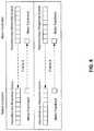
- FIG. 8is an illustration of how synchronous information and asynchronous information are communicated in a robotic surgical system of an embodiment.
- FIG. 9is a block diagram illustrating communication into and out of a node on a network of a robotic surgical system of an embodiment.
- FIG. 10is an illustration of a communications network of a robotic surgical system of an embodiment.
- FIG. 11is an illustration of a transmitter of a network component of a robotic surgical system of an embodiment.
- FIG. 12is an illustration of a receiver of a network component of a robotic surgical system of an embodiment.
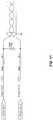
- FIG. 13is a diagram of a non-reversible equalized node-disconnectable ring wiring topology of any embodiment.
- the following embodimentsdescribe a robotic surgical system having a ring network for communicating information between a controller and nodes of one or more robotic arms.
- a communications protocolis described by which synchronous and asynchronous information can be communicated to and from the nodes of the robotic arms.
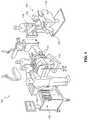
- FIG. 1is a diagram illustrating an example operating room environment with a surgical robotic system 100 , in accordance with aspects of the subject technology. It should be noted that this is merely an example for illustration purposes and other arrangements and components can be used. Accordingly, none of the details presented herein should be read into the claims unless explicitly recited therein.
- the surgical robotic system 100comprises a surgeon console 120 , a control tower 130 , and one or more surgical robotic arms 112 located at a surgical robotic platform 110 (e.g., a table or a bed etc.), where surgical tools with end effectors are attached to the distal ends of the robotic arms 112 for executing a surgical procedure.
- the robotic arms 112are shown as a table-mounted system, but in other configurations, the robotic arms may be mounted in a cart, ceiling or sidewall, or other suitable support surface.
- a usersuch as a surgeon or other operator, may use the user console 120 to remotely manipulate the robotic arms 112 and/or surgical instruments (e.g., tele-operation).
- the user console 120may be located in the same operating room as the robotic system 100 , as shown in FIG. 1 . In other environments, the user console 120 may be located in an adjacent or nearby room, or tele-operated from a remote location in a different building, city, or country.
- the user console 120may comprise a seat 122 , foot-operated controls 124 , one or more handheld user interface devices 126 , and at least one user display 128 configured to display, for example, a view of the surgical site inside a patient.
- a surgeon located in the seat 122 and viewing the user display 128may manipulate the foot-operated controls 124 and/or handheld user interface devices 126 to remotely control the robotic arms 112 and/or surgical instruments mounted to the distal ends of the arms.
- a usermay also operate the surgical robotic system 100 in an “over the bed” (OTB) mode, in which the user is at the patient's side and simultaneously manipulates a robotically-driven tool/end effector attached thereto (e.g., with a handheld user interface device 126 held in one hand) and a manual laparoscopic tool.
- OTBover the bed
- the user's left handmay be manipulating a handheld user interface device 126 to control a robotic surgical component
- the user's right handmay be manipulating a manual laparoscopic tool.
- the usermay perform both robotic-assisted minimally-invasive surgery (MIS) and manual laparoscopic surgery on a patient.
- MISrobotic-assisted minimally-invasive surgery
- the patientis prepped and draped in a sterile fashion to achieve anesthesia.
- Initial access to the surgical sitemay be performed manually with the robotic system 100 in a stowed configuration or withdrawn configuration to facilitate access to the surgical site. Once the access is completed, initial positioning and/or preparation of the robotic system may be performed.
- a surgeon in the user console 120may utilize the foot-operated controls 124 and/or user interface devices 126 to manipulate various end effectors and/or imaging systems to perform the surgery.
- Manual assistancemay also be provided at the procedure table by sterile-gowned personnel, who may perform tasks including but not limited to, retracting tissues or performing manual repositioning or tool exchange involving one or more robotic arms 112 .
- Non-sterile personnelmay also be present to assist the surgeon at the user console 120 .
- the robotic system 100 and/or user console 120may be configured or set in a state to facilitate one or more post-operative procedures, including but not limited to, robotic system 100 cleaning and/or sterilization, and/or healthcare record entry or printout, whether electronic or hard copy, such as via the user console 120 .
- the communication between the robotic platform 110 and the user console 120may be through the control tower 130 , which may translate user commands from the user console 120 to robotic control commands and transmit to the robotic platform 110 .
- the control tower 130may also transmit status and feedback from the robotic platform 110 back to the user console 120 .
- the connections between the robotic platform 110 , the user console 120 , and the control tower 130may be via wired and/or wireless connections, and may be proprietary and/or performed using any of a variety of data communication protocols. Any wired connections may be optionally built into the floor and/or walls or ceiling of the operating room.
- the surgical robotic system 100may provide video output to one or more displays, including displays within the operating room as well as remote displays accessible via the Internet or other networks.
- the video output or feedmay also be encrypted to ensure privacy and all or portions of the video output may be saved to a server or electronic healthcare record system.
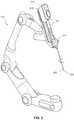
- FIG. 2is a diagram illustrating one exemplary design of a robotic arm, tool drive, and cannula loaded with a surgical tool, in accordance with aspects of the subject technology.
- the example surgical robotic arm 112may include a plurality of links and a plurality of actuated joint modules for actuating the plurality of links relative to one another.
- the joint modulesmay include various types, such as a pitch joint or a roll joint, which may substantially constrain the movement of the adjacent links around certain axes relative to others.
- a tool drive 210may be attached to the distal end of the robotic arm 112 .
- the tool drive 210may include a base or stage 212 and a cannula 214 coupled to the end of the tool drive 210 to receive and guide a surgical instrument 220 (e.g., endoscopes, staplers, etc.).
- the surgical instrument (or tool) 220may include a robotic wrist 222 and one or more end effectors 224 at the distal end of the tool.
- the plurality of the joint modules of the robotic arm 112can be actuated to position and orient the tool drive 210 , which actuates the robotic wrist 222 and the one or more end effectors 224 for robotic surgeries.
- the robotic arm 112also includes a plurality of nodes between adjacent links.
- a “node”can generally refer to a component that communicates with a controller of the robotic surgical system.
- a “node,” which will sometimes be referred to herein as a “joint module,”can be used for actuating one link of the robotic arm with respect to another (e.g., by using a motor to move a series of pulleys and a series of bands connecting the pulleys to facilitate four-bar linkage movement).
- the nodescan be used to articulate the various links in the robotic arm to manipulate the arm for a surgical procedure.
- nodesinclude, but are not limited to, one or more of the following: a single motor (e.g., a servomotor, a pivot-link motor, a joint motor, and a tool drive motor), a dual motor (e.g., with a differential gear drive to combine the individual motor outputs), a wireless tool interface (e.g., a tool wireless board), a force/torque sensor (e.g., an encoder that detects and provides signals characterizing at least one of force and torque multi-directionality applied to the robotic arm between the arm links/segments), an input/output board, a component that monitors power and/or communication links, or any other component that can receive/transmit data.
- a single motore.g., a servomotor, a pivot-link motor, a joint motor, and a tool drive motor
- a dual motore.g., with a differential gear drive to combine the individual motor outputs
- a wireless tool interfacee.g., a
- a nodecan also include various electronics, such as, but not limited to, a motor controller/driver, signal processors, and/or communications electronics on a circuit board.
- the nodescan be arranged in a ring network for communicating with an external controller.
- the control of the tool of the robotic armis done via a wireless tool interface, so as to provide electrical isolation between the tool and the other components of the robot for safety reasons.
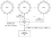
- FIG. 3is an illustration of a communications network of a robotic surgical system of an embodiment.
- the robotic surgical system of this embodimentcomprises a master controller 302 (sometimes referred to herein as “the robot controller” or “the data master” or simply “the controller”) in communication with a base controller 304 (sometimes referred to herein as “the second controller”), which is in communication with a plurality of robotic arms (ARM 1 -ARM n).
- the phrase “in communication with”could mean directly in communication with or indirectly in communication with through one or more components, which may or may not be shown or described herein.
- signals from the master controller 302 and base controller 304can be communicated to the nodes through wired connections bundled (e.g., in a wire harness) passing within the internal volumes of the arm links and joint modules of the robotic arm.
- FIG. 3shows a plurality of robotic arms
- a robotic surgical systemcan have only a single robotic arm, in which case the base controller 304 may not be used.
- the base controller 304is not used even when the robotic surgical system has a plurality of robotic arms.
- base controller 304is located in or near the patient table or bed (in such situations, the base controller 304 may be referred to as the table adapter controller (“TAC”)), and the master controller 302 is located in a communication tower separate from the patient bed.
- TACtable adapter controller
- a controllercan take the form of processing circuitry, a microprocessor or processor, and a computer-readable medium that stores computer-readable program code (e.g., firmware) executable by the (micro)processor, logic gates, switches, an application specific integrated circuit (ASIC), a programmable logic controller, and an embedded microcontroller, for example.
- a controllercan be configured with hardware and/or firmware to perform the various functions described below and shown in the flow diagrams. More generally, a controller (or module) can contain “circuitry” configured to perform various operations.
- circuitrycan refer to an instruction processor, such as a Central Processing Unit (CPU), microcontroller, or a microprocessor; or an Application Specific Integrated Circuit (ASIC), Programmable Logic Device (PLD), or Field Programmable Gate Array (FPGA); or a collection of discrete logic or other circuit components, including analog circuit components, digital circuit components or both; or any combination thereof.
- Circuitrymay include discrete interconnected hardware components or may be combined on a single integrated circuit die, distributed among multiple integrated circuit dies, or implemented in a Multiple Chip Module (MCM) of multiple integrated circuit dies in a common package, as examples. Accordingly, “circuitry” may store or access instructions for execution or may implement its functionality in hardware alone.
- the master controller 302can receive commands from the user console 100 ( FIG. 1 ) for manipulating the robotic arms and transmit those commands to the robotic arms.
- the nodes of each robotic armare arranged in a ring network.
- a ring networkrefers to a network topology in which each node connects to two other nodes, forming a single continuous pathway for signals through each node. Data travels from node to node, with each node along the way handling every packet. The propagation delay may be balanced, especially for the nodes at the distal end of the robotic arm. While FIG.
- each robotic armhas the same number of nodes, in other embodiments, at least one robotic arm has a different number of nodes than another robotic arm in the system.
- the ring networkcan be used for communicating both real-time and asynchronous information across the robotic arm network.
- the master controller 302is configured to communicate with the plurality of nodes in a given robotic arm using a multi-node message comprising a plurality of packets, each packet associated with a different node in the robotic arm.
- the arm multi-node messageis “multi-node” in that it can comprise data for all the nodes on that arm.
- a packetcan be associated with a node in any suitable way. For example, each packet can be addressed to a different node (e.g., using an identifier of the node) in the robotic arm and/or a node can be associated with a particular packet position in the message. Of course, these are just examples, and other associations can be used.
- Each packet in the multi-node messagecan be formatted in any suitable manner.
- a packet in the multi-node messagecan contain a header, a data payload, and a cyclic redundancy check (CRC) field.
- the packetcomprises a 16-bit packet framing constant, a 16-bit header, a fixed size (e.g., 128-bit or 224-bit) data payload including cyclic data (command or feedback), non-cyclic, and asynchronous data, and a 16-bit CRC field (e.g., CCITT).
- the packet framing constantcan be used to confirm the start of the packet.
- the payload data typecan be used to determine the format of the data payload (e.g., motor command, motor feedback, digital inputs, digital outputs, and force feedback).
- the channel IDcan be used by a node to confirm that the packet is intended to be delivered to that node. (In one embodiment, all the nodes across all the robotic arms have a unique channel ID.)
- the sequence fieldhelps a node determine whether the packet is new or not.
- the master controller 302increments the sequence number every time it sends out a new packet. If the master controller 302 gets interrupted, a node would see the same sequence number twice and know it is a duplicate packet.
- the CRC fieldcan cover the entire packet. In one embodiment, there are 80 packets per frame, with each frame being the same size. Of course, this is just one example, and other configurations can be used.
- the master controller 302can send the multi-node message directly to that arm. If multiple robotic arms are used, the master controller 302 can send all of the multi-node messages for all the arms together in a single message to the base controller 304 .
- the base controller 304can separate out each individual multi-node message from the single message and send each robotic arm its associated individual multi-node messages. For example, the base controller 304 can route messages to different robotic arms based on the message's offset in the overall combined message.
- the base controller 304can combine the received individual multi-node messages into a single returned merged message, and send the single returned merged message to the master controller 302 .
- the base controller 304can be configured to perform other functionality. For example, the base controller 304 can be used to move the robotic arms if the master controller 302 is not plugged into the system (e.g., allowing a nurse to move the robotic arms out of the way before draping the patient).
- the multi-node messageis used to communicate with the nodes in a given arm.
- a multi-node messageresembles a train with k boxcars, each node on the arm is assigned a boxcar, and passengers (data payload) get on and off their designated boxcar (i.e. full-duplex).
- the master controller 302can schedule one or more multi-node messages per cycle, and timing of each message can be optimized for optimal control of a distributed, digitally-sampled system.
- FIGS. 6A, 6B, and 6Cillustrate this communication flow.
- a nodecan comprise a field-programmable gate array (FPGA) that processes a multi-node message and is the physical interface between the node and the ring network.
- FPGAfield-programmable gate array
- the FPGA and the node controllercommunication via a serial peripheral interface (SPI) bus.
- SPIserial peripheral interface
- a nodecan have one or more additional components, such as a motor or sensor, connected to the node controller.
- the FPGAdecodes the multi-node message, looks for the synch token, and determines which packet in the message is associated with the node. It can then exchange data in a packet of the message. For example, as shown in FIGS. 6A and 6B , after the FPGA receives a message, it lets packets of the message pass through until the FPGA determines that a given packet is associated with its node. As shown in FIG. 6C , at that time, the FPGA can copy the data from the packet to a memory in the node controller and swap in other data stored in the memory of the node controller. The swapped-in data can be prepared in advance by the node controller, so it is ready to be sent once the appropriate packet arrives.
- the SPI bususes a protocol that does an automatic exchange
- the FPGAcan be programming with a slight delay to account of any synchronization issues in moving data out of and into a packet.
- the net effect of thisis that there is very little latency being introduced by each node because each node is receiving and responding to its packet at the same time as other nodes (i.e., each node is not receiving the whole multi-node message and then sending a response).
- all messages in the multi-node messageare passed through any node unaltered.
- a nodeis programmed to extract and replace only specific messages based on programmed start values relative to the frame sync token and a programmed message length. This is the analogy of a node being assigned a specific railroad car within the train (or rather two as there are two exchanges per frame). If there are n nodes, then there are 2n cars, and node x will be assigned cars x and x+n. In one embodiment, each node must exchange data at the allotted times, and failure to do so is a system fault (other implementations are possible). The node may be required to generate properly-formatted response packets even if no new data is available.
- the information to be communicated between the master controller 302 and the nodes of a robotic armcan be generally classified as “synchronous information” or “asynchronous information.”
- synchronous informationrefers to information that is intended to be processed upon receipt or within a certain timeframe (in real time)
- asynchronous informationrefers to information that can be stored and processed later (without the requirement that it be processed within a certain timeframe). So, as compared to synchronous information, there can be some latency between when asynchronous information is received and when it is processed.
- a command to actuate a motorcan be classified as synchronous information because a surgeon expects the robotic arm to move immediately after instructing the movement. As such, the command needs to be performed within a certain timeframe.
- a command that performs a low-priority maintenance functioncan be classified as asynchronous because the command does not need to be performed under a strict timeframe and can be performed whenever the node gets around to it.
- the timing of transmission between the master controller 302 and nodes of a robotic armis the same irrespective of whether the information being conveyed is synchronous information or asynchronous information.
- “synchronous” and “asynchronous”refers to an information type on the protocol level (i.e., whether or not a command needs to be processed in real time) and not to a timing requirement on the transport level, as both synchronous information and asynchronous information have the same transport synchronicity in this embodiment.
- the only difference between asynchronous and synchronous with respect to timingis that the latter has slightly lower latency due to placement within a frame.
- synchronous information and asynchronous informationcan be used and can take the form of commands (sometimes referred to as “requests”) and responses to commands.
- a synchronous commandcan be a command (i.e., a real-time motor control command) sent to a node that, when processed/executed by the node, actuates a motor to move a link in the robotic arm to a certain position or exert a specific torque.
- a response from the node to the synchronous commandcan be feedback to that command (e.g., a reading from a force/torque sensor in the node to confirm that the requested movement actually occurred).
- An asynchronous commandcan be a command sent to a node to request information from the node (e.g., identification of a surgical tool plugged into the robotic arm and information on its calibration and kinematic parameters), to request that a supervising/housekeeping function be performed (e.g., measuring temperatures and voltages of a node), or to request a change to one of the node's parameters.
- information from the nodee.g., identification of a surgical tool plugged into the robotic arm and information on its calibration and kinematic parameters
- a supervising/housekeeping functione.g., measuring temperatures and voltages of a node
- the timing of transmission between the master controller 302 and nodes of a robotic armis the same irrespective of whether the information being conveyed is synchronous information or asynchronous information.
- This real-time protocolcan be used to prescribe data transfer and data sequences between the master controller 302 and distributed motor controllers in the nodes of a robotic arm, for example.
- a lightweight, deterministic communication systemcan be tightly-integrated into the robotic platform, providing a robust and maintainable design.
- the communications protocol of this embodimentprovides real-time isochronous data communication of synchronous and asynchronous information using statically-allocated bandwidth and a simple schedule for sharing the bandwidth among different types of synchronous and asynchronous information.
- the communication protocoluses a constant cycle time to support hard, isochronous real-time data transfer between the master controller 302 and the plurality of nodes in the robotic arms.
- a cyclecan refer to the time from when the master controller 302 sends one or more multi-node messages to the ring network to when it receives those message(s) back from the ring network.
- the cycle timeis at a high frequency (e.g., 4 kHz) that can provide a motion control update rate with minimum latency and minimum jitter.
- payloads of the data packetsalternate between synchronous commands (e.g., motor control commands), asynchronous commands, responses to synchronous commands (e.g., sensor feedback), and responses to asynchronous commands.
- each category of datareceives a fixed fraction of the total bandwidth and is served with the same priority as other categories of data.
- cycle timeis constant (nominally, 250 microseconds) to support isochronous real-time data transfer with a hard deadline for communication, and two frames of data are exchanged each cycle.
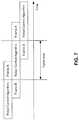
- FIG. 7In a given cycle, two frames of data are being transmitted between the master controller 302 and the nodes of the robotic arms.
- the master controller 302is executing a robot control algorithm to determine what commands to issue in the next command cycle. For example, looking at the center line in FIG.
- the master controller 302receives Frame B, which contains, in this example, the sensor data coming the motor controllers in all of the arms (i.e., responses to synchronous commands previously received by the nodes).
- Frame Bcontains, in this example, the sensor data coming the motor controllers in all of the arms (i.e., responses to synchronous commands previously received by the nodes).
- the master controller 302uses that sensor data to determine what command to send to the nodes in the next communication cycle. For example, if the sensor feedback shows that the robotic arm is not in the intended position, the master controller 302 can determine that another motor command is needed for that node to correct position.
- the master controller 302sends Frame A, which contains the commands determined in robot control algorithm in the previous cycle, to the nodes. Accordingly, this communication protocol uses pipelining and staging. As such, actions overlap in time, and there is certain amount of latency from when the feedback is received to when a new command is being sent out.
- FIG. 8shows how the two frames in a cycle can be used to communication synchronous information between the master controller 302 (called a “robot controller” in this example) and a node (a motor controller in this example).
- a robot controllere.g., motor commands
- FIG. 8shows how the two frames in a cycle can be used to communication synchronous information between the master controller 302 (called a “robot controller” in this example) and a node (a motor controller in this example).
- synchronous commandse.g., motor commands
- each nodee.g., motor controller
- a response to a synchronous command received in an earlier cycle(e.g., motor feedback in response to a motor control command) is sent from each node to the master/robot controller 302 , and asynchronous commands are sent from to the master/robot controller 302 to each node.
- asynchronous informationis interleaved with synchronous information. That is, for each frame, half the bandwidth is reserved for asynchronous information, and the other half of the bandwidth is reserved for synchronous information.
- FIG. 8shows that the master/robot controller 402 and a node (such as a motor controller) can have at least one memory to queue asynchronous commands (requests) and responses to be sent or processed.
- the queuescreate a buffer between what is happening in the asynchronous domain and what is happening on the real-time network.
- the master/robot controller 402can generate asynchronous housekeeping commands and store them in an asynchronous request queue until it has the opportunity to send them out to the nodes.
- the nodecan store an asynchronous housekeeping command in its queue and can get around to processing it when the node has a chance.
- the same queue process of the node and master/robot controller 302can occur when the node sends asynchronous responses to the master/robot controller 302 .
- synchronous commands/responsesare sent and acted upon in real time (i.e., they are not stored for transmittal and execution at a later time).
- the synchronous feedbackoccurs as late in a cycle (cycle N ⁇ 1) as possible, so that the robot control algorithm has the most up-to-date information as it is deciding (in cycle N) what the next synchronous command for the next cycle (N+1) should be.
- the synchronous commandis sent as early in cycle N+1 as possible, so the synchronous command can reach its node and be executed as soon as possible.
- any suitable physical layercan be used in the network.
- communication between the base controller 304 and the nodes on the robotic armuses a twisted-pair copper cable with pseudo-low-voltage differential signaling (LVDS) with additional low speed bi-directional common mode communication capabilities.
- LVDSpseudo-low-voltage differential signaling
- Communication between the master controller 302 and base controller 304can use a fiber optic link to achieve electrical isolation and low electromagnetic interference.
- a fiber optic linkthat is compatible with 1000 BASE-SX Ethernet is used.
- the linkdoes not carry Ethernet packets, but rather uses an Aurora interface with a 1.25 Gbps raw bit rate.
- This implementationcan provide advantages to other types of solutions. For example, a Controller Area Network may be too slow for certain requirements (e.g., 1M bit/s, 400 Hz cyclic rate), Ethernet is not suitable for real-time communication and is too big and heavy, and Ethernet for Control Automation Technology (EtherCAT), while supporting hard real-time applications, can be too big and expensive of a solution for some applications.
- EtherCATControl Automation Technology
- a high-speed busis desirable.
- ring topologies that are mechanically in a linear fashiontypically have short hops between nodes and a long return path, which decreases the maximum speed of the bus.
- the long returnis also more susceptible to noise.
- Having two connectors at each nodealso lends itself to reversing transmit and receive cables, which is not ideal.
- the typical wiring in a node-skipping configurationwould have wires not terminated at each node and replacing a node would require disassembling the two adjacent nodes.
- Equalizing the distance between each nodeallows for a higher bus speed and distributed noise.
- There are two visible communication cables at each nodeso knowing where each one connects is beneficial from a manufacturing and reducing troubleshooting point of view.
- the typical wiring in a node-skipping configurationwould have wires not terminated at each node. Replacing a node would require disassembling the two adjacent nodes as well. The terminations on the pass-through take care of this issue.
- each nodehas pass-through cable connectors and active cable connectors, which can be used to provide a node-skipping configuration. More specifically, in one embodiment, each node has two unique connector cables wired as crossovers (pin 1 wired to pin 4, pin 2 to pin 3, etc.). In one implementation, one cable is 4-pin to 4-pin, and the other is 5-pin to 5-pin. The use of these two different connectors prevents reversed connections.
- the 4-pin cableconnects the pass-through to receive signals from the adjacent nodes.
- the 5-pinconnects to the pass-through on the adjacent nodes. The pass-through is local to each node.
- each nodecomprises pass-through cable connectors and active cable connectors, so that the cables can be connected to the pass-through cable connectors and the active cable connectors to provide a node-skipping configuration.
- FIG. 13shows the increasing node number part of the ring, and arrows 1310 show transmit from Node 3 , passing through Node 4 , and received by Node 5 .
- Arrows 1320show the decreasing node number part of the ring where a transmit signal from Node 4 passes though Node 3 and is received by Node 2 . This can be thought of as an “out and back,” where half the nodes are active on the way out, and the remaining half are active on the way back.
- the loopbackcan either be local on the last node or through an external loopback cable on last node.
- the last nodeis only physically the last node in the linear layout; it is actually the n/2 node in the data flow layout.
- the first node or “master”can have both transmit and receive without a loopback.
- the base controller 304is the timing master for the communication with the nodes. This will be discussed in conjunction with FIG. 10 , which is another view of the ring network of an embodiment. As discussed above, the base controller 304 can separate out each individual multi-node message from the single message and send each robotic arm its associated individual multi-node messages simultaneously. In this embodiment, the base controller 304 is responsible for timing the communications to the nodes, so that simultaneous communication occurs. For example, as shown in FIG. 9 , between t 0 and t 1 , a first byte of each multi-node message is transmitted to each destination arm at the same time. Similarly, in the opposite direction, returned messages from the arms are assembled simultaneously into the master merged message.
- the base controller 304in addition to being responsible for separating out various multi-node arm messages, the base controller 304 is responsible for timing and scheduling the communications.
- the base controller 304is the “timing master” in that it can generate the 4 KHz frame and know when to send the messages to and receive the messages back from the robotic arms (e.g., so the messages are sent to/received from the nodes at the same time). For example, as shown in FIG. 10 , in one cycle (T), there can be t n slots (or “unit intervals (UI)”). At a 4 KHz cycle time, there can be 15,000 unit intervals (t 0 plus t n ) (assuming a 60 Mbps UI rate).
- the base controller 304can know exactly how many unit intervals get transferred per cycle and because communication on the network is isochronous communication, the base controller 304 can communicate the clock to the nodes on the network, so they can lock in their local clock to the master clock.
- each nodehas a phased-locked loop (PLL) that can be regenerated with the master clock.
- PLLphased-locked loop
- all the nodes in the networkcan run at the same frequency (e.g., by setting the integer fraction relationship to the 250 us frame period in this example), so they do not wander relative to one another.
- the PWMruns at 40 kHz, i.e., 10 times faster than the 250 us frame rate.
- FIGS. 11 and 12are illustrations of a transmitter and a receiver that can be used to communication on the physical network between the base controller 304 and the nodes on the robotic arm. It should be noted that this is just one example, and other configurations can be used.
- the transmitter in FIG. 11the transmitter in this embodiment is a “pseudo-LVDS” transmitter, in that the outgoing signal is compatible with LVDS, but it is not transmitted by a conventional LVDS transmitter. There are a few reasons for this. For example, LVDS is typically around 1.25 volts in common mode, going up or down a couple hundred millivolts to transmit 0 s and 1 s.
- the transmitter in this embodimentgenerates the same signal leveling through an external resistor divider.
- Driving one input high and the other lowresults in a signal that is LVDS compatible.
- Driving both inputs high or lowresults in low results in a common mode of 3.3 volts and 0 volts, respectively, which can be used to encode additional information (e.g., for power-up sequencing and for a secondary low-speed communication channel to initialize the ring network).
- Another reason for using this pseudo-LVDS transmitteris to provide a back-terminated transmission line, so if there is any noise on the line, it will die down in half its delay time and does not have to bounce back and forth.
- 3.3V LVCMOS outputsare wired through a resistor network to produce a back-terminated 100 Ohm differential drive into a shielded twisted pair.
- the driversare disabled and used as inputs to sense the common mode line voltage.
- the receiver in this embodimentcontains a high common mode range LVDS receiver for a high speed interface and a low pass filtered common mode voltage detector with hysteresis.
- the receivercan drive the common mode voltage (via CM_TALK) for upstream communication.
- the arm motor nodesadditionally contain circuitry that senses the common mode voltage to turn on the nodes after a power-up. This is meant to be used to stagger the in-rush currents inside the arm. Once powered, the enable is latched, and the node remains on. More specifically, the receiver in this embodiment has a LVDS receiver with high common mode rejection capabilities, which means it can differentiate the small differential signal in the presence of a large, common mode voltage.
- the top section of the receiver of this embodimentcan handle a situation where there is a noise spike (e.g., when a motor is activated and partially collapses the power supply) and the ground reference between the nodes swing arounds.
- the receiver of this embodimenthas common mode rejection capability to still be able to reliably detect low voltage differences in the presence of common mode.
- the bottom section of the receiver of this embodimentcan distinguish the common mode signal. So, if the transmitter is driving both input signals high or low, the bottom section of the receiver can detect using a comparator with a large amount of hysteresis for noise suppression. Above that comparator is a diode to power up the nodes in sequence to avoid large rush currents that may be difficult for the power distribution network to sustain. In particular, one embodiment isolates the power for each arm for safety reasons. So, when the arm is powered up, the voltage is there, but the individual regulators in the nodes are not actually turned on yet because common mode 0 is driven on the ring network (so, the voltage on EN 12V will be low).
- the node that is in the base of the armis first driven to common mode high, which will then go through that diode and turn on the regulator for the next node.
- One embodimentuses an automatic delay of about 5 milliseconds, as the delay can allow all in-rush currents to subside before the output driver is high. Rippling the power through the nodes in this way staggers the powering on of the nodes and distributes in-rush currents over a longer period of time and makes them smaller.
- the receiver of this embodimentalso has a CM Talk signal to provide the receiver with the capability to talk to the transmitter. So, the transmitters can be turned off and turned around as inputs for debugging and diagnostic purposes.
- communication between the base controller 304 and the nodesis through pseudo-LVDS using twisted-pair copper cable in one embodiment
- communication between the master controller 302 and base controller 304can use a fiber optic cable.
- the master controller 302has a computer with a PCIE card for communicating with the fiber optic cable.
- the master controller 302receives timing signals from the base controller 304 and is responsible for sending out synchronous and asynchronous commands to the base controller 304 for distribution to the nodes of the robotic arms.
- the synchronous feedbackoccurs as late in a cycle as possible, so that the robot control algorithm has the most up-to-date information as it is deciding what the next synchronous command should be.
- the synchronous commandis sent as early in a cycle as possible, so the synchronous command can reach its node and be executed as soon as possible. That is, this embodiment attempts to minimize the latency between when the master controller 302 receives feedback from the nodes and when it sends out the new real time commands to the nodes by phase-shifting the base controller 304 —arm communications with respect to the master controller 302 —base controller 204 communications.
- the master controller 302can be responsible for this timing.
- the protocol discussed abovedoes not have to occupy all of the bandwidth of the communication link. This allows running additional protocols (e.g., a secondary (“node management”) protocol used for initialization and health checks of the system) during the gaps in the ring network communications.
- a secondary (“node management”) protocolused for initialization and health checks of the system
Landscapes
- Engineering & Computer Science (AREA)
- Health & Medical Sciences (AREA)
- Life Sciences & Earth Sciences (AREA)
- Surgery (AREA)
- Robotics (AREA)
- Computer Networks & Wireless Communication (AREA)
- Signal Processing (AREA)
- Biomedical Technology (AREA)
- Nuclear Medicine, Radiotherapy & Molecular Imaging (AREA)
- Heart & Thoracic Surgery (AREA)
- Medical Informatics (AREA)
- Molecular Biology (AREA)
- Animal Behavior & Ethology (AREA)
- General Health & Medical Sciences (AREA)
- Public Health (AREA)
- Veterinary Medicine (AREA)
- Mechanical Engineering (AREA)
- Manipulator (AREA)
Abstract
Description
Claims (20)
Priority Applications (10)
| Application Number | Priority Date | Filing Date | Title |
|---|---|---|---|
| US15/707,503US10624707B2 (en) | 2017-09-18 | 2017-09-18 | Robotic surgical system and method for communicating synchronous and asynchronous information to and from nodes of a robotic arm |
| EP18856673.1AEP3684560A4 (en) | 2017-09-18 | 2018-07-19 | ROBOTIC SURGICAL SYSTEM AND METHOD FOR COMMUNICATING SYNCHRONOUS AND ASYNCHRONOUS INFORMATION TO AND FROM NODES OF A ROBOTIC ARM |
| CN201880060462.9ACN111278609B (en) | 2017-09-18 | 2018-07-19 | Robotic surgery systems and methods for communicating synchronous and asynchronous information to and from nodes of a robotic arm |
| CA3073200ACA3073200A1 (en) | 2017-09-18 | 2018-07-19 | Robotic surgical system and method for communicating synchronous and asynchronous information to and from nodes of a robotic arm |
| AU2018334392AAU2018334392B2 (en) | 2017-09-18 | 2018-07-19 | Robotic surgical system and method for communicating synchronous and asynchronous information to and from nodes of a robotic arm |
| KR1020207007287AKR102491737B1 (en) | 2017-09-18 | 2018-07-19 | Robotic surgical system and method for communicating synchronous and asynchronous information with nodes of a robotic arm |
| MA050183AMA50183A (en) | 2017-09-18 | 2018-07-19 | ROBOTIC SURGICAL SYSTEM AND METHOD FOR COMMUNICATING SYNCHRONOUS AND ASYNCHRONOUS INFORMATION TO AND FROM NODES OF A ROBOTIC ARM |
| PCT/US2018/042922WO2019055124A1 (en) | 2017-09-18 | 2018-07-19 | Robotic surgical system and method for communicating synchronous and asynchronous information to and from nodes of a robotic arm |
| US16/818,489US11266474B2 (en) | 2017-09-18 | 2020-03-13 | Robotic surgical system and method for communicating synchronous and asynchronous information to and from nodes of a robotic arm |
| US17/674,698US12295689B2 (en) | 2017-09-18 | 2022-02-17 | Robotic surgical system and method for communicating synchronous and asynchronous information to and from nodes of a robotic arm |
Applications Claiming Priority (1)
| Application Number | Priority Date | Filing Date | Title |
|---|---|---|---|
| US15/707,503US10624707B2 (en) | 2017-09-18 | 2017-09-18 | Robotic surgical system and method for communicating synchronous and asynchronous information to and from nodes of a robotic arm |
Related Child Applications (1)
| Application Number | Title | Priority Date | Filing Date |
|---|---|---|---|
| US16/818,489ContinuationUS11266474B2 (en) | 2017-09-18 | 2020-03-13 | Robotic surgical system and method for communicating synchronous and asynchronous information to and from nodes of a robotic arm |
Publications (2)
| Publication Number | Publication Date |
|---|---|
| US20190083190A1 US20190083190A1 (en) | 2019-03-21 |
| US10624707B2true US10624707B2 (en) | 2020-04-21 |
Family
ID=65719620
Family Applications (3)
| Application Number | Title | Priority Date | Filing Date |
|---|---|---|---|
| US15/707,503Active2038-02-07US10624707B2 (en) | 2017-09-18 | 2017-09-18 | Robotic surgical system and method for communicating synchronous and asynchronous information to and from nodes of a robotic arm |
| US16/818,489ActiveUS11266474B2 (en) | 2017-09-18 | 2020-03-13 | Robotic surgical system and method for communicating synchronous and asynchronous information to and from nodes of a robotic arm |
| US17/674,698Active2038-09-27US12295689B2 (en) | 2017-09-18 | 2022-02-17 | Robotic surgical system and method for communicating synchronous and asynchronous information to and from nodes of a robotic arm |
Family Applications After (2)
| Application Number | Title | Priority Date | Filing Date |
|---|---|---|---|
| US16/818,489ActiveUS11266474B2 (en) | 2017-09-18 | 2020-03-13 | Robotic surgical system and method for communicating synchronous and asynchronous information to and from nodes of a robotic arm |
| US17/674,698Active2038-09-27US12295689B2 (en) | 2017-09-18 | 2022-02-17 | Robotic surgical system and method for communicating synchronous and asynchronous information to and from nodes of a robotic arm |
Country Status (8)
| Country | Link |
|---|---|
| US (3) | US10624707B2 (en) |
| EP (1) | EP3684560A4 (en) |
| KR (1) | KR102491737B1 (en) |
| CN (1) | CN111278609B (en) |
| AU (1) | AU2018334392B2 (en) |
| CA (1) | CA3073200A1 (en) |
| MA (1) | MA50183A (en) |
| WO (1) | WO2019055124A1 (en) |
Families Citing this family (132)
| Publication number | Priority date | Publication date | Assignee | Title |
|---|---|---|---|---|
| US11871901B2 (en) | 2012-05-20 | 2024-01-16 | Cilag Gmbh International | Method for situational awareness for surgical network or surgical network connected device capable of adjusting function based on a sensed situation or usage |
| US11504192B2 (en) | 2014-10-30 | 2022-11-22 | Cilag Gmbh International | Method of hub communication with surgical instrument systems |
| US10966720B2 (en) | 2017-09-01 | 2021-04-06 | RevMedica, Inc. | Surgical stapler with removable power pack |
| US10695060B2 (en) | 2017-09-01 | 2020-06-30 | RevMedica, Inc. | Loadable power pack for surgical instruments |
| US11331099B2 (en) | 2017-09-01 | 2022-05-17 | Rev Medica, Inc. | Surgical stapler with removable power pack and interchangeable battery pack |
| US10624707B2 (en) | 2017-09-18 | 2020-04-21 | Verb Surgical Inc. | Robotic surgical system and method for communicating synchronous and asynchronous information to and from nodes of a robotic arm |
| US10779901B2 (en) | 2017-09-18 | 2020-09-22 | Verb Surgical Inc. | Robotic surgical system having a communication network of a ring topology and method for use therewith |
| US11801098B2 (en) | 2017-10-30 | 2023-10-31 | Cilag Gmbh International | Method of hub communication with surgical instrument systems |
| US11317919B2 (en) | 2017-10-30 | 2022-05-03 | Cilag Gmbh International | Clip applier comprising a clip crimping system |
| US11026687B2 (en) | 2017-10-30 | 2021-06-08 | Cilag Gmbh International | Clip applier comprising clip advancing systems |
| US11911045B2 (en) | 2017-10-30 | 2024-02-27 | Cllag GmbH International | Method for operating a powered articulating multi-clip applier |
| US11291510B2 (en) | 2017-10-30 | 2022-04-05 | Cilag Gmbh International | Method of hub communication with surgical instrument systems |
| US11311342B2 (en) | 2017-10-30 | 2022-04-26 | Cilag Gmbh International | Method for communicating with surgical instrument systems |
| US11510741B2 (en) | 2017-10-30 | 2022-11-29 | Cilag Gmbh International | Method for producing a surgical instrument comprising a smart electrical system |
| US11925373B2 (en) | 2017-10-30 | 2024-03-12 | Cilag Gmbh International | Surgical suturing instrument comprising a non-circular needle |
| US11564756B2 (en) | 2017-10-30 | 2023-01-31 | Cilag Gmbh International | Method of hub communication with surgical instrument systems |
| US11896322B2 (en) | 2017-12-28 | 2024-02-13 | Cilag Gmbh International | Sensing the patient position and contact utilizing the mono-polar return pad electrode to provide situational awareness to the hub |
| US11424027B2 (en) | 2017-12-28 | 2022-08-23 | Cilag Gmbh International | Method for operating surgical instrument systems |
| US20190201112A1 (en) | 2017-12-28 | 2019-07-04 | Ethicon Llc | Computer implemented interactive surgical systems |
| US11744604B2 (en) | 2017-12-28 | 2023-09-05 | Cilag Gmbh International | Surgical instrument with a hardware-only control circuit |
| US11389164B2 (en) | 2017-12-28 | 2022-07-19 | Cilag Gmbh International | Method of using reinforced flexible circuits with multiple sensors to optimize performance of radio frequency devices |
| US11559308B2 (en) | 2017-12-28 | 2023-01-24 | Cilag Gmbh International | Method for smart energy device infrastructure |
| US11304763B2 (en) | 2017-12-28 | 2022-04-19 | Cilag Gmbh International | Image capturing of the areas outside the abdomen to improve placement and control of a surgical device in use |
| US11026751B2 (en) | 2017-12-28 | 2021-06-08 | Cilag Gmbh International | Display of alignment of staple cartridge to prior linear staple line |
| US11786245B2 (en) | 2017-12-28 | 2023-10-17 | Cilag Gmbh International | Surgical systems with prioritized data transmission capabilities |
| US11013563B2 (en) | 2017-12-28 | 2021-05-25 | Ethicon Llc | Drive arrangements for robot-assisted surgical platforms |
| US11308075B2 (en) | 2017-12-28 | 2022-04-19 | Cilag Gmbh International | Surgical network, instrument, and cloud responses based on validation of received dataset and authentication of its source and integrity |
| US11633237B2 (en) | 2017-12-28 | 2023-04-25 | Cilag Gmbh International | Usage and technique analysis of surgeon / staff performance against a baseline to optimize device utilization and performance for both current and future procedures |
| US20190201142A1 (en) | 2017-12-28 | 2019-07-04 | Ethicon Llc | Automatic tool adjustments for robot-assisted surgical platforms |
| US11284936B2 (en) | 2017-12-28 | 2022-03-29 | Cilag Gmbh International | Surgical instrument having a flexible electrode |
| US10892995B2 (en) | 2017-12-28 | 2021-01-12 | Ethicon Llc | Surgical network determination of prioritization of communication, interaction, or processing based on system or device needs |
| US11179175B2 (en) | 2017-12-28 | 2021-11-23 | Cilag Gmbh International | Controlling an ultrasonic surgical instrument according to tissue location |
| US11696760B2 (en) | 2017-12-28 | 2023-07-11 | Cilag Gmbh International | Safety systems for smart powered surgical stapling |
| US11304745B2 (en) | 2017-12-28 | 2022-04-19 | Cilag Gmbh International | Surgical evacuation sensing and display |
| US11464535B2 (en) | 2017-12-28 | 2022-10-11 | Cilag Gmbh International | Detection of end effector emersion in liquid |
| US11304699B2 (en) | 2017-12-28 | 2022-04-19 | Cilag Gmbh International | Method for adaptive control schemes for surgical network control and interaction |
| US11234756B2 (en) | 2017-12-28 | 2022-02-01 | Cilag Gmbh International | Powered surgical tool with predefined adjustable control algorithm for controlling end effector parameter |
| US11202570B2 (en) | 2017-12-28 | 2021-12-21 | Cilag Gmbh International | Communication hub and storage device for storing parameters and status of a surgical device to be shared with cloud based analytics systems |
| US11076921B2 (en) | 2017-12-28 | 2021-08-03 | Cilag Gmbh International | Adaptive control program updates for surgical hubs |
| US11324557B2 (en) | 2017-12-28 | 2022-05-10 | Cilag Gmbh International | Surgical instrument with a sensing array |
| US11659023B2 (en) | 2017-12-28 | 2023-05-23 | Cilag Gmbh International | Method of hub communication |
| WO2019133144A1 (en) | 2017-12-28 | 2019-07-04 | Ethicon Llc | Detection and escalation of security responses of surgical instruments to increasing severity threats |
| US11571234B2 (en) | 2017-12-28 | 2023-02-07 | Cilag Gmbh International | Temperature control of ultrasonic end effector and control system therefor |
| US20190201090A1 (en) | 2017-12-28 | 2019-07-04 | Ethicon Llc | Capacitive coupled return path pad with separable array elements |
| US11291495B2 (en) | 2017-12-28 | 2022-04-05 | Cilag Gmbh International | Interruption of energy due to inadvertent capacitive coupling |
| US11786251B2 (en) | 2017-12-28 | 2023-10-17 | Cilag Gmbh International | Method for adaptive control schemes for surgical network control and interaction |
| US11376002B2 (en) | 2017-12-28 | 2022-07-05 | Cilag Gmbh International | Surgical instrument cartridge sensor assemblies |
| US11464559B2 (en) | 2017-12-28 | 2022-10-11 | Cilag Gmbh International | Estimating state of ultrasonic end effector and control system therefor |
| US20190206569A1 (en) | 2017-12-28 | 2019-07-04 | Ethicon Llc | Method of cloud based data analytics for use with the hub |
| US11166772B2 (en) | 2017-12-28 | 2021-11-09 | Cilag Gmbh International | Surgical hub coordination of control and communication of operating room devices |
| US11903601B2 (en) | 2017-12-28 | 2024-02-20 | Cilag Gmbh International | Surgical instrument comprising a plurality of drive systems |
| US11529187B2 (en) | 2017-12-28 | 2022-12-20 | Cilag Gmbh International | Surgical evacuation sensor arrangements |
| US11602393B2 (en) | 2017-12-28 | 2023-03-14 | Cilag Gmbh International | Surgical evacuation sensing and generator control |
| US20190201039A1 (en) | 2017-12-28 | 2019-07-04 | Ethicon Llc | Situational awareness of electrosurgical systems |
| US11832899B2 (en) | 2017-12-28 | 2023-12-05 | Cilag Gmbh International | Surgical systems with autonomously adjustable control programs |
| US11317937B2 (en) | 2018-03-08 | 2022-05-03 | Cilag Gmbh International | Determining the state of an ultrasonic end effector |
| US11540855B2 (en) | 2017-12-28 | 2023-01-03 | Cilag Gmbh International | Controlling activation of an ultrasonic surgical instrument according to the presence of tissue |
| US12396806B2 (en) | 2017-12-28 | 2025-08-26 | Cilag Gmbh International | Adjustment of a surgical device function based on situational awareness |
| US11857152B2 (en) | 2017-12-28 | 2024-01-02 | Cilag Gmbh International | Surgical hub spatial awareness to determine devices in operating theater |
| US11364075B2 (en) | 2017-12-28 | 2022-06-21 | Cilag Gmbh International | Radio frequency energy device for delivering combined electrical signals |
| US11832840B2 (en) | 2017-12-28 | 2023-12-05 | Cilag Gmbh International | Surgical instrument having a flexible circuit |
| US11419667B2 (en) | 2017-12-28 | 2022-08-23 | Cilag Gmbh International | Ultrasonic energy device which varies pressure applied by clamp arm to provide threshold control pressure at a cut progression location |
| US11666331B2 (en) | 2017-12-28 | 2023-06-06 | Cilag Gmbh International | Systems for detecting proximity of surgical end effector to cancerous tissue |
| US11410259B2 (en) | 2017-12-28 | 2022-08-09 | Cilag Gmbh International | Adaptive control program updates for surgical devices |
| US12376855B2 (en) | 2017-12-28 | 2025-08-05 | Cilag Gmbh International | Safety systems for smart powered surgical stapling |
| US12127729B2 (en) | 2017-12-28 | 2024-10-29 | Cilag Gmbh International | Method for smoke evacuation for surgical hub |
| US11253315B2 (en) | 2017-12-28 | 2022-02-22 | Cilag Gmbh International | Increasing radio frequency to create pad-less monopolar loop |
| US11132462B2 (en) | 2017-12-28 | 2021-09-28 | Cilag Gmbh International | Data stripping method to interrogate patient records and create anonymized record |
| US12062442B2 (en) | 2017-12-28 | 2024-08-13 | Cilag Gmbh International | Method for operating surgical instrument systems |
| US11419630B2 (en)* | 2017-12-28 | 2022-08-23 | Cilag Gmbh International | Surgical system distributed processing |
| US11266468B2 (en) | 2017-12-28 | 2022-03-08 | Cilag Gmbh International | Cooperative utilization of data derived from secondary sources by intelligent surgical hubs |
| US11864728B2 (en) | 2017-12-28 | 2024-01-09 | Cilag Gmbh International | Characterization of tissue irregularities through the use of mono-chromatic light refractivity |
| US12096916B2 (en) | 2017-12-28 | 2024-09-24 | Cilag Gmbh International | Method of sensing particulate from smoke evacuated from a patient, adjusting the pump speed based on the sensed information, and communicating the functional parameters of the system to the hub |
| US10918310B2 (en) | 2018-01-03 | 2021-02-16 | Biosense Webster (Israel) Ltd. | Fast anatomical mapping (FAM) using volume filling |
| US11937769B2 (en) | 2017-12-28 | 2024-03-26 | Cilag Gmbh International | Method of hub communication, processing, storage and display |
| US10758310B2 (en) | 2017-12-28 | 2020-09-01 | Ethicon Llc | Wireless pairing of a surgical device with another device within a sterile surgical field based on the usage and situational awareness of devices |
| US11311306B2 (en) | 2017-12-28 | 2022-04-26 | Cilag Gmbh International | Surgical systems for detecting end effector tissue distribution irregularities |
| US11998193B2 (en) | 2017-12-28 | 2024-06-04 | Cilag Gmbh International | Method for usage of the shroud as an aspect of sensing or controlling a powered surgical device, and a control algorithm to adjust its default operation |
| US11432885B2 (en) | 2017-12-28 | 2022-09-06 | Cilag Gmbh International | Sensing arrangements for robot-assisted surgical platforms |
| US11818052B2 (en) | 2017-12-28 | 2023-11-14 | Cilag Gmbh International | Surgical network determination of prioritization of communication, interaction, or processing based on system or device needs |
| US11969142B2 (en) | 2017-12-28 | 2024-04-30 | Cilag Gmbh International | Method of compressing tissue within a stapling device and simultaneously displaying the location of the tissue within the jaws |
| US11559307B2 (en) | 2017-12-28 | 2023-01-24 | Cilag Gmbh International | Method of robotic hub communication, detection, and control |
| US11109866B2 (en) | 2017-12-28 | 2021-09-07 | Cilag Gmbh International | Method for circular stapler control algorithm adjustment based on situational awareness |
| US11304720B2 (en) | 2017-12-28 | 2022-04-19 | Cilag Gmbh International | Activation of energy devices |
| US11576677B2 (en) | 2017-12-28 | 2023-02-14 | Cilag Gmbh International | Method of hub communication, processing, display, and cloud analytics |
| US11896443B2 (en) | 2017-12-28 | 2024-02-13 | Cilag Gmbh International | Control of a surgical system through a surgical barrier |
| US11423007B2 (en) | 2017-12-28 | 2022-08-23 | Cilag Gmbh International | Adjustment of device control programs based on stratified contextual data in addition to the data |
| US11257589B2 (en) | 2017-12-28 | 2022-02-22 | Cilag Gmbh International | Real-time analysis of comprehensive cost of all instrumentation used in surgery utilizing data fluidity to track instruments through stocking and in-house processes |
| US11589888B2 (en) | 2017-12-28 | 2023-02-28 | Cilag Gmbh International | Method for controlling smart energy devices |
| US11446052B2 (en) | 2017-12-28 | 2022-09-20 | Cilag Gmbh International | Variation of radio frequency and ultrasonic power level in cooperation with varying clamp arm pressure to achieve predefined heat flux or power applied to tissue |
| US11678881B2 (en) | 2017-12-28 | 2023-06-20 | Cilag Gmbh International | Spatial awareness of surgical hubs in operating rooms |
| US11969216B2 (en) | 2017-12-28 | 2024-04-30 | Cilag Gmbh International | Surgical network recommendations from real time analysis of procedure variables against a baseline highlighting differences from the optimal solution |
| US11278281B2 (en) | 2017-12-28 | 2022-03-22 | Cilag Gmbh International | Interactive surgical system |
| US11612444B2 (en) | 2017-12-28 | 2023-03-28 | Cilag Gmbh International | Adjustment of a surgical device function based on situational awareness |
| GB2571566B (en)* | 2018-03-01 | 2022-03-16 | Cmr Surgical Ltd | Electrosurgical connection unit |
| US12303159B2 (en) | 2018-03-08 | 2025-05-20 | Cilag Gmbh International | Methods for estimating and controlling state of ultrasonic end effector |
| US11986233B2 (en) | 2018-03-08 | 2024-05-21 | Cilag Gmbh International | Adjustment of complex impedance to compensate for lost power in an articulating ultrasonic device |
| US11534196B2 (en) | 2018-03-08 | 2022-12-27 | Cilag Gmbh International | Using spectroscopy to determine device use state in combo instrument |
| US11259830B2 (en) | 2018-03-08 | 2022-03-01 | Cilag Gmbh International | Methods for controlling temperature in ultrasonic device |
| US11278280B2 (en) | 2018-03-28 | 2022-03-22 | Cilag Gmbh International | Surgical instrument comprising a jaw closure lockout |
| US11213294B2 (en) | 2018-03-28 | 2022-01-04 | Cilag Gmbh International | Surgical instrument comprising co-operating lockout features |
| US11090047B2 (en) | 2018-03-28 | 2021-08-17 | Cilag Gmbh International | Surgical instrument comprising an adaptive control system |
| US11589865B2 (en) | 2018-03-28 | 2023-02-28 | Cilag Gmbh International | Methods for controlling a powered surgical stapler that has separate rotary closure and firing systems |
| US11471156B2 (en) | 2018-03-28 | 2022-10-18 | Cilag Gmbh International | Surgical stapling devices with improved rotary driven closure systems |
| US10933526B2 (en)* | 2018-04-23 | 2021-03-02 | General Electric Company | Method and robotic system for manipulating instruments |
| US11317915B2 (en) | 2019-02-19 | 2022-05-03 | Cilag Gmbh International | Universal cartridge based key feature that unlocks multiple lockout arrangements in different surgical staplers |
| US11357503B2 (en) | 2019-02-19 | 2022-06-14 | Cilag Gmbh International | Staple cartridge retainers with frangible retention features and methods of using same |
| US11369377B2 (en) | 2019-02-19 | 2022-06-28 | Cilag Gmbh International | Surgical stapling assembly with cartridge based retainer configured to unlock a firing lockout |
| US11331100B2 (en) | 2019-02-19 | 2022-05-17 | Cilag Gmbh International | Staple cartridge retainer system with authentication keys |
| US11464511B2 (en) | 2019-02-19 | 2022-10-11 | Cilag Gmbh International | Surgical staple cartridges with movable authentication key arrangements |
| US11318618B2 (en)* | 2019-04-05 | 2022-05-03 | Verb Surgical Inc. | Robotic surgical system and method for handling real-time and non-real-time traffic |
| USD964564S1 (en) | 2019-06-25 | 2022-09-20 | Cilag Gmbh International | Surgical staple cartridge retainer with a closure system authentication key |
| USD952144S1 (en) | 2019-06-25 | 2022-05-17 | Cilag Gmbh International | Surgical staple cartridge retainer with firing system authentication key |
| USD950728S1 (en) | 2019-06-25 | 2022-05-03 | Cilag Gmbh International | Surgical staple cartridge |
| US12279771B2 (en) | 2019-07-19 | 2025-04-22 | RevMedica, Inc. | Power pack for activating surgical instruments and providing user feedback |
| EP3998960A4 (en) | 2019-07-19 | 2022-12-14 | Revmedica, Inc. | Surgical stapler with removable power pack |
| US12290257B2 (en) | 2019-07-19 | 2025-05-06 | RevMedica, Inc. | Surgical clip applier with removable power pack |
| US12357307B2 (en) | 2022-05-13 | 2025-07-15 | RevMedica, Inc. | Power pack for activating surgical instruments and providing user feedback |
| US12279770B2 (en) | 2019-07-19 | 2025-04-22 | RevMedica, Inc. | Power pack for activating surgical instruments and providing user feedback |
| US11419686B2 (en) | 2019-09-13 | 2022-08-23 | Verb Surgical Inc. | Trajectory representation in design and testing of a surgical robot |
| US11690674B2 (en)* | 2020-04-03 | 2023-07-04 | Verb Surgical Inc. | Mobile virtual reality system for surgical robotic systems |
| GB2598387B (en)* | 2020-08-31 | 2025-02-05 | Cmr Surgical Ltd | Control system for surgical robot system wtih safety device |
| US20250120777A1 (en)* | 2020-08-31 | 2025-04-17 | Cmr Surgical Limited | Control system for surgical robot system with safety device |
| GB2598388B (en)* | 2020-08-31 | 2024-11-13 | Cmr Surgical Ltd | Control system for surgical robot system with safety monitor |
| WO2022070000A1 (en)* | 2020-09-30 | 2022-04-07 | Auris Health, Inc. | System and method of controlling motion of kinematic chains |
| CN112186077B (en)* | 2020-10-20 | 2022-12-16 | 湖南红太阳光电科技有限公司 | An intelligent manufacturing control system for a solar cell plant |
| US12178535B2 (en) | 2021-03-01 | 2024-12-31 | RevMedica, Inc. | Power pack for activating surgical instruments |
| CN114102602B (en)* | 2021-12-08 | 2022-06-03 | 山东省地质矿产勘查开发局第一地质大队(山东省第一地质矿产勘查院) | Method and system for remotely controlling geological mapping self-walking robot |
| JP2023127414A (en)* | 2022-03-01 | 2023-09-13 | 本田技研工業株式会社 | robot |
| CN115502975A (en)* | 2022-10-09 | 2022-12-23 | 上海节卡机器人科技有限公司 | A robot scheduling method, device, electronic equipment and storage medium |
| CN116192915A (en)* | 2022-12-30 | 2023-05-30 | 哈尔滨思哲睿智能医疗设备股份有限公司 | Communication method, computer equipment, and storage medium for robotic surgery system |
| CN118802991B (en)* | 2024-09-14 | 2024-12-31 | 深圳市精锋医疗科技股份有限公司 | Bandwidth allocation method, system and storage medium for remote surgical robot |
Citations (19)
| Publication number | Priority date | Publication date | Assignee | Title |
|---|---|---|---|---|
| US20060074525A1 (en) | 2004-10-01 | 2006-04-06 | Eric Close | Network architecture for remote robot with interchangeable tools |
| US20070112463A1 (en) | 2005-11-17 | 2007-05-17 | Roh Myung C | Robot server for controlling robot, system having the same for providing content, and method thereof |
| US20070150631A1 (en)* | 2005-12-22 | 2007-06-28 | Intuitive Surgical Inc. | Multi-priority messaging |
| US20080144526A1 (en) | 2006-12-13 | 2008-06-19 | Honeywell International Inc. | Methods for expedited start-up and clique aggregation using self-checking node pairs on a ring network |
| US20100145521A1 (en) | 2005-12-20 | 2010-06-10 | Intuitive Surgical, Inc. | Robotic surgical system with joint motion controller adapted to reduce instrument tip vibrations |
| US20100234857A1 (en)* | 1998-11-20 | 2010-09-16 | Intuitve Surgical Operations, Inc. | Medical robotic system with operatively couplable simulator unit for surgeon training |
| US20110112696A1 (en) | 2006-07-07 | 2011-05-12 | Ofer Yodfat | Fluid Delivery Device and Methods of Its Operation |
| US8072999B1 (en)* | 2007-05-08 | 2011-12-06 | Motion Engineering Inc. | Method and system for removing and returning nodes in a synchronous network |
| US20120039162A1 (en) | 2005-12-22 | 2012-02-16 | Intuitive Surgical, Inc. | Synchronous Data Communication |
| US20130245375A1 (en) | 2005-06-06 | 2013-09-19 | The Johns Hopkins University c/o John Hopkins Technology Transfer | Interactive user interfaces for robotic minimally invasive surgical systems |
| US20130345875A1 (en) | 2012-06-21 | 2013-12-26 | Rethink Robotics, Inc. | Training and operating industrial robots |
| US20140210520A1 (en) | 2013-01-29 | 2014-07-31 | Raytheon Company | Low power low voltage differential driver |
| US20150078746A1 (en) | 2013-07-11 | 2015-03-19 | Plexxi Inc. | Network node connection configuration |
| US20160338676A1 (en) | 1999-06-22 | 2016-11-24 | Noah Berger | Ultrasound probe with integrated electronics |
| US9544258B2 (en) | 2014-06-27 | 2017-01-10 | Beckhoff Automation Gmbh | Network, head subscriber and data transmission method |
| US20170097631A1 (en) | 2014-05-21 | 2017-04-06 | Bot & Dolly, Llc | Systems and Methods for Time-Based Parallel Robotic Operation |
| US20180303482A1 (en) | 2006-01-31 | 2018-10-25 | Ethicon Llc | Accessing data stored in a memory of a surgical instrument |
| US20190083186A1 (en) | 2017-09-18 | 2019-03-21 | Verb Surgical Inc. | Robotic Surgical System Having a Communication Network of a Ring Toplogy and Method for Use Therewith |
| US20190083190A1 (en) | 2017-09-18 | 2019-03-21 | Verb Surgical Inc. | Robotic Surgical System and Method for Communicating Synchronous and Asynchronous Information to and From Nodes of a Robotic Arm |
Family Cites Families (22)
| Publication number | Priority date | Publication date | Assignee | Title |
|---|---|---|---|---|
| CA2255418C (en)* | 1998-12-07 | 2003-01-21 | Pmc-Sierra Ltd. | Ring interface and ring network bus flow control system |
| JP4273669B2 (en) | 2001-02-28 | 2009-06-03 | 沖電気工業株式会社 | Node information management system and node |
| DE10304637A1 (en)* | 2003-02-04 | 2004-08-19 | Elektro Beckhoff Gmbh Unternehmensbereich Industrie Elektronik | Network coupler, network and data processing method for Ethernet telegrams |
| JP2007174644A (en)* | 2005-12-22 | 2007-07-05 | Intuitive Surgical Inc | Synchronized data communication |
| US7756036B2 (en)* | 2005-12-22 | 2010-07-13 | Intuitive Surgical Operations, Inc. | Synchronous data communication |
| KR101041375B1 (en) | 2009-03-23 | 2011-06-15 | 한국과학기술연구원 | Network converter, robot control system and method using the same |
| US8320282B2 (en) | 2009-07-30 | 2012-11-27 | Calix, Inc. | Automatic control node selection in ring networks |
| US8120935B2 (en) | 2011-03-29 | 2012-02-21 | American Superconductor Corporation | Power converter with dual ring network control |
| CN102946631B (en)* | 2012-11-23 | 2016-05-04 | 北京邮电大学 | A kind of based on beacon frame synchronously with the MAC node layer dispatching method of communicating by letter asynchronous |
| US9225556B2 (en)* | 2013-06-07 | 2015-12-29 | Broadcom Corporation | Multiplexed packet local area networking using an Ethernet physical layer device |
| KR102463600B1 (en) | 2013-08-09 | 2022-11-07 | 인튜어티브 서지컬 오퍼레이션즈 인코포레이티드 | Medical robotic system with remote current controller for controlling a plurality of distally housed motors |
| KR102299245B1 (en)* | 2013-08-16 | 2021-09-08 | 인튜어티브 서지컬 오퍼레이션즈 인코포레이티드 | System and method for coordinated motion among heterogeneous devices |
| US10164793B2 (en)* | 2013-10-15 | 2018-12-25 | National Instruments Corporation | System and method for interoperability between multiple networks |
| US9446517B2 (en) | 2013-10-17 | 2016-09-20 | Intuitive Surgical Operations, Inc. | Fault reaction, fault isolation, and graceful degradation in a robotic system |
| US10277417B2 (en) | 2014-03-04 | 2019-04-30 | Omron Corporation | Control system, control apparatus and control method with input-only communication frame |
| KR101632034B1 (en) | 2014-11-06 | 2016-07-01 | (주)미래컴퍼니 | Surgical Robot System and Method for Controlling Surgical Robot System |
| US10788228B2 (en)* | 2015-07-08 | 2020-09-29 | Berner International Corporation | Enhanced techniques for air curtain control |
| CN108025445A (en) | 2015-07-23 | 2018-05-11 | 斯里国际 | Robots arm and robotic surgical system |
| DE102015010969A1 (en) | 2015-08-26 | 2017-03-02 | Airbus Defence and Space GmbH | Network module for sending and / or receiving data packets from a network device and method |
| DE102016107940A1 (en) | 2016-04-28 | 2017-11-02 | Balluff Gmbh | A method for network initialization of a network for the radio location of objects within a limited space |
| CN106041929B (en)* | 2016-06-24 | 2018-03-30 | 南京工程学院 | A kind of control method for six-DOF robot |
| EP3745984B1 (en)* | 2018-02-02 | 2022-08-31 | Covidien LP | Surgical robotic system including synchronous and asynchronous networks and a method employing the same |
- 2017
- 2017-09-18USUS15/707,503patent/US10624707B2/enactiveActive
- 2018
- 2018-07-19AUAU2018334392Apatent/AU2018334392B2/enactiveActive
- 2018-07-19KRKR1020207007287Apatent/KR102491737B1/enactiveActive
- 2018-07-19CACA3073200Apatent/CA3073200A1/enactivePending
- 2018-07-19WOPCT/US2018/042922patent/WO2019055124A1/ennot_activeCeased
- 2018-07-19EPEP18856673.1Apatent/EP3684560A4/enactivePending
- 2018-07-19MAMA050183Apatent/MA50183A/enunknown
- 2018-07-19CNCN201880060462.9Apatent/CN111278609B/enactiveActive
- 2020
- 2020-03-13USUS16/818,489patent/US11266474B2/enactiveActive
- 2022
- 2022-02-17USUS17/674,698patent/US12295689B2/enactiveActive
Patent Citations (20)
| Publication number | Priority date | Publication date | Assignee | Title |
|---|---|---|---|---|
| US20100234857A1 (en)* | 1998-11-20 | 2010-09-16 | Intuitve Surgical Operations, Inc. | Medical robotic system with operatively couplable simulator unit for surgeon training |
| US20160338676A1 (en) | 1999-06-22 | 2016-11-24 | Noah Berger | Ultrasound probe with integrated electronics |
| US20060074525A1 (en) | 2004-10-01 | 2006-04-06 | Eric Close | Network architecture for remote robot with interchangeable tools |
| US20130245375A1 (en) | 2005-06-06 | 2013-09-19 | The Johns Hopkins University c/o John Hopkins Technology Transfer | Interactive user interfaces for robotic minimally invasive surgical systems |
| US20070112463A1 (en) | 2005-11-17 | 2007-05-17 | Roh Myung C | Robot server for controlling robot, system having the same for providing content, and method thereof |
| US20100145521A1 (en) | 2005-12-20 | 2010-06-10 | Intuitive Surgical, Inc. | Robotic surgical system with joint motion controller adapted to reduce instrument tip vibrations |
| US7757028B2 (en) | 2005-12-22 | 2010-07-13 | Intuitive Surgical Operations, Inc. | Multi-priority messaging |
| US20120039162A1 (en) | 2005-12-22 | 2012-02-16 | Intuitive Surgical, Inc. | Synchronous Data Communication |
| US20070150631A1 (en)* | 2005-12-22 | 2007-06-28 | Intuitive Surgical Inc. | Multi-priority messaging |
| US20180303482A1 (en) | 2006-01-31 | 2018-10-25 | Ethicon Llc | Accessing data stored in a memory of a surgical instrument |
| US20110112696A1 (en) | 2006-07-07 | 2011-05-12 | Ofer Yodfat | Fluid Delivery Device and Methods of Its Operation |
| US20080144526A1 (en) | 2006-12-13 | 2008-06-19 | Honeywell International Inc. | Methods for expedited start-up and clique aggregation using self-checking node pairs on a ring network |
| US8072999B1 (en)* | 2007-05-08 | 2011-12-06 | Motion Engineering Inc. | Method and system for removing and returning nodes in a synchronous network |
| US20130345875A1 (en) | 2012-06-21 | 2013-12-26 | Rethink Robotics, Inc. | Training and operating industrial robots |
| US20140210520A1 (en) | 2013-01-29 | 2014-07-31 | Raytheon Company | Low power low voltage differential driver |
| US20150078746A1 (en) | 2013-07-11 | 2015-03-19 | Plexxi Inc. | Network node connection configuration |
| US20170097631A1 (en) | 2014-05-21 | 2017-04-06 | Bot & Dolly, Llc | Systems and Methods for Time-Based Parallel Robotic Operation |
| US9544258B2 (en) | 2014-06-27 | 2017-01-10 | Beckhoff Automation Gmbh | Network, head subscriber and data transmission method |
| US20190083186A1 (en) | 2017-09-18 | 2019-03-21 | Verb Surgical Inc. | Robotic Surgical System Having a Communication Network of a Ring Toplogy and Method for Use Therewith |
| US20190083190A1 (en) | 2017-09-18 | 2019-03-21 | Verb Surgical Inc. | Robotic Surgical System and Method for Communicating Synchronous and Asynchronous Information to and From Nodes of a Robotic Arm |
Non-Patent Citations (4)
| Title |
|---|
| International Search Report and Written Opinion for PCT Application No. PCT/US2018/042922, dated Oct. 1, 2018, pp. 1-10. |
| International Search Report and Written Opinion for PCT Application No. PCT/US2018/042930, dated Oct. 1, 2018, pp. 1-9. |
| International Search Report and Written Opinion in International Application No. PCT/US2019/026582, dated Jul. 9, 2019, 11 pages. |
| Non-Final Office Action, and Form 892 Notice of References, in U.S. Appl. No. 15/707,449, dated Dec. 20, 2019, 15 pages. |
Also Published As
| Publication number | Publication date |
|---|---|
| WO2019055124A1 (en) | 2019-03-21 |
| MA50183A (en) | 2020-07-29 |
| KR102491737B1 (en) | 2023-01-27 |
| US20200315725A1 (en) | 2020-10-08 |
| US20190083190A1 (en) | 2019-03-21 |
| KR20200054968A (en) | 2020-05-20 |
| AU2018334392B2 (en) | 2023-12-21 |
| US12295689B2 (en) | 2025-05-13 |
| US20220168058A1 (en) | 2022-06-02 |
| CN111278609A (en) | 2020-06-12 |
| EP3684560A4 (en) | 2021-06-09 |
| EP3684560A1 (en) | 2020-07-29 |
| CN111278609B (en) | 2023-12-01 |
| AU2018334392A1 (en) | 2020-03-05 |
| CA3073200A1 (en) | 2019-03-21 |
| US11266474B2 (en) | 2022-03-08 |
Similar Documents
| Publication | Publication Date | Title |
|---|---|---|
| US12295689B2 (en) | Robotic surgical system and method for communicating synchronous and asynchronous information to and from nodes of a robotic arm | |
| US11419690B2 (en) | Robotic surgical system having a communication network of a ring topology and method for use therewith | |
| JP4738332B2 (en) | System for controlling medical devices | |
| CN108836486B (en) | Medical robotic system having remote current controller for controlling a plurality of motors housed at a distal side | |
| KR102466028B1 (en) | Robotic surgical systems and methods for handling real-time and non-real-time traffic | |
| EP2264948A1 (en) | Local area network for distributing data communication, sensing and control signals | |
| KR20170132737A (en) | Centralized network connected topology for motion-related control systems | |
| CN108883891B (en) | Elevator installation with several field devices and a central control unit communicating by means of the summation frame method | |
| Pfeiffer et al. | Requirements and architecture design for open real-time communication in the operating room | |
| JP2018520396A5 (en) | ||
| CN118382403A (en) | Isolator module for use in a surgical robotic system | |
| CN120477951A (en) | Surgical instrument, signal transmission method thereof, and surgical robot | |
| JP2009213324A (en) | Communication system for driving motor | |
| JPH01238831A (en) | X-ray fluoroscopically photographing device |
Legal Events
| Date | Code | Title | Description |
|---|---|---|---|
| AS | Assignment | Owner name:VERB SURGICAL INC., CALIFORNIA Free format text:ASSIGNMENT OF ASSIGNORS INTEREST;ASSIGNORS:GRAVES, PHILIP L.;ZIETLOW, KLAUS R.;SIGNING DATES FROM 20170906 TO 20170913;REEL/FRAME:043616/0399 | |
| FEPP | Fee payment procedure | Free format text:ENTITY STATUS SET TO UNDISCOUNTED (ORIGINAL EVENT CODE: BIG.); ENTITY STATUS OF PATENT OWNER: LARGE ENTITY | |
| STPP | Information on status: patent application and granting procedure in general | Free format text:DOCKETED NEW CASE - READY FOR EXAMINATION | |
| AS | Assignment | Owner name:VERILY LIFE SCIENCES LLC, CALIFORNIA Free format text:SECURITY INTEREST;ASSIGNOR:VERB SURGICAL INC.;REEL/FRAME:049474/0591 Effective date:20190612 Owner name:JOHNSON & JOHNSON INNOVATION - JJDC, INC., NEW JER Free format text:SECURITY INTEREST;ASSIGNOR:VERB SURGICAL INC.;REEL/FRAME:049474/0591 Effective date:20190612 Owner name:JOHNSON & JOHNSON INNOVATION - JJDC, INC., NEW JERSEY Free format text:SECURITY INTEREST;ASSIGNOR:VERB SURGICAL INC.;REEL/FRAME:049474/0591 Effective date:20190612 | |
| STPP | Information on status: patent application and granting procedure in general | Free format text:NON FINAL ACTION MAILED | |
| STPP | Information on status: patent application and granting procedure in general | Free format text:RESPONSE TO NON-FINAL OFFICE ACTION ENTERED AND FORWARDED TO EXAMINER | |
| STPP | Information on status: patent application and granting procedure in general | Free format text:NOTICE OF ALLOWANCE MAILED -- APPLICATION RECEIVED IN OFFICE OF PUBLICATIONS | |
| STPP | Information on status: patent application and granting procedure in general | Free format text:DOCKETED NEW CASE - READY FOR EXAMINATION | |
| AS | Assignment | Owner name:VERB SURGICAL INC., CALIFORNIA Free format text:RELEASE BY SECURED PARTY;ASSIGNOR:JOHNSON & JOHNSON INNOVATION - JJDC, INC.;REEL/FRAME:051983/0028 Effective date:20200218 Owner name:VERB SURGICAL INC., CALIFORNIA Free format text:RELEASE BY SECURED PARTY;ASSIGNOR:VERILY LIFE SCIENCES LLC;REEL/FRAME:051986/0252 Effective date:20200218 | |
| STCF | Information on status: patent grant | Free format text:PATENTED CASE | |
| MAFP | Maintenance fee payment | Free format text:PAYMENT OF MAINTENANCE FEE, 4TH YEAR, LARGE ENTITY (ORIGINAL EVENT CODE: M1551); ENTITY STATUS OF PATENT OWNER: LARGE ENTITY Year of fee payment:4 |