US10624656B2 - Apparatus and methods for treating obstructions within body lumens - Google Patents
Apparatus and methods for treating obstructions within body lumensDownload PDFInfo
- Publication number
- US10624656B2 US10624656B2US15/698,622US201715698622AUS10624656B2US 10624656 B2US10624656 B2US 10624656B2US 201715698622 AUS201715698622 AUS 201715698622AUS 10624656 B2US10624656 B2US 10624656B2
- Authority
- US
- United States
- Prior art keywords
- balloon
- distal
- outlet
- lumen
- inner member
- Prior art date
- Legal status (The legal status is an assumption and is not a legal conclusion. Google has not performed a legal analysis and makes no representation as to the accuracy of the status listed.)
- Active, expires
Links
Images


Classifications
- A—HUMAN NECESSITIES
- A61—MEDICAL OR VETERINARY SCIENCE; HYGIENE
- A61B—DIAGNOSIS; SURGERY; IDENTIFICATION
- A61B17/00—Surgical instruments, devices or methods
- A61B17/22—Implements for squeezing-off ulcers or the like on inner organs of the body; Implements for scraping-out cavities of body organs, e.g. bones; for invasive removal or destruction of calculus using mechanical vibrations; for removing obstructions in blood vessels, not otherwise provided for
- A61B17/22031—Gripping instruments, e.g. forceps, for removing or smashing calculi
- A61B17/22032—Gripping instruments, e.g. forceps, for removing or smashing calculi having inflatable gripping elements
- A—HUMAN NECESSITIES
- A61—MEDICAL OR VETERINARY SCIENCE; HYGIENE
- A61B—DIAGNOSIS; SURGERY; IDENTIFICATION
- A61B17/00—Surgical instruments, devices or methods
- A61B17/22—Implements for squeezing-off ulcers or the like on inner organs of the body; Implements for scraping-out cavities of body organs, e.g. bones; for invasive removal or destruction of calculus using mechanical vibrations; for removing obstructions in blood vessels, not otherwise provided for
- A61B17/221—Gripping devices in the form of loops or baskets for gripping calculi or similar types of obstructions
- A—HUMAN NECESSITIES
- A61—MEDICAL OR VETERINARY SCIENCE; HYGIENE
- A61B—DIAGNOSIS; SURGERY; IDENTIFICATION
- A61B17/00—Surgical instruments, devices or methods
- A61B17/32—Surgical cutting instruments
- A61B17/3205—Excision instruments
- A61B17/3207—Atherectomy devices working by cutting or abrading; Similar devices specially adapted for non-vascular obstructions
- A61B17/320725—Atherectomy devices working by cutting or abrading; Similar devices specially adapted for non-vascular obstructions with radially expandable cutting or abrading elements
- A—HUMAN NECESSITIES
- A61—MEDICAL OR VETERINARY SCIENCE; HYGIENE
- A61B—DIAGNOSIS; SURGERY; IDENTIFICATION
- A61B5/00—Measuring for diagnostic purposes; Identification of persons
- A61B5/68—Arrangements of detecting, measuring or recording means, e.g. sensors, in relation to patient
- A61B5/6846—Arrangements of detecting, measuring or recording means, e.g. sensors, in relation to patient specially adapted to be brought in contact with an internal body part, i.e. invasive
- A61B5/6847—Arrangements of detecting, measuring or recording means, e.g. sensors, in relation to patient specially adapted to be brought in contact with an internal body part, i.e. invasive mounted on an invasive device
- A61B5/6852—Catheters
- A61B5/6853—Catheters with a balloon
- A—HUMAN NECESSITIES
- A61—MEDICAL OR VETERINARY SCIENCE; HYGIENE
- A61F—FILTERS IMPLANTABLE INTO BLOOD VESSELS; PROSTHESES; DEVICES PROVIDING PATENCY TO, OR PREVENTING COLLAPSING OF, TUBULAR STRUCTURES OF THE BODY, e.g. STENTS; ORTHOPAEDIC, NURSING OR CONTRACEPTIVE DEVICES; FOMENTATION; TREATMENT OR PROTECTION OF EYES OR EARS; BANDAGES, DRESSINGS OR ABSORBENT PADS; FIRST-AID KITS
- A61F2/00—Filters implantable into blood vessels; Prostheses, i.e. artificial substitutes or replacements for parts of the body; Appliances for connecting them with the body; Devices providing patency to, or preventing collapsing of, tubular structures of the body, e.g. stents
- A61F2/95—Instruments specially adapted for placement or removal of stents or stent-grafts
- A61F2/958—Inflatable balloons for placing stents or stent-grafts
- A—HUMAN NECESSITIES
- A61—MEDICAL OR VETERINARY SCIENCE; HYGIENE
- A61M—DEVICES FOR INTRODUCING MEDIA INTO, OR ONTO, THE BODY; DEVICES FOR TRANSDUCING BODY MEDIA OR FOR TAKING MEDIA FROM THE BODY; DEVICES FOR PRODUCING OR ENDING SLEEP OR STUPOR
- A61M25/00—Catheters; Hollow probes
- A61M25/0097—Catheters; Hollow probes characterised by the hub
- A—HUMAN NECESSITIES
- A61—MEDICAL OR VETERINARY SCIENCE; HYGIENE
- A61M—DEVICES FOR INTRODUCING MEDIA INTO, OR ONTO, THE BODY; DEVICES FOR TRANSDUCING BODY MEDIA OR FOR TAKING MEDIA FROM THE BODY; DEVICES FOR PRODUCING OR ENDING SLEEP OR STUPOR
- A61M25/00—Catheters; Hollow probes
- A61M25/10—Balloon catheters
- A61M25/1002—Balloon catheters characterised by balloon shape
- A—HUMAN NECESSITIES
- A61—MEDICAL OR VETERINARY SCIENCE; HYGIENE
- A61M—DEVICES FOR INTRODUCING MEDIA INTO, OR ONTO, THE BODY; DEVICES FOR TRANSDUCING BODY MEDIA OR FOR TAKING MEDIA FROM THE BODY; DEVICES FOR PRODUCING OR ENDING SLEEP OR STUPOR
- A61M25/00—Catheters; Hollow probes
- A61M25/10—Balloon catheters
- A61M25/1011—Multiple balloon catheters
- A—HUMAN NECESSITIES
- A61—MEDICAL OR VETERINARY SCIENCE; HYGIENE
- A61M—DEVICES FOR INTRODUCING MEDIA INTO, OR ONTO, THE BODY; DEVICES FOR TRANSDUCING BODY MEDIA OR FOR TAKING MEDIA FROM THE BODY; DEVICES FOR PRODUCING OR ENDING SLEEP OR STUPOR
- A61M29/00—Dilators with or without means for introducing media, e.g. remedies
- A61M29/02—Dilators made of swellable material
- A—HUMAN NECESSITIES
- A61—MEDICAL OR VETERINARY SCIENCE; HYGIENE
- A61M—DEVICES FOR INTRODUCING MEDIA INTO, OR ONTO, THE BODY; DEVICES FOR TRANSDUCING BODY MEDIA OR FOR TAKING MEDIA FROM THE BODY; DEVICES FOR PRODUCING OR ENDING SLEEP OR STUPOR
- A61M5/00—Devices for bringing media into the body in a subcutaneous, intra-vascular or intramuscular way; Accessories therefor, e.g. filling or cleaning devices, arm-rests
- A61M5/007—Devices for bringing media into the body in a subcutaneous, intra-vascular or intramuscular way; Accessories therefor, e.g. filling or cleaning devices, arm-rests for contrast media
- A—HUMAN NECESSITIES
- A61—MEDICAL OR VETERINARY SCIENCE; HYGIENE
- A61B—DIAGNOSIS; SURGERY; IDENTIFICATION
- A61B17/00—Surgical instruments, devices or methods
- A61B17/32—Surgical cutting instruments
- A61B17/3205—Excision instruments
- A61B17/32056—Surgical snare instruments
- A—HUMAN NECESSITIES
- A61—MEDICAL OR VETERINARY SCIENCE; HYGIENE
- A61B—DIAGNOSIS; SURGERY; IDENTIFICATION
- A61B17/00—Surgical instruments, devices or methods
- A61B17/32—Surgical cutting instruments
- A61B17/3205—Excision instruments
- A61B17/3207—Atherectomy devices working by cutting or abrading; Similar devices specially adapted for non-vascular obstructions
- A—HUMAN NECESSITIES
- A61—MEDICAL OR VETERINARY SCIENCE; HYGIENE
- A61B—DIAGNOSIS; SURGERY; IDENTIFICATION
- A61B17/00—Surgical instruments, devices or methods
- A61B17/22—Implements for squeezing-off ulcers or the like on inner organs of the body; Implements for scraping-out cavities of body organs, e.g. bones; for invasive removal or destruction of calculus using mechanical vibrations; for removing obstructions in blood vessels, not otherwise provided for
- A61B17/22031—Gripping instruments, e.g. forceps, for removing or smashing calculi
- A61B2017/22034—Gripping instruments, e.g. forceps, for removing or smashing calculi for gripping the obstruction or the tissue part from inside
- A—HUMAN NECESSITIES
- A61—MEDICAL OR VETERINARY SCIENCE; HYGIENE
- A61B—DIAGNOSIS; SURGERY; IDENTIFICATION
- A61B17/00—Surgical instruments, devices or methods
- A61B17/22—Implements for squeezing-off ulcers or the like on inner organs of the body; Implements for scraping-out cavities of body organs, e.g. bones; for invasive removal or destruction of calculus using mechanical vibrations; for removing obstructions in blood vessels, not otherwise provided for
- A61B2017/22051—Implements for squeezing-off ulcers or the like on inner organs of the body; Implements for scraping-out cavities of body organs, e.g. bones; for invasive removal or destruction of calculus using mechanical vibrations; for removing obstructions in blood vessels, not otherwise provided for with an inflatable part, e.g. balloon, for positioning, blocking, or immobilisation
- A61B2017/22061—Implements for squeezing-off ulcers or the like on inner organs of the body; Implements for scraping-out cavities of body organs, e.g. bones; for invasive removal or destruction of calculus using mechanical vibrations; for removing obstructions in blood vessels, not otherwise provided for with an inflatable part, e.g. balloon, for positioning, blocking, or immobilisation for spreading elements apart
- A—HUMAN NECESSITIES
- A61—MEDICAL OR VETERINARY SCIENCE; HYGIENE
- A61B—DIAGNOSIS; SURGERY; IDENTIFICATION
- A61B17/00—Surgical instruments, devices or methods
- A61B17/22—Implements for squeezing-off ulcers or the like on inner organs of the body; Implements for scraping-out cavities of body organs, e.g. bones; for invasive removal or destruction of calculus using mechanical vibrations; for removing obstructions in blood vessels, not otherwise provided for
- A61B2017/22082—Implements for squeezing-off ulcers or the like on inner organs of the body; Implements for scraping-out cavities of body organs, e.g. bones; for invasive removal or destruction of calculus using mechanical vibrations; for removing obstructions in blood vessels, not otherwise provided for after introduction of a substance
- A61B2017/22084—Implements for squeezing-off ulcers or the like on inner organs of the body; Implements for scraping-out cavities of body organs, e.g. bones; for invasive removal or destruction of calculus using mechanical vibrations; for removing obstructions in blood vessels, not otherwise provided for after introduction of a substance stone- or thrombus-dissolving
- A—HUMAN NECESSITIES
- A61—MEDICAL OR VETERINARY SCIENCE; HYGIENE
- A61B—DIAGNOSIS; SURGERY; IDENTIFICATION
- A61B17/00—Surgical instruments, devices or methods
- A61B17/22—Implements for squeezing-off ulcers or the like on inner organs of the body; Implements for scraping-out cavities of body organs, e.g. bones; for invasive removal or destruction of calculus using mechanical vibrations; for removing obstructions in blood vessels, not otherwise provided for
- A61B17/221—Gripping devices in the form of loops or baskets for gripping calculi or similar types of obstructions
- A61B2017/2212—Gripping devices in the form of loops or baskets for gripping calculi or similar types of obstructions having a closed distal end, e.g. a loop
- A—HUMAN NECESSITIES
- A61—MEDICAL OR VETERINARY SCIENCE; HYGIENE
- A61B—DIAGNOSIS; SURGERY; IDENTIFICATION
- A61B17/00—Surgical instruments, devices or methods
- A61B17/22—Implements for squeezing-off ulcers or the like on inner organs of the body; Implements for scraping-out cavities of body organs, e.g. bones; for invasive removal or destruction of calculus using mechanical vibrations; for removing obstructions in blood vessels, not otherwise provided for
- A61B17/221—Gripping devices in the form of loops or baskets for gripping calculi or similar types of obstructions
- A61B2017/2215—Gripping devices in the form of loops or baskets for gripping calculi or similar types of obstructions having an open distal end
- A—HUMAN NECESSITIES
- A61—MEDICAL OR VETERINARY SCIENCE; HYGIENE
- A61M—DEVICES FOR INTRODUCING MEDIA INTO, OR ONTO, THE BODY; DEVICES FOR TRANSDUCING BODY MEDIA OR FOR TAKING MEDIA FROM THE BODY; DEVICES FOR PRODUCING OR ENDING SLEEP OR STUPOR
- A61M25/00—Catheters; Hollow probes
- A61M2025/0008—Catheters; Hollow probes having visible markings on its surface, i.e. visible to the naked eye, for any purpose, e.g. insertion depth markers, rotational markers or identification of type
- A—HUMAN NECESSITIES
- A61—MEDICAL OR VETERINARY SCIENCE; HYGIENE
- A61M—DEVICES FOR INTRODUCING MEDIA INTO, OR ONTO, THE BODY; DEVICES FOR TRANSDUCING BODY MEDIA OR FOR TAKING MEDIA FROM THE BODY; DEVICES FOR PRODUCING OR ENDING SLEEP OR STUPOR
- A61M25/00—Catheters; Hollow probes
- A61M25/10—Balloon catheters
- A61M2025/1043—Balloon catheters with special features or adapted for special applications
- A61M2025/105—Balloon catheters with special features or adapted for special applications having a balloon suitable for drug delivery, e.g. by using holes for delivery, drug coating or membranes
- A—HUMAN NECESSITIES
- A61—MEDICAL OR VETERINARY SCIENCE; HYGIENE
- A61M—DEVICES FOR INTRODUCING MEDIA INTO, OR ONTO, THE BODY; DEVICES FOR TRANSDUCING BODY MEDIA OR FOR TAKING MEDIA FROM THE BODY; DEVICES FOR PRODUCING OR ENDING SLEEP OR STUPOR
- A61M25/00—Catheters; Hollow probes
- A61M25/10—Balloon catheters
- A61M2025/1043—Balloon catheters with special features or adapted for special applications
- A61M2025/1068—Balloon catheters with special features or adapted for special applications having means for varying the length or diameter of the deployed balloon, this variations could be caused by excess pressure
- A—HUMAN NECESSITIES
- A61—MEDICAL OR VETERINARY SCIENCE; HYGIENE
- A61M—DEVICES FOR INTRODUCING MEDIA INTO, OR ONTO, THE BODY; DEVICES FOR TRANSDUCING BODY MEDIA OR FOR TAKING MEDIA FROM THE BODY; DEVICES FOR PRODUCING OR ENDING SLEEP OR STUPOR
- A61M25/00—Catheters; Hollow probes
- A61M25/10—Balloon catheters
- A61M2025/1043—Balloon catheters with special features or adapted for special applications
- A61M2025/1077—Balloon catheters with special features or adapted for special applications having a system for expelling the air out of the balloon before inflation and use
- A—HUMAN NECESSITIES
- A61—MEDICAL OR VETERINARY SCIENCE; HYGIENE
- A61M—DEVICES FOR INTRODUCING MEDIA INTO, OR ONTO, THE BODY; DEVICES FOR TRANSDUCING BODY MEDIA OR FOR TAKING MEDIA FROM THE BODY; DEVICES FOR PRODUCING OR ENDING SLEEP OR STUPOR
- A61M25/00—Catheters; Hollow probes
- A61M25/10—Balloon catheters
- A61M2025/1043—Balloon catheters with special features or adapted for special applications
- A61M2025/1084—Balloon catheters with special features or adapted for special applications having features for increasing the shape stability, the reproducibility or for limiting expansion, e.g. containments, wrapped around fibres, yarns or strands
- A—HUMAN NECESSITIES
- A61—MEDICAL OR VETERINARY SCIENCE; HYGIENE
- A61M—DEVICES FOR INTRODUCING MEDIA INTO, OR ONTO, THE BODY; DEVICES FOR TRANSDUCING BODY MEDIA OR FOR TAKING MEDIA FROM THE BODY; DEVICES FOR PRODUCING OR ENDING SLEEP OR STUPOR
- A61M25/00—Catheters; Hollow probes
- A61M25/10—Balloon catheters
- A61M2025/1043—Balloon catheters with special features or adapted for special applications
- A61M2025/1086—Balloon catheters with special features or adapted for special applications having a special balloon surface topography, e.g. pores, protuberances, spikes or grooves
- A—HUMAN NECESSITIES
- A61—MEDICAL OR VETERINARY SCIENCE; HYGIENE
- A61M—DEVICES FOR INTRODUCING MEDIA INTO, OR ONTO, THE BODY; DEVICES FOR TRANSDUCING BODY MEDIA OR FOR TAKING MEDIA FROM THE BODY; DEVICES FOR PRODUCING OR ENDING SLEEP OR STUPOR
- A61M25/00—Catheters; Hollow probes
- A61M25/10—Balloon catheters
- A61M2025/1043—Balloon catheters with special features or adapted for special applications
- A61M2025/109—Balloon catheters with special features or adapted for special applications having balloons for removing solid matters, e.g. by grasping or scraping plaque, thrombus or other matters that obstruct the flow
- A—HUMAN NECESSITIES
- A61—MEDICAL OR VETERINARY SCIENCE; HYGIENE
- A61M—DEVICES FOR INTRODUCING MEDIA INTO, OR ONTO, THE BODY; DEVICES FOR TRANSDUCING BODY MEDIA OR FOR TAKING MEDIA FROM THE BODY; DEVICES FOR PRODUCING OR ENDING SLEEP OR STUPOR
- A61M25/00—Catheters; Hollow probes
- A61M25/0067—Catheters; Hollow probes characterised by the distal end, e.g. tips
- A61M25/0074—Dynamic characteristics of the catheter tip, e.g. openable, closable, expandable or deformable
- A61M25/0075—Valve means
- A—HUMAN NECESSITIES
- A61—MEDICAL OR VETERINARY SCIENCE; HYGIENE
- A61M—DEVICES FOR INTRODUCING MEDIA INTO, OR ONTO, THE BODY; DEVICES FOR TRANSDUCING BODY MEDIA OR FOR TAKING MEDIA FROM THE BODY; DEVICES FOR PRODUCING OR ENDING SLEEP OR STUPOR
- A61M25/00—Catheters; Hollow probes
- A61M25/10—Balloon catheters
- A61M25/1018—Balloon inflating or inflation-control devices
- A61M25/10184—Means for controlling or monitoring inflation or deflation
- A61M25/10185—Valves
Definitions
- the present inventionrelates generally to apparatus for performing procedures within a body lumen of a patient, e.g., for removing or treating obstructive material within a tubular graft, aorto-venous fistula, blood vessel, and the like. More particularly, the present invention relates to apparatus, e.g., catheters, for infusing fluids into a body lumen during a medical procedure, for example, procedures involving removing or otherwise capturing thrombus or other obstructive material within a body lumen, dilating a body lumen, and/or delivering a prosthesis, and to methods for making and using such apparatus.
- apparatuse.g., catheters
- Flow within a blood vessel or other body lumen within a patient's vasculaturemay become constricted or ultimately interrupted for a variety of reasons.
- a vesselmay gradually narrow due to inflammation and/or cell proliferation.
- thrombusmay form due to such narrowing or other flow problems within a vessel.
- an aorto-venous graftmay be implanted in an arm of a patient experiencing kidney failure, e.g., to facilitate dialysis treatment.
- Such graftsmay be a fistula formed directly in the patient's body, e.g., through tissue between an adjacent artery and vein or other vessels, may be a xenograft implanted between two vessels, or may be a synthetic graft.
- Such graftsonly have a limited life cycle due to inflammation, thrombus formation, and the like. Once such a graft becomes sufficiently occluded or otherwise deteriorates, a new graft must be implanted at a new location for subsequent treatment.
- apparatus and methods for removing material from aorto-venous grafts, blood vessels, or other body lumens and/or otherwise treating body lumenswould be useful.
- the present inventionis directed to apparatus for performing a procedure within a body lumen of a patient, e.g., a tubular graft, aorto-venous fistula, blood vessel, and the like. More particularly, the present invention is directed to apparatus and methods for infusing fluids into a body lumen during a medical procedure, and/or for removing or otherwise capturing thrombus or other obstructive material within a body lumen, e.g., procedures involving removing obstructive or other material, dilating a body lumen, delivering a prosthesis within a body lumen, and/or other procedures.
- an apparatusfor performing a procedure within a body lumen that is operable in different modes to perform various functions, e.g., possibly reducing the number of device exchanges during a procedure.
- the apparatusmay include a shaft including a proximal end, a distal end sized for introduction into a body lumen, a lumen extending therebetween, and a balloon on the distal end having an interior communicating with the lumen.
- the apparatusmay also include a valve on the distal end of the shaft that selectively opens or closes an outlet communicating with the lumen. With the valve open, fluid introduced into the lumen may exit the outlet into a body lumen adjacent the distal end.
- fluid introduced into the lumenmay expand the balloon from a contracted condition to an expanded condition, e.g., to dilate an obstruction within a body lumen, to remove thrombus or other material within the body lumen, to deliver a prosthesis carried on the distal end, to deliver drugs or other agents carried on the distal end, and the like.
- an apparatusfor treating a body lumen that includes an elongate tubular outer member including a proximal end, a distal end, and a first lumen extending between the proximal and distal ends; an expandable balloon including a proximal end secured to the tubular member distal end, and a distal end including an outlet, the balloon including an interior communicating with the first lumen and the balloon outlet.
- An elongate inner memberis slidably disposed within the first lumen that includes a proximal end adjacent the tubular member proximal end, and a distal end extending into, through, and/or beyond the balloon.
- the balloon and inner membermay include cooperating features providing a valve for selectively opening and closing the balloon outlet.
- the valvemay include a sealing member on the distal end of the inner member sized to be engaged with the balloon distal end to substantially seal the outlet from fluid flow.
- the inner membermay be movable between a first position wherein the sealing member is spaced apart from the balloon distal end such that fluid introduced through the first lumen passes through the balloon interior and out the balloon outlet, and a second position wherein the sealing member substantially seals the balloon outlet such that fluid introduced through the first lumen enters the balloon interior to expand the balloon.
- the inner membermay be biased towards one of the first and second positions, but may be selectively directed to the other of the first and second positions.
- a tensioning elementmay be provided within the balloon interior, e.g., coupled between the balloon and the inner member.
- the tensioning elementmay bias the balloon distal end distally away from the sealing member, e.g., to prevent the balloon distal end from moving proximally when the sealing member is actuated to open the valve.
- the tensioning elementmay be a compression spring that is compressed when the inner member is directed distally to close the valve, and may be allowed to partially relax when the inner member is directed proximally to open the valve.
- the tensioning elementmay bias the balloon distal end distally, e.g., to engage the sealing member with the balloon distal end to substantially seal the outlet.
- the tensioning elementmay be coupled between a spring stop on the balloon and a collar or other attachment member on the inner member. When the inner member is advanced distally to open the outlet, the tensioning element may be compressed between the spring stop and the collar. When the inner member is released or directed to close the outlet, the tensioning element may ensure that the balloon distal end does not migrate proximally and/or may automatically direct the inner member proximally to reseal or enhance resealing the outlet with the sealing member.
- the distal end of the balloonmay include a distal tip shaped and/or configured to facilitate sealing and/or opening the outlet.
- the sealing membermay include a tapered proximal end, and the distal tip may be flared outwardly away from the balloon such that the tapered proximal end of the sealing member may be seated at least partially in the flared distal tip.
- Such an embodimentmay increase surface contact between the sealing member and the distal end, which may enhance sealing the outlet.
- the flared distal tipmay maximize the free area of the outlet when the sealing member is directed away from the outlet.
- a distal tipmay be provided that is resiliently expandable, e.g., to increase surface contact between the sealing member and the distal end of the balloon to enhance sealing the outlet.
- the distal tipmay be relatively thin compared to the distal end of the balloon such that, when the sealing member is directed proximally into the distal tip, the distal tip may expand and conform to the shape of the sealing member.
- the distal tipmay resiliently return to its original size and/or shape.
- any of the apparatus hereinmay include a helical member extending helically around the inner member within the balloon interior and including a first end coupled to the tubular member distal end and a second end coupled to the inner member distal end.
- the inner membermay be movable to a third position in which the inner member distal end is directed towards the tubular member distal end to cause the helical member to compress axially and expand radially outwardly, thereby expanding the balloon to an expanded helical shape.
- a coatingmay be provided on an inner surface of at least a portion of the balloon distal end, distal tip, and/or the sealing member, e.g., to reduce friction between the balloon distal end and/or distal tip and the sealing member in the second position.
- the distal end of the balloonmay be sized to provide a predetermined resistance to fluid flow therethrough.
- a spring stop or other feature within the distal endmay partially obstruct the passage through the distal end leading to the outlet.
- the distal endmay provide sufficient resistance to fluid flow therethrough that fluid delivered into the balloon interior may at least partially expand the balloon as well as deliver fluid through the outlet into a body lumen.
- the inner membermay include a “J” or other curved tip that extends beyond the balloon, e.g., to facilitate guiding the tip, and consequently, the distal end of the apparatus into a branch from a body lumen.
- the inner membermay be partially decoupled from the tubular member such that the inner member may be rotated to change the orientation of the curved tip.
- the inner membermay be rotatable less than three hundred sixty degrees to limit rotation, e.g., to prevent excess torque from being applied to the inner member.
- the inner membermay include a distal tip that extends beyond the balloon, and that includes a guidewire lumen therein.
- the distal tipmay include a distal opening and a proximal sidewall opening and the guidewire lumen may extend therebetween, e.g., to provide a “rapid-exchange” guidewire lumen on the distal tip.
- the inner membermay include a guidewire lumen that extends between the proximal and distal ends of the inner member.
- an apparatusfor treating a body lumen that includes an outer member including a proximal end, a distal end sized for introduction into a body lumen, and a first lumen extending between the proximal end and an outlet in the distal end.
- An inner memberis slidably disposed within the first lumen that includes a proximal end adjacent the outer member proximal end, a distal portion extending distally beyond the outer member distal end, and a sealing member on or adjacent the distal portion.
- the inner membermay be movable between a first position wherein the sealing member is spaced from the outlet of the outer member such that fluid introduced through the first lumen passes through the outlet into a region around the apparatus, and a second position wherein the sealing member substantially seals the outlet.
- an expandable balloonis provided on the distal portion and the sealing member includes one or more passages therethrough such that, when the inner member is in the second position to seal the outlet, fluid introduced through the first lumen passes through the one or more passages and enters the balloon interior to expand the balloon.
- the distal portionmay include one or more passages communicating between the sealing member and a distal end of the inner member such that, when the inner member is in the second position to seal the outlet, fluid introduced through the first lumen passes through the one or more passages and into the body lumen distally beyond the distal portion.
- other treatment elementsmay be provided on the distal portion instead of or in addition to the balloon, such as a stent, stent-graft, prosthetic valve, and the like.
- a method for performing a procedurethat includes introducing a distal end of an apparatus into a body lumen of a patient, the apparatus including an outer tubular member including a first lumen extending between a proximal end and an outlet at a distal end thereof, an elongate inner member slidable within the first lumen and including a distal portion extending beyond the tubular member outlet, and a valve member disposed on or adjacent the inner member.
- the distal ends of the outer and inner membersmay be introduced into a body lumen, e.g., via the patient's vasculature or other passages.
- An actuator on a proximal end of the apparatusmay be activated to move the inner member to a first position wherein the valve member is located away from the tubular member outlet, and fluid may be delivered through the first lumen such that the fluid exits the outlet proximal to the distal portion into the body lumen.
- the inner membermay be directed towards a second position wherein the valve member substantially seals the outlet.
- a treatment element on the distal portionmay then be manipulated to perform a medical procedure within the body lumen.
- a balloonmay be provided on the distal portion, and, in the second position, fluid delivered through the first lumen enters the balloon interior to expand the balloon.
- a spring elementmay be provided within the balloon interior that provides sufficient bias to ensure that the valve member substantially engages the tubular member outlet in the second position.
- the spring elementmay have sufficient bias such that, when the actuator is released after directing the inner member to the first position, the spring element automatically directs the inner member towards the second position to substantially seal the outlet with the valve member.
- valvemay be opened and fluid may be delivered through the outlet into the body lumen one or more times, e.g., while manipulating the apparatus, for example, to position the distal portion at a desired location, to observe the patient's anatomy, e.g., using external imaging, and the like.
- the distal portionmay include one or more treatment elements for treating the body lumen.
- the distal portionmay carry a balloon in a contracted condition that has an interior communicating with one or more passages in the sealing member.
- fluid delivered through the first lumenmay pass through the passage(s) into the interior of the balloon, thereby expanding the balloon from the contracted condition to an enlarged condition, e.g., for dilating a lesion or otherwise treating a body lumen.
- the balloonmay carry one or more therapeutic and/or diagnostic agents, e.g., embedded within or otherwise carried on an outer surface of the balloon, which may pressed against the wall of the body lumen.
- the balloonmay include one or more features to enhance penetration into the wall of the body lumen, e.g., to enhance delivery of the agent(s) into the wall.
- the balloonmay be directed to an expanded helical shape within the body lumen, e.g., before or after expanding the balloon to the enlarged condition, and the balloon may be directed along a wall of the body lumen in the expanded helical shape to remove material from the wall of the body lumen.
- a prosthesismay be carried by the distal portion, e.g., over the balloon.
- a stent, stent-graft, prosthetic valve, or other prosthesismay be carried by the distal portion in a compressed state, and the balloon may be inflated to expand the prosthesis within the body lumen, e.g., to dilate the body lumen and/or deploy the prosthesis within the body lumen.
- a self-expanding prosthesismay be carried on the distal portion.
- the distal portionmay not include a balloon, but may include a removable constraint that may overly the prosthesis or otherwise maintain the prosthesis in a compressed state for delivery into the body lumen.
- the constraintmay be removed to allow the prosthesis to expand within the body lumen.
- the balloonmay be expanded, e.g., by delivering fluid through passage(s) in the sealing member from the first lumen with the inner member in the second position, to further expand the prosthesis, if desired.
- the distal portionmay include one or more passages communicating between the sealing member and one or more outlets at a distal tip of the inner member.
- fluid delivered through the first lumenmay exit the outlet into the body lumen proximal to the distal portion.
- the valve closed in the second positionfluid delivered through the first lumen may pass through the passage(s) in the distal portion and exit the outlet(s) into the body lumen distally beyond the distal portion.
- contrast or other fluidmay be selectively delivered on either side of the distal portion and/or a treatment element carried thereon during a procedure.
- a method for treating a body lumen of a patient using a balloon apparatusincluding an outer member that includes a first lumen extending between a proximal end and an outlet on a distal end thereof, an inner member slidable within the first lumen, and a balloon attached to a distal end of the inner member beyond the outer member distal end.
- the distal end of the outer membermay be introduced into a body lumen with the balloon in a contracted condition.
- the inner membermay be directed between a first position wherein a sealing member on the inner member is spaced apart from the outlet, and a second position wherein the sealing member substantially seals an outlet in the outer member distal end communicating with the first lumen.
- the inner membermay be directed to the first or distal position, e.g., using an actuator on a proximal end of the outer member, consequently directing the sealing member away from and opening the outlet. Fluid may be delivered through the first lumen such that the fluid passes through the outlet into the body lumen.
- the inner membermay be directed to an intermediate position wherein some of the fluid is delivered into the body lumen and some of the fluid passes through one or more passages in the sealing member into the balloon interior to at least partially expand the balloon.
- the inner membermay be directed towards the second or proximal position to substantially seal the outlet with the sealing member, and fluid may be delivered through the first lumen with the outlet substantially sealed, thereby delivering the fluid through the one or more passages in the sealing member to expand the balloon from the contracted condition to an enlarged condition.
- the balloonmay be used to dilate or otherwise treat a body lumen, to deliver a prosthesis and/or one or more agents, and the like. After sufficient treatment, the fluid may be aspirated from the interior of the balloon through the one or more passages and first lumen to return the balloon to the contracted condition.
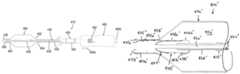
- FIG. 1is a side view of a first exemplary embodiment of an apparatus including a balloon for treating a body lumen, the apparatus operable in a first mode for infusing fluid into the body lumen and a second mode for inflating the balloon and/or otherwise performing a procedure within the body lumen.
- FIG. 2Ais a side view of the apparatus of FIG. 1 in the first mode for infusing fluid into a body lumen.
- FIG. 3is a perspective view of a distal end of another exemplary embodiment of an apparatus for treating a body lumen.
- FIG. 4Cis a cross-sectional view of the apparatus of FIGS. 3, 4A, and 4B taken along line 4 C- 4 C of FIG. 4B .
- FIG. 5is a cross-sectional view of an alternative embodiment of the apparatus of FIGS. 3 and 4A-4C .
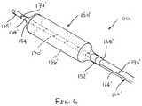
- FIG. 6is a perspective view of a distal end of yet another exemplary embodiment of an apparatus for treating a body lumen.
- FIGS. 7A and 7Bare side views of still another exemplary embodiment of an apparatus operable in a first mode for infusing fluid into a body lumen ( FIG. 7A ) and a second mode for delivering a prosthesis and/or performing a procedure within the body lumen ( FIG. 7B ).
- FIG. 7Cis a side view of the apparatus of FIGS. 7A and 7B , showing a constraint being advanced to deploy a prosthesis carried by the apparatus.
- FIGS. 8A and 8Bare side views of yet another exemplary embodiment of an apparatus operable in a first mode for infusing fluid into a body lumen proximal to a distal portion of the apparatus ( FIG. 8A ) and a second mode for delivering fluid into the body lumen distal to the distal portion ( FIG. 8B ).
- FIG. 9is a side view of another embodiment of an apparatus including a balloon for treating a body lumen and a valve for selectively delivering fluid from the apparatus.
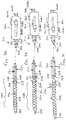
- FIGS. 12A and 12Bare side views of a distal end of another alternative embodiment of the apparatus of FIG. 9 , including a tensioning element for biasing the ends of the balloon away from one another, and showing the valve in open and closed positions, respectively.
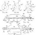
- FIGS. 14A-14Care cross-sectional views of alternative configurations of inner and outer members that may be provided on any of the apparatus herein.
- FIGS. 15A and 15Bare side views of distal ends of alternative embodiments of apparatus including a balloon and a valve member positionable at an intermediate condition in which fluid may be infused into a body lumen simultaneously with delivering fluid into the interior of the balloon.
- FIG. 17is a side view of a distal end of yet another exemplary embodiment of an apparatus for treating a body lumen.
- FIGS. 18A-18Care side views of distal ends of alternative embodiments of the apparatus of FIG. 17 .
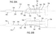
- FIGS. 20A and 20Bare side and top views, respectively, of another exemplary embodiment of an apparatus including an integrated inflation device.
- FIGS. 21A and 21Bare side views of still another exemplary embodiment of an apparatus for treating a body lumen including a rotatable curved distal tip, showing the distal tip in first and second orientations.
- FIG. 21Cis a side view of the apparatus of FIGS. 21A and 21B , showing a guidewire introduced through the apparatus to substantially straighten the distal tip.
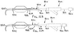
- FIGS. 22A and 22Bare side views of the apparatus of FIGS. 21A-21C , showing a valve thereof in closed and open positions, respectively.
- the outer member 20may be formed from one or more materials such as metal, plastic, e.g., PEEK, Grilamed L25, and the like, or composite materials.
- the outer member 20may have a length between about thirty and one hundred thirty centimeters (30-130 cm) and an outer diameter between about 1.2 and 2.0 millimeters, and the first lumen 26 may have a diameter between about 1.0 and 1.8 millimeters.
- the guidewire lumen 36 ′′may communicate between a distal port 36 a ′′ in the distal tip 35 ′′ and a proximal side port 36 b ′′ adjacent to the distal end 54 ′′ of the balloon 50 ′′.
- a guidewire(not shown) may be backloaded into the distal port 36 a ′′ through the guidewire lumen 36 ′′ and out the proximal port 36 b ′′, e.g., to provide a “rapid-exchange” lumen such that the guidewire need not be loaded through the entire length of the inner member 30 ′′.
- the second lumen 36shown in FIGS. 1-2B
- the inner member 30may have a substantially uniform construction along its length, or alternatively, the construction may be varied, similar to the outer member 20 .
- the inner member 30may be formed from a composite construction including a braided, helical, or other support structure, e.g., formed from metal, such as stainless steel, polymeric strong fiber, and the like, embedded in a polymeric matrix, e.g., a thermoset polymeric matrix, such as polyimide, that may resist the inner member 30 taking a shape set when bent or curved.
- the inner member 30may include a tether wire 31 coupled between the proximal and distal ends 32 , 34 , e.g., bonded or otherwise attached to the valve member 38 and/or balloon 50 , as shown in FIGS. 2A and 2B .
- the tether wire 31may be embedded in the shaft of the inner member 30 or may be free and/or external to the shaft other than at the valve member 38 and/or balloon 50 , as shown.
- the tether wire 31may be a high strength, relatively small cross-section wire or filament that may provide a safety feature to prevent the balloon 50 from becoming loose from the apparatus 10 , e.g., if the inner member 30 were somehow broken between the proximal and distal ends 32 , 34 during use.
- the inner member 30is sized to be slidably received within the first lumen 26 of the outer member 20 , e.g., such that an annular space is defined between the outer and inner members 20 , 30 for passing one or more fluids therethrough, as described further below.
- the inner member 30may have a length relative to the outer member 20 such that the inner member proximal end is received within or extends proximally beyond the outer member proximal end 22 , e.g., into the handle 60 , and the inner member distal end 34 extends distally beyond the outlet 27 of the outer member 20 , e.g., to define the distal portion 48 , as described further below.
- the distal tip 35may have a rounded, tapered, and/or other shape, e.g., to provide a substantially atraumatic tip for the apparatus 10 , similar to embodiments in the applications incorporated by reference herein.
- the handle 60may be coupled to or otherwise provided on the proximal end 22 of the outer member 20 , e.g., attached by one or more of an interference fit, bonding with adhesive, sonic welding, cooperating connectors (not shown), and the like.
- An actuator 60may be coupled to the proximal end of the inner member 30 for directing the inner member 30 axially relative to the outer member 20 , e.g., to open or close the outlet 27 and/or to direct the apparatus 10 between the different modes, as described further elsewhere herein.
- the handle 60may also include one or more ports 64 , e.g., a first port 64 a communicating with the first lumen 26 , and a second port 64 b communicating with the second lumen 36 , similar to embodiments in the applications incorporated by reference herein.
- ports 64e.g., a first port 64 a communicating with the first lumen 26 , and a second port 64 b communicating with the second lumen 36 , similar to embodiments in the applications incorporated by reference herein.
- the balloon 50includes proximal and distal ends 52 , 54 coupled to the distal portion 48 of the inner member 30 , e.g., a distal end 54 attached to the inner member 30 , e.g., adjacent the distal tip 35 , a proximal end 52 attached to the distal end 34 of the inner member 30 proximal to the distal tip 35 , thereby defining a substantially fluid-tight interior 56 .
- the distal end 54 of the balloon 50may be attached or otherwise secured directly to the distal end 24 of the outer member 20 and/or to the distal tip 35 to provide a fluid-tight connection, e.g., by one or more of bonding with adhesive, interference fit, sonic welding, fusing, engagement with a surrounding sleeve or other connector (not shown), and the like.
- the balloon 50may be formed from elastic material, e.g., to provide a compliant or semi-compliant balloon that may be expanded to a variety of sizes and/or shapes, e.g., based on the amount of fluid and/or pressure within the interior 56 .
- the balloon 50may be formed from substantially inelastic material, e.g., to provide a non-compliant balloon that expands to a predetermined size when inflated substantially independent of pressure (once a minimum volume and/or pressure is introduced to achieve the predetermined size).
- Such a non-compliant balloon 50may expand to the predetermined size even if inflated to relatively high pressures, e.g., until the balloon 50 bursts or otherwise ruptures, e.g., at pressures of at least ten atmospheres, twenty atmospheres, thirty atmospheres, and the like.
- the sealing or valve member 38is provided on or adjacent the distal portion 48 of the inner member 32 , e.g., adjacent the proximal end 52 of the balloon 50 .
- the sealing member 38may be attached to an outer surface of the inner member 30 and the proximal end 52 of the balloon 50 may be attached to the sealing member 38 .
- the proximal end 52 of the balloon 50extends at least partially over the sealing member 38 and may be attached to the sealing member 38 , e.g., by bonding with adhesive, sonic welding, fusing, interference fit, an exterior collar (not shown), and the like.
- the proximal end 52 of the balloon 50may have a substantially fluid-tight seal with the sealing member 38 and consequently the inner member 30 .
- the sealing member 38generally has a size to at least partially enter the first lumen 26 of the outer member 20 , e.g., such that the sealing member 38 may substantially seal the outlet 27 when the sealing member 38 is engaged with or received in the outlet 27 and/or first lumen 26 .
- the sealing member 38may include a valve body 38 a and one or more annular valve seals 38 b extending around the valve body 38 a .
- a single valve seal 38 bis shown, it will be appreciated that a plurality of valve seals (not shown) may be provided that are spaced apart axially from one another along a length of the valve body 38 a , e.g., to enhance the resulting seal.
- the valve body 38 amay have an outer diameter slightly smaller than the inner diameter of the first lumen 26 and/or outlet 27 , e.g., such that the valve body 38 a may freely enter the first lumen 26 through the outlet 27 .
- the valve seal(s) 38 bmay have an outer diameter that is slightly larger than the inner diameter of the first lumen 26 such that the valve seal(s) 38 b slidably engage the inner surface of the outer member 20 when the valve body 38 a enters the first lumen 26 .
- valve seal(s) 38 bmay be formed from resiliently flexible material, such as silicone or other elastomer, a low Durometer (e.g., 40 D) PEBAX material, polyurethane, and the like, that may be sufficiently compressible to accommodate sliding into the first lumen 26 without creating substantial friction, yet may resist deformation under substantial fluid pressure, e.g., to maintain a substantially fluid-tight seal against the inner wall of the outer member 20 .
- resiliently flexible materialsuch as silicone or other elastomer, a low Durometer (e.g., 40 D) PEBAX material, polyurethane, and the like, that may be sufficiently compressible to accommodate sliding into the first lumen 26 without creating substantial friction, yet may resist deformation under substantial fluid pressure, e.g., to maintain a substantially fluid-tight seal against the inner wall of the outer member 20 .
- valve seal(s) 38 bmay be formed from relatively harder, lubricious material that has mechanical compressibility, e.g., polyethylene tubular or other hollow structure that may bend in response to applied loads.
- the valve body 38 amay be formed from a different material than the valve seal(s) 38 b , e.g., to provide a more rigid base or support for the valve seal(s) 38 a , or may be formed from the same material, e.g., integrally molded, or otherwise formed from a single piece of material.
- the valve seal(s) 38 bmay slidably engage the inner surface of the outer member 20 to provide a substantially fluid-tight seal without requiring excessive force that may otherwise jam or damage the apparatus 10 during use.
- the sealing member 38may have a tapered shape to facilitate aligning and/or receiving the sealing member 38 within the outlet 27 .
- the valve body 38 amay include a tapered proximal end 38 c to guide the sealing member 38 into the outlet 27 and first lumen 26 , e.g., in case the outer and inner members 20 , 30 become out of concentric alignment with one another during use.
- a sealing member 38 ′may be provided that has an outer diameter that is larger than the inner diameter of the outlet 27 ′.
- the sealing member 38 ′may also include a tapered proximal end 38 c ′, e.g., to facilitate the sealing member 38 ′ engaging or being received at least partially within the outlet 27 ′ of the outer member 20 ′.
- the tapered proximal end 38 c ′may be received within the outlet 27 ′ until the larger midsection of the sealing member 38 ′ abuts the distal end 24 ′ of the outer member 20 ′ to provide a substantially fluid-tight seal.
- the sealing member 38may include one or more passages 39 extending generally longitudinally between the proximal end 38 c and a distal end 38 d of the sealing member 38 , e.g., a plurality of enclosed passages or grooves formed in the valve body 38 a .
- the valve body 38 amay be formed as an extrusion including a bore for receiving the inner member 30 and one or more enclosed passages 39 extending between the ends 38 c , 38 d .
- enclosed lumensmay be formed within the wall of the tubing to provide the passage(s) 39 using other methods.
- the sealing member 38 ′may be provided as a length of tubing with one or more longitudinal grooves formed in an inner surface thereof.
- the groove(s)may extend along the outer wall of the inner member 30 ′, thereby together defining the passage(s) 39 ′.
- the apparatus 10may include one or more markers to facilitate positioning and/or advancement of the apparatus 10 during use.
- radiopaque markers 29may be provided on the distal portion 48 of the inner member 30 , e.g., aligned with or adjacent the proximal and distal ends 52 , 54 of the balloon 50 .
- one or more radiopaque markersmay be provided on the outer member distal end 24 , on the distal tip 35 , on the balloon 50 , e.g., on the proximal and/or distal ends 52 , 54 , and/or on the sealing member(s) 38 .
- one or more components of the apparatus 10may be formed from radiopaque or other materials that may facilitate imaging the apparatus 10 during use.
- radiopaque markers and/or materialsmay facilitate positioning or otherwise imaging the apparatus 10 using fluoroscopy or other x-ray imaging, e.g., when positioning the balloon 50 (either before or after expansion) and/or when infusing fluid via the outlet 27 .
- echogenic markers and/or materialsmay be provided to facilitate imaging using ultrasound or similar imaging techniques.
- the sealing member 38may be placed around the inner member 30 at the desired location on the distal end 34 , e.g., proximal to the desired length for the distal portion 48 and attached thereto, e.g., by bonding with adhesive, sonic welding, fusing, heat shrinking, and the like.
- the proximal end 52 of the balloon 50may then be positioned partially over the sealing member 38 and attached thereto.
- the passage(s) 39may communicate from the outside of the proximal end 38 c of the sealing member 38 with the interior 56 of the balloon 50 .
- the distal tip 35may be attached to the inner member 30 , e.g., by an interference fit, bonding with adhesive, cooperating connectors, sonic welding, fusing, and the like.
- the distal end 54 of the balloon 50may be attached to the distal end 34 of the inner member 30 , e.g., closer to or over the distal tip 35 . Consequently, the interior 56 of the balloon 50 may be substantially sealed other than the passage(s) 39 through the sealing member 38 .
- the outer member 20may be positioned around the inner member 30 and the handle 60 and actuator 62 may be coupled to the outer and inner members 20 , 30 , respectively, e.g., similar to embodiments disclosed in the applications incorporated by reference herein.
- the apparatus 10may be operable in a first mode for delivering fluid into a body lumen (not shown) into which the apparatus 1010 is introduced (or otherwise exterior to the distal end 24 of the outer member 20 ) and a second mode for inflating the balloon 50 .
- the inner member 30may be movable between a first or distal position, shown in FIG. 2A , where the sealing member 38 is spaced apart from the outlet 27 of the outer member 20 , and a second or proximal position, shown in FIG. 2B , where the sealing member 38 at least partially enters the outlet 27 and first lumen 26 .
- first positionfluid delivered through the lumen 26 of the outer member 20 may exit the outlet 27 and enter the body lumen or other exterior environment, e.g., proximal to the distal portion 48 .
- valve seal(s) 38 bmay substantially seal the outlet 27 such that fluid delivered through the lumen 26 may enter through the passage(s) 39 in the sealing member 38 and into the interior 56 of the balloon 50 , thereby inflating the balloon 50 .
- a vacuummay be applied to the first lumen 26 to aspirate inflation media from the interior 56 , e.g., to collapse the balloon 50 when desired.
- FIG. 5an alternative embodiment of the apparatus 110 is shown similar to the apparatus 10 , 10 ′ described above.
- the apparatus 110includes an outer member 120 , an inner member 130 , a balloon 150 , and a sealing member 138 similar to the apparatus 10 , 10 ′.
- the apparatus 110may be operable in first and second modes by directing the inner member 130 between a first or distal position and a second or proximal position, also similar to the apparatus 10 , 10 ′.
- the apparatus 110includes a spring or other biasing mechanism 190 coupled between the inner and outer members 130 , 120 for biasing the inner member 130 to one of the first and second positions.
- the spring 190may bias the inner member 130 towards the proximal position, i.e., such that the outlet 127 of the apparatus 110 is normally closed and/or to enhance sealing the outlet 127 with the sealing member 138 .
- the biasmay be overcome by directing the inner member 130 distally to unseat the sealing member 138 and open the outlet 127 .
- the spring 190includes a first end 192 attached or otherwise coupled to the distal end 124 of the outer member 120 , and a second end 194 attached or otherwise coupled to the distal end 134 of the inner member 130 and/or the sealing member 138 .
- the second end 194 of the spring 190may be attached between the sealing member 138 and the inner member 130 or otherwise to the sealing member 138 , while still accommodating the passage 139 extending through the sealing member 138 .
- the ends 192 , 194 of the spring 190may be attached to the inner and outer members 130 , 120 by bonding with adhesive, sonic welding, fusing, interference fit, one or more connectors (not shown), and the like.
- the relative diameter of the spring 190 and the inner member 130may be set to reduce the risk of over-extension of the spring 190 .
- the spring 190may be relaxed or under slight tension when the inner member 130 is in the proximal position and may be placed under higher tension when the inner member 130 is directed distally. As the spring 190 is placed under higher tension, the diameter of the spring 190 may decrease thereby increasing friction between the spring 190 and the inner member 130 . This increasing friction may reduce the risk of over-extending the spring 190 , which may otherwise plastically deform the spring 190 or otherwise prevent the spring 190 from subsequently biasing the inner member 130 proximally towards the proximal position.
- FIG. 6yet another alternative embodiment of the apparatus 110 ′ is shown similar to the apparatus 110 of FIG. 5 .
- the apparatus 110 ′includes an outer member 120 ′, an inner member 130 ′, a balloon 150 ′, a sealing member 138 ′, and a spring 190 ′, similar to the apparatus 110 .
- the apparatus 110 ′may be operable in first and second modes by directing the inner member 130 ′ between a first or distal position and a second or proximal position, also similar to the apparatus 10 , 10 ′.
- the apparatus 110 ′includes a helical member 170 ′ within the balloon 150 ′ that may be expanded to an expanded helical shape, similar to embodiments in the applications incorporated by reference herein.
- the helical member 170 ′may include a first or proximal end coupled to the outer member 120 ′ (not shown) and a second or distal end 174 ′ coupled to the inner member 130 ′, adjacent the distal end 154 ′ of the balloon 150 ′.
- the apparatus 110 ′may also be operated in a third mode, e.g., by directing the inner member 130 ′ proximally from the second position to a third position in which the helical member 170 ′ is axially compressed and radially expanded.
- the balloon 150 ′may remain collapsed while the helical member 170 ′ is expanded or may be inflated and then collapsed after the helical member 170 ′ is expanded, similar to embodiments in the applications incorporated by reference herein.
- the inner member 130 ′may be directed distally to return the helical member 170 ′ to its original contracted shape around the inner member 130 ′. This action may extend the spring 190 ′ and open the outlet 127 ′.
- the relative sizes of the spring 190 ′ and the inner member 130 ′may be such that the spring 190 ′ compresses as it extends and frictionally engages the inner member 130 ′, thereby reducing the risk of the spring 190 ′ over-extending while the inner member 130 ′ is directed distally.
- FIGS. 21A-22Banother embodiment of an apparatus 810 is shown, which may be similar to the apparatus 10 , 10 ′ described above (or one or more of features of the apparatus 810 may be incorporated into any of the embodiments described herein or in the applications incorporated by reference herein).
- the apparatus 810generally includes an outer member 820 including proximal and distal ends 822 , 824 , an inner member 830 including proximal and distal ends 832 , 834 , a balloon 850 including proximal and distal ends 852 , 854 , and a sealing member 838 similar to the apparatus 10 , 10 ′.
- the apparatus 810also includes a flexible distal tip 835 extending from the distal end 834 of the inner member 830 that has a “J” tip or other curved shape.
- the distal tip 835may have a tapered shape that narrows distally from the balloon 850 or may have a substantially uniform cross-section (not shown), if desired.
- the distal tip 835may be biased to the curved shape yet may be resiliently flexible such that the distal tip 835 may be at least partially straightened, e.g., by directing a guidewire or other rail 99 having greater rigidity than the distal tip 835 through the distal tip 835 , as shown in FIG. 21C .
- the distal tip 835may resiliently adopt its curved shape, as shown in FIGS. 21A and 21B , e.g., to facilitate advancement of the apparatus 810 through a patient's body.
- the distal tip 835may be straightened, e.g., by introducing the guidewire 99 therethrough, to accommodate advancing the apparatus 810 over the guidewire 99 , as shown in FIG. 21C .
- the apparatus 810may be operable in first and second modes by directing the inner member 830 between a first or distal position where the valve is open (see FIG. 22A ), and a second or proximal position (see FIG. 22B ) where the valve is closed, similar to other embodiments herein.
- a handle 860may be provided on the proximal end 822 of the outer member, and an actuator 862 may be coupled to the proximal end 832 of the inner member 830 , similar to other embodiments herein.
- the actuator 862may be movable axially, i.e., proximally and distally relative to the handle 860 for directing the inner member 830 between the proximal and distal positions.
- the actuator 862 and inner member 830may be rotatable about a longitudinal axis of the apparatus 810 .
- the actuator 862may be rotated relative to the handle 860 to rotate the inner member 830 and thereby change the orientation of the curved distal tip 835 .
- FIGS. 21A and 21Bshow the curved distal tip 835 in opposite orientations, which may be achieved by rotating the actuator 862 about one hundred eighty degrees (180°) relative to the handle 860 .
- the inner member 830need be rotated.
- the outer member 820may become twisted or otherwise fail to transmit substantial torque between its proximal and distal ends 822 , 824 , e.g., if the outer member 820 is formed from polymeric material having poor torque transmission.
- the inner member 830may be decoupled from the outer member 820 , i.e., freely rotatable therein, thereby facilitating transmitting torque freely between the proximal and distal ends 832 , 834 .
- the shaft of the inner member 830may be formed from a composite or other construction that resists twisting.
- the inner member 830may be formed from a stainless steel (or other metal or polymeric strong fiber) braid in a polymeric matrix (e.g., a thermoset polymeric matrix, such as polyimide, that resists the inner member 830 taking a shape set when bent or curved).
- a polymeric matrixe.g., a thermoset polymeric matrix, such as polyimide, that resists the inner member 830 taking a shape set when bent or curved.
- Such constructionmay provide good flexibility while also maintaining substantial torque transmission between the proximal and distal ends 832 , 834 .
- the actuator 862may be freely rotatable relative to the handle 860 , if desired.
- cooperating featuresmay be provided, e.g., on the handle 860 and inner member 830 , to limit rotation of the actuator 862 and inner member 830 .
- one or more detents or tracksmay be provided within the handle 860 and/or on the proximal end 832 of the inner member 830 that interact to limit rotation to less than three hundred sixty degrees (360°).
- a usermay be able to rotate the actuator 862 to change the orientation of the curved distal tip 835 close to a complete rotation, while limiting excessive rotation in one direction, which may otherwise apply excessive torque on the inner member 830 .
- the actuator 862may be directed to the first position, thereby opening the valve and decoupling the distal end 824 of the outer member 820 from the sealing member 838 and, consequently, from the inner member 830 .
- the inner member 830may be rotated relative to outer member 820 to change the orientation of the distal tip 835 .
- the sealing member 838 and/or outer member 820may be constructed to minimize friction therebetween, e.g., to allow rotation of the inner member 830 in the second position with the valve closed.
- materials having a relatively low coefficient of frictione.g., PTFE, polyethylene, and the like, may be provided, e.g., on the outer surface of the sealing member 838 and/or on the inner surface of the distal end 824 of the outer member 820 .
- the membersmay freely rotate relative to one another even with the valve closed.
- the apparatus 10may be introduced into a body lumen (not shown), e.g., via a patient's vasculature or other natural or surgically created passages, to perform one or more therapeutic and/or diagnostic medical procedures.
- the target body lumenmay be a blood vessel, e.g., a vein or artery, a graft, e.g., an aorto-venous fistula, tubular xenograft, or synthetic tubular graft, and the like.
- the body lumenmay be a passage communicating between an adjacent artery and vein (not shown), e.g., in an arm or other region of a dialysis patient.
- the body lumenmay be a blood vessel within a patient's vasculature, e.g., a peripheral vessel in a patient's leg, a cerebral vessel, and the like.
- the materialmay be a stone within a patient's urinary tract or other foreign object to be removed from the patient's body.
- the body lumenmay be an aorta or a chamber of a heart, e.g., the site of a heart valve in need of repair, replacement, or other treatment.
- the body lumenmay be accessed using one or more additional instruments (not shown), which may be part of a system or kit including the apparatus 10 .
- additional instrumentsmay be part of a system or kit including the apparatus 10 .
- an introducer sheath, guide catheter, or other tubular membermay be introduced adjacent the target treatment site where material is to be removed, or may be introduced elsewhere in the patient's body to provide access to the patient's vasculature or other passages communicating with the body lumen.
- a percutaneous puncture or cut-downmay be created using a needle or other instrument (not shown) at a peripheral location, such as a femoral artery, carotid artery, or other entry site (also not shown), and an introducer sheath may be placed through the puncture at the peripheral location to provide access.
- the apparatus 10may be advanced through the patient's vasculature from the entry site, e.g., alone or with the aid of a guide catheter, guidewire, and the like (not shown).
- a guide catheter, micro-catheter, or other tubular bodymay be placed from the entry site to the body lumen using conventional methods.
- a guidewire(not shown) may be placed from the entry site to the body lumen if desired, e.g., if the inner member 30 includes the second lumen 36 .
- the guidewiremay be backloaded through the distal tip to facilitate advancing the apparatus 10 along the guidewire.
- the guide catheter or tubular bodymay also be used for aspiration, e.g., coupled to a source of vacuum for capturing material removed by the apparatus 10 , as described further below and in the applications incorporated by reference herein.
- the apparatus 10may be provided with the inner member 30 in the second position and the sealing member 38 substantially sealing the outlet 27 .
- the sealing member 38may also provide a substantially smooth transition for the distal end 24 of the outer member 20 (in addition to sealing the outlet 27 ), e.g., which may facilitate advancement of the apparatus 10 with minimal risk of damaging the walls of body lumens, e.g., when the apparatus 10 is advanced through tortuous anatomy.
- the apparatus 10may be introduced with the inner member 30 in the first position, i.e., with the outlet 27 open, if desired, to facilitate delivery of fluids during manipulation of the apparatus 10 .
- the distal tipmay be straightened during advancement over a guidewire or other rail. If desired to deploy the distal tip in its curved shape, the guidewire may be withdrawn partially until removed from the distal tip, whereupon the distal tip may resiliently return to its curved shape. The curved tip may then be rotated, e.g., by rotating the inner member if the inner member is rotatable independent of the outer member or the entire apparatus 10 , to access a branch or otherwise facilitate advancement of the apparatus 10 from one body lumen into another.
- the guidewiremay be advanced again to straighten the distal tip and advance the guidewire before advancing the apparatus 10 further.
- the inner member 30may be directed to (if not already in) the distal or first position to space the sealing member 38 from the distal end 24 of the outer member 20 and open the outlet 27 ( FIG. 2A ). Fluid may then be delivered through the lumen 26 of the outer member and out the outlet 27 into the body lumen. Because the outlet 27 is spaced away from the sealing member 38 , substantially all of the fluid is injected into the body lumen and does not pass through the passage(s) 39 into the balloon 50 .
- radiopaque contrast or other fluidmay be delivered into the body lumen via the annular passage defined by the first lumen 26 between the outer and inner members 20 , 30 to facilitate monitoring and/or identifying the location of the distal portion 48 and/or a target treatment site.
- Markers 29 (and/or other markers, not shown) on the apparatus 10may facilitate positioning the balloon 50 relative to the treatment site.
- contrastmay facilitate identifying obstructive material intended to be dilated or removed within a body lumen, an implantation site for a prosthesis, and the like before the balloon 50 is expanded, e.g., to facilitate verifying that the balloon 50 is positioned within or adjacent the treatment site.
- the inner member 30may be directed to (or may be automatically biased to) the proximal or second position, e.g., to substantially seal the outlet 27 with the sealing member 38 ( FIG. 2B ).
- the sealing member 38may provide a substantially fluid-tight seal of the outlet 27 such that subsequent fluid delivery through the first lumen 26 causes the fluid to pass through the passage(s) 39 of the sealing member 38 into the interior 56 of the balloon 50 , thereby inflating the balloon 50 .
- the apparatus 10may be positioned until the distal portion 48 and balloon 50 are positioned distally beyond an obstructed region within a body lumen.
- the balloon 50may be inflated within the body lumen, e.g., such that the balloon 50 extends substantially entirely across the body lumen.
- the entire apparatus 10may then be retracted to pull the material from the body lumen, e.g., to be aspirated into a guide catheter (not shown), or otherwise removed from the body lumen.
- the balloon 50may be directable to a helical configuration, similar to the apparatus in the applications incorporated by reference herein, e.g., to facilitate removal of material within the body lumen.
- the inner member 30may be directed back towards the second position, and fluid may be introduced through the outlet 27 to observe the amount of material removed and/or remaining within the body lumen. If additional material is to be removed, the inner member 30 may be directed to the first position, e.g., if desired to advance the apparatus 10 through additional material to be removed. Once the balloon 50 is located beyond the material, the process may be repeated as often as desired with the valve opened and closed to monitor the position of the balloon 50 and/or progress of removal.
- the inner member 30may be positioned at an intermediate position, i.e., between the first and second positions, e.g., as shown in FIG. 15B , in which fluid delivered from the outlet 27 may be divided such that some fluid enters the passage(s) 39 and expands the balloon 50 while the remaining fluid is delivered into the body lumen, as described further below.
- the relative amount of inflation and fluid delivery into the body lumenmay be adjusted, as desired, simply by directing the inner member 30 proximally or distally to move the sealing member 38 closer to or further from the outlet 27 . This procedure may be accomplished using external imaging, e.g., if the fluid includes radiopaque contrast, to monitor the inflation and/or position of the balloon 50 and/or the surrounding vasculature within which the balloon 50 is located.
- the apparatus 10may be used to deliver and aspirate fluid using the outlet 27 .
- a usermay want to deliver and remove one or more diagnostic and/or therapeutic agents within a body lumen using the apparatus 10 .
- contrast, dyes, or other material for facilitating imagingmay be delivered into the body lumen from the outlet 27 (with the inner member 30 and sealing member 38 in the first position) and then aspirated back into the outlet 27 to reduce the amount of contrast that remains within the body lumen or travels to other locations in the patient's body.
- the outer member 20may include one or more additional lumens (not shown, see, e.g., FIG. 14B ) extending between the proximal and distal ends 22 , 24 , if desired, e.g., for delivering and/or aspirating material into/from an exterior environment adjacent the distal end 24 .
- a lytic agentmay be delivered into the body lumen, e.g., to break up clot or other material within the body lumen, and then loose material may then be aspirated into the outlet 27 and through the lumen 26 (or into a guide catheter, not shown, positioned over the apparatus 10 ), which may reduce the risk of bleeding or otherwise exposing the lytic agent systemically to the patient's body.
- the outlet 27may also be used to aspirate pieces of thrombus or other material that is not dissolved or broken down by the agent and/or is otherwise loosened within the body lumen.
- the balloon 50may be at least partially inflated, e.g., by directing the inner member 30 to an intermediate position, as shown in FIG. 15B , to stop or reduce flow through the body lumen while the one or more agents are delivered and aspirated, which may also reduce exposure of other locations to the agent(s) delivered into the body lumen.
- the first lumen 26may be used for both inflation of the balloon 50 and delivering fluid into the body lumen.
- the profile of the outer member 20 and therefore of the overall apparatus 10may be smaller than devices that include separate inflation and infusion lumens.
- the second lumen 36 of the inner member 30could be used for infusion of fluids, this would generally require removing the guidewire over which the apparatus 10 is introduced since the guidewire may substantially fill the second lumen 36 .
- the guidewiremay remain within the second lumen 36 throughout the procedure, thereby potentially reducing the number of guidewire or other device exchanges.
- the apparatus 10may remain over the guidewire, which may facilitate advancing the apparatus 10 to other target body lumens intended for treatment, as explained in the applications incorporated by reference herein.
- the body lumen 90may include an occlusion 94 , e.g., a partial or chronic total occlusion within a blood vessel, and the apparatus 10 may be introduced to dilate and/or otherwise treat the occlusion 94 .
- a guidewire 99has been tracked from an entry site (not shown) into the body lumen 90 and through the occlusion 94 , e.g., using known methods.
- Chronic total lesionsmay be particularly difficult to treat because there is little opportunity to perform conventional dye injections to facilitate imaging since there is no flow through the body lumen 90 . Further, it may be difficult to track and/or position the guidewire 99 and/or apparatus 10 within the body lumen 90 without using dye injections.
- the apparatus 10may be advanced into the body lumen 90 with the balloon 50 in its collapsed condition.
- the apparatus 10may be advanced over the guidewire 99 previously placed through the occlusion 94 , e.g., until the distal end 54 of the balloon 50 enters the region of the body lumen 90 beyond the occlusion 94 , as shown.
- the apparatus 10may facilitate positioning the balloon 50 relative to the occlusion 94 before the balloon 50 is expanded, e.g., to facilitate verifying that the balloon 50 is positioned through and/or across the occlusion 94 .
- the inner member 30may be directed back and forth between the first and second positions, e.g., to allow infusion of contrast and inflation of the balloon 50 to dilate the occlusion 94 and monitor the progress of the treatment.
- the apparatus 10may facilitate dye injection adjacent the occlusion 94 while maintaining the guidewire 99 in position.
- conventional devicesmay require removing a guidewire or other device advanced through the occlusion 94 to allow dye injections and imaging around the occlusion 94 . In such procedures, it may be difficult to reintroduce the guidewire or other device back through the small passage created through the occlusion 94 .
- obstructive materialmay be treated, e.g., at least partially dissolved, macerated, and the like before, during, or after withdrawal.
- a therapeutic agentmay be delivered into the body lumen 90 via the first lumen 26 and outlet 27 of the outer member 20 , e.g., to at least partially dissolve or separate thrombus or other relatively soft material before being dilated by the balloon 50 .
- the distal portion 48may carry one or more other treatment elements, e.g., an abrasive tip, a passive or active atherectomy tool, and the like (not shown), in addition to or instead of the balloon 50 . Exemplary tips and methods for using them are disclosed in application Ser. No. 12/966,925, filed Dec. 13, 2010, the entire disclosure of which is expressly incorporated by reference herein.
- a stent 96may be carried by the balloon 50 and may be expanded by inflating the balloon 50 .
- dye 95may be injected into the body lumen 90 to facilitate imaging and positioning the apparatus 10 .
- the valvemay be closed, and the balloon 50 may be inflated to expand the stent 96 and dilate the occlusion 94 (not shown).
- the balloon 50may be collapsed and the apparatus 10 removed from the body lumen 90 and patient's body.
- the apparatus 10may be used to introduce and/or deploy other prostheses instead of or in addition to the stent 96 .
- a tubular stent-graft, one or more components of a prosthetic valve, and the likemay be carried by the distal portion 48 , e.g., over the balloon 50 .
- the prosthesismay be expanded or otherwise deployed within a body lumen, e.g., by inflating the balloon 50 , as described above, with fluid being selectively introduced, as desired.
- the apparatus 10 ′′may be used as a drug delivery platform for treating the occlusion 94 .
- the apparatus 10 ′′includes a carrier 98 ′′ provided over the balloon 50 ′′ that may be delivered into the body lumen 90 and/or through the occlusion 94 ′′.
- the apparatus 10 ′′may be advanced into the body lumen 90 with the balloon 50 ′′ and the carrier 98 ′′ thereon in a collapsed condition, e.g., over the guidewire 99 .
- contrast, dye, or other fluid 95may be delivered from the outlet 27 ′′ into the body lumen 90 to facilitate locating and/or measuring the size of the occlusion 94 and/or body lumen 90 , e.g., using fluoroscopy.
- the valvemay be closed and the balloon 50 ′′ inflated within the body lumen 90 to dilate the occlusion 94 and deliver the carrier 98 ′′.
- the carrier 98 ′′is delivered, the balloon 50 ′′ may be collapsed and the apparatus 10 ′′ removed from the body lumen 90 and patient's body.
- One or more therapeutic agentsmay be positioned within or otherwise carried by the carrier 98 ′′ and, therefore, may remain within the dilated occlusion 94 to treat the body lumen 90 .
- the agent(s)may be delivered directly from the wall of the balloon 50 ′′.
- the agent(s)may be infused through the wall of the balloon 50 ′′, e.g., by providing a porous layer on the balloon 50 ′′ into which the agent(s) may be embedded or otherwise placed.
- the agent delivered into the body lumen 90may be provided from multiple components that may react or interact in situ once delivered together within the body lumen 90 .
- a first component(or one or more additional components less than all components of the agent) may be carried on the wall of the balloon 50 ′′, e.g., in a porous layer or on a carrier 98 ′′ disposed around the balloon 50 ′′, as described above.
- a balloonmay be provided on the distal end 24 of the outer member 20 or on the distal portion 48 of the inner member 30 distal to the balloon 50 , if desired, similar to embodiments in the applications incorporated by reference herein.
- a balloonmay be a non-compliant, high pressure balloon, e.g., for dilating the body lumen, or an elastic, compliant balloon for substantially sealing the body lumen to isolate one or more regions of the body lumen before infusion of fluid therein.
- the outer and/or inner members 20 , 30may include one or more additional lumens, e.g., as shown in FIGS. 14A-14C , providing inflation lumens for such additional balloons.
- FIGS. 7A-7Canother embodiment of an apparatus 210 is shown that includes a tubular outer member 220 , an elongate inner member 230 , and a distal portion 248 carrying a treatment element, e.g., a stent or other prosthesis 296 covered by a cover or other constraint 298 .
- the apparatus 210may be operable in multiple modes, e.g., first and second modes, by directing the inner member 230 between a first or distal position and a second or proximal position for opening and closing a valve adjacent the distal portion 248 , similar to other embodiments herein.
- the apparatus 210may be operable for deploying the prosthesis carried on the distal portion 248 , as described further below.
- the outer member 220includes a proximal end 222 coupled to a handle 260 , a distal end 224 sized for introduction into a body lumen, and a first lumen 226 extending between the proximal end 222 and an outlet 227 in the distal end 224 .
- the inner member 230also includes a proximal end 232 , a distal end 234 , and, optionally, may include a second lumen 236 extending between the proximal end 232 and a distal tip 235 .
- the inner member 230may include an actuator member (not shown), e.g., slidably disposed within an actuator lumen (also not shown), coupled with the constraint 298 for selectively actuating the constraint 298 , e.g., advancing the constraint distally or otherwise to deploy the prosthesis 296 , as described further below.
- an actuator membere.g., slidably disposed within an actuator lumen (also not shown)
- the constraint 298for selectively actuating the constraint 298 , e.g., advancing the constraint distally or otherwise to deploy the prosthesis 296 , as described further below.
- the inner member 230may have a length relative to the outer member 220 such that the inner member proximal end 230 is coupled to an actuator 264 on the handle 260 , and the inner member distal end 234 extends distally beyond the outlet 227 of the outer member 220 , e.g., to define the distal portion 248 .
- the actuator 260may be coupled to the proximal end 232 of the inner member 230 for directing the inner member 230 axially relative to the outer member 220 , e.g., to open or close the outlet 227 and/or to direct the apparatus 210 between the different modes, similar to other embodiments herein.
- the distal portion 248includes the prosthesis 296 and constraint 298 adjacent a tapered proximal portion 238 , extending at least partially between the proximal portion 238 and the distal tip 235 .
- the tapered portion 238may taper outwardly and distally from the inner member 230 to define an outer diameter similar to or larger than the outlet 227 of the outer member 220 , e.g., to provide a sealing member for selectively sealing the outlet 227 , similar to other embodiments herein.
- the tapered portion 238may be formed from material similar to the rest of the distal portion 248 , or the tapered portion 238 may be formed from flexible and/or resilient material to enhance the seal with the outlet 227 .
- the inner member 230may be movable between a first or distal position, shown in FIG. 7B , where the outlet 227 is spaced apart from the proximal portion 238 , and a second or proximal position, shown in FIG. 7A , where the tapered portion 238 engages the outlet 227 to substantially seal the outlet 227 .
- the actuator 262may be directed between distal and proximal positions on the handle 260 to open and close the outlet 227 , as shown, e.g., to allow fluid to be delivered from the first lumen 226 through the outlet 227 into a body lumen or other region adjacent the distal portion 248 .
- the distal portion 248may have an outer diameter similar to the maximum diameter of the tapered portion 238 , e.g., a substantially uniform diameter between the tapered portion 238 and the distal tip 235 .
- the distal portion 248may step down from the tapered portion 238 , e.g., to accommodate receiving the prosthesis 296 thereon.
- the constraint 298may be movable from a first position overlying the stent 296 and a second position for exposing the stent 296 .
- an actuator 266 on the handle 260may be advanced distally to direct an actuator member (not shown) in the inner member 330 and consequently the constraint 298 distally to expose the stent 296 .
- the stent 296may be self-expanding, i.e., biased to expand to a diameter larger than a body lumen within which the stent 296 is intended to be deployed.
- the stent 296may resiliently expand as it is exposed until the constraint 298 is advanced sufficiently to expose the entire stent 296 .
- other constraintsmay be provided instead of the sleeve 298 shown, e.g., one or filaments or elements (not shown) that may surround the stent 296 and/or secure the stent 296 on the distal portion 248 in a constrained state, yet may be withdrawn to release the stent 296 from the constrained state and allow the stent 296 to resiliently expand to a deployed state.
- a balloon or other expandable membermay be provided on the distal portion 248 , e.g., underlying the stent 296 .
- the balloonmay be inflated, e.g., by delivering fluid through the first lumen 266 with the inner member 230 in the second position such that the fluid passes through the outlet 227 and one or more passages (not shown) in the tapered portion 238 into an interior of the balloon.
- the balloonmay be inflated to plastically or otherwise further expand the stent 296 after deployment and/or dilate the body lumen within which the stent 296 is deployed.
- the stent 296may be plastically expandable, e.g., similar to the embodiments described elsewhere herein.
- the constraint 298may still be provided, if it is desired to protect the stent 296 (or other prosthesis) and/or provide a transition over the distal portion 248 .
- the constraint 298may be omitted and the stent 296 may be maintained on the distal portion 248 , e.g., by compressing the stent 296 or by the stent 296 having a substantially relaxed state corresponding to the constrained state.
- a balloon or other expandable membermay be provided on the distal portion 248 to expand the stent 296 , similar to other embodiments herein.
- FIGS. 8A and 8Banother embodiment of an apparatus 310 is shown that includes a tubular outer member 320 , an elongate inner member 330 , and a distal portion 348 , which may carry a treatment element, e.g., a balloon, stent or other prosthesis, and the like (not shown).
- the outer member 320includes a proximal end coupled to a handle (not shown), a distal end 324 sized for introduction into a body lumen, and a first lumen 326 extending between the proximal end and an outlet 827 in the distal end 324 .
- the inner member 330also includes a proximal end (not shown), a distal end 334 , and, optionally, may include a second lumen 336 extending between the proximal end and a distal tip 335 .
- the inner member 330may be coupled to an actuator (not shown) on the handle, e.g., for directing the inner member 330 between a first or distal position, shown in FIG. 8A , and a second or proximal position, shown in FIG. 8B , for opening and closing a valve adjacent the distal portion 348 .
- the distal portion 348may extend from a tapered proximal portion 338 to the distal tip 335 .
- the tapered portion 338may taper outwardly and distally from the inner member 330 to define an outer diameter similar to or larger than the outlet 327 of the outer member 320 , e.g., to provide a sealing member for selectively sealing the outlet 327 , similar to other embodiments herein.
- the tapered portion 338may be formed from material similar to the rest of the distal portion 348 , or the tapered portion 338 may be formed from flexible and/or resilient material to enhance the seal with the outlet 327 .
- a separate sealing membermay be formed on or attached to the distal end 334 of the inner member 330 , e.g., similar to the sealing members 38 , 38 ′ described previously.
- the distal portion 348may have a diameter similar to other portions of the inner member 330 .
- the distal portion 348may include one or more passages 339 extending at least partially along a length thereof, e.g., from one or more proximal ports 339 a in the tapered portion 338 to one or more respective distal ports 339 b in the distal portion, e.g., adjacent the distal tip 335 .
- the distal portion 348may include a balloon or other expandable member (not shown), a stent or other prosthesis, and/or other treatment elements, similar to previous embodiments.
- a balloonmay be attached to the distal end 334 of the inner member 330 such that an interior of the balloon communicates with an inflation lumen (not shown) in the inner member 330 , which may be the lumen 336 or a separate lumen, e.g., similar to the configuration shown in FIG. 14C .
- the inner member 330may be movable between a first or distal position, shown in FIG. 8A , where the outlet 327 is spaced apart from the proximal portion 338 , and a second or proximal position, shown in FIG. 8B , where the tapered portion 338 engages the outlet 327 to substantially seal the outlet 327 .
- the actuatormay be directed between distal and proximal positions on the handle to open and close the outlet 327 . With the outlet 327 open and the inner member 330 in the first position, as shown in FIG.
- fluid delivered through the first lumen 326may exit the outlet 327 into a body lumen or other region adjacent, e.g., proximal to, the distal portion 348 , as represented by arrows 95 .
- fluid delivered through the first lumen 326may enter the proximal port(s) 339 a of the passage(s) 339 and exit the distal port(s) 339 b , e.g., distally beyond the distal portion 348 , as represented by arrows 95 .
- the inner member 348may be actuated to selectively deliver fluid on either side of the distal portion 348 .
- the apparatus 310may be introduced into a body lumen to perform one or more medical procedures, similar to the other embodiments herein.
- the distal portion 348may be positioned at a target treatment site, and a treatment element (not shown) on the distal portion 348 may be used to treat the target site.
- fluidmay be delivered proximal or distal to the treatment element, e.g., to monitor use of the treatment element, similar to other embodiments herein.
- FIGS. 9-10Banother embodiment of an apparatus 410 is shown for treating a body lumen that includes an outer tubular member 420 , an inner member 430 , and an expandable balloon 450 carried by the inner and/or outer members 420 , 430 .
- the apparatus 410may be operable in multiple modes, for example, a first mode for delivering fluid into a body lumen ( FIG. 10B ), and a second mode for expanding the balloon 450 ( FIG. 10B ), e.g., to remove material, dilate, or otherwise treat a body lumen, deliver a prosthesis, and the like, similar to other embodiments herein.
- the outer member 420includes a proximal end 422 , a distal end 424 sized for introduction into a body lumen, and a first lumen 426 extending therebetween.
- the inner member 430also includes a proximal end (not shown), a distal end 434 , and, optionally, may include a second lumen 436 extending between the proximal and distal ends 434 , which may be sized to slidably receive a guide wire or other instrument (not shown) therethrough.
- the balloon 450includes a proximal end 452 coupled to the outer member distal end 424 , a distal end 454 including an outlet 458 , and an interior 456 communicating with the first lumen 426 and the outlet 458 .
- the distal end 454 of the balloon 450may be integrally formed with the main wall of the balloon 450 (defining the interior 456 ), and, optionally, the proximal end 452 of the balloon 450 .
- the balloon 450may be formed from elastic material, e.g., to provide a compliant or semi-compliant balloon, or from substantially inelastic material, e.g., to provide a non-compliant balloon, similar to other embodiments herein and in the applications incorporated by reference herein.
- a distal tip 435may be integrally formed with, attached to, or otherwise provided on the distal end 454 of the balloon 450 , e.g., surrounding or otherwise defining the outlet 458 and/or reinforcing the distal end 454 .
- the distal tip 435may include a tapered outer shape, e.g., to provide a substantially atraumatic tip for the balloon 450 .
- the distal tip 435includes a stepped-down inner surface, e.g., defining a relatively small diameter distal region 435 a and a relatively large diameter proximal region 435 b .
- a valve seal liner 437may be provided within the outlet 458 , e.g., in the recess defined by the stepped-down regions 435 a , 435 b , to further support the outlet 458 and/or distal tip 435 , if desired.
- the valve seal liner 437may be a separate sleeve attached to the distal tip 435 , e.g., by an interference fit, bonding with adhesive, sonic welding, fusing, and the like.
- the liner sleevemay be formed from a tube or other material having greater radial and/or longitudinal rigidity than the distal tip 454 of the balloon 450 .
- valve seal liner 437may be integrally formed with the distal tip 435 and/or distal end 454 of the balloon 450 , e.g., with properties of the material modified to enhance support of the distal end 454 and/or outlet 458 .
- a sealing or valve member 438may be carried on the inner member distal end 434 , e.g., such that the sealing member 438 is movable relative to the balloon 450 as the inner member 430 is moved, e.g., for selectively opening and closing the outlet 458 to provide a valve.
- the sealing member 438is disposed within the interior 456 of the balloon 450 such that the sealing member 438 may be spaced apart from the outlet 458 in the proximal or first position to open the outlet 458 , and may be seated within the distal end 454 and/or distal tip 435 in the distal or second position to seal the outlet 458 .
- the sealing member 438may include a substantially atraumatic tip, e.g., a rounded, softened, beveled, or “J” or other curved tip, (not shown), that may extend beyond the distal tip 435 , similar to embodiments in the applications incorporated by reference herein.
- a substantially atraumatic tipe.g., a rounded, softened, beveled, or “J” or other curved tip, (not shown), that may extend beyond the distal tip 435 , similar to embodiments in the applications incorporated by reference herein.
- valve sealse.g., annular valve seal 438 b may be integrally formed on or attached to the valve body 438 a , similar to previous embodiments, e.g., to enhance a seal between the sealing member 438 and the distal end 454 of the balloon 450 and/or the distal tip 435 .
- a stop 478may be provided on the sealing member 438 for limiting distal movement of the inner member 430 relative to the distal end 454 of the balloon 450 . As best seen in FIGS. 10A and 10B , the stop 478 may be a band attached around the sealing member 438 proximal to the valve seal 438 b.
- the inner member 430may be directed proximally, e.g., until the sealing member 438 is withdrawn entirely into the interior 456 of the balloon 450 , thereby opening the outlet 458 .
- fluid delivered into the first lumen 426passes through the interior 456 and distal end 454 of the balloon 450 and through the distal tip 435 and outlet 458 into the body lumen beyond the apparatus 410 .
- the inner member 430may be withdrawn to partially withdraw the sealing member 438 from the outlet 458 , e.g., as shown in FIG. 15A , to provide some resistance to flow through the outlet 458 such that the balloon 450 is partially inflated while fluid is delivered from the outlet 458 .
- the inner member 430may be directed distally to direct the sealing member 438 into and/or through the distal end 454 of the balloon 450 and/or the distal tip 435 to substantially seal the outlet 458 .
- the sealing member 438 and/or distal end 454e.g., the valve seal liner 437 and the valve seal 438 b
- fluid delivered into the first lumen 426 of the outer member 420may remain within the balloon interior 456 to expand the balloon 450 .
- the stop 478 and valve seal liner 437may have substantially flat and/or blunt end surfaces that contact one another, e.g., to prevent further advancement of the inner member 430 .
- the stop 478 and valve seal liner 437may provide sufficient support to reduce the risk of the distal end 454 of the balloon 450 migrating distally as may otherwise occur as pressurized fluid is delivered into the interior 456 to expand the balloon 450 .
- the inner member 430may be advanced to press the stop 478 against the distal end 454 and/or distal tip 435 and push the distal end 454 of the balloon 450 away from the proximal end (not shown), thereby slightly stretching the balloon 450 and/or enhancing the seal.
- This configurationmay also minimize or otherwise reduce the profile of the balloon 450 , e.g., to facilitate introduction into a patient's body.
- distal advancement of the inner member 430may be limited, e.g., by an actuator on the proximal end (not shown) of the apparatus 410 .
- the valve seal liner 437 , distal end 454 , distal tip 435 , and/or the sealing member 438may include a lubricious coating or material, such as PTFE, if desired to reduce friction between the components, similar to embodiments in the applications incorporated by reference herein.
- the sealing member 438may be received substantially within the distal end 454 of the balloon 450 and/or the distal tip 435 .
- the sealing member 438may be disposed substantially entirely beyond the expandable portion of the balloon 450 , i.e., outside the interior 456 . This configuration may facilitate folding, compressing, or otherwise minimizing a profile of the balloon 450 in its collapsed condition, which may facilitate introduction of the apparatus 410 into a body lumen.
- the tensionmay prevent the distal end 454 ′ of the balloon 450 ′ from following the sealing member 438 ′ and buckling or otherwise compressing the balloon 450 ′ axially rather than opening the outlet 458 ′.
- FIGS. 12A and 12Banother embodiment of an apparatus 410 ′′ is shown for treating a body lumen that includes an outer tubular member (not shown), an inner member 430 ′′ with a sealing member 438 ′′, and an expandable balloon 450 ′′ carried by the outer member and inner member 430 ′′, generally similar to previous embodiments.
- the apparatus 410 ′′may be operable in multiple modes, e.g., a first mode for infusing fluid into a body lumen via outlet 458 ′′ ( FIG. 12A ), and a second mode where the outlet 458 ′′ is sealed by the sealing member 438 ′′ for expanding the balloon 450 ′′ ( FIG. 12B ).
- the balloon 450 ′′includes a proximal end (not shown) coupled to the outer member distal end, a distal end 454 ′′ defining the outlet 458 ′′, and an interior 456 ′′ communicating with the first lumen and the outlet 458 ′′.
- the balloon 450 ′′may be formed from elastic material, e.g., to provide a compliant or semi-compliant balloon, or from substantially inelastic material, e.g., to provide a non-compliant balloon, similar to other embodiments herein.
- a distal tip 435 ′′may be integrally formed with, attached to, or otherwise provided on the distal end 454 ′′ of the balloon 450 , e.g., surrounding or otherwise defining the outlet 458 ′′ and/or reinforcing the distal end 454 ′′.
- the distal tip 435 ′′may include a tapered outer shape, e.g., to provide a substantially atraumatic tip for the balloon 450 ′′ when the sealing member 328 ′′ is fully seated in the outlet 458 ′′.
- the distal tip 435 ′′includes a stepped-down inner surface, e.g., defining a relatively small diameter distal region 435 a ′′ and a relatively large diameter proximal region 435 b ′′.
- a valve seal liner(not shown) may be provided within the outlet 458 ′′, e.g., in the recess defined by the stepped-down regions 435 a ′′, 435 b ′′, similar to the previous embodiment.
- valve seal 438 b ′′may be sufficiently flexible such that the valve seal 438 b ′′ is compressed slightly inwardly when received within the distal end 454 ′′ and/or outlet 458 ′′, e.g., within the proximal region 435 b ′′ of the distal tip 435 ′′, to provide a substantially fluid-tight seal without creating substantial friction between the valve seal 438 b ′′ and the distal end 454 ′′.
- a sealing member 438 ′′′may be provided that includes a valve seal 438 b ′′′ that has a relaxed outer diameter that is slightly smaller than the proximal region 435 b ′′′ of the distal end 454 ′′′.
- valve seal 438 b ′′′ and sealing member 438 ′′′may be freely seated and/or withdrawn from the outlet 458 ′′′ and/or distal end 454 ′′′ with minimal or no interference and/or friction, as shown in FIG. 13A .
- valve seal 438 b ′′′may be formed from relatively soft, flexible material such that, as shown in FIG. 13B , when the inner member 430 ′′′ is pushed distally with sufficient force, the valve seal 438 b ′′ may compress axially and consequently expand radially, thereby engaging the proximal region 435 b ′′′ of the distal tip 435 ′′′. This interference fit may then provide a substantially fluid-tight seal of the outlet 458 ′′′.
- the pressurization within the interior 456 ′′′may apply a distal force on the sealing member 438 ′′′ to further compress the sealing member 438 ′′′ and expand the valve seal 438 b ′′′.
- the valve seal 438 b ′′′may resiliently contract radially, thereby disengaging the proximal region 435 b ′′′ and reducing any interference or friction that may otherwise resist withdrawal of the sealing member 438 ′′′ from the outlet 458 ′′.
- a tensioning element 457 ′′may be provided for applying tension on the balloon 450 ′′ (or other embodiments herein), e.g., to push the distal end 454 ′′ distally.
- the tensioning element 457 ′′may be a compression spring with a first end 457 a ′′ coupled to the stop 478 ′′ on the sealing member 438 ′′ and a second end 457 a ′′ coupled to the distal end 454 ′′, e.g., the recess between the stepped-down regions 435 a ′′, 435 b ′′.
- the inner member 430 ′′may be directed to a distal or second position, where the sealing member 438 ′′ is advanced into and/or through the distal tip 435 ′′ and/or distal end 454 ′′ of the balloon 450 ′′ to substantially seal the outlet 458 ′′.
- the tensioning element 457 ′′may be compressed, thereby biasing the distal tip 435 ′′ and/or distal end 454 ′′ to move distally away from the sealing member 438 ′′.
- fluid delivered into the first lumen 426 ′′ of the outer member 420 ′′may remain within the balloon interior 456 ′′ to expand the balloon 450 ′′, similar to previous embodiments.
- the tensioning member 457 ′′may ensure that the distal end 454 ′′ and distal tip 435 ′′ do not move proximally with the sealing member 438 ′′.
- the force of the tensioning element 457 ′′may prevent the distal end 454 ′′ of the balloon 450 ′′ from following the sealing member 438 ′′ and potentially buckling or compressing the balloon 450 ′′ rather than opening the outlet 458 ′′.
- the sealing member 438may be directed to an intermediate position such that the outlet 458 is not fully sealed.
- the balloon 450may be partially inflated, while fluid also exits the outlet 458 .
- the relative amount of expansion and fluid deliverymay be manually adjusted, if desired, e.g., based upon the anatomy and/or intended procedure.
- the handlemay include an indicator (not shown) to identify one or more intermediate positions.
- the usermay be able to identify an intermediate position based on resistance to fluid being injected, e.g., with increased resistance indicating that the balloon 450 is being inflated.
- the sealing member 438may be advanced to seal the outlet 458 and maintain the balloon 450 in the partially or fully expanded condition for a desired amount of time. After sufficient time has passed, vacuum may be applied to the first lumen 426 to evacuate fluid from the balloon 450 to collapse the balloon 450 and restore normal flow. Alternatively, the sealing member 438 may be withdrawn to open the outlet 458 and allow the balloon 450 to deflate and/or vacuum may be applied to evacuate fluid from the body lumen as well as the balloon 450 .
- one or more therapeutic agentssuch as thrombus lysing agents or vasodilators, may be delivered into a body lumen via the outlet 458 .
- Causing the balloon 450 to at least partially expandmay allow greater residence time of the agent(s) in a target treatment site.
- there may be improved effectiveness of the agent(s) and/or smaller volumesmay be delivered since natural flow through the body lumen may be temporarily slowed or stopped by the balloon 450 .
- FIG. 17still another embodiment of an apparatus 510 is shown for treating a body lumen similar to other embodiments herein.
- the apparatus 510includes an outer tubular member 520 , an inner member 530 , an expandable balloon 550 , and a handle 560 , which may be constructed similar to previous embodiments and the embodiments in the applications incorporated by reference herein.
- the outer member 520includes a proximal end (not shown), a distal end 524 sized for introduction into a body lumen, and a first lumen 526 extending along a central longitudinal axis 527 therebetween.
- the inner member 530also includes a proximal end (not shown), a distal end 534 , and, optionally, a second lumen 536 , e.g., sized to slidably receive a guidewire or other instrument (not shown) therethrough.
- the balloon 550includes proximal and distal ends 552 , 554 that are both attached or otherwise coupled to the outer member 520 .
- the outer member 520includes one or more openings 529 in the distal end 524 such that an interior 556 communicates with the first lumen 526 via the opening(s) 529 .
- the distal end 534 of the inner member 530may extend through the distal end 524 of the outer member 520 , e.g., beyond an outlet 558 in the outer member 520 such that the outlet 558 defines an annular passage between the outer and inner members 520 , 530 .
- the distal end of the balloonmay be attached to the inner member or the distal end of the balloon may include an outlet end that surrounds the inner member, e.g., similar to embodiments disclosed elsewhere herein and in the applications incorporated by reference herein.
- the handle 560may be attached to or otherwise provided on the proximal end of the outer member 520 , e.g., for manipulating the outer member 520 and/or the entire apparatus 510 . Similar to previous embodiments and embodiments in the applications incorporated by reference herein, the handle 560 may include an actuator (not shown) for operating the apparatus 510 in multiple modes, e.g., a first mode for dilating an obstruction within a body lumen, and a second mode for infusing fluid into a body lumen.
- the actuatormay be movable to direct the inner member 530 relative to the outer member 520 between a first or proximal position where the nosecone 538 may be partially received in or otherwise engage the distal end 524 of the outer member 520 to substantially seal the outlet 558 and a second or distal position where the nosecone 538 is spaced away from the outer member 520 to open the outlet 558 , similar to previous embodiments.
- the inner member 530may be integrally incorporated into the apparatus 510 , similar to previous embodiments.
- the inner member 530may be decoupled or independent from the other components of the apparatus 510 .
- the inner member 530may be introduceable into a patient's body independently from the outer member 520 , e.g., over a guidewire or instead of a guidewire. Once the distal end 534 is positioned at a desired location within the patient's body, the rest of the apparatus 510 , i.e., the outer member 520 with the balloon 550 collapsed may be advanced over the inner member 530 to the desired location.
- the proximal end of the inner member 530 extending from the patient's bodymay be backloaded through the outlet 558 , and the outer member 520 advanced until the proximal end of the inner member 530 is received in or extends from the handle 560 .
- the relative length of the outer and inner members 520 , 530may be such that the outlet 558 is disposed adjacent the nosecone 538 when the proximal end of the inner member 530 is received in or extends from the handle 560 .
- the handle 560may include a coupler (not shown) that may be activated to engage the inner member 530 to a push button, thumb control, or other actuator (not shown) on the handle 560 once the outer member 520 is advanced sufficiently over the inner member 530 .
- the actuatormay be activated to direct the inner member 530 and nosecone 538 axially relative to the outer member 520 to seal or open the outlet 558 .
- other embodiments described elsewhere hereinmay be decoupled in this manner, i.e., provided with the inner member independent from the outer member and/or other components of the apparatus.
- an independent inner member 530may include one or more markers or other visual indicators (not shown) that may provide confirmation to a user that the outer member 520 has been advanced sufficiently to place the outlet 558 adjacent the nosecone 538 .
- a markermay be provided on the proximal end of the inner member 530 that may be visible when the proximal end of the inner member 530 extends from the handle 560 , thereby providing a visual indication that the nosecone 538 is sealing or adjacent the outlet 558 .
- the outer member 520may be advanced until the distal end 524 contacts or engages the nosecone 538 , which may provide tactile feedback that the nosecone 538 may be used to seal or open the outlet 558 .
- the outlet 558may be opened and fluid delivered into the desired location, e.g., contrast to facilitate imaging the desired location, or one or more diagnostic and/or therapeutic agents.
- the nosecone 538may be directed proximally to seal the outlet 558 , and fluid delivered to inflate the balloon 550 , e.g., to dilate a stenosis or other lesion at the desired location, similar to methods described elsewhere herein.
- the apparatus 510may be directed to another location or removed from the patient's body.
- the outer and inner members 520 , 530may be removed together or the outer member 520 may be removed first (e.g., after decoupling the outer member 520 from the inner member 530 if coupled together after advancing the outer member 520 over the inner member 530 ).
- one or more treatment elementsmay be provided in addition to or instead of the balloon 550 .
- an apparatus 510 amay be provided that is generally similar to apparatus 510 , except that a prosthesis 596 a is provided on the distal end 524 a .
- the prosthesis 596 amay be a stent that may be crimped or otherwise loaded over the balloon 550 a .
- the outlet 558 amay be sealed with the nosecone 538 a , and the balloon 550 a inflated to expand the stent 596 a within the target treatment site, e.g., to dilate and support an obstructed region within a blood vessel.
- other prosthesesmay be loaded on the apparatus 510 a , such as a stent-graft, a prosthetic valve, and the like, similar to other embodiments herein.
- FIG. 18Banother embodiment of an apparatus 510 b is shown that includes a plurality of treatment elements, namely a plurality of electrodes or other conductive elements 596 b on the balloon 550 b .
- the elements 596 bmay be attached to or embedded in the balloon wall 550 b in a desired pattern, e.g., a plurality of longitudinal elements spaced apart from one another about a circumference of the balloon 550 b , as shown.
- the elements 596 bmay be coupled to an energy source, e.g., a radiofrequency generator coupled to a handle (not shown) on the proximal end of the apparatus 510 b .
- a plurality of wires or other conductorsmay extend through the outer member 520 b from the elements 596 b to a connector on the handle (not shown) to which the generator may be connected.
- the balloon 550 bmay be inflated to expand the elements 596 b , e.g., to press them against the wall of the body lumen.
- the generatormay then be activated to deliver energy into the wall via the elements 596 b , to ablate, heat, or otherwise treat tissue surrounding the body lumen.
- the outlet 558 bmay be selectively opened and closed during the procedure, e.g., before or after delivering the energy, to facilitate imaging, or otherwise monitor or enhance treatment.
- an apparatus 510 cthat includes one or more cryogenic treatment elements 596 c carried by the balloon 550 c and/or the distal end 524 c of the apparatus 510 c .
- the cryogenic element(s)may include a cooling apparatus within the balloon 550 c powered by compressed gas having thermodynamic properties that cause cooling upon expansion of the gas within the interior of the balloon 550 c.
- the balloon 550 cmay be inflated, e.g., to press the balloon 550 c against the wall of the body lumen. Cooling gas may then be released within the interior of the balloon 550 c to cool surrounding tissues to freeze, modify, or otherwise treat tissue surrounding the body lumen, e.g., to reduce the risk of restenosis within a blood vessel. Similar to previous embodiments, the outlet 558 c may be selectively opened and closed during the procedure, e.g., before or after delivering the cooling gas, to facilitate imaging, or otherwise monitor or enhance treatment.
- FIGS. 19A and 19Banother embodiment of an apparatus 610 is shown that includes an outer tubular member 620 , an inner member 630 , and an expandable balloon 650 , which may be constructed similar to previous embodiments and the embodiments in the applications incorporated by reference herein.
- the outer member 620may include a proximal end (not shown), a distal end 624 sized for introduction into a body lumen, and a first lumen 626 extending therebetween.
- the inner member 630also includes a proximal end (not shown), a distal end 634 , and a second lumen 636 extending therebetween.
- the second lumen 636may be sized for receiving one or more instruments therethrough, e.g., one or more catheters, sheaths, or other devices (not shown), which may be substantially larger than a guidewire.
- the second lumen 636may have a diameter between about one and four millimeters (1-4 mm).
- the apparatus 610may provide a guide catheter or guide sheath that may be introduced into a body lumen and through which one or more other devices may be introduced to perform a procedure.
- a dilator(not shown) may be provided within the second lumen 636 , e.g., to support the apparatus 610 and/or to provide a transition or atraumatic tip for the apparatus 610 .
- the inner member 630may be slidably received within the first lumen 626 of the outer member 620 , e.g., such that an annular space is defined between the outer and inner members 620 , 630 for passing one or more fluids therethrough.
- One or more sealing memberse.g., a nosecone 638 , may be provided on the distal end 634 of the inner member 630 to provide a valve, also similar to previous embodiments.
- the balloon 650includes proximal and distal ends 652 , 654 that are both attached or otherwise coupled to the outer member 620 , and the outer member 620 may include one or more openings (not shown) in the distal end 624 such that an interior of the balloon 650 communicates with the first lumen 626 via the opening(s).
- the distal end 634 of the inner member 630may extend through the distal end 624 of the outer member 620 , e.g., beyond an outlet 658 in the outer member 620 such that the outlet 658 defines an annular passage between the outer and inner members 620 , 630 .
- the distal end 654 of the balloon 650may be attached to the inner member 630 or the distal end 654 of the balloon 650 may include an outlet end that surrounds the inner member, e.g., similar to embodiments disclosed elsewhere herein and in the applications incorporated by reference herein.
- any fluid introduced into the first lumen 626enters the interior of the balloon 650 , thereby expanding the balloon 650 .
- the balloon 650may remain collapsed and any fluid introduced through the first lumen 626 may exit the outlet 658 into a body lumen within which the apparatus 610 is introduced.
- the apparatus 610may provide a guide or access sheath that includes a valve adjacent the balloon 650 , which may be selectively opened and closed to deliver fluid when the second lumen 636 is used for other purposes.
- FIGS. 20A and 20Bstill another embodiment of an apparatus 710 is shown that includes a catheter or other elongate member 720 including proximal and distal ends 722 , 724 and a balloon 750 carried on the distal end 724 .
- the apparatus 710may include an inner member and/or valve (not shown), similar to previous embodiments and embodiments in the applications incorporated by reference herein.
- the apparatus 710includes a handle 750 coupled to or otherwise on the proximal end 722 that includes an integrated inflation device.
- Previous embodimentsgenerally include a handle with a port to which an external inflation device, such as a syringe and the like (not shown) may be coupled.
- the apparatus 710includes an inflation device incorporated directly into the handle 750 .
- the inflation deviceincludes a barrel or housing 752 and a piston 754 slidably received in the barrel 752 such that a fluid-tight seal is provided between the piston 754 and barrel 752 .
- the handle 750may include a fixed gripping surface 756 coupled to the barrel 752 and a movable gripping surface 758 coupled to the piston 754 .
- a pressure gauge 766may be attached to the barrel 752 to provide an indicator of the pressure of fluid within the barrel 752 .
- a filling port 768is attached to or extends from the barrel 752 , e.g., including a valve that may be selectively opened and closed, to allow fluids (e.g., liquids or gases) to be delivered into or removed from the barrel 752 .
- the valvemay be closed to provide a fixed volume of fluid for delivery into the balloon 750 .
- the valvemay include a control, e.g., a button, lever, stopcock, and the like (not shown), that may be manually opened and closed by the user, or the valve may be automatically opened and closed, e.g., when a luer fitting or other connector (not shown) is connected to or disconnected from the filling port 768 , e.g., a luer-activated valve.
- the piston 754includes one or more helical threads 760 on its exterior surface that may be engaged with a split nut assembly or other actuator 764 .
- the assembly 764may include a button 762 that, when pushed or otherwise activated, disengages the split nut threads from the piston threads 760 .
- the distal end 724 of the catheter 720may introduced into a body lumen, e.g., similar to other embodiments herein.
- the piston 754may be advanced relative to the barrel 752 .
- the usermay hold the fixed gripping surface 756 with one hand and the movable gripping surface 758 with the other.
- the button 762 on the split nut assembly 764may be depressed to disengage the threads 760 , and the piston 754 may be advanced into the barrel 752 to inject fluid through the catheter 720 into the balloon 750 .
- the button 762may then be released, and the threads 760 may automatically reengage.
- the movable gripping surface 758may be rotated and the split nut assembly 762 may slide along the threads 760 , e.g., to advance the piston 754 further into the barrel 752 .
- a higher forceand resulting pressure may be applied to the balloon 750 than by manually advancing the piston 754 with the threads 760 disengaged.
Landscapes
- Health & Medical Sciences (AREA)
- Life Sciences & Earth Sciences (AREA)
- Heart & Thoracic Surgery (AREA)
- Engineering & Computer Science (AREA)
- Biomedical Technology (AREA)
- Public Health (AREA)
- Animal Behavior & Ethology (AREA)
- General Health & Medical Sciences (AREA)
- Veterinary Medicine (AREA)
- Surgery (AREA)
- Vascular Medicine (AREA)
- Anesthesiology (AREA)
- Hematology (AREA)
- Biophysics (AREA)
- Pulmonology (AREA)
- Molecular Biology (AREA)
- Medical Informatics (AREA)
- Nuclear Medicine, Radiotherapy & Molecular Imaging (AREA)
- Child & Adolescent Psychology (AREA)
- Orthopedic Medicine & Surgery (AREA)
- Cardiology (AREA)
- Oral & Maxillofacial Surgery (AREA)
- Transplantation (AREA)
- Physics & Mathematics (AREA)
- Pathology (AREA)
- Media Introduction/Drainage Providing Device (AREA)
- Surgical Instruments (AREA)
Abstract
Description
Claims (8)
Priority Applications (1)
| Application Number | Priority Date | Filing Date | Title |
|---|---|---|---|
| US15/698,622US10624656B2 (en) | 2008-07-03 | 2017-09-07 | Apparatus and methods for treating obstructions within body lumens |
Applications Claiming Priority (16)
| Application Number | Priority Date | Filing Date | Title |
|---|---|---|---|
| US7833008P | 2008-07-03 | 2008-07-03 | |
| US15362009P | 2009-02-18 | 2009-02-18 | |
| US21466709P | 2009-04-27 | 2009-04-27 | |
| US21573209P | 2009-05-08 | 2009-05-08 | |
| US12/497,135US8043313B2 (en) | 2008-07-03 | 2009-07-02 | Apparatus and methods for treating obstructions within body lumens |
| US27162709P | 2009-07-23 | 2009-07-23 | |
| US28303509P | 2009-11-25 | 2009-11-25 | |
| US34275510P | 2010-04-19 | 2010-04-19 | |
| US39785410P | 2010-06-17 | 2010-06-17 | |
| US12/843,004US8945160B2 (en) | 2008-07-03 | 2010-07-23 | Apparatus and methods for treating obstructions within body lumens |
| US40216610P | 2010-08-25 | 2010-08-25 | |
| US201161463537P | 2011-02-19 | 2011-02-19 | |
| US201161520927P | 2011-06-17 | 2011-06-17 | |
| US13/216,208US9101382B2 (en) | 2009-02-18 | 2011-08-23 | Apparatus and methods for treating obstructions within body lumens |
| US14/803,112US9757137B2 (en) | 2009-02-18 | 2015-07-20 | Apparatus and methods for treating obstructions within body lumens |
| US15/698,622US10624656B2 (en) | 2008-07-03 | 2017-09-07 | Apparatus and methods for treating obstructions within body lumens |
Related Parent Applications (1)
| Application Number | Title | Priority Date | Filing Date |
|---|---|---|---|
| US14/803,112ContinuationUS9757137B2 (en) | 2008-07-03 | 2015-07-20 | Apparatus and methods for treating obstructions within body lumens |
Publications (2)
| Publication Number | Publication Date |
|---|---|
| US20170367720A1 US20170367720A1 (en) | 2017-12-28 |
| US10624656B2true US10624656B2 (en) | 2020-04-21 |
Family
ID=46673214
Family Applications (4)
| Application Number | Title | Priority Date | Filing Date |
|---|---|---|---|
| US13/216,208ActiveUS9101382B2 (en) | 2008-07-03 | 2011-08-23 | Apparatus and methods for treating obstructions within body lumens |
| US13/444,739ActiveUS8926649B2 (en) | 2009-02-18 | 2012-04-11 | Apparatus and methods for treating obstructions within body lumens |
| US14/803,112ActiveUS9757137B2 (en) | 2008-07-03 | 2015-07-20 | Apparatus and methods for treating obstructions within body lumens |
| US15/698,622Active2029-10-15US10624656B2 (en) | 2008-07-03 | 2017-09-07 | Apparatus and methods for treating obstructions within body lumens |
Family Applications Before (3)
| Application Number | Title | Priority Date | Filing Date |
|---|---|---|---|
| US13/216,208ActiveUS9101382B2 (en) | 2008-07-03 | 2011-08-23 | Apparatus and methods for treating obstructions within body lumens |
| US13/444,739ActiveUS8926649B2 (en) | 2009-02-18 | 2012-04-11 | Apparatus and methods for treating obstructions within body lumens |
| US14/803,112ActiveUS9757137B2 (en) | 2008-07-03 | 2015-07-20 | Apparatus and methods for treating obstructions within body lumens |
Country Status (7)
| Country | Link |
|---|---|
| US (4) | US9101382B2 (en) |
| EP (1) | EP2675517B1 (en) |
| JP (1) | JP6158715B2 (en) |
| CN (1) | CN103476351B (en) |
| CA (1) | CA2827641C (en) |
| SG (1) | SG192850A1 (en) |
| WO (1) | WO2012112949A2 (en) |
Families Citing this family (79)
| Publication number | Priority date | Publication date | Assignee | Title |
|---|---|---|---|---|
| US20040226556A1 (en) | 2003-05-13 | 2004-11-18 | Deem Mark E. | Apparatus for treating asthma using neurotoxin |
| US7686825B2 (en) | 2004-03-25 | 2010-03-30 | Hauser David L | Vascular filter device |
| US8483831B1 (en) | 2008-02-15 | 2013-07-09 | Holaira, Inc. | System and method for bronchial dilation |
| JP2011519699A (en) | 2008-05-09 | 2011-07-14 | インノブアトイブエ プルモナルイ ソルウトイオンス,インコーポレイティッド | Systems, assemblies and methods for treatment of bronchial trees |
| US8939991B2 (en) | 2008-06-08 | 2015-01-27 | Hotspur Technologies, Inc. | Apparatus and methods for removing obstructive material from body lumens |
| US8945160B2 (en)* | 2008-07-03 | 2015-02-03 | Hotspur Technologies, Inc. | Apparatus and methods for treating obstructions within body lumens |
| US9101382B2 (en) | 2009-02-18 | 2015-08-11 | Hotspur Technologies, Inc. | Apparatus and methods for treating obstructions within body lumens |
| US20120109057A1 (en) | 2009-02-18 | 2012-05-03 | Hotspur Technologies, Inc. | Apparatus and methods for treating obstructions within body lumens |
| WO2011056684A2 (en) | 2009-10-27 | 2011-05-12 | Innovative Pulmonary Solutions, Inc. | Delivery devices with coolable energy emitting assemblies |
| WO2011060200A1 (en) | 2009-11-11 | 2011-05-19 | Innovative Pulmonary Solutions, Inc. | Systems, apparatuses, and methods for treating tissue and controlling stenosis |
| US8911439B2 (en) | 2009-11-11 | 2014-12-16 | Holaira, Inc. | Non-invasive and minimally invasive denervation methods and systems for performing the same |
| EP2462976A1 (en)* | 2010-12-08 | 2012-06-13 | Biotronik AG | High-pressure-tight slide bearing device for minimally-invasive instruments |
| US20130190813A1 (en)* | 2012-01-24 | 2013-07-25 | St. Jude Medical Puerto Rico Llc | Balloon location device manifold for vascular closure device and methods |
| KR20140133548A (en)* | 2012-03-09 | 2014-11-19 | 클리어스트림 테크놀러지스 리미티드 | Medical balloon with multi-position actuator for precisely arranging the working surface |
| US9332998B2 (en)* | 2012-08-13 | 2016-05-10 | Covidien Lp | Apparatus and methods for clot disruption and evacuation |
| US9332999B2 (en)* | 2012-08-13 | 2016-05-10 | Covidien Lp | Apparatus and methods for clot disruption and evacuation |
| WO2014047650A1 (en) | 2012-09-24 | 2014-03-27 | Inceptus Medical LLC | Device and method for treating vascular occlusion |
| US8784434B2 (en) | 2012-11-20 | 2014-07-22 | Inceptus Medical, Inc. | Methods and apparatus for treating embolism |
| US9398933B2 (en) | 2012-12-27 | 2016-07-26 | Holaira, Inc. | Methods for improving drug efficacy including a combination of drug administration and nerve modulation |
| EP2938387B1 (en)* | 2012-12-31 | 2021-12-08 | C.R. Bard Inc. | Balloon catheter with adjustable inner member |
| US9919137B2 (en) | 2013-08-28 | 2018-03-20 | Edwards Lifesciences Corporation | Integrated balloon catheter inflation system |
| US9895194B2 (en) | 2013-09-04 | 2018-02-20 | Boston Scientific Scimed, Inc. | Radio frequency (RF) balloon catheter having flushing and cooling capability |
| US9901716B2 (en)* | 2013-09-10 | 2018-02-27 | Cook Medical Technologies Llc | Tipless balloon catheter with stiffening member through balloon |
| EP3035876B1 (en) | 2013-09-18 | 2018-11-14 | Xablecath Inc. | Device and system for crossing and treating an occlusion |
| EP3057511B1 (en)* | 2013-10-14 | 2022-12-28 | Adagio Medical, Inc. | Endoesophageal balloon catheter and system |
| US10238406B2 (en) | 2013-10-21 | 2019-03-26 | Inari Medical, Inc. | Methods and apparatus for treating embolism |
| TWI633900B (en)* | 2014-03-31 | 2018-09-01 | 日商東麗股份有限公司 | Ablation catheter with balloon |
| CN106470728A (en) | 2014-06-09 | 2017-03-01 | 因赛普特斯医学有限责任公司 | Retraction and suction device and related systems and methods for treating embolism |
| US9545263B2 (en)* | 2014-06-19 | 2017-01-17 | Limflow Gmbh | Devices and methods for treating lower extremity vasculature |
| US9956381B2 (en)* | 2014-09-26 | 2018-05-01 | Florida Electrophysiology Llc | Concepts for catheter control and stabilization |
| JP6442229B2 (en)* | 2014-10-30 | 2018-12-19 | 株式会社グッドマン | Balloon catheter |
| JP7044552B2 (en) | 2015-01-20 | 2022-03-30 | キューアペル メディカル, エルエルシー | Tubular structure with variable support |
| DE102015009190A1 (en)* | 2015-07-16 | 2017-01-19 | B. Braun Avitum Ag | dialysis cannula |
| US9700332B2 (en) | 2015-10-23 | 2017-07-11 | Inari Medical, Inc. | Intravascular treatment of vascular occlusion and associated devices, systems, and methods |
| CN113796927B (en) | 2015-10-23 | 2025-03-04 | 伊纳里医疗公司 | Intravascular treatment of vascular occlusion and related devices, systems and methods |
| US10342571B2 (en) | 2015-10-23 | 2019-07-09 | Inari Medical, Inc. | Intravascular treatment of vascular occlusion and associated devices, systems, and methods |
| US10034681B2 (en)* | 2015-10-30 | 2018-07-31 | Acclarent, Inc. | Fluid communication features for Eustachian tube dilation instrument |
| CN115300748A (en) | 2015-12-18 | 2022-11-08 | 伊纳里医疗有限公司 | Catheter shaft and related devices, systems and methods |
| US20170189059A1 (en)* | 2016-01-06 | 2017-07-06 | Boston Scientific Scimed, Inc. | Percutaneous access device |
| CN110022925B (en) | 2016-07-27 | 2024-05-28 | 乔佩尔医疗公司 | Tubular structure with variable support |
| US11660121B2 (en) | 2016-10-18 | 2023-05-30 | East End Medical Llc | Transseptal insertion device |
| FI3528717T3 (en) | 2016-10-24 | 2024-08-09 | Inari Medical Inc | Devices for treating vascular occlusion |
| US10653523B2 (en) | 2017-01-19 | 2020-05-19 | 4C Medical Technologies, Inc. | Systems, methods and devices for delivery systems, methods and devices for implanting prosthetic heart valves |
| US10716667B2 (en) | 2017-01-20 | 2020-07-21 | Medtronic Vascular, Inc. | Transcatheter delivery systems and delivery catheters for prosthetic mitral valve delivery, and methods for prosthetic mitral valve delivery using a retrograde approach |
| US12029647B2 (en) | 2017-03-07 | 2024-07-09 | 4C Medical Technologies, Inc. | Systems, methods and devices for prosthetic heart valve with single valve leaflet |
| EP4018946A1 (en) | 2017-05-03 | 2022-06-29 | Medtronic Vascular, Inc. | Tissue-removing catheter |
| US11690645B2 (en) | 2017-05-03 | 2023-07-04 | Medtronic Vascular, Inc. | Tissue-removing catheter |
| US12036113B2 (en) | 2017-06-14 | 2024-07-16 | 4C Medical Technologies, Inc. | Delivery of heart chamber prosthetic valve implant |
| US10639152B2 (en)* | 2017-06-21 | 2020-05-05 | Edwards Lifesciences Corporation | Expandable sheath and methods of using the same |
| US10874839B2 (en)* | 2017-07-13 | 2020-12-29 | Acclarent, Inc. | Adjustable instrument for dilation of anatomical passageway |
| WO2019050765A1 (en) | 2017-09-06 | 2019-03-14 | Inari Medical, Inc. | Hemostasis valves and methods of use |
| CN108210114B (en)* | 2018-01-18 | 2024-02-13 | 刘建强 | Intrahepatic bile duct tectorial membrane stent and use method thereof |
| US11154314B2 (en) | 2018-01-26 | 2021-10-26 | Inari Medical, Inc. | Single insertion delivery system for treating embolism and associated systems and methods |
| US11491313B2 (en) | 2018-02-20 | 2022-11-08 | Crossliner, Inc. | Guide catheter extension system with a delivery micro-catheter configured to facilitate percutaneous coronary intervention |
| US11642500B2 (en) | 2018-02-20 | 2023-05-09 | Crossliner, Inc. | Intravascular delivery system and method for percutaneous coronary intervention |
| US20190255299A1 (en)* | 2018-02-20 | 2019-08-22 | Crossliner, Llc | Intravascular delivery system and method for percutaneous coronary intervention |
| CA3114285A1 (en) | 2018-08-13 | 2020-02-20 | Inari Medical, Inc. | System for treating embolism and associated devices and methods |
| WO2020051591A1 (en)* | 2018-09-07 | 2020-03-12 | Icahn School Of Medicine At Mount Sinai | Heart valve delivery system and method with rotational alignment |
| CN118697424A (en) | 2018-11-16 | 2024-09-27 | 美敦力瓦斯科尔勒公司 | Tissue Removal Catheter |
| US12420069B2 (en) | 2018-12-19 | 2025-09-23 | Covidien Lp | Internal carotid artery thrombectomy devices and methods |
| US20230190295A1 (en)* | 2019-03-08 | 2023-06-22 | William Chase | Bleeding control device |
| US11452628B2 (en) | 2019-04-15 | 2022-09-27 | 4C Medical Technologies, Inc. | Loading systems for collapsible prosthetic heart valve devices and methods thereof |
| US11819236B2 (en) | 2019-05-17 | 2023-11-21 | Medtronic Vascular, Inc. | Tissue-removing catheter |
| CA3141251A1 (en) | 2019-06-11 | 2020-12-17 | East End Medical, Llc | Directional balloon transseptal insertion device for medical procedures with improved transseptal puncture system with puncture member balloon seal |
| US20210077185A1 (en)* | 2019-09-13 | 2021-03-18 | Biosense Webster (Israel) Ltd. | Seals and reinforcement for irrigated electrophysiology balloon catheter with flexible-circuit electrodes |
| AU2020349508A1 (en) | 2019-09-20 | 2022-04-14 | East End Medical, Llc | Directional balloon transseptal insertion device for medical procedures with improved transseptal puncture system with puncture member balloon seal |
| AU2020357991A1 (en) | 2019-10-04 | 2022-04-21 | East End Medical, Llc | Directional balloon transseptal insertion device for medical procedures with improved handle |
| JP7638273B2 (en) | 2019-10-16 | 2025-03-03 | イナリ メディカル, インコーポレイテッド | Systems, devices and methods for treating vascular obstructions |
| CN114599297B (en)* | 2019-10-31 | 2025-02-11 | 日本瑞翁株式会社 | Balloon catheter for foreign body removal |
| CN113069165B (en)* | 2020-01-03 | 2025-05-27 | 捷锐士股份有限公司 | Valve loader method, system and apparatus |
| US12133797B2 (en)* | 2020-01-31 | 2024-11-05 | 4C Medical Technologies, Inc. | Prosthetic heart valve delivery system: paddle attachment feature |
| AU2021221979A1 (en) | 2020-02-18 | 2022-09-15 | East End Medical, Llc | Deflectable anchor balloon catheter for vascular procedures |
| US12053375B2 (en) | 2020-03-05 | 2024-08-06 | 4C Medical Technologies, Inc. | Prosthetic mitral valve with improved atrial and/or annular apposition and paravalvular leakage mitigation |
| US11992403B2 (en) | 2020-03-06 | 2024-05-28 | 4C Medical Technologies, Inc. | Devices, systems and methods for improving recapture of prosthetic heart valve device with stent frame having valve support with inwardly stent cells |
| US11712266B2 (en) | 2021-06-25 | 2023-08-01 | Vantis Vascular, Inc. | Enhanced guide extension system for the efficient delivery of leads |
| US20230200894A1 (en)* | 2021-12-23 | 2023-06-29 | Biosense Webster (Israel) Ltd. | Couplers, strain relief hubs, and nose pieces for an ablation catheter assembly and methods of using the same |
| EP4463083A1 (en) | 2022-01-11 | 2024-11-20 | Inari Medical, Inc. | Devices for removing clot material from intravascularly implanted devices, and associated systems and methods |
| WO2023147460A1 (en) | 2022-01-27 | 2023-08-03 | Contego Medical, Inc. | Thrombectomy and aspiration system and methods of use |
| CN116965909B (en)* | 2023-07-25 | 2024-04-30 | 苏州海宇新辰医疗科技有限公司 | Double-layer balloon catheter for cryoablation based on novel inflation mode |
Citations (198)
| Publication number | Priority date | Publication date | Assignee | Title |
|---|---|---|---|---|
| US396754A (en) | 1889-01-29 | Catheter | ||
| JPS4998183U (en) | 1972-12-15 | 1974-08-23 | ||
| US4029104A (en) | 1976-03-08 | 1977-06-14 | Kerber Charles W | Calibrated leak balloon micro-catheter |
| US4030503A (en) | 1975-11-05 | 1977-06-21 | Clark Iii William T | Embolectomy catheter |
| US4273128A (en) | 1980-01-14 | 1981-06-16 | Lary Banning G | Coronary cutting and dilating instrument |
| US4315512A (en) | 1980-01-24 | 1982-02-16 | Fogarty Thomas J | Piston extension balloon dilatation catheter apparatus and method |
| US4545367A (en) | 1982-07-16 | 1985-10-08 | Cordis Corporation | Detachable balloon catheter and method of use |
| US4646742A (en) | 1986-01-27 | 1987-03-03 | Angiomedics Incorporated | Angioplasty catheter assembly |
| US4649922A (en) | 1986-01-23 | 1987-03-17 | Wiktor Donimik M | Catheter arrangement having a variable diameter tip and spring prosthesis |
| US4653496A (en) | 1985-02-01 | 1987-03-31 | Bundy Mark A | Transluminal lysing system |
| JPS62233168A (en) | 1986-04-03 | 1987-10-13 | オリンパス光学工業株式会社 | Catheter |
| US4706671A (en) | 1985-05-02 | 1987-11-17 | Weinrib Harry P | Catheter with coiled tip |
| EP0275230A2 (en) | 1987-01-15 | 1988-07-20 | FOGARTY, Thomas J. | Catheter with corkscrew-like balloon |
| US4784636A (en) | 1987-04-30 | 1988-11-15 | Schneider-Shiley (U.S.A.) Inc. | Balloon atheroectomy catheter |
| WO1989001352A1 (en) | 1987-08-07 | 1989-02-23 | Target Therapeutics | Valved catheter device and method |
| US4813934A (en)* | 1987-08-07 | 1989-03-21 | Target Therapeutics | Valved catheter device and method |
| US4821722A (en) | 1987-01-06 | 1989-04-18 | Advanced Cardiovascular Systems, Inc. | Self-venting balloon dilatation catheter and method |
| US4848344A (en) | 1987-11-13 | 1989-07-18 | Cook, Inc. | Balloon guide |
| US4848342A (en) | 1985-09-13 | 1989-07-18 | Martin Kaltenbach | Dilation catheter |
| US4886062A (en) | 1987-10-19 | 1989-12-12 | Medtronic, Inc. | Intravascular radially expandable stent and method of implant |
| US4890611A (en) | 1988-04-05 | 1990-01-02 | Thomas J. Fogarty | Endarterectomy apparatus and method |
| US4894051A (en) | 1984-05-14 | 1990-01-16 | Surgical Systems & Instruments, Inc. | Atherectomy system with a biasing sleeve and method of using the same |
| US4921478A (en) | 1988-02-23 | 1990-05-01 | C. R. Bard, Inc. | Cerebral balloon angioplasty system |
| US4926858A (en) | 1984-05-30 | 1990-05-22 | Devices For Vascular Intervention, Inc. | Atherectomy device for severe occlusions |
| US4950277A (en) | 1989-01-23 | 1990-08-21 | Interventional Technologies, Inc. | Atherectomy cutting device with eccentric wire and method |
| WO1991003996A1 (en) | 1989-09-15 | 1991-04-04 | Interventional Thermodynamics, Inc. | Method and device for thermal ablation of hollow body organs |
| JPH0380872A (en) | 1989-05-12 | 1991-04-05 | Samuel Shiber | Atelectomy apparatus |
| US5011488A (en) | 1988-12-07 | 1991-04-30 | Robert Ginsburg | Thrombus extraction system |
| US5032113A (en) | 1989-04-13 | 1991-07-16 | Scimed Life Systems, Inc. | Innerless catheter |
| US5035705A (en) | 1989-01-13 | 1991-07-30 | Scimed Life Systems, Inc. | Method of purging a balloon catheter |
| US5059176A (en) | 1989-12-21 | 1991-10-22 | Winters R Edward | Vascular system steerable guidewire with inflatable balloon |
| US5085636A (en) | 1989-01-13 | 1992-02-04 | Scimed Life Systems, Inc. | Balloon catheter with inflation-deflation valve |
| US5090959A (en) | 1987-04-30 | 1992-02-25 | Advanced Cardiovascular Systems, Inc. | Imaging balloon dilatation catheter |
| US5100423A (en) | 1990-08-21 | 1992-03-31 | Medical Engineering & Development Institute, Inc. | Ablation catheter |
| US5102402A (en) | 1991-01-04 | 1992-04-07 | Medtronic, Inc. | Releasable coatings on balloon catheters |
| US5135494A (en) | 1988-08-01 | 1992-08-04 | Target Therapeutics | Valved catheter device and method |
| US5135531A (en) | 1984-05-14 | 1992-08-04 | Surgical Systems & Instruments, Inc. | Guided atherectomy system |
| US5141518A (en) | 1991-03-05 | 1992-08-25 | Progressive Angioplasty Systems, Inc. | Angioplasty catheter with close-fitting guidewire and tube |
| US5171221A (en) | 1991-02-05 | 1992-12-15 | Target Therapeutics | Single lumen low profile valved balloon catheter |
| US5176698A (en) | 1991-01-09 | 1993-01-05 | Scimed Life Systems, Inc. | Vented dilatation cathether and method for venting |
| US5192286A (en) | 1991-07-26 | 1993-03-09 | Regents Of The University Of California | Method and device for retrieving materials from body lumens |
| US5192295A (en) | 1990-06-20 | 1993-03-09 | Danforth Biomedical, Inc. | Angioplasty dilatation balloon catheter/guidewire system |
| US5192290A (en) | 1990-08-29 | 1993-03-09 | Applied Medical Resources, Inc. | Embolectomy catheter |
| US5207229A (en) | 1989-12-21 | 1993-05-04 | Advanced Biomedical Devices, Inc. | Flexibility steerable guidewire with inflatable balloon |
| US5211651A (en) | 1989-08-18 | 1993-05-18 | Evi Corporation | Catheter atherotome |
| US5217434A (en) | 1991-10-15 | 1993-06-08 | Scimed Life Systems, Inc. | Innerless dilatation catheter with balloon stretch valve |
| US5221260A (en) | 1989-01-13 | 1993-06-22 | Scimed Life Systems, Inc. | Innerless dilatation balloon catheter |
| US5259839A (en) | 1991-08-23 | 1993-11-09 | Scimed Life Systems, Inc. | Balloon catheter with guidewire valve |
| US5295959A (en) | 1992-03-13 | 1994-03-22 | Medtronic, Inc. | Autoperfusion dilatation catheter having a bonded channel |
| US5303714A (en) | 1990-11-09 | 1994-04-19 | Boston Scientific Corporation | Guidewire for crossing occlusions in blood vessels |
| US5304198A (en)* | 1992-11-13 | 1994-04-19 | Target Therapeutics | Single-lumen balloon catheter having a directional valve |
| US5308356A (en) | 1993-02-25 | 1994-05-03 | Blackshear Jr Perry L | Passive perfusion angioplasty catheter |
| US5312340A (en) | 1992-03-17 | 1994-05-17 | Scimed Life Systems, Inc. | Balloon dilatation catheter having dual sealing plugs |
| US5320604A (en) | 1991-04-24 | 1994-06-14 | Baxter International Inc. | Low-profile single-lumen dual-balloon catheter with integrated guide wire for embolectomy dilatation/occlusion and delivery of treatment fluid |
| US5338295A (en) | 1991-10-15 | 1994-08-16 | Scimed Life Systems, Inc. | Dilatation catheter with polyimide-encased stainless steel braid proximal shaft |
| US5342301A (en) | 1992-08-13 | 1994-08-30 | Advanced Polymers Incorporated | Multi-lumen balloons and catheters made therewith |
| WO1994018894A1 (en) | 1993-02-16 | 1994-09-01 | Danek Medical, Inc. | Method and apparatus for invasive tissue removal |
| US5368567A (en) | 1992-07-27 | 1994-11-29 | Schneider (Usa) Inc. | Dilatation balloon catheter with infusion lumen |
| US5372601A (en) | 1993-03-30 | 1994-12-13 | Lary; Banning G. | Longitudinal reciprocating incisor |
| US5378238A (en) | 1991-10-15 | 1995-01-03 | Scimed Life Systems, Inc. | Innerless dilatation catheter with balloon stretch or manual valve |
| US5383856A (en) | 1993-03-19 | 1995-01-24 | Bersin; Robert M. | Helical spiral balloon catheter |
| US5415634A (en) | 1990-08-23 | 1995-05-16 | Devices For Vascular Intervention, Inc. | Catheter having helical inflation lumen |
| US5419774A (en) | 1993-07-13 | 1995-05-30 | Scimed Life Systems, Inc. | Thrombus extraction device |
| US5423846A (en) | 1991-10-21 | 1995-06-13 | Cathco, Inc. | Dottering auger catheter system |
| US5423745A (en) | 1988-04-28 | 1995-06-13 | Research Medical, Inc. | Irregular surface balloon catheters for body passageways and methods of use |
| US5437632A (en) | 1993-06-02 | 1995-08-01 | Target Therapeutics, Inc. | Variable stiffness balloon catheter |
| US5454788A (en)* | 1991-04-24 | 1995-10-03 | Baxter International Inc. | Exchangeable integrated-wire balloon catheter |
| US5454789A (en) | 1989-01-13 | 1995-10-03 | Scimed Life Systems, Inc. | Innerless dilatation balloon catheter |
| US5464395A (en) | 1994-04-05 | 1995-11-07 | Faxon; David P. | Catheter for delivering therapeutic and/or diagnostic agents to the tissue surrounding a bodily passageway |
| WO1995031142A1 (en) | 1994-05-11 | 1995-11-23 | Applied Medical Resources Corporation | Angioplasty catheter system and method for making |
| US5484409A (en) | 1989-08-25 | 1996-01-16 | Scimed Life Systems, Inc. | Intravascular catheter and method for use thereof |
| US5484411A (en) | 1994-01-14 | 1996-01-16 | Cordis Corporation | Spiral shaped perfusion balloon and method of use and manufacture |
| US5487730A (en) | 1992-12-30 | 1996-01-30 | Medtronic, Inc. | Balloon catheter with balloon surface retention means |
| US5527326A (en) | 1992-12-29 | 1996-06-18 | Thomas J. Fogarty | Vessel deposit shearing apparatus |
| US5571122A (en) | 1992-11-09 | 1996-11-05 | Endovascular Instruments, Inc. | Unitary removal of plaque |
| US5603731A (en) | 1994-11-21 | 1997-02-18 | Whitney; Douglass G. | Method and apparatus for thwarting thrombosis |
| US5624396A (en) | 1995-10-30 | 1997-04-29 | Micro Therapeutics, Inc. | Longitudinally extendable infusion device |
| EP0778042A2 (en) | 1995-12-04 | 1997-06-11 | Target Therapeutics, Inc. | Nickel-titanium, lubricious medical catheter wire |
| US5643304A (en) | 1993-02-16 | 1997-07-01 | Danek Medical, Inc. | Method and apparatus for minimally invasive tissue removal |
| US5643298A (en) | 1992-11-09 | 1997-07-01 | Nordgren; Gregory N. | Intra-artery obstruction clearing apparatus and methods |
| US5658302A (en) | 1995-06-07 | 1997-08-19 | Baxter International Inc. | Method and device for endoluminal disruption of venous valves |
| US5662603A (en) | 1996-05-29 | 1997-09-02 | Gelbfish; Gary A. | Medical material removal method and associated instrumentation |
| US5683410A (en) | 1993-11-04 | 1997-11-04 | Target Therapeutics, Inc. | Single-lumen balloon catheter having a directional valve |
| WO1997044085A2 (en) | 1996-05-20 | 1997-11-27 | Percusurge, Inc. | Low profile catheter valve |
| US5728067A (en) | 1989-01-30 | 1998-03-17 | C. R. Bard, Inc. | Rapidly exchangeable coronary catheter |
| US5766191A (en) | 1992-04-07 | 1998-06-16 | Johns Hopkins University | Percutaneous mechanical fragmentation catheter system |
| US5776099A (en) | 1995-03-31 | 1998-07-07 | Micro Interventional Systems | Single lumen balloon catheter and method for its intraluminal introduction |
| US5795325A (en) | 1991-07-16 | 1998-08-18 | Heartport, Inc. | Methods and apparatus for anchoring an occluding member |
| US5807328A (en) | 1996-04-01 | 1998-09-15 | Medtronic, Inc. | Balloon catheter assembly with selectively occluded and vented lumen |
| US5836961A (en) | 1992-06-02 | 1998-11-17 | General Surgical Innovations, Inc. | Apparatus and method for developing an anatomic space for laparoscopic hernia repair and patch for use therewith |
| US5843103A (en) | 1997-03-06 | 1998-12-01 | Scimed Life Systems, Inc. | Shaped wire rotational atherectomy device |
| US5868735A (en) | 1997-03-06 | 1999-02-09 | Scimed Life Systems, Inc. | Cryoplasty device and method |
| WO1999013934A1 (en) | 1997-09-12 | 1999-03-25 | Nippon Zeon Co., Ltd. | Balloon catheter |
| US5891153A (en) | 1997-12-23 | 1999-04-06 | Peterson; Randy | Auger nucleus extracted for cataracts |
| US5895398A (en) | 1996-02-02 | 1999-04-20 | The Regents Of The University Of California | Method of using a clot capture coil |
| US5906606A (en) | 1995-12-04 | 1999-05-25 | Target Therapuetics, Inc. | Braided body balloon catheter |
| US5947985A (en) | 1997-11-12 | 1999-09-07 | Imran; Mir A. | Apparatus and method for cleaning diseased vein grafts |
| US5954737A (en) | 1997-12-19 | 1999-09-21 | Neurovasx, Inc. | Thrombus macerator catheter |
| US5972019A (en) | 1996-07-25 | 1999-10-26 | Target Therapeutics, Inc. | Mechanical clot treatment device |
| US5980486A (en) | 1989-01-30 | 1999-11-09 | Arterial Vascular Engineering, Inc. | Rapidly exchangeable coronary catheter |
| US5997557A (en) | 1996-07-17 | 1999-12-07 | Embol-X, Inc. | Methods for aortic atherectomy |
| US6004328A (en) | 1997-06-19 | 1999-12-21 | Solar; Ronald J. | Radially expandable intraluminal stent and delivery catheter therefore and method of using the same |
| US6017323A (en) | 1997-04-08 | 2000-01-25 | Target Therapeutics, Inc. | Balloon catheter with distal infusion section |
| US6036717A (en) | 1995-11-17 | 2000-03-14 | Louisville Laboratories, Inc. | Embolectomy catheter |
| US6050972A (en) | 1996-05-20 | 2000-04-18 | Percusurge, Inc. | Guidewire inflation system |
| US6066158A (en) | 1996-07-25 | 2000-05-23 | Target Therapeutics, Inc. | Mechanical clot encasing and removal wire |
| US6096055A (en) | 1992-11-13 | 2000-08-01 | Target Therapuetics, Inc. | Single-lumen balloon catheter having a directional valve |
| US6113579A (en) | 1998-03-04 | 2000-09-05 | Scimed Life Systems, Inc. | Catheter tip designs and methods for improved stent crossing |
| US6146396A (en) | 1999-03-05 | 2000-11-14 | Board Of Regents, The University Of Texas System | Declotting method and apparatus |
| JP2001500036A (en) | 1996-09-05 | 2001-01-09 | ファーマソニックス インコーポレイテッド | Balloon catheter having interface excited by ultrasonic waves and method of using the same |
| US6210370B1 (en) | 1997-01-10 | 2001-04-03 | Applied Medical Resources Corporation | Access device with expandable containment member |
| US6231543B1 (en) | 1999-04-15 | 2001-05-15 | Intella Interventional Systems, Inc. | Single lumen balloon catheter |
| US6231588B1 (en) | 1998-08-04 | 2001-05-15 | Percusurge, Inc. | Low profile catheter for angioplasty and occlusion |
| US6245040B1 (en) | 1994-01-14 | 2001-06-12 | Cordis Corporation | Perfusion balloon brace and method of use |
| US6283950B1 (en) | 1998-06-11 | 2001-09-04 | Angiodynamics, Inc. | Occluding wire assembly |
| US20010031981A1 (en) | 2000-03-31 | 2001-10-18 | Evans Michael A. | Method and device for locating guidewire and treating chronic total occlusions |
| US6306151B1 (en) | 1998-03-31 | 2001-10-23 | Interventional Technologies Inc. | Balloon with reciprocating stent incisor |
| US6306124B1 (en) | 1995-11-13 | 2001-10-23 | Micro Therapeutics, Inc. | Microcatheter |
| US6350252B2 (en) | 1998-01-23 | 2002-02-26 | Heartport, Inc. | Methods and devices for occluding the ascending aorta and maintaining circulation of oxygenated blood in the patient when the patient's heart is arrested |
| US6440097B1 (en) | 1995-10-06 | 2002-08-27 | Target Therapeutics, Inc. | Balloon catheter with delivery side holes |
| US20020133117A1 (en) | 1996-05-20 | 2002-09-19 | Gholam-Reza Zadno-Azizi | Low profile catheter valve and inflation adaptor |
| US6454775B1 (en) | 1999-12-06 | 2002-09-24 | Bacchus Vascular Inc. | Systems and methods for clot disruption and retrieval |
| US6458096B1 (en) | 1996-04-01 | 2002-10-01 | Medtronic, Inc. | Catheter with autoinflating, autoregulating balloon |
| US20020177870A1 (en) | 2001-05-25 | 2002-11-28 | Ivan Sepetka | Single lumen balloon catheter |
| US20030009190A1 (en) | 2000-02-01 | 2003-01-09 | Kletschka Harold D. | Angioplasty device and method of making same |
| US6511492B1 (en) | 1998-05-01 | 2003-01-28 | Microvention, Inc. | Embolectomy catheters and methods for treating stroke and other small vessel thromboembolic disorders |
| US6514273B1 (en) | 2000-03-22 | 2003-02-04 | Endovascular Technologies, Inc. | Device for removal of thrombus through physiological adhesion |
| US6542781B1 (en) | 1999-11-22 | 2003-04-01 | Scimed Life Systems, Inc. | Loop structures for supporting diagnostic and therapeutic elements in contact with body tissue |
| US6544217B1 (en) | 1999-02-01 | 2003-04-08 | Micro Therapeutics, Inc. | Guidewire-occluded balloon catheter |
| US6547754B1 (en) | 1993-05-19 | 2003-04-15 | Bacchus Vascular, Inc. | Thrombolysis device |
| US6575933B1 (en) | 1998-11-30 | 2003-06-10 | Cryocath Technologies Inc. | Mechanical support for an expandable membrane |
| US6610077B1 (en) | 2001-01-23 | 2003-08-26 | Endovascular Technologies, Inc. | Expandable emboli filter and thrombectomy device |
| US20030163158A1 (en) | 2000-06-22 | 2003-08-28 | White Geoffrey H. | Method and apparatus for performing percutaneous thromboembolectomies |
| US6620179B2 (en) | 1999-08-10 | 2003-09-16 | Neurovasx, Inc. | Clot disrupting wire/catheter assembly |
| US6626861B1 (en) | 1998-04-22 | 2003-09-30 | Applied Medical Resources | Balloon catheter apparatus and method |
| US6638245B2 (en) | 2001-06-26 | 2003-10-28 | Concentric Medical, Inc. | Balloon catheter |
| US6666874B2 (en) | 1998-04-10 | 2003-12-23 | Endicor Medical, Inc. | Rotational atherectomy system with serrated cutting tip |
| US20040006361A1 (en) | 2002-06-27 | 2004-01-08 | Boyle William J. | Support structures for embolic filtering devices |
| US6679860B2 (en) | 2001-06-19 | 2004-01-20 | Medtronic Ave, Inc. | Intraluminal therapy catheter with inflatable helical member and methods of use |
| US6711444B2 (en) | 1999-11-22 | 2004-03-23 | Scimed Life Systems, Inc. | Methods of deploying helical diagnostic and therapeutic element supporting structures within the body |
| US6743208B1 (en) | 2003-06-19 | 2004-06-01 | Medtronic Vascular, Inc | Occlusion balloon catheter with distal valve |
| JP2004516042A (en) | 2000-07-25 | 2004-06-03 | ボストン サイエンティフィック リミテッド | Cryotherapy device and method |
| US20040181150A1 (en) | 1999-09-01 | 2004-09-16 | Bacchus Vascular, Inc. | Methods and apparatus for accessing and treating body lumens |
| US6824545B2 (en) | 2000-06-29 | 2004-11-30 | Concentric Medical, Inc. | Systems, methods and devices for removing obstructions from a blood vessel |
| US20040243156A1 (en) | 2003-05-29 | 2004-12-02 | Scimed Life Systems, Inc. | Cutting balloon catheter with improved balloon configuration |
| US20040243167A1 (en) | 1999-05-28 | 2004-12-02 | Shigeru Tanaka | Specially shaped balloon device for use in surgery and mehtod of use |
| US20050038383A1 (en) | 2003-08-14 | 2005-02-17 | Scimed Life Systems, Inc. | Catheter having a cutting balloon including multiple cavities or multiple channels |
| US20050059993A1 (en) | 2003-09-17 | 2005-03-17 | Kamal Ramzipoor | Embolectomy device |
| US20050131453A1 (en) | 1998-03-13 | 2005-06-16 | Parodi Juan C. | Apparatus and methods for reducing embolization during treatment of carotid artery disease |
| US20050171525A1 (en) | 2004-02-02 | 2005-08-04 | Rioux Robert J. | System and method for performing ablation using a balloon |
| WO2005099629A1 (en) | 2004-03-31 | 2005-10-27 | Cook Incorporated | Stent deployment device |
| US20050288632A1 (en) | 2004-06-23 | 2005-12-29 | Willard Martin R | Intravascular dilatation infusion catheter |
| US20060009784A1 (en) | 2004-07-07 | 2006-01-12 | Percutaneous Systems, Inc. | Methods and apparatus for deploying conformed structures in body lumens |
| US20060074442A1 (en) | 2000-04-06 | 2006-04-06 | Revascular Therapeutics, Inc. | Guidewire for crossing occlusions or stenoses |
| US20060106407A1 (en) | 2004-11-17 | 2006-05-18 | Mcguckin James F Jr | Rotational thrombectomy wire |
| US7058456B2 (en) | 2002-08-09 | 2006-06-06 | Concentric Medical, Inc. | Methods and devices for changing the shape of a medical device |
| US7070576B2 (en) | 2004-04-30 | 2006-07-04 | Boston Scientific Scimed, Inc. | Directional cutting balloon |
| US7087039B1 (en)* | 1994-03-02 | 2006-08-08 | Scimed Life Systems, Inc. | Perfusion balloon angioplasty catheter |
| US20060200047A1 (en) | 2004-03-06 | 2006-09-07 | Galdonik Jason A | Steerable device having a corewire within a tube and combination with a functional medical component |
| US20060253145A1 (en) | 2005-05-05 | 2006-11-09 | Lucas Paul R | Multi-functional thrombectomy device |
| US20070016244A1 (en) | 2005-07-06 | 2007-01-18 | Percutaneous Systems, Inc. | Methods and apparatus for deploying ureteral stents |
| US20070038225A1 (en) | 2005-08-12 | 2007-02-15 | Cook Incorporated | Thrombus removal device |
| US7179269B2 (en) | 2002-05-20 | 2007-02-20 | Scimed Life Systems, Inc. | Apparatus and system for removing an obstruction from a lumen |
| CN1917802A (en) | 2004-02-09 | 2007-02-21 | 智能医疗系统有限公司 | Endoscope assembly |
| US7182755B2 (en) | 2003-09-24 | 2007-02-27 | Yale University | Method and apparatus for treatment of thrombosed hemodialysis access grafts |
| US7186237B2 (en) | 2002-02-14 | 2007-03-06 | Avantec Vascular Corporation | Ballon catheter for creating a longitudinal channel in a lesion and method |
| JP2007082749A (en) | 2005-09-22 | 2007-04-05 | Kaneka Corp | Catheter |
| US20070083158A1 (en) | 2005-07-05 | 2007-04-12 | Angioslide Ltd. | Balloon catheter |
| US20070129752A1 (en) | 2005-12-06 | 2007-06-07 | Advanced Cardiovascular Systems, Inc. | Catheter mounted automatic vessel occlusion and fluid dispersion devices |
| US7244270B2 (en) | 2004-09-16 | 2007-07-17 | Evera Medical | Systems and devices for soft tissue augmentation |
| US7250042B2 (en) | 2003-01-22 | 2007-07-31 | Nipro Corporation | Thrombus suction catheter with improved suction and crossing |
| US20070239182A1 (en) | 2006-04-03 | 2007-10-11 | Boston Scientific Scimed, Inc. | Thrombus removal device |
| US7306617B2 (en) | 2002-06-24 | 2007-12-11 | Cordis Corporation | Spiral centering catheter |
| US20070293935A1 (en) | 2006-06-07 | 2007-12-20 | Cook Incorporated | Stent deployment anchoring device |
| US7338501B2 (en) | 2002-01-16 | 2008-03-04 | Boston Scientific Scimed, Inc. | Treatment and removal of objects in anatomical lumens |
| US20080064930A1 (en) | 2004-02-09 | 2008-03-13 | Smart Medical Systems, Ltd. | Endoscope assembly |
| US7377931B2 (en) | 2004-08-11 | 2008-05-27 | Medtronic Vascular, Inc | Balloon catheter with self-actuating purging valve |
| US20080125798A1 (en) | 2006-11-08 | 2008-05-29 | Cook Incorporated | Thrombus removal device |
| US20080177277A1 (en) | 2004-07-07 | 2008-07-24 | Percutaneous Systems, Inc. | Methods for removing kidney stones from the ureter |
| CA2677343A1 (en) | 2007-02-05 | 2008-08-14 | Boston Scientific Limited | Thrombectomy apparatus and method |
| US20080200873A1 (en) | 2007-02-16 | 2008-08-21 | Alejandro Espinosa | Methods and Apparatus for Infusing the Interior of a Blood Vessel |
| US20080228209A1 (en) | 2004-03-08 | 2008-09-18 | Demello Richard M | System and method for removal of material from a blood vessel using a small diameter catheter |
| WO2008117256A2 (en) | 2007-03-27 | 2008-10-02 | Intratech Medical Ltd. | Spiral balloon catheter |
| US20090018549A1 (en) | 2007-07-13 | 2009-01-15 | Percutaneous Systems, Inc. | Apparatus for occluding body lumens |
| US20090018569A1 (en) | 2007-07-13 | 2009-01-15 | Percutaneous Systems, Inc. | Apparatus for occluding body lumens |
| US20090076539A1 (en) | 2007-09-14 | 2009-03-19 | Cook Incorporated | Helical thrombus removal device |
| US7507246B2 (en) | 1997-07-24 | 2009-03-24 | Rex Medical, L.P. | Rotational thrombectomy device |
| US7517352B2 (en) | 2000-04-07 | 2009-04-14 | Bacchus Vascular, Inc. | Devices for percutaneous remote endarterectomy |
| WO2010003135A2 (en) | 2008-07-03 | 2010-01-07 | Hotspur Technologies, Inc. | Apparatus and methods for treating obstructions within body lumens |
| US20100036312A1 (en) | 2008-06-08 | 2010-02-11 | Hotspur Technologies, Inc. | Apparatus and methods for removing obstructive material from body lumens |
| US20100137892A1 (en) | 2008-09-22 | 2010-06-03 | Hotspur Technologies, Inc. | Flow restoration systems and methods for use |
| US7862576B2 (en) | 2006-11-06 | 2011-01-04 | The Regents Of The University Of Michigan | Angioplasty balloon with therapeutic/aspiration channel |
| US7873404B1 (en) | 2008-05-29 | 2011-01-18 | Seth Caplan | Method for performing angioplasty and angiography with a single catheter |
| CA2768506A1 (en) | 2009-07-23 | 2011-01-27 | Hotspur Technologies, Inc. | Apparatus having a spring element for treating obstructions within body lumens |
| US20110093000A1 (en) | 2009-10-19 | 2011-04-21 | Ogle Matthew F | Vascular medical devices with sealing elements and procedures for the treatment of isolated vessel sections |
| US20110125132A1 (en) | 2008-07-03 | 2011-05-26 | Hotspur Technologies, Inc. | Apparatus and methods for treating obstructions within body lumens |
| US20120109057A1 (en) | 2009-02-18 | 2012-05-03 | Hotspur Technologies, Inc. | Apparatus and methods for treating obstructions within body lumens |
| US20120197193A1 (en) | 2009-02-18 | 2012-08-02 | Hotspur Technologies, Inc | Apparatus and methods for treating obstructions within body lumens |
- 2011
- 2011-08-23USUS13/216,208patent/US9101382B2/enactiveActive
- 2012
- 2012-02-17CNCN201280018206.6Apatent/CN103476351B/enactiveActive
- 2012-02-17EPEP12747760.2Apatent/EP2675517B1/enactiveActive
- 2012-02-17SGSG2013062922Apatent/SG192850A1/enunknown
- 2012-02-17CACA2827641Apatent/CA2827641C/enactiveActive
- 2012-02-17JPJP2013554659Apatent/JP6158715B2/enactiveActive
- 2012-02-17WOPCT/US2012/025734patent/WO2012112949A2/enactiveApplication Filing
- 2012-04-11USUS13/444,739patent/US8926649B2/enactiveActive
- 2015
- 2015-07-20USUS14/803,112patent/US9757137B2/enactiveActive
- 2017
- 2017-09-07USUS15/698,622patent/US10624656B2/enactiveActive
Patent Citations (253)
| Publication number | Priority date | Publication date | Assignee | Title |
|---|---|---|---|---|
| US396754A (en) | 1889-01-29 | Catheter | ||
| JPS4998183U (en) | 1972-12-15 | 1974-08-23 | ||
| US4030503A (en) | 1975-11-05 | 1977-06-21 | Clark Iii William T | Embolectomy catheter |
| US4029104A (en) | 1976-03-08 | 1977-06-14 | Kerber Charles W | Calibrated leak balloon micro-catheter |
| US4273128A (en) | 1980-01-14 | 1981-06-16 | Lary Banning G | Coronary cutting and dilating instrument |
| US4315512A (en) | 1980-01-24 | 1982-02-16 | Fogarty Thomas J | Piston extension balloon dilatation catheter apparatus and method |
| US4545367A (en) | 1982-07-16 | 1985-10-08 | Cordis Corporation | Detachable balloon catheter and method of use |
| US4894051A (en) | 1984-05-14 | 1990-01-16 | Surgical Systems & Instruments, Inc. | Atherectomy system with a biasing sleeve and method of using the same |
| US5135531A (en) | 1984-05-14 | 1992-08-04 | Surgical Systems & Instruments, Inc. | Guided atherectomy system |
| US4926858A (en) | 1984-05-30 | 1990-05-22 | Devices For Vascular Intervention, Inc. | Atherectomy device for severe occlusions |
| US4653496A (en) | 1985-02-01 | 1987-03-31 | Bundy Mark A | Transluminal lysing system |
| US4706671A (en) | 1985-05-02 | 1987-11-17 | Weinrib Harry P | Catheter with coiled tip |
| US4848342A (en) | 1985-09-13 | 1989-07-18 | Martin Kaltenbach | Dilation catheter |
| US4649922A (en) | 1986-01-23 | 1987-03-17 | Wiktor Donimik M | Catheter arrangement having a variable diameter tip and spring prosthesis |
| US4646742A (en) | 1986-01-27 | 1987-03-03 | Angiomedics Incorporated | Angioplasty catheter assembly |
| JPS62233168A (en) | 1986-04-03 | 1987-10-13 | オリンパス光学工業株式会社 | Catheter |
| US4821722A (en) | 1987-01-06 | 1989-04-18 | Advanced Cardiovascular Systems, Inc. | Self-venting balloon dilatation catheter and method |
| US4762130A (en) | 1987-01-15 | 1988-08-09 | Thomas J. Fogarty | Catheter with corkscrew-like balloon |
| JPS63192457A (en) | 1987-01-15 | 1988-08-09 | トマス・ジェイ・フォガティー | Catheter equipped with spiral balloon |
| EP0275230A2 (en) | 1987-01-15 | 1988-07-20 | FOGARTY, Thomas J. | Catheter with corkscrew-like balloon |
| US5090959A (en) | 1987-04-30 | 1992-02-25 | Advanced Cardiovascular Systems, Inc. | Imaging balloon dilatation catheter |
| US4784636A (en) | 1987-04-30 | 1988-11-15 | Schneider-Shiley (U.S.A.) Inc. | Balloon atheroectomy catheter |
| WO1989001352A1 (en) | 1987-08-07 | 1989-02-23 | Target Therapeutics | Valved catheter device and method |
| US4813934B1 (en)* | 1987-08-07 | 1992-05-12 | Target Therapeutics Inc | |
| US4813934A (en)* | 1987-08-07 | 1989-03-21 | Target Therapeutics | Valved catheter device and method |
| US4886062A (en) | 1987-10-19 | 1989-12-12 | Medtronic, Inc. | Intravascular radially expandable stent and method of implant |
| US4848344A (en) | 1987-11-13 | 1989-07-18 | Cook, Inc. | Balloon guide |
| US4921478A (en) | 1988-02-23 | 1990-05-01 | C. R. Bard, Inc. | Cerebral balloon angioplasty system |
| US4890611A (en) | 1988-04-05 | 1990-01-02 | Thomas J. Fogarty | Endarterectomy apparatus and method |
| US5423745A (en) | 1988-04-28 | 1995-06-13 | Research Medical, Inc. | Irregular surface balloon catheters for body passageways and methods of use |
| US5135494A (en) | 1988-08-01 | 1992-08-04 | Target Therapeutics | Valved catheter device and method |
| US5011488A (en) | 1988-12-07 | 1991-04-30 | Robert Ginsburg | Thrombus extraction system |
| US5035705A (en) | 1989-01-13 | 1991-07-30 | Scimed Life Systems, Inc. | Method of purging a balloon catheter |
| US5085636A (en) | 1989-01-13 | 1992-02-04 | Scimed Life Systems, Inc. | Balloon catheter with inflation-deflation valve |
| US5454789A (en) | 1989-01-13 | 1995-10-03 | Scimed Life Systems, Inc. | Innerless dilatation balloon catheter |
| US5221260A (en) | 1989-01-13 | 1993-06-22 | Scimed Life Systems, Inc. | Innerless dilatation balloon catheter |
| US5919162A (en) | 1989-01-13 | 1999-07-06 | Scimed Technology, Inc. | Balloon catheter with inflation/deflation valve |
| US5779698A (en) | 1989-01-18 | 1998-07-14 | Applied Medical Resources Corporation | Angioplasty catheter system and method for making same |
| US4950277A (en) | 1989-01-23 | 1990-08-21 | Interventional Technologies, Inc. | Atherectomy cutting device with eccentric wire and method |
| US5728067A (en) | 1989-01-30 | 1998-03-17 | C. R. Bard, Inc. | Rapidly exchangeable coronary catheter |
| US6129708A (en) | 1989-01-30 | 2000-10-10 | Medtronic Ave, Inc. | Rapidly exchangeable coronary catheter |
| US5980486A (en) | 1989-01-30 | 1999-11-09 | Arterial Vascular Engineering, Inc. | Rapidly exchangeable coronary catheter |
| US5032113A (en) | 1989-04-13 | 1991-07-16 | Scimed Life Systems, Inc. | Innerless catheter |
| US5569201A (en) | 1989-04-13 | 1996-10-29 | Scimed Life Systems, Inc. | Balloon catheter with distal seal |
| US5484408A (en) | 1989-04-13 | 1996-01-16 | Scimed Life Systems, Inc. | Innerless catheter |
| US6090126A (en) | 1989-04-13 | 2000-07-18 | Scimed Life Systems, Inc. | Catheter seal |
| US5476477A (en) | 1989-04-13 | 1995-12-19 | Scimed Lift Systems, Inc. | Innerless catheter |
| JPH0380872A (en) | 1989-05-12 | 1991-04-05 | Samuel Shiber | Atelectomy apparatus |
| US5211651A (en) | 1989-08-18 | 1993-05-18 | Evi Corporation | Catheter atherotome |
| US5484409A (en) | 1989-08-25 | 1996-01-16 | Scimed Life Systems, Inc. | Intravascular catheter and method for use thereof |
| WO1991003996A1 (en) | 1989-09-15 | 1991-04-04 | Interventional Thermodynamics, Inc. | Method and device for thermal ablation of hollow body organs |
| US5100388A (en) | 1989-09-15 | 1992-03-31 | Interventional Thermodynamics, Inc. | Method and device for thermal ablation of hollow body organs |
| US5207229A (en) | 1989-12-21 | 1993-05-04 | Advanced Biomedical Devices, Inc. | Flexibility steerable guidewire with inflatable balloon |
| US5059176A (en) | 1989-12-21 | 1991-10-22 | Winters R Edward | Vascular system steerable guidewire with inflatable balloon |
| US5192295A (en) | 1990-06-20 | 1993-03-09 | Danforth Biomedical, Inc. | Angioplasty dilatation balloon catheter/guidewire system |
| US5100423A (en) | 1990-08-21 | 1992-03-31 | Medical Engineering & Development Institute, Inc. | Ablation catheter |
| US5415634A (en) | 1990-08-23 | 1995-05-16 | Devices For Vascular Intervention, Inc. | Catheter having helical inflation lumen |
| US5192290A (en) | 1990-08-29 | 1993-03-09 | Applied Medical Resources, Inc. | Embolectomy catheter |
| US5303714A (en) | 1990-11-09 | 1994-04-19 | Boston Scientific Corporation | Guidewire for crossing occlusions in blood vessels |
| US5385152A (en) | 1990-11-09 | 1995-01-31 | Boston Scientific Corporation | Guidewire for crossing occlusions in blood vessels |
| US5102402A (en) | 1991-01-04 | 1992-04-07 | Medtronic, Inc. | Releasable coatings on balloon catheters |
| US5176698A (en) | 1991-01-09 | 1993-01-05 | Scimed Life Systems, Inc. | Vented dilatation cathether and method for venting |
| US5171221A (en) | 1991-02-05 | 1992-12-15 | Target Therapeutics | Single lumen low profile valved balloon catheter |
| US5141518A (en) | 1991-03-05 | 1992-08-25 | Progressive Angioplasty Systems, Inc. | Angioplasty catheter with close-fitting guidewire and tube |
| US5320604A (en) | 1991-04-24 | 1994-06-14 | Baxter International Inc. | Low-profile single-lumen dual-balloon catheter with integrated guide wire for embolectomy dilatation/occlusion and delivery of treatment fluid |
| US5693015A (en) | 1991-04-24 | 1997-12-02 | Advanced Cardiovascular Systems, Inc. | Exchangeable integrated-wire balloon catheter |
| US5454788A (en)* | 1991-04-24 | 1995-10-03 | Baxter International Inc. | Exchangeable integrated-wire balloon catheter |
| US5364354A (en) | 1991-04-24 | 1994-11-15 | Baxter International Inc. | Exchangeable integrated-wire balloon catheter |
| US5795325A (en) | 1991-07-16 | 1998-08-18 | Heartport, Inc. | Methods and apparatus for anchoring an occluding member |
| US5192286A (en) | 1991-07-26 | 1993-03-09 | Regents Of The University Of California | Method and device for retrieving materials from body lumens |
| US5380282A (en) | 1991-08-23 | 1995-01-10 | Scimed Life Systems, Inc. | Balloon catheter assembly |
| US5259839A (en) | 1991-08-23 | 1993-11-09 | Scimed Life Systems, Inc. | Balloon catheter with guidewire valve |
| US5217434A (en) | 1991-10-15 | 1993-06-08 | Scimed Life Systems, Inc. | Innerless dilatation catheter with balloon stretch valve |
| US5378238A (en) | 1991-10-15 | 1995-01-03 | Scimed Life Systems, Inc. | Innerless dilatation catheter with balloon stretch or manual valve |
| US5338295A (en) | 1991-10-15 | 1994-08-16 | Scimed Life Systems, Inc. | Dilatation catheter with polyimide-encased stainless steel braid proximal shaft |
| US5423846A (en) | 1991-10-21 | 1995-06-13 | Cathco, Inc. | Dottering auger catheter system |
| US5295959A (en) | 1992-03-13 | 1994-03-22 | Medtronic, Inc. | Autoperfusion dilatation catheter having a bonded channel |
| US5312340A (en) | 1992-03-17 | 1994-05-17 | Scimed Life Systems, Inc. | Balloon dilatation catheter having dual sealing plugs |
| US5766191A (en) | 1992-04-07 | 1998-06-16 | Johns Hopkins University | Percutaneous mechanical fragmentation catheter system |
| US20060036277A1 (en) | 1992-06-02 | 2006-02-16 | Kieturakis Maciej J | Apparatus and method for developing an anatomic space for laparoscopic hernia repair and patch for use therewith |
| US5836961A (en) | 1992-06-02 | 1998-11-17 | General Surgical Innovations, Inc. | Apparatus and method for developing an anatomic space for laparoscopic hernia repair and patch for use therewith |
| US20040236363A1 (en) | 1992-06-02 | 2004-11-25 | Kieturakis Maciej J. | Apparatus and methods for developing an anatomic space for laparoscopic hernia repair and patch for use therewith |
| US5368567A (en) | 1992-07-27 | 1994-11-29 | Schneider (Usa) Inc. | Dilatation balloon catheter with infusion lumen |
| US5342301A (en) | 1992-08-13 | 1994-08-30 | Advanced Polymers Incorporated | Multi-lumen balloons and catheters made therewith |
| US5569195A (en) | 1992-08-13 | 1996-10-29 | Saab; Mark A. | Medical balloon and method of making same |
| US5571122A (en) | 1992-11-09 | 1996-11-05 | Endovascular Instruments, Inc. | Unitary removal of plaque |
| US5665098A (en) | 1992-11-09 | 1997-09-09 | Endovascular Instruments, Inc. | Unitary removal of plaque |
| US5643298A (en) | 1992-11-09 | 1997-07-01 | Nordgren; Gregory N. | Intra-artery obstruction clearing apparatus and methods |
| US6096055A (en) | 1992-11-13 | 2000-08-01 | Target Therapuetics, Inc. | Single-lumen balloon catheter having a directional valve |
| WO1994011047A1 (en) | 1992-11-13 | 1994-05-26 | Target Therapeutics, Inc. | Single-lumen balloon catheter having a directional valve |
| US5304198A (en)* | 1992-11-13 | 1994-04-19 | Target Therapeutics | Single-lumen balloon catheter having a directional valve |
| US5527326A (en) | 1992-12-29 | 1996-06-18 | Thomas J. Fogarty | Vessel deposit shearing apparatus |
| US5487730A (en) | 1992-12-30 | 1996-01-30 | Medtronic, Inc. | Balloon catheter with balloon surface retention means |
| US5643304A (en) | 1993-02-16 | 1997-07-01 | Danek Medical, Inc. | Method and apparatus for minimally invasive tissue removal |
| JPH08509397A (en) | 1993-02-16 | 1996-10-08 | ダネク・メディカル・インコーポレーテッド | Method and apparatus for removing tissue with minimal penetration |
| US5403276A (en) | 1993-02-16 | 1995-04-04 | Danek Medical, Inc. | Apparatus for minimally invasive tissue removal |
| WO1994018894A1 (en) | 1993-02-16 | 1994-09-01 | Danek Medical, Inc. | Method and apparatus for invasive tissue removal |
| US5308356A (en) | 1993-02-25 | 1994-05-03 | Blackshear Jr Perry L | Passive perfusion angioplasty catheter |
| US5383856A (en) | 1993-03-19 | 1995-01-24 | Bersin; Robert M. | Helical spiral balloon catheter |
| US5372601A (en) | 1993-03-30 | 1994-12-13 | Lary; Banning G. | Longitudinal reciprocating incisor |
| US6547754B1 (en) | 1993-05-19 | 2003-04-15 | Bacchus Vascular, Inc. | Thrombolysis device |
| JP2000513950A (en) | 1993-06-02 | 2000-10-24 | ターゲット セラピューティクス,インコーポレイテッド | Balloon catheter with variable stiffness |
| US5437632A (en) | 1993-06-02 | 1995-08-01 | Target Therapeutics, Inc. | Variable stiffness balloon catheter |
| US5749849A (en) | 1993-06-02 | 1998-05-12 | Target Therapeutics, Inc. | Variable stiffness balloon catheter |
| US5419774A (en) | 1993-07-13 | 1995-05-30 | Scimed Life Systems, Inc. | Thrombus extraction device |
| US5683410A (en) | 1993-11-04 | 1997-11-04 | Target Therapeutics, Inc. | Single-lumen balloon catheter having a directional valve |
| US6245040B1 (en) | 1994-01-14 | 2001-06-12 | Cordis Corporation | Perfusion balloon brace and method of use |
| US5484411A (en) | 1994-01-14 | 1996-01-16 | Cordis Corporation | Spiral shaped perfusion balloon and method of use and manufacture |
| US7087039B1 (en)* | 1994-03-02 | 2006-08-08 | Scimed Life Systems, Inc. | Perfusion balloon angioplasty catheter |
| US5464395A (en) | 1994-04-05 | 1995-11-07 | Faxon; David P. | Catheter for delivering therapeutic and/or diagnostic agents to the tissue surrounding a bodily passageway |
| WO1995031142A1 (en) | 1994-05-11 | 1995-11-23 | Applied Medical Resources Corporation | Angioplasty catheter system and method for making |
| US5603731A (en) | 1994-11-21 | 1997-02-18 | Whitney; Douglass G. | Method and apparatus for thwarting thrombosis |
| US5776099A (en) | 1995-03-31 | 1998-07-07 | Micro Interventional Systems | Single lumen balloon catheter and method for its intraluminal introduction |
| US5658302A (en) | 1995-06-07 | 1997-08-19 | Baxter International Inc. | Method and device for endoluminal disruption of venous valves |
| US5868768A (en) | 1995-06-07 | 1999-02-09 | Baxter International Inc. | Method and device for endoluminal disruption of venous valves |
| US6440097B1 (en) | 1995-10-06 | 2002-08-27 | Target Therapeutics, Inc. | Balloon catheter with delivery side holes |
| US5624396A (en) | 1995-10-30 | 1997-04-29 | Micro Therapeutics, Inc. | Longitudinally extendable infusion device |
| US6306124B1 (en) | 1995-11-13 | 2001-10-23 | Micro Therapeutics, Inc. | Microcatheter |
| US6036717A (en) | 1995-11-17 | 2000-03-14 | Louisville Laboratories, Inc. | Embolectomy catheter |
| JP2004136103A (en) | 1995-12-04 | 2004-05-13 | Target Therapeutics Inc | Nickel-titanium lubricious medical catheter wire |
| US5906606A (en) | 1995-12-04 | 1999-05-25 | Target Therapuetics, Inc. | Braided body balloon catheter |
| EP0778042A2 (en) | 1995-12-04 | 1997-06-11 | Target Therapeutics, Inc. | Nickel-titanium, lubricious medical catheter wire |
| US20030004542A1 (en) | 1996-02-02 | 2003-01-02 | Wensel Jeffrey P. | Clot capture coil |
| US20080262487A1 (en) | 1996-02-02 | 2008-10-23 | The Regents Of The University Of California | Clot capture coil and method of using same |
| US6530935B2 (en) | 1996-02-02 | 2003-03-11 | Regents Of The University Of California, The | Clot capture coil and method of using the same |
| US5895398A (en) | 1996-02-02 | 1999-04-20 | The Regents Of The University Of California | Method of using a clot capture coil |
| US6458096B1 (en) | 1996-04-01 | 2002-10-01 | Medtronic, Inc. | Catheter with autoinflating, autoregulating balloon |
| US5807328A (en) | 1996-04-01 | 1998-09-15 | Medtronic, Inc. | Balloon catheter assembly with selectively occluded and vented lumen |
| US6050972A (en) | 1996-05-20 | 2000-04-18 | Percusurge, Inc. | Guidewire inflation system |
| US6325778B1 (en) | 1996-05-20 | 2001-12-04 | Medtronic Percusurge, Inc. | Low profile catheter valve and inflation adaptor |
| WO1997044085A2 (en) | 1996-05-20 | 1997-11-27 | Percusurge, Inc. | Low profile catheter valve |
| US20020133117A1 (en) | 1996-05-20 | 2002-09-19 | Gholam-Reza Zadno-Azizi | Low profile catheter valve and inflation adaptor |
| US6355014B1 (en)* | 1996-05-20 | 2002-03-12 | Medtronic Percusurge, Inc. | Low profile catheter valve |
| US5662603A (en) | 1996-05-29 | 1997-09-02 | Gelbfish; Gary A. | Medical material removal method and associated instrumentation |
| US5997557A (en) | 1996-07-17 | 1999-12-07 | Embol-X, Inc. | Methods for aortic atherectomy |
| US6066158A (en) | 1996-07-25 | 2000-05-23 | Target Therapeutics, Inc. | Mechanical clot encasing and removal wire |
| US5972019A (en) | 1996-07-25 | 1999-10-26 | Target Therapeutics, Inc. | Mechanical clot treatment device |
| JP2001500036A (en) | 1996-09-05 | 2001-01-09 | ファーマソニックス インコーポレイテッド | Balloon catheter having interface excited by ultrasonic waves and method of using the same |
| US6210370B1 (en) | 1997-01-10 | 2001-04-03 | Applied Medical Resources Corporation | Access device with expandable containment member |
| US5843103A (en) | 1997-03-06 | 1998-12-01 | Scimed Life Systems, Inc. | Shaped wire rotational atherectomy device |
| US5868735A (en) | 1997-03-06 | 1999-02-09 | Scimed Life Systems, Inc. | Cryoplasty device and method |
| US20040049176A1 (en) | 1997-03-06 | 2004-03-11 | Scimed Life Systems, Inc. | Cryoplasty device and method |
| US6017323A (en) | 1997-04-08 | 2000-01-25 | Target Therapeutics, Inc. | Balloon catheter with distal infusion section |
| US6004328A (en) | 1997-06-19 | 1999-12-21 | Solar; Ronald J. | Radially expandable intraluminal stent and delivery catheter therefore and method of using the same |
| US7507246B2 (en) | 1997-07-24 | 2009-03-24 | Rex Medical, L.P. | Rotational thrombectomy device |
| US6656153B1 (en) | 1997-09-12 | 2003-12-02 | Nippon Zeon Co., Ltd | Balloon catheter |
| WO1999013934A1 (en) | 1997-09-12 | 1999-03-25 | Nippon Zeon Co., Ltd. | Balloon catheter |
| US5947985A (en) | 1997-11-12 | 1999-09-07 | Imran; Mir A. | Apparatus and method for cleaning diseased vein grafts |
| US5954737A (en) | 1997-12-19 | 1999-09-21 | Neurovasx, Inc. | Thrombus macerator catheter |
| US5891153A (en) | 1997-12-23 | 1999-04-06 | Peterson; Randy | Auger nucleus extracted for cataracts |
| US6350252B2 (en) | 1998-01-23 | 2002-02-26 | Heartport, Inc. | Methods and devices for occluding the ascending aorta and maintaining circulation of oxygenated blood in the patient when the patient's heart is arrested |
| US6589206B1 (en) | 1998-01-23 | 2003-07-08 | Heartport, Inc. | Methods and devices for occluding the ascending aorta and maintaining circulation of oxygenated blood in the patient when the patient's heart is arrested |
| US6113579A (en) | 1998-03-04 | 2000-09-05 | Scimed Life Systems, Inc. | Catheter tip designs and methods for improved stent crossing |
| US20050131453A1 (en) | 1998-03-13 | 2005-06-16 | Parodi Juan C. | Apparatus and methods for reducing embolization during treatment of carotid artery disease |
| US6306151B1 (en) | 1998-03-31 | 2001-10-23 | Interventional Technologies Inc. | Balloon with reciprocating stent incisor |
| US6666874B2 (en) | 1998-04-10 | 2003-12-23 | Endicor Medical, Inc. | Rotational atherectomy system with serrated cutting tip |
| US6626861B1 (en) | 1998-04-22 | 2003-09-30 | Applied Medical Resources | Balloon catheter apparatus and method |
| US6685722B1 (en) | 1998-05-01 | 2004-02-03 | Microvention, Inc. | Embolectomy catheters and methods for treating stroke and other small vessel thromboembolic disorders |
| US20040133232A1 (en) | 1998-05-01 | 2004-07-08 | Microvention, Inc. | Embolectomy catheters and methods for treating stroke and other small vessel thromboembolic disorders |
| US6511492B1 (en) | 1998-05-01 | 2003-01-28 | Microvention, Inc. | Embolectomy catheters and methods for treating stroke and other small vessel thromboembolic disorders |
| US6283950B1 (en) | 1998-06-11 | 2001-09-04 | Angiodynamics, Inc. | Occluding wire assembly |
| US6558401B1 (en) | 1998-08-04 | 2003-05-06 | Medtronic Percusurge, Inc. | Low profile catheter for angioplasty and occlusion |
| US6231588B1 (en) | 1998-08-04 | 2001-05-15 | Percusurge, Inc. | Low profile catheter for angioplasty and occlusion |
| US6575933B1 (en) | 1998-11-30 | 2003-06-10 | Cryocath Technologies Inc. | Mechanical support for an expandable membrane |
| US6544217B1 (en) | 1999-02-01 | 2003-04-08 | Micro Therapeutics, Inc. | Guidewire-occluded balloon catheter |
| US6146396A (en) | 1999-03-05 | 2000-11-14 | Board Of Regents, The University Of Texas System | Declotting method and apparatus |
| US6231543B1 (en) | 1999-04-15 | 2001-05-15 | Intella Interventional Systems, Inc. | Single lumen balloon catheter |
| US20040243167A1 (en) | 1999-05-28 | 2004-12-02 | Shigeru Tanaka | Specially shaped balloon device for use in surgery and mehtod of use |
| US6620179B2 (en) | 1999-08-10 | 2003-09-16 | Neurovasx, Inc. | Clot disrupting wire/catheter assembly |
| US20040181150A1 (en) | 1999-09-01 | 2004-09-16 | Bacchus Vascular, Inc. | Methods and apparatus for accessing and treating body lumens |
| US6542781B1 (en) | 1999-11-22 | 2003-04-01 | Scimed Life Systems, Inc. | Loop structures for supporting diagnostic and therapeutic elements in contact with body tissue |
| US6711444B2 (en) | 1999-11-22 | 2004-03-23 | Scimed Life Systems, Inc. | Methods of deploying helical diagnostic and therapeutic element supporting structures within the body |
| US6454775B1 (en) | 1999-12-06 | 2002-09-24 | Bacchus Vascular Inc. | Systems and methods for clot disruption and retrieval |
| US6660014B2 (en) | 1999-12-06 | 2003-12-09 | Bacchus Vascular, Inc. | Systems and methods for clot disruption and retrieval |
| US6945977B2 (en) | 1999-12-06 | 2005-09-20 | Bacchus Vascular, Inc. | Systems and methods for clot disruption and retrieval |
| US20030009190A1 (en) | 2000-02-01 | 2003-01-09 | Kletschka Harold D. | Angioplasty device and method of making same |
| US7004954B1 (en) | 2000-03-22 | 2006-02-28 | Endovascular Technologies, Inc. | Device for removal of thrombus through physiological adhesion |
| US6514273B1 (en) | 2000-03-22 | 2003-02-04 | Endovascular Technologies, Inc. | Device for removal of thrombus through physiological adhesion |
| US20010031981A1 (en) | 2000-03-31 | 2001-10-18 | Evans Michael A. | Method and device for locating guidewire and treating chronic total occlusions |
| US20020010487A1 (en) | 2000-03-31 | 2002-01-24 | Evans Michael A. | Expansible shearing catheters for thrombus removal |
| US20060074442A1 (en) | 2000-04-06 | 2006-04-06 | Revascular Therapeutics, Inc. | Guidewire for crossing occlusions or stenoses |
| US7517352B2 (en) | 2000-04-07 | 2009-04-14 | Bacchus Vascular, Inc. | Devices for percutaneous remote endarterectomy |
| US20030163158A1 (en) | 2000-06-22 | 2003-08-28 | White Geoffrey H. | Method and apparatus for performing percutaneous thromboembolectomies |
| US6824545B2 (en) | 2000-06-29 | 2004-11-30 | Concentric Medical, Inc. | Systems, methods and devices for removing obstructions from a blood vessel |
| JP2004516042A (en) | 2000-07-25 | 2004-06-03 | ボストン サイエンティフィック リミテッド | Cryotherapy device and method |
| US6610077B1 (en) | 2001-01-23 | 2003-08-26 | Endovascular Technologies, Inc. | Expandable emboli filter and thrombectomy device |
| US20020177870A1 (en) | 2001-05-25 | 2002-11-28 | Ivan Sepetka | Single lumen balloon catheter |
| US6679860B2 (en) | 2001-06-19 | 2004-01-20 | Medtronic Ave, Inc. | Intraluminal therapy catheter with inflatable helical member and methods of use |
| US6638245B2 (en) | 2001-06-26 | 2003-10-28 | Concentric Medical, Inc. | Balloon catheter |
| US7338501B2 (en) | 2002-01-16 | 2008-03-04 | Boston Scientific Scimed, Inc. | Treatment and removal of objects in anatomical lumens |
| US7186237B2 (en) | 2002-02-14 | 2007-03-06 | Avantec Vascular Corporation | Ballon catheter for creating a longitudinal channel in a lesion and method |
| US7179269B2 (en) | 2002-05-20 | 2007-02-20 | Scimed Life Systems, Inc. | Apparatus and system for removing an obstruction from a lumen |
| US7306617B2 (en) | 2002-06-24 | 2007-12-11 | Cordis Corporation | Spiral centering catheter |
| US20040006361A1 (en) | 2002-06-27 | 2004-01-08 | Boyle William J. | Support structures for embolic filtering devices |
| US7058456B2 (en) | 2002-08-09 | 2006-06-06 | Concentric Medical, Inc. | Methods and devices for changing the shape of a medical device |
| US7250042B2 (en) | 2003-01-22 | 2007-07-31 | Nipro Corporation | Thrombus suction catheter with improved suction and crossing |
| US20040243156A1 (en) | 2003-05-29 | 2004-12-02 | Scimed Life Systems, Inc. | Cutting balloon catheter with improved balloon configuration |
| US7758604B2 (en) | 2003-05-29 | 2010-07-20 | Boston Scientific Scimed, Inc. | Cutting balloon catheter with improved balloon configuration |
| US6743208B1 (en) | 2003-06-19 | 2004-06-01 | Medtronic Vascular, Inc | Occlusion balloon catheter with distal valve |
| US20050038383A1 (en) | 2003-08-14 | 2005-02-17 | Scimed Life Systems, Inc. | Catheter having a cutting balloon including multiple cavities or multiple channels |
| US20080269798A1 (en) | 2003-09-17 | 2008-10-30 | Boston Scientific Scimed, Inc. | Embolectomy device |
| US20050059993A1 (en) | 2003-09-17 | 2005-03-17 | Kamal Ramzipoor | Embolectomy device |
| US7182755B2 (en) | 2003-09-24 | 2007-02-27 | Yale University | Method and apparatus for treatment of thrombosed hemodialysis access grafts |
| US20050171525A1 (en) | 2004-02-02 | 2005-08-04 | Rioux Robert J. | System and method for performing ablation using a balloon |
| CN1917802A (en) | 2004-02-09 | 2007-02-21 | 智能医疗系统有限公司 | Endoscope assembly |
| US20080064930A1 (en) | 2004-02-09 | 2008-03-13 | Smart Medical Systems, Ltd. | Endoscope assembly |
| US20060200047A1 (en) | 2004-03-06 | 2006-09-07 | Galdonik Jason A | Steerable device having a corewire within a tube and combination with a functional medical component |
| US20080228209A1 (en) | 2004-03-08 | 2008-09-18 | Demello Richard M | System and method for removal of material from a blood vessel using a small diameter catheter |
| WO2005099629A1 (en) | 2004-03-31 | 2005-10-27 | Cook Incorporated | Stent deployment device |
| US7070576B2 (en) | 2004-04-30 | 2006-07-04 | Boston Scientific Scimed, Inc. | Directional cutting balloon |
| US20050288632A1 (en) | 2004-06-23 | 2005-12-29 | Willard Martin R | Intravascular dilatation infusion catheter |
| JP2008504067A (en) | 2004-06-23 | 2008-02-14 | ボストン サイエンティフィック リミテッド | Intravascular dilatation infusion catheter |
| US7462183B2 (en) | 2004-07-07 | 2008-12-09 | Percutaneous Systems, Inc. | Methods for deploying conformed structures in body lumens |
| US20080177277A1 (en) | 2004-07-07 | 2008-07-24 | Percutaneous Systems, Inc. | Methods for removing kidney stones from the ureter |
| US20060009784A1 (en) | 2004-07-07 | 2006-01-12 | Percutaneous Systems, Inc. | Methods and apparatus for deploying conformed structures in body lumens |
| US7883516B2 (en) | 2004-07-07 | 2011-02-08 | Percutaneous Systems, Inc. | Methods for removing kidney stones from the ureter |
| US7377931B2 (en) | 2004-08-11 | 2008-05-27 | Medtronic Vascular, Inc | Balloon catheter with self-actuating purging valve |
| US7244270B2 (en) | 2004-09-16 | 2007-07-17 | Evera Medical | Systems and devices for soft tissue augmentation |
| US20060106407A1 (en) | 2004-11-17 | 2006-05-18 | Mcguckin James F Jr | Rotational thrombectomy wire |
| US7819887B2 (en) | 2004-11-17 | 2010-10-26 | Rex Medical, L.P. | Rotational thrombectomy wire |
| US20060253145A1 (en) | 2005-05-05 | 2006-11-09 | Lucas Paul R | Multi-functional thrombectomy device |
| US20070083158A1 (en) | 2005-07-05 | 2007-04-12 | Angioslide Ltd. | Balloon catheter |
| US20070016244A1 (en) | 2005-07-06 | 2007-01-18 | Percutaneous Systems, Inc. | Methods and apparatus for deploying ureteral stents |
| US20070038225A1 (en) | 2005-08-12 | 2007-02-15 | Cook Incorporated | Thrombus removal device |
| JP2007082749A (en) | 2005-09-22 | 2007-04-05 | Kaneka Corp | Catheter |
| US20070129752A1 (en) | 2005-12-06 | 2007-06-07 | Advanced Cardiovascular Systems, Inc. | Catheter mounted automatic vessel occlusion and fluid dispersion devices |
| US20070239182A1 (en) | 2006-04-03 | 2007-10-11 | Boston Scientific Scimed, Inc. | Thrombus removal device |
| US20070293935A1 (en) | 2006-06-07 | 2007-12-20 | Cook Incorporated | Stent deployment anchoring device |
| US7862576B2 (en) | 2006-11-06 | 2011-01-04 | The Regents Of The University Of Michigan | Angioplasty balloon with therapeutic/aspiration channel |
| US20080125798A1 (en) | 2006-11-08 | 2008-05-29 | Cook Incorporated | Thrombus removal device |
| CA2677343A1 (en) | 2007-02-05 | 2008-08-14 | Boston Scientific Limited | Thrombectomy apparatus and method |
| US20080200873A1 (en) | 2007-02-16 | 2008-08-21 | Alejandro Espinosa | Methods and Apparatus for Infusing the Interior of a Blood Vessel |
| WO2008117256A2 (en) | 2007-03-27 | 2008-10-02 | Intratech Medical Ltd. | Spiral balloon catheter |
| WO2008117257A2 (en) | 2007-03-27 | 2008-10-02 | Intratech Medical Ltd. | Spiral balloon catheter |
| US20080306440A1 (en) | 2007-03-27 | 2008-12-11 | Eran Hirszowicz | Spiral balloon catheter |
| US7879066B2 (en) | 2007-07-13 | 2011-02-01 | Percutaneous Sustems, Inc. | Apparatus for occluding body lumens |
| US20090018569A1 (en) | 2007-07-13 | 2009-01-15 | Percutaneous Systems, Inc. | Apparatus for occluding body lumens |
| US20090018549A1 (en) | 2007-07-13 | 2009-01-15 | Percutaneous Systems, Inc. | Apparatus for occluding body lumens |
| US20090076539A1 (en) | 2007-09-14 | 2009-03-19 | Cook Incorporated | Helical thrombus removal device |
| US7873404B1 (en) | 2008-05-29 | 2011-01-18 | Seth Caplan | Method for performing angioplasty and angiography with a single catheter |
| US20100036312A1 (en) | 2008-06-08 | 2010-02-11 | Hotspur Technologies, Inc. | Apparatus and methods for removing obstructive material from body lumens |
| US8043313B2 (en)* | 2008-07-03 | 2011-10-25 | Hotspur Technologies, Inc | Apparatus and methods for treating obstructions within body lumens |
| US20100036410A1 (en) | 2008-07-03 | 2010-02-11 | Hotspur Technologies, Inc. | Apparatus and methods for treating obstructions within body lumens |
| US20110125132A1 (en) | 2008-07-03 | 2011-05-26 | Hotspur Technologies, Inc. | Apparatus and methods for treating obstructions within body lumens |
| WO2010003135A2 (en) | 2008-07-03 | 2010-01-07 | Hotspur Technologies, Inc. | Apparatus and methods for treating obstructions within body lumens |
| US8945160B2 (en) | 2008-07-03 | 2015-02-03 | Hotspur Technologies, Inc. | Apparatus and methods for treating obstructions within body lumens |
| US9833599B2 (en)* | 2008-07-03 | 2017-12-05 | Hotspur Technologies, Inc. | Apparatus and methods for treating obstructions within body lumens |
| US20100137892A1 (en) | 2008-09-22 | 2010-06-03 | Hotspur Technologies, Inc. | Flow restoration systems and methods for use |
| US20120109057A1 (en) | 2009-02-18 | 2012-05-03 | Hotspur Technologies, Inc. | Apparatus and methods for treating obstructions within body lumens |
| US20120197193A1 (en) | 2009-02-18 | 2012-08-02 | Hotspur Technologies, Inc | Apparatus and methods for treating obstructions within body lumens |
| CA2768506A1 (en) | 2009-07-23 | 2011-01-27 | Hotspur Technologies, Inc. | Apparatus having a spring element for treating obstructions within body lumens |
| WO2011011765A2 (en) | 2009-07-23 | 2011-01-27 | Hotspur Technologies, Inc. | Apparatus and methods for treating obstructions within body lumens |
| US20110093000A1 (en) | 2009-10-19 | 2011-04-21 | Ogle Matthew F | Vascular medical devices with sealing elements and procedures for the treatment of isolated vessel sections |
Non-Patent Citations (18)
| Title |
|---|
| Communication Pursuant to Article 94(3) EPC dated Jun. 18, 2014, as received in European Patent Application No. 09774584.8. |
| Examination Report dated Jun. 23, 2014, as received in Singaporean Patent Application No. 2010090801. |
| Extended European Search Report for European Application No. 09774584.8, dated Oct. 17, 2013. |
| First Office Action dated Jul. 16, 2013, as received in Chinese Patent Application No. 201080040808.2, and an English language summary thereof. |
| First Office Action dated Jul. 23, 2013, as received in Japanese Patent Application No. 2011-512752, and an English language summary thereof. |
| First Office Action dated Jun. 3, 2014, as received in Japanese Patent Application No. 2012-521865. |
| First Office Action dated Nov. 1, 2012, as receiving in Chinese Patent Application No. 200980129911.1, and an English language translation thereof. |
| International Search Report and Written Opinion dated Dec. 6, 2012, as received in International Application No. PCT/US2012/025734. |
| International Search Report and Written Opinion dated Jan. 27, 2010, as received in International Application No. PCT/US2009/046659. |
| International Search Report and Written Opinion dated Mar. 18, 2013, as received in International Application No. PCT/US2012/061672. |
| Invitation to Respond to Written Opinion dated Nov. 8, 2012, as received in Singaporean Patent Application No. 2010090801. |
| Notice of Rejection dated Mar. 4, 2014, as received in Japanese Patent Application No. 2011-512752, and an English language summary thereof. |
| Notice of Rejection dated Sep. 3, 2013, as received in Japanese Patent Application No. 2011-516896, and an English language summary thereof. |
| Office Action dated Sep. 13, 2012, as received in Chinese Patent Application No. 200980134164.0. |
| Patent Examination Report No. 1 dated Mar. 13, 2013, as received in Australian Patent Application No. 2009266808. |
| PCT International Search Report and Written Opinion for PCT/US2009/049639, Applicant: HotSpur Technologies, Inc., Forms PCT/ISA/220, PCT/ISA/210, and PCT/ISA/237: dated Feb. 1, 2010, 14 pages. |
| PCT International Search Report and Written Opinion for PCT/US2010/043165, Applicant: HotSpur Technologies, Inc., Forms PCT/ISA/220, PCT/ISA/210, and PCT/ISA/237: dated Apr. 11, 2011, 17 pages. |
| Second Office Action dated Mar. 19, 2013, as received in Chinese Patent Application No. 201080040808.2, and an English language summary thereof. |
Also Published As
| Publication number | Publication date |
|---|---|
| US9101382B2 (en) | 2015-08-11 |
| EP2675517A2 (en) | 2013-12-25 |
| US20150320983A1 (en) | 2015-11-12 |
| JP6158715B2 (en) | 2017-07-05 |
| WO2012112949A3 (en) | 2013-01-24 |
| SG192850A1 (en) | 2013-09-30 |
| US20120078096A1 (en) | 2012-03-29 |
| CA2827641A1 (en) | 2012-08-23 |
| US8926649B2 (en) | 2015-01-06 |
| JP2014511233A (en) | 2014-05-15 |
| EP2675517A4 (en) | 2015-03-18 |
| CN103476351A (en) | 2013-12-25 |
| CN103476351B (en) | 2017-10-31 |
| EP2675517B1 (en) | 2020-04-08 |
| WO2012112949A2 (en) | 2012-08-23 |
| US20170367720A1 (en) | 2017-12-28 |
| US20120197193A1 (en) | 2012-08-02 |
| US9757137B2 (en) | 2017-09-12 |
| CA2827641C (en) | 2020-08-25 |
Similar Documents
| Publication | Publication Date | Title |
|---|---|---|
| US10624656B2 (en) | Apparatus and methods for treating obstructions within body lumens | |
| US10898695B2 (en) | Apparatus and methods for treating obstructions within body lumens | |
| AU2010275430B2 (en) | Apparatus and methods for treating obstructions within body lumens | |
| US8043313B2 (en) | Apparatus and methods for treating obstructions within body lumens | |
| US9731099B2 (en) | Apparatus and methods for treating obstructions within body lumens | |
| CA2913525C (en) | Apparatus and method comprising an expandable balloon or member for treating obstructions within body lumens |
Legal Events
| Date | Code | Title | Description |
|---|---|---|---|
| AS | Assignment | Owner name:HOTSPUR TECHNOLOGIES, INC., CALIFORNIA Free format text:ASSIGNMENT OF ASSIGNORS INTEREST;ASSIGNORS:KROLIK, JEFFREY A.;DOMINGO, JUAN;WATANABE, GWENDOLYN;AND OTHERS;SIGNING DATES FROM 20120307 TO 20120309;REEL/FRAME:043527/0901 | |
| FEPP | Fee payment procedure | Free format text:ENTITY STATUS SET TO UNDISCOUNTED (ORIGINAL EVENT CODE: BIG.); ENTITY STATUS OF PATENT OWNER: LARGE ENTITY | |
| STPP | Information on status: patent application and granting procedure in general | Free format text:DOCKETED NEW CASE - READY FOR EXAMINATION | |
| AS | Assignment | Owner name:ARROW INTERNATIONAL, INC., PENNSYLVANIA Free format text:MERGER;ASSIGNOR:HOTSPUR TECHNOLOGIES, LLC;REEL/FRAME:049340/0846 Effective date:20181224 Owner name:HOTSPUR TECHNOLOGIES, LLC, DELAWARE Free format text:CERTIFICATE OF CONVERSION;ASSIGNOR:HOTSPUR TECHNOLOGIES, INC.;REEL/FRAME:049342/0493 Effective date:20181221 | |
| STPP | Information on status: patent application and granting procedure in general | Free format text:NON FINAL ACTION MAILED | |
| STPP | Information on status: patent application and granting procedure in general | Free format text:RESPONSE TO NON-FINAL OFFICE ACTION ENTERED AND FORWARDED TO EXAMINER | |
| STPP | Information on status: patent application and granting procedure in general | Free format text:NOTICE OF ALLOWANCE MAILED -- APPLICATION RECEIVED IN OFFICE OF PUBLICATIONS | |
| STCF | Information on status: patent grant | Free format text:PATENTED CASE | |
| AS | Assignment | Owner name:ARROW INTERNATIONAL LLC, NORTH CAROLINA Free format text:CONVERSION AND CHANGE OF NAME;ASSIGNOR:ARROW INTERNATIONAL, INC.;REEL/FRAME:053754/0731 Effective date:20200330 | |
| AS | Assignment | Owner name:TELEFLEX LIFE SCIENCES LIMITED, MALTA Free format text:ASSIGNMENT OF ASSIGNORS INTEREST;ASSIGNOR:ARROW INTERNATIONAL LLC;REEL/FRAME:058917/0270 Effective date:20211210 | |
| MAFP | Maintenance fee payment | Free format text:PAYMENT OF MAINTENANCE FEE, 4TH YEAR, LARGE ENTITY (ORIGINAL EVENT CODE: M1551); ENTITY STATUS OF PATENT OWNER: LARGE ENTITY Year of fee payment:4 | |
| AS | Assignment | Owner name:TELEFLEX LIFE SCIENCES III LLC, DELAWARE Free format text:ASSIGNMENT OF ASSIGNORS INTEREST;ASSIGNOR:TELEFLEX LIFE SCIENCES LIMITED;REEL/FRAME:066617/0582 Effective date:20231211 Owner name:TELEFLEX LIFE SCIENCES LLC, DELAWARE Free format text:MERGER;ASSIGNOR:TELEFLEX LIFE SCIENCES III LLC;REEL/FRAME:066621/0980 Effective date:20231212 |