US10624548B2 - Electrode assembly with thread electrode - Google Patents
Electrode assembly with thread electrodeDownload PDFInfo
- Publication number
- US10624548B2 US10624548B2US15/696,850US201715696850AUS10624548B2US 10624548 B2US10624548 B2US 10624548B2US 201715696850 AUS201715696850 AUS 201715696850AUS 10624548 B2US10624548 B2US 10624548B2
- Authority
- US
- United States
- Prior art keywords
- needle
- electrode
- housing
- electrode assembly
- thread
- Prior art date
- Legal status (The legal status is an assumption and is not a legal conclusion. Google has not performed a legal analysis and makes no representation as to the accuracy of the status listed.)
- Active, expires
Links
- 230000001681protective effectEffects0.000claimsabstractdescription11
- 239000000758substrateSubstances0.000claimsdescription5
- 239000011248coating agentSubstances0.000claimsdescription4
- 238000000576coating methodMethods0.000claimsdescription4
- 229910001220stainless steelInorganic materials0.000claimsdescription4
- 239000010935stainless steelSubstances0.000claimsdescription4
- 239000011159matrix materialSubstances0.000claimsdescription3
- 229910052751metalInorganic materials0.000claimsdescription2
- 239000002184metalSubstances0.000claimsdescription2
- 238000012544monitoring processMethods0.000description8
- 230000000926neurological effectEffects0.000description8
- 239000000835fiberSubstances0.000description6
- RYGMFSIKBFXOCR-UHFFFAOYSA-NCopperChemical compound[Cu]RYGMFSIKBFXOCR-UHFFFAOYSA-N0.000description4
- 210000004556brainAnatomy0.000description4
- 239000004020conductorSubstances0.000description4
- 238000002595magnetic resonance imagingMethods0.000description4
- 208000012266Needlestick injuryDiseases0.000description3
- 238000002591computed tomographyMethods0.000description3
- 229910052802copperInorganic materials0.000description3
- 239000010949copperSubstances0.000description3
- 230000000694effectsEffects0.000description3
- 238000003780insertionMethods0.000description2
- 230000037431insertionEffects0.000description2
- 238000000034methodMethods0.000description2
- OKTJSMMVPCPJKN-UHFFFAOYSA-NCarbonChemical compound[C]OKTJSMMVPCPJKN-UHFFFAOYSA-N0.000description1
- 206010019196Head injuryDiseases0.000description1
- 241000270923Hesperostipa comataSpecies0.000description1
- FYYHWMGAXLPEAU-UHFFFAOYSA-NMagnesiumChemical compound[Mg]FYYHWMGAXLPEAU-UHFFFAOYSA-N0.000description1
- 208000027418Wounds and injuryDiseases0.000description1
- 229910052782aluminiumInorganic materials0.000description1
- XAGFODPZIPBFFR-UHFFFAOYSA-NaluminiumChemical compound[Al]XAGFODPZIPBFFR-UHFFFAOYSA-N0.000description1
- 229910052799carbonInorganic materials0.000description1
- 230000006378damageEffects0.000description1
- 208000014674injuryDiseases0.000description1
- 229910052749magnesiumInorganic materials0.000description1
- 239000011777magnesiumSubstances0.000description1
- 238000005259measurementMethods0.000description1
- 239000002923metal particleSubstances0.000description1
- 150000002739metalsChemical class0.000description1
- 238000012986modificationMethods0.000description1
- 230000004048modificationEffects0.000description1
- 239000002245particleSubstances0.000description1
- 230000000149penetrating effectEffects0.000description1
- 229920000642polymerPolymers0.000description1
- 238000006467substitution reactionMethods0.000description1
- 239000012209synthetic fiberSubstances0.000description1
- 229920002994synthetic fiberPolymers0.000description1
- 238000012360testing methodMethods0.000description1
- 238000012549trainingMethods0.000description1
Images


Classifications
- A61B5/04001—
- A—HUMAN NECESSITIES
- A61—MEDICAL OR VETERINARY SCIENCE; HYGIENE
- A61B—DIAGNOSIS; SURGERY; IDENTIFICATION
- A61B5/00—Measuring for diagnostic purposes; Identification of persons
- A61B5/68—Arrangements of detecting, measuring or recording means, e.g. sensors, in relation to patient
- A61B5/6846—Arrangements of detecting, measuring or recording means, e.g. sensors, in relation to patient specially adapted to be brought in contact with an internal body part, i.e. invasive
- A61B5/6847—Arrangements of detecting, measuring or recording means, e.g. sensors, in relation to patient specially adapted to be brought in contact with an internal body part, i.e. invasive mounted on an invasive device
- A61B5/6848—Needles
- A61B5/6849—Needles in combination with a needle set
- A—HUMAN NECESSITIES
- A61—MEDICAL OR VETERINARY SCIENCE; HYGIENE
- A61B—DIAGNOSIS; SURGERY; IDENTIFICATION
- A61B5/00—Measuring for diagnostic purposes; Identification of persons
- A61B5/24—Detecting, measuring or recording bioelectric or biomagnetic signals of the body or parts thereof
- A—HUMAN NECESSITIES
- A61—MEDICAL OR VETERINARY SCIENCE; HYGIENE
- A61B—DIAGNOSIS; SURGERY; IDENTIFICATION
- A61B17/00—Surgical instruments, devices or methods
- A61B17/34—Trocars; Puncturing needles
- A61B17/3494—Trocars; Puncturing needles with safety means for protection against accidental cutting or pricking, e.g. limiting insertion depth, pressure sensors
- A61B17/3496—Protecting sleeves or inner probes; Retractable tips
- A61B5/0478—
- A61B5/0492—
- A—HUMAN NECESSITIES
- A61—MEDICAL OR VETERINARY SCIENCE; HYGIENE
- A61B—DIAGNOSIS; SURGERY; IDENTIFICATION
- A61B5/00—Measuring for diagnostic purposes; Identification of persons
- A61B5/24—Detecting, measuring or recording bioelectric or biomagnetic signals of the body or parts thereof
- A61B5/25—Bioelectric electrodes therefor
- A61B5/279—Bioelectric electrodes therefor specially adapted for particular uses
- A61B5/291—Bioelectric electrodes therefor specially adapted for particular uses for electroencephalography [EEG]
- A—HUMAN NECESSITIES
- A61—MEDICAL OR VETERINARY SCIENCE; HYGIENE
- A61B—DIAGNOSIS; SURGERY; IDENTIFICATION
- A61B5/00—Measuring for diagnostic purposes; Identification of persons
- A61B5/24—Detecting, measuring or recording bioelectric or biomagnetic signals of the body or parts thereof
- A61B5/25—Bioelectric electrodes therefor
- A61B5/279—Bioelectric electrodes therefor specially adapted for particular uses
- A61B5/296—Bioelectric electrodes therefor specially adapted for particular uses for electromyography [EMG]
- A—HUMAN NECESSITIES
- A61—MEDICAL OR VETERINARY SCIENCE; HYGIENE
- A61B—DIAGNOSIS; SURGERY; IDENTIFICATION
- A61B5/00—Measuring for diagnostic purposes; Identification of persons
- A61B5/40—Detecting, measuring or recording for evaluating the nervous system
- A61B5/4058—Detecting, measuring or recording for evaluating the nervous system for evaluating the central nervous system
- A—HUMAN NECESSITIES
- A61—MEDICAL OR VETERINARY SCIENCE; HYGIENE
- A61B—DIAGNOSIS; SURGERY; IDENTIFICATION
- A61B17/00—Surgical instruments, devices or methods
- A61B17/34—Trocars; Puncturing needles
- A61B17/3468—Trocars; Puncturing needles for implanting or removing devices, e.g. prostheses, implants, seeds, wires
- A—HUMAN NECESSITIES
- A61—MEDICAL OR VETERINARY SCIENCE; HYGIENE
- A61B—DIAGNOSIS; SURGERY; IDENTIFICATION
- A61B2560/00—Constructional details of operational features of apparatus; Accessories for medical measuring apparatus
- A61B2560/06—Accessories for medical measuring apparatus
- A61B2560/063—Devices specially adapted for delivering implantable medical measuring apparatus
- A—HUMAN NECESSITIES
- A61—MEDICAL OR VETERINARY SCIENCE; HYGIENE
- A61B—DIAGNOSIS; SURGERY; IDENTIFICATION
- A61B2562/00—Details of sensors; Constructional details of sensor housings or probes; Accessories for sensors
- A—HUMAN NECESSITIES
- A61—MEDICAL OR VETERINARY SCIENCE; HYGIENE
- A61B—DIAGNOSIS; SURGERY; IDENTIFICATION
- A61B2562/00—Details of sensors; Constructional details of sensor housings or probes; Accessories for sensors
- A61B2562/16—Details of sensor housings or probes; Details of structural supports for sensors
Definitions
- the present disclosureis related in general to electrodes for neurological monitoring and the devices used for deploying such electrodes.
- Electrodesare connected to specific locations of the body from whence they sense minute electrical currents indicative of activity within the brain, and which currents can be used to determine, for example, where and how the brain responds, the extent of the response, and how that response changes over time.
- Other proceduressuch as Computerized Tomographic (CT) scans and Magnetic Resonance Imaging (MRI) are also used to investigate the brain and are often performed on the same patient, which may complicate patient care because most electrodes are incompatible with CT scans and MRIs and cannot remain in place during those procedures.
- CTComputerized Tomographic
- MRIMagnetic Resonance Imaging
- Neurological monitoringis performed under a variety of circumstances. For example, it may be performed as part of routine testing or by emergency personnel for a victim of a head injury.
- Electrodes for neurological monitoringare attached by insertion into or by adhesion to the body of the patient. Accurate placement helps to produce accurate results, and devices exist to improve the accuracy of electrode placement, devices such as harnesses that pinpoint the attachment locations for each of the electrodes. The conditions under which electrode placement is made and the level of experience and training the person performing the electrode placement are relevant to the quality of the measurements subsequently made.
- Electrodesare attached to electrical conductors, which are typically thin, insulated copper wires, which carry the signal detected by the electrode to neurological monitoring equipment such as amplifiers and displays. Needle electrodes may be inserted into the body by hand or using devices to release a spring-loaded electrode into the body. Inserting electrodes by hand, and even the use of spring-loaded devices, presents certain risks to the user of “needle stick” injuries.
- an electrode assemblyincludes a needle and a thread electrode that is carried by the needle.
- the needleis inserted into the body and then withdrawn, leaving the thread electrode in place to perform the function of a prior art electrode and an attached electrical conductor.
- the needlemay be secured in a housing in such a way that it may be retracted back within the housing from an extended position in which one end is extended from the housing for the user to insert into the patient's body while it remains attached to a spring inside the housing.
- a latchis used to move the needle to its extended position against the urging of the spring and to latch it in the extended position for insertion.
- a protective covermay be applied over the needle while extended and removed just before the needle is inserted into the body of a patient.
- the thread electrodemay be made of a thin conductive material such as non-conductive fibers with a conductive coating.
- FIG. 1is an exterior view of the electrode assembly, according to an aspect of the disclosure
- FIG. 2Ais a partial cross-sectional, partially exploded view of the housing and protective cover of an electrode assembly, according to an aspect of the disclosure
- FIG. 2Bis the exterior view of the electrode assembly of FIG. 1 rotated about a vertical axis by 90 degrees, according to an aspect of the disclosure
- FIG. 2Cis an exterior view of the electrode assembly of FIG. 2B with the needle shown in its retracted position and with the protective cover removed, according to an aspect of the disclosure;
- FIG. 3is an exterior view of the electrode assembly of FIG. 1 with protective cover removed and with the needle and thread electrode extended from the housing and inserted into the body of the patient, according to an aspect of the disclosure;
- FIG. 4is an exterior view of the electrode assembly of FIG. 3 with the needle retracted into the housing leaving the thread electrode remaining inserted into the the patient's body, according to an aspect of the disclosure;
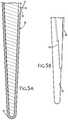
- FIG. 5Ais a detailed cross-sectional view of a portion of a needle showing a groove following the shank of the needle to receive the thread electrode, according to an aspect of the disclosure.
- FIG. 5Bis a detailed view of a portion of an alternative needle having a slot for holding the thread electrode, according to an aspect of the disclosure.
- Electrode assembly 10for use in neurological monitoring.
- Electrode assembly 10comprises a housing 20 , a needle 30 , and a thread electrode 40 . It may include a protective cover 50 , and it may also include a spring 60 and a latch 70 .
- Housing 20is a generally closed container having an interior 22 and may be cylindrical in shape and it has an opening 24 .
- Needle 30is dimensioned to fit within housing 20 and has a first end 32 and a second end 34 . Needle 30 has a retracted position when inside housing 20 and an extended position when needle 30 extends from housing 20 through the opening 24 . In the retracted position, as seen in FIG. 2C , first end 32 of needle 30 is positioned in interior 22 of housing 20 and near opening 24 of housing 20 , and second end 34 of needle 30 is positioned farther in interior 22 of housing 20 and away from opening 24 . When needle 30 is in its extended position, as seen in FIGS.
- first end 32 of needle 30extends through opening 24 and outside housing 20
- second end 34is in interior 22 of housing 20
- a protective cover 50fits to housing 20 covering opening 24 , and may be used to cover needle 30 when needle 30 is in its extended position, as shown in FIG. 1 and prior to and subsequent to use of needle 30 to deliver thread electrode 40 , as shown in FIG. 2A .
- Protective cover 50prevents “needle stick” when needle 30 is in its extended position.
- Thread electrode 40has a first end 42 and a second end 44 .
- needle 30is operable to carry first end 42 of thread electrode 40 when needle 30 moves from its retracted position to its extended position with first end 42 of thread electrode 40 and to yield up or release thread electrode 40 when first end 42 of needle 30 moves to its retracted position from its extended position after penetrating the body 80 of a patient.
- Thread electrode 40may comprise a conductive coating over a substrate, and the substrate may be non-conducting, such as a polymer or natural fiber.
- Thread electrode 40may be made of thin stainless steel. For example, fibers may be twisted with a stainless steel fiber less than 12 microns in diameter that is very pliable and very strong.
- natural or synthetic fiberscan be coated or electroplated in metals such as aluminum or magnesium. A fiber surface can be softened by heat so that it can capture electrically conductive carbon particles sprayed onto it.
- Electrically conductive thread electrodescan also be made by embedding conductive metal particles into a non-conductive fiber matrix.
- a conductive thread made of copper coated substrateuses much less copper than a copper wire, which improves the compatibility of threat electrodes to the effects of CT scans and MRIs.
- Electrode assembly 10may also include a connector 90 attached to second end 44 of thread electrode 40 , such as a DIN 42 802 standard connector, which is well-known in neurological monitoring and which enables thread electrode 40 to be connected directly into an amplifier (not shown), for example.
- a connector 90 attached to second end 44 of thread electrode 40such as a DIN 42 802 standard connector, which is well-known in neurological monitoring and which enables thread electrode 40 to be connected directly into an amplifier (not shown), for example.
- needle 30may have a groove 36 formed therein dimensioned to receive first end 42 of thread electrode 40 .
- Groove 36is dimensioned to receive first end 42 and to hold first end 42 , when needle 30 carries thread electrode into body 80 by yielding first end 42 on exit from body 80 as the friction and pressure of the inside of the path formed when needle 30 is inserted into body 80 exceeds the resistance applied to first end 42 by groove 36
- needle 30may have a slot 38 , as seen in FIG. 5B , formed near first end 32 and which is formed and dimensioned to push thread electrode 40 when needle 30 in inserted into body 80 and yield up thread electrode 40 when needle 30 is removed. Thread electrode 40 placed in slot 38 and is easily driven into body 80 by first end 32 of needle 30 and easily released when needle 30 is removed.
- Electrode assembly 10includes spring 60 secured in interior 22 of housing 20 ,
- Spring 60may be an extension spring and a first end 62 of spring 60 is attached to second end 34 of needle and a second end 64 of spring is attached to housing 20 .
- Spring 60holds needle 30 in interior 22 of housing 20 . Needle 30 may be pulled to its extended position against the urging of spring 60 .
- Latch 70is used to pull first end 32 of needle 30 to the extended position and with it first end 62 of spring 60 .
- latch 70has an unlocked position 72 and a locked position 74 .
- Latch 70may be placed in locked position 74 ( FIG. 2B ) when needle 30 has been moved to second end 34 , and needle 30 will remain there, with spring 60 extended until latch 70 is moved to its unlocked position 72 ( FIG. 2C ) and released, whereupon needle 30 returns to its retracted position inside housing 20 when urged by spring 60 .
- protective cover 50When needle 30 is in its extended position as shown in FIG. 1 , protective cover 50 is used to guard against needle stick. When needle 30 is to be inserted into body 80 , protective cover 50 is removed (see FIGS. 2 and 3 ) and needle 30 may then be inserted. First end 42 of thread electrode 40 is in position in groove 36 (or slot 38 ) of first end 42 of needle 30 , as best seen in FIGS. 2A and 5A . When needle 30 is in its extended position and latch 70 is in its locked position 74 , needle 30 may be inserted into body 80 , as shown in FIG. 3 .
- latch 70may then be moved to its unlocked position 72 , whereupon spring 60 pulls needle 30 into housing 20 when moving to its retracted position in housing 20 , yielding up thread electrode 40 to the body 80 of the patient, as seen in FIG. 4 .
- Thread electrode 40may easily be removed from the patient's body 80 by pulling thread electrode 40 from body 80 .
Landscapes
- Health & Medical Sciences (AREA)
- Life Sciences & Earth Sciences (AREA)
- Surgery (AREA)
- Engineering & Computer Science (AREA)
- General Health & Medical Sciences (AREA)
- Veterinary Medicine (AREA)
- Biomedical Technology (AREA)
- Heart & Thoracic Surgery (AREA)
- Medical Informatics (AREA)
- Molecular Biology (AREA)
- Public Health (AREA)
- Animal Behavior & Ethology (AREA)
- Pathology (AREA)
- Biophysics (AREA)
- Physics & Mathematics (AREA)
- Neurology (AREA)
- Neurosurgery (AREA)
- Physiology (AREA)
- Nuclear Medicine, Radiotherapy & Molecular Imaging (AREA)
- Electrotherapy Devices (AREA)
Abstract
Description
Claims (14)
Priority Applications (1)
| Application Number | Priority Date | Filing Date | Title |
|---|---|---|---|
| US15/696,850US10624548B2 (en) | 2016-09-09 | 2017-09-06 | Electrode assembly with thread electrode |
Applications Claiming Priority (2)
| Application Number | Priority Date | Filing Date | Title |
|---|---|---|---|
| US201662385434P | 2016-09-09 | 2016-09-09 | |
| US15/696,850US10624548B2 (en) | 2016-09-09 | 2017-09-06 | Electrode assembly with thread electrode |
Publications (2)
| Publication Number | Publication Date |
|---|---|
| US20180353132A1 US20180353132A1 (en) | 2018-12-13 |
| US10624548B2true US10624548B2 (en) | 2020-04-21 |
Family
ID=64562380
Family Applications (1)
| Application Number | Title | Priority Date | Filing Date |
|---|---|---|---|
| US15/696,850Active2038-09-01US10624548B2 (en) | 2016-09-09 | 2017-09-06 | Electrode assembly with thread electrode |
Country Status (1)
| Country | Link |
|---|---|
| US (1) | US10624548B2 (en) |
Cited By (1)
| Publication number | Priority date | Publication date | Assignee | Title |
|---|---|---|---|---|
| US11974778B1 (en) | 2023-04-26 | 2024-05-07 | The Florida International University Board Of Trustees | Systems and methods for implanting longitudinal intrafascicular electrodes |
Families Citing this family (1)
| Publication number | Priority date | Publication date | Assignee | Title |
|---|---|---|---|---|
| CN115530837A (en)* | 2022-09-15 | 2022-12-30 | 清华大学 | Flexible electrode device |
Citations (15)
| Publication number | Priority date | Publication date | Assignee | Title |
|---|---|---|---|---|
| US4417581A (en)* | 1979-05-23 | 1983-11-29 | The University Of Florida | Corneal electrode for electroretinography |
| US5645076A (en) | 1991-08-14 | 1997-07-08 | Yoon; Inbae | Automatic retractable safety penetrating instrument |
| US6547762B1 (en) | 1999-05-13 | 2003-04-15 | Mdc Investment Holdings, Inc. | Retractable needle medical device |
| US6652519B2 (en) | 2000-11-10 | 2003-11-25 | Thermo-Med 2000 Kft | Electrode needle with radiofrequency active filament |
| US20050085807A1 (en) | 2002-04-23 | 2005-04-21 | Andrea Venturelli | Instrument with at least two active radio-frequency wires for treatment of tumours |
| US6912424B2 (en)* | 1999-12-01 | 2005-06-28 | Meagan, Medical, Inc. | Apparatus and method for coupling therapeutic and/or monitoring equipment to a patient |
| US20060161058A1 (en) | 2005-01-18 | 2006-07-20 | Ives John R | Technique for design, and placement, of a subdermal Ag-Ag/Cl biopotential electrode |
| US20080127978A1 (en) | 2006-12-05 | 2008-06-05 | Benjamin Rubin | Pressure support system with dry electrode sleep staging device |
| US20120296230A1 (en)* | 2009-05-11 | 2012-11-22 | Timothy Taylor Davis | Neurologic monitoring system and method |
| US8855736B2 (en) | 2010-08-05 | 2014-10-07 | Richard A. Jaffe | Safety transcutaneous electrode |
| US20150141786A1 (en)* | 2013-11-15 | 2015-05-21 | Case Western Reserve University | Interfacing With The Peripheral Nervous System (PNS) Using Targeted Fascicular Interface Device |
| US20160096015A1 (en) | 2006-06-12 | 2016-04-07 | Region Hovedstaden V/Herlev Hospital | Electrode introducer device |
| WO2016126340A2 (en) | 2014-12-23 | 2016-08-11 | The Regents Of The University Of California | Methods, compositions, and systems for device implantation |
| US20170049991A1 (en) | 2011-12-07 | 2017-02-23 | Traumatek Solutions, B.V. | Devices and methods for endovascular access and therapy |
| US20170182312A1 (en)* | 2014-04-08 | 2017-06-29 | Case Western Reserve University | Neural electrodes and methods for implanting same |
- 2017
- 2017-09-06USUS15/696,850patent/US10624548B2/enactiveActive
Patent Citations (15)
| Publication number | Priority date | Publication date | Assignee | Title |
|---|---|---|---|---|
| US4417581A (en)* | 1979-05-23 | 1983-11-29 | The University Of Florida | Corneal electrode for electroretinography |
| US5645076A (en) | 1991-08-14 | 1997-07-08 | Yoon; Inbae | Automatic retractable safety penetrating instrument |
| US6547762B1 (en) | 1999-05-13 | 2003-04-15 | Mdc Investment Holdings, Inc. | Retractable needle medical device |
| US6912424B2 (en)* | 1999-12-01 | 2005-06-28 | Meagan, Medical, Inc. | Apparatus and method for coupling therapeutic and/or monitoring equipment to a patient |
| US6652519B2 (en) | 2000-11-10 | 2003-11-25 | Thermo-Med 2000 Kft | Electrode needle with radiofrequency active filament |
| US20050085807A1 (en) | 2002-04-23 | 2005-04-21 | Andrea Venturelli | Instrument with at least two active radio-frequency wires for treatment of tumours |
| US20060161058A1 (en) | 2005-01-18 | 2006-07-20 | Ives John R | Technique for design, and placement, of a subdermal Ag-Ag/Cl biopotential electrode |
| US20160096015A1 (en) | 2006-06-12 | 2016-04-07 | Region Hovedstaden V/Herlev Hospital | Electrode introducer device |
| US20080127978A1 (en) | 2006-12-05 | 2008-06-05 | Benjamin Rubin | Pressure support system with dry electrode sleep staging device |
| US20120296230A1 (en)* | 2009-05-11 | 2012-11-22 | Timothy Taylor Davis | Neurologic monitoring system and method |
| US8855736B2 (en) | 2010-08-05 | 2014-10-07 | Richard A. Jaffe | Safety transcutaneous electrode |
| US20170049991A1 (en) | 2011-12-07 | 2017-02-23 | Traumatek Solutions, B.V. | Devices and methods for endovascular access and therapy |
| US20150141786A1 (en)* | 2013-11-15 | 2015-05-21 | Case Western Reserve University | Interfacing With The Peripheral Nervous System (PNS) Using Targeted Fascicular Interface Device |
| US20170182312A1 (en)* | 2014-04-08 | 2017-06-29 | Case Western Reserve University | Neural electrodes and methods for implanting same |
| WO2016126340A2 (en) | 2014-12-23 | 2016-08-11 | The Regents Of The University Of California | Methods, compositions, and systems for device implantation |
Cited By (1)
| Publication number | Priority date | Publication date | Assignee | Title |
|---|---|---|---|---|
| US11974778B1 (en) | 2023-04-26 | 2024-05-07 | The Florida International University Board Of Trustees | Systems and methods for implanting longitudinal intrafascicular electrodes |
Also Published As
| Publication number | Publication date |
|---|---|
| US20180353132A1 (en) | 2018-12-13 |
Similar Documents
| Publication | Publication Date | Title |
|---|---|---|
| US7950971B2 (en) | Electrical connector apparatus and methods | |
| CA2575313C (en) | Mri systems having mri compatible universal delivery cannulas with cooperating mri antenna probes and related systems and methods | |
| US20180145443A1 (en) | Connector and methods for making and using the connector | |
| US6606521B2 (en) | Implantable medical lead | |
| US4624266A (en) | Introducer tool for screw-in lead | |
| US5375596A (en) | Method and apparatus for determining the position of catheters, tubes, placement guidewires and implantable ports within biological tissue | |
| US10624548B2 (en) | Electrode assembly with thread electrode | |
| US6708051B1 (en) | FMRI compatible electrode and electrode placement techniques | |
| US20070088418A1 (en) | Delivery system for implantable biostimulator | |
| US20040181177A1 (en) | Guidewire and connector therefor | |
| CN105120742A (en) | Techniques for natural user interface input based on context | |
| AU2008202498A1 (en) | Magnetic resonance probes | |
| US9585618B2 (en) | Nerve location detection | |
| JP2002529132A (en) | Electrode and electrode arrangement method suitable for functional magnetic resonance imaging apparatus | |
| CA2712440A1 (en) | Device and method for positioning a cannula for a nerve block | |
| EP3744242A1 (en) | Brain navigation lead | |
| WO2014110117A1 (en) | An active tracking system and method for mri | |
| US5170788A (en) | Needle electrode and method of assembly thereof | |
| US7440789B2 (en) | Electrode structure for measuring electrical responses from the human body | |
| CN112074230A (en) | Connection system for establishing an electrical connection across a sterile field and method therefor | |
| US9212981B2 (en) | Feedback system and method for assessing fixation and stability of implantable leads | |
| US8644955B2 (en) | Controller for a medical lead delivery device | |
| CA2655515A1 (en) | Temperature sensing within a patient during mr imaging | |
| US10213615B2 (en) | System and method for micromagnetic stimulation of the central nervous system | |
| JP6134716B2 (en) | Invasive or non-invasive instruments for use in MR devices |
Legal Events
| Date | Code | Title | Description |
|---|---|---|---|
| AS | Assignment | Owner name:RHYTHMLINK INTERNATIONAL, LLC, SOUTH CAROLINA Free format text:ASSIGNMENT OF ASSIGNORS INTEREST;ASSIGNOR:KEISLER, GERALD, MR.;REEL/FRAME:043508/0308 Effective date:20170906 | |
| FEPP | Fee payment procedure | Free format text:ENTITY STATUS SET TO UNDISCOUNTED (ORIGINAL EVENT CODE: BIG.); ENTITY STATUS OF PATENT OWNER: LARGE ENTITY Free format text:ENTITY STATUS SET TO UNDISCOUNTED (ORIGINAL EVENT CODE: BIG.); ENTITY STATUS OF PATENT OWNER: SMALL ENTITY | |
| FEPP | Fee payment procedure | Free format text:ENTITY STATUS SET TO SMALL (ORIGINAL EVENT CODE: SMAL); ENTITY STATUS OF PATENT OWNER: LARGE ENTITY Free format text:ENTITY STATUS SET TO SMALL (ORIGINAL EVENT CODE: SMAL); ENTITY STATUS OF PATENT OWNER: SMALL ENTITY | |
| STPP | Information on status: patent application and granting procedure in general | Free format text:DOCKETED NEW CASE - READY FOR EXAMINATION | |
| AS | Assignment | Owner name:MADISON CAPITAL FUNDING LLC, AS AGENT, ILLINOIS Free format text:SECURITY INTEREST;ASSIGNOR:RHYTHMLINK INTERNATIONAL, LLC;REEL/FRAME:048380/0881 Effective date:20190219 | |
| STPP | Information on status: patent application and granting procedure in general | Free format text:NON FINAL ACTION MAILED | |
| STPP | Information on status: patent application and granting procedure in general | Free format text:NOTICE OF ALLOWANCE MAILED -- APPLICATION RECEIVED IN OFFICE OF PUBLICATIONS | |
| STCF | Information on status: patent grant | Free format text:PATENTED CASE | |
| FEPP | Fee payment procedure | Free format text:ENTITY STATUS SET TO UNDISCOUNTED (ORIGINAL EVENT CODE: BIG.); ENTITY STATUS OF PATENT OWNER: LARGE ENTITY | |
| AS | Assignment | Owner name:APOGEM CAPITAL LLC, AS ADMINISTRATIVE AGENT, ILLINOIS Free format text:SECURITY INTEREST;ASSIGNOR:MADISON CAPITAL FUNDING LLC, AS ADMINISTRATIVE AGENT;REEL/FRAME:059563/0359 Effective date:20220401 | |
| AS | Assignment | Owner name:APOGEM CAPITAL LLC, AGENT, ILLINOIS Free format text:SECURITY INTEREST;ASSIGNOR:RHYTHMLINK INTERNATIONAL, LLC;REEL/FRAME:062985/0933 Effective date:20230315 Owner name:RHYTHMLINK INTERNATIONAL, LLC, SOUTH CAROLINA Free format text:RELEASE BY SECURED PARTY;ASSIGNOR:APOGEM CAPITAL FUNDING LLC, AS SUCCESSOR AGENT;REEL/FRAME:062995/0706 Effective date:20230315 | |
| MAFP | Maintenance fee payment | Free format text:PAYMENT OF MAINTENANCE FEE, 4TH YEAR, LARGE ENTITY (ORIGINAL EVENT CODE: M1551); ENTITY STATUS OF PATENT OWNER: LARGE ENTITY Year of fee payment:4 |