US10624471B2 - Security system for displaying objects - Google Patents
Security system for displaying objectsDownload PDFInfo
- Publication number
- US10624471B2 US10624471B2US15/948,637US201815948637AUS10624471B2US 10624471 B2US10624471 B2US 10624471B2US 201815948637 AUS201815948637 AUS 201815948637AUS 10624471 B2US10624471 B2US 10624471B2
- Authority
- US
- United States
- Prior art keywords
- assembly
- clamp
- anchor
- security system
- opposed
- Prior art date
- Legal status (The legal status is an assumption and is not a legal conclusion. Google has not performed a legal analysis and makes no representation as to the accuracy of the status listed.)
- Active
Links
Images


Classifications
- A—HUMAN NECESSITIES
- A47—FURNITURE; DOMESTIC ARTICLES OR APPLIANCES; COFFEE MILLS; SPICE MILLS; SUCTION CLEANERS IN GENERAL
- A47F—SPECIAL FURNITURE, FITTINGS, OR ACCESSORIES FOR SHOPS, STOREHOUSES, BARS, RESTAURANTS OR THE LIKE; PAYING COUNTERS
- A47F3/00—Show cases or show cabinets
- A47F3/002—Devices for protection against sunlight or theft
- E—FIXED CONSTRUCTIONS
- E05—LOCKS; KEYS; WINDOW OR DOOR FITTINGS; SAFES
- E05B—LOCKS; ACCESSORIES THEREFOR; HANDCUFFS
- E05B73/00—Devices for locking portable objects against unauthorised removal; Miscellaneous locking devices
- F—MECHANICAL ENGINEERING; LIGHTING; HEATING; WEAPONS; BLASTING
- F16—ENGINEERING ELEMENTS AND UNITS; GENERAL MEASURES FOR PRODUCING AND MAINTAINING EFFECTIVE FUNCTIONING OF MACHINES OR INSTALLATIONS; THERMAL INSULATION IN GENERAL
- F16M—FRAMES, CASINGS OR BEDS OF ENGINES, MACHINES OR APPARATUS, NOT SPECIFIC TO ENGINES, MACHINES OR APPARATUS PROVIDED FOR ELSEWHERE; STANDS; SUPPORTS
- F16M11/00—Stands or trestles as supports for apparatus or articles placed thereon ; Stands for scientific apparatus such as gravitational force meters
- F16M11/02—Heads
- F16M11/04—Means for attachment of apparatus; Means allowing adjustment of the apparatus relatively to the stand
- F16M11/041—Allowing quick release of the apparatus
- F—MECHANICAL ENGINEERING; LIGHTING; HEATING; WEAPONS; BLASTING
- F16—ENGINEERING ELEMENTS AND UNITS; GENERAL MEASURES FOR PRODUCING AND MAINTAINING EFFECTIVE FUNCTIONING OF MACHINES OR INSTALLATIONS; THERMAL INSULATION IN GENERAL
- F16M—FRAMES, CASINGS OR BEDS OF ENGINES, MACHINES OR APPARATUS, NOT SPECIFIC TO ENGINES, MACHINES OR APPARATUS PROVIDED FOR ELSEWHERE; STANDS; SUPPORTS
- F16M11/00—Stands or trestles as supports for apparatus or articles placed thereon ; Stands for scientific apparatus such as gravitational force meters
- F16M11/02—Heads
- F16M11/04—Means for attachment of apparatus; Means allowing adjustment of the apparatus relatively to the stand
- F16M11/043—Allowing translations
- F—MECHANICAL ENGINEERING; LIGHTING; HEATING; WEAPONS; BLASTING
- F16—ENGINEERING ELEMENTS AND UNITS; GENERAL MEASURES FOR PRODUCING AND MAINTAINING EFFECTIVE FUNCTIONING OF MACHINES OR INSTALLATIONS; THERMAL INSULATION IN GENERAL
- F16M—FRAMES, CASINGS OR BEDS OF ENGINES, MACHINES OR APPARATUS, NOT SPECIFIC TO ENGINES, MACHINES OR APPARATUS PROVIDED FOR ELSEWHERE; STANDS; SUPPORTS
- F16M11/00—Stands or trestles as supports for apparatus or articles placed thereon ; Stands for scientific apparatus such as gravitational force meters
- F16M11/02—Heads
- F16M11/04—Means for attachment of apparatus; Means allowing adjustment of the apparatus relatively to the stand
- F16M11/06—Means for attachment of apparatus; Means allowing adjustment of the apparatus relatively to the stand allowing pivoting
- F16M11/12—Means for attachment of apparatus; Means allowing adjustment of the apparatus relatively to the stand allowing pivoting in more than one direction
- F—MECHANICAL ENGINEERING; LIGHTING; HEATING; WEAPONS; BLASTING
- F16—ENGINEERING ELEMENTS AND UNITS; GENERAL MEASURES FOR PRODUCING AND MAINTAINING EFFECTIVE FUNCTIONING OF MACHINES OR INSTALLATIONS; THERMAL INSULATION IN GENERAL
- F16M—FRAMES, CASINGS OR BEDS OF ENGINES, MACHINES OR APPARATUS, NOT SPECIFIC TO ENGINES, MACHINES OR APPARATUS PROVIDED FOR ELSEWHERE; STANDS; SUPPORTS
- F16M13/00—Other supports for positioning apparatus or articles; Means for steadying hand-held apparatus or articles
- F16M13/02—Other supports for positioning apparatus or articles; Means for steadying hand-held apparatus or articles for supporting on, or attaching to, an object, e.g. tree, gate, window-frame, cycle
- A—HUMAN NECESSITIES
- A47—FURNITURE; DOMESTIC ARTICLES OR APPLIANCES; COFFEE MILLS; SPICE MILLS; SUCTION CLEANERS IN GENERAL
- A47F—SPECIAL FURNITURE, FITTINGS, OR ACCESSORIES FOR SHOPS, STOREHOUSES, BARS, RESTAURANTS OR THE LIKE; PAYING COUNTERS
- A47F7/00—Show stands, hangers, or shelves, adapted for particular articles or materials
- A47F7/02—Show stands, hangers, or shelves, adapted for particular articles or materials for jewellery, dentures, watches, eye-glasses, lenses, or the like
- A47F7/024—Show stands, hangers, or shelves, adapted for particular articles or materials for jewellery, dentures, watches, eye-glasses, lenses, or the like with provisions for preventing unauthorised removal
- A47F7/0246—Show stands, hangers, or shelves, adapted for particular articles or materials for jewellery, dentures, watches, eye-glasses, lenses, or the like with provisions for preventing unauthorised removal for rectangular articles, e.g. books, cassettes
- E—FIXED CONSTRUCTIONS
- E05—LOCKS; KEYS; WINDOW OR DOOR FITTINGS; SAFES
- E05B—LOCKS; ACCESSORIES THEREFOR; HANDCUFFS
- E05B65/00—Locks or fastenings for special use
- E—FIXED CONSTRUCTIONS
- E05—LOCKS; KEYS; WINDOW OR DOOR FITTINGS; SAFES
- E05B—LOCKS; ACCESSORIES THEREFOR; HANDCUFFS
- E05B73/00—Devices for locking portable objects against unauthorised removal; Miscellaneous locking devices
- E05B73/0005—Devices for locking portable objects against unauthorised removal; Miscellaneous locking devices using chains, cables or the like
- F—MECHANICAL ENGINEERING; LIGHTING; HEATING; WEAPONS; BLASTING
- F16—ENGINEERING ELEMENTS AND UNITS; GENERAL MEASURES FOR PRODUCING AND MAINTAINING EFFECTIVE FUNCTIONING OF MACHINES OR INSTALLATIONS; THERMAL INSULATION IN GENERAL
- F16B—DEVICES FOR FASTENING OR SECURING CONSTRUCTIONAL ELEMENTS OR MACHINE PARTS TOGETHER, e.g. NAILS, BOLTS, CIRCLIPS, CLAMPS, CLIPS OR WEDGES; JOINTS OR JOINTING
- F16B2/00—Friction-grip releasable fastenings
- F16B2/02—Clamps, i.e. with gripping action effected by positive means other than the inherent resistance to deformation of the material of the fastening
- F16B2/06—Clamps, i.e. with gripping action effected by positive means other than the inherent resistance to deformation of the material of the fastening external, i.e. with contracting action
- F16B2/065—Clamps, i.e. with gripping action effected by positive means other than the inherent resistance to deformation of the material of the fastening external, i.e. with contracting action using screw-thread elements
- F—MECHANICAL ENGINEERING; LIGHTING; HEATING; WEAPONS; BLASTING
- F16—ENGINEERING ELEMENTS AND UNITS; GENERAL MEASURES FOR PRODUCING AND MAINTAINING EFFECTIVE FUNCTIONING OF MACHINES OR INSTALLATIONS; THERMAL INSULATION IN GENERAL
- F16B—DEVICES FOR FASTENING OR SECURING CONSTRUCTIONAL ELEMENTS OR MACHINE PARTS TOGETHER, e.g. NAILS, BOLTS, CIRCLIPS, CLAMPS, CLIPS OR WEDGES; JOINTS OR JOINTING
- F16B2/00—Friction-grip releasable fastenings
- F16B2/02—Clamps, i.e. with gripping action effected by positive means other than the inherent resistance to deformation of the material of the fastening
- F16B2/06—Clamps, i.e. with gripping action effected by positive means other than the inherent resistance to deformation of the material of the fastening external, i.e. with contracting action
- F16B2/12—Clamps, i.e. with gripping action effected by positive means other than the inherent resistance to deformation of the material of the fastening external, i.e. with contracting action using sliding jaws
- F—MECHANICAL ENGINEERING; LIGHTING; HEATING; WEAPONS; BLASTING
- F16—ENGINEERING ELEMENTS AND UNITS; GENERAL MEASURES FOR PRODUCING AND MAINTAINING EFFECTIVE FUNCTIONING OF MACHINES OR INSTALLATIONS; THERMAL INSULATION IN GENERAL
- F16B—DEVICES FOR FASTENING OR SECURING CONSTRUCTIONAL ELEMENTS OR MACHINE PARTS TOGETHER, e.g. NAILS, BOLTS, CIRCLIPS, CLAMPS, CLIPS OR WEDGES; JOINTS OR JOINTING
- F16B5/00—Joining sheets or plates, e.g. panels, to one another or to strips or bars parallel to them
- F16B5/02—Joining sheets or plates, e.g. panels, to one another or to strips or bars parallel to them by means of fastening members using screw-thread
- F16B5/0216—Joining sheets or plates, e.g. panels, to one another or to strips or bars parallel to them by means of fastening members using screw-thread the position of the plates to be connected being adjustable
- F16B5/0233—Joining sheets or plates, e.g. panels, to one another or to strips or bars parallel to them by means of fastening members using screw-thread the position of the plates to be connected being adjustable allowing for adjustment perpendicular to the plane of the plates
- F—MECHANICAL ENGINEERING; LIGHTING; HEATING; WEAPONS; BLASTING
- F16—ENGINEERING ELEMENTS AND UNITS; GENERAL MEASURES FOR PRODUCING AND MAINTAINING EFFECTIVE FUNCTIONING OF MACHINES OR INSTALLATIONS; THERMAL INSULATION IN GENERAL
- F16M—FRAMES, CASINGS OR BEDS OF ENGINES, MACHINES OR APPARATUS, NOT SPECIFIC TO ENGINES, MACHINES OR APPARATUS PROVIDED FOR ELSEWHERE; STANDS; SUPPORTS
- F16M11/00—Stands or trestles as supports for apparatus or articles placed thereon ; Stands for scientific apparatus such as gravitational force meters
- F16M11/20—Undercarriages with or without wheels
- F16M11/2007—Undercarriages with or without wheels comprising means allowing pivoting adjustment
- F16M11/2014—Undercarriages with or without wheels comprising means allowing pivoting adjustment around a vertical axis
- F—MECHANICAL ENGINEERING; LIGHTING; HEATING; WEAPONS; BLASTING
- F16—ENGINEERING ELEMENTS AND UNITS; GENERAL MEASURES FOR PRODUCING AND MAINTAINING EFFECTIVE FUNCTIONING OF MACHINES OR INSTALLATIONS; THERMAL INSULATION IN GENERAL
- F16M—FRAMES, CASINGS OR BEDS OF ENGINES, MACHINES OR APPARATUS, NOT SPECIFIC TO ENGINES, MACHINES OR APPARATUS PROVIDED FOR ELSEWHERE; STANDS; SUPPORTS
- F16M11/00—Stands or trestles as supports for apparatus or articles placed thereon ; Stands for scientific apparatus such as gravitational force meters
- F16M11/20—Undercarriages with or without wheels
- F16M11/24—Undercarriages with or without wheels changeable in height or length of legs, also for transport only, e.g. by means of tubes screwed into each other
- F—MECHANICAL ENGINEERING; LIGHTING; HEATING; WEAPONS; BLASTING
- F16—ENGINEERING ELEMENTS AND UNITS; GENERAL MEASURES FOR PRODUCING AND MAINTAINING EFFECTIVE FUNCTIONING OF MACHINES OR INSTALLATIONS; THERMAL INSULATION IN GENERAL
- F16M—FRAMES, CASINGS OR BEDS OF ENGINES, MACHINES OR APPARATUS, NOT SPECIFIC TO ENGINES, MACHINES OR APPARATUS PROVIDED FOR ELSEWHERE; STANDS; SUPPORTS
- F16M2200/00—Details of stands or supports
- F16M2200/02—Locking means
Definitions
- the present disclosurerelates generally to a security system for securely displaying objects.
- a mount assembly and a security system for securely displaying objectsare provided.
- a mount assemblyfor securing to an object, comprising opposed clamp members for engaging the object, and a clamp assembly for releasably securing the clamp members, the clamp assembly including opposed surfaces defining a passage for receiving ends of the opposed clamp members, the opposed surfaces being movable to each other to secure the clamp members.
- a security systemcomprising a mount assembly for securing to an object and an anchor assembly for securing to a support member, the mount assembly being releasably lockable to the anchor assembly, wherein when the mount assembly is locked to the anchor assembly the object cannot be released from the mount assembly.
- a mount assemblyfor securing to an object, comprising opposed clamp members for engaging the object, a clamp assembly for releasably securing the clamp members, and a clamp member slidably received on the clamp assembly for engaging a back of the object when the opposed clamp members engage a front of the object.
- a cut resistant cablecomprising: a plurality of conductors, surrounded by an overbraid comprising strands of steel and Kvelar.
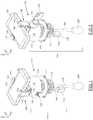
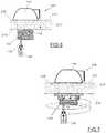
- FIGS. 1 and 2are perspective views of a security system according to an example embodiment
- FIG. 3is an exploded perspective view of the security system of FIGS. 1 and 2 ;
- FIG. 3Ais an enlarged view of part of FIG. 3 ;
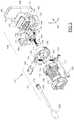
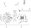
- FIG. 4is an exploded front view of the security system of FIGS. 1 and 2 ;
- FIG. 5is an exploded side view of the security system of FIGS. 1 and 2 ;
- FIGS. 6 and 7are side views illustrating attachment of the anchor assembly of the security system of FIG. 1 to a support member
- FIGS. 8 and 9are perspective views illustrating assembly of the mount assembly of the security system of FIG. 1 ;
- FIG. 10is a bottom view of a clamp assembly of the mount assembly of the security system of FIG. 1 ;
- FIG. 11is a schematic side view of the clamp assembly of FIG. 10 ;
- FIG. 12is an end view of the a mount assembly of the security system of FIG. 1 attached to an object;
- FIG. 12Ais an enlarged partial view of FIG. 12 ;
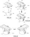
- FIGS. 13 and 14are perspective views illustrating mounting of the mount assembly to the anchor assembly of the security system of FIG. 1 ;
- FIG. 15are perspective views illustrating pivoting of the mount assembly relative to the anchor assembly of the security system of FIG. 1 ;
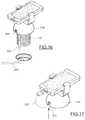
- FIGS. 16 and 17are perspective views illustrating a security system configured for use with a third party power supply cord, according to an example embodiment
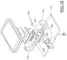
- FIG. 18is an exploded perspective view of a further example embodiment of a security system
- FIGS. 19 and 20are perspective views of a further example embodiment of a security system in retracted and extended positions, respectively;
- FIG. 21is an exploded perspective view of the security system of FIGS. 19 and 20 ;
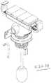
- FIGS. 22 to 29illustrate a recoiler for use with the security system of FIGS. 19 and 20 ;
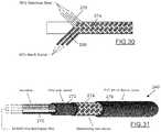
- FIGS. 30 and 31illustrate a powered cable for use with the recoiler of the security system of FIGS. 19 and 20 ;
- FIG. 32is an exploded front view of a security system according to another example embodiment.
- FIG. 33is a side view of a mounting system of the security system of FIG. 32 ;
- FIG. 34is a perspective exploded view of the mounting system of FIG. 33 ;
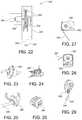
- FIG. 35Ais an exploded partial perspective view of a security system according to another example embodiment
- FIG. 35Bis a perspective view of the security system of FIG. 35A ;
- FIG. 36is a perspective exploded view of a further embodiment of a security system
- FIG. 37is an exploded partial perspective view of a security system according to another example embodiment.
- FIG. 38is a perspective view of the security system of FIG. 37 ;
- FIG. 39is an exploded partial perspective view of a security system according to another example embodiment.
- FIG. 40is a perspective view of the security system of FIG. 39 ;
- FIG. 41is a front perspective view of a mount assembly according to a further example embodiment.
- FIG. 42is a front perspective view of selected elements of the mount assembly of FIG. 41 ;
- FIG. 43is a front exploded view of selected elements of the mount assembly of FIG. 41 .
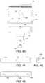
- FIG. 44is a front view of a clamp plate of the mount assembly of FIG. 41 ;
- FIG. 45is a bottom view of the clamp plate of FIG. 44 ;
- FIG. 46is a side end view of the clamp plate of FIG. 44 ;
- FIG. 47is a side end view of selected elements of the mount assembly of FIG. 41 .
- FIGS. 1-5illustrate an example embodiment of a security system 100 that can be used to secure an object 102 so that an individual such as a potential purchaser in a retail setting can view and interact with the object 102 but is generally prevented from removing the object 102 from its display location.
- the object 102could be a rectangular prism shaped object such as a smart phone, tablet computer, GPS receiver, personal media player, personal gaming system or other electronic device or high value ware.
- the security system 100includes an anchor assembly 104 and a movable mount assembly 106 .
- Anchor assembly 104is configured to be secured to a stationary support such as a display counter
- mount assembly 106is configured to be secured to the object 102 .
- a tether 108may be used to secure the mount assembly 106 to the anchor assembly 104 .
- the anchor assembly 104includes a cylindrical anchor member 112 that has a radial flange 130 at a forward end and from which a threaded tube 132 extends in a rearward direction.
- the threaded tube 132passes through a circular opening in a support member (such as a display counter), with the radial flange 112 resting on a surface of the support member.
- a threaded anchor plate or ring nut 110can be screwed onto threaded tube 132 to engage the opposite surface of the support member to secure the cylindrical anchor member 112 in place.
- the anchor assembly 104includes an anchor lock assembly 118 that releasably locks the mount assembly 106 to the anchor assembly 104 .
- the anchor lock assembly 118includes a rigid lock housing 119 that houses a lock device 120 that is actuated by a key 122 in the illustrated example.
- the mount assembly 106includes opposed generally L-shaped clamp members 140 that are configured to engage opposite side edges of the object 102 that is to be secured.
- L-shaped clamp members 140each have a respective arm or end 148 slidably received within a passage 146 defined within a clamp assembly 144 .
- clamp assembly 144can take a number of different configurations, in the example shown in FIG. 1-5 the clamp assembly 144 includes a first clamp plate 152 and a base member 150 , with the clamp passage 146 being defined between them.
- locking screws 154pass through holes provided in the base member 150 and corresponding slots in the clamp member ends 148 into threaded holes 156 in the first clamp plate 152 .
- locking screws 154are equipped with a security head so that a specialized tool is required to remove and tighten them. Tightening locking screws 154 draws the clamp plate 152 to the base member 150 to apply clamping force on the clamp member ends 148 , thereby securing the clamp members 140 into opposition relative to each other.
- clamp members 140can be moved towards and away from each other along the y-axis to adjust the spacing between them and then they can be secured in place by tightening locking screws 154 .
- ribs or serrationsmay be provided on one or more of the interior surfaces of clamp passage 146 or clamp member arms 148 to provide resistance against separation of the clamp members 140 when screws 154 are tightened.
- ribs or serations 141are provided on the top and bottom surfaces of the clamp member arms 148 to cooperate with corresponding ribs or serations 141 provided on the respective surfaces of clamp passage 146 .
- each clamp member 140includes an inwardly directed engagement member 142 , such as a flange or tab, that is connected by an intermediate side arm 160 in spaced opposition to clamp member arm 148 .
- Engagement members 142are used to clamp a surface of the object 102 as will be described in grater detail below.
- a rubber or resilient anti-slip pad or anti-slip coating 162may be applied to the inner surfaces of clamp member engagement member 142 and intermediate side arm 142 .
- clamp members 140 , clamp plate 152 and base member 150are all formed from steel or other metal, however alternative materials could also be used.
- clamp passage 146has a substantially rectangular cross-section that corresponds to a rectangular cross-section of the clamp member arms 158 . Accordingly, when the arms 158 of the clamp members 140 are secured in place between the clamp plate 152 and the base member 150 , movement of the clamp members 140 in each of X, Y and Z directions is prevented. Before screws 154 are tightened, the clamp assembly 144 functions to guide the clamp members 140 into the correct positioning, and once screws 154 are tightened, the clamp member arms 158 are clamped and contained in position, creating a parallel solid assembly.
- the clamp assembly base member 150also includes a central rearward protruding spigot or anchor interface 164 for engaging the anchor assembly 104 .
- the anchor interface 164is cylindrical and defines a central passage for receiving an adjustment screw 168 .
- a threaded opening 166is provided through the base member 150 within the anchor interface 164 for engaging the adjustment screw 168 .
- an opening 188is provided through the clamp plate 152 for the adjustment screw 168 , enabling the front end of the screw to press against a resilient spring plate 174 which in turn presses against, and spreads the force of screw 168 across, an object clamp member 176 .
- Object clamp member 176has a forward facing surface 180 for applying a clamping force against a back surface of the object 102 that is being secured.
- the object clamp member 176defines a rearward opening channel 178 that slidably receives the clamp assembly 144 and spring plate 174 .
- Mounting pins 182are provided on a rearward surface of the object clamp member to cooperate with corresponding holes 184 on the spring plate 174 to secure the spring plate in place on the underside of the object clamp member.
- a resilient non-slip pad or non-slip coating 186can be located on the clamp surface 180 of the object clamp 174 to help grip object 102 .
- object clamp member 176may be formed from plastic, with spring plate 174 being formed from metal.
- the anchor interface 164includes internal threads 170 at its rearwardly extending end 190 for receiving a threaded end 172 of the tether 108 .
- anchor interface 164is configured to be releasably received within a central, cylindrical opening 192 that is provided through the lock housing 119 of anchor lock assembly 118 .
- the anchor interface 164defines a radial channel 194 located forward of enlarged end 190 .
- lock device 120includes a retractable lock pin 198 which extends through radial opening 196 and into the radial channel 194 of anchor interface 164 when in an extended, locked position.
- the extending end of lock pin 198will engage the enlarged anchor interface end 190 to prevent the mount assembly 106 from being removed from the anchor lock assembly 118 .
- Key 122can be used to retract lock pin 198 from the radial channel 194 of anchor interface 164 to release the mount assembly 106 so it can be removed from the anchor lock assembly 118 .
- the lock pin 198is chamfered and spring loaded into the extended position to allow the anchor interface 164 to be inserted and snapped into a locked position in the central opening 192 without requiring actuation of key 122 , while withdrawal of the anchor interface 164 is prevented until key 122 is actuated to retract the lock pin 198 .
- the radial channel 194allows the mount assembly 106 to rotate even when the lock pin 198 prevents its removal from the anchor lock assembly 118 .
- the anchor lock assembly 118includes an indexing mechanism for controlling rotation of the mount assembly 106 .
- anchor lock assemblyincludes a pair of opposed spring loaded balls 200 that extend partially into central opening 192 to engage the enlarged end 190 of the mount assembly anchor interface 164 .
- Radial index notches 204are provided on the mount assembly anchor interface 164 for receiving the spring loaded balls 200 , allowing the mount assembly 106 to snap into and out of biased positions as it rotates about the Z axis, with spring loaded balls 200 acting as cam followers and the notched radial outer surface of the enlarged end 190 acting as a cam. Such indexing may be used for example to facilitate rotation of mount assembly 106 ninety degrees between a “landscape” and “portrait” viewing positions for object 102 .
- the balls 200are each biased partially into central opening 192 by a respective spring 202 that is held in place within the lock housing 119 by a respective spring retaining member 124 .
- one or more stop members 195are located in radial channel 194 for cooperating with lock pin 198 on the anchor interface 164 in order to prevent the mount assembly 104 from being rotated beyond a threshold amount, thus protecting any power cord attachment to the mounted device.
- stop members 195are positioned to prevent the mount assembly 104 from being rotated more than 180 degrees.
- the indexingcould be used to allow the mount assembly 106 to “click” into a portrait position, be rotated 90 degrees counter-clockwise to “click” into a first landscape position, then be rotated 180 degrees clockwise to “click” into a second landscape position, with the stop members 195 preventing counter-clockwise rotation beyond the first landscape position and clockwise rotation beyond the second landscape position.
- the anchor assembly 104includes a power/data line 116 that extends internally within the cylindrical anchor member 112 and which has a connector 128 at one end for connecting to a power and/or data source and a further connector 126 at the other end 126 for connecting to a line to object 102 .
- lock housing 119defines an external opening 206 that houses connector 126 .
- Connectors 126 , 128could for example be mini-USB male or female plug style connectors.
- connector 126is a female connector rigidly secured in place to the lock housing 119 such that a short power line can be connected from lock housing 119 to the object 102 to periodically charge the object 102 as required.
- An initial stepinvolves assembling the anchor assembly 104 by securing the anchor lock assembly 118 to the cylindrical anchor member 112 .
- the anchor lock assemblycan take a number of alternative configurations, in the illustrated embodiment, the anchor lock assembly 118 is secured to the anchor member flange 130 by screws 114 which pass through corresponding openings in the flange 130 and into respective threaded holes in the lock housing 119 .
- the assembled anchor assembly 104can then be mounted to a support member 210 as illustrated in FIGS. 6 and 7 (also shown in dashed lines in FIG. 5 ).
- Support member 210could for example be a display counter in a retail location and be configured to support multiple security systems 100 in tandem.
- An opening 216is provided through the support member 210 that is larger than the circumference of the threaded region 132 of the cylindrical anchor member 112 but smaller than the flange 130 , such that the threaded region 132 is inserted into the opening 216 until flange 130 engages a forward surface 212 of the support member 210 .
- the anchor assembly 104is then secured to the support member by screwing the threaded anchor plate 110 onto threaded tube 132 to engage the opposite surface 214 of the support member 210 , a shown in FIG. 7 . Once the anchor assembly 104 is secured to support member 210 , access to the screws 114 that secure the lock assembly 118 is prevented.
- Mount assembly 106is secured to the object 102 in the following manner.
- the mount assembly 106is assembled so that the opposed clamp members 140 each have their respective arms 148 slidably received within the clamp assembly 144 (as shown in FIG. 8 ), with screws 154 ( FIGS. 10, 11 ) attached to the first clamp plate 152 but not fully tightened.
- the object clamp member 176is placed over the clap assembly 144 with spring plate 174 sandwiched between a back surface of the object clamp member 176 and a forward surface of the clamp assembly 144 , with the forward surface 180 of the object clamp member 176 located rearward of the inwardly directed clamp engagement members 142 that are located at the front ends of opposed clamp members 140 . ( FIGS. 5 and 9 ).
- Screw 168is inserted through the base member 150 of the clamp assembly 144 to apply a forward pressure on the object clamp member 176 through the spring plate 174 ( FIGS. 10, 11 ).
- spring plate 174is omitted and the screw 169 engages the clamp member 176 directly.
- the object clamp member 176is selected to have a width (i.e. distance that it extends between the opposed clamp members 140 ) that is generally close to the width of the object 102 that the mount assembly 106 is intended to secure.
- the width of the clamp member 176 (and its supporting clamp assembly 144may be at least 75% of the width of the smart phone, and in the case where the object 102 is a tablet, the width of the clamp member 176 (and its supporting clamp assembly 144 may be at least 75% of the width of the tablet.
- the clamp assemblyis configured to extend across more than half the width of the object that it clamps against, which may reduce pressure applied at any single point on the object 102 . In at least some example embodiments, the clamp assembly is configured to extend across more than 85% of the width of the object that it clamps against.
- the object clamp member 176As the object clamp member 176 is slidably received in the z direction on the clamp assembly 144 with the back of the object clamp member 176 resting on the adjustment screw 168 , prior to securing object 102 , the object clamp member 176 has some freedom of movement to pivot about the x axis (and in some case the Y axis as well), allowing the object clamp member 176 to conform to the back of the object 102 .
- the object 102is positioned as shown in the FIG. 12 so that its back surface rests against the front surface 180 of object clamp member 176 , and its side edges are located between opposed clamp members 140 .
- Clamp members 140are then pressed together in a direction parallel to the Y-axis to gently engage the opposite side edges of the object such that the clamp engagement members 142 located on the forward ends of opposed clamp members 140 each extend partially over the front surface of the object 102 .
- the spacing between opposed clamp members 140is adjusted by hand so as to provide direct feedback to the person applying force and avoid damage to the object 102 . Locking screws 154 are then tightened to secure the opposed clamp 140 in position so they can not be separated.
- Screw 168is then tightened to push the object clamp member 176 forward in the Z-axis direction to engage the back of the object 102 and push the front of the object 102 into engagement with the clamp engagement members 142 of the opposed arms 140 .
- the resilient coating 162 on each clamp member 140engages a respective front surface and side edge surface of the object 102
- the resilient surface 180 of the object clamp member 176engages the back of the object 102 as best seen in FIGS. 12 and 12A .
- finger tightening of the screw 168is sufficient to secure the object 102 to the mount assembly 106 such that the object 102 cannot be removed until one or more of the screws 154 , 168 is loosened.
- Such a configurationrequires relatively low clamping force to be applied to secure the object 102 , thereby reducing the potential for damage to object 102 .
- a torque limited screw drivercan be provided for use with screw 168 to prevent over-tightening.
- the resilient coatings or pads 186 , 162enhance the frictional forces between the contact points of mount assembly 106 and the object 102 without requiring use of an adhesive contact surface with the object (although the use of an adhesive such as double sided tape on surface 180 is not precluded and may enhance the grip on the object in some applications).
- resilient pad 186takes the form of reclosable fastening tape (see FIG. 37 ), with one tape section 501 secured to surface 180 and a corresponding tape section 502 secured to the back of secured object 102 .
- reclosable fastening tapecan for example take the form of continuous strips of polyolefin stems with a mushroom shaped top protruding up from a backing, with the opposite side of the backing having a conformable acrylic foam adhesive.
- the polyolefin stems with mushroom shaped tops facing out from surface 180engage the corresponding stems facing out from the lower surface of object 102 to prevent movement of the object 102 parallel to surface 180 .
- the tape strips used on the opposed surfaceshave different stem patterns.
- tape used on the surface 180could be 3MTM SJ-3551 (which has straight rows of stems) and the tape used on the back of the object 102 could be 3MTM SJ-3540 (which has stems that extend in rows that are sinusoidal or wavey).
- the next stepis to secure the mount assembly 106 to the lock assembly 118 of the anchor assembly 104 .
- the lock device 120 of the lock assembly 118has been placed in an unlocked state by key 122 .
- the mount assembly 106is secured to the base by inserting its cylindrical anchor interface 164 into the opening 192 of the lock assembly 106 as shown in FIG. 13 , and then pushing in locking cylinder 218 as shown in 14 (A) and 14 (B) of FIG. 14 .
- lock pin 198FIG.
- the lock assembly 118is provided with an indexing mechanism that includes spring loaded balls 200 that interact with grooves 170 ( FIG. 5 ) in the cylindrical anchor interface 164 to provide indexed 90 degree pivoting of the mount assembly 106 and displayed object 102 as illustrated in 15 A and 15 B of FIG. 15 .
- a tether 108can optionally be used with the system 100 .
- the tether 108can provide a degree of security when the mount assembly is released from the lock assembly 118 .
- the tethercan be used by inserting its threaded end 172 through the anchor assembly 104 , and then screwing the treaded end into the threaded opening 170 that is provided at the back end of mount assembly anchor interface 164 . Enlarged end 208 of the tether 108 then prevents removal of the tether 108 from the anchor assembly.
- security system 100can be provided with a power cable 116 that extends through the anchor member 112 and includes a connector 126 on the lock housing 119 .
- the system 100may be configured to accommodate third party power cords, and in this regard FIGS. 16 and 17 illustrate an embodiment in which a cooperating slot 220 and notch 224 are provided on the cylindrical anchor member 112 and the lock housing 119 to accommodate a third party power cable 222 for connection to object 222 .
- FIG. 18illustrates a security system 226 according to another example embodiment.
- Security system 226is identical to system 100 except that clamp assembly 144 uses a single piece arm clamp component 230 in place of base member 150 and first clamp plate 152 .
- Component 230defines internal rectangular passage 146 for receiving and clamping the ends of opposed clamp members 140 , and has a generally C-shaped cross-section such that a slot-like opening 228 is defined along the width of the clamp component 230 .
- Slot opening 228permits clamp screws 114 to be used to draw front and back plates 232 , 234 of the component 230 together to clamp the ends of opposed clamp members 140 .
- FIGS. 19 to 21illustrate a security system 236 according to another example embodiment for securing an object 102 to a support member 210 .
- Security system 236is identical to systems 100 and 226 with the exception of differences that will be apparent from the description and figures.
- FIGS. 19 and 20show the security system 236 with its mount assembly 106 in retracted and extended positions respectively, and
- FIG. 21shows an exploded view of the security system.
- security system 236does not include a locking assembly for rigidly locking the mount assembly, but uses a recoiling tether assembly 242 from which a powered tether cable 240 extends.
- a recoiling tether assembly 242from which a powered tether cable 240 extends.
- an extending end 244 of cable 240is secured to the mount assembly 106 , with the other end connected to recoiler 246 , and a central region of the cable passing through the central opening 192 of anchor assembly 104 .
- the mount assembly 106includes a cable interface 246 secures the forward end 244 of cable 240 to the clamp assembly 144 of the mount assembly 106 .
- cable interface 246includes a forward opening 252 that receives the protruding base interface 164 and is secured by a pin 250 that extends into a slot 248 on the anchor interface 164 .
- the cable end 244is secured within the cable interface 246 to secure the cable interface 246 to the recoiler assembly.
- cable 240houses internal conductors that are electrically connected to a plug interface 126 that is housed within the interface 246 , such that an intermediate power cord can be connected between plug interface 126 and the object 102 at least to provide power thereto.
- a back end 254 of the anchor interface and a forward end 238 of the anchor assembly 104are complimentary shaped to maintain the object 102 in a desired display position as shown in FIG. 19 when the recoiler assembly has retracted cable 240 .
- the back end 254could be configured to extend into anchor opening 192 and be engaged by the wall defining the anchor opening 192 .
- the recoiler assembly 242is configured to supply power to the conductors of cable 240
- FIGS. 22 to 29illustrate one possible configuration of a recoiler assembly 242 that includes, within housing 268 , a slip ring 258 housing an stator/rotor assembly 266 , an electrical terminal 264 connected to the stator of the slip ring 258 , a reel 260 for cable 240 , and a spring 262 biasing the reel 260 to recoil the cable 240 .
- the cable 240is a cut resistant cable.
- FIGS. 30 and 31illustrate and embodiment in which cable 240 includes the following: an inner core 270 including CAT 3 UTP (4 conductors), 24 AWG stranded copper wire with a soft PVC jacket 272 ; overbraiding 274 made of 50% steel 278 and 50% Kevlar 280 ; and an outer jacket 276 formed from PVC shrink sleeve.
- the combination of both steel and Kevlarmay provide the enhanced cut resistance in some configurations.
- the material ratioscould be different than 50% each; in some embodiments a cut proof para-aramid synthetic fiber other than Kevlar could be used.
- the recoiler assembly 242can also be adapted for used in systems 100 and 226 .
- the security systems described hereinkeeps the object 102 intact—the back of the device cannot be separated when it is clamped in the security system.
- FIGS. 31-33illustrate a security system that is identical to that of FIGS. 1 and 2 , except cylindrical anchor member 112 has been replaced with anchor member 300 .
- Anchor member 300includes a first plate member 302 that has fastening holes 310 extending therethrough to accommodate screws 114 for securing the first plate member 302 to the anchor lock assembly 118 .
- First plate member 302defines a central opening 312 that communicates with a radial slot 314 such that a power cable can pass through the center of plate 302 .
- the plate 302also includes a pair of threaded standoffs 308 .
- the anchor member 300includes a back plate 304 that also defines a circular power cable opening 320 that communicates with a radial slot 306 . Holes 322 are provided in back plate 304 for receiving securing bolts 317 , 318 that can be threaded into standoffs 308 .
- the anchor member 300can be used to mount the security device to a display structure having a slot that extends between front and back surfaces.
- standoffs 308can be inserted into the slot until first plate 302 rests against the front surface.
- Back plate 304is then secured to the back surface by passing screws 317 , 318 through holes 322 and into the standoffs 308 .
- the anchor assembly 106can then be slid along the slot and secured in a desired position on the display structure by tightening bolts 317 , 318 to tightly engage the display structure between plates 302 and 304 .
- FIG. 36illustrates a security system that is identical to that of FIGS. 1 and 2 , except cylindrical anchor member 112 has been replaced with anchor member 400 .
- Anchor member 400includes a circular plate 402 for securing to lock assembly 118 with screws 114 .
- a tubular shaft 404extends from the plate 402 , and a front flange 406 is secured on shaft 404 for engaging the front surface of a display structure.
- a back plate 408is slidably mounted on the shaft 404 and includes a cylindrical clamp 410 with a tightening mechanism 412 so that the back plate can be secured at various locations along the shaft 404 .
- the anchor member 404can be used to mount the security device to a display structure having an opening therethrough that extends between front and back surfaces.
- shaft 404can be inserted into the hole until flange 406 rests against the front surface.
- Back plate 408is then slid onto the shaft 404 until it comes into contact with the back surface, at which point it can be secured in place by clamp 410 .
- Screw holes 414can provide a further security feature.
- a bolt or pin 416can be provided through a lower end of the shaft 404 to provide a further barrier against removal of the shaft 404 from the front of the display structure.
- FIGS. 37 and 38show a further example of a security system that is similar to the system of FIGS. 1-17 , but includes modifications to the clamp assembly 144 of mount assembly 106 to accommodate larger width objects 102 .
- the clamp assembly 144 of FIGS. 37 and 38includes a longer clamp plate 152 and base member 150 .
- a pair of locking screws 154pass through holes provided in each end of the base member 150 and corresponding slots in the clamp member ends 148 into threaded hole pairs 156 in the first clamp plate 152 .
- Ribs or serrations 141are provided on the top and bottom surfaces of the clamp member arms 148 to cooperate with corresponding ribs or serrations 141 provided on the respective surfaces of clamp passage 146 . As shown, ribs or serrations 141 are provided on a bottom surface of the clamp plate 152 for engaging the ribs or serrations 141 on top surfaces of the clamp member arms 148 , and ribs or serrations 141 are provided on a top surface of the base member 150 for engaging the ribs or serrations 141 on bottom surfaces of the clamp member arms 148 .
- the clamp plate 152has wings or upturned ends 504 to mitigate against a screwdriver attack on the security system. Furthermore, a locating ring 512 is provided on the back of resilient spring plate 174 to receive and guide the end of screw 168 , and also prevent lateral movement of the spring plate 174 . Additionally, in the example of FIG. 37 , security plates 506 are secured by screws 508 to the back of the base member 150 . The plates 506 cover and protect screws 154 . Screws 508 are positioned to be blocked by the anchor assembly when the security system is engaged.
- FIGS. 39 and 40illustrate a further example of a clamp assembly that is similar to that shown in FIGS. 37 and 38 , but which extends even wider.
- FIGS. 35A and 35Bshow another embodiment of a mount assembly 600 for use with the security system 100 .
- the embodiment of FIGS. 35A and 35Bis similar to previously described embodiments except that opposed clamp members 140 include rectangular rings 602 at the ends thereof. The rings 602 can be used to simultaneously engage diagonal corners of object 102 .
- FIG. 906illustrates a further example of a mount assembly 906 that is a variation of the mount assembly 106 described above.
- Mount assembly 906is the same as mount assembly 106 except that mount assembly 906 includes additional structural support features that will be apparent from the following description and the Figures.
- FIG. 41shows a front view of the mount assembly 906 with object clamp member 176 slidably received on the base member 150
- FIG. 42shows a front view of the mount assembly 906 with the object clamp member 176 not present on base member 150
- the additional structural support features of mount assembly 906include (i) a lateral support system, including lateral screws 908 , that secure the L-shaped opposed clamp members 140 to the clamp assembly 144 , and (ii) an object clamp member fastening system that includes a further screw 910 that is used to secure the object clamp member 176 to the base member 150 .
- each L-shaped clamp member 140is provided with an hole or opening 912 for receiving the shaft of screw 908 .
- the clamp plate 152is modified to include an upwardly extending tab or flange 914 at each of its opposite ends. Each of these flanges 914 are located in spaced apart alignment with a respective side arm 160 of a corresponding L-shaped clamp members 140 , and includes a threaded opening 916 for receiving an end of screw 908 .
- FIGS. 44 to 46show an example of clamp plate 152 modified to include flanges 914 at its opposite ends with threaded openings 916 .
- the inwardly extending ends 148 of L-shaped opposed clamp members 140are clamped to base member 150 by clamp plate 152 in the same manner as described above in respect of mount assembly 106 (as described above, clamping screws 154 extend through a bottom of the base member 150 , through slots in the ends 148 of clamp members 140 and into threaded openings 156 in the clamp plate 152 , securing the ends 148 within the passage 146 defined by the base member 150 —see FIG. 3A ).
- further clamping supportis provided by the lateral support screws 908 , which each pass through a respective side arm 160 into a respective threaded opening of flange 914 of the clamp plate 152 .
- each clamp member 140is clamped by clamp plate 152 within the passage 146 defined by base member 150 .
- lateral screws 908are used to provide further support by providing an additional structural connection between each clamp member side arm 160 and a respective end flange 914 of the clamp plate 152 .
- the screws 908provide a clamping force on the side arms 160 that is orthogonal to the force that is applied by clamp plate 512 and base member 150 on the clamp member ends 148 .
- the orthogonal support provided by screws 908can provide further strength when the object secured by mount assembly 906 has a wider span, including for example a large screen electronic device.
- the enlarged heads of screws 906are keyed to require that a tool with a specially keyed interface be used for insertion and removal of the screw.
- a further modification to mount assembly 906is the presence of an object clamp member fastening system that includes guiding and securing screw 910 .
- the object clamp member 176defines a rearward opening channel 178 that slidably receives the clamp assembly 144 .
- the object clamp member 176is guided by the channel walls on the base 150 as it is pushed forward by adjustment screw 168 .
- guiding and securing screw 910passes through a slot-like opening 920 provided through a channel side wall 177 of the object clamp member 176 and into a threaded opening 922 of a side wall of the base member 150 .
- the shaft of screw 910can be inserted through slot-like opening 920 in the object clamp member sidewall 177 and partially screwed into threaded hole 922 in the base member side wall. While the screw 910 is not fully tightened, the object clamp member 176 can slide forward and backward on the base member 150 within the limits provided by the vertical clearance of slot-like opening 920 , but will not fall off of the base member 150 in the event the assembly is turned upside down.
- the guiding and securing screw 910can be tightened as well to further secure the object clamp member to the base member 150 .
- the enlarged head of screw 910is keyed to require that a tool 924 with a specially keyed interface be used for insertion and removal of the screw 910 .
- a further screw 910could be used with an additional opening and threaded hole on the opposite side of the clamp member 176 and base member 150 to provide further security.
Landscapes
- Engineering & Computer Science (AREA)
- General Engineering & Computer Science (AREA)
- Mechanical Engineering (AREA)
- Clamps And Clips (AREA)
Abstract
Description
Claims (16)
Priority Applications (1)
| Application Number | Priority Date | Filing Date | Title |
|---|---|---|---|
| US15/948,637US10624471B2 (en) | 2012-11-23 | 2018-04-09 | Security system for displaying objects |
Applications Claiming Priority (4)
| Application Number | Priority Date | Filing Date | Title |
|---|---|---|---|
| US201261729497P | 2012-11-23 | 2012-11-23 | |
| PCT/CA2013/050895WO2014078966A1 (en) | 2012-11-23 | 2013-11-22 | Security system for displaying objects |
| US201514443813A | 2015-05-19 | 2015-05-19 | |
| US15/948,637US10624471B2 (en) | 2012-11-23 | 2018-04-09 | Security system for displaying objects |
Related Parent Applications (2)
| Application Number | Title | Priority Date | Filing Date |
|---|---|---|---|
| US14/443,813Continuation-In-PartUS9936823B2 (en) | 2012-11-23 | 2013-11-22 | Security system for displaying objects |
| PCT/CA2013/050895Continuation-In-PartWO2014078966A1 (en) | 2012-11-23 | 2013-11-22 | Security system for displaying objects |
Publications (2)
| Publication Number | Publication Date |
|---|---|
| US20180279805A1 US20180279805A1 (en) | 2018-10-04 |
| US10624471B2true US10624471B2 (en) | 2020-04-21 |
Family
ID=63671866
Family Applications (1)
| Application Number | Title | Priority Date | Filing Date |
|---|---|---|---|
| US15/948,637ActiveUS10624471B2 (en) | 2012-11-23 | 2018-04-09 | Security system for displaying objects |
Country Status (1)
| Country | Link |
|---|---|
| US (1) | US10624471B2 (en) |
Cited By (6)
| Publication number | Priority date | Publication date | Assignee | Title |
|---|---|---|---|---|
| CN111464831A (en)* | 2020-05-26 | 2020-07-28 | 哈尔滨冕轩会计服务有限公司 | Live broadcast system |
| US20210230910A1 (en)* | 2020-01-24 | 2021-07-29 | Mobile Tech, Inc. | Adjustable security bracket |
| US11221101B2 (en)* | 2019-06-21 | 2022-01-11 | Apple Inc. | Product-display system |
| US20220408943A1 (en)* | 2021-06-28 | 2022-12-29 | Apple Inc. | Display Stand Unit |
| US20230031922A1 (en)* | 2022-10-12 | 2023-02-02 | Xiamen Lemay Trading Co., Ltd. | Adaptability Strength Clip |
| US11965533B2 (en) | 2022-06-23 | 2024-04-23 | Compucage International Inc. | Component securing unit |
Families Citing this family (11)
| Publication number | Priority date | Publication date | Assignee | Title |
|---|---|---|---|---|
| DE102017111241A1 (en)* | 2017-05-23 | 2018-11-29 | Eled Revolution Gmbh | Device for presenting small items in shop shelving systems |
| US10829962B2 (en) | 2018-01-15 | 2020-11-10 | Motogo, Llc | Systems and methods of securing transport containers to attachment points |
| GB2575636B (en)* | 2018-07-16 | 2023-06-14 | Zeal Innovation Ltd | Lock mechanism |
| USD851405S1 (en) | 2019-02-01 | 2019-06-18 | R.D.S. Industries, Inc. | Adjustable viewing stand for a carrying case |
| US20220354294A1 (en)* | 2019-06-25 | 2022-11-10 | Breville Pty Limited | A sous vide appliance |
| US11412864B2 (en)* | 2020-02-11 | 2022-08-16 | Compucage International Inc. | Anti-theft product display system |
| US11739568B2 (en)* | 2021-07-26 | 2023-08-29 | ONQ Solutions, Inc. | Apparatuses that secure laptops to display surfaces |
| US12188609B2 (en)* | 2022-07-27 | 2025-01-07 | Parabit Systems, Inc | Adapter assembly for a pedestal mount for an electronic device |
| US12385291B2 (en) | 2023-03-28 | 2025-08-12 | ONQ Solutions, Inc. | Adjustable security bracket for laptop computers |
| US12276373B1 (en) | 2023-10-20 | 2025-04-15 | ONQ Solutions, Inc. | Apparatus to secure one or more electronic devices to a display table |
| JP7459366B1 (en) | 2023-12-27 | 2024-04-01 | 八洲防災設備株式会社 | fixed clamp |
Citations (89)
| Publication number | Priority date | Publication date | Assignee | Title |
|---|---|---|---|---|
| US1402621A (en)* | 1919-10-06 | 1922-01-03 | Knittel Carl | Three-way clamp |
| US2610661A (en)* | 1947-02-06 | 1952-09-16 | Romine James Earl | C-clamp with right-angularly related clamping screws |
| US3913880A (en)* | 1974-03-28 | 1975-10-21 | Joseph A Lucasey | Support stand for an appliance |
| US4007613A (en)* | 1974-08-19 | 1977-02-15 | James Scott Gassaway | Equipment security locking device |
| US4028913A (en)* | 1976-08-13 | 1977-06-14 | Fort Lock Corporation | CB radio locking device |
| US4066231A (en)* | 1975-08-25 | 1978-01-03 | Bahner Randal E | Locking stand for small, portable devices |
| US4079604A (en)* | 1977-03-28 | 1978-03-21 | Anderegg Gary H | Universal adjustable padlock mount for vehicle accessories |
| US4305266A (en)* | 1979-12-21 | 1981-12-15 | Lockwood Robert G | Locking apparatus for portable devices |
| US5060260A (en)* | 1990-07-24 | 1991-10-22 | Connell Joseph J O | Mounting cradle for a portable cellular telephone |
| US5076079A (en)* | 1990-01-22 | 1991-12-31 | Monoson David B | Anti-theft device for computers and the like |
| US5169114A (en)* | 1991-07-01 | 1992-12-08 | Neill Edward O | Adjustable mounting and security device for appliances |
| US5187744A (en)* | 1992-01-10 | 1993-02-16 | Richter Gary L | Hand-held portable telephone holder |
| US5457745A (en)* | 1994-07-11 | 1995-10-10 | Wang; Chin-Yang | Adjustable mobile phone holder |
| US5463688A (en)* | 1994-05-19 | 1995-10-31 | Motorola | Telephone mounting receptacle having opposed retractable latch members |
| US5487523A (en)* | 1993-08-20 | 1996-01-30 | Ivie Industries | Readily relocatable security mount which can hold articles with a wide range of dimensions |
| US5595074A (en)* | 1996-01-29 | 1997-01-21 | Munro; Robert G. | Desktop security locking station for a laptop computer or similarly sized computer peripheral |
| US5615258A (en)* | 1996-07-15 | 1997-03-25 | Ho; Wun-Shing | Portable telephone holder |
| US5645261A (en)* | 1995-01-30 | 1997-07-08 | Ideal Ideas, Inc. | Computer component security device |
| US5697601A (en)* | 1996-08-20 | 1997-12-16 | Adjustable Clamp | Two-way dual action clamp |
| US5836563A (en)* | 1997-09-12 | 1998-11-17 | Hsin-Yung; Tao | Mobile phone holder |
| US5903645A (en)* | 1996-10-23 | 1999-05-11 | Tsay; Wen-Feng | Clamping device for mobile phones |
| US6002921A (en)* | 1997-11-17 | 1999-12-14 | Ericsson Inc. | Lockable radiotelephone cradle |
| US6094949A (en)* | 1999-04-19 | 2000-08-01 | Fluke Corporation | Lock device for electronic test apparatus |
| US6119992A (en)* | 1997-08-29 | 2000-09-19 | Stuart Shelving, Llc | Screw fastener clamp |
| US6138483A (en)* | 1999-05-11 | 2000-10-31 | Cnc Atlas Manufacturing Inc. | Anti-theft device for office equipment |
| US6215870B1 (en)* | 1997-03-25 | 2001-04-10 | Harness System Technologies Research, Ltd. | Phone holder |
| US6237375B1 (en)* | 1999-12-10 | 2001-05-29 | William E. Wymer | Lap top lock |
| US6279861B1 (en)* | 2000-09-08 | 2001-08-28 | William B. Nolan | Elevator clips for portable computer |
| US6285758B1 (en)* | 1999-08-30 | 2001-09-04 | Citech Co., Ltd. | Mobile phone holder |
| US6367128B1 (en)* | 2000-02-10 | 2002-04-09 | 3M Innovative Properties Company | Self-mating reclosable mechanical fastener |
| US20020074705A1 (en)* | 1999-12-16 | 2002-06-20 | Frank Marusiak | Dual force rapid action lever clamp |
| US6454234B1 (en)* | 2001-11-14 | 2002-09-24 | Charles Westbrook | Apparatus for supporting and restraining electronic viewing monitors without penetrating fasteners |
| US6474614B2 (en)* | 2000-07-05 | 2002-11-05 | Road Tools Llc | Heat dissipating laptop computer stand with adjustable tilt |
| US6700488B1 (en)* | 2002-09-05 | 2004-03-02 | Se-Kure Controls, Inc. | Security system for a portable device |
| US6732982B1 (en)* | 2003-04-09 | 2004-05-11 | Bell Helicopter Textron, Inc. | Laterally adjustable clamp |
| US6763690B2 (en)* | 2002-03-04 | 2004-07-20 | Compucage International Inc. | Equipment security device |
| US6796536B1 (en)* | 2002-09-04 | 2004-09-28 | Ebsoo Media, Inc. | Computer support apparatus and method |
| US20050161557A1 (en)* | 2004-01-28 | 2005-07-28 | Heintz Kevin J. | Laptop stand |
| US7007912B1 (en)* | 2003-07-28 | 2006-03-07 | William Giuliani | Merchandise display and anti-theft system |
| US20060117633A1 (en)* | 2004-12-03 | 2006-06-08 | Wen-Kwei Chang | Core structure of a gun trigger lock |
| US20060145039A1 (en)* | 2004-11-24 | 2006-07-06 | Shawver Michael J | Universal modular docking platform for portable device |
| US7111764B2 (en)* | 2003-11-11 | 2006-09-26 | Nordman Corporation Of Nc | Clamp assembly for securing a ladder to a vehicle rack |
| US7114714B2 (en)* | 2004-10-28 | 2006-10-03 | Valtra, Inc. | Multifunctional workpiece clamping system |
| US20060231713A1 (en)* | 2005-04-15 | 2006-10-19 | Crain Stephen B | Mount system for handheld electrical device |
| US7127852B1 (en)* | 2003-09-17 | 2006-10-31 | Amerimax Home Products, Inc. | Mounting bracket and snow guard for raised seam roof |
| US7140774B2 (en)* | 2003-02-28 | 2006-11-28 | 3M Innovative Properties Company | Slidable fastener bearing assembly |
| US7187283B2 (en)* | 2004-03-18 | 2007-03-06 | Se-Kure Controls, Inc. | Security system for a portable article |
| US20070131825A1 (en)* | 2005-12-09 | 2007-06-14 | Thomas Skrodzki | Laptop computer stand |
| US7242280B2 (en)* | 2004-03-18 | 2007-07-10 | Se-Kure Controls, Inc. | Security system for portable articles |
| US20070197271A1 (en)* | 2004-05-27 | 2007-08-23 | Pasi Haikola | Holding Device For A Cellular Phone |
| US7293751B2 (en)* | 2004-05-26 | 2007-11-13 | Bo Goran Eriksson | Adjustable support for lap work |
| US7299668B1 (en)* | 2006-08-08 | 2007-11-27 | Miz Engineering Ltd. | Combined clamp and lock |
| US20080006750A1 (en)* | 1999-02-08 | 2008-01-10 | Latchways Plc. | Safety line anchor |
| US7324333B2 (en)* | 2004-05-10 | 2008-01-29 | Peter Allen | Lock for notebook computer or other personal electronic device |
| US7407141B2 (en)* | 2004-07-29 | 2008-08-05 | A.R.E. Accessories, Llc | Clamp assembly |
| US20080192410A1 (en)* | 2004-05-05 | 2008-08-14 | Khyber Technologies Corporation | Peripheral Unit Adapted to Variably Sized Handheld Host Devices |
| US7418097B2 (en)* | 2004-12-15 | 2008-08-26 | Ta Shuo Chang | Portable electronic device clamp |
| US20080203260A1 (en)* | 2007-02-26 | 2008-08-28 | Carnevali Jeffrey D | Finger grip mounting apparatus |
| US7443665B2 (en)* | 2004-05-10 | 2008-10-28 | Peter Allen | Lock for notebook computer or other personal electronic device |
| US7551458B2 (en)* | 2005-05-24 | 2009-06-23 | Carnevali Jeffrey D | Secure universal mounting apparatus |
| US20090173863A1 (en)* | 2006-07-21 | 2009-07-09 | Peter Crown | Method and apparatus for securing a device at a desired location |
| US20090266963A1 (en)* | 2008-04-23 | 2009-10-29 | Christopher Marszalek | Clamp, system and/or method for securing an article to a fixture |
| US7611112B2 (en)* | 2007-10-03 | 2009-11-03 | Lin Rocky Yi-Ping | Bearing apparatus for portable electronic device used in vehicle |
| US20100000447A1 (en)* | 2008-07-03 | 2010-01-07 | Medison Co., Ltd. | Medical instrument |
| US20100079285A1 (en)* | 2008-10-01 | 2010-04-01 | Invue Security Products Inc. | Adjustable security device for laptop computer |
| US20100096517A1 (en)* | 2008-10-21 | 2010-04-22 | Sony Corporation | Computer retail display stand |
| US20100108828A1 (en)* | 2008-11-06 | 2010-05-06 | Hong Fu Jin Precision Industry (Shenzhen) Co., Ltd. | Supporting structure and flat panel display assembly using same |
| US7712720B1 (en)* | 2008-12-22 | 2010-05-11 | Hong Fu Jin Precision Industry (Shenzhen) Co., Ltd. | Resizable device stand |
| US7724520B2 (en)* | 2004-05-10 | 2010-05-25 | Peter Allen | Protruding lock for notebook computer or other personal electronic device |
| US20100181455A1 (en)* | 2009-01-20 | 2010-07-22 | Htc Corporation | Holder |
| US20110031293A1 (en)* | 2009-05-28 | 2011-02-10 | Paul Joseph Weber | Article security systems and devices |
| US20110062299A1 (en)* | 2009-09-16 | 2011-03-17 | Wen-Feng Tsai | Car computer/LCD monitor holder |
| US7986369B1 (en)* | 2008-04-11 | 2011-07-26 | David Anthony Burns | Web cam stand system |
| US7984886B2 (en)* | 2008-12-11 | 2011-07-26 | Lin Rocky Yi-Ping | Carrying apparatus for automobile portable electronic device |
| US8020816B2 (en)* | 2006-01-30 | 2011-09-20 | Laicor Fixtures, Inc. | Information transfer device support stand |
| US20120037783A1 (en)* | 2010-08-11 | 2012-02-16 | Christopher Alexander | Adjustable Security Bracket |
| US20120057293A1 (en)* | 2010-09-03 | 2012-03-08 | Thomas Detemple | Personal Electronic Device Docking Station |
| US8240628B2 (en)* | 2010-08-02 | 2012-08-14 | Ming-Hsien Huang | Holding apparatus |
| WO2012137007A1 (en)* | 2011-04-05 | 2012-10-11 | Solutions Diverse Ltd | System for securing a portable computing device in a retail environment |
| US20120312950A1 (en)* | 2011-06-13 | 2012-12-13 | MJS Intangibles LLC | Support for Flat Rigid Objects |
| US8373565B2 (en)* | 2008-02-22 | 2013-02-12 | Xiao Hui Yang | Security apparatus with conductive ribbons |
| WO2013028971A1 (en) | 2011-08-25 | 2013-02-28 | Scorpion Security Products, Inc. | System for securing and charging of hand-held electronic devices of different charging voltages |
| US20130318639A1 (en)* | 2011-02-08 | 2013-11-28 | Scorpion Security Products, Inc. | Security device for functional display, security, and charging of handheld electronic devices |
| US20140131408A1 (en)* | 2012-11-10 | 2014-05-15 | Daniel Kirk Brittain | Support apparatus for personal electronic device and method of using the same |
| US8864089B2 (en)* | 2012-11-28 | 2014-10-21 | Modernsolid Industrial Co., Ltd. | Holding device |
| US20150072555A1 (en)* | 2012-03-30 | 2015-03-12 | Tom Tom International B.V. | Mobile device docking station |
| US8985544B1 (en)* | 2006-08-29 | 2015-03-24 | Scorpion Security Products, Inc. | Anti-theft device for functional display of handheld devices |
| US20150300050A1 (en)* | 2014-01-13 | 2015-10-22 | Gripzo B.V. | Presentation device |
| US20160090755A1 (en)* | 2014-09-30 | 2016-03-31 | Aba Ufo International Corp. | Securing device for an electronic device |
- 2018
- 2018-04-09USUS15/948,637patent/US10624471B2/enactiveActive
Patent Citations (91)
| Publication number | Priority date | Publication date | Assignee | Title |
|---|---|---|---|---|
| US1402621A (en)* | 1919-10-06 | 1922-01-03 | Knittel Carl | Three-way clamp |
| US2610661A (en)* | 1947-02-06 | 1952-09-16 | Romine James Earl | C-clamp with right-angularly related clamping screws |
| US3913880A (en)* | 1974-03-28 | 1975-10-21 | Joseph A Lucasey | Support stand for an appliance |
| US4007613A (en)* | 1974-08-19 | 1977-02-15 | James Scott Gassaway | Equipment security locking device |
| US4066231A (en)* | 1975-08-25 | 1978-01-03 | Bahner Randal E | Locking stand for small, portable devices |
| US4028913A (en)* | 1976-08-13 | 1977-06-14 | Fort Lock Corporation | CB radio locking device |
| US4079604A (en)* | 1977-03-28 | 1978-03-21 | Anderegg Gary H | Universal adjustable padlock mount for vehicle accessories |
| US4305266A (en)* | 1979-12-21 | 1981-12-15 | Lockwood Robert G | Locking apparatus for portable devices |
| US5076079A (en)* | 1990-01-22 | 1991-12-31 | Monoson David B | Anti-theft device for computers and the like |
| US5060260A (en)* | 1990-07-24 | 1991-10-22 | Connell Joseph J O | Mounting cradle for a portable cellular telephone |
| US5169114A (en)* | 1991-07-01 | 1992-12-08 | Neill Edward O | Adjustable mounting and security device for appliances |
| US5187744A (en)* | 1992-01-10 | 1993-02-16 | Richter Gary L | Hand-held portable telephone holder |
| US5487523A (en)* | 1993-08-20 | 1996-01-30 | Ivie Industries | Readily relocatable security mount which can hold articles with a wide range of dimensions |
| US5463688A (en)* | 1994-05-19 | 1995-10-31 | Motorola | Telephone mounting receptacle having opposed retractable latch members |
| US5457745A (en)* | 1994-07-11 | 1995-10-10 | Wang; Chin-Yang | Adjustable mobile phone holder |
| US5645261A (en)* | 1995-01-30 | 1997-07-08 | Ideal Ideas, Inc. | Computer component security device |
| US5595074A (en)* | 1996-01-29 | 1997-01-21 | Munro; Robert G. | Desktop security locking station for a laptop computer or similarly sized computer peripheral |
| US5615258A (en)* | 1996-07-15 | 1997-03-25 | Ho; Wun-Shing | Portable telephone holder |
| US5697601A (en)* | 1996-08-20 | 1997-12-16 | Adjustable Clamp | Two-way dual action clamp |
| US5903645A (en)* | 1996-10-23 | 1999-05-11 | Tsay; Wen-Feng | Clamping device for mobile phones |
| US6215870B1 (en)* | 1997-03-25 | 2001-04-10 | Harness System Technologies Research, Ltd. | Phone holder |
| US6119992A (en)* | 1997-08-29 | 2000-09-19 | Stuart Shelving, Llc | Screw fastener clamp |
| US5836563A (en)* | 1997-09-12 | 1998-11-17 | Hsin-Yung; Tao | Mobile phone holder |
| US6002921A (en)* | 1997-11-17 | 1999-12-14 | Ericsson Inc. | Lockable radiotelephone cradle |
| US20080006750A1 (en)* | 1999-02-08 | 2008-01-10 | Latchways Plc. | Safety line anchor |
| US6094949A (en)* | 1999-04-19 | 2000-08-01 | Fluke Corporation | Lock device for electronic test apparatus |
| US6138483A (en)* | 1999-05-11 | 2000-10-31 | Cnc Atlas Manufacturing Inc. | Anti-theft device for office equipment |
| US6285758B1 (en)* | 1999-08-30 | 2001-09-04 | Citech Co., Ltd. | Mobile phone holder |
| US6237375B1 (en)* | 1999-12-10 | 2001-05-29 | William E. Wymer | Lap top lock |
| US20020074705A1 (en)* | 1999-12-16 | 2002-06-20 | Frank Marusiak | Dual force rapid action lever clamp |
| US6367128B1 (en)* | 2000-02-10 | 2002-04-09 | 3M Innovative Properties Company | Self-mating reclosable mechanical fastener |
| US6474614B2 (en)* | 2000-07-05 | 2002-11-05 | Road Tools Llc | Heat dissipating laptop computer stand with adjustable tilt |
| US6279861B1 (en)* | 2000-09-08 | 2001-08-28 | William B. Nolan | Elevator clips for portable computer |
| US6454234B1 (en)* | 2001-11-14 | 2002-09-24 | Charles Westbrook | Apparatus for supporting and restraining electronic viewing monitors without penetrating fasteners |
| US6763690B2 (en)* | 2002-03-04 | 2004-07-20 | Compucage International Inc. | Equipment security device |
| US6796536B1 (en)* | 2002-09-04 | 2004-09-28 | Ebsoo Media, Inc. | Computer support apparatus and method |
| US6700488B1 (en)* | 2002-09-05 | 2004-03-02 | Se-Kure Controls, Inc. | Security system for a portable device |
| US20040046662A1 (en) | 2002-09-05 | 2004-03-11 | Leyden Roger J. | Security system for a portable device |
| US7140774B2 (en)* | 2003-02-28 | 2006-11-28 | 3M Innovative Properties Company | Slidable fastener bearing assembly |
| US6732982B1 (en)* | 2003-04-09 | 2004-05-11 | Bell Helicopter Textron, Inc. | Laterally adjustable clamp |
| US7007912B1 (en)* | 2003-07-28 | 2006-03-07 | William Giuliani | Merchandise display and anti-theft system |
| US7127852B1 (en)* | 2003-09-17 | 2006-10-31 | Amerimax Home Products, Inc. | Mounting bracket and snow guard for raised seam roof |
| US7111764B2 (en)* | 2003-11-11 | 2006-09-26 | Nordman Corporation Of Nc | Clamp assembly for securing a ladder to a vehicle rack |
| US20050161557A1 (en)* | 2004-01-28 | 2005-07-28 | Heintz Kevin J. | Laptop stand |
| US7187283B2 (en)* | 2004-03-18 | 2007-03-06 | Se-Kure Controls, Inc. | Security system for a portable article |
| US7242280B2 (en)* | 2004-03-18 | 2007-07-10 | Se-Kure Controls, Inc. | Security system for portable articles |
| US20080192410A1 (en)* | 2004-05-05 | 2008-08-14 | Khyber Technologies Corporation | Peripheral Unit Adapted to Variably Sized Handheld Host Devices |
| US7443665B2 (en)* | 2004-05-10 | 2008-10-28 | Peter Allen | Lock for notebook computer or other personal electronic device |
| US7724520B2 (en)* | 2004-05-10 | 2010-05-25 | Peter Allen | Protruding lock for notebook computer or other personal electronic device |
| US7324333B2 (en)* | 2004-05-10 | 2008-01-29 | Peter Allen | Lock for notebook computer or other personal electronic device |
| US7293751B2 (en)* | 2004-05-26 | 2007-11-13 | Bo Goran Eriksson | Adjustable support for lap work |
| US20070197271A1 (en)* | 2004-05-27 | 2007-08-23 | Pasi Haikola | Holding Device For A Cellular Phone |
| US7407141B2 (en)* | 2004-07-29 | 2008-08-05 | A.R.E. Accessories, Llc | Clamp assembly |
| US7114714B2 (en)* | 2004-10-28 | 2006-10-03 | Valtra, Inc. | Multifunctional workpiece clamping system |
| US20060145039A1 (en)* | 2004-11-24 | 2006-07-06 | Shawver Michael J | Universal modular docking platform for portable device |
| US20060117633A1 (en)* | 2004-12-03 | 2006-06-08 | Wen-Kwei Chang | Core structure of a gun trigger lock |
| US7418097B2 (en)* | 2004-12-15 | 2008-08-26 | Ta Shuo Chang | Portable electronic device clamp |
| US20060231713A1 (en)* | 2005-04-15 | 2006-10-19 | Crain Stephen B | Mount system for handheld electrical device |
| US7551458B2 (en)* | 2005-05-24 | 2009-06-23 | Carnevali Jeffrey D | Secure universal mounting apparatus |
| US20070131825A1 (en)* | 2005-12-09 | 2007-06-14 | Thomas Skrodzki | Laptop computer stand |
| US8020816B2 (en)* | 2006-01-30 | 2011-09-20 | Laicor Fixtures, Inc. | Information transfer device support stand |
| US20090173863A1 (en)* | 2006-07-21 | 2009-07-09 | Peter Crown | Method and apparatus for securing a device at a desired location |
| US7299668B1 (en)* | 2006-08-08 | 2007-11-27 | Miz Engineering Ltd. | Combined clamp and lock |
| US8985544B1 (en)* | 2006-08-29 | 2015-03-24 | Scorpion Security Products, Inc. | Anti-theft device for functional display of handheld devices |
| US20080203260A1 (en)* | 2007-02-26 | 2008-08-28 | Carnevali Jeffrey D | Finger grip mounting apparatus |
| US7611112B2 (en)* | 2007-10-03 | 2009-11-03 | Lin Rocky Yi-Ping | Bearing apparatus for portable electronic device used in vehicle |
| US8373565B2 (en)* | 2008-02-22 | 2013-02-12 | Xiao Hui Yang | Security apparatus with conductive ribbons |
| US7986369B1 (en)* | 2008-04-11 | 2011-07-26 | David Anthony Burns | Web cam stand system |
| US20090266963A1 (en)* | 2008-04-23 | 2009-10-29 | Christopher Marszalek | Clamp, system and/or method for securing an article to a fixture |
| US20100000447A1 (en)* | 2008-07-03 | 2010-01-07 | Medison Co., Ltd. | Medical instrument |
| US20100079285A1 (en)* | 2008-10-01 | 2010-04-01 | Invue Security Products Inc. | Adjustable security device for laptop computer |
| US20100096517A1 (en)* | 2008-10-21 | 2010-04-22 | Sony Corporation | Computer retail display stand |
| US20100108828A1 (en)* | 2008-11-06 | 2010-05-06 | Hong Fu Jin Precision Industry (Shenzhen) Co., Ltd. | Supporting structure and flat panel display assembly using same |
| US7984886B2 (en)* | 2008-12-11 | 2011-07-26 | Lin Rocky Yi-Ping | Carrying apparatus for automobile portable electronic device |
| US7712720B1 (en)* | 2008-12-22 | 2010-05-11 | Hong Fu Jin Precision Industry (Shenzhen) Co., Ltd. | Resizable device stand |
| US20100181455A1 (en)* | 2009-01-20 | 2010-07-22 | Htc Corporation | Holder |
| US20110031293A1 (en)* | 2009-05-28 | 2011-02-10 | Paul Joseph Weber | Article security systems and devices |
| US20110062299A1 (en)* | 2009-09-16 | 2011-03-17 | Wen-Feng Tsai | Car computer/LCD monitor holder |
| US8240628B2 (en)* | 2010-08-02 | 2012-08-14 | Ming-Hsien Huang | Holding apparatus |
| US20120037783A1 (en)* | 2010-08-11 | 2012-02-16 | Christopher Alexander | Adjustable Security Bracket |
| US20120057293A1 (en)* | 2010-09-03 | 2012-03-08 | Thomas Detemple | Personal Electronic Device Docking Station |
| US20130318639A1 (en)* | 2011-02-08 | 2013-11-28 | Scorpion Security Products, Inc. | Security device for functional display, security, and charging of handheld electronic devices |
| WO2012137007A1 (en)* | 2011-04-05 | 2012-10-11 | Solutions Diverse Ltd | System for securing a portable computing device in a retail environment |
| US20120312950A1 (en)* | 2011-06-13 | 2012-12-13 | MJS Intangibles LLC | Support for Flat Rigid Objects |
| WO2013028971A4 (en) | 2011-08-25 | 2013-06-13 | Scorpion Security Products, Inc. | System for securing and charging of hand-held electronic devices of different charging voltages |
| WO2013028971A1 (en) | 2011-08-25 | 2013-02-28 | Scorpion Security Products, Inc. | System for securing and charging of hand-held electronic devices of different charging voltages |
| US20150072555A1 (en)* | 2012-03-30 | 2015-03-12 | Tom Tom International B.V. | Mobile device docking station |
| US20140131408A1 (en)* | 2012-11-10 | 2014-05-15 | Daniel Kirk Brittain | Support apparatus for personal electronic device and method of using the same |
| US8864089B2 (en)* | 2012-11-28 | 2014-10-21 | Modernsolid Industrial Co., Ltd. | Holding device |
| US20150300050A1 (en)* | 2014-01-13 | 2015-10-22 | Gripzo B.V. | Presentation device |
| US20160090755A1 (en)* | 2014-09-30 | 2016-03-31 | Aba Ufo International Corp. | Securing device for an electronic device |
Cited By (10)
| Publication number | Priority date | Publication date | Assignee | Title |
|---|---|---|---|---|
| US11221101B2 (en)* | 2019-06-21 | 2022-01-11 | Apple Inc. | Product-display system |
| US11913597B2 (en) | 2019-06-21 | 2024-02-27 | Apple Inc. | Product-display system |
| US20210230910A1 (en)* | 2020-01-24 | 2021-07-29 | Mobile Tech, Inc. | Adjustable security bracket |
| US11781348B2 (en)* | 2020-01-24 | 2023-10-10 | Mobile Tech, Inc. | Adjustable security bracket |
| CN111464831A (en)* | 2020-05-26 | 2020-07-28 | 哈尔滨冕轩会计服务有限公司 | Live broadcast system |
| US20220408943A1 (en)* | 2021-06-28 | 2022-12-29 | Apple Inc. | Display Stand Unit |
| US11950713B2 (en)* | 2021-06-28 | 2024-04-09 | Apple Inc. | Display stand unit |
| US11965533B2 (en) | 2022-06-23 | 2024-04-23 | Compucage International Inc. | Component securing unit |
| US20230031922A1 (en)* | 2022-10-12 | 2023-02-02 | Xiamen Lemay Trading Co., Ltd. | Adaptability Strength Clip |
| US12055172B2 (en)* | 2022-10-12 | 2024-08-06 | Xiamen Lemay Trading Co., Ltd. | Adaptability strength clip |
Also Published As
| Publication number | Publication date |
|---|---|
| US20180279805A1 (en) | 2018-10-04 |
Similar Documents
| Publication | Publication Date | Title |
|---|---|---|
| US10624471B2 (en) | Security system for displaying objects | |
| US9936823B2 (en) | Security system for displaying objects | |
| US8191851B2 (en) | Method and apparatus for securing a device at a desired location | |
| US10858865B2 (en) | Anti-theft device with adjustable locking arms for securing an article of merchandise | |
| EP3502828B1 (en) | Secure holder for computer tablets and displays | |
| US10797475B1 (en) | Cable pathway divider and method for installing same | |
| US20080172800A1 (en) | Plug installation tool | |
| US6491539B1 (en) | Electrical plug retainer | |
| US9879803B2 (en) | Connectable cable organizer | |
| US20090028631A1 (en) | Screen suspension connecting means | |
| US11035151B2 (en) | Anti-theft device with adjustable locking arms for securing an article of merchandise | |
| US8576554B2 (en) | Power supply containment device | |
| US8424931B2 (en) | Locking apparatus for locking hard disk to electronic device | |
| WO2012137007A1 (en) | System for securing a portable computing device in a retail environment | |
| US9760128B2 (en) | Protective enclosures for portable electronic devices and related methods | |
| WO2008032223A2 (en) | Cable clamp | |
| US12320164B1 (en) | Merchandise anti-theft apparatus with adjustable locking arms | |
| US20160278544A1 (en) | Holding Device and Bracket for Holding Device | |
| CA2908566C (en) | Straight edge clamp | |
| US20020050106A1 (en) | Housing for electrical and data wire management | |
| EP1755198A2 (en) | Radio frequency wall outlet and modules | |
| US11965533B2 (en) | Component securing unit | |
| US9739968B2 (en) | Access terminal box component | |
| GB2480068A (en) | Locking device for a monitor support stand |
Legal Events
| Date | Code | Title | Description |
|---|---|---|---|
| FEPP | Fee payment procedure | Free format text:ENTITY STATUS SET TO UNDISCOUNTED (ORIGINAL EVENT CODE: BIG.); ENTITY STATUS OF PATENT OWNER: SMALL ENTITY | |
| FEPP | Fee payment procedure | Free format text:ENTITY STATUS SET TO SMALL (ORIGINAL EVENT CODE: SMAL); ENTITY STATUS OF PATENT OWNER: SMALL ENTITY | |
| AS | Assignment | Owner name:COMPUCAGE INTERNATIONAL INC., CANADA Free format text:ASSIGNMENT OF ASSIGNORS INTEREST;ASSIGNOR:GALANT, STEVE N.;REEL/FRAME:046398/0315 Effective date:20180712 | |
| STPP | Information on status: patent application and granting procedure in general | Free format text:NON FINAL ACTION MAILED | |
| STPP | Information on status: patent application and granting procedure in general | Free format text:RESPONSE TO NON-FINAL OFFICE ACTION ENTERED AND FORWARDED TO EXAMINER | |
| STPP | Information on status: patent application and granting procedure in general | Free format text:FINAL REJECTION MAILED | |
| STPP | Information on status: patent application and granting procedure in general | Free format text:RESPONSE AFTER FINAL ACTION FORWARDED TO EXAMINER | |
| STPP | Information on status: patent application and granting procedure in general | Free format text:NOTICE OF ALLOWANCE MAILED -- APPLICATION RECEIVED IN OFFICE OF PUBLICATIONS | |
| STPP | Information on status: patent application and granting procedure in general | Free format text:PUBLICATIONS -- ISSUE FEE PAYMENT VERIFIED | |
| STCF | Information on status: patent grant | Free format text:PATENTED CASE | |
| MAFP | Maintenance fee payment | Free format text:PAYMENT OF MAINTENANCE FEE, 4TH YR, SMALL ENTITY (ORIGINAL EVENT CODE: M2551); ENTITY STATUS OF PATENT OWNER: SMALL ENTITY Year of fee payment:4 |