US10623271B2 - Intra-priority class ordering of rules corresponding to a model of network intents - Google Patents
Intra-priority class ordering of rules corresponding to a model of network intentsDownload PDFInfo
- Publication number
- US10623271B2 US10623271B2US15/693,263US201715693263AUS10623271B2US 10623271 B2US10623271 B2US 10623271B2US 201715693263 AUS201715693263 AUS 201715693263AUS 10623271 B2US10623271 B2US 10623271B2
- Authority
- US
- United States
- Prior art keywords
- network
- rules
- priority class
- model
- rule
- Prior art date
- Legal status (The legal status is an assumption and is not a legal conclusion. Google has not performed a legal analysis and makes no representation as to the accuracy of the status listed.)
- Active, expires
Links
- 238000000034methodMethods0.000claimsabstractdescription33
- 230000002829reductive effectEffects0.000claimsabstractdescription24
- 230000009471actionEffects0.000claimsabstractdescription10
- 239000004744fabricSubstances0.000claimsdescription107
- 238000004891communicationMethods0.000claimsdescription28
- 238000003860storageMethods0.000claimsdescription21
- 238000010586diagramMethods0.000claimsdescription13
- 239000000470constituentSubstances0.000abstractdescription13
- 229920003266Leaf®Polymers0.000description73
- 238000004458analytical methodMethods0.000description73
- 230000015654memoryEffects0.000description32
- 230000006870functionEffects0.000description27
- 238000007726management methodMethods0.000description27
- 238000012360testing methodMethods0.000description15
- 230000006399behaviorEffects0.000description14
- 230000003068static effectEffects0.000description12
- 238000012545processingMethods0.000description10
- 239000008186active pharmaceutical agentSubstances0.000description9
- 230000008569processEffects0.000description9
- 238000012544monitoring processMethods0.000description7
- 238000013459approachMethods0.000description6
- 238000013480data collectionMethods0.000description5
- 238000005516engineering processMethods0.000description5
- 230000010354integrationEffects0.000description5
- 230000002776aggregationEffects0.000description4
- 238000004220aggregationMethods0.000description4
- 230000008901benefitEffects0.000description4
- 238000009877renderingMethods0.000description4
- 230000000694effectsEffects0.000description3
- 230000036541healthEffects0.000description3
- 238000002955isolationMethods0.000description3
- 230000000670limiting effectEffects0.000description3
- 230000007246mechanismEffects0.000description3
- 239000002184metalSubstances0.000description3
- 238000003012network analysisMethods0.000description3
- 230000036961partial effectEffects0.000description3
- 230000004044responseEffects0.000description3
- 238000012800visualizationMethods0.000description3
- UYBGHBAVRNATET-VQTJNVASSA-N1,3-dimethoxy-2-[(1r,6r)-3-methyl-6-prop-1-en-2-ylcyclohex-2-en-1-yl]-5-pentylbenzeneChemical compoundCOC1=CC(CCCCC)=CC(OC)=C1[C@H]1[C@H](C(C)=C)CCC(C)=C1UYBGHBAVRNATET-VQTJNVASSA-N0.000description2
- 230000003542behavioural effectEffects0.000description2
- 230000008859changeEffects0.000description2
- 238000006243chemical reactionMethods0.000description2
- 230000008094contradictory effectEffects0.000description2
- 238000003066decision treeMethods0.000description2
- 238000013461designMethods0.000description2
- 238000001514detection methodMethods0.000description2
- 239000000835fiberSubstances0.000description2
- 238000007689inspectionMethods0.000description2
- 230000006855networkingEffects0.000description2
- 238000005457optimizationMethods0.000description2
- 230000008520organizationEffects0.000description2
- 230000002093peripheral effectEffects0.000description2
- 230000001960triggered effectEffects0.000description2
- 238000013024troubleshootingMethods0.000description2
- ABEXEQSGABRUHS-UHFFFAOYSA-N16-methylheptadecyl 16-methylheptadecanoateChemical compoundCC(C)CCCCCCCCCCCCCCCOC(=O)CCCCCCCCCCCCCCC(C)CABEXEQSGABRUHS-UHFFFAOYSA-N0.000description1
- 241000764238IsisSpecies0.000description1
- 230000002159abnormal effectEffects0.000description1
- 238000012550auditMethods0.000description1
- 230000005540biological transmissionEffects0.000description1
- 230000015572biosynthetic processEffects0.000description1
- 239000000872bufferSubstances0.000description1
- 230000001413cellular effectEffects0.000description1
- QVFWZNCVPCJQOP-UHFFFAOYSA-NchloralodolChemical compoundCC(O)(C)CC(C)OC(O)C(Cl)(Cl)ClQVFWZNCVPCJQOP-UHFFFAOYSA-N0.000description1
- 230000008878couplingEffects0.000description1
- 238000010168coupling processMethods0.000description1
- 238000005859coupling reactionMethods0.000description1
- 238000013500data storageMethods0.000description1
- 230000003247decreasing effectEffects0.000description1
- 230000001934delayEffects0.000description1
- 238000009826distributionMethods0.000description1
- 238000005538encapsulationMethods0.000description1
- 239000000284extractSubstances0.000description1
- 238000005417image-selected in vivo spectroscopyMethods0.000description1
- 238000012739integrated shape imaging systemMethods0.000description1
- 230000003993interactionEffects0.000description1
- 238000013178mathematical modelMethods0.000description1
- 239000000203mixtureSubstances0.000description1
- 238000012986modificationMethods0.000description1
- 230000004048modificationEffects0.000description1
- 238000010606normalizationMethods0.000description1
- 230000003287optical effectEffects0.000description1
- 238000013439planningMethods0.000description1
- 239000002243precursorSubstances0.000description1
- 230000000644propagated effectEffects0.000description1
- 239000007787solidSubstances0.000description1
- 230000001360synchronised effectEffects0.000description1
- 238000012546transferMethods0.000description1
- 230000009466transformationEffects0.000description1
- 230000005641tunnelingEffects0.000description1
- 238000012795verificationMethods0.000description1
Images


Classifications
- H—ELECTRICITY
- H04—ELECTRIC COMMUNICATION TECHNIQUE
- H04L—TRANSMISSION OF DIGITAL INFORMATION, e.g. TELEGRAPHIC COMMUNICATION
- H04L41/00—Arrangements for maintenance, administration or management of data switching networks, e.g. of packet switching networks
- H04L41/14—Network analysis or design
- H04L41/147—Network analysis or design for predicting network behaviour
- H—ELECTRICITY
- H04—ELECTRIC COMMUNICATION TECHNIQUE
- H04L—TRANSMISSION OF DIGITAL INFORMATION, e.g. TELEGRAPHIC COMMUNICATION
- H04L41/00—Arrangements for maintenance, administration or management of data switching networks, e.g. of packet switching networks
- H04L41/08—Configuration management of networks or network elements
- H04L41/0893—Assignment of logical groups to network elements
- H—ELECTRICITY
- H04—ELECTRIC COMMUNICATION TECHNIQUE
- H04L—TRANSMISSION OF DIGITAL INFORMATION, e.g. TELEGRAPHIC COMMUNICATION
- H04L41/00—Arrangements for maintenance, administration or management of data switching networks, e.g. of packet switching networks
- H04L41/14—Network analysis or design
- H04L41/145—Network analysis or design involving simulating, designing, planning or modelling of a network
- H—ELECTRICITY
- H04—ELECTRIC COMMUNICATION TECHNIQUE
- H04L—TRANSMISSION OF DIGITAL INFORMATION, e.g. TELEGRAPHIC COMMUNICATION
- H04L41/00—Arrangements for maintenance, administration or management of data switching networks, e.g. of packet switching networks
- H04L41/16—Arrangements for maintenance, administration or management of data switching networks, e.g. of packet switching networks using machine learning or artificial intelligence
- H—ELECTRICITY
- H04—ELECTRIC COMMUNICATION TECHNIQUE
- H04L—TRANSMISSION OF DIGITAL INFORMATION, e.g. TELEGRAPHIC COMMUNICATION
- H04L41/00—Arrangements for maintenance, administration or management of data switching networks, e.g. of packet switching networks
- H04L41/40—Arrangements for maintenance, administration or management of data switching networks, e.g. of packet switching networks using virtualisation of network functions or resources, e.g. SDN or NFV entities
Definitions
- the present technologypertains to network configuration and troubleshooting, and more specifically to the formation of various models of network intents.
- Computer networksare becoming increasingly complex, often involving low level as well as high level configurations at various layers of the network.
- computer networksgenerally include numerous access policies, forwarding policies, routing policies, security policies, quality-of-service (QoS) policies, etc., which together define the overall behavior and operation of the network.
- Network operatorshave a wide array of configuration options for tailoring the network to the needs of the users. While the different configuration options available provide network operators a great degree of flexibility and control over the network, they also add to the complexity of the network.
- the configuration processcan become highly complex.
- the network configuration processis increasingly error prone.
- troubleshooting errors in a highly complex networkcan be extremely difficult. The process of identifying the root cause of undesired behavior in the network can be a daunting task.
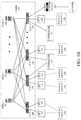
- FIGS. 1A and 1Billustrate example network environments
- FIG. 2Aillustrates an example object model for a network
- FIG. 2Billustrates an example object model for a tenant object in the example object model from FIG. 2A ;
- FIG. 2Cillustrates an example association of various objects in the example object model from FIG. 2A ;
- FIG. 2Dillustrates a schematic diagram of example models for implementing the example object model from FIG. 2A ;
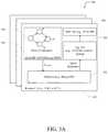
- FIG. 3Aillustrates an example network assurance appliance
- FIG. 3Billustrates an example system for network assurance
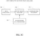
- FIG. 3Cillustrates a schematic diagram of an example system for static policy analysis in a network
- FIG. 4illustrates an example method embodiment for network assurance and fault code aggregation
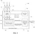
- FIG. 5illustrates an example architecture for of a formal analysis engine
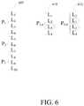
- FIG. 6illustrates an example rule set of priority-ordered rules falling into various priority classes
- FIG. 7illustrates an example network device in accordance with various embodiments.
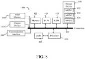
- FIG. 8illustrates an example computing device in accordance with various embodiments.
- references to “one embodiment” or “an embodiment”means that a particular feature, structure, or characteristic described in connection with the embodiment is included in at least one embodiment of the disclosure.
- the appearances of the phrase “in one embodiment” in various places in the specificationare not necessarily all referring to the same embodiment, nor are separate or alternative embodiments mutually exclusive of other embodiments.
- various featuresare described which may be exhibited by some embodiments and not by others.
- ROBDDsReduced Ordered Binary Decision Diagrams
- a logical model of network intentscan be a model generated based on configurations defined in one or more controllers or servers in a software-defined network (SDN), such as an APIC (application policy infrastructure controller) in an ACI (application-centric infrastructure) network.
- SDNsoftware-defined network
- APICapplication policy infrastructure controller
- ACIapplication-centric infrastructure
- the logical modelcan thus represent the logical configuration of the SDN network (e.g., a representation of the logical configurations in the ACI).
- the logical configuration of the SDN networkcan be based on the configurations defined by the network operator for the SDN network, such as the configurations entered into the APIC of an ACI network, and may thus reflect the intent of the network operator or the intended behavior of the SDN network.
- a hardware model of network intentscan be a model generated based on the logical model.
- the hardware modelcan thus represent the hardware rendering of the discrete software-defined components that comprise the logical model.
- the hardware rendering of the logical modelmight cause a single logical intent to be broken into multiple different hardware intents. This is not problematic in and of itself, as long as the multiple hardware intents capture the exact same effect as the single logical intent.
- conventional network assurance processesstruggle to make this determination of equivalency, as it requires a comparison of two models of network intents that do not have a congruent form. As such, it would be desirable to provide intelligent network assurance via systems and methods for identifying conflict rules between two or more models of network intents that are not necessarily congruent in form or in composition.
- the disclosed technologyaddresses the need in the art for a reliable and efficient ability to determine whether constituent rules of a single priority class of a given model of network intent are shadowed by other rules within the same priority class.
- the present technologywill be subsequently described as follows.
- the discussionbegins with an introductory discussion of network assurance and a description of example computing environments, as illustrated in FIGS. 1A and 1B .
- the discussioncontinues with a description of systems and methods for network assurance, network modeling, and event generation, as shown in FIGS. 2A-2D, 3A -C, and 4 .
- the discussionmoves next to an example formal analysis architecture as illustrated in FIG. 5 , and an example set of priority ordered rules of various priority classes, as seen in FIG. 6 .
- Network assuranceis the guarantee or determination that the network is behaving as intended by the network operator and has been configured properly (e.g., the network is doing what it is intended to do).
- Intentcan encompass various network operations, such as bridging, routing, security, service chaining, endpoints, compliance, QoS (Quality of Service), audits, etc.
- Intentcan be embodied in one or more policies, settings, configurations, etc., defined for the network and individual network elements (e.g., switches, routers, applications, resources, etc.). However, often times, the configurations, policies, etc., defined by a network operator are incorrect or not accurately reflected in the actual behavior of the network.
- a network operatorspecifies a configuration A for one or more types of traffic but later finds out that the network is actually applying configuration B to that traffic or otherwise processing that traffic in a manner that is inconsistent with configuration A.
- Thiscan be a result of many different causes, such as hardware errors, software bugs, varying priorities, configuration conflicts, misconfiguration of one or more settings, improper rule rendering by devices, unexpected errors or events, software upgrades, configuration changes, failures, etc.
- a network operatorimplements configuration C but one or more other configurations result in the network behaving in a manner that is inconsistent with the intent reflected by the implementation of configuration C. For example, such a situation can result when configuration C conflicts with other configurations in the network.
- the approaches hereincan provide network assurance by modeling various aspects of the network and/or performing consistency checks as well as other network assurance checks.
- the network assurance approaches hereincan be implemented in various types of networks, including a private network, such as a local area network (LAN); an enterprise network; a standalone or traditional network, such as a data center network; a network including a physical or underlay layer and a logical or overlay layer, such as a VXLAN or software-defined network (SDN) (e.g., Application Centric Infrastructure (ACI) or VMware NSX networks); etc.
- SDNsoftware-defined network
- the approaches hereincan also enable identification and visualization of hardware-level (e.g., network switch-level) errors along any software or application-centric dimension.
- Logical modelscan be implemented to represent various aspects of a network.
- a modelcan include a mathematical or semantic model of the network, including, without limitation the network's policies, configurations, requirements, security, routing, topology, applications, hardware, filters, contracts, access control lists, EPGs, application profiles, tenants, etc.
- Modelscan be implemented to provide network assurance to ensure that the network is properly configured and the behavior of the network will be consistent (or is consistent) with the intended behavior reflected through specific policies, settings, definitions, etc., implemented by the network operator.
- network assurancecan be performed through modeling without necessarily ingesting any packet data or monitoring traffic or network behavior. This can result in foresight, insight, and hindsight: problems can be prevented before they occur, identified when they occur, and fixed immediately after they occur.
- Properties of the networkcan be mathematically modeled to deterministically predict the behavior and condition of the network.
- a mathematical modelcan abstract the control, management, and data planes, and may use various techniques such as symbolic, formal verification, consistency, graph, behavioral, etc.
- the networkcan be determined to be healthy if the model(s) indicate proper behavior (e.g., no inconsistencies, conflicts, errors, etc.).
- the networkcan be determined to be functional, but not fully healthy, if the modeling indicates proper behavior but some inconsistencies.
- the networkcan be determined to be non-functional and not healthy if the modeling indicates improper behavior and errors. If inconsistencies or errors are detected by the modeling, a detailed analysis of the corresponding model(s) can allow one or more underlying or root problems to be identified with great accuracy.
- the modelscan consume numerous types of data and/or events which model a large amount of behavioral aspects of the network. Such data and events can impact various aspects of the network, such as underlay services, overlay service, tenant connectivity, tenant security, tenant EP mobility, tenant policy, resources, etc.
- FIG. 1Aillustrates a diagram of an example Network Environment 100 , such as a data center.
- the Network Environment 100can include a Fabric 120 which can represent the physical layer or infrastructure (e.g., underlay) of the Network Environment 100 .
- Fabric 120can include Spines 102 (e.g., spine routers or switches) and Leafs 104 (e.g., leaf routers or switches) which can be interconnected for routing or switching traffic in the Fabric 120 .
- Spines 102can interconnect Leafs 104 in the Fabric 120
- Leafs 104can connect the Fabric 120 to an overlay or logical portion of the Network Environment 100 , which can include application services, servers, virtual machines, containers, endpoints, etc.
- Network connectivity in the Fabric 120can flow from Spines 102 to Leafs 104 , and vice versa.
- the interconnections between Leafs 104 and Spines 102can be redundant (e.g., multiple interconnections) to avoid a failure in routing.
- Leafs 104 and Spines 102can be fully connected, such that any given Leaf is connected to each of the Spines 102 , and any given Spine is connected to each of the Leafs 104 .
- Leafs 104can be, for example, top-of-rack (“ToR”) switches, aggregation switches, gateways, ingress and/or egress switches, provider edge devices, and/or any other type of routing or switching device.
- ToRtop-of-rack
- Leafs 104can be responsible for routing and/or bridging tenant or customer packets and applying network policies or rules. Network policies and rules can be driven by one or more Controllers 116 , and/or implemented or enforced by one or more devices, such as Leafs 104 .
- Leafs 104can connect other elements to the Fabric 120 .
- Leafs 104can connect Servers 106 , Hypervisors 108 , Virtual Machines (VMs) 110 , Applications 112 , Network Device 114 , etc., with Fabric 120 .
- Such elementscan reside in one or more logical or virtual layers or networks, such as an overlay network.
- Leafs 104can encapsulate and decapsulate packets to and from such elements (e.g., Servers 106 ) in order to enable communications throughout Network Environment 100 and Fabric 120 .
- Leafs 104can also provide any other devices, services, tenants, or workloads with access to Fabric 120 .
- Servers 106 connected to Leafs 104can similarly encapsulate and decapsulate packets to and from Leafs 104 .
- Servers 106can include one or more virtual switches or routers or tunnel endpoints for tunneling packets between an overlay or logical layer hosted by, or connected to, Servers 106 and an underlay layer represented by Fabric 120 and accessed via Leafs 104 .
- Applications 112can include software applications, services, containers, appliances, functions, service chains, etc.
- Applications 112can include a firewall, a database, a CDN server, an IDS/IPS, a deep packet inspection service, a message router, a virtual switch, etc.
- An application from Applications 112can be distributed, chained, or hosted by multiple endpoints (e.g., Servers 106 , VMs 110 , etc.), or may run or execute entirely from a single endpoint.
- VMs 110can be virtual machines hosted by Hypervisors 108 or virtual machine managers running on Servers 106 .
- VMs 110can include workloads running on a guest operating system on a respective server.
- Hypervisors 108can provide a layer of software, firmware, and/or hardware that creates, manages, and/or runs the VMs 110 .
- Hypervisors 108can allow VMs 110 to share hardware resources on Servers 106 , and the hardware resources on Servers 106 to appear as multiple, separate hardware platforms.
- Hypervisors 108 on Servers 106can host one or more VMs 110 .
- VMs 110 and/or Hypervisors 108can be migrated to other Servers 106 .
- Servers 106can similarly be migrated to other locations in Network Environment 100 .
- a server connected to a specific leafcan be changed to connect to a different or additional leaf.
- Such configuration or deployment changescan involve modifications to settings, configurations and policies that are applied to the resources being migrated as well as other network components.
- one or more Servers 106 , Hypervisors 108 , and/or VMs 110can represent or reside in a tenant or customer space.
- Tenant spacecan include workloads, services, applications, devices, networks, and/or resources that are associated with one or more clients or subscribers. Accordingly, traffic in Network Environment 100 can be routed based on specific tenant policies, spaces, agreements, configurations, etc. Moreover, addressing can vary between one or more tenants. In some configurations, tenant spaces can be divided into logical segments and/or networks and separated from logical segments and/or networks associated with other tenants. Addressing, policy, security and configuration information between tenants can be managed by Controllers 116 , Servers 106 , Leafs 104 , etc.
- Configurations in Network Environment 100can be implemented at a logical level, a hardware level (e.g., physical), and/or both.
- configurationscan be implemented at a logical and/or hardware level based on endpoint or resource attributes, such as endpoint types and/or application groups or profiles, through a software-defined network (SDN) framework (e.g., Application-Centric Infrastructure (ACI) or VMWARE NSX).
- SDNsoftware-defined network
- ACIApplication-Centric Infrastructure
- VMWARE NSXsoftware-defined network
- one or more administratorscan define configurations at a logical level (e.g., application or software level) through Controllers 116 , which can implement or propagate such configurations through Network Environment 100 .
- Controllers 116can be Application Policy Infrastructure Controllers (APICs) in an ACI framework.
- Controllers 116can be one or more management components for associated with other SDN solutions, such as NSX Managers.
- Such configurationscan define rules, policies, priorities, protocols, attributes, objects, etc., for routing and/or classifying traffic in Network Environment 100 .
- such configurationscan define attributes and objects for classifying and processing traffic based on Endpoint Groups (EPGs), Security Groups (SGs), VM types, bridge domains (BDs), virtual routing and forwarding instances (VRFs), tenants, priorities, firewall rules, etc.
- EPGsEndpoint Groups
- SGsSecurity Groups
- VM typesVM types
- BDsbridge domains
- VRFsvirtual routing and forwarding instances
- tenantspriorities, firewall rules, etc.
- Traffic policies and rulescan be enforced based on tags, attributes, or other characteristics of the traffic, such as protocols associated with the traffic, EPGs associated with the traffic, SGs associated with the traffic, network address information associated with the traffic, etc.
- Network Environment 100can be configured according to one or more particular software-defined network (SDN) solutions, such as CISCO ACI or VMWARE NSX. These example SDN solutions are briefly described below.
- SDNsoftware-defined network
- ACIcan provide an application-centric or policy-based solution through scalable distributed enforcement.
- ACIsupports integration of physical and virtual environments under a declarative configuration model for networks, servers, services, security, requirements, etc.
- the ACI frameworkimplements EPGs, which can include a collection of endpoints or applications that share common configuration requirements, such as security, QoS, services, etc.
- Endpointscan be virtual/logical or physical devices, such as VMs, containers, hosts, or physical servers that are connected to Network Environment 100 .
- Endpointscan have one or more attributes such as a VM name, guest OS name, a security tag, application profile, etc.
- Application configurationscan be applied between EPGs, instead of endpoints directly, in the form of contracts.
- Leafs 104can classify incoming traffic into different EPGs.
- the classificationcan be based on, for example, a network segment identifier such as a VLAN ID, VXLAN Network Identifier (VNID), NVGRE Virtual Subnet Identifier (VSID), MAC address, IP address, etc.
- VNIDVXLAN Network Identifier
- VSIDVirtual Subnet Identifier
- MAC addressIP address
- IP addressIP address
- classification in the ACI infrastructurecan be implemented by Application Virtual Switches (AVS), which can run on a host, such as a server or switch.
- AVSApplication Virtual Switches
- an AVScan classify traffic based on specified attributes, and tag packets of different attribute EPGs with different identifiers, such as network segment identifiers (e.g., VLAN ID).
- Leafs 104can tie packets with their attribute EPGs based on their identifiers and enforce policies, which can be implemented and/or managed by one or more Controllers 116 .
- Leaf 104can classify to which EPG the traffic from a host belongs and enforce policies accordingly.
- VMWARE NSXhosts can run a distributed firewall (DFW) which can classify and process traffic.
- DFWdistributed firewall
- VMsnamely, application, database and web VMs
- Traffic protectioncan be provided within the network segment based on the VM type.
- HTTP trafficcan be permitted among web VMs, and not permitted between a web VM and an application or database VM.
- security groupscan be used to group the specific VMs (e.g., web VMs, application VMs, database VMs).
- DFW rulescan be configured to implement policies for the specific security groups.
- DFW rulescan be configured to block HTTP traffic between web, application, and database security groups.
- Network Environment 100can deploy different hosts via Leafs 104 , Servers 106 , Hypervisors 108 , VMs 110 , Applications 112 , and Controllers 116 , such as VMWARE ESXi hosts, WINDOWS HYPER-V hosts, bare metal physical hosts, etc.
- Network Environment 100may interoperate with a variety of Hypervisors 108 , Servers 106 (e.g., physical and/or virtual servers), SDN orchestration platforms, etc.
- Network Environment 100may implement a declarative model to allow its integration with application design and holistic network policy.
- Controllers 116can provide centralized access to fabric information, application configuration, resource configuration, application-level configuration modeling for a software-defined network (SDN) infrastructure, integration with management systems or servers, etc. Controllers 116 can form a control plane that interfaces with an application plane via northbound APIs and a data plane via southbound APIs.
- SDNsoftware-defined network
- Controllers 116can define and manage application-level model(s) for configurations in Network Environment 100 .
- application or device configurationscan also be managed and/or defined by other components in the network.
- a hypervisor or virtual appliancesuch as a VM or container, can run a server or management tool to manage software and services in Network Environment 100 , including configurations and settings for virtual appliances.
- Network Environment 100can include one or more different types of SDN solutions, hosts, etc.
- Controllers 116may be interchangeably referenced as controllers, APICs, or APIC controllers.
- the technologies and concepts hereinare not limited to ACI solutions and may be implemented in other architectures and scenarios, including other SDN solutions as well as other types of networks which may not deploy an SDN solution.
- hostscan refer to Servers 106 (e.g., physical or logical), Hypervisors 108 , VMs 110 , containers (e.g., Applications 112 ), etc., and can run or include any type of server or application solution.
- Non-limiting examples of “hosts”can include virtual switches or routers, such as distributed virtual switches (DVS), application virtual switches (AVS), vector packet processing (VPP) switches; VCENTER and NSX MANAGERS; bare metal physical hosts; HYPER-V hosts; VMs; DOCKER Containers; etc.
- FIG. 1Billustrates another example of Network Environment 100 .
- Network Environment 100includes Endpoints 122 connected to Leafs 104 in Fabric 120 .
- Endpoints 122can be physical and/or logical or virtual entities, such as servers, clients, VMs, hypervisors, software containers, applications, resources, network devices, workloads, etc.
- an Endpoint 122can be an object that represents a physical device (e.g., server, client, switch, etc.), an application (e.g., web application, database application, etc.), a logical or virtual resource (e.g., a virtual switch, a virtual service appliance, a virtualized network function (VNF), a VM, a service chain, etc.), a container running a software resource (e.g., an application, an appliance, a VNF, a service chain, etc.), storage, a workload or workload engine, etc.
- a physical devicee.g., server, client, switch, etc.
- an applicatione.g., web application, database application, etc.
- a logical or virtual resourcee.g., a virtual switch, a virtual service appliance, a virtualized network function (VNF), a VM, a service chain, etc.
- VNFvirtualized network function
- VMvirtualized network function
- a container running a software resourcee.g
- Endpoints 122can have an address (e.g., an identity), a location (e.g., host, network segment, virtual routing and forwarding (VRF) instance, domain, etc.), one or more attributes (e.g., name, type, version, patch level, OS name, OS type, etc.), a tag (e.g., security tag), a profile, etc.
- an addresse.g., an identity
- a locatione.g., host, network segment, virtual routing and forwarding (VRF) instance, domain, etc.
- attributese.g., name, type, version, patch level, OS name, OS type, etc.
- a tage.g., security tag
- Endpoints 122can be associated with respective Logical Groups 118 .
- Logical Groups 118can be logical entities containing endpoints (physical and/or logical or virtual) grouped together according to one or more attributes, such as endpoint type (e.g., VM type, workload type, application type, etc.), one or more requirements (e.g., policy requirements, security requirements, QoS requirements, customer requirements, resource requirements, etc.), a resource name (e.g., VM name, application name, etc.), a profile, platform or operating system (OS) characteristics (e.g., OS type or name including guest and/or host OS, etc.), an associated network or tenant, one or more policies, a tag, etc.
- endpoint typee.g., VM type, workload type, application type, etc.
- requirementse.g., policy requirements, security requirements, QoS requirements, customer requirements, resource requirements, etc.
- a resource namee.g., VM name, application name, etc.
- a logical groupcan be an object representing a collection of endpoints grouped together.
- Logical Group 1can contain client endpoints
- Logical Group 2can contain web server endpoints
- Logical Group 3can contain application server endpoints
- Logical Group Ncan contain database server endpoints, etc.
- Logical Groups 118are EPGs in an ACI environment and/or other logical groups (e.g., SGs) in another SDN environment.
- Logical Groups 118can be used to classify traffic to or from Endpoints 122 , apply policies to traffic to or from Endpoints 122 , define relationships between Endpoints 122 , define roles of Endpoints 122 (e.g., whether an endpoint consumes or provides a service, etc.), apply rules to traffic to or from Endpoints 122 , apply filters or access control lists (ACLs) to traffic to or from Endpoints 122 , define communication paths for traffic to or from Endpoints 122 , enforce requirements associated with Endpoints 122 , implement security and other configurations associated with Endpoints 122 , etc.
- ACLsaccess control lists
- Logical Groups 118can be EPGs used to define contracts in the ACI. Contracts can include rules specifying what and how communications between EPGs take place. For example, a contract can define what provides a service, what consumes a service, and what policy objects are related to that consumption relationship. A contract can include a policy that defines the communication path and all related elements of a communication or relationship between endpoints or EPGs. For example, a Web EPG can provide a service that a Client EPG consumes, and that consumption can be subject to a filter (ACL) and a service graph that includes one or more services, such as firewall inspection services and server load balancing.
- ACLfilter
- FIG. 2Aillustrates a diagram of an example Management Information Model 200 for an SDN network, such as Network Environment 100 .
- Management Information Model 200references various terms which shall also be used throughout the disclosure. Accordingly, for clarity, the disclosure shall first provide below a list of terminology, which will be followed by a more detailed discussion of Management Information Model 200 .
- the terms “Aliasing” and “Shadowing”can refer to a rule (e.g., contracts, policies, configurations, etc.) that overlaps one or more other rules.
- Contract 1 defined in a logical model of a networkcan be said to be aliasing or shadowing Contract 2 defined in the logical model of the network if Contract 1 overlaps Contract 2.
- Contract 1may render Contract 2 redundant or inoperable. For example, if Contract 1 has a higher priority than Contract 2, such aliasing can render Contract 2 redundant based on Contract 1's overlapping and higher priority characteristics.
- the term “APIC”can refer to one or more controllers (e.g., Controllers 116 ) in an ACI framework.
- the APICcan provide a unified point of automation and management, policy programming, application deployment, health monitoring for an ACI multitenant fabric.
- the APICcan be implemented as a single controller, a distributed controller, or a replicated, synchronized, and/or clustered controller.
- BDDcan refer to a binary decision tree.
- a binary decision treecan be a data structure representing functions, such as Boolean functions.
- BDcan refer to a bridge domain.
- a bridge domaincan be a set of logical ports that share the same flooding or broadcast characteristics. Like a virtual LAN (VLAN), bridge domains can span multiple devices.
- a bridge domaincan be a L2 (Layer 2) construct.
- a “Consumer”can refer to an endpoint, resource, and/or EPG that consumes a service.
- a “Context”can refer to an L3 (Layer 3) address domain that permits multiple instances of a routing table to exist and work simultaneously. This increases functionality by permitting network paths to be segmented without using multiple devices.
- Non-limiting examples of a context or L3 address domaincan include a Virtual Routing and Forwarding (VRF) instance, a private network, and so forth.
- VRFVirtual Routing and Forwarding
- Constantcan refer to rules or configurations that specify what and how communications in a network are conducted (e.g., permitted, denied, filtered, processed, etc.).
- contractscan specify how communications between endpoints and/or EPGs take place.
- a contractcan provide rules and configurations akin to an Access Control List (ACL).
- ACLAccess Control List
- DNcan refer to a unique name that describes an object, such as an MO, and locates its place in Management Information Model 200 .
- the DNcan be (or equate to) a Fully Qualified Domain Name (FQDN).
- FQDNFully Qualified Domain Name
- Endpoint Groupcan refer to a logical entity or object associated with a collection or group of endoints as previously described with reference to FIG. 1B .
- the term “Filter”can refer to a parameter or configuration for permitting communications. For example, in a whitelist model where all communications are blocked by default, a communication must be given explicit permission to prevent such communication from being blocked.
- a filtercan define permission(s) for one or more communications or packets. A filter can thus function similar to an ACL or Firewall rule.
- a filtercan be implemented in a packet (e.g., TCP/IP) header field, such as L3 protocol type, L4 (Layer 4) ports, and so on, which is used to permit inbound or outbound communications between endpoints or EPGs, for example.
- L2 Outcan refer to a bridged connection.
- a bridged connectioncan connect two or more segments of the same network so that they can communicate.
- an L2 outcan be a bridged (Layer 2) connection between an ACI fabric (e.g., Fabric 120 ) and an outside Layer 2 network, such as a switch.
- ACI fabrice.g., Fabric 120
- an outside Layer 2 networksuch as a switch.
- L3 Outcan refer to a routed connection.
- a routed Layer 3 connectionuses a set of protocols that determine the path that data follows in order to travel across networks from its source to its destination. Routed connections can perform forwarding (e.g., IP forwarding) according to a protocol selected, such as BGP (border gateway protocol), OSPF (Open Shortest Path First), EIGRP (Enhanced Interior Gateway Routing Protocol), etc.
- BGPborder gateway protocol
- OSPFOpen Shortest Path First
- EIGRPEnhanced Interior Gateway Routing Protocol
- MOManaged Object
- the MOscan be network resources or elements that are managed in the network.
- an MOcan include an abstraction of an ACI fabric (e.g., Fabric 120 ) resource.
- MITManagement Information Tree
- the MITcontains the MOs of the ACI fabric (e.g., Fabric 120 ).
- the MITcan also be referred to as a Management Information Model (MIM), such as Management Information Model 200 .
- MIMManagement Information Model
- Policycan refer to one or more specifications for controlling some aspect of system or network behavior.
- a policycan include a named entity that contains specifications for controlling some aspect of system behavior.
- a Layer 3 Outside Network Policycan contain the BGP protocol to enable BGP routing functions when connecting Fabric 120 to an outside Layer 3 network.
- Profilecan refer to the configuration details associated with a policy.
- a profilecan include a named entity that contains the configuration details for implementing one or more instances of a policy.
- a switch node profile for a routing policycan contain the switch-specific configuration details to implement the BGP routing protocol.
- a providerrefers to an object or entity providing a service.
- a providercan be an EPG that provides a service.
- Subjectrefers to one or more parameters in a contract for defining communications.
- subjects in a contractcan specify what information can be communicated and how.
- Subjectscan function similar to ACLs.
- a tenantrefers to a unit of isolation in a network.
- a tenantcan be a secure and exclusive virtual computing environment.
- a tenantcan be a unit of isolation from a policy perspective, but does not necessarily represent a private network.
- ACI tenantscan contain multiple private networks (e.g., VRFs).
- Tenantscan represent a customer in a service provider setting, an organization or domain in an enterprise setting, or just a grouping of policies.
- VRFrefers to a virtual routing and forwarding instance.
- the VRFcan define a Layer 3 address domain that permits multiple instances of a routing table to exist and work simultaneously. This increases functionality by permitting network paths to be segmented without using multiple devices. Also known as a context or private network.
- MIM 200can be a hierarchical management information tree or MIT.
- MIM 200can be managed and processed by Controllers 116 , such as APICs in an ACI. Controllers 116 can enable the control of managed resources by presenting their manageable characteristics as object properties that can be inherited according to the location of the object within the hierarchical structure of the model.
- the hierarchical structure of MIM 200starts with Policy Universe 202 at the top (Root) and contains parent and child nodes 116 , 204 , 206 , 208 , 210 , 212 .
- Nodes 116 , 202 , 204 , 206 , 208 , 210 , 212 in the treerepresent the managed objects (MOs) or groups of objects.
- Each object in the fabrice.g., Fabric 120
- DNunique distinguished name
- the Nodes 116 , 202 , 204 , 206 , 208 , 210 , 212can include the various MOs, as described below, which contain policies that govern the operation of the system.
- Controllers 116can provide management, policy programming, application deployment, and health monitoring for Fabric 120 .
- Node 204includes a tenant container for policies that enable an administrator to exercise domain-based access control.
- tenantscan include:
- User tenantsdefined by the administrator according to the needs of users. They contain policies that govern the operation of resources such as applications, databases, web servers, network-attached storage, virtual machines, and so on.
- the common tenantis provided by the system but can be configured by the administrator. It contains policies that govern the operation of resources accessible to all tenants, such as firewalls, load balancers, Layer 4 to Layer 7 services, intrusion detection appliances, and so on.
- the infrastructure tenantis provided by the system but can be configured by the administrator. It contains policies that govern the operation of infrastructure resources such as the fabric overlay (e.g., VXLAN). It also enables a fabric provider to selectively deploy resources to one or more user tenants. Infrastructure tenant polices can be configurable by the administrator.
- the management tenantis provided by the system but can be configured by the administrator. It contains policies that govern the operation of fabric management functions used for in-band and out-of-band configuration of fabric nodes.
- the management tenantcontains a private out-of-bound address space for the Controller/Fabric internal communications that is outside the fabric data path that provides access through the management port of the switches.
- the management tenantenables discovery and automation of communications with virtual machine controllers.
- Node 206can contain access policies that govern the operation of switch access ports that provide connectivity to resources such as storage, compute, Layer 2 and Layer 3 (bridged and routed) connectivity, virtual machine hypervisors, Layer 4 to Layer 7 devices, and so on. If a tenant requires interface configurations other than those provided in the default link, Cisco Discovery Protocol (CDP), Link Layer Discovery Protocol (LLDP), Link Aggregation Control Protocol (LACP), or Spanning Tree Protocol (STP), an administrator can configure access policies to enable such configurations on the access ports of Leafs 104 .
- CDPCisco Discovery Protocol
- LLDPLink Layer Discovery Protocol
- LACPLink Aggregation Control Protocol
- STPSpanning Tree Protocol
- Node 206can contain fabric policies that govern the operation of the switch fabric ports, including such functions as Network Time Protocol (NTP) server synchronization, Intermediate System-to-Intermediate System Protocol (IS-IS), Border Gateway Protocol (BGP) route reflectors, Domain Name System (DNS) and so on.
- the fabric MOcontains objects such as power supplies, fans, chassis, and so on.
- Node 208can contain VM domains that group VM controllers with similar networking policy requirements.
- VM controllerscan share virtual space (e.g., VLAN or VXLAN space) and application EPGs.
- Controllers 116communicate with the VM controller to publish network configurations such as port groups that are then applied to the virtual workloads.
- Node 210can contain Layer 4 to Layer 7 service integration life cycle automation framework that enables the system to dynamically respond when a service comes online or goes offline.
- Policiescan provide service device package and inventory management functions.
- Node 212can contain access, authentication, and accounting (AAA) policies that govern user privileges, roles, and security domains of Fabric 120 .
- AAAaccess, authentication, and accounting
- the hierarchical policy modelcan fit well with an API, such as a REST API interface.
- the APIWhen invoked, the API can read from or write to objects in the MIT. URLs can map directly into distinguished names that identify objects in the MIT. Data in the MIT can be described as a self-contained structured tree text document encoded in XML or JSON, for example.
- FIG. 2Billustrates an example object model 220 for a tenant portion of MIM 200 .
- a tenantis a logical container for application policies that enable an administrator to exercise domain-based access control.
- a tenantthus represents a unit of isolation from a policy perspective, but it does not necessarily represent a private network.
- Tenantscan represent a customer in a service provider setting, an organization or domain in an enterprise setting, or just a convenient grouping of policies.
- tenantscan be isolated from one another or can share resources.
- Tenant portion 204 A of MIM 200can include various entities, and the entities in Tenant Portion 204 A can inherit policies from parent entities.
- Non-limiting examples of entities in Tenant Portion 204 Acan include Filters 240 , Contracts 236 , Outside Networks 222 , Bridge Domains 230 , VRF Instances 234 , and Application Profiles 224 .
- Bridge Domains 230can include Subnets 232 .
- Contracts 236can include Subjects 238 .
- Application Profiles 224can contain one or more EPGs 226 . Some applications can contain multiple components. For example, an e-commerce application could require a web server, a database server, data located in a storage area network, and access to outside resources that enable financial transactions.
- Application Profile 224contains as many (or as few) EPGs as necessary that are logically related to providing the capabilities of an application.
- EPG 226can be organized in various ways, such as based on the application they provide, the function they provide (such as infrastructure), where they are in the structure of the data center (such as DMZ), or whatever organizing principle that a fabric or tenant administrator chooses to use.
- EPGs in the fabriccan contain various types of EPGs, such as application EPGs, Layer 2 external outside network instance EPGs, Layer 3 external outside network instance EPGs, management EPGs for out-of-band or in-band access, etc.
- EPGs 226can also contain Attributes 228 , such as encapsulation-based EPGs, IP-based EPGs, or MAC-based EPGs.
- EPGscan contain endpoints (e.g., EPs 122 ) that have common characteristics or attributes, such as common policy requirements (e.g., security, virtual machine mobility (VMM), QoS, or Layer 4 to Layer 7 services). Rather than configure and manage endpoints individually, they can be placed in an EPG and managed as a group.
- endpointse.g., EPs 122
- common characteristics or attributessuch as common policy requirements (e.g., security, virtual machine mobility (VMM), QoS, or Layer 4 to Layer 7 services).
- VMMvirtual machine mobility
- QoSvirtual machine mobility
- Layer 4 to Layer 7 servicesLayer 4 to Layer 7 services
- An EPGcan be statically configured by an administrator in Controllers 116 , or dynamically configured by an automated system such as VCENTER or OPENSTACK.
- fabric access policiesshould be configured and associated with tenant policies.
- Access policiesenable an administrator to configure other network configurations, such as port channels and virtual port channels, protocols such as LLDP, CDP, or LACP, and features such as monitoring or diagnostics.
- FIG. 2Cillustrates an example Association 260 of tenant entities and access entities in MIM 200 .
- Policy Universe 202contains Tenant Portion 204 A and Access Portion 206 A. Thus, Tenant Portion 204 A and Access Portion 206 A are associated through Policy Universe 202 .
- Access Portion 206 Acan contain fabric and infrastructure access policies.
- EPGsare coupled with VLANs.
- VLANsFor traffic to flow, an EPG is deployed on a leaf port with a VLAN in a physical, VMM, L2 out, L3 out, or Fiber Channel domain, for example.
- Access Portion 206 Athus contains Domain Profile 236 which can define a physical, VMM, L2 out, L3 out, or Fiber Channel domain, for example, to be associated to the EPGs.
- Domain Profile 236contains VLAN Instance Profile 238 (e.g., VLAN pool) and Attacheable Access Entity Profile (AEP) 240 , which are associated directly with application EPGs.
- the AEP 240deploys the associated application EPGs to the ports to which it is attached, and automates the task of assigning VLANs. While a large data center can have thousands of active VMs provisioned on hundreds of VLANs, Fabric 120 can automatically assign VLAN IDs from VLAN pools. This saves time compared with trunking down VLANs in a traditional data center.
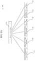
- FIG. 2Dillustrates a schematic diagram of example models for a network, such as Network Environment 100 .
- the modelscan be generated based on specific configurations and/or network state parameters associated with various objects, policies, properties, and elements defined in MIM 200 .
- the modelscan be implemented for network analysis and assurance, and may provide a depiction of the network at various stages of implementation and levels of the network.
- the modelscan include L_Model 270 A (Logical Model), LR_Model 270 B (Logical Rendered Model or Logical Runtime Model), Li_Model 272 (Logical Model for i), Ci_Model 274 (Concrete model for i), and/or Hi_Model 276 (Hardware model or TCAM Model for i).
- L_Model 270 Ais the logical representation of various elements in MIM 200 as configured in a network (e.g., Network Environment 100 ), such as objects, object properties, object relationships, and other elements in MIM 200 as configured in a network.
- L_Model 270 Acan be generated by Controllers 116 based on configurations entered in Controllers 116 for the network, and thus represents the logical configuration of the network at Controllers 116 . This is the declaration of the “end-state” expression that is desired when the elements of the network entities (e.g., applications, tenants, etc.) are connected and Fabric 120 is provisioned by Controllers 116 . Because L_Model 270 A represents the configurations entered in Controllers 116 , including the objects and relationships in MIM 200 , it can also reflect the “intent” of the administrator: how the administrator wants the network and network elements to behave.
- L_Model 270 Acan be a fabric or network-wide logical model.
- L_Model 270 Acan account configurations and objects from each of Controllers 116 .
- Network Environment 100can include multiple Controllers 116 .
- two or more Controllers 116may include different configurations or logical models for the network.
- L_Model 270 Acan obtain any of the configurations or logical models from Controllers 116 and generate a fabric or network wide logical model based on the configurations and logical models from all Controllers 116 .
- L_Model 270 Acan thus incorporate configurations or logical models between Controllers 116 to provide a comprehensive logical model.
- L_Model 270 Acan also address or account for any dependencies, redundancies, conflicts, etc., that may result from the configurations or logical models at the different Controllers 116 .
- LR_Model 270 Bis the abstract model expression that Controllers 116 (e.g., APICs in ACI) resolve from L_Model 270 A.
- LR_Model 270 Bcan provide the configuration components that would be delivered to the physical infrastructure (e.g., Fabric 120 ) to execute one or more policies.
- LR_Model 270 Bcan be delivered to Leafs 104 in Fabric 120 to configure Leafs 104 for communication with attached Endpoints 122 .
- LR_Model 270 Bcan also incorporate state information to capture a runtime state of the network (e.g., Fabric 120 ).
- LR_Model 270 Bcan provide a representation of L_Model 270 A that is normalized according to a specific format or expression that can be propagated to, and/or understood by, the physical infrastructure of Fabric 120 (e.g., Leafs 104 , Spines 102 , etc.). For example, LR_Model 270 B can associate the elements in L_Model 270 A with specific identifiers or tags that can be interpreted and/or compiled by the switches in Fabric 120 , such as hardware plane identifiers used as classifiers.
- Li_Model 272is a switch-level or switch-specific model obtained from L_Model 270 A and/or LR_Model 270 B. Li_Model 272 can project L_Model 270 A and/or LR_Model 270 B on a specific switch or device i, and thus can convey how L_Model 270 A and/or LR_Model 270 B should appear or be implemented at the specific switch or device i.
- Li_Model 272can project L_Model 270 A and/or LR_Model 270 B pertaining to a specific switch i to capture a switch-level representation of L_Model 270 A and/or LR_Model 270 B at switch i.
- Li_Model 272 L 1can represent L_Model 270 A and/or LR_Model 270 B projected to, or implemented at, Leaf 1 ( 104 ).
- Li_Model 272can be generated from L_Model 270 A and/or LR_Model 270 B for individual devices (e.g., Leafs 104 , Spines 102 , etc.) on Fabric 120 .
- Li_Model 272can be represented using JSON (JavaScript Object Notation).
- Li_Model 272can include JSON objects, such as Rules, Filters, Entries, and Scopes.
- Ci_Model 274is the actual in-state configuration at the individual fabric member i (e.g., switch i).
- Ci_Model 274is a switch-level or switch-specific model that is based on Li_Model 272 .
- Controllers 116can deliver Li_Model 272 to Leaf 1 ( 104 ).
- Leaf 1 ( 104 )can take Li_Model 272 , which can be specific to Leaf 1 ( 104 ), and render the policies in Li_Model 272 into a concrete model, Ci_Model 274 , that runs on Leaf 1 ( 104 ).
- Leaf 1 ( 104 )can render Li_Model 272 via the OS on Leaf 1 ( 104 ), for example.
- Ci_Model 274can be analogous to compiled software, as it is the form of Li_Model 272 that the switch OS at Leaf 1 ( 104 ) can execute.
- Li_Model 272 and Ci_Model 274can have a same or similar format.
- Li_Model 272 and Ci_Model 274can be based on JSON objects. Having the same or similar format can facilitate objects in Li_Model 272 and Ci_Model 274 to be compared for equivalence or congruence. Such equivalence or congruence checks can be used for network analysis and assurance, as further described herein.
- Hi_Model 276is also a switch-level or switch-specific model for switch i, but is based on Ci_Model 274 for switch i.
- Hi_Model 276is the actual configuration (e.g., rules) stored or rendered on the hardware or memory (e.g., TCAM memory) at the individual fabric member i (e.g., switch i).
- Hi_Model 276can represent the configurations (e.g., rules) which Leaf 1 ( 104 ) stores or renders on the hardware (e.g., TCAM memory) of Leaf 1 ( 104 ) based on Ci_Model 274 at Leaf 1 ( 104 ).
- the switch OS at Leaf 1 ( 104 )can render or execute Ci_Model 274 , and Leaf 1 ( 104 ) can store or render the configurations from Ci_Model 274 in storage, such as the memory or TCAM at Leaf 1 ( 104 ).
- the configurations from Hi_Model 276 stored or rendered by Leaf 1 ( 104 )represent the configurations that will be implemented by Leaf 1 ( 104 ) when processing traffic.
- Models 272 , 274 , 276are shown as device-specific models, similar models can be generated or aggregated for a collection of fabric members (e.g., Leafs 104 and/or Spines 102 ) in Fabric 120 .
- device-specific modelssuch as Model 272 , Model 274 , and/or Model 276
- Model 272 , Model 274 , and/or Model 276can provide a representation of Fabric 120 that extends beyond a particular device.
- Li_Model 272 , Ci_Model 274 , and/or Hi_Model 276 associated with some or all individual fabric members (e.g., Leafs 104 and Spines 102 )can be combined or aggregated to generate one or more aggregated models based on the individual fabric members.
- H Model, T Model, and TCAM Modelcan be used interchangeably to refer to a hardware model, such as Hi_Model 276 .
- Ti Model, Hi Model and TCAMi Modelmay be used interchangeably to refer to Hi_Model 276 .
- Models 270 A, 270 B, 272 , 274 , 276can provide representations of various aspects of the network or various configuration stages for MIM 200 .
- one or more of Models 270 A, 270 B, 272 , 274 , 276can be used to generate Underlay Model 278 representing one or more aspects of Fabric 120 (e.g., underlay topology, routing, etc.), Overlay Model 280 representing one or more aspects of the overlay or logical segment(s) of Network Environment 100 (e.g., COOP, MPBGP, tenants, VRFs, VLANs, VXLANs, virtual applications, VMs, hypervisors, virtual switching, etc.), Tenant Model 282 representing one or more aspects of Tenant portion 204 A in MIM 200 (e.g., security, forwarding, service chaining, QoS, VRFs, BDs, Contracts, Filters, EPGs, subnets, etc.), Resources Model 284 representing one or more resources in Network Environment 100 (e.g., storage
- L_Model 270 Acan be the high-level expression of what exists in the LR_Model 270 B, which should be present on the concrete devices as Ci_Model 274 and Hi_Model 276 expression. If there is any gap between the models, there may be inconsistent configurations or problems.
- FIG. 3Aillustrates a diagram of an example Assurance Appliance 300 for network assurance.
- Assurance Appliance 300can include k VMs 110 operating in cluster mode. VMs are used in this example for explanation purposes. However, it should be understood that other configurations are also contemplated herein, such as use of containers, bare metal devices, Endpoints 122 , or any other physical or logical systems.
- FIG. 3Aillustrates a cluster mode configuration, other configurations are also contemplated herein, such as a single mode configuration (e.g., single VM, container, or server) or a service chain for example.
- a single mode configuratione.g., single VM, container, or server
- service chainfor example.
- Assurance Appliance 300can run on one or more Servers 106 , VMs 110 , Hypervisors 108 , EPs 122 , Leafs 104 , Controllers 116 , or any other system or resource.
- Assurance Appliance 300can be a logical service or application running on one or more VMs 110 in Network Environment 100 .
- the Assurance Appliance 300can include Data Framework 308 , which can be based on, for example, APACHE APEX and HADOOP. In some cases, assurance checks can be written as individual operators that reside in Data Framework 308 . This enables a natively horizontal scale-out architecture that can scale to arbitrary number of switches in Fabric 120 (e.g., ACI fabric).
- Data Framework 308can be based on, for example, APACHE APEX and HADOOP. In some cases, assurance checks can be written as individual operators that reside in Data Framework 308 . This enables a natively horizontal scale-out architecture that can scale to arbitrary number of switches in Fabric 120 (e.g., ACI fabric).
- Assurance Appliance 300can poll Fabric 120 at a configurable periodicity (e.g., an epoch).
- the analysis workflowcan be setup as a DAG (Directed Acyclic Graph) of Operators 310 , where data flows from one operator to another and eventually results are generated and persisted to Database 302 for each interval (e.g., each epoch).
- DAGDirected Acyclic Graph
- the north-tierimplements API Server (e.g., APACHE Tomcat and Spring framework) 304 and Web Server 306 .
- API Servere.g., APACHE Tomcat and Spring framework
- Web Servere.g., Web Server
- GUIgraphical user interface
- Operators 310 in Data Framework 308can together support assurance operations.
- assurance operationscan be performed by Assurance Appliance 300 via Operators 310 .
- Assurance Appliance 300can check to make sure the configurations or specification from L_Model 270 A, which may reflect the user's intent for the network, including for example the security policies and customer-configured contracts, are correctly implemented and/or rendered in Li_Model 272 , Ci_Model 274 , and Hi_Model 276 , and thus properly implemented and rendered by the fabric members (e.g., Leafs 104 ), and report any errors, contract violations, or irregularities found.
- L_Model 270 Awhich may reflect the user's intent for the network, including for example the security policies and customer-configured contracts, are correctly implemented and/or rendered in Li_Model 272 , Ci_Model 274 , and Hi_Model 276 , and thus properly implemented and rendered by the fabric members (e.g., Leafs 104 ), and report any errors, contract violations, or irregularities found.
- Assurance Appliance 300can check for issues in the specification of the user's intent or intents (e.g., identify contradictory or conflicting policies in L_Model 270 A).
- TCAMis a scarce resource in the fabric (e.g., Fabric 120 ).
- Assurance Appliance 300can analyze the TCAM utilization by the network data (e.g., Longest Prefix Match (LPM) tables, routing tables, VLAN tables, BGP updates, etc.), Contracts, Logical Groups 118 (e.g., EPGs), Tenants, Spines 102 , Leafs 104 , and other dimensions in Network Environment 100 and/or objects in MIM 200 , to provide a network operator or user visibility into the utilization of this scarce resource. This can greatly help for planning and other optimization purposes.
- LPMLongest Prefix Match
- Assurance Appliance 300can validate that the fabric (e.g. fabric 120 ) has no inconsistencies in the Endpoint information registered (e.g., two leafs announcing the same endpoint, duplicate subnets, etc.), among other such checks.
- the fabrice.g. fabric 120
- the Endpoint informatione.g., two leafs announcing the same endpoint, duplicate subnets, etc.
- Assurance Appliance 300can validate that BDs, VRFs, subnets (both internal and external), VLANs, contracts, filters, applications, EPGs, etc., are correctly programmed.
- Assurance Appliance 300can validate that infrastructure routing (e.g., IS-IS protocol) has no convergence issues leading to black holes, loops, flaps, and other problems.
- infrastructure routinge.g., IS-IS protocol
- the network fabrice.g., Fabric 120
- the network fabriccan interface with other external networks and provide connectivity to them via one or more protocols, such as Border Gateway Protocol (BGP), Open Shortest Path First (OSPF), etc.
- BGPBorder Gateway Protocol
- OSPFOpen Shortest Path First
- the learned routesare advertised within the network fabric via, for example, MP-BGP.
- MP-BGPe.g., from Border Leaf
- Assurance Appliance 300can validate rules in the specification of the network (e.g., L_Model 270 A) are complete and do not have inconsistencies or other problems. MOs in the MIM 200 can be checked by Assurance Appliance 300 through syntactic and semantic checks performed on L_Model 270 A and/or the associated configurations of the MOs in MIM 200 . Assurance Appliance 300 can also verify that unnecessary, stale, unused or redundant configurations, such as contracts, are removed.
- rules in the specification of the networke.g., L_Model 270 A
- MOs in the MIM 200can be checked by Assurance Appliance 300 through syntactic and semantic checks performed on L_Model 270 A and/or the associated configurations of the MOs in MIM 200 .
- Assurance Appliance 300can also verify that unnecessary, stale, unused or redundant configurations, such as contracts, are removed.
- FIG. 3Billustrates an architectural diagram of an example system 350 for network assurance, such as Assurance Appliance 300 .
- system 350can correspond to the DAG of Operators 310 previously discussed with respect to FIG. 3A
- Topology Explorer 312communicates with Controllers 116 (e.g., APIC controllers) in order to discover or otherwise construct a comprehensive topological view of Fabric 120 (e.g., Spines 102 , Leafs 104 , Controllers 116 , Endpoints 122 , and any other components as well as their interconnections). While various architectural components are represented in a singular, boxed fashion, it is understood that a given architectural component, such as Topology Explorer 312 , can correspond to one or more individual Operators 310 and may include one or more nodes or endpoints, such as one or more servers, VMs, containers, applications, service functions (e.g., functions in a service chain or virtualized network function), etc.
- Controllers 116e.g., APIC controllers
- Topology Explorer 312is configured to discover nodes in Fabric 120 , such as Controllers 116 , Leafs 104 , Spines 102 , etc. Topology Explorer 312 can additionally detect a majority election performed amongst Controllers 116 , and determine whether a quorum exists amongst Controllers 116 . If no quorum or majority exists, Topology Explorer 312 can trigger an event and alert a user that a configuration or other error exists amongst Controllers 116 that is preventing a quorum or majority from being reached. Topology Explorer 312 can detect Leafs 104 and Spines 102 that are part of Fabric 120 and publish their corresponding out-of-band management network addresses (e.g., IP addresses) to downstream services. This can be part of the topological view that is published to the downstream services at the conclusion of Topology Explorer's 312 discovery epoch (e.g., 5 minutes, or some other specified interval).
- IP addressesout-of-band management network addresses
- Topology Explorer 312can receive as input a list of Controllers 116 (e.g., APIC controllers) that are associated with the network/fabric (e.g., Fabric 120 ). Topology Explorer 312 can also receive corresponding credentials to login to each controller. Topology Explorer 312 can retrieve information from each controller using, for example, REST calls. Topology Explorer 312 can obtain from each controller a list of nodes (e.g., Leafs 104 and Spines 102 ), and their associated properties, that the controller is aware of.
- Controllers 116e.g., APIC controllers
- Topology Explorer 312can also receive corresponding credentials to login to each controller. Topology Explorer 312 can retrieve information from each controller using, for example, REST calls. Topology Explorer 312 can obtain from each controller a list of nodes (e.g., Leafs 104 and Spines 102 ), and their associated properties, that the controller is aware of.
- Controllers 116e.g., APIC controllers
- Topology Explorer 312
- Topology Explorer 312can obtain node information from Controllers 116 including, without limitation, an IP address, a node identifier, a node name, a node domain, a node URI, a node_dm, a node role, a node version, etc.
- Topology Explorer 312can also determine if Controllers 116 are in quorum, or are sufficiently communicatively coupled amongst themselves. For example, if there are n controllers, a quorum condition might be met when (n/2+1) controllers are aware of each other and/or are communicatively coupled. Topology Explorer 312 can make the determination of a quorum (or identify any failed nodes or controllers) by parsing the data returned from the controllers, and identifying communicative couplings between their constituent nodes. Topology Explorer 312 can identify the type of each node in the network, e.g. spine, leaf, APIC, etc., and include this information in the topology information generated (e.g., topology map or model).
- topology information generatede.g., topology map or model
- Topology Explorer 312can trigger an event and alert a user that reconfiguration or suitable attention is required. If a quorum is present, Topology Explorer 312 can compile the network topology information into a JSON object and pass it downstream to other operators or services, such as Unified Collector 314 .
- Unified Collector 314can receive the topological view or model from Topology Explorer 312 and use the topology information to collect information for network assurance from Fabric 120 .
- Unified Collector 314can poll nodes (e.g., Controllers 116 , Leafs 104 , Spines 102 , etc.) in Fabric 120 to collect information from the nodes.
- nodese.g., Controllers 116 , Leafs 104 , Spines 102 , etc.
- Unified Collector 314can include one or more collectors (e.g., collector devices, operators, applications, VMs, etc.) configured to collect information from Topology Explorer 312 and/or nodes in Fabric 120 .
- Unified Collector 314can include a cluster of collectors, and each of the collectors can be assigned to a subset of nodes within the topological model and/or Fabric 120 in order to collect information from their assigned subset of nodes.
- Unified Collector 314can run in a parallel, multi-threaded fashion.
- Unified Collector 314can perform load balancing across individual collectors in order to streamline the efficiency of the overall collection process. Load balancing can be optimized by managing the distribution of subsets of nodes to collectors, for example by randomly hashing nodes to collectors.
- Assurance Appliance 300can run multiple instances of Unified Collector 314 . This can also allow Assurance Appliance 300 to distribute the task of collecting data for each node in the topology (e.g., Fabric 120 including Spines 102 , Leafs 104 , Controllers 116 , etc.) via sharding and/or load balancing, and map collection tasks and/or nodes to a particular instance of Unified Collector 314 with data collection across nodes being performed in parallel by various instances of Unified Collector 314 . Within a given node, commands and data collection can be executed serially. Assurance Appliance 300 can control the number of threads used by each instance of Unified Collector 314 to poll data from Fabric 120 .
- Unified Collector 314e.g., Assurance Appliance 300 to distribute the task of collecting data for each node in the topology (e.g., Fabric 120 including Spines 102 , Leafs 104 , Controllers 116 , etc.) via sharding and/or load balancing, and map collection tasks and/or no
- Unified Collector 314can collect models (e.g., L_Model 270 A and/or LR_Model 270 B) from Controllers 116 , switch software configurations and models (e.g., Ci_Model 274 ) from nodes (e.g., Leafs 104 and/or Spines 102 ) in Fabric 120 , hardware configurations and models (e.g., Hi_Model 276 ) from nodes (e.g., Leafs 104 and/or Spines 102 ) in Fabric 120 , etc.
- modelse.g., L_Model 270 A and/or LR_Model 270 B
- switch software configurations and modelse.g., Ci_Model 274
- nodese.g., Leafs 104 and/or Spines 102
- hardware configurations and modelse.g., Hi_Model 276
- Unified Collector 314can collect Ci_Model 274 and Hi_Model 276 from individual nodes or fabric members, such as Leafs 104 and Spines 102 , and L_Model 270 A and/or LR_Model 270 B from one or more controllers (e.g., Controllers 116 ) in Network Environment 100 .
- Controllers 116e.g., Controllers 116
- Unified Collector 314can poll the devices that Topology Explorer 312 discovers in order to collect data from Fabric 120 (e.g., from the constituent members of the fabric). Unified Collector 314 can collect the data using interfaces exposed by Controllers 116 and/or switch software (e.g., switch OS), including, for example, a Representation State Transfer (REST) Interface and a Secure Shell (SSH) Interface.
- switch OSe.g., switch OS
- Unified Collector 314collects L_Model 270 A, LR_Model 270 B, and/or Ci_Model 274 via a REST API, and the hardware information (e.g., configurations, tables, fabric card information, rules, routes, etc.) via SSH using utilities provided by the switch software, such as virtual shell (VSH or VSHELL) for accessing the switch command-line interface (CLI) or VSH_LC shell for accessing runtime state of the line card.
- VSHvirtual shell
- VSHELLvirtual shell
- CLIswitch command-line interface
- VSH_LC shellruntime state of the line card.
- Unified Collector 314can poll other information from Controllers 116 , including, without limitation: topology information, tenant forwarding/routing information, tenant security policies, contracts, interface policies, physical domain or VMM domain information, OOB (out-of-band) management IP's of nodes in the fabric, etc.
- Unified Collector 314can also poll information from nodes (e.g., Leafs 104 and Spines 102 ) in Fabric 120 , including without limitation: Ci_Models 274 for VLANs, BDs, and security policies; Link Layer Discovery Protocol (LLDP) connectivity information of nodes (e.g., Leafs 104 and/or Spines 102 ); endpoint information from EPM/COOP; fabric card information from Spines 102 ; routing information base (RIB) tables from nodes in Fabric 120 ; forwarding information base (FIB) tables from nodes in Fabric 120 ; security group hardware tables (e.g., TCAM tables) from nodes in Fabric 120 ; etc.
- LLDPLink Layer Discovery Protocol
- Unified Collector 314can obtain runtime state from the network and incorporate runtime state information into L_Model 270 A and/or LR_Model 270 B. Unified Collector 314 can also obtain multiple logical models from Controllers 116 and generate a comprehensive or network-wide logical model (e.g., L_Model 270 A and/or LR_Model 270 B) based on the logical models. Unified Collector 314 can compare logical models from Controllers 116 , resolve dependencies, remove redundancies, etc., and generate a single L_Model 270 A and/or LR_Model 270 B for the entire network or fabric.
- a comprehensive or network-wide logical modele.g., L_Model 270 A and/or LR_Model 270 B
- Unified Collector 314can collect the entire network state across Controllers 116 and fabric nodes or members (e.g., Leafs 104 and/or Spines 102 ). For example, Unified Collector 314 can use a REST interface and an SSH interface to collect the network state. This information collected by Unified Collector 314 can include data relating to the link layer, VLANs, BDs, VRFs, security policies, etc. The state information can be represented in LR_Model 270 B, as previously mentioned. Unified Collector 314 can then publish the collected information and models to any downstream operators that are interested in or require such information. Unified Collector 314 can publish information as it is received, such that data is streamed to the downstream operators.
- Unified Collector 314can publish information as it is received, such that data is streamed to the downstream operators.
- Unified Collector 314Data collected by Unified Collector 314 can be compressed and sent to downstream services.
- Unified Collector 314can collect data in an online fashion or real-time fashion, and send the data downstream, as it is collected, for further analysis.
- Unified Collector 314can collect data in an offline fashion, and compile the data for later analysis or transmission.
- Assurance Appliance 300can contact Controllers 116 , Spines 102 , Leafs 104 , and other nodes to collect various types of data. In some scenarios, Assurance Appliance 300 may experience a failure (e.g., connectivity problem, hardware or software error, etc.) that prevents it from being able to collect data for a period of time. Assurance Appliance 300 can handle such failures seamlessly, and generate events based on such failures.
- a failuree.g., connectivity problem, hardware or software error, etc.
- Switch Logical Policy Generator 316can receive L_Model 270 A and/or LR_Model 270 B from Unified Collector 314 and calculate Li_Model 272 for each network device i (e.g., switch i) in Fabric 120 .
- Switch Logical Policy Generator 316can receive L_Model 270 A and/or LR_Model 270 B and generate Li_Model 272 by projecting a logical model for each individual node i (e.g., Spines 102 and/or Leafs 104 ) in Fabric 120 .
- Switch Logical Policy Generator 316can generate Li_Model 272 for each switch in Fabric 120 , thus creating a switch logical model based on L_Model 270 A and/or LR_Model 270 B for each switch.
- Each Li_Model 272can represent L_Model 270 A and/or LR_Model 270 B as projected or applied at the respective network device i (e.g., switch i) in Fabric 120 .
- Li_Model 272can be normalized or formatted in a manner that is compatible with the respective network device.
- Li_Model 272can be formatted in a manner that can be read or executed by the respective network device.
- Li_Model 272can included specific identifiers (e.g., hardware plane identifiers used by Controllers 116 as classifiers, etc.) or tags (e.g., policy group tags) that can be interpreted by the respective network device.
- Li_Model 272can include JSON objects.
- Li_Model 272can include JSON objects to represent rules, filters, entries, scopes, etc.
- the format used for Li_Model 272can be the same as, or consistent with, the format of Ci_Model 274 .
- both Li_Model 272 and Ci_Model 274may be based on JSON objects.
- Similar or matching formatscan enable Li_Model 272 and Ci_Model 274 to be compared for equivalence or congruence. Such equivalency checks can aid in network analysis and assurance as further explained herein.
- Switch Logical Policy Generator 316can also perform change analysis and generate lint events or records for problems discovered in L_Model 270 A and/or LR_Model 270 B. The lint events or records can be used to generate alerts for a user or network operator via an event generator coupled to receive lint events from Switch Logical Policy Generator 316 .
- Policy Operator 318can receive Ci_Model 274 and Hi_Model 276 for each switch from Unified Collector 314 , and Li_Model 272 for each switch from Switch Logical Policy Generator 316 , and perform assurance checks and analysis (e.g., security adherence checks, TCAM utilization analysis, etc.) based on Ci_Model 274 , Hi_Model 276 , and Li_Model 272 . Policy Operator 318 can perform assurance checks on a switch-by-switch basis by comparing one or more of the models. The output of Policy Operator 318 can be passed to an event generator (not shown) that can generate warning events for external consumption, where the events correspond to security violations or utilization statistics (such as TCAM usage) that comprise a policy violation. Such events are triggered by an abnormal or undesirable network occurrence as determined by the network generator, whereas a notification event might be triggered during the normal course of performing utilization analysis and security adherence checks in the absence of any violations.
- assurance checks and analysise.g., security adherence checks, TCAM utilization analysis, etc.
- Unified Collector 314can also send L_Model 270 A and/or LR_Model 270 B to Routing Policy Parser 320 (for L models), and Ci_Model 274 and Hi_Model 276 to Routing Parser 326 (for C and H models).
- Routing Policy Parser 320can receive L_Model 270 A and/or LR_Model 270 B and parse the model(s) for information that may be relevant to downstream operators, such as Endpoint Checker 322 and Tenant Routing Checker 324 .
- Routing Parser 326can receive Ci_Model 274 and Hi_Model 276 and parse each model for information for downstream operators, Endpoint Checker 322 and Tenant Routing Checker 324 .
- Routing Policy Parser 320 and/or Routing Parser 326can send cleaned-up protocol buffers (Proto Buffs) to the downstream operators Endpoint Checker 322 and Tenant Routing Checker 324 .
- Endpoint Checker 322can communicate information related to Endpoint violations, such as duplicate IPs, APIPA, etc. to an event generator capable of generating events for external consumption or monitoring.
- Tenant Routing Checker 324can communicate information related to the deployment of BDs, VRFs, subnets, routing table prefixes, etc. to the same or different event generator capable of generating events for external consumption or monitoring.
- FIG. 3Cillustrates a schematic diagram of an example system for static policy analysis in a network (e.g., Network Environment 100 ).
- Static Policy Analyzer 360can perform assurance checks to detect configuration violations, logical lint events, contradictory or conflicting policies, unused contracts, incomplete configurations, etc.
- Static Policy Analyzer 360can check the specification of the user's intent or intents in L_Model 270 A to determine if any configurations in Controllers 116 are inconsistent with the specification of the user's intent or intents.
- Static Policy Analyzer 360can include one or more of the Operators 310 executed or hosted in Assurance Appliance 300 . However, in other configurations, Static Policy Analyzer 360 can run one or more operators or engines that are separate from Operators 310 and/or Assurance Appliance 300 .
- Static Policy Analyzer 360can be a VM, a cluster of VMs, or a collection of endpoints in a service function chain.
- Static Policy Analyzer 360can receive as input L_Model 270 A from Logical Model Collection Process 366 and Rules 368 defined for each feature (e.g., object) in L_Model 270 A.
- Rules 368can be based on objects, relationships, definitions, configurations, and any other features in MIM 200 .
- Rules 368can specify conditions, relationships, parameters, and/or any other information for identifying configuration violations or issues.
- Rules 368can include information for identifying syntactic violations or issues.
- Rules 368can include one or more rules for performing syntactic checks. Syntactic checks can verify that the configuration of L_Model 270 A is complete, and can help identify configurations or rules that are not being used. Syntactic checks can also verify that the configurations in the hierarchical MIM 200 are complete (have been defined) and identify any configurations that are defined but not used.
- Rules 368can specify that every tenant in L_Model 270 A should have a context configured; every contract in L_Model 270 A should specify a provider EPG and a consumer EPG; every contract in L_Model 270 A should specify a subject, filter, and/or port; etc.
- Rules 368can also include rules for performing semantic checks and identifying semantic violations or issues. Semantic checks can check conflicting rules or configurations. For example, Rule1 and Rule2 can have shadowing issues, Rule1 can be more specific than Rule2 and thereby create conflicts/issues, etc. Rules 368 can define conditions which may result in shadowed rules, conflicting rules, etc. To illustrate, Rules 368 can specify that a permit policy for a specific communication between two objects can conflict with a deny policy for the same communication between two objects if the permit policy has a higher priority than the deny policy, or a rule for an object renders another rule unnecessary.
- Static Policy Analyzer 360can apply Rules 368 to L_Model 270 A to check configurations in L_Model 270 A and output Configuration Violation Events 370 (e.g., alerts, logs, notifications, etc.) based on any issues detected.
- Configuration Violation Events 370can include semantic or semantic problems, such as incomplete configurations, conflicting configurations, aliased/shadowed rules, unused configurations, errors, policy violations, misconfigured objects, incomplete configurations, incorrect contract scopes, improper object relationships, etc.
- Static Policy Analyzer 360can iteratively traverse each node in a tree generated based on L_Model 270 A and/or MIM 200 , and apply Rules 368 at each node in the tree to determine if any nodes yield a violation (e.g., incomplete configuration, improper configuration, unused configuration, etc.). Static Policy Analyzer 360 can output Configuration Violation Events 370 when it detects any violations.
- a violatione.g., incomplete configuration, improper configuration, unused configuration, etc.
- FIG. 4illustrates an example flowchart for a network assurance model.
- the methodinvolves data collection.
- Data collectioncan include collection of data for operator intent, such as fabric data (e.g., topology, switch, interface policies, application policies, endpoint groups, etc.), network policies (e.g., BDs, VRFs, L2Outs, L3Outs, protocol configurations, etc.), security policies (e.g., contracts, filters, etc.), service chaining policies, and so forth.
- fabric datae.g., topology, switch, interface policies, application policies, endpoint groups, etc.
- network policiese.g., BDs, VRFs, L2Outs, L3Outs, protocol configurations, etc.
- security policiese.g., contracts, filters, etc.
- service chaining policiese.g., contracts, filters, etc.
- Data collectioncan also include data for the concrete, hardware model, such as network configuration (e.g., RIB/FIB, VLAN, MAC, ISIS, DB, BGP, OSPF, ARP, VPC, LLDP, MTU, QoS, etc.), security policies (e.g., TCAM, ECMP tables, etc.), endpoint dynamics (e.g., EPM, COOP EP DB, etc.), statistics (e.g., TCAM rule hits, interface counters, bandwidth, etc.).
- network configuratione.g., RIB/FIB, VLAN, MAC, ISIS, DB, BGP, OSPF, ARP, VPC, LLDP, MTU, QoS, etc.
- security policiese.g., TCAM, ECMP tables, etc.
- endpoint dynamicse.g., EPM, COOP EP DB, etc.
- statisticse.g., TCAM rule hits, interface counters, bandwidth, etc.
- the methodcan involve formal modeling and analysis.
- Formal modeling and analysiscan involve determining equivalency between logical and hardware models, such as security policies between models, etc.
- the methodcan involve smart event generation.
- Smart eventscan be generated using deep object hierarchy for detailed analysis, such as: Tenant, Leaf, VRFs, Rules; Filters, Routes, Prefixes, Port Numbers.
- the methodcan involve visualization.
- Formal modelscan be used to identify problems for analysis and debugging, in a user-friendly GUI.
- Each of the previously described modelsis, in one way or another, derived from the initial L-model that is configured by a user or network operator at the APIC or network controllers.
- the Li modelis a logical projection of the fabric-wide L model onto each leaf, spine, switch, node, etc. i in the network fabric
- the Ci modelis a concrete rendering of the L-model into a format that is compatible with the aforementioned fabric elements
- the Hi modelis the hardware representation of the Ci model, as stored into switch memory by a switch memory controller.
- each transformation used to derive the Li, Ci, and Hi modelspresents an opportunity for error or misconfiguration, which is undesirable from a network operator's point of view.
- errorscan result due to software bugs, user error, hardware variance, memory errors, overflow issues, and other causes that would be appreciated by one of ordinary skill in the art.
- each modelmay consist of thousands, or tens of thousands, of distinct rules that collectively represent the intents configured in the original L-model, and each of these distinct rules must be preserved when converting between the different models.
- FIG. 5depicts an example architecture 500 for a formal analysis system utilizing a shim layer 512 to extract and normalize underlying rules from input models of network intents 506 .
- Shim layer 512receives one or more input models of network intents 506 , depicted here as logical model Li, hardware model Hi, and concrete model Ci, although it is understood that a different number of models or different types of models could also be received without departing from the scope of the present disclosure. Additionally, it is understood that the following description is applicable to each switch, node, leaf, or spine element i that is contained within the network fabric of interest, although for purposes of clarity, reference is made herein to the Li, Hi, and Ci models that are derived from the same element i.
- the shim layer 512is designed to normalize the received models 506 and transform them into a consistent format for processing by the formal analysis engine 502 .
- the different received models 506are stored in different or otherwise inconsistent formats that would complicate the analysis of formal analysis engine 502 .
- the input models Li and Cimight be in a hierarchical format, such as a Managed Information Tree (MIT), while the input model Hi might be a non-hierarchical list extracted directly from a switches TCAM or memory entries.
- MITManaged Information Tree
- the most noticeable difference between the various input modelsis their usage of a hierarchical or non-hierarchical format.
- shim layer 512outputs a flattened list
- an input model 506 that is received in a hierarchical formate.g. Li or Ci
- a hierarchical formate.g. Li or Ci
- shim layer 512normalizes each flattened listing into a pre-determined format that represents the network intents encoded within each given input model 506 .
- flattened listings 507are output from shim layer 512 .
- the input model Liwill be output as the priority ordered flat list ⁇ tilde over (L) ⁇ l
- the input model Hiwill be output as the priority ordered flat list ⁇ tilde over (H) ⁇ l
- the input model Ciwill be output as the priority ordered flat list ⁇ tilde over (C) ⁇ l .
- each ruleconsists of an action (e.g. Permit, Permit_Log, Deny, Deny_Log) and a set of conditions that will trigger that action (e.g. packet source, destination, port, header, etc.).
- an actione.g. Permit, Permit_Log, Deny, Deny_Log
- a set of conditionse.g. packet source, destination, port, header, etc.
- a simple rulemight be designed to Permit all traffic on port 80 .
- Each rulecan be a 147 bit string, with 13 fields of key-value pairs.
- a priority ordered flat list of rulescan be encoded in one or more Reduced Ordered Binary Decision Diagrams (ROBDDs).
- ROBDDsReduced Ordered Binary Decision Diagrams
- a single ROBDDmight be used to encode the constituent rules of a model of network intents, or multiple ROBDDs might be used, e.g. one ROBDD for each action contained in the model of network intents. For example, this might result in a Permit ROBDD, Permit_Log ROBDD, Deny ROBDD, and a Deny_Log ROBDD.
- ROBDD Generator 530generates one or more ROBDDs that are canonical to the input flat listings of rules 507 , such that one or more ROBDDs encode the unique and non-unique contribution of each priority-ordered rule from the flat listing.
- ROBDD Generator 530receives as input ⁇ tilde over (L) ⁇ l ⁇ tilde over (H) ⁇ l and ⁇ tilde over (C) ⁇ l and generates as output the corresponding ROBDDs L BDD , H BDD , C BDD .
- a given ROBDDsuch as L BDD might actually consist of multiple action-specific ROBDDs such as L_Permit BDD L_Permit_Log BDD L_Deny BDD and L_Deny_Log BDD .
- rulescan be represented in their full (i.e. original) form, represented in a priority reduced form, or both.
- the full formis simply the form in which the rules were originally entered or created, and includes any overlaps or redundancies between separate rules.
- a priority reduced formremoves the redundancies and overlaps, based on a given priority or hierarchical ordering of the rules. In this sense, a given rule has only a single full form, but can have numerous different priority reduced forms, depending on the priority listing that was used for the overall set of rules to which the given rule belongs.
- a Semantic Analysis Engine 550can identify shadowed rules and shadowing rules within a single given input model, making particular use of various priority reduced forms derived from the full base representation also encoded in the ROBDDS. As illustrated, Semantic Analysis Engine 550 receives as input one or more ROBDDs 508 from ROBDD Generator 530 , although it is also possible that Semantic Analysis Engine 550 receives a model Li, Hi, Ci, or a corresponding flat listing ⁇ tilde over (L) ⁇ l ⁇ tilde over (H) ⁇ l and ⁇ tilde over (C) ⁇ l instead, or in addition.
- Semantic Analysis Engine 550is directed towards analyzing the rule set encoded within a single ROBDD and its corresponding model of network intents, to thereby validate the model against itself for consistency.
- An additional component, Equivalence Checker 540is provided in order to analyze one rule set/ROBDD against another rule set/ROBDD and validate the conversion from one model format to another.
- Semantic Analysis Engine 550determines whether a given model has internal, self-conflicts within its rule set, while Equivalence Checker 540 determines whether a given model has external, equivalence conflicts with the rule set of a different model.
- Semantic Analysis Engine 550receives as input one or more ROBDDs 508 (e.g. L BDD , H BDD , C BDD ) for a given model of network intents, and then iterates through each constituent rule of the input ROBDDs to determine in turn whether each constituent rule is shadowed.
- ROBDDs 508e.g. L BDD , H BDD , C BDD
- Semantic Analysis Engine 550calculates: ( L 1 + . . . +L i-1 )′ L i or the intersection between rule L i and the inverse of the combination of the higher priority rules L 1 ⁇ L i-1 over the set of possible packet configurations and network conditions. If ( L 1 + .
- rule L iis partially shadowed by the higher priority rules L 1 ⁇ L i-1 , and the partially shadowed portion of the rule may be a candidate for removal as unused or redundant.
- Semantic Analysis Engine 550outputs a listing of shadowed rules 555 to a shadowing analysis and reporting module 560 .
- Semantic Analysis Engine 550can additionally contain a sub-component, labeled here as Intra-Priority Class Analysis Module 570 , which can receive one or more ROBDDs, one or more models of network intents, or one or more flat listings of priority-ordered rules as input. Ultimately, Intra-Priority Class Analysis Module 570 extracts the various priority classes and their constituent rules from the input. An example of various priority classes and their constituent rules is seen in FIG. 6 .
- An example model 605consists of 10 rules, L1-L10, which are organized into three priority classes, P1, P2, and P3. Within each priority class, the constituent rules have the same priority. In other words, priority class P1 consists of the four rules L1-L4, each of which have the same priority. Each of the four rules L1-L4 has a higher priority than the three rules L5-L7 that are contained in the next highest priority class P2.
- intra-priority class orderinge.g. the ordering of rules L1-L4 within priority class P1
- intra-priority class orderingis generally non-deterministic.
- shim layer 512is often responsible for performing priority ordering as a part of its flattening and normalization function. However, shim layer 512 is typically not implemented with algorithms that will deterministically (i.e. in a repeatable fashion) sort a given priority class in the same order every time.
- the intra-priority class ordering of rulesis also non-deterministic as the overhead required to implement deterministic intra-priority class ordering is generally viewed as excessively burdensome given the limited computational resources and hardware availability of the switches and other fabric hardware.
- intra-priority class orderingis typically non-deterministic.
- there are 4!24 possible orders for priority class P1
- 3!6 possible orders for priority classes P2 and P3.
- the space of possible orderings encoded by the factorial of the number of rulesquickly grows to an unmanageably large size. For example, a priority class with only 12 rules can be organized into nearly half a million different orders.
- FIG. 6illustrates two possible orderings for priority class P1, labeled as P1a and P1b.
- the first ordering 610is given by [L1, L2, L3, L4], while the second ordering 612 is given by [L3, L1, L2, L4].
- L1+L1 ‘L2L3, where L1’ represents the inverse of L1.
- L1represents the inverse of L1.
- Semantic Analysis Engine 550Given the first ordering 610 , Semantic Analysis Engine 550 would identify rule L3 as a completely shadowed rule that is a candidate for removal, as indicated by the circle drawn around L3 in the first ordering 610 . This is an assumption that may be built in to Semantic Analysis Engine 550 , that the received priority ordering is absolute. Hence, L3 is the rule suggested for removal because it falls beneath its shadowers L1 and L2 in the priority ordering P1a.
- Semantic Analysis Engine 550would identify both rules L1 and L2 as completely shadowed rules that are candidates for removal, as indicated by the circles drawn around L1 and L2 in the second ordering 612 . This is because both rules L1 and L2 fall beneath their complete shadower L3 in the priority ordering.
- order is importantfor shadowed rules—the present example exhibits different outcomes when the shadowed rules L1, L2, and L3 are shifted in order relative to each other, but does not exhibit a different outcome if the non-shadowed rule L4 is shifted.
- Intra-Priority Class Analysis Module 570can then proceed to analyze the remaining priority classes P2 and P3 of the rule set 605 .
- Intra-Priority Class Analysis Module 570may additionally examine rules across priority classes for shadowing.
- some embodimentsmay include combined inter- and intra-priority class shadowing events.
- a combined inter- and intra-priority class shadowing eventexists in the listing of rules 605 , wherein L6+L8 completely shadows L10.
- the intra-priority class analysis described abovewould be performed for rule L10 and priority class P3, such that it is determined that L10(L8+L8′L9) ⁇ L10 ⁇ 0.
- the test scenarioindicates that rule L10 cannot be constructed from the remaining rules in its priority class P3, and therefore is not intra-priority class shadowed.
- rule L10is thus partially shadowed by rule L8 by some overlap amount L10*L8.
- this partial shadowingis confirmed by the non-zero result of the test, recalling that a zero result is indicative of the rule under test being entirely unique within its priority class.
- Intra-Priority Class Analysis Module 570began by examining the next lowest priority class and then proceeded in increasing order of priority class. In some embodiments, Intra-Priority Class Analysis module 570 might begin by examining the highest priority class and the proceeding in decreasing order of priority class. In some embodiments, Intra-Priority Class Analysis Module 570 may examine all rules of the higher priority classes, or may only examine rules of higher priority classes until either the test scenario returns as affirmative.
- Intra-Priority Class Analysis Module 570In response to an affirmative check, Intra-Priority Class Analysis Module 570 generates an output 575 of the detected intra-priority class/combined inter- and intra-priority class shadowed rules, which as illustrated is received at shadowing analysis and reporting module 560 .
- shadowing analysis and reporting module 560may additionally receive a full listing 555 of all shadowed rules detected by the Semantic Analysis Engine 550 . From one or both of these inputs, shadowing analysis and reporting module 560 is able to generate a shadowed rules report 565 .
- shadowing analysis and reporting module 560can utilize the listing 575 of intra-priority class/combined inter- and intra-priority class shadowed rules in conjunction with the listing of all shadowed rules 555 to better inform a user or network operator of network conditions.
- Semantic Analysis Engine 550might detect that rules L1 and L2 completely shadow rule L3 in general, and will encode this information in the listing of all shadowed rules 555 .
- Intra-Priority Class Analysis Module 570detects that rules L1, L2 and L3 are the only intra-priority class shadowers in priority class P1, and encodes this information in the listing 575 of intra-priority class shadowed rules.
- shadowing analysis and reporting module 560can inform a user, via shadowed rules report 565 , that either rule L3 could be removed as completely shadowed and redundant, or that shadowed portions of L1 and L2 could be removed as redundant, but not both.
- Shadowed rules report 565can also contain an indication that rule L4 of priority class P1 does not experience intra-priority class shadowing, and consequently, its order within the priority class P1 does not matter.
- FIGS. 7 and 8illustrate example network devices and computing devices, such as switches, routers, load balancers, client devices, and so forth.
- FIG. 7illustrates an example network device 700 suitable for performing switching, routing, load balancing, and other networking operations.
- Network device 700includes a central processing unit (CPU) 704 , interfaces 702 , and a bus 710 (e.g., a PCI bus).
- CPU 704When acting under the control of appropriate software or firmware, the CPU 704 is responsible for executing packet management, error detection, and/or routing functions.
- the CPU 704preferably accomplishes all these functions under the control of software including an operating system and any appropriate applications software.
- CPU 704may include one or more processors 708 , such as a processor from the INTEL X86 family of microprocessors. In some cases, processor 708 can be specially designed hardware for controlling the operations of network device 700 .
- a memory 706e.g., non-volatile RAM, ROM, etc.
- memory 706also forms part of CPU 704 . However, there are many different ways in which memory could be coupled to the system.
- the interfaces 702are typically provided as modular interface cards (sometimes referred to as “line cards”). Generally, they control the sending and receiving of data packets over the network and sometimes support other peripherals used with the network device 700 .
- the interfacesthat may be provided are Ethernet interfaces, frame relay interfaces, cable interfaces, DSL interfaces, token ring interfaces, and the like.
- various very high-speed interfacesmay be provided such as fast token ring interfaces, wireless interfaces, Ethernet interfaces, Gigabit Ethernet interfaces, ATM interfaces, HSSI interfaces, POS interfaces, FDDI interfaces, WIFI interfaces, 3G/4G/5G cellular interfaces, CAN BUS, LoRA, and the like.
- these interfacesmay include ports appropriate for communication with the appropriate media. In some cases, they may also include an independent processor and, in some instances, volatile RAM.
- the independent processorsmay control such communications intensive tasks as packet switching, media control, signal processing, crypto processing, and management. By providing separate processors for the communications intensive tasks, these interfaces allow the master microprocessor 604 to efficiently perform routing computations, network diagnostics, security functions, etc.
- FIG. 7is one specific network device of the present invention, it is by no means the only network device architecture on which the present invention can be implemented.
- an architecture having a single processor that handles communications as well as routing computations, etc.is often used.
- other types of interfaces and mediacould also be used with the network device 700 .
- the network devicemay employ one or more memories or memory modules (including memory 706 ) configured to store program instructions for the general-purpose network operations and mechanisms for roaming, route optimization and routing functions described herein.
- the program instructionsmay control the operation of an operating system and/or one or more applications, for example.
- the memory or memoriesmay also be configured to store tables such as mobility binding, registration, and association tables, etc.
- Memory 706could also hold various software containers and virtualized execution environments and data.
- the network device 700can also include an application-specific integrated circuit (ASIC), which can be configured to perform routing and/or switching operations.
- ASICapplication-specific integrated circuit
- the ASICcan communicate with other components in the network device 700 via the bus 710 , to exchange data and signals and coordinate various types of operations by the network device 700 , such as routing, switching, and/or data storage operations, for example.
- FIG. 8illustrates a computing system architecture 800 wherein the components of the system are in electrical communication with each other using a connection 805 , such as a bus.
- exemplary system 800includes a processing unit (CPU or processor) 810 and a system connection 805 that couples various system components including the system memory 815 , such as read only memory (ROM) 820 and random access memory (RAM) 825 , to the processor 810 .
- the system 800can include a cache of high-speed memory connected directly with, in close proximity to, or integrated as part of the processor 810 .
- the system 800can copy data from the memory 815 and/or the storage device 830 to the cache 812 for quick access by the processor 810 .
- the cachecan provide a performance boost that avoids processor 810 delays while waiting for data.
- These and other modulescan control or be configured to control the processor 810 to perform various actions.
- Other system memory 815may be available for use as well.
- the memory 815can include multiple different types of memory with different performance characteristics.
- the processor 810can include any general purpose processor and a hardware or software service, such as service 1 832 , service 2 834 , and service 3 836 stored in storage device 830 , configured to control the processor 810 as well as a special-purpose processor where software instructions are incorporated into the actual processor design.
- the processor 810may be a completely self-contained computing system, containing multiple cores or processors, a bus, memory controller, cache, etc.
- a multi-core processormay be symmetric or asymmetric.
- an input device 845can represent any number of input mechanisms, such as a microphone for speech, a touch-sensitive screen for gesture or graphical input, keyboard, mouse, motion input, speech and so forth.
- An output device 835can also be one or more of a number of output mechanisms known to those of skill in the art.
- multimodal systemscan enable a user to provide multiple types of input to communicate with the computing device 800 .
- the communications interface 840can generally govern and manage the user input and system output. There is no restriction on operating on any particular hardware arrangement and therefore the basic features here may easily be substituted for improved hardware or firmware arrangements as they are developed.
- the storage device 830can include services 832 , 834 , 836 for controlling the processor 810 .
- Other hardware or software modulesare contemplated.
- the storage device 830can be connected to the system connection 805 .
- a hardware module that performs a particular functioncan include the software component stored in a computer-readable medium in connection with the necessary hardware components, such as the processor 810 , connection 805 , output device 835 , and so forth, to carry out the function.
- the present technologymay be presented as including individual functional blocks including functional blocks comprising devices, device components, steps or routines in a method embodied in software, or combinations of hardware and software.
- the computer-readable storage devices, mediums, and memoriescan include a cable or wireless signal containing a bit stream and the like.
- non-transitory computer-readable storage mediaexpressly exclude media such as energy, carrier signals, electromagnetic waves, and signals per se.
- Such instructionscan comprise, for example, instructions and data which cause or otherwise configure a general purpose computer, special purpose computer, or special purpose processing device to perform a certain function or group of functions. Portions of computer resources used can be accessible over a network.
- the computer executable instructionsmay be, for example, binaries, intermediate format instructions such as assembly language, firmware, or source code. Examples of computer-readable media that may be used to store instructions, information used, and/or information created during methods according to described examples include magnetic or optical disks, flash memory, USB devices provided with non-volatile memory, networked storage devices, and so on.
- Devices implementing methods according to these disclosurescan comprise hardware, firmware and/or software, and can take any of a variety of form factors. Typical examples of such form factors include laptops, smart phones, small form factor personal computers, personal digital assistants, rackmount devices, standalone devices, and so on. Functionality described herein also can be embodied in peripherals or add-in cards. Such functionality can also be implemented on a circuit board among different chips or different processes executing in a single device, by way of further example.
- the instructions, media for conveying such instructions, computing resources for executing them, and other structures for supporting such computing resourcesare means for providing the functions described in these disclosures.
- Claim language reciting “at least one of”refers to at least one of a set and indicates that one member of the set or multiple members of the set satisfy the claim. For example, claim language reciting “at least one of A and B” means A, B, or A and B.
Landscapes
- Engineering & Computer Science (AREA)
- Computer Networks & Wireless Communication (AREA)
- Signal Processing (AREA)
- Artificial Intelligence (AREA)
- Computer Vision & Pattern Recognition (AREA)
- Databases & Information Systems (AREA)
- Evolutionary Computation (AREA)
- Medical Informatics (AREA)
- Software Systems (AREA)
- Data Exchanges In Wide-Area Networks (AREA)
Abstract
Description
(L1+ . . . +Li-1)′Li
or the intersection between rule Liand the inverse of the combination of the higher priority rules L1−Li-1over the set of possible packet configurations and network conditions. If
(L1+ . . . +Li-1)′Li=Li
then there is no shadowing of rule Li, and its entire contribution is unique in view of the higher priority rules. However, if
(L1+ . . . +Li-1)′Li=0
then rule Liis completely shadowed by the higher priority rules L1−Li-1, and may be a candidate for removal as an unused rule. In general, if
(L1+ . . . +Li-1)′Li≠Lior 0
then rule Liis partially shadowed by the higher priority rules L1−Li-1, and the partially shadowed portion of the rule may be a candidate for removal as unused or redundant.
L1(L2+L2′L3+(L2+L3)′L4)=L1?Result=No.
L2(L1+L1′L3+(L1+L3)′L4)=L2?Result=No.
L3(L1+L1′L2+(L1+L3)′L4)=L3?Result=Yes.
L4(L1+L1′L2+(L1+L2)′L3)=L4?Result=No.
R1:a=1b=*c=*
R2:a=*b=1c=*
R3:a=*b=*c=1
Each of these rules overlaps with the other two rules, but there is no shadowing. In other words, it is not possible to build R1 with a combination of R2 and R3, or to build R2 with a combination of R1 and R3, or to build R3 with a combination of R1 and R2. For this reason, the intra-priority class analysis described above is needed.
Claims (20)
Priority Applications (1)
| Application Number | Priority Date | Filing Date | Title |
|---|---|---|---|
| US15/693,263US10623271B2 (en) | 2017-05-31 | 2017-08-31 | Intra-priority class ordering of rules corresponding to a model of network intents |
Applications Claiming Priority (2)
| Application Number | Priority Date | Filing Date | Title |
|---|---|---|---|
| US201762513120P | 2017-05-31 | 2017-05-31 | |
| US15/693,263US10623271B2 (en) | 2017-05-31 | 2017-08-31 | Intra-priority class ordering of rules corresponding to a model of network intents |
Publications (2)
| Publication Number | Publication Date |
|---|---|
| US20180351822A1 US20180351822A1 (en) | 2018-12-06 |
| US10623271B2true US10623271B2 (en) | 2020-04-14 |
Family
ID=64460280
Family Applications (1)
| Application Number | Title | Priority Date | Filing Date |
|---|---|---|---|
| US15/693,263Active2038-10-11US10623271B2 (en) | 2017-05-31 | 2017-08-31 | Intra-priority class ordering of rules corresponding to a model of network intents |
Country Status (1)
| Country | Link |
|---|---|
| US (1) | US10623271B2 (en) |
Families Citing this family (8)
| Publication number | Priority date | Publication date | Assignee | Title |
|---|---|---|---|---|
| US10771342B2 (en)* | 2018-10-31 | 2020-09-08 | Hewlett Packard Enterprises Development LP | Encoding and verifying network intents for stateful networks |
| US10938667B2 (en) | 2018-12-20 | 2021-03-02 | Hewlett Packard Enterprise Development Lp | Incremental intent checking for stateful networks |
| US11140031B2 (en)* | 2019-07-26 | 2021-10-05 | Juniper Networks, Inc. | Intent aware contextual device configuration backup and restore |
| CN113037681B (en)* | 2019-12-09 | 2023-09-05 | 中兴通讯股份有限公司 | ACL rule management method, device, computer equipment and computer readable medium |
| CN111651292B (en)* | 2020-04-29 | 2024-11-08 | 中国平安财产保险股份有限公司 | Data verification method, device, electronic device and computer readable storage medium |
| CN112817953B (en)* | 2021-01-22 | 2024-08-27 | 深圳依时货拉拉科技有限公司 | Data verification method, device, computer equipment and computer readable storage medium |
| CN114936187B (en)* | 2022-05-19 | 2025-05-30 | 广州亚信技术有限公司 | Data file processing method, device, equipment and storage medium |
| CN117278660B (en)* | 2023-11-21 | 2024-03-29 | 华信咨询设计研究院有限公司 | Protocol analysis method for flow filtering based on DPDK technology |
Citations (182)
| Publication number | Priority date | Publication date | Assignee | Title |
|---|---|---|---|---|
| US5204829A (en) | 1992-07-10 | 1993-04-20 | Lsi Logic Corporation | Interleaving operations in a floating-point numeric processor |
| US20020143855A1 (en) | 2001-01-22 | 2002-10-03 | Traversat Bernard A. | Relay peers for extending peer availability in a peer-to-peer networking environment |
| US20020178246A1 (en) | 2001-03-27 | 2002-11-28 | Mayer Alain Jules | Method and apparatus for network wide policy-based analysis of configurations of devices |
| US20030229693A1 (en) | 2002-06-06 | 2003-12-11 | International Business Machines Corporation | Self-correcting monitor |
| US20040073647A1 (en) | 2001-03-01 | 2004-04-15 | Gabriele Gentile | Method and system for checking the configuration of nodes in a telecommunications network |
| US6763380B1 (en) | 2000-01-07 | 2004-07-13 | Netiq Corporation | Methods, systems and computer program products for tracking network device performance |
| US20040168100A1 (en) | 2000-12-04 | 2004-08-26 | Thottan Marina K. | Fault detection and prediction for management of computer networks |
| US20050108389A1 (en) | 2003-11-13 | 2005-05-19 | International Business Machines Corporation | Network endpoint health check |
| US7089369B2 (en) | 2003-03-31 | 2006-08-08 | Sun Microsystems, Inc. | Method for optimizing utilization of a double-data-rate-SDRAM memory system |
| US7127686B2 (en) | 2001-09-03 | 2006-10-24 | Onespin Solutions Gmbh | Method for validating simulation results of a system as well as equivalence comparison of digital circuits based on said method |
| US20070011629A1 (en) | 2005-07-11 | 2007-01-11 | International Business Machines Corporation | Adaptive application of SAT solving techniques |
| US20070124437A1 (en) | 2005-11-30 | 2007-05-31 | Cisco Technology, Inc. | Method and system for real-time collection of log data from distributed network components |
| US20070214244A1 (en) | 2006-03-07 | 2007-09-13 | Oki Electric Industry Co., Ltd | System configuration information comparison device and computer program |
| US20080031147A1 (en) | 2006-08-01 | 2008-02-07 | Siemens Communications, Inc. | Network status determination |
| US7360064B1 (en) | 2003-12-10 | 2008-04-15 | Cisco Technology, Inc. | Thread interleaving in a multithreaded embedded processor |
| US20080117827A1 (en) | 2006-11-17 | 2008-05-22 | Nec Corporation | Method and system for verifying connectivity of logical link |
| US20080133731A1 (en) | 2003-06-05 | 2008-06-05 | William Bradley | Interoperable Systems and Methods for Peer-To-Peer Service Orchestration |
| US20080172716A1 (en) | 2006-09-12 | 2008-07-17 | Rajesh Talpade | IP network vulnerability and policy compliance assessment by IP device analysis |
| US7453886B1 (en) | 2003-03-11 | 2008-11-18 | Nortel Networks Limited | Verification of communications paths between devices |
| US7505463B2 (en) | 2004-06-15 | 2009-03-17 | Sun Microsystems, Inc. | Rule set conflict resolution |
| US7548967B2 (en) | 2002-10-17 | 2009-06-16 | Mitel Networks Corporation | Interactive conflict resolution for personalized policy-based services |
| US7552201B2 (en) | 2002-08-23 | 2009-06-23 | Telecom Italia S.P.A. | Method and system for configuration control in telecommunications networks |
| US20090240758A1 (en) | 2008-03-19 | 2009-09-24 | Verizon Services Organization Inc. | Intelligent establishment of peer-to-peer communication |
| US20090249284A1 (en) | 2008-02-29 | 2009-10-01 | Doyenz Incorporated | Automation for virtualized it environments |
| US7609647B2 (en) | 2004-05-12 | 2009-10-27 | Bce Inc. | Method and apparatus for network configuration validation |
| US7619989B2 (en) | 2005-08-26 | 2009-11-17 | Alcatel Lucent | Routing configuration validation apparatus and methods |
| US7698561B2 (en) | 2004-08-12 | 2010-04-13 | Cisco Technology, Inc. | Method and system for detection of aliases in a network |
| US7743274B2 (en) | 2007-09-12 | 2010-06-22 | International Business Machines Corporation | Administering correlated error logs in a computer system |
| US7765093B2 (en) | 2005-09-19 | 2010-07-27 | Itt Manufacturing Enterprises, Inc. | Network modeling system and method of simulating network operation with configurable node models |
| US20100191612A1 (en) | 2009-01-28 | 2010-07-29 | Gregory G. Raleigh | Verifiable device assisted service usage monitoring with reporting, synchronization, and notification |
| US20100198909A1 (en) | 2009-02-03 | 2010-08-05 | Fluke Corporation | Method and apparatus for the continuous collection and correlation of application transactions across all tiers of an n-tier application |
| US20110093612A1 (en) | 2009-10-19 | 2011-04-21 | Ip Infusion Inc. | Device, method and computer readable medium for bgp route monitoring |
| US8010952B2 (en) | 2004-06-08 | 2011-08-30 | Cisco Technology, Inc. | Method and apparatus for configuration syntax and semantic validation |
| US20110295983A1 (en) | 2010-05-28 | 2011-12-01 | Juniper Networks, Inc. | Application-layer traffic optimization service endpoint type attribute |
| US8073935B2 (en) | 2002-07-25 | 2011-12-06 | Oracle America, Inc. | Pluggable semantic verification and validation of configuration data |
| US8103480B2 (en) | 2008-10-31 | 2012-01-24 | Hewlett-Packard Development Company, L.P. | Evaluating service level agreement violations |
| US20120054163A1 (en) | 2010-08-27 | 2012-03-01 | Motorola, Inc. | Policy conflict classifier |
| US8190719B2 (en) | 2004-09-29 | 2012-05-29 | Brother Kogyo Kabushiki Kaisha | Transmitting setting data from a terminal device to target devices |
| US8209738B2 (en) | 2007-05-31 | 2012-06-26 | The Board Of Trustees Of The University Of Illinois | Analysis of distributed policy rule-sets for compliance with global policy |
| US20120198073A1 (en) | 2011-01-27 | 2012-08-02 | Computenext Inc. | Dynamically organizing cloud computing resources to facilitate discovery |
| US8261339B2 (en) | 2007-07-26 | 2012-09-04 | International Business Machines Corporation | Dynamic network tunnel endpoint selection |
| US8312261B2 (en) | 2005-01-28 | 2012-11-13 | Citrix Systems, Inc. | Method and system for verification of an endpoint security scan |
| US20120297061A1 (en) | 2011-05-17 | 2012-11-22 | Applied Broadband, Inc. | Method and system for collecting and managing network data |
| US8375117B2 (en) | 2010-04-28 | 2013-02-12 | Juniper Networks, Inc. | Using endpoint host checking to classify unmanaged devices in a network and to improve network location awareness |
| US20130097660A1 (en) | 2011-10-17 | 2013-04-18 | Mcafee, Inc. | System and method for whitelisting applications in a mobile network environment |
| US8441941B2 (en) | 2008-10-06 | 2013-05-14 | Cisco Technology, Inc. | Automating identification and isolation of loop-free protocol network problems |
| US8479267B2 (en) | 2009-06-30 | 2013-07-02 | Sophos Limited | System and method for identifying unauthorized endpoints |
| US8484693B2 (en) | 2007-04-27 | 2013-07-09 | Gregory W. Cox | Efficient policy conflict detection |
| US8494977B1 (en) | 2007-09-28 | 2013-07-23 | Emc Corporation | IT policy violation views |
| US20130191516A1 (en) | 2012-01-19 | 2013-07-25 | Sungard Availability Services Lp | Automated configuration error detection and prevention |
| US8554883B2 (en) | 2008-08-06 | 2013-10-08 | Cisco Technology, Inc. | Apparatus and method for sharing a generic configuration across a group of network devices |
| US8589934B2 (en) | 2011-04-01 | 2013-11-19 | Arm Limited | Controlling priority levels of pending threads awaiting processing |
| US8621284B2 (en) | 2008-02-25 | 2013-12-31 | Nec Corporation | Operations management apparatus, operations management system, data processing method, and operations management program |
| US8627328B2 (en) | 2008-11-14 | 2014-01-07 | Oracle International Corporation | Operation control for deploying and managing software service in a virtual environment |
| US20140019597A1 (en) | 2012-07-11 | 2014-01-16 | Bmc Software, Inc. | Semi-automatic discovery and generation of useful service blueprints |
| CN103701926A (en) | 2013-12-31 | 2014-04-02 | 小米科技有限责任公司 | Method, device and system for obtaining fault reason information |
| US8693374B1 (en) | 2012-12-18 | 2014-04-08 | Juniper Networks, Inc. | Centralized control of an aggregation network with a reduced control plane |
| US8693344B1 (en) | 2011-09-27 | 2014-04-08 | Big Switch Network, Inc. | Systems and methods for generating packet forwarding rules based on network policy |
| US8761036B2 (en) | 2010-07-06 | 2014-06-24 | Nicira, Inc. | Network control apparatus and method with quality of service controls |
| US20140177638A1 (en) | 2012-12-21 | 2014-06-26 | Nigel Lawrence Bragg | Source identification preservation in multiprotocol label switching networks |
| US8782182B2 (en) | 2007-05-24 | 2014-07-15 | Foundry Networks, Llc | Generating device-specific configurations |
| US20140222996A1 (en) | 2013-02-05 | 2014-08-07 | Cisco Technology, Inc. | Dynamically adjusting a set of monitored network properties using distributed learning machine feeback |
| US8824482B2 (en) | 2006-03-22 | 2014-09-02 | Cisco Technology, Inc. | Method and system for removing dead access control entries (ACEs) |
| US20140304831A1 (en) | 2007-03-22 | 2014-10-09 | Microsoft Corporation | Remote data access techniques for portable devices |
| US20140307556A1 (en) | 2013-04-10 | 2014-10-16 | Futurewei Technologies, Inc. | System and Method for a Control Plane Reference Model Framework |
| US20140321277A1 (en) | 2013-04-30 | 2014-10-30 | Comcast Cable Communications, Llc | Network Validation |
| US8910143B2 (en) | 2010-09-20 | 2014-12-09 | General Electric Company | Conversion system and method for use in upgrading a monitoring system |
| US8914843B2 (en) | 2011-09-30 | 2014-12-16 | Oracle International Corporation | Conflict resolution when identical policies are attached to a single policy subject |
| US20140379915A1 (en) | 2013-06-19 | 2014-12-25 | Cisco Technology, Inc. | Cloud based dynamic access control list management architecture |
| US8924798B2 (en) | 2011-12-22 | 2014-12-30 | International Business Machines Corporation | Grouping related errors in a distributed computing environment |
| US20150019756A1 (en) | 2012-02-10 | 2015-01-15 | Nec Corporation | Computer system and virtual network visualization method |
| WO2015014177A1 (en) | 2013-07-31 | 2015-02-05 | 华为技术有限公司 | Flow table interaction method, switch, and system |
| US20150113143A1 (en) | 2013-10-18 | 2015-04-23 | Hewlett-Packard Development Company, L.P | Network resource automation management |
| US9019840B2 (en) | 2010-01-04 | 2015-04-28 | Cisco Technology, Inc. | CFM for conflicting MAC address notification |
| US20150124826A1 (en) | 2013-11-05 | 2015-05-07 | Cisco Technology, Inc. | Network fabric overlay |
| US9038151B1 (en) | 2012-09-20 | 2015-05-19 | Wiretap Ventures, LLC | Authentication for software defined networks |
| US9055000B1 (en) | 2012-12-17 | 2015-06-09 | Juniper Networks, Inc. | Distributed network subnet |
| US20150186206A1 (en) | 2013-12-31 | 2015-07-02 | Ciena Corporation | Method and system for intelligent distributed health monitoring in switching system equipment |
| US9106555B2 (en) | 2012-01-25 | 2015-08-11 | Cisco Technology, Inc. | Troubleshooting routing topology based on a reference topology |
| US20150234695A1 (en) | 2010-03-08 | 2015-08-20 | Amazon Technologies, Inc. | Operational status of network nodes |
| US20150244617A1 (en) | 2012-06-06 | 2015-08-27 | Juniper Networks, Inc. | Physical path determination for virtual network packet flows |
| US9137096B1 (en) | 2007-06-27 | 2015-09-15 | Emc Corporation | Policy based network compliance |
| US20150271104A1 (en) | 2014-03-20 | 2015-09-24 | Brocade Communications Systems, Inc. | Redundent virtual link aggregation group |
| US20150295771A1 (en) | 2014-04-15 | 2015-10-15 | Virtual Instruments Corporation | Automatically Determining Locations of Network Monitors in a Communication Network |
| WO2015187337A1 (en) | 2014-06-03 | 2015-12-10 | Big Switch Networks, Inc. | Systems and methods for controlling network switches using a switch modeling interface at a controller |
| US20150365314A1 (en) | 2013-01-30 | 2015-12-17 | Hewlett-Packard Development Company, L.P. | Controlling a Topology of a Network |
| US9225601B2 (en) | 2013-06-17 | 2015-12-29 | The Board Of Trustees Of The University Of Illinois | Network-wide verification of invariants |
| US20150381484A1 (en) | 2014-06-30 | 2015-12-31 | Nicira, Inc. | Encoding control plane information in transport protocol source port field and applications thereof in network virtualization |
| US20160020993A1 (en) | 2014-07-21 | 2016-01-21 | Big Switch Networks, Inc. | Systems and methods for performing debugging operations on networks using a controller |
| US20160021141A1 (en) | 2014-07-18 | 2016-01-21 | The Regents Of The University Of Michigan | Rating network security posture and comparing network maliciousness |
| US9246818B2 (en) | 2013-06-24 | 2016-01-26 | Cisco Technology, Inc. | Congestion notification in leaf and spine networks |
| US20160026631A1 (en) | 2014-07-23 | 2016-01-28 | Cisco Technology, Inc. | Network control and management using semantic reasoners in a network environment |
| WO2016011888A1 (en) | 2014-07-21 | 2016-01-28 | 华为技术有限公司 | Policy conflict resolution method and device |
| US20160036636A1 (en) | 2014-07-30 | 2016-02-04 | Forward Networks, Inc. | Systems and methods for network management |
| US9264922B2 (en) | 2003-08-05 | 2016-02-16 | Mobileum Inc. | Method and system for ensuring service continuity in case of a proxy profile gateway failure or interruption |
| US20160048420A1 (en) | 2014-08-12 | 2016-02-18 | Arista Networks, Inc. | Method and system for monitoring and correcting defects of a network device |
| US20160080350A1 (en) | 2010-03-19 | 2016-03-17 | Damaka, Inc. | System and method for providing a virtual peer-to-peer environment |
| WO2016039730A1 (en) | 2014-09-09 | 2016-03-17 | Hewlett Packard Enterprise Development Lp | Auto-configuration and management of storage resources |
| US20160078220A1 (en) | 2014-09-12 | 2016-03-17 | Alcatel Lucent | Policy enforcement in a topology abstraction system |
| CN105471830A (en) | 2014-09-10 | 2016-04-06 | 中国电信股份有限公司 | Method, device and system used for digesting security policy conflicts |
| US20160099883A1 (en) | 2014-10-07 | 2016-04-07 | Cisco Technology, Inc. | Conflict avoidant traffic routing in a network environment |
| US20160105317A1 (en) | 2013-10-13 | 2016-04-14 | ZPE Systems, Inc. | Non-intrusive device discovery and configuration cloning |
| US9319300B2 (en) | 2008-12-09 | 2016-04-19 | Glue Networks, Inc. | Systems and methods for determining endpoint configurations for endpoints of a virtual private network (VPN) and deploying the configurations to the endpoints |
| US20160112246A1 (en) | 2014-10-17 | 2016-04-21 | International Business Machines Corporation | Identifying configuration inconsistency in edge-based software defined networks (sdn) |
| WO2016072996A1 (en) | 2014-11-06 | 2016-05-12 | Hewlett Packard Enterprise Development Lp | Network policy graphs |
| US9344348B2 (en) | 2010-09-30 | 2016-05-17 | British Telecommunications Public Limited Company | Managing the quality of service levels (QoS) of network traffic |
| US20160149751A1 (en) | 2014-11-21 | 2016-05-26 | Cisco Technology, Inc. | Recovering from virtual port channel peer failure |
| WO2016085516A1 (en) | 2014-11-28 | 2016-06-02 | Hewlett Packard Enterprise Development Lp | Verifying a network configuration |
| US20160164748A1 (en) | 2014-12-04 | 2016-06-09 | Belkin International, Inc. | Identifying and resolving network device rule conflicts and recursive operations at a network device |
| US9369434B2 (en) | 2013-09-03 | 2016-06-14 | Electronics And Telecommunications Research Institute | Whitelist-based network switch |
| WO2016093861A1 (en) | 2014-12-12 | 2016-06-16 | Nokia Solutions And Networks Oy | Alarm correlation in network function virtualization environment |
| CN105721193A (en) | 2014-12-05 | 2016-06-29 | 方正国际软件(北京)有限公司 | Method and device for system information monitoring |
| CN105721297A (en) | 2016-01-28 | 2016-06-29 | 北京国电通网络技术有限公司 | Method and system for detecting routing loops in SDN network |
| US9389993B1 (en) | 2010-09-03 | 2016-07-12 | Cisco Technology, Inc. | System and method for whitelist management |
| US9405553B2 (en) | 2012-01-30 | 2016-08-02 | International Business Machines Corporation | Processing element management in a streaming data system |
| US20160224277A1 (en) | 2015-02-03 | 2016-08-04 | Netapp, Inc. | Monitoring storage cluster elements |
| WO2016119436A1 (en) | 2015-01-27 | 2016-08-04 | 中兴通讯股份有限公司 | Alarm processing method and device, and controller |
| WO2016130108A1 (en) | 2015-02-10 | 2016-08-18 | Hewlett Packard Enterprise Development Lp | Network policy conflict detection and resolution |
| US20160241436A1 (en) | 2015-02-17 | 2016-08-18 | Futurewei Technologies, Inc. | Intent Based Network Configuration |
| US20160254964A1 (en) | 2015-02-26 | 2016-09-01 | Red Hat, Inc. | Host network analyzer |
| US9444842B2 (en) | 2012-05-22 | 2016-09-13 | Sri International | Security mediation for dynamically programmable network |
| US20160267384A1 (en) | 2015-03-13 | 2016-09-15 | Cisco Technology, Inc. | Parallel processing of data by multiple semantic reasoning engines |
| WO2016161127A1 (en) | 2015-04-01 | 2016-10-06 | Neutrona Networks International Llc | Network management system with traffic engineering for a software defined network |
| US20160323319A1 (en) | 2014-01-10 | 2016-11-03 | Arista Networks, Inc. | Method and system for using virtual tunnel end-point registration and virtual network identifiers to manage virtual extensible local area network access |
| US20160330076A1 (en) | 2015-05-05 | 2016-11-10 | Citrix Systems, Inc. | Systems and methods for configuring a device via a software-defined networking controller |
| US9497215B2 (en) | 2014-07-23 | 2016-11-15 | Cisco Technology, Inc. | Stealth mitigation for simulating the success of an attack |
| US9497207B2 (en) | 2014-08-15 | 2016-11-15 | International Business Machines Corporation | Securing of software defined network controllers |
| CN106130766A (en) | 2016-09-23 | 2016-11-16 | 深圳灵动智网科技有限公司 | A kind of system and method realizing automated network accident analysis based on SDN technology |
| US20160352566A1 (en) | 2015-05-28 | 2016-12-01 | Cisco Technology, Inc. | Virtual network health checker |
| US20160380892A1 (en) | 2015-06-29 | 2016-12-29 | Google Inc. | Systems and methods for inferring network topology and path metrics in wide area networks |
| US9544224B2 (en) | 2013-11-05 | 2017-01-10 | Cisco Technology, Inc. | Virtual port channel bounce in overlay network |
| US9548965B2 (en) | 2013-08-26 | 2017-01-17 | Nicira, Inc. | Proxy methods for suppressing broadcast traffic in a network |
| US9553845B1 (en) | 2013-09-30 | 2017-01-24 | F5 Networks, Inc. | Methods for validating and testing firewalls and devices thereof |
| US20170026292A1 (en) | 2015-07-20 | 2017-01-26 | Schweitzer Engineering Laboratories, Inc. | Communication link failure detection in a software defined network |
| US20170031970A1 (en) | 2015-07-31 | 2017-02-02 | Vmware, Inc. | Policy Validation |
| US20170031800A1 (en) | 2014-06-24 | 2017-02-02 | Hewlett Packard Enterprise Development Lp | Determining code complexity scores |
| US9571502B2 (en) | 2012-09-14 | 2017-02-14 | International Business Machines Corporation | Priority resolution for access control list policies in a networking device |
| US9571523B2 (en) | 2012-05-22 | 2017-02-14 | Sri International | Security actuator for a dynamically programmable computer network |
| US20170048126A1 (en) | 2015-08-11 | 2017-02-16 | Telefonaktiebolaget L M Ericsson (Publ) | Method and system for debugging in a software-defined networking (sdn) system |
| US20170048110A1 (en) | 2015-08-11 | 2017-02-16 | At&T Intellectual Property I, L.P. | Dynamic Virtual Network Topology Discovery Engine |
| US20170054758A1 (en) | 2015-08-19 | 2017-02-23 | Cisco Technology, Inc. | Dynamic vpn policy model with encryption and traffic engineering resolution |
| US20170063599A1 (en) | 2015-09-01 | 2017-03-02 | At&T Intellectual Property I, L.P. | Service impact event analyzer for cloud sdn service assurance |
| WO2017031922A1 (en) | 2015-08-27 | 2017-03-02 | 中兴通讯股份有限公司 | Fault detection method and apparatus |
| WO2017039606A1 (en) | 2015-08-31 | 2017-03-09 | Hewlett Packard Enterprise Development Lp | Control channel usage monitoring in a software-defined network |
| US9596141B2 (en) | 2013-03-15 | 2017-03-14 | Cisco Technology, Inc. | Representing software defined networks using a programmable graph model |
| US9594640B1 (en) | 2014-11-25 | 2017-03-14 | VCE IP Holding Company LLC | Backup/recovery system and method for a computing environment |
| US20170093918A1 (en) | 2015-09-30 | 2017-03-30 | Symantec Corporation | Automated construction of network whitelists using host-based security controls |
| US20170093664A1 (en) | 2015-09-25 | 2017-03-30 | Telefonaktiebolaget L M Ericsson (Publ) | Sdn controller logic-inference network troubleshooter (sdn-lint) tool |
| US20170093750A1 (en) | 2015-09-28 | 2017-03-30 | Centurylink Intellectual Property Llc | Intent-Based Services Orchestration |
| US20170093630A1 (en) | 2015-09-28 | 2017-03-30 | Evenroute, Llc | Automatic qos optimization in network equipment |
| US20170111259A1 (en) | 2014-06-30 | 2017-04-20 | Huawei Technologies Co.,Ltd. | Flow entry configuration method, apparatus, and system |
| CN106603264A (en) | 2015-10-20 | 2017-04-26 | 阿里巴巴集团控股有限公司 | Method and equipment for positioning fault root |
| US20170118167A1 (en) | 2015-10-22 | 2017-04-27 | Oracle International Corporation | Whitelist construction |
| US9641249B2 (en) | 2014-09-18 | 2017-05-02 | Lenovo Enterprise Solutions (Singapore) Pte, Ltd. | Support for converged fiber channel over ethernet (FCoE) traffic on software defined networks (SDNs) |
| US20170126792A1 (en) | 2015-11-02 | 2017-05-04 | Telefonaktiebolaget L M Ericsson (Publ) | System and methods for intelligent service function placement and autoscale based on machine learning |
| US20170126740A1 (en) | 2015-11-03 | 2017-05-04 | Juniper Networks, Inc. | Integrated security system having rule optimization |
| US9654361B2 (en) | 2014-05-13 | 2017-05-16 | Cisco Technology, Inc. | Dynamic collection of network metrics for predictive analytics |
| US9654300B2 (en) | 2013-11-05 | 2017-05-16 | Cisco Technology, Inc. | N-way virtual port channels using dynamic addressing and modified routing |
| US9654409B2 (en) | 2013-11-05 | 2017-05-16 | Cisco Technology, Inc. | Method for scaling address lookups using synthetic addresses |
| US9660886B1 (en) | 2014-03-07 | 2017-05-23 | Google Inc. | Scalable network route analysis |
| US9660897B1 (en) | 2013-12-04 | 2017-05-23 | Juniper Networks, Inc. | BGP link-state extensions for segment routing |
| US9667645B1 (en) | 2013-02-08 | 2017-05-30 | PhishMe, Inc. | Performance benchmarking for simulated phishing attacks |
| US20170163442A1 (en) | 2015-12-02 | 2017-06-08 | Nicira, Inc. | Distribution of tunnel endpoint mapping information |
| US9680875B2 (en) | 2015-01-20 | 2017-06-13 | Cisco Technology, Inc. | Security policy unification across different security products |
| US9686296B1 (en) | 2015-01-06 | 2017-06-20 | Blackpoint Holdings, Llc | Systems and methods for providing network security monitoring |
| WO2017105452A1 (en) | 2015-12-17 | 2017-06-22 | Hewlett Packard Enterprise Development Lp | Reduced orthogonal network policy set selection |
| US9690644B2 (en) | 2014-11-06 | 2017-06-27 | International Business Machines Corporation | Cognitive analysis for healing an IT system |
| US20170187577A1 (en) | 2017-03-14 | 2017-06-29 | Nuviso Networks Inc | System for configuring network devices |
| US20170195187A1 (en) | 2016-01-05 | 2017-07-06 | Schneider Electric Usa Inc. | System and method for validating network configuration changes in a client environment |
| US20170206129A1 (en) | 2016-01-20 | 2017-07-20 | Intel Corporation | Tcam soft-error detection method and apparatus |
| US9781004B2 (en) | 2014-10-16 | 2017-10-03 | Cisco Technology, Inc. | Discovering and grouping application endpoints in a network environment |
| US9787559B1 (en) | 2014-03-28 | 2017-10-10 | Juniper Networks, Inc. | End-to-end monitoring of overlay networks providing virtualized network services |
| US20180069754A1 (en) | 2016-09-07 | 2018-03-08 | Cisco Technology, Inc. | Managing virtual port channel switch peers from software-defined network controller |
| US9998247B1 (en) | 2014-12-30 | 2018-06-12 | Juniper Networks, Inc. | Controller-based network device timing synchronization |
| US20180167294A1 (en) | 2016-12-12 | 2018-06-14 | Juniper Networks, Inc. | Subscriber-aware twamp data monitoring in computer networks |
| US10084895B2 (en) | 2012-08-20 | 2018-09-25 | Cisco Technology, Inc. | Hitless pruning protocol upgrade on single supervisor network devices |
| US10084795B2 (en) | 2014-07-14 | 2018-09-25 | Cisco Technology, Inc. | Network-based real-time distributed data compliance broker |
| US10084833B2 (en) | 2015-11-09 | 2018-09-25 | Cisco Technology, Inc. | Initiating a collaboration session between devices using an audible message |
| US20180316576A1 (en)* | 2017-04-28 | 2018-11-01 | Hewlett Packard Enterprise Development Lp | Generating composite network policy |
| US20180351819A1 (en)* | 2017-05-31 | 2018-12-06 | Cisco Technology, Inc. | Semantic analysis to detect shadowing of rules in a model of network intents |
| US20180351806A1 (en)* | 2017-05-31 | 2018-12-06 | Cisco Technology, Inc. | Intent specification checks for inconsistencies |
| US10439875B2 (en)* | 2017-05-31 | 2019-10-08 | Cisco Technology, Inc. | Identification of conflict rules in a network intent formal equivalence failure |
- 2017
- 2017-08-31USUS15/693,263patent/US10623271B2/enactiveActive
Patent Citations (189)
| Publication number | Priority date | Publication date | Assignee | Title |
|---|---|---|---|---|
| US5204829A (en) | 1992-07-10 | 1993-04-20 | Lsi Logic Corporation | Interleaving operations in a floating-point numeric processor |
| US6763380B1 (en) | 2000-01-07 | 2004-07-13 | Netiq Corporation | Methods, systems and computer program products for tracking network device performance |
| US20040168100A1 (en) | 2000-12-04 | 2004-08-26 | Thottan Marina K. | Fault detection and prediction for management of computer networks |
| US20020143855A1 (en) | 2001-01-22 | 2002-10-03 | Traversat Bernard A. | Relay peers for extending peer availability in a peer-to-peer networking environment |
| US20040073647A1 (en) | 2001-03-01 | 2004-04-15 | Gabriele Gentile | Method and system for checking the configuration of nodes in a telecommunications network |
| US20020178246A1 (en) | 2001-03-27 | 2002-11-28 | Mayer Alain Jules | Method and apparatus for network wide policy-based analysis of configurations of devices |
| US7003562B2 (en) | 2001-03-27 | 2006-02-21 | Redseal Systems, Inc. | Method and apparatus for network wide policy-based analysis of configurations of devices |
| US7127686B2 (en) | 2001-09-03 | 2006-10-24 | Onespin Solutions Gmbh | Method for validating simulation results of a system as well as equivalence comparison of digital circuits based on said method |
| US20030229693A1 (en) | 2002-06-06 | 2003-12-11 | International Business Machines Corporation | Self-correcting monitor |
| US8073935B2 (en) | 2002-07-25 | 2011-12-06 | Oracle America, Inc. | Pluggable semantic verification and validation of configuration data |
| US7552201B2 (en) | 2002-08-23 | 2009-06-23 | Telecom Italia S.P.A. | Method and system for configuration control in telecommunications networks |
| US7548967B2 (en) | 2002-10-17 | 2009-06-16 | Mitel Networks Corporation | Interactive conflict resolution for personalized policy-based services |
| US7453886B1 (en) | 2003-03-11 | 2008-11-18 | Nortel Networks Limited | Verification of communications paths between devices |
| US7089369B2 (en) | 2003-03-31 | 2006-08-08 | Sun Microsystems, Inc. | Method for optimizing utilization of a double-data-rate-SDRAM memory system |
| US20080133731A1 (en) | 2003-06-05 | 2008-06-05 | William Bradley | Interoperable Systems and Methods for Peer-To-Peer Service Orchestration |
| US9264922B2 (en) | 2003-08-05 | 2016-02-16 | Mobileum Inc. | Method and system for ensuring service continuity in case of a proxy profile gateway failure or interruption |
| US20050108389A1 (en) | 2003-11-13 | 2005-05-19 | International Business Machines Corporation | Network endpoint health check |
| US7360064B1 (en) | 2003-12-10 | 2008-04-15 | Cisco Technology, Inc. | Thread interleaving in a multithreaded embedded processor |
| US7609647B2 (en) | 2004-05-12 | 2009-10-27 | Bce Inc. | Method and apparatus for network configuration validation |
| US8010952B2 (en) | 2004-06-08 | 2011-08-30 | Cisco Technology, Inc. | Method and apparatus for configuration syntax and semantic validation |
| US7505463B2 (en) | 2004-06-15 | 2009-03-17 | Sun Microsystems, Inc. | Rule set conflict resolution |
| US7698561B2 (en) | 2004-08-12 | 2010-04-13 | Cisco Technology, Inc. | Method and system for detection of aliases in a network |
| US8190719B2 (en) | 2004-09-29 | 2012-05-29 | Brother Kogyo Kabushiki Kaisha | Transmitting setting data from a terminal device to target devices |
| US8312261B2 (en) | 2005-01-28 | 2012-11-13 | Citrix Systems, Inc. | Method and system for verification of an endpoint security scan |
| US20070011629A1 (en) | 2005-07-11 | 2007-01-11 | International Business Machines Corporation | Adaptive application of SAT solving techniques |
| US7619989B2 (en) | 2005-08-26 | 2009-11-17 | Alcatel Lucent | Routing configuration validation apparatus and methods |
| US7765093B2 (en) | 2005-09-19 | 2010-07-27 | Itt Manufacturing Enterprises, Inc. | Network modeling system and method of simulating network operation with configurable node models |
| US20070124437A1 (en) | 2005-11-30 | 2007-05-31 | Cisco Technology, Inc. | Method and system for real-time collection of log data from distributed network components |
| US20070214244A1 (en) | 2006-03-07 | 2007-09-13 | Oki Electric Industry Co., Ltd | System configuration information comparison device and computer program |
| US8824482B2 (en) | 2006-03-22 | 2014-09-02 | Cisco Technology, Inc. | Method and system for removing dead access control entries (ACEs) |
| US20080031147A1 (en) | 2006-08-01 | 2008-02-07 | Siemens Communications, Inc. | Network status determination |
| US20080172716A1 (en) | 2006-09-12 | 2008-07-17 | Rajesh Talpade | IP network vulnerability and policy compliance assessment by IP device analysis |
| US20080117827A1 (en) | 2006-11-17 | 2008-05-22 | Nec Corporation | Method and system for verifying connectivity of logical link |
| US20140304831A1 (en) | 2007-03-22 | 2014-10-09 | Microsoft Corporation | Remote data access techniques for portable devices |
| US8484693B2 (en) | 2007-04-27 | 2013-07-09 | Gregory W. Cox | Efficient policy conflict detection |
| US8782182B2 (en) | 2007-05-24 | 2014-07-15 | Foundry Networks, Llc | Generating device-specific configurations |
| US8209738B2 (en) | 2007-05-31 | 2012-06-26 | The Board Of Trustees Of The University Of Illinois | Analysis of distributed policy rule-sets for compliance with global policy |
| US9137096B1 (en) | 2007-06-27 | 2015-09-15 | Emc Corporation | Policy based network compliance |
| US8261339B2 (en) | 2007-07-26 | 2012-09-04 | International Business Machines Corporation | Dynamic network tunnel endpoint selection |
| US7743274B2 (en) | 2007-09-12 | 2010-06-22 | International Business Machines Corporation | Administering correlated error logs in a computer system |
| US8494977B1 (en) | 2007-09-28 | 2013-07-23 | Emc Corporation | IT policy violation views |
| US8621284B2 (en) | 2008-02-25 | 2013-12-31 | Nec Corporation | Operations management apparatus, operations management system, data processing method, and operations management program |
| US20090249284A1 (en) | 2008-02-29 | 2009-10-01 | Doyenz Incorporated | Automation for virtualized it environments |
| US20090240758A1 (en) | 2008-03-19 | 2009-09-24 | Verizon Services Organization Inc. | Intelligent establishment of peer-to-peer communication |
| US8554883B2 (en) | 2008-08-06 | 2013-10-08 | Cisco Technology, Inc. | Apparatus and method for sharing a generic configuration across a group of network devices |
| US8441941B2 (en) | 2008-10-06 | 2013-05-14 | Cisco Technology, Inc. | Automating identification and isolation of loop-free protocol network problems |
| US8103480B2 (en) | 2008-10-31 | 2012-01-24 | Hewlett-Packard Development Company, L.P. | Evaluating service level agreement violations |
| US8627328B2 (en) | 2008-11-14 | 2014-01-07 | Oracle International Corporation | Operation control for deploying and managing software service in a virtual environment |
| US9319300B2 (en) | 2008-12-09 | 2016-04-19 | Glue Networks, Inc. | Systems and methods for determining endpoint configurations for endpoints of a virtual private network (VPN) and deploying the configurations to the endpoints |
| US20100191612A1 (en) | 2009-01-28 | 2010-07-29 | Gregory G. Raleigh | Verifiable device assisted service usage monitoring with reporting, synchronization, and notification |
| US20100198909A1 (en) | 2009-02-03 | 2010-08-05 | Fluke Corporation | Method and apparatus for the continuous collection and correlation of application transactions across all tiers of an n-tier application |
| US8479267B2 (en) | 2009-06-30 | 2013-07-02 | Sophos Limited | System and method for identifying unauthorized endpoints |
| US20110093612A1 (en) | 2009-10-19 | 2011-04-21 | Ip Infusion Inc. | Device, method and computer readable medium for bgp route monitoring |
| US9019840B2 (en) | 2010-01-04 | 2015-04-28 | Cisco Technology, Inc. | CFM for conflicting MAC address notification |
| US20150234695A1 (en) | 2010-03-08 | 2015-08-20 | Amazon Technologies, Inc. | Operational status of network nodes |
| US20160080350A1 (en) | 2010-03-19 | 2016-03-17 | Damaka, Inc. | System and method for providing a virtual peer-to-peer environment |
| US8375117B2 (en) | 2010-04-28 | 2013-02-12 | Juniper Networks, Inc. | Using endpoint host checking to classify unmanaged devices in a network and to improve network location awareness |
| US20110295983A1 (en) | 2010-05-28 | 2011-12-01 | Juniper Networks, Inc. | Application-layer traffic optimization service endpoint type attribute |
| US8761036B2 (en) | 2010-07-06 | 2014-06-24 | Nicira, Inc. | Network control apparatus and method with quality of service controls |
| US20120054163A1 (en) | 2010-08-27 | 2012-03-01 | Motorola, Inc. | Policy conflict classifier |
| US9389993B1 (en) | 2010-09-03 | 2016-07-12 | Cisco Technology, Inc. | System and method for whitelist management |
| US8910143B2 (en) | 2010-09-20 | 2014-12-09 | General Electric Company | Conversion system and method for use in upgrading a monitoring system |
| US9344348B2 (en) | 2010-09-30 | 2016-05-17 | British Telecommunications Public Limited Company | Managing the quality of service levels (QoS) of network traffic |
| US20120198073A1 (en) | 2011-01-27 | 2012-08-02 | Computenext Inc. | Dynamically organizing cloud computing resources to facilitate discovery |
| US8589934B2 (en) | 2011-04-01 | 2013-11-19 | Arm Limited | Controlling priority levels of pending threads awaiting processing |
| US20120297061A1 (en) | 2011-05-17 | 2012-11-22 | Applied Broadband, Inc. | Method and system for collecting and managing network data |
| US8693344B1 (en) | 2011-09-27 | 2014-04-08 | Big Switch Network, Inc. | Systems and methods for generating packet forwarding rules based on network policy |
| US8914843B2 (en) | 2011-09-30 | 2014-12-16 | Oracle International Corporation | Conflict resolution when identical policies are attached to a single policy subject |
| US20130097660A1 (en) | 2011-10-17 | 2013-04-18 | Mcafee, Inc. | System and method for whitelisting applications in a mobile network environment |
| US8924798B2 (en) | 2011-12-22 | 2014-12-30 | International Business Machines Corporation | Grouping related errors in a distributed computing environment |
| US20130191516A1 (en) | 2012-01-19 | 2013-07-25 | Sungard Availability Services Lp | Automated configuration error detection and prevention |
| US9106555B2 (en) | 2012-01-25 | 2015-08-11 | Cisco Technology, Inc. | Troubleshooting routing topology based on a reference topology |
| US9405553B2 (en) | 2012-01-30 | 2016-08-02 | International Business Machines Corporation | Processing element management in a streaming data system |
| US20150019756A1 (en) | 2012-02-10 | 2015-01-15 | Nec Corporation | Computer system and virtual network visualization method |
| US9444842B2 (en) | 2012-05-22 | 2016-09-13 | Sri International | Security mediation for dynamically programmable network |
| US9571523B2 (en) | 2012-05-22 | 2017-02-14 | Sri International | Security actuator for a dynamically programmable computer network |
| US20150244617A1 (en) | 2012-06-06 | 2015-08-27 | Juniper Networks, Inc. | Physical path determination for virtual network packet flows |
| US20140019597A1 (en) | 2012-07-11 | 2014-01-16 | Bmc Software, Inc. | Semi-automatic discovery and generation of useful service blueprints |
| US10084895B2 (en) | 2012-08-20 | 2018-09-25 | Cisco Technology, Inc. | Hitless pruning protocol upgrade on single supervisor network devices |
| US9571502B2 (en) | 2012-09-14 | 2017-02-14 | International Business Machines Corporation | Priority resolution for access control list policies in a networking device |
| US9038151B1 (en) | 2012-09-20 | 2015-05-19 | Wiretap Ventures, LLC | Authentication for software defined networks |
| US9276877B1 (en) | 2012-09-20 | 2016-03-01 | Wiretap Ventures, LLC | Data model for software defined networks |
| US9055000B1 (en) | 2012-12-17 | 2015-06-09 | Juniper Networks, Inc. | Distributed network subnet |
| US8693374B1 (en) | 2012-12-18 | 2014-04-08 | Juniper Networks, Inc. | Centralized control of an aggregation network with a reduced control plane |
| US20140177638A1 (en) | 2012-12-21 | 2014-06-26 | Nigel Lawrence Bragg | Source identification preservation in multiprotocol label switching networks |
| US20150365314A1 (en) | 2013-01-30 | 2015-12-17 | Hewlett-Packard Development Company, L.P. | Controlling a Topology of a Network |
| US20140222996A1 (en) | 2013-02-05 | 2014-08-07 | Cisco Technology, Inc. | Dynamically adjusting a set of monitored network properties using distributed learning machine feeback |
| US9667645B1 (en) | 2013-02-08 | 2017-05-30 | PhishMe, Inc. | Performance benchmarking for simulated phishing attacks |
| US9596141B2 (en) | 2013-03-15 | 2017-03-14 | Cisco Technology, Inc. | Representing software defined networks using a programmable graph model |
| US20140307556A1 (en) | 2013-04-10 | 2014-10-16 | Futurewei Technologies, Inc. | System and Method for a Control Plane Reference Model Framework |
| US20140321277A1 (en) | 2013-04-30 | 2014-10-30 | Comcast Cable Communications, Llc | Network Validation |
| US9225601B2 (en) | 2013-06-17 | 2015-12-29 | The Board Of Trustees Of The University Of Illinois | Network-wide verification of invariants |
| US20140379915A1 (en) | 2013-06-19 | 2014-12-25 | Cisco Technology, Inc. | Cloud based dynamic access control list management architecture |
| US9246818B2 (en) | 2013-06-24 | 2016-01-26 | Cisco Technology, Inc. | Congestion notification in leaf and spine networks |
| WO2015014177A1 (en) | 2013-07-31 | 2015-02-05 | 华为技术有限公司 | Flow table interaction method, switch, and system |
| US9548965B2 (en) | 2013-08-26 | 2017-01-17 | Nicira, Inc. | Proxy methods for suppressing broadcast traffic in a network |
| US9369434B2 (en) | 2013-09-03 | 2016-06-14 | Electronics And Telecommunications Research Institute | Whitelist-based network switch |
| US9553845B1 (en) | 2013-09-30 | 2017-01-24 | F5 Networks, Inc. | Methods for validating and testing firewalls and devices thereof |
| US20160105317A1 (en) | 2013-10-13 | 2016-04-14 | ZPE Systems, Inc. | Non-intrusive device discovery and configuration cloning |
| US20150113143A1 (en) | 2013-10-18 | 2015-04-23 | Hewlett-Packard Development Company, L.P | Network resource automation management |
| US9544224B2 (en) | 2013-11-05 | 2017-01-10 | Cisco Technology, Inc. | Virtual port channel bounce in overlay network |
| US9654409B2 (en) | 2013-11-05 | 2017-05-16 | Cisco Technology, Inc. | Method for scaling address lookups using synthetic addresses |
| US9686180B2 (en) | 2013-11-05 | 2017-06-20 | Cisco Technology, Inc. | Managing routing information for tunnel endpoints in overlay networks |
| US20150124826A1 (en) | 2013-11-05 | 2015-05-07 | Cisco Technology, Inc. | Network fabric overlay |
| US9654300B2 (en) | 2013-11-05 | 2017-05-16 | Cisco Technology, Inc. | N-way virtual port channels using dynamic addressing and modified routing |
| US9660897B1 (en) | 2013-12-04 | 2017-05-23 | Juniper Networks, Inc. | BGP link-state extensions for segment routing |
| US20150186206A1 (en) | 2013-12-31 | 2015-07-02 | Ciena Corporation | Method and system for intelligent distributed health monitoring in switching system equipment |
| CN103701926A (en) | 2013-12-31 | 2014-04-02 | 小米科技有限责任公司 | Method, device and system for obtaining fault reason information |
| US20160323319A1 (en) | 2014-01-10 | 2016-11-03 | Arista Networks, Inc. | Method and system for using virtual tunnel end-point registration and virtual network identifiers to manage virtual extensible local area network access |
| US9660886B1 (en) | 2014-03-07 | 2017-05-23 | Google Inc. | Scalable network route analysis |
| US20150271104A1 (en) | 2014-03-20 | 2015-09-24 | Brocade Communications Systems, Inc. | Redundent virtual link aggregation group |
| US9787559B1 (en) | 2014-03-28 | 2017-10-10 | Juniper Networks, Inc. | End-to-end monitoring of overlay networks providing virtualized network services |
| US20150295771A1 (en) | 2014-04-15 | 2015-10-15 | Virtual Instruments Corporation | Automatically Determining Locations of Network Monitors in a Communication Network |
| US9654361B2 (en) | 2014-05-13 | 2017-05-16 | Cisco Technology, Inc. | Dynamic collection of network metrics for predictive analytics |
| WO2015187337A1 (en) | 2014-06-03 | 2015-12-10 | Big Switch Networks, Inc. | Systems and methods for controlling network switches using a switch modeling interface at a controller |
| US20170031800A1 (en) | 2014-06-24 | 2017-02-02 | Hewlett Packard Enterprise Development Lp | Determining code complexity scores |
| US20170111259A1 (en) | 2014-06-30 | 2017-04-20 | Huawei Technologies Co.,Ltd. | Flow entry configuration method, apparatus, and system |
| US20150381484A1 (en) | 2014-06-30 | 2015-12-31 | Nicira, Inc. | Encoding control plane information in transport protocol source port field and applications thereof in network virtualization |
| US10084795B2 (en) | 2014-07-14 | 2018-09-25 | Cisco Technology, Inc. | Network-based real-time distributed data compliance broker |
| US20160021141A1 (en) | 2014-07-18 | 2016-01-21 | The Regents Of The University Of Michigan | Rating network security posture and comparing network maliciousness |
| WO2016011888A1 (en) | 2014-07-21 | 2016-01-28 | 华为技术有限公司 | Policy conflict resolution method and device |
| US20170134233A1 (en) | 2014-07-21 | 2017-05-11 | Huawei Technologies Co., Ltd. | Policy conflict resolution method and apparatus |
| US20160020993A1 (en) | 2014-07-21 | 2016-01-21 | Big Switch Networks, Inc. | Systems and methods for performing debugging operations on networks using a controller |
| US20160026631A1 (en) | 2014-07-23 | 2016-01-28 | Cisco Technology, Inc. | Network control and management using semantic reasoners in a network environment |
| US9497215B2 (en) | 2014-07-23 | 2016-11-15 | Cisco Technology, Inc. | Stealth mitigation for simulating the success of an attack |
| US20160036636A1 (en) | 2014-07-30 | 2016-02-04 | Forward Networks, Inc. | Systems and methods for network management |
| US20160048420A1 (en) | 2014-08-12 | 2016-02-18 | Arista Networks, Inc. | Method and system for monitoring and correcting defects of a network device |
| US9497207B2 (en) | 2014-08-15 | 2016-11-15 | International Business Machines Corporation | Securing of software defined network controllers |
| WO2016039730A1 (en) | 2014-09-09 | 2016-03-17 | Hewlett Packard Enterprise Development Lp | Auto-configuration and management of storage resources |
| CN105471830A (en) | 2014-09-10 | 2016-04-06 | 中国电信股份有限公司 | Method, device and system used for digesting security policy conflicts |
| US20160078220A1 (en) | 2014-09-12 | 2016-03-17 | Alcatel Lucent | Policy enforcement in a topology abstraction system |
| US9641249B2 (en) | 2014-09-18 | 2017-05-02 | Lenovo Enterprise Solutions (Singapore) Pte, Ltd. | Support for converged fiber channel over ethernet (FCoE) traffic on software defined networks (SDNs) |
| US20160099883A1 (en) | 2014-10-07 | 2016-04-07 | Cisco Technology, Inc. | Conflict avoidant traffic routing in a network environment |
| US20170353355A1 (en) | 2014-10-16 | 2017-12-07 | Cisco Technology, Inc. | Discovering and grouping application endpoints in a network environment |
| US9781004B2 (en) | 2014-10-16 | 2017-10-03 | Cisco Technology, Inc. | Discovering and grouping application endpoints in a network environment |
| US20160112269A1 (en) | 2014-10-17 | 2016-04-21 | International Business Machines Corporation | Identifying configuration inconsistency in edge-based software defined networks (sdn) |
| US20160112246A1 (en) | 2014-10-17 | 2016-04-21 | International Business Machines Corporation | Identifying configuration inconsistency in edge-based software defined networks (sdn) |
| US20170222873A1 (en) | 2014-11-06 | 2017-08-03 | Hewlett Packard Enterprise Development Lp | Network policy graphs |
| US9690644B2 (en) | 2014-11-06 | 2017-06-27 | International Business Machines Corporation | Cognitive analysis for healing an IT system |
| WO2016072996A1 (en) | 2014-11-06 | 2016-05-12 | Hewlett Packard Enterprise Development Lp | Network policy graphs |
| US20160149751A1 (en) | 2014-11-21 | 2016-05-26 | Cisco Technology, Inc. | Recovering from virtual port channel peer failure |
| US9594640B1 (en) | 2014-11-25 | 2017-03-14 | VCE IP Holding Company LLC | Backup/recovery system and method for a computing environment |
| WO2016085516A1 (en) | 2014-11-28 | 2016-06-02 | Hewlett Packard Enterprise Development Lp | Verifying a network configuration |
| US20160164748A1 (en) | 2014-12-04 | 2016-06-09 | Belkin International, Inc. | Identifying and resolving network device rule conflicts and recursive operations at a network device |
| CN105721193A (en) | 2014-12-05 | 2016-06-29 | 方正国际软件(北京)有限公司 | Method and device for system information monitoring |
| WO2016093861A1 (en) | 2014-12-12 | 2016-06-16 | Nokia Solutions And Networks Oy | Alarm correlation in network function virtualization environment |
| US9998247B1 (en) | 2014-12-30 | 2018-06-12 | Juniper Networks, Inc. | Controller-based network device timing synchronization |
| US9686296B1 (en) | 2015-01-06 | 2017-06-20 | Blackpoint Holdings, Llc | Systems and methods for providing network security monitoring |
| US9680875B2 (en) | 2015-01-20 | 2017-06-13 | Cisco Technology, Inc. | Security policy unification across different security products |
| WO2016119436A1 (en) | 2015-01-27 | 2016-08-04 | 中兴通讯股份有限公司 | Alarm processing method and device, and controller |
| US20160224277A1 (en) | 2015-02-03 | 2016-08-04 | Netapp, Inc. | Monitoring storage cluster elements |
| WO2016130108A1 (en) | 2015-02-10 | 2016-08-18 | Hewlett Packard Enterprise Development Lp | Network policy conflict detection and resolution |
| US20160241436A1 (en) | 2015-02-17 | 2016-08-18 | Futurewei Technologies, Inc. | Intent Based Network Configuration |
| US20160254964A1 (en) | 2015-02-26 | 2016-09-01 | Red Hat, Inc. | Host network analyzer |
| US20160267384A1 (en) | 2015-03-13 | 2016-09-15 | Cisco Technology, Inc. | Parallel processing of data by multiple semantic reasoning engines |
| WO2016161127A1 (en) | 2015-04-01 | 2016-10-06 | Neutrona Networks International Llc | Network management system with traffic engineering for a software defined network |
| US20160330076A1 (en) | 2015-05-05 | 2016-11-10 | Citrix Systems, Inc. | Systems and methods for configuring a device via a software-defined networking controller |
| US20160352566A1 (en) | 2015-05-28 | 2016-12-01 | Cisco Technology, Inc. | Virtual network health checker |
| US20160380892A1 (en) | 2015-06-29 | 2016-12-29 | Google Inc. | Systems and methods for inferring network topology and path metrics in wide area networks |
| US20170026292A1 (en) | 2015-07-20 | 2017-01-26 | Schweitzer Engineering Laboratories, Inc. | Communication link failure detection in a software defined network |
| US20170031970A1 (en) | 2015-07-31 | 2017-02-02 | Vmware, Inc. | Policy Validation |
| US20170048126A1 (en) | 2015-08-11 | 2017-02-16 | Telefonaktiebolaget L M Ericsson (Publ) | Method and system for debugging in a software-defined networking (sdn) system |
| US20170048110A1 (en) | 2015-08-11 | 2017-02-16 | At&T Intellectual Property I, L.P. | Dynamic Virtual Network Topology Discovery Engine |
| US20170054758A1 (en) | 2015-08-19 | 2017-02-23 | Cisco Technology, Inc. | Dynamic vpn policy model with encryption and traffic engineering resolution |
| WO2017031922A1 (en) | 2015-08-27 | 2017-03-02 | 中兴通讯股份有限公司 | Fault detection method and apparatus |
| WO2017039606A1 (en) | 2015-08-31 | 2017-03-09 | Hewlett Packard Enterprise Development Lp | Control channel usage monitoring in a software-defined network |
| US20170063599A1 (en) | 2015-09-01 | 2017-03-02 | At&T Intellectual Property I, L.P. | Service impact event analyzer for cloud sdn service assurance |
| US20170093664A1 (en) | 2015-09-25 | 2017-03-30 | Telefonaktiebolaget L M Ericsson (Publ) | Sdn controller logic-inference network troubleshooter (sdn-lint) tool |
| US20170093750A1 (en) | 2015-09-28 | 2017-03-30 | Centurylink Intellectual Property Llc | Intent-Based Services Orchestration |
| US20170093630A1 (en) | 2015-09-28 | 2017-03-30 | Evenroute, Llc | Automatic qos optimization in network equipment |
| US20170093918A1 (en) | 2015-09-30 | 2017-03-30 | Symantec Corporation | Automated construction of network whitelists using host-based security controls |
| CN106603264A (en) | 2015-10-20 | 2017-04-26 | 阿里巴巴集团控股有限公司 | Method and equipment for positioning fault root |
| US20170118167A1 (en) | 2015-10-22 | 2017-04-27 | Oracle International Corporation | Whitelist construction |
| US20170126792A1 (en) | 2015-11-02 | 2017-05-04 | Telefonaktiebolaget L M Ericsson (Publ) | System and methods for intelligent service function placement and autoscale based on machine learning |
| US20170126740A1 (en) | 2015-11-03 | 2017-05-04 | Juniper Networks, Inc. | Integrated security system having rule optimization |
| US10084833B2 (en) | 2015-11-09 | 2018-09-25 | Cisco Technology, Inc. | Initiating a collaboration session between devices using an audible message |
| US20170163442A1 (en) | 2015-12-02 | 2017-06-08 | Nicira, Inc. | Distribution of tunnel endpoint mapping information |
| WO2017105452A1 (en) | 2015-12-17 | 2017-06-22 | Hewlett Packard Enterprise Development Lp | Reduced orthogonal network policy set selection |
| US20170195187A1 (en) | 2016-01-05 | 2017-07-06 | Schneider Electric Usa Inc. | System and method for validating network configuration changes in a client environment |
| US20170206129A1 (en) | 2016-01-20 | 2017-07-20 | Intel Corporation | Tcam soft-error detection method and apparatus |
| CN105721297A (en) | 2016-01-28 | 2016-06-29 | 北京国电通网络技术有限公司 | Method and system for detecting routing loops in SDN network |
| US20180069754A1 (en) | 2016-09-07 | 2018-03-08 | Cisco Technology, Inc. | Managing virtual port channel switch peers from software-defined network controller |
| CN106130766A (en) | 2016-09-23 | 2016-11-16 | 深圳灵动智网科技有限公司 | A kind of system and method realizing automated network accident analysis based on SDN technology |
| US20180167294A1 (en) | 2016-12-12 | 2018-06-14 | Juniper Networks, Inc. | Subscriber-aware twamp data monitoring in computer networks |
| US20170187577A1 (en) | 2017-03-14 | 2017-06-29 | Nuviso Networks Inc | System for configuring network devices |
| US20180316576A1 (en)* | 2017-04-28 | 2018-11-01 | Hewlett Packard Enterprise Development Lp | Generating composite network policy |
| US20180351819A1 (en)* | 2017-05-31 | 2018-12-06 | Cisco Technology, Inc. | Semantic analysis to detect shadowing of rules in a model of network intents |
| US20180351806A1 (en)* | 2017-05-31 | 2018-12-06 | Cisco Technology, Inc. | Intent specification checks for inconsistencies |
| US10439875B2 (en)* | 2017-05-31 | 2019-10-08 | Cisco Technology, Inc. | Identification of conflict rules in a network intent formal equivalence failure |
Non-Patent Citations (38)
| Title |
|---|
| Akella, Aditya, et al., "A Highly Available Software Defined Fabric," HotNets-XIII, Oct. 27-28, 2014, Los Angeles, CA, USA, Copyright 2014, ACM, pp. 1-7. |
| Akella, Aditya, et al., "A Highly Available Software Defined Fabric," HotNets—XIII, Oct. 27-28, 2014, Los Angeles, CA, USA, Copyright 2014, ACM, pp. 1-7. |
| Alsheikh, Mohammad Abu, et al., "Machine Learning in Wireless Sensor Networks: Algorithms, Strategies, and Application," Mar. 19, 2015, pp. 1-23. |
| Author Unknown, "Aids to Pro-active Management of Distributed Resources through Dynamic Fault-Localization and Availability Prognosis," FaultLocalization-TR01-CADlab, May 2006, pp. 1-9. |
| Author Unknown, "Requirements for applying formal methods to software-defined networking," Telecommunication Standardization Sector of ITU, Series Y: Global Information Infrastructure, Internet Protocol Aspects and Next-Generation Networks, Apr. 8, 2015, pp. 1-20. |
| Cisco Systems, Inc., "Cisco Application Centric Infrastructure 9ACI Endpoint Groups (EPG) Usange and Design," White Paper, May 2014, pp. 1-14. |
| Cisco Systems, Inc., "The Cisco Application Policy Infrastructure Controller Introduction: What is the Cisco Application Policy Infrastructure Controller?" Jul. 31, 2014, 19 pages. |
| Cisco, "Verify Contracts and Rules in the ACI Fabric," Cisco, Updated Aug. 19, 2016, Document ID: 119023, pp. 1-20. |
| de Silva et al., "Network-wide Security Analysis," Semantic Scholar, Oct. 25, 2011, pp. 1-11. |
| Dhawan, Mohan, et al., "SPHINX: Detecting Security Attacks in Software-Defined Networks," NDSS 2015, Feb. 8-11, 2015, San Diego, CA, USA, Copyright 2015 Internet Society, pp. 1-15. |
| Fayaz, Seyed K., et al., "Efficient Network Reachability Analysis using a Succinct Control Plane Representation," 2016, ratul.org, pp. 1-16. |
| Feldmann, Anja, et al., "IP Network Configuration for Intradomain Traffic Engineering," Semantic Scholar, accessed on Jul. 20, 2017, pp. 1-27. |
| Han et al., "LPM: Layered Policy Management for Software-Defined Networks," Mar. 8, 2016, pp. 1-8. |
| Han, Yoonseon, et al., "An Intent-based Network Virtualization Platform for SDN," 2016 | FIP, pp. 1-6. |
| Jain, Praveen, et al., "In-Line Distributed and Stateful Security Policies for Applications in a Network Environment," Cisco Systems, Inc., Aug. 16, 2016, 13 pages. |
| Kazemian, Peyman, et al., "Real Time Network Policy Checking using Header Space Analysis," USENIX Association, 10th USENIX Symposium on Networked Systems Design and Implementation (NSDI '13) pp. 99-111. |
| Khatkar, Pankaj Kumar, "Firewall Rule Set Analysis and Visualization, A Thesis Presented in Partial Fulfillment of the Requirements for the Degree Master of Science," Arizona State University, Dec. 2014, pp. 1-58. |
| Le, Franck, et al., "Minerals: Using Data Mining to Detect Router Misconfigurations," CyLab, Carnegie Mellon University, CMU-CyLab-06-008, May 23, 2006, pp. 1-14. |
| Liang, Chieh-Jan Mike, et al., "SIFT: Building an Internet of Safe Things," Microsoft, IPSN' 15, Apr. 14-16, 2015, Seattle, WA, ACM 978, pp. 1-12. |
| Lindem, A., et al., "Network Device Yang Organizational Model draft-rtgyangdt-rtgwg-device-model-01," Network Working Group, Internet-draft, Sep. 21, 2015, pp. 1-33. |
| Liu, Jason, et al., "A Real-Time Network Simulation Infrastracture Based on Open VPN," Journal of Systems and Software, Aug. 4, 2008, pp. 1-45. |
| Lopes, Nuno P., et al., "Automatically verifying reachability and well-formedness in P4 Networks," Microsoft, accessed on Jul. 18, 2017, pp. 1-13. |
| Mai, Haohui, et al., "Debugging the Data Plane with Anteater," SIGCOMM11, Aug. 15-19, 2011, pp. 1-12. |
| Maldonado-Lopez, Ferney, et al., "Detection and prevention of firewall-rule conflicts on software-defined networking," 2015 7th International Workshop on Reliable Networks Design and Modeling (RNDM), IEEE, Oct. 5, 2015, pp. 259-265. |
| Maldonado-Lopez, Ferney, et al., "Detection and prevention of firewall—rule conflicts on software-defined networking," 2015 7th International Workshop on Reliable Networks Design and Modeling (RNDM), IEEE, Oct. 5, 2015, pp. 259-265. |
| Miller, Nancy, et al., "Collecting Network Status Information for Network-Aware Applications," INFOCOM 2000, pp. 1-10. |
| Miranda, Joao Sales Henriques, "Fault Isolation in Software Defined Networks," www.gsd.inescid.pt, pp. 1-10. |
| Moon, Daekyeong, et al., "Bridging the Software/Hardware Forwarding Divide," Berkeley.edu, Dec. 18, 2010, pp. 1-15. |
| Panda, Aurojit, et al., "SCL: Simplifying Distributed SDN Control Planes," people.eecs.berkeley.edu, Mar. 2017, pp. 1-17. |
| Shin, Seugwon, et al., "FRESCO: Modular Composable Security Services for Software-Defined Networks," To appear in the ISOC Network and Distributed System Security Symposium, Feb. 2013, pp. 1-16. |
| Shukla, Apoorv, et al., "Towards meticulous data plane monitoring," kaust.edu.sa, access on Aug. 1, 2017, pp. 1-2. |
| Tang, Yongning, et al., "Automatic belief network modeling via policy inference for SDN fault localization," Journal of Internet Services and Applications, 2016, pp. 1-13. |
| Tomar, Kuldeep, et al., "Enhancing Network Security and Performance Using Optimized ACLs," International Journal in Foundations of Computer Science & Technology (IJFCST), vol. 4, No. 6, Nov. 2014, pp. 25-35. |
| Tongaonkar, Alok, et al., "Inferring Higher Level Policies from Firewall Rules," Proceedings of the 21st Large Installation System Administration Conference (LISA '07), Nov. 11-16, 2007, pp. 1-14. |
| Vega, Andres, et al., "Troubleshooting Cisco Application Centric Infrastructure: Analytical problem solving applied to the Policy Driven Data Center," Feb. 15, 2016, 84 pages. |
| Xia, Wenfeng, et al., "A Survey on Software-Defined Networking," IEEE Communications Surveys and Tutorials, Mar. 16, 2015, pp. 27-51. |
| Yu et al., "A Flexible Framework for Wireless-Based Intelligent Sensor with Reconfigurability, Dynamic adding, and Web interface," Conference Paper, Jul. 24, 2006, IEEE 2006, pp. 1-7. |
| Zhou, Shijie, et al., "High-Performance Packet Classification on GPU," 2014 IEEE, pp. 1-6. |
Also Published As
| Publication number | Publication date |
|---|---|
| US20180351822A1 (en) | 2018-12-06 |
Similar Documents
| Publication | Publication Date | Title |
|---|---|---|
| US11563645B2 (en) | Shim layer for extracting and prioritizing underlying rules for modeling network intents | |
| US10951477B2 (en) | Identification of conflict rules in a network intent formal equivalence failure | |
| US11178009B2 (en) | Static network policy analysis for networks | |
| US11303531B2 (en) | Generation of counter examples for network intent formal equivalence failures | |
| EP3632041B1 (en) | Intent specification checks for inconsistencies | |
| US10505816B2 (en) | Semantic analysis to detect shadowing of rules in a model of network intents | |
| US11038743B2 (en) | Event clustering for a network assurance platform | |
| US11563833B2 (en) | Event generation in response to network intent formal equivalence failures | |
| US10686669B2 (en) | Collecting network models and node information from a network | |
| US20230236912A1 (en) | Distributed fault code aggregation across application centric dimensions | |
| US10623271B2 (en) | Intra-priority class ordering of rules corresponding to a model of network intents |
Legal Events
| Date | Code | Title | Description |
|---|---|---|---|
| AS | Assignment | Owner name:CISCO TECHNOLOGY, INC., CALIFORNIA Free format text:ASSIGNMENT OF ASSIGNORS INTEREST;ASSIGNOR:MOHANRAM, KARTIK;REEL/FRAME:043467/0630 Effective date:20170831 | |
| FEPP | Fee payment procedure | Free format text:ENTITY STATUS SET TO UNDISCOUNTED (ORIGINAL EVENT CODE: BIG.); ENTITY STATUS OF PATENT OWNER: LARGE ENTITY | |
| AS | Assignment | Owner name:CISCO TECHNOLOGY, INC., CALIFORNIA Free format text:ASSIGNMENT OF ASSIGNORS INTEREST;ASSIGNOR:KOMPELLA, RAMANA RAO;REEL/FRAME:043896/0776 Effective date:20171017 | |
| STPP | Information on status: patent application and granting procedure in general | Free format text:DOCKETED NEW CASE - READY FOR EXAMINATION | |
| STPP | Information on status: patent application and granting procedure in general | Free format text:NOTICE OF ALLOWANCE MAILED -- APPLICATION RECEIVED IN OFFICE OF PUBLICATIONS | |
| STCF | Information on status: patent grant | Free format text:PATENTED CASE | |
| MAFP | Maintenance fee payment | Free format text:PAYMENT OF MAINTENANCE FEE, 4TH YEAR, LARGE ENTITY (ORIGINAL EVENT CODE: M1551); ENTITY STATUS OF PATENT OWNER: LARGE ENTITY Year of fee payment:4 |