US10619439B2 - Articulating drill method and apparatus for cutting openings in nested strings of underwater piping and or tubing for overturned wells or platforms - Google Patents
Articulating drill method and apparatus for cutting openings in nested strings of underwater piping and or tubing for overturned wells or platformsDownload PDFInfo
- Publication number
- US10619439B2 US10619439B2US16/030,802US201816030802AUS10619439B2US 10619439 B2US10619439 B2US 10619439B2US 201816030802 AUS201816030802 AUS 201816030802AUS 10619439 B2US10619439 B2US 10619439B2
- Authority
- US
- United States
- Prior art keywords
- drill
- articulating
- base
- stabilizer
- cutting tip
- Prior art date
- Legal status (The legal status is an assumption and is not a legal conclusion. Google has not performed a legal analysis and makes no representation as to the accuracy of the status listed.)
- Expired - Fee Related
Links
- 238000005520cutting processMethods0.000titleclaimsdescription53
- 238000000034methodMethods0.000titleabstractdescription11
- 239000003381stabilizerSubstances0.000claimsdescription52
- 238000005304joiningMethods0.000claimsdescription3
- 230000000087stabilizing effectEffects0.000claims4
- 238000010079rubber tappingMethods0.000abstractdescription41
- 238000005553drillingMethods0.000abstractdescription5
- XLYOFNOQVPJJNP-UHFFFAOYSA-NwaterSubstancesOXLYOFNOQVPJJNP-UHFFFAOYSA-N0.000description3
- 230000008901benefitEffects0.000description2
- 230000006835compressionEffects0.000description2
- 238000007906compressionMethods0.000description2
- 238000004519manufacturing processMethods0.000description2
- 239000012530fluidSubstances0.000description1
- 239000000463materialSubstances0.000description1
- 238000005259measurementMethods0.000description1
Images


Classifications
- E—FIXED CONSTRUCTIONS
- E21—EARTH OR ROCK DRILLING; MINING
- E21B—EARTH OR ROCK DRILLING; OBTAINING OIL, GAS, WATER, SOLUBLE OR MELTABLE MATERIALS OR A SLURRY OF MINERALS FROM WELLS
- E21B29/00—Cutting or destroying pipes, packers, plugs or wire lines, located in boreholes or wells, e.g. cutting of damaged pipes, of windows; Deforming of pipes in boreholes or wells; Reconditioning of well casings while in the ground
- E21B29/12—Cutting or destroying pipes, packers, plugs or wire lines, located in boreholes or wells, e.g. cutting of damaged pipes, of windows; Deforming of pipes in boreholes or wells; Reconditioning of well casings while in the ground specially adapted for underwater installations
- B—PERFORMING OPERATIONS; TRANSPORTING
- B23—MACHINE TOOLS; METAL-WORKING NOT OTHERWISE PROVIDED FOR
- B23B—TURNING; BORING
- B23B41/00—Boring or drilling machines or devices specially adapted for particular work; Accessories specially adapted therefor
- B23B41/003—Boring or drilling machines or devices specially adapted for particular work; Accessories specially adapted therefor for drilling elongated pieces, e.g. beams
- B23B41/006—Boring or drilling machines or devices specially adapted for particular work; Accessories specially adapted therefor for drilling elongated pieces, e.g. beams the machining device being moved along a fixed workpiece
- B—PERFORMING OPERATIONS; TRANSPORTING
- B23—MACHINE TOOLS; METAL-WORKING NOT OTHERWISE PROVIDED FOR
- B23B—TURNING; BORING
- B23B47/00—Constructional features of components specially designed for boring or drilling machines; Accessories therefor
- B23B47/28—Drill jigs for workpieces
- B23B47/281—Jigs for drilling cylindrical parts
- E—FIXED CONSTRUCTIONS
- E21—EARTH OR ROCK DRILLING; MINING
- E21B—EARTH OR ROCK DRILLING; OBTAINING OIL, GAS, WATER, SOLUBLE OR MELTABLE MATERIALS OR A SLURRY OF MINERALS FROM WELLS
- E21B17/00—Drilling rods or pipes; Flexible drill strings; Kellies; Drill collars; Sucker rods; Cables; Casings; Tubings
- E21B17/01—Risers
- E—FIXED CONSTRUCTIONS
- E21—EARTH OR ROCK DRILLING; MINING
- E21B—EARTH OR ROCK DRILLING; OBTAINING OIL, GAS, WATER, SOLUBLE OR MELTABLE MATERIALS OR A SLURRY OF MINERALS FROM WELLS
- E21B29/00—Cutting or destroying pipes, packers, plugs or wire lines, located in boreholes or wells, e.g. cutting of damaged pipes, of windows; Deforming of pipes in boreholes or wells; Reconditioning of well casings while in the ground
- E21B29/10—Reconditioning of well casings, e.g. straightening
- F—MECHANICAL ENGINEERING; LIGHTING; HEATING; WEAPONS; BLASTING
- F16—ENGINEERING ELEMENTS AND UNITS; GENERAL MEASURES FOR PRODUCING AND MAINTAINING EFFECTIVE FUNCTIONING OF MACHINES OR INSTALLATIONS; THERMAL INSULATION IN GENERAL
- F16L—PIPES; JOINTS OR FITTINGS FOR PIPES; SUPPORTS FOR PIPES, CABLES OR PROTECTIVE TUBING; MEANS FOR THERMAL INSULATION IN GENERAL
- F16L41/00—Branching pipes; Joining pipes to walls
- F16L41/04—Tapping pipe walls, i.e. making connections through the walls of pipes while they are carrying fluids; Fittings therefor
- F16L41/06—Tapping pipe walls, i.e. making connections through the walls of pipes while they are carrying fluids; Fittings therefor making use of attaching means embracing the pipe
- B—PERFORMING OPERATIONS; TRANSPORTING
- B23—MACHINE TOOLS; METAL-WORKING NOT OTHERWISE PROVIDED FOR
- B23B—TURNING; BORING
- B23B2215/00—Details of workpieces
- B23B2215/72—Tubes, pipes
- B—PERFORMING OPERATIONS; TRANSPORTING
- B23—MACHINE TOOLS; METAL-WORKING NOT OTHERWISE PROVIDED FOR
- B23B—TURNING; BORING
- B23B2260/00—Details of constructional elements
- B23B2260/008—Bearings
- B—PERFORMING OPERATIONS; TRANSPORTING
- B23—MACHINE TOOLS; METAL-WORKING NOT OTHERWISE PROVIDED FOR
- B23B—TURNING; BORING
- B23B2270/00—Details of turning, boring or drilling machines, processes or tools not otherwise provided for
- B23B2270/08—Clamping mechanisms; Provisions for clamping
- E—FIXED CONSTRUCTIONS
- E02—HYDRAULIC ENGINEERING; FOUNDATIONS; SOIL SHIFTING
- E02B—HYDRAULIC ENGINEERING
- E02B17/00—Artificial islands mounted on piles or like supports, e.g. platforms on raisable legs or offshore constructions; Construction methods therefor
- E02B2017/0052—Removal or dismantling of offshore structures from their offshore location
- Y—GENERAL TAGGING OF NEW TECHNOLOGICAL DEVELOPMENTS; GENERAL TAGGING OF CROSS-SECTIONAL TECHNOLOGIES SPANNING OVER SEVERAL SECTIONS OF THE IPC; TECHNICAL SUBJECTS COVERED BY FORMER USPC CROSS-REFERENCE ART COLLECTIONS [XRACs] AND DIGESTS
- Y10—TECHNICAL SUBJECTS COVERED BY FORMER USPC
- Y10T—TECHNICAL SUBJECTS COVERED BY FORMER US CLASSIFICATION
- Y10T137/00—Fluid handling
- Y10T137/0318—Processes
- Y10T137/0402—Cleaning, repairing, or assembling
- Y10T137/0441—Repairing, securing, replacing, or servicing pipe joint, valve, or tank
- Y10T137/0458—Tapping pipe, keg, or tank
- Y10T137/0463—Particular aperture forming means
- Y10T137/0469—Cutter or cutting tool
- Y—GENERAL TAGGING OF NEW TECHNOLOGICAL DEVELOPMENTS; GENERAL TAGGING OF CROSS-SECTIONAL TECHNOLOGIES SPANNING OVER SEVERAL SECTIONS OF THE IPC; TECHNICAL SUBJECTS COVERED BY FORMER USPC CROSS-REFERENCE ART COLLECTIONS [XRACs] AND DIGESTS
- Y10—TECHNICAL SUBJECTS COVERED BY FORMER USPC
- Y10T—TECHNICAL SUBJECTS COVERED BY FORMER US CLASSIFICATION
- Y10T137/00—Fluid handling
- Y10T137/598—With repair, tapping, assembly, or disassembly means
- Y10T137/612—Tapping a pipe, keg, or apertured tank under pressure
- Y10T137/6123—With aperture forming means
- Y—GENERAL TAGGING OF NEW TECHNOLOGICAL DEVELOPMENTS; GENERAL TAGGING OF CROSS-SECTIONAL TECHNOLOGIES SPANNING OVER SEVERAL SECTIONS OF THE IPC; TECHNICAL SUBJECTS COVERED BY FORMER USPC CROSS-REFERENCE ART COLLECTIONS [XRACs] AND DIGESTS
- Y10—TECHNICAL SUBJECTS COVERED BY FORMER USPC
- Y10T—TECHNICAL SUBJECTS COVERED BY FORMER US CLASSIFICATION
- Y10T137/00—Fluid handling
- Y10T137/8158—With indicator, register, recorder, alarm or inspection means
- Y10T137/8359—Inspection means
- Y—GENERAL TAGGING OF NEW TECHNOLOGICAL DEVELOPMENTS; GENERAL TAGGING OF CROSS-SECTIONAL TECHNOLOGIES SPANNING OVER SEVERAL SECTIONS OF THE IPC; TECHNICAL SUBJECTS COVERED BY FORMER USPC CROSS-REFERENCE ART COLLECTIONS [XRACs] AND DIGESTS
- Y10—TECHNICAL SUBJECTS COVERED BY FORMER USPC
- Y10T—TECHNICAL SUBJECTS COVERED BY FORMER US CLASSIFICATION
- Y10T408/00—Cutting by use of rotating axially moving tool
- Y10T408/55—Cutting by use of rotating axially moving tool with work-engaging structure other than Tool or tool-support
- Y10T408/561—Having tool-opposing, work-engaging surface
- Y10T408/5612—Tool having shiftable tool-axis
- Y—GENERAL TAGGING OF NEW TECHNOLOGICAL DEVELOPMENTS; GENERAL TAGGING OF CROSS-SECTIONAL TECHNOLOGIES SPANNING OVER SEVERAL SECTIONS OF THE IPC; TECHNICAL SUBJECTS COVERED BY FORMER USPC CROSS-REFERENCE ART COLLECTIONS [XRACs] AND DIGESTS
- Y10—TECHNICAL SUBJECTS COVERED BY FORMER USPC
- Y10T—TECHNICAL SUBJECTS COVERED BY FORMER US CLASSIFICATION
- Y10T408/00—Cutting by use of rotating axially moving tool
- Y10T408/55—Cutting by use of rotating axially moving tool with work-engaging structure other than Tool or tool-support
- Y10T408/561—Having tool-opposing, work-engaging surface
- Y10T408/5626—Having tool-opposing, work-engaging surface with means to move Tool relative to other work-engaging structure along tool-axis
- Y10T408/5627—Having sliding engagement therewith
- Y10T408/56275—Screw coaxial with Tool
- Y—GENERAL TAGGING OF NEW TECHNOLOGICAL DEVELOPMENTS; GENERAL TAGGING OF CROSS-SECTIONAL TECHNOLOGIES SPANNING OVER SEVERAL SECTIONS OF THE IPC; TECHNICAL SUBJECTS COVERED BY FORMER USPC CROSS-REFERENCE ART COLLECTIONS [XRACs] AND DIGESTS
- Y10—TECHNICAL SUBJECTS COVERED BY FORMER USPC
- Y10T—TECHNICAL SUBJECTS COVERED BY FORMER US CLASSIFICATION
- Y10T408/00—Cutting by use of rotating axially moving tool
- Y10T408/55—Cutting by use of rotating axially moving tool with work-engaging structure other than Tool or tool-support
- Y10T408/563—Work-gripping clamp
- Y—GENERAL TAGGING OF NEW TECHNOLOGICAL DEVELOPMENTS; GENERAL TAGGING OF CROSS-SECTIONAL TECHNOLOGIES SPANNING OVER SEVERAL SECTIONS OF THE IPC; TECHNICAL SUBJECTS COVERED BY FORMER USPC CROSS-REFERENCE ART COLLECTIONS [XRACs] AND DIGESTS
- Y10—TECHNICAL SUBJECTS COVERED BY FORMER USPC
- Y10T—TECHNICAL SUBJECTS COVERED BY FORMER US CLASSIFICATION
- Y10T408/00—Cutting by use of rotating axially moving tool
- Y10T408/55—Cutting by use of rotating axially moving tool with work-engaging structure other than Tool or tool-support
- Y10T408/567—Adjustable, tool-guiding jig
Definitions
- the present inventionrelates to the cutting of multiple nested (e.g., coaxial) strings of underwater piping and/or tubing for overturned wells and/or platforms using a specially configured articulating drill apparatus and method.
- an articulating sawfor use in a hot tapping method and apparatus which can hot tap one or more multiple coaxial strings of underwater piping and/or tubing for overturned wells and/or platforms.
- a clamping systemwhich has angular adjustment of tapping tool both up and down and side to side, in a spherical manner.
- an articulating drill systemwhich can be pivotally mounted on the clamp for hot tapping tool.
- drill systemcan be lowered with clamp while pivotally mounted on clamp.
- drill systemis attached to clamp while underwater.
- an articulating sawcan have articulating adjustments of at least 1, 2, 3, 4, 5, 6, 7, 8, 9, 10, 11, 12, 13, 14, 15, 16, 17, 18, 19, 20, 21, 22, 23, 24, 25, 26, 27, 28, 29, 30, 31, 32, 33, 34, 35, 36, 37, 38, 39, 40, 41, 42, 43, 44, 45, 50, 55, 60, 65, 70, 75, 80, 85, and 90 degree increments.
- the rotational adjustabilityis between about any two of the above specified angular increments.
- the present inventionprovides an articulating drill system for cutting one or more tubular members.
- the apparatusincludes a drill base and an articulating boom attached at one end portion to the base.
- the boomincludes a first arm, a second arm, and pivotal connections joining the first and second arms.
- the platesupports a plate having a plate opening, wherein the plate is attached to the second arm and the base is attached to the first arm.
- a drill motorhas a motor, a cutting tip, and a cutting axis.
- the drill motoris supported upon the base.
- a clamping mechanismenables the plate to be attached to a tubular that is to be cut, the clamping mechanism generally aligning the plate opening with the tubular.
- the clamping mechanism and platesupport the articulating boom, drill and drill base.
- the articulating boomenables selective placement of the drill cutting tip relative to the plate opening, including angulation of the cutting axis relative to the plate opening.
- the articulating drill systemprovides an adjustment mechanism interfacing the drill motor and the base, the adjustment mechanism enabling selective movement of the drill motor toward or away from the articulating boom.
- the drill motoris movable upon the base along a longitudinal axis.
- the drill motoris movable upon the base along a transverse axis.
- the drill motoris movable upon the base along intersecting longitudinal and transverse axes.
- the baseincludes a base plate and a motor mount and wherein the drill motor is attached to the motor mount and wherein said adjustment mechanism is in between the motor mount and the base plate.
- the motor that is attached to the motor mountis the motor that is attached to the motor mount.
- the cutting tipis a generally cylindrically shaped cutting member.
- the plateis pivotally attached to the first arm.
- the plateis pivotally attached to the first arm with a pivot pin, the plate and first arm being adjustably connected at the pivot pin, enabling the elevation of the plate to be changed relative to the first arm.
- the drill baseincludes a first lower base plate and a second higher base plate, the first base plate and second base plate being movable, one relative to the other.
- the lower base platehas rails and the upper base plate travels upon the rails.
- the drill baseincludes a motor mount that travels upon the upper base plate.
- the upper base plateslides upon the lower base plate along a first axis.
- the drill baseincludes a motor mount, and the motor mount slides upon the upper base plate along a second axis that forms an angle with the first axis.
- FIG. 1is an overall perspective view of a platform which has fallen over and needs to be plugged and abandoned (with two riser piping systems although up to 24 or more riser piping systems can be seen).
- FIG. 2is a perspective view illustrating the step of lowering one embodiment of a hot tap housing and attaching the housing to one of the riser piping systems (below the bend in the riser).
- the articulating drill method and apparatuscan be used with multiple types of hot tap housings and is not limited to the particular hot tap housing shown (and can be used with systems beyond hot tap systems).
- FIG. 3is a perspective view illustrating the step of tightening the hot tap housing below the bend in the riser.
- FIG. 4is a perspective view illustrating the step of lowering a hot tap tool which will be attached to the hot tap housing for hot tapping one or more of the nested tubulars.
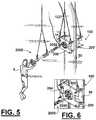
- FIG. 5is a perspective view illustrating the step of hot tapping one or more of the nested tubulars.
- FIG. 6is a closeup perspective view of a hot tap tool attached to a housing.
- FIG. 7is a perspective view illustrating the step of lowering one embodiment of an articulating saw and attaching the articulating saw to the hot tap housing (shown in FIG. 5 ).
- the sawcan be pivotally attached to the hot tap housing via a pin on one side and a support plate on another side.
- the sawalso has an articulating and sliding support join for the rotating saw shaft
- FIG. 8shows the saw attached to the hot tap housing and positioned to make a cut in one of the nested tubulars.
- FIG. 9is a perspective view of a diver using the articulating saw and the diver looking thru the stabilizer and hot tap housing for positioning the saw tip to make a cut.
- FIG. 10is a schematic partial top view of one embodiment illustrating the step of making an opening in a first exterior pipe.
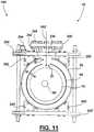
- FIG. 11is a schematic top view of the embodiment shown in FIG. 10 schematically illustrating the step of making an opening in the second pipe.
- FIG. 12is a schematic top view of the embodiment shown in FIG. 10 illustrating the step of hot tapping of a third interior pipe.
- FIG. 13is a schematic top view of the embodiment shown in FIG. 10 schematically illustrating the step of making an opening in the third pipe.
- FIG. 14is a perspective view of one embodiment of an articulating drill system where the system is swung away from the plate.
- FIG. 15is a perspective view of the articulating drill system of FIG. 14 where the system is connected to the plate, perpendicular to same and in the center of main plate opening.
- FIG. 16is a top view of the articulating drill system of FIG. 14 .
- FIG. 17is a top view of the articulating drill system of FIG. 14 where the system is connected to the plate, perpendicular to same and in the center of main plate opening with the drill tip having passed through main plate opening.
- FIG. 18is a top view of the articulating drill system of FIG. 14 where the system is connected to the plate, perpendicular to same and in the center of main plate opening with the double arrow schematically indicating that drill tip can move back and forth through main plate opening.
- FIG. 19is a top view of the articulating drill system of FIG. 14 where the system is connected to the plate, angled from same and in the center of main plate opening with the two sets of double arrows schematically indicating that drill tip can move back and forth through main plate opening along with rotating back and forth.
- FIG. 20is a top view of the articulating drill system of FIG. 16 where the system is connected to the plate, perpendicular to same and offset in the left direction of the arrow from the center of main plate opening.
- FIG. 21is a top view of the articulating drill system of FIG. 16 where the system is connected to the plate, perpendicular to same and offset in the right direction of the arrow from the center of main plate opening.
- FIG. 22is a top view of the articulating drill system of FIG. 16 where the system is connected to the plate, perpendicular to same and offset in the left direction of the arrow from the center of main plate opening and the drill tip is passed through the main opening.
- FIG. 23is a top view of the articulating drill system of FIG. 16 where the system is connected to the plate, angled from a perpendicular to same as indicated by the arrows, where and the drill tip is passed through the main opening.
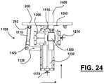
- FIG. 24is a top view of the articulating drill system of FIG. 16 where the system is connected to the plate, perpendicular to same and offset in the right direction of the arrow from the center of main plate opening and the drill tip is passed through the main opening.
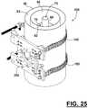
- FIG. 25is a perspective view showing a hot tap housing being placed on the riser piping system.
- FIG. 26is a schematic top view of the embodiment shown in FIG. 25 illustrating the step of hot tapping of a first exterior pipe.
- FIG. 27is a schematic top view of the embodiment shown in FIG. 25 schematically illustrating the step of making an opening in the first exterior pipe.
- FIG. 28is a schematic top view of the embodiment shown in FIG. 25 illustrating the step of hot tapping of a second interior pipe wherein the second interior pipe is concentrically located within the first pipe.
- FIG. 29is a schematic top view of the embodiment shown in FIG. 25 illustrating the step of hot tapping of a second interior pipe wherein the second interior pipe is non-concentrically located (angularly offset from a perpendicular) within the first pipe.
- FIG. 30is a schematic top view of the embodiment shown in FIG. 25 schematically illustrating the step of making an opening in the second pipe.
- FIG. 31is a schematic top view of the embodiment shown in FIG. 25 illustrating the step of hot tapping of a third interior pipe wherein the third interior pipe is concentrically located within the first pipe.
- FIG. 32is a schematic top view of the embodiment shown in FIG. 25 illustrating the step of hot tapping of a third interior pipe wherein the third interior pipe is non-concentrically located (angularly offset from a perpendicular) within the first pipe.
- FIG. 33is a schematic top view of the embodiment shown in FIG. 25 schematically illustrating the step of making an opening in the third pipe.
- FIG. 34is a schematic top view of the embodiment shown in FIG. 25 illustrating the step of hot tapping of a fourth pipe or tubing where the hot tapping tool is angularly offset from a perpendicular to assist in making the hot tapping seal between the tip and the pipe along with pushing the fourth pipe or tubing back, and to a location where it contacts the third interior pipe and enough backward resistance by the fourth pipe or tubing to maintain a good seal between the tip of the hot tap tool and the surface of the fourth pipe or tubing.
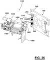
- FIG. 35is a top view of the preferred embodiment of an articulating drill system for making openings through the different pipes shown swiveled out of the way of the clamp where the system is connected to the plate, angled from same and in the center of main plate opening with the two sets of double arrows schematically indicating that drill tip can move back and forth through main plate opening along with rotating back and forth.
- FIG. 36is a perspective view of the articulating drill system of FIG. 35 .
- FIG. 37is a perspective view of the articulating drill system of FIG. 35 shown in position to make a cut through one of the pipes, where the system is connected to the plate, perpendicular to same and in the center of main plate opening with the double arrow schematically indicating that drill tip can move back and forth through main plate opening.
- FIG. 38is a top view of the articulating drill system of FIG. 37 where the drill tip has been moved in a position to make a cut and the stabilizer has been attached to stabilize the drill tip when making a cut.
- FIG. 39is a top view of the articulating drill system shown in the position of FIG. 37 where the drill tip has been moved through the plate (and the articulating joint of the stabilizer) and towards an item to be cut.
- FIG. 40is a top view of the articulating drill system of FIG. 37 , where the system is connected to the plate, perpendicular to same and offset in the right direction of the arrow from the center of main plate opening, and where the drill tip (and the articulating joint of the drill shaft stabilizer) has been shifted to the right from a perpendicular and the drill tip has been moved in a position to make a cut at such angle.
- FIG. 41is a top view of the articulating drill system shown in the position of FIG. 40 , where the system is connected to the plate, perpendicular to same and offset in the right direction of the arrow from the center of main plate opening and the drill tip is passed through the main opening, where the drill tip has been moved through the plate (and the articulating joint of the stabilizer) and towards an item to be cut.
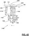
- FIG. 42is a top view of the articulating drill system of FIG. 40 , where the system is connected to the plate, perpendicular to same and offset in the left direction of the arrow from the center of main plate opening, and where the drill tip (and the articulating joint of the drill shaft stabilizer) has been shifted to the left from a perpendicular and the drill tip has been moved in a position to make a cut at such angle.
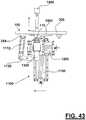
- FIG. 43is a top view of the articulating drill system shown in the position of FIG. 42 , where the system is connected to the plate, perpendicular to same and offset in the left direction of the arrow from the center of main plate opening and the drill tip is passed through the main opening, and where the drill tip has been moved through the plate (and the articulating joint of the stabilizer) and towards an item to be cut.
- FIG. 44is a top view of the articulating drill system of FIG. 35 , where the system is connected to the plate, angled from a perpendicular to same as indicated by the arrows, where and the drill tip is passed through the main opening, and where the drill tip (along with the articulating joint of the stabilizer) has been angled from a perpendicular and the drill tip has been moved in a position to make a cut at such angle, and the stabilizer joint has also angled to allow the drill shaft to angle.
- the systemcan be angled in the opposite angular direction.
- FIG. 45is a top view of the articulating drill system, where the system is connected to the plate, angled from a perpendicular to same as indicated by the arrows, where and the drill tip is passed through the main opening, and where the drill tip has been moved through the plate (and the articulating joint of the stabilizer) and towards an item to be cut.
- FIG. 46is a perspective view of a stabilizer system for the drill shaft and bit.
- FIG. 47is an exploded view of the stabilizer system of FIG. 46 .
- FIGS. 48, 49, and 50are front, side and top views of the stabilizer system of FIG. 46 .
- FIG. 1shows a damaged marine platform 1 .
- the platform 1can be any offshore or marine platform such as a drilling platform, production platform or the like. Such a platform is normally supported by an underwater jacket 4 that is anchored to seabed 2 .
- the upper 5can be separated from jacket 4 by wind and wave action at water surface area 3 .
- Upper 5can be any known above water upper such as drilling (e.g., derrick 7 ) or production structures having one or more decks 6 .
- tubulars 50can remain under pressure though bent at bends 8 as shown. Often, multiple nested tubulars are present.
- One embodimentincludes an articulating drill system 1100 which can be used in the process of hot tapping a string of a plurality of pipes or tubing system.
- the plurality of pipescan include first pipe 50 , second pipe 60 , third pipe 70 , and fourth pipe or tubing 80 . Between first and second pipes is annular space 62 . Between second and third pipes is annular space 72 . Between third and fourth pipes is annular space 82 (see FIGS. 9 and 10 ).
- articulating drill systemcan be used with a hot tap system 10 , which can include adjustable clamp 100 (see FIGS. 2-24 ).
- hot tap system 10can include a plate 200 and one or more chains 150 .
- adjustable clamp 100can include first and second plates 200 , 200 ′ and are threadably connected to each other and can be frictionally connected to a pipe.
- FIG. 2is a perspective view illustrating the step of lowering a hot tap housing 100 (two plate embodiment) and a diver 9 attaching the housing to one of the riser piping systems (e.g. nested tubulars 50 , 60 , 70 , 80 ) below the bend 8 in the riser 50 , 60 , 70 , 80 .
- FIG. 3is a perspective view illustrating the step of the diver 9 tightening the hot tap housing 100 (two plate embodiment) below the bend in the riser.
- FIG. 1is a perspective view illustrating the step of lowering a hot tap housing 100 (two plate embodiment) and a diver 9 attaching the housing to one of the riser piping systems (e.g. nested tubulars 50 , 60 , 70 , 80 ) below the bend 8 in the riser 50 , 60 , 70 , 80 .
- FIG. 3is a perspective view illustrating the step of the diver 9 tightening the hot tap housing 100 (two plate embodiment) below the bend in the riser.
- FIG. 4is a perspective view illustrating the step of lowering to a diver 9 (from a surface vessel, not shown) the hot tap tool 2000 along with a hot tap tip and housing which will be attached to the hot tap housing 100 for hot tapping one or more of the nested tubulars 50 , 60 , 70 , 80 .
- FIG. 5is a perspective view illustrating the step of a diver 9 hot tapping one or more of the nested tubulars 50 , 60 , 70 , 80 where the hot tap tool is rotatively connected to the circular thrust/articulating plate at a selected rotational position.
- the one or more windows in the thrust plateallow the user (e.g. diver 9 ) to see the tip of the hot tap tool 2000 to obtain a good position between the hot tap tip and the nested tubular 50 or 60 or 70 or 80 being hot tapped.
- FIG. 6is a closeup perspective view of hot tap tool 2000 after being connected to the hot tap housing 100 .
- FIG. 7is a perspective view illustrating the step of lowering the articulating saw 1100 to a diver 9 for use in the hot tapping process.
- the diver 9is shown attaching the articulating saw 1100 to the hot tap housing 100 .
- the saw 1100can be pivotally attached to the hot tap housing 100 via a pin on one side and a support plate on another side.
- the saw 1100also has an articulating and sliding support join for the rotating saw shaft.
- FIG. 8shows the saw 1100 attached to the hot tap housing 100 and positioned to make a cut in one of the nested tubulars 50 , 60 , 70 , 80 .
- FIG. 9is a closeup perspective view of a diver 9 using the hot tap tool 2000 .
- FIG. 8is a perspective view of a diver 9 using the articulating saw 1100 .
- first plate 200can comprise first side 210 , second side 220 , a main opening 230 , and a plurality of openings 240 for supporting a compression plate.
- Main opening 230is designed to allow access through first plate 200 (from first side 210 and through second side 220 ) (see FIGS. 2-24 ).
- drill system 1100can be swung (e.g., pivoted on pin 294 ) out of the way so that diver 9 can use hot tapping tool 200 without drill system 1100 being in the way. Also between steps of hot tapping nested tubulars, articulating drill system 1100 can remain attached to outside pipe 50 (e.g., by being pivotally attached to pin 294 of hot tap clamp 100 which is connected to pipe 50 ).
- one embodiment articulating drill system 1100can include first arm 1110 , second arm 1120 , base 1150 , and connection plate 1500 .
- First arm 1110can be pivotally connected to second arm 1120 .
- Second arm 1120can be pivotally connected to base 1150 .
- Base 1150can be pivotally connected to connection plate 1500 .
- Drill 1300can be attached to base 1150 .
- Drill 1300can comprise motor 1320 and cutting tip 1400 which is rotationally connected to motor 1320 .
- Longitudinal track system 1160can allow controlled longitudinal movement (e.g., along the longitudinal direction of base 1150 ) of drill 1300 such as by a screw and thread system.
- Track system 1160can include a quick release/quick lock system which longitudinally locks the position of drill 1300 relative to base 1150 .
- Perpendicular track system 1200can allow controlled perpendicular movement (e.g., perpendicular to the longitudinal direction of base 1150 ) of drill 1300 such as by a screw and thread system.
- Track system 1200can include a quick release/quick lock system which perpendicularly locks the position of drill 1300 relative to base 1150 .
- Longitudinal and perpendicular track systems 1160 and 1200can respectively longitudinally and perpendicularly adjust the position of drill 1300 and tip 1400 .
- Drill system 1100can be pivotally connected to first plate 200 , such as by pin 294 .
- Connection plate 1500can be used to partially positionally lock drill system 1100 relative to first plate 200 . Even when partially locked, drill 1300 can be pivoted relative to first plate 200 through pivoting joint 1510 . Quick release/quick lock 1550 when unlocked allows for pivoting. However, locking quick release/quick lock 1550 prevents further pivoting movement of drill 1300 .
- FIG. 10is a schematic top view schematically illustrating the step of making an opening 51 in the first exterior pipe 50 .
- FIG. 11is a schematic top view schematically illustrating the step of making an opening 61 in the second pipe 60 .
- FIG. 12is a schematic top view of hot tapping system 10 illustrating the step of hot tapping a third interior pipe 70 .
- FIG. 13is a schematic top view of system 10 illustrating the step of hot tapping a fourth pipe or tubing 80 where the hot tapping tool 2000 is angularly offset (by angle theta) from a perpendicular to assist in making the hot tapping seal between the tip 2010 and the pipe 80 , along with the step of using a second tool 3000 to provide support for the tubing 80 when making a seal between the hot tapping tool tip 2010 and the tubing 80 .
- FIGS. 14-15are perspective views of one embodiment of an articulating drill system 1100 for making openings through the different pipes with drill system 1100 shown swiveled out of the way of the clamp 100 .
- FIG. 16is a top view of the articulating drill system 1100 shown in the same position as FIG. 14 .
- FIG. 17is a top view of the articulating drill 100 in the position of FIG. 15 .
- FIG. 18is a top view of articulating drill system 1100 with the double arrows indicating that drill tip 1400 can move back and forth through plate 200 .
- FIG. 19is a top view of articulating drill system 1100 where the drill tip 1400 has been angled from a perpendicular and the drill tip 1400 has been moved in a position to make a cut at such angle.
- FIG. 20is a top view of the articulating drill system 1100 where the system is connected to the plate 200 , perpendicular to same and offset in the left direction of the arrow from the center of main plate opening 230 .
- FIG. 21is a top view of the articulating drill system 1100 where the system is connected to the plate 200 , perpendicular to same and offset in the right direction of the arrow from the center of main plate opening 230 .
- FIG. 22is a top view of the articulating drill system 1100 where the system is connected to the plate, perpendicular to same and offset in the left direction of the arrow from the center of main plate opening 230 and the drill tip 1400 is passed through the main opening 230 .
- FIG. 23is a top view of the articulating drill system 1100 where the system is connected to the plate 200 , angled from a perpendicular to same as indicated by the arrows, where and the drill tip 1400 is passed through the main opening 230 .
- FIG. 24is a top view of the articulating drill system 1100 where the system is connected to the plate 200 , perpendicular to same and offset in the right direction of the arrow from the center of main plate opening 230 and the drill tip 1400 is passed through the main opening 230 .
- FIG. 25is a perspective view showing a hot tap housing 100 being placed on the riser piping system.
- FIG. 26is a schematic top view of hot tap housing 100 generally illustrating the step of hot tapping of a first exterior pipe 50 .
- FIG. 27is a schematic top view of articulating saw system 1100 schematically illustrating the step of making an opening in the first exterior pipe 50 .
- FIG. 28is a schematic top view of a hot tap housing 100 illustrating the step of hot tapping of a second interior pipe 60 wherein the second interior pipe is concentrically located within the first pipe.
- FIG. 29is a schematic top view of hot tap housing 100 illustrating the step of hot tapping of a second interior pipe 60 wherein the second interior pipe 60 is non-concentrically located (angularly offset from a perpendicular) within the first pipe 50 .
- FIG. 30is a schematic top view of the articulating saw system 1100 schematically illustrating the step of making an opening in the second pipe 60 .
- FIG. 31is a schematic top view showing hot tap housing 100 hot tapping a third interior pipe 70 wherein the third interior pipe 70 is concentrically located within the first pipe 50 .
- FIG. 32schematically shows hot tap housing being used to hot tap third interior pipe 70 wherein the third interior pipe 70 is non-concentrically located (angularly offset from a perpendicular) within the first pipe 50 .
- FIG. 33is a schematic top view of articulating saw system 1100 schematically illustrating the step of making an opening in the third pipe 70 .
- FIG. 34is a schematic top view showing hot tap housing 100 illustrating the step of hot tapping of a fourth pipe or tubing 80 where the hot tapping tool 2000 is angularly offset from a perpendicular to assist in making the hot tapping seal between the tip and the pipe along with pushing the fourth pipe or tubing 80 back, and to a location where it contacts the third interior pipe 70 and enough backward resistance by the fourth pipe or tubing 80 to maintain a good seal between the tip 2010 of the hot tap tool 2000 and the surface of the fourth pipe or tubing 80 .
- FIG. 35is a top view of the preferred embodiment of an articulating drill system 1100 for making openings through the different pipes (e.g., pipes 50 , 60 , and 70 ) shown swiveled out of the way of the clamp where the system 1100 is connected to the plate 200 , angled from same and in the center of main plate opening with the two sets of double arrows schematically indicating that drill tip can move back and forth through main plate opening along with rotating back and forth.
- FIG. 36is a perspective view of the articulating drill system 1100 .
- FIG. 37is a perspective view of articulating drill system 1100 shown in a centered position to make a cut through one of the pipes (e.g., pipes 50 , 60 , and 70 ), where the system is connected to the plate 200 , perpendicular to same and in the center of main plate opening with the double arrow schematically indicating that drill tip 1400 can move back and forth through main plate opening.
- the pipese.g., pipes 50 , 60 , and 70
- FIG. 38is a top view of the articulating drill system 1100 where the drill tip 1400 has been moved in a position to make a cut and the stabilizer 110 has been attached to stabilize the drill tip 1400 when making a cut.
- FIG. 39is a top view of the articulating drill system 1100 (shown in the position of FIG. 38 ), where the drill tip 1400 has been moved through the plate 200 (and the articulating joint of the stabilizer 110 ) and towards an item to be cut (e.g., pipes 50 , 60 , and 70 ).
- an item to be cute.g., pipes 50 , 60 , and 70 .
- FIG. 40is a top view of the articulating drill system 1100 , where the system 1100 is connected to the plate 200 , perpendicular to same and offset in the right direction of the arrow from the center of main plate opening, and where the drill tip 1400 (and the articulating joint of the drill shaft stabilizer 110 ) has been shifted to the right from a perpendicular and the drill tip 1400 has been moved in a position to make a cut at such shifted position.
- FIG. 41is a top view of the articulating drill system 1100 (shown in the position of FIG.
- FIG. 42is a top view of the articulating drill system 1100 , where the system 1100 is connected to the plate 200 , perpendicular to same and offset in the left direction of the arrow from the center of main plate opening, and where the drill tip 1400 (and the articulating joint of the drill shaft stabilizer 110 ) has been shifted to the left from a perpendicular, and the drill tip 1400 has been moved in a position to make a cut at such angle.
- FIG. 43is a top view of the articulating drill system 1100 (shown in the position of FIG.
- FIG. 44is a top view of the articulating drill system 1100 , where the system 1100 is connected to the plate 200 , angled from a perpendicular to same as indicated by the arrow, where and the drill tip 1400 is passed through the main opening, and where the drill tip 1400 (along with the articulating joint of the stabilizer 110 ) has been angled from a perpendicular, and the stabilizer joint 110 has also angled to allow the drill shaft to angle.
- the systemcan be angled in the opposite angular direction.
- FIG. 45is a top view of the articulating drill system 1100 (shown in the position of FIG.
- FIG. 46is a perspective view of a stabilizer system 110 for the drill shaft and bit 1400 .
- FIGS. 48, 49, and 50are front, side and top views of the stabilizer system 110 of FIG. 46 .
- FIG. 47is an exploded view of the stabilizer system 110 of FIG. 46 .
- Stabilizer system 110includes a plate 111 having central slot 114 and plate openings 112 , 113 .
- the plate 111is clamped or sandwiched in between housing sections 117 , 125 with bearing 115 in between.
- Bearing 115is an annular bearing that is sized and shaped to fit cavity 118 of housing section 117 while enabling bearing 115 to pivot with hot tapping tool that passes through opening 116 .
- Clamps or bolts 121 , 122can be loosened to allow bearing 115 (and a hot tapping tool) to pivot while being supported by the bearing 115 and the housing sections and plate 111 , 117 , 125 .
- Each clamp or boltcan have a lever or handle 123 or 124 for enabling a user (e.g.
- Housing section 125has surface 130 which slides upon surface 134 of plate 111 .
- Housing section 125has surface 131 which slides upon surface 135 of plate 111 .
- Housing section 132slides upon rear surface 136 of plate 111 .
- a usersuch as diver 9 can loosen bolts or clamps 121 , 122 and slide the housing sections 117 , 125 laterally relative to plate 111 .
- the plate 111can be bolted to a selected part of clamp 100 using bolted connections at plate openings 112 , 113 .
- the housing section 125has internally threaded openings 126 , 127 that accept threaded portions 138 or 139 of bolts 121 or 122 .
Landscapes
- Engineering & Computer Science (AREA)
- Geology (AREA)
- Life Sciences & Earth Sciences (AREA)
- Mining & Mineral Resources (AREA)
- Mechanical Engineering (AREA)
- General Life Sciences & Earth Sciences (AREA)
- Environmental & Geological Engineering (AREA)
- Physics & Mathematics (AREA)
- Geochemistry & Mineralogy (AREA)
- Fluid Mechanics (AREA)
- General Engineering & Computer Science (AREA)
- Pipe Accessories (AREA)
- Processing Of Stones Or Stones Resemblance Materials (AREA)
- Drilling And Boring (AREA)
- Placing Or Removing Of Piles Or Sheet Piles, Or Accessories Thereof (AREA)
- Joining Of Building Structures In Genera (AREA)
- Perforating, Stamping-Out Or Severing By Means Other Than Cutting (AREA)
- Cultivation Receptacles Or Flower-Pots, Or Pots For Seedlings (AREA)
- Earth Drilling (AREA)
Abstract
Description
| LIST OF REFERENCE NUMERALS |
| Reference Number | Description |
| 1 | damaged platform |
| 2 | seabed |
| 3 | water surface |
| 4 | jacket |
| 5 | upper |
| 6 | deck area |
| 7 | derrick |
| 8 | bend |
| 9 | driver |
| 10 | system |
| 50 | first pipe |
| 51 | opening |
| 60 | second pipe |
| 61 | opening |
| 62 | annular space between first and second pipes |
| 70 | third pipe |
| 71 | opening |
| 72 | annular space between second and third pipes |
| 80 | fourth pipe or tubing |
| 82 | annular space between third and fourth pipes |
| 84 | interior of fourth pipe or tubing |
| 100 | clamp |
| 110 | stabilizer system |
| 111 | plate |
| 112 | plate opening |
| 113 | plate opening |
| 114 | plate slot |
| 115 | annular bearing |
| 116 | central opening |
| 117 | first bearing housing section |
| 118 | cavity |
| 119 | opening |
| 120 | opening |
| 121 | bolt |
| 122 | bolt |
| 123 | lever/handle |
| 124 | lever/handle |
| 125 | second bearing housing section |
| 126 | internally threaded opening |
| 127 | internally threaded opening |
| 128 | upper part |
| 129 | lower part |
| 130 | upper flat surface |
| 131 | lower flat surface |
| 132 | middle flat surface |
| 133 | opening |
| 134 | upper flat plate surface |
| 135 | lower flat plate surface |
| 136 | rear flat plate surface |
| 137 | front flat plate surface |
| 138 | threaded portion |
| 139 | threaded portion |
| 150 | chain |
| 200 | first plate |
| 210 | first side |
| 220 | second side |
| 230 | main opening |
| 240 | plurality of openings |
| 294 | pin |
| 299 | pin |
| 500 | compression plate |
| 510 | first side |
| 520 | second side |
| 530 | plurality of support openings |
| 550 | main opening |
| 551 | offset from centerline |
| 552 | arrow |
| 554 | arrow |
| 560 | tapered area |
| 580 | view opening |
| 582 | view opening |
| 584 | view opening |
| 586 | view opening |
| 800 | swivel nut |
| 1100 | articulating drill system/articulating saw |
| 1110 | first arm |
| 1120 | second arm |
| 1122 | pivot connection between first and second arms |
| 1150 | base |
| 1152 | pivot connection between second arm and base |
| 1160 | longitudinal track system |
| 1170 | handle for longitudinal track system |
| 1200 | perpendicular track system |
| 1210 | handle for perpendicular track system |
| 1300 | drill |
| 1320 | drill motor |
| 1400 | cutting tip |
| 1410 | arrow |
| 1420 | arrow |
| 1500 | connection plate |
| 1502 | plurality of openings |
| 1510 | pivoting joint between connection plate and base |
| 1550 | quick release/quick lock for pivoting joint |
| 2000 | hot tapping system |
| 2010 | tip |
| 2050 | barrel |
| 2100 | hot tap drill |
| 2110 | drill bit |
Claims (17)
Priority Applications (1)
| Application Number | Priority Date | Filing Date | Title |
|---|---|---|---|
| US16/030,802US10619439B2 (en) | 2009-03-31 | 2018-07-09 | Articulating drill method and apparatus for cutting openings in nested strings of underwater piping and or tubing for overturned wells or platforms |
Applications Claiming Priority (5)
| Application Number | Priority Date | Filing Date | Title |
|---|---|---|---|
| US16547509P | 2009-03-31 | 2009-03-31 | |
| US12/751,418US8616811B2 (en) | 2009-03-31 | 2010-03-31 | Articulating drill method and apparatus for cutting openings in nested strings of underwater piping and/or tubing for overturned wells or platforms |
| US14/144,942US9482380B2 (en) | 2009-03-31 | 2013-12-31 | Articulating drill method and apparatus for cutting openings in nested strings of underwater piping and or tubing for overturned wells or platforms |
| US15/340,073US10018005B2 (en) | 2009-03-31 | 2016-11-01 | Articulating drill method and apparatus for cutting openings in nested strings of underwater piping and or tubing for overturned wells or platforms |
| US16/030,802US10619439B2 (en) | 2009-03-31 | 2018-07-09 | Articulating drill method and apparatus for cutting openings in nested strings of underwater piping and or tubing for overturned wells or platforms |
Related Parent Applications (1)
| Application Number | Title | Priority Date | Filing Date |
|---|---|---|---|
| US15/340,073ContinuationUS10018005B2 (en) | 2009-03-31 | 2016-11-01 | Articulating drill method and apparatus for cutting openings in nested strings of underwater piping and or tubing for overturned wells or platforms |
Publications (2)
| Publication Number | Publication Date |
|---|---|
| US20190040704A1 US20190040704A1 (en) | 2019-02-07 |
| US10619439B2true US10619439B2 (en) | 2020-04-14 |
Family
ID=42782649
Family Applications (13)
| Application Number | Title | Priority Date | Filing Date |
|---|---|---|---|
| US12/751,418Active2032-09-24US8616811B2 (en) | 2009-03-31 | 2010-03-31 | Articulating drill method and apparatus for cutting openings in nested strings of underwater piping and/or tubing for overturned wells or platforms |
| US12/751,200Active2032-04-30US8622078B2 (en) | 2009-03-31 | 2010-03-31 | Apparatus of hot tapping multiple coaxial or nested strings of underwater piping and/or tubing for overturned wells or platforms |
| US13/248,781Expired - Fee RelatedUS8333211B2 (en) | 2009-03-31 | 2011-09-29 | Method and apparatus of hot tapping multiple coaxial or nested strings of underwater piping and/or tubing for overturned wells or platforms |
| US13/717,890ActiveUS8707979B2 (en) | 2009-03-31 | 2012-12-18 | Method and apparatus of hot tapping multiple coaxial or nested strings of underwater piping and/or tubing for overturned wells or platforms |
| US14/144,942Expired - Fee RelatedUS9482380B2 (en) | 2009-03-31 | 2013-12-31 | Articulating drill method and apparatus for cutting openings in nested strings of underwater piping and or tubing for overturned wells or platforms |
| US14/263,088ActiveUS9194525B2 (en) | 2009-03-31 | 2014-04-28 | Method and apparatus of hot tapping multiple coaxial or nested strings of underwater piping and/or tubing for overturned wells or platforms |
| US14/950,908ActiveUS9851038B2 (en) | 2009-03-31 | 2015-11-24 | Method and apparatus of hot tapping multiple coaxial or nested strings of underwater piping and/or tubing for overturned wells or platforms |
| US15/340,073Active2030-05-11US10018005B2 (en) | 2009-03-31 | 2016-11-01 | Articulating drill method and apparatus for cutting openings in nested strings of underwater piping and or tubing for overturned wells or platforms |
| US15/853,613ActiveUS10253587B2 (en) | 2009-03-31 | 2017-12-22 | Method and apparatus of hot tapping multiple coaxial or nested strings of underwater piping and/or tubing for overturned wells or platforms |
| US16/030,802Expired - Fee RelatedUS10619439B2 (en) | 2009-03-31 | 2018-07-09 | Articulating drill method and apparatus for cutting openings in nested strings of underwater piping and or tubing for overturned wells or platforms |
| US16/377,431Expired - Fee RelatedUS10851605B2 (en) | 2009-03-31 | 2019-04-08 | Method and apparatus of hot tapping multiple coaxial or nested strings of underwater piping and/or tubing for overturned wells or platforms |
| US17/106,369ActiveUS11473384B2 (en) | 2009-03-31 | 2020-11-30 | Method and apparatus of hot tapping multiple coaxial or nested strings of underwater piping and/or tubing for overturned wells or platforms |
| US17/967,987AbandonedUS20230095591A1 (en) | 2009-03-31 | 2022-10-18 | Method and apparatus of hot tapping multiple coaxial or nested strings of underwater piping and/or tubing for overturned wells or platforms |
Family Applications Before (9)
| Application Number | Title | Priority Date | Filing Date |
|---|---|---|---|
| US12/751,418Active2032-09-24US8616811B2 (en) | 2009-03-31 | 2010-03-31 | Articulating drill method and apparatus for cutting openings in nested strings of underwater piping and/or tubing for overturned wells or platforms |
| US12/751,200Active2032-04-30US8622078B2 (en) | 2009-03-31 | 2010-03-31 | Apparatus of hot tapping multiple coaxial or nested strings of underwater piping and/or tubing for overturned wells or platforms |
| US13/248,781Expired - Fee RelatedUS8333211B2 (en) | 2009-03-31 | 2011-09-29 | Method and apparatus of hot tapping multiple coaxial or nested strings of underwater piping and/or tubing for overturned wells or platforms |
| US13/717,890ActiveUS8707979B2 (en) | 2009-03-31 | 2012-12-18 | Method and apparatus of hot tapping multiple coaxial or nested strings of underwater piping and/or tubing for overturned wells or platforms |
| US14/144,942Expired - Fee RelatedUS9482380B2 (en) | 2009-03-31 | 2013-12-31 | Articulating drill method and apparatus for cutting openings in nested strings of underwater piping and or tubing for overturned wells or platforms |
| US14/263,088ActiveUS9194525B2 (en) | 2009-03-31 | 2014-04-28 | Method and apparatus of hot tapping multiple coaxial or nested strings of underwater piping and/or tubing for overturned wells or platforms |
| US14/950,908ActiveUS9851038B2 (en) | 2009-03-31 | 2015-11-24 | Method and apparatus of hot tapping multiple coaxial or nested strings of underwater piping and/or tubing for overturned wells or platforms |
| US15/340,073Active2030-05-11US10018005B2 (en) | 2009-03-31 | 2016-11-01 | Articulating drill method and apparatus for cutting openings in nested strings of underwater piping and or tubing for overturned wells or platforms |
| US15/853,613ActiveUS10253587B2 (en) | 2009-03-31 | 2017-12-22 | Method and apparatus of hot tapping multiple coaxial or nested strings of underwater piping and/or tubing for overturned wells or platforms |
Family Applications After (3)
| Application Number | Title | Priority Date | Filing Date |
|---|---|---|---|
| US16/377,431Expired - Fee RelatedUS10851605B2 (en) | 2009-03-31 | 2019-04-08 | Method and apparatus of hot tapping multiple coaxial or nested strings of underwater piping and/or tubing for overturned wells or platforms |
| US17/106,369ActiveUS11473384B2 (en) | 2009-03-31 | 2020-11-30 | Method and apparatus of hot tapping multiple coaxial or nested strings of underwater piping and/or tubing for overturned wells or platforms |
| US17/967,987AbandonedUS20230095591A1 (en) | 2009-03-31 | 2022-10-18 | Method and apparatus of hot tapping multiple coaxial or nested strings of underwater piping and/or tubing for overturned wells or platforms |
Country Status (7)
| Country | Link |
|---|---|
| US (13) | US8616811B2 (en) |
| EP (1) | EP2414124B1 (en) |
| AU (1) | AU2010236832B2 (en) |
| DK (1) | DK2414124T3 (en) |
| MX (1) | MX2011010394A (en) |
| NZ (1) | NZ595582A (en) |
| WO (2) | WO2010120516A2 (en) |
Cited By (1)
| Publication number | Priority date | Publication date | Assignee | Title |
|---|---|---|---|---|
| US20230095591A1 (en)* | 2009-03-31 | 2023-03-30 | Aes-Eot Equipment Holdings, Llc | Method and apparatus of hot tapping multiple coaxial or nested strings of underwater piping and/or tubing for overturned wells or platforms |
Families Citing this family (32)
| Publication number | Priority date | Publication date | Assignee | Title |
|---|---|---|---|---|
| US8091283B2 (en)* | 2007-04-20 | 2012-01-10 | Opcon International Holdings, L.P. | Adjustable spindle arrangement for door operating apparatus retrofit kit |
| US20080256869A1 (en) | 2007-04-20 | 2008-10-23 | Opcon Manufacturing Systems, Inc. | Sealing arrangement for door operating apparatus retrofit kit |
| US7938137B2 (en) | 2007-11-27 | 2011-05-10 | Blowout Tools, Inc. | Method of direct hot tapping into a multiple production string without removing outer layers of casing |
| US9028162B1 (en) | 2008-11-10 | 2015-05-12 | Hurricane Safety Systems, Llc | Quick release system and method |
| US8833464B2 (en)* | 2010-05-26 | 2014-09-16 | General Marine Contractors LLC | Method and system for containing uncontrolled flow of reservoir fluids into the environment |
| US8651133B1 (en)* | 2010-10-06 | 2014-02-18 | Douglas G. Buttz | Tap safety device |
| CN102451924B (en)* | 2010-10-20 | 2016-08-03 | 中车洛阳机车有限公司 | Explosion-proof anti-contamination drilling machine |
| EP2633154A2 (en)* | 2010-10-28 | 2013-09-04 | Gulfstream Services, Inc. | Method and apparatus for evacuating hydrocarbons from a distressed well |
| CN106377294B (en) | 2010-12-21 | 2020-02-18 | 史赛克公司 | Control module for powered surgical tool including active seal |
| EP2776664A4 (en) | 2011-11-07 | 2016-10-05 | Oklahoma Safety Equipment Company Inc | Pressure relief device, system, and method |
| US8739902B2 (en) | 2012-08-07 | 2014-06-03 | Dura Drilling, Inc. | High-speed triple string drilling system |
| KR101355497B1 (en)* | 2012-08-14 | 2014-02-12 | 주식회사 에네스지 | Device for removal of plug of turbine rotor bore |
| NO337131B1 (en)* | 2012-12-28 | 2016-01-25 | 1Diamond Llc | A sawing system, a support structure for a saw and a sawmill swap unit |
| JP5593374B2 (en)* | 2012-12-28 | 2014-09-24 | 木本産業株式会社 | Drilling tools |
| US9829141B2 (en)* | 2014-02-28 | 2017-11-28 | Hydra-Stop Llc | Linestops, nozzles and completion plugs for installation in pressurized pipes |
| US9506594B2 (en)* | 2014-11-24 | 2016-11-29 | Yanbu Aramco Sinopec Refining Company Ltd. (YASREF) | Method for hot-tap tie in for large diameter pipes |
| CN104439419A (en)* | 2014-11-28 | 2015-03-25 | 天津安顺成金属制品有限公司 | Rapid clamping and drilling mould for machining of side hole of round steel |
| US10245654B2 (en)* | 2015-08-17 | 2019-04-02 | Geoffrey S. Craychee | Truck clutch brake cutter |
| US10408386B2 (en)* | 2015-08-21 | 2019-09-10 | Fab-Tech, Inc. | Hot tap system and method for coated ductwork |
| CA3003887C (en) | 2015-11-06 | 2024-06-25 | Oklahoma Safety Equipment Company, Inc. | Rupture disc device and method of assembly thereof |
| US9963950B2 (en)* | 2015-11-20 | 2018-05-08 | Cameron International Corporation | Multi-function tool for a drilling riser |
| US10989348B2 (en)* | 2016-09-01 | 2021-04-27 | Oceaneering International, Inc. | System for and method of sealing a flowline with a metal seal after hot tapping |
| US10982508B2 (en)* | 2016-10-25 | 2021-04-20 | Stress Engineering Services, Inc. | Pipeline insulated remediation system and installation method |
| CN109047826A (en)* | 2018-07-28 | 2018-12-21 | 宁国市金优机械配件有限公司 | A kind of hot-melting connection device |
| JP7062575B2 (en)* | 2018-11-19 | 2022-05-06 | 株式会社エムオーテック | Jig for drilling holes in steel pipes and drilling methods |
| US10780486B1 (en)* | 2019-08-07 | 2020-09-22 | Valtra Inc. | Notcher |
| CN112846260B (en)* | 2019-11-26 | 2022-03-01 | 北京福田康明斯发动机有限公司 | Hydraulic boring head for machining guide pipe of engine cylinder cover seat ring |
| CN111422330B (en)* | 2020-03-17 | 2022-02-25 | 国网山东省电力公司青岛市黄岛区供电公司 | A magnetic hook type submarine cable lifting device |
| US11376677B2 (en)* | 2020-09-22 | 2022-07-05 | Rogue Fabrication, LLC | Tube notching devices |
| US20250067382A1 (en) | 2023-08-24 | 2025-02-27 | Tdw Delaware, Inc. | Pipeline Service System Including Inspection Tools to Evaluate Pipeline Flow and Assess Performance of Structural Tools during Hot Tapping Operation |
| CN118893257B (en)* | 2024-10-09 | 2024-11-29 | 河北鑫泰管道科技有限公司 | Threaded pipe fitting processing equipment |
| KR102829203B1 (en)* | 2025-03-18 | 2025-07-09 | 주식회사 삼문전력 | Length-adjustable and electromagnetic fixed safety belt support device |
Citations (35)
| Publication number | Priority date | Publication date | Assignee | Title |
|---|---|---|---|---|
| US309085A (en)* | 1884-12-09 | Device for tapping mains | ||
| US351397A (en)* | 1886-10-26 | Mains | ||
| US440856A (en)* | 1890-11-18 | wisehaupt | ||
| US654269A (en)* | 1900-01-20 | 1900-07-24 | Henry Mueller | Tapping-machine. |
| US1279153A (en)* | 1917-05-16 | 1918-09-17 | Arthur W Peterson | Adjustable support for drills and the like. |
| US1294168A (en)* | 1918-08-10 | 1919-02-11 | Stanley Rule & Level Co | Chain-drill. |
| US1596558A (en)* | 1922-09-29 | 1926-08-17 | Boris N Sokoloff | Method and apparatus for amplifying electric currents |
| US1741044A (en)* | 1927-10-26 | 1929-12-24 | Charles R Whipple | Drill stand |
| US1936720A (en)* | 1931-02-14 | 1933-11-28 | Kronheim Jacob | Hanger or bracket |
| US2630151A (en)* | 1950-05-22 | 1953-03-03 | American Mfg Company Inc | Portable track-guided tilt router |
| US2997900A (en)* | 1959-11-09 | 1961-08-29 | Lawrence E Pugsley | Multipurpose tool fixture |
| US3106133A (en)* | 1961-07-10 | 1963-10-08 | Jr Jerry Arpaio | Surface finishing machine for bowling balls |
| US3806691A (en)* | 1972-11-20 | 1974-04-23 | Cammann Mfg Co | Tool positioner |
| US3922107A (en)* | 1973-05-31 | 1975-11-25 | Dwight W Fowler | Sewer tapping method and apparatus |
| US4094612A (en)* | 1976-07-29 | 1978-06-13 | Widder Corporation | Tool mounting apparatus |
| US4152090A (en)* | 1977-09-22 | 1979-05-01 | Johns-Manville Corporation | Hole cutting apparatus utilizing a cylinder saw |
| US4369845A (en)* | 1979-07-26 | 1983-01-25 | Mobell Blowout Services Limited | Oil well blow-out control |
| US4468159A (en)* | 1981-12-07 | 1984-08-28 | Oster Stanley M | Drill press and stand |
| US5118228A (en)* | 1990-12-05 | 1992-06-02 | Story Marvin L | Tubing cutter and coping apparatus |
| US5217073A (en)* | 1991-05-07 | 1993-06-08 | Karsten Bruns | Cut-and-close device for pressure pipes in production and supply installations |
| US5713702A (en)* | 1995-04-13 | 1998-02-03 | Turner; Gordon Henry | Adaptors for a drill stand |
| US5863160A (en)* | 1997-11-06 | 1999-01-26 | Havener; Dennis J. | Portable tool guide |
| US5902077A (en)* | 1998-03-20 | 1999-05-11 | Marking Methods, Inc. | Variable speed universal drilling tapping and reaming machine |
| US6050753A (en)* | 1996-10-15 | 2000-04-18 | Turner; Gordon Henry | Apparatus for mounting a drill on a pipe |
| US6200068B1 (en)* | 1998-02-06 | 2001-03-13 | Sonsub, Inc. | Hot tap fluid blaster apparatus and method of using same |
| US20040118577A1 (en)* | 2002-12-19 | 2004-06-24 | Danny Morissette | Self-supporting pneumatic hammer positioner with universal joint |
| US6761511B2 (en)* | 2001-07-26 | 2004-07-13 | Gordon Henry Turner | Apparatus for mounting a drill on a pipe |
| US7070366B2 (en)* | 2002-07-12 | 2006-07-04 | Hilti Aktiengesellschaft | Drill stand for a core drilling machine |
| US7125206B2 (en)* | 2003-07-14 | 2006-10-24 | Gordon Henry Turner | Apparatus for mounting a drill on a pipe |
| US7231989B2 (en)* | 2001-05-15 | 2007-06-19 | Sandvik Tamrock Oy | Drilling control arrangement |
| WO2008021792A1 (en)* | 2006-08-08 | 2008-02-21 | Shell Oil Company | Subsea hot tap systems and methods |
| US7435041B1 (en)* | 2005-07-19 | 2008-10-14 | Mcgill Ronald L | Hole cutting assembly for pipes and well casings |
| US7607870B2 (en)* | 2006-11-02 | 2009-10-27 | Hughes Jr Robert K | Rotary tube notching apparatus |
| US7832496B2 (en)* | 2007-03-19 | 2010-11-16 | Goei Co., Ltd. | Deep-hole boring machine and deep-hole boring guide device |
| US8333211B2 (en)* | 2009-03-31 | 2012-12-18 | Tetra Applied Technologies, Llc | Method and apparatus of hot tapping multiple coaxial or nested strings of underwater piping and/or tubing for overturned wells or platforms |
Family Cites Families (21)
| Publication number | Priority date | Publication date | Assignee | Title |
|---|---|---|---|---|
| US2911859A (en)* | 1955-04-22 | 1959-11-10 | Lock Joint Pipe Co | Method for tapping pipe |
| DE1811610A1 (en)* | 1968-11-29 | 1970-06-11 | Duerr O Fa | Device for attaching nozzles or similar parts to a pipeline |
| US4332272A (en)* | 1979-08-08 | 1982-06-01 | Wendell David E | Hot tap apparatus and method |
| FR2543257B1 (en)* | 1983-03-24 | 1985-08-09 | Electricite De France | METHOD AND DEVICE FOR CREATING A PIPING IN A CONTROLLED ATMOSPHERE ON A PIPING SYSTEM, IN PARTICULAR A NUCLEAR POWER PLANT PIPING |
| US4936720A (en)* | 1989-09-26 | 1990-06-26 | Fend Industrial Tool Inc. | Compact device for cutting holes in pipe |
| GB9203452D0 (en)* | 1992-02-18 | 1992-04-01 | Periquip Services | Pipe treating method and apparatus |
| JPH09210271A (en)* | 1996-02-05 | 1997-08-12 | Yano Giken Kk | Pipe joint for fluid transport pipe |
| NZ336716A (en)* | 1997-01-09 | 2001-09-28 | Robert Williams Carter | Device for trenchless replacement of underground pipe |
| US6004072A (en)* | 1997-09-10 | 1999-12-21 | Fmc Corporation | Self-orienting subsea flowline tapping arrangement |
| IL124919A (en)* | 1998-06-15 | 2001-01-28 | Ppc Ltd | Pipe tapping |
| US7021325B2 (en)* | 2004-01-08 | 2006-04-04 | Occlude | Valve assembly and method for hot tapping a line |
| KR100624034B1 (en)* | 2004-08-03 | 2006-09-19 | 영 식 김 | Pipe tapping device |
| NO321587B1 (en)* | 2004-10-12 | 2006-06-06 | Statoil Asa | Hot tap staples |
| US7722298B2 (en)* | 2005-11-10 | 2010-05-25 | Larry Rayner Russell | Hot tap machine |
| FR2896298B1 (en)* | 2006-01-13 | 2009-07-17 | Gaz De France Sa | DEVICE AND METHOD FOR INTERVENTION ON A CANALIZATION EQUIPPED WITH A DERIVATION SEAT |
| US8069874B2 (en)* | 2007-02-19 | 2011-12-06 | Cudd Pressure Control, Inc. | System for hot tapping |
| US7552742B2 (en)* | 2007-06-14 | 2009-06-30 | Victaulic Company | Hot tap device |
| US7938137B2 (en)* | 2007-11-27 | 2011-05-10 | Blowout Tools, Inc. | Method of direct hot tapping into a multiple production string without removing outer layers of casing |
| CN102149956B (en)* | 2008-10-27 | 2013-02-20 | 株式会社水研 | Branch device for uninterrupted flow boring |
| CA2973537C (en)* | 2015-01-26 | 2019-03-19 | Suiken Co., Ltd. | Flow-undisrupted process |
| US11391104B2 (en)* | 2020-06-03 | 2022-07-19 | Saudi Arabian Oil Company | Freeing a stuck pipe from a wellbore |
- 2010
- 2010-03-31NZNZ595582Apatent/NZ595582A/ennot_activeIP Right Cessation
- 2010-03-31EPEP10764860.2Apatent/EP2414124B1/ennot_activeNot-in-force
- 2010-03-31USUS12/751,418patent/US8616811B2/enactiveActive
- 2010-03-31DKDK10764860.2Tpatent/DK2414124T3/enactive
- 2010-03-31WOPCT/US2010/029389patent/WO2010120516A2/enactiveApplication Filing
- 2010-03-31USUS12/751,200patent/US8622078B2/enactiveActive
- 2010-03-31WOPCT/US2010/029403patent/WO2010120521A2/enactiveApplication Filing
- 2010-03-31AUAU2010236832Apatent/AU2010236832B2/ennot_activeCeased
- 2010-03-31MXMX2011010394Apatent/MX2011010394A/enactiveIP Right Grant
- 2011
- 2011-09-29USUS13/248,781patent/US8333211B2/ennot_activeExpired - Fee Related
- 2012
- 2012-12-18USUS13/717,890patent/US8707979B2/enactiveActive
- 2013
- 2013-12-31USUS14/144,942patent/US9482380B2/ennot_activeExpired - Fee Related
- 2014
- 2014-04-28USUS14/263,088patent/US9194525B2/enactiveActive
- 2015
- 2015-11-24USUS14/950,908patent/US9851038B2/enactiveActive
- 2016
- 2016-11-01USUS15/340,073patent/US10018005B2/enactiveActive
- 2017
- 2017-12-22USUS15/853,613patent/US10253587B2/enactiveActive
- 2018
- 2018-07-09USUS16/030,802patent/US10619439B2/ennot_activeExpired - Fee Related
- 2019
- 2019-04-08USUS16/377,431patent/US10851605B2/ennot_activeExpired - Fee Related
- 2020
- 2020-11-30USUS17/106,369patent/US11473384B2/enactiveActive
- 2022
- 2022-10-18USUS17/967,987patent/US20230095591A1/ennot_activeAbandoned
Patent Citations (35)
| Publication number | Priority date | Publication date | Assignee | Title |
|---|---|---|---|---|
| US309085A (en)* | 1884-12-09 | Device for tapping mains | ||
| US351397A (en)* | 1886-10-26 | Mains | ||
| US440856A (en)* | 1890-11-18 | wisehaupt | ||
| US654269A (en)* | 1900-01-20 | 1900-07-24 | Henry Mueller | Tapping-machine. |
| US1279153A (en)* | 1917-05-16 | 1918-09-17 | Arthur W Peterson | Adjustable support for drills and the like. |
| US1294168A (en)* | 1918-08-10 | 1919-02-11 | Stanley Rule & Level Co | Chain-drill. |
| US1596558A (en)* | 1922-09-29 | 1926-08-17 | Boris N Sokoloff | Method and apparatus for amplifying electric currents |
| US1741044A (en)* | 1927-10-26 | 1929-12-24 | Charles R Whipple | Drill stand |
| US1936720A (en)* | 1931-02-14 | 1933-11-28 | Kronheim Jacob | Hanger or bracket |
| US2630151A (en)* | 1950-05-22 | 1953-03-03 | American Mfg Company Inc | Portable track-guided tilt router |
| US2997900A (en)* | 1959-11-09 | 1961-08-29 | Lawrence E Pugsley | Multipurpose tool fixture |
| US3106133A (en)* | 1961-07-10 | 1963-10-08 | Jr Jerry Arpaio | Surface finishing machine for bowling balls |
| US3806691A (en)* | 1972-11-20 | 1974-04-23 | Cammann Mfg Co | Tool positioner |
| US3922107A (en)* | 1973-05-31 | 1975-11-25 | Dwight W Fowler | Sewer tapping method and apparatus |
| US4094612A (en)* | 1976-07-29 | 1978-06-13 | Widder Corporation | Tool mounting apparatus |
| US4152090A (en)* | 1977-09-22 | 1979-05-01 | Johns-Manville Corporation | Hole cutting apparatus utilizing a cylinder saw |
| US4369845A (en)* | 1979-07-26 | 1983-01-25 | Mobell Blowout Services Limited | Oil well blow-out control |
| US4468159A (en)* | 1981-12-07 | 1984-08-28 | Oster Stanley M | Drill press and stand |
| US5118228A (en)* | 1990-12-05 | 1992-06-02 | Story Marvin L | Tubing cutter and coping apparatus |
| US5217073A (en)* | 1991-05-07 | 1993-06-08 | Karsten Bruns | Cut-and-close device for pressure pipes in production and supply installations |
| US5713702A (en)* | 1995-04-13 | 1998-02-03 | Turner; Gordon Henry | Adaptors for a drill stand |
| US6050753A (en)* | 1996-10-15 | 2000-04-18 | Turner; Gordon Henry | Apparatus for mounting a drill on a pipe |
| US5863160A (en)* | 1997-11-06 | 1999-01-26 | Havener; Dennis J. | Portable tool guide |
| US6200068B1 (en)* | 1998-02-06 | 2001-03-13 | Sonsub, Inc. | Hot tap fluid blaster apparatus and method of using same |
| US5902077A (en)* | 1998-03-20 | 1999-05-11 | Marking Methods, Inc. | Variable speed universal drilling tapping and reaming machine |
| US7231989B2 (en)* | 2001-05-15 | 2007-06-19 | Sandvik Tamrock Oy | Drilling control arrangement |
| US6761511B2 (en)* | 2001-07-26 | 2004-07-13 | Gordon Henry Turner | Apparatus for mounting a drill on a pipe |
| US7070366B2 (en)* | 2002-07-12 | 2006-07-04 | Hilti Aktiengesellschaft | Drill stand for a core drilling machine |
| US20040118577A1 (en)* | 2002-12-19 | 2004-06-24 | Danny Morissette | Self-supporting pneumatic hammer positioner with universal joint |
| US7125206B2 (en)* | 2003-07-14 | 2006-10-24 | Gordon Henry Turner | Apparatus for mounting a drill on a pipe |
| US7435041B1 (en)* | 2005-07-19 | 2008-10-14 | Mcgill Ronald L | Hole cutting assembly for pipes and well casings |
| WO2008021792A1 (en)* | 2006-08-08 | 2008-02-21 | Shell Oil Company | Subsea hot tap systems and methods |
| US7607870B2 (en)* | 2006-11-02 | 2009-10-27 | Hughes Jr Robert K | Rotary tube notching apparatus |
| US7832496B2 (en)* | 2007-03-19 | 2010-11-16 | Goei Co., Ltd. | Deep-hole boring machine and deep-hole boring guide device |
| US8333211B2 (en)* | 2009-03-31 | 2012-12-18 | Tetra Applied Technologies, Llc | Method and apparatus of hot tapping multiple coaxial or nested strings of underwater piping and/or tubing for overturned wells or platforms |
Cited By (1)
| Publication number | Priority date | Publication date | Assignee | Title |
|---|---|---|---|---|
| US20230095591A1 (en)* | 2009-03-31 | 2023-03-30 | Aes-Eot Equipment Holdings, Llc | Method and apparatus of hot tapping multiple coaxial or nested strings of underwater piping and/or tubing for overturned wells or platforms |
Also Published As
Similar Documents
| Publication | Publication Date | Title |
|---|---|---|
| US10619439B2 (en) | Articulating drill method and apparatus for cutting openings in nested strings of underwater piping and or tubing for overturned wells or platforms | |
| CA2154884C (en) | Subsea wellhead connections | |
| NO126185B (en) | ||
| NO347167B1 (en) | Connector assembly for connecting a hose to a tubular | |
| US4661017A (en) | Method and apparatus for aligning underwater components | |
| US20160356102A1 (en) | Drill pipe guide system and method | |
| US5018903A (en) | Pipe connection device | |
| EP1982042A1 (en) | Bore selector | |
| EP0515508A1 (en) | Pipe alignment device | |
| GB2585541A (en) | Connector assembly for connecting a hose to a tubular |
Legal Events
| Date | Code | Title | Description |
|---|---|---|---|
| FEPP | Fee payment procedure | Free format text:ENTITY STATUS SET TO UNDISCOUNTED (ORIGINAL EVENT CODE: BIG.); ENTITY STATUS OF PATENT OWNER: LARGE ENTITY | |
| AS | Assignment | Owner name:EPIC APPLIED TECHNOLOGIES, LLC, TEXAS Free format text:CHANGE OF NAME;ASSIGNOR:TETRA APPLIED TECHNOLOGIES, LLC;REEL/FRAME:046627/0129 Effective date:20180329 | |
| FEPP | Fee payment procedure | Free format text:ENTITY STATUS SET TO SMALL (ORIGINAL EVENT CODE: SMAL); ENTITY STATUS OF PATENT OWNER: LARGE ENTITY | |
| AS | Assignment | Owner name:TETRA TECHNOLOGIES, INC., TEXAS Free format text:ASSIGNMENT OF ASSIGNORS INTEREST;ASSIGNORS:CLARK, GALEN R;LAFFERTY, AMES;MUSEMECHE, CLINT;AND OTHERS;SIGNING DATES FROM 20100527 TO 20100604;REEL/FRAME:046485/0635 Owner name:TETRA APPLIED TECHNOLOGIES, LLC, TEXAS Free format text:ASSIGNMENT OF ASSIGNORS INTEREST;ASSIGNOR:TETRA TECHNOLOGIES, INC.;REEL/FRAME:046486/0044 Effective date:20180223 | |
| AS | Assignment | Owner name:EPIC APPLIED TECHNOLOGIES, LLC, TEXAS Free format text:CORRECTIVE ASSIGNMENT TO CORRECT THE PATENT NUMBER PREVIOUSLY RECORDED AT REEL: 46627 FRAME: 0129. ASSIGNOR(S) HEREBY CONFIRMS THE CHANCE OF NAME;ASSIGNOR:TETRA APPLIED TECHNOLOGIES, LLC;REEL/FRAME:047120/0396 Effective date:20180329 | |
| STPP | Information on status: patent application and granting procedure in general | Free format text:DOCKETED NEW CASE - READY FOR EXAMINATION | |
| STPP | Information on status: patent application and granting procedure in general | Free format text:NON FINAL ACTION MAILED | |
| AS | Assignment | Owner name:WHITE OAK GLOBAL ADVISORS, LLC, CALIFORNIA Free format text:AMENDED AND RESTATED INTELLECTUAL PROPERTY SECURITY AGREEMENT;ASSIGNORS:TSB OFFSHORE INC.;EPIC DIVING & MARINE SERVICES, LLC;EPIC APPLIED TECHNOLOGIES LLC;REEL/FRAME:049479/0285 Effective date:20190614 Owner name:ACQUA LIANA CAPITAL PARTNERS, LLC, VIRGINIA Free format text:INTELLECTUAL PROPERTY SECURITY AGREEMENT;ASSIGNORS:TSB OFFSHORE INC.;EPIC DIVING & MARINE SERVICES, LLC;EPIC APPLIED TECHNOLOGIES LLC;REEL/FRAME:049479/0584 Effective date:20190614 | |
| STPP | Information on status: patent application and granting procedure in general | Free format text:RESPONSE TO NON-FINAL OFFICE ACTION ENTERED AND FORWARDED TO EXAMINER | |
| AS | Assignment | Owner name:ACQUA LIANA CAPITAL PARTNERS, LLC, VIRGINIA Free format text:AMENDED AND RESTATED INTELLECTUAL PROPERTY SECURITY AGREEMENT;ASSIGNORS:TSB OFFSHORE, INC.;EPIC DIVING & MARINE SERVICES, LLC;EPIC APPLIED TECHNOLOGIES LLC;REEL/FRAME:049855/0494 Effective date:20190722 Owner name:WHITE OAK GLOBAL ADVISORS, LLC, CALIFORNIA Free format text:SECOND AMENDED AND RESTATED INTELLECTUAL PROPERTY SECURITY AGREEMENT;ASSIGNORS:TSB OFFSHORE, INC.;EPIC DIVING & MARINE SERVICES, LLC;EPIC APPLIED TECHNOLOGIES LLC;REEL/FRAME:049855/0477 Effective date:20190722 | |
| STPP | Information on status: patent application and granting procedure in general | Free format text:FINAL REJECTION MAILED | |
| STPP | Information on status: patent application and granting procedure in general | Free format text:RESPONSE AFTER FINAL ACTION FORWARDED TO EXAMINER | |
| STPP | Information on status: patent application and granting procedure in general | Free format text:NOTICE OF ALLOWANCE MAILED -- APPLICATION RECEIVED IN OFFICE OF PUBLICATIONS | |
| AS | Assignment | Owner name:WHITE OAK GLOBAL ADVISORS, LLC, CALIFORNIA Free format text:SECURITY INTEREST;ASSIGNOR:AES-EOT EQUIPMENT HOLDINGS, LLC;REEL/FRAME:051528/0607 Effective date:20200114 Owner name:ACQUA LIANA CAPITAL PARTNERS, LLC, ONTARIO Free format text:SECURITY INTEREST;ASSIGNOR:AES-EOT EQUIPMENT HOLDINGS, LLC;REEL/FRAME:051528/0656 Effective date:20200114 | |
| FEPP | Fee payment procedure | Free format text:ENTITY STATUS SET TO UNDISCOUNTED (ORIGINAL EVENT CODE: BIG.); ENTITY STATUS OF PATENT OWNER: LARGE ENTITY | |
| STCF | Information on status: patent grant | Free format text:PATENTED CASE | |
| AS | Assignment | Owner name:AES-EOT EQUIPMENT HOLDINGS, LLC, LOUISIANA Free format text:ASSIGNMENT OF ASSIGNORS INTEREST;ASSIGNORS:AES DECOM HOLDINGS, LLC;DICKSON ROAD INVESTMENTS, LLC;REEL/FRAME:053060/0338 Effective date:20200626 Owner name:DICKSON ROAD INVESTMENTS, LLC, LOUISIANA Free format text:ASSIGNMENT OF ASSIGNORS INTEREST;ASSIGNOR:WHITE OAK PURCHASER, LLC;REEL/FRAME:053060/0348 Effective date:20200114 Owner name:AES DECOM HOLDINGS, LLC, LOUISIANA Free format text:ASSIGNMENT OF ASSIGNORS INTEREST;ASSIGNOR:WHITE OAK PURCHASER, LLC;REEL/FRAME:053060/0348 Effective date:20200114 Owner name:AES-EOT EQUIPMENT HOLDINGS, LLC, LOUISIANA Free format text:ASSIGNMENT OF ASSIGNORS INTEREST;ASSIGNOR:WHITE OAK PURCHASER, LLC;REEL/FRAME:053060/0348 Effective date:20200114 Owner name:WHITE OAK PURCHASER, LLC, CALIFORNIA Free format text:ASSIGNMENT OF ASSIGNORS INTEREST;ASSIGNOR:EPIC APPLIED TECHNOLOGIES, LLC;REEL/FRAME:053060/0372 Effective date:20200113 | |
| AS | Assignment | Owner name:AES DECOM HOLDINGS, LLC, LOUISIANA Free format text:ASSIGNMENT OF ASSIGNORS INTEREST;ASSIGNOR:WHITE OAK PURCHASER, LLC;REEL/FRAME:053635/0721 Effective date:20200114 Owner name:EPIC APPLIED TECHNOLOGIES, LLC, TEXAS Free format text:RELEASE BY SECURED PARTY;ASSIGNORS:WHITE OAK GLOBAL ADVISORS, LLC;ACQUA LIANA CAPITAL PARTNERS, LLC;REEL/FRAME:053636/0409 Effective date:20191115 Owner name:AES-EOT EQUIPMENT HOLDINGS, LLC, LOUISIANA Free format text:ASSIGNMENT OF ASSIGNORS INTEREST;ASSIGNOR:WHITE OAK PURCHASER, LLC;REEL/FRAME:053635/0721 Effective date:20200114 Owner name:DICKSON ROAD INVESTMENTS, LLC, LOUISIANA Free format text:ASSIGNMENT OF ASSIGNORS INTEREST;ASSIGNOR:WHITE OAK PURCHASER, LLC;REEL/FRAME:053635/0721 Effective date:20200114 Owner name:WHITE OAK PURCHASER, LLC, CALIFORNIA Free format text:ASSIGNMENT OF ASSIGNORS INTEREST;ASSIGNORS:EPIC APPLIED TECHNOLOGIES, LLC;EPIC COMPANIES, LLC;EPIC DIVING & MARINE SERVICES, LLC;REEL/FRAME:053635/0581 Effective date:20200113 Owner name:EPIC DIVING & MARINE SERVICES, LLC, TEXAS Free format text:RELEASE BY SECURED PARTY;ASSIGNORS:WHITE OAK GLOBAL ADVISORS, LLC;ACQUA LIANA CAPITAL PARTNERS, LLC;REEL/FRAME:053636/0409 Effective date:20191115 Owner name:TSB OFFSHORE, INC., TEXAS Free format text:RELEASE BY SECURED PARTY;ASSIGNORS:WHITE OAK GLOBAL ADVISORS, LLC;ACQUA LIANA CAPITAL PARTNERS, LLC;REEL/FRAME:053636/0409 Effective date:20191115 | |
| FEPP | Fee payment procedure | Free format text:MAINTENANCE FEE REMINDER MAILED (ORIGINAL EVENT CODE: REM.); ENTITY STATUS OF PATENT OWNER: LARGE ENTITY | |
| LAPS | Lapse for failure to pay maintenance fees | Free format text:PATENT EXPIRED FOR FAILURE TO PAY MAINTENANCE FEES (ORIGINAL EVENT CODE: EXP.); ENTITY STATUS OF PATENT OWNER: LARGE ENTITY | |
| STCH | Information on status: patent discontinuation | Free format text:PATENT EXPIRED DUE TO NONPAYMENT OF MAINTENANCE FEES UNDER 37 CFR 1.362 | |
| FP | Lapsed due to failure to pay maintenance fee | Effective date:20240414 |