US10619383B2 - Tether system - Google Patents
Tether systemDownload PDFInfo
- Publication number
- US10619383B2 US10619383B2US16/005,053US201816005053AUS10619383B2US 10619383 B2US10619383 B2US 10619383B2US 201816005053 AUS201816005053 AUS 201816005053AUS 10619383 B2US10619383 B2US 10619383B2
- Authority
- US
- United States
- Prior art keywords
- spacer
- cap screw
- attachment
- attachment plate
- cylindrical
- Prior art date
- Legal status (The legal status is an assumption and is not a legal conclusion. Google has not performed a legal analysis and makes no representation as to the accuracy of the status listed.)
- Active, expires
Links
Images


Classifications
- E—FIXED CONSTRUCTIONS
- E05—LOCKS; KEYS; WINDOW OR DOOR FITTINGS; SAFES
- E05B—LOCKS; ACCESSORIES THEREFOR; HANDCUFFS
- E05B73/00—Devices for locking portable objects against unauthorised removal; Miscellaneous locking devices
- E05B73/0005—Devices for locking portable objects against unauthorised removal; Miscellaneous locking devices using chains, cables or the like
- E—FIXED CONSTRUCTIONS
- E05—LOCKS; KEYS; WINDOW OR DOOR FITTINGS; SAFES
- E05B—LOCKS; ACCESSORIES THEREFOR; HANDCUFFS
- E05B73/00—Devices for locking portable objects against unauthorised removal; Miscellaneous locking devices
- E05B73/0082—Devices for locking portable objects against unauthorised removal; Miscellaneous locking devices for office machines, e.g. PC's, portable computers, typewriters, calculators
- A—HUMAN NECESSITIES
- A47—FURNITURE; DOMESTIC ARTICLES OR APPLIANCES; COFFEE MILLS; SPICE MILLS; SUCTION CLEANERS IN GENERAL
- A47F—SPECIAL FURNITURE, FITTINGS, OR ACCESSORIES FOR SHOPS, STOREHOUSES, BARS, RESTAURANTS OR THE LIKE; PAYING COUNTERS
- A47F7/00—Show stands, hangers, or shelves, adapted for particular articles or materials
- A47F7/02—Show stands, hangers, or shelves, adapted for particular articles or materials for jewellery, dentures, watches, eye-glasses, lenses, or the like
- A47F7/024—Show stands, hangers, or shelves, adapted for particular articles or materials for jewellery, dentures, watches, eye-glasses, lenses, or the like with provisions for preventing unauthorised removal
- A47F7/0246—Show stands, hangers, or shelves, adapted for particular articles or materials for jewellery, dentures, watches, eye-glasses, lenses, or the like with provisions for preventing unauthorised removal for rectangular articles, e.g. books, cassettes
- E—FIXED CONSTRUCTIONS
- E05—LOCKS; KEYS; WINDOW OR DOOR FITTINGS; SAFES
- E05B—LOCKS; ACCESSORIES THEREFOR; HANDCUFFS
- E05B73/00—Devices for locking portable objects against unauthorised removal; Miscellaneous locking devices
- E05B73/0017—Anti-theft devices, e.g. tags or monitors, fixed to articles, e.g. clothes, and to be removed at the check-out of shops
- E05B73/0023—Containers, boxes, cases or the like, e.g. for compact discs or video-cassettes, specially adapted therefor
- G—PHYSICS
- G08—SIGNALLING
- G08B—SIGNALLING OR CALLING SYSTEMS; ORDER TELEGRAPHS; ALARM SYSTEMS
- G08B13/00—Burglar, theft or intruder alarms
- G08B13/02—Mechanical actuation
- G08B13/14—Mechanical actuation by lifting or attempted removal of hand-portable articles
Definitions
- This inventionrelates to tether systems, and specifically to a tether system for tethering a mobile computing device to a base.
- Mobile computing devicesare in common use, and include any of a multitude of devices that have a computer processor in them.
- Mobile computing devicesinclude cellular telephones, cameras, mobile computers, tablets, scanners, and many other devices that can be carried around by an individual.
- Mobile computing devicesare, by definition, mobile. This can be a problem when a mobile computing device is used for a task in which the mobile device needs to stay in one location and be used by multiple users. A mobile device that needs to stay at one location may be accidentally, or purposely, be carried off by a user. When this happens, the mobile computing device will no longer be available for other users to use to complete tasks.
- a tether systemto tether a mobile computing device to a base.
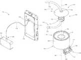
- FIG. 1shows a simplified representation of a tether system coupled to a mobile computing device
- FIG. 2shows a close up of a coupling apparatus of the tether system of FIG. 1 coupled to the mobile computing device;
- FIG. 3shows the coupling apparatus of FIG. 2 coupled to the mobile computing device, with a battery compartment lid removed from the mobile computing device;
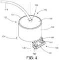
- FIG. 4shows a perspective view of a coupling apparatus for coupling a tether cord to a mobile computing device
- FIG. 5shows an exploded view of the coupling apparatus of FIG. 4 ;
- FIG. 6shows a perspective view of a cylindrical spacer and attachment element
- FIG. 7shows a top view of the cylindrical spacer with attachment element of FIG. 6 ;
- FIG. 8shows a bottom view of the cylindrical spacer with attachment element of FIG. 6 ;
- FIG. 9shows a side view of the cylindrical spacer with attachment element of FIG. 6 ;
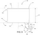
- FIG. 10illustrates a method of securing a mobile computing device to a base.
- embodiments of the present inventionrelate to tether systems, and, specifically, to a tether system for tethering a mobile computing device to a base.
- Mobile computing devicesare devices that use a computer processor to perform tasks.
- Mobile computing devicesinclude cellular telephones, cameras, tablets, scanners, and any other device that can be carried around and that has a computer processor. Because mobile computing devices are mobile, they can be lost or misplaced easily. This can be a problem when a mobile computing device is meant to stay in one location for multiple users to use. The mobile computing device can be accidentally, or purposely, carried away from the intended location, leaving subsequent users unable to use the mobile computing device.
- the disclosed tether systemtethers a mobile computing device to a base.
- the tether systemincludes a tether cord, the base, and a coupling apparatus.
- One end of the tether cordis coupled to the base.
- the basecan be coupled to an immovable structure, or the base itself can be immovable.
- the tether cordis coupled at the other end to the mobile computing device.
- the disclosed inventionuses the base, tether cord, and cap screw of a Sennco SystemsTM tether, with a novel cylindrical spacer specifically developed to couple the cap screw to a mobile computing device, creating a novel tether system that tethers a mobile computing device to a base while allowing the mobile computing device to be functional and securely coupled to the tether cord.
- FIG. 1shows a simplified diagram of a tether system 110 , with tether system 110 coupled to a mobile computing device 116 .
- Tether system 110includes a base 114 , a coupling apparatus 112 , and a tether cord 118 .
- Tether cord 118couples coupling apparatus 112 to base 114 .
- Tether cord 118can be any type of cord, string, or wire that can tether one object to another.
- coupling apparatus 112is coupled to mobile computing device 116 .
- tether cord 118couples mobile computing device 116 to base 114 .
- Tether cord 118has a tether cord first end 120 coupled to base 114 , and a tether cord second end 122 opposing tether cord first end 120 .
- Tether cord second end 122is coupled to coupling apparatus 112 .
- Tether cord 118couples coupling apparatus 112 and mobile computing device 116 to base 114 .
- Base 114can be secured to any device or structure it is desired to keep mobile computing device 116 near.
- Base 114can be coupled to a table, for example, or a wall, a charger for mobile computing device 116 , or any other device or structure that mobile computing device 116 is to be kept near.
- Base 114can be coupled to a table, for example, but not by way of limitation, where mobile computing device 116 is used by employees to perform tasks.
- base 114can be coupled to many different types and forms of structures or devices.
- Base 114is a rectangular box in this embodiment, but this is not meant to be limiting.
- Base 114can take many different forms other than that shown in the figures.
- base 114is a rectangular box with coupling holes so the box can be coupled to an object such as a table, a charger, a wall, etc.
- base 114is a different shape or form of a device to be coupled to another object.
- base 114is a fixed structure such as a table, a wall, a bookcase, a checkout station, or any other fixed structure that it is desired to tether mobile computing device 116 to.
- base 114is the stationary structure such as a table or other piece of furniture.
- base 114is a fixture in a retail store.
- Base 114can be any device, object, or structure that tether cord first end 120 can be coupled to.
- FIG. 2 through FIG. 9show details of coupling apparatus 112 .
- Coupling apparatus 112secures mobile computing device 116 to tether cord 118 .
- FIG. 2shows a close-up perspective view of coupling apparatus 112 coupled to mobile computing device 116 .
- FIG. 3shows a close-up perspective view of coupling apparatus 112 coupled to mobile computing device 116 , with a lid 174 of a battery compartment 170 of mobile computing device 116 removed so that coupling details are visible.
- FIG. 4shows a perspective view of coupling apparatus 112 .
- FIG. 5shows an exploded perspective view of coupling apparatus 112 .
- FIG. 6shows a top perspective view of a cylindrical spacer 130 of coupling apparatus 112 , and an attachment element 148 of coupling apparatus 112 .
- FIG. 7 through FIG. 9show top, bottom, and side views of cylindrical spacer 130 with attachment element 148 .
- Coupling apparatus 112in this embodiment, is coupled to a battery compartment 170 of mobile computing device 116 , as shown in FIG. 1 , FIG. 2 and FIG. 3 .
- Coupling apparatus 112includes a cylindrical spacer 130 , an attachment element 148 coupled to cylindrical spacer, and a cap screw 150 that screws into cylindrical spacer 130 .
- Tether cord second end 122is coupled to coupling apparatus 112 .
- Attachment element 148 of coupling apparatus 112is coupled to an inside surface 172 of battery compartment 170 , as shown in FIG. 3 , to couple coupling apparatus 112 to mobile computing device 116 .
- Screws 146extend through first and second screw holes 142 and 144 of an attachment plate 140 of coupling apparatus 112 ( FIG.
- screws 146are replaced with a different form of fastener or coupler. Any type of fastener or coupler can be used to secure attachment element 148 of coupling apparatus 112 to mobile computing device 116 .
- a neck 141 of attachment element 148extends through a seam 176 of mobile computing device 116 so that cylindrical spacer 130 and cap screw 150 are outside battery compartment 170 , while most of attachment element 148 and screws 146 are inside battery compartment 170 , see FIG. 2 and FIG. 3 .
- FIG. 4 and FIG. 5show a perspective view and an exploded perspective view, respectively, of coupling apparatus 112 , including cylindrical spacer 130 , attachment element 148 , and cap screw 150 .
- Cylindrical spacer 130takes the form of a thick cylindrical shaped spacer with a spacer hole 138 extending from a spacer top end 132 to a spacer bottom end 134 along a cylindrical axis 136 , see FIG. 5 through FIG. 9 .
- cylindrical spacer 130is formed of plastic, but this is not meant to be limiting.
- cylindrical spacer 130is formed of metal and spacer hole 138 is threaded.
- cylindrical spacer 130is formed of plastic, with cap screw 150 creating its own threads in spacer hole 138 when cap screw 150 is screwed into spacer hole 138 , see FIG. 5 .
- cylindrical spacer 130is formed of a self-tapping material such as plastic or wood. In some embodiments, cylindrical spacer 130 is formed of a material such as metal or ceramic that is threaded before cap screw 150 is screwed into cylindrical spacer 130 .
- Cylindrical spacer 130has a spacer top surface 133 ( FIG. 6 and FIG. 7 ) that is parallel to a spacer top surface plane 162 as shown in FIG. 9 . The top edge of spacer top end 132 lies in spacer top surface plane 162 .
- Cylindrical spacer 130has a spacer bottom surface 135 ( FIG. 8 ) that is parallel to a spacer bottom surface plane 164 as shown in 9 . The bottom edge of spacer bottom end 134 lies in spacer bottom surface plane 164 .
- Cap screw 150is a screw with a cap screw head 151 , a cap screw shaft 153 , a cap screw top end 152 , a cap screw bottom end 154 , and a cap screw hole 158 that extends along a cap screw longitudinal axis 156 from cap screw head 151 at cap screw top end 152 , through cap screw shaft 153 to cap screw bottom end 154 , see FIG. 5 .
- Cap screw shaft 153is threaded.
- Tether cord 118extends through cap screw hole 158 .
- An aglet 124is attached to tether cord second end 122 after tether cord 118 is extended through cap screw hole 158 , so that cap screw 150 cannot be removed from tether cord 118 at tether cord second end 122 , as shown in FIG. 5 .
- Aglet 124is larger than cap screw hole 158 , so aglet 124 does not pass through cap screw hole 158 .
- Cap screw 150is coupled to cylindrical spacer 130 by screwing cap screw 150 into spacer hole 138 of cylindrical spacer 130 so that cap screw head 151 is flush with cylindrical spacer top end 132 , and cap screw shaft 153 extends into, and is threaded into, spacer hole 138 , as shown in FIG. 4 and FIG. 5 .
- Cap screw longitudinal axis 156is colinear with cylindrical axis 136 when cap screw 150 is screwed into spacer hole 138 , see FIG. 5 .
- Cylindrical spacer 130is formed to have a depth 137 (see FIG. 9 ) greater than the length of cap screw shaft 153 so that cap screw shaft 153 does not protrude from cylindrical spacer bottom end 134 .
- Cylindrical spacer 130has an annular lip 131 at cylindrical spacer top end 132 so that cap screw head 151 is slightly inset into cylindrical spacer top end 132 , as shown in FIG. 4 and FIG. 5 .
- Cap screw head 151sets on cap screw top surface 133 .
- Attachment element 148is coupled to cylindrical spacer 130 and is used to couple cylindrical spacer 130 to mobile computing device 116 .
- attachment element 148 and cylindrical spacer 130are formed as a monolithic structure, usually molded in plastic, but not always.
- Attachment element 148includes attachment plate 140 and attachment neck 141 , as shown in FIG. 4 through FIG. 9 .
- Attachment neck 141couples attachment plate 140 to cylindrical spacer 130 .
- Attachment neck 141is a somewhat rectangular shaped element in this embodiment, but this is not meant to be limiting.
- Attachment neck 141is coupled to both cylindrical spacer 130 and attachment plate 140 .
- Attachment neck 141extends from cylindrical spacer 130 at spacer bottom end 134 .
- Attachment neck 141has a flat neck front surface 184 , see FIG. 9 , which lies in a neck plane 186 .
- Neck plane 186is tangential to cylindrical spacer 130 , see FIG. 7 . Having neck plane 184 tangential to cylindrical spacer 130 helps attachment element 148 fit through seam 176 of mobile computing device 116 .
- Neck plane 186 being tangential to cylindrical spacer 130means neck plane 186 is tangential to the outer surface of cylindrical spacer 130 .
- Attachment plate 140is a relatively rectangular shaped plate coupled to attachment neck 141 .
- Attachment plate 140is used to couple cylindrical spacer 130 of coupling apparatus 112 to mobile computing device 116 .
- Attachment plate 140has a flat attachment plate top surface 143 lying in an attachment plate plane 160 , see FIG. 9 .
- Attachment plate plane 160is parallel to spacer top surface plane 162 and spacer bottom surface plane 164 .
- Attachment plate plane 160is perpendicular to neck plane 186 , see FIG. 9 .
- Attachment plate 140is configured to be coupled to mobile computing device 116 .
- Attachment plate 140is configured to be coupled to a mobile computing device using two coupling holes 142 and 144 , in this embodiment.
- attachment plate 140is configured to couple to mobile computing device 116 using other coupling means or methods.
- Attachment plate 140has attachment plate top surface 143 , and an attachment plate bottom surface 145 ( FIG. 8 ).
- Attachment plate bottom surface 145is parallel to a spacer top surface 133 at spacer top end 132 , and a spacer bottom surface 135 of spacer bottom end 134 , as shown in FIG. 6 and FIG. 9 , and is also parallel to spacer top surface plane 162 and spacer bottom surface plane 164 .
- cylindrical spacer 130 and attachment element 148are a monolithic structure, but this is not meant to be limiting.
- attachment element 148is formed separate from cylindrical spacer 130 , and coupled to cylindrical spacer 130 .
- FIG. 10illustrates a method 200 of securing a mobile computing device to a base.
- Method 200includes an act 210 of coupling a tether cord first end of a tether cord to a base.
- the tether cordcan be any type of cord, string, or wire that can tether one object to another.
- the tether cordis retractable onto a reel in some embodiments.
- the baseis a rectangular box with coupling holes used to couple the base to an object such as a table, a charger, a wall, etc.
- the baseis a different shape or form of a device to be coupled to another object.
- the baseis a fixed structure such as a table, a wall, a bookcase, a checkout stand, or any other fixed structure that it is desired to tether a mobile computing device to.
- the basecan be any device, object, or structure that tether cord second end can be coupled to.
- the tether cord first endcan be coupled to the base using any coupling means and/or methods.
- Method 200also includes an act 220 of extending a tether cord second end through a cap screw hole in a cap screw.
- the cap screwis a screw with a cap screw head, a cap screw shaft, and a longitudinal axis.
- the cap screw holeextends longitudinally through the cap screw from a cap screw top end to a cap screw bottom end through the cap screw shaft.
- method 200includes drilling the cap screw hole in the cap screw longitudinally from the cap screw top end to the cap screw bottom end.
- Method 200also includes an act 230 of coupling an aglet to the tether cord second end to capture the cap screw onto the tether cord.
- the aglethas a size larger than the cap screw hole so that the aglet cannot pass through the cap screw hole.
- the agletis coupled to the tether cord second end after the second end is passed through the cap screw hole to prevent the cap screw from being removed from the tether cord at the tether cord second end.
- the basekeeps the cap screw from being removed from the tether cord at the tether cord first end.
- the aglet and the basecapture the cap screw on the tether cord.
- Method 200also includes an act 240 of screwing the cap screw into a cylindrical spacer.
- the cylindrical spacerhas an attachment element.
- the cylindrical spacerincludes a spacer top end, a spacer bottom end, a cylindrical axis and a spacer hole extending between the spacer top end and the spacer bottom end along the cylindrical axis.
- the attachment elementincludes an attachment plate and an attachment neck.
- the attachment platehas a flat attachment plate top surface lying in an attachment plate plane.
- the attachment plate planeis parallel to a spacer top surface plane and a spacer bottom surface plane.
- the attachment plateis configured to be coupled to a mobile computing device.
- the attachment neckis coupled to the attachment plate.
- the attachment neckis coupled to, and extends from, the cylindrical spacer at the spacer bottom end.
- the attachment neckcouples the attachment plate to the cylindrical spacer.
- Screwing the cap screw into the cylindrical spacercouples the cap screw and the tether to the cylindrical spacer.
- screwing the cap screw into the cylindrical spacerincludes screwing the cap screw into the spacer hole.
- the cap screwmakes its own threads in the spacer hole when the cap screw is screwed into the spacer hole.
- the spacer holeis threaded.
- the cap screwis coupled to the cylindrical spacer by means other than screwing the cap screw into the spacer hole.
- Method 200also includes an act 250 of coupling the attachment element to the mobile computing device.
- Coupling the attachment element to the mobile computing devicecouples the cylindrical spacer to the mobile computing device.
- the attachment elementcan be coupled to the mobile computing device in many ways.
- the attachment elementincludes the attachment plate, and coupling the attachment element to the mobile computing device includes coupling the attachment plate to the mobile computing device.
- coupling the attachment element to the mobile computing deviceincludes coupling the attachment plate to an inside surface of a battery compartment of the mobile computing device.
- the tether systemtethers a mobile computing device to a base.
- the tether systemallows the mobile computing device to be used by any number of individuals, but does not allow the mobile computing device to be moved further away from the base than the length of the tether. This keeps the mobile computing device from getting lost or stolen.
- the tether systemincludes a tether cord with a first end coupled to a base and a second end coupled to a coupling apparatus.
- the basecan be a fixed structure or can be coupled to a fixed structure at the location where the mobile computing device should be kept.
- the coupling apparatusis coupled to the mobile computing device.
- the coupling apparatusWith the coupling apparatus coupling one end of the tether cord to the mobile computing device, and the other end of the tether cord coupled to the base, the tether cord couples the mobile computing device to the base.
- the coupling apparatusincludes a cylindrical spacer with an attachment element, and a cap screw.
- the cap screwis coupled to the tether cord.
- the cap screwis screwed into a spacer hole in the cylindrical spacer to couple the cylindrical spacer and the cap screw.
- the attachment elementis coupled to the mobile computing device to couple the coupling apparatus to the mobile computing device.
Landscapes
- Engineering & Computer Science (AREA)
- Computer Hardware Design (AREA)
- Multimedia (AREA)
- Physics & Mathematics (AREA)
- General Physics & Mathematics (AREA)
- Telephone Set Structure (AREA)
Abstract
Description
Claims (15)
Priority Applications (1)
| Application Number | Priority Date | Filing Date | Title |
|---|---|---|---|
| US16/005,053US10619383B2 (en) | 2017-06-14 | 2018-06-11 | Tether system |
Applications Claiming Priority (2)
| Application Number | Priority Date | Filing Date | Title |
|---|---|---|---|
| US201762519460P | 2017-06-14 | 2017-06-14 | |
| US16/005,053US10619383B2 (en) | 2017-06-14 | 2018-06-11 | Tether system |
Publications (2)
| Publication Number | Publication Date |
|---|---|
| US20180363333A1 US20180363333A1 (en) | 2018-12-20 |
| US10619383B2true US10619383B2 (en) | 2020-04-14 |
Family
ID=64656623
Family Applications (1)
| Application Number | Title | Priority Date | Filing Date |
|---|---|---|---|
| US16/005,053Active2038-09-18US10619383B2 (en) | 2017-06-14 | 2018-06-11 | Tether system |
Country Status (1)
| Country | Link |
|---|---|
| US (1) | US10619383B2 (en) |
Cited By (1)
| Publication number | Priority date | Publication date | Assignee | Title |
|---|---|---|---|---|
| US11096503B2 (en)* | 2017-05-23 | 2021-08-24 | Eled Revolution Gmbh | Device for presenting small articles in sales shelf systems |
Citations (141)
| Publication number | Priority date | Publication date | Assignee | Title |
|---|---|---|---|---|
| US1681210A (en) | 1926-11-16 | 1928-08-21 | Reeve H Banks | Receptacle |
| US1715715A (en) | 1926-10-11 | 1929-06-04 | Julia G Mcvey | Attachment for tables |
| US1922935A (en) | 1932-03-31 | 1933-08-15 | Bois Hilyer A Du | Article supporting bracket |
| US1937994A (en) | 1932-01-06 | 1933-12-05 | Louis E Taylor | Card table |
| US2677520A (en) | 1949-03-21 | 1954-05-04 | John P Marcy | Combination glass holder and ash tray for tables and the like |
| US2891756A (en) | 1956-05-01 | 1959-06-23 | Florence M Packard | Auxiliary pressing attachment for ironing boards |
| US3076627A (en) | 1960-06-10 | 1963-02-05 | James W Huron | Vacuum sensitive electric control with mounting bracket |
| US4066231A (en)* | 1975-08-25 | 1978-01-03 | Bahner Randal E | Locking stand for small, portable devices |
| USD254051S (en) | 1978-11-16 | 1980-01-29 | Zaleski Joseph D | Snow guard |
| USD287817S (en) | 1985-08-15 | 1987-01-20 | Harris Hardware Sales Corp. | Frame mounting bracket for a swinging door |
| USD299809S (en) | 1985-07-12 | 1989-02-14 | Hagedorn Manfred R | Workbench support holder for automotive engine members or similar article |
| USD327214S (en) | 1988-08-30 | 1992-06-23 | El Barador Holding Pty. Ltd. | Bracket for anchoring posts, wall panels or the like |
| US5146205A (en)* | 1991-03-28 | 1992-09-08 | Protex International Corp. | Security and display system |
| USD349640S (en) | 1991-11-09 | 1994-08-16 | Commercial Brains Limited | Wall mountable support bracket |
| USD357400S (en) | 1993-08-03 | 1995-04-18 | Isaac Sachs | Connector element |
| US5454537A (en) | 1994-01-14 | 1995-10-03 | Cosco, Inc. | Cup holder |
| USD379144S (en) | 1995-11-16 | 1997-05-13 | Hunter Delphine G | Wall mount for television receiver |
| USD397606S (en) | 1997-09-09 | 1998-09-01 | Tameling John H | Wall mount bracket |
| USD408266S (en) | 1998-04-01 | 1999-04-20 | Santiago John V | Panel support |
| USD411098S (en) | 1997-12-10 | 1999-06-15 | Vogel's Holding B.V. | TV support |
| USD420278S (en) | 1998-02-04 | 2000-02-08 | Muskegon Tools, L.L.C. | Anti-rotation clip for nuts and bolts |
| USD427888S (en) | 1999-07-06 | 2000-07-11 | Midwest Motorcycle Supply Distributors Corp. | Mounting plate |
| USD432901S (en) | 1998-05-18 | 2000-10-31 | Unistrut Australia Pty Limited | Bracket |
| US6285758B1 (en) | 1999-08-30 | 2001-09-04 | Citech Co., Ltd. | Mobile phone holder |
| US20020033436A1 (en) | 2000-09-20 | 2002-03-21 | Acer Communications And Multimedia Inc. | Wall Mount unit for plasma display panel |
| US20020148935A1 (en) | 2001-03-28 | 2002-10-17 | Chambers Charles K. | Flexible mounting bracket |
| US6476717B2 (en)* | 2000-04-12 | 2002-11-05 | Cda Industries, Inc. | Tamper-proof display |
| US6511251B2 (en) | 1998-03-12 | 2003-01-28 | Martin Bowell | Table construction |
| US20030041631A1 (en) | 2001-09-06 | 2003-03-06 | Yin Memphis Zhihong | Portable computer security device |
| US6581421B2 (en)* | 2001-03-01 | 2003-06-24 | James Chmela | Security system |
| US6659382B2 (en)* | 2001-07-10 | 2003-12-09 | Vira Manufacturing, Inc. | Security device for display of hand held items |
| US6711921B1 (en) | 2002-09-30 | 2004-03-30 | Kuo-Tsung Yang | Locking device for a PDA and a charging base for the PDA |
| US6761579B2 (en)* | 1998-03-16 | 2004-07-13 | Telefonix, Inc. | Secure mounting assembly for a retail product display |
| US6769750B2 (en) | 2001-01-11 | 2004-08-03 | Kimball International, Inc. | Mechanical joint including angle bracket therefor |
| US6831560B2 (en)* | 2000-06-21 | 2004-12-14 | S.A.A.A. Systemes D'automatismes D'alarmes Automatiques | Security support for display articles |
| US6957978B2 (en) | 2003-07-31 | 2005-10-25 | Drew Zoller | Cord retainer |
| USD513969S1 (en) | 2004-02-10 | 2006-01-31 | Egs Electrical Group, Llc | Bracket |
| USD516023S1 (en) | 2004-12-21 | 2006-02-28 | Ckq Designs, Inc. | Holder/charging stand for a mobile phone or the like |
| USD516394S1 (en) | 2004-07-02 | 2006-03-07 | Goodly-Ch Enterprise Co., Ltd. | Hand tool |
| US7048246B2 (en)* | 2001-12-07 | 2006-05-23 | Se-Kure Controls, Inc. | Universal camera mount |
| US20060233601A1 (en) | 2005-04-15 | 2006-10-19 | Crain Stephen B | Coupler for a mount system |
| US7154039B1 (en) | 2005-12-05 | 2006-12-26 | Sennco Solutions, Inc. | System and method for securing and/or for aligning a device |
| US7162278B2 (en)* | 2004-02-27 | 2007-01-09 | Solectron Corporation | Secured wireless handsets |
| US20070007412A1 (en) | 2005-06-22 | 2007-01-11 | Chia-Ming Wang | Display panel mount bracket |
| USD537324S1 (en) | 2005-08-17 | 2007-02-27 | Avf Group Limited | Wall mount |
| USD542632S1 (en) | 2005-06-06 | 2007-05-15 | Richard Byrd Hill | Flashlight holder |
| USD546366S1 (en) | 2005-01-21 | 2007-07-10 | Csav, Inc. | Universal projector mount |
| US7264863B2 (en) | 2003-12-12 | 2007-09-04 | Illinois Tool Works Inc | Cabinet corner protector |
| US20070295870A1 (en) | 2006-06-12 | 2007-12-27 | Peterson Erik R | Wall mounted workstation |
| US20080079388A1 (en) | 2006-10-03 | 2008-04-03 | Visteon Global Technologies, Inc. | Wireless charging device |
| USD573008S1 (en) | 2006-09-08 | 2008-07-15 | Mark Sipe | Heavyweight wire support |
| US20080169393A1 (en) | 2007-01-15 | 2008-07-17 | Chen-Hsing Wang | Electronic device holder |
| USD574222S1 (en) | 2007-06-29 | 2008-08-05 | Metal Fabricating Corporation | End bracket for forkable base stand |
| USD576633S1 (en) | 2006-07-27 | 2008-09-09 | Omnimount Systems, Inc. | Extra-short cantilevered wall mount for a flat panel display |
| USD578816S1 (en) | 2008-04-01 | 2008-10-21 | Spectrum Diversified Designs, Inc. | Wall-mount magazine rack |
| US20080283694A1 (en) | 2007-05-14 | 2008-11-20 | Texas Instruments Incorporated | Tilting television wall mount |
| USD584553S1 (en) | 2008-04-22 | 2009-01-13 | Spectrum Diversified Designs, Inc. | Wall-mount file holder |
| US20090079566A1 (en)* | 2007-09-24 | 2009-03-26 | Invue Security Products, Inc. | Security device including sensor having an extension |
| US20090173868A1 (en)* | 2008-01-07 | 2009-07-09 | Invue Security Products, Inc. | Display stand including means for dispensing and collecting helical cable |
| USD606384S1 (en) | 2005-04-28 | 2009-12-22 | Antonic James P | Angle brace |
| USD608111S1 (en) | 2009-03-12 | 2010-01-19 | Erie Cotton Products Inc. | Machine-compressed rag dispensing rack |
| US20100039762A1 (en) | 2008-08-18 | 2010-02-18 | Eric Watson | Powered wall mount media display and data transfer system |
| US7724135B2 (en)* | 2007-03-29 | 2010-05-25 | Checkpoint Systems, Inc. | Coiled cable display device |
| US7724520B2 (en) | 2004-05-10 | 2010-05-25 | Peter Allen | Protruding lock for notebook computer or other personal electronic device |
| USD631735S1 (en) | 2010-08-18 | 2011-02-01 | Waverly Plastics Company, Inc. | Bracket for mounting a video monitor to a bag dispensing rack |
| US20110068919A1 (en)* | 2009-09-23 | 2011-03-24 | Checkpoint Systems, Inc. | Display assembly with cable stop |
| US20110157805A1 (en) | 2009-12-28 | 2011-06-30 | Hong Fu Jin Precision Industry (Shenzhen) Co., Ltd | Mounting apparatus for computer case |
| US7971845B2 (en)* | 2008-03-17 | 2011-07-05 | Compucage International Inc. | Security mount for displaying handheld device |
| US20110187531A1 (en)* | 2009-12-14 | 2011-08-04 | Apple Inc. | Systems and methods for securing handheld electronic devices |
| USD643708S1 (en) | 2010-12-02 | 2011-08-23 | Automatic Bar Controls, Inc. | Clip |
| US8103155B2 (en) | 2008-07-17 | 2012-01-24 | Jrd International Enterprises, Llc | Manually adjustable hair dryer mount for use with a hand-held hair dryer |
| US20120091086A1 (en) | 2010-10-18 | 2012-04-19 | Rubbermaid Incorporated | Rail storage system |
| USD660307S1 (en) | 2011-03-29 | 2012-05-22 | Ming-Hsien Huang | Display wall mount |
| US20120217371A1 (en)* | 2011-02-24 | 2012-08-30 | Invue Security Products Inc. | Merchandise display security tether including releasable adhesive |
| USD674637S1 (en) | 2011-12-07 | 2013-01-22 | Cardiac Science Corporation | Automated external defibrillator wall mount |
| US20130063267A1 (en)* | 2011-08-13 | 2013-03-14 | Geoff Yunker | Powered item attachment device |
| US8413943B1 (en)* | 2011-10-20 | 2013-04-09 | Aba Ufo International Corp. | Securing device for table device |
| US8418514B1 (en) | 2011-12-04 | 2013-04-16 | Ingamar Co. Ltd. | Tablet protector |
| US20130092805A1 (en) | 2011-10-14 | 2013-04-18 | Joe Funk | Tablet Mounting Arm Systems and Methods |
| US20130093386A1 (en) | 2011-10-18 | 2013-04-18 | Ming-Chiu TSAI | Slot-type induction charger |
| US20130153720A1 (en) | 2011-12-16 | 2013-06-20 | Halo Metrics Inc. | Apparatus and methods for securing products |
| US20130161054A1 (en) | 2011-12-21 | 2013-06-27 | Merchandising Technologies, Inc. | Security/Tether Cable |
| US8548536B1 (en) | 2012-04-17 | 2013-10-01 | Dennis M. Gunnip | Smart phone case with carry stand |
| US20130278050A1 (en) | 2010-10-08 | 2013-10-24 | Robert Bosch Gmbh | Holding Element and Control Module with a Holding Element of this Type |
| US20130320163A1 (en) | 2012-05-31 | 2013-12-05 | Fuson Limited | Adjustable Wall Mount for Flat Panel Television |
| US20140028243A1 (en) | 2011-12-22 | 2014-01-30 | Gary Rayner | Accessories for use with housing for an electronic device |
| USD700593S1 (en) | 2012-07-03 | 2014-03-04 | Loctek Visual Technology Corp. | TV wall mount |
| US20140059828A1 (en)* | 2012-08-30 | 2014-03-06 | Sennco Solutions Inc. | Apparatus, system and method for securing, attaching and/or detaching a device to a fixture |
| US20140091193A1 (en) | 2012-09-28 | 2014-04-03 | David Frederick Simon | Holder for books and electronic devices |
| US20140092531A1 (en)* | 2012-09-28 | 2014-04-03 | Target Brands, Inc. | Display system for mobile electronic devices and associated methods |
| US20140106608A1 (en)* | 2012-10-15 | 2014-04-17 | Apple Inc. | Methods And Systems For Displaying A Product |
| US8713858B1 (en) | 2011-12-22 | 2014-05-06 | Jason Sen Xie | Roof attachment flashing system |
| US8729852B2 (en) | 2010-06-03 | 2014-05-20 | Fu Da Tong Technology Co., Ltd. | Method for identification of a light inductive charger |
| USD705040S1 (en) | 2011-10-06 | 2014-05-20 | Walter M. Konrad | Rolling shutter exterior counter stop bracket |
| USD711736S1 (en) | 2013-01-30 | 2014-08-26 | Welch Allyn, Inc. | Basket |
| USD714616S1 (en) | 2012-09-27 | 2014-10-07 | Peak Innovations Inc. | Fascia mount bracket |
| US8869573B2 (en) | 2011-06-14 | 2014-10-28 | ACCO Brands Corporation | Protective case for physically securing a portable electronic device |
| US20150041622A1 (en) | 2012-04-16 | 2015-02-12 | Iordanka Koleva Mulhern | Rotating Mechanism for Computer or Similar Device |
| US20150070839A1 (en) | 2013-09-11 | 2015-03-12 | August A. JOHNSON | Multiple suction cup attachment platform: securing an electronic device on a vertical surface |
| USD726174S1 (en) | 2014-05-27 | 2015-04-07 | Vicki Wahlin | Smart phone case with lanyard attachment |
| USD729766S1 (en) | 2013-09-05 | 2015-05-19 | Vogel's Holding B.V. | Sound media wall mount |
| US20150144754A1 (en) | 2013-11-28 | 2015-05-28 | David ELHARAR | Apparatus for securing a mobile device to a steering wheel |
| USD734305S1 (en) | 2014-04-11 | 2015-07-14 | Innovelis, Inc. | Mount for electronic devices |
| US20150201113A1 (en) | 2013-02-13 | 2015-07-16 | Dennis Wood | Handheld Camera Balancing Apparatus |
| US20150208826A1 (en)* | 2014-01-24 | 2015-07-30 | Apple Inc. | Display systems and methods |
| US9097379B1 (en)* | 2010-10-25 | 2015-08-04 | Gomite, LLC | Articulating support for electronic devices |
| US9131195B2 (en) | 2010-11-23 | 2015-09-08 | Innovelis, Inc. | Mounting system for digital media players |
| US20150289396A1 (en) | 2014-04-02 | 2015-10-08 | Samsung Display Co., Ltd. | Display device |
| US9165174B2 (en) | 2013-10-14 | 2015-10-20 | Hand Held Products, Inc. | Indicia reader |
| US9179565B2 (en) | 2011-01-11 | 2015-11-03 | Sung-mok Cho | Portable electronic device holder |
| US20150329062A1 (en) | 2012-11-05 | 2015-11-19 | Kinetix Ag | Device for retaining flat, approximately rectangular appliances such as tablet computers or mobile telephones in the interior of a motor vehicle |
| USD744459S1 (en) | 2013-08-09 | 2015-12-01 | Pds Electronics, Inc. | Antenna feedpoint support bracket |
| USD744317S1 (en) | 2013-03-11 | 2015-12-01 | Sanmina Corporation | Structural member |
| US9272829B2 (en) | 2013-09-09 | 2016-03-01 | Lennox Industries Inc. | Stacking bracket |
| US20160176357A1 (en) | 2014-12-23 | 2016-06-23 | Reliant Worldwide Plastics, Llc | Thermoplastic composite retrofit panel assembly for personal entertainment device mount system |
| USD761236S1 (en) | 2014-04-04 | 2016-07-12 | Innovelis, Inc. | Mount for electronic devices |
| US20160204636A1 (en) | 2015-01-08 | 2016-07-14 | Hand Held Products, Inc. | System and method for charging a barcode scanner |
| USD766601S1 (en) | 2015-07-29 | 2016-09-20 | Neatfreak Group Inc. | Hanger |
| US9454917B1 (en) | 2015-09-30 | 2016-09-27 | Todd S. King | Display wall mount |
| USD771476S1 (en) | 2014-07-22 | 2016-11-15 | 3M Innovative Properties Company | Handle holder |
| USD774754S1 (en) | 2015-10-05 | 2016-12-27 | Ty-Flot, Inc. | Tool holder for T-shaped tools |
| USD774753S1 (en) | 2015-10-05 | 2016-12-27 | Ty-Flot, Inc. | Tool holder for T-shaped tools |
| USD776745S1 (en) | 2015-07-07 | 2017-01-17 | Gopro, Inc. | Long bite mount |
| USD776746S1 (en) | 2015-07-07 | 2017-01-17 | Gopro, Inc. | Short bite mount |
| US20170018156A1 (en)* | 2015-07-15 | 2017-01-19 | Kum Oh Electronics Co., Ltd. | Anti-theft apparatus for mobile device |
| US20170058572A1 (en) | 2014-08-26 | 2017-03-02 | Alexander Gad AVGANIM | Security device for portable objects |
| USD795266S1 (en) | 2016-07-21 | 2017-08-22 | Colebrook Bosson Saunders (Products) Limited | Tablet mount |
| US20170245663A1 (en)* | 2014-08-27 | 2017-08-31 | Invue Security Products Inc. | Systems and methods for locking a sensor to a base |
| USD796302S1 (en) | 2015-07-20 | 2017-09-05 | A&M Hardware Inc. | Bracket |
| US20170268716A1 (en) | 2014-12-12 | 2017-09-21 | Serge B. HOYDA | Mounting system for a camera |
| US20170339937A1 (en) | 2016-05-24 | 2017-11-30 | Nathanial Brent Erdmann | Fishing rod holder system |
| US20170347780A1 (en) | 2016-06-01 | 2017-12-07 | Wal-Mart Stores, Inc. | Mobile computing device holder |
| USD811199S1 (en) | 2016-07-28 | 2018-02-27 | Wal-Mart Stores, Inc. | Corner mount fixture |
| US9933107B2 (en) | 2015-09-30 | 2018-04-03 | Todd S. King | Display wall mount |
| USD821850S1 (en) | 2017-01-25 | 2018-07-03 | Club Pro Manufacturing Usa, Inc. | Bracket |
| US20180197389A1 (en) | 2015-07-08 | 2018-07-12 | Invue Security Products Inc. | Merchandise security systems |
| US10026281B2 (en)* | 2009-01-10 | 2018-07-17 | Mobile Tech, Inc. | Display for hand-held electronics |
| US20180229093A1 (en) | 2017-02-13 | 2018-08-16 | Mega Slam Hoops, Llc | Adjustable wall mount assembly for a basketball goal |
| US10084499B2 (en) | 2016-07-28 | 2018-09-25 | Walmart Apollo, Llc | Mobile computing device holder |
| USD829216S1 (en) | 2017-01-17 | 2018-09-25 | Swift Distribution, LLC | Laptop stand |
| USD831876S1 (en) | 2017-06-09 | 2018-10-23 | Sang Pil Moon | Wall-mount lighting fixture |
- 2018
- 2018-06-11USUS16/005,053patent/US10619383B2/enactiveActive
Patent Citations (145)
| Publication number | Priority date | Publication date | Assignee | Title |
|---|---|---|---|---|
| US1715715A (en) | 1926-10-11 | 1929-06-04 | Julia G Mcvey | Attachment for tables |
| US1681210A (en) | 1926-11-16 | 1928-08-21 | Reeve H Banks | Receptacle |
| US1937994A (en) | 1932-01-06 | 1933-12-05 | Louis E Taylor | Card table |
| US1922935A (en) | 1932-03-31 | 1933-08-15 | Bois Hilyer A Du | Article supporting bracket |
| US2677520A (en) | 1949-03-21 | 1954-05-04 | John P Marcy | Combination glass holder and ash tray for tables and the like |
| US2891756A (en) | 1956-05-01 | 1959-06-23 | Florence M Packard | Auxiliary pressing attachment for ironing boards |
| US3076627A (en) | 1960-06-10 | 1963-02-05 | James W Huron | Vacuum sensitive electric control with mounting bracket |
| US4066231A (en)* | 1975-08-25 | 1978-01-03 | Bahner Randal E | Locking stand for small, portable devices |
| USD254051S (en) | 1978-11-16 | 1980-01-29 | Zaleski Joseph D | Snow guard |
| USD299809S (en) | 1985-07-12 | 1989-02-14 | Hagedorn Manfred R | Workbench support holder for automotive engine members or similar article |
| USD287817S (en) | 1985-08-15 | 1987-01-20 | Harris Hardware Sales Corp. | Frame mounting bracket for a swinging door |
| USD327214S (en) | 1988-08-30 | 1992-06-23 | El Barador Holding Pty. Ltd. | Bracket for anchoring posts, wall panels or the like |
| US5146205A (en)* | 1991-03-28 | 1992-09-08 | Protex International Corp. | Security and display system |
| USD349640S (en) | 1991-11-09 | 1994-08-16 | Commercial Brains Limited | Wall mountable support bracket |
| USD357400S (en) | 1993-08-03 | 1995-04-18 | Isaac Sachs | Connector element |
| US5454537A (en) | 1994-01-14 | 1995-10-03 | Cosco, Inc. | Cup holder |
| USD379144S (en) | 1995-11-16 | 1997-05-13 | Hunter Delphine G | Wall mount for television receiver |
| USD397606S (en) | 1997-09-09 | 1998-09-01 | Tameling John H | Wall mount bracket |
| USD411098S (en) | 1997-12-10 | 1999-06-15 | Vogel's Holding B.V. | TV support |
| USD420278S (en) | 1998-02-04 | 2000-02-08 | Muskegon Tools, L.L.C. | Anti-rotation clip for nuts and bolts |
| US6511251B2 (en) | 1998-03-12 | 2003-01-28 | Martin Bowell | Table construction |
| US6761579B2 (en)* | 1998-03-16 | 2004-07-13 | Telefonix, Inc. | Secure mounting assembly for a retail product display |
| USD408266S (en) | 1998-04-01 | 1999-04-20 | Santiago John V | Panel support |
| USD432901S (en) | 1998-05-18 | 2000-10-31 | Unistrut Australia Pty Limited | Bracket |
| USD427888S (en) | 1999-07-06 | 2000-07-11 | Midwest Motorcycle Supply Distributors Corp. | Mounting plate |
| US6285758B1 (en) | 1999-08-30 | 2001-09-04 | Citech Co., Ltd. | Mobile phone holder |
| US6476717B2 (en)* | 2000-04-12 | 2002-11-05 | Cda Industries, Inc. | Tamper-proof display |
| US6831560B2 (en)* | 2000-06-21 | 2004-12-14 | S.A.A.A. Systemes D'automatismes D'alarmes Automatiques | Security support for display articles |
| US20020033436A1 (en) | 2000-09-20 | 2002-03-21 | Acer Communications And Multimedia Inc. | Wall Mount unit for plasma display panel |
| US6769750B2 (en) | 2001-01-11 | 2004-08-03 | Kimball International, Inc. | Mechanical joint including angle bracket therefor |
| US6581421B2 (en)* | 2001-03-01 | 2003-06-24 | James Chmela | Security system |
| US20020148935A1 (en) | 2001-03-28 | 2002-10-17 | Chambers Charles K. | Flexible mounting bracket |
| US6659382B2 (en)* | 2001-07-10 | 2003-12-09 | Vira Manufacturing, Inc. | Security device for display of hand held items |
| US20030041631A1 (en) | 2001-09-06 | 2003-03-06 | Yin Memphis Zhihong | Portable computer security device |
| US7048246B2 (en)* | 2001-12-07 | 2006-05-23 | Se-Kure Controls, Inc. | Universal camera mount |
| US6711921B1 (en) | 2002-09-30 | 2004-03-30 | Kuo-Tsung Yang | Locking device for a PDA and a charging base for the PDA |
| US6957978B2 (en) | 2003-07-31 | 2005-10-25 | Drew Zoller | Cord retainer |
| US7264863B2 (en) | 2003-12-12 | 2007-09-04 | Illinois Tool Works Inc | Cabinet corner protector |
| USD513969S1 (en) | 2004-02-10 | 2006-01-31 | Egs Electrical Group, Llc | Bracket |
| US7162278B2 (en)* | 2004-02-27 | 2007-01-09 | Solectron Corporation | Secured wireless handsets |
| US7724520B2 (en) | 2004-05-10 | 2010-05-25 | Peter Allen | Protruding lock for notebook computer or other personal electronic device |
| USD516394S1 (en) | 2004-07-02 | 2006-03-07 | Goodly-Ch Enterprise Co., Ltd. | Hand tool |
| USD516023S1 (en) | 2004-12-21 | 2006-02-28 | Ckq Designs, Inc. | Holder/charging stand for a mobile phone or the like |
| USD546366S1 (en) | 2005-01-21 | 2007-07-10 | Csav, Inc. | Universal projector mount |
| US20060233601A1 (en) | 2005-04-15 | 2006-10-19 | Crain Stephen B | Coupler for a mount system |
| USD606384S1 (en) | 2005-04-28 | 2009-12-22 | Antonic James P | Angle brace |
| USD542632S1 (en) | 2005-06-06 | 2007-05-15 | Richard Byrd Hill | Flashlight holder |
| US20070007412A1 (en) | 2005-06-22 | 2007-01-11 | Chia-Ming Wang | Display panel mount bracket |
| USD537324S1 (en) | 2005-08-17 | 2007-02-27 | Avf Group Limited | Wall mount |
| US7154039B1 (en) | 2005-12-05 | 2006-12-26 | Sennco Solutions, Inc. | System and method for securing and/or for aligning a device |
| US20070295870A1 (en) | 2006-06-12 | 2007-12-27 | Peterson Erik R | Wall mounted workstation |
| USD576633S1 (en) | 2006-07-27 | 2008-09-09 | Omnimount Systems, Inc. | Extra-short cantilevered wall mount for a flat panel display |
| USD573008S1 (en) | 2006-09-08 | 2008-07-15 | Mark Sipe | Heavyweight wire support |
| US20080079388A1 (en) | 2006-10-03 | 2008-04-03 | Visteon Global Technologies, Inc. | Wireless charging device |
| US20080169393A1 (en) | 2007-01-15 | 2008-07-17 | Chen-Hsing Wang | Electronic device holder |
| US7724135B2 (en)* | 2007-03-29 | 2010-05-25 | Checkpoint Systems, Inc. | Coiled cable display device |
| US20080283694A1 (en) | 2007-05-14 | 2008-11-20 | Texas Instruments Incorporated | Tilting television wall mount |
| USD574222S1 (en) | 2007-06-29 | 2008-08-05 | Metal Fabricating Corporation | End bracket for forkable base stand |
| US20090079566A1 (en)* | 2007-09-24 | 2009-03-26 | Invue Security Products, Inc. | Security device including sensor having an extension |
| US20090173868A1 (en)* | 2008-01-07 | 2009-07-09 | Invue Security Products, Inc. | Display stand including means for dispensing and collecting helical cable |
| US7971845B2 (en)* | 2008-03-17 | 2011-07-05 | Compucage International Inc. | Security mount for displaying handheld device |
| USD578816S1 (en) | 2008-04-01 | 2008-10-21 | Spectrum Diversified Designs, Inc. | Wall-mount magazine rack |
| USD584553S1 (en) | 2008-04-22 | 2009-01-13 | Spectrum Diversified Designs, Inc. | Wall-mount file holder |
| US8103155B2 (en) | 2008-07-17 | 2012-01-24 | Jrd International Enterprises, Llc | Manually adjustable hair dryer mount for use with a hand-held hair dryer |
| US20100039762A1 (en) | 2008-08-18 | 2010-02-18 | Eric Watson | Powered wall mount media display and data transfer system |
| US10026281B2 (en)* | 2009-01-10 | 2018-07-17 | Mobile Tech, Inc. | Display for hand-held electronics |
| USD608111S1 (en) | 2009-03-12 | 2010-01-19 | Erie Cotton Products Inc. | Machine-compressed rag dispensing rack |
| US20110068919A1 (en)* | 2009-09-23 | 2011-03-24 | Checkpoint Systems, Inc. | Display assembly with cable stop |
| US20110187531A1 (en)* | 2009-12-14 | 2011-08-04 | Apple Inc. | Systems and methods for securing handheld electronic devices |
| US20110157805A1 (en) | 2009-12-28 | 2011-06-30 | Hong Fu Jin Precision Industry (Shenzhen) Co., Ltd | Mounting apparatus for computer case |
| US8077449B2 (en) | 2009-12-28 | 2011-12-13 | Hong Fu Jin Precision Industry (Shenzhen) Co., Ltd. | Mounting apparatus for computer case |
| US8729852B2 (en) | 2010-06-03 | 2014-05-20 | Fu Da Tong Technology Co., Ltd. | Method for identification of a light inductive charger |
| USD631735S1 (en) | 2010-08-18 | 2011-02-01 | Waverly Plastics Company, Inc. | Bracket for mounting a video monitor to a bag dispensing rack |
| US20130278050A1 (en) | 2010-10-08 | 2013-10-24 | Robert Bosch Gmbh | Holding Element and Control Module with a Holding Element of this Type |
| US9115846B2 (en) | 2010-10-08 | 2015-08-25 | Robert Bosch Gmbh | Holding element and control module with a holding element of this type |
| US20120091086A1 (en) | 2010-10-18 | 2012-04-19 | Rubbermaid Incorporated | Rail storage system |
| US9097379B1 (en)* | 2010-10-25 | 2015-08-04 | Gomite, LLC | Articulating support for electronic devices |
| US9131195B2 (en) | 2010-11-23 | 2015-09-08 | Innovelis, Inc. | Mounting system for digital media players |
| USD643708S1 (en) | 2010-12-02 | 2011-08-23 | Automatic Bar Controls, Inc. | Clip |
| US9179565B2 (en) | 2011-01-11 | 2015-11-03 | Sung-mok Cho | Portable electronic device holder |
| US20120217371A1 (en)* | 2011-02-24 | 2012-08-30 | Invue Security Products Inc. | Merchandise display security tether including releasable adhesive |
| USD660307S1 (en) | 2011-03-29 | 2012-05-22 | Ming-Hsien Huang | Display wall mount |
| US8869573B2 (en) | 2011-06-14 | 2014-10-28 | ACCO Brands Corporation | Protective case for physically securing a portable electronic device |
| US20130063267A1 (en)* | 2011-08-13 | 2013-03-14 | Geoff Yunker | Powered item attachment device |
| USD705040S1 (en) | 2011-10-06 | 2014-05-20 | Walter M. Konrad | Rolling shutter exterior counter stop bracket |
| US20130092805A1 (en) | 2011-10-14 | 2013-04-18 | Joe Funk | Tablet Mounting Arm Systems and Methods |
| US20130093386A1 (en) | 2011-10-18 | 2013-04-18 | Ming-Chiu TSAI | Slot-type induction charger |
| US8413943B1 (en)* | 2011-10-20 | 2013-04-09 | Aba Ufo International Corp. | Securing device for table device |
| US8418514B1 (en) | 2011-12-04 | 2013-04-16 | Ingamar Co. Ltd. | Tablet protector |
| USD674637S1 (en) | 2011-12-07 | 2013-01-22 | Cardiac Science Corporation | Automated external defibrillator wall mount |
| US9022337B2 (en) | 2011-12-16 | 2015-05-05 | Halo Metrics Inc. | Apparatus and methods for securing products |
| US20130153720A1 (en) | 2011-12-16 | 2013-06-20 | Halo Metrics Inc. | Apparatus and methods for securing products |
| US20130161054A1 (en) | 2011-12-21 | 2013-06-27 | Merchandising Technologies, Inc. | Security/Tether Cable |
| US8713858B1 (en) | 2011-12-22 | 2014-05-06 | Jason Sen Xie | Roof attachment flashing system |
| US20140028243A1 (en) | 2011-12-22 | 2014-01-30 | Gary Rayner | Accessories for use with housing for an electronic device |
| US20150041622A1 (en) | 2012-04-16 | 2015-02-12 | Iordanka Koleva Mulhern | Rotating Mechanism for Computer or Similar Device |
| US8548536B1 (en) | 2012-04-17 | 2013-10-01 | Dennis M. Gunnip | Smart phone case with carry stand |
| US20130320163A1 (en) | 2012-05-31 | 2013-12-05 | Fuson Limited | Adjustable Wall Mount for Flat Panel Television |
| USD700593S1 (en) | 2012-07-03 | 2014-03-04 | Loctek Visual Technology Corp. | TV wall mount |
| US20140059828A1 (en)* | 2012-08-30 | 2014-03-06 | Sennco Solutions Inc. | Apparatus, system and method for securing, attaching and/or detaching a device to a fixture |
| USD714616S1 (en) | 2012-09-27 | 2014-10-07 | Peak Innovations Inc. | Fascia mount bracket |
| US20140092531A1 (en)* | 2012-09-28 | 2014-04-03 | Target Brands, Inc. | Display system for mobile electronic devices and associated methods |
| US20140091193A1 (en) | 2012-09-28 | 2014-04-03 | David Frederick Simon | Holder for books and electronic devices |
| US20140106608A1 (en)* | 2012-10-15 | 2014-04-17 | Apple Inc. | Methods And Systems For Displaying A Product |
| US20150329062A1 (en) | 2012-11-05 | 2015-11-19 | Kinetix Ag | Device for retaining flat, approximately rectangular appliances such as tablet computers or mobile telephones in the interior of a motor vehicle |
| USD711736S1 (en) | 2013-01-30 | 2014-08-26 | Welch Allyn, Inc. | Basket |
| US20150201113A1 (en) | 2013-02-13 | 2015-07-16 | Dennis Wood | Handheld Camera Balancing Apparatus |
| USD744317S1 (en) | 2013-03-11 | 2015-12-01 | Sanmina Corporation | Structural member |
| USD744459S1 (en) | 2013-08-09 | 2015-12-01 | Pds Electronics, Inc. | Antenna feedpoint support bracket |
| USD729766S1 (en) | 2013-09-05 | 2015-05-19 | Vogel's Holding B.V. | Sound media wall mount |
| US9272829B2 (en) | 2013-09-09 | 2016-03-01 | Lennox Industries Inc. | Stacking bracket |
| US9128668B2 (en) | 2013-09-11 | 2015-09-08 | August A. JOHNSON | Multiple suction cup attachment platform: securing an electronic device on a vertical surface |
| US20150070839A1 (en) | 2013-09-11 | 2015-03-12 | August A. JOHNSON | Multiple suction cup attachment platform: securing an electronic device on a vertical surface |
| US9165174B2 (en) | 2013-10-14 | 2015-10-20 | Hand Held Products, Inc. | Indicia reader |
| US20150144754A1 (en) | 2013-11-28 | 2015-05-28 | David ELHARAR | Apparatus for securing a mobile device to a steering wheel |
| US20150208826A1 (en)* | 2014-01-24 | 2015-07-30 | Apple Inc. | Display systems and methods |
| US20150289396A1 (en) | 2014-04-02 | 2015-10-08 | Samsung Display Co., Ltd. | Display device |
| USD761236S1 (en) | 2014-04-04 | 2016-07-12 | Innovelis, Inc. | Mount for electronic devices |
| USD734305S1 (en) | 2014-04-11 | 2015-07-14 | Innovelis, Inc. | Mount for electronic devices |
| USD726174S1 (en) | 2014-05-27 | 2015-04-07 | Vicki Wahlin | Smart phone case with lanyard attachment |
| USD771476S1 (en) | 2014-07-22 | 2016-11-15 | 3M Innovative Properties Company | Handle holder |
| US20170058572A1 (en) | 2014-08-26 | 2017-03-02 | Alexander Gad AVGANIM | Security device for portable objects |
| US20170245663A1 (en)* | 2014-08-27 | 2017-08-31 | Invue Security Products Inc. | Systems and methods for locking a sensor to a base |
| US20170268716A1 (en) | 2014-12-12 | 2017-09-21 | Serge B. HOYDA | Mounting system for a camera |
| US20160176357A1 (en) | 2014-12-23 | 2016-06-23 | Reliant Worldwide Plastics, Llc | Thermoplastic composite retrofit panel assembly for personal entertainment device mount system |
| US20160204636A1 (en) | 2015-01-08 | 2016-07-14 | Hand Held Products, Inc. | System and method for charging a barcode scanner |
| USD776745S1 (en) | 2015-07-07 | 2017-01-17 | Gopro, Inc. | Long bite mount |
| USD776746S1 (en) | 2015-07-07 | 2017-01-17 | Gopro, Inc. | Short bite mount |
| US20180197389A1 (en) | 2015-07-08 | 2018-07-12 | Invue Security Products Inc. | Merchandise security systems |
| US20170018156A1 (en)* | 2015-07-15 | 2017-01-19 | Kum Oh Electronics Co., Ltd. | Anti-theft apparatus for mobile device |
| USD796302S1 (en) | 2015-07-20 | 2017-09-05 | A&M Hardware Inc. | Bracket |
| USD766601S1 (en) | 2015-07-29 | 2016-09-20 | Neatfreak Group Inc. | Hanger |
| US9933107B2 (en) | 2015-09-30 | 2018-04-03 | Todd S. King | Display wall mount |
| US9454917B1 (en) | 2015-09-30 | 2016-09-27 | Todd S. King | Display wall mount |
| USD774754S1 (en) | 2015-10-05 | 2016-12-27 | Ty-Flot, Inc. | Tool holder for T-shaped tools |
| USD774753S1 (en) | 2015-10-05 | 2016-12-27 | Ty-Flot, Inc. | Tool holder for T-shaped tools |
| US20170339937A1 (en) | 2016-05-24 | 2017-11-30 | Nathanial Brent Erdmann | Fishing rod holder system |
| US20170347780A1 (en) | 2016-06-01 | 2017-12-07 | Wal-Mart Stores, Inc. | Mobile computing device holder |
| USD795266S1 (en) | 2016-07-21 | 2017-08-22 | Colebrook Bosson Saunders (Products) Limited | Tablet mount |
| USD811199S1 (en) | 2016-07-28 | 2018-02-27 | Wal-Mart Stores, Inc. | Corner mount fixture |
| US10084499B2 (en) | 2016-07-28 | 2018-09-25 | Walmart Apollo, Llc | Mobile computing device holder |
| USD829216S1 (en) | 2017-01-17 | 2018-09-25 | Swift Distribution, LLC | Laptop stand |
| USD821850S1 (en) | 2017-01-25 | 2018-07-03 | Club Pro Manufacturing Usa, Inc. | Bracket |
| US20180229093A1 (en) | 2017-02-13 | 2018-08-16 | Mega Slam Hoops, Llc | Adjustable wall mount assembly for a basketball goal |
| USD831876S1 (en) | 2017-06-09 | 2018-10-23 | Sang Pil Moon | Wall-mount lighting fixture |
Non-Patent Citations (38)
| Title |
|---|
| "Code Reader 2500 CR2500 512G_01 Barcode Scanner w/Charger + Handle," Ebay.com, accessed on Jun. 15, 2017; 4 pages. |
| "Freedom Micro™," MobileTechnic.com, Mobile Technologies Inc., accessed on Apr. 24, 2017; 5 pages. |
| "Inon Double Hole Rubber bushing (for fiber optic cable)," Backscatter.com, accessed on Apr. 25, 2017I 2 pages. |
| "Recent RTF News and Updates: Open display, retail smartphone security devices now produced in Brazil," RTFGlobal.com, accessed on Apr. 24, 2017; 3 pages. |
| "Wireless Laser Barcode Scanner Label Reader with Charger Base Handheld Barcode Scanning for Supermarket Shop," DHGate.com, accessed on Jun. 15, 2017; 3 pages. |
| 10 Units crank angle bracket plastic frame angular DIY model accessories, AliExpress.com, first accessed May 27, 2016; 12 pages. |
| AnchorPad, "vRT Medium Retractable Tether with 29.5 Inch Cable for iPods & iPhones", Amazon.com, first accessed on May 27, 2016; 5 pages. |
| Cell Phone Wall Charger Adapter Charging Holder Hanging Support (2-Piece), first accessed on May 28, 2016; 2 pages. |
| Corner Brace 2-1/2 x 2-1/2 x 3/4 in White Plastic, OvisOnline.com, Ovis division of WIM Corp, accessed on Jun. 29, 2016; 4 pages. |
| Corner Bracket Levelers, 4 pack, Woodcraft.com, Woodcraft Supply LLC, accessed on Jun. 29, 2016; 2 pages. |
| Dardytrading, "Anti-lost Pull Box Anti Theft Recoiler Cable Retracting Display Cable Retracting Security Cable Merchandise Security Tether Security Recoiler," DHGate.com, accessed on Apr. 24, 2017; 11 pages. |
| Generic, "Television/Air Conditioner Remote Control Holder Wall Mount-Storage Box", Amazon.com, first accessed on May 27, 2016; 6 pages. |
| Glide Brackets and Systems, USFutaba.com, U.S. Futuba, Inc., accessed on Jun. 29, 2016; 2 pages. |
| HighPoint Corner Bracket Levelers 4-piece, Woodcraft.com, Woodcraft Supply LLC, accessed on Jun. 29, 2016; 2 pages. |
| Maurerpe, "Wall Mount for Vtech 6419 Cordless Phone", MakerBot Thingiverse, Apr. 20, 2013; 6 pages. |
| Mid-Century Meets Modern: Gidloof Originals—Tiagosen, Design-Milk.com, Mar. 4, 2013; 14 pages. |
| Non-Final Office Action for U.S. Appl. No. 15/657,693, dated Mar. 22, 2018; 7 pages. |
| Non-Final Office Action in U.S. Appl. No. 15/602,227 dated Aug. 27, 2018. |
| Notice of Allowance in U.S. Appl. No. 15/602,227 dated Jan. 11, 2019; 11 pages. |
| Notice of Allowance in U.S. Appl. No. 15/657,693 dated Jul. 6, 2018; 5 pages. |
| Notice of Allowance in U.S. Appl. No. 29/566,595, dated Jun. 30, 2017; 6 pages. |
| Notice of Allowance in U.S. Appl. No. 29/566,596 dated Jan. 24, 2019; 14 pages. |
| Notice of Allowance in U.S. Appl. No. 29/572,493, dated Dec. 27, 2017; 8 pages. |
| Pack of 10 Heavy Duty Corner Braces 50mm Angle Bracket F Plate NEW, Ebay.com, White Hinge Ltd, accessed on Jun. 29, 2016; 4 pages. |
| Plastic Sensor 2.0 Wall Mount Stand Holder for Zbox One Kinect 2.0—Black, Deal Extreme, DX.com, first accessed on May 28, 2016; 4 pages. |
| Product Photos, DeckMaster.com, first accessed May 27, 2016; 10 pages. |
| Profis, Sharon, "How to mount your smartphone on a tripod (DIY)", CNET.com, Mar. 26, 2014; 5 pages. |
| Redlinecarparts, "BMW 320D 99-06 Front Wishbone Bush with Bracket Lh O," Ebay.com, accessed on Apr. 24, 2017; 5 pages. |
| Repe, "High Rated Brush Coating Finish Plastic Composite Railing Metal L Shape WPC Clip Accessory", TimberCompositeDecking.com, first accessed May 27, 2016; 2 pages. |
| Screw-on Corner Braces, 4-Pack, Rockler.com, Rockler Woodworking and Hardware, accessed on Jun. 29, 2016; 6 pages. |
| Sea-Dog, "Sea-Dog Removable Table Brackets—Stainless Steel", DownwindMarine.com, first accessed on May 28, 2016; 1 page. |
| Series Accessories: Developed for your Dynaudio loudspeakers, Dynaudio.com, first accessed on May 28, 2016; 6 pages. |
| Tram-browning, "L-Bracket 1255 3/4 Hole Stainless Steel NMO 3/4 Hole Mount L Bracket Mobile Antennas Motorola Kenwood Vertex HYT for UHF VHF Coam NMO Mount Cable Mobile Antennas Car Truck Hood install by tram-browning", Amazon.com, first accessed on May 27, 2016; 5 pages. |
| vGaurd, "vG-SDM003 Square Security Display Magnetic Mounting Holder for Cell Phone", WelGaurd.com, first accessed on May 27, 2016; 7 pages. |
| vGuard, "vG-SDM001 Small Oval Security Display Magnet Mount + Pull Box tehter", AliExpress.com, first accessed on May 27, 2016; 2 pages. |
| vGuard, "vG-SDM004 Small Round Security Display Magnet Mount + Pull Box", WelGaurd.com, first accessed on May 27, 2016; 6 pages. |
| Video Mount Products Vented Wall Mount Shelf, CableOrganizer.com, first accessed on May 28, 2016; 3 pages. |
| ZAZZ, "ZAZZ Wall Mount for iPad/Kindle and Tablets (Black)", Amazon.com, first accessed on May 27, 2016; 5 pages. |
Cited By (1)
| Publication number | Priority date | Publication date | Assignee | Title |
|---|---|---|---|---|
| US11096503B2 (en)* | 2017-05-23 | 2021-08-24 | Eled Revolution Gmbh | Device for presenting small articles in sales shelf systems |
Also Published As
| Publication number | Publication date |
|---|---|
| US20180363333A1 (en) | 2018-12-20 |
Similar Documents
| Publication | Publication Date | Title |
|---|---|---|
| KR101608754B1 (en) | a accessary for cellular phone | |
| US10484522B1 (en) | Utility case for electronic devices | |
| US8934237B2 (en) | Portable electronic device | |
| US6486397B2 (en) | Apparatus for receiving universal serial bus cables | |
| US20150115125A1 (en) | Flatbase bracket | |
| US20130284614A1 (en) | Holder for portable electronic device | |
| US9448585B2 (en) | Clamping structure, electronic device and clamping component | |
| USD928531S1 (en) | Interconnecting panel element | |
| US20150116286A1 (en) | Tag and stabilizer for stylus attachment | |
| US10619383B2 (en) | Tether system | |
| US10125542B1 (en) | Magnetic organizing device | |
| US20120120299A1 (en) | Portable electronic device with adjustable camera | |
| US8918961B2 (en) | Electronic device with hinge structure | |
| US8491245B2 (en) | Positioning assembly | |
| US20140054194A1 (en) | Packaging assembly | |
| US8422208B2 (en) | Stand fixing mechanism and electronic device using the same | |
| US10136525B2 (en) | Display device | |
| KR200470736Y1 (en) | Tablet pc case | |
| US20170206810A1 (en) | Personal Signage Assembly | |
| US20140146452A1 (en) | Electronic device and housing | |
| US20140085785A1 (en) | Electronic device with rubber pads | |
| WO2021051385A1 (en) | Protective case for electronic product | |
| US7724506B2 (en) | Electronic device | |
| US11085575B2 (en) | Bracket assembly and display device comprising the same | |
| US8313273B2 (en) | Hook assembly |
Legal Events
| Date | Code | Title | Description |
|---|---|---|---|
| AS | Assignment | Owner name:WAL-MART STORES, INC., ARKANSAS Free format text:ASSIGNMENT OF ASSIGNORS INTEREST;ASSIGNOR:BACALLAO, YURGIS MAURO;REEL/FRAME:046045/0285 Effective date:20170614 Owner name:WALMART APOLLO, LLC, ARKANSAS Free format text:ASSIGNMENT OF ASSIGNORS INTEREST;ASSIGNOR:WAL-MART STORES, INC.;REEL/FRAME:047223/0839 Effective date:20180226 | |
| FEPP | Fee payment procedure | Free format text:ENTITY STATUS SET TO UNDISCOUNTED (ORIGINAL EVENT CODE: BIG.); ENTITY STATUS OF PATENT OWNER: LARGE ENTITY | |
| STPP | Information on status: patent application and granting procedure in general | Free format text:DOCKETED NEW CASE - READY FOR EXAMINATION | |
| STPP | Information on status: patent application and granting procedure in general | Free format text:NON FINAL ACTION MAILED | |
| STPP | Information on status: patent application and granting procedure in general | Free format text:NOTICE OF ALLOWANCE MAILED -- APPLICATION RECEIVED IN OFFICE OF PUBLICATIONS | |
| STCF | Information on status: patent grant | Free format text:PATENTED CASE | |
| MAFP | Maintenance fee payment | Free format text:PAYMENT OF MAINTENANCE FEE, 4TH YEAR, LARGE ENTITY (ORIGINAL EVENT CODE: M1551); ENTITY STATUS OF PATENT OWNER: LARGE ENTITY Year of fee payment:4 |