US10617603B2 - Sterile solutions product bag - Google Patents
Sterile solutions product bagDownload PDFInfo
- Publication number
- US10617603B2 US10617603B2US16/070,009US201716070009AUS10617603B2US 10617603 B2US10617603 B2US 10617603B2US 201716070009 AUS201716070009 AUS 201716070009AUS 10617603 B2US10617603 B2US 10617603B2
- Authority
- US
- United States
- Prior art keywords
- filter
- stem
- product bag
- sterile solution
- solution product
- Prior art date
- Legal status (The legal status is an assumption and is not a legal conclusion. Google has not performed a legal analysis and makes no representation as to the accuracy of the status listed.)
- Active
Links
Images


Classifications
- A—HUMAN NECESSITIES
- A61—MEDICAL OR VETERINARY SCIENCE; HYGIENE
- A61J—CONTAINERS SPECIALLY ADAPTED FOR MEDICAL OR PHARMACEUTICAL PURPOSES; DEVICES OR METHODS SPECIALLY ADAPTED FOR BRINGING PHARMACEUTICAL PRODUCTS INTO PARTICULAR PHYSICAL OR ADMINISTERING FORMS; DEVICES FOR ADMINISTERING FOOD OR MEDICINES ORALLY; BABY COMFORTERS; DEVICES FOR RECEIVING SPITTLE
- A61J1/00—Containers specially adapted for medical or pharmaceutical purposes
- A61J1/14—Details; Accessories therefor
- A61J1/1443—Containers with means for dispensing liquid medicaments in a filtered or sterile way, e.g. with bacterial filters
- A61J1/1456—Containers with means for dispensing liquid medicaments in a filtered or sterile way, e.g. with bacterial filters using liquid filters
- A—HUMAN NECESSITIES
- A61—MEDICAL OR VETERINARY SCIENCE; HYGIENE
- A61J—CONTAINERS SPECIALLY ADAPTED FOR MEDICAL OR PHARMACEUTICAL PURPOSES; DEVICES OR METHODS SPECIALLY ADAPTED FOR BRINGING PHARMACEUTICAL PRODUCTS INTO PARTICULAR PHYSICAL OR ADMINISTERING FORMS; DEVICES FOR ADMINISTERING FOOD OR MEDICINES ORALLY; BABY COMFORTERS; DEVICES FOR RECEIVING SPITTLE
- A61J1/00—Containers specially adapted for medical or pharmaceutical purposes
- A61J1/14—Details; Accessories therefor
- A—HUMAN NECESSITIES
- A61—MEDICAL OR VETERINARY SCIENCE; HYGIENE
- A61J—CONTAINERS SPECIALLY ADAPTED FOR MEDICAL OR PHARMACEUTICAL PURPOSES; DEVICES OR METHODS SPECIALLY ADAPTED FOR BRINGING PHARMACEUTICAL PRODUCTS INTO PARTICULAR PHYSICAL OR ADMINISTERING FORMS; DEVICES FOR ADMINISTERING FOOD OR MEDICINES ORALLY; BABY COMFORTERS; DEVICES FOR RECEIVING SPITTLE
- A61J1/00—Containers specially adapted for medical or pharmaceutical purposes
- A61J1/05—Containers specially adapted for medical or pharmaceutical purposes for collecting, storing or administering blood, plasma or medical fluids ; Infusion or perfusion containers
- A61J1/10—Bag-type containers
- A—HUMAN NECESSITIES
- A61—MEDICAL OR VETERINARY SCIENCE; HYGIENE
- A61J—CONTAINERS SPECIALLY ADAPTED FOR MEDICAL OR PHARMACEUTICAL PURPOSES; DEVICES OR METHODS SPECIALLY ADAPTED FOR BRINGING PHARMACEUTICAL PRODUCTS INTO PARTICULAR PHYSICAL OR ADMINISTERING FORMS; DEVICES FOR ADMINISTERING FOOD OR MEDICINES ORALLY; BABY COMFORTERS; DEVICES FOR RECEIVING SPITTLE
- A61J1/00—Containers specially adapted for medical or pharmaceutical purposes
- A61J1/14—Details; Accessories therefor
- A61J1/1406—Septums, pierceable membranes
- A—HUMAN NECESSITIES
- A61—MEDICAL OR VETERINARY SCIENCE; HYGIENE
- A61J—CONTAINERS SPECIALLY ADAPTED FOR MEDICAL OR PHARMACEUTICAL PURPOSES; DEVICES OR METHODS SPECIALLY ADAPTED FOR BRINGING PHARMACEUTICAL PRODUCTS INTO PARTICULAR PHYSICAL OR ADMINISTERING FORMS; DEVICES FOR ADMINISTERING FOOD OR MEDICINES ORALLY; BABY COMFORTERS; DEVICES FOR RECEIVING SPITTLE
- A61J1/00—Containers specially adapted for medical or pharmaceutical purposes
- A61J1/14—Details; Accessories therefor
- A61J1/1412—Containers with closing means, e.g. caps
- A—HUMAN NECESSITIES
- A61—MEDICAL OR VETERINARY SCIENCE; HYGIENE
- A61J—CONTAINERS SPECIALLY ADAPTED FOR MEDICAL OR PHARMACEUTICAL PURPOSES; DEVICES OR METHODS SPECIALLY ADAPTED FOR BRINGING PHARMACEUTICAL PRODUCTS INTO PARTICULAR PHYSICAL OR ADMINISTERING FORMS; DEVICES FOR ADMINISTERING FOOD OR MEDICINES ORALLY; BABY COMFORTERS; DEVICES FOR RECEIVING SPITTLE
- A61J1/00—Containers specially adapted for medical or pharmaceutical purposes
- A61J1/14—Details; Accessories therefor
- A61J1/1475—Inlet or outlet ports
- A—HUMAN NECESSITIES
- A61—MEDICAL OR VETERINARY SCIENCE; HYGIENE
- A61M—DEVICES FOR INTRODUCING MEDIA INTO, OR ONTO, THE BODY; DEVICES FOR TRANSDUCING BODY MEDIA OR FOR TAKING MEDIA FROM THE BODY; DEVICES FOR PRODUCING OR ENDING SLEEP OR STUPOR
- A61M1/00—Suction or pumping devices for medical purposes; Devices for carrying-off, for treatment of, or for carrying-over, body-liquids; Drainage systems
- A61M1/02—Blood transfusion apparatus
- A61M1/0209—Multiple bag systems for separating or storing blood components
- A61M1/0218—Multiple bag systems for separating or storing blood components with filters
- A—HUMAN NECESSITIES
- A61—MEDICAL OR VETERINARY SCIENCE; HYGIENE
- A61M—DEVICES FOR INTRODUCING MEDIA INTO, OR ONTO, THE BODY; DEVICES FOR TRANSDUCING BODY MEDIA OR FOR TAKING MEDIA FROM THE BODY; DEVICES FOR PRODUCING OR ENDING SLEEP OR STUPOR
- A61M1/00—Suction or pumping devices for medical purposes; Devices for carrying-off, for treatment of, or for carrying-over, body-liquids; Drainage systems
- A61M1/14—Dialysis systems; Artificial kidneys; Blood oxygenators ; Reciprocating systems for treatment of body fluids, e.g. single needle systems for hemofiltration or pheresis
- A61M1/28—Peritoneal dialysis ; Other peritoneal treatment, e.g. oxygenation
- A—HUMAN NECESSITIES
- A61—MEDICAL OR VETERINARY SCIENCE; HYGIENE
- A61M—DEVICES FOR INTRODUCING MEDIA INTO, OR ONTO, THE BODY; DEVICES FOR TRANSDUCING BODY MEDIA OR FOR TAKING MEDIA FROM THE BODY; DEVICES FOR PRODUCING OR ENDING SLEEP OR STUPOR
- A61M39/00—Tubes, tube connectors, tube couplings, valves, access sites or the like, specially adapted for medical use
- A61M39/10—Tube connectors; Tube couplings
- A61M39/105—Multi-channel connectors or couplings, e.g. for connecting multi-lumen tubes
- B—PERFORMING OPERATIONS; TRANSPORTING
- B01—PHYSICAL OR CHEMICAL PROCESSES OR APPARATUS IN GENERAL
- B01D—SEPARATION
- B01D61/00—Processes of separation using semi-permeable membranes, e.g. dialysis, osmosis or ultrafiltration; Apparatus, accessories or auxiliary operations specially adapted therefor
- B01D61/24—Dialysis ; Membrane extraction
- B01D61/243—Dialysis
- B—PERFORMING OPERATIONS; TRANSPORTING
- B01—PHYSICAL OR CHEMICAL PROCESSES OR APPARATUS IN GENERAL
- B01D—SEPARATION
- B01D63/00—Apparatus in general for separation processes using semi-permeable membranes
- B01D63/02—Hollow fibre modules
- B01D63/024—Hollow fibre modules with a single potted end
- B—PERFORMING OPERATIONS; TRANSPORTING
- B01—PHYSICAL OR CHEMICAL PROCESSES OR APPARATUS IN GENERAL
- B01D—SEPARATION
- B01D63/00—Apparatus in general for separation processes using semi-permeable membranes
- B01D63/02—Hollow fibre modules
- B01D63/024—Hollow fibre modules with a single potted end
- B01D63/0241—Hollow fibre modules with a single potted end being U-shaped
- B—PERFORMING OPERATIONS; TRANSPORTING
- B01—PHYSICAL OR CHEMICAL PROCESSES OR APPARATUS IN GENERAL
- B01D—SEPARATION
- B01D63/00—Apparatus in general for separation processes using semi-permeable membranes
- B01D63/02—Hollow fibre modules
- B01D63/033—Specific distribution of fibres within one potting or tube-sheet
- B—PERFORMING OPERATIONS; TRANSPORTING
- B01—PHYSICAL OR CHEMICAL PROCESSES OR APPARATUS IN GENERAL
- B01D—SEPARATION
- B01D69/00—Semi-permeable membranes for separation processes or apparatus characterised by their form, structure or properties; Manufacturing processes specially adapted therefor
- B01D69/08—Hollow fibre membranes
- B01D69/081—Hollow fibre membranes characterised by the fibre diameter
- B—PERFORMING OPERATIONS; TRANSPORTING
- B01—PHYSICAL OR CHEMICAL PROCESSES OR APPARATUS IN GENERAL
- B01D—SEPARATION
- B01D71/00—Semi-permeable membranes for separation processes or apparatus characterised by the material; Manufacturing processes specially adapted therefor
- B01D71/06—Organic material
- B01D71/26—Polyalkenes
- B01D71/261—Polyethylene
- B—PERFORMING OPERATIONS; TRANSPORTING
- B01—PHYSICAL OR CHEMICAL PROCESSES OR APPARATUS IN GENERAL
- B01D—SEPARATION
- B01D71/00—Semi-permeable membranes for separation processes or apparatus characterised by the material; Manufacturing processes specially adapted therefor
- B01D71/06—Organic material
- B01D71/40—Polymers of unsaturated acids or derivatives thereof, e.g. salts, amides, imides, nitriles, anhydrides, esters
- B01D71/401—Polymers based on the polymerisation of acrylic acid, e.g. polyacrylate
- B01D71/4011—Polymethylmethacrylate
- B—PERFORMING OPERATIONS; TRANSPORTING
- B01—PHYSICAL OR CHEMICAL PROCESSES OR APPARATUS IN GENERAL
- B01D—SEPARATION
- B01D71/00—Semi-permeable membranes for separation processes or apparatus characterised by the material; Manufacturing processes specially adapted therefor
- B01D71/06—Organic material
- B01D71/40—Polymers of unsaturated acids or derivatives thereof, e.g. salts, amides, imides, nitriles, anhydrides, esters
- B01D71/42—Polymers of nitriles, e.g. polyacrylonitrile
- B01D71/421—Polyacrylonitrile
- B—PERFORMING OPERATIONS; TRANSPORTING
- B01—PHYSICAL OR CHEMICAL PROCESSES OR APPARATUS IN GENERAL
- B01D—SEPARATION
- B01D71/00—Semi-permeable membranes for separation processes or apparatus characterised by the material; Manufacturing processes specially adapted therefor
- B01D71/06—Organic material
- B01D71/44—Polymers obtained by reactions only involving carbon-to-carbon unsaturated bonds, not provided for in a single one of groups B01D71/26-B01D71/42
- B01D71/441—Polyvinylpyrrolidone
- A—HUMAN NECESSITIES
- A61—MEDICAL OR VETERINARY SCIENCE; HYGIENE
- A61M—DEVICES FOR INTRODUCING MEDIA INTO, OR ONTO, THE BODY; DEVICES FOR TRANSDUCING BODY MEDIA OR FOR TAKING MEDIA FROM THE BODY; DEVICES FOR PRODUCING OR ENDING SLEEP OR STUPOR
- A61M39/00—Tubes, tube connectors, tube couplings, valves, access sites or the like, specially adapted for medical use
- A61M39/10—Tube connectors; Tube couplings
- A61M2039/1066—Tube connectors; Tube couplings having protection means, e.g. sliding sleeve to protect connector itself, shrouds to protect a needle present in the connector, protective housing, isolating sheath
- B—PERFORMING OPERATIONS; TRANSPORTING
- B01—PHYSICAL OR CHEMICAL PROCESSES OR APPARATUS IN GENERAL
- B01D—SEPARATION
- B01D2319/00—Membrane assemblies within one housing
- B01D2319/04—Elements in parallel
- B—PERFORMING OPERATIONS; TRANSPORTING
- B01—PHYSICAL OR CHEMICAL PROCESSES OR APPARATUS IN GENERAL
- B01D—SEPARATION
- B01D2325/00—Details relating to properties of membranes
- B01D2325/18—Membrane materials having mixed charged functional groups
- B—PERFORMING OPERATIONS; TRANSPORTING
- B01—PHYSICAL OR CHEMICAL PROCESSES OR APPARATUS IN GENERAL
- B01D—SEPARATION
- B01D63/00—Apparatus in general for separation processes using semi-permeable membranes
- B01D63/02—Hollow fibre modules
- B—PERFORMING OPERATIONS; TRANSPORTING
- B01—PHYSICAL OR CHEMICAL PROCESSES OR APPARATUS IN GENERAL
- B01D—SEPARATION
- B01D63/00—Apparatus in general for separation processes using semi-permeable membranes
- B01D63/02—Hollow fibre modules
- B01D63/025—Bobbin units
- B—PERFORMING OPERATIONS; TRANSPORTING
- B01—PHYSICAL OR CHEMICAL PROCESSES OR APPARATUS IN GENERAL
- B01D—SEPARATION
- B01D69/00—Semi-permeable membranes for separation processes or apparatus characterised by their form, structure or properties; Manufacturing processes specially adapted therefor
- B01D69/02—Semi-permeable membranes for separation processes or apparatus characterised by their form, structure or properties; Manufacturing processes specially adapted therefor characterised by their properties
- B—PERFORMING OPERATIONS; TRANSPORTING
- B01—PHYSICAL OR CHEMICAL PROCESSES OR APPARATUS IN GENERAL
- B01D—SEPARATION
- B01D71/00—Semi-permeable membranes for separation processes or apparatus characterised by the material; Manufacturing processes specially adapted therefor
- B01D71/06—Organic material
- B01D71/26—Polyalkenes
- B—PERFORMING OPERATIONS; TRANSPORTING
- B01—PHYSICAL OR CHEMICAL PROCESSES OR APPARATUS IN GENERAL
- B01D—SEPARATION
- B01D71/00—Semi-permeable membranes for separation processes or apparatus characterised by the material; Manufacturing processes specially adapted therefor
- B01D71/06—Organic material
- B01D71/30—Polyalkenyl halides
- B01D71/32—Polyalkenyl halides containing fluorine atoms
- B01D71/34—Polyvinylidene fluoride
- B—PERFORMING OPERATIONS; TRANSPORTING
- B01—PHYSICAL OR CHEMICAL PROCESSES OR APPARATUS IN GENERAL
- B01D—SEPARATION
- B01D71/00—Semi-permeable membranes for separation processes or apparatus characterised by the material; Manufacturing processes specially adapted therefor
- B01D71/06—Organic material
- B01D71/40—Polymers of unsaturated acids or derivatives thereof, e.g. salts, amides, imides, nitriles, anhydrides, esters
- B01D71/42—Polymers of nitriles, e.g. polyacrylonitrile
- B—PERFORMING OPERATIONS; TRANSPORTING
- B01—PHYSICAL OR CHEMICAL PROCESSES OR APPARATUS IN GENERAL
- B01D—SEPARATION
- B01D71/00—Semi-permeable membranes for separation processes or apparatus characterised by the material; Manufacturing processes specially adapted therefor
- B01D71/06—Organic material
- B01D71/66—Polymers having sulfur in the main chain, with or without nitrogen, oxygen or carbon only
- B01D71/68—Polysulfones; Polyethersulfones
Definitions
- This disclosurerelates to a sterile solution product bag and, in particular, a sterile solution product bag having an integral filter that allows microbial and particulate matter filtration during filling in non-traditional settings.
- Conventional methods for manufacturing bags of sterile solutioninclude filling bags in a clean environment with a solution, sealing the filled bag of solution, and then sterilizing the fluid and bags in a sterilizing autoclave. This can be referred to as terminal sterilization.
- Another conventional methodis to sterile filter a solution and to fill and seal sterile bags in an extremely high-quality environment designed and controlled to prevent contamination of the solution during the filling process and to seal the filled bag. This can be referred to as an aseptic filling process.
- Terminal sterilizationgenerally requires autoclaves to produce the sterilizing heat and steam needed. These autoclaves generally are not economical unless they can produce large batches of terminally sterilized bags. Thus the capital expenditure needed and space requirements lead to centralized manufacturing facilities that produce the filled bags and then ship them some distance to their destination for use. Also, the application of terminal sterilization processes may degrade the solution formulation thereby leading to incompatible or unstable formulations. Moreover, terminal sterilization does not eliminate non-viable contamination.
- the current disclosureis directed to a sterile solution product bag having an integral sterilization grade filter such that the microbial and particulate matter filtration can be performed using the filter directly at the point of fill.
- the combination filter/containeris pre-sterilized to SAL ⁇ 10 ⁇ 6 prior to filling.
- a benefit of the integration of the filter and the final containeris that the filters can be sterilized after connection to the final container such that there is little to no risk of solution contamination after filtration.
- An additional benefit of this approachis that there is no requirement for a highly controlled and classified filling environment, thereby providing an opportunity for a very simplified filling environment that could be deployed in various non-traditional settings (e.g., pharmacies, patient homes, etc.).
- the products bag(s) of the present disclosurecan be filled with an automated or semi-automated filling machine/system such as those disclosed in U.S. Provisional Patent Application No. 62/281,825, entitled “METHOD AND MACHINE FOR PRODUCING STERILE SOLUTION PRODUCT BAGS,” filed on Jan. 22, 2016, the entire contents of which are expressly incorporated herein by reference.
- the filter sizecan be reduced due to the limited volumes being processed for each filter, reducing the size and cost of each filter.
- Embodiments within the scope of the present disclosureare directed to a product bag, the entire interior of which is pre-sterilized, and including a bladder, a stem, a filter, and a sterile closure cap.
- the bladderis a fillable pouch having a standard volume capacity with the pre-sterilized inner environment.
- the bladderis fluidly connected to the stem at an opening at a first end of the bladder.
- Administration and medicinal portsare disposed at a second end of the bladder.
- the stemis a narrow tube that fluidly connects an inlet of the stem to the opening of the bladder.
- the stemmay include a tapered head defining an inlet, a collar connecting a first stem part to the tapered head, a second part, and a duct defining a stem outlet.
- the sterile closure capmay have a hemispherical shaped knob attached to a neck of the stem that sealable covers the inlet of the stem.
- the filterincludes a flat sheet membrane filter or a hollow fiber membrane that is disposed in-line with the stem between the first and second parts of the stem.
- the tapered head of the stemmay be a female fitting that sealing engages a Luer fitting. So configured, a solution may enter the inlet of the stem and sequentially pass through the head and into the first part toward an inlet of the filter. The solution then filters through the filter membrane, out a filter outlet, and into the second part of the stem.
- the ductfluidly connects the filtered solution from the second part and the opening of the bladder.
- the second part of the stemdefined as the area of the stem between the outlet of the filter and an inlet of the duct may be identified as a cut and seal area.
- the stemprovides an isolated fluid connection between the inlet and the bladder, such that once the solution is filtered through the membrane, the filtered solution passes directly into the sterilized environment of the bladder.
- the stemwhich may be tapered or cylindrical, does not provide separate inlet and outlet connection ports for the filter.
- the filterincludes a hollow fiber filter membrane that conforms to the shape of the stem.
- a set of redundant filters in series in the stemmay be used in conjunction with the product bag.
- one or more looped hollow fiber filter membranesmay be secured within a filter body to allow quicker filtration.
- a plurality of hollow fiber filter membranesmay be arranged side-by-side or in a circular pattern to form a bundled configuration that allows quicker filtration.
- the product bagscan be configured in such a way that a single filter can be used to process the solution of multiple product bags.
- multiple product bladdersmay be arranged in a connected belt-like configuration connected to a single filter wherein filtered solution fills the bladders sequentially.
- multiple bladdersmay be connected by sealable tubing to a single filter.
- Each filteris a sterilization grade filter and includes a suitable sterilizing grade material having a plurality of pores, the filter having a nominal pore size in the range of from approximately 0.1 microns to approximately 0.5 microns, for instance, approximately 0.2 to approximately 0.4 microns. In some versions, each pore has a diameter that is less than or equal to approximately 0.2 microns. In some versions, each pore has a diameter that is less than or equal to approximately 0.22 microns. In some versions, the filter has a nominal pore size that is in a range of approximately 0.1 microns to approximately 0.2 microns. In some versions, the filter has a nominal pore size that is in a range of approximately 0.1 microns to approximately 0.22 microns.
- nominal pore sizetypically refers to the diameter of the smallest particle that cannot pass through the membrane. Porometry is commonly used to determine the nominal pore size. Most membrane filter producers characterize their filters by the First Bubble Point (FBP) as defined by ASTM F-316-03 (2011) “Standard Test Methods for Pore Size Characteristics of Membrane Filters by Bubble Point and Mean Flow Pore Test.”
- FBPFirst Bubble Point
- a suitable flow rate for the measurement of FBPcould be approximately 30 ml/min.
- the filterso constructed effectively sterilizes and reduces the particulate matter level of the solution as it passes through the filter and into the bladder.
- Filling of the product bagmay be performed at temperatures in excess of 60° C. for formulations that are compatible such that the residual microbial risks of viable organisms passing through the filter are further mitigated by pasteurization, or a similar heat treatment, in addition to filtration.
- hot fillingmay be replaced by a sterilization process immediately prior to filling, such as UV sterilization, thermal sterilization, electron beam sterilization, or the like.
- filter arrangements disclosed hereinmay be connected to a continuous ambulatory peritoneal dialysis (CAPD) twin bag container system.
- the CAPD twin bag container systemallows delivery of essential peritoneal dialysis solutions to patients with end stage renal disease in locations in which treatment of such patients might not otherwise be possible.
- the twin bag container systemincludes a solution bag and a drain bag. An injection site may be provided on the solution bag for medication additives. Tubing runs from the solution bag and the drain bag to a patient connector.
- the patient connectorinterfaces with the transfer set of a patient's peritoneal dialysis (PD) catheter at the time of use.
- the patient connectormay have a Y-junction at which the tubing connects.
- the tubing running from the solution bag to the patient connectormay have a frangible portion just prior to the patient connector.
- the patient connectormay have a sterility protector that may be removed immediately prior to use.
- the filter arrangementmay be connected at a filter Y-junction to the tubing running from the solution bag to the patient connector. In other embodiments, the filter arrangement may be connected to the solution bag by tubing entirely separate from the tubing running from the solution bag to the patient connector.
- a sterile solution product bagincluding a bladder, a stem and a filter.
- the stemhas an inlet end and an outlet end, the outlet end of the stem fluidly connected to the bladder.
- the filteris disposed in line with the stem, the filter having a filter membrane with a nominal pore size in a range of approximately 0.1 ⁇ m to approximately 0.5 ⁇ m, wherein the filter membrane is shaped as a hollow fiber with pores residing in the wall of the fiber.
- the filter membraneis disposed inside of the stem between the inlet and outlet ends.
- the filtercomprises a plurality of filter membranes.
- the filter membranehas a wall thickness in the range of approximately 150 ⁇ m to approximately 500 ⁇ m.
- the filter membranehas a longitudinal dimension in the range of approximately 3 cm to approximately 20 cm, an inner diameter in the range of approximately 2 mm to approximately 4 mm, and an outer diameter in the range of approximately 2.3 mm to approximately 5 mm.
- the filter membraneis made of at least one of the following materials: a polyolefin, polyvinylidene fluoride, polymethylmethacrylate, polyacrylonitrile, polysulfone, polyethersulfone, and a polymer containing cationic charges.
- the stemis one of a flexible stem or a rigid stem.
- the stemis made of at least one of the following materials: PVC, PET, a poly(meth)acrylate, a polycarbonate, a polyolefin, a cycloolefin copolymer, polystyrene, or a silicone polymer.
- the filterincludes at least one U-shaped hollow fiber filter membrane secured in a U-shaped configuration by a filter membrane housing contained within a filter body.
- the filterincludes a plurality of U-shaped hollow fiber filter membranes.
- the filtercomprises a plurality of parallel hollow fiber membrane filters secured in a side-by-side configuration.
- the filtercomprises a plurality of parallel hollow fiber membrane filters arranged in a circular pattern.
- the filter membranehas a nominal pore size in a range of approximately 0.1 ⁇ m to approximately 0.22 ⁇ m.
- the sterile solution product bagincludes a plurality of bladders fluidly connected to one another directly, the stem and the filter being connected to the plurality of bladders for filling the product bag, wherein each bladder is connected to at least one other bladder at an edge between the bladders and each edge has an opening that puts the bladders in fluid communication, and wherein the single filter is connected to one of the bladders by an inlet.
- the sterile solution product bagincludes a plurality of bladders fluidly connected to one another by a sealable tubing, the stem and the filter being connected to the plurality of bladders for filling the product bag, wherein the sealable tubing comprises a first part that extends to a juncture and a plurality of second parts extending from the junction to the plurality of bladders, each second part extending to one bladder.
- a sterile solution product bagwhich includes a bladder, a stem, and a filter.
- the stemhas an inlet end and an outlet end, the outlet end of the stem fluidly connected to the bladder.
- the filterincludes a porous filter membrane disposed within the stem, wherein the filter membrane is a hollow cylinder having a closed end disposed between the inlet and outlet ends of the stem and an open end disposed in proximity to the inlet end of the stem.
- the connectoris connected to the inlet end of the stem and the open end of the filter, the connector having a solution inlet, a solution outlet, and a sealing surface disposed between the solution inlet and solution outlet, the solution outlet connected to the open end of the filter and the sealing surface connected to the inlet end of the stem, the solution inlet adapted to receive a solution for filtering through the stem and into the bladder.
- the porous filter membranehas a nominal pore size in a range of approximately 0.1 ⁇ m to approximately 0.5 ⁇ m.
- the filter membranehas a nominal pore size in a range of approximately 0.1 ⁇ m to approximately 0.22 ⁇ m.
- the inlet end of the stemis fixed to the sealing surface of the connector, and the open end of the filter is fixed to the solution outlet of the connector.
- the solution outlet of the connectorcomprises a cylindrical member disposed inside of the open end of the filter.
- the filtercomprises a plurality of filter membranes.
- the filter membranehas a wall thickness in the range of approximately 150 ⁇ m to approximately 500 ⁇ m.
- the filter membranehas a longitudinal dimension in the range of approximately 3 cm to approximately 20 cm, an inner diameter in the range of approximately 2 mm to approximately 4 mm, and an outer diameter in the range of approximately 2.3 mm to approximately 5 mm.
- the filter membraneis made of at least one of the following materials: a polyolefin, polyvinylidene fluoride, polymethylmethacrylate, polyacrylonitrile, polysulfone, polyethersulfone, and a polymer containing cationic charges.
- the stemis one of a flexible stem or a rigid stem.
- the stemis made of at least one of the following materials: PVC, PET, a poly(meth)acrylate, a polycarbonate, a polyolefin, a cycloolefin copolymer, polystyrene, or a silicone polymer.
- the sterile solution product bagis part of a continuous ambulatory peritoneal dialysis (CAPD) twin bag container system that further comprises a drain bag and a patient connector having a Y-junction connected to a first tubing connected to the product bag and a second tubing connected to the drain bag.
- CADcontinuous ambulatory peritoneal dialysis
- an injection siteis provided on the product bag.
- the first tubing connected to the product baghas a frangible portion.
- the patient connectorhas a sterility protector.
- the outlet of the stemconnects to a Y-junction disposed along the first tubing connected to the product bag.
- FIG. 1is a front view of a product bag having a flat sheet membrane filter disposed in-line with a stem of the product bag in accordance with the teachings of the present disclosure
- FIG. 2is a side view of the product bag of FIG. 1 ;
- FIG. 3is a front view of a product bag having a hollow fiber membrane filter disposed in-line with a stem of the product bag in accordance with the teachings of the present disclosure
- FIG. 4is a side view of the product bag of FIG. 3 ;
- FIG. 5is an expanded isometric view of the filter and stem depicted in FIGS. 3 and 4 ;
- FIG. 6is a perspective view of an alternative connector for use with a filter and stem such as that disclosed in FIGS. 3-5 ;
- FIG. 7is a side cross-sectional view of the connector of FIG. 6 ;
- FIG. 8is a side view of the connector of FIG. 6 ;
- FIG. 9is a bottom view of the connector of FIG. 8 ;
- FIG. 10is a top view of the connector of FIG. 8 ;
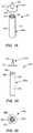
- FIG. 11is a front view of a filter for a product bag having a single looped hollow fiber membrane contained within a filter body;
- FIG. 12is a front view of a filter for a product bag having a plurality of looped hollow fiber membranes contained within a filter body;
- FIG. 13is a front view of a plurality of hollow fiber membranes secured side by side;
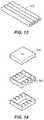
- FIG. 14is an isometric view of the securement device used for the plurality of hollow fiber membranes depicted in FIG. 13 ;
- FIG. 15is an isometric view of a fiber bundle for a product bag having a plurality of hollow fiber membranes secured in a circular holder;
- FIG. 16is an exploded perspective view of an alternative connector for use with a three-filter filter bundle
- FIG. 17is a side exploded view of the connector of FIG. 16 ;
- FIG. 18is a exploded perspective view of another alternative connector for use with a seven-filter filter bundle
- FIG. 19is a side exploded view of the connector of FIG. 18 ;
- FIG. 20is a bottom view of the connector of FIG. 19 ;
- FIG. 21is a front view of multiple product bags with sealable interconnections in a belt configuration connected to a single filter;
- FIG. 22is a front view of multiple product bags connected by sealable tubing to a single filter
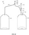
- FIG. 23is a front view of a continuous ambulatory peritoneal dialysis (CAPD) twin bag container system connected to one of the filter arrangements disclosed herein at an asymmetric Y-junction in tubing running from a solution bag of the system to a patient connector of the system; and
- CCDcontinuous ambulatory peritoneal dialysis
- FIG. 24is a front view of a continuous ambulatory peritoneal dialysis (CAPD) twin bag container system connected to one of the filter arrangements disclosed herein by direct tubing running from a solution bag of the system to the filter arrangement.
- CCDcontinuous ambulatory peritoneal dialysis
- FIGS. 1 and 2illustrate a product bag 100 that has a pre-sterilized interior and includes a bladder 102 , a stem 104 , a filter 106 disposed in-line with the stem 104 , and a sterile closure cap 108 .
- the bladder 102is a fillable pouch having a standard volume capacity with the pre-sterilized inner environment. At least partially surrounding a perimeter of the fillable pouch is a sealed border 110 having a plurality of apertures 112 configured to receive mounting hang pins during filling, administration, and/or storage.
- the bladder 102is fluidly connected to the stem 104 at an opening 114 at a first end 116 of the bladder 102 .
- Administration and medication ports 118 , 120are disposed at a second end 122 of the bladder 102 .
- the stem 104is a hollow narrow tube having an inlet 124 fluidly connected to the opening 114 of the bladder 102 .
- the stem 104includes a tapered head 126 defining the inlet 124 , a collar 128 connecting a first stem part 130 to the tapered head 126 , a second part 132 , and a duct 134 defining a stem outlet 136 .
- the sterile closure cap 108has a hemispherical shaped knob 138 attached to a neck 140 that sealably covers the inlet 124 of the stem 104 .
- the tapered head 126may be a female fitting adapted for sealingly engaging a Luer fitting of a fluid supply line during filling, for example.
- the filter 106 having a flat sheet membrane 142is disposed in-line with the stem 104 between the first and second parts 130 , 132 of the stem 104 .
- Non-limiting examples of acceptable filter membranes for the filter membrane 142are disclosed in U.S. Patent Publication No. 2012/0074064 A1 and PCT Publication No. PCT/EP2015/068004, the entire contents of which are incorporated herein by reference.
- a solutionmay enter the inlet 124 of the stem 104 and pass through the head 126 and into the first part 130 toward an inlet 144 of the filter 106 .
- the solutionthen filters through the filter membrane 142 , out a filter outlet 146 , and into the second part 132 of the stem 104 .
- the duct 134carries the filtered solution from the second part 132 to the opening 114 of the bladder 102 .
- the second part 132 of the stem 104 defined as the area of the stem between the outlet of the filter 146 and an inlet 148 of the duct 134may be identified as a “seal and cut area”.
- the phrase “seal and cut area”pertains to the manner in which the product bags are sealed and cut after being filled.
- the disclosed arrangementis designed such that after the bladder 102 is filled, a sealing mechanism can be employed to seal the stem 104 closed in the “seal and cut area,” which is below the filter membrane 142 but above the bladder 102 .
- the “seal and cut area” 132 in this versionis a portion of the stem 104 above the bladder 102 where the filter 106 does not reside. Sealing of the “seal and cut area” 132 can be achieved with a heat sealer or any other device, including for example clamping a clamp onto the “seal and cut area” 132 .
- the stem 104is cut at a location above the seal but below the filter membrane 142 . Cutting may be achieved with a knife or any other device.
- the stem 104provides an isolated fluid connection between the inlet 124 and the bladder 102 , such that once the solution is filtered through the filter membrane 142 , the filtered solution passes directly into the sterilized environment of the bladder 102 . Hence, after the bladder 102 is filled and the stem 104 is sealed and cut, the solution in the bladder 102 remains sterile until the bladder 102 is punctured or compromised. This, of course, assumes that the filter 106 was uncompromised prior to filling and performed as desired.
- a filter integrity testcan be performed on the filter 106 .
- a filter integrity testis facilitated by the arrangement of the “seal and cut area” (second part 132 ) of the stem 104 , which allows for the filter membrane 142 to be separated intact from the remainder of the now-sealed product bag 100 .
- a filter testing device(not shown) may be pre-programmed or controlled to perform a filter integrity test on the filter 106 . Examples of filter integrity tests might include a bubble test, a pressure degradation test, a water intrusion test, a water flow test, or any suitable test known in the art.
- a pressure degradation testis a method for testing the quality of a filter either before or after the filter has been used.
- the filter 106is tested after the solution passes through the filter membrane 142 and into the bladder 102 of the product bag 100 .
- a test head(not shown) engages the stem 104 and applies an air pressure of a predetermined value to the inlet 124 and filter membrane 142 .
- the pre-determined valueis the pressure where gas cannot permeate the filter membrane 142 of an acceptable filter 106 .
- a pressure sensor, or other method of measuring the integrity of the filteris located within the test head and measures the pressure decay or diffusion rate through the filter membrane 142 .
- the results from the integrity testare assessed to determine the quality of the filter 106 , and therefore the quality of the solution that previously passed through the filter 106 and into the product bag 100 . If the pressure sensor measures a decay or a unexpected rate of decay, then the filter 106 fails the test and it can be determined that the solution in the product bag is unsatisfactory. Alternatively in a bubble point test, the test head gradually increases the pressure applied to the filter 106 , and the increase in pressure is measured in parallel with the diffusion rate of the gas through the filter membrane 142 . Any disproportionate increase in diffusion rate in relation to the applied pressure may indicate a hole or other structural flaw in the filter membrane 142 , and the filter would fail the integrity test.
- the disclosed arrangement of the “seal and cut area” 132 of the product bag 100 disclosed hereinadvantageously facilitates the filter integrity test, and a determination that the solution of the filled product bag is either sterile or has the potential of being compromised may be made with a high degree of certainty.
- FIGS. 3-5An alternative product bag 150 illustrated in FIGS. 3-5 includes a similar bladder 152 and sterile closure cap 154 as that of the first product bag 100 .
- the product bag 150includes a filter 155 made from a filter membrane 170 that is disposed within (i.e., at least partially or entirely inside of) a stem 156 .
- the stem 156which may be tapered or cylindrical, does not provide a separate inlet and outlet connection ports for the filter 155 as illustrated in the product bag 100 of FIGS. 1 and 2 .
- the filter 155is a hollow fiber membrane with one sealed end 158 and one open inlet end 160 .
- a plurality of pores 162 along the surface 164 of the filter 155allow a pharmaceutical solution that entered the filter 155 at the open inlet end 160 to exit the filter 155 .
- the stem 156surrounds the filter membrane 170 in a generally concentric configuration so filtered pharmaceutical solution exiting the filter membrane 170 is contained within the stem 156 and ultimately passed into the bladder 152 .
- the product bag in FIGS. 3-55includes a “seal and cut area” 132 below the filter 155 and above a bladder 152 , wherein the “seal and cut area 132 ” facilitates separation of that portion of the stem 156 containing the filter membrane 170 .
- the filter membrane 170can be separated intact. As described above with respect to FIGS. 1 and 2 , this “seal and cut area” 132 can advantageously facilitate an integrity test procedure on the filter 155 .
- a hollow connector 166can be used to secure the stem 156 and the filter 155 together.
- the open inlet end 160 of the filter 155is sealingly connected to an open outlet end 168 of the hollow connector 166 .
- the connectionmay be achieved by gluing the open inlet end 160 of the filter 155 to the open outlet end 168 of the connector 166 with, for example, an epoxy resin, a polyurethane resin, a cyanoacrylate resin, a UV curing acrylic adhesive, or a solvent for the material of the hollow connector 166 such as cyclohexanone.
- the open outlet end 168 of the connector 166comprises a hollow cylindrical member that fits inside of and is fixed to the open inlet end 160 of the filter 155 .
- an outer diameter of the open outlet end 168 of the connector 166is substantially similar to or slightly smaller than an inner diameter of the open inlet end 160 of the filter 155 .
- the open inlet end 160 of the filter 155may be welded to the open outlet end 168 of the connector 166 by, for example, heat welding (e.g., introducing a hot conical metal tip into the open inlet end 150 of the filter 155 to partially melt it), laser welding if the hollow connector 166 is made from a material that absorbs laser radiation, mirror welding, ultrasound welding, and friction welding.
- the filter 155may be inserted into a mold, and a thermoplastic polymer may be injection-molded around it to form the hollow connector 166 .
- a thermoplastic polymermay be injection-molded around it to form the hollow connector 166 .
- Other designs and configurations for connecting the filter 155 to the connector 166are intended to be within the scope of the present disclosure.
- the hollow connector 166further includes a solution inlet 169 .
- a pharmaceutical solutioncan be fed via a connected fluid supply line, for example, into the solution inlet 169 of the hollow connector 166 .
- the solution inlet 169can include a Luer type fitting or other standard medical fitting.
- the pharmaceutical solutioncan then travel through the hollow connector 166 and exit into the filter 155 through the open outlet end 168 of the hollow connector 166 .
- the hollow connector 166also includes a sealing surface 172 to which the stem 156 is attached.
- the sealing surface 172 in this versionis cylindrical and has a diameter larger than a diameter of the open outlet end 168 , and is disposed generally concentric with the open outlet end 168 .
- the outer diameter of the sealing surface 172is generally identical to or slightly smaller than an inner diameter of the stem 156 .
- the stem 156receives the sealing surface 172 and extends therefrom to surround and protect the filter 155 without contacting the surface 164 of the filter 155 .
- the stem 156can be fixed to the sealing surface 172 with adhesive (e.g., a UV curing acrylic adhesive), epoxy, welding, bonding, etc.
- the stem 156receives the pharmaceutical solution after it passes through the pores 162 in the filter 155 . From there, the now filtered solution passes into the bladder 152 .
- FIGS. 6-10illustrate an alternative hollow connector 766 , similar to connector 166 , for securing the stem 156 and the hollow fiber filter 155 of FIGS. 3-5 together.
- the connector 766includes an open outlet end 768 carried by a stem structure that extends in a first direction from a bearing plate 777 and is adapted to be sealingly connected to the open inlet end 160 of the filter 155 .
- the connectionmay be achieved by gluing the open inlet end 160 of the filter 155 to the open outlet end 768 of the connector 766 with, for example, an epoxy resin, a polyurethane resin, a cyanoacrylate resin, a UV curing acrylic adhesive, or a solvent for the material of the hollow connector 766 such as cyclohexanone.
- the stem structure of the open outlet end 768 of the connector 766comprises a hollow cylindrical member that fits inside of and is fixed to the open inlet end 160 of the filter 155 .
- an outer diameter of the open outlet end 768 of the connector 766is substantially similar to or slightly smaller than an inner diameter of the open inlet end 160 of the filter 155 .
- the open inlet end 160 of the filter 155may be welded to the open outlet end 768 of the connector 766 by, for example, heat welding (e.g., introducing a hot conical metal tip into the open inlet end 150 of the filter 155 to partially melt it), laser welding if the hollow connector 766 is made from a material that absorbs laser radiation, mirror welding, ultrasound welding, and friction welding.
- heat weldinge.g., introducing a hot conical metal tip into the open inlet end 150 of the filter 155 to partially melt it
- laser weldingif the hollow connector 766 is made from a material that absorbs laser radiation
- mirror weldinge.g., introducing a hot conical metal tip into the open inlet end 150 of the filter 155 to partially melt it
- laser weldingif the hollow connector 766 is made from a material that absorbs laser radiation
- mirror weldinge.g., introducing a hot conical metal tip into the open inlet end 150 of the filter 155 to partially melt it
- laser weldingif the hollow
- the hollow connector 766further includes a solution inlet 769 , which is also a stem structure, extending in a second direction (opposite the first direction) from the bearing plate 777 .
- a pharmaceutical solutioncan be fed via a connected fluid supply line, for example, into the solution inlet 769 of the hollow connector 766 .
- the solution inlet 769can include a Luer type fitting or other standard medical fitting. The pharmaceutical solution can then travel through the hollow connector 766 and exit into the filter 155 through the open outlet end 768 of the hollow connector 766 .
- the hollow connector 766also includes a sealing surface 772 to which the stem 156 is attached.
- the sealing surface 772 in this versionis a cylindrical shroud extending from the bearing plate 777 in the first direction and has a diameter larger than a diameter of the open outlet end 768 .
- the sealing surface 772is disposed generally concentric with the open outlet end 768 .
- the shroud of the sealing surface 772surrounds the stem structure of the open outlet end 768 such that an annular gap 779 resides between the two.
- the outer diameter of the sealing surface 772is generally identical to or slightly smaller than an inner diameter of the stem 156 .
- the sealing surface 772 of the connector 766can be received by the stem 156 such that the stem 156 extends therefrom to surround and protect the filter 155 without contacting the surface 164 of the filter 155 .
- the stem 156can be fixed to the sealing surface 772 with adhesive (e.g., a UV curing acrylic adhesive), epoxy, welding, bonding, etc.
- adhesivee.g., a UV curing acrylic adhesive
- the stem 156receives the pharmaceutical solution after it passes through the pores 162 in the filter 155 . From there, the now filtered solution passes into the bladder 152 in the same manner described above with respect to FIGS. 3-5 .
- the filter 155may include multiple filter membranes 170 . A few non-limiting examples of multiple membrane filters will be discussed below.
- the connector 166 in FIG. 5can include a sterile closure cap 154 covering the solution inlet 168 to prevent contaminants from entering the product bag prior to being filled.
- the stem 156includes an inner diameter that is larger than an outer diameter of the filter membrane 170
- the stem 156includes a longitudinal dimension that is larger than a longitudinal dimension of the filter membrane 170 .
- the filter membrane 170resides entirely within (i.e., entirely inside of) the stem 156 and a gap exists between the inner sidewall of the stem 156 and the outer sidewall of the filter membrane 170 .
- solution passing into the filter membrane 170passes out of the plurality of pores 162 and flows without obstruction through the gap and along the inside of the stem 156 to the bladder.
- the stem 156can be a flexible tube, a rigid tube, or can include a tube with portions that are flexible and other portions that are rigid. Specifically, in some versions, a stem 156 with at least a rigid portion adjacent to the filter membrane 170 can serve to further protect the filter membrane 170 and/or prevent the filter membrane 170 from becoming pinched or kinked in a flexible tube. In other versions, such protection may not be needed or desirable.
- the stem 156has an internal diameter in the range of approximately 2.5 mm to approximately 8 mm, and a longitudinal dimension in the range of approximately 5 cm to approximately 30 cm. In one embodiment, the internal diameter of the stem 156 is about 0.2 to about 3 mm larger than the outer diameter of the filter membrane 170 .
- the filter membrane 170has an outer diameter in the range of approximately 2.3 mm to approximately 5 mm, a longitudinal dimension in the range of approximately 3 cm to approximately 20 cm, and a wall thickness in the range of approximately 150 ⁇ m to approximately 500 ⁇ m.
- each of the plurality of pores 162 in the filter membrane 170have a diameter less than or equal to approximately 0.2 microns.
- each porehas a diameter less than or equal to a value in a range of approximately 0.1 microns to approximately 0.5 microns, for instance, approximately 0.2 to approximately 0.4 microns.
- each porehas a diameter that is less than or equal to approximately 0.22 microns.
- each porehas a diameter that is less than or equal to a value in a range of approximately 0.1 microns to approximately 0.2 microns. In some versions, each pore has a diameter that is less than or equal to a value in a range of approximately 0.1 microns to approximately 0.22 microns.
- Suitable materials for the filter membrane 170can include polyolefins (e.g., PE, PP), polyvinylidene fluoride, polymethylmethacrylate, polyacrylonitrile, polysulfone, and polyethersulfone.
- the filter 155may be comprised of a blend of polysulfone or polyethersulfone and polyvinylpyrrolidone.
- the filter membrane 170can include a polymer containing cationic charges, e.g. polymers bearing functional groups like quaternary ammonium groups. A suitable example for such polymers is polyethyleneimine.
- the filter membrane 170may be manufactured by known techniques including, e.g., extrusion, phase inversion, spinning, chemical vapor deposition, 3D printing, etc.
- Suitable materials for the stem 156include PVC, polyesters like PET, poly(meth)acrylates like PMMA, polycarbonates (PC), polyolefins like PE, PP, or cycloolefin copolymers (COC), polystyrene (PS), silicone polymers, etc.
- the hollow fiber membrane 170 in FIG. 5has been described as being located within the stem 156 .
- the filter 155may include its own housing or other support structure, which is coupled to the stem 156 either in place of the connector 166 in FIG. 5 or connector 766 in FIGS. 6-10 , or at a location between two portions of the stem 156 .
- FIG. 11is a front view of a filter assembly 400 for a product bag (not pictured) having a single U-shaped hollow fiber filter membrane 402 contained within a filter body 404 .
- the filter membrane 402is secured to a filter membrane housing 406 in the U-shaped configuration with an adhesive (i.e., a UV curing acrylic adhesive), an epoxy, welding, bonding, or other means.
- the filter membrane housing 406is connected to the filter body 404 at an outlet portion 408 of the filter body 404 .
- An inlet portion 410is sealably connected to the outlet portion 408 of the filter body 404 at a joint or other seam.
- the inlet portion 410 of the filter body 404has an inlet 412 by which a pharmaceutical solution may enter the filter assembly 400 .
- the pharmaceutical solutionthen enters the filter membrane 402 through a plurality of pores 414 , travels through the filter membrane 402 , exits the filter membrane 402 at filter membrane outlets 416 , and exits the filter body 404 at filter outlet 418 .
- the filter outlet 418may then be connected to the bladder (not pictured) via the stem 256 of a product bag (not pictured).
- FIG. 11the flow of fluid through the assembly 400 has been described as moving from the inlet 412 of the inlet portion 410 to the outlet 418 of the outlet portion 408 . However, the same assembly 400 could be used in the opposite direction such that fluid enters the outlet 418 of the outlet portion 408 and exits the inlet 412 of the inlet portion 410 . In this alternative configuration, fluid would first enter the inlet 418 , pass into the filter membrane 402 at the filter membrane outlets 416 , and exit through the pores 414 and finally the inlet 412 .
- FIG. 12is an alternate embodiment of the filter assembly 400 depicted in FIG. 11 .
- the filter 420includes two U-shaped hollow fiber filter membranes 422 are secured to a filter membrane housing 424 in the U-shaped configuration with an adhesive (i.e., a UV curing acrylic adhesive), an epoxy, welding, bonding, or some other means.
- the filter membranes 422 and filter membrane housing 424are contained within a filter body 426 having an inlet portion 428 with inlet 430 sealably connected to an outlet portion 432 having filter outlet 434 .
- a filtermay include more than two U-shaped hollow fiber filter membranes arranged as depicted in FIGS. 11 and 12 .
- FIG. 12like in FIG.
- the flow of fluid through the assembly 400has been described as moving from the inlet portion 428 to the outlet portion 432 .
- the same assembly 400could be used in the opposite direction such that fluid enters the outlet portion 432 and exits the inlet portion 428 as described above relative to FIG. 11 .
- FIG. 13is a further alternative filter assembly. Specifically, in FIG. 13 , a plurality of linear membrane filters 502 are secured directly together in a parallel side-by-side configuration for what can be referred to as a fiber bundle.
- the filters 502 in FIG. 13can be secured together with adhesive (i.e., a UV curing acrylic adhesive), epoxy, welding, bonding, etc.
- adhesivei.e., a UV curing acrylic adhesive
- the plurality of filters 502can be manufactured together as one piece by way of any of the manufacturing techniques described above.
- FIG. 14provides another alternative in which a securement device 504 includes a number of blocks defining a plurality of grooves 506 identical to the number of hollow fiber membrane filters 502 .
- the blocks of the securement device 504may be sandwiched together and used to hold the plurality of hollow fiber membrane filters 502 in the side-by-side configuration.
- the securement device 504 depicted in FIG. 14allows for two sets of the hollow fiber membrane filters 502 of FIG. 13 to be stacked relative to each other.
- the fiber bundle including the membrane filters 502 and the securement device 504may be placed in a filter body, such as that discussed with respect to FIGS. 11 and 12 .
- FIG. 15is an isometric view of another version of a fiber bundle 600 for a product bag (not pictured) having a plurality of parallel hollow fiber membrane filters 502 similar to FIGS. 13 and 14 , but wherein the parallel filters 502 are arranged in a circular pattern by a circular holder 504 .
- the fiber bundle 600may be placed in a filter body, such as that discussed with respect to FIGS. 11 and 12 .
- FIGS. 16-17 and FIGS. 18-20illustrate two additional devices for coupling fiber bundles to a stem in accordance with the present disclosure.
- FIGS. 16-17discloses a connector 866 for connecting a three-fiber bundle to a stem.
- the connector 866includes a first hollow body 866 a and a second hollow body 866 b .
- the first body 866 aincludes a solution inlet 869 , which is a stem structure, extending from a bearing plate 877 .
- a pharmaceutical solutioncan be fed via a connected fluid supply line, for example, into the solution inlet 869 of the first hollow body 866 a of the connector 866 .
- the solution inlet 869can include a Luer type fitting or other standard medical fitting.
- the hollow connector 866also includes a sealing surface 872 to which the stem 156 is attached.
- the sealing surface 872 in this versionis a cylindrical shroud extending from the bearing plate 877 in a direction opposite to a direction of extension of the solution inlet 869 .
- the sealing surface 872is disposed generally concentric with the solution inlet 869 .
- the shroud of the sealing surface 872defines a cylindrical cavity (not shown in the drawings) for receiving a portion of the second hollow body 866 b of the connector 866 .
- the second hollow body 866 bincludes a support plate 880 and three open outlet ends 868 extending from the support plate 880 .
- the support plate 880includes an outer diameter that is essentially the same as or slightly smaller than an inner diameter of the cavity of the shroud of the sealing surface 872 such that when assembled, the support plate 880 is positioned into the cavity.
- the support plate 880includes a seal member 882 around its periphery to form a fluid tight seal with the inner surface of the shroud of the sealing surface 872 when inserted into the cavity. Friction, adhesive, or some other means may retain the support plate 880 in connection with the shroud of the sealing surface 872 .
- the second body 866 bincludes three open outlet ends 868 extending from the support plate 880 .
- Each open outlet end 868is adapted to be sealingly connected to an open inlet end 160 of one of three filters 155 .
- the connectionmay be achieved by gluing open inlet ends 160 of the filters 155 to the open outlet ends 868 with, for example, an epoxy resin, a polyurethane resin, a cyanoacrylate resin, a UV curing acrylic adhesive, or a solvent for the material of the hollow connector 766 such as cyclohexanone.
- the stem structure of the open outlet ends 868 of the connector 866comprises a hollow cylindrical member that fits inside of and is fixed to the open inlet ends 160 of the filters 155 .
- an outer diameter of the open outlet ends 868is substantially similar to or slightly smaller than an inner diameter of the open inlet ends 160 of the filters 155 .
- the filters 155may be welded to the open outlet ends 868 of the connector 866 by, for example, heat welding (e.g., introducing a hot conical metal tip into the open inlet ends 150 of the filters 155 to partially melt it), laser welding if the hollow connector 866 is made from a material that absorbs laser radiation, mirror welding, ultrasound welding, and friction welding.
- the filters 155may be inserted into a mold, and a thermoplastic polymer may be injection-molded around it to form the hollow connector 866 .
- Other designs and configurations for connecting the filters 155 to the open outlet ends 868are intended to be within the scope of the present disclosure.
- the sealing surface 872 of the connector 866can be received by the stem 156 such that the stem 156 extends therefrom to surround and protect the filters 155 without contacting the surfaces 164 of the filters 155 .
- the stem 156can be fixed to the sealing surface 872 with adhesive (e.g., a UV curing acrylic adhesive), epoxy, welding, bonding, etc.
- adhesivee.g., a UV curing acrylic adhesive
- the stem 156receives the pharmaceutical solution after it passes through the pores 162 in the filter 155 . From there, the now filtered solution passes into the bladder 152 in the same manner described above with respect to FIGS. 3-5 .
- FIGS. 18-20discloses a connector 966 for connecting a seven-fiber bundle to a stem.
- the connector 966includes a first hollow body 966 a and a second hollow body 966 b that can be connected to the first hollow body 966 a with an adhesive or via other means.
- the first body 966 aincludes a solution inlet 969 , which is a stem structure, extending from a bearing plate 977 .
- a pharmaceutical solutioncan be fed via a connected fluid supply line, for example, into the solution inlet 969 of the first hollow body 966 a of the connector 966 .
- the solution inlet 969can include a Luer type fitting or other standard medical fitting.
- the second hollow body 866 bincludes a hollow cylindrical support collar 980 in which seven hollow fiber membrane filters 955 can be disposed parallel to each other, as shown in FIGS. 18 and 20 .
- the support collar 980can include a support plate 982 carrying seven open outlet ends 968 extending into the collar 980 for connecting to the filters 955 in a manner similar to that described above regarding FIGS. 16-17 .
- the connectionmay be achieved by gluing the filters 955 to the open outlet ends 968 with, for example, an epoxy resin, a polyurethane resin, a cyanoacrylate resin, a UV curing acrylic adhesive, or a solvent for the material of the hollow connector 966 such as cyclohexanone.
- the stem structure of the open outlet ends 868 of the connector 866comprises a hollow cylindrical member that fits inside of and is fixed to the filters 955 .
- a diameter of the open outlet ends 968is substantially similar to or slightly smaller than an inner diameter of the filters 955 .
- the filters 955may be welded to the open outlet ends 968 of the connector 966 by, for example, heat welding (e.g., introducing a hot conical metal tip into the filters 955 to partially melt it), laser welding if the hollow connector 966 is made from a material that absorbs laser radiation, mirror welding, ultrasound welding, and friction welding.
- the filters 955may be inserted into a mold, and a thermoplastic polymer may be injection-molded around it to form the hollow connector 966 .
- Other designs and configurations for connecting the filters 955 to the open outlet ends 968are intended to be within the scope of the present disclosure.
- the collar 980 of this embodimentincludes a sealing surface 972 that can be received by the stem 156 such that the stem 156 extends therefrom.
- the stem 156can be fixed to the sealing surface 972 with adhesive (e.g., a UV curing acrylic adhesive), epoxy, welding, bonding, etc.
- adhesivee.g., a UV curing acrylic adhesive
- the stem 156receives the pharmaceutical solution after it passes through the pores 162 in the filters 955 . From there, the now filtered solution passes into the bladder 152 in the same manner described above with respect to FIGS. 3-5 .
- FIG. 21provides a multi-bag filling set containing three product bags 200 a , 200 b , and 200 c (but it could contain any number or plurality of product bags) similar to product bags 100 and 150 except that they are arranged in series and a single filter 206 is used to fill all three product bags 200 a , 200 b , and 200 c in a sequential order (i.e., in series).
- product bags 200 a , 200 b , and 200 chave administration ports 204 a , 204 b , and 204 c and could also include medication ports (not shown).
- the bladders 202 a , 202 b , and 202 care connected at edges 206 a and 206 b .
- the edges 206 a , 206 beach have an opening 208 a and 208 b , and the openings 208 a , 208 b put all three bladders 202 a , 202 b , and 202 c in fluid communication with each other.
- One of the bladders 202 ahas an inlet 210 that is connected to a stem 212 and a filter 206 .
- the stem 212 and filter 206 in FIG. 21can be arranged in any of the manners described above.
- filtered solutionpasses through the stem 212 and filter 206 , enters the inlet 210 , travels through the openings 208 a and 208 b , and ultimately fills all three bladders 202 a , 202 b , and 202 c .
- the bladders 202 a , 202 b , 202 cmay fill in series or simultaneously. For example, if the product bags 200 a , 200 b , 200 c are oriented as depicted in FIG.
- bladders 202 a , 202 b , 202 cwill tend to fill simultaneously as solution is moved through the inlet 210 . But, if the product bags 200 a , 200 b , 200 c are rotated ninety degrees counterclockwise relative to the orientation of FIG. 21 , bladder 202 a will fill first, then bladder 202 b will fill, and then finally bladder 202 c will fill last. Once the bladders 202 a , 202 b , and 202 c are full, the inlet 210 and the openings 208 a and 208 b can be sealed. Then the edges can be cut to separate the three product bags 200 a , 200 b , and 200 c.
- FIG. 22provides a multi-bag filling set having three product bags 300 a , 300 b , and 300 c connected by sealable tubing 302 to a single filter 304 , which may be one of the filters discussed above.
- a first part 306 of the sealable tubing 302is connected to the filter 304 or to a stem (not pictured) surrounding the filter 304 .
- the first part 306 of the sealable tubing 302extends to a juncture 308 where a plurality of second parts 310 of sealable tubing 302 are connected at their respective first ends 312 .
- Each second part 310is connected at a second end 314 to a respective bladder 316 of product bags 300 a , 300 b , and 300 c .
- fluidcan be introduced into the filter 304 and past to the products bags 300 a , 300 b , 300 c via the second parts 310 of sealable tubing 302 .
- fluidmay pass generally simultaneously and generally in equal portions from the filter 304 to the second parts 310 of sealable tubing 302 thereby generally simultaneously filling each of the product bags 300 a , 300 b , 300 c .
- fluidmay pass generally sequentially to the different product bags 300 a , 300 b , 300 c .
- fluidmay first pass from the filter 304 to the first product bag 300 a , valves (not shown) associated with the second and third product bags 300 b , 300 c are closed.
- a valve (not shown) with the first bag 300 acan be closed and the valve associated with the second bag 300 b can be opened to provide for filling of the second bag 300 b .
- the valve (not shown) with the second bag 300 bcan be closed and the valve associated with the third bag 300 c can be opened to provide for filling of the third bag 300 c .
- the valve (not shown) with the third bag 300 ccan be closed.
- valves associated with the bags 300 a , 300 b , 300 ccan be positioned on the second parts 310 of the sealable tubing 302 associated with each of the bags 300 a , 300 b , 300 c or on the bags 300 a , 300 b , 300 c themselves.
- the systemcould include a single three-way valve disposed at the juncture 308 for directing fluid toward and away from the various bags 300 a , 300 b , 300 c.
- FIG. 23provides a continuous ambulatory peritoneal dialysis (CAPD) twin bag container system 1002 having a solution bag 1004 and a drain bag 1006 .
- An injection site 1008is provided on the solution bag 1004 for medication additives.
- Tubing 1010runs from the solution bag 1004 to a filter Y-junction 1012 and then to a patient connector 1014 .
- a connection tube 1016i.e., stem
- connects a filter assembly 1018such as any of those described above, to the filter Y-junction 1012 and consequently to the solution bag 1004 .
- the tubing 1010may have a frangible portion 1020 near the patient connector 1014 .
- the frangible portion 120can be located closer to the Y-junction 1020 or midway between the Y-junction 1020 and the patient connector 1014 .
- Tubing 1022runs from the drain bag 1006 to the patient connector 1014 .
- the patient connector 1014is configured to interface with the transfer set of a patient's PD catheter (not pictured) at the time of use.
- the patient connector 1014has a Y-junction 1024 where tubing 1010 and tubing 1022 are connected.
- a sterility protector 1026is provided on the patient connector 1014 .
- FIG. 24provides a CAPD twin bag container system 1002 similar to that depicted in FIG. 23 except it does not have a filter Y-junction 1012 . Instead, connection tube 1016 (i.e., stem) connects directly to the solution bag 1004 . In FIG. 24 , the connection tube 1016 is connected to the solution bag 1004 at a location between the tubing 1010 and injection site 1008 , but this is merely one example, and other arrangements are possible.
- connection tube 1016i.e., stem
- the filter assembly 1018 depicted in FIGS. 23 and 24could be any of the filter assemblies discussed above.
- the filter assembly 1018could be the filter 106 having a flat sheet membrane 142 of FIGS. 1 and 2 or the filter 155 that is a hollow fiber membrane of FIGS. 3-5 secured by either connector 166 or 766 .
- the filter assembly 1018could be the filter assembly 400 having a single U-shaped hollow filter fiber membrane 402 contained within a filter body 404 of FIG. 11 or the alternate filter assembly 400 comprising two U-shaped hollow fiber filter membranes 422 of FIG. 12 .
- the filter assemblycould be the plurality of linear membrane filters 502 secured side-by-side of FIG. 13 optionally with the securement device 504 of FIG. 14 or the fiber bundle 600 of FIG. 16 optionally held together by any of a connector such as connector 866 or 966 .
Landscapes
- Health & Medical Sciences (AREA)
- Chemical Kinetics & Catalysis (AREA)
- Chemical & Material Sciences (AREA)
- Veterinary Medicine (AREA)
- Life Sciences & Earth Sciences (AREA)
- Animal Behavior & Ethology (AREA)
- General Health & Medical Sciences (AREA)
- Public Health (AREA)
- Heart & Thoracic Surgery (AREA)
- Pharmacology & Pharmacy (AREA)
- Engineering & Computer Science (AREA)
- Hematology (AREA)
- Anesthesiology (AREA)
- Biomedical Technology (AREA)
- Urology & Nephrology (AREA)
- Vascular Medicine (AREA)
- Water Supply & Treatment (AREA)
- Emergency Medicine (AREA)
- Pulmonology (AREA)
- Separation Using Semi-Permeable Membranes (AREA)
- External Artificial Organs (AREA)
- Medical Preparation Storing Or Oral Administration Devices (AREA)
- Materials For Medical Uses (AREA)
- Basic Packing Technique (AREA)
- Packages (AREA)
- Bag Frames (AREA)
- Apparatus Associated With Microorganisms And Enzymes (AREA)
Abstract
Description
Claims (31)
Priority Applications (1)
| Application Number | Priority Date | Filing Date | Title |
|---|---|---|---|
| US16/070,009US10617603B2 (en) | 2016-01-22 | 2017-01-20 | Sterile solutions product bag |
Applications Claiming Priority (3)
| Application Number | Priority Date | Filing Date | Title |
|---|---|---|---|
| US201662281799P | 2016-01-22 | 2016-01-22 | |
| US16/070,009US10617603B2 (en) | 2016-01-22 | 2017-01-20 | Sterile solutions product bag |
| PCT/US2017/014253WO2017127625A1 (en) | 2016-01-22 | 2017-01-20 | Sterile solutions product bag |
Related Parent Applications (1)
| Application Number | Title | Priority Date | Filing Date |
|---|---|---|---|
| PCT/US2017/014253A-371-Of-InternationalWO2017127625A1 (en) | 2016-01-22 | 2017-01-20 | Sterile solutions product bag |
Related Child Applications (1)
| Application Number | Title | Priority Date | Filing Date |
|---|---|---|---|
| US16/711,338ContinuationUS11564867B2 (en) | 2016-01-22 | 2019-12-11 | Sterile solutions product bag |
Publications (2)
| Publication Number | Publication Date |
|---|---|
| US20190021947A1 US20190021947A1 (en) | 2019-01-24 |
| US10617603B2true US10617603B2 (en) | 2020-04-14 |
Family
ID=57966150
Family Applications (2)
| Application Number | Title | Priority Date | Filing Date |
|---|---|---|---|
| US16/070,009ActiveUS10617603B2 (en) | 2016-01-22 | 2017-01-20 | Sterile solutions product bag |
| US16/711,338Active2038-07-06US11564867B2 (en) | 2016-01-22 | 2019-12-11 | Sterile solutions product bag |
Family Applications After (1)
| Application Number | Title | Priority Date | Filing Date |
|---|---|---|---|
| US16/711,338Active2038-07-06US11564867B2 (en) | 2016-01-22 | 2019-12-11 | Sterile solutions product bag |
Country Status (26)
| Country | Link |
|---|---|
| US (2) | US10617603B2 (en) |
| EP (2) | EP3616676B1 (en) |
| JP (2) | JP6637606B2 (en) |
| KR (1) | KR101964576B1 (en) |
| CN (1) | CN108495610B (en) |
| AU (2) | AU2017210313B2 (en) |
| BR (1) | BR112018013901B1 (en) |
| CA (1) | CA3011511C (en) |
| CO (1) | CO2018006818A2 (en) |
| DE (1) | DE112017000470T5 (en) |
| DK (1) | DK3405161T3 (en) |
| ES (1) | ES2767743T3 (en) |
| GB (1) | GB2562959A (en) |
| HR (1) | HRP20200073T1 (en) |
| HU (1) | HUE047651T2 (en) |
| IL (1) | IL260097B (en) |
| MX (1) | MX2018008877A (en) |
| MY (1) | MY191758A (en) |
| NZ (1) | NZ743293A (en) |
| PH (2) | PH12018501561B1 (en) |
| PL (1) | PL3405161T3 (en) |
| PT (1) | PT3405161T (en) |
| RU (1) | RU2732111C2 (en) |
| SI (1) | SI3405161T1 (en) |
| TR (1) | TR201809267T2 (en) |
| WO (1) | WO2017127625A1 (en) |
Cited By (3)
| Publication number | Priority date | Publication date | Assignee | Title |
|---|---|---|---|---|
| US20200146932A1 (en)* | 2017-07-17 | 2020-05-14 | Baxter International Inc. | Medical Product Including Pre-Filled Product Bag |
| WO2022146758A2 (en) | 2020-12-28 | 2022-07-07 | Baxter International Inc. | Method and system for producing sterile solution filled containers |
| US11857497B2 (en) | 2022-03-08 | 2024-01-02 | Equashield Medical Ltd | Fluid transfer station in a robotic pharmaceutical preparation system |
Families Citing this family (15)
| Publication number | Priority date | Publication date | Assignee | Title |
|---|---|---|---|---|
| ES3004613T3 (en) | 2009-07-29 | 2025-03-12 | Icu Medical Inc | Fluid transfer devices |
| KR102145639B1 (en) | 2011-12-22 | 2020-08-19 | 아이씨유 메디칼 인코퍼레이티드 | Fluid transfer devices and methods of use |
| ES2805051T3 (en) | 2013-11-25 | 2021-02-10 | Icu Medical Inc | Procedures and system for filling I.V. bags with therapeutic liquid |
| EP4534065A3 (en) | 2015-12-04 | 2025-06-04 | ICU Medical, Inc. | Systems methods and components for transferring medical fluids |
| USD851745S1 (en) | 2016-07-19 | 2019-06-18 | Icu Medical, Inc. | Medical fluid transfer system |
| EP3487468B1 (en) | 2016-07-25 | 2025-10-01 | ICU Medical, Inc. | Systems and components for trapping air bubbles in medical fluid transfer modules and systems |
| EP3388141A1 (en)* | 2017-04-12 | 2018-10-17 | Gambro Lundia AB | Filtration device |
| EP3431171A1 (en)* | 2017-07-19 | 2019-01-23 | Gambro Lundia AB | Filter membrane and device |
| US11382543B2 (en)* | 2018-06-11 | 2022-07-12 | Edwards Lifesciences Corporation | Tubing system for use in a blood sampling-blood pressure monitoring system |
| CN113825532A (en)* | 2019-04-08 | 2021-12-21 | 香港商路申西亚公司 | Peritoneal dialysis apparatus |
| EP3845299B1 (en)* | 2019-12-31 | 2022-06-22 | Gambro Lundia AB | Hollow fiber membrane transport cartridge |
| EP3845301A1 (en)* | 2019-12-31 | 2021-07-07 | Gambro Lundia AB | Process for manufacturing a sterilizing filter |
| US11590057B2 (en) | 2020-04-03 | 2023-02-28 | Icu Medical, Inc. | Systems, methods, and components for transferring medical fluids |
| IT202000025105A1 (en)* | 2020-10-22 | 2022-04-22 | Baxter Int | MEDICAL FLUID GENERATION SYSTEM |
| IT202000025108A1 (en) | 2020-10-22 | 2022-04-22 | Baxter Int | MEDICAL FLUID GENERATION SYSTEM |
Citations (229)
| Publication number | Priority date | Publication date | Assignee | Title |
|---|---|---|---|---|
| SU247843A1 (en) | В. П. Бобраков, М. А. Сирота, Г. Г. Лукь ненко, Е. И. Скуратов, Ф. Лерман , Д. В. Чумак | DEVICE FOR FILLING A TARE WITH A LIQUID OR PURELENT-SHAPED PRODUCT UNDER ASEPTIC CONDITIONS | ||
| US3233384A (en) | 1960-10-14 | 1966-02-08 | Baxter Don Inc | Method of packaging a parenteral fluid |
| US3902068A (en) | 1974-04-10 | 1975-08-26 | Modern Controls Inc | Method and apparatus for measuring the gas transmission through packaging materials |
| US3938519A (en) | 1974-02-26 | 1976-02-17 | American Hospital Supply Corporation | Medical liquid container with a toggle film leak tester and method of leak testing with same |
| US4036698A (en) | 1974-11-06 | 1977-07-19 | Millipore Corporation | Method and apparatus for membrane filter sterility testing |
| US4116646A (en) | 1977-05-20 | 1978-09-26 | Millipore Corporation | Filter unit |
| US4265760A (en) | 1979-02-26 | 1981-05-05 | Becton Dickinson & Company | Device for dilution and delivery of in vivo chemicals |
| US4353398A (en) | 1981-01-05 | 1982-10-12 | Automatic Liquid Packaging, Inc. | Sterilizing apparatus for an encapsulating machine |
| US4360435A (en) | 1979-11-01 | 1982-11-23 | Baxter Travenol Laboratories, Inc. | Process for sterilizing and transferring a solution |
| US4369898A (en) | 1977-03-09 | 1983-01-25 | Ake Andersson | Filling machine |
| JPS5840202U (en) | 1981-09-07 | 1983-03-16 | 三菱レイヨン株式会社 | Precision “ro” |
| DE3238649A1 (en) | 1982-10-19 | 1984-04-19 | Hagen Dr. 8520 Erlangen Theuer | Multicompartment bag for mixed infusion solutions |
| EP0116362A2 (en) | 1983-02-11 | 1984-08-22 | Millipore Corporation | Sterile package for therapeutic composition |
| US4502614A (en) | 1981-01-05 | 1985-03-05 | Automatic Liquid Packaging, Inc. | Sterilizing apparatus for an encapsulating machine |
| US4507114A (en) | 1983-10-21 | 1985-03-26 | Baxter Travenol Laboratories, Inc. | Multiple chamber container having leak detection compartment |
| JPS6058530A (en) | 1983-09-09 | 1985-04-04 | Fujisawa Pharmaceut Co Ltd | Method and apparatus for testing membrane filter |
| DE3333283A1 (en) | 1983-09-15 | 1985-04-18 | Gerhard 3429 Krebeck Lorenz | Treatment system for infusion solutions |
| US4515007A (en) | 1983-01-04 | 1985-05-07 | The United States Of America As Represented By The United States Department Of Energy | Method of and apparatus for testing the integrity of filters |
| US4521366A (en) | 1982-06-24 | 1985-06-04 | Baxter Travenol Laboratories, Inc. | Method for closing and sealing plastic tubing using a hot die and a rotating cold die |
| JPS6091203U (en) | 1983-11-28 | 1985-06-22 | 旭化成株式会社 | Syringe type mini separator |
| GB2153247A (en) | 1984-01-31 | 1985-08-21 | Baxter Travenol Lab | Filter |
| JPS60197287A (en) | 1984-03-19 | 1985-10-05 | Fujisawa Pharmaceut Co Ltd | Aseptic filter apparatus of liquid |
| US4547289A (en) | 1983-02-28 | 1985-10-15 | Yoshihiro Okano | Filtration apparatus using hollow fiber membrane |
| US4610790A (en) | 1984-02-10 | 1986-09-09 | Sterimatics Company Limited Partnership | Process and system for producing sterile water and sterile aqueous solutions |
| US4623516A (en) | 1981-01-05 | 1986-11-18 | Automatic Liquid Packaging, Inc. | Sterilizing method for an encapsulating machine |
| JPS621410A (en) | 1985-06-26 | 1987-01-07 | Kitazawa Valve:Kk | Precision filter device |
| US4636313A (en) | 1984-02-03 | 1987-01-13 | Vaillancourt Vincent L | Flexible filter disposed within flexible conductor |
| US4636307A (en) | 1983-09-16 | 1987-01-13 | Mitsubishi Rayon Co., Ltd. | Hollow-fiber filtering module and water purification device utilizing it |
| US4668401A (en) | 1985-06-19 | 1987-05-26 | Mitsubishi Rayon Co., Ltd. | Hollow-fiber filter module and filtration method using the same |
| US4671762A (en) | 1982-04-01 | 1987-06-09 | Automatic Liquid Packaging, Inc. | Apparatus for filling a molded container with liquid contents |
| US4695382A (en) | 1985-11-18 | 1987-09-22 | Microgon, Inc. | Combined fluid filter and delivery tubing |
| US4712590A (en) | 1986-05-30 | 1987-12-15 | Baxter Travenol Laboratories, Inc. | Electrical connection means for multiple bulk compounding systems |
| US4730435A (en) | 1986-04-07 | 1988-03-15 | Aqua-Chem, Inc. | Sterile docking system for filling IV bags |
| US4738782A (en) | 1984-04-28 | 1988-04-19 | Kanegafuchi Kagaku Kogyo Kabushiki Kaisha | Method and apparatus for aseptic filtration |
| WO1988003829A1 (en) | 1986-11-24 | 1988-06-02 | Alfa-Laval Food Engineering Ab | Arrangement in membrane filter |
| US4779448A (en) | 1986-01-28 | 1988-10-25 | Donaldson Company, Inc. | Photoelectric bubble detector apparatus and method |
| US4807676A (en) | 1985-02-26 | 1989-02-28 | Baxter International Inc. | Fluid transfer workstation |
| US4820297A (en) | 1986-12-12 | 1989-04-11 | Baxter International Inc. | Fluid delivery system with integrally formed sample cell |
| EP0314822A1 (en) | 1987-11-02 | 1989-05-10 | Pall Corporation | Apparatus and process for fluid flow control |
| JPH01139108A (en) | 1987-11-25 | 1989-05-31 | Fuji Photo Film Co Ltd | Filtration system |
| US4842028A (en) | 1987-05-13 | 1989-06-27 | Baxter International Inc. | Fluid transfer apparatus |
| US4872974A (en) | 1983-09-09 | 1989-10-10 | Fujisawa Pharmaceutical Co., Ltd. | Apparatus for testing membrane filters, and for sterilizing liquids with use of membrane filter |
| US4881176A (en) | 1988-01-22 | 1989-11-14 | Anthony Kononov | Filter analyzing system |
| US4915847A (en) | 1987-08-04 | 1990-04-10 | Baxter International Inc. | Cryoglobulin separation |
| US4937194A (en) | 1986-05-12 | 1990-06-26 | Baxter International Inc. | Method for metering nutrient media to cell culture containers |
| US4943287A (en) | 1989-07-17 | 1990-07-24 | Miles Inc. | Red blood cell storage system |
| JPH02290228A (en) | 1988-12-22 | 1990-11-30 | Asahi Chem Ind Co Ltd | Regenerated cellulose hollow fiber membrane microfiltration module |
| JPH038420A (en) | 1989-06-05 | 1991-01-16 | Fuji Photo Film Co Ltd | Method for testing perfectness |
| JPH03110445A (en) | 1989-09-25 | 1991-05-10 | Fuji Photo Film Co Ltd | Completeness testing method |
| EP0476194A1 (en) | 1989-01-24 | 1992-03-25 | James A. Benn | Bag filling method and bag set for preparing pharmaceutical sterile solutions |
| USRE33924E (en) | 1986-07-16 | 1992-05-12 | Autologous Blood Corp. | Apparatus and method for storing and processing blood |
| JPH04142445A (en) | 1990-10-02 | 1992-05-15 | Fuji Photo Film Co Ltd | Completeness testing method |
| JPH04348252A (en) | 1991-01-16 | 1992-12-03 | House Food Ind Co Ltd | Method and device for inspecting integrity of membrane filter |
| US5180504A (en) | 1991-05-22 | 1993-01-19 | Baxter International Inc. | Systems and methods for removing undesired matter from blood cells |
| JPH0523551A (en) | 1991-07-18 | 1993-02-02 | Fuji Photo Film Co Ltd | Perfection testing apparatus |
| US5209044A (en) | 1991-07-11 | 1993-05-11 | Innovative Automation Inc. | Automatic tube filling device and process |
| US5221474A (en) | 1990-12-28 | 1993-06-22 | Terumo Kabushiki Kaisha | Transfusion filtering device |
| US5249409A (en) | 1992-06-02 | 1993-10-05 | Mhb Industries Corp. | Method and apparatus for manufacture of wicketed bags with an encapsulated article and the bags formed thereby |
| US5275724A (en) | 1991-12-10 | 1994-01-04 | Millipore Corporation | Connector apparatus and system |
| JPH0634636A (en) | 1992-07-17 | 1994-02-10 | Tosoh Corp | Steroid hormone assay |
| EP0582822A1 (en) | 1992-06-30 | 1994-02-16 | Millipore Corporation | Integrity test for membranes |
| JPH0643089A (en) | 1992-05-01 | 1994-02-18 | Nippon Memutetsuku Kk | Apparatus for testing completeness of membrane filter |
| US5310094A (en) | 1991-11-15 | 1994-05-10 | Jsp Partners, L.P. | Preservative free sterile fluid dispensing system |
| US5353630A (en) | 1992-05-01 | 1994-10-11 | Memtec Japan Limited | Apparatus for testing membrane filter integrity |
| US5368586A (en) | 1991-06-21 | 1994-11-29 | Npbi Nederlands Produktielaboratorium Voor Bloedtransfusieapparatuur En Infusievloeistoffen B.V. | Closure for a drug-vial |
| DE4339589C1 (en) | 1993-11-20 | 1994-12-08 | Sartorius Gmbh | Method and device for testing filter elements using a water intrusion test |
| US5417101A (en) | 1991-06-10 | 1995-05-23 | Pall Corporation | Method and apparatus for testing the integrity of filter elements |
| EP0667954A1 (en) | 1992-11-06 | 1995-08-23 | Pall Corporation | System and method for testing the integrity of porous elements |
| US5476592A (en) | 1993-04-27 | 1995-12-19 | Hospal Industrie | Method and device for injection of a sterile and antipyrogenic fluid |
| US5480554A (en) | 1992-05-13 | 1996-01-02 | Pall Corporation | Integrity-testable wet-dry-reversible ultrafiltration membranes and method for testing same |
| US5488811A (en) | 1995-02-21 | 1996-02-06 | Abbott Laboratories | On-line air filter integrity testing apparatus |
| US5490848A (en) | 1991-01-29 | 1996-02-13 | The United States Of America As Represented By The Administrator Of The National Aeronautics And Space Administration | System for creating on site, remote from a sterile environment, parenteral solutions |
| US5493845A (en) | 1993-04-01 | 1996-02-27 | Abbott Laboratories | Method for forming, filling and sealing a sterile flexible container |
| US5507959A (en) | 1994-11-04 | 1996-04-16 | Advanced Micro Devices, Inc. | Apparatus for wetting, flushing and performing integrity checks on encapsulated PTFE filters |
| WO1996014913A1 (en) | 1994-11-14 | 1996-05-23 | W.L. Gore & Associates, Inc. | Hydrophilized filter cartridge and process for making same |
| US5538638A (en) | 1994-06-27 | 1996-07-23 | Hedman; Hilary R. | Method of testing IV admixtures for contaminants |
| US5563334A (en) | 1994-04-15 | 1996-10-08 | Sartorius Ag | Filter integrity testing in clean rooms and the like |
| DE29618092U1 (en) | 1996-10-18 | 1996-12-12 | Sartorius AG, 37075 Göttingen | Integrity testable filter cassette made of hydrophilic, porous polymer membranes with improved filtration security and filtration performance |
| US5584997A (en) | 1993-09-02 | 1996-12-17 | Tsuchiya Mfg. Co., Ltd. | Separation module and bundle unit of hollow thread-type porous membrane elements and methods of producing same |
| US5594161A (en) | 1992-03-24 | 1997-01-14 | Pall Corporation | Method and apparatus for rapidly testing the integrity of filter elements |
| US5616828A (en) | 1993-08-30 | 1997-04-01 | Pfizer Inc. | Apparatus and method for testing hydrophobic filters |
| EP0624359B1 (en) | 1993-03-16 | 1997-05-14 | Victor Grifols Lucas | Apparatus for the sterile filling of sterile bags for perfusion liquids and for checking this filling |
| EP0790051A2 (en) | 1996-02-14 | 1997-08-20 | B. Braun Melsungen Ag | Flexible plastic container |
| US5674404A (en) | 1995-02-13 | 1997-10-07 | Aksys, Ltd. | Filter integrity test method for dialysis machines |
| EP0545000B1 (en) | 1991-12-05 | 1997-10-29 | Victor Grifols Lucas | An improved vessel for perfusion liquids |
| EP0820343A1 (en) | 1996-01-16 | 1998-01-28 | Corning Costar Corporation | Filter cartridges having track etched membranes and methods of making same |
| US5733619A (en) | 1992-01-30 | 1998-03-31 | Baxter International Inc. | Multilayer coextruded material for medical grade products and products made therefrom |
| US5788862A (en) | 1992-05-13 | 1998-08-04 | Pall Corporation | Filtration medium |
| JPH10225628A (en) | 1997-02-14 | 1998-08-25 | Nippon Millipore Kk | Cross filtration device |
| US5808181A (en) | 1995-09-16 | 1998-09-15 | Fresenius Ag | Method for testing a filter in a dialysis system |
| US5881535A (en) | 1996-04-09 | 1999-03-16 | Baxter International, Inc. | Apparatus and method for filling and sealing intravenous solution bags |
| US5911886A (en) | 1994-03-31 | 1999-06-15 | Inoteb | Device for filtration of cryoprecipitate and its application |
| US6059968A (en) | 1998-01-20 | 2000-05-09 | Baxter International Inc. | Systems for processing and storing placenta/umbilical cord blood |
| US6228271B1 (en) | 1996-05-28 | 2001-05-08 | Omnium De Traitement Et De Valorisation (Otv) | Method and installation for in situ testing of membrane integrity |
| US6245228B1 (en) | 2000-02-28 | 2001-06-12 | Maher I. Kelada | Emergency water treatment device |
| US6324898B1 (en) | 1999-12-21 | 2001-12-04 | Zenon Environmental Inc. | Method and apparatus for testing the integrity of filtering membranes |
| GB2362841A (en) | 2000-06-03 | 2001-12-05 | Secr Defence | Method and apparatus for testing filters |
| GB2365511A (en) | 1997-07-16 | 2002-02-20 | Pall Corp | A valve with pin and slot mechanism |
| US6358420B2 (en) | 1998-06-01 | 2002-03-19 | Baxter International Inc. | Blood collection method employing an air venting blood sample tube |
| CN2498602Y (en) | 2001-09-07 | 2002-07-03 | 国家海洋局杭州水处理技术研究开发中心 | Instrument for testing perfection of membrane filtering core |
| US20020117232A1 (en) | 2001-02-28 | 2002-08-29 | Gisper-Sauch Enric Martinell | Apparatus for filling containers for pharmaceutical uses and the like |
| US6451201B1 (en) | 2001-04-25 | 2002-09-17 | Zenon Environmental Inc. | Distributed on-line integrity testing for immersed membranes |
| DE20212749U1 (en) | 2002-08-20 | 2002-10-10 | Wang, Chih-Hung, Taipeh/T'ai-pei | Filling system for filling infusion bags |
| US20020162778A1 (en) | 2001-02-16 | 2002-11-07 | Peabody Alan M. | Automated peritoneal dialysis system and process with in-line sterilization of dialysate |
| US6495039B1 (en) | 1998-04-22 | 2002-12-17 | Whatman Hemasure, Inc. | System for in-line filtering biological liquid |
| US6504606B2 (en) | 2000-10-02 | 2003-01-07 | Scan Technology Co., Ltd. | Integrated soft bag inspection system |
| DE10151270A1 (en) | 2001-10-17 | 2003-05-08 | Sartorius Gmbh | System for monitoring integrity of filter element used in sterile filtration processes comprises filter element with integrated storage element, filtering device into which filter element is inserted, and control unit |
| US20030174306A1 (en) | 2002-03-13 | 2003-09-18 | Grant Donald C. | Dilution apparatus and method of diluting a liquid sample |
| US6660171B2 (en) | 2000-03-27 | 2003-12-09 | Peter Zuk, Jr. | High capacity gravity feed filter for filtering blood and blood products |
| US20030230521A1 (en) | 2002-06-14 | 2003-12-18 | Schick Karl G. | Single-use manifold for automated, aseptic transfer of solutions in bioprocessing applications |
| US6666970B1 (en) | 1999-06-08 | 2003-12-23 | Sartorius Ag | Process and apparatus for testing filtration unit integrity |
| US20030234211A1 (en) | 2002-06-18 | 2003-12-25 | Sartorius Ag | Method for conducting an integrity test of filter elements |
| US20040007540A1 (en) | 2002-07-10 | 2004-01-15 | Thierry Verpoort | Selective deleukocytation unit for a platelet product |
| WO2004009201A2 (en) | 2002-07-24 | 2004-01-29 | Cuno, Inc. | Polymeric surface treatment of filter media |
| US20040022696A1 (en) | 2000-05-12 | 2004-02-05 | Cti, Inc. | Method for multi-batch production of FDG |
| US20040031744A1 (en) | 1998-12-09 | 2004-02-19 | Jms Co., Ltd. | Infusion filter |
| US20040147865A1 (en) | 1994-10-13 | 2004-07-29 | Cianci James P. | System and method for processing blood |
| WO2004096319A1 (en) | 2003-04-30 | 2004-11-11 | Crb Nederland B.V. | Method and apparatus for fractionating blood |
| US20040226898A1 (en) | 2003-05-14 | 2004-11-18 | Steris Inc. | Filter cleaning and decontaminating system |
| US20040237654A1 (en) | 2001-08-06 | 2004-12-02 | Vincent Savall | Method and device for controlling the integrity of membrane filtration units |
| US6904370B1 (en) | 2003-12-30 | 2005-06-07 | Compliance Software Solutions Corp. | System, method, and computer-readable medium for collection of environmental data and generation of user report for compliance with FDA requirements |
| WO2005077499A1 (en) | 2004-02-18 | 2005-08-25 | U.S. Filter Wastewater Group, Inc. | Continuous pressure decay test |
| US20050209547A1 (en) | 2002-06-06 | 2005-09-22 | Burbank Jeffrey H | Last-chance quality check and/or air/pathogen filter for infusion systems |
| EP1579838A1 (en) | 2002-12-12 | 2005-09-28 | Asahi Kasei Kabushiki Kaisha | Virus-removing bag and virus-removing method using the same |
| US20050279419A1 (en) | 2004-06-21 | 2005-12-22 | Dennis Tribble | Automated use of a vision system to unroll a label to capture and process drug identifying indicia present on the label |
| US6983504B2 (en) | 2001-04-02 | 2006-01-10 | Sartorius Ag | Method for carrying out an integrity test for filter elements |
| US20060048486A1 (en) | 2002-06-07 | 2006-03-09 | Laing Robert J | Flexible pouch filling and heat sealing line for flexible pouches and containers for supporting and moving the flexible pouches |
| US7048775B2 (en) | 2001-10-17 | 2006-05-23 | Sartorius Ag | Device and method for monitoring the integrity of filtering installations |
| US20060124515A1 (en) | 2002-02-11 | 2006-06-15 | The Board Of Trustees Of The University Of Illinois | Methods and systems for membrane testing |
| US7166217B2 (en) | 2002-04-16 | 2007-01-23 | Gambro Inc | Methods and apparatuses for blood component separation |
| US20070079649A1 (en) | 2005-10-11 | 2007-04-12 | Millipore Corporation | Integrity testable multilayered filter device |
| EP1775002A1 (en) | 2005-10-11 | 2007-04-18 | Millipore Corporation | Integrity testable multilayered filtration device and method of manufacturing such device |
| US20070119121A1 (en) | 2005-11-28 | 2007-05-31 | Pdc Facilities, Inc. | Filling machine |
| US20070175816A1 (en) | 2002-02-13 | 2007-08-02 | Thierry Verpoort | Filtering Unit Having A Calendered Layer For Removing Leukocytes |
| US7281409B2 (en) | 2001-10-17 | 2007-10-16 | Sartorius Biotech Gmbh | Device, method and computer program product for carrying out integrity tests on filter elements |
| US20070251299A1 (en) | 2006-04-27 | 2007-11-01 | Michael Brussermann | System and method for in-process integrity test of a filter |
| EP1882486A1 (en) | 2006-07-28 | 2008-01-30 | Grifols, S.A. | Device for handling perfusion liquids with membrane filter and anti-tamper means |
| US20080051937A1 (en) | 2006-08-23 | 2008-02-28 | Forhealth Technologies, Inc. | Automated drug delivery bag filling system |
| WO2008039278A1 (en) | 2006-06-30 | 2008-04-03 | Pure Tech Water Systems, Llc | Water filtration system |
| US7354758B2 (en) | 2003-09-03 | 2008-04-08 | Sartorius Stedim Biotech Gmbh | Device and method for sterility testing |
| US20080087613A1 (en) | 2005-06-22 | 2008-04-17 | Gambro Bct, Inc. | Apparatus and Method for Separating Discrete Volumes of A Composite Liquid |
| US20080105618A1 (en) | 2006-10-27 | 2008-05-08 | Mesosystems Technology, Inc. | Method and apparatus for the removal of harmful contaminants from portable drinking water devices |
| FR2909904A1 (en) | 2006-12-19 | 2008-06-20 | Degremont Sa | Hollow fiber type filtration membrane`s e.g. ultra filtration membrane, integrity control method for water filtration assembly, involves placing sensor in water, where sensor detects gas passage in water compartment during integrity defect |
| EP1935470A1 (en) | 2006-04-12 | 2008-06-25 | Millipore Corporation | Filter with memory, communication and concentration sensor |
| US7444795B2 (en) | 2005-10-25 | 2008-11-04 | Toyo Jidoki Co., Ltd. | Gas seal-in method for a bag with a gas filling compartment and packaging method for a bag with a gas filling compartment |
| EP2012906A2 (en) | 2006-04-07 | 2009-01-14 | NxStage Medical, Inc. | Filtration system for preparation of fluids for medical applications. |
| WO2009006850A1 (en) | 2007-07-11 | 2009-01-15 | Guangzhen Meng | Hollow fiber membrane or capillary membrane filter and water filtration method using such a filter |
| EP2059443A2 (en) | 2006-08-30 | 2009-05-20 | Tema Sinergie S.r.l. | Automatic machine for fractionating a radioactive liquid |
| US7544300B2 (en) | 2003-01-07 | 2009-06-09 | Nxstage Medical, Inc. | Batch filtration system for preparation of sterile fluid for renal replacement therapy |
| US20090173685A1 (en) | 2006-06-16 | 2009-07-09 | Terumo Kabushiki Kaisha | Blood treatment filter and blood treatment circuit |
| US7592178B2 (en) | 2005-02-23 | 2009-09-22 | Hunter Menufacturing Co. | Filter integrity tester |
| US7594425B2 (en) | 2005-10-11 | 2009-09-29 | Millipore Corporation | Methods and systems for integrity testing of porous materials |
| US20090299651A1 (en) | 2008-05-29 | 2009-12-03 | Hach Company | Filtration testing system |
| US20100004602A1 (en) | 2008-07-01 | 2010-01-07 | Carmel Pharma Ab | Piercing Member Protection Device |
| US20100004619A1 (en) | 2008-07-03 | 2010-01-07 | Baxter International Inc. | Port assembly for use with needleless connector |
| US20100004588A1 (en) | 2008-07-01 | 2010-01-07 | Baxter International Inc. | Nanoclay sorbents for dialysis |
| RU2389513C2 (en) | 2004-08-10 | 2010-05-20 | Нипро Корпорейшн | Blood purification apparatus such as highly porous hollow-fibre membranes and method for manufacturing thereof |
| US7727219B2 (en) | 2001-10-22 | 2010-06-01 | Vita 34 Ag | Sterile system and methods for collecting, transporting, storing and cyropreserving body fluids |
| WO2010065810A2 (en) | 2008-12-04 | 2010-06-10 | Siemens Medical Solutions Usa, Inc. | Apparatus and method for automated quality control |
| CN201643862U (en) | 2010-04-20 | 2010-11-24 | 新乡平原航空技术工程有限公司 | Detection device for testing integrity of filter element structure |
| EP2260918A2 (en) | 2006-04-12 | 2010-12-15 | Millipore Corporation | Filter with memory, communication and pressure sensor |
| CN201732014U (en) | 2010-08-20 | 2011-02-02 | 伊马莱富(北京)制药系统有限公司 | Online integrity test system of sterile filter |
| US20110049026A1 (en) | 2009-08-26 | 2011-03-03 | Kolon Industries, Inc. | Hollow fiber membrane module for water purifier |
| US20110067485A1 (en) | 2009-09-24 | 2011-03-24 | Grant Donald C | Integrity Test Method for Porous Filters |
| US20110094619A1 (en) | 2008-02-07 | 2011-04-28 | Colin Steel | System for dispensing a fluid in non-controlled environments |
| US20110094310A1 (en) | 2006-04-12 | 2011-04-28 | Millipore Corporation | Filter with memory, communication and pressure sensor |
| DE202010017082U1 (en) | 2010-12-08 | 2011-05-12 | ITM Isotopen Technologien München AG | Apparatus for labeling molecules with radionuclides and using same to produce a radiopharmaceutical compound |
| EP2331078A1 (en) | 2008-08-27 | 2011-06-15 | Schering Corporation | Lyophilized formulatons of engineered anti-il-23p19 antibodies |
| CN102109364A (en) | 2010-12-01 | 2011-06-29 | 上海共和真空技术有限公司 | Filter integrity detecting system for freeze dryer and detecting method thereof |
| US7972515B1 (en) | 2008-10-10 | 2011-07-05 | The United States Of America As Represented By The Secretary Of The Navy | In situ membrane integrity test |
| US8003768B1 (en) | 2006-07-05 | 2011-08-23 | Decon Labs, Inc. | System for providing 20% ethanol solutions that meet bioburden and endotoxin requirements |
| WO2011154072A1 (en) | 2010-06-10 | 2011-12-15 | Sartorius Stedim Biotech Gmbh | Assembling method, operating method, augmented reality system and computer program product |
| CN102313691A (en) | 2010-07-08 | 2012-01-11 | 广州珠江啤酒股份有限公司 | Tester and test method for reverse bubble point of single filter core |
| US20120024156A1 (en) | 2009-10-12 | 2012-02-02 | New Health Sciences, Inc. | Blood storage bag system and depletion devices with oxygen and carbon dioxide depletion capabilities |
| US20120080375A1 (en) | 2010-09-30 | 2012-04-05 | Krones Ag | Method and device for manufacturing filtered liquids |
| CN102435224A (en) | 2011-11-08 | 2012-05-02 | 上海东富龙科技股份有限公司 | Online integrity testing method for filter |
| CN102430340A (en) | 2011-11-15 | 2012-05-02 | 天津瑞普高科生物药业有限公司 | A method for detecting the integrity of ultrafiltration membrane capsules |
| US8225824B2 (en) | 2007-11-16 | 2012-07-24 | Intelligent Hospital Systems, Ltd. | Method and apparatus for automated fluid transfer operations |
| WO2012103124A2 (en) | 2011-01-24 | 2012-08-02 | Emd Millipore Corporation | Accelerated mixed gas integrity testing of porous materials |
| US20120222774A1 (en) | 2010-12-29 | 2012-09-06 | Cardinal Health 414, Llc | Closed vial fill system for aseptic dispensing |
| US8271139B2 (en) | 2003-10-17 | 2012-09-18 | Asahi Kasei Bioprocess, Inc. | Multi-stage accurate blending system and method |
| US8272251B2 (en) | 2004-08-31 | 2012-09-25 | Dow Global Technologies Llc | Method for testing separation modules |
| EP2502610A1 (en) | 2011-03-23 | 2012-09-26 | Health Robotics S.r.l. | Machine for the preparation of pharmaceutical products |
| US20120282143A1 (en) | 2011-05-02 | 2012-11-08 | Express Scripts, Inc. | Methods and systems for pharmaceutical compounding |
| US20120297862A1 (en) | 2011-03-31 | 2012-11-29 | Krones Ag | Method of checking a membrane filtration module of a filtration plant |
| WO2013009765A2 (en) | 2011-07-11 | 2013-01-17 | Hyclone Laboratories, Inc. | Fluid manifold systems |
| DE10165044B4 (en) | 2001-10-17 | 2013-01-24 | Sartorius Stedim Biotech Gmbh | Filter pneumatic test assembly has control unit linked by radio transponder to communications device near the filter element under test |
| US8361320B2 (en) | 2003-09-05 | 2013-01-29 | Hemerus Medical, Llc | Biological fluid filtration apparatus |
| US8366855B2 (en) | 2006-09-12 | 2013-02-05 | Ppi Technologies Global, Llc | Automated machine and method for mounting a fitment to a flexible pouch |
| DE102011111050A1 (en) | 2011-08-24 | 2013-02-28 | Sartorius Stedim Biotech Gmbh | Method for testing the integrity of a hydrophobic, porous membrane filter |
| US20130130973A1 (en) | 2011-11-17 | 2013-05-23 | Cebix Ab | Pegylated c-peptide |
| US8499919B2 (en) | 2010-08-30 | 2013-08-06 | Health Robotics, S.r.l. | Machine for the production of pharmaceutical products |
| US20130233810A1 (en) | 2005-02-24 | 2013-09-12 | Hemerus Medical, Llc | High Capacity BIological Fluid Filtration Apparatus |
| US20130240436A1 (en) | 2012-03-15 | 2013-09-19 | Taylour Johnson | Method for Sealing Hollow Fiber Membranes |
| EP2658502A2 (en) | 2010-12-30 | 2013-11-06 | GE Healthcare UK Limited | Multi-vial dispensing |
| CN203337507U (en) | 2013-06-08 | 2013-12-11 | 南京拓鉒医药科技有限公司 | Detection device for integrity of filter membrane |
| WO2013186631A2 (en) | 2012-06-11 | 2013-12-19 | Butters Brain E | Apparatus, systems. and methods for fluid filtration |
| WO2014008400A2 (en) | 2012-07-06 | 2014-01-09 | 3-D Matrix, Inc. | Fill-finish process for peptide solutions |
| US20140012185A1 (en)* | 2011-03-09 | 2014-01-09 | Terumo Kabushiki Kaisha | System for delivering oxygen carrier, oxygenation device for oxygen carrier, and housing for oxygen carrier |
| JP5389885B2 (en) | 2011-10-05 | 2014-01-15 | 株式会社タカギ | Water purifier |
| US20140033798A1 (en) | 2012-07-26 | 2014-02-06 | Scott C. Peeler | Integrated safety and motion control testing device |
| DE102012216772A1 (en) | 2012-09-19 | 2014-03-20 | Krones Aktiengesellschaft | Method for testing integrity of series-connected membrane modules in pressure pipe of reverse-osmosis system for filtering e.g. water during water treatment, involves testing extracted next permeate sample for obtaining nearest test result |
| US20140083170A1 (en) | 2012-09-14 | 2014-03-27 | Advanced Scientifics, Inc. | Test system and method for flexible containers |
| WO2014105946A1 (en) | 2012-12-27 | 2014-07-03 | Medi-Physics, Inc. | Dual-filter dual-integrity test assembly |
| JP2014128780A (en) | 2012-12-27 | 2014-07-10 | Nihon Medi Physics Co Ltd | Chemical dispenser having mechanism for testing filter completeness |
| EP2767583A1 (en) | 2011-12-23 | 2014-08-20 | Barokes PTY Ltd. | Wine packaged in aluminium containers |
| US20140238110A1 (en) | 2013-02-27 | 2014-08-28 | Ethicon, Inc. | Leakage detection in a medical device |
| CN104048839A (en) | 2014-05-26 | 2014-09-17 | 上海东富龙拓溥科技有限公司 | On-line integrity detecting device and method used after fully-automatic sterilization |
| WO2014147159A1 (en) | 2013-03-22 | 2014-09-25 | Sartorius Stedim North America Inc. | Facility and method for producing a container loaded with a biopharmaceutical fluid |
| US8865064B2 (en) | 2011-04-07 | 2014-10-21 | Klosterfrau Berlin Gmbh | Method for steam sterilization of medical articles |
| US20150033828A1 (en) | 2013-08-01 | 2015-02-05 | Ming-Hsin Li | Automated test apparatus for testing risk and integrity of pharmaceutical filtration membranes and method thereof |
| WO2015023468A1 (en) | 2013-08-15 | 2015-02-19 | 3M Innovative Properties Company | Filter element and filtration assembly for biopharmaceutical applications |
| EP2840379A1 (en) | 2013-08-13 | 2015-02-25 | Institute of Nuclear Energy Research, Atomic | An automated test apparatus for testing risk and integrity of pharmaceutical filtration membranes and method thereof |
| JP2015074457A (en) | 2013-10-07 | 2015-04-20 | 花王株式会社 | Filling device for bag-like container, filling method for bag-like container, and method for production of bag-like package |
| DE202015101765U1 (en) | 2015-04-10 | 2015-04-23 | Sartorius Stedim Biotech Gmbh | Integrity test device for filter modules |
| WO2015082855A1 (en) | 2013-12-05 | 2015-06-11 | Abc Membranes | Method for monitoring the integrity of filtering membranes during the operation thereof |
| US9072996B2 (en) | 2008-11-14 | 2015-07-07 | Sartorius Stedim Biotech Gmbh | Method and apparatus for carrying out integrity tests of a non-wetted filter element |
| US9095801B2 (en) | 2010-09-06 | 2015-08-04 | Sartorius Stedim Biotech Gmbh | Filter device test apparatus, filter integrity testing method and computer program product |
| US20150265958A1 (en) | 2014-03-21 | 2015-09-24 | Life Technologies Corporation | Gas filter systems for fluid processing systems |
| US20150284173A1 (en) | 2012-08-06 | 2015-10-08 | Laboratoires Thea | Liquid dispensing head, in particular for a bottle for packaging a liquid to be dispensed drop by drop |
| US20150283479A1 (en) | 2012-12-03 | 2015-10-08 | Emd Millipore Corporation | Methods And Devices Used For Redundant Sterile Filtration |
| US20150298995A1 (en) | 2012-06-28 | 2015-10-22 | Bwt Ag | Filter and method of ultrafiltration |
| US20150307606A1 (en) | 2012-12-13 | 2015-10-29 | Ashwin Basarkar | Lyophilized spherical pellets of anti-il-23 antibodies |
| CN204988705U (en) | 2015-09-11 | 2016-01-20 | 上海东富龙拓溥科技有限公司 | That uses isolation tank joins in marriage online integrality test system of liquid system filter core |
| WO2016030013A1 (en) | 2014-08-29 | 2016-03-03 | Sartorius Stedim Biotech Gmbh | Method and device for carrying out an integrity test on a filter element |
| DE102014113638A1 (en) | 2014-09-22 | 2016-03-24 | Sartorius Stedim Biotech Gmbh | Device for venting and integrity testing |
| CN205262990U (en) | 2015-12-25 | 2016-05-25 | 曼胡默尔滤清器(上海)有限公司 | Device of empty filter core integrality of inspection cylinder |
| WO2016109230A2 (en) | 2014-12-30 | 2016-07-07 | Emd Millipore Corporation | Aseptic filter vent valve and port for integrity testing |
| US20160201019A1 (en) | 2011-12-23 | 2016-07-14 | Barokes Pty Ltd | Wine packaged in aluminium containers |
Family Cites Families (17)
| Publication number | Priority date | Publication date | Assignee | Title |
|---|---|---|---|---|
| JPS5389885A (en)* | 1977-01-18 | 1978-08-08 | Asahi Chem Ind Co Ltd | Treating apparatus for fluid |
| JPH0634636B2 (en) | 1985-07-24 | 1994-05-02 | 富士電機株式会社 | Time division control type automatic voltage regulator |
| US4997430A (en) | 1989-09-06 | 1991-03-05 | Npbi Nederlands Produktielaboratorium Voor Bloedtransfusieapparatuur En Infusievloeistoffen B.V. | Method of and apparatus for administering medicament to a patient |
| JP2576886Y2 (en)* | 1992-04-28 | 1998-07-16 | 川澄化学工業株式会社 | Blood bag with hydrophobic filter |
| IT1299672B1 (en) | 1998-05-20 | 2000-03-24 | Enologica Vason Srl | EQUIPMENT TO PERFORM LIQUID FILTRABILITY AND FILTER MEDIA INTEGRITY TESTS, IN PARTICULAR IN THE OENOLOGICAL SECTOR |
| US9283521B2 (en)* | 2002-06-14 | 2016-03-15 | Parker-Hannifin Corporation | Single-use manifold and sensors for automated, aseptic transfer of solutions in bioprocessing applications |
| US8267912B2 (en) | 2007-07-26 | 2012-09-18 | Richard George Ferris | Infusion bag with needleless access port |
| ES2528291T3 (en) | 2009-05-20 | 2015-02-06 | Gambro Lundia Ab | Membranes with improved performance |
| FR2956092B1 (en)* | 2010-02-10 | 2012-02-24 | Sartorius Stedim Biotech Sa | METHOD AND STERILE EMPTYING UNIT OF A FINAL ELEMENTARY CONTAINER WITH BIOPHARMACEUTICAL DOMAIN CONTENT |
| CN101816846A (en)* | 2010-04-30 | 2010-09-01 | 贵州科伦药业有限公司 | Sterile filtering device |
| FR2968197B1 (en)* | 2010-12-01 | 2013-12-20 | Sartorius Stedim Biotech Sa | FLEXIBLE POUCH FOR BIOPHARMACEUTICAL USE HAVING A PLURALITY OF OUTPUT PORTS. |
| CN201939752U (en)* | 2010-12-21 | 2011-08-24 | 天津市塑料研究所 | External ventricular drainage bottle |
| WO2012121202A1 (en)* | 2011-03-04 | 2012-09-13 | 株式会社クレハ | Tablet-type composition for oral administration and method for producing same |
| CN103393542B (en)* | 2013-08-12 | 2016-06-15 | 浙江信纳医疗器械科技有限公司 | A kind of filtering type transfusion bag |
| CN203493987U (en)* | 2013-10-08 | 2014-03-26 | 成都市新津事丰医疗器械有限公司 | Precise filtration bag-type infusion device |
| CN204797991U (en)* | 2015-07-01 | 2015-11-25 | 宋静 | Smog filters pipe under disposable scope or chamber mirror |
| CN204910247U (en)* | 2015-09-11 | 2015-12-30 | 中日友好医院 | First aid thorax closed drainage device |
- 2017
- 2017-01-20WOPCT/US2017/014253patent/WO2017127625A1/ennot_activeCeased
- 2017-01-20CACA3011511Apatent/CA3011511C/enactiveActive
- 2017-01-20DEDE112017000470.5Tpatent/DE112017000470T5/ennot_activeWithdrawn
- 2017-01-20PTPT177035508Tpatent/PT3405161T/enunknown
- 2017-01-20TRTR2018/09267Tpatent/TR201809267T2/enunknown
- 2017-01-20NZNZ743293Apatent/NZ743293A/enactiveIP Right Revival
- 2017-01-20CNCN201780007376.7Apatent/CN108495610B/enactiveActive
- 2017-01-20USUS16/070,009patent/US10617603B2/enactiveActive
- 2017-01-20BRBR112018013901-7Apatent/BR112018013901B1/enactiveIP Right Grant
- 2017-01-20MYMYPI2018001303Apatent/MY191758A/enunknown
- 2017-01-20EPEP19203850.3Apatent/EP3616676B1/enactiveActive
- 2017-01-20SISI201730171Tpatent/SI3405161T1/enunknown
- 2017-01-20MXMX2018008877Apatent/MX2018008877A/enactiveIP Right Grant
- 2017-01-20KRKR1020187023676Apatent/KR101964576B1/enactiveActive
- 2017-01-20AUAU2017210313Apatent/AU2017210313B2/enactiveActive
- 2017-01-20RURU2018127841Apatent/RU2732111C2/enactive
- 2017-01-20ESES17703550Tpatent/ES2767743T3/enactiveActive
- 2017-01-20HRHRP20200073TTpatent/HRP20200073T1/enunknown
- 2017-01-20GBGB1813562.4Apatent/GB2562959A/ennot_activeWithdrawn
- 2017-01-20DKDK17703550.8Tpatent/DK3405161T3/enactive
- 2017-01-20JPJP2018536427Apatent/JP6637606B2/enactiveActive
- 2017-01-20EPEP17703550.8Apatent/EP3405161B1/enactiveActive
- 2017-01-20HUHUE17703550Apatent/HUE047651T2/enunknown
- 2017-01-20PLPL17703550Tpatent/PL3405161T3/enunknown
- 2018
- 2018-06-18ILIL260097Apatent/IL260097B/enactiveIP Right Grant
- 2018-06-28COCONC2018/0006818Apatent/CO2018006818A2/enunknown
- 2018-07-20PHPH12018501561Apatent/PH12018501561B1/enunknown
- 2018-10-24AUAU2018253530Apatent/AU2018253530B2/enactiveActive
- 2019
- 2019-09-25JPJP2019173870Apatent/JP6908667B2/enactiveActive
- 2019-12-11USUS16/711,338patent/US11564867B2/enactiveActive
- 2020
- 2020-03-02PHPH12020500418Apatent/PH12020500418A1/enunknown
Patent Citations (244)
| Publication number | Priority date | Publication date | Assignee | Title |
|---|---|---|---|---|
| SU247843A1 (en) | В. П. Бобраков, М. А. Сирота, Г. Г. Лукь ненко, Е. И. Скуратов, Ф. Лерман , Д. В. Чумак | DEVICE FOR FILLING A TARE WITH A LIQUID OR PURELENT-SHAPED PRODUCT UNDER ASEPTIC CONDITIONS | ||
| US3233384A (en) | 1960-10-14 | 1966-02-08 | Baxter Don Inc | Method of packaging a parenteral fluid |
| US3938519A (en) | 1974-02-26 | 1976-02-17 | American Hospital Supply Corporation | Medical liquid container with a toggle film leak tester and method of leak testing with same |
| US3902068A (en) | 1974-04-10 | 1975-08-26 | Modern Controls Inc | Method and apparatus for measuring the gas transmission through packaging materials |
| US4036698A (en) | 1974-11-06 | 1977-07-19 | Millipore Corporation | Method and apparatus for membrane filter sterility testing |
| US4369898A (en) | 1977-03-09 | 1983-01-25 | Ake Andersson | Filling machine |
| US4116646A (en) | 1977-05-20 | 1978-09-26 | Millipore Corporation | Filter unit |
| US4265760A (en) | 1979-02-26 | 1981-05-05 | Becton Dickinson & Company | Device for dilution and delivery of in vivo chemicals |
| US4360435A (en) | 1979-11-01 | 1982-11-23 | Baxter Travenol Laboratories, Inc. | Process for sterilizing and transferring a solution |
| US4502614A (en) | 1981-01-05 | 1985-03-05 | Automatic Liquid Packaging, Inc. | Sterilizing apparatus for an encapsulating machine |
| US4353398A (en) | 1981-01-05 | 1982-10-12 | Automatic Liquid Packaging, Inc. | Sterilizing apparatus for an encapsulating machine |
| US4623516A (en) | 1981-01-05 | 1986-11-18 | Automatic Liquid Packaging, Inc. | Sterilizing method for an encapsulating machine |
| JPS5840202U (en) | 1981-09-07 | 1983-03-16 | 三菱レイヨン株式会社 | Precision “ro” |
| US4671762A (en) | 1982-04-01 | 1987-06-09 | Automatic Liquid Packaging, Inc. | Apparatus for filling a molded container with liquid contents |
| US4521366A (en) | 1982-06-24 | 1985-06-04 | Baxter Travenol Laboratories, Inc. | Method for closing and sealing plastic tubing using a hot die and a rotating cold die |
| DE3238649A1 (en) | 1982-10-19 | 1984-04-19 | Hagen Dr. 8520 Erlangen Theuer | Multicompartment bag for mixed infusion solutions |
| US4515007A (en) | 1983-01-04 | 1985-05-07 | The United States Of America As Represented By The United States Department Of Energy | Method of and apparatus for testing the integrity of filters |
| EP0116362A2 (en) | 1983-02-11 | 1984-08-22 | Millipore Corporation | Sterile package for therapeutic composition |
| US4547289A (en) | 1983-02-28 | 1985-10-15 | Yoshihiro Okano | Filtration apparatus using hollow fiber membrane |
| US4872974A (en) | 1983-09-09 | 1989-10-10 | Fujisawa Pharmaceutical Co., Ltd. | Apparatus for testing membrane filters, and for sterilizing liquids with use of membrane filter |
| US5064529A (en) | 1983-09-09 | 1991-11-12 | Fujisawa Pharmaceutical Co., Ltd. | Apparatus for testing membrane filters |
| JPS6058530A (en) | 1983-09-09 | 1985-04-04 | Fujisawa Pharmaceut Co Ltd | Method and apparatus for testing membrane filter |
| DE3333283A1 (en) | 1983-09-15 | 1985-04-18 | Gerhard 3429 Krebeck Lorenz | Treatment system for infusion solutions |
| US4636307A (en) | 1983-09-16 | 1987-01-13 | Mitsubishi Rayon Co., Ltd. | Hollow-fiber filtering module and water purification device utilizing it |
| US4507114A (en) | 1983-10-21 | 1985-03-26 | Baxter Travenol Laboratories, Inc. | Multiple chamber container having leak detection compartment |
| JPS6091203U (en) | 1983-11-28 | 1985-06-22 | 旭化成株式会社 | Syringe type mini separator |
| GB2153247A (en) | 1984-01-31 | 1985-08-21 | Baxter Travenol Lab | Filter |
| US4636313A (en) | 1984-02-03 | 1987-01-13 | Vaillancourt Vincent L | Flexible filter disposed within flexible conductor |
| US4610790A (en) | 1984-02-10 | 1986-09-09 | Sterimatics Company Limited Partnership | Process and system for producing sterile water and sterile aqueous solutions |
| JPS60197287A (en) | 1984-03-19 | 1985-10-05 | Fujisawa Pharmaceut Co Ltd | Aseptic filter apparatus of liquid |
| US4738782A (en) | 1984-04-28 | 1988-04-19 | Kanegafuchi Kagaku Kogyo Kabushiki Kaisha | Method and apparatus for aseptic filtration |
| US4807676A (en) | 1985-02-26 | 1989-02-28 | Baxter International Inc. | Fluid transfer workstation |
| US4668401A (en) | 1985-06-19 | 1987-05-26 | Mitsubishi Rayon Co., Ltd. | Hollow-fiber filter module and filtration method using the same |
| JPS621410A (en) | 1985-06-26 | 1987-01-07 | Kitazawa Valve:Kk | Precision filter device |
| US4695382A (en) | 1985-11-18 | 1987-09-22 | Microgon, Inc. | Combined fluid filter and delivery tubing |
| US4779448A (en) | 1986-01-28 | 1988-10-25 | Donaldson Company, Inc. | Photoelectric bubble detector apparatus and method |
| US4730435A (en) | 1986-04-07 | 1988-03-15 | Aqua-Chem, Inc. | Sterile docking system for filling IV bags |
| US4937194A (en) | 1986-05-12 | 1990-06-26 | Baxter International Inc. | Method for metering nutrient media to cell culture containers |
| US4712590A (en) | 1986-05-30 | 1987-12-15 | Baxter Travenol Laboratories, Inc. | Electrical connection means for multiple bulk compounding systems |
| USRE33924E (en) | 1986-07-16 | 1992-05-12 | Autologous Blood Corp. | Apparatus and method for storing and processing blood |
| WO1988003829A1 (en) | 1986-11-24 | 1988-06-02 | Alfa-Laval Food Engineering Ab | Arrangement in membrane filter |
| US4820297A (en) | 1986-12-12 | 1989-04-11 | Baxter International Inc. | Fluid delivery system with integrally formed sample cell |
| US4842028A (en) | 1987-05-13 | 1989-06-27 | Baxter International Inc. | Fluid transfer apparatus |
| US4915847A (en) | 1987-08-04 | 1990-04-10 | Baxter International Inc. | Cryoglobulin separation |
| EP0314822A1 (en) | 1987-11-02 | 1989-05-10 | Pall Corporation | Apparatus and process for fluid flow control |
| JPH01139108A (en) | 1987-11-25 | 1989-05-31 | Fuji Photo Film Co Ltd | Filtration system |
| US4881176B1 (en) | 1988-01-22 | 1997-06-17 | Thokon Corp | Filter analyzing system |
| US4881176A (en) | 1988-01-22 | 1989-11-14 | Anthony Kononov | Filter analyzing system |
| JPH02290228A (en) | 1988-12-22 | 1990-11-30 | Asahi Chem Ind Co Ltd | Regenerated cellulose hollow fiber membrane microfiltration module |
| EP0476194A1 (en) | 1989-01-24 | 1992-03-25 | James A. Benn | Bag filling method and bag set for preparing pharmaceutical sterile solutions |
| JPH038420A (en) | 1989-06-05 | 1991-01-16 | Fuji Photo Film Co Ltd | Method for testing perfectness |
| US4943287A (en) | 1989-07-17 | 1990-07-24 | Miles Inc. | Red blood cell storage system |
| JPH03110445A (en) | 1989-09-25 | 1991-05-10 | Fuji Photo Film Co Ltd | Completeness testing method |
| JPH04142445A (en) | 1990-10-02 | 1992-05-15 | Fuji Photo Film Co Ltd | Completeness testing method |
| US5221474A (en) | 1990-12-28 | 1993-06-22 | Terumo Kabushiki Kaisha | Transfusion filtering device |
| JPH04348252A (en) | 1991-01-16 | 1992-12-03 | House Food Ind Co Ltd | Method and device for inspecting integrity of membrane filter |
| US5490848A (en) | 1991-01-29 | 1996-02-13 | The United States Of America As Represented By The Administrator Of The National Aeronautics And Space Administration | System for creating on site, remote from a sterile environment, parenteral solutions |
| US5180504A (en) | 1991-05-22 | 1993-01-19 | Baxter International Inc. | Systems and methods for removing undesired matter from blood cells |
| US5417101A (en) | 1991-06-10 | 1995-05-23 | Pall Corporation | Method and apparatus for testing the integrity of filter elements |
| US5368586A (en) | 1991-06-21 | 1994-11-29 | Npbi Nederlands Produktielaboratorium Voor Bloedtransfusieapparatuur En Infusievloeistoffen B.V. | Closure for a drug-vial |
| US5209044A (en) | 1991-07-11 | 1993-05-11 | Innovative Automation Inc. | Automatic tube filling device and process |
| JPH0523551A (en) | 1991-07-18 | 1993-02-02 | Fuji Photo Film Co Ltd | Perfection testing apparatus |
| US5310094A (en) | 1991-11-15 | 1994-05-10 | Jsp Partners, L.P. | Preservative free sterile fluid dispensing system |
| EP0545000B1 (en) | 1991-12-05 | 1997-10-29 | Victor Grifols Lucas | An improved vessel for perfusion liquids |
| US5275724A (en) | 1991-12-10 | 1994-01-04 | Millipore Corporation | Connector apparatus and system |
| US6465068B1 (en) | 1992-01-30 | 2002-10-15 | Baxter International Inc | Multilayer coextruded material for medical grade products and products made therefrom |
| US5733619A (en) | 1992-01-30 | 1998-03-31 | Baxter International Inc. | Multilayer coextruded material for medical grade products and products made therefrom |
| US6149997A (en) | 1992-01-30 | 2000-11-21 | Baxter International Inc. | Multilayer coextruded material for medical grade products and products made therefrom |
| US5594161A (en) | 1992-03-24 | 1997-01-14 | Pall Corporation | Method and apparatus for rapidly testing the integrity of filter elements |
| JPH0643089A (en) | 1992-05-01 | 1994-02-18 | Nippon Memutetsuku Kk | Apparatus for testing completeness of membrane filter |
| US5353630A (en) | 1992-05-01 | 1994-10-11 | Memtec Japan Limited | Apparatus for testing membrane filter integrity |
| US5480554A (en) | 1992-05-13 | 1996-01-02 | Pall Corporation | Integrity-testable wet-dry-reversible ultrafiltration membranes and method for testing same |
| US5788862A (en) | 1992-05-13 | 1998-08-04 | Pall Corporation | Filtration medium |
| US5249409A (en) | 1992-06-02 | 1993-10-05 | Mhb Industries Corp. | Method and apparatus for manufacture of wicketed bags with an encapsulated article and the bags formed thereby |
| EP0582822A1 (en) | 1992-06-30 | 1994-02-16 | Millipore Corporation | Integrity test for membranes |
| JPH0634636A (en) | 1992-07-17 | 1994-02-10 | Tosoh Corp | Steroid hormone assay |
| EP0667954A1 (en) | 1992-11-06 | 1995-08-23 | Pall Corporation | System and method for testing the integrity of porous elements |
| EP0624359B1 (en) | 1993-03-16 | 1997-05-14 | Victor Grifols Lucas | Apparatus for the sterile filling of sterile bags for perfusion liquids and for checking this filling |
| US5493845A (en) | 1993-04-01 | 1996-02-27 | Abbott Laboratories | Method for forming, filling and sealing a sterile flexible container |
| US5476592A (en) | 1993-04-27 | 1995-12-19 | Hospal Industrie | Method and device for injection of a sterile and antipyrogenic fluid |
| US5616828A (en) | 1993-08-30 | 1997-04-01 | Pfizer Inc. | Apparatus and method for testing hydrophobic filters |
| US5584997A (en) | 1993-09-02 | 1996-12-17 | Tsuchiya Mfg. Co., Ltd. | Separation module and bundle unit of hollow thread-type porous membrane elements and methods of producing same |
| DE4339589C1 (en) | 1993-11-20 | 1994-12-08 | Sartorius Gmbh | Method and device for testing filter elements using a water intrusion test |
| US5911886A (en) | 1994-03-31 | 1999-06-15 | Inoteb | Device for filtration of cryoprecipitate and its application |
| US5563334A (en) | 1994-04-15 | 1996-10-08 | Sartorius Ag | Filter integrity testing in clean rooms and the like |
| US5538638A (en) | 1994-06-27 | 1996-07-23 | Hedman; Hilary R. | Method of testing IV admixtures for contaminants |
| US20040147865A1 (en) | 1994-10-13 | 2004-07-29 | Cianci James P. | System and method for processing blood |
| US5507959A (en) | 1994-11-04 | 1996-04-16 | Advanced Micro Devices, Inc. | Apparatus for wetting, flushing and performing integrity checks on encapsulated PTFE filters |
| WO1996014913A1 (en) | 1994-11-14 | 1996-05-23 | W.L. Gore & Associates, Inc. | Hydrophilized filter cartridge and process for making same |
| US5674404A (en) | 1995-02-13 | 1997-10-07 | Aksys, Ltd. | Filter integrity test method for dialysis machines |
| US5488811A (en) | 1995-02-21 | 1996-02-06 | Abbott Laboratories | On-line air filter integrity testing apparatus |
| US5808181A (en) | 1995-09-16 | 1998-09-15 | Fresenius Ag | Method for testing a filter in a dialysis system |
| EP0820343A1 (en) | 1996-01-16 | 1998-01-28 | Corning Costar Corporation | Filter cartridges having track etched membranes and methods of making same |
| EP0790051A2 (en) | 1996-02-14 | 1997-08-20 | B. Braun Melsungen Ag | Flexible plastic container |
| US5881535A (en) | 1996-04-09 | 1999-03-16 | Baxter International, Inc. | Apparatus and method for filling and sealing intravenous solution bags |
| US6228271B1 (en) | 1996-05-28 | 2001-05-08 | Omnium De Traitement Et De Valorisation (Otv) | Method and installation for in situ testing of membrane integrity |
| DE29618092U1 (en) | 1996-10-18 | 1996-12-12 | Sartorius AG, 37075 Göttingen | Integrity testable filter cassette made of hydrophilic, porous polymer membranes with improved filtration security and filtration performance |
| JPH10225628A (en) | 1997-02-14 | 1998-08-25 | Nippon Millipore Kk | Cross filtration device |
| GB2365511A (en) | 1997-07-16 | 2002-02-20 | Pall Corp | A valve with pin and slot mechanism |
| US6059968A (en) | 1998-01-20 | 2000-05-09 | Baxter International Inc. | Systems for processing and storing placenta/umbilical cord blood |
| US6495039B1 (en) | 1998-04-22 | 2002-12-17 | Whatman Hemasure, Inc. | System for in-line filtering biological liquid |
| US6358420B2 (en) | 1998-06-01 | 2002-03-19 | Baxter International Inc. | Blood collection method employing an air venting blood sample tube |
| US20040031744A1 (en) | 1998-12-09 | 2004-02-19 | Jms Co., Ltd. | Infusion filter |
| US6666970B1 (en) | 1999-06-08 | 2003-12-23 | Sartorius Ag | Process and apparatus for testing filtration unit integrity |
| US6324898B1 (en) | 1999-12-21 | 2001-12-04 | Zenon Environmental Inc. | Method and apparatus for testing the integrity of filtering membranes |
| US6245228B1 (en) | 2000-02-28 | 2001-06-12 | Maher I. Kelada | Emergency water treatment device |
| US6660171B2 (en) | 2000-03-27 | 2003-12-09 | Peter Zuk, Jr. | High capacity gravity feed filter for filtering blood and blood products |
| US20040022696A1 (en) | 2000-05-12 | 2004-02-05 | Cti, Inc. | Method for multi-batch production of FDG |
| GB2362841A (en) | 2000-06-03 | 2001-12-05 | Secr Defence | Method and apparatus for testing filters |
| US6504606B2 (en) | 2000-10-02 | 2003-01-07 | Scan Technology Co., Ltd. | Integrated soft bag inspection system |
| US20020162778A1 (en) | 2001-02-16 | 2002-11-07 | Peabody Alan M. | Automated peritoneal dialysis system and process with in-line sterilization of dialysate |
| US7117901B2 (en) | 2001-02-28 | 2006-10-10 | Probitas Pharma, S.A. | Apparatus for filling containers for pharmaceutical uses and the like |
| US20020117232A1 (en) | 2001-02-28 | 2002-08-29 | Gisper-Sauch Enric Martinell | Apparatus for filling containers for pharmaceutical uses and the like |
| US6983504B2 (en) | 2001-04-02 | 2006-01-10 | Sartorius Ag | Method for carrying out an integrity test for filter elements |
| US6451201B1 (en) | 2001-04-25 | 2002-09-17 | Zenon Environmental Inc. | Distributed on-line integrity testing for immersed membranes |
| US20040237654A1 (en) | 2001-08-06 | 2004-12-02 | Vincent Savall | Method and device for controlling the integrity of membrane filtration units |
| CN2498602Y (en) | 2001-09-07 | 2002-07-03 | 国家海洋局杭州水处理技术研究开发中心 | Instrument for testing perfection of membrane filtering core |
| DE10151270A1 (en) | 2001-10-17 | 2003-05-08 | Sartorius Gmbh | System for monitoring integrity of filter element used in sterile filtration processes comprises filter element with integrated storage element, filtering device into which filter element is inserted, and control unit |
| US7048775B2 (en) | 2001-10-17 | 2006-05-23 | Sartorius Ag | Device and method for monitoring the integrity of filtering installations |
| US7281409B2 (en) | 2001-10-17 | 2007-10-16 | Sartorius Biotech Gmbh | Device, method and computer program product for carrying out integrity tests on filter elements |
| DE10165044B4 (en) | 2001-10-17 | 2013-01-24 | Sartorius Stedim Biotech Gmbh | Filter pneumatic test assembly has control unit linked by radio transponder to communications device near the filter element under test |
| US7727219B2 (en) | 2001-10-22 | 2010-06-01 | Vita 34 Ag | Sterile system and methods for collecting, transporting, storing and cyropreserving body fluids |
| US20060124515A1 (en) | 2002-02-11 | 2006-06-15 | The Board Of Trustees Of The University Of Illinois | Methods and systems for membrane testing |
| US20070175816A1 (en) | 2002-02-13 | 2007-08-02 | Thierry Verpoort | Filtering Unit Having A Calendered Layer For Removing Leukocytes |
| US20030174306A1 (en) | 2002-03-13 | 2003-09-18 | Grant Donald C. | Dilution apparatus and method of diluting a liquid sample |
| US7413665B2 (en) | 2002-04-16 | 2008-08-19 | Gambro Bct, Inc. | Methods and apparatus for blood component separation |
| US7396451B2 (en) | 2002-04-16 | 2008-07-08 | Gambo Bci, Inc. | Methods and apparatus for blood component separation |
| US7166217B2 (en) | 2002-04-16 | 2007-01-23 | Gambro Inc | Methods and apparatuses for blood component separation |
| US20050209547A1 (en) | 2002-06-06 | 2005-09-22 | Burbank Jeffrey H | Last-chance quality check and/or air/pathogen filter for infusion systems |
| US20060048486A1 (en) | 2002-06-07 | 2006-03-09 | Laing Robert J | Flexible pouch filling and heat sealing line for flexible pouches and containers for supporting and moving the flexible pouches |
| US20030230521A1 (en) | 2002-06-14 | 2003-12-18 | Schick Karl G. | Single-use manifold for automated, aseptic transfer of solutions in bioprocessing applications |
| US20040155066A1 (en) | 2002-06-14 | 2004-08-12 | Schick Karl G. | Single-use manifold for automated, aseptic transfer of soulutions in bioprocessing applications |
| US20030234211A1 (en) | 2002-06-18 | 2003-12-25 | Sartorius Ag | Method for conducting an integrity test of filter elements |
| US20040007540A1 (en) | 2002-07-10 | 2004-01-15 | Thierry Verpoort | Selective deleukocytation unit for a platelet product |
| WO2004009201A2 (en) | 2002-07-24 | 2004-01-29 | Cuno, Inc. | Polymeric surface treatment of filter media |
| DE20212749U1 (en) | 2002-08-20 | 2002-10-10 | Wang, Chih-Hung, Taipeh/T'ai-pei | Filling system for filling infusion bags |
| US20060054557A1 (en) | 2002-12-12 | 2006-03-16 | Takahiro Hori | Virus-removing bag and virus-removing method using the same |
| EP1579838A1 (en) | 2002-12-12 | 2005-09-28 | Asahi Kasei Kabushiki Kaisha | Virus-removing bag and virus-removing method using the same |
| US7749393B2 (en) | 2003-01-07 | 2010-07-06 | Nxstage Medical, Inc. | Batch filtration system for preparation of sterile fluid for renal replacement therapy |
| US7544300B2 (en) | 2003-01-07 | 2009-06-09 | Nxstage Medical, Inc. | Batch filtration system for preparation of sterile fluid for renal replacement therapy |
| WO2004096319A1 (en) | 2003-04-30 | 2004-11-11 | Crb Nederland B.V. | Method and apparatus for fractionating blood |
| US20040226898A1 (en) | 2003-05-14 | 2004-11-18 | Steris Inc. | Filter cleaning and decontaminating system |
| US7354758B2 (en) | 2003-09-03 | 2008-04-08 | Sartorius Stedim Biotech Gmbh | Device and method for sterility testing |
| US8361320B2 (en) | 2003-09-05 | 2013-01-29 | Hemerus Medical, Llc | Biological fluid filtration apparatus |
| US8271139B2 (en) | 2003-10-17 | 2012-09-18 | Asahi Kasei Bioprocess, Inc. | Multi-stage accurate blending system and method |
| US6904370B1 (en) | 2003-12-30 | 2005-06-07 | Compliance Software Solutions Corp. | System, method, and computer-readable medium for collection of environmental data and generation of user report for compliance with FDA requirements |
| WO2005077499A1 (en) | 2004-02-18 | 2005-08-25 | U.S. Filter Wastewater Group, Inc. | Continuous pressure decay test |
| US20050279419A1 (en) | 2004-06-21 | 2005-12-22 | Dennis Tribble | Automated use of a vision system to unroll a label to capture and process drug identifying indicia present on the label |
| RU2389513C2 (en) | 2004-08-10 | 2010-05-20 | Нипро Корпорейшн | Blood purification apparatus such as highly porous hollow-fibre membranes and method for manufacturing thereof |
| US8272251B2 (en) | 2004-08-31 | 2012-09-25 | Dow Global Technologies Llc | Method for testing separation modules |
| US7592178B2 (en) | 2005-02-23 | 2009-09-22 | Hunter Menufacturing Co. | Filter integrity tester |
| US20130233810A1 (en) | 2005-02-24 | 2013-09-12 | Hemerus Medical, Llc | High Capacity BIological Fluid Filtration Apparatus |
| US20080087613A1 (en) | 2005-06-22 | 2008-04-17 | Gambro Bct, Inc. | Apparatus and Method for Separating Discrete Volumes of A Composite Liquid |
| EP1775002A1 (en) | 2005-10-11 | 2007-04-18 | Millipore Corporation | Integrity testable multilayered filtration device and method of manufacturing such device |
| US20070079649A1 (en) | 2005-10-11 | 2007-04-12 | Millipore Corporation | Integrity testable multilayered filter device |
| US7594425B2 (en) | 2005-10-11 | 2009-09-29 | Millipore Corporation | Methods and systems for integrity testing of porous materials |
| US7444795B2 (en) | 2005-10-25 | 2008-11-04 | Toyo Jidoki Co., Ltd. | Gas seal-in method for a bag with a gas filling compartment and packaging method for a bag with a gas filling compartment |
| US20070119121A1 (en) | 2005-11-28 | 2007-05-31 | Pdc Facilities, Inc. | Filling machine |
| EP2012906A2 (en) | 2006-04-07 | 2009-01-14 | NxStage Medical, Inc. | Filtration system for preparation of fluids for medical applications. |
| EP1935470A1 (en) | 2006-04-12 | 2008-06-25 | Millipore Corporation | Filter with memory, communication and concentration sensor |
| US20110094310A1 (en) | 2006-04-12 | 2011-04-28 | Millipore Corporation | Filter with memory, communication and pressure sensor |
| EP2260918A2 (en) | 2006-04-12 | 2010-12-15 | Millipore Corporation | Filter with memory, communication and pressure sensor |
| US20070251299A1 (en) | 2006-04-27 | 2007-11-01 | Michael Brussermann | System and method for in-process integrity test of a filter |
| US7770434B2 (en) | 2006-04-27 | 2010-08-10 | General Electric Company | System and method for in-process integrity test of a filter |
| US20090173685A1 (en) | 2006-06-16 | 2009-07-09 | Terumo Kabushiki Kaisha | Blood treatment filter and blood treatment circuit |
| US20130055794A1 (en) | 2006-06-30 | 2013-03-07 | John A. Armour | Water filtration system |
| WO2008039278A1 (en) | 2006-06-30 | 2008-04-03 | Pure Tech Water Systems, Llc | Water filtration system |
| US8003768B1 (en) | 2006-07-05 | 2011-08-23 | Decon Labs, Inc. | System for providing 20% ethanol solutions that meet bioburden and endotoxin requirements |
| EP1882486A1 (en) | 2006-07-28 | 2008-01-30 | Grifols, S.A. | Device for handling perfusion liquids with membrane filter and anti-tamper means |
| US20080051937A1 (en) | 2006-08-23 | 2008-02-28 | Forhealth Technologies, Inc. | Automated drug delivery bag filling system |
| EP2059443A2 (en) | 2006-08-30 | 2009-05-20 | Tema Sinergie S.r.l. | Automatic machine for fractionating a radioactive liquid |
| US8366855B2 (en) | 2006-09-12 | 2013-02-05 | Ppi Technologies Global, Llc | Automated machine and method for mounting a fitment to a flexible pouch |
| US20080105618A1 (en) | 2006-10-27 | 2008-05-08 | Mesosystems Technology, Inc. | Method and apparatus for the removal of harmful contaminants from portable drinking water devices |
| FR2909904A1 (en) | 2006-12-19 | 2008-06-20 | Degremont Sa | Hollow fiber type filtration membrane`s e.g. ultra filtration membrane, integrity control method for water filtration assembly, involves placing sensor in water, where sensor detects gas passage in water compartment during integrity defect |
| WO2009006850A1 (en) | 2007-07-11 | 2009-01-15 | Guangzhen Meng | Hollow fiber membrane or capillary membrane filter and water filtration method using such a filter |
| US8225824B2 (en) | 2007-11-16 | 2012-07-24 | Intelligent Hospital Systems, Ltd. | Method and apparatus for automated fluid transfer operations |
| US20110094619A1 (en) | 2008-02-07 | 2011-04-28 | Colin Steel | System for dispensing a fluid in non-controlled environments |
| US20090299651A1 (en) | 2008-05-29 | 2009-12-03 | Hach Company | Filtration testing system |
| US20100004602A1 (en) | 2008-07-01 | 2010-01-07 | Carmel Pharma Ab | Piercing Member Protection Device |
| US20100004588A1 (en) | 2008-07-01 | 2010-01-07 | Baxter International Inc. | Nanoclay sorbents for dialysis |
| US20100004619A1 (en) | 2008-07-03 | 2010-01-07 | Baxter International Inc. | Port assembly for use with needleless connector |
| EP2331078A1 (en) | 2008-08-27 | 2011-06-15 | Schering Corporation | Lyophilized formulatons of engineered anti-il-23p19 antibodies |
| US7972515B1 (en) | 2008-10-10 | 2011-07-05 | The United States Of America As Represented By The Secretary Of The Navy | In situ membrane integrity test |
| US9072996B2 (en) | 2008-11-14 | 2015-07-07 | Sartorius Stedim Biotech Gmbh | Method and apparatus for carrying out integrity tests of a non-wetted filter element |
| WO2010065810A2 (en) | 2008-12-04 | 2010-06-10 | Siemens Medical Solutions Usa, Inc. | Apparatus and method for automated quality control |
| US20110049026A1 (en) | 2009-08-26 | 2011-03-03 | Kolon Industries, Inc. | Hollow fiber membrane module for water purifier |
| US20110067485A1 (en) | 2009-09-24 | 2011-03-24 | Grant Donald C | Integrity Test Method for Porous Filters |
| US20120024156A1 (en) | 2009-10-12 | 2012-02-02 | New Health Sciences, Inc. | Blood storage bag system and depletion devices with oxygen and carbon dioxide depletion capabilities |
| CN201643862U (en) | 2010-04-20 | 2010-11-24 | 新乡平原航空技术工程有限公司 | Detection device for testing integrity of filter element structure |
| WO2011154072A1 (en) | 2010-06-10 | 2011-12-15 | Sartorius Stedim Biotech Gmbh | Assembling method, operating method, augmented reality system and computer program product |
| CN102313691A (en) | 2010-07-08 | 2012-01-11 | 广州珠江啤酒股份有限公司 | Tester and test method for reverse bubble point of single filter core |
| CN201732014U (en) | 2010-08-20 | 2011-02-02 | 伊马莱富(北京)制药系统有限公司 | Online integrity test system of sterile filter |
| US8499919B2 (en) | 2010-08-30 | 2013-08-06 | Health Robotics, S.r.l. | Machine for the production of pharmaceutical products |
| US9095801B2 (en) | 2010-09-06 | 2015-08-04 | Sartorius Stedim Biotech Gmbh | Filter device test apparatus, filter integrity testing method and computer program product |
| US20120080375A1 (en) | 2010-09-30 | 2012-04-05 | Krones Ag | Method and device for manufacturing filtered liquids |
| CN102109364A (en) | 2010-12-01 | 2011-06-29 | 上海共和真空技术有限公司 | Filter integrity detecting system for freeze dryer and detecting method thereof |
| DE202010017082U1 (en) | 2010-12-08 | 2011-05-12 | ITM Isotopen Technologien München AG | Apparatus for labeling molecules with radionuclides and using same to produce a radiopharmaceutical compound |
| US20120222774A1 (en) | 2010-12-29 | 2012-09-06 | Cardinal Health 414, Llc | Closed vial fill system for aseptic dispensing |
| EP2658502A2 (en) | 2010-12-30 | 2013-11-06 | GE Healthcare UK Limited | Multi-vial dispensing |
| WO2012103124A2 (en) | 2011-01-24 | 2012-08-02 | Emd Millipore Corporation | Accelerated mixed gas integrity testing of porous materials |
| EP2684551A1 (en) | 2011-03-09 | 2014-01-15 | Terumo Kabushiki Kaisha | System for delivering oxygen carrier, oxygenation device for oxygen carrier, and housing for oxygen carrier |
| US20140012185A1 (en)* | 2011-03-09 | 2014-01-09 | Terumo Kabushiki Kaisha | System for delivering oxygen carrier, oxygenation device for oxygen carrier, and housing for oxygen carrier |
| EP2502610A1 (en) | 2011-03-23 | 2012-09-26 | Health Robotics S.r.l. | Machine for the preparation of pharmaceutical products |
| US20120297862A1 (en) | 2011-03-31 | 2012-11-29 | Krones Ag | Method of checking a membrane filtration module of a filtration plant |
| US8865064B2 (en) | 2011-04-07 | 2014-10-21 | Klosterfrau Berlin Gmbh | Method for steam sterilization of medical articles |
| US20120282143A1 (en) | 2011-05-02 | 2012-11-08 | Express Scripts, Inc. | Methods and systems for pharmaceutical compounding |
| JP2014521405A (en) | 2011-07-11 | 2014-08-28 | ハイクローン ラボラトリーズ インコーポレイテッド | Fluid manifold system |
| WO2013009765A2 (en) | 2011-07-11 | 2013-01-17 | Hyclone Laboratories, Inc. | Fluid manifold systems |
| DE102011111050A1 (en) | 2011-08-24 | 2013-02-28 | Sartorius Stedim Biotech Gmbh | Method for testing the integrity of a hydrophobic, porous membrane filter |
| JP5389885B2 (en) | 2011-10-05 | 2014-01-15 | 株式会社タカギ | Water purifier |
| CN102435224A (en) | 2011-11-08 | 2012-05-02 | 上海东富龙科技股份有限公司 | Online integrity testing method for filter |
| CN102430340A (en) | 2011-11-15 | 2012-05-02 | 天津瑞普高科生物药业有限公司 | A method for detecting the integrity of ultrafiltration membrane capsules |
| US20130130973A1 (en) | 2011-11-17 | 2013-05-23 | Cebix Ab | Pegylated c-peptide |
| EP2767583A1 (en) | 2011-12-23 | 2014-08-20 | Barokes PTY Ltd. | Wine packaged in aluminium containers |
| US20160201019A1 (en) | 2011-12-23 | 2016-07-14 | Barokes Pty Ltd | Wine packaged in aluminium containers |
| US20130240436A1 (en) | 2012-03-15 | 2013-09-19 | Taylour Johnson | Method for Sealing Hollow Fiber Membranes |
| WO2013186631A2 (en) | 2012-06-11 | 2013-12-19 | Butters Brain E | Apparatus, systems. and methods for fluid filtration |
| US20150298995A1 (en) | 2012-06-28 | 2015-10-22 | Bwt Ag | Filter and method of ultrafiltration |
| WO2014008400A2 (en) | 2012-07-06 | 2014-01-09 | 3-D Matrix, Inc. | Fill-finish process for peptide solutions |
| US20140033798A1 (en) | 2012-07-26 | 2014-02-06 | Scott C. Peeler | Integrated safety and motion control testing device |
| US20150284173A1 (en) | 2012-08-06 | 2015-10-08 | Laboratoires Thea | Liquid dispensing head, in particular for a bottle for packaging a liquid to be dispensed drop by drop |
| US20140083170A1 (en) | 2012-09-14 | 2014-03-27 | Advanced Scientifics, Inc. | Test system and method for flexible containers |
| DE102012216772A1 (en) | 2012-09-19 | 2014-03-20 | Krones Aktiengesellschaft | Method for testing integrity of series-connected membrane modules in pressure pipe of reverse-osmosis system for filtering e.g. water during water treatment, involves testing extracted next permeate sample for obtaining nearest test result |
| US20150283479A1 (en) | 2012-12-03 | 2015-10-08 | Emd Millipore Corporation | Methods And Devices Used For Redundant Sterile Filtration |
| US20150307606A1 (en) | 2012-12-13 | 2015-10-29 | Ashwin Basarkar | Lyophilized spherical pellets of anti-il-23 antibodies |
| JP2014128780A (en) | 2012-12-27 | 2014-07-10 | Nihon Medi Physics Co Ltd | Chemical dispenser having mechanism for testing filter completeness |
| WO2014105946A1 (en) | 2012-12-27 | 2014-07-03 | Medi-Physics, Inc. | Dual-filter dual-integrity test assembly |
| US20140238110A1 (en) | 2013-02-27 | 2014-08-28 | Ethicon, Inc. | Leakage detection in a medical device |
| WO2014147159A1 (en) | 2013-03-22 | 2014-09-25 | Sartorius Stedim North America Inc. | Facility and method for producing a container loaded with a biopharmaceutical fluid |
| CN105209342A (en) | 2013-03-22 | 2015-12-30 | 赛多利斯斯泰迪姆北美公司 | Facility and method for producing a container loaded with a biopharmaceutical fluid |
| CN203337507U (en) | 2013-06-08 | 2013-12-11 | 南京拓鉒医药科技有限公司 | Detection device for integrity of filter membrane |
| US20150033828A1 (en) | 2013-08-01 | 2015-02-05 | Ming-Hsin Li | Automated test apparatus for testing risk and integrity of pharmaceutical filtration membranes and method thereof |
| EP2840379A1 (en) | 2013-08-13 | 2015-02-25 | Institute of Nuclear Energy Research, Atomic | An automated test apparatus for testing risk and integrity of pharmaceutical filtration membranes and method thereof |
| WO2015023468A1 (en) | 2013-08-15 | 2015-02-19 | 3M Innovative Properties Company | Filter element and filtration assembly for biopharmaceutical applications |
| JP2015074457A (en) | 2013-10-07 | 2015-04-20 | 花王株式会社 | Filling device for bag-like container, filling method for bag-like container, and method for production of bag-like package |
| WO2015082855A1 (en) | 2013-12-05 | 2015-06-11 | Abc Membranes | Method for monitoring the integrity of filtering membranes during the operation thereof |
| US20150265958A1 (en) | 2014-03-21 | 2015-09-24 | Life Technologies Corporation | Gas filter systems for fluid processing systems |
| CN104048839A (en) | 2014-05-26 | 2014-09-17 | 上海东富龙拓溥科技有限公司 | On-line integrity detecting device and method used after fully-automatic sterilization |
| WO2016030013A1 (en) | 2014-08-29 | 2016-03-03 | Sartorius Stedim Biotech Gmbh | Method and device for carrying out an integrity test on a filter element |
| DE102014113638A1 (en) | 2014-09-22 | 2016-03-24 | Sartorius Stedim Biotech Gmbh | Device for venting and integrity testing |
| WO2016109230A2 (en) | 2014-12-30 | 2016-07-07 | Emd Millipore Corporation | Aseptic filter vent valve and port for integrity testing |
| DE202015101765U1 (en) | 2015-04-10 | 2015-04-23 | Sartorius Stedim Biotech Gmbh | Integrity test device for filter modules |
| CN204988705U (en) | 2015-09-11 | 2016-01-20 | 上海东富龙拓溥科技有限公司 | That uses isolation tank joins in marriage online integrality test system of liquid system filter core |
| CN205262990U (en) | 2015-12-25 | 2016-05-25 | 曼胡默尔滤清器(上海)有限公司 | Device of empty filter core integrality of inspection cylinder |
Non-Patent Citations (11)
| Title |
|---|
| Australian Patent Application No. 2018253530, Examination Report No. 1, dated Mar. 11, 2019. |
| European Patent Application No. 19203850.3, Search Report, dated Jan. 14, 2020. |
| German Patent Application No. 11 2017 000 470.5, Office Action, dated May 27, 2019. |
| International Search Report and Written Opinion of the International Application No. PCT/US2017/014253, dated Apr. 26, 2017. |
| Israel Patent Application No. 260097, Notification of Defects, dated Nov. 5, 2018. |
| Japanese Patent Application No. 2018-536427, Final Office Action, dated Jun. 13, 2019. |
| Japanese Patent Application No. 2018-536427, Notice of Reasons for Rejection, dated Feb. 5, 2019. |
| Philippines Patent Application No. 1-2018-501561, Substantive Examination Report, dated Nov. 7, 2019. |
| Russian Patent Application No. 2018127841, Office Action, dated Dec. 6, 2019. |
| Russian Patent Application No. 2018127841, Office Action, dated Jul. 8, 2019. |
| Russian Patent Application No. 2018127841, Official Action and Search Report, dated Feb. 14, 2019. |
Cited By (13)
| Publication number | Priority date | Publication date | Assignee | Title |
|---|---|---|---|---|
| US11974966B2 (en)* | 2017-07-17 | 2024-05-07 | Baxter International Inc. | Medical product including pre-filled product bag |
| US20200146932A1 (en)* | 2017-07-17 | 2020-05-14 | Baxter International Inc. | Medical Product Including Pre-Filled Product Bag |
| WO2022146758A2 (en) | 2020-12-28 | 2022-07-07 | Baxter International Inc. | Method and system for producing sterile solution filled containers |
| WO2022146763A2 (en) | 2020-12-28 | 2022-07-07 | Baxter International Inc. | Method and system for producing sterile solution filled containers |
| US11857497B2 (en) | 2022-03-08 | 2024-01-02 | Equashield Medical Ltd | Fluid transfer station in a robotic pharmaceutical preparation system |
| US11865075B2 (en) | 2022-03-08 | 2024-01-09 | Equashield Medical Ltd | Fluid transfer station in a robotic pharmaceutical preparation system |
| US11925600B2 (en) | 2022-03-08 | 2024-03-12 | Equashield Medical Ltd | Fluid transfer station in a robotic pharmaceutical preparation system |
| US11931313B2 (en) | 2022-03-08 | 2024-03-19 | Equashield Medical Ltd | Fluid transfer station in a robotic pharmaceutical preparation system |
| US11938091B2 (en) | 2022-03-08 | 2024-03-26 | Equashield Medical Ltd | Fluid transfer station in a robotic pharmaceutical preparation system |
| US11865074B2 (en) | 2022-03-08 | 2024-01-09 | Equashield Medical Ltd | Fluid transfer station in a robotic pharmaceutical preparation system |
| US11992462B2 (en) | 2022-03-08 | 2024-05-28 | Equashield Medical Ltd | Fluid transfer station in a robotic pharmaceutical preparation system |
| US12370125B2 (en) | 2022-03-08 | 2025-07-29 | Equashield Medical Ltd | Fluid transfer station in a robotic pharmaceutical preparation system |
| US12414899B2 (en) | 2022-03-08 | 2025-09-16 | Equashield Medical Ltd | Fluid transfer station in a robotic pharmaceutical preparation system |
Also Published As
Similar Documents
| Publication | Publication Date | Title |
|---|---|---|
| US11564867B2 (en) | Sterile solutions product bag | |
| US11759395B2 (en) | Dual container system for product reconstitution | |
| US11974966B2 (en) | Medical product including pre-filled product bag | |
| EP3655045B1 (en) | Method of sterilizing and introducing fluid into a product bag |
Legal Events
| Date | Code | Title | Description |
|---|---|---|---|
| FEPP | Fee payment procedure | Free format text:ENTITY STATUS SET TO UNDISCOUNTED (ORIGINAL EVENT CODE: BIG.); ENTITY STATUS OF PATENT OWNER: LARGE ENTITY | |
| STPP | Information on status: patent application and granting procedure in general | Free format text:APPLICATION UNDERGOING PREEXAM PROCESSING | |
| AS | Assignment | Owner name:BAXTER INTERNATIONAL INC., ILLINOIS Free format text:ASSIGNMENT OF ASSIGNORS INTEREST;ASSIGNORS:BOMGAARS, GRANT ANTHONY;KRAUSE, BERND;PASMORE, MARK EDWARD;AND OTHERS;SIGNING DATES FROM 20170105 TO 20170117;REEL/FRAME:047856/0140 Owner name:BAXTER HEALTHCARE SA, SWITZERLAND Free format text:ASSIGNMENT OF ASSIGNORS INTEREST;ASSIGNORS:BOMGAARS, GRANT ANTHONY;KRAUSE, BERND;PASMORE, MARK EDWARD;AND OTHERS;SIGNING DATES FROM 20170105 TO 20170117;REEL/FRAME:047856/0140 | |
| STPP | Information on status: patent application and granting procedure in general | Free format text:APPLICATION DISPATCHED FROM PREEXAM, NOT YET DOCKETED | |
| STPP | Information on status: patent application and granting procedure in general | Free format text:DOCKETED NEW CASE - READY FOR EXAMINATION | |
| STPP | Information on status: patent application and granting procedure in general | Free format text:NON FINAL ACTION MAILED | |
| STPP | Information on status: patent application and granting procedure in general | Free format text:NOTICE OF ALLOWANCE MAILED -- APPLICATION RECEIVED IN OFFICE OF PUBLICATIONS | |
| STPP | Information on status: patent application and granting procedure in general | Free format text:AWAITING TC RESP., ISSUE FEE NOT PAID | |
| STPP | Information on status: patent application and granting procedure in general | Free format text:AWAITING TC RESP, ISSUE FEE PAYMENT RECEIVED | |
| STCF | Information on status: patent grant | Free format text:PATENTED CASE | |
| STPP | Information on status: patent application and granting procedure in general | Free format text:AWAITING TC RESP., ISSUE FEE NOT PAID | |
| STPP | Information on status: patent application and granting procedure in general | Free format text:PUBLICATIONS -- ISSUE FEE PAYMENT VERIFIED | |
| STCF | Information on status: patent grant | Free format text:PATENTED CASE | |
| CC | Certificate of correction | ||
| MAFP | Maintenance fee payment | Free format text:PAYMENT OF MAINTENANCE FEE, 4TH YEAR, LARGE ENTITY (ORIGINAL EVENT CODE: M1551); ENTITY STATUS OF PATENT OWNER: LARGE ENTITY Year of fee payment:4 |