US10617599B2 - System for determining depth of chest compressions during CPR - Google Patents
System for determining depth of chest compressions during CPRDownload PDFInfo
- Publication number
- US10617599B2 US10617599B2US15/377,160US201615377160AUS10617599B2US 10617599 B2US10617599 B2US 10617599B2US 201615377160 AUS201615377160 AUS 201615377160AUS 10617599 B2US10617599 B2US 10617599B2
- Authority
- US
- United States
- Prior art keywords
- compression
- acceleration
- chest
- depth
- compressions
- Prior art date
- Legal status (The legal status is an assumption and is not a legal conclusion. Google has not performed a legal analysis and makes no representation as to the accuracy of the status listed.)
- Expired - Fee Related
Links
Images


Classifications
- A—HUMAN NECESSITIES
- A61—MEDICAL OR VETERINARY SCIENCE; HYGIENE
- A61H—PHYSICAL THERAPY APPARATUS, e.g. DEVICES FOR LOCATING OR STIMULATING REFLEX POINTS IN THE BODY; ARTIFICIAL RESPIRATION; MASSAGE; BATHING DEVICES FOR SPECIAL THERAPEUTIC OR HYGIENIC PURPOSES OR SPECIFIC PARTS OF THE BODY
- A61H31/00—Artificial respiration by a force applied to the chest; Heart stimulation, e.g. heart massage
- A61H31/004—Heart stimulation
- A61H31/005—Heart stimulation with feedback for the user
- A61B5/04012—
- A61B5/044—
- A—HUMAN NECESSITIES
- A61—MEDICAL OR VETERINARY SCIENCE; HYGIENE
- A61B—DIAGNOSIS; SURGERY; IDENTIFICATION
- A61B5/00—Measuring for diagnostic purposes; Identification of persons
- A61B5/05—Detecting, measuring or recording for diagnosis by means of electric currents or magnetic fields; Measuring using microwaves or radio waves
- A61B5/053—Measuring electrical impedance or conductance of a portion of the body
- A—HUMAN NECESSITIES
- A61—MEDICAL OR VETERINARY SCIENCE; HYGIENE
- A61B—DIAGNOSIS; SURGERY; IDENTIFICATION
- A61B5/00—Measuring for diagnostic purposes; Identification of persons
- A61B5/24—Detecting, measuring or recording bioelectric or biomagnetic signals of the body or parts thereof
- A61B5/316—Modalities, i.e. specific diagnostic methods
- A61B5/318—Heart-related electrical modalities, e.g. electrocardiography [ECG]
- A61B5/346—Analysis of electrocardiograms
- A—HUMAN NECESSITIES
- A61—MEDICAL OR VETERINARY SCIENCE; HYGIENE
- A61B—DIAGNOSIS; SURGERY; IDENTIFICATION
- A61B5/00—Measuring for diagnostic purposes; Identification of persons
- A61B5/72—Signal processing specially adapted for physiological signals or for diagnostic purposes
- A61B5/7203—Signal processing specially adapted for physiological signals or for diagnostic purposes for noise prevention, reduction or removal
- A61B5/7207—Signal processing specially adapted for physiological signals or for diagnostic purposes for noise prevention, reduction or removal of noise induced by motion artifacts
- A61B5/721—Signal processing specially adapted for physiological signals or for diagnostic purposes for noise prevention, reduction or removal of noise induced by motion artifacts using a separate sensor to detect motion or using motion information derived from signals other than the physiological signal to be measured
- A—HUMAN NECESSITIES
- A61—MEDICAL OR VETERINARY SCIENCE; HYGIENE
- A61B—DIAGNOSIS; SURGERY; IDENTIFICATION
- A61B5/00—Measuring for diagnostic purposes; Identification of persons
- A61B5/72—Signal processing specially adapted for physiological signals or for diagnostic purposes
- A61B5/7235—Details of waveform analysis
- A61B5/7242—Details of waveform analysis using integration
- A—HUMAN NECESSITIES
- A61—MEDICAL OR VETERINARY SCIENCE; HYGIENE
- A61H—PHYSICAL THERAPY APPARATUS, e.g. DEVICES FOR LOCATING OR STIMULATING REFLEX POINTS IN THE BODY; ARTIFICIAL RESPIRATION; MASSAGE; BATHING DEVICES FOR SPECIAL THERAPEUTIC OR HYGIENIC PURPOSES OR SPECIFIC PARTS OF THE BODY
- A61H31/00—Artificial respiration by a force applied to the chest; Heart stimulation, e.g. heart massage
- A61H31/004—Heart stimulation
- A61H31/006—Power driven
- A—HUMAN NECESSITIES
- A61—MEDICAL OR VETERINARY SCIENCE; HYGIENE
- A61H—PHYSICAL THERAPY APPARATUS, e.g. DEVICES FOR LOCATING OR STIMULATING REFLEX POINTS IN THE BODY; ARTIFICIAL RESPIRATION; MASSAGE; BATHING DEVICES FOR SPECIAL THERAPEUTIC OR HYGIENIC PURPOSES OR SPECIFIC PARTS OF THE BODY
- A61H31/00—Artificial respiration by a force applied to the chest; Heart stimulation, e.g. heart massage
- A61H31/004—Heart stimulation
- A61H31/007—Manual driven
- A—HUMAN NECESSITIES
- A61—MEDICAL OR VETERINARY SCIENCE; HYGIENE
- A61H—PHYSICAL THERAPY APPARATUS, e.g. DEVICES FOR LOCATING OR STIMULATING REFLEX POINTS IN THE BODY; ARTIFICIAL RESPIRATION; MASSAGE; BATHING DEVICES FOR SPECIAL THERAPEUTIC OR HYGIENIC PURPOSES OR SPECIFIC PARTS OF THE BODY
- A61H31/00—Artificial respiration by a force applied to the chest; Heart stimulation, e.g. heart massage
- A61H31/008—Supine patient supports or bases, e.g. improving air-way access to the lungs
- A—HUMAN NECESSITIES
- A61—MEDICAL OR VETERINARY SCIENCE; HYGIENE
- A61M—DEVICES FOR INTRODUCING MEDIA INTO, OR ONTO, THE BODY; DEVICES FOR TRANSDUCING BODY MEDIA OR FOR TAKING MEDIA FROM THE BODY; DEVICES FOR PRODUCING OR ENDING SLEEP OR STUPOR
- A61M16/00—Devices for influencing the respiratory system of patients by gas treatment, e.g. ventilators; Tracheal tubes
- A61M16/0057—Pumps therefor
- A61M16/0078—Breathing bags
- A—HUMAN NECESSITIES
- A61—MEDICAL OR VETERINARY SCIENCE; HYGIENE
- A61N—ELECTROTHERAPY; MAGNETOTHERAPY; RADIATION THERAPY; ULTRASOUND THERAPY
- A61N1/00—Electrotherapy; Circuits therefor
- A61N1/18—Applying electric currents by contact electrodes
- A61N1/32—Applying electric currents by contact electrodes alternating or intermittent currents
- A61N1/38—Applying electric currents by contact electrodes alternating or intermittent currents for producing shock effects
- A61N1/39—Heart defibrillators
- G06K9/0051—
- A—HUMAN NECESSITIES
- A61—MEDICAL OR VETERINARY SCIENCE; HYGIENE
- A61B—DIAGNOSIS; SURGERY; IDENTIFICATION
- A61B5/00—Measuring for diagnostic purposes; Identification of persons
- A61B5/05—Detecting, measuring or recording for diagnosis by means of electric currents or magnetic fields; Measuring using microwaves or radio waves
- A61B5/053—Measuring electrical impedance or conductance of a portion of the body
- A61B5/0535—Impedance plethysmography
- A—HUMAN NECESSITIES
- A61—MEDICAL OR VETERINARY SCIENCE; HYGIENE
- A61B—DIAGNOSIS; SURGERY; IDENTIFICATION
- A61B5/00—Measuring for diagnostic purposes; Identification of persons
- A61B5/72—Signal processing specially adapted for physiological signals or for diagnostic purposes
- A61B5/7235—Details of waveform analysis
- A61B5/725—Details of waveform analysis using specific filters therefor, e.g. Kalman or adaptive filters
- A—HUMAN NECESSITIES
- A61—MEDICAL OR VETERINARY SCIENCE; HYGIENE
- A61H—PHYSICAL THERAPY APPARATUS, e.g. DEVICES FOR LOCATING OR STIMULATING REFLEX POINTS IN THE BODY; ARTIFICIAL RESPIRATION; MASSAGE; BATHING DEVICES FOR SPECIAL THERAPEUTIC OR HYGIENIC PURPOSES OR SPECIFIC PARTS OF THE BODY
- A61H2201/00—Characteristics of apparatus not provided for in the preceding codes
- A61H2201/50—Control means thereof
- A61H2201/5007—Control means thereof computer controlled
- A61H2201/501—Control means thereof computer controlled connected to external computer devices or networks
- A61H2201/5012—Control means thereof computer controlled connected to external computer devices or networks using the internet
- A—HUMAN NECESSITIES
- A61—MEDICAL OR VETERINARY SCIENCE; HYGIENE
- A61H—PHYSICAL THERAPY APPARATUS, e.g. DEVICES FOR LOCATING OR STIMULATING REFLEX POINTS IN THE BODY; ARTIFICIAL RESPIRATION; MASSAGE; BATHING DEVICES FOR SPECIAL THERAPEUTIC OR HYGIENIC PURPOSES OR SPECIFIC PARTS OF THE BODY
- A61H2201/00—Characteristics of apparatus not provided for in the preceding codes
- A61H2201/50—Control means thereof
- A61H2201/5023—Interfaces to the user
- A61H2201/5043—Displays
- A—HUMAN NECESSITIES
- A61—MEDICAL OR VETERINARY SCIENCE; HYGIENE
- A61H—PHYSICAL THERAPY APPARATUS, e.g. DEVICES FOR LOCATING OR STIMULATING REFLEX POINTS IN THE BODY; ARTIFICIAL RESPIRATION; MASSAGE; BATHING DEVICES FOR SPECIAL THERAPEUTIC OR HYGIENIC PURPOSES OR SPECIFIC PARTS OF THE BODY
- A61H2201/00—Characteristics of apparatus not provided for in the preceding codes
- A61H2201/50—Control means thereof
- A61H2201/5023—Interfaces to the user
- A61H2201/5048—Audio interfaces, e.g. voice or music controlled
- A—HUMAN NECESSITIES
- A61—MEDICAL OR VETERINARY SCIENCE; HYGIENE
- A61H—PHYSICAL THERAPY APPARATUS, e.g. DEVICES FOR LOCATING OR STIMULATING REFLEX POINTS IN THE BODY; ARTIFICIAL RESPIRATION; MASSAGE; BATHING DEVICES FOR SPECIAL THERAPEUTIC OR HYGIENIC PURPOSES OR SPECIFIC PARTS OF THE BODY
- A61H2201/00—Characteristics of apparatus not provided for in the preceding codes
- A61H2201/50—Control means thereof
- A61H2201/5058—Sensors or detectors
- A61H2201/5084—Acceleration sensors
- A—HUMAN NECESSITIES
- A61—MEDICAL OR VETERINARY SCIENCE; HYGIENE
- A61H—PHYSICAL THERAPY APPARATUS, e.g. DEVICES FOR LOCATING OR STIMULATING REFLEX POINTS IN THE BODY; ARTIFICIAL RESPIRATION; MASSAGE; BATHING DEVICES FOR SPECIAL THERAPEUTIC OR HYGIENIC PURPOSES OR SPECIFIC PARTS OF THE BODY
- A61H2201/00—Characteristics of apparatus not provided for in the preceding codes
- A61H2201/50—Control means thereof
- A61H2201/5097—Control means thereof wireless
- A—HUMAN NECESSITIES
- A61—MEDICAL OR VETERINARY SCIENCE; HYGIENE
- A61H—PHYSICAL THERAPY APPARATUS, e.g. DEVICES FOR LOCATING OR STIMULATING REFLEX POINTS IN THE BODY; ARTIFICIAL RESPIRATION; MASSAGE; BATHING DEVICES FOR SPECIAL THERAPEUTIC OR HYGIENIC PURPOSES OR SPECIFIC PARTS OF THE BODY
- A61H2230/00—Measuring physical parameters of the user
- A61H2230/04—Heartbeat characteristics, e.g. E.G.C., blood pressure modulation
- A—HUMAN NECESSITIES
- A61—MEDICAL OR VETERINARY SCIENCE; HYGIENE
- A61H—PHYSICAL THERAPY APPARATUS, e.g. DEVICES FOR LOCATING OR STIMULATING REFLEX POINTS IN THE BODY; ARTIFICIAL RESPIRATION; MASSAGE; BATHING DEVICES FOR SPECIAL THERAPEUTIC OR HYGIENIC PURPOSES OR SPECIFIC PARTS OF THE BODY
- A61H2230/00—Measuring physical parameters of the user
- A61H2230/08—Other bio-electrical signals
- A—HUMAN NECESSITIES
- A61—MEDICAL OR VETERINARY SCIENCE; HYGIENE
- A61H—PHYSICAL THERAPY APPARATUS, e.g. DEVICES FOR LOCATING OR STIMULATING REFLEX POINTS IN THE BODY; ARTIFICIAL RESPIRATION; MASSAGE; BATHING DEVICES FOR SPECIAL THERAPEUTIC OR HYGIENIC PURPOSES OR SPECIFIC PARTS OF THE BODY
- A61H2230/00—Measuring physical parameters of the user
- A61H2230/40—Respiratory characteristics
- A—HUMAN NECESSITIES
- A61—MEDICAL OR VETERINARY SCIENCE; HYGIENE
- A61M—DEVICES FOR INTRODUCING MEDIA INTO, OR ONTO, THE BODY; DEVICES FOR TRANSDUCING BODY MEDIA OR FOR TAKING MEDIA FROM THE BODY; DEVICES FOR PRODUCING OR ENDING SLEEP OR STUPOR
- A61M16/00—Devices for influencing the respiratory system of patients by gas treatment, e.g. ventilators; Tracheal tubes
- A—HUMAN NECESSITIES
- A61—MEDICAL OR VETERINARY SCIENCE; HYGIENE
- A61N—ELECTROTHERAPY; MAGNETOTHERAPY; RADIATION THERAPY; ULTRASOUND THERAPY
- A61N1/00—Electrotherapy; Circuits therefor
- A61N1/18—Applying electric currents by contact electrodes
- A61N1/32—Applying electric currents by contact electrodes alternating or intermittent currents
- A61N1/38—Applying electric currents by contact electrodes alternating or intermittent currents for producing shock effects
- A61N1/39—Heart defibrillators
- A61N1/3904—External heart defibrillators [EHD]
- A61N1/39044—External heart defibrillators [EHD] in combination with cardiopulmonary resuscitation [CPR] therapy
- G—PHYSICS
- G06—COMPUTING OR CALCULATING; COUNTING
- G06F—ELECTRIC DIGITAL DATA PROCESSING
- G06F2218/00—Aspects of pattern recognition specially adapted for signal processing
- G06F2218/02—Preprocessing
- G06F2218/04—Denoising
- Y—GENERAL TAGGING OF NEW TECHNOLOGICAL DEVELOPMENTS; GENERAL TAGGING OF CROSS-SECTIONAL TECHNOLOGIES SPANNING OVER SEVERAL SECTIONS OF THE IPC; TECHNICAL SUBJECTS COVERED BY FORMER USPC CROSS-REFERENCE ART COLLECTIONS [XRACs] AND DIGESTS
- Y10—TECHNICAL SUBJECTS COVERED BY FORMER USPC
- Y10S—TECHNICAL SUBJECTS COVERED BY FORMER USPC CROSS-REFERENCE ART COLLECTIONS [XRACs] AND DIGESTS
- Y10S128/00—Surgery
- Y10S128/901—Suppression of noise in electric signal
- Y—GENERAL TAGGING OF NEW TECHNOLOGICAL DEVELOPMENTS; GENERAL TAGGING OF CROSS-SECTIONAL TECHNOLOGIES SPANNING OVER SEVERAL SECTIONS OF THE IPC; TECHNICAL SUBJECTS COVERED BY FORMER USPC CROSS-REFERENCE ART COLLECTIONS [XRACs] AND DIGESTS
- Y10—TECHNICAL SUBJECTS COVERED BY FORMER USPC
- Y10S—TECHNICAL SUBJECTS COVERED BY FORMER USPC CROSS-REFERENCE ART COLLECTIONS [XRACs] AND DIGESTS
- Y10S601/00—Surgery: kinesitherapy
- Y10S601/08—Artificial respiration with computer control
- Y10S601/09—Artificial respiration with computer control including biological sensors
- Y—GENERAL TAGGING OF NEW TECHNOLOGICAL DEVELOPMENTS; GENERAL TAGGING OF CROSS-SECTIONAL TECHNOLOGIES SPANNING OVER SEVERAL SECTIONS OF THE IPC; TECHNICAL SUBJECTS COVERED BY FORMER USPC CROSS-REFERENCE ART COLLECTIONS [XRACs] AND DIGESTS
- Y10—TECHNICAL SUBJECTS COVERED BY FORMER USPC
- Y10S—TECHNICAL SUBJECTS COVERED BY FORMER USPC CROSS-REFERENCE ART COLLECTIONS [XRACs] AND DIGESTS
- Y10S601/00—Surgery: kinesitherapy
- Y10S601/10—Artificial respiration combined with non-artificial respiration therapy
Definitions
- CPRcardio-pulmonary resuscitation
- CPRcardio-pulmonary resuscitation
- KelleyApparatus for Assisting in the Application of Cardiopulmonary Resuscitation, U.S. Pat. No. 5,496,257 (Mar. 5, 1996) shows a device that uses a pressure sensor to monitor compression forces and timing.
- these devicesonly measure the force applied to the chest and do not measure the actual depth of compressions.
- a given forcecan compress the chests of different patients by different amounts, so measuring only force will not provide sufficient or consistent feedback to the rescuer.
- force-based measurementsmay also be inaccurate because of intra-patient variation in thoracic morphology and compliance (stiffness).
- CPR devicesthat use only accelerometers to measure depth of compressions, other than our own patented device shown in Halperin et al., CPR Chest Compression Monitor, U.S. Pat. No. 6,390,996 (May 21, 2002), do not fully or accurately account for errors in the measured acceleration; nor do they account for drift in the starting points of compressions. In addition, the integration process necessary to derive the depth of compressions greatly compounds any errors in the measured acceleration.
- signal errorcomprises errors in the measured acceleration due to electronic noise, the shaking of wires or cables, errors inherent in the accelerometer, and other sources of noise in the acceleration itself.
- External acceleration errorcomprises errors introduced by accelerations applied to the patient and/or the accelerometer other than accelerations caused by CPR.
- the accelerometerwill measure accelerations caused by road vibrations as well as accelerations caused by CPR. (If the ambulance hits a pot hole then a large spike may appear in the compression waveform.)
- the accelerometerby itself, cannot distinguish between the accelerations caused by road noise and the accelerations caused by compressions. In other words, the accelerometer measures a combined acceleration and not just the accelerations caused by compressions. Accordingly, the compression monitor will report a displacement value different from the actual chest displacement.
- driftAnother source of error, comprises systematic shifts in the actual or reported starting points of each compression over an entire series of compressions.
- the accelerometerhas no “memory” of the initial starting position.
- driftcan also cause the compression monitor to report a depth waveform that is increasingly more shallow than the actual waveform. In other words, actual compression starting points are becoming increasingly deeper, but the compression monitor instead reports each starting point as close to the initial starting point. This form of drift is referred to as negative drift.
- One cause of negative driftis a failure to allow the chest to return to a fully relaxed position. Absent correction, the accelerometer will begin measuring displacement from the new “initial” position. Thus, the compression monitor erroneously informs the rescuer that the current starting point is at the initial starting point. However, the actual depth of the current starting point is more than the depth reported by the compression monitor. As a result, the rescuer may compress the chest harder than he should to achieve the erroneous depth suggested by the compression monitor.
- Another source of both types of driftis a change in the overall position of the accelerometer with respect to the patient. For example, if the accelerometer is not fully secured then the accelerometer may systematically slip. (This may also cause external acceleration error.) Yet another source of drift is expansion and contraction of the chest due to ventilation performed simultaneously with compressions. Other sources of drift may also exist. Each source of drift may be independent of the others and may not cancel each other out, so the compression monitor should be able to account for both positive and negative drift.
- Chest remodelingcan be gradual, in which case a gradual shift occurs in the actual initial starting point of compressions.
- a compression monitorshould be able to account for the difference between erroneous drift and an actual shift in the starting points of compressions.
- the methods and devices described belowprovide for signal processing techniques that precisely and accurately derive the depth of chest compressions from a measured acceleration of chest compressions. Specifically, the methods and devices provided below provide for a means to correct chest displacement errors caused by signal error, external acceleration error, and drift. According to one method, a moving average technique is used to produce an accurate measurement of compression depth. According to a second method, a change in the patient's ECG (electrocardiogram) may be used to determine the starting points of compressions. These methods may be combined together to further increase the accuracy of chest depth measurement.
- ECGelectrocardiogram
- a moving average techniqueaverages a plurality of compression cycles together, but weights recent compressions more heavily than compressions further in the past.
- One moving average techniquebegins with filtering a raw acceleration signal to eliminate as much signal noise as practicable.
- the filtered acceleration signalis then integrated to derive the velocity of compressions.
- the velocityis filtered to remove accumulated low frequency variations.
- the filtered velocity measurementis integrated again to derive chest displacement.
- Chest displacementis then processed through a baseline limiter and a peak limiter; the baseline limiter may comprise a moving average processor and the peak limiter may comprise a moving average processor.
- the baseline limiterestimates the actual starting point of the current compression and the peak limiter estimates the actual peak depth of the current compression.
- a baseline detectorthen identifies the starting point of the current compression.
- a peak detectorthen identifies the peak depth of the current compression.
- a means for combining signalsthen combines the estimated starting point and the estimated peak depth to derive the estimated actual depth of the current compression.
- the estimated actual depth of the current compressionis provided to one or more devices which provide intelligible feedback to a manual CPR provider, to an automated CPR device, or to an ECG operator.
- a change in the noise component of the patient's ECGis correlated to the start of a chest compression.
- the accelerometerbegins to measure acceleration.
- the actual starting point of the current compressionis established.
- This methodreduces some forms of external acceleration error and reduced drift.
- the methodalso helps to set the constants of integration to zero.
- FIG. 1shows a patient and an accelerometer-based compression monitor in place on a patient.
- FIG. 2shows a graph of compression depth over time before signal processing, where compression depth is derived from a measured acceleration.
- FIG. 3shows a graph of compression velocity over time before signal processing, where compression velocity is derived from a measured acceleration.
- FIG. 4shows a graph of compression acceleration over time before signal processing, where compression acceleration is measured by an accelerometer.
- FIG. 5is a flow chart of a signal processing technique that converts a raw compression acceleration into an estimated actual compression depth.
- FIG. 6is a flow chart of an alternate signal processing technique that converts a raw compression acceleration into an estimated actual compression depth.
- FIG. 7shows the graph of compression depth over time after filtering the raw acceleration.
- FIG. 8shows the graph of compression velocity over time after filtering the raw acceleration.
- FIG. 9shows the graph of compression acceleration over time after filtering the raw acceleration.
- FIG. 10shows the graph of compression depth over time after filtering both the raw acceleration and the derived velocity.
- FIG. 11shows the graph of compression velocity over time after filtering both the raw acceleration and the derived velocity.
- FIG. 12shows the graph of compression acceleration over time after filtering the raw acceleration.
- FIG. 13shows the graph of compression depth over time after filtering both the raw acceleration and the derived velocity, and after applying a baseline limiter to the compression depth waveform.
- FIG. 14shows the graph of compression velocity over time after filtering both the raw acceleration and the derived velocity, and after applying the baseline limiter to the compression velocity waveform.
- FIG. 15shows the graph of compression acceleration over time after filtering the raw acceleration and after applying the baseline limiter to the compression acceleration waveform.
- FIG. 16shows the graph of compression depth over time after filtering both the raw acceleration and the derived velocity, and after applying the baseline limiter and the peak limiter to the compression depth waveform.
- FIG. 17shows the graph of compression velocity over time after filtering both the raw acceleration and the derived velocity, and after applying the baseline limiter and the peak limiter to the compression velocity waveform.
- FIG. 18shows the graph of compression acceleration over time after filtering the raw acceleration and after applying the baseline limiter and the peak limiter to the compression acceleration waveform.
- FIG. 19is a flow chart of a signal processing technique that uses a change in ECG noise to activate a switch which, in turn, controls when an accelerometer begins to measure acceleration.
- FIG. 20shows a graph of compression depth over time before signal processing and with a negative drift in the reported compression depth waveform.
- FIG. 21shows a graph of compression velocity over time before signal processing and with a negative drift in the reported compression velocity waveform.
- FIG. 22shows a graph of compression acceleration over time before signal processing and with a negative drift in the reported compression acceleration waveform.
- FIG. 23shows the graph of FIG. 20 corrected by using a change in ECG noise to establish the actual starting points of compressions.
- FIG. 24shows the graph of FIG. 21 corrected by using a change in ECG noise to establish the actual starting points of compressions.
- FIG. 25shows the graph of FIG. 22 corrected by using a change in ECG noise to establish the actual starting points of compressions.
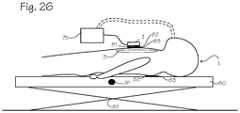
- FIG. 26shows an accelerometer-based compression monitor in place on a patient and a system of reference sensors comprising a reference accelerometer, a switch, and a load sensor disposed such that each sensor may measure various parameters related to chest compressions.
- FIG. 27illustrates a compression waveform that a user feedback system may prompt the rescuer to perform.
- FIG. 28is a block diagram of how an actual chest compression acceleration is converted into a corrupted value for chest position.
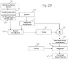
- FIG. 29is a block diagram of a general solution for converting a corrupted chest compression acceleration into an estimated actual depth of chest compressions.
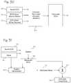
- FIG. 30is a block diagram of how an actual ECG signal is converted into a corrupted ECG signal.
- FIG. 31is a block diagram of a general solution for converting a motion corrupted ECG signal into an estimated actual ECG signal.
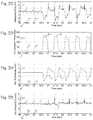
- FIG. 32is a graph of a pig's ECG signal that is corrupted by noise caused by chest compressions.
- FIG. 33is a graph of CPR motion where CPR is performed on a pig.
- FIG. 34is a graph of the pig's estimated ECG noise signal.
- FIG. 35is a graph of the pig's estimated actual ECG signal.
- FIG. 1shows a patient 1 and an accelerometer-based compression monitor 2 in place on the patient.
- An accelerometer-based compression monitoruses one or more accelerometers to determine the depth of compressions.
- An example of an accelerometer-based compression monitormay be found in our own patent, Halperin et al., CPR Chest Compression Monitor, U.S. Pat. No. 6,390,996 (May 21, 2002), which is hereby incorporated by reference in its entirety.
- the compression monitor 2is placed on the sternum 3 of the patient 1 , on the rescuer's hands or arms, or on an automatic CPR device. The chest is then compressed.
- the accelerometermeasures the acceleration of compressions and a processor 4 estimates the actual displacement of the accelerometer based on the measured acceleration.
- the signal processing techniques described belowensure that the estimated actual displacement is accurate and precise.
- the estimated actual displacementmay be provided to a displacement display 5 that provides intelligible feedback to a manual CPR provider or to an automated CPR device.
- CPR-related parametersmay be provided to one or more compression device displays 6 (or other means for user feedback).
- CPR-related parametersinclude the depth of chest compressions, the velocity of chest compressions, the acceleration of chest compressions, and the patient's ECG.
- the compression monitormay be provided with one or more electrodes.
- the processormay process the patient's ECG during compressions to produce an estimated actual ECG.
- the estimated actual ECGmay then be provided to an ECG display 7 (or other means for user feedback) that provides intelligible feedback to the manual CPR provider, to an automated CPR device, or to other individuals or devices that monitor the patient's ECG.
- Actual compression depththe actual depth of a compression at any given time.
- Actual starting point of a compressionthe actual place or point at which a chest compression begins.
- Autoregressive moving averagea function that uses past data samples to modify the current data sample.
- Baseline portion of the compression depth waveformthat portion of depth waveform where the set of actual starting points is most likely to be found.
- Baseline limitera processor or function that operates on the baseline portion of the compression depth waveform.
- Compression Peakthe place or point where maximum compression depth occurs.
- Depth of compressionsthe depth the chest is compressed at any instant in time, where depth is measured relative to the relaxed position of the chest.
- Estimated actual starting point of a compressionthe estimated value of the actual place or point at which a chest compression begins.
- Initial starting point of compressionsthe place or point at which a series of compressions begins.
- Measured starting point of a compressionthe measured value of the place or point at which a chest compression begins.
- Moving averagea function that uses past data samples to modify the current data sample.
- Past starting pointsthe starting points of compressions that have already occurred.
- Peak portion of the compression depth waveformthat portion of depth waveform where the set of actual peaks are most likely to be found.
- Starting point of a compressionthe place or point at which a chest compression is begun.
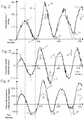
- FIGS. 2 through 4show graphs of compression depth, velocity, and acceleration over time for four hypothetical compressions. No signal processing has been applied to any of waveforms shown in FIGS. 2 through 4 .
- Compression depth in FIG. 2is shown as a positive value—the higher the value, the deeper the chest has been compressed.
- the phantom waveforms 12represent the actual waveforms for compression depth, velocity, and acceleration (measured independently of the accelerometer).
- the solid waveforms 13represents the waveforms derived from the acceleration measured by the compression monitor accelerometer.
- the waveforms 13are also the waveforms reported by the compression monitor to the signal processing system 4 .
- Compression depthis measured in inches, marked at 1 inch intervals
- compression velocityis measured in inches per second (in/s), marked at 1 in/s intervals
- compression accelerationis measured in inches per second per second (in/s2), marked at 1 in/s2 intervals.
- timeis measured in seconds, marked at 1 second intervals.
- the start of compressionsis at time equal to zero.
- the initial depth of compressionsis at depth equal to zero.
- Phantom lines 14 and 15intersect all three graphs. Phantom line 14 corresponds to the time at which maximum compression depth is obtained. Phantom line 15 corresponds to the time at which minimum compression depth is obtained. In addition, phantom line 14 indicates that a compression depth maximum 16 corresponds to a compression velocity of zero. Phantom line 14 also indicates that an acceleration maximum 17 is slightly offset from the compression depth maximum 16. Likewise, phantom line 15 indicates that a compression minimum 18 (or starting point or zero point) corresponds to a compression velocity of zero. Phantom line 15 also indicates that an acceleration minimum 19 is slightly offset from the compression depth minimum 18 . A compression velocity maximum 20 and minimum 21 occur around the middle of a compression.
- the solid waveformsshow the effects of three major types of error: signal error, external acceleration error, and drift.
- Signal erroris primarily represented by the “noisy” (rough) nature of the solid waveforms; however, external acceleration error can also form a portion of the “noise.”
- the acceleration waveformis less noisy, integrating the acceleration increases the effect of the noise in the velocity waveform. Integrating the velocity waveform increases the effect of the noise yet again.
- the compression depth noise FIG. 2is higher than the compression velocity noise in FIG. 3 , which is in turn higher than the compression acceleration noise in FIG. 4 . Accordingly, the compression monitor will report a very noisy compression depth waveform.
- External acceleration erroris primarily represented by the large, positive spike 22 in the solid waveforms of FIGS. 2 through 4 .
- spikescan occur anywhere in the compression cycle and can affect the measured acceleration both positively and negatively.
- the spikeis caused by a large acceleration unrelated to compressions, but nevertheless measured by the accelerometer.
- the actual waveform 12 in all three figuresshows a corresponding peak 23 significantly below spike 22 . Accordingly, absent the correction suggested here, the compression monitor will report for that compression cycle a compression depth much higher than the actual compression depth.
- Driftis primarily represented by the increasing distance between the respective minimums of the actual and reported waveforms of FIGS. 2 through 4 , as shown by arrows 24 and 25 .
- the driftis causing the compression monitor to erroneously report a compression waveform that is becoming increasingly deeper (positive drift).
- the actual waveformis more closely returning to the initial starting point, and is thus the drift shown in FIGS. 2 through 4 is considered a positive drift.
- arrows 24 and 25 in FIGS. 3 and 4illustrate that drift has an increasing affect on the reported velocity and the reported acceleration.
- the effects of driftmean that the initial starting point of compressions cannot be used as a reliable starting point for all compressions. Accordingly, the starting point of compressions must be determined for every compression cycle. In addition, the other sources of noise must be either eliminated or greatly reduced.
- FIG. 5is a flow chart of a signal processing technique that converts a raw acceleration into an estimated actual value for total compression depth.
- the raw acceleration 34is filtered by a first filter in step 35 to produce a filtered acceleration.
- the first filtercomprises a high-pass filter and greatly reduces most forms of signal noise.
- the first filtermay comprise a band pass filter, a moving average filter, an infinite impulse response filter, an autoregressive filter, or an autoregressive moving average filter.
- FIG. 6is a flow chart of an alternate signal processing technique that converts a raw compression acceleration into an estimated actual compression depth. This flowchart is described after the description for FIGS. 7 through 18 .
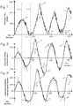
- FIGS. 7 through 9show the graphs of compression depth, velocity, and acceleration over time for four hypothetical compressions after the first filtering step 35 .
- FIGS. 7 through 9show the output of the first filtering step.
- the measured acceleration waveform 13 of FIG. 9is much less noisy than the corresponding unfiltered waveform 13 of FIG. 4 . Since the velocity and depth waveforms of FIGS. 8 and 9 are derived from the acceleration waveform they, too, are less noisy. Nevertheless, the integration process still causes the velocity waveform to be more noisy than the acceleration waveform and the depth waveform to be more noisy than the velocity waveform. In addition, the external acceleration spike 22 still remains, as do the errors caused by drift (as shown by arrows 24 and 25 ).
- the filtered accelerationis integrated in a first integration step 36 to derive the compression velocity.
- the velocityis filtered by a second filter in step 37 to produce a filtered velocity.
- the second filtercomprises a high pass filter and further reduces most signal noise in the velocity and depth waveforms.
- the second filtermay comprise a band pass filter, a moving average filter, an infinite impulse response filter, an autoregressive filter, or an autoregressive moving average filter.
- FIGS. 10 through 12show the graphs of compression depth, velocity, and acceleration over time for four hypothetical compressions after the second filtering step 37 .
- FIGS. 10 through 12show the output of the second filtering step 37 .
- the measured velocity waveform 13 of FIG. 11is less noisy than that of FIG. 8 (the velocity waveform after the first filtering step). Since the depth waveform is derived from the velocity waveform it, too, is correspondingly less noisy. Nevertheless, the integration process still causes the depth waveform to be slightly more noisy than the acceleration and velocity waveforms. In addition, the external acceleration spike 22 still remains, as do the errors caused by drift (as shown by arrows 24 and 25 ).
- the filtered velocityis integrated in a second integration step 38 to calculate the chest compression depth.
- Signal noisehas been substantially eliminated and thus a third filtering step is not required.
- the noise in the depth waveformas shown in FIG. 10
- the noise in the velocity waveformis still slightly more than the noise in the velocity waveform, as shown in FIG. 11 .
- a third filtercomprising a high pass, bandpass, or other filter may be used to further reduce signal noise in the depth waveform.
- a baseline limiterestimates the actual starting point of a compression in step 39 .
- the baseline limiteruses, among other techniques described below, the starting points from past compressions to estimate the current compression starting point.
- the baseline limiteritself comprises a digital or analog signal processor that operates on the baseline portion of the compression depth waveform of FIG. 10 .
- the baseline portion of the compression depth waveformcomprises that portion of depth waveform where the set of actual starting points is most likely to be found.
- the baselinemay comprise the portion of the depth waveform that is equal to and below 1.1 inches compression depth.
- the limiterwill disregard or arbitrarily assign a realistic depth value to any “starting point” above 1.1 inches depth.
- past starting points above the baselineare disregarded and a current starting point above the baseline is reported or treated as an error.
- Past starting pointsare the starting points of compressions that have already occurred.
- a current starting pointis the starting point of the current compression.
- a current starting point above the baselineis assigned a small probability and averaged with the past starting points.
- the baseline limiterestimates the starting point of the current compression by applying a moving average to all starting points that fall within the baseline portion of the depth waveform.
- a moving averageis a function that uses past data samples to modify the current data sample. (Additional moving average techniques are described below.)
- the baseline limitermay weigh recent starting points more heavily than older starting points, meaning that the weight of a given starting point decays over time. Starting points that fall outside the baseline portion of the depth waveform are given an arbitrary weight or no weight.
- the baseline limiterreduces the effect of external acceleration error and drift on the current starting point. In other words, the moving average of all starting points will be statistically closer to the current actual starting point than the current measured starting point derived from the integration of the acceleration.
- each compression starting pointis given a weight of 1.25% of the previous compression starting point.
- the weightingmay comprise a percentage in the range of about 0.1% to about 12.5% (which yields between about 0.3% to about 90% data weighting at the end of about 1 minute).
- the measured value of the current starting point (starting point 1)is weighted 100%
- the most recent starting point (starting point 2)is weighted 98.75%
- the next previous starting point (starting point 3)is weighted 97.5%
- the next previous starting point (starting point 4)is weighted 96.25%, etc. until all compressions are weighted.
- compressions in the distant pastare given no virtually no weight at all.
- the depth of all the weighted starting pointsis then averaged.
- the weighted average of all starting pointsis treated or reported as the current starting point.
- all compressions after a pre-determined time period(such as about 1 minute to about 15 minutes) are disregarded. Thus, only compressions within the last 1 to 15 minutes are averaged. In another embodiment, all compressions after a pre-determined number of compressions (such as about 5 to about 15) are disregarded.
- starting point 10.5 inches
- starting point 21.1 inches
- starting point 34.0 inches
- starting point 40.9 inches
- the baseline limitermay perform other functions to further increase the accuracy and precision of the estimated depth of the current starting point. For example, a probability can be assigned to a given change between the current starting point and the immediate previous starting point. (Likewise a probability can be assigned to a given change between the current starting point and the moving average of all previous starting points.) Large changes in starting point may be given less weight than smaller changes. This technique may be referred to as a “weighted moving average” technique.
- measured depth 1is treated as having a 100% probability of occurring.
- the difference between starting point 2 (1.1 inches) and starting point 4 (0.9 inches)is 0.2 inches, which is assigned a 99% probability.
- this valueis the estimated actual starting point for the current compression.
- a probabilityis assigned to the step size between the depth of the current starting point and the weighted average of all previous starting points.
- the probabilityis assigned to a step size between the current starting point and the immediate past starting point.
- This techniquemay be referred to as a “weighted moving average with memory” technique.
- an autoregressive moving average (ARMA) filtermay be used as the baseline limiter.
- the ARMA filteris an exponentially decaying “forgetting” filter that weights more current data more heavily than past data.
- the ARMAoperates on more than just the compression starting point or peak values.
- the ARMA filteroperates on data samples of compression acceleration, velocity, or depth taken at rapid time intervals. Data samples may be taken at a rate of about 100 samples per second to about 2000 samples per second (with a rate of about 1000 samples per second preferred).
- the ARMA filteroperates on the entire waveform and not just on the compression peaks and the starting points.
- nis the index of the current sample (the “n th ” sample)
- y[n]is the output of the current sample
- x[n]is the input of the current sample
- y[n ⁇ 1]is the output from the previous sample
- ⁇is an independent term that determines how fast the filter “forgets” past outputs and the amount of influence the current input has on the output.
- the value for ⁇may be in the range of about 0.02 to about 0.0002, with a value of about 0.002 being suitable for many CPR-related filter applications.
- the high pass filtermay be used to eliminate low-frequency variations in the depth, velocity, or acceleration signals.
- the moving average techniques in the above exampleshave been described in the context of processing the compression depth waveform. However, the techniques can be used to process the velocity waveform and the acceleration waveform, should it be desired to report accurate values for the velocity and acceleration of compressions.
- the moving average techniquesmay be applied to each waveform separately. In other words, one does not necessarily apply a moving average technique to the acceleration waveform, then integrate the acceleration waveform, then apply a second moving average technique to the velocity waveform, then integrate the velocity waveform, and finally apply a third moving average technique to the depth waveform. However, in other embodiments this procedure may be used.
- baseline limitercomprises a signal processor that uses a transition probability map to identify the probability of particular shifts in the measured starting point.
- the probability mapmay be pre-determined, such as by using a density estimator or kernel estimator, and then hard-coded into the compression monitor software.
- a particular starting point measurementis compared to the probability map and the system determines by how much a given shift in the measured starting point is erroneous. The reported starting point is adjusted accordingly.
- a transition probability mapmay be used to estimate the actual peak and also the actual maximum depth for each compression.
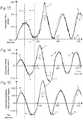
- FIGS. 13 through 15show the graphs of compression depth, velocity, and acceleration over time for four hypothetical compressions.
- FIGS. 13 through 15also show the output of steps 35 through 39 in FIG. 5 .
- the baseline limiterhas been applied separately to the velocity waveform ( FIG. 14 ) in step 47 and to the acceleration waveform ( FIG. 15 ) in step 48 .
- FIGS. 13 through 15show that a moving average technique reduces the effect of drift in the reported starting point of each compression.
- the moving average techniquesalso reduce the effect of external acceleration errors that appear in the baseline portion of the waveform.
- the reported starting pointswere becoming increasingly deeper, though the actual starting points were returning to close to the actual initial starting point.
- the compression monitorwill report an estimated actual compression depth that is closer to the actual compression depth.
- Arrows 49 and 50which are shorter than arrows 24 and 25 in FIGS. 2 through 4 and FIGS. 7 through 12 , show the beneficial effect of applying a moving average technique to each waveform.
- the compression depth waveform corrected by the baseline limitermay be passed through a third filter in step 51 to reduce any accumulated signal noise in the compression depth waveform.
- the third filtercomprises a high pass filter, though in other embodiments the third filter may comprise a band pass filter.
- the depth waveform(whether filtered or unfiltered) is provided to a starting point detector in step 52 .
- the starting point detectoridentifies the value of the current estimated starting point.
- the current estimated starting pointis then provided to a means for combining signals 53 (as indicated by line 54 ).
- the means for combining signals 53will later use the current estimated starting point to calculate the estimated actual compression depth.
- the means for combining signalscomprises a signal adder, a linear system model, a non-linear system model, or other means for combining signals.
- the compression waveformmay be provided to a peak limiter in step 55 .
- the peak limiteris a signal processor that performs similar functions to the baseline limiter, but instead operates on the peak portion of a compression waveform.
- the peak portion of the waveformcomprises that portion of the waveform in which a peak is most likely to occur.
- the peak portionis the portion of the waveform above the baseline portion.
- the peak portion of the depth waveformwould be the portion of the depth waveform that is above 1.1 inches.
- the peak limiterthus will smooth the peak portion of a waveform in much the same way as the baseline limiter smoothes the baseline portion of a waveform.
- the peak limitersets an outside boundary on the size of the maximum compression depth.
- the peak limitereither disregards (throws out) or sets an arbitrary value to any peak that is greater than a known, improbable peak value (the depth of a large person's chest, for example, would not be a probable value for CPR compression depth).
- the peak limiterprevents the compression monitor from reporting a compression depth that is improbable.
- FIGS. 16 through 18show the graphs of compression depth, velocity, and acceleration over time for four hypothetical compressions after the peak limiter step 55 in FIG. 5 .
- FIGS. 16 through 18show the output of steps 35 through 55 ).
- a peak limiterhas been applied separately to the velocity waveform in step 56 and to the acceleration waveform in step 57 .
- the effect of the external acceleration spike 22has been greatly reduced. Combined with the techniques discussed in the previous processing steps, the reported waveforms are now close to the actual waveforms.
- the estimated peakmay optionally be provided to a fourth filter 58 to remove remaining signal noise.
- the fourth filtercomprises a high pass filter, though in other embodiments the fourth filter may comprise a band pass or other filter.
- the depth waveformis provided to a peak detector in step 59 .
- the peak detectoridentifies the value of the estimated peak (the estimated maximum depth of the current compression).
- the estimated peakis then provided to the means for combining signals 53 .
- the means for combining signals 53combines the estimated starting point 52 with the estimated peak 59 to produce an estimated actual compression depth for the current compression 61 .
- the estimated actual depthis then provided to a means for user feedback 62 (a user feedback system).
- the means for user feedbackmay comprise a speaker, a visual display, one or more LEDs, a vibrator, radio, or other means for communicating with the rescuer.
- the user feedback systemin turn provides information corresponding to the estimated actual depth of the current compression to the rescuer.
- the baseline portion and the peak portiondo not overlap.
- the compression depth waveformmay be thought of as comprising two portions, the baseline portion and the peak portion.
- Each portion of the depth waveformis treated differently by two different procedures (the baseline limiter and the peak limiter) to extract different information.
- both the baseline limiter and the peak limiteroperate on the same depth waveform. The effect of this is that the signal comprising the depth waveform is provided first to the baseline limiter and then to the peak limiter (the signal is not split).
- the technique shown in FIG. 6may be used when the baseline portion and the peak portion overlap (though the technique may also be used when the baseline portion and peak portion do not overlap).
- the technique of FIG. 6may be used when the baseline portion is set below 1.5 inches (relative to the chest's relaxed position) and the peak portion is set above 1.0 inches (relative to the chest's relaxed position).
- the signal representing the depth waveformis split and is provided to two separate processors, a baseline limiter and a peak limiter. Each processor performs similar functions to the limiters already described.
- the baseline limiter and the peak limiteract independently of each other, the technique of FIG. 6 produces an estimated starting point and an estimated peak in much the same was as the technique shown in FIG. 5 .
- the means for combining signalsthen combines the estimated starting point and estimated peak in step 53 to produce the estimated actual depth of the current compression.
- the estimated actual depth of the current compressionis provided to the user feedback system in step 62 .
- the user feedback systemin turn provides the estimated actual depth of the current compression to the rescuer.
- FIG. 19is a flow chart of a signal processing technique that uses a change in ECG noise 63 to activate a switch 64 that, in turn, controls when an accelerometer begins to measure acceleration.
- the compression monitoris provided with one or more electrodes, or some other means for measuring the patient's ECG.
- the rescuerperforms compressions the patient's ECG becomes noisy. Even if the patient's actual ECG is flat (shows no activity) the reported ECG will still show the noise caused by chest compressions. Indeed, a motion artifact signal (an ECG noise component caused by chest compressions) will be superimposed on any ECG rhythm. Whatever the actual ECG rhythm, the ECG noise may be isolated and accounted for.
- the starting point of a compressionmay be correlated to the point where the ECG noise exceeds a pre-determined threshold.
- the time lagis on the order of milliseconds to tenths of a second.
- a buffereither digital or analog
- the switchis programmed to activate the accelerometer (which will begin to take acceleration measurements). Total compression depth is then determined by double integrating the measured acceleration.
- FIGS. 20 through 25show compression depth, velocity, and acceleration over time for four hypothetical compressions.
- the phantom waveforms 12represent the actual waveforms for compression depth, velocity, and acceleration (measured independently of the accelerometer).
- the solid waveforms 13represent the waveforms derived from the acceleration measured by the accelerometer.
- the solid waveformsare also the waveforms reported by the compression monitor.
- the effects of signal noiseare shown by the rough nature of the solid waveforms.
- the effects of external acceleration noiseare shown by the two spikes, 65 and 66 , in the reported waveform.
- the effects of negative drift (increasingly shallow compressions)are shown by the increasing distance (represented by arrows 67 and 68 ) between the minimums in the reported and the actual waveforms.
- FIGS. 23 through 25show graphs of compression depth, velocity, and acceleration over time for hypothetical compressions.
- ECG noiseas a reference sensor reduces certain external acceleration errors and reduces the effect of negative drift.
- the ECG noise reference sensorcan also reduce the effect of positive drift).
- the ECG noise reference sensorreduces the effect of external acceleration noise that occurs near a compression minimum. Since the accelerometer is not “on,” a portion of the external acceleration spike is “ignored”. In practice the accelerometer is still taking data, but software or hardware is used to process out accelerometer data or signals that occur during a time period where ECG noise does not reach a predetermined level.
- the estimated actual depth of compressionsis calculated when the ECG noise falls within a predetermined threshold.
- the effect of spike 65is reduced in the reported waveform.
- the accelerometerby itself still cannot tell the difference between a compression-related acceleration and an external acceleration.
- the reported waveformis still subject to external acceleration noise that occurs during a compression, as shown by spike 66 .
- the ECG noise reference sensordoes reduce the effects of drift. Since the starting point of a compression is independently established, the waveform is much less subject to either positive or negative drift. In other words, the accelerometer will always measure acceleration after the actual start of compressions. Thus, the reported waveform of FIG. 23 more accurately shows what the rescuer is actually doing—compressing the chest from starting points that are becoming increasingly deep. Thus, peaks 69 and 70 show that the measured waveform more closely matches the actual waveform.
- FIGS. 23 through 25still show the same levels of signal noise as shown in FIGS. 20 through 22 .
- the ECG noise reference sensormay be combined with the signal processing techniques of FIG. 5 or 6 . The combined techniques will produce a reported depth waveform that is close to the actual waveform.
- FIG. 26shows an accelerometer-based compression monitor in place on a patient 1 who is lying on a surface 80 .
- a system of reference sensorscomprising an accelerometer 81 , a load sensor 82 , and a switch 83 are disposed such that each sensor may measure various parameters related to chest compressions.
- the reference accelerometersmay be disposed elsewhere on the patient, or upon any reference object that experiences the same external accelerations the patient experiences.
- the reference accelerometersmay comprise a three-axis accelerometer, but may also comprise three orthogonal single-axis accelerometers or one single axis accelerometer (in which case the accelerations along the other two axes are assumed to be negligible).
- the reference accelerometers 81allow a signal processor to eliminate external acceleration error, such as those accelerations caused by transporting the patient.
- the acceleration sensed by the compression monitor or automatic CPR device(the device acceleration) is provided to a signal processor.
- the device accelerationcontains the acceleration caused by compressions (the compression acceleration) and the acceleration caused by the external accelerations (the external acceleration).
- the reference accelerometer or accelerometersprovide a reference acceleration to the signal processor.
- the reference accelerationcontains only the external acceleration of the patient.
- the reference accelerationis combined with the device acceleration to produce an estimated actual acceleration. (The effect of compression accelerations on the reference acceleration is negligible since the surface and patient are kept steady with respect to the compression monitor.)
- the estimated actual accelerationmay be double integrated to produce an estimated actual chest depth.
- the depth of compressionsmay be determined even in the presence of large external accelerations.
- the position signalmay be made more accurate and precise by combining the actual acceleration with the signal processing technique of FIG. 5 or 6 , or with other signal processing techniques.
- Reference sensorsmay comprise a load sensor 82 , a switch 83 , a transthoracic impedance detector, an ECG noise detector (as described above), a voltage or current sensor in an automatic CPR device, a start signal in an automatic CPR device, an encoder in an automatic CPR device, or any other sensor capable of independently detecting the actual beginning of a compression.
- the reference sensordetects the beginning of a compression then the starting point is set to zero.
- the accelerationis then processed to derive compression depth.
- the technique of setting the starting point to zero when a reference sensor detects the beginning of a compressionmay also be combined with the signal processing techniques of FIG. 5 or 6 .
- the switchis disposed such that when a compression begins the switch will be closed.
- the switchmay be disposed beneath or on the compression monitor, on the patient 1 , on the surface 80 upon which the patient lies, on the rescuer's hand, on a CPR machine, on the patient, or on some other location that allows the switch to register that a compression has begun.
- the switchmay comprise many different types of switches and sensors, including a contact switch, a motion sensor, a voltage sensor on an automatic CPR device, an optical, rotary, or other encoder on an automatic CPR device, the displacement of a shaft or other component on an automatic CPR device, a potentiometer, a strain gage, a piezoresistive transducer, a differential transformer, synchro and induction potentiometers, variable-inductance and variable-reluctance pickups, an eddy current non-conducting transducer, a capacitive transducer, an electro-optical transducer, a photographic switch, a video tape switch, a holographic switch, a switch that uses photoelastic techniques, translation encoders, an ultrasonic transducer, moving coil and moving magnet pickups, an AC or DC tachometer, an eddy-current drag-cup tachometer, additional accelerometers, or a gyroscopic displacement switch.
- a contact switchincluding a motion sensor
- the load sensormay be operatively connected to the rescuer, the patient, an automatic CPR device, beneath the patient, or elsewhere so long as the load sensor senses a load when compressions begin.
- the load sensormeasures a load that exceeds a pre-determined threshold, then the measured starting point is set to zero.
- the load sensormay also be operatively connected to a switch, which activates when the load sensor senses a load, or the load sensor may merely provide input to a signal processor system identifier (described in more detail below). Compression depth is then determined by integrating the acceleration twice.
- the technique of setting the starting point to zero when a load sensor detects the beginning of a compressionmay also be combined with the signal processing techniques of FIG. 5 or 6 .
- the load sensormay be disposed such that the sensor can sense both the weight of the patient and the force of compressions.
- the load sensor 82may be disposed beneath the surface 80 upon which the patient 1 rests. During compressions the force of pressing on the patient causes the load sensor to report a total force greater than the patient's weight. Accordingly, a starting point is set to zero when the total force is about equal to the patient's weight.
- Examples of force sensors that can be used with this techniqueinclude pressure sensors, elastic force transducers, shaft displacement on an automatic CPR device, a voltage or a current sensor on an automatic CPR device, an optical, rotary, or other encoder on an automatic CPR device, bonded strain gages, beam strain gages, differential transformers, piezoelectric transducers, variable reluctance/FM oscillators, gyroscopic force transducers, and vibrating wire force detectors.
- Examples of pressure sensors that can be used with this techniqueinclude deadweight gages, manometers, elastic transducers, piezoelectric transducers, and force-balance transducers.
- one or more ECG, defibrillation, or other electrodesare disposed on the patient's thorax.
- the thoracic impedancecomprises the impedance due to skin and thoracic contents between any two electrodes.
- the change in thoracic impedancemay be measured by a small test current or by any other means for measuring impedance.
- the impedance changes by a pre-determined amountthen the starting point is set to zero. Total compression depth may then be determined by processing the measured acceleration.
- FIG. 27shows a compression waveform that the compression monitor may prompt the rescuer to perform. Depth is measured in inches and time is measured in seconds. The scale shown in FIG. 27 is marked in 0.5 second intervals and 1.0 inch intervals respectively.
- the compression phase of the cycleis indicated by the positively sloped curve 84 .
- the compression phase of the cycleends at the maximum compression depth 85 (compression peak).
- the decompression phase of the cycleis indicated by the negatively sloped curve 86 .
- the compression waveformincludes a compression hold 89 , where the rescuer maintains a hold at maximum compression depth for a short period of time, and an incomplete decompression hold 90 , where the rescuer maintains a short hold at a point deeper than the initial starting point.
- Each compression and decompressionis performed quickly, at high acceleration and velocity, as indicated by the relatively steep slopes of the compression phase 84 and the decompression phase 86 .
- the duty cycleis slightly less than 50% (the ratio of compression and decompression time is 1), meaning that slightly less time is spent in the compression phase, as indicated by the distance between arrows 89 , than in the decompression phase, as indicated by the distance between arrows 90 .
- the compression waveform of FIG. 27shows an example of a particular waveform that the compression monitor can instruct a rescuer to perform
- another waveformmay lack a compression hold phase.
- the exact waveformdepends on the current state of the art of what kind of compression waveform comprises an optimal compression waveform for a particular kind of patient.
- the compression monitormay be provided with a switch, button, software, or other means for user input which allows the rescuer to enter the size or shape of the patient.
- the compression monitormay use this information to choose a particular waveform from a library of waveforms.
- the compression waveformsare thus adaptable to findings in future research, AHA guidelines, rescuer observations, and medical professional preferences. Accordingly, at various times different waveforms may be provided to the user feedback system, as described more fully below.
- the prompted waveformmay be provided by the user feedback system (step 62 in FIG. 5 ).
- the user feedback systemmay provide the rescuer or automatic CPR device with other compression-related information.
- the user feedback systemmay display information regarding the starting point of compressions, the compression depth waveform, the compression velocity waveform, and the compression acceleration waveform.
- the user feedback systemmay provide the rescuer or the automatic CPR device with all of the data needed to continuously track the position, velocity, and acceleration of the chest during all phases of CPR. This information may be used to evaluate the performance of a rescuer or automatic CPR device.
- the user feedback systemmay also provide a rescuer or automatic CPR device with information concerning the compression phase quality and the decompression phase quality.
- Compression phase qualityis the quality of compressions with respect to total compression depth, the duty cycle, the acceleration of compressions, smoothness of compressions, and other factors related to the compression phase.
- Decompression phase qualityis the quality of compressions with respect to whether the rescuer returns to the actual initial position, the duty cycle, the acceleration of decompressions, the smoothness of decompressions, and other factors related to the decompression phase.
- the rescuer or automatic CPR devicemay use this information to evaluate or prompt the kind and quality of compressions.
- the user feedback system 62may provide the rescuer or automatic CPR device with information concerning compression phase quality by combining information gained from the acceleration, velocity, and position waveforms. For example, the user feedback system can instruct the rescuer to increase compression force when the depth of compressions are less than recommended guidelines and to reduce compression force when the depth of compressions are greater than recommended guidelines.
- the user feedback systemmay also instruct the rescuer with regard to other compression phase parameters of a compression waveform.
- the user feedback systemcan inform the rescuer or automatic CPR device if the time to achieve proper compression depth is too short or too long.
- the user feedback system 62may also provide the rescuer or automatic CPR device with information regarding decompression phase quality by combining information gained from the acceleration, velocity, and position waveforms.
- the user feedback systemcan instruct the user or device on the proper position at which to rest after a decompression.
- the feedback systemcan instruct the user or device to allow the chest to fully relax if the rescuer or device is not allowing the chest to fully return to its initial starting position.
- the user feedback systemcan instruct the user or the device to return to a depth just below the initial chest position. In this case, the rescuer or device implements a “decompression hold” and maintains force on the chest even when the compression cycle reaches its minimum depth.
- the feedback systemcan indicate different compression starting points at different times.
- the user feedback systemcan instruct the rescuer or device to apply incomplete decompression holds during compression cycles, but to allow the chest to return to its fully relaxed position during ventilation pauses.
- the user feedback systemmay also instruct the rescuer or device with regard to other decompression phase parameters, such as the decompression rate and the duty cycle of the decompression phase.
- the information gained from the compression phase quality and the decompression phase qualityenable the user feedback system to prompt the rescuer on how to perform an optimum compression waveform and an optimum compression duty cycle.
- a rescuerperforms a particular compression waveform by performing compressions at a pre-determined depth and rate, and by holding the chest at a pre-determined compression depth for a pre-determined time.
- a rescuerperforms a particular duty cycle by compressing the chest for a pre-determined period and allowing the chest to relax for another pre-determined period.
- the user feedback systemcan prompt the rescuer or automatic CPR device to perform at the appropriate compression rate, compression depth, compression velocity (the time required to compress or decompress the patient), compression acceleration, and compression hold time for each phase (compression and decompression) of the compression cycle.
- the compression waveform that the rescuer or device actually appliescan conform to a complex compression waveform. Since research has shown that most patients benefit from more complex waveforms, patient survival is likely to increase if the rescuer or automatic CPR device uses a compression monitor with this user feedback system.
- the user feedback system 62 of FIG. 5can provide the rescuer or CPR device with feedback regarding the compression duty cycle.
- the duty cycleis the ratio of time under compression to the time under decompression for each compression cycle. (However, the duty cycle does not include time periods where no compressions are taking place, such as during ventilation.) If the duty cycle does not fall within pre-determined parameters, then the user feedback system may prompt the rescuer to adjust compression timing and compression rate in order to effect an optimal duty cycle.
- the user feedback system described abovecomprises the last step in a particular solution to the problem of determining an accurate value for chest displacement from a raw acceleration signal.
- FIG. 5is the flowchart for this solution. Many variations of that solution exist, as already described, though it is possible to view the problem from a general perspective and to create a general solution.
- FIGS. 28 and 29are block diagrams that represent the general problem to and the general solution for determining an accurate position from an acceleration measured during CPR.
- FIG. 28is a block diagram of how an actual chest compression acceleration is converted into a corrupted value for chest position.
- the actual acceleration 105 , signal noise 106 , external acceleration noise 107 , and some forms of drift 108are combined by an unknown function 109 (which may be linear or non-linear and may include random or deterministic inputs).
- the unknown non-linear functionis known as the system, which produces the corrupted acceleration 110 measured by the accelerometer.
- the corrupted accelerationis then integrated twice, which greatly compounds the problem introduced by the corruption in the acceleration.
- the increased erroris referred to as integration error 111 (although it is assumed that the integration technique itself does not directly contribute errors into the position).
- additional sources of drift 112can affect the final value for the corrupted position 113 .
- FIG. 29is a block diagram of a general solution for converting a corrupted chest compression acceleration into an estimated actual depth of chest compressions.
- a reference sensor 119may establish the actual starting point of a compression. Thus, the starting point of the acceleration will be known. (Although helpful, the reference sensor 119 is not necessary to the general solution).
- the actual acceleration 105 and the real or the estimated noise sources 120(which comprise blocks 106 through 108 of FIG. 28 ) are combined by the system 109 by an unknown function.
- the resultis the corrupted acceleration 110 .
- the measured accelerationis then provided to a means for combining data 121 (which may comprise a linear or a non-linear function) and to a system identifier 122 .
- the system identifiercomprises one or more functions (either linear or non-linear) that model the system.
- One or more noise references that can be correlated to the noise sources 120may also be provided to the system identification function 122 .
- noise identified by a low frequency filtercan be correlated to signal noise or a reference accelerometer can be correlated to the external acceleration noise.
- the system identification functionmay also use various parameters of an automatic CPR device as noise source references, even if the reference itself does not produce noise in the acceleration.
- the noise source referencemust somehow be correlated to a source of noise in the acceleration signal.
- the accelerometer-based depth measurementreports a chest depth of 0.5 inches.
- a simultaneous current spike in the automatic CPR deviceinforms the system that the CPR device is compressing the chest much harder than should be required to achieve a chest depth of 0.5 inches.
- the discrepancymay be caused by external acceleration noise or by drift.
- the current spikemay be correlated to a source of noise in the system.
- This informationmay be used by the system identifier to help model the system.
- voltage, shaft displacement, or optical or rotary encodersmay be used as references by the system identifier to help model the system. (Again, the noise references are useful but not necessary).
- the system identifierthen combines or correlates the noise source references and the measured acceleration in order to produce the estimated noise 123 in the measured acceleration.
- the estimated noise 123is then provided to the means for combining data 121 .
- the means for combining datacombines the estimated noise 123 and the measured acceleration 110 to produce an estimated actual acceleration 124 .
- the estimated actual accelerationis then integrated 125 twice. Filters 126 may optionally be used during one or both integration steps to reduce the compounding effect of errors that may still linger in the estimated actual acceleration. The final result is an accurate and precise estimate of the actual position 127 of the accelerometer.
- the system identification function 122models the system and thus can be used to estimate the noise in the acceleration. (Once the noise is known it can be easily eliminated by combining the noisy acceleration with the measured acceleration.) In other words, system identification is the process of using the input and output data to model the function that combines the actual acceleration and the sources of noise in the acceleration.
- the system identification problemhas a known or measured output and an input that may be known or unknown. The addition of known or measured input is beneficial to system identification, but not necessary.
- the system itselfis an unknown arbitrary function that can be linear or non-linear, though some boundary conditions may be known.
- a number of methodsmay be used to model the system. Each of these methods may comprise, alone or in combination, the system identification function in step 122 . These methods may operate by taking many data samples per second, as opposed to operating only on the compression starting points or peak points. Nevertheless, these methods may also be performed on the compression starting points or the compression peaks.
- a partial list of these methodsinclude: autoregression, autoregression with extra inputs, autoregressive moving average (which is one of the methods used in the techniques shown in FIGS.
- autoregressive moving average with extra inputsautoregressive integrated moving average, autoregressive integrated moving average with extra inputs, a Box-Jenkins model, an output error model, a hidden Markov model, a Fourier transform, a wavelet transform, wavelet de-noising, wavelet filtering, adaptive neural networks, recurrent neural networks, radial basis function nets, adaptive curve fitting (splines), Kalman filters, extended Kalman filters, adaptive Kalman filters, unscented Kalman filters, and kernel estimation.
- Algorithmic approaches that may be used to find the system identification functioninclude maximum entropy, maximum likelihood, recursive least squares (or similar techniques), numerical methods, unconstrained global search or optimization, expectation minimization, and fast Fourier transforms.
- Equations (1) and (2)may be simplified into equations (3) and (4):
- ⁇ and ⁇are small numbers that reflect the relative amount of information provided by the latest time step.
- Qis a function that relates inputs, outputs, and states. Equations (3) and (4) are more simple in the sense that it is more simple to compute the equations by recursive than equations (1) and (2).
- a number of numerical algorithmsmay be used to solve equations (3) and (4).
- a partial list of numerical algorithmsinclude recursive least squares, recursive (or recursion) instrumental variables, recursive prediction error methods, recursive pseudolinear regression, recursive Kalman filters (including time varying parameters), and recursive Kalman filters for time varying systems.
- These numerical techniquesencompass many of the famous “named” techniques as special cases, including a Kalman filter, an extended Kalman filter, extended recursive least squares, and others.
- Each algorithmhas strengths and weaknesses, but all asymptotically approach a solution to equations (3) and (4).
- L(t), P(t), and P(t ⁇ 1)are terms used to simplify the equation, ⁇ (t) is a regression vector, ⁇ (t) is a forgetting factor (described in more detail below), and ⁇ T (t) is the transpose of the regression vector.
- equation 4can also be expressed for the cases of recursive instrumental variables, recursive prediction-error methods, recursive pseudolinear regression, a recursive Kalman filter for time-varying systems, and a recursive Kalman filter with parametric variation.
- additional parametersinclude data weighting, choice of updating step, choice of updating gain, and model order selection.
- data weightingwhen a system is time-varying the input-output data near the present time more accurately reflects the nature of the present system. Data recorded further back in time is more closely related to a past system state. To reflect this fact the data can be weighted to favor a more recent system state. Actual data weighting is accomplished by the “forgetting factor,” ⁇ , in equations 5 through 5b. The selection of ⁇ is made based on information about how fast the system changes state. A typical range for ⁇ is between about 0.9800 and about 0.9999 (though ⁇ may be 1.0000 if no “forgetting factor” is desired).
- T 0The sample number at which a data sample has a weight of about 36%, known as T 0 , may be mathematically expressed as:
- T 01 1 - ⁇ .
- T 0(and hence ⁇ ) is selected with appropriate knowledge of the system state and can be used to tune system identification so that the estimated actual acceleration most closely approximates the actual acceleration if the actual acceleration were independently measured.
- T 0is pre-set before the compression monitor begins taking measurements.
- ⁇1 the more samples are needed to reach the point where a given data sample is given a weight of about 36%.
- ⁇can vary with time so that the system identifier may adapt to changing situations. For example, ⁇ may vary during a ventilation pause and in one embodiment ⁇ increases during a ventilation pause. The effect of increasing ⁇ during ventilation pauses is to discard data points very quickly. Thus, the compression monitor will not report a change in compression depth during a ventilation pause.
- the choice of updating stepaffects the quality of the model.
- the update stepcan be implemented using a variety of methods. Some system identifiers may be solved analytically, such as the Kalman filter, and the updating step may be solved analytically. Other system identifiers must be solved numerically.
- Three updating methods that may be used when a numerical solution is requiredare a Gauss-Newton update, a gradient update, and a Levenberg-Marquardt update.
- the Gauss-Newton updateconverges to an accurate fit of the actual solution, though it requires a large number of steps (and thus more computation time).
- the gradient updateconverges quickly but does not converge as accurately to the actual solution as the Gauss-Newton update.
- the methodsmay be combined.
- the gradient updateis used first to converge the fit quickly and then the identifier switches to the Gauss-Newton update to achieve the final fit. This combined technique is known as a Levenberg-Marquardt update.
- 2R ( t ⁇ a )+ ⁇ ( t )[ I
- R(t)is the Hessian of the identification criterion
- R(t ⁇ 1)is the Hessian of the identification criterion in the previous time step
- ⁇ (t)is the updating gain (which is related to the forgetting factor)
- ⁇ (t)is the regression vector.
- the choice of updating gainis another step that is used in many recursive system identification functions.
- the updating gainis related to the forgetting factor.
- model order selectionthe recursive system identification techniques fit a system model to input-output data.
- the structure of that modelmust be determined before the recursive.
- the standard way of solving the model structure problemis to solve a wide range of model structures and then select which model fits the data best.
- a simple measure of model fitlike the mean squared error, tends to over-estimate the model order and fit to the process or measurement noise. If a model is under-estimated, critical components of the system might be missed.
- measures of model fit, or metricsare evaluated over a range of model orders. The model order is the number of terms used in the model. The smallest model order that minimizes the fit is the appropriate model.
- FPEfinal prediction error
- AICAkaike's information criterion
- AICmaximum description length
- statistical hypothesis testingsuch as the student's t-test
- V( 1 + d / N ) ( 1 - d / N ) , ( 11 )
- Vis the quadratic loss function
- dis the size of the model order
- Nis the number of data points.
- the quadratic loss functionmay be any quadratic function that relates the additional cost function of using additional terms.
- FIG. 30is a block diagram illustrating the problem of ECG noise caused by CPR and other sources of noise. Stated differently, FIG. 30 is a block diagram of how a theoretical actual ECG signal 135 and the noise sources are combined to produce the measured ECG (which contains the motion corrupting artifact).
- the ECG noisecomprising ECG noise due to compressions 136 and other sources of noise 137 , are combined with the actual ECG by an unknown linear or non-linear function known as the system 138 .
- the primary source of noise in the ECGis due to the motion of compressions, though other sources of noise exist and may be accounted for by the solution presented below.
- the systemproduces a corrupted ECG 139 which, if left unprocessed, cannot be used to accurately report the electrical activity of the patient's heart.
- the systemcombines the ECG noise and the actual ECG in a way that causes the ECG noise to overlap the actual ECG in the frequency domain.
- a simple bandpass filteris insufficient to accurately process the corrupted ECG. (A simple bandpass filter will eliminate important components of the actual ECG as well as eliminating the ECG noise).
- FIG. 31is a block diagram of a general solution to the problem illustrated in FIG. 30 and illustrates the process of converting a motion corrupted ECG signal into an estimated actual ECG signal.
- the system 138combines the actual ECG 135 and the ECG noise 136 to produce the corrupted ECG 139 that is measured by an observer.
- the measured ECG 139 and a reference corresponding to the ECG noise 136are provided to a system identifier 140 .
- a signal corresponding to CPR induced motionmay be provided to the system identifier.
- a force transducermay be disposed on a compression monitor (or on the patient or rescuer) such that the force transducer measures force during a compression.
- a signal corresponding to the forceis provided to the system identifier as a reference signal.
- Other signals corresponding to CPR induced motionmay comprise various parameters of an automatic CPR device. For example, a signal correlating to the displacement of a drive shaft or other component can be correlated to the CPR motion, a signal corresponding to the change in current or voltage required to drive the device can be correlated to the CPR motion, or signals produced by optical or rotary encoders may be correlated to the CPR motion.
- the systemidentifier models the system and then estimates the noise component of the measured ECG signal (the estimated noise 141 ).
- the estimated ECG noise 141 and the measured ECG 139are then provided to a means for combining signals 142 , which combines the ECG noise and the measured ECG to produce the estimated actual ECG 143 . Since the estimated actual ECG is produced during compressions, the signal processing method allows the ECG sensor to detect the heart's normal sinus rhythm even during compressions. Thus, there is no need to periodically pause compressions to check for the existence of a pulse. As a result, the overall quality of CPR increases and the patient is more likely to survive.
- the system identifier 140may comprise similar kinds of functions and methods as described in the context of the signal processing methods of FIG. 29 .
- the recursive least squares method described in the context of FIG. 29may be used to identify the noise component of the measured ECG signal.
- FIGS. 32 through 35show the effect of using the method of FIG. 31 to estimate a pig's actual ECG when the ECG is measured during chest compressions.
- each time marker 150 along time scale 151corresponds to the same time marker in the other three graphs, thus making possible a direct comparison of one graph to each of the other graphs.
- the voltage scales 152 of FIGS. 32, 34, and 35are slightly different from each other.
- FIG. 32is a graph (millivolts versus milliseconds) of an actual pig's ECG signal that is corrupted by noise caused by chest compressions.
- FIG. 32represents the ECG measured during compressions without signal processing.
- FIG. 33is a graph of force versus time for an actual CPR motion signal.
- the motion signalcomprises a time varying force signal and corresponds to the force a CPR device places on the pig's chest while performing chest compressions.
- the force peaks 153correspond to the maximum depth of compressions.
- the motion signalcould comprise a time varying force signal that corresponds to the force placed on the patient's chest while a rescuer or automatic CPR device performs chest compressions.
- a force transducer disposed on a compression monitor(such as on the back of the compression monitor) measures the force of compressions and produces the force signal.
- the force signalis later correlated to the ECG noise.
- the force transducer or other force sensormay also be disposed under the patient's back and then operably connected to the compression monitor.
- FIG. 34is a graph of voltage versus time for the estimated ECG noise signal caused by the chest compressions shown in FIG. 33 .
- a comparison of FIGS. 33 and 34shows that the time varying pressure signal corresponds directly to incidence of ECG noise.
- the pressure peaks 153 caused by chest compressionscorrespond to the incidence of noise peaks 154 .
- the system identifier 140 used to generate the estimated noise component of the noisy ECGcomprises a recursive least squares method as described in the context of FIG. 29 .
- the autoregressive orderwas selected to be equal to 1.
- the moving average orderwas selected to be 10.
- the autoregressive orderwas selected to be 10.
- the derivative orderwas also selected to be 0. (The derivative order is a linear or non-linear term used in the system model; specifically it may be either a truncated positive derivative or a truncated negative derivative.
- the non-linear termsare extensions of the recursive least squares model fit algorithm).
- the forgetting factor, ⁇was selected to be 1.0000.
- FIG. 35is a graph of the pig's estimated actual ECG signal.
- the graph of FIG. 35is generated by subtracting the estimated noise signal of FIG. 34 from the measured ECG signal of FIG. 32 .
- the estimated actual ECG signalcorresponds closely to the pig's actual ECG signal.
- the signal processing methods described in the context of noisy ECG signals ( FIGS. 30 and 31 ) and noisy acceleration signals ( FIGS. 28 and 29 ), as well as the techniques described in relation to the baseline limiter and the peak limiter,may also be used to estimate the actual value of the patient's transthoracic impedance (the chest's electrical resistance or impedance).
- the estimated actual value of the patient's transthoracic impedancemay be used to determine the amount of voltage needed to shock the patient with a defibrillator.
- the measured value of the transthoracic impedancebecomes noisy.
- the general signal processing solutions and the limiters already describedmay be used to identify, isolate, and eliminate the noise component of the measured transthoracic impedance.
- the actual value of the transthoracic impedancemay be estimated.
- the estimated actual value of the transthoracic impedancemay be provided to a means for defibrillating the patient.
- the means for defibrillating the patientuses the estimated actual value of the transthoracic impedance to determine the exact voltage necessary to apply an effective shock to the patient. Since the exact value of the voltage required is also known, the defibrillator can be used efficiently (thus preserving battery life and making the device safer).
- an automated CPR device equipped with an AEDmay perform defibrillation shocks to a patient without stopping compressions.
- the devicemay determine when defibrillation is appropriate based on the estimated actual ECG and may apply the appropriate defibrillation voltage based on the estimated actual transthoracic impedance. Since compressions do not stop during defibrillation, the patient's blood flow does not stop (meaning the patient is more likely to survive).
- the compression monitor using these signal processing techniquesmay be used with any means for compressing the chest of the patient.
- a means for compressing the chestmay comprise manual CPR, electro-stimulation, a means for performing automatic CPR (including belts, straps, pistons, and plates that are driven by motors or manual levers), or other devices suitable for compressing the chest.
- automatic CPR devicesmay be found in our own patent Sherman et al., Modular CPR Assist Device, U.S. Pat. No. 6,066,106 (May 23, 2000) and in our application CPR Assist Device with Pressure Bladder Feedback, U.S. application Ser. No. 09/866,377 filed May 25, 2001.
- the accelerometeritself may be disposed in any location where the accelerometer experiences the downward or upward acceleration of compressions.
- the accelerometermay be disposed within or otherwise disposed on the means for compressing the chest, such as a compression belt.
- the compression monitormay be disposed beneath a rescuer's hands while the rescuer performs compressions, or the compression monitor may be otherwise disposed on the rescuer's hands, wrist, or arms.
- the compression monitoris provided with a means for sensing the tilt of the accelerometer, such as a three-axis accelerometer, three-axis load sensor, three-axis displacement measurement device, or the tilt sensor shown in our own U.S. Pat. No. 6,390,996 to Halperin et al.
- the user feedback systemcan prompt the rescuer with respect to compression efficiency.
- compressionsare most efficient when compressions are performed perpendicular to the sternum (straight down in most cases).
- the tilt sensormeasures the angle at which compressions are performed and the compression monitor prompts the rescuer to adjust the angle if the angle falls outside a particular range.
- the compression monitor and signal processormay also be operably connected to a defibrillator. While the rescuer or device is performing compressions the defibrillator or compression monitor tracks the patient's ECG. If the compression monitor's processor measures an ECG signal that indicates that the patient would benefit from a shock, then the rescuer would be instructed to apply a defibrillation shock or to allow an AED to administer a shock.
- a means for estimating the patient's actual ECG during compressionscomprises our own method disclosed in U.S. Pat. No. 6,390,996 to Halperin et al and the method disclosed in this application.
- the compression monitormay also be operably connected to a means for performing ventilation such as ventilation means 75 illustrated in FIG. 26 .
- a means for performing ventilationsuch as ventilation means 75 illustrated in FIG. 26 .
- the compression monitorwill instruct the rescuer to pause compressions.
- the means for performing ventilationwill then administer an appropriate number of ventilations.
- the compression monitormay evaluate the patient's condition. If the patient still requires compressions, then the compression monitor will instruct the rescuer to resume compressions.
- the means for performing ventilationmay comprise the rescuer, a bag or balloon, a positive pressure ventilator, an electro-ventilator such as those shown in our own patent Sherman et al., Chest Compression Device with Electro-Stimulation, U.S. Pat. No. 6,213,960 (Apr. 10, 2001), or other means for performing ventilation.
- the compression monitormay also be provided with a means for communication that allows the compression monitor to communicate with a remote network.
- the means for communicationcomprises a signal carrier and a compression monitor communicator.
- the signal carriermay comprise a telephone line, direct connection cables, a dedicated digital network, a cell phone network, a satellite communication array, radio or other electromagnetic waves, a LED, the internet, or other means for carrying a signal.
- the compression monitor communicatormay comprise a radio or other electromagnetic wave transmitter and receiver, a LED, a modem, or other means for transmitting and receiving a signal carrier.
- the means for communicationallows the compression monitor to upload or download information from a remote network.
- the compression monitormay also be provided with a global positioning satellite reader (GPS reader), speakers, keypads, telephones, modems, microphones, cameras, or visual displays to allow the user to receive and input information.
- GPS readerglobal positioning satellite reader
- Datamay be exchanged by the means for communication using known communication standards, such as the bluetooth standard.
- the remote networkmay provide other information to the compression monitor and may also receive information from the compression monitor.
- the compression monitormay be updated with additional waveforms, patient treatment history, ventilation ratios, or other compression-related information of use in a subsequent or current emergency.
- each compression monitormay be tracked separately by the remote network and provided with different information (if warranted).
- the remote networkitself may comprise one or more computers, the internet, another CPR-related device, or a human operator capable of remotely programming the compression monitor or remotely prompting the rescuer.
- the compression monitoris provided at a location, such as a shopping mall or a public place, and is stored until needed.
- the compression monitorUpon activation, the compression monitor establishes communication between it and the remote network, which may be a computer located in a call center.
- Emergency responderssuch as police, fire, and ambulance services, may be notified of the activation and directed to go to a location pinpointed by the GPS reader or to contact the person activating the compression monitor.
- the remote network computer and an operator trained to use the computermay provide voice assistance to the rescuer while monitoring real time streaming data from the compression monitor. The operator or computer may from time to time provide other information to the compression monitor or rescuer.
- the compression monitormay be provided with data corresponding to what waveform the rescuer should be prompted to perform and the operator may verbally coach the rescuer.
- the compression monitorprovides data, such as compression depth, rate, force, waveform, and duty cycle, to the operator and computer for medical analysis. Should the rescuer become fatigued then the operator can provide a substitute waveform that is easier for the rescuer to follow. Likewise, the operator can provide verbal encouragement to the rescuer.
- Another use for the means for communicationis to enable automatic or prompted maintenance of the compression monitor. Either periodically or continuously the compression monitor communicates with a remote network and transmits data such as battery life and status, number of uses, whether any parts need to be replaced, and other information concerning maintenance status. In response, the compression monitor either automatically performs maintenance on itself, such as a software upgrade, or it prompts a user to perform maintenance upon it.
- Another use for the means for communicationis to enable the compression monitor to communicate with additional products used during an emergency response. Example of such a products include those products described above, a drug dispenser, or any other product useful for responding to the emergency.
- An example of combined product usebegins with a rescuer beginning manual resuscitation with the compression monitor.
- Emergency medical personnelarrive and deploy an automated chest compression device equipped with an AED.
- the automated chest compression deviceis adapted to exchange information with the compression monitor.
- the compression monitorautomatically communicates with the chest compression device and transfers relevant treatment history to it, such as time under compression, quality of compressions as compared to an ideal waveform, ECG history, and other relevant medical data.
- the automated chest compression devicemay provide a defibrillation shock to the patient before beginning compressions.
- the automated chest compression devicemay determine, based on the transferred data, that chest compressions must be continued before administering a shock.
- the signal processormay be provided as one or more physical chips (hardware) or may be provided as a computer program (software). In either case, the signal processor may be a separate unit or module and need not be built directly into the monitor. Accordingly, the signal processing units may be provided as stand-alone products.
Landscapes
- Health & Medical Sciences (AREA)
- Life Sciences & Earth Sciences (AREA)
- Heart & Thoracic Surgery (AREA)
- Animal Behavior & Ethology (AREA)
- General Health & Medical Sciences (AREA)
- Public Health (AREA)
- Veterinary Medicine (AREA)
- Cardiology (AREA)
- Engineering & Computer Science (AREA)
- Pulmonology (AREA)
- Emergency Medicine (AREA)
- Biomedical Technology (AREA)
- Epidemiology (AREA)
- Rehabilitation Therapy (AREA)
- Physical Education & Sports Medicine (AREA)
- Pain & Pain Management (AREA)
- Medical Informatics (AREA)
- Molecular Biology (AREA)
- Surgery (AREA)
- Pathology (AREA)
- Biophysics (AREA)
- Physics & Mathematics (AREA)
- Signal Processing (AREA)
- Psychiatry (AREA)
- Artificial Intelligence (AREA)
- Computer Vision & Pattern Recognition (AREA)
- Physiology (AREA)
- Nuclear Medicine, Radiotherapy & Molecular Imaging (AREA)
- Radiology & Medical Imaging (AREA)
- Hematology (AREA)
- Anesthesiology (AREA)
- Percussion Or Vibration Massage (AREA)
- Measurement Of The Respiration, Hearing Ability, Form, And Blood Characteristics Of Living Organisms (AREA)
- Measurement And Recording Of Electrical Phenomena And Electrical Characteristics Of The Living Body (AREA)
Abstract
Description
[(0.5*100%)+(1.1*98.75%)+(0.9*96.25%)]÷3=0.853 inches relative to the initial starting point.
[(0.5*100%)+(1.1*98.75%)+(4.0*97.5%)+(0.9*96.25%)]÷4=1.615 inches relative to the initial starting point.
Stated differently, this value is the estimated actual starting point for the current compression.
Ds=[Σ(DBi*ωi-1)]÷nr
- where DBi=0 if DBi>B,
where Ds is the depth of the current starting point, nris the number of starting points remaining after all starting points that exceed the baseline have been disregarded, i is the starting point number (or sum index), DBi is the measured depth of the ithstarting point, ω is the weighting constant, and B is the baseline. Expressed differently, DBi*ωi-1is summed from i=1 to nrand the sum is divided by nr, but if a particular DBiis greater than B then that DBiis instead set to zero.
- where DBi=0 if DBi>B,
[(0.5*100%)+(1.082*98.75%)+(0.902*96.25%)]3=0.812 inches relative to the initial starting point.
Ds={Σ[DBi-1+(DBi−DBi-j)*Ps]*ωi-1]}÷nr
- where DBi=0 if DBi>B,
where Ds is the depth of the current starting point, nris the number of starting points remaining after all starting points that exceed the baseline have been disregarded, i is the starting point number, DBi is the measured depth of the ithstarting point, j is the index for the most recent starting point that was still within the baseline, DBi-jis the most recent starting point that was still within baseline, Psis the probability that a step of size DBi−DBi-jwill occur, ω is the weighting constant, and B is the baseline. The result, Ds, is the reported depth of the current starting point. Expressed differently, [DBi-j+(DBi−DBi-j)*Ps]*ωi-1is summed from i=1 to n and the sum is divided by nr, but if a particular DBiis greater than B (the baseline) then that DBiis instead set to zero.
- where DBi=0 if DBi>B,
Ds={Σ[DBi-j+(DBi−Dsi-j)*Ps]*ωi-1]}÷nr
- where Dsi-j=[Σ(DBi-j*ωi-2)]÷nrand DBi=0 if DBi>B,
where the variables are defined above. Again, the value for Ds is also the estimated actual starting point for the current compression.
- where Dsi-j=[Σ(DBi-j*ωi-2)]÷nrand DBi=0 if DBi>B,
y[n]=(1−α)*y[n−1]+α*x[n].
y[n](high pass)=1−{(1−α)*y[n−1]+α*x[n]},
where y[n] (high pass) is the high pass filter output and the other variables are defined in the context of the low pass ARMA filter. The high pass filter may be used to eliminate low-frequency variations in the depth, velocity, or acceleration signals.
X(t)=H(t,X(t−1),y(t),u(t)) and (1)
e(t)=h(X(t)), (2)
where X(t) is the state of the system at time t; H is the state of the transfer function; X(t−1) is the past system state; Y(t) is the measured output; u(t) is the measured input; e(t) is the system, and h transforms the system state to the output. The system state can be converted to the system output by h(X(t)).
X(t)=X(t−1)+μQx(X(t−1),y(t),u(t)) and (3)
e(t)=e(t−1)+γQθ(X(t−1),y(t),u(t)), (4)
where μ and γ are small numbers that reflect the relative amount of information provided by the latest time step. Q is a function that relates inputs, outputs, and states. Equations (3) and (4) are more simple in the sense that it is more simple to compute the equations by recursive than equations (1) and (2).
T0(and hence λ) is selected with appropriate knowledge of the system state and can be used to tune system identification so that the estimated actual acceleration most closely approximates the actual acceleration if the actual acceleration were independently measured. Thus, T0is pre-set before the compression monitor begins taking measurements.
R(t)=R(t=1)+y(t)[ϕ(t)ϕT(t)−R(t−1)].
Mathematically the gradient update may be expressed as:
R(t)=I|ϕ(t)|2=R(t−a)+γ(t)[I|ϕ(t)|2−R(t−1)].
In both equations R(t) is the Hessian of the identification criterion, R(t−1) is the Hessian of the identification criterion in the previous time step, γ(t) is the updating gain (which is related to the forgetting factor), and ϕ(t) is the regression vector.
γ(t)=(1+λ(t)/γ(t−1))−1.
Thus, the updating gain is related to the forgetting factor.
where V is the quadratic loss function, d is the size of the model order, and N is the number of data points.
AIC=log[V(1+2(d/N))], (12)
where V is the quadratic loss function. The quadratic loss function may be any quadratic function that relates the additional cost function of using additional terms.
Claims (12)
Priority Applications (1)
| Application Number | Priority Date | Filing Date | Title |
|---|---|---|---|
| US15/377,160US10617599B2 (en) | 2002-10-25 | 2016-12-13 | System for determining depth of chest compressions during CPR |
Applications Claiming Priority (6)
| Application Number | Priority Date | Filing Date | Title |
|---|---|---|---|
| US10/280,220US6827695B2 (en) | 2002-10-25 | 2002-10-25 | Method of determining depth of compressions during cardio-pulmonary resuscitation |
| US10/844,660US7122014B2 (en) | 2002-10-25 | 2004-05-12 | Method of determining depth of chest compressions during CPR |
| US11/472,149US8096962B2 (en) | 2002-10-25 | 2006-06-20 | Method of determining depth of chest compressions during CPR |
| US13/235,346US9125793B2 (en) | 2002-10-25 | 2011-09-16 | System for determining depth of chest compressions during CPR |
| US13/665,628US20130060172A1 (en) | 2002-10-25 | 2012-10-31 | Automated CPR Chest Compression Device with Feedback from a Chest Compression Monitor |
| US15/377,160US10617599B2 (en) | 2002-10-25 | 2016-12-13 | System for determining depth of chest compressions during CPR |
Related Parent Applications (1)
| Application Number | Title | Priority Date | Filing Date |
|---|---|---|---|
| US13/665,628ContinuationUS20130060172A1 (en) | 2002-10-25 | 2012-10-31 | Automated CPR Chest Compression Device with Feedback from a Chest Compression Monitor |
Publications (2)
| Publication Number | Publication Date |
|---|---|
| US20170087053A1 US20170087053A1 (en) | 2017-03-30 |
| US10617599B2true US10617599B2 (en) | 2020-04-14 |
Family
ID=32106875
Family Applications (10)
| Application Number | Title | Priority Date | Filing Date |
|---|---|---|---|
| US10/280,220Expired - LifetimeUS6827695B2 (en) | 2002-10-25 | 2002-10-25 | Method of determining depth of compressions during cardio-pulmonary resuscitation |
| US10/844,660Expired - LifetimeUS7122014B2 (en) | 2002-10-25 | 2004-05-12 | Method of determining depth of chest compressions during CPR |
| US10/845,460Expired - Fee RelatedUS7476206B2 (en) | 2002-10-25 | 2004-05-12 | System for estimating the actual ECG of a patient during CPR |
| US10/844,661Expired - LifetimeUS7118542B2 (en) | 2002-10-25 | 2004-05-12 | Devices for determining depth of chest compressions during CPR |
| US11/472,149Expired - Fee RelatedUS8096962B2 (en) | 2002-10-25 | 2006-06-20 | Method of determining depth of chest compressions during CPR |
| US12/350,140AbandonedUS20090112135A1 (en) | 2002-10-25 | 2009-01-07 | Method of Estimating the Actual ECG of a Patient During CPR |
| US13/235,346Expired - Fee RelatedUS9125793B2 (en) | 2002-10-25 | 2011-09-16 | System for determining depth of chest compressions during CPR |
| US13/665,628AbandonedUS20130060172A1 (en) | 2002-10-25 | 2012-10-31 | Automated CPR Chest Compression Device with Feedback from a Chest Compression Monitor |
| US13/665,726AbandonedUS20130060173A1 (en) | 2002-10-25 | 2012-10-31 | Automated CPR Chest Compression Device with Feedback from a Chest Compression Monitor |
| US15/377,160Expired - Fee RelatedUS10617599B2 (en) | 2002-10-25 | 2016-12-13 | System for determining depth of chest compressions during CPR |
Family Applications Before (9)
| Application Number | Title | Priority Date | Filing Date |
|---|---|---|---|
| US10/280,220Expired - LifetimeUS6827695B2 (en) | 2002-10-25 | 2002-10-25 | Method of determining depth of compressions during cardio-pulmonary resuscitation |
| US10/844,660Expired - LifetimeUS7122014B2 (en) | 2002-10-25 | 2004-05-12 | Method of determining depth of chest compressions during CPR |
| US10/845,460Expired - Fee RelatedUS7476206B2 (en) | 2002-10-25 | 2004-05-12 | System for estimating the actual ECG of a patient during CPR |
| US10/844,661Expired - LifetimeUS7118542B2 (en) | 2002-10-25 | 2004-05-12 | Devices for determining depth of chest compressions during CPR |
| US11/472,149Expired - Fee RelatedUS8096962B2 (en) | 2002-10-25 | 2006-06-20 | Method of determining depth of chest compressions during CPR |
| US12/350,140AbandonedUS20090112135A1 (en) | 2002-10-25 | 2009-01-07 | Method of Estimating the Actual ECG of a Patient During CPR |
| US13/235,346Expired - Fee RelatedUS9125793B2 (en) | 2002-10-25 | 2011-09-16 | System for determining depth of chest compressions during CPR |
| US13/665,628AbandonedUS20130060172A1 (en) | 2002-10-25 | 2012-10-31 | Automated CPR Chest Compression Device with Feedback from a Chest Compression Monitor |
| US13/665,726AbandonedUS20130060173A1 (en) | 2002-10-25 | 2012-10-31 | Automated CPR Chest Compression Device with Feedback from a Chest Compression Monitor |
Country Status (6)
| Country | Link |
|---|---|
| US (10) | US6827695B2 (en) |
| EP (5) | EP2532339A3 (en) |
| JP (5) | JP4762545B2 (en) |
| AU (2) | AU2003291656A1 (en) |
| CA (3) | CA2948026A1 (en) |
| WO (1) | WO2004037154A2 (en) |
Families Citing this family (304)
| Publication number | Priority date | Publication date | Assignee | Title |
|---|---|---|---|---|
| US9248306B2 (en) | 1999-09-30 | 2016-02-02 | Physio-Control, Inc. | Pulse detection apparatus, software, and methods using patient physiological signals |
| JP2003521355A (en)* | 2000-02-04 | 2003-07-15 | ゼットエムデー コーポレイション | Integrated resuscitation |
| US20050131465A1 (en) | 2000-02-04 | 2005-06-16 | Freeman Gary A. | Integrated resuscitation |
| US7569021B2 (en) | 2002-03-21 | 2009-08-04 | Jolife Ab | Rigid support structure on two legs for CPR |
| JP3707443B2 (en)* | 2002-03-28 | 2005-10-19 | 日本電気株式会社 | Adaptive forgetting factor control adaptive filter and forgetting factor adaptive control method |
| US6827695B2 (en)* | 2002-10-25 | 2004-12-07 | Revivant Corporation | Method of determining depth of compressions during cardio-pulmonary resuscitation |
| FR2847361B1 (en)* | 2002-11-14 | 2005-01-28 | Ela Medical Sa | DEVICE FOR ANALYZING A SIGNAL, IN PARTICULAR A PHYSIOLOGICAL SIGNAL SUCH AS AN ECG SIGNAL |
| JP2006509614A (en) | 2002-12-13 | 2006-03-23 | コーニンクレッカ フィリップス エレクトロニクス エヌ ヴィ | External defibrillator with shock activated by precordial compression stop |
| NO317846B1 (en)* | 2002-12-23 | 2004-12-20 | Laerdal Medical As | Device for placement on the chest of a patient, to interact with the hands of a person performing chest compressions. |
| US20040162510A1 (en)* | 2003-02-14 | 2004-08-19 | Medtronic Physio-Control Corp | Integrated external chest compression and defibrillation devices and methods of operation |
| US7308304B2 (en)* | 2003-02-14 | 2007-12-11 | Medtronic Physio-Control Corp. | Cooperating defibrillators and external chest compression devices |
| US6961612B2 (en)* | 2003-02-19 | 2005-11-01 | Zoll Medical Corporation | CPR sensitive ECG analysis in an automatic external defibrillator |
| US7182738B2 (en)* | 2003-04-23 | 2007-02-27 | Marctec, Llc | Patient monitoring apparatus and method for orthosis and other devices |
| US7220235B2 (en)* | 2003-06-27 | 2007-05-22 | Zoll Medical Corporation | Method and apparatus for enhancement of chest compressions during CPR |
| US7190999B2 (en)* | 2003-06-27 | 2007-03-13 | Zoll Medical Corporation | Cardio-pulmonary resuscitation device with feedback from measurement of pulse and/or blood oxygenation |
| CA2542937A1 (en) | 2003-07-01 | 2005-01-13 | Cardiomag Imaging, Inc. (Cmi) | Machine learning for classification of magneto cardiograms |
| US7270639B2 (en)* | 2003-10-14 | 2007-09-18 | Zoll Circulation, Inc. | Temperature regulation system for automatic chest compression housing |
| JP2007508911A (en)* | 2003-10-20 | 2007-04-12 | ザ ジョンズ ホプキンス ユニバーシティ | Catheter and method for ablating atrial tissue |
| JP2012091021A (en) | 2003-11-06 | 2012-05-17 | Zoll Medical Corp | Device for analyzing physiological signal during application of chest compression |
| US20050101889A1 (en)* | 2003-11-06 | 2005-05-12 | Freeman Gary A. | Using chest velocity to process physiological signals to remove chest compression artifacts |
| JP4717877B2 (en)* | 2004-04-12 | 2011-07-06 | ゾール メディカル コーポレイション | Automatic pediatric defibrillator |
| US7706878B2 (en) | 2004-05-07 | 2010-04-27 | Zoll Medical Corporation | Automated caregiving device with prompting based on caregiver progress |
| WO2005112749A1 (en) | 2004-05-12 | 2005-12-01 | Zoll Medical Corporation | Ecg rhythm advisory method |
| US7565194B2 (en) | 2004-05-12 | 2009-07-21 | Zoll Medical Corporation | ECG rhythm advisory method |
| EP1778083B1 (en)* | 2004-07-15 | 2010-05-26 | Laerdal Medical AS | Method and system for monitoring ventilations |
| US7805191B2 (en)* | 2005-01-31 | 2010-09-28 | Physio-Control, Inc. | CPR time indicator for a defibrillator data management system |
| EP1858472B1 (en)* | 2005-02-15 | 2013-08-28 | Laerdal Medical AS | Standalone system for assisting in a life-saving situation |
| WO2006104977A2 (en)* | 2005-03-25 | 2006-10-05 | Zoll Medical Corporation | Integrated resuscitation |
| US7650181B2 (en) | 2005-09-14 | 2010-01-19 | Zoll Medical Corporation | Synchronization of repetitive therapeutic interventions |
| US7747319B2 (en)* | 2006-03-17 | 2010-06-29 | Zoll Medical Corporation | Automated resuscitation device with ventilation sensing and prompting |
| KR100706701B1 (en)* | 2006-04-25 | 2007-04-13 | 휴메드 주식회사 | CPR |
| NO324802B1 (en)* | 2006-05-10 | 2007-12-10 | Laerdal Medical As | System and method for validating CPR equipment |
| US8007451B2 (en)* | 2006-05-11 | 2011-08-30 | Laerdal Medical As | Servo motor for CPR with decompression stroke faster than the compression stroke |
| US8369417B2 (en) | 2006-05-19 | 2013-02-05 | The Hong Kong University Of Science And Technology | Optimal denoising for video coding |
| US8831111B2 (en)* | 2006-05-19 | 2014-09-09 | The Hong Kong University Of Science And Technology | Decoding with embedded denoising |
| US8010190B2 (en) | 2006-05-26 | 2011-08-30 | Cardiac Science Corporation | CPR feedback method and apparatus |
| US7775996B2 (en)* | 2006-10-20 | 2010-08-17 | Laerdal Medical As | Chest compression system |
| US8002720B2 (en)* | 2006-10-20 | 2011-08-23 | Laerdal Medical As | Support for chest compression system |
| JP5281011B2 (en)* | 2006-11-14 | 2013-09-04 | コーニンクレッカ フィリップス エレクトロニクス エヌ ヴィ | Cardiopulmonary resuscitation guidance device with reduced motion sensitivity |
| TWI360416B (en) | 2006-12-14 | 2012-03-21 | Ind Tech Res Inst | Apparatus of cardiopulmonary resuscitator |
| US9814407B2 (en)* | 2006-12-14 | 2017-11-14 | Heartsine Technologies Limited | Cardiopulmonary resuscitation compression force indicator |
| NO20076457L (en)* | 2006-12-15 | 2008-06-16 | Laerdal Medical As | Breast compression signal display unit |
| JP5738508B2 (en)* | 2006-12-15 | 2015-06-24 | レルダル メディカル アクティーゼルスカブ | Chest compression signal processing system |
| US8394040B2 (en)* | 2006-12-15 | 2013-03-12 | Laerdal Medical As | Signal processing device for providing feedback on chest compression in CPR |
| US20080146973A1 (en)* | 2006-12-15 | 2008-06-19 | Laerdal Medical As | System for providing feedback on chest compression in CPR |
| US7993290B2 (en)* | 2006-12-15 | 2011-08-09 | Laerdal Medical As | Display unit for providing feedback in CPR |
| US9028259B2 (en)* | 2007-01-16 | 2015-05-12 | Physio-Control, Inc. | Wearable CPR assist, training and testing device |
| WO2008088267A1 (en) | 2007-01-18 | 2008-07-24 | Jolife Ab | Driving control of a reciprocating cpr apparatus |
| GB2446605A (en)* | 2007-02-15 | 2008-08-20 | Laerdal Medical As | Determining CPR chest compression depth |
| GB2449695A (en)* | 2007-05-31 | 2008-12-03 | Laerdal Medical As | Monitoring the efficacy of chest compressions |
| WO2008151126A2 (en)* | 2007-06-01 | 2008-12-11 | Cardiac Science, Inc. | System, method, and apparatus for assisting a rescuer in resuscitation |
| US8369944B2 (en) | 2007-06-06 | 2013-02-05 | Zoll Medical Corporation | Wearable defibrillator with audio input/output |
| US8271082B2 (en) | 2007-06-07 | 2012-09-18 | Zoll Medical Corporation | Medical device configured to test for user responsiveness |
| US7974689B2 (en)* | 2007-06-13 | 2011-07-05 | Zoll Medical Corporation | Wearable medical treatment device with motion/position detection |
| US8140154B2 (en) | 2007-06-13 | 2012-03-20 | Zoll Medical Corporation | Wearable medical treatment device |
| US8994528B2 (en)* | 2007-06-15 | 2015-03-31 | Board Of Regents, The University Of Texas System | Thin flexible sensor |
| US8034006B2 (en)* | 2007-06-15 | 2011-10-11 | Board Of Regents, The University Of Texas System | Cardiopulmonary resuscitation sensor |
| US20100324437A1 (en)* | 2007-09-12 | 2010-12-23 | Freeman Jenny E | Device and method for assessing physiological parameters |
| US8478401B2 (en)* | 2007-11-01 | 2013-07-02 | Zoll Medical Corporation | Synchronization of defibrillation and chest compressions |
| US8926538B2 (en)* | 2007-12-26 | 2015-01-06 | Physio-Control, Inc. | Support device for administration of CPR |
| SE533365C2 (en)* | 2008-02-08 | 2010-09-07 | Igeloesa Life Science Ab | Cardiac rescue procedure and system |
| WO2010009531A1 (en)* | 2008-07-23 | 2010-01-28 | Atreo Medical, Inc. | Cpr assist device for measuring compression parameters during cardiopulmonary resuscitation |
| US20100127891A1 (en)* | 2008-09-08 | 2010-05-27 | Saad Specialist Hospital Co. | Device for controlling a safety signal range of a medical patient monitoring apparatus |
| ES2336997B1 (en)* | 2008-10-16 | 2011-06-13 | Sabirmedical,S.L. | SYSTEM AND APPARATUS FOR NON-INVASIVE MEASUREMENT OF BLOOD PRESSURE. |
| US9314634B2 (en)* | 2008-11-03 | 2016-04-19 | Pacesetter, Inc. | Initiation tests and guidelines for implementing cardiac therapy |
| US20100152619A1 (en)* | 2008-12-16 | 2010-06-17 | 24/8 Llc | System, method, and computer-program product for measuring pressure points |
| KR101071432B1 (en) | 2009-01-29 | 2011-10-10 | 연세대학교 산학협력단 | Apparatus for measuring compression depth in cardiopulmonary resuscitation |
| BRPI1006684A2 (en)* | 2009-02-18 | 2016-04-12 | Koninkl Philips Electronics Nv | rcp qye device tracks progress of cardiopulmonary resuscitation (rcp) during an rcp interval |
| US8876742B2 (en)* | 2009-03-06 | 2014-11-04 | Physio-Control, Inc. | Measurement of a compression parameter for CPR on a surface |
| EP2228097B1 (en)* | 2009-03-11 | 2016-01-27 | Schiller Medical S.A.S. | Defibrillator, rescue kit of parts and process for controlling the quality of chest compressions |
| FR2943233B1 (en)* | 2009-03-18 | 2013-10-11 | Imra Europe Sas | METHOD FOR MONITORING A BIOLOGICAL PARAMETER OF A PERSON USING BAYESIAN NON-LINEAR FILTRATION |
| US8734161B1 (en)* | 2009-07-17 | 2014-05-27 | Physio-Control, Inc. | CPR training system using consumer electronic device |
| US20110172550A1 (en)* | 2009-07-21 | 2011-07-14 | Michael Scott Martin | Uspa: systems and methods for ems device communication interface |
| WO2011011454A1 (en) | 2009-07-21 | 2011-01-27 | Zoll Medical Corporation | Systems and methods for collection, organization and display of ems information |
| US10335346B2 (en)* | 2009-07-22 | 2019-07-02 | Physio-Control Canada Sales Ltd. | Optical techniques for the measurement of chest compression depth and other parameters during CPR |
| US20110087141A1 (en)* | 2009-10-13 | 2011-04-14 | Roger Wagy | Powered Massage Device |
| US8509881B2 (en)* | 2009-11-03 | 2013-08-13 | Cardiac Science Corporation | True ECG measurement during cardio pulmonary resuscitation by adaptive piecewise stitching algorithm |
| NO20093315A1 (en)* | 2009-11-11 | 2011-05-12 | Laerdal Medical As | Method and system for painting parameters of the chest, especially in cardiac lung rescue |
| EP2499628A4 (en)* | 2009-11-13 | 2014-11-05 | Zoll Medical Corp | Cpr competition system |
| KR20130044207A (en)* | 2010-02-12 | 2013-05-02 | 졸 메디컬 코포레이션 | Defibrillator charging |
| US8725253B2 (en)* | 2010-02-12 | 2014-05-13 | Zoll Medical Corporation | Defibrillator display including CPR depth information |
| CN102781512B (en) | 2010-02-12 | 2016-06-01 | Zoll医疗公司 | Defibrillator display |
| US12064391B2 (en) | 2010-02-12 | 2024-08-20 | Zoll Medical Corporation | Defibrillator display including CPR depth information |
| JP5923489B2 (en)* | 2010-03-26 | 2016-05-24 | コーニンクレッカ フィリップス エヌ ヴェKoninklijke Philips N.V. | System for monitoring ongoing cardiopulmonary resuscitation |
| CN106570307B (en) | 2010-04-09 | 2020-01-07 | 卓尔医学产品公司 | System and method for streaming patient information from a defibrillator |
| US9008801B2 (en) | 2010-05-18 | 2015-04-14 | Zoll Medical Corporation | Wearable therapeutic device |
| US8706215B2 (en) | 2010-05-18 | 2014-04-22 | Zoll Medical Corporation | Wearable ambulatory medical device with multiple sensing electrodes |
| US8527043B2 (en) | 2010-05-28 | 2013-09-03 | Zoll Medical Corporation | Systems and methods for enhanced venous return flow during cardiac event |
| CA2800885A1 (en)* | 2010-05-28 | 2011-12-01 | Mayo Foundation For Medical Education And Research | Sleep apnea detection system |
| WO2011153356A1 (en)* | 2010-06-02 | 2011-12-08 | Zoll Medical Corporation | Dynamically adjusted cpr compression parameters |
| US10493289B2 (en) | 2010-07-09 | 2019-12-03 | Zoll Medical Corporation | System and method for conserving power in a medical device |
| US9198826B2 (en)* | 2010-07-13 | 2015-12-01 | Physio-Control, Inc. | CPR chest compression machine stopping to detect patient recovery |
| US11723542B2 (en) | 2010-08-13 | 2023-08-15 | Respiratory Motion, Inc. | Advanced respiratory monitor and system |
| US10702166B1 (en) | 2010-08-13 | 2020-07-07 | Respiratory Motion, Inc. | Devices and methods for respiratory variation monitoring by measurement of respiratory volumes, motion and variability |
| ES2660013T3 (en) | 2010-08-13 | 2018-03-20 | Respiratory Motion, Inc. | Devices and methods for monitoring respiratory variation by measuring respiratory volumes, movement and variability |
| US20120089055A1 (en)* | 2010-10-07 | 2012-04-12 | Helge Fossan | Patient tape force pad |
| NO20101497A1 (en)* | 2010-10-26 | 2012-04-27 | Laerdal Medical As | CPR monitoring system |
| US9937355B2 (en) | 2010-11-08 | 2018-04-10 | Zoll Medical Corporation | Remote medical device alarm |
| US20120184882A1 (en)* | 2010-11-12 | 2012-07-19 | Zoll Medical Corporation | Hand Mounted CPR Chest Compression Monitor |
| WO2012065167A1 (en)* | 2010-11-12 | 2012-05-18 | Zoll Medical Corporation | Real-time evaluation of cpr performance |
| US9149411B2 (en)* | 2010-11-29 | 2015-10-06 | Physio-Control, Inc. | Programmable cardiopulmonary resuscitation (CPR) detection device |
| US9468581B2 (en)* | 2010-11-29 | 2016-10-18 | Hitachi, Ltd. | Compression depth calculation system and compression depth calculation method |
| EP2646937B1 (en)* | 2010-11-29 | 2019-01-09 | Physio-Control, Inc. | Multi-resolution graphical display for feedback on chest compression depth |
| KR101347413B1 (en) | 2010-12-07 | 2014-01-03 | 울산대학교 산학협력단 | System and method for monitering patient chest compression depth during cardiopulmonary resuscitation |
| JP5963767B2 (en) | 2010-12-09 | 2016-08-03 | ゾール メディカル コーポレイションZOLL Medical Corporation | Electrode assembly |
| JP5988991B2 (en) | 2010-12-10 | 2016-09-07 | ゾール メディカル コーポレイションZOLL Medical Corporation | Wearable treatment device |
| US9427564B2 (en) | 2010-12-16 | 2016-08-30 | Zoll Medical Corporation | Water resistant wearable medical device |
| JP5658055B2 (en)* | 2011-02-24 | 2015-01-21 | 日本光電工業株式会社 | Monitoring device for cardiopulmonary resuscitation |
| US9684767B2 (en) | 2011-03-25 | 2017-06-20 | Zoll Medical Corporation | System and method for adapting alarms in a wearable medical device |
| WO2012135062A1 (en) | 2011-03-25 | 2012-10-04 | Zoll Medical Corporation | Selection of optimal channel for rate determination |
| US9135398B2 (en) | 2011-03-25 | 2015-09-15 | Zoll Medical Corporation | System and method for adapting alarms in a wearable medical device |
| WO2012135028A1 (en) | 2011-03-25 | 2012-10-04 | Zoll Medical Corporation | Method of detecting signal clipping in a wearable ambulatory medical device |
| US8535251B1 (en) | 2011-04-04 | 2013-09-17 | Subhakar Patthi Rao | Mechanical device to assist in the external compression of the chest during cardio-pulmonary resuscitation |
| CN103797681B (en) | 2011-04-28 | 2018-05-11 | 佐尔循环公司 | The system and method for tracking and achieving battery performance |
| CN103814298B (en) | 2011-04-28 | 2017-02-15 | 佐尔循环公司 | System and method for automatically detecting battery insertion |
| JP2014514908A (en) | 2011-04-28 | 2014-06-19 | ゾール サーキュレイション インコーポレイテッド | Battery management system with MOSFET boost system |
| JP2014513512A (en) | 2011-04-28 | 2014-05-29 | ゾール サーキュレイション インコーポレイテッド | Battery management system for control of lithium power cell |
| EP2702621B1 (en) | 2011-04-28 | 2016-06-22 | Zoll Circulation, Inc. | Latch mechanism for battery retention |
| US9337668B2 (en) | 2011-04-28 | 2016-05-10 | Zoll Circulation, Inc. | Viral distribution of battery management parameters |
| US10862323B2 (en) | 2011-04-28 | 2020-12-08 | Zoll Circulation, Inc. | Battery management system for control of lithium power cells |
| JP2014516654A (en) | 2011-05-02 | 2014-07-17 | ゾール メディカル コーポレイション | Patient-worn energy supply device and technology for adjusting its size |
| US10598508B2 (en) | 2011-05-09 | 2020-03-24 | Zoll Medical Corporation | Systems and methods for EMS navigation user interface |
| US8833655B2 (en) | 2011-05-26 | 2014-09-16 | Burris Corporation | Magnification compensating sighting systems and methods |
| CA2843806C (en)* | 2011-07-20 | 2017-08-22 | Respiratory Motion, Inc. | Impedance measuring devices and methods for emergency cardiovascular care |
| WO2013016640A2 (en)* | 2011-07-27 | 2013-01-31 | Zoll Medical Corporation | Method and apparatus for monitoring manual chest compression efficiency during cpr |
| CN103764222B (en) | 2011-09-01 | 2016-02-10 | 佐尔医药公司 | Wearable monitoring and treatment equipment |
| US8641647B2 (en) | 2011-09-16 | 2014-02-04 | Zoll Circulation, Inc. | Chest compression devices for use with imaging systems, and methods of use of chest compression devices with imaging systems |
| USD671649S1 (en) | 2011-12-07 | 2012-11-27 | Cardiac Sciences Corporation | Cardiopulmonary resuscitation assist device |
| US8776796B2 (en) | 2011-12-09 | 2014-07-15 | Colabs, Inc. | Apparatus and method for improved assisted ventilation |
| US11969549B2 (en) | 2011-12-09 | 2024-04-30 | Colabs Medical, Inc. | Apparatus and method for improved assisted ventilation |
| US9757530B2 (en) | 2011-12-09 | 2017-09-12 | Colabs, Inc. | Apparatus and method for improved assisted ventilation |
| US9839368B2 (en)* | 2012-01-17 | 2017-12-12 | Zoll Medical Corporation | Systems and methods for filtering ECG artifacts |
| US9091507B2 (en) | 2012-02-04 | 2015-07-28 | Burris Company | Optical device having projected aiming point |
| US9038901B2 (en) | 2012-02-15 | 2015-05-26 | Burris Company, Inc. | Optical device having windage measurement instruments |
| EP3610919A1 (en) | 2012-03-02 | 2020-02-19 | Zoll Medical Corporation | A system comprising a wearable therapeutic device |
| US9250036B2 (en) | 2012-03-05 | 2016-02-02 | Burris Company, Inc. | Optical device utilizing ballistic zoom and methods for sighting a target |
| US8942800B2 (en) | 2012-04-20 | 2015-01-27 | Cardiac Science Corporation | Corrective prompting system for appropriate chest compressions |
| US9126055B2 (en) | 2012-04-20 | 2015-09-08 | Cardiac Science Corporation | AED faster time to shock method and device |
| EP2844211B1 (en)* | 2012-05-02 | 2020-07-08 | Koninklijke Philips N.V. | Physiological sensor |
| US20130296747A1 (en)* | 2012-05-03 | 2013-11-07 | Physio-Control, Inc. | Rfid-based determination of compression and motion during cpr chest compression |
| IN2014DN09567A (en)* | 2012-05-07 | 2015-07-17 | Zoll Medical Corp | |
| KR101367596B1 (en)* | 2012-05-15 | 2014-02-26 | 주식회사 씨유메디칼시스템 | Automated external defibrillator including motion artifact measurement and deleting facility |
| US10420701B2 (en) | 2013-05-17 | 2019-09-24 | Zoll Medical Corporation | Cameras for emergency rescue |
| US11590053B2 (en) | 2012-05-17 | 2023-02-28 | Zoll Medical Corporation | Cameras for emergency rescue |
| US9522096B2 (en)* | 2012-05-17 | 2016-12-20 | Zoll Medical Corporation | CPR team performance |
| US10328266B2 (en) | 2012-05-31 | 2019-06-25 | Zoll Medical Corporation | External pacing device with discomfort management |
| CN104870050A (en) | 2012-05-31 | 2015-08-26 | 佐尔医药公司 | Medical monitoring and treatment device with external pacing |
| US11097107B2 (en) | 2012-05-31 | 2021-08-24 | Zoll Medical Corporation | External pacing device with discomfort management |
| CN104428034A (en) | 2012-05-31 | 2015-03-18 | 佐尔医药公司 | Systems and methods for detecting health disorders |
| JP2015517892A (en)* | 2012-06-01 | 2015-06-25 | ゾル メディカル コーポレーションZoll Medical Corporation | Chest compression belt with belt position monitoring device |
| US10127810B2 (en) | 2012-06-07 | 2018-11-13 | Zoll Medical Corporation | Vehicle safety and driver condition monitoring, and geographic information based road safety systems |
| JP2015531900A (en) | 2012-06-07 | 2015-11-05 | ゾール メディカル コーポレイションZOLL Medical Corporation | System and method for video capture, user feedback, reporting, adaptive parameters, remote data access in vehicle safety monitoring |
| US20140005506A1 (en) | 2012-06-29 | 2014-01-02 | Zoll Medical Corporation | Rescue scene video transmission |
| US9700482B2 (en) | 2012-08-10 | 2017-07-11 | Physio-Control, Inc. | Mechanical chest compression device with tilt sensor |
| AU2013312218C1 (en) | 2012-09-07 | 2019-01-31 | Respiratory Motion, Inc. | Electrode padset |
| US12343130B2 (en) | 2012-09-07 | 2025-07-01 | Respiratory Motion, Inc. | Spacing of electrodes for bioimpedance measurements |
| US9633577B2 (en) | 2012-10-02 | 2017-04-25 | Zoll Medical Corporation | CPR training system and methods |
| IL223004A (en) | 2012-11-12 | 2017-01-31 | Inovytec Medical Solutions Ltd | System for providing non-invasive ventilation |
| US11013876B2 (en) | 2012-11-12 | 2021-05-25 | Inovytec Medical Solutions Ltd. | System and method for providing ventilation |
| US8951213B2 (en)* | 2012-11-14 | 2015-02-10 | Zoll Medical Corporation | Chest compression monitor with rotational sensing of compressions for discrimination of CPR movement from non-CPR movement |
| CN102988041B (en)* | 2012-11-16 | 2018-04-06 | 中国科学院上海微系统与信息技术研究所 | Signal-selectivity averaging method in cardiac magnetic signal noise suppression |
| ITRM20120596A1 (en) | 2012-11-27 | 2014-05-28 | Bios Project Srl | MASSAGE MACHINE WITH TILTING BED PROVIDED FOR SITTING |
| US9999393B2 (en) | 2013-01-29 | 2018-06-19 | Zoll Medical Corporation | Delivery of electrode gel using CPR puck |
| US10420702B2 (en) | 2013-02-20 | 2019-09-24 | Physio-Control, Inc. | CPR quality assessment accounting for pause aspect |
| US10490308B2 (en) | 2013-02-20 | 2019-11-26 | Physio-Control, Inc. | Context-sensitive chest compression fraction measurement for CPR quality assessment |
| US8798743B1 (en)* | 2013-03-04 | 2014-08-05 | Zoll Medical Corporation | Self-contained cardiac response unit |
| US8880196B2 (en) | 2013-03-04 | 2014-11-04 | Zoll Medical Corporation | Flexible therapy electrode |
| US20140257150A1 (en) | 2013-03-07 | 2014-09-11 | Zoll Medical Corporation | Providing Feedback for CPR Treatment |
| EP2967394A4 (en) | 2013-03-15 | 2016-11-09 | Zoll Medical Corp | Ecg noise reduction system for removal of vehicle motion artifact |
| EP2969034A4 (en) | 2013-03-15 | 2016-11-30 | Zoll Medical Corp | IMPEDANCE SIGNAL PROCESSING FOR BREATHING DETECTION |
| US20140323928A1 (en)* | 2013-04-30 | 2014-10-30 | Zoll Medical Corporation | Compression Depth Monitor with Variable Release Velocity Feedback |
| WO2014182649A1 (en) | 2013-05-10 | 2014-11-13 | Zoll Medical Corporation | Scoring, evaluation, and feedback related to ems clinical and operational performance |
| US10143619B2 (en)* | 2013-05-10 | 2018-12-04 | Physio-Control, Inc. | CPR chest compression machine performing prolonged chest compression |
| EP2996750B1 (en)* | 2013-05-13 | 2018-09-19 | Karl Küfner GmbH & Co. KG | Device for artificial respiration in emergencies |
| WO2014210510A1 (en) | 2013-06-28 | 2014-12-31 | Zoll Medical Corporation | Systems and methods of delivering therapy using an ambulatory medical device |
| US9211229B2 (en) | 2013-08-20 | 2015-12-15 | Zoll Circulation, Inc. | Piston-based chest compression device with belt drive |
| US8942803B1 (en) | 2013-08-30 | 2015-01-27 | Zoll Medical Corporation | System and method for distinguishing manual from automated CPR |
| US10580324B2 (en) | 2013-09-18 | 2020-03-03 | The John Hopkins University | Medical sensors for clinical and training applications |
| US20150088016A1 (en) | 2013-09-25 | 2015-03-26 | Zoll Medical Corporation | Mobile Device Control |
| US9511239B2 (en) | 2013-09-27 | 2016-12-06 | Zoll Medical Corporation | Electrode with feature for indicating prior use with adult or pediatric subject and systems and methods including same |
| WO2015048018A1 (en) | 2013-09-30 | 2015-04-02 | Zoll Medical Corporation | Adult and pediatric defibrillation electrode pad assembly |
| US9220443B2 (en) | 2013-10-31 | 2015-12-29 | Zoll Medical Corporation | CPR chest compression monitor for infants |
| WO2015082318A1 (en)* | 2013-12-03 | 2015-06-11 | Koninklijke Philips N.V. | Moving box automated cardio pulmonary resuscitation device |
| DE102014102590B4 (en) | 2014-01-22 | 2022-12-22 | Michael Müller | System to assist a lay rescuer in resuscitation of a patient in cardiac arrest |
| WO2015123198A1 (en) | 2014-02-12 | 2015-08-20 | Zoll Medical Corporation | System and method for adapting alarms in a wearable medical device |
| CA2941698A1 (en) | 2014-03-06 | 2015-09-11 | Respiratory Motion, Inc. | Methods and devices for displaying trend and variability in a physiological dataset |
| US10596064B2 (en) | 2014-03-18 | 2020-03-24 | Zoll Medical Corporation | CPR chest compression system with tonometric input and feedback |
| CN103829944B (en)* | 2014-03-26 | 2016-02-24 | 重庆大学 | Based on the thoracic impedance signal processing method of pattern recognition |
| US10426541B2 (en)* | 2014-04-02 | 2019-10-01 | Centre National De La Recherche Scientifique (Cnrs) | Device for assisting with the placement of an orthopedic instrument |
| US10292899B2 (en)* | 2014-05-09 | 2019-05-21 | Physio-Control, Inc. | CPR chest compression machine adjusting motion-time profile in view of detected force |
| US10004662B2 (en) | 2014-06-06 | 2018-06-26 | Physio-Control, Inc. | Adjustable piston |
| US11246796B2 (en) | 2014-06-06 | 2022-02-15 | Physio-Control, Inc. | Adjustable piston |
| WO2015200813A1 (en)* | 2014-06-26 | 2015-12-30 | University Of Washington | Apparatuses and methods for determing whether cardiopulmonary resuscitation is conducted based on an impedance signal |
| US12191030B2 (en) | 2014-07-07 | 2025-01-07 | Zoll Medical Corporation | Medical device with natural language processor |
| KR102257300B1 (en) | 2014-09-01 | 2021-05-27 | 삼성전자주식회사 | Method and apparatus for authenticating user using ecg signal |
| US10092464B2 (en) | 2014-10-03 | 2018-10-09 | Physio-Control, Inc. | Medical device stabilization strap |
| JP2017537753A (en) | 2014-11-04 | 2017-12-21 | レスピラトリー・モーション・インコーポレイテッド | Automatic intravenous administration and intravenous tube clamp activation induced by respiratory parameters |
| EP4548900A3 (en) | 2014-11-17 | 2025-07-09 | Physio-Control, Inc. | Cpr chest compression machine adjusting motion-time profile in view of detected force |
| CN105606058B (en)* | 2014-11-21 | 2019-10-18 | 深圳迈瑞生物医疗电子股份有限公司 | A kind of according to pressing depth test method, device and the relevant device of cardiopulmonary resuscitation |
| US9423215B2 (en) | 2014-11-26 | 2016-08-23 | Burris Corporation | Multi-turn elevation knob for optical device |
| US10201711B2 (en) | 2014-12-18 | 2019-02-12 | Zoll Medical Corporation | Pacing device with acoustic sensor |
| US20160184180A1 (en)* | 2014-12-26 | 2016-06-30 | Sumitomo Riko Company Limited | Cardiopulmonary resuscitation support device |
| KR102123817B1 (en) | 2014-12-29 | 2020-06-19 | 경북대학교 산학협력단 | A guide device for CardioPulmonaryResuscitation with force sensors |
| US20160213560A1 (en)* | 2015-01-20 | 2016-07-28 | Renata Sturdivant | Automated cardiopulmonary resuscitation (cpr) device |
| KR20160093457A (en)* | 2015-01-29 | 2016-08-08 | 주식회사 아이엠랩 | APPARATUS OF GENERATING predictive model BASED Supervised Learning AND APPARATUS AND METHOD OF TRAINNING CARDIOPULMONARY RESUSCITATION USING THE predictive model |
| US10415934B2 (en) | 2015-02-27 | 2019-09-17 | Burris Company, Inc. | Self-aligning optical sight mount |
| US20160256102A1 (en)* | 2015-03-05 | 2016-09-08 | Oridion Medical 1987 Ltd. | Identification of respiration waveforms during cpr |
| US10321877B2 (en) | 2015-03-18 | 2019-06-18 | Zoll Medical Corporation | Medical device with acoustic sensor |
| WO2016160369A1 (en) | 2015-03-20 | 2016-10-06 | Zoll Medical Corporation | Systems for self-testing an ambulatory medical device |
| EP3673953B1 (en) | 2015-03-27 | 2022-09-14 | Zoll Medical Corporation | Ecg and defibrillator electrode detection and tracking system |
| US10835449B2 (en) | 2015-03-30 | 2020-11-17 | Zoll Medical Corporation | Modular components for medical devices |
| US9734720B2 (en) | 2015-04-01 | 2017-08-15 | Zoll Medical Corporation | Response mode verification in vehicle dispatch |
| US10973735B2 (en) | 2015-04-29 | 2021-04-13 | Zoll Medical Corporation | Chest compression devices for augmented CPR |
| DE102015111346A1 (en) | 2015-05-06 | 2016-11-10 | Michael Müller | Device configuration to assist in cardiopulmonary resuscitation |
| IL239113A (en) | 2015-06-01 | 2016-12-29 | Elbit Systems Land & C4I Ltd | System and method for determining audio characteristics from within a body |
| US10583305B2 (en)* | 2015-06-05 | 2020-03-10 | Koninklijke Philips N.V. | Method and apparatus for detecting a status of CPR chest compressions without using a stand-alone compression meter |
| US10772793B2 (en) | 2015-06-12 | 2020-09-15 | Norman A. Paradis | Mechanical cardiopulmonary resuscitation combining circumferential constriction and anteroposterior compression of the chest |
| KR101627466B1 (en)* | 2015-06-30 | 2016-06-07 | 중앙대학교 산학협력단 | Management system of Cardiopulmonary Resuscitation |
| US10252070B2 (en) | 2015-09-08 | 2019-04-09 | Zoll Medical Corporation | Secure limited components for use with medical devices |
| US9358178B1 (en)* | 2015-09-09 | 2016-06-07 | Brent F. Morgan | Cardiopulmonary resuscitation device |
| CN105106004A (en)* | 2015-09-22 | 2015-12-02 | 上海尚领医疗科技有限公司 | Cardio-pulmonary resuscitation pressing depth indicating system with double sensors |
| CN113456450B (en)* | 2015-10-09 | 2025-01-07 | Kpr美国有限责任公司 | Compression Garment Compliance |
| US10639234B2 (en) | 2015-10-16 | 2020-05-05 | Zoll Circulation, Inc. | Automated chest compression device |
| US10688019B2 (en)* | 2015-10-16 | 2020-06-23 | Zoll Circulation, Inc. | Chest compression system and method |
| CN108136192A (en) | 2015-10-16 | 2018-06-08 | Zoll医疗公司 | For providing the dual sensor electrode of the recovery feedback of enhancing |
| US10682282B2 (en) | 2015-10-16 | 2020-06-16 | Zoll Circulation, Inc. | Automated chest compression device |
| JP6642820B2 (en)* | 2015-10-21 | 2020-02-12 | 日立オートモティブシステムズ株式会社 | Parking route calculation device, parking support device, and parking route calculation method |
| PL3693057T3 (en) | 2015-11-23 | 2023-02-20 | Zoll Medical Corporation | Garments for wearable medical devices |
| KR20180094082A (en) | 2015-12-15 | 2018-08-22 | 레스퍼러토리 모션 인코포레이티드 | Assessment of respiratory rate monitoring to detect dyspnea and eliminate false alarms before pulse oximetry |
| US11709747B2 (en) | 2016-01-08 | 2023-07-25 | Zoll Medical Corporation | Patient assurance system and method |
| KR101956776B1 (en) | 2016-01-29 | 2019-03-11 | 서울대학교산학협력단 | Apparatus for automatic cardiopulmonary resuscitation and controlling method thereof |
| CN108778361B (en)* | 2016-03-08 | 2021-09-28 | 费森尤斯医疗保健控股公司 | Method and system for detecting an occlusion in a blood circuit of a dialysis system |
| US11617538B2 (en) | 2016-03-14 | 2023-04-04 | Zoll Medical Corporation | Proximity based processing systems and methods |
| US10674911B2 (en) | 2016-03-30 | 2020-06-09 | Zoll Medical Corporation | Systems and methods of integrating ambulatory medical devices |
| US10426342B2 (en) | 2016-03-31 | 2019-10-01 | Zoll Medical Corporation | Remote access for ambulatory medical device |
| US10561575B2 (en)* | 2016-03-31 | 2020-02-18 | Zoll Medical Corporation | Monitoring CPR by a wearable medical device |
| US11684542B2 (en) | 2016-07-22 | 2023-06-27 | Norman A. Paradis | Method to increase the efficacy of cardiopulmonary resuscitation by means of alternating phases during which the physical characteristics of chest compression are varied so as to increase overall forward blood flow |
| WO2018024619A1 (en)* | 2016-08-03 | 2018-02-08 | Jolife Ab | Mechanical cpr with selective zero-position & compression depth adjustment |
| US11202579B2 (en)* | 2016-08-08 | 2021-12-21 | Zoll Medical Corporation | Wrist-worn device for coordinating patient care |
| US10492986B2 (en) | 2016-09-30 | 2019-12-03 | Zoll Medical Corporation | Wearable sensor devices and systems for patient care |
| US11179286B2 (en) | 2016-10-21 | 2021-11-23 | Zoll Medical Corporation | Adaptive body positioning |
| US12285383B2 (en) | 2016-10-21 | 2025-04-29 | Zoll Medical Corporation | System and methods for adaptive body positioning during chest compressions |
| JP2018086151A (en)* | 2016-11-29 | 2018-06-07 | 日本光電工業株式会社 | Cardiopulmonary resuscitation assisting apparatus |
| US11033455B2 (en) | 2016-12-09 | 2021-06-15 | Zoll Medical Corporation | Tools for case review performance analysis and trending of treatment metrics |
| US10835450B2 (en) | 2016-12-30 | 2020-11-17 | Stryker Corporation | CPR chest compression system periodically reminding attendant to check patient |
| US11523966B2 (en) | 2016-12-30 | 2022-12-13 | Physio-Control, Inc. | CPR chest compression system |
| US11213691B2 (en) | 2017-02-27 | 2022-01-04 | Zoll Medical Corporation | Ambulatory medical device interaction |
| EP3589258B1 (en) | 2017-02-28 | 2022-02-23 | Zoll Medical Corporation | Force sensing implementations in cardiopulmonary resuscitation |
| US11311457B2 (en) | 2017-03-09 | 2022-04-26 | Zoll Medical Corporation | Automated detection of cardiopulmonary resuscitation chest compressions |
| US10832594B2 (en)* | 2017-03-09 | 2020-11-10 | Zoll Medical Corporation | Automated detection of cardiopulmonary resuscitation chest compressions |
| CN108694355B (en)* | 2017-04-10 | 2021-10-22 | 中国科学院微电子研究所 | A signal processing method and device |
| US10874583B2 (en) | 2017-04-20 | 2020-12-29 | Zoll Circulation, Inc. | Compression belt assembly for a chest compression device |
| US11246795B2 (en) | 2017-04-20 | 2022-02-15 | Zoll Circulation, Inc. | Compression belt assembly for a chest compression device |
| US11009870B2 (en) | 2017-06-06 | 2021-05-18 | Zoll Medical Corporation | Vehicle compatible ambulatory defibrillator |
| WO2019015727A1 (en) | 2017-07-20 | 2019-01-24 | Mueller Michael | SENSOR DEVICE FOR SUPPORTING A HELPER FOR A HEART-LUNG REVIVAL |
| US11179293B2 (en) | 2017-07-28 | 2021-11-23 | Stryker Corporation | Patient support system with chest compression system and harness assembly with sensor system |
| CN107374934A (en)* | 2017-08-25 | 2017-11-24 | 朱晋坤 | A kind of Novel first aid device clinical for Cardiological |
| US11351086B2 (en)* | 2017-10-23 | 2022-06-07 | Physio-Control, Inc. | CPR chest compression machine |
| KR102009337B1 (en)* | 2017-11-20 | 2019-08-12 | 강원대학교산학협력단 | System and Method for Monitoring Mechanical Impedance During Cardiopulmonary Resuscitation |
| US10646707B2 (en) | 2017-11-30 | 2020-05-12 | Zoll Medical Corporation | Medical devices with rapid sensor recovery |
| US11679059B2 (en) | 2017-12-30 | 2023-06-20 | Cpr Therapeutics, Inc. | Methods and devices to improve the efficacy of mechanical cardiopulmonary resuscitation by changing the position of chest compression |
| WO2019143856A2 (en) | 2018-01-17 | 2019-07-25 | Zoll Medical Corporation | Systems and methods for assisting patient airway management |
| DE102018101417A1 (en) | 2018-01-23 | 2019-07-25 | Metrax Gmbh | Device for assisting a first-aider in cardiac massage |
| US10960213B2 (en) | 2018-03-12 | 2021-03-30 | Zoll Medical Corporation | Verification of cardiac arrhythmia prior to therapeutic stimulation |
| US10602945B2 (en) | 2018-03-13 | 2020-03-31 | Zoll Medical Corporation | Telemetry of wearable medical device information to secondary medical device or system |
| WO2019178524A1 (en) | 2018-03-16 | 2019-09-19 | Zoll Medical Corporation | Monitoring physiological status based on bio-vibrational and radio frequency data analysis |
| US10905629B2 (en) | 2018-03-30 | 2021-02-02 | Zoll Circulation, Inc. | CPR compression device with cooling system and battery removal detection |
| US11942222B2 (en) | 2018-06-18 | 2024-03-26 | Zoll Medical Corporation | Medical device for estimating risk of patient deterioration |
| CN109044800A (en)* | 2018-06-26 | 2018-12-21 | 深圳市安保科技有限公司 | Localization method, device, equipment and the storage medium of pressing plate |
| WO2020006391A1 (en) | 2018-06-29 | 2020-01-02 | Zoll Medical Corporation | Systems and methods for providing resuscitation guidance based on physical features of a patient measured during an acute care event |
| WO2020018728A1 (en) | 2018-07-17 | 2020-01-23 | Paradis Norman Alan | An automated resuscitation system integrating hemodynamic and defibrillatory capabilities |
| CN108924888B (en)* | 2018-08-06 | 2021-03-05 | 无锡北邮感知技术产业研究院有限公司 | Switching method and device suitable for multi-connection network and LTE base station |
| US11129769B2 (en)* | 2018-09-06 | 2021-09-28 | Santchan Co., Ltd. | Method for measuring strokes of CPR and system using the same |
| WO2020069308A1 (en) | 2018-09-28 | 2020-04-02 | Zoll Medical Corporation | Adhesively coupled wearable medical device |
| US10918877B2 (en) | 2018-09-28 | 2021-02-16 | Zoll Medical Corporation | Battery lock for ambulatory medical device |
| US11568984B2 (en) | 2018-09-28 | 2023-01-31 | Zoll Medical Corporation | Systems and methods for device inventory management and tracking |
| CN109223503B (en)* | 2018-10-09 | 2020-11-13 | 深圳市智城华业科技有限公司 | Method, apparatus, device and storage medium for measuring depth of CPR compressions |
| EP3700490A4 (en)* | 2018-10-28 | 2021-07-07 | Medical Feedback Technology Ltd | CPR FEEDBACK DEVICE |
| KR20200068254A (en)* | 2018-12-05 | 2020-06-15 | 마이웨이다이나믹스 주식회사 | A portable cardiopulmonary resuscitation |
| WO2020119776A1 (en)* | 2018-12-13 | 2020-06-18 | 颜玎安 | Portable guide device for cardiopulmonary resuscitation |
| EP3902598B1 (en) | 2018-12-28 | 2024-12-04 | ZOLL Medical Corporation | Wearable medical device response mechanisms |
| CN113632175A (en) | 2019-01-31 | 2021-11-09 | Zoll医疗公司 | System and method for determining compression depth and providing feedback during active compression decompression |
| CN112642061A (en) | 2019-10-09 | 2021-04-13 | Zoll医疗公司 | Modular electrotherapy device |
| USD926323S1 (en) | 2020-03-30 | 2021-07-27 | Zoll Medical Corporation | Automated external defibrillator electrode pad |
| US20210322265A1 (en)* | 2020-03-31 | 2021-10-21 | Zoll Circulation, Inc. | Data Management System and Methods for Chest Compression Devices |
| JP7678593B2 (en) | 2020-06-09 | 2025-05-16 | 合同会社ティー・エヌ・ジェイ | Travel distance calculation method |
| US11173315B1 (en)* | 2020-07-24 | 2021-11-16 | Defibrio AS | Mobile defibrillator |
| EP3965113A1 (en)* | 2020-09-04 | 2022-03-09 | Lightbringer Digital-Health GmbH | Method for evaluating the effectiveness of cpr in a smartphone or smartwatch |
| WO2022051672A1 (en) | 2020-09-04 | 2022-03-10 | Zoll Medical Corporation | Medical treatment system with companion device |
| EP3981373B1 (en)* | 2020-10-07 | 2024-01-24 | Baxter Medical Systems GmbH + Co. KG | Surgical table and method for detecting cardiopulmonary resuscitation by the surgical table |
| US11938084B2 (en)* | 2020-10-19 | 2024-03-26 | Koninklijke Philips N.V. | External defibrillator pads with visual CPR feedback indicator |
| WO2022103775A1 (en) | 2020-11-12 | 2022-05-19 | Singletto Inc. | Microbial disinfection for personal protection equipment |
| US12403322B2 (en) | 2021-02-08 | 2025-09-02 | Zoll Medical Corporation | Modular ingress protected electrode system for a wearable defibrillator |
| CN113049202B (en)* | 2021-03-08 | 2022-07-12 | 中国地震局工程力学研究所 | Local weighted regression correction method and system for acceleration integral displacement |
| WO2022191573A1 (en)* | 2021-03-12 | 2022-09-15 | 주식회사 에스엠디솔루션 | Cardiopulmonary resuscitation assisting device providing feedback for input |
| US11735031B2 (en)* | 2021-12-30 | 2023-08-22 | Canon U.S.A., Inc. | Medical apparatus, method, and storage medium to detect impact |
| CN114533523B (en)* | 2022-02-28 | 2023-03-31 | 山东大学 | Intelligent cardiopulmonary resuscitation machine and method suitable for emergency rescue in narrow space |
| CN114577375A (en)* | 2022-03-02 | 2022-06-03 | 天津天堰科技股份有限公司 | A method for detecting compression depth of cardiopulmonary resuscitation and its feedback device |
| KR102489017B1 (en)* | 2022-07-20 | 2023-01-18 | 주식회사 씨유메디칼시스템 | Emergency treatment device for patient chest compression and defibrillation and patient chest compression depth disappearance correction method |
| USD1084345S1 (en) | 2022-07-28 | 2025-07-15 | Zoll Medical Corporation | Chest compression sensor |
| USD1084346S1 (en) | 2022-07-28 | 2025-07-15 | Zoll Medical Corporation | Chest compression sensor |
| US12359369B2 (en) | 2022-08-11 | 2025-07-15 | Singletto Inc. | Skin protection against microbial particles |
| WO2024076808A2 (en)* | 2022-10-04 | 2024-04-11 | Defibtech, Llc | Mechanical cpr device with flex correction |
| CN118356338B (en)* | 2024-06-17 | 2024-08-20 | 三亚市中医院 | Compression depth test method for cardiopulmonary resuscitation |
Citations (123)
| Publication number | Priority date | Publication date | Assignee | Title |
|---|---|---|---|---|
| US3417626A (en)* | 1965-05-25 | 1968-12-24 | Gen Precision Inc | Single-axis accelerometer |
| US3630602A (en) | 1970-05-04 | 1971-12-28 | John Frederick Herbert | Contact lens |
| US4059099A (en) | 1976-04-13 | 1977-11-22 | Davis Belford L | Resuscitative device |
| US4088138A (en) | 1974-01-02 | 1978-05-09 | Cardiac Resuscitator Corp. | Cardiac resuscitator and monitoring apparatus |
| US4198963A (en) | 1978-10-19 | 1980-04-22 | Michigan Instruments, Inc. | Cardiopulmonary resuscitator, defibrillator and monitor |
| USRE30372E (en) | 1972-03-17 | 1980-08-19 | Medtronic, Inc. | Automatic cardioverting circuit |
| US4273114A (en) | 1978-10-19 | 1981-06-16 | Michigan Instruments, Inc. | Cardiopulmonary resuscitator, defibrillator and monitor |
| US4296755A (en) | 1980-03-19 | 1981-10-27 | Datamedix Inc. | Method and apparatus for determining ventricular fibrillation |
| US4355634A (en) | 1980-12-31 | 1982-10-26 | Spencer I. Kanter | Locator device for external cardiac compression during cardiopulmonary resuscitation |
| US4588383A (en) | 1984-04-30 | 1986-05-13 | The New Directions Group, Inc. | Interactive synthetic speech CPR trainer/prompter and method of use |
| US4610254A (en) | 1984-03-08 | 1986-09-09 | Physio-Control Corporation | Interactive portable defibrillator |
| US4619265A (en) | 1984-03-08 | 1986-10-28 | Physio-Control Corporation | Interactive portable defibrillator including ECG detection circuit |
| US4680708A (en) | 1984-03-20 | 1987-07-14 | Washington University | Method and apparatus for analyzing electrocardiographic signals |
| US4781200A (en) | 1985-10-04 | 1988-11-01 | Baker Donald A | Ambulatory non-invasive automatic fetal monitoring system |
| US4863385A (en) | 1987-01-05 | 1989-09-05 | Pierce Richard S | Cardiopulmonary resuscitation (CPR) sequencer |
| US4928674A (en) | 1988-11-21 | 1990-05-29 | The Johns Hopkins University | Cardiopulmonary resuscitation and assisted circulation system |
| US4930517A (en) | 1989-04-25 | 1990-06-05 | Massachusetts Institute Of Technology | Method and apparatus for physiologic system identification |
| US4941354A (en)* | 1987-12-04 | 1990-07-17 | Russell Michael K | Tri-axial accelerometers |
| US4947857A (en) | 1989-02-01 | 1990-08-14 | Corazonix Corporation | Method and apparatus for analyzing and interpreting electrocardiograms using spectro-temporal mapping |
| US4987783A (en) | 1986-02-28 | 1991-01-29 | Antonio Nicholas F D | Sensor and transducer apparatus |
| US5077667A (en) | 1989-07-10 | 1991-12-31 | The Ohio State University | Measurement of the approximate elapsed time of ventricular fibrillation and monitoring the response of the heart to therapy |
| US5092341A (en) | 1990-06-18 | 1992-03-03 | Del Mar Avionics | Surface ecg frequency analysis system and method based upon spectral turbulence estimation |
| US5109862A (en) | 1990-03-19 | 1992-05-05 | Del Mar Avionics | Method and apparatus for spectral analysis of electrocardiographic signals |
| US5247945A (en) | 1990-06-13 | 1993-09-28 | Siemens Aktiengesellschaft | Electrode arrangement for a defibrillator |
| US5262958A (en) | 1991-04-05 | 1993-11-16 | Texas Instruments Incorporated | Spline-wavelet signal analyzers and methods for processing signals |
| US5285792A (en) | 1992-01-10 | 1994-02-15 | Physio-Control Corporation | System for producing prioritized alarm messages in a medical instrument |
| US5365426A (en) | 1987-03-13 | 1994-11-15 | The University Of Maryland | Advanced signal processing methodology for the detection, localization and quantification of acute myocardial ischemia |
| USRE34800E (en) | 1984-11-21 | 1994-11-29 | Hutchins; Donald C. | Cardiopulmonary resuscitation prompting |
| US5391187A (en) | 1994-02-22 | 1995-02-21 | Zmd Corporation | Semiautomatic defibrillator with heart rate alarm driven by shock advisory algorithm |
| US5402520A (en) | 1992-03-06 | 1995-03-28 | Schnitta; Bonnie S. | Neural network method and apparatus for retrieving signals embedded in noise and analyzing the retrieved signals |
| US5421342A (en) | 1991-01-18 | 1995-06-06 | Mortara Instrument, Inc. | Filter apparatus and method for reducing signal noise using multiple signals obtained from a single source |
| US5439483A (en) | 1993-10-21 | 1995-08-08 | Ventritex, Inc. | Method of quantifying cardiac fibrillation using wavelet transform |
| US5454779A (en) | 1991-04-17 | 1995-10-03 | The Regents Of The University Of California | Devices and methods for external chest compression |
| US5466244A (en) | 1993-05-18 | 1995-11-14 | Heartstream, Inc. | Defibrillator electrode system |
| US5471991A (en) | 1993-11-16 | 1995-12-05 | Trustees Of The University Of Pennsylvania | Wavelet analysis of fractal systems |
| US5474574A (en) | 1992-06-24 | 1995-12-12 | Cardiac Science, Inc. | Automatic external cardioverter/defibrillator |
| US5496257A (en) | 1994-04-22 | 1996-03-05 | Kelly Medical Products, Inc. | Apparatus for assisting in the application of cardiopulmonary resuscitation |
| US5511553A (en) | 1989-02-15 | 1996-04-30 | Segalowitz; Jacob | Device-system and method for monitoring multiple physiological parameters (MMPP) continuously and simultaneously |
| US5513649A (en) | 1994-03-22 | 1996-05-07 | Sam Technology, Inc. | Adaptive interference canceler for EEG movement and eye artifacts |
| US5555889A (en) | 1990-06-20 | 1996-09-17 | Cedars-Sinai Medical Center | Methods for detecting propensity fibrillation |
| US5562710A (en) | 1993-04-06 | 1996-10-08 | Hewlett-Packard Company | Defibrillator patient connection system with automatic identification |
| US5589639A (en) | 1986-02-28 | 1996-12-31 | D'antonio; Nicholas F. | Sensor and transducer apparatus |
| US5591213A (en) | 1993-05-18 | 1997-01-07 | Heartstream, Inc. | Defibrillator system condition indictator |
| US5611815A (en) | 1994-12-08 | 1997-03-18 | Heartstream, Inc. | Defibrillator with training features |
| US5619265A (en) | 1993-12-21 | 1997-04-08 | Nikon Corporation | Camera capable of selecting compression ratio efficiency |
| US5645571A (en) | 1995-08-01 | 1997-07-08 | Survivalink Corporation | Automated external defibrillator with lid activated self-test system |
| US5674253A (en) | 1996-09-06 | 1997-10-07 | Incontrol, Inc. | Cardioversion system with cardioverting energy attenuator |
| US5683424A (en) | 1994-08-30 | 1997-11-04 | The Ohio State University Research Foundation | Non-invasive monitoring and treatment of subjects in cardiac arrest using ECG parameters predictive of outcome |
| US5700281A (en) | 1996-06-04 | 1997-12-23 | Survivalink Corporation | Stage and state monitoring automated external defibrillator |
| US5704365A (en) | 1994-11-14 | 1998-01-06 | Cambridge Heart, Inc. | Using related signals to reduce ECG noise |
| US5735879A (en) | 1993-08-06 | 1998-04-07 | Heartstream, Inc. | Electrotherapy method for external defibrillators |
| US5738637A (en) | 1995-12-15 | 1998-04-14 | Deca-Medics, Inc. | Chest compression apparatus for cardiac arrest |
| US5755671A (en) | 1995-10-05 | 1998-05-26 | Massachusetts Institute Of Technology | Method and apparatus for assessing cardiovascular risk |
| US5772604A (en) | 1997-03-14 | 1998-06-30 | Emory University | Method, system and apparatus for determining prognosis in atrial fibrillation |
| US5782888A (en) | 1996-12-04 | 1998-07-21 | Medtronic, Inc. | Method of selecting an operating mode for an implantable medical device |
| US5831164A (en) | 1997-01-21 | 1998-11-03 | Conrad Technologies, Inc. | Linear and rotational accelerometer |
| US5851193A (en) | 1994-08-15 | 1998-12-22 | Arikka; Harri | Method and device for the simultaneous analysis of ambulatorily recorded movements of an individual's different body parts |
| US5876350A (en) | 1995-11-08 | 1999-03-02 | Salutron, Inc. | EKG based heart rate monitor with digital filter and enhancement signal processor |
| US5957856A (en) | 1998-09-25 | 1999-09-28 | Institute Of Critical Care Medicine | Method and system for predicting the immediate success of a defibrillatory shock during cardiac arrest |
| US5967995A (en) | 1998-04-28 | 1999-10-19 | University Of Pittsburgh Of The Commonwealth System Of Higher Education | System for prediction of life-threatening cardiac arrhythmias |
| US5978693A (en) | 1998-02-02 | 1999-11-02 | E.P. Limited | Apparatus and method for reduction of motion artifact |
| US5999852A (en) | 1997-04-18 | 1999-12-07 | Physio-Control Manufacturing Corporation | Defibrillator method and apparatus |
| US6016445A (en) | 1996-04-16 | 2000-01-18 | Cardiotronics | Method and apparatus for electrode and transthoracic impedance estimation |
| US6021349A (en)* | 1998-07-31 | 2000-02-01 | Agilent Technologies | Defibrillator with automatic and manual modes |
| US6125298A (en) | 1998-07-08 | 2000-09-26 | Survivalink Corporation | Defibrillation system for pediatric patients |
| US6125299A (en) | 1998-10-29 | 2000-09-26 | Survivalink Corporation | AED with force sensor |
| US6171267B1 (en) | 1999-01-07 | 2001-01-09 | Michigan Instruments, Inc. | High impulse cardiopulmonary resuscitator |
| US6174295B1 (en)* | 1998-10-16 | 2001-01-16 | Elroy T. Cantrell | Chest mounted cardio pulmonary resuscitation device and system |
| US6175977B1 (en)* | 1998-05-14 | 2001-01-23 | Daimlerchrysler Aerospace Airbus Gmbh | System for transporting a sick or injured person to a medical facility |
| US6178357B1 (en) | 1998-08-28 | 2001-01-23 | Agilent Technologies, Inc. | Electrode pad system and defibrillator electrode pad that reduces the risk of peripheral shock |
| US6188928B1 (en) | 1996-11-18 | 2001-02-13 | Pacesetter Ab | Apparatus for tissue stimulation |
| US6201992B1 (en) | 1999-04-01 | 2001-03-13 | Agilent Technologies, Inc. | Defibrillator interface capable of generating video images |
| US6224562B1 (en) | 1998-06-11 | 2001-05-01 | Cprx Llc | Methods and devices for performing cardiopulmonary resuscitation |
| US6246907B1 (en) | 1999-12-01 | 2001-06-12 | Cardiacscience, Inc. | Automatic external cardioverter/defibrillator with cardiac rate detector and method of operating the same |
| US6263238B1 (en) | 1998-04-16 | 2001-07-17 | Survivalink Corporation | Automatic external defibrillator having a ventricular fibrillation detector |
| US6289243B1 (en) | 1999-12-01 | 2001-09-11 | Cardiac Science, Inc. | Automatic external cardioverter/defibrillator with tachyarrhythmia detector using a modulation (amplitude and frequency) domain function |
| US6306107B1 (en)* | 1999-05-31 | 2001-10-23 | Laerdal Medical As | System for measuring and using parameters during chest compression in a life-saving situation or a practice situation, and also application thereof |
| US6309695B1 (en) | 1998-04-27 | 2001-10-30 | Council Of Scientific & Industrial Research Of Rafi Marg | Process for the preparation of a thick film resistor useful for making strain gauge |
| US6351671B1 (en)* | 1998-12-11 | 2002-02-26 | Laerdal Medical As | System for measuring and analyzing cardio-pulmonary-resuscitation (CPR) parameters for use with and by an external defibrillator (AED) or a training defibrillator |
| US20020026131A1 (en) | 1998-11-09 | 2002-02-28 | Halperin Henry R. | Automated chest compression apparatus |
| US6360125B1 (en) | 1998-12-21 | 2002-03-19 | Institute Of Critical Care Medicine | CPR protector |
| US20020047140A1 (en) | 2000-07-19 | 2002-04-25 | Thomas Moller | Arrangement in a power mosfet |
| US20020055694A1 (en)* | 1998-11-09 | 2002-05-09 | Halperin Henry R. | CPR chest compression monitor and method of use |
| US6393316B1 (en) | 1999-05-12 | 2002-05-21 | Medtronic, Inc. | Method and apparatus for detection and treatment of cardiac arrhythmias |
| US6411843B1 (en) | 1999-05-28 | 2002-06-25 | Respironics, Inc. | Method and apparatus for producing a model EMG signal from a measured EMG signal |
| US6418342B1 (en) | 1997-03-07 | 2002-07-09 | Cardiac Science Inc. | Defibrillation system |
| US6427685B1 (en) | 2000-03-27 | 2002-08-06 | Ray, Ii Philip W. | Device to facilitate the performance of cardiopulmonary resuscitation |
| US6438419B1 (en) | 2000-09-28 | 2002-08-20 | The University Of Pittsburgh | Method and apparatus employing a scaling exponent for selectively defibrillating a patient |
| US6453272B1 (en) | 2000-02-28 | 2002-09-17 | The Foxboro Company | Spurious noise filter |
| US20020133197A1 (en) | 2001-03-13 | 2002-09-19 | David Snyder | Interactive method of performing cardipulmonary resuscitaion with minimal delay to defibrillation shocks |
| US20020165585A1 (en) | 2001-05-01 | 2002-11-07 | Dupelle Michael R. | Pulse sensors |
| US6480734B1 (en) | 2000-06-30 | 2002-11-12 | Cardiac Science Inc. | Cardiac arrhythmia detector using ECG waveform-factor and its irregularity |
| US20020177793A1 (en)* | 2001-05-25 | 2002-11-28 | Sherman Darren R. | CPR assist device with pressure bladder feedback |
| US6496731B1 (en) | 2000-04-14 | 2002-12-17 | Cardiac Pacemakers, Inc. | Highly specific technique for discriminating atrial fibrillation from atrial flutter |
| US6597943B2 (en) | 2000-12-26 | 2003-07-22 | Ge Medical Systems Information Technologies, Inc. | Method of using spectral measures to distinguish among atrialfibrillation, atrial-flutter and other cardiac rhythms |
| US6622042B1 (en) | 2001-05-09 | 2003-09-16 | Pacesetter, Inc. | Implantable cardiac stimulation device and method utilizing electrogram spectral analysis for therapy administration |
| US6622036B1 (en) | 2000-02-09 | 2003-09-16 | Cns Response | Method for classifying and treating physiologic brain imbalances using quantitative EEG |
| US6658290B1 (en) | 2000-06-12 | 2003-12-02 | Cardiac Science, Inc. | Public access defibrillator |
| US6687540B2 (en) | 1999-03-12 | 2004-02-03 | Cardiac Pacemakers, Inc. | Discrimination of supraventricular tachycardia and ventricular tachycardia events |
| US6697671B1 (en) | 1998-11-20 | 2004-02-24 | Medtronic Physio-Control Manufacturing C{overscore (o)}rp. | Visual and aural user interface for an automated external defibrillator |
| US6807442B1 (en)* | 1999-08-27 | 2004-10-19 | Laerdal Medical As | System for reducing signal disturbances in ECG, which disturbances are caused by cardio-pulmonary resuscitation |
| US6827695B2 (en) | 2002-10-25 | 2004-12-07 | Revivant Corporation | Method of determining depth of compressions during cardio-pulmonary resuscitation |
| US6872080B2 (en) | 1999-01-29 | 2005-03-29 | Cardiac Science, Inc. | Programmable AED-CPR training device |
| US20050137929A1 (en) | 2003-06-13 | 2005-06-23 | Ibex Healthdata Systems, Inc. | Health unit assessment tool |
| US6961612B2 (en) | 2003-02-19 | 2005-11-01 | Zoll Medical Corporation | CPR sensitive ECG analysis in an automatic external defibrillator |
| US6990373B2 (en) | 2002-04-10 | 2006-01-24 | Medtronic Emergency Response Systems, Inc. | Automated external defibrillator with user interface for adult and pediatric applications |
| US7006865B1 (en) | 2000-03-09 | 2006-02-28 | Cardiac Science Inc. | Automatic defibrillator module for integration with standard patient monitoring equipment |
| US7013176B2 (en) | 2003-01-28 | 2006-03-14 | Cardiac Pacemakers, Inc. | Method and apparatus for setting pacing parameters in cardiac resynchronization therapy |
| US7032596B2 (en) | 2004-04-06 | 2006-04-25 | Thompson Darrell K | Cardiopulmonary resuscitation device and method |
| US7085601B1 (en) | 1999-11-17 | 2006-08-01 | Koninklijke Philips Electronics N.V. | External atrial defibrillator and method for personal termination of atrial fibrillation |
| US7089055B2 (en) | 2002-06-28 | 2006-08-08 | Cardiac Pacemakers, Inc. | Method and apparatus for delivering pre-shock defibrillation therapy |
| US7220235B2 (en) | 2003-06-27 | 2007-05-22 | Zoll Medical Corporation | Method and apparatus for enhancement of chest compressions during CPR |
| US7463922B1 (en) | 2000-07-13 | 2008-12-09 | Koninklijke Philips Electronics, N.V. | Circuit and method for analyzing a patient's heart function using overlapping analysis windows |
| US7488293B2 (en) | 2003-04-23 | 2009-02-10 | Zoll Medical Corporation | Processing pulse signal in conjunction with accelerometer signal in cardiac resuscitation |
| US7565194B2 (en) | 2004-05-12 | 2009-07-21 | Zoll Medical Corporation | ECG rhythm advisory method |
| US7570993B2 (en) | 1999-12-27 | 2009-08-04 | The Institute Of Critical Care Medicine | Enhanced CPR protector system |
| US7708683B2 (en) | 2006-03-03 | 2010-05-04 | Cardiac Science Corporation | Methods for quantifying the risk of cardiac death using exercise induced heart rate variability metrics |
| US20100228165A1 (en)* | 2009-03-06 | 2010-09-09 | Atreo Medical, Inc. | Measurement of a compression parameter for cpr on a surface |
| US20110184759A1 (en) | 2009-12-22 | 2011-07-28 | Clinical Care Systems, Inc. | Quality improvement (qi) review system and method |
| US20120083720A1 (en) | 2010-09-30 | 2012-04-05 | Physio-Control, Inc. | Reference sensor for cpr feedback device |
| US8165671B2 (en) | 2004-05-12 | 2012-04-24 | Zoll Medical Corporation | Automatic therapy advisor |
| US20120123224A1 (en) | 2010-11-12 | 2012-05-17 | Packer Richard A | Real-Time Evaluation of CPR Performance |
| US20120220887A1 (en) | 2011-01-13 | 2012-08-30 | Helge Fossan | Cpr monitoring system with active backboard |
Family Cites Families (24)
| Publication number | Priority date | Publication date | Assignee | Title |
|---|---|---|---|---|
| US617126A (en)* | 1899-01-03 | Feed mechanism for vegetable-cutters | ||
| US4397306A (en)* | 1981-03-23 | 1983-08-09 | The John Hopkins University | Integrated system for cardiopulmonary resuscitation and circulation support |
| US4702231A (en)* | 1985-10-21 | 1987-10-27 | Arpin Pierre P | Portable heart massage apparatus |
| US5025794A (en)* | 1988-08-30 | 1991-06-25 | Corazonix Corporation | Method for analysis of electrocardiographic signal QRS complex |
| JPH0311401A (en)* | 1989-06-08 | 1991-01-18 | Mitsubishi Heavy Ind Ltd | Mathematical model learning device |
| NO172474C (en)* | 1990-06-12 | 1993-07-28 | Medreco As | RESCUE DEVICE |
| KR950007799B1 (en)* | 1992-10-31 | 1995-07-18 | 대우전자주식회사 | Head contamination detecting method |
| US5327887A (en)* | 1993-01-25 | 1994-07-12 | Ludwik Nowakowski | Cardiopulmonary resuscitation device |
| US5498257A (en)* | 1993-08-11 | 1996-03-12 | Tebbetts; John B. | Cartilage and graft palette |
| US6690963B2 (en)* | 1995-01-24 | 2004-02-10 | Biosense, Inc. | System for determining the location and orientation of an invasive medical instrument |
| US5778882A (en)* | 1995-02-24 | 1998-07-14 | Brigham And Women's Hospital | Health monitoring system |
| US5772613A (en)* | 1996-10-09 | 1998-06-30 | Cardiologic Systems, Inc. | Cardiopulmonary resuscitation system with centrifugal compression pump |
| US6090056A (en)* | 1997-08-27 | 2000-07-18 | Emergency Medical Systems, Inc. | Resuscitation and alert system |
| IL122234A0 (en)* | 1997-11-18 | 1998-04-05 | Cpr Devices Ltd | A device for assisted cardiopulmonary resuscitation |
| US6066106A (en) | 1998-05-29 | 2000-05-23 | Emergency Medical Systems, Inc. | Modular CPR assist device |
| US6213960B1 (en) | 1998-06-19 | 2001-04-10 | Revivant Corporation | Chest compression device with electro-stimulation |
| JP2000021264A (en)* | 1998-07-03 | 2000-01-21 | Sumitomo Electric Ind Ltd | Membrane switch and method of manufacturing the same |
| US6026324A (en)* | 1998-10-13 | 2000-02-15 | Cardiac Pacemakers, Inc. | Extraction of hemodynamic pulse pressure from fluid and myocardial accelerations |
| US6360602B1 (en) | 1999-07-29 | 2002-03-26 | Litton Systems, Inc. | Method and apparatus reducing output noise in a digitally rebalanced accelerometer |
| JP2003521355A (en)* | 2000-02-04 | 2003-07-15 | ゼットエムデー コーポレイション | Integrated resuscitation |
| US6647287B1 (en)* | 2000-04-14 | 2003-11-11 | Southwest Research Institute | Dynamic cardiovascular monitor |
| IL138040A0 (en) | 2000-08-23 | 2001-10-31 | Cpr Devices Ltd | Monitored cardiopulmonary resuscitation device |
| DE10047365B4 (en)* | 2000-09-25 | 2005-07-28 | Siemens Ag | Physiological sensor system |
| US6912414B2 (en)* | 2002-01-29 | 2005-06-28 | Southwest Research Institute | Electrode systems and methods for reducing motion artifact |
- 2002
- 2002-10-25USUS10/280,220patent/US6827695B2/ennot_activeExpired - Lifetime
- 2003
- 2003-10-23EPEP20120003128patent/EP2532339A3/ennot_activeWithdrawn
- 2003-10-23EPEP19186577.3Apatent/EP3593784B1/ennot_activeExpired - Lifetime
- 2003-10-23EPEP20120003129patent/EP2532340A3/ennot_activeWithdrawn
- 2003-10-23JPJP2004547205Apatent/JP4762545B2/ennot_activeExpired - Lifetime
- 2003-10-23WOPCT/US2003/034035patent/WO2004037154A2/enactiveApplication Filing
- 2003-10-23CACA2948026Apatent/CA2948026A1/ennot_activeAbandoned
- 2003-10-23CACA2503544Apatent/CA2503544C/ennot_activeExpired - Fee Related
- 2003-10-23CACA2776907Apatent/CA2776907C/ennot_activeExpired - Fee Related
- 2003-10-23EPEP03768544.3Apatent/EP1558193B1/ennot_activeExpired - Lifetime
- 2003-10-23AUAU2003291656Apatent/AU2003291656A1/ennot_activeAbandoned
- 2003-10-23EPEP20120003127patent/EP2532338A3/ennot_activeWithdrawn
- 2004
- 2004-05-12USUS10/844,660patent/US7122014B2/ennot_activeExpired - Lifetime
- 2004-05-12USUS10/845,460patent/US7476206B2/ennot_activeExpired - Fee Related
- 2004-05-12USUS10/844,661patent/US7118542B2/ennot_activeExpired - Lifetime
- 2006
- 2006-06-20USUS11/472,149patent/US8096962B2/ennot_activeExpired - Fee Related
- 2009
- 2009-01-07USUS12/350,140patent/US20090112135A1/ennot_activeAbandoned
- 2009-11-13AUAU2009238264Apatent/AU2009238264B2/ennot_activeCeased
- 2010
- 2010-04-27JPJP2010102447Apatent/JP5436321B2/ennot_activeExpired - Fee Related
- 2011
- 2011-04-28JPJP2011101035Apatent/JP5165079B2/ennot_activeExpired - Fee Related
- 2011-09-16USUS13/235,346patent/US9125793B2/ennot_activeExpired - Fee Related
- 2012
- 2012-06-12JPJP2012132732Apatent/JP5436620B2/ennot_activeExpired - Lifetime
- 2012-10-31USUS13/665,628patent/US20130060172A1/ennot_activeAbandoned
- 2012-10-31USUS13/665,726patent/US20130060173A1/ennot_activeAbandoned
- 2013
- 2013-04-08JPJP2013080580Apatent/JP5509364B2/ennot_activeExpired - Lifetime
- 2016
- 2016-12-13USUS15/377,160patent/US10617599B2/ennot_activeExpired - Fee Related
Patent Citations (138)
| Publication number | Priority date | Publication date | Assignee | Title |
|---|---|---|---|---|
| US3417626A (en)* | 1965-05-25 | 1968-12-24 | Gen Precision Inc | Single-axis accelerometer |
| US3630602A (en) | 1970-05-04 | 1971-12-28 | John Frederick Herbert | Contact lens |
| USRE30372E (en) | 1972-03-17 | 1980-08-19 | Medtronic, Inc. | Automatic cardioverting circuit |
| US4088138A (en) | 1974-01-02 | 1978-05-09 | Cardiac Resuscitator Corp. | Cardiac resuscitator and monitoring apparatus |
| US4059099A (en) | 1976-04-13 | 1977-11-22 | Davis Belford L | Resuscitative device |
| US4198963A (en) | 1978-10-19 | 1980-04-22 | Michigan Instruments, Inc. | Cardiopulmonary resuscitator, defibrillator and monitor |
| US4273114A (en) | 1978-10-19 | 1981-06-16 | Michigan Instruments, Inc. | Cardiopulmonary resuscitator, defibrillator and monitor |
| US4296755A (en) | 1980-03-19 | 1981-10-27 | Datamedix Inc. | Method and apparatus for determining ventricular fibrillation |
| US4355634A (en) | 1980-12-31 | 1982-10-26 | Spencer I. Kanter | Locator device for external cardiac compression during cardiopulmonary resuscitation |
| US4610254A (en) | 1984-03-08 | 1986-09-09 | Physio-Control Corporation | Interactive portable defibrillator |
| US4619265A (en) | 1984-03-08 | 1986-10-28 | Physio-Control Corporation | Interactive portable defibrillator including ECG detection circuit |
| US4680708A (en) | 1984-03-20 | 1987-07-14 | Washington University | Method and apparatus for analyzing electrocardiographic signals |
| US4588383A (en) | 1984-04-30 | 1986-05-13 | The New Directions Group, Inc. | Interactive synthetic speech CPR trainer/prompter and method of use |
| USRE34800E (en) | 1984-11-21 | 1994-11-29 | Hutchins; Donald C. | Cardiopulmonary resuscitation prompting |
| US4781200A (en) | 1985-10-04 | 1988-11-01 | Baker Donald A | Ambulatory non-invasive automatic fetal monitoring system |
| US4987783A (en) | 1986-02-28 | 1991-01-29 | Antonio Nicholas F D | Sensor and transducer apparatus |
| US5589639A (en) | 1986-02-28 | 1996-12-31 | D'antonio; Nicholas F. | Sensor and transducer apparatus |
| US4863385A (en) | 1987-01-05 | 1989-09-05 | Pierce Richard S | Cardiopulmonary resuscitation (CPR) sequencer |
| US5365426A (en) | 1987-03-13 | 1994-11-15 | The University Of Maryland | Advanced signal processing methodology for the detection, localization and quantification of acute myocardial ischemia |
| US4941354A (en)* | 1987-12-04 | 1990-07-17 | Russell Michael K | Tri-axial accelerometers |
| US4928674A (en) | 1988-11-21 | 1990-05-29 | The Johns Hopkins University | Cardiopulmonary resuscitation and assisted circulation system |
| US4947857A (en) | 1989-02-01 | 1990-08-14 | Corazonix Corporation | Method and apparatus for analyzing and interpreting electrocardiograms using spectro-temporal mapping |
| US5511553A (en) | 1989-02-15 | 1996-04-30 | Segalowitz; Jacob | Device-system and method for monitoring multiple physiological parameters (MMPP) continuously and simultaneously |
| US4930517A (en) | 1989-04-25 | 1990-06-05 | Massachusetts Institute Of Technology | Method and apparatus for physiologic system identification |
| US5077667A (en) | 1989-07-10 | 1991-12-31 | The Ohio State University | Measurement of the approximate elapsed time of ventricular fibrillation and monitoring the response of the heart to therapy |
| US5109862A (en) | 1990-03-19 | 1992-05-05 | Del Mar Avionics | Method and apparatus for spectral analysis of electrocardiographic signals |
| US5247945A (en) | 1990-06-13 | 1993-09-28 | Siemens Aktiengesellschaft | Electrode arrangement for a defibrillator |
| US5092341A (en) | 1990-06-18 | 1992-03-03 | Del Mar Avionics | Surface ecg frequency analysis system and method based upon spectral turbulence estimation |
| US5555889A (en) | 1990-06-20 | 1996-09-17 | Cedars-Sinai Medical Center | Methods for detecting propensity fibrillation |
| US5421342A (en) | 1991-01-18 | 1995-06-06 | Mortara Instrument, Inc. | Filter apparatus and method for reducing signal noise using multiple signals obtained from a single source |
| US5262958A (en) | 1991-04-05 | 1993-11-16 | Texas Instruments Incorporated | Spline-wavelet signal analyzers and methods for processing signals |
| US5454779A (en) | 1991-04-17 | 1995-10-03 | The Regents Of The University Of California | Devices and methods for external chest compression |
| US5285792A (en) | 1992-01-10 | 1994-02-15 | Physio-Control Corporation | System for producing prioritized alarm messages in a medical instrument |
| US5402520A (en) | 1992-03-06 | 1995-03-28 | Schnitta; Bonnie S. | Neural network method and apparatus for retrieving signals embedded in noise and analyzing the retrieved signals |
| US5474574A (en) | 1992-06-24 | 1995-12-12 | Cardiac Science, Inc. | Automatic external cardioverter/defibrillator |
| US5562710A (en) | 1993-04-06 | 1996-10-08 | Hewlett-Packard Company | Defibrillator patient connection system with automatic identification |
| US5466244A (en) | 1993-05-18 | 1995-11-14 | Heartstream, Inc. | Defibrillator electrode system |
| US5617853A (en) | 1993-05-18 | 1997-04-08 | Heartstream, Inc. | Defibrillator electrode system using a flexible substrate and having electrode test features |
| US5591213A (en) | 1993-05-18 | 1997-01-07 | Heartstream, Inc. | Defibrillator system condition indictator |
| US5735879A (en) | 1993-08-06 | 1998-04-07 | Heartstream, Inc. | Electrotherapy method for external defibrillators |
| US5439483A (en) | 1993-10-21 | 1995-08-08 | Ventritex, Inc. | Method of quantifying cardiac fibrillation using wavelet transform |
| US5471991A (en) | 1993-11-16 | 1995-12-05 | Trustees Of The University Of Pennsylvania | Wavelet analysis of fractal systems |
| US5619265A (en) | 1993-12-21 | 1997-04-08 | Nikon Corporation | Camera capable of selecting compression ratio efficiency |
| US5391187A (en) | 1994-02-22 | 1995-02-21 | Zmd Corporation | Semiautomatic defibrillator with heart rate alarm driven by shock advisory algorithm |
| US5513649A (en) | 1994-03-22 | 1996-05-07 | Sam Technology, Inc. | Adaptive interference canceler for EEG movement and eye artifacts |
| US5496257A (en) | 1994-04-22 | 1996-03-05 | Kelly Medical Products, Inc. | Apparatus for assisting in the application of cardiopulmonary resuscitation |
| US5851193A (en) | 1994-08-15 | 1998-12-22 | Arikka; Harri | Method and device for the simultaneous analysis of ambulatorily recorded movements of an individual's different body parts |
| US5683424A (en) | 1994-08-30 | 1997-11-04 | The Ohio State University Research Foundation | Non-invasive monitoring and treatment of subjects in cardiac arrest using ECG parameters predictive of outcome |
| US5704365A (en) | 1994-11-14 | 1998-01-06 | Cambridge Heart, Inc. | Using related signals to reduce ECG noise |
| US5662690A (en) | 1994-12-08 | 1997-09-02 | Heartstream, Inc. | Defibrillator with training features and pause actuator |
| US5611815A (en) | 1994-12-08 | 1997-03-18 | Heartstream, Inc. | Defibrillator with training features |
| US5645571B1 (en) | 1995-08-01 | 1999-08-24 | Surviva Link Corp | Automated external defibrillator with lid activated self-test system |
| US5645571A (en) | 1995-08-01 | 1997-07-08 | Survivalink Corporation | Automated external defibrillator with lid activated self-test system |
| US5755671A (en) | 1995-10-05 | 1998-05-26 | Massachusetts Institute Of Technology | Method and apparatus for assessing cardiovascular risk |
| US5876350A (en) | 1995-11-08 | 1999-03-02 | Salutron, Inc. | EKG based heart rate monitor with digital filter and enhancement signal processor |
| US5738637A (en) | 1995-12-15 | 1998-04-14 | Deca-Medics, Inc. | Chest compression apparatus for cardiac arrest |
| US6016445A (en) | 1996-04-16 | 2000-01-18 | Cardiotronics | Method and apparatus for electrode and transthoracic impedance estimation |
| US5700281A (en) | 1996-06-04 | 1997-12-23 | Survivalink Corporation | Stage and state monitoring automated external defibrillator |
| US5674253A (en) | 1996-09-06 | 1997-10-07 | Incontrol, Inc. | Cardioversion system with cardioverting energy attenuator |
| US6188928B1 (en) | 1996-11-18 | 2001-02-13 | Pacesetter Ab | Apparatus for tissue stimulation |
| US5782888A (en) | 1996-12-04 | 1998-07-21 | Medtronic, Inc. | Method of selecting an operating mode for an implantable medical device |
| US5831164A (en) | 1997-01-21 | 1998-11-03 | Conrad Technologies, Inc. | Linear and rotational accelerometer |
| US20030055460A1 (en) | 1997-03-07 | 2003-03-20 | Owen James M. | Defibrillator with configurable capacitor arrangement |
| US6671545B2 (en) | 1997-03-07 | 2003-12-30 | Cardiac Science, Inc. | Defibrillator with controller operating in a low power mode |
| US6418342B1 (en) | 1997-03-07 | 2002-07-09 | Cardiac Science Inc. | Defibrillation system |
| US20030023277A1 (en) | 1997-03-07 | 2003-01-30 | Owen James M. | Method of utilizing an external defibrillator by replacing its electrodes |
| US5772604A (en) | 1997-03-14 | 1998-06-30 | Emory University | Method, system and apparatus for determining prognosis in atrial fibrillation |
| US5999852A (en) | 1997-04-18 | 1999-12-07 | Physio-Control Manufacturing Corporation | Defibrillator method and apparatus |
| US5978693A (en) | 1998-02-02 | 1999-11-02 | E.P. Limited | Apparatus and method for reduction of motion artifact |
| US6263238B1 (en) | 1998-04-16 | 2001-07-17 | Survivalink Corporation | Automatic external defibrillator having a ventricular fibrillation detector |
| US6309695B1 (en) | 1998-04-27 | 2001-10-30 | Council Of Scientific & Industrial Research Of Rafi Marg | Process for the preparation of a thick film resistor useful for making strain gauge |
| US6308094B1 (en) | 1998-04-28 | 2001-10-23 | University Of Pittsburgh Of The Commonwealth System Of Higher Education | System for prediction of cardiac arrhythmias |
| US5967995A (en) | 1998-04-28 | 1999-10-19 | University Of Pittsburgh Of The Commonwealth System Of Higher Education | System for prediction of life-threatening cardiac arrhythmias |
| US6175977B1 (en)* | 1998-05-14 | 2001-01-23 | Daimlerchrysler Aerospace Airbus Gmbh | System for transporting a sick or injured person to a medical facility |
| US6224562B1 (en) | 1998-06-11 | 2001-05-01 | Cprx Llc | Methods and devices for performing cardiopulmonary resuscitation |
| US6125298A (en) | 1998-07-08 | 2000-09-26 | Survivalink Corporation | Defibrillation system for pediatric patients |
| US6021349A (en)* | 1998-07-31 | 2000-02-01 | Agilent Technologies | Defibrillator with automatic and manual modes |
| US6178357B1 (en) | 1998-08-28 | 2001-01-23 | Agilent Technologies, Inc. | Electrode pad system and defibrillator electrode pad that reduces the risk of peripheral shock |
| US5957856A (en) | 1998-09-25 | 1999-09-28 | Institute Of Critical Care Medicine | Method and system for predicting the immediate success of a defibrillatory shock during cardiac arrest |
| US6171257B1 (en) | 1998-09-25 | 2001-01-09 | The Institute Of Critical Care Medicine | Method and system for predicting the immediate success of a defibrillatory shock during cardiac arrest |
| US6174295B1 (en)* | 1998-10-16 | 2001-01-16 | Elroy T. Cantrell | Chest mounted cardio pulmonary resuscitation device and system |
| US6125299A (en) | 1998-10-29 | 2000-09-26 | Survivalink Corporation | AED with force sensor |
| USRE40471E1 (en) | 1998-10-29 | 2008-08-26 | Cardiac Science, Inc. | AED with force sensor |
| US20020193711A1 (en)* | 1998-11-09 | 2002-12-19 | Halperin Henry R. | CPR chest compression monitor |
| US20020026131A1 (en) | 1998-11-09 | 2002-02-28 | Halperin Henry R. | Automated chest compression apparatus |
| US20020165471A1 (en) | 1998-11-09 | 2002-11-07 | Halperin Henry R. | ECG signal processor and method |
| US20020055694A1 (en)* | 1998-11-09 | 2002-05-09 | Halperin Henry R. | CPR chest compression monitor and method of use |
| US6390996B1 (en) | 1998-11-09 | 2002-05-21 | The Johns Hopkins University | CPR chest compression monitor |
| US6697671B1 (en) | 1998-11-20 | 2004-02-24 | Medtronic Physio-Control Manufacturing C{overscore (o)}rp. | Visual and aural user interface for an automated external defibrillator |
| US6351671B1 (en)* | 1998-12-11 | 2002-02-26 | Laerdal Medical As | System for measuring and analyzing cardio-pulmonary-resuscitation (CPR) parameters for use with and by an external defibrillator (AED) or a training defibrillator |
| US6360125B1 (en) | 1998-12-21 | 2002-03-19 | Institute Of Critical Care Medicine | CPR protector |
| US6171267B1 (en) | 1999-01-07 | 2001-01-09 | Michigan Instruments, Inc. | High impulse cardiopulmonary resuscitator |
| US6872080B2 (en) | 1999-01-29 | 2005-03-29 | Cardiac Science, Inc. | Programmable AED-CPR training device |
| US6687540B2 (en) | 1999-03-12 | 2004-02-03 | Cardiac Pacemakers, Inc. | Discrimination of supraventricular tachycardia and ventricular tachycardia events |
| US6201992B1 (en) | 1999-04-01 | 2001-03-13 | Agilent Technologies, Inc. | Defibrillator interface capable of generating video images |
| US6393316B1 (en) | 1999-05-12 | 2002-05-21 | Medtronic, Inc. | Method and apparatus for detection and treatment of cardiac arrhythmias |
| US6411843B1 (en) | 1999-05-28 | 2002-06-25 | Respironics, Inc. | Method and apparatus for producing a model EMG signal from a measured EMG signal |
| US6306107B1 (en)* | 1999-05-31 | 2001-10-23 | Laerdal Medical As | System for measuring and using parameters during chest compression in a life-saving situation or a practice situation, and also application thereof |
| US6807442B1 (en)* | 1999-08-27 | 2004-10-19 | Laerdal Medical As | System for reducing signal disturbances in ECG, which disturbances are caused by cardio-pulmonary resuscitation |
| US7085601B1 (en) | 1999-11-17 | 2006-08-01 | Koninklijke Philips Electronics N.V. | External atrial defibrillator and method for personal termination of atrial fibrillation |
| US6289243B1 (en) | 1999-12-01 | 2001-09-11 | Cardiac Science, Inc. | Automatic external cardioverter/defibrillator with tachyarrhythmia detector using a modulation (amplitude and frequency) domain function |
| US6246907B1 (en) | 1999-12-01 | 2001-06-12 | Cardiacscience, Inc. | Automatic external cardioverter/defibrillator with cardiac rate detector and method of operating the same |
| US7570993B2 (en) | 1999-12-27 | 2009-08-04 | The Institute Of Critical Care Medicine | Enhanced CPR protector system |
| US6622036B1 (en) | 2000-02-09 | 2003-09-16 | Cns Response | Method for classifying and treating physiologic brain imbalances using quantitative EEG |
| US6453272B1 (en) | 2000-02-28 | 2002-09-17 | The Foxboro Company | Spurious noise filter |
| US7006865B1 (en) | 2000-03-09 | 2006-02-28 | Cardiac Science Inc. | Automatic defibrillator module for integration with standard patient monitoring equipment |
| US6427685B1 (en) | 2000-03-27 | 2002-08-06 | Ray, Ii Philip W. | Device to facilitate the performance of cardiopulmonary resuscitation |
| US6496731B1 (en) | 2000-04-14 | 2002-12-17 | Cardiac Pacemakers, Inc. | Highly specific technique for discriminating atrial fibrillation from atrial flutter |
| US6993386B2 (en) | 2000-06-12 | 2006-01-31 | Cardiac Science Inc. | Public access defibrillator |
| US6658290B1 (en) | 2000-06-12 | 2003-12-02 | Cardiac Science, Inc. | Public access defibrillator |
| US6480734B1 (en) | 2000-06-30 | 2002-11-12 | Cardiac Science Inc. | Cardiac arrhythmia detector using ECG waveform-factor and its irregularity |
| US7463922B1 (en) | 2000-07-13 | 2008-12-09 | Koninklijke Philips Electronics, N.V. | Circuit and method for analyzing a patient's heart function using overlapping analysis windows |
| US20020047140A1 (en) | 2000-07-19 | 2002-04-25 | Thomas Moller | Arrangement in a power mosfet |
| US6438419B1 (en) | 2000-09-28 | 2002-08-20 | The University Of Pittsburgh | Method and apparatus employing a scaling exponent for selectively defibrillating a patient |
| US6597943B2 (en) | 2000-12-26 | 2003-07-22 | Ge Medical Systems Information Technologies, Inc. | Method of using spectral measures to distinguish among atrialfibrillation, atrial-flutter and other cardiac rhythms |
| US20020133197A1 (en) | 2001-03-13 | 2002-09-19 | David Snyder | Interactive method of performing cardipulmonary resuscitaion with minimal delay to defibrillation shocks |
| US20020165585A1 (en) | 2001-05-01 | 2002-11-07 | Dupelle Michael R. | Pulse sensors |
| US6622042B1 (en) | 2001-05-09 | 2003-09-16 | Pacesetter, Inc. | Implantable cardiac stimulation device and method utilizing electrogram spectral analysis for therapy administration |
| US20020177793A1 (en)* | 2001-05-25 | 2002-11-28 | Sherman Darren R. | CPR assist device with pressure bladder feedback |
| US6990373B2 (en) | 2002-04-10 | 2006-01-24 | Medtronic Emergency Response Systems, Inc. | Automated external defibrillator with user interface for adult and pediatric applications |
| US7089055B2 (en) | 2002-06-28 | 2006-08-08 | Cardiac Pacemakers, Inc. | Method and apparatus for delivering pre-shock defibrillation therapy |
| US6827695B2 (en) | 2002-10-25 | 2004-12-07 | Revivant Corporation | Method of determining depth of compressions during cardio-pulmonary resuscitation |
| US7013176B2 (en) | 2003-01-28 | 2006-03-14 | Cardiac Pacemakers, Inc. | Method and apparatus for setting pacing parameters in cardiac resynchronization therapy |
| US6961612B2 (en) | 2003-02-19 | 2005-11-01 | Zoll Medical Corporation | CPR sensitive ECG analysis in an automatic external defibrillator |
| US7488293B2 (en) | 2003-04-23 | 2009-02-10 | Zoll Medical Corporation | Processing pulse signal in conjunction with accelerometer signal in cardiac resuscitation |
| US20050137929A1 (en) | 2003-06-13 | 2005-06-23 | Ibex Healthdata Systems, Inc. | Health unit assessment tool |
| US7220235B2 (en) | 2003-06-27 | 2007-05-22 | Zoll Medical Corporation | Method and apparatus for enhancement of chest compressions during CPR |
| US7032596B2 (en) | 2004-04-06 | 2006-04-25 | Thompson Darrell K | Cardiopulmonary resuscitation device and method |
| US7565194B2 (en) | 2004-05-12 | 2009-07-21 | Zoll Medical Corporation | ECG rhythm advisory method |
| US7831299B2 (en) | 2004-05-12 | 2010-11-09 | Zoll Medical Corporation | ECG rhythm advisory method |
| US8165671B2 (en) | 2004-05-12 | 2012-04-24 | Zoll Medical Corporation | Automatic therapy advisor |
| US7708683B2 (en) | 2006-03-03 | 2010-05-04 | Cardiac Science Corporation | Methods for quantifying the risk of cardiac death using exercise induced heart rate variability metrics |
| US20100228165A1 (en)* | 2009-03-06 | 2010-09-09 | Atreo Medical, Inc. | Measurement of a compression parameter for cpr on a surface |
| US20150018823A1 (en) | 2009-03-06 | 2015-01-15 | Physio-Control, Inc. | Measurement of a compression parameter for cpr on a surface |
| US20110184759A1 (en) | 2009-12-22 | 2011-07-28 | Clinical Care Systems, Inc. | Quality improvement (qi) review system and method |
| US20120083720A1 (en) | 2010-09-30 | 2012-04-05 | Physio-Control, Inc. | Reference sensor for cpr feedback device |
| US20120123224A1 (en) | 2010-11-12 | 2012-05-17 | Packer Richard A | Real-Time Evaluation of CPR Performance |
| US20120220887A1 (en) | 2011-01-13 | 2012-08-30 | Helge Fossan | Cpr monitoring system with active backboard |
Also Published As
Similar Documents
| Publication | Publication Date | Title |
|---|---|---|
| US10617599B2 (en) | System for determining depth of chest compressions during CPR | |
| EP2308448B1 (en) | Method and apparatus for enhancement of chest compressions during CPR | |
| US7108665B2 (en) | CPR chest compression monitor | |
| AU2013201712B2 (en) | Method of determining depth of compressions during cardio-pulmonary resuscitation | |
| AU2018203892A1 (en) | Method of determining depth of compressions during cardio-pulmonary resuscitation |
Legal Events
| Date | Code | Title | Description |
|---|---|---|---|
| AS | Assignment | Owner name:REVIVANT CORPORATION, CALIFORNIA Free format text:ASSIGNMENT OF ASSIGNORS INTEREST;ASSIGNORS:PALAZZOLO, JAMES ADAM;BERGER, RONALD D;HALPERIN, HENRY R;AND OTHERS;REEL/FRAME:040725/0441 Effective date:20030120 Owner name:ZOLL CIRCULATION, INC., CALIFORNIA Free format text:CHANGE OF NAME;ASSIGNOR:REVIVANT CORPORATION;REEL/FRAME:040908/0336 Effective date:20051103 | |
| STPP | Information on status: patent application and granting procedure in general | Free format text:FINAL REJECTION MAILED | |
| STPP | Information on status: patent application and granting procedure in general | Free format text:DOCKETED NEW CASE - READY FOR EXAMINATION | |
| STPP | Information on status: patent application and granting procedure in general | Free format text:NON FINAL ACTION MAILED | |
| STPP | Information on status: patent application and granting procedure in general | Free format text:RESPONSE TO NON-FINAL OFFICE ACTION ENTERED AND FORWARDED TO EXAMINER | |
| STPP | Information on status: patent application and granting procedure in general | Free format text:NOTICE OF ALLOWANCE MAILED -- APPLICATION RECEIVED IN OFFICE OF PUBLICATIONS | |
| STPP | Information on status: patent application and granting procedure in general | Free format text:PUBLICATIONS -- ISSUE FEE PAYMENT RECEIVED | |
| STCF | Information on status: patent grant | Free format text:PATENTED CASE | |
| FEPP | Fee payment procedure | Free format text:MAINTENANCE FEE REMINDER MAILED (ORIGINAL EVENT CODE: REM.); ENTITY STATUS OF PATENT OWNER: LARGE ENTITY | |
| LAPS | Lapse for failure to pay maintenance fees | Free format text:PATENT EXPIRED FOR FAILURE TO PAY MAINTENANCE FEES (ORIGINAL EVENT CODE: EXP.); ENTITY STATUS OF PATENT OWNER: LARGE ENTITY | |
| STCH | Information on status: patent discontinuation | Free format text:PATENT EXPIRED DUE TO NONPAYMENT OF MAINTENANCE FEES UNDER 37 CFR 1.362 | |
| FP | Lapsed due to failure to pay maintenance fee | Effective date:20240414 |