US10617131B2 - Machine for making liquid or semi-liquid products equipped with fieldbus controlled inverter - Google Patents
Machine for making liquid or semi-liquid products equipped with fieldbus controlled inverterDownload PDFInfo
- Publication number
- US10617131B2 US10617131B2US14/947,418US201514947418AUS10617131B2US 10617131 B2US10617131 B2US 10617131B2US 201514947418 AUS201514947418 AUS 201514947418AUS 10617131 B2US10617131 B2US 10617131B2
- Authority
- US
- United States
- Prior art keywords
- inverter
- command
- control
- algorithm
- liquid
- Prior art date
- Legal status (The legal status is an assumption and is not a legal conclusion. Google has not performed a legal analysis and makes no representation as to the accuracy of the status listed.)
- Active
Links
Images

Classifications
- A—HUMAN NECESSITIES
- A23—FOODS OR FOODSTUFFS; TREATMENT THEREOF, NOT COVERED BY OTHER CLASSES
- A23G—COCOA; COCOA PRODUCTS, e.g. CHOCOLATE; SUBSTITUTES FOR COCOA OR COCOA PRODUCTS; CONFECTIONERY; CHEWING GUM; ICE-CREAM; PREPARATION THEREOF
- A23G9/00—Frozen sweets, e.g. ice confectionery, ice-cream; Mixtures therefor
- A23G9/04—Production of frozen sweets, e.g. ice-cream
- A23G9/22—Details, component parts or accessories of apparatus insofar as not peculiar to a single one of the preceding groups
- A23G9/228—Arrangement and mounting of control or safety devices
- G—PHYSICS
- G05—CONTROLLING; REGULATING
- G05B—CONTROL OR REGULATING SYSTEMS IN GENERAL; FUNCTIONAL ELEMENTS OF SUCH SYSTEMS; MONITORING OR TESTING ARRANGEMENTS FOR SUCH SYSTEMS OR ELEMENTS
- G05B19/00—Programme-control systems
- G05B19/02—Programme-control systems electric
- G05B19/04—Programme control other than numerical control, i.e. in sequence controllers or logic controllers
- A—HUMAN NECESSITIES
- A23—FOODS OR FOODSTUFFS; TREATMENT THEREOF, NOT COVERED BY OTHER CLASSES
- A23G—COCOA; COCOA PRODUCTS, e.g. CHOCOLATE; SUBSTITUTES FOR COCOA OR COCOA PRODUCTS; CONFECTIONERY; CHEWING GUM; ICE-CREAM; PREPARATION THEREOF
- A23G9/00—Frozen sweets, e.g. ice confectionery, ice-cream; Mixtures therefor
- A23G9/04—Production of frozen sweets, e.g. ice-cream
- A23G9/08—Batch production
- A23G9/12—Batch production using means for stirring the contents in a non-moving container
- A—HUMAN NECESSITIES
- A23—FOODS OR FOODSTUFFS; TREATMENT THEREOF, NOT COVERED BY OTHER CLASSES
- A23G—COCOA; COCOA PRODUCTS, e.g. CHOCOLATE; SUBSTITUTES FOR COCOA OR COCOA PRODUCTS; CONFECTIONERY; CHEWING GUM; ICE-CREAM; PREPARATION THEREOF
- A23G9/00—Frozen sweets, e.g. ice confectionery, ice-cream; Mixtures therefor
- A23G9/04—Production of frozen sweets, e.g. ice-cream
- A23G9/22—Details, component parts or accessories of apparatus insofar as not peculiar to a single one of the preceding groups
- A23G9/28—Details, component parts or accessories of apparatus insofar as not peculiar to a single one of the preceding groups for portioning or dispensing
- B01F13/1027—
- B01F15/00201—
- B01F15/00253—
- B01F15/065—
- B—PERFORMING OPERATIONS; TRANSPORTING
- B01—PHYSICAL OR CHEMICAL PROCESSES OR APPARATUS IN GENERAL
- B01F—MIXING, e.g. DISSOLVING, EMULSIFYING OR DISPERSING
- B01F23/00—Mixing according to the phases to be mixed, e.g. dispersing or emulsifying
- B01F23/40—Mixing liquids with liquids; Emulsifying
- B01F23/43—Mixing liquids with liquids; Emulsifying using driven stirrers
- B—PERFORMING OPERATIONS; TRANSPORTING
- B01—PHYSICAL OR CHEMICAL PROCESSES OR APPARATUS IN GENERAL
- B01F—MIXING, e.g. DISSOLVING, EMULSIFYING OR DISPERSING
- B01F27/00—Mixers with rotary stirring devices in fixed receptacles; Kneaders
- B01F27/05—Stirrers
- B01F27/11—Stirrers characterised by the configuration of the stirrers
- B01F27/13—Openwork frame or cage stirrers not provided for in other groups of this subclass
- B—PERFORMING OPERATIONS; TRANSPORTING
- B01—PHYSICAL OR CHEMICAL PROCESSES OR APPARATUS IN GENERAL
- B01F—MIXING, e.g. DISSOLVING, EMULSIFYING OR DISPERSING
- B01F27/00—Mixers with rotary stirring devices in fixed receptacles; Kneaders
- B01F27/60—Mixers with rotary stirring devices in fixed receptacles; Kneaders with stirrers rotating about a horizontal or inclined axis
- B01F27/70—Mixers with rotary stirring devices in fixed receptacles; Kneaders with stirrers rotating about a horizontal or inclined axis with paddles, blades or arms
- B—PERFORMING OPERATIONS; TRANSPORTING
- B01—PHYSICAL OR CHEMICAL PROCESSES OR APPARATUS IN GENERAL
- B01F—MIXING, e.g. DISSOLVING, EMULSIFYING OR DISPERSING
- B01F27/00—Mixers with rotary stirring devices in fixed receptacles; Kneaders
- B01F27/80—Mixers with rotary stirring devices in fixed receptacles; Kneaders with stirrers rotating about a substantially vertical axis
- B01F27/808—Mixers with rotary stirring devices in fixed receptacles; Kneaders with stirrers rotating about a substantially vertical axis with stirrers driven from the bottom of the receptacle
- B01F3/0853—
- B—PERFORMING OPERATIONS; TRANSPORTING
- B01—PHYSICAL OR CHEMICAL PROCESSES OR APPARATUS IN GENERAL
- B01F—MIXING, e.g. DISSOLVING, EMULSIFYING OR DISPERSING
- B01F33/00—Other mixers; Mixing plants; Combinations of mixers
- B01F33/80—Mixing plants; Combinations of mixers
- B01F33/82—Combinations of dissimilar mixers
- B01F33/821—Combinations of dissimilar mixers with consecutive receptacles
- B—PERFORMING OPERATIONS; TRANSPORTING
- B01—PHYSICAL OR CHEMICAL PROCESSES OR APPARATUS IN GENERAL
- B01F—MIXING, e.g. DISSOLVING, EMULSIFYING OR DISPERSING
- B01F35/00—Accessories for mixers; Auxiliary operations or auxiliary devices; Parts or details of general application
- B01F35/20—Measuring; Control or regulation
- B01F35/21—Measuring
- B01F35/212—Measuring of the driving system data, e.g. torque, speed or power data
- B—PERFORMING OPERATIONS; TRANSPORTING
- B01—PHYSICAL OR CHEMICAL PROCESSES OR APPARATUS IN GENERAL
- B01F—MIXING, e.g. DISSOLVING, EMULSIFYING OR DISPERSING
- B01F35/00—Accessories for mixers; Auxiliary operations or auxiliary devices; Parts or details of general application
- B01F35/20—Measuring; Control or regulation
- B01F35/22—Control or regulation
- B01F35/2201—Control or regulation characterised by the type of control technique used
- B01F35/2209—Controlling the mixing process as a whole, i.e. involving a complete monitoring and controlling of the mixing process during the whole mixing cycle
- B—PERFORMING OPERATIONS; TRANSPORTING
- B01—PHYSICAL OR CHEMICAL PROCESSES OR APPARATUS IN GENERAL
- B01F—MIXING, e.g. DISSOLVING, EMULSIFYING OR DISPERSING
- B01F35/00—Accessories for mixers; Auxiliary operations or auxiliary devices; Parts or details of general application
- B01F35/90—Heating or cooling systems
- B01F35/92—Heating or cooling systems for heating the outside of the receptacle, e.g. heated jackets or burners
- B01F7/00583—
- B01F7/04—
- B01F7/162—
Definitions
- This inventionrelates to a machine for making liquid or semi-liquid products.
- Prior art machines for making liquid or semi-liquid productssubstantially comprise a container for processing the basic liquid or semi-liquid material and a mixer operating inside the container and driven by a motor.
- These machinesalso comprise a control unit designed to control the motor.
- Patent document EP2082649 in the name of this Applicantdescribes a machine for liquid or semi-liquid products where the microprocessor control unit operates, by means of a communication fieldbus, on an inverter connected to the motor in order to drive the mixer.
- the mixeris driven by a motor which is in turn controlled by an inverter by means of a communication bus.
- the control unitsends commands to the inverter requesting the state of the inverter at predetermined intervals, by means of a timer or, alternatively, based on predetermined events, and also sends to the inverter commands based on the instantaneous state of the inverter.
- the aim of this inventionis to provide a machine for processing liquid and semi-liquid products allowing the main process parameters to be controlled in a particularly accurate, reliable and easy way and constituting an alternative to prior art systems.
- FIG. 1is a schematic view of a machine of this invention for making liquid or semiliquid products
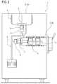
- FIG. 2is a schematic view of a machine of this invention for making liquid or semiliquid products
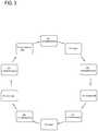
- FIG. 3schematically represents an algorithm implemented in the machine of the invention.
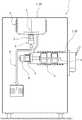
- the numeral 1denotes a machine for making liquid and semi-liquid products, comprising:
- the communication fieldbus 8is a serial bus and, still more preferably, a Modbus.
- the container 2is a cylindrical container.
- the container 2is axisymmetric.
- the container 2has a horizontal axis.
- the machinepreferably comprises a thermodynamic system whose operation is based on a heat carrier fluid and the heat exchanger 4 is configured to have the heat carrier fluid flowing through it.
- the exchanger 4forms part of the thermodynamic system.
- thermodynamic systemcomprises a compressor (not illustrated).
- the mixerhas one or more blades, or scraping elements (which extend radially from a central shaft).
- the mixer 3is configured to allow scraping the inside walls of the container 2 .
- the heat exchanger 4is provided with a flow circuit for heat carrier (heat exchange) fluid.
- FIG. 1shows a first embodiment of the machine 1 , where the container 2 is a processing (mixing and freezing) cylinder.
- FIG. 2shows a machine 1 provided with a tank 2 A for pre-treating the product (defining a first container 2 ) and a cylinder 2 B for processing the product (defining a second container 2 ).
- the machine of FIG. 2thus comprises a first motor and a first inverter for driving a first mixer operating in the first container 2 A and a second motor and a second inverter for driving a second mixer operating in the second container 2 B.
- the control unit 7is connected (by means of a single fieldbus or two fieldbuses 8 ) to the first and second inverters.
- control unit 7is connected to the first and second inverters by means of the same fieldbus 8 (in this case, each inverter has a unique identification ID used by the control unit to send transmission or request commands to the inverter).
- the machine 1is a machine for making ice cream (artisan and/or soft ice cream). More in general, the machine 1 can make any kind of liquid and/or semi-liquid product (for example, yogurt, chocolate, sorbets, creams and the like).
- control unit 7is programmed to run a first algorithm of the (finite) state machine type, for controlling the inverter.
- the machine 1(in particular, the control unit 7 ) comprises a hardware module (comprising one or more processors) and software instructions to be carried out by the hardware module and configured to run a first algorithm of the (finite) state machine type, for controlling the inverter.
- the state control algorithmcomprises at least the following states:
- the command transmitted to the inverteris one (or more) of the following: a start command for the motor unit, a stop command for the motor unit, a rotation frequency setting for the motor, an alarms zeroing.
- the motor start commandallows starting the motor, and hence the mixer 3 .
- the motor stop commandallows stopping the motor, and hence the mixer 3 .
- the rotation frequency setting commandallows setting the rotation frequency on the inverter 6 .
- the motoris actively managed and controlled by the inverter, without the control unit in any way controlling the motor drive parameters (for example, acceleration, deceleration) and the motor is thus controlled independently of the control unit, that is to say, solely by the operating logic implemented in the inverter.
- the rotation frequencyis a number belonging to a discrete set of values.
- the rotation frequencyis a value between 0, a first value, a second value and a third value.
- the alarm zeroing commandallows zeroing the alarms, if any, in the inverter registers.
- commandsconsist substantially of sending a request to write in one or more inverter registers.
- control unit 7can send one or more commands simultaneously.
- the first algorithmis run cyclically.
- the commands from the inverter cardare not sent according to a predetermined time scheme (for example at predetermined intervals) nor on the basis of events but are sent when the algorithm is in a specific state, in particular in the “transmission of command to the inverter” state.
- FIG. 3schematically illustrates how the commands and read requests are sent by the control unit 7 to the inverter 6 .
- commandslike the read requests, are sent according to a cyclic scheme, that is to say, cyclically.
- the first algorithmcyclically and alternately sends a command and a request to read an inverter operating parameter (as illustrated in FIG. 3 ).
- the command sent at each cycleis the same, whilst the requests to read an inverter operating parameter are different at each cycle (as shown in FIG. 3 , where the read requests are labelled RD, and the commands WR).
- the requests to read inverter operating parametersare sent by the control unit to the inverter when the algorithm is in the “transmission of a read request for an inverter operating parameter” state.
- the first algorithmthus defines a state machine which cyclically and iteratively sends commands and read requests to the inverter.
- the first algorithmis run substantially continuously from the moment the machine is started.
- the digital data sent through the bus 8relates only to commands for operation of the inverter and not to other signals from different sensors (temperature, pressure) which reach the control unit 7 through communication lines other than the communication bus 8 .
- control and operating unit 7is configured to run (preferably in parallel) a second algorithm of the state machine type, independent of the first algorithm, and configured to control one or more machine actuators, including the thermodynamic system (in particular the compressor of the thermodynamic system).
- the second algorithmis responsible for managing the progress of the process, while the first algorithm is substantially responsible for communication and control of the inverter 6 during processing.
- the second algorithmis configured to:
- the progress of the processis not controlled by the first algorithm but is controlled independently and separately by the second algorithm.
- Every recipe(for making a product) is made up of steps (phases). It should be noted that at each step, the second algorithm performs the aforementioned operations a) to c) until the last step is reached.
- the machine 1comprises a memory 71 —preferably ROM, or read-only memory—provided with a first data structure.
- the first data structureis an information set for different phases of each recipe.
- the algorithmpreferably reads the data structure at the start, and only at the start, of each phase of the process.
- the data retrieved, that is, read, from the data structureis memorized in global variables so as to be accessible both to the first and the second algorithm (which, to all intents and purposes, are independent).
- the first algorithmsets the initial command to be sent to the inverter 6 .
- the data in the data structureis not read again or compared with the data of the data structure.
- the second algorithmreads the data structure in order to retrieve from the data structure itself the information relating to commands to be performed during that phase and/or operating parameters of the machine 1 .
- the second algorithmis thus configured to read from the data structure—at the start of each phase—the information set for that phase, present in the data structure, in order to set the command to be transmitted to the inverter based on the information retrieved from the data structure.
- the data structurecomprises at least the following information for each recipe and phase:
- the machine 1comprises a first data structure, embodied by a ROM, which contains the programming values (factory set), and a second data structure, embodied by a second, different memory 72 which is non-volatile (writable) and which contains the user-settable values.
- a first data structureembodied by a ROM, which contains the programming values (factory set)
- a second data structureembodied by a second, different memory 72 which is non-volatile (writable) and which contains the user-settable values.
- the second data structurehas a structure identical to the first data structure.
- the algorithmretrieves information items both from the first and the second data structure.
- the functionis preferably one of the following:
- control unit 7activates a heater associated with the container 2 to heat the product inside the container 2 (the heater may be the selfsame heat exchanger 4 ).
- control unit 7activates a cooling element associated with the container 2 to cool the product inside the container 2 (the cooling element may be the selfsame heat exchanger 4 ).
- control unit 7commands the inverter 6 to activate the motor 5 .
- the heater and the cooling elementare defined by the exchanger 4 or by two different exchangers).
- the first algorithmis preferably configured to transmit—in the “transmission of a command to the inverter” state—a motor stop command, or a zero speed motor start command, associated with the “product storage” or “product ready” functions, corresponding to a condition of termination of preparation of the recipe.
- the machine 1comprises a user interface (not illustrated) provided with controls and configured to adjust one or more parameters of the command transmitted to the inverter.
- a user interface(not illustrated) provided with controls and configured to adjust one or more parameters of the command transmitted to the inverter.
- the interfaceallows modifying and saving to the data structure some of the values of the second data structure.
- the interfaceis provided with controls for adjusting the speed of rotation of the inverter, for allowing adjustment of the speed of rotation of the inverter.
- the usercan make a variegated product by adjusting the speed of rotation of the inverter as required.
- the machine 1is highly reliable in its operation and particularly easy to control.
- control unit 7reads the following operating parameters:
- alarm managementis performed within the first algorithm.
Landscapes
- Chemical & Material Sciences (AREA)
- Chemical Kinetics & Catalysis (AREA)
- Engineering & Computer Science (AREA)
- Food Science & Technology (AREA)
- Polymers & Plastics (AREA)
- Life Sciences & Earth Sciences (AREA)
- Manufacturing & Machinery (AREA)
- Physics & Mathematics (AREA)
- General Physics & Mathematics (AREA)
- Automation & Control Theory (AREA)
- Control Of Ac Motors In General (AREA)
- Confectionery (AREA)
- Control Of Electric Motors In General (AREA)
- Food-Manufacturing Devices (AREA)
- Control Of Multiple Motors (AREA)
Abstract
Description
- a
container 2 for processing the liquid and semi-liquid products; - a
mixer 3 operating inside theprocessing container 2; - a
heat exchanger 4, operatively associated with theprocessing container 2 for exchanging heat with the liquid or semi-liquid product inside thecontainer 2; - a
motor unit 5 operating on themixer 3 for driving it in rotation inside thecontainer 2; - an
inverter 6, connected to themotor unit 5 for controlling the operation of themotor unit 5; - a control and operating unit7 (hereinafter also called “control unit”), connected to the
inverter 6 for sending command signals S1 and receiving control signals S2, - a
communication fieldbus 8 interposed between theinverter 6 and the control unit7 for allowing the transmission of the command and control signals S1,S2 between theinverter 6 and the control unit7.
- a
- a) transmission of at least one command to the inverter;
- b) standby for confirmation that the inverter received the command;
- c) transmission of a read request for an inverter operating parameter;
- d) standby for receiving the inverter parameter.
- a) read the parameters of the step to be performed (from a first data structure and/or from a second data structure described below);
- b) command actuators as a function of the parameters read;
- c) increment the step counter.
- function (command) to be executed;
- ingredient to be displayed;
- desired inverter speed;
- inverter minimum command speed settable;
- inverter maximum command speed settable;
- phase execution time;
- minimum time settable;
- maximum time settable;
- desired product temperature;
- product minimum temperature settable;
- product maximum temperature settable;
- control temperature limits.
- heating;
- cooling;
- heating and stirring;
- cooling and stirring;
- stirring;
- product storage;
- product ready.
- the rotation torque of the motor;
- the state of logical inputs present at the inverter (these inputs may have external safety devices associated with them);
- the state of the alarms (alarm register and alarm code register).
Claims (8)
Applications Claiming Priority (3)
| Application Number | Priority Date | Filing Date | Title |
|---|---|---|---|
| ITBO20140670 | 2014-11-28 | ||
| ITBO2014A0670 | 2014-11-28 | ||
| ITBO2014A000670 | 2014-11-28 |
Publications (2)
| Publication Number | Publication Date |
|---|---|
| US20160150804A1 US20160150804A1 (en) | 2016-06-02 |
| US10617131B2true US10617131B2 (en) | 2020-04-14 |
Family
ID=52462990
Family Applications (1)
| Application Number | Title | Priority Date | Filing Date |
|---|---|---|---|
| US14/947,418ActiveUS10617131B2 (en) | 2014-11-28 | 2015-11-20 | Machine for making liquid or semi-liquid products equipped with fieldbus controlled inverter |
Country Status (5)
| Country | Link |
|---|---|
| US (1) | US10617131B2 (en) |
| EP (1) | EP3025589B1 (en) |
| JP (1) | JP6721970B2 (en) |
| CN (1) | CN105676684B (en) |
| SI (1) | SI3025589T1 (en) |
Cited By (10)
| Publication number | Priority date | Publication date | Assignee | Title |
|---|---|---|---|---|
| US11503959B2 (en) | 2020-12-31 | 2022-11-22 | Sharkninja Operating Llc | Micro puree machine |
| US11540669B2 (en) | 2020-12-31 | 2023-01-03 | Sharkninja Operating Llc | Micro puree machine |
| US11617378B2 (en) | 2020-12-31 | 2023-04-04 | Sharkninja Operating Llc | Micro puree machine |
| USD983603S1 (en) | 2020-12-31 | 2023-04-18 | Sharkninja Operating Llc | Blade for a micro puree machine |
| USD985331S1 (en) | 2020-12-31 | 2023-05-09 | Sharkninja Operating Llc | Housing for a micro puree machine |
| USD985334S1 (en) | 2020-12-31 | 2023-05-09 | Sharkninja Operating Llc | Nested bowl for a micro puree machine |
| US11672382B2 (en) | 2020-12-31 | 2023-06-13 | Sharkninja Operating Llc | Micro puree machine |
| US11864690B2 (en) | 2020-12-31 | 2024-01-09 | Sharkninja Operating Llc | Micro puree machine |
| US12016496B2 (en) | 2020-12-31 | 2024-06-25 | Sharkninja Operating Llc | Micro puree machine |
| US12022979B2 (en) | 2020-12-31 | 2024-07-02 | Sharkninja Operating Llc | Micro puree machine |
Families Citing this family (2)
| Publication number | Priority date | Publication date | Assignee | Title |
|---|---|---|---|---|
| IT201900002111A1 (en) | 2019-02-13 | 2020-08-13 | Ali Group Srl Carpigiani | MACHINE FOR THE PRODUCTION OF LIQUID OR SEMIQUID FOOD PRODUCTS. |
| CN112691596B (en)* | 2020-11-24 | 2022-07-01 | 内蒙古蒙牛乳业(集团)股份有限公司 | Uniform mixing device and ice product manufacturing equipment |
Citations (19)
| Publication number | Priority date | Publication date | Assignee | Title |
|---|---|---|---|---|
| US4703628A (en)* | 1984-08-10 | 1987-11-03 | Sanyo Electric Co. | Apparatus for preparing frozen products |
| FR2731877A1 (en) | 1995-03-24 | 1996-09-27 | Bravo Spa | Food mixer for creams and pastes |
| US5829224A (en)* | 1997-10-10 | 1998-11-03 | Tetra Laval Holdings & Finance, Sa | Method and apparatus for producing an aseptic heterogeneous food |
| US6001404A (en)* | 1996-07-26 | 1999-12-14 | Meiji Seika Kaisha Ltd. | Method of making coated ball-shaped frozen dessert product |
| JP2002176924A (en) | 2000-12-13 | 2002-06-25 | Mitsubishi Heavy Ind Ltd | Apparatus for frozen dessert food production and method for hardness control thereof |
| US20050029174A1 (en)* | 2003-08-08 | 2005-02-10 | Collins Carol Ann | Hybrid magnetohydrodynamo (MHD) field sanitation generator for treating wastewater, sewages & sludge and recovering potable water |
| US20050081554A1 (en)* | 2003-10-15 | 2005-04-21 | Harold F. Ross | Ice cream machine with specialized motor |
| US20060283196A1 (en)* | 2005-06-16 | 2006-12-21 | Uwe Rosenbaum | Process and apparatus for continuous cooling of pumpable material with a liquid cryogen |
| EP2082649A2 (en) | 2008-01-25 | 2009-07-29 | ALI S.p.A. - CARPIGIANI GROUP | Machine and method for the treatment of liquid or semi-liquid food mixtures. |
| US20090193828A1 (en)* | 2008-01-31 | 2009-08-06 | Gino Cocchi | Machine for producing and dispensing liquid and semi-liquid consumer food products |
| CN101607531A (en) | 2008-06-19 | 2009-12-23 | 通用汽车环球科技运作公司 | The double-ended inverter drive system and the method for operation that are used for fuel cell vehicle |
| US20110108569A1 (en)* | 2006-01-31 | 2011-05-12 | Jones Allan S | Method and apparatus for dispensing frozen confectionery |
| WO2011057692A1 (en) | 2009-11-10 | 2011-05-19 | G.S.G. S.R.L. | Improved process for the processing of food products, in particular for the processing of ice-cream, and machine for effecting said process |
| CN102299535A (en) | 2010-06-25 | 2011-12-28 | 法雷奥电机控制系统公司 | Device for charging accumulator means |
| JP2012257153A (en) | 2011-06-10 | 2012-12-27 | Toshiba Schneider Inverter Corp | Inverter device |
| US20130129885A1 (en)* | 2010-05-31 | 2013-05-23 | Tuttoespresso S.R.L. | Device and method for preparation of beverages with differing tastes |
| US20130147431A1 (en) | 2011-12-09 | 2013-06-13 | Research & Business Foundation Sungkyunkwan University | Recharge systems and methods |
| US8479352B2 (en) | 2008-04-30 | 2013-07-09 | Carlos Rivadulla Oliva | Mop bucket with two compartments |
| EP2783574A1 (en) | 2013-03-28 | 2014-10-01 | ALI S.p.A. - CARPIGIANI GROUP | Method and apparatus for making and dispensing liquid or semi-liquid food products. |
Family Cites Families (2)
| Publication number | Priority date | Publication date | Assignee | Title |
|---|---|---|---|---|
| US7845508B2 (en)* | 2005-01-28 | 2010-12-07 | Rothschild Wayne H | Multipurpose storage device and method |
| US20120021536A1 (en)* | 2010-07-23 | 2012-01-26 | Primestar Solar, Inc. | Method and system for application of an insulating dielectric material to photovoltaic module substrates |
- 2015
- 2015-11-10SISI201530937Tpatent/SI3025589T1/enunknown
- 2015-11-10EPEP15193773.7Apatent/EP3025589B1/enactiveActive
- 2015-11-20USUS14/947,418patent/US10617131B2/enactiveActive
- 2015-11-24CNCN201511035791.2Apatent/CN105676684B/enactiveActive
- 2015-11-27JPJP2015231472Apatent/JP6721970B2/enactiveActive
Patent Citations (23)
| Publication number | Priority date | Publication date | Assignee | Title |
|---|---|---|---|---|
| US4703628A (en)* | 1984-08-10 | 1987-11-03 | Sanyo Electric Co. | Apparatus for preparing frozen products |
| FR2731877A1 (en) | 1995-03-24 | 1996-09-27 | Bravo Spa | Food mixer for creams and pastes |
| US6001404A (en)* | 1996-07-26 | 1999-12-14 | Meiji Seika Kaisha Ltd. | Method of making coated ball-shaped frozen dessert product |
| US5829224A (en)* | 1997-10-10 | 1998-11-03 | Tetra Laval Holdings & Finance, Sa | Method and apparatus for producing an aseptic heterogeneous food |
| JP2002176924A (en) | 2000-12-13 | 2002-06-25 | Mitsubishi Heavy Ind Ltd | Apparatus for frozen dessert food production and method for hardness control thereof |
| US20050029174A1 (en)* | 2003-08-08 | 2005-02-10 | Collins Carol Ann | Hybrid magnetohydrodynamo (MHD) field sanitation generator for treating wastewater, sewages & sludge and recovering potable water |
| US20050081554A1 (en)* | 2003-10-15 | 2005-04-21 | Harold F. Ross | Ice cream machine with specialized motor |
| US20060283196A1 (en)* | 2005-06-16 | 2006-12-21 | Uwe Rosenbaum | Process and apparatus for continuous cooling of pumpable material with a liquid cryogen |
| US20110108569A1 (en)* | 2006-01-31 | 2011-05-12 | Jones Allan S | Method and apparatus for dispensing frozen confectionery |
| EP2082649A2 (en) | 2008-01-25 | 2009-07-29 | ALI S.p.A. - CARPIGIANI GROUP | Machine and method for the treatment of liquid or semi-liquid food mixtures. |
| US8479532B2 (en)* | 2008-01-25 | 2013-07-09 | Carpigiani Group-Ali S.P.A. | Machine and method for the treatment of liquid or semi-liquid food mixtures |
| US20090193828A1 (en)* | 2008-01-31 | 2009-08-06 | Gino Cocchi | Machine for producing and dispensing liquid and semi-liquid consumer food products |
| US8479352B2 (en) | 2008-04-30 | 2013-07-09 | Carlos Rivadulla Oliva | Mop bucket with two compartments |
| CN101607531A (en) | 2008-06-19 | 2009-12-23 | 通用汽车环球科技运作公司 | The double-ended inverter drive system and the method for operation that are used for fuel cell vehicle |
| US20120215361A1 (en) | 2009-11-10 | 2012-08-23 | G.S.G. S.R.L. | process for the processing of food products, in particular for the processing of ice-cream, and machine for effecting said process |
| WO2011057692A1 (en) | 2009-11-10 | 2011-05-19 | G.S.G. S.R.L. | Improved process for the processing of food products, in particular for the processing of ice-cream, and machine for effecting said process |
| US20130129885A1 (en)* | 2010-05-31 | 2013-05-23 | Tuttoespresso S.R.L. | Device and method for preparation of beverages with differing tastes |
| US20120049770A1 (en) | 2010-06-25 | 2012-03-01 | Valeo Systemes De Controle Moteur | Device for charging accumulator means |
| CN102299535A (en) | 2010-06-25 | 2011-12-28 | 法雷奥电机控制系统公司 | Device for charging accumulator means |
| JP2012257153A (en) | 2011-06-10 | 2012-12-27 | Toshiba Schneider Inverter Corp | Inverter device |
| US20130147431A1 (en) | 2011-12-09 | 2013-06-13 | Research & Business Foundation Sungkyunkwan University | Recharge systems and methods |
| CN103166278A (en) | 2011-12-09 | 2013-06-19 | 现代自动车株式会社 | Recharge systems and methods |
| EP2783574A1 (en) | 2013-03-28 | 2014-10-01 | ALI S.p.A. - CARPIGIANI GROUP | Method and apparatus for making and dispensing liquid or semi-liquid food products. |
Non-Patent Citations (4)
| Title |
|---|
| Chinese Office Action dated Jan. 8, 2019 for counterpart Chinese Application No. 201511035791.2. |
| European Search Report dated Apr. 28, 2016 from counterpart European App No. 15193773.7. |
| Italian Search Report dated Aug. 13, 2015 from related Italian Patent Application No. IT BO20140670. |
| Japanese Office Action dated Jan. 7, 2020 for counterpart Japanese Application No. 2015231472. |
Cited By (18)
| Publication number | Priority date | Publication date | Assignee | Title |
|---|---|---|---|---|
| US11503959B2 (en) | 2020-12-31 | 2022-11-22 | Sharkninja Operating Llc | Micro puree machine |
| US11540669B2 (en) | 2020-12-31 | 2023-01-03 | Sharkninja Operating Llc | Micro puree machine |
| US11617378B2 (en) | 2020-12-31 | 2023-04-04 | Sharkninja Operating Llc | Micro puree machine |
| USD983603S1 (en) | 2020-12-31 | 2023-04-18 | Sharkninja Operating Llc | Blade for a micro puree machine |
| USD985331S1 (en) | 2020-12-31 | 2023-05-09 | Sharkninja Operating Llc | Housing for a micro puree machine |
| USD985334S1 (en) | 2020-12-31 | 2023-05-09 | Sharkninja Operating Llc | Nested bowl for a micro puree machine |
| US11641978B2 (en) | 2020-12-31 | 2023-05-09 | Sharkninja Operating Llc | Micro puree machine |
| US11672382B2 (en) | 2020-12-31 | 2023-06-13 | Sharkninja Operating Llc | Micro puree machine |
| US11832767B2 (en) | 2020-12-31 | 2023-12-05 | Sharkninja Operating Llc | Micro puree machine |
| USD1008735S1 (en) | 2020-12-31 | 2023-12-26 | Sharkninja Operating Llc | Blade for a micro puree machine |
| US11864690B2 (en) | 2020-12-31 | 2024-01-09 | Sharkninja Operating Llc | Micro puree machine |
| US11871765B2 (en) | 2020-12-31 | 2024-01-16 | Sharkninja Operating Llc | Micro puree machine |
| US11925298B2 (en) | 2020-12-31 | 2024-03-12 | Sharkninja Operating Llc | Micro puree machine |
| US12016496B2 (en) | 2020-12-31 | 2024-06-25 | Sharkninja Operating Llc | Micro puree machine |
| US12016493B2 (en) | 2020-12-31 | 2024-06-25 | Sharkninja Operating Llc | Micro puree machine |
| US12022979B2 (en) | 2020-12-31 | 2024-07-02 | Sharkninja Operating Llc | Micro puree machine |
| US12064056B2 (en) | 2020-12-31 | 2024-08-20 | Sharkninja (Hong Kong) Company Limited | Micro puree machine |
| USD1041252S1 (en) | 2020-12-31 | 2024-09-10 | Sharkninja Operating Llc | Bowl for a micro puree machine |
Also Published As
| Publication number | Publication date |
|---|---|
| US20160150804A1 (en) | 2016-06-02 |
| EP3025589A1 (en) | 2016-06-01 |
| SI3025589T1 (en) | 2020-02-28 |
| CN105676684A (en) | 2016-06-15 |
| CN105676684B (en) | 2019-08-13 |
| JP2016123260A (en) | 2016-07-07 |
| EP3025589B1 (en) | 2019-07-24 |
| JP6721970B2 (en) | 2020-07-15 |
Similar Documents
| Publication | Publication Date | Title |
|---|---|---|
| US10617131B2 (en) | Machine for making liquid or semi-liquid products equipped with fieldbus controlled inverter | |
| US11540533B2 (en) | Method and apparatus for making and dispensing liquid or semi-liquid food products | |
| JP7085354B2 (en) | Machines for producing liquid or semi-liquid foods | |
| JP2016123260A5 (en) | ||
| EP3442351B1 (en) | Viscous semi-liquid food dispenser and method and system for controlling food characteristics | |
| KR102538604B1 (en) | Machine for making liquid or semi-liquid products | |
| CN104782875B (en) | Machine and method for making and dispensing ice cream | |
| US10123553B2 (en) | Machine and method for making liquid or semi-liquid products | |
| EP2599391B1 (en) | Machine and method for the treatment of liquid or semi-liquid food mixtures | |
| EP2805619B1 (en) | Machine and method for making chocolate | |
| CN101842022A (en) | Machine for producing and dispensing liquid or semiliquid food products | |
| US20210179409A1 (en) | System and method for filling a container with a fluid and/or operating a mixing system | |
| JP6874511B2 (en) | Output control unit, output control system, control method of output control unit | |
| JP7465233B2 (en) | Manufacturing Systems and Programs | |
| KR102062211B1 (en) | System for manufacturing Gochujang | |
| EP2615512A1 (en) | Apparatus for the centralized management of machines for the production of food products | |
| EP3173708B1 (en) | Air-conditioning system | |
| JPH0474602A (en) | Heating device and heating method for slurry | |
| ITBO20130127U1 (en) | MACHINE FOR THE TREATMENT OF LIQUID OR SEMILEQUID FOOD MIXTURES. | |
| CN107490988A (en) | A kind of compressor intelligent variable frequency control system | |
| TWM469314U (en) | Servo synchronization control system |
Legal Events
| Date | Code | Title | Description |
|---|---|---|---|
| AS | Assignment | Owner name:ALI S.P.A. - CARPIGIANI GROUP, ITALY Free format text:ASSIGNMENT OF ASSIGNORS INTEREST;ASSIGNORS:LAZZARINI, ROBERTO;COCCHI, ANDREA;REEL/FRAME:037102/0614 Effective date:20151111 | |
| STPP | Information on status: patent application and granting procedure in general | Free format text:FINAL REJECTION MAILED | |
| AS | Assignment | Owner name:ALI GROUP S.R.L. - CARPIGIANI, ITALY Free format text:ASSIGNMENT OF ASSIGNORS INTEREST;ASSIGNOR:ALI S.P.A. - CARPIGIANI GROUP;REEL/FRAME:048288/0459 Effective date:20180219 | |
| STPP | Information on status: patent application and granting procedure in general | Free format text:RESPONSE AFTER FINAL ACTION FORWARDED TO EXAMINER | |
| STPP | Information on status: patent application and granting procedure in general | Free format text:NON FINAL ACTION MAILED | |
| STPP | Information on status: patent application and granting procedure in general | Free format text:RESPONSE TO NON-FINAL OFFICE ACTION ENTERED AND FORWARDED TO EXAMINER | |
| STPP | Information on status: patent application and granting procedure in general | Free format text:NOTICE OF ALLOWANCE MAILED -- APPLICATION RECEIVED IN OFFICE OF PUBLICATIONS | |
| STPP | Information on status: patent application and granting procedure in general | Free format text:AWAITING TC RESP., ISSUE FEE NOT PAID | |
| STPP | Information on status: patent application and granting procedure in general | Free format text:PUBLICATIONS -- ISSUE FEE PAYMENT RECEIVED | |
| STCF | Information on status: patent grant | Free format text:PATENTED CASE | |
| MAFP | Maintenance fee payment | Free format text:PAYMENT OF MAINTENANCE FEE, 4TH YEAR, LARGE ENTITY (ORIGINAL EVENT CODE: M1551); ENTITY STATUS OF PATENT OWNER: LARGE ENTITY Year of fee payment:4 |