US10616954B2 - Electrical barrier for wax warmer - Google Patents
Electrical barrier for wax warmerDownload PDFInfo
- Publication number
- US10616954B2 US10616954B2US15/784,427US201715784427AUS10616954B2US 10616954 B2US10616954 B2US 10616954B2US 201715784427 AUS201715784427 AUS 201715784427AUS 10616954 B2US10616954 B2US 10616954B2
- Authority
- US
- United States
- Prior art keywords
- electrical
- base plate
- wax warmer
- sleeve
- heater
- Prior art date
- Legal status (The legal status is an assumption and is not a legal conclusion. Google has not performed a legal analysis and makes no representation as to the accuracy of the status listed.)
- Active
Links
Images


Classifications
- H—ELECTRICITY
- H05—ELECTRIC TECHNIQUES NOT OTHERWISE PROVIDED FOR
- H05B—ELECTRIC HEATING; ELECTRIC LIGHT SOURCES NOT OTHERWISE PROVIDED FOR; CIRCUIT ARRANGEMENTS FOR ELECTRIC LIGHT SOURCES, IN GENERAL
- H05B1/00—Details of electric heating devices
- H05B1/02—Automatic switching arrangements specially adapted to apparatus ; Control of heating devices
- H05B1/0227—Applications
- H05B1/0252—Domestic applications
- A—HUMAN NECESSITIES
- A61—MEDICAL OR VETERINARY SCIENCE; HYGIENE
- A61L—METHODS OR APPARATUS FOR STERILISING MATERIALS OR OBJECTS IN GENERAL; DISINFECTION, STERILISATION OR DEODORISATION OF AIR; CHEMICAL ASPECTS OF BANDAGES, DRESSINGS, ABSORBENT PADS OR SURGICAL ARTICLES; MATERIALS FOR BANDAGES, DRESSINGS, ABSORBENT PADS OR SURGICAL ARTICLES
- A61L9/00—Disinfection, sterilisation or deodorisation of air
- A61L9/015—Disinfection, sterilisation or deodorisation of air using gaseous or vaporous substances, e.g. ozone
- A61L9/02—Disinfection, sterilisation or deodorisation of air using gaseous or vaporous substances, e.g. ozone using substances evaporated in the air by heating or combustion
- A61L9/03—Apparatus therefor
- H—ELECTRICITY
- H05—ELECTRIC TECHNIQUES NOT OTHERWISE PROVIDED FOR
- H05B—ELECTRIC HEATING; ELECTRIC LIGHT SOURCES NOT OTHERWISE PROVIDED FOR; CIRCUIT ARRANGEMENTS FOR ELECTRIC LIGHT SOURCES, IN GENERAL
- H05B3/00—Ohmic-resistance heating
- H05B3/0033—Heating devices using lamps
- H05B3/0038—Heating devices using lamps for industrial applications
- H05B3/0052—Heating devices using lamps for industrial applications for fluid treatments
- H—ELECTRICITY
- H05—ELECTRIC TECHNIQUES NOT OTHERWISE PROVIDED FOR
- H05B—ELECTRIC HEATING; ELECTRIC LIGHT SOURCES NOT OTHERWISE PROVIDED FOR; CIRCUIT ARRANGEMENTS FOR ELECTRIC LIGHT SOURCES, IN GENERAL
- H05B3/00—Ohmic-resistance heating
- H05B3/20—Heating elements having extended surface area substantially in a two-dimensional plane, e.g. plate-heater
- H05B3/22—Heating elements having extended surface area substantially in a two-dimensional plane, e.g. plate-heater non-flexible
- H05B3/26—Heating elements having extended surface area substantially in a two-dimensional plane, e.g. plate-heater non-flexible heating conductor mounted on insulating base
- A—HUMAN NECESSITIES
- A61—MEDICAL OR VETERINARY SCIENCE; HYGIENE
- A61L—METHODS OR APPARATUS FOR STERILISING MATERIALS OR OBJECTS IN GENERAL; DISINFECTION, STERILISATION OR DEODORISATION OF AIR; CHEMICAL ASPECTS OF BANDAGES, DRESSINGS, ABSORBENT PADS OR SURGICAL ARTICLES; MATERIALS FOR BANDAGES, DRESSINGS, ABSORBENT PADS OR SURGICAL ARTICLES
- A61L2209/00—Aspects relating to disinfection, sterilisation or deodorisation of air
- A61L2209/10—Apparatus features
- A61L2209/13—Dispensing or storing means for active compounds
- A61L2209/135—Vaporisers for active components
- H—ELECTRICITY
- H05—ELECTRIC TECHNIQUES NOT OTHERWISE PROVIDED FOR
- H05B—ELECTRIC HEATING; ELECTRIC LIGHT SOURCES NOT OTHERWISE PROVIDED FOR; CIRCUIT ARRANGEMENTS FOR ELECTRIC LIGHT SOURCES, IN GENERAL
- H05B2203/00—Aspects relating to Ohmic resistive heating covered by group H05B3/00
- H05B2203/02—Heaters using heating elements having a positive temperature coefficient
- H—ELECTRICITY
- H05—ELECTRIC TECHNIQUES NOT OTHERWISE PROVIDED FOR
- H05B—ELECTRIC HEATING; ELECTRIC LIGHT SOURCES NOT OTHERWISE PROVIDED FOR; CIRCUIT ARRANGEMENTS FOR ELECTRIC LIGHT SOURCES, IN GENERAL
- H05B2203/00—Aspects relating to Ohmic resistive heating covered by group H05B3/00
- H05B2203/021—Heaters specially adapted for heating liquids
- H—ELECTRICITY
- H05—ELECTRIC TECHNIQUES NOT OTHERWISE PROVIDED FOR
- H05B—ELECTRIC HEATING; ELECTRIC LIGHT SOURCES NOT OTHERWISE PROVIDED FOR; CIRCUIT ARRANGEMENTS FOR ELECTRIC LIGHT SOURCES, IN GENERAL
- H05B2203/00—Aspects relating to Ohmic resistive heating covered by group H05B3/00
- H05B2203/022—Heaters specially adapted for heating gaseous material
Definitions
- the present disclosuregenerally relates to an electrical barrier for a wax warmer, and more specifically, to an electrical barrier that inhibits a user from contacting live electrical components when a body of the wax warmer is broken or damaged.
- Candleshave been used for centuries to provide illumination and pleasant aromas to the surrounding environment.
- a candleconsists of a wick dipped in wax.
- the wickis lit and provides light while the burning or melting wax may provide a pleasant aroma.
- unscented or scented candles or wax meltscan be placed in a warmer.
- These candles or warmersmay also be used to provide more than just illumination and/or pleasant fragrances.
- candles and warmersmay be placed outside around a patio or deck.
- the wax or oilmay include materials with insect repellant properties along with providing a pleasant aroma and/or illumination.
- userscan burn or warm waxes and oils to provide desired effects to the surrounding atmosphere or environment.
- candlesmay be forgotten and left unsupervised and may represent a fire hazard. Also, a candle flame may be extinguished with a slight breeze or gust of wind.
- An additional drawback associated with candlesis the inability to control the intensity of the heat being provided to the scented material. A candle flame is not easily adjustable and thus the amount of heat the flame provides to the infused wax or oil does not allow a user to vary the strength of the fragrance introduced into the surrounding environment.
- An electric wax warmerconsists of a heater in thermal contact with a reservoir for holding a wax melt or infused oil.
- the heaterreplaces the candle in a traditional warmer and melts the wax or heats the oil in the reservoir, resulting in the same benefits as previously mentioned.
- the lack of a flamereduces the risks associated with traditional warmers and candles.
- Another advantagemay be the temperature of the heater in an electric wax warmer can be adjusted. This provides the user with more control over the amount of fragrant or other materials introduced into the surrounding environment. Electric wax warmers also have more consistent performance indoors and outdoors and are less messy than traditional candles and warmers.
- Electric wax warmersmay have significant advantages over traditional warmers and candles, however, they may also have some drawbacks.
- Many of the traditional electric wax warmersinclude a housing, commonly constructed of a ceramic material, which encloses the various electrical components necessary for heating the wax melt or infused oil. Thus, if the ceramic housing is broken, the various electrical components may be exposed, allowing a user to come into contact with live electrical components.
- the UL 283 standard for air fresheners and deodorizersrequires ceramic wax warmers to undergo an impact performance test using a 535 gram, 5.08 centimeter diameter smooth, solid steel ball that is dropped from a specified height of 60 centimeters. Once the steel ball is dropped onto the ceramic housing, a finger probe may be used, assuming the ceramic housing is damaged, in an attempt to contact the electrical components of the wax warmer. According to the UL 283 standard, if the finger probe can contact the electrical components through the broken ceramic housing, the wax warmer does not pass the ball impact test.
- the present disclosureovercomes some of the aforementioned drawbacks by providing an electrical barrier for a wax warmer that is in compliance with the UL 283 standard.
- the present disclosuresatisfies the existing need for a wax warmer that includes an electrical barrier to inhibit a user from contacting live electrical components.
- the present disclosuresatisfies the need for an electrical barrier for a wax warmer that is easy to manufacture, thus keeping manufacturing costs and material usage down.
- a wax warmerincludes a body, an electrical assembly, a base plate, and a sleeve.
- the electrical assemblyis positioned within an interior space of the body and includes an electrical cord that extends outside the body.
- the sleeveforms an electrical barrier positioned within the interior space and surrounding the electrical assembly.
- the sleeveis coupled to the base plate and a portion of the electrical cord that passes through an opening in the sleeve is retained by the base plate and the sleeve.
- a wax warmerincludes a body, an electrical assembly, an electrical cord, and an annular sleeve.
- the electrical assemblyis positioned within an interior space of the body.
- the electrical cordcouples to the electrical assembly.
- the annular sleeveis positioned within the interior space of the body. The annular sleeve surrounds the entire electrical assembly and retains a portion of the electrical cord within the body.
- a wax warmerincludes a body, a reservoir, an electrical assembly, and an annular sleeve.
- the bodyincludes a top plate and a base plate.
- the reservoiris positioned on the top plate of the body.
- the electrical assemblyis positioned within an interior space of the body.
- the annular sleeveis coupled to the base plate and forms an electrical barrier.
- the annular sleeveis also positioned within the interior space and surrounds the electrical assembly within the body.
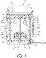
- FIG. 1is a cross-sectional side elevational view of a wax warmer
- FIG. 2is a schematic view of a wax warmer with an electrical barrier
- FIG. 3Ais a side elevational view of an electrical barrier layout according to one embodiment of the disclosure.
- FIG. 3Bis a perspective view of the electrical barrier of FIG. 3A coupled together to form a generally cylindrical shape
- FIG. 4is a cross-sectional view of the wax warmer taken generally along the line 4 - 4 of FIG. 2 with the electrical barrier in a first position;
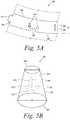
- FIG. 5Ais a side elevational view of an electrical barrier layout according to another embodiment of the disclosure.
- FIG. 5Bis a perspective view of the electrical barrier of FIG. 5A coupled together to form a generally frusto-conical shape
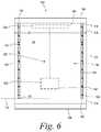
- FIG. 6is a cross-sectional view of the wax warmer taken generally along the line 6 - 6 of FIG. 2 with the electrical barrier in a second position;
- FIG. 7is a cross-sectional view of the wax warmer taken generally along the line 7 - 7 of FIG. 2 with the electrical barrier in a third position;
- FIG. 8is an image of a wax warmer undergoing a ball impact test
- FIG. 9is an image of the wax warmer of FIG. 8 after the ball impact test showing an electrical barrier
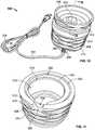
- FIG. 10is perspective view of another embodiment of a wax warmer
- FIG. 11is perspective view of a bottom end of a body of the wax warmer of FIG. 10 ;
- FIG. 12is a perspective view of a top end of the body of the wax warmer of FIG. 10 ;
- FIG. 13is a perspective view of the bottom end of the assembled wax warmer of FIG. 10 ;
- FIG. 14is a perspective view of the top end of the wax warmer of FIG. 10 with the reservoir removed exposing a heater plate;
- FIG. 15is a perspective view of a base plate of the wax warmer of FIG. 10 ;
- FIG. 16is a perspective view of the base plate of FIG. 15 assembled with a portion of an electrical cord
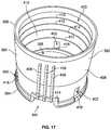
- FIG. 17is a front perspective view of a sleeve that forms an electrical barrier of the wax warmer of FIG. 10 ;
- FIG. 18is a rear perspective view of the sleeve of FIG. 17 ;
- FIG. 19is a perspective view of the sleeve of FIG. 17 assembled with the base plate and electrical cord of FIG. 16 and the heater plate of FIG. 14 ;
- FIG. 20is a cross section of the wax warmer of FIG. 10 taken along the line 20 - 20 shown in FIG. 10 ;
- FIG. 21is a perspective view of the body of the wax warmer of FIG. 10 assembled with the base plate and the sleeve;
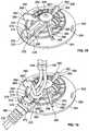
- FIG. 22is a perspective view of the bottom of the heater plate of the wax warmer of FIG. 10 ;
- FIG. 23is another perspective view of the heater plate of FIG. 22 ;
- FIG. 24is a side elevational view of the heater plate of FIG. 22 depicting the heater assembly installed and retained in contact with the heater plate.
- the wax warmer 100is designed to heat a wax melt 102 and thereby release a fragrance or other material contained therein into the surrounding environment.
- the wax warmer 100generally includes a body 104 , a reservoir 106 , and a heater assembly 108 .
- the body 104is fashioned to house the heater assembly 108 and provide a support structure for the reservoir 106 .
- the wax warmer 100is generally described to include the aforementioned components, but the wax warmer 100 may be adapted to add or remove various components according to specific user requirements.
- the body 104includes a sidewall 110 having a bottom end 112 and a top end 114 .
- the sidewall 110is generally cylindrical in shape and defines an interior space 116 .
- the bottom end 112defines a first opening 118 .
- a lip 120extends from an inner surface 122 of the sidewall 110 .
- the bottom end 112 and the lip 120form a recess 124 adapted to receive a base plate 126 that is disposed adjacent the bottom end 112 of the body 104 .
- Portions of the bottom end 112 of the body 104may include extensions (not shown) or other structures (feet, pads, structures with high coefficients of friction, etc.) generally known to those having ordinary skill in the art to provide stability to the wax warmer 100 .
- the sidewall 110further includes one or more apertures 128 provided therein.
- the apertures 128may be adapted to receive a light emissive or transmissive cover (not shown) and/or an indicator, such as an LED, or sensor (not shown).
- the apertures 128may allow light, provided by an electrical light source 130 , from the interior space 116 to be visible through the apertures 128 .
- one or more of the apertures 128may be fully or partially unobstructed to facilitate cooling of the body 104 and/or the flow of air through the interior space 116 of the wax warmer 100 .
- the apertures 128may be any desired shape and size for aesthetics, cooling, and light passage.
- the apertures 128may be circular (as shown in FIG.
- a second aperture 134is also provided proximal to the bottom end 112 of the sidewall 110 .
- the second aperture 134provides a pass-through for an electrical cord 132 in electrical communication with the electrical light source 130 and the heater assembly 108 .
- a second opening 140is provided at the top end 114 of the sidewall 110 .
- the second opening 140is bounded by a shoulder 142 extending radially inwardly from the inner surface 122 of the sidewall 110 .
- the second opening 140 and the shoulder 142are adapted to receive the heater assembly 108 and the reservoir 106 .
- the body 104 and the reservoir 106are preferably made from a ceramic material.
- any other materials as known to those having ordinary skill in the artmay be used, such as plastic, metal, stone or other natural materials, etc.
- the body 104 and the reservoir 106may take any geometric shape, e.g. a square, to provide different appearances.
- the exterior surfaces of the body 104 and the reservoir 106may be provided with any type of surface indicia, raised patterns, or any other decorations to configure the wax warmer 100 for aesthetic purposes.
- an electrical assembly 152 of the wax warmer 100 described abovemay be at least partially disposed within the interior space 116 of the body 104 .
- the electrical assembly 152may include the heater assembly 108 and the electrical light source 130 .
- structural componentsmay hold some of the various components in place.
- a threaded rod 166may extend through the base plate 126 and the electrical light source 130 and may abut against the heater assembly 108 .
- At least one nut 154may hold the threaded rod 166 and the various components in place.
- the heater assembly 108may be positioned within the body 104 proximate the second opening 140 such that the heater assembly 108 may heat the wax melt 102 in the reservoir 106 .
- the electrical light source 130may be positioned within the body 104 at a location distant to that of the heater assembly 108 , such as proximate the first opening 118 of the bottom end 112 . In other embodiments, the electrical light source 130 may be positioned within the body 104 at a location proximate the heater assembly 108 .
- the heater assembly 108may be a heat source such as a resistance heater, an incandescent light bulb, a PTC heater, or any other heater known to one in the art.
- the wax warmer 100includes a top plate 150 under the reservoir 106 .
- the top plate 150may be formed from a metallic material and disposed adjacent the top end 114 of the body 104 .
- the heater assembly 108may be abutted against or otherwise thermally coupled to a surface of the top plate 150 .
- the heater assembly 108may be coupled to the top plate 150 with an adhesive, with a mechanical connection (e.g., a clip, screw, interference fit, etc.), by being pushed against the top plate 150 with the threaded rod 166 (as shown), or any combination thereof.
- the top plate 150may be attached to one of the reservoir 106 or the body 104 or neither. In some embodiments, the wax warmer 100 may not include the top plate 150 . In such embodiments, the heater assembly 108 may abut directly against a bottom of the reservoir 106 .
- FIG. 2a simplified schematic diagram of the wax warmer 100 is shown.
- the wax warmer 100includes substantially the same components as described with reference to FIG. 1 , therefore similar reference numerals will be used.
- An electrical barrier 156is positioned inside the body 104 of the wax warmer 100 in the embodiment shown in FIG. 2 (see also FIG. 1 ).
- the electrical barrier 156may take the form of an annular sleeve, for example, and surround the electrical assembly 152 .
- the electrical assembly 152including the heater assembly 108 and electrical light source 130 , are not exposed to a user of the wax warmer 100 .
- the electrical barrier 156ensures that the wax warmer 100 is in compliance with standards related to air fresheners and deodorizers, such as the UL 283 standard, as will be described in further detail below.
- FIGS. 3A and 3BA first embodiment of the electrical barrier 156 is shown in FIGS. 3A and 3B .
- the electrical barrier 156can begin as a flat, substantially rectangular layout, as shown in FIG. 3A having a length dimension L and a height dimension H.
- the length dimension L and the height dimension Hmay vary depending on the dimensions of the particular wax warmer 100 the electrical barrier 156 is used in. In a preferred embodiment, the length dimension L is about 22.5 centimeters, and the height dimension H is about 5.7 centimeters.
- the electrical barrier 156may have a thickness dimension T (see FIG. 4 ) that is preferably between about 0.025 centimeters and about 0.15 centimeters.
- the length dimension Lmay be any suitable length to allow the electrical barrier 156 to fit within the body 104 of the wax warmer 100 .
- the height dimension Hmay be of any height to allow the electrical barrier 156 to fit within the body 104 and not extend beyond the base plate 126 or the top plate 150 of the wax warmer 100 .
- the thickness dimension Tmay vary depending on the specific wax warmer 100 that the electrical barrier 156 is used in. For example, depending on the heater assembly 108 used in a particular wax warmer 100 , the thickness dimension T may change in order to withstand a variety of heat outputs.
- the electrical barrier 156includes a top edge 158 and a bottom edge 160 that extend the length dimension L.
- the top edge 158is parallel to the bottom edge 160 .
- a first side edge 162 and a second side edge 164extend about the height dimension H.
- the first and second side edges 162 , 164are substantially parallel to one another.
- a groove 168is provided adjacent to the first side edge 162
- a tongue portion 170is provided adjacent to the second side edge 164 .
- the groove 168is configured to receive the tongue portion 170 to form a substantially cylindrical electrical barrier 156 .
- first side edge 162 and the second side edge 164may be heat sealed, adhered, or coupled together using any suitable mechanical fastener (e.g., a staple or a rivet).
- first side edge 162 and the second side edge 164may be integrally molded together to form the electrical barrier 156 .
- the electrical barrier 156may take the form of a sleeve that has a substantially circular cross-section when taken through a horizontal axis (axis-x in FIG. 4 ).
- the horizontal cross-section of the electrical barrier 156is oval, circular, curvilinear, triangular, or any suitable shape in order to shield the electrical assembly 152 .
- the electrical barrier 156is a right circular cylinder.
- the electrical barrier 156can also take the form of an elliptic cylinder, an oblique cylinder, a parabolic cylinder, a hyperbolic cylinder, etc.
- the electrical barrier 156may include one or more apertures 172 that extend from an interior surface 174 to an exterior surface 176 of the electrical barrier 156 .
- the one or more apertures 172may include a diameter D that is not to exceed 0.95 centimeters. In other embodiments, the diameter D of the one or more apertures 172 is between about 0.64 centimeters and about 0.95 centimeters.
- a maximum diameter Dis established such that in the event the body 104 of the wax warmer 100 is broken or damaged, a user is inhibited from contacting any of the components of the electrical assembly 152 . Or, alternatively, during a standardized ball impact test, a finger probe (not shown) is inhibited from contacting any of the components of the electrical assembly 152 to maintain compliance with the UL 283 standard, for example.
- the purpose of the one or more apertures 172 disposed on the surfaces 174 , 176 of the electrical barrier 156is to allow light, provided by the electrical light source 130 , to be visible through the apertures 128 on the body 104 . Additionally, the apertures 172 may facilitate cooling of the body 104 as heated air builds up within the interior space 116 during use of the wax warmer 100 .
- the apertures 172may be any desired shape for aesthetics, cooling, and light passage.
- the electrical barrier 156may further include a slot 178 , as shown in FIG. 3A , disposed along the bottom edge 160 of the electrical barrier 156 .
- the slot 178may be substantially sized so as to provide a passage for the electrical cord 132 to pass through the electrical barrier 156 and through the second aperture 134 (see FIG. 1 ) of the body 104 .
- a non-cylindrical electrical barrier 256is provided that is substantially frusto-concial shaped. Similar to the cylindrical shaped electrical barrier 156 , the frusto-conical shaped electrical barrier 256 can begin as a flat layout, as shown in FIG. 5A . Because the electrical barrier 256 is frusto-conical shaped, the top edge 258 may be slightly curved and have a length dimension L 1 , and the bottom edge 160 may also be slightly curved and have a length dimension L 2 . The length dimension L 1 is measured as a curved line from the first side edge 262 to the second side edge 264 along the top edge 258 .
- the length dimension L 2is measured as a curved line from the first side edge 262 to the second side edge 264 along the bottom edge 260 .
- the length dimension L 1is less than the length dimension L 2 .
- the length dimension L 1is about 20.9 centimeters, and the length dimension L 2 is about 22.5 centimeters.
- the electrical barrier 256also includes a height dimension H 1 along the first side edge 262 and the second side edge 264 that is about 5.7 centimeters. The height dimension H 1 is measured from the top edge 258 to the bottom edge 260 along either of the side edges 262 , 264 .
- the length dimensions L 1 and L 2 and the height dimension H 1may vary depending on the dimensions of the particular wax warmer 100 the electrical barrier 256 is used in.
- the length dimensions L 1 and L 2may be any suitable length to allow the electrical barrier 256 to fit within the body 104 of the wax warmer 100 .
- the height dimension H 1may be of any height to allow the electrical barrier 256 to fit within the body 104 and not extend beyond the base plate 126 or the top plate 150 .
- the electrical barrier 256may have a thickness dimension (not shown) that is substantially the same as the thickness dimension T (see FIG. 4 ) of the cylindrical electrical barrier 156 .
- the frusto-conical shaped electrical barrier 256has a minor diameter D 3 at the top edge 258 that is less than a major diameter D 3 ′ at the bottom edge 260 (see FIG. 5B ).
- the minor diameter D 3is about 6.4 centimeters
- the major diameter D 3 ′is about 6.7 centimeters.
- the cylindrical shaped electrical barrier 156includes a uniform diameter D 2 at the top end 114 and the bottom end 112 of the wax warmer 100 (see FIG. 4 ).
- the diameter D 2may be, in one embodiment, at least about 5.7 centimeters.
- the minor and major diameters D 3 and D 3 ′, and the diameter D 2can vary depending on the aesthetic design, for example, of the wax warmer 100 .
- the minor and major diameters D 3 and D 3 ′ and the diameter D 2may be any suitable size to allow the frusto-conical shaped electrical barrier 256 or the cylindrical shaped electrical barrier 156 to fit within the body 104 of the wax warmer 100 .
- a groove 268may be provided adjacent to the first side edge 262 , and a tongue portion 270 may be provided adjacent to the second side edge 264 .
- the groove 268is configured to receive the tongue portion 270 to form the substantially frusto-conical shaped electrical barrier 256 .
- the first side edge 262 and the second side edge 264may be heat sealed, adhered, or coupled together using any suitable mechanical fastener (e.g., a staple or a rivet).
- the first side edge 262 and the second side edge 264may be integrally molded together to form the electrical barrier 256 .
- the electrical barrier 256may include one or more apertures 272 that extend from an interior surface 274 to an exterior surface 276 of the electrical barrier 256 .
- the one or more apertures 272may include a diameter D that is not to exceed 0.95 centimeters for the same reasons as previously described. In other embodiments, the diameter D of the one or more apertures 272 is between about 0.64 centimeters and about 0.95 centimeters.
- the electrical barriers 156 and 256 of the present embodimentsmay be constructed of a polymeric material (e.g., polycarbonate, polypropylene, etc.), a mica material, or a horizontal burning (HB) material, for example.
- the electrical barriers 156 and 256may be constructed of any suitable flexible material.
- a rigid materialsuch as a mica material, may be used for the electrical barriers 156 and 256 .
- the material of the electrical barriers 156 and 256preferably includes a specific melting temperature above the maximum heat output of the heater assembly 108 used within the wax warmer 100 . More preferably, the material of the electrical barriers 156 and 256 has a specific melting temperature above the combined heat output of the electrical assembly 152 , which may include one or more of a heater(s), a light(s), a sensor(s), or other electrical component(s) capable of outputting heat. Therefore, the electrical barriers 156 and 256 preferably have a melting temperature between about 350 degrees Fahrenheit and about 510 degrees Fahrenheit.
- the electrical light source 130may provide a heat output ranging from about 10 watts to about 20 watts.
- the heater assembly 108may include a resistive heater, which has a heat output ranging from about 10 watts to about 20 watts.
- the electrical barrier 156is shown positioned within the body 104 of the wax warmer 100 and surrounding the electrical assembly 152 .
- the electrical barrier 156is positioned a distance X from the electrical assembly.
- the distance Xmay be defined as the distance from the interior surface 174 of the electrical barrier 156 to an exterior surface 180 of the heater assembly 108 .
- the distance Xmay be measured in a horizontal plane defined by the x-axis shown in FIG. 4 .
- the electrical barrier 156is positioned a distance Y from the electrical light source 130 .
- the distance Ymay be defined as the distance from the interior surface 174 of the electrical barrier 156 to an exterior surface 182 of the electrical light source 130 .
- the distance Ymay also be measured in a horizontal plane defined by the x-axis shown in FIG. 4 . In one embodiment, the distance Y is 0.5 centimeters. In a preferred embodiment, the distance X is a minimum distance of about 0.3 centimeters. In some embodiments, however, minimum distances for X and Y may vary depending on the specific heater assembly 108 or electrical light source 130 used in the wax warmer 100 .
- the minimum distances X and Ymay, in some embodiments, be directly correlated to a ratio of the heat output of the heater assembly 108 or the electrical light source 130 (as measured in watts) to the predetermined melting temperature (as measured in degrees Fahrenheit) of the material of the electrical barrier 156 .
- the ratio of the heat output to the predetermined melting temperatureis between about 0.02 and 0.05.
- the electrical barriers 156 and 256may be comprised of 100% polymeric materials, which may include one or more materials, and have a thermal rating of at least 230 degrees Fahrenheit and a modulus of elasticity of between 1.5 GPa and 2.6 GPa. Further, in this contemplated embodiment, the electrical barrier 156 , 256 has a diameter, or minor diameter, of at least 5.7 centimeters
- the electrical barrier 156may be positioned a distance Z from the sidewall 110 of the body 104 .
- the distance Zmay be measure from the exterior surface 176 of the electrical barrier 156 to the inner surface 122 of the sidewall 110 .
- the electrical barrier 156may be in direct contact with the inner surface 122 of the sidewall 110 .
- the diameter D 2 of the electrical barrier 156is less than a diameter D 1 of the body 104 to allow the electrical barrier 156 to be positioned within the body 104 .
- the diameters D 3 and D 3 ′are less than the diameter D 1 of the body 104 .
- the top edge 158 of the electrical barrier 156is in direct contact with the top plate 150 , and the bottom edge 160 is in direct contact with the base plate 126 .
- the top edge 158 of the electrical barrier 156is in direct contact with the top plate 150 , and the bottom edge 160 is not in direct contact with the base plate 126 , such that the electrical barrier 156 extends from the top plate 150 toward the bottom end 112 of the body 104 .
- FIG. 6shows yet another alternative embodiment, as shown in FIG.
- the top edge 158 of the electrical barrier 156is not in direct contact with the top plate 150 , and the bottom edge 160 is in direct contact with the base plate 126 , such that the electrical barrier 156 extends from the base plate 126 toward the top end 114 of the body 104 .
- the connectioncan be made by a press fit, interference fit, integral molding or extrusion, or any other means providing for a substantially immovable fit as would be known to one of ordinary skill in the art.
- FIGS. 8 and 9the embodiments of the wax warmer 100 are shown after a ball impact test is performed as required by the UL 283 standard for air fresheners and deodorizers.
- a steel ball 184is configured to impact the body 104 of the wax warmer 100 from a specified distance of approximately 60 centimeters.
- the steel ball 184may weigh approximately 535 grams and have a diameter of about 5.08 centimeters.
- cracks 186may form and the electrical assembly (not shown) is unexposed and inaccessible to a user's finger.
- FIG. 8shows that the steel ball 184 engages the body 104 .
- the body 104has been removed from the wax warmer 100 after impact of the steel ball 184 and shows the electrical barrier 156 shielding the electrical assembly.
- the wax warmer 100has passed the ball impact test according to the UL 283 standard. More specifically, although cracks 186 are present on the body 104 , a finger probe (not shown) is incapable of contacting the electrical assembly 152 of the wax warmer 100 due to the presence of the electrical barrier 156 . According to the UL 283 standard, if the finger probe can contact the electrical components through the broken ceramic housing, the wax warmer does not pass the ball impact test.
- conventional wax warmerstypically fail the ball impact test since an electrical barrier is not present. Once the steel ball impacts a conventional wax warmer, the ceramic body breaks and the electrical components are exposed. A user and/or a finger probe can contact the live electrical components, making conventional wax warmers non-compliant with the UL 283 standard.
- the wax warmer 100 in the embodiments depicted hereinmay be assembled quickly and efficiently.
- a wire harness(not shown) is first connected to the heater assembly 108 , the electrical light source 130 , and the electrical cord 132 .
- the electrical cord 132may be replaced by batteries (not shown) contained within the body 104 .
- any suitable electrical power sourceknow to those having ordinary skill in the art may suffice.
- the next step in assemblyis to insert the electrical assembly 152 (i.e., the heater assembly 108 and the electrical light source 130 ) into the interior space 116 of the body 104 .
- the electrical barrier 156 / 256is inserted into the interior space 116 of the body 104 to surround the electrical assembly 152 .
- the base plate 126is attached to the bottom end 112 of the body 104 .
- FIGS. 10-22depict an embodiment of a wax warmer 300 and its components.
- the wax warmer 300includes enhanced retention of the electrical cord in the circumstance that the wax warmer is damaged, exposing the internal components.
- the wax warmer 300is designed to heat a wax melt 302 and thereby release a fragrance or other material contained therein into the surrounding environment.
- the wax warmer 300generally includes a body 304 , a reservoir 306 , and a heater assembly 308 (see FIG. 24 ).
- the body 304is fashioned to house the heater assembly 308 and provide a support structure for the reservoir 306 .
- the wax warmer 300is generally described to include the aforementioned components, but the wax warmer 300 may be adapted to add or remove various components according to specific user requirements.
- the body 304includes a side wall 310 having a bottom end 312 and a top end 314 .
- the side wall 310is generally cylindrical in shape and defines an interior space 316 .
- the bottom end 312defines a first opening 318 .
- a recessed first lip 320extends from an inner surface 322 of the side wall 310 .
- the bottom end 312 and the first lip 320form a bottom recess 324 adapted to receive a base plate 326 (see FIG. 13 ) that is disposed adjacent the bottom end 312 of the body 304 .
- a cable aperture 328is defined by and formed in the bottom end 312 of the side wall 310 .
- the cable aperture 328includes an inner recessed portion 330 (see FIG. 11 ) formed by a portion of the first lip 320 .
- the wax warmer 300further includes an electrical cord 332 (see FIG. 13 ) that is configured to be connected to a household electrical outlet (not shown) to provide electrical current to the heater assembly 308 .
- the electrical cord 332includes a switch 334 (see FIG. 10 ) for selectively activating the heater assembly 308 .
- the top end 314 of the body 304includes a top shoulder 336 and an upper lip 338 disposed radially inwardly from, and extending upwardly from, the top shoulder 336 .
- the upper lip 338includes an inner wall 340 that extends downwardly into the interior space 316 of the body 304 and terminates at a heater plate lip 342 that extends inwardly from the inner wall 340 .
- the inner wall 340 of the upper lip 338 and the heater plate lip 342define a top recess 344 .
- the heater plate lip 342defines a second opening 346 from the top recess 344 into the interior space 316 of the body 304 .
- the top recess 344is configured to removably receive the reservoir 306 .
- a heater plate 350is sized to be positioned in the top recess 344 and cover the second opening 346 (see FIG. 14 ). The heater plate 350 supports the reservoir 306 when the reservoir 306 is positioned in the top recess 344 .
- the base plate 326is depicted removed from the body 304 .
- the base plateincludes an upper side 352 and a lower side 354 (see FIG. 13 ).
- the upper side 352faces the interior space 316 of the body 304 .
- a central projection 356extends upwardly from the upper side 352 and defines a central aperture 358 .
- a plurality of fins 360extend upwardly from the upper side 352 and radially outward from the central projection 356 . In the present embodiment there are three fins 360 depicted. However, it is contemplated that more or fewer fins 360 may be present.
- Each of the plurality of fins 360includes an outer end 362 that is spaced apart and radially inward from an edge 364 of the base plate 326 .
- the outer end 362 of each fin 360defines a recessed notch 366 , which forms a protrusion 368 on the outer end 362 above the recessed notch 366 .
- the base plate 326also includes a cord retention channel 370 , which is defined by two walls 372 that extend upwardly from the upper side 352 of the base plate 326 .
- the two walls 372also extend from the central projection 356 to the edge 364 of the base plate 326 .
- the two walls 372are offset from the central aperture 358 and are generally parallel to each other.
- the cord retention channel 370includes a U-shaped recessed portion 374 that is defined by the inner surfaces 376 of the walls 372 and a portion of the upper side 352 of the base plate 326 within the cord retention channel 370 .
- An end portion 378 of the walls 372 that is formed around the U-shaped recessed portion 374is sized and positioned to fit inside the inner recessed portion 330 of the cable aperture 328 when the base plate 326 is placed within the bottom recess 324 of the body 304 .
- the electrical cord 332includes a strain relief section 380 that comprises a series of molded sections that are configured to reduce the flexibility of that portion of the electrical cord 332 to prevent damage to the conductors inside.
- a retention flange 382Positioned adjacent to the strain relief section 380 is a retention flange 382 , which is sized to be positioned within the U-shaped recess 374 of the cord retention channel 370 .
- the electrical cord 332comprises two separate insulated conductors 384 that are twisted into a knot 386 and continue on to connect to the heater assembly 308 . It is contemplated that the knot 386 may serve multiple functions. First, the knot 386 may provide strain relieve on the connection of the cord 332 to the heater assembly 308 during assembly of the wax warmer 300 . Second, the knot 386 may serve as a secondary retention feature, the details of which will be disclosed later.
- the sleeve 390generally comprises a cylindrical side wall 392 and is formed from a rigid and non-conductive material.
- the side wall 392includes a bottom end 394 and a top end 396 .
- the bottom end 394defines a bottom opening 398
- the top end 396defines a top opening 400 .
- the side wall 392further defines a plurality of retention apertures 402 that are spaced around the circumference of the side wall 392 and proximate the bottom end 394 .
- the side wall 392also defines a cord aperture 404 and a plurality of vertical ribs 406 that begin proximate the top end 396 of the sleeve 390 and terminate at the cord aperture 404 .
- the vertical ribs 406extend outwardly from an outer surface 408 of the side wall 392 and inwardly from an inner surface 410 of the side wall 392 .
- the inner surface 410also includes a plurality of inwardly protruding horizontal ribs 412 that are spaced apart vertically between the retention apertures 402 and the top end 396 of the side wall 392 .
- the vertical ribs 406 and the horizontal ribs 412strengthen the side wall 392 to reduce the possibility of the sleeve 390 failing in the event of an impact to the body 304 .
- the cord aperture 404also includes a protruding lip 414 that reinforces and strengthens the portion of the side wall 392 around the cord aperture 404 . It is contemplated that when the sleeve 390 is coupled to the base plate 326 (see FIG. 19 ) all of the electrical components of the wax warmer 300 that are within the interior space 316 will be surrounded by the sleeve 390 . That is, the sleeve 390 will form an electrical barrier should the body 304 be damaged as described earlier.
- the sleeve 390is depicted assembled and coupled to the base plate 326 at the bottom end 394 of the sleeve 390 , and the heater plate 350 positioned on the top end 396 of the sleeve 390 .
- the cord aperture 404is positioned to fit around the cord retention channel 370 adjacent to a portion of the U-shaped recessed portion 374 .
- the sleeve 390is coupled to the base plate 326 by the protrusions 368 of the plurality of fins 360 extending through the plurality of retention apertures 402 .
- the protrusions 368are spaced apart from the upper side 352 of the base plate 326 by the height of the recessed notches 366 (see FIG. 16 ).
- the height of the recessed notches 366is sized so that the protrusions 368 are positioned over a bottom edge 416 of the retention apertures 402 , thereby providing a secure fit between the base plate 326 and the sleeve 390 .
- the coupling of the sleeve 390 to the base plate 326retains the electrical cord 332 within the cord retention channel 370 .
- the retention flange 382 of the electrical cord 332is positioned within the U-shaped recessed portion 374 .
- the perimeter of the cord aperture 404is sized to provide a snug fit about an end portion 388 (see FIG. 16 ) of the U-shaped recess portion 374 .
- the protruding lip 414 and the protruding portions of the vertical ribs 406extend above the retention flange 382 of the electrical cord 332 .
- the electrical cord 332is retained at least partially within the U-shaped recess portion 374 of the cord retention channel 370 .
- the protruding lip 414 and the vertical ribs 406lock the retention flange 382 in place or at least significantly restrict any movement of the retention flange 382 relative to the sleeve 390 , in order to prevent the retention flange 382 from being withdrawn from the U-shaped recess portion 374 .
- the electrical components of the wax warmer 300are locked inside the sleeve 390 and do not present an electric shock risk to a user trying to recover a broken device.
- the retention flange 382was somehow displaced from the U-shaped recessed portion 374 , the knot 386 (see FIG. 16 ) formed by the insulated conductors 384 is positioned inside of the sleeve 390 and is substantially larger than the space between the walls 372 that form the cord retention channel 370 and the perimeter of the cord aperture 404 .
- FIG. 20a cross section of the wax warmer 300 taken along the line 20 - 20 of FIG. 10 is depicted.
- a gap 418is formed between the heater plate 350 and the top end 396 of the sleeve 390 . It is contemplated that in some embodiments the top end 396 of the sleeve 390 may contact the heater plate 350 . In the event that the body 304 is damaged, and at least a portion of the body 304 is removed, the gap 418 is sized to prevent a user from contacting a live electrical component within the sleeve 390 .
- the upper end 396 of the sleeve 390is positioned within the second opening 346 of the body 304 and adjacent the heater plate lip 342 .
- the upper end 396 of the sleeve 390substantially fills the second opening 346 (as seen, e.g., in FIG. 21 ).
- the top end 396 of the sleeve 390is adjacent and in close proximity to the heater plate 350 .
- the heater plate 350includes a bottom surface 420 and a top surface 422 .
- a retention bracket 424extends from the bottom surface 420 of the heater plate 350 .
- a threaded rod 426includes a flat head 428 .
- the threaded rod 426extends through an aperture (not shown) defined by a resilient heater retainer clip 432 and an aperture 434 defined by the retention bracket 424 .
- the aperture (not shown) defined by the resilient heater retainer clip 432is covered by the flat head 428 as depicted in FIG. 23 .
- the resilient heater retainer clip 432includes a first end 436 and a second end 438 .
- a first flap 440is formed in the first end 436 of the resilient heater retainer clip 432 and a second flap 442 is formed in the second end 438 .
- the first flap 440extends away from the bottom surface 420 of the heater plate 350 .
- the second flap 442extends toward the bottom surface 420 of the heater plate 350 .
- the resilient heater clip 432diverges toward and then away from the bottom surface 420 of the heater plate 250 , thereby forming a first clamp portion 444 and a second clamp portion 446 .
- a distance between the bottom surface 420 of the heater plate 350 and one or both of the first clamp portion 444 and the second clamp portion 446is less than or equal to a thickness of the heater assembly 308 , in order to effectuate a clamping force on the heater assembly, as depicted in FIG. 24 .
- the heater assembly 308is positioned between the heater plate 350 and the resilient heater retainer clip 432 , which secures the heater assembly 308 in contact with the bottom surface 420 of the heater plate 350 . When installed, the heater assembly 308 extends through and is positioned within the retention bracket 424 .
- the resilient heater retainer clip 432is positioned between the heater assembly 308 and the retention bracket 424 .
- the heater assembly 308includes two insulated electrical leads 448 that are connected to the insulated conductors 384 of the electrical cord 332 .
- Metallic electrical conductors (not shown) inside the electrical leads 448are in electrical communication with metallic electrical conductors (not shown) inside the insulated conductors 384 of the electrical cord 332 .
- the electrical connectionsare made within insulating sleeves 450 to prevent any short circuits.
- the wax warmer 300may include an electrical assembly 452 that comprises the heater assembly 308 and the portion of the electrical cord 332 that is positioned within the sleeve 390 . It is contemplated that the electrical assembly 452 may include other electrical or electronic components. However, it is also contemplated that any and all electrical or electronic components that may be included in the electrical assembly 452 are positioned within the sleeve 390 to prevent any chance of exposure if the body 304 is damaged or broken.
- the heater assembly 308is positioned within the retention bracket 424 by sliding it between the bottom surface 420 and the resilient heater retainer clip 432 .
- the electrical cord 332is then passed through the body 304 until the heater plate 350 is positioned on the heater plate lip 342 with the threaded rod 426 extending through the interior space 316 of the body 304 .
- the electrical cord 332is then passed through the sleeve 390 until the sleeve 390 is positioned within the interior space 316 and the cord aperture 404 is aligned with the cable aperture 328 of the body.
- the retention flange 382 of the electrical cord 332is then inserted into the U-shaped recessed portion 374 of the cord retention channel 370 .
- the base plate 326 with the electrical cord 332 installed in the cord retention channel 370is then coupled to the sleeve 390 .
- the threaded rod 426extends through the interior space 316 and into the central aperture 358 .
- the strain relief section 380is aligned with the cable aperture 328 of the body 304 .
- the heater plate 350rests on the heater plate lip 342 and the base plate 326 is positioned against the first lip 320 .
- a nut 454may be threaded onto the exposed end of the threaded rod 426 (see FIGS. 13 & 20 ) to provide tension in the threaded rod 426 to maintain the heater plate 350 and the base plate 326 in position.
- the sleeve 390surrounds the electrical assembly 452 within the body 304 and performs as a rigid electrical barrier if the body 304 is broken.
- any of the embodiments described hereinmay be modified to include any of the structures or methodologies disclosed in connection with different embodiments. Further, the present disclosure is not limited to wax warmers of the type specifically shown. Still further, the wax warmers of any of the embodiments disclosed herein may be modified to work with any type of warmer that utilizes wax melts or the like.
- a wax warmeris presented that provides an electrical barrier. Thus, a user may be inhibited from contacting live electrical components in the event that the wax warmer is damaged.
Landscapes
- Health & Medical Sciences (AREA)
- Epidemiology (AREA)
- Life Sciences & Earth Sciences (AREA)
- Animal Behavior & Ethology (AREA)
- General Health & Medical Sciences (AREA)
- Public Health (AREA)
- Veterinary Medicine (AREA)
- Thermotherapy And Cooling Therapy Devices (AREA)
Abstract
Description
Claims (16)
Priority Applications (3)
| Application Number | Priority Date | Filing Date | Title |
|---|---|---|---|
| US15/784,427US10616954B2 (en) | 2014-04-17 | 2017-10-16 | Electrical barrier for wax warmer |
| CN201880070710.8ACN111295206A (en) | 2017-10-16 | 2018-10-11 | Electric screen of wax heater |
| PCT/US2018/055415WO2019079098A1 (en) | 2017-10-16 | 2018-10-11 | Electrical barrier for wax warmer |
Applications Claiming Priority (3)
| Application Number | Priority Date | Filing Date | Title |
|---|---|---|---|
| US14/255,826US9655168B2 (en) | 2014-04-17 | 2014-04-17 | Electrical barrier for wax warmer |
| US15/595,645US10225885B2 (en) | 2014-04-17 | 2017-05-15 | Electrical barrier for wax warmer |
| US15/784,427US10616954B2 (en) | 2014-04-17 | 2017-10-16 | Electrical barrier for wax warmer |
Related Parent Applications (1)
| Application Number | Title | Priority Date | Filing Date |
|---|---|---|---|
| US15/595,645Continuation-In-PartUS10225885B2 (en) | 2014-04-17 | 2017-05-15 | Electrical barrier for wax warmer |
Publications (2)
| Publication Number | Publication Date |
|---|---|
| US20180042070A1 US20180042070A1 (en) | 2018-02-08 |
| US10616954B2true US10616954B2 (en) | 2020-04-07 |
Family
ID=61071514
Family Applications (1)
| Application Number | Title | Priority Date | Filing Date |
|---|---|---|---|
| US15/784,427ActiveUS10616954B2 (en) | 2014-04-17 | 2017-10-16 | Electrical barrier for wax warmer |
Country Status (1)
| Country | Link |
|---|---|
| US (1) | US10616954B2 (en) |
Cited By (1)
| Publication number | Priority date | Publication date | Assignee | Title |
|---|---|---|---|---|
| US20230270909A1 (en)* | 2020-01-28 | 2023-08-31 | Scentsy, Inc. | Scent warmer having sleeve for removably attaching decorative body to base and related methods |
Families Citing this family (5)
| Publication number | Priority date | Publication date | Assignee | Title |
|---|---|---|---|---|
| US11160141B2 (en)* | 2017-01-23 | 2021-10-26 | Arnel D. Bolden | Portable heating unit |
| USD905907S1 (en)* | 2018-05-17 | 2020-12-22 | Deo Beauty Products Limited | Wax heater |
| CN111121297B (en)* | 2018-11-01 | 2021-06-18 | 东翰生技股份有限公司 | Electric connection fixing structure of heating element |
| USD1084371S1 (en)* | 2023-05-30 | 2025-07-15 | Ming Yue | Wax melting equipment |
| USD1071234S1 (en)* | 2023-06-29 | 2025-04-15 | Guangzhou Fourto Sanitary Products Co., Ltd. | Wax heater |
Citations (106)
| Publication number | Priority date | Publication date | Assignee | Title |
|---|---|---|---|---|
| US2685020A (en) | 1952-07-28 | 1954-07-27 | Cardinal Chemical Corp | Insecticide vaporizer |
| US4731522A (en) | 1986-08-04 | 1988-03-15 | Gte Products Corporation | Insecticide dispenser with a PTC heater |
| US4853517A (en) | 1988-03-28 | 1989-08-01 | John G. Bowen | Vaporizing unit |
| US5647052A (en) | 1995-04-28 | 1997-07-08 | Reckitt & Colman Inc. | Volatile substance dispenser and method of dispensing a volatile substance with dissipation indication |
| US5922231A (en) | 1997-05-13 | 1999-07-13 | Dekko Heating Technologies, Inc. | Voltage surge resistant positive temperature coefficient heater |
| US6053649A (en) | 1997-09-25 | 2000-04-25 | Ronai; Christian | Wax warmer and applicator apparatus |
| US20010041317A1 (en) | 1997-10-03 | 2001-11-15 | Sue C. Frandsen | Indefinitely reusable candle |
| US6413476B1 (en) | 1996-12-05 | 2002-07-02 | Mary F. Barnhart | Aromatic diffuser with replaceable cartridge |
| US6627858B2 (en) | 2000-12-01 | 2003-09-30 | Denso Corporation | Hot-water supply system |
| US6627857B1 (en)* | 2002-05-09 | 2003-09-30 | Park Cities Capital, L.L.C. | Illuminating candle warming apparatus |
| US6663838B1 (en) | 1999-06-17 | 2003-12-16 | S.C. Johnson & Son, Inc. | Heated volatile dispenser |
| USD485341S1 (en) | 2002-10-22 | 2004-01-13 | Aromate Industries Co. Ltd | Clip-on air freshener assembly |
| USD492020S1 (en) | 2003-04-10 | 2004-06-22 | Earl Vaughn Sevy | Oval shaped diffuser well |
| US6756567B1 (en) | 2002-09-19 | 2004-06-29 | Chi Ming Suen | Paraffin wax warmer bath |
| US20050016985A1 (en) | 2003-05-01 | 2005-01-27 | Rodney Haas | Electrically-operated temperature-regulated scented wax warmer |
| US20050074358A1 (en) | 2001-08-01 | 2005-04-07 | Hart Gerald Leslie | Fragrance device |
| US20050106077A1 (en) | 2003-11-14 | 2005-05-19 | Hurwitz Marni M. | Long service life scent dispersing mat apparatus |
| US20050155985A1 (en) | 2002-07-01 | 2005-07-21 | Reckitt Benckiser Limited | Electrically heated vapour dispensing apparatus |
| US6935535B2 (en) | 2003-04-10 | 2005-08-30 | Great Bodies Ahead, Inc. | Hot wax dispenser |
| US7046919B2 (en) | 2002-04-18 | 2006-05-16 | Matsushite Electric Industrial Co., Ltd. | Aroma diffuser |
| US7059795B2 (en) | 1999-03-19 | 2006-06-13 | Reckitt Benckiser France | Container for dispensing a heated fluid |
| US20060163241A1 (en) | 2005-01-24 | 2006-07-27 | Xiao Ming R | Scented wax heating device |
| US20060175425A1 (en) | 2002-05-03 | 2006-08-10 | Givaudan Sa | Dispensing device |
| US20060193611A1 (en) | 2005-02-03 | 2006-08-31 | Zobele Espana, S.A. | Vaporizer device of multi-fragrance volatile substances |
| US20060219694A1 (en) | 2005-03-31 | 2006-10-05 | Chia-Hsiung Wu | Application device for driving aromatherapeutic particles |
| US7133605B2 (en) | 2004-01-12 | 2006-11-07 | Crazy Mountain Imports, Inc. | Heater for scented candles |
| US7132084B1 (en) | 2001-06-07 | 2006-11-07 | Pende, Inc. | Candle warmer |
| WO2006118445A2 (en) | 2005-04-29 | 2006-11-09 | Rexam Airspray N.V. | Dispensing device |
| WO2007064277A1 (en) | 2005-11-29 | 2007-06-07 | Rexam Petainer Lidköping Ab | System and method for distribution and dispensing of beverages |
| WO2007086731A1 (en) | 2006-01-24 | 2007-08-02 | Rexam Airspray N.V. | Squeeze foamer |
| WO2007086732A1 (en) | 2006-01-24 | 2007-08-02 | Rexam Airspray N.V. | Squeeze foamer |
| WO2007086730A2 (en) | 2006-01-24 | 2007-08-02 | Rexam Airspray N.V. | Squeeze foamer |
| US7252805B2 (en) | 2001-07-14 | 2007-08-07 | Givaudan Sa | Device for vaporising and diffusing oils |
| WO2007091882A1 (en) | 2006-02-07 | 2007-08-16 | Rexam Airspray N.V. | Self-cleaning foam-dispensing device |
| US7284741B2 (en) | 2002-12-20 | 2007-10-23 | Access International Inc. | Candle melting system |
| WO2008007943A1 (en) | 2006-07-11 | 2008-01-17 | Rexam Airspray N.V. | Foam dispenser |
| US7329839B2 (en) | 2005-04-25 | 2008-02-12 | Palmer Jeffery W | Cover for a candle warmer |
| US7377772B2 (en) | 2003-10-10 | 2008-05-27 | Anchor Hocking Operating Company, Llc | Filled/containerized candle lid and burn control device |
| WO2008072949A2 (en) | 2006-12-11 | 2008-06-19 | Rexam Airspray N.V. | Foam- forming assembly, squeeze foamer and dispensing device |
| USD579645S1 (en) | 2007-01-24 | 2008-11-04 | J. Choo Limited | Portion of a boot |
| WO2008133491A1 (en) | 2007-04-26 | 2008-11-06 | Rexam Airspray N.V. | Dispensing device |
| US20090004614A1 (en) | 2007-06-28 | 2009-01-01 | Furner Paul E | Candle with lid for dispensing an air treatment chemical |
| USD585537S1 (en) | 2008-01-29 | 2009-01-27 | Sara Lee Household And Body Care Nederland B.V. | Air deodorizing apparatus |
| WO2009038452A1 (en) | 2007-09-17 | 2009-03-26 | Rexam Airspray N.V. | Foam dispensing assembly |
| USD589801S1 (en) | 2006-08-08 | 2009-04-07 | Reckitt Benckiser N.V. | Bottle |
| US7572412B2 (en)* | 2007-11-12 | 2009-08-11 | Chin-Sheng Yang | Aroma lamp |
| USD603034S1 (en) | 2008-10-28 | 2009-10-27 | Scentsy, Inc. | Plug in warmer assembly for waxes and oils |
| WO2009136781A1 (en) | 2008-05-06 | 2009-11-12 | Rexam Airspray N.V. | Squeeze foamer |
| USD604627S1 (en) | 2006-08-08 | 2009-11-24 | Reckitt Benckiser N.V. | Bottle |
| US20100096376A1 (en) | 2008-10-19 | 2010-04-22 | Ming Jen Hsiao | Music generating and aromatic substance retaining and heating system |
| US20100270943A1 (en) | 2009-04-23 | 2010-10-28 | Lea Cook | College and pro sports fragrance oil warmers |
| US7824627B2 (en) | 2004-02-03 | 2010-11-02 | S.C. Johnson & Son, Inc. | Active material and light emitting device |
| US20110110072A1 (en) | 2009-11-09 | 2011-05-12 | Ming-Jen Hsiao | Safe illuminating fragrant device |
| US20110110118A1 (en) | 2009-11-11 | 2011-05-12 | Ming Jen Hsiao | Aroma Diffusing Night Lamp System with an Angle-Adjustable Electric Plug |
| US20110110092A1 (en)* | 2009-11-06 | 2011-05-12 | Ming Jen Hsiao | Lamp-based scent releasing system |
| WO2011072209A1 (en) | 2009-12-11 | 2011-06-16 | Yair Harel | Wearable device for dispensing scents and other vapors |
| US8066420B2 (en) | 2009-11-11 | 2011-11-29 | Ming Jen Hsiao | Aroma diffusing night lamp system having an angle-adjustable electric plug |
| US20120024837A1 (en)* | 2010-07-27 | 2012-02-02 | Scentsy, Inc. | Scent warmers having non-incandescent heating and light-emitting devices and related methods |
| US20120070132A1 (en) | 2010-09-17 | 2012-03-22 | Heat Surge, Llc | Candle fireplace |
| US20120183280A1 (en) | 2011-01-19 | 2012-07-19 | Idc Enchanted Lighting Company, Llc | Fragrance producing lighting device |
| WO2012099654A1 (en) | 2011-01-19 | 2012-07-26 | Idc Enchanted Lighting Company, Llc | Fragrance producing lighting device |
| USD665066S1 (en) | 2012-02-01 | 2012-08-07 | Idc Enchanted Lighting Company, Llc | Portion of cover for light and/or fragrance emitter |
| US8265465B2 (en) | 2009-10-30 | 2012-09-11 | Ming Jen Hsiao | Pebble stone-shaped aroma diffuser |
| WO2012138220A1 (en) | 2011-04-05 | 2012-10-11 | Rexam Airspray N.V. | Foam-forming assembly and squeeze foamer |
| US20120318780A1 (en)* | 2011-06-15 | 2012-12-20 | Scentsy, Inc. | Electrical lighting and heating modules, assemblies and scent warmers comprising such modules, and related methods |
| WO2012173861A2 (en) | 2011-06-15 | 2012-12-20 | Scentsy, Inc. | Base structures, scent warmers including such base structures, and related methods |
| US20130020307A1 (en) | 2011-07-22 | 2013-01-24 | Scentsy, Inc. | Warming device, dish for a warming device and related methods |
| US8364028B1 (en) | 2008-04-23 | 2013-01-29 | Gold Canyon International, LLC | Plastic scent pod and method for heating a scent pod |
| USD675528S1 (en) | 2012-05-22 | 2013-02-05 | Saint-Gobain Containers, Inc. | Jar |
| US20130266297A1 (en) | 2010-10-18 | 2013-10-10 | Epcos Ag | Heating module and vaporization apparatus having a heating module |
| US8567644B2 (en) | 2005-11-07 | 2013-10-29 | Ceras Especiales Martinez De San Vicente, S.A. | Procedure and system for dispensing depilatory wax in a regulated manner for its immediate application |
| US20140014736A1 (en) | 2012-07-15 | 2014-01-16 | Peter Wirz | Aroma-diffusing heating device using a replaceable aroma capsule and the aroma capsule |
| US20140014641A1 (en) | 2012-07-10 | 2014-01-16 | Travis Propes | Meltable fuel warmer assembly |
| US8668885B2 (en) | 2012-07-15 | 2014-03-11 | Ming Jen Hsiao | Aroma-diffusing heating device using a replaceable aroma capsule and the aroma capsule |
| US20140110389A1 (en) | 2012-10-24 | 2014-04-24 | Serene House International Enterprise Ltd. | Heating device having a removable aroma material container for an aroma material to be contained therein |
| US20140118993A1 (en) | 2012-10-30 | 2014-05-01 | Hon Hai Precision Industry Co., Ltd. | Electronic incense assembly and method for manufacturing electronic incense assembly |
| US8716632B1 (en) | 2008-04-23 | 2014-05-06 | Gold Canyon International, LLC | Ceramic scent bowl and method for heating a scent bowl |
| US20140126891A1 (en)* | 2012-11-06 | 2014-05-08 | Serene House International Enterprise Ltd. | Aroma-diffusing apparatus using a disposable aroma capsule |
| US20140133132A1 (en) | 2012-10-24 | 2014-05-15 | Ming Jen Hsiao | Aroma-diffusing heating device |
| US20140158790A1 (en) | 2012-12-12 | 2014-06-12 | William F. Gordon | Refill |
| US8765073B1 (en) | 2012-12-11 | 2014-07-01 | Serene House International Enterprise Ltd. | Wall socket aroma diffuser using aroma capsule |
| WO2014102257A1 (en) | 2012-12-27 | 2014-07-03 | Centre National De La Recherche Scientifique (Cnrs) | Device for controlling the charge of an aerosol post-discharge |
| US8873941B2 (en) | 2007-06-05 | 2014-10-28 | Resmed Limited | Electrical heater with particular application to humidification and fluid warming |
| US8870029B2 (en) | 2012-09-06 | 2014-10-28 | Mileta STANOJLOVIC | Heating and dispensing apparatus |
| US20140334801A1 (en) | 2011-01-19 | 2014-11-13 | Idc Enchanted Lighting Company, Llc | Fragrance producing lighting device |
| US20150010293A1 (en) | 2013-07-02 | 2015-01-08 | Home & Garden Party, Ltd. Dba Celebrating Home | Modular Multifunction Fragrance Emitter |
| US8974107B2 (en) | 2012-07-15 | 2015-03-10 | Serene House International Enterprise Ltd. | System having a lamp assembled with an aroma capsule that disperses scent |
| US20150108243A1 (en) | 2013-10-22 | 2015-04-23 | American Covers, Inc. | Gel Can Air Freshener with Dual Scent |
| US20150108241A1 (en) | 2013-10-18 | 2015-04-23 | SimpleScents Brands LLC | Decorative Fragrance Dispensing System |
| US20150174278A1 (en) | 2013-12-20 | 2015-06-25 | David C. Belongia | Wax Warmer |
| US9109780B2 (en) | 2012-07-15 | 2015-08-18 | Serene House International Enterprise Ltd. | Safety aroma diffusing night lamp assembly |
| US20150283280A1 (en) | 2014-04-02 | 2015-10-08 | S.C. Johnson & Son, Inc. | Wax warmer |
| US20150305089A1 (en) | 2014-04-17 | 2015-10-22 | S.C. Johnson & Son, Inc. | Electrical barrier for wax warmer |
| US9206963B2 (en) | 2012-11-05 | 2015-12-08 | Ming Jen Hsiao | Aroma diffusing night lamp assembly |
| WO2016025706A1 (en) | 2014-08-15 | 2016-02-18 | S.C. Johnson & Son, Inc. | Wax warmers |
| US20160089466A1 (en) | 2013-07-02 | 2016-03-31 | Home & Garden Party, Ltd. | Modular multifunction fragrance emitter |
| US20160195257A1 (en) | 2015-01-05 | 2016-07-07 | Ming Jen Hsiao | Wall-mount aroma diffusing night lamp assembly |
| US9399079B2 (en) | 2013-07-02 | 2016-07-26 | Home & Garden Party, Ltd. | Modular multifunction fragrance emitter |
| WO2016146671A1 (en) | 2015-03-17 | 2016-09-22 | Givaudan Sa | Air freshening device |
| US9498553B2 (en) | 2012-07-15 | 2016-11-22 | Serene House International Enterprise Ltd. | Aroma-diffusing heating device using a replaceable aroma capsule and the aroma capsule |
| US9500358B2 (en) | 2012-10-24 | 2016-11-22 | Ming Jen Hsiao | Aroma diffusing heating device using an aroma capsule |
| US20160375169A1 (en) | 2012-07-15 | 2016-12-29 | Ming Jen Hsiao | Lamp-based aroma diffuser using an aroma capsule |
| US20160375168A1 (en) | 2012-07-15 | 2016-12-29 | Ming Jen Hsiao | Aroma diffuser using an aroma capsule |
| US9541279B2 (en) | 2013-06-18 | 2017-01-10 | S. C. Johnson & Son, Inc. | Candle dispenser |
| US20170232126A1 (en) | 2016-02-15 | 2017-08-17 | S. C. Johnson & Son, Inc. | Sealed heater engine for a wax warmer |
| WO2018029043A1 (en) | 2016-08-09 | 2018-02-15 | Henkel Ag & Co. Kgaa | Heating element for a volatile liquid emanation device |
- 2017
- 2017-10-16USUS15/784,427patent/US10616954B2/enactiveActive
Patent Citations (162)
| Publication number | Priority date | Publication date | Assignee | Title |
|---|---|---|---|---|
| US2685020A (en) | 1952-07-28 | 1954-07-27 | Cardinal Chemical Corp | Insecticide vaporizer |
| US4731522A (en) | 1986-08-04 | 1988-03-15 | Gte Products Corporation | Insecticide dispenser with a PTC heater |
| US4853517A (en) | 1988-03-28 | 1989-08-01 | John G. Bowen | Vaporizing unit |
| US5647052A (en) | 1995-04-28 | 1997-07-08 | Reckitt & Colman Inc. | Volatile substance dispenser and method of dispensing a volatile substance with dissipation indication |
| US6413476B1 (en) | 1996-12-05 | 2002-07-02 | Mary F. Barnhart | Aromatic diffuser with replaceable cartridge |
| US5922231A (en) | 1997-05-13 | 1999-07-13 | Dekko Heating Technologies, Inc. | Voltage surge resistant positive temperature coefficient heater |
| US6053649A (en) | 1997-09-25 | 2000-04-25 | Ronai; Christian | Wax warmer and applicator apparatus |
| US20010041317A1 (en) | 1997-10-03 | 2001-11-15 | Sue C. Frandsen | Indefinitely reusable candle |
| US7059795B2 (en) | 1999-03-19 | 2006-06-13 | Reckitt Benckiser France | Container for dispensing a heated fluid |
| US6663838B1 (en) | 1999-06-17 | 2003-12-16 | S.C. Johnson & Son, Inc. | Heated volatile dispenser |
| US6627858B2 (en) | 2000-12-01 | 2003-09-30 | Denso Corporation | Hot-water supply system |
| US20070031298A1 (en) | 2001-06-07 | 2007-02-08 | Pende, Inc. | Aromatic substance heating device |
| US7132084B1 (en) | 2001-06-07 | 2006-11-07 | Pende, Inc. | Candle warmer |
| US7252805B2 (en) | 2001-07-14 | 2007-08-07 | Givaudan Sa | Device for vaporising and diffusing oils |
| US20050074358A1 (en) | 2001-08-01 | 2005-04-07 | Hart Gerald Leslie | Fragrance device |
| US7046919B2 (en) | 2002-04-18 | 2006-05-16 | Matsushite Electric Industrial Co., Ltd. | Aroma diffuser |
| US20060175425A1 (en) | 2002-05-03 | 2006-08-10 | Givaudan Sa | Dispensing device |
| US6627857B1 (en)* | 2002-05-09 | 2003-09-30 | Park Cities Capital, L.L.C. | Illuminating candle warming apparatus |
| US20050155985A1 (en) | 2002-07-01 | 2005-07-21 | Reckitt Benckiser Limited | Electrically heated vapour dispensing apparatus |
| US6756567B1 (en) | 2002-09-19 | 2004-06-29 | Chi Ming Suen | Paraffin wax warmer bath |
| USD485341S1 (en) | 2002-10-22 | 2004-01-13 | Aromate Industries Co. Ltd | Clip-on air freshener assembly |
| US7284741B2 (en) | 2002-12-20 | 2007-10-23 | Access International Inc. | Candle melting system |
| US6935535B2 (en) | 2003-04-10 | 2005-08-30 | Great Bodies Ahead, Inc. | Hot wax dispenser |
| USD492020S1 (en) | 2003-04-10 | 2004-06-22 | Earl Vaughn Sevy | Oval shaped diffuser well |
| US20050016985A1 (en) | 2003-05-01 | 2005-01-27 | Rodney Haas | Electrically-operated temperature-regulated scented wax warmer |
| US7377772B2 (en) | 2003-10-10 | 2008-05-27 | Anchor Hocking Operating Company, Llc | Filled/containerized candle lid and burn control device |
| US20050106077A1 (en) | 2003-11-14 | 2005-05-19 | Hurwitz Marni M. | Long service life scent dispersing mat apparatus |
| US7133605B2 (en) | 2004-01-12 | 2006-11-07 | Crazy Mountain Imports, Inc. | Heater for scented candles |
| US7824627B2 (en) | 2004-02-03 | 2010-11-02 | S.C. Johnson & Son, Inc. | Active material and light emitting device |
| US20060163241A1 (en) | 2005-01-24 | 2006-07-27 | Xiao Ming R | Scented wax heating device |
| US20060193611A1 (en) | 2005-02-03 | 2006-08-31 | Zobele Espana, S.A. | Vaporizer device of multi-fragrance volatile substances |
| US20060219694A1 (en) | 2005-03-31 | 2006-10-05 | Chia-Hsiung Wu | Application device for driving aromatherapeutic particles |
| US7329839B2 (en) | 2005-04-25 | 2008-02-12 | Palmer Jeffery W | Cover for a candle warmer |
| WO2006118445A2 (en) | 2005-04-29 | 2006-11-09 | Rexam Airspray N.V. | Dispensing device |
| US7757899B2 (en) | 2005-04-29 | 2010-07-20 | Rexam Airspray N.V. | Dispensing device |
| US20080169311A1 (en) | 2005-04-29 | 2008-07-17 | Rexam Airspray N.V. | Dispensing Device |
| EP1883479A2 (en) | 2005-04-29 | 2008-02-06 | Rexam Airspray N.V. | Dispensing device |
| US8567644B2 (en) | 2005-11-07 | 2013-10-29 | Ceras Especiales Martinez De San Vicente, S.A. | Procedure and system for dispensing depilatory wax in a regulated manner for its immediate application |
| WO2007064277A1 (en) | 2005-11-29 | 2007-06-07 | Rexam Petainer Lidköping Ab | System and method for distribution and dispensing of beverages |
| EP1976642A2 (en) | 2006-01-24 | 2008-10-08 | Rexam Airspray N.V. | Squeeze foamer |
| WO2007086730A2 (en) | 2006-01-24 | 2007-08-02 | Rexam Airspray N.V. | Squeeze foamer |
| EP1976644B1 (en) | 2006-01-24 | 2012-06-27 | Rexam Airspray N.V. | Squeeze foamer |
| WO2007086731A1 (en) | 2006-01-24 | 2007-08-02 | Rexam Airspray N.V. | Squeeze foamer |
| WO2007086732A1 (en) | 2006-01-24 | 2007-08-02 | Rexam Airspray N.V. | Squeeze foamer |
| US8056769B2 (en) | 2006-01-24 | 2011-11-15 | Rexam Airspray N.V. | Squeeze foamer |
| US20080277426A1 (en) | 2006-01-24 | 2008-11-13 | Rexam Airspray N.V. | Squeeze Foamer |
| US20080314931A1 (en) | 2006-01-24 | 2008-12-25 | Rexam Airspray N.V. | Squeeze Foamer |
| US8042710B2 (en) | 2006-01-24 | 2011-10-25 | Rexam Airspray N.V. | Squeeze foamer |
| US20090001100A1 (en) | 2006-01-24 | 2009-01-01 | Rexam Airspray N.V. | Squeeze Foamer |
| US8020732B2 (en) | 2006-01-24 | 2011-09-20 | Rexam Airspray N.V. | Squeeze foamer |
| EP1976643B1 (en) | 2006-01-24 | 2011-08-10 | Rexam Airspray N.V. | Squeeze foamer |
| WO2007091882A1 (en) | 2006-02-07 | 2007-08-16 | Rexam Airspray N.V. | Self-cleaning foam-dispensing device |
| US20090020552A1 (en) | 2006-02-07 | 2009-01-22 | Rexam Airspray N.V. | Self-Cleaning Foam-Dispensing Device |
| EP1981646B1 (en) | 2006-02-07 | 2013-04-17 | Rexam Airspray N.V. | Self-cleaning foam-dispensing device |
| US8292127B2 (en) | 2006-02-07 | 2012-10-23 | Rexam Airspray N.V. | Self-cleaning foam-dispensing device |
| US8336737B2 (en) | 2006-07-11 | 2012-12-25 | Rexam Airspray N.V. | Foam dispenser |
| US20090236371A1 (en) | 2006-07-11 | 2009-09-24 | Rexam Airspray N.V. | Foam Dispenser |
| EP2040851B1 (en) | 2006-07-11 | 2010-10-13 | Rexam Airspray N.V. | Foam dispenser |
| WO2008007943A1 (en) | 2006-07-11 | 2008-01-17 | Rexam Airspray N.V. | Foam dispenser |
| USD589801S1 (en) | 2006-08-08 | 2009-04-07 | Reckitt Benckiser N.V. | Bottle |
| USD604627S1 (en) | 2006-08-08 | 2009-11-24 | Reckitt Benckiser N.V. | Bottle |
| WO2008072949A2 (en) | 2006-12-11 | 2008-06-19 | Rexam Airspray N.V. | Foam- forming assembly, squeeze foamer and dispensing device |
| US20100001024A1 (en) | 2006-12-11 | 2010-01-07 | Rexam Airspray N.V. | Foam- Forming Assembly, Squeeze Foamer And Dispensing Device |
| US8360282B2 (en) | 2006-12-11 | 2013-01-29 | Rexam Airspray N.V. | Foam-forming assembly, squeeze foamer and dispensing device |
| EP2094394B1 (en) | 2006-12-11 | 2010-11-10 | Rexam Airspray N.V. | Foam-forming assembly, squeeze foamer and dispensing device |
| USD579645S1 (en) | 2007-01-24 | 2008-11-04 | J. Choo Limited | Portion of a boot |
| US20100133300A1 (en) | 2007-04-26 | 2010-06-03 | Rexam Airspray N.V. | Dispensing device |
| US8356732B2 (en) | 2007-04-26 | 2013-01-22 | Rexam Airspray N.V. | Dispensing device |
| WO2008133491A1 (en) | 2007-04-26 | 2008-11-06 | Rexam Airspray N.V. | Dispensing device |
| EP2139607B1 (en) | 2007-04-26 | 2014-02-12 | Rexam Airspray N.V. | Dispensing device |
| US8873941B2 (en) | 2007-06-05 | 2014-10-28 | Resmed Limited | Electrical heater with particular application to humidification and fluid warming |
| US20090004614A1 (en) | 2007-06-28 | 2009-01-01 | Furner Paul E | Candle with lid for dispensing an air treatment chemical |
| EP2200750B1 (en) | 2007-09-17 | 2015-02-25 | Rexam Airspray N.V. | Foam dispensing assembly |
| WO2009038454A2 (en) | 2007-09-17 | 2009-03-26 | Rexam Airspray N.V. | Foam dispensing assembly |
| US20100320232A1 (en) | 2007-09-17 | 2010-12-23 | Rexam Airspray N.V. | Foam dispensing assembly |
| US8430274B2 (en) | 2007-09-17 | 2013-04-30 | Rexam Airspray N.V. | Foam dispensing assembly |
| WO2009038452A1 (en) | 2007-09-17 | 2009-03-26 | Rexam Airspray N.V. | Foam dispensing assembly |
| US7572412B2 (en)* | 2007-11-12 | 2009-08-11 | Chin-Sheng Yang | Aroma lamp |
| USD585537S1 (en) | 2008-01-29 | 2009-01-27 | Sara Lee Household And Body Care Nederland B.V. | Air deodorizing apparatus |
| US8364028B1 (en) | 2008-04-23 | 2013-01-29 | Gold Canyon International, LLC | Plastic scent pod and method for heating a scent pod |
| US8716632B1 (en) | 2008-04-23 | 2014-05-06 | Gold Canyon International, LLC | Ceramic scent bowl and method for heating a scent bowl |
| WO2009136781A1 (en) | 2008-05-06 | 2009-11-12 | Rexam Airspray N.V. | Squeeze foamer |
| US20100096376A1 (en) | 2008-10-19 | 2010-04-22 | Ming Jen Hsiao | Music generating and aromatic substance retaining and heating system |
| USD603034S1 (en) | 2008-10-28 | 2009-10-27 | Scentsy, Inc. | Plug in warmer assembly for waxes and oils |
| US20100270943A1 (en) | 2009-04-23 | 2010-10-28 | Lea Cook | College and pro sports fragrance oil warmers |
| US8265465B2 (en) | 2009-10-30 | 2012-09-11 | Ming Jen Hsiao | Pebble stone-shaped aroma diffuser |
| US8201957B2 (en) | 2009-11-06 | 2012-06-19 | Ming Jen Hsiao | Lamp-based scent releasing system |
| US20110110092A1 (en)* | 2009-11-06 | 2011-05-12 | Ming Jen Hsiao | Lamp-based scent releasing system |
| US20110110072A1 (en) | 2009-11-09 | 2011-05-12 | Ming-Jen Hsiao | Safe illuminating fragrant device |
| US20110110118A1 (en) | 2009-11-11 | 2011-05-12 | Ming Jen Hsiao | Aroma Diffusing Night Lamp System with an Angle-Adjustable Electric Plug |
| US8066420B2 (en) | 2009-11-11 | 2011-11-29 | Ming Jen Hsiao | Aroma diffusing night lamp system having an angle-adjustable electric plug |
| US8262277B2 (en) | 2009-11-11 | 2012-09-11 | Ming Jen Hsiao | Aroma diffusing night lamp system with an angle-adjustable electric plug |
| WO2011072209A1 (en) | 2009-12-11 | 2011-06-16 | Yair Harel | Wearable device for dispensing scents and other vapors |
| US20120024837A1 (en)* | 2010-07-27 | 2012-02-02 | Scentsy, Inc. | Scent warmers having non-incandescent heating and light-emitting devices and related methods |
| US9211355B2 (en) | 2010-07-27 | 2015-12-15 | Scentsy, Inc. | Scent warmers having non-incandescent heating and light-emitting devices and related methods |
| US20120070132A1 (en) | 2010-09-17 | 2012-03-22 | Heat Surge, Llc | Candle fireplace |
| US20130266297A1 (en) | 2010-10-18 | 2013-10-10 | Epcos Ag | Heating module and vaporization apparatus having a heating module |
| WO2012099654A1 (en) | 2011-01-19 | 2012-07-26 | Idc Enchanted Lighting Company, Llc | Fragrance producing lighting device |
| US20120183280A1 (en) | 2011-01-19 | 2012-07-19 | Idc Enchanted Lighting Company, Llc | Fragrance producing lighting device |
| US8412029B2 (en) | 2011-01-19 | 2013-04-02 | Idc Enchanted Lighting Company, Llc | Fragrance producing lighting device |
| US20130170184A1 (en) | 2011-01-19 | 2013-07-04 | Idc Enchanted Lighting Company, Llc | Fragrance producing lighting device |
| US20140334801A1 (en) | 2011-01-19 | 2014-11-13 | Idc Enchanted Lighting Company, Llc | Fragrance producing lighting device |
| US8724975B2 (en) | 2011-01-19 | 2014-05-13 | Idc Enchanted Lighting Company, Llc | Fragrance producing lighting device |
| US20140217624A1 (en) | 2011-04-05 | 2014-08-07 | Rexam Airspray N.V. | Foam-forming assembly and squeeze foamer |
| WO2012138220A1 (en) | 2011-04-05 | 2012-10-11 | Rexam Airspray N.V. | Foam-forming assembly and squeeze foamer |
| EP2694219A1 (en) | 2011-04-05 | 2014-02-12 | Rexam Airspray N.V. | Foam-forming assembly and squeeze foamer |
| US8878102B2 (en) | 2011-06-15 | 2014-11-04 | Scentsy, Inc. | Base structures, scent warmers including such base structures, and related methods |
| US20120318780A1 (en)* | 2011-06-15 | 2012-12-20 | Scentsy, Inc. | Electrical lighting and heating modules, assemblies and scent warmers comprising such modules, and related methods |
| US9775925B2 (en) | 2011-06-15 | 2017-10-03 | Scentsy, Inc. | Scent warmers and related methods |
| US9775926B2 (en) | 2011-06-15 | 2017-10-03 | Scentsy, Inc. | Scent warmers including lighting and heating modules and related methods |
| CN103930718B (en) | 2011-06-15 | 2017-08-11 | 森特希公司 | Electric lighting and heating module including the assembly and fragrance warmer of this module and associated method |
| TWI589311B (en) | 2011-06-15 | 2017-07-01 | 史聖特希公司 | Base structures, scent warmers including such base structures, and related methods |
| US9345800B2 (en) | 2011-06-15 | 2016-05-24 | Scentsy, Inc. | Base structures, scent warmers including such base structures, and related methods |
| US20120318779A1 (en)* | 2011-06-15 | 2012-12-20 | Scentsy, Inc. | Base structures, scent warmers including such base structures, and related methods |
| US20150320898A1 (en) | 2011-06-15 | 2015-11-12 | Scentsy, Inc. | Scent warmers including lighting and heating modules and related methods |
| US9125956B2 (en) | 2011-06-15 | 2015-09-08 | Scentsy, Inc. | Electrical lighting and heating modules, assemblies and scent warmers comprising such modules, and related methods |
| US20150231296A1 (en) | 2011-06-15 | 2015-08-20 | Scentsy, Inc. | Scent warmers and related methods |
| US8772675B2 (en) | 2011-06-15 | 2014-07-08 | Scentsy, Inc. | Electrical lighting and heating modules, assemblies and scent warmers comprising such modules, and related methods |
| CN103930718A (en) | 2011-06-15 | 2014-07-16 | 森特希公司 | Electrical lighting and heating modules, assemblies and scent warmers comprising such modules, and related methods |
| WO2012173861A2 (en) | 2011-06-15 | 2012-12-20 | Scentsy, Inc. | Base structures, scent warmers including such base structures, and related methods |
| US20130020307A1 (en) | 2011-07-22 | 2013-01-24 | Scentsy, Inc. | Warming device, dish for a warming device and related methods |
| USD665066S1 (en) | 2012-02-01 | 2012-08-07 | Idc Enchanted Lighting Company, Llc | Portion of cover for light and/or fragrance emitter |
| USD675528S1 (en) | 2012-05-22 | 2013-02-05 | Saint-Gobain Containers, Inc. | Jar |
| US20140014641A1 (en) | 2012-07-10 | 2014-01-16 | Travis Propes | Meltable fuel warmer assembly |
| US9498553B2 (en) | 2012-07-15 | 2016-11-22 | Serene House International Enterprise Ltd. | Aroma-diffusing heating device using a replaceable aroma capsule and the aroma capsule |
| US20160375168A1 (en) | 2012-07-15 | 2016-12-29 | Ming Jen Hsiao | Aroma diffuser using an aroma capsule |
| US8668885B2 (en) | 2012-07-15 | 2014-03-11 | Ming Jen Hsiao | Aroma-diffusing heating device using a replaceable aroma capsule and the aroma capsule |
| US8974107B2 (en) | 2012-07-15 | 2015-03-10 | Serene House International Enterprise Ltd. | System having a lamp assembled with an aroma capsule that disperses scent |
| US9844609B2 (en) | 2012-07-15 | 2017-12-19 | Ming Jen Hsiao | Aroma diffuser using an aroma capsule |
| US9028759B2 (en) | 2012-07-15 | 2015-05-12 | Ming Jen Hsiao | Aroma-diffusing heating device using a replaceable aroma capsule and the aroma capsule |
| US20160375169A1 (en) | 2012-07-15 | 2016-12-29 | Ming Jen Hsiao | Lamp-based aroma diffuser using an aroma capsule |
| US9109780B2 (en) | 2012-07-15 | 2015-08-18 | Serene House International Enterprise Ltd. | Safety aroma diffusing night lamp assembly |
| US20140014736A1 (en) | 2012-07-15 | 2014-01-16 | Peter Wirz | Aroma-diffusing heating device using a replaceable aroma capsule and the aroma capsule |
| US8870029B2 (en) | 2012-09-06 | 2014-10-28 | Mileta STANOJLOVIC | Heating and dispensing apparatus |
| US20140110389A1 (en) | 2012-10-24 | 2014-04-24 | Serene House International Enterprise Ltd. | Heating device having a removable aroma material container for an aroma material to be contained therein |
| US9500358B2 (en) | 2012-10-24 | 2016-11-22 | Ming Jen Hsiao | Aroma diffusing heating device using an aroma capsule |
| US9410695B2 (en) | 2012-10-24 | 2016-08-09 | Ming Jen Hsiao | Aroma-diffusing heating device |
| US20140133132A1 (en) | 2012-10-24 | 2014-05-15 | Ming Jen Hsiao | Aroma-diffusing heating device |
| US20140118993A1 (en) | 2012-10-30 | 2014-05-01 | Hon Hai Precision Industry Co., Ltd. | Electronic incense assembly and method for manufacturing electronic incense assembly |
| US9206963B2 (en) | 2012-11-05 | 2015-12-08 | Ming Jen Hsiao | Aroma diffusing night lamp assembly |
| US20140126891A1 (en)* | 2012-11-06 | 2014-05-08 | Serene House International Enterprise Ltd. | Aroma-diffusing apparatus using a disposable aroma capsule |
| US8938159B2 (en) | 2012-11-06 | 2015-01-20 | Serene House International Enterprise Ltd. | Aroma-diffusing apparatus using a disposable aroma capsule |
| US8765073B1 (en) | 2012-12-11 | 2014-07-01 | Serene House International Enterprise Ltd. | Wall socket aroma diffuser using aroma capsule |
| US20140158790A1 (en) | 2012-12-12 | 2014-06-12 | William F. Gordon | Refill |
| WO2014102257A1 (en) | 2012-12-27 | 2014-07-03 | Centre National De La Recherche Scientifique (Cnrs) | Device for controlling the charge of an aerosol post-discharge |
| US20150352563A1 (en) | 2012-12-27 | 2015-12-10 | Centre National De La Recherche Scientifique (Cnrs) | Device for controlling the charge of an aerosol post-discharge |
| US9541279B2 (en) | 2013-06-18 | 2017-01-10 | S. C. Johnson & Son, Inc. | Candle dispenser |
| US20150010293A1 (en) | 2013-07-02 | 2015-01-08 | Home & Garden Party, Ltd. Dba Celebrating Home | Modular Multifunction Fragrance Emitter |
| US9370593B2 (en) | 2013-07-02 | 2016-06-21 | Home & Garden Party, Ltd. | Modular multifunction fragrance emitter |
| US9399079B2 (en) | 2013-07-02 | 2016-07-26 | Home & Garden Party, Ltd. | Modular multifunction fragrance emitter |
| US20160089466A1 (en) | 2013-07-02 | 2016-03-31 | Home & Garden Party, Ltd. | Modular multifunction fragrance emitter |
| US20150108241A1 (en) | 2013-10-18 | 2015-04-23 | SimpleScents Brands LLC | Decorative Fragrance Dispensing System |
| US20150108243A1 (en) | 2013-10-22 | 2015-04-23 | American Covers, Inc. | Gel Can Air Freshener with Dual Scent |
| US20150174278A1 (en) | 2013-12-20 | 2015-06-25 | David C. Belongia | Wax Warmer |
| US20150283280A1 (en) | 2014-04-02 | 2015-10-08 | S.C. Johnson & Son, Inc. | Wax warmer |
| WO2015161185A2 (en) | 2014-04-17 | 2015-10-22 | S. C. Johnson & Son, Inc. | Electrical barrier for wax warmer |
| US20150305089A1 (en) | 2014-04-17 | 2015-10-22 | S.C. Johnson & Son, Inc. | Electrical barrier for wax warmer |
| WO2016025706A1 (en) | 2014-08-15 | 2016-02-18 | S.C. Johnson & Son, Inc. | Wax warmers |
| US20160195257A1 (en) | 2015-01-05 | 2016-07-07 | Ming Jen Hsiao | Wall-mount aroma diffusing night lamp assembly |
| WO2016146671A1 (en) | 2015-03-17 | 2016-09-22 | Givaudan Sa | Air freshening device |
| US20170232126A1 (en) | 2016-02-15 | 2017-08-17 | S. C. Johnson & Son, Inc. | Sealed heater engine for a wax warmer |
| WO2018029043A1 (en) | 2016-08-09 | 2018-02-15 | Henkel Ag & Co. Kgaa | Heating element for a volatile liquid emanation device |
Non-Patent Citations (2)
| Title |
|---|
| International Search Report and Written Opinion issued in corresponding International Application No. PCT/US2018/055415, dated Jan. 18, 2019, 8 pages. |
| PCT/US2015/026353 International Search Report and Written Opinion dated Oct. 14, 2015. |
Cited By (2)
| Publication number | Priority date | Publication date | Assignee | Title |
|---|---|---|---|---|
| US20230270909A1 (en)* | 2020-01-28 | 2023-08-31 | Scentsy, Inc. | Scent warmer having sleeve for removably attaching decorative body to base and related methods |
| US12016980B2 (en)* | 2020-01-28 | 2024-06-25 | Scentsy, Inc. | Scent warmer having sleeve for removably attaching decorative body to base and related methods |
Also Published As
| Publication number | Publication date |
|---|---|
| US20180042070A1 (en) | 2018-02-08 |
Similar Documents
| Publication | Publication Date | Title |
|---|---|---|
| US10225885B2 (en) | Electrical barrier for wax warmer | |
| US10616954B2 (en) | Electrical barrier for wax warmer | |
| AU2015301635B2 (en) | Wax warmers | |
| EP3082885B1 (en) | Wax warmer | |
| US10207018B2 (en) | Low wattage USB powered wax warmers | |
| US11207437B2 (en) | Sealed heater engine for a wax warmer | |
| US20140044425A1 (en) | Dual mode fragrance-emitting apparatus and methods for improved safety during use | |
| MXPA06015156A (en) | Electric liquid volatile dispenser cross-reference to related applications. | |
| US20080112857A1 (en) | Vapor delivering device | |
| US11207438B2 (en) | Low wattage powered wax warmers | |
| WO2019079098A1 (en) | Electrical barrier for wax warmer | |
| KR20180089112A (en) | Multifunctional interior ornaments with defusing function and lighting function | |
| AU2017277841B2 (en) | Low wattage powered wax warmers | |
| KR20130005955U (en) | Double candle | |
| ES1146585U (en) | Sailing (Machine-translation by Google Translate, not legally binding) |
Legal Events
| Date | Code | Title | Description |
|---|---|---|---|
| FEPP | Fee payment procedure | Free format text:ENTITY STATUS SET TO UNDISCOUNTED (ORIGINAL EVENT CODE: BIG.); ENTITY STATUS OF PATENT OWNER: LARGE ENTITY | |
| AS | Assignment | Owner name:S. C. JOHNSON & SON, INC., WISCONSIN Free format text:ASSIGNMENT OF ASSIGNORS INTEREST;ASSIGNORS:BELONGIA, DAVID C.;BEAUMONT, DENNIS J.;GOODRICH, MICHAEL J.;SIGNING DATES FROM 20171030 TO 20171115;REEL/FRAME:044232/0205 | |
| STPP | Information on status: patent application and granting procedure in general | Free format text:NON FINAL ACTION MAILED | |
| STPP | Information on status: patent application and granting procedure in general | Free format text:FINAL REJECTION MAILED | |
| STPP | Information on status: patent application and granting procedure in general | Free format text:ADVISORY ACTION MAILED | |
| STPP | Information on status: patent application and granting procedure in general | Free format text:NON FINAL ACTION MAILED | |
| STPP | Information on status: patent application and granting procedure in general | Free format text:NON FINAL ACTION MAILED | |
| STPP | Information on status: patent application and granting procedure in general | Free format text:FINAL REJECTION MAILED | |
| STPP | Information on status: patent application and granting procedure in general | Free format text:RESPONSE AFTER FINAL ACTION FORWARDED TO EXAMINER | |
| STPP | Information on status: patent application and granting procedure in general | Free format text:NOTICE OF ALLOWANCE MAILED -- APPLICATION RECEIVED IN OFFICE OF PUBLICATIONS | |
| STPP | Information on status: patent application and granting procedure in general | Free format text:PUBLICATIONS -- ISSUE FEE PAYMENT RECEIVED | |
| STCF | Information on status: patent grant | Free format text:PATENTED CASE | |
| MAFP | Maintenance fee payment | Free format text:PAYMENT OF MAINTENANCE FEE, 4TH YEAR, LARGE ENTITY (ORIGINAL EVENT CODE: M1551); ENTITY STATUS OF PATENT OWNER: LARGE ENTITY Year of fee payment:4 |