US10615647B2 - Systems and methods for detecting wireless power receivers and other objects at a near-field charging pad - Google Patents
Systems and methods for detecting wireless power receivers and other objects at a near-field charging padDownload PDFInfo
- Publication number
- US10615647B2 US10615647B2US16/045,637US201816045637AUS10615647B2US 10615647 B2US10615647 B2US 10615647B2US 201816045637 AUS201816045637 AUS 201816045637AUS 10615647 B2US10615647 B2US 10615647B2
- Authority
- US
- United States
- Prior art keywords
- power
- charging pad
- field charging
- wireless power
- signature
- Prior art date
- Legal status (The legal status is an assumption and is not a legal conclusion. Google has not performed a legal analysis and makes no representation as to the accuracy of the status listed.)
- Active
Links
- 238000000034methodMethods0.000titleclaimsabstractdescription127
- 238000012546transferMethods0.000claimsabstractdescription219
- 230000005540biological transmissionEffects0.000claimsabstractdescription156
- 238000004891communicationMethods0.000claimsabstractdescription85
- 238000012360testing methodMethods0.000claimsabstractdescription50
- 230000008569processEffects0.000claimsdescription34
- 230000015654memoryEffects0.000claimsdescription32
- 238000012986modificationMethods0.000claimsdescription10
- 230000004044responseEffects0.000claimsdescription5
- 238000010586diagramMethods0.000description36
- 230000008878couplingEffects0.000description18
- 238000010168coupling processMethods0.000description18
- 238000005859coupling reactionMethods0.000description18
- 238000001514detection methodMethods0.000description9
- 238000003306harvestingMethods0.000description8
- 238000005259measurementMethods0.000description7
- 230000001419dependent effectEffects0.000description5
- 238000013507mappingMethods0.000description5
- 230000003071parasitic effectEffects0.000description5
- 238000012549trainingMethods0.000description5
- 101150071882US17 geneProteins0.000description4
- 230000037361pathwayEffects0.000description4
- 238000005070samplingMethods0.000description4
- 239000007787solidSubstances0.000description4
- 101100408383Mus musculus Piwil1 geneProteins0.000description3
- 230000009471actionEffects0.000description3
- 230000008859changeEffects0.000description3
- 238000013461designMethods0.000description3
- 238000004146energy storageMethods0.000description3
- 239000007788liquidSubstances0.000description3
- 238000012544monitoring processMethods0.000description3
- 238000012545processingMethods0.000description3
- 230000001902propagating effectEffects0.000description3
- 230000008901benefitEffects0.000description2
- 239000003990capacitorSubstances0.000description2
- 238000006243chemical reactionMethods0.000description2
- 239000004020conductorSubstances0.000description2
- 230000001276controlling effectEffects0.000description2
- 230000006870functionEffects0.000description2
- 239000002184metalSubstances0.000description2
- 230000004048modificationEffects0.000description2
- 230000003287optical effectEffects0.000description2
- 230000005855radiationEffects0.000description2
- 238000012935AveragingMethods0.000description1
- 230000004913activationEffects0.000description1
- 230000003044adaptive effectEffects0.000description1
- 238000007405data analysisMethods0.000description1
- 230000005611electricityEffects0.000description1
- 239000004744fabricSubstances0.000description1
- 230000006872improvementEffects0.000description1
- 230000006698inductionEffects0.000description1
- 230000002452interceptive effectEffects0.000description1
- 230000001105regulatory effectEffects0.000description1
- 230000019491signal transductionEffects0.000description1
- 238000001228spectrumMethods0.000description1
- 230000007704transitionEffects0.000description1
Images


Classifications
- H—ELECTRICITY
- H02—GENERATION; CONVERSION OR DISTRIBUTION OF ELECTRIC POWER
- H02J—CIRCUIT ARRANGEMENTS OR SYSTEMS FOR SUPPLYING OR DISTRIBUTING ELECTRIC POWER; SYSTEMS FOR STORING ELECTRIC ENERGY
- H02J50/00—Circuit arrangements or systems for wireless supply or distribution of electric power
- H02J50/60—Circuit arrangements or systems for wireless supply or distribution of electric power responsive to the presence of foreign objects, e.g. detection of living beings
- H—ELECTRICITY
- H02—GENERATION; CONVERSION OR DISTRIBUTION OF ELECTRIC POWER
- H02J—CIRCUIT ARRANGEMENTS OR SYSTEMS FOR SUPPLYING OR DISTRIBUTING ELECTRIC POWER; SYSTEMS FOR STORING ELECTRIC ENERGY
- H02J50/00—Circuit arrangements or systems for wireless supply or distribution of electric power
- H02J50/05—Circuit arrangements or systems for wireless supply or distribution of electric power using capacitive coupling
- H—ELECTRICITY
- H02—GENERATION; CONVERSION OR DISTRIBUTION OF ELECTRIC POWER
- H02J—CIRCUIT ARRANGEMENTS OR SYSTEMS FOR SUPPLYING OR DISTRIBUTING ELECTRIC POWER; SYSTEMS FOR STORING ELECTRIC ENERGY
- H02J50/00—Circuit arrangements or systems for wireless supply or distribution of electric power
- H02J50/20—Circuit arrangements or systems for wireless supply or distribution of electric power using microwaves or radio frequency waves
- H—ELECTRICITY
- H02—GENERATION; CONVERSION OR DISTRIBUTION OF ELECTRIC POWER
- H02J—CIRCUIT ARRANGEMENTS OR SYSTEMS FOR SUPPLYING OR DISTRIBUTING ELECTRIC POWER; SYSTEMS FOR STORING ELECTRIC ENERGY
- H02J50/00—Circuit arrangements or systems for wireless supply or distribution of electric power
- H02J50/80—Circuit arrangements or systems for wireless supply or distribution of electric power involving the exchange of data, concerning supply or distribution of electric power, between transmitting devices and receiving devices
- H02J7/025—
- H—ELECTRICITY
- H04—ELECTRIC COMMUNICATION TECHNIQUE
- H04B—TRANSMISSION
- H04B17/00—Monitoring; Testing
- H04B17/20—Monitoring; Testing of receivers
- H04B17/21—Monitoring; Testing of receivers for calibration; for correcting measurements
- H—ELECTRICITY
- H04—ELECTRIC COMMUNICATION TECHNIQUE
- H04B—TRANSMISSION
- H04B17/00—Monitoring; Testing
- H04B17/20—Monitoring; Testing of receivers
- H04B17/24—Monitoring; Testing of receivers with feedback of measurements to the transmitter
- H—ELECTRICITY
- H04—ELECTRIC COMMUNICATION TECHNIQUE
- H04B—TRANSMISSION
- H04B17/00—Monitoring; Testing
- H04B17/20—Monitoring; Testing of receivers
- H04B17/29—Performance testing
- H—ELECTRICITY
- H04—ELECTRIC COMMUNICATION TECHNIQUE
- H04B—TRANSMISSION
- H04B5/00—Near-field transmission systems, e.g. inductive or capacitive transmission systems
- H04B5/70—Near-field transmission systems, e.g. inductive or capacitive transmission systems specially adapted for specific purposes
- H—ELECTRICITY
- H02—GENERATION; CONVERSION OR DISTRIBUTION OF ELECTRIC POWER
- H02J—CIRCUIT ARRANGEMENTS OR SYSTEMS FOR SUPPLYING OR DISTRIBUTING ELECTRIC POWER; SYSTEMS FOR STORING ELECTRIC ENERGY
- H02J50/00—Circuit arrangements or systems for wireless supply or distribution of electric power
- H02J50/40—Circuit arrangements or systems for wireless supply or distribution of electric power using two or more transmitting or receiving devices
- H02J50/402—Circuit arrangements or systems for wireless supply or distribution of electric power using two or more transmitting or receiving devices the two or more transmitting or the two or more receiving devices being integrated in the same unit, e.g. power mats with several coils or antennas with several sub-antennas
Definitions
- the embodiments hereingenerally relate to antennas, software, and devices used in wireless power transmission systems and, more specifically, to a near-field charging pad that is able to detect wireless power receivers and other types of objects using a signature-signal receiving circuit.
- Conventional charging padsutilize induction to generate a magnetic field that is used to charge a device. Users have encountered numerous frustrating issues with these conventional charging pads, including having damage caused to objects that include magnetic strips and/or RFID chips (e.g., credits cards, security badges, passports, key fobs, and the like). Moreover, many of these conventional pads typically require placing the device to be charged at a specific position on the charging pad, and the device may not be moved to different positions on the pad, without interrupting or terminating the charging of the device. This results in a frustrating experience for many users as they may be unable to locate the device at the exact right position on the pad in which to start charging their device, and may further end up with damage to important objects that they use on a daily basis.
- RFID chipse.g., credits cards, security badges, passports, key fobs, and the like.
- an RF charging padis described herein that is capable of detecting whether an authorized wireless power receiver is located on the pad, and whether any other objects (which are not wireless power receivers) are located on the pad.
- Such systems and methods of use thereofhelp to discover presence of objects on the pad in order to determine whether to proceed with delivery of wireless power or whether to forgo transmitting wireless power in order to avoid potentially damaging any of the detected objects.
- the padis also able to identify authorized wireless power receivers and/or ignore one or more wireless power receivers that are not authorized to be charged or powered by the RF charging pad and, thereby, avoid power leeching and other drains on the system as a whole, while ensuring that authorized wireless power receivers always receive power.
- the RF charging padtransmits test power transmission signals and then receives reflected power back from one or more wireless power receivers or from one or more objects (which are not wireless power receivers) that are present on the RF charging pad.
- the reflected powercan be collected and analyzed to identify signature signals and to thereby determine whether an authorized device is present and/or also whether an object other than a wireless power receiver is present (as is explained in more detail below).
- the process for reflecting powerworks even if an authorized wireless power receiver has no power remaining (e.g., its battery is completely drained), as the wireless power receiver is able to harness energy from the test power transmission signals to create impedance changes at the receiver side, which then cause different amounts of reflected power to be detected at the RF charging pad (and within different power-transfer zones thereof), thereby allowing the receiver to convey data to the RF charging pad.
- an authorized wireless power receiverhas no power remaining (e.g., its battery is completely drained)
- the wireless power receiveris able to harness energy from the test power transmission signals to create impedance changes at the receiver side, which then cause different amounts of reflected power to be detected at the RF charging pad (and within different power-transfer zones thereof), thereby allowing the receiver to convey data to the RF charging pad.
- the wireless power receivermay comprise an electronic device, circuitry for receiving and converting wireless power transmission signals, and a data-communication radio, and the electronic device's battery may have no charge (or power) remaining, so the device is unable to send a data-communication signal to the pad.
- a different techniqueis needed to detect whether the wireless power receiver is authorized to receive wireless power or not.
- the wireless power receivermay comprise an electronic device and circuitry for receiving and converting wireless power transmission signals, and may not include any data-communication radio, and thus a technique is needed to be able to determine whether such receivers are authorized to receive wireless power from the pad.
- the various embodiments discussed hereinprovide techniques that solve these problems.
- power-transfer (or antenna) zonesinclude one or more power-transferring elements (e.g., antennas such as a capacitive coupler) of the RF charging pad, and each power-transfer zone may be individually addressable by a controlling integrated circuit (e.g., RF power transmitter integrated circuit 160 , FIGS. 1A-1B ) to allow for selective activation of each power-transfer zone in order to determine which power-transfer zone is able to most efficiently transfer wireless power to a receiver.
- the RF charging padis also inter-changeably referred to herein as a near-field charging pad, or, more simply, as a charging pad.
- a methodis performed at a near-field charging pad that includes a wireless communication component (e.g., communication component 204 , FIG. 1A ), a plurality of power-transfer zones that each respectively include at least one power-transferring element (e.g., example power-transfer zones are shown in FIG. 1B ) and a signature-signal receiving circuit (e.g., circuit 240 , FIG. 3A ), and one or more processors (e.g., CPU 202 , FIGS. 1B and 2A ).
- a wireless communication componente.g., communication component 204 , FIG. 1A
- a plurality of power-transfer zonesthat each respectively include at least one power-transferring element (e.g., example power-transfer zones are shown in FIG. 1B ) and a signature-signal receiving circuit (e.g., circuit 240 , FIG. 3A ), and one or more processors (e.g., CPU 202 , FIGS. 1B and 2A ).
- the methodincludes: sending, by a respective power-transferring element included in a first power-transfer zone of the plurality of power-transfer zones, a plurality of test power transmission signals with first values for a first set of transmission characteristics.
- the methodalso includes: in conjunction with sending each of the plurality of test power transmission signals, detecting, using the signature-signal receiving circuit, respective amounts of reflected power at the first power-transfer zone.
- the methodfurther includes: based at least in part on the respective amounts of reflected power, determining whether (i) an authorized wireless power receiver and/or (ii) an object other than a wireless power receiver is present on a surface of the near-field charging pad that is adjacent to the first power-transfer zone.
- the detecting the respective amounts of reflected power at the first power-transfer zoneincludes determining, using the signature-signal receiving circuit, one or more signature signals that are based at least in part on the respective amounts of reflected power at the first power-transfer zone.
- the methodalso further includes: determining, based on a comparison of the one or more signature signals with one or more predefined signature signals, that an authorized wireless power receiver is present on the surface of the near-field charging pad that is adjacent to the first antenna zone.
- the authorized wireless power receiverincludes a signature-signal generating circuit that uses power harvested from the plurality of test power transmission signals to generate the one or more signature signals; and in accordance with the determining that the authorized wireless power receiver is present on the surface, transmitting, by the respective power-transferring element included in the first antenna zone, additional power transmission signals with second values for the first set of transmission characteristics.
- the signature-signal receiving circuitis configured to detect measurements of reflected power at the first antenna zone and these measurements may change based on presence or absence of objects on a surface adjacent to the first antenna zone (e.g., a surface of the pad that is immediately above the first antenna zone).
- the signature-signal generating circuitmay be configured to cause impedance changes at the wireless power receiving, which allows for the generation of different signature signals by the signature-signal generating circuit and, thereby, to cause the receipt of the different signature signals at the signature-signal receiving circuit of the first antenna zone. As discussed in more detail below, this allows for creating of a scheme in which authorized wireless power receivers may be detected based on the different signature signals, and un-authorized wireless power receivers may be ignored, to avoid allowing unauthorized devices to leach power from the system.
- the determining that the authorized wireless power receiver is present on the surfacealso includes determining, based on the comparison of the one or more signature signals with the one or more predefined signature signals that an object other than a wireless power receiver is present between the authorized wireless power receiver and the surface.
- the methodadditional includes: determining that the near-field charging pad is configured to send power transmission signals while an object other than a wireless power receiver is present on the near-field charging pad; and after determining that the near-field charging pad is configured to send power transmission signals while an object other than a wireless power receiver is present on the near-field charging pad, sending the additional power transmission signals.
- the one or more signature signalsare conveyed to the signature-signal receiving circuit of the first power-transfer zone by encoding the one or more signature signals using manipulations to an impedance value of the wireless power receiver, the manipulations to the impedance value causing the amounts of reflected power to vary at different points in time.
- the manipulations to the impedance valuecause the signature-signal receiving circuit to detect variations in the measurements of reflected power and these variations may be decoded to produce the one or more signature signals (e.g., example decoded signature signals are shown in FIG. 4 ).
- the one or more signature signalscomprise a combination of frequency and duty cycle values.
- the one or more signature signalsmay also be used to convey data to the pad. Examples as to how data may be encoded using the signature signals are shown in FIG. 4 .
- the near-field charging padincludes a data-communication radio, and the sending of the plurality of test power transmission signals is performed without receiving any signal via the data-communication radio.
- the sending of the plurality of test power transmission signalsis performed upon expiration of a predefined time period (e.g., once every second, every two seconds, or every five seconds).
- a predefined time periode.g., once every second, every two seconds, or every five seconds.
- the methodfurther includes: in conjunction with the sending of the plurality of test power transmission signals, sending a respective plurality of test power transmission signals by respective power-transferring elements included in each power-transfer zone of the plurality of power-transfer zones; detecting, using respective signature-signal receiving circuits included in each respective power-transfer zone of the plurality of power-transfer zones, respective amounts of reflected power at each of the plurality of power-transfer zones; and determining, for each power-transfer zone of the plurality of power-transfer zones, whether (a) a wireless power receiver and/or (ii) an object other than a wireless power receiver is present at a respective surface adjacent to each of the plurality of power-transfer zones.
- each of the power-transfer zonesis configured to send the test power transmission signals and to then determine whether any authorized wireless power receiver and/or object is present over that power-transfer zone.
- the methodfurther includes: based on the respective amounts of reflected power detected at a second power-transfer zone of the plurality of power-transfer zones, determining that an object other than a wireless power receiver is present at the second power-transfer zone; and in accordance with determining that the object other than a wireless power receiver is present at the second power-transfer zone, determining whether the near-field charging pad is configured to transmit wireless power while one or more objects are present on the near-field charging pad.
- the sending of the additional power transmission signalsis only performed after determining that the near-field charging pad is configured to send wireless power while one or more objects are present on the near-field charging pad.
- the near-field charging padis configured with a parameter that indicates whether it is allowed to send power while foreign objects (e.g., objects other than wireless power receivers) are present on the pad. For instance, an owner or operator of the pad may set this parameter during a setup procedure for the pad.
- the classifyingmay also be performed in a more granular fashion, e.g., to determine types of objects that are not wireless power receivers (e.g., metallic objects, non-metallic objects, credit cards, spilled liquids, etc.).
- the one or more processors of the near-field charging padare in communication with a data source (e.g., an internal or external database) that includes the one or more predefined signature signals.
- a data sourcee.g., an internal or external database
- the data sourceis populated with the one or more predefined signature signals during a configuration process in which each of a plurality of different wireless power receivers is placed on the near-field charging pad to allow the near-field charging pad to detect and then store a respective predefined signature signal for each of the plurality of different wireless power receivers.
- the configuration processalso includes placing a plurality of different objects, which are not wireless power receivers, on the near-field charging pad to allow the near-field charging pad to detect and then store a respective predefined signature signal for each of the plurality of different objects.
- identifiers for each of the different objectsare also stored with each of the respective stored signature signals, thereby allowing the near-field charging pad to identify different types of objects based on matching a signature signal to one of the stored signals.
- the methodfurther includes: after sending the additional power transmission signals, receiving a data-communication signal from the wireless power receiver, the data-communication signal including information that allows the near-field charging pad to determine device-specific values for the first set of transmission characteristics; and in response to receiving the data-communication signal, ceasing to send the additional power transmission signals and instead sending, via the respective power-transfer element included in the first power-transfer zone, further power transmission signals with the device-specific values for the first set of transmission characteristics.
- the wireless power receiveris a device that does not include any data-communication radio
- these operationsare not performed and instead the pad continues to transmit the additional power transmission signals until a determination is made that the wireless power receiver is fully charged (e.g., the signature-signal generating circuit at the wireless power receiver may be used to generate a signal that conveys to the signature-signal receiving circuit of the first antenna zone that the receiver has reached a fully charged state) or that the wireless power receiver is no longer present on the pad.
- the first and second values for the first set of transmission characteristicsare the same.
- the first and second values for the first set of transmission characteristicsare different.
- the wireless power receivercomprises a power-receiving element and a rectifier coupled to the power-receiving element for converting alternating current generated by receipt of power transmission signals to direct current (DC), and the signal-generating circuit of the wireless power receiver includes: impedance-modification circuitry positioned at a direct current (DC) output port of the rectifier, the impedance-modification circuitry configured to modify an impedance at the wireless power receiver.
- DCdirect current
- the signature-signal receiving circuitcomprises the circuitry described above in reference to FIG. 3G .
- the power-transferring elementis a near-field capacitive coupler
- the near-field capacitive couplercomprises a metal layer having a primary coupler and one or more parasitic coupling elements adjacent to the primary coupler on the metal layer.
- the near-field capacitive coupleris coupled with a power amplifier via a transmission line, the transmission line configured to provide the plurality of test power transmission signals and the additional power transmission signals to the near-field capacitive coupler.
- the transmission lineis coupled with the signature-signal receiving circuit.
- a near-field charging padin another aspect, includes a wireless communication component, a plurality of antenna zones that each respectively include at least one antenna element and a signature-signal receiving circuit, one or more processors, and memory storing one or more programs, which when executed by the one or more processors cause the near-field charging pad to perform the method described in any one of A1-A19.
- a near-field charging padis provided and the near-field charging includes means for performing the method described in any one of A1-A19.
- a non-transitory computer-readable storage mediumstores executable instructions that, when executed by a near-field charging pad (that includes a wireless communication component, a plurality of antenna zones that each respectively include at least one antenna element and a signature-signal receiving circuit) with one or more processors/cores, cause the near-field charging pad to perform the method described in any one of A1-A19.
- a near-field charging padthat includes a wireless communication component, a plurality of antenna zones that each respectively include at least one antenna element and a signature-signal receiving circuit
- wireless charging systemsconfigured in accordance with the principles described herein are able to one or more operations including (1) identifying an authorized electronic device, (2) discovering any foreign object between the RF charging pad and the wireless power receivers, and/or (3) managing power transfer control communication between the RF charging pad and wireless power receivers with or without any data-communication capability, thereby providing numerous improvements and resolving numerous problems and limitations of conventional charging pads.
- FIG. 1Ais a block diagram of an RF wireless power transmission system, in accordance with some embodiments.
- FIG. 1Bis a block diagram showing components of an example RF charging pad that includes an RF power transmitter integrated circuit and antenna zones, in accordance with some embodiments.
- FIG. 1Cis a block diagram showing components of an example RF charging pad that includes an RF power transmitter integrated circuit coupled to a switch, in accordance with some embodiments.
- FIG. 2Ais a block diagram illustrating an example RF charging pad, in accordance with some embodiments.
- FIG. 2Bis a block diagram illustrating an example receiver device, in accordance with some embodiments.
- FIG. 3Ais a block diagram of simplified circuits of an example wireless transmitter located at a RF charging pad and an example wireless receiver located at a receiver device in accordance with some embodiments.
- FIGS. 3B-1 and 3B-2show block diagrams illustrating circuits including a rectifier coupled to a variable load of a wireless receiver located at a receiver device in accordance with some embodiments.
- FIG. 3Cis a block diagram illustrating circuits including a reflect switch within a wireless receiver located at a receiver device in accordance with some embodiments.
- FIG. 3Dis a block diagram illustrating an example of a signature-signal generating circuit located at a receiver device in accordance with some embodiments.
- FIG. 3Eillustrates a block diagram illustrating an example transmitter circuit including a signature-signal receiving circuit located at a charging pad in accordance with some embodiments.
- FIGS. 3F-3Hshow respective block diagrams illustrating various example circuits of wireless transmitters and wireless receivers in accordance with some embodiments.
- FIG. 4lists example messages encoded with signature signals in PFM/PWM pairs in accordance with some embodiments.
- FIG. 5Aillustrates a simplified diagram showing a highly-coupled near-field capacitive coupler that is used in a wireless power transmitter in accordance with some embodiments.
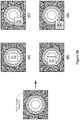
- FIG. 5Bshows a plurality of efficiency maps corresponding to various embodiments when the receiver is placed over different regions of a transmitter in accordance with some embodiments.
- FIG. 6Ais a flow diagram showing a process of detecting a receiver by sending beacon signals periodically in accordance with some embodiments.
- FIG. 6Bis a flow diagram showing a process of optional training performed by a transmitter in accordance with some embodiments.
- FIG. 7is a flow diagram showing a process of collecting, storing, and analyzing ADC samples performed by a transmitter in accordance with some embodiments.
- FIG. 8Ais a flow diagram showing a process of analyzing ADC samples performed by a transmitter in accordance with some embodiments.
- FIG. 8Bis a flow diagram showing a process of evaluating zone status to determine whether there is a foreign object and/or a receiver in accordance with some embodiments.
- FIGS. 9A-9Bare flow diagrams showing a method of operating a near-field charging pad, in accordance with some embodiments.
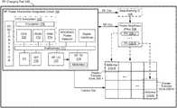
- FIG. 1Ais a block diagram of an RF wireless power transmission system 150 in accordance with some embodiments.
- the RF wireless power transmission system 150includes a RF charging pad 100 (also referred to herein as a near-field (NF) charging pad 100 or RF charging pad 100 ).
- the RF charging pad 100includes an RF power transmitter integrated circuit 160 (described in more detail below).
- the RF charging pad 100includes one or more communications components 204 (e.g., wireless communication components, such as WI-FI or BLUETOOTH radios), discussed in more detail below with reference to FIG. 2A .
- the RF charging pad 100also connects to one or more power amplifier units 108 - 1 , . .
- RF poweris controlled and modulated at the RF charging pad 100 via switch circuitry as to enable the RF wireless power transmission system to send RF power to one or more wireless receiving devices via the TX antenna array 210 .
- the communication component(s) 204enable communication between the RF charging pad 100 and one or more communication networks.
- the communication component(s) 204are capable of data communications using any of a variety of custom or standard wireless protocols (e.g., IEEE 802.15.4, Wi-Fi, ZigBee, 6LoWPAN, Thread, Z-Wave, Bluetooth Smart, ISA100.11a, WirelessHART, MiWi, etc.) custom or standard wired protocols (e.g., Ethernet, HomePlug, etc.), and/or any other suitable communication protocol, including communication protocols not yet developed as of the filing date of this document.
- custom or standard wireless protocolse.g., IEEE 802.15.4, Wi-Fi, ZigBee, 6LoWPAN, Thread, Z-Wave, Bluetooth Smart, ISA100.11a, WirelessHART, MiWi, etc.
- custom or standard wired protocolse.g., Ethernet, HomePlug, etc.
- the communication component(s) 204are not able to communicate with wireless power receivers for various reasons, e.g., because there is no power available for the communication component(s) to use for the transmission of data signals or because the wireless power receiver itself does not actually include any communication component of its own. As such, it is important to design near-field charging pads that are still able to uniquely identify different types of devices and, when a wireless power receiver is detected, figure out if that wireless power receiver is authorized to receive wireless power.
- FIG. 1Bis a block diagram of the RF power transmitter integrated circuit 160 (the “integrated circuit”) in accordance with some embodiments.
- the integrated circuit 160includes a CPU subsystem 170 , an external device control interface, an RF subsection for DC to RF power conversion, and analog and digital control interfaces interconnected via an interconnection component, such as a bus or interconnection fabric block 171 .
- the CPU subsystem 170includes a microprocessor unit (CPU) 202 with related Read-Only-Memory (ROM) 172 for device program booting via a digital control interface, e.g.
- CPUmicroprocessor unit
- ROMRead-Only-Memory
- the CPU subsystem 170also includes an encryption module or block 176 to authenticate and secure communication exchanges with external devices, such as wireless power receivers that attempt to receive wirelessly delivered power from the RF charging pad 100 .
- executable instructions running on the CPUare used to manage operation of the RF charging pad 100 and to control external devices through a control interface, e.g., SPI control interface 175 , and the other analog and digital interfaces included in the RF power transmitter integrated circuit 160 .
- the CPU subsystemalso manages operation of the RF subsection of the RF power transmitter integrated circuit 160 , which includes an RF local oscillator (LO) 177 and an RF transmitter (TX) 178 .
- LOlocal oscillator
- TXRF transmitter
- the RF LO 177is adjusted based on instructions from the CPU subsystem 170 and is thereby set to different desired frequencies of operation, while the RF TX converts, amplifies, modulates the RF output as desired to generate a viable RF power level.
- antenna zones and power-transfer zonesmay include antenna elements that transmit propagating radio frequency waves but, in other embodiments, the antenna/power transfer zones may instead include capacitive charging couplers that convey electrical signals but do not send propagating radio frequency waves.
- the RF power transmitter integrated circuit 160provides the viable RF power level (e.g., via the RF TX 178 ) to an optional beamforming integrated circuit (IC) 109 , which then provides phase-shifted signals to one or more power amplifiers 108 .
- the beamforming IC 109is used to ensure that power transmission signals sent using two or more antennas 210 (e.g., each antenna 210 may be associated with a different antenna zone 290 or may each belong to a single antenna zone 290 ) to a particular wireless power receiver are transmitted with appropriate characteristics (e.g., phases) to ensure that power transmitted to the particular wireless power receiver is maximized (e.g., the power transmission signals arrive in phase at the particular wireless power receiver).
- the beamforming IC 109forms part of the RF power transmitter IC 160 .
- capacitive couplerse.g., capacitive charging couplers 244
- optional beamforming IC 109may not be included in the RF power transmitter integrated circuit 160 .
- the RF power transmitter integrated circuit 160provides the viable RF power level (e.g., via the RF TX 178 ) directly to the one or more power amplifiers 108 and does not use the beamforming IC 109 (or bypasses the beamforming IC if phase-shifting is not required, such as when only a single antenna 210 is used to transmit power transmission signals to a wireless power receiver).
- the one or more power amplifiers 108then provide RF signals to the antenna zones 290 (also referred to herein as “power-transfer zones”) for transmission to wireless power receivers that are authorized to receive wirelessly delivered power from the RF charging pad 100 .
- each antenna zone 290is coupled with a respective PA 108 (e.g., antenna zone 290 - 1 is coupled with PA 108 - 1 and antenna zone 290 -N is coupled with PA 108 -N).
- multiple antenna zonesare each coupled with a same set of PAs 108 (e.g., all PAs 108 are coupled with each antenna zone 290 ).
- PAs 108to antenna zones 290 allow the RF charging pad 100 to sequentially or selectively activate different antenna zones in order to determine the most efficient antenna zone 290 to use for transmitting wireless power to a wireless power receiver (as explained in more detail below in reference to FIGS. 9A-9B, 10, and 11A-11E ).
- the one or more power amplifiers 108are also in communication with the CPU subsystem 170 to allow the CPU 202 to measure output power provided by the PAs 108 to the antenna zones of the RF charging pad 100 .
- FIG. 1Balso shows that, in some embodiments, the antenna zones 290 of the RF charging pad 100 may include one or more antennas 210 A-N.
- each antenna zones of the plurality of antenna zonesincludes one or more antennas 210 (e.g., antenna zone 290 - 1 includes one antenna 210 -A and antenna zones 290 -N includes multiple antennas 210 ).
- a number of antennas included in each of the antenna zonesis dynamically defined based on various parameters, such as a location of a wireless power receiver on the RF charging pad 100 .
- the antenna zonesmay include one or more of the meandering line antennas described in more detail below.
- each antenna zone 290may include antennas of different types (e.g., a meandering line antenna and a loop antenna), while in other embodiments each antenna zone 290 may include a single antenna of a same type (e.g., all antenna zones 290 include one meandering line antenna), while in still other embodiments, the antennas zones may include some antenna zones that include a single antenna of a same type and some antenna zones that include antennas of different types.
- the antenna/power-transfer zonesmay also or alternatively include capacitive charging couplers that convey electrical signals but do not send propagating radio frequency waves. Antenna zones are also described in further detail below.
- the RF charging pad 100may also include a temperature monitoring circuit that is in communication with the CPU subsystem 170 to ensure that the RF charging pad 100 remains within an acceptable temperature range. For example, if a determination is made that the RF charging pad 100 has reached a threshold temperature, then operation of the RF charging pad 100 may be temporarily suspended until the RF charging pad 100 falls below the threshold temperature.
- the RF power transmitter circuit 160may also include a secure element module 234 (e.g., included in the encryption block 176 shown in FIG. 1B ) that is used in conjunction with a secure element module 282 ( FIG. 2B ) or a receiver 104 to ensure that only authorized receivers are able to receive wirelessly delivered power from the RF charging pad 100 ( FIG. 1B ).
- a secure element module 234e.g., included in the encryption block 176 shown in FIG. 1B
- a secure element module 282FIG. 2B
- receiver 104to ensure that only authorized receivers are able to receive wirelessly delivered power from the RF charging pad 100 ( FIG. 1B ).
- FIG. 1Cis a block diagram of a charging pad 294 in accordance with some embodiments.
- the charging pad 294is an example of the charging pad 100 ( FIG. 1A ), however, one or more components included in the charging pad 100 are not included in the charging pad 294 for ease of discussion and illustration.
- the charging pad 294includes an RF power transmitter integrated circuit 160 , one or more power amplifiers 108 , and a transmitter antenna array 290 having multiple antenna zones. Each of these components is described in detail above with reference to FIGS. 1A and 1B . Additionally, the charging pad 294 includes a switch 295 (i.e., transmitter-side switch), positioned between the power amplifiers 108 and the antenna array 290 , having a plurality of switches 297 -A, 297 -B, . . . 297 -N. The switch 295 is configured to switchably connect one or more power amplifiers 108 with one or more antenna zones of the antenna array 290 in response to control signals provided by the RF power transmitter integrated circuit 160 .
- a switch 295i.e., transmitter-side switch
- each switch 297is coupled with (e.g., provides a signal pathway to) a different antenna zone of the antenna array 290 .
- switch 297 -Amay be coupled with a first antenna zone 290 - 1 ( FIG. 1B ) of the antenna array 290
- switch 297 -Bmay be coupled with a second antenna zone 290 - 2 of the antenna array 290 , and so on.
- Each of the plurality of switches 297 -A, 297 -B, . . . 297 -Nonce closed, creates a unique pathway between a respective power amplifier 108 (or multiple power amplifiers 108 ) and a respective antenna zone of the antenna array 290 .
- Each unique pathway through the switch 295is used to selectively provide RF signals to specific antenna zones of the antenna array 290 . It is noted that two or more of the plurality of switches 297 -A, 297 -B, . . . 297 -N may be closed at the same time, thereby creating multiple unique pathways to the antenna array 290 that may be used simultaneously.
- the RF power transmitter integrated circuit 160is coupled to the switch 295 and is configured to control operation of the plurality of switches 297 -A, 297 -B, . . . 297 -N (illustrated as a “control out” signal in FIGS. 1A and 1C ).
- the RF power transmitter integrated circuit 160may close a first switch 297 -A while keeping the other switches open.
- the RF power transmitter integrated circuit 160may close a first switch 297 -A and a second switch 297 -B, and keep the other switches open (various other combinations and configuration are possible).
- the RF power transmitter integrated circuit 160is coupled to the one or more power amplifiers 108 and is configured to generate a suitable RF signal (e.g., the “RF Out” signal) and provide the RF signal to the one or more power amplifiers 108 .
- the one or more power amplifiers 108are configured to provide the RF signal to one or more antenna zones of the antenna array 290 via the switch 295 , depending on which switches 297 in the switch 295 are closed by the RF power transmitter integrated circuit 160 .
- the charging padis configured to transmit test power transmission signals and/or regular power transmission signals using different antenna zones, e.g., depending on a location of a receiver on the charging pad. Accordingly, when a particular antenna zone is selected for transmitting test signals or regular power signals, a control signal is sent to the switch 295 from the RF power transmitter integrated circuit 160 to cause at least one switch 297 to close. In doing so, an RF signal from at least one power amplifier 108 can be provided to the particular antenna zone using a unique pathway created by the now-closed at least one switch 297 .
- the switch 295may be part of (e.g., internal to) the antenna array 290 .
- the switch 295is separate from the antenna array 290 (e.g., the switch 295 may be a distinct component, or may be part of another component, such as the power amplifier(s) 108 ). It is noted that any switch design capable of accomplishing the above may be used, and the design of the switch 295 illustrated in FIG. 1C is merely one example.
- FIG. 2Ais a block diagram illustrating certain components of an RF charging pad 100 in accordance with some embodiments.
- the RF charging pad 100includes an RF power transmitter IC 160 (and the components included therein, such as those described above in reference to FIGS. 1A-1B ), memory 206 (which may be included as part of the RF power transmitter IC 160 , such as nonvolatile memory 206 that is part of the CPU subsystem 170 ), and one or more communication buses 208 for interconnecting these components (sometimes called a chipset).
- the RF charging pad 100includes one or more sensor(s) 212 (discussed below).
- the RF charging pad 100includes one or more output devices such as one or more indicator lights, a sound card, a speaker, a small display for displaying textual information and error codes, etc.
- the RF charging pad 100includes a location detection device, such as a GPS (global positioning satellite) or other geo-location receiver, for determining the location of the RF charging pad 100 .
- GPSglobal positioning satellite
- the one or more sensor(s) 212include one or more thermal radiation sensors, ambient temperature sensors, humidity sensors, IR sensors, occupancy sensors (e.g., RFID sensors), ambient light sensors, motion detectors, accelerometers, and/or gyroscopes.
- the RF charging pad 100further includes a signature-signal receiving circuit 240 ( FIGS. 3A and 3E-3G ), a reflected power coupler 242 (e.g., FIGS. 3A and 3E ), and a capacitive charging coupler 244 ( FIG. 5A ).
- a signature-signal receiving circuit 240FIGS. 3A and 3E-3G
- a reflected power coupler 242e.g., FIGS. 3A and 3E
- a capacitive charging coupler 244FIG. 5A .
- the memory 206includes high-speed random access memory, such as DRAM, SRAM, DDR SRAM, or other random access solid state memory devices; and, optionally, includes non-volatile memory, such as one or more magnetic disk storage devices, one or more optical disk storage devices, one or more flash memory devices, or one or more other non-volatile solid state storage devices.
- the memory 206or alternatively the non-volatile memory within memory 206 , includes a non-transitory computer-readable storage medium.
- Each of the above-identified elementsis optionally stored in one or more of the previously mentioned memory devices, and corresponds to a set of instructions for performing the function(s) described above.
- the above identified modules or programse.g., sets of instructions
- the memory 206optionally, stores a subset of the modules and data structures identified above.
- FIG. 2Bis a block diagram illustrating a representative receiver device 104 (also sometimes called a receiver, power receiver, or wireless power receiver) in accordance with some embodiments.
- the receiver device 104includes one or more processing units (e.g., CPUs, ASICs, FPGAs, microprocessors, and the like) 252 , one or more communication components 254 , memory 256 , antenna(s) 260 , power harvesting circuitry 259 , and one or more communication buses 258 for interconnecting these components (sometimes called a chipset).
- the receiver device 104includes one or more sensor(s) 262 such as the one or sensors 212 described above with reference to FIG. 2A .
- the receiver device 104includes an energy storage device 261 for storing energy harvested via the power harvesting circuitry 259 .
- the energy storage device 261includes one or more batteries, one or more capacitors, one or more inductors, and the like.
- the power harvesting circuitry 259includes one or more rectifying circuits and/or one or more power converters. In some embodiments, the power harvesting circuitry 259 includes one or more components (e.g., a power converter) configured to convert energy from power waves and/or energy pockets to electrical energy (e.g., electricity). In some embodiments, the power harvesting circuitry 259 is further configured to supply power to a coupled electronic device, such as a laptop or phone. In some embodiments, supplying power to a coupled electronic device include translating electrical energy from an AC form to a DC form (e.g., usable by the electronic device).
- a coupled electronic devicesuch as a laptop or phone. In some embodiments, supplying power to a coupled electronic device include translating electrical energy from an AC form to a DC form (e.g., usable by the electronic device).
- the signature-signal generating circuit 315includes one or more components as discussed with reference to FIGS. 3A-3D .
- the antenna(s) 260include one or more of the meandering line antennas that are described in further detail below.
- the antenna(s) 260may also or alternatively include capacitive charging couplers that correspond in structure to those that may be present in a near-field charging pad.
- the receiver device 104includes one or more output devices such as one or more indicator lights, a sound card, a speaker, a small display for displaying textual information and error codes, etc.
- the receiver device 104includes a location detection device, such as a GPS (global positioning satellite) or other geo-location receiver, for determining the location of the receiver device 103 .
- GPSglobal positioning satellite
- the one or more sensor(s) 262include one or more thermal radiation sensors, ambient temperature sensors, humidity sensors, IR sensors, occupancy sensors (e.g., RFID sensors), ambient light sensors, motion detectors, accelerometers, and/or gyroscopes.
- the communication component(s) 254enable communication between the receiver 104 and one or more communication networks.
- the communication component(s) 254are capable of data communications using any of a variety of custom or standard wireless protocols (e.g., IEEE 802.15.4, Wi-Fi, ZigBee, 6LoWPAN, Thread, Z-Wave, Bluetooth Smart, ISA100.11a, WirelessHART, MiWi, etc.) custom or standard wired protocols (e.g., Ethernet, HomePlug, etc.), and/or any other suitable communication protocol, including communication protocols not yet developed as of the filing date of this document.
- custom or standard wireless protocolse.g., IEEE 802.15.4, Wi-Fi, ZigBee, 6LoWPAN, Thread, Z-Wave, Bluetooth Smart, ISA100.11a, WirelessHART, MiWi, etc.
- custom or standard wired protocolse.g., Ethernet, HomePlug, etc.
- the communication component(s) 254include, for example, hardware capable of data communications using any of a variety of custom or standard wireless protocols (e.g., IEEE 802.15.4, Wi-Fi, ZigBee, 6LoWPAN, Thread, Z-Wave, Bluetooth Smart, ISA100.11a, WirelessHART, MiWi, etc.) and/or any of a variety of custom or standard wired protocols (e.g., Ethernet, HomePlug, etc.), or any other suitable communication protocol, including communication protocols not yet developed as of the filing date of this document.
- custom or standard wireless protocolse.g., IEEE 802.15.4, Wi-Fi, ZigBee, 6LoWPAN, Thread, Z-Wave, Bluetooth Smart, ISA100.11a, WirelessHART, MiWi, etc.
- any of a variety of custom or standard wired protocolse.g., Ethernet, HomePlug, etc.
- the memory 256includes high-speed random access memory, such as DRAM, SRAM, DDR SRAM, or other random access solid state memory devices; and, optionally, includes non-volatile memory, such as one or more magnetic disk storage devices, one or more optical disk storage devices, one or more flash memory devices, or one or more other non-volatile solid state storage devices.
- the memory 256or alternatively the non-volatile memory within memory 256 , includes a non-transitory computer-readable storage medium.
- Each of the above-identified elementsis optionally stored in one or more of the previously mentioned memory devices, and corresponds to a set of instructions for performing the function(s) described above.
- the above identified modules or programse.g., sets of instructions
- the memory 256optionally, stores a subset of the modules and data structures identified above.
- the memory 256optionally, stores additional modules and data structures not described above, such as an identifying module for identifying a device type of a connected device (e.g., a device type for an electronic device that is coupled with the receiver 104 ).
- the near-field charging pads disclosed hereinmay use adaptive loading techniques to optimize power transfer. Such techniques are described in detail in commonly-owned PCT Application No. PCT/US17/65886 and, in particular, in reference to FIGS. 3A-8 and 12-15 , and the disclosures in this commonly-owned application is hereby expressly incorporated by reference in its entirety.
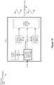
- FIG. 3Ais a block diagram of simplified circuits of an example wireless power-transfer zone 300 (e.g., one of the plurality of power-transfer zones 290 A-N, FIG. 1B ) located at the RF charging pad 100 , and an example wireless power receiver 305 (e.g., an instance of the receiver 104 , FIG. 2B ), in accordance with some embodiments.
- the wireless power receiver 305includes a signature-signal generating circuit 315 , as discussed with reference to FIGS. 3B-3D .
- the power-transfer zone 300may be referred to below, or illustrated in the Figures, as a transmitter (TX).
- an oscillator on the receiver device 305includes one or more elements configured to control duty cycle and frequency and modulate a variable load 310 at the rectifier DC output port.
- the rectifier voltageis encoded as frequency
- the rectifier load currentis encoded as duty cycle (or vice versa).
- the host 320e.g., CPU
- the receiver 305includes a power-link monitoring chip with interfaces to the host 320 and the rectifier 306 , and the power-link monitoring chip can also control the frequency/duty cycle of the oscillator.
- the frequency and duty cycle variationsare analyzed to recognize whether there are any foreign objects on the RF charging pad 100 (e.g., between the RF charging pad 100 and the receiver device 305 on top of the RF charging pad 100 ).
- the DC load modulationvaries the impedance at the antenna interface 303 between the power-transfer zone 300 and the receiver 305 .
- the impedance changecauses variations in reflected power (e.g., reflected power 340 , FIG. 3B-1 ) at the receiver block 240 residing on the power-transfer zone 300 , and such receiver block 240 decodes the variations to identify the reflected signals including information related to frequency and duty cycle (e.g., frequency and duty cycle are shown in FIG. 3E ).
- the rectifier loading conditionsare known at the power-transfer zone 300 .
- oscillator/modulatorare enabled/disabled based on (1) configurable (voltage) threshold on rectifier DC output and/or (2) firmware control.
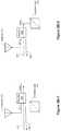
- FIGS. 3B-1 and 3B-2show block diagrams illustrating circuits including a rectifier 306 coupled to a variable load 310 of a receiver device (e.g., receiver device 305 , FIG. 3A ), in accordance with some embodiments.
- the rectifier 306converts RF power received at the RFin port into DC power at the Vrect port.
- the amount of power receivedis dependent on the amount of power input by the antenna 313 (e.g., antenna(s) 260 , FIG. 2B ) of the receiver 305 and the impedance match between the antenna 313 of the receiver 305 and the rectifier 306 .
- the impedances of the antenna 313 and the rectifier 306when the impedances of the antenna 313 and the rectifier 306 are matched, substantially all of the power from the antenna 313 enters the rectifier 306 and substantially none of the power is reflected (illustrated by lines 341 in FIGS. 3B-1 and 3B-2 ).
- the impedances of the antenna 313 and the rectifier 306are not matched, then some power from the antenna 313 is reflected off the rectifier 306 and the reflected power signals 310 are transmitted back to the antenna 313 (illustrated by lines 340 in FIGS. 3B-1 and 3B-2 ).
- the reflected power 340is a source of system inefficiency in that it reduces the total amount of DC power that could be obtained from an available amount of RF power.
- reflecting all, or a substantial portion, of the RF input powercan be useful if no power is intended to be received at the receiver device 305 . For example, if the host 320 battery is full, then the received power must be dissipated as heat somewhere in the receiver 305 . Therefore, in some embodiments, it can be more thermally effective to reflect that power back out of the antenna 313 .
- the reflected power signals 340can be modulated for the purposes of data communications, as referred to as “load modulation” and this can be accomplished in some embodiments by placing a variable load 310 at the rectifier RFin port ( FIG. 3B-1 ).
- the amount of power reflectedis controlled by a variable load 310 located at the RF input ( FIG. 3B-1 ).
- This type of controlhas disadvantages: even when OFF, the variable load 310 introduces a loss at the RF frequency and therefore reduces the RF to DC conversion efficiency.
- very high Q bandpass filtersare needed to filter the modulation spectrum for regulatory compliance.
- Controlling the amount of reflected power 340may also be used for conveying data to a signature-signal receiving circuit 240 (e.g., included in a respective power-transfer zone of an RF charging pad).
- the signature-signal receiving circuit 240is a universal circuit for the NF charging pad 100 (i.e., the NF charging pad 100 includes a single signature-signal receiving circuit 240 that services each of the power-transfer zones 290 ).
- each of the power-transfer zonese.g., zone 300
- each of the power-transfer zonesincludes its own signature-signal receiving circuit 240 (as shown in FIG. 3A ).
- the inventorshave determined that it is advantageous to locate the variable load 310 at the Vrect port (DC side) of the rectifier 306 ( FIG. 3B-2 ), as is discussed in more detail below.
- the variable load 310can be moved to the DC side of the rectifier 306 ( FIG. 3B-2 ).
- the rectifier 306thus operates both as a downconverter (converting RF power to DC power) and an upconverter (converting the load modulation at Vrect to the RF frequency at RFin).
- having the variable load 310 located at the DC side of the rectifier 306solves disadvantages mentioned above that are present when the variable load 310 is placed at the RFin port.
- FIG. 3Cis a block diagram illustrating circuits including a reflect switch 311 within a wireless power receiver 305 (pictured in FIG. 3A ) in accordance with some embodiments.
- a reflect switch 311is used to reflect all, or a substantial portion, of the received power.
- the reflect switch 311could be located at the RFin port, however this would present the same disadvantages as discussed with reference to FIG. 3B-1 , which illustrates an example of the variable load 310 coupled to the Rfin port.
- these disadvantagesare largely mitigated by placing the reflect switch 311 at the DC port (e.g., the Vrect port) of the rectifier 306 .
- the reflect switch 311when the reflect switch 311 is OFF, the reflect switch 311 does nothing.
- the reflect switch 311When the reflect switch 311 is ON, it presents a very low impedance (e.g., a short circuit) load at the DC side of the rectifier 306 .
- a low impedance loadis seen at the RFin port of the rectifier 306 , which presents a substantial impedance mismatch between the antenna 313 and the rectifier 306 . Therefore, when the reflect switch 311 is ON, a substantial percentage of the input power from the antenna 313 is reflected back out of the antenna 313 and does not get converted to DC power by the rectifier 306 .
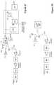
- FIG. 3Dis a block diagram illustrating an example of a signature-signal generating circuit 315 of the wireless power receiver 305 in accordance with some embodiments.
- the signature-signal generating circuit 315includes a PFM/PWM (pulse-frequency modulation/pulse-width modulation) generator 309 to control the variable load 310 for generating a valid receiver “signature” (also referred to herein as a signature signal).
- the signature-signal generating circuit 315further includes (or is in communication with) a window comparator 307 to disable the control scheme unless sufficient power is available at Vrect to turn on all the circuitry.
- the signature-signal generating circuit 315further includes a current sensor 308 that converts the rectifier load current into a voltage which is received by the PFM/PWM generator 309 .
- the PFM/PWM generator 309also senses Vrect directly.
- the reflect switch 311is also part of the signature-signal generating circuit 315 .
- the window comparator 307 , current sensor 308 , and PFM/PWM generator 309 , and any other auxiliary circuitrycan be powered by power signals that are transmitted from the power-transfer zone 300 , rectified by the rectifier 306 , and supplied from the Vrect port, such that the system is independent of the host battery.
- the signature-signal generating circuit 315 in the receiver device 305can still be powered by the power signals received from the power-transfer zone 300 to generate signals with signatures.
- Such signals with signaturesare further reflected back to the power-transfer zone 300 for sampling and analyzing whether there is any foreign object placed between the power-transfer zone 300 and the receiver 305 , and/or whether the receiver 305 is authorized to receive power from the power-transfer zone 300 (or the charging pad 100 in general).
- the PWM/PFM generator 309converts the current sense and voltage sense inputs to a pulse train where the pulse frequency is dependent on the sensed current and the pulse width is dependent on the sensed voltage (or vice versa).
- the pulse trainis applied to the variable load 310 , which therefore represents a pulsed load at the port Vrect, and this pulsed load is upconverted to RF by the rectifier 306 as previously explained.
- the pulsed loadwill be sensed by the power-transfer zone 300 for sampling and analyzing.
- FIG. 3Eillustrates a block diagram that shows an example power-transfer zone 300 including a signature-signal receiving circuit 240 in accordance with some embodiments.
- the coupling network impedanceis sensed by the reflected power coupler 242 .
- the reflected power coupler 242is used to measure the impedance being reflected back from the receiver 305 to the antenna 302 (e.g., antenna 210 , FIG. 1B ) of the power-transfer zone 300 .
- the antenna 302e.g., antenna 210 , FIG. 1B
- some power signalsare being reflected by the receiver 305 .
- a portion of such reflected power signals 340is received at the power-transfer zone 300 's antenna 302 , and the impedance is measured by the reflected power coupler 242 at the power-transfer zone 300 .
- the power-transfer zone 300can determine an extent of a mismatch between the power-transfer zone 300 and the receiver 305 . For example, if 1/10 of the reflected power 340 received at the power-transfer zone 300 can be sensed by the reflected power coupler 242 , and when 1/10 of the original transmitted power is received at the reflected power coupler 242 , it can be determined that the receiver 305 does not take any power signals from the power-transfer zone 300 .
- the reflected power signals 340 received from the receiver 305are processed and analyzed by the signature-signal receiving circuit 240 .
- the received reflected signal 340is amplified, filtered, and demodulated using an amplitude modulator (AM) detector 350 .
- AMamplitude modulator
- AGCautomatic gain control
- the digitally-sampled signalsare matched with antenna fingerprint, e.g., by data analysis block 356 .
- the rectifier loading conditionsare sensed.
- Message IDis decoded from the received reflected signals as further shown in FIG. 4 (and discussed further below).
- FIGS. 3F-3Hshow respective block diagrams illustrating various example circuits of power-transfer zones 300 and wireless receivers 305 in accordance with some embodiments.
- the pulsed load at RFinmodulates the amount of reflected power 340 which propagates out of an antenna 313 of the wireless power receiver 305 .
- some of this reflected powerenters the transmitting antenna 302 (also referred to as a “power-transferring element”), and some of that in turn is coupled into the receive port of the load-modulation receiver on the power-transmitter unit.
- the reflected poweris received using an AM receiver topology with variable gain stages and AGC for optimal SNR adjustment.
- a foreign object 360is placed on the receiver 305 , there is also reflected power from the surface of the foreign object 360 , which is also sensed by the AM receiver 350 .
- the received data streamis analyzed to extract the receiver signature waveform (its “signature signal”).
- the signature signalis the PWM/PFM pulse train previously described.
- the power-transfer zone 300can determine the system state from among the following options: 1) no object on top, 2) one or more foreign objects on top, 3) valid receiver only, and 4) foreign object in between receiver and a surface of the RF charging pad.
- the power-transfer zone 300may apply several power levels and measure changes in the PWM/PFM pulse train to authenticate an authorized receiver.
- other messagesmay be passed from the receiver 305 to the power-transfer zone 300 using the “control” pin(s) which can modify load modulation.
- the messages received by the power-transfer zone 300can be sampled and analyzed to obtain informing regarding receiver conditions, such as battery status (e.g., full/dead/other), temperature, rectifier voltage/current, and future intended actions such as intention to turn on the reflect switch 311 .
- the transmission of power signalscoexists with other wireless protocols. For example, if the host 320 intends to send or receive wireless (Bluetooth, WiFi, LTE, etc.) traffic but cannot because the power-transfer zone 300 is on and is interfering with the Bluetooth system, the host 320 may wish to stop the power-transmission for an interval to clear the wireless traffic, and then continue the power-transmission.
- wirelessBluetooth, WiFi, LTE, etc.
- Techniques for managing coexistence of power and data signalsare described in commonly-owned U.S. Provisional Patent Application 62/579,049, filed on Oct. 30, 2017, which is hereby incorporated by reference in its entirety.
- the host 320(shown in FIG. 3H ) can obtain control of the load modulation using the “control” input. In some embodiments, the host 320 can force certain PWM/PFM combinations which are then interpreted as pre-defined messages by the power-transfer zone 300 . Examples of such pre-defined messages are discussed with reference to FIG. 4 below.
- the host 320controls the reflect switch 311 .
- Vrectis drawn below the window comparator threshold and the PWM/PFM 309 stops.
- the power-transfer zone 300detects the absence of a valid receiver signature.
- the actions under this scenarioare programmable per application.
- a switch 312i.e., receiver-side switch
- to the host power inputis controlled via the host 320 and also via the window comparator 307 such that the host 320 cannot overload the rectifier 306 during system startup.
- FIG. 4lists example messages encoded using signature signals in PFM/PWM pairs, in accordance with some embodiments.
- the Frequency/duty pairsalso PFM/PWM pairs
- FIG. 4lists an example plot of 42 frequency/duty pairs, and each pair has a different meaning used to control the power transfer link, implementing coexistence and foreign object detection (FOD).
- the PFM/PAM pairs shown in A0-A6are decoded as a request from the receiver 305 to the power-transfer zone 300 to reduce power by various amounts.
- the PFM/PAM pairs shown in B0-B6are decoded as a request from the receiver 305 to the power-transfer zone 300 to increase power by various amounts.
- the PFM/PAM pairs shown in C0-C6are decoded as a request from the receiver 305 to the power-transfer zone 300 to stop transmitting for various lengths of time then restart, or stop forever.
- FIG. 5Aillustrates a simplified diagram showing a highly-coupled near-field capacitive coupler 244 (e.g., FIG. 2A ) that is used in a power-transfer zone 300 in accordance with some embodiments (e.g., the coupler 244 can be the antenna 302 discussed above with reference to FIGS. 3A-3H ).
- the highly-coupled near-filed capacitive coupler 244is coupled to the power amplifier 108 and the signature-signal receiving circuit 240 ( FIG. 3A ).
- the highly-coupled near-field capacitive coupler 244operates in one of the ISM frequency bands. In some embodiments, no electromagnetic (EM) propagation occurs in the current system.
- EMelectromagnetic
- the wireless poweris transmitted and received via capacitive coupling elements between the power-transfer zone 300 and the receiver 305 .
- the capacitive couplingoccurs when two coupling elements (one on transmitter side and one on receiver side) are placed in front of each other in an optimum position when desired stackup is placed between two coupling elements.
- the center coupler 502 and parasitic elements 504there is no limit on the shape, size, and number of the center coupler 502 and parasitic elements 504 .
- the parasitic elements 504can be in the same level as the center coupling element 502 or at a higher or a lower level from the center coupling element 502 .
- the parasitic elements 504are placed around the center coupling element 502 to extend X-Y coverage within the planar area of the capacitive coupler 244 .
- the systemis formed as a two-conductor capacitor.
- the parasitic elements 504are effective in forming a multi-conductor capacitive system to maximize the power transfer from the power-transfer zone 300 to the receiver 305 .
- the coupler circuitry 242in a form of a chip or printed lines, as shown in FIG. 3A ) to sample the reflected RF power signals 340 .
- the capacitive charging coupler 244includes a reflecting plane.
- the systemwhen the receiver antenna 313 is placed on top of the transmitting antenna 302 (e.g., one of the capacity charging couplers 244 ), the system shows coupling efficiency of more than a predetermined threshold value (e.g., a minimum acceptable value, such as 70%).
- a predetermined threshold valuee.g., a minimum acceptable value, such as 70%.
- the transmitting antenna 302 and receiver antenna 313are completely standalone, the system is mismatched. As soon as these antennas are placed on top of each-other, both antennas get matched. In some embodiments, the coupling system only works when the designed receiver is placed on top of the transmitting antenna 302 . In case of a foreign object 360 being placed on top of the power-transfer zone 300 , the transmitting antenna 313 is not matched. Such mismatch induced by a foreign object 360 can be used to detect a foreign object 360 placed between the power-transfer zone 300 and the receiver 305 .
- the coupling between the receiver 305 and the power-transfer zone 300reaches a peak when the receiver antenna 313 and the transmitting antenna 302 are fully aligned/centered (e.g. 90%). In some embodiments, as the receiver antenna 313 moves over the transmitting antenna 302 , the coupling performance drops, but it remains within an acceptable range (e.g. stays within 70-90%). In some embodiments, when receiver antenna 313 moves outside the minimum coupling range (e.g. 70%), the second/adjacent transmitting antenna 302 gets activated for a smooth transition.
- both transmitter and receiver antennasare mismatched, and when the correct placement occurs, both transmitting antenna 302 and receiver antenna 313 get matched and the maximum power can be obtained from transmitting antenna 302 to receiver antenna 313 .
- highly-coupled near field antenna pairsonly work in presence of each other. Therefore, in presence of other types of receiver antennas and/or any other foreign objects, the transmitting antenna 302 stays mismatched.
- FIG. 5Bshows a plurality of efficiency maps corresponding to various embodiments when the receiver 305 is placed over different regions of a power-transfer zone 300 that includes one or the couplers 244 in accordance with some embodiments.
- highly-coupled antenna pairscan be treated as state-machines.
- the power-transfer zone 300includes multiple areas with respective charging efficiencies when a receiver 305 is displaced on top of the corresponding areas.
- the matching of both the receiver 305 and power-transfer zone 300is better than ⁇ 15 dB.
- the matching of both the receiver 305 and power-transfer zone 300is in a range of ⁇ 10 dB to ⁇ 15 dB.
- the receiver 305is placed on top of the cross-hatched zone (70% ⁇ efficiency ⁇ 80%) of the power-transfer zone 300 (C—top-right map)
- the matching of both the receiver 305 and power-transfer zone 300is in a range of ⁇ 5 dB and ⁇ 10 dB.
- the receiver 305is placed on top of the darker zone (efficiency ⁇ 70%) of the power-transfer zone 300 (D—bottom-right map)
- the matching of both the receiver 305 and power-transfer zone 300is worse than ⁇ 5 dB.
- FIG. 6Ais a flow diagram 600 showing a process of detecting a receiver 305 by sending beacon signals (also referred to herein as “test power transmission signals”) periodically in accordance with some embodiments.
- each power-transfer zonestarts ( 602 ) a timer so as to send beacon signals periodically.
- each power-transfer zone of the NF charging padalso referred to herein as an RF charging pad
- the signature-signal generating circuit 315 of the receiver 305e.g., as discussed in FIGS. 3A and 3E ) can generate signature-signals based on the beacon signal.
- each power-transfer zonereceives ( 608 ) the receiver 305 generated signature-signals and collects analog-to-digital converter 354 (ADC) samples.
- ADCanalog-to-digital converter 354
- the transmitter beacon signalis disabled ( 610 ), the samples from ADC 354 are analyzed ( 612 ), and the zone status is evaluated ( 614 ) (e.g., as discussed with reference to FIG. 5B ).
- the timeris restarted ( 616 ) to start the next period for sending beacon signals.
- the start step ( 602 )includes an optional training process as discussed with reference to FIG. 6B (and in more detail below in reference to FIG. 9A ).
- FIG. 6Bis a flow diagram 650 showing a process of optional training performed by the power-transfer zone 300 in accordance with some embodiments.
- optional trainingis an embodiment for aiding foreign object detection (FOD) using signature-signal-based detection. In some embodiments, this can be done at one time with known sets of receivers and FOD devices.
- FODforeign object detection
- enough ADC samplesare collected ( 652 ) to enable classification of FOD, and the derived parameters provide the ability to classify the object detection status including (1) no object present ( 654 ), (2) one or more foreign objects present ( 654 ), (3) receiver only present ( 658 ), and (4) foreign object in between receiver 305 and power-transfer zone 300 ( 660 ).
- the processfurther includes analyzing ( 662 ) ADC samples to derive FOD parameters, and storing ( 664 ) the FOD in memory (e.g., in non-volatile memory). More details regarding example training/learning processes are described below in reference to FIG. 9A .
- FIG. 7is a flow diagram 700 showing a process of collecting, storing, and analyzing ADC samples performed by the power-transfer zone 300 in accordance with some embodiments.
- collecting the ADC samplesbegins at a step 702 , and sampling may continue as a preconfigured tight loop in firmware.
- firmwareruns an optimized loop to collect and store the ADC data in a buffer, which includes enabling ( 704 ) the ADC block, initializing ( 706 ) the buffer, reading ( 708 ) the ADC for data, storing ( 710 ) the collected data (e.g., ADC samples) in the buffer.
- firmwareruns an optimized loop to collect and store the ADC data in a buffer, which includes enabling ( 704 ) the ADC block, initializing ( 706 ) the buffer, reading ( 708 ) the ADC for data, storing ( 710 ) the collected data (e.g., ADC samples) in the buffer.
- it is determined whether all the ADC samples are collected( 712 ).
- the process 700loops back to the reading the ADC (step 708 ). This can be subjected to timing variation and result in inaccuracies. These variations can be minimized by collecting samples multiple times and averaging to remove the noise.
- operation 702is hardware (HW) assisted. For example, at operation 702 harward is used to sample the ADC values at fixed intervals in a pre-defined buffer. Once all the samples are collected, firmware will be notified and subsequent operations shown in FIG. 7 may continue. This guarantees tight timing for sampling and gives more accurate result. Also the firmware is not blocked in a dead loop of collecting samples.
- HWhardware
- FIG. 8Ais a flow diagram 800 showing a process of analyzing ADC samples performed by a power-transfer zone 300 in accordance with some embodiments.
- a baseline of the collected ADC samplesis determined.
- the average of the collected ADC samplesis determined ( 802 ).
- each ADC sampleis compared against the determined baseline, e.g., the average of the collected ADC samples ( 804 ).
- a high-countis incremented ( 806 ).
- an ADC sampleis lower than the calculated average ( 804 —No)
- a low-countis incremented ( 808 ).
- a duty cycleis calculated ( 810 ) by: high-count/(high-count+low-count), and a frequency is calculated ( 812 ) using time between edges of Fast Fourier transform (FFT).
- FFTFast Fourier transform
- FIG. 8Bis a flow diagram 820 showing a process of evaluating zone status ( 814 ) to determine whether there is a foreign object and/or a receiver present in accordance with some embodiments.
- the calculated frequency and duty cycleare compared ( 822 ) against factory-calibrated data. It is then determined whether only a receiver is present ( 824 ). In accordance with a determination that only a receiver is present ( 824 —Yes), the presence of the receiver is reported ( 832 ) and the charging of the receiver by the antenna zone (e.g., by the power-transfer zone 300 ) is enabled ( 834 ).
- the systemwaits ( 836 ) for the receiver to connect over Bluetooth. When the receiver is connected over Bluetooth ( 836 —Yes), the wireless power signals are acquired from the transmitter power control ( 838 ). When the receiver is not connected over Bluetooth ( 836 —No), the charging of the receiver is disabled ( 840 ).
- a receiverwhen it is determined that a receiver is present, it is also determined whether a foreign object is present with the receiver. In some embodiments, when a receiver 305 and a foreign object 360 are identified ( 826 ), the charging of the receiver with the foreign object is allowed ( 831 ); and, then the charging process can be enabled. In some embodiments, when only foreign object is detected ( 828 ), the presence of the foreign object is reported ( 829 ). In some embodiments, when no foreign object is detected, it is determined that no object ( 830 ), e.g., neither a receiver nor a foreign object, is present.
- FIGS. 9A-9Bare flow diagrams showing a method 900 of operating a near-field charging pad, in accordance with some embodiments.
- Operations of the method 900are performed by a near-field charging pad (e.g. RF charging pad 100 , FIGS. 1B and 2A ) or by one or more components thereof (e.g., those described above with reference to FIGS. 1A-1B and 2A ).
- the method 900corresponds to instructions stored in a computer memory or computer-readable storage medium (e.g., memory 206 of the RF charging pad 100 , FIG. 2A ).
- the near-field charging padincludes one or more processors (e.g., CPU 202 , FIG. 1B ), a wireless communication component (e.g., communication component(s) 204 , FIGS. 1A and 2A ), and a plurality of power-transfer zones (e.g., antenna zones 290 - 1 and 290 -N, FIG. 1B ; power-transfer zone 300 , FIG. 3A ) that each respectively include at least one power-transferring element (e.g., one of antennas 210 , FIG. 2A , which may be one of the antennas 120 described in reference to FIGS. 3A-6E in commonly-owned PCT Application No.
- processorse.g., CPU 202 , FIG. 1B
- a wireless communication componente.g., communication component(s) 204 , FIGS. 1A and 2A
- a plurality of power-transfer zonese.g., antenna zones 290 - 1 and 290 -N, FIG. 1
- the antennas 210may also be one or more of the capacitive couplers 244 described above in reference to FIG. 5A ) and a signature-signal receiving circuit (e.g., the circuit 240 described above in reference to FIGS. 2A, 3A and 3E-3H , and the signature-signal receiving circuit may also include a reflected power coupler 242 ) ( 902 ).
- a signature-signal receiving circuite.g., the circuit 240 described above in reference to FIGS. 2A, 3A and 3E-3H , and the signature-signal receiving circuit may also include a reflected power coupler 242 ) ( 902 ).
- the near-field charging padincludes distinct power-transferring elements that are each included in respective power-transfer zones.
- an antenna zone 290 - 1includes an antenna 210 -A.
- an antenna zone 290 -Nincludes multiple antennas.
- the antenna zonesmay also be referred to as antenna groups, such that the near-field charging pad includes a plurality of antenna/power-transfer zones or groups, and each respective zone/group includes at least one of the distinct antenna elements (e.g., at least one antenna 210 ).
- an antenna/power-transfer zonecan include any number of antennas, and that the numbers of antennas associated with a particular antenna/power-transfer zone may be modified or adjusted (e.g., the CPU subsystem 170 of RF power transmitter integrated circuit 160 responsible for managing operations of the near-field charging pad 100 dynamically defines each antenna/power-transfer zone at various points in time).
- each antenna/power-transfer zoneincludes a same number of antennas/power-transferring elements.
- the one or more processorsare a component of a single integrated circuit (e.g., RF power transmitter integrated circuit 160 , FIG. 1B ) that is used to control operation of the near-field charging pad.
- the one or more processors and/or the wireless communication component of the near-field charging padis/are external to the near-field charging pad, such as one or more processors of a device in which the near-field charging pad is embedded.
- the wireless communication componentis a radio transceiver (e.g., a BLUETOOTH radio, WI-FI radio, or the like for exchanging communication signals with wireless power receivers).
- the method 900includes optionally learning ( 904 ) signature signals for different wireless power receivers (e.g., receiver 305 , FIG. 3A ) and for other objects (e.g., foreign object 360 , FIG. 3G ), and these learned signature signals are stored in a data source (which may be a local memory of the near-field charging pad or which may be hosted externally to the near-field charging pad).
- a data sourcewhich may be a local memory of the near-field charging pad or which may be hosted externally to the near-field charging pad.
- the one or more processors of the near-field charging padare in communication with the data source into which each of the learned signature signals is stored.
- the data sourcemay be hosted internally or externally to the near-field charging pad.
- the data sourceis populated with the one or more predefined signature signals during a configuration process in which each of a plurality of different wireless power receivers is placed on the near-field charging pad to allow the near-field charging pad to detect and then store (in the data source) a respective predefined signature signal for each of the plurality of different wireless power receivers.
- a usermay provide an indication as to whether the respective wireless power receiver is an authorized wireless power receiver or not. In this way, the near-field charging pad is able to learn signature signals for both authorized and unauthorized wireless power receivers.
- the configuration processalso includes placing a plurality of different objects (e.g., keys, coins, various types of liquids, credits cards, coffee mugs, or any other type of household object that a user might place on the near-field charging pad), which are not wireless power receivers, on the near-field charging pad to allow the near-field charging pad to detect and then store (in the data source) a respective predefined signature signal for each of the plurality of different objects.
- a plurality of different objectse.g., keys, coins, various types of liquids, credits cards, coffee mugs, or any other type of household object that a user might place on the near-field charging pad
- a plurality of different objectse.g., keys, coins, various types of liquids, credits cards, coffee mugs, or any other type of household object that a user might place on the near-field charging pad
- a plurality of different objectse.g., keys, coins, various types of liquids, credits cards, coffee mugs, or any other type of household
- identifiers for each of the different objectsare also stored with each of the respective stored signature signals, thereby allowing the near-field charging pad to identify different types of objects based on matching a signature signal to one of the stored signals.
- signature signalsare also learned for combinations of the different wireless power receivers and the plurality of different objects (e.g., each of the different objects may be placed underneath or on top of each of the different wireless power receivers), and these signature signals are also stored in the data source.
- Certain implementations of the near-field charging padmay be implemented so that detection of one of the different objects causing the near-field charging pad to cease any transmission of power. In this way, potential damage to any of the different objects may be avoided.
- the method 900also includes sending ( 906 ), by a respective power-transferring element included in a first power-transfer zone of the plurality of power-transfer zones, a plurality of test power transmission signals (also termed beacon power transmission signals) with first values for a first set of transmission characteristics.
- the first values for the first set of transmission characteristicsinclude a power level for each of the plurality of test power transmission signals that is less than a certain power threshold (e.g., 30 dB).
- the sending operation 906is performed based on a predefined time interval, such that at every predefined time interval the test power transmission signals are sent by the first power-transfer zone.
- the predefined time intervalis 1 second, 2 seconds, or 5 seconds, or some value therebetween.
- the near-field charging padincludes a data-communication radio (e.g., a wireless communication component 254 , such as a BLUETOOTH radio), and the sending of the plurality of test power transmission signals is performed without receiving any signal via the data-communication radio.
- the method 900is used to detect that an authorized receiver is present on the near-field charging pad even when that receiver has no charge in its power sources (e.g., its battery is completely drained). Additionally, the method 900 is also used to detect authorized receivers on the pad which do not have any data-communication radios at all.
- the methodalso includes detecting ( 908 ), using the signature-signal receiving circuit, respective amounts of reflected power (e.g., reflected signals 340 , FIG. 3F ) at the first power-transfer zone.
- the respective amounts of reflected powermay include amounts of power from each of the test power transmission signals that are reflected back to the first power-transfer zone. As is discussed in more detail below, these respective amounts of reflected power may be used to allow the near-field charging pad to determine whether an authorized wireless power receiver is located on the near-field charging pad.
- the method 900then includes determining whether (i) an authorized wireless power receiver and/or (ii) an object other than a wireless power receiver is present on a surface of the near-field charging pad that is adjacent to the first power-transfer zone (e.g., a surface of the pad that is immediately above the first antenna zone). In some embodiments, this determination is based at least in part on the respective amounts of reflected power, because the near-field charging pad generates ( 910 ) a signature signal based on the respective amounts of reflected power (e.g., an example way to generate the signature signals based on the reflected amount of power is shown in FIGS. 3F-3H, 6A-6B, 7, and 8A-8B ) and then compares ( 912 ) the generated signature signal to the learned signature signals stored in the data source.
- a signature signalbased on the respective amounts of reflected power
- the signature signalis conveyed to the signature-signal receiving circuit of the first power-transfer zone by encoding the one or more signature signals using manipulations to an impedance value(s) at the wireless power receiver, the manipulations to the impedance value(s) causing the amounts of reflected power to vary at different points in time.
- the manipulations to the impedance valuecause the signature-signal receiving circuit to detect variations in the measurements of reflected power and these variations may be decoded to produce the one or more signature signals.
- the one or more signature signalscomprise a combination of frequency and duty cycle values. An example as to how this may work is described with reference to FIGS. 3F-3H, 4, and 8A-8B .
- the one or more signature signalsmay also be used to convey additional data or messages to the pad. Examples as to how data may be encoded using the signature signals are shown in FIGS. 3F-3H, 4, and 8A-8B .
- the method 900includes determining ( 914 ) whether the signature signal indicates that an authorized receiver and/or any other object (that is not a wireless power receiver) is present on a surface of the first power-transfer zone.
- the method 900then includes determining ( 920 ) whether the near-field charging pad is configured to send wireless power while objects (which are not wireless power receivers) are present on the pad.
- the method 900includes sending ( 916 ), via the power-transferring element, additional power transmission signals with second values for the first set of transmission characteristics to the authorized wireless power receiver.
- the method 900includes waiting for a timer to expire ( 922 ), e.g., waiting for a period of a second or two seconds to pass) and then returning to operation 906 of FIG. 9A .
- the determination ( 914 —Receiver+Object) that both a wireless power receiver and some other object are present on the surface of the first power-transfer zoneis based on the comparison ( 912 ) of the signature signal with the one or more predefined signature signals stored in the data source.
- the method 900determines that the near-field charging pad is configured to send power transmission signals while an object other than a wireless power receiver is present on the near-field charging pad; and, after determining that the near-field charging pad is configured to send power transmission signals while an object other than a wireless power receiver is present on the near-field charging pad, the power-transferring element of the first power-transfer zone is then used to send the additional power transmission signals.
- different, third values for the first set of transmission characteristicsare used to send the additional power transmission signals when it is determined that an object other than a wireless power receiver is present on the pad. For example, a power level of the additional power transmission signals may be lowered (relative to a power level that is used for the second values for the first set of transmission characteristics) to avoid any potential damage to the object other than the wireless power receiver (e.g., to avoid damaging or destroying a magnetic strip present on a credit card).
- the methodproceeds to send, via the power-transferring element, additional power transmission signals with the second values for the first set of transmission characteristics to the authorized wireless power receiver.
- additional power transmission signalswith the second values for the first set of transmission characteristics to the authorized wireless power receiver.
- the detected amounts of reflected power at the first power-transfer zonemay be used to then determine, using the signature-signal receiving circuit, the signature signal based at least in part on the respective amounts of reflected power at the first power-transfer zone.
- An example process for collecting measurements of reflected power and collecting the one or more signature signalsis shown in FIGS. 8A-8B .
- the method 900also includes determining, based on a comparison of the signature signal with one or more predefined signature signals, that only an authorized wireless power receiver is present on the surface of the near-field charging pad that is adjacent to the first antenna zone.
- the authorized wireless power receiverincludes a signature-signal generating circuit (e.g., circuit 315 , FIG. 3A ) that uses power harvested from the plurality of test power transmission signals to generate the one or more signature signals (as is described in more detail in reference to FIGS. 3A-3D and 3F-3H ).
- the method 900further includes transmitting, by the respective power-transferring element included in the first antenna zone, additional power transmission signals with the second values for the first set of transmission characteristics.
- the signature-signal receiving circuit(e.g., circuit 240 , FIG. 3A ) at the first power-transfer zone is configured to detect measurements of reflected power at the first antenna zone and these measurements may change based on the presence or absence of objects on a surface adjacent to the first antenna zone (e.g., a surface of the pad that is immediately above the first antenna zone).
- the signature-signal generating circuitmay be configured to cause impedance changes at the wireless power receiving, which allows for the generation of different signature signals by the signature-signal generating circuit and, thereby, to cause the receipt of the different signature signals at the signature-signal receiving circuit of the first antenna zone. As discussed above (e.g., in reference to FIGS.
- the method 900includes waiting for a timer to expire ( 918 ) (e.g., waiting for a period of a second or two seconds to pass) and then returning to operation 906 of FIG. 9A .
- the method 900may also include repeating ( 906 A) operations 906 - 912 for each power-transfer zone of the plurality of power-transfer zones.
- the method 900may also include sending a respective plurality of test power transmission signals by respective power-transferring elements included in each power-transfer zone of the plurality of power-transfer zones; detecting, using respective signature-signal receiving circuits included in each respective power-transfer zone of the plurality of power-transfer zones, respective amounts of reflected power at each of the plurality of power-transfer zones; and determining, for each power-transfer zone of the plurality of power-transfer zones, whether (a) a wireless power receiver or (ii) an object other than a wireless power receiver is present at a respective surface adjacent to each of the plurality of power-transfer zones.
- the method 900may include: determining that an object other than a wireless power receiver is present at the second power-transfer zone; and in accordance with determining that the object other than a wireless power receiver is present at the second power-transfer zone, determining whether the near-field charging pad is configured to transmit wireless power while one or more objects are present on the near-field charging pad.
- the sending of the additional power transmission signalsis only performed after determining that the near-field charging pad is configured to send wireless power while one or more objects are present on the near-field charging pad.
- the near-field charging padis configured with a parameter that indicates whether it is allowed to send power while foreign objects (e.g., objects other than wireless power receivers) are present on the pad. For instance, an owner or operator of the pad may set this parameter during a setup procedure for the pad.
- the classifyingmay also be performed in a more granular fashion, e.g., to determine types of objects that are not wireless power receivers (e.g., metallic objects, non-metallic objects, credit cards, spilled liquids, etc.).
- the power transmission signals discussed aboveare radio frequency (RF) power transmission signals (e.g., the test power transmission signals and the additional power transmission signals are RF power transmission signals).
- RFradio frequency
- firstfirst
- secondsecond
- first regionfirst region
- first regionsecond region
- first regionfirst region
- second regionsecond region
Landscapes
- Engineering & Computer Science (AREA)
- Computer Networks & Wireless Communication (AREA)
- Power Engineering (AREA)
- Signal Processing (AREA)
- Physics & Mathematics (AREA)
- Electromagnetism (AREA)
- Charge And Discharge Circuits For Batteries Or The Like (AREA)
- Near-Field Transmission Systems (AREA)
Abstract
Description
Operating logic 216 including procedures for handling various basic system services and for performing hardware dependent tasks;Communication module 218 for coupling to and/or communicating with remote devices (e.g., remote sensors, transmitters, receivers, servers, mapping memories, etc.) in conjunction with wireless communication component(s)204;Sensor module 220 for obtaining and processing sensor data (e.g., in conjunction with sensor(s)212) to, for example, determine the presence, velocity, and/or positioning of object in the vicinity of theRF charging pad 100;- Power-
wave generating module 222 for generating and transmitting power transmission signals (e.g., in conjunction withantenna zones 290 and theantennas 210 respectively included therein), including but not limited to, forming pocket(s) of energy at given locations. Power-wave generating module 222 may also be used to modify values of transmission characteristics (e.g., power level (i.e., amplitude), phase, frequency, etc.) used to transmit power transmission signals by individual antenna zones; Database 224, including but not limited to:Sensor information 226 for storing and managing data received, detected, and/or transmitted by one or more sensors (e.g.,sensors 212 and/or one or more remote sensors);Device settings 228 for storing operational settings for theRF charging pad 100 and/or one or more remote devices;- Communication protocol information230 for storing and managing protocol information for one or more protocols (e.g., custom or standard wireless protocols, such as ZigBee, Z-Wave, etc., and/or custom or standard wired protocols, such as Ethernet); and
Mapping data 232 for storing and managing mapping data (e.g., mapping one or more transmission fields);- Learned signature signals (not shown) for a variety of different wireless power receivers and other objects (which are not wireless power receivers, which are described in more detail below in reference to
FIG. 9A ;
- a
secure element module 234 for determining whether a wireless power receiver is authorized to receive wirelessly delivered power from theRF charging pad 100; - an antenna zone selecting and
tuning module 237 for coordinating a process of transmitting test power transmission signals with various antenna zones to determine which antenna zone or zones should be used to wirelessly deliver power to various wireless power receivers (as is explained in more detail below in reference to FIGS. 9A-9B of incorporated-by-reference PCT Patent Application No. PCT/US17/65886); - an authorized receiver and object
detection module 238 used for detecting various signature signals from wireless power receivers and from other objects, and then determining appropriate actions based on the detecting of the various signature signals (as is described in more detail below in reference toFIGS. 9A-9B ); and - a signature-signal decoding module used to decode the detected signature signals and determine message or data content.
Operating logic 266 including procedures for handling various basic system services and for performing hardware dependent tasks;Communication module 268 for coupling to and/or communicating with remote devices (e.g., remote sensors, transmitters, receivers, servers, mapping memories, etc.) in conjunction with communication component(s)254;Sensor module 270 for obtaining and processing sensor data (e.g., in conjunction with sensor(s)262) to, for example, determine the presence, velocity, and/or positioning of the receiver103, aRF charging pad 100, or an object in the vicinity of the receiver103;- Wireless power-receiving
module 272 for receiving (e.g., in conjunction with antenna(s)260 and/or power harvesting circuitry259) energy from, capacitively-conveyed electrical signals, power waves, and/or energy pockets; optionally converting (e.g., in conjunction with power harvesting circuitry259) the energy (e.g., to direct current); transferring the energy to a coupled electronic device; and optionally storing the energy (e.g., in conjunction with energy storage device261); Database 274, including but not limited to:Sensor information 276 for storing and managing data received, detected, and/or transmitted by one or more sensors (e.g.,sensors 262 and/or one or more remote sensors);Device settings 278 for storing operational settings for the receiver103, a coupled electronic device, and/or one or more remote devices; and- Communication protocol information280 for storing and managing protocol information for one or more protocols (e.g., custom or standard wireless protocols, such as ZigBee, Z-Wave, etc., and/or custom or standard wired protocols, such as Ethernet); and
- a
secure element module 282 for providing identification information to the RF charging pad100 (e.g., theRF charging pad 100 uses the identification information to determine if thewireless power receiver 104 is authorized to receive wirelessly delivered power); and - a signature-
signal generating module 283 used to control (in conjunction with the signature-signal generating circuit315) various components to cause impedance changes at the antenna(s)260 and/orpower harvesting circuitry 259 to then cause changes in reflected power as received by a signature-signal receiving circuit 240.
Claims (45)
Priority Applications (9)
| Application Number | Priority Date | Filing Date | Title |
|---|---|---|---|
| US16/045,637US10615647B2 (en) | 2018-02-02 | 2018-07-25 | Systems and methods for detecting wireless power receivers and other objects at a near-field charging pad |
| PCT/US2019/015820WO2019152496A1 (en) | 2018-02-02 | 2019-01-30 | Systems and methods detecting wireless power receivers and other objects at a near-field charging pad |
| EP19705637.7AEP3747109B1 (en) | 2018-02-02 | 2019-01-30 | Systems and methods detecting wireless power receivers and other objects at a near-field charging pad |
| CN201980023822.2ACN111937273A (en) | 2018-02-02 | 2019-01-30 | System and method for detecting wireless power receivers and other objects on near-field charging pads |
| KR1020207025221AKR20200125940A (en) | 2018-02-02 | 2019-01-30 | Systems and Methods for Detecting Wireless Power Receiver and Other Objects in Near Field Charging Pad |
| JP2020541676AJP7319281B2 (en) | 2018-02-02 | 2019-01-30 | Systems and methods for detecting wireless powered devices and other objects in near-field charging pads |
| US16/841,612US11710987B2 (en) | 2018-02-02 | 2020-04-06 | Systems and methods for detecting wireless power receivers and other objects at a near-field charging pad |
| US18/326,991US12107441B2 (en) | 2018-02-02 | 2023-05-31 | Systems and methods for detecting wireless power receivers and other objects at a near-field charging pad |
| US18/904,040US20250239891A1 (en) | 2018-02-02 | 2024-10-01 | Systems and methods for detecting wireless power receivers and other objects at a near-field charging pad |
Applications Claiming Priority (3)
| Application Number | Priority Date | Filing Date | Title |
|---|---|---|---|
| US201862625906P | 2018-02-02 | 2018-02-02 | |
| US201816024640A | 2018-06-29 | 2018-06-29 | |
| US16/045,637US10615647B2 (en) | 2018-02-02 | 2018-07-25 | Systems and methods for detecting wireless power receivers and other objects at a near-field charging pad |
Related Parent Applications (1)
| Application Number | Title | Priority Date | Filing Date |
|---|---|---|---|
| US201816024640AContinuation | 2018-02-02 | 2018-06-29 |
Related Child Applications (1)
| Application Number | Title | Priority Date | Filing Date |
|---|---|---|---|
| US16/841,612ContinuationUS11710987B2 (en) | 2018-02-02 | 2020-04-06 | Systems and methods for detecting wireless power receivers and other objects at a near-field charging pad |
Publications (2)
| Publication Number | Publication Date |
|---|---|
| US20190245389A1 US20190245389A1 (en) | 2019-08-08 |
| US10615647B2true US10615647B2 (en) | 2020-04-07 |
Family
ID=67476977
Family Applications (4)
| Application Number | Title | Priority Date | Filing Date |
|---|---|---|---|
| US16/045,637ActiveUS10615647B2 (en) | 2018-02-02 | 2018-07-25 | Systems and methods for detecting wireless power receivers and other objects at a near-field charging pad |
| US16/841,612Active2039-09-30US11710987B2 (en) | 2018-02-02 | 2020-04-06 | Systems and methods for detecting wireless power receivers and other objects at a near-field charging pad |
| US18/326,991ActiveUS12107441B2 (en) | 2018-02-02 | 2023-05-31 | Systems and methods for detecting wireless power receivers and other objects at a near-field charging pad |
| US18/904,040PendingUS20250239891A1 (en) | 2018-02-02 | 2024-10-01 | Systems and methods for detecting wireless power receivers and other objects at a near-field charging pad |
Family Applications After (3)
| Application Number | Title | Priority Date | Filing Date |
|---|---|---|---|
| US16/841,612Active2039-09-30US11710987B2 (en) | 2018-02-02 | 2020-04-06 | Systems and methods for detecting wireless power receivers and other objects at a near-field charging pad |
| US18/326,991ActiveUS12107441B2 (en) | 2018-02-02 | 2023-05-31 | Systems and methods for detecting wireless power receivers and other objects at a near-field charging pad |
| US18/904,040PendingUS20250239891A1 (en) | 2018-02-02 | 2024-10-01 | Systems and methods for detecting wireless power receivers and other objects at a near-field charging pad |
Country Status (6)
| Country | Link |
|---|---|
| US (4) | US10615647B2 (en) |
| EP (1) | EP3747109B1 (en) |
| JP (1) | JP7319281B2 (en) |
| KR (1) | KR20200125940A (en) |
| CN (1) | CN111937273A (en) |
| WO (1) | WO2019152496A1 (en) |
Cited By (36)
| Publication number | Priority date | Publication date | Assignee | Title |
|---|---|---|---|---|
| US10923954B2 (en) | 2016-11-03 | 2021-02-16 | Energous Corporation | Wireless power receiver with a synchronous rectifier |
| US10965164B2 (en) | 2012-07-06 | 2021-03-30 | Energous Corporation | Systems and methods of wirelessly delivering power to a receiver device |
| US10985617B1 (en) | 2019-12-31 | 2021-04-20 | Energous Corporation | System for wirelessly transmitting energy at a near-field distance without using beam-forming control |
| US10992187B2 (en) | 2012-07-06 | 2021-04-27 | Energous Corporation | System and methods of using electromagnetic waves to wirelessly deliver power to electronic devices |
| US10992185B2 (en) | 2012-07-06 | 2021-04-27 | Energous Corporation | Systems and methods of using electromagnetic waves to wirelessly deliver power to game controllers |
| US11011942B2 (en) | 2017-03-30 | 2021-05-18 | Energous Corporation | Flat antennas having two or more resonant frequencies for use in wireless power transmission systems |
| US11018779B2 (en) | 2019-02-06 | 2021-05-25 | Energous Corporation | Systems and methods of estimating optimal phases to use for individual antennas in an antenna array |
| US20210203192A1 (en)* | 2018-05-30 | 2021-07-01 | Imperial College Innovations Ltd | Wireless power transmission system and method |
| US11139699B2 (en) | 2019-09-20 | 2021-10-05 | Energous Corporation | Classifying and detecting foreign objects using a power amplifier controller integrated circuit in wireless power transmission systems |
| US11342798B2 (en) | 2017-10-30 | 2022-05-24 | Energous Corporation | Systems and methods for managing coexistence of wireless-power signals and data signals operating in a same frequency band |
| US11355966B2 (en) | 2019-12-13 | 2022-06-07 | Energous Corporation | Charging pad with guiding contours to align an electronic device on the charging pad and efficiently transfer near-field radio-frequency energy to the electronic device |
| US11381118B2 (en) | 2019-09-20 | 2022-07-05 | Energous Corporation | Systems and methods for machine learning based foreign object detection for wireless power transmission |
| US11411441B2 (en) | 2019-09-20 | 2022-08-09 | Energous Corporation | Systems and methods of protecting wireless power receivers using multiple rectifiers and establishing in-band communications using multiple rectifiers |
| US11462949B2 (en) | 2017-05-16 | 2022-10-04 | Wireless electrical Grid LAN, WiGL Inc | Wireless charging method and system |
| US11502551B2 (en) | 2012-07-06 | 2022-11-15 | Energous Corporation | Wirelessly charging multiple wireless-power receivers using different subsets of an antenna array to focus energy at different locations |
| US11539243B2 (en) | 2019-01-28 | 2022-12-27 | Energous Corporation | Systems and methods for miniaturized antenna for wireless power transmissions |
| US11594902B2 (en) | 2016-12-12 | 2023-02-28 | Energous Corporation | Circuit for managing multi-band operations of a wireless power transmitting device |
| US11670970B2 (en) | 2015-09-15 | 2023-06-06 | Energous Corporation | Detection of object location and displacement to cause wireless-power transmission adjustments within a transmission field |
| US11710321B2 (en) | 2015-09-16 | 2023-07-25 | Energous Corporation | Systems and methods of object detection in wireless power charging systems |
| US11710987B2 (en) | 2018-02-02 | 2023-07-25 | Energous Corporation | Systems and methods for detecting wireless power receivers and other objects at a near-field charging pad |
| US11777328B2 (en) | 2015-09-16 | 2023-10-03 | Energous Corporation | Systems and methods for determining when to wirelessly transmit power to a location within a transmission field based on predicted specific absorption rate values at the location |
| US11799324B2 (en) | 2020-04-13 | 2023-10-24 | Energous Corporation | Wireless-power transmitting device for creating a uniform near-field charging area |
| US11831361B2 (en) | 2019-09-20 | 2023-11-28 | Energous Corporation | Systems and methods for machine learning based foreign object detection for wireless power transmission |
| US11916398B2 (en) | 2021-12-29 | 2024-02-27 | Energous Corporation | Small form-factor devices with integrated and modular harvesting receivers, and shelving-mounted wireless-power transmitters for use therewith |
| US20240259048A1 (en)* | 2020-01-06 | 2024-08-01 | Nucurrent, Inc. | Systems And Methods For Pulse Width Encoded Data Communications |
| US12057715B2 (en) | 2012-07-06 | 2024-08-06 | Energous Corporation | Systems and methods of wirelessly delivering power to a wireless-power receiver device in response to a change of orientation of the wireless-power receiver device |
| US12074460B2 (en) | 2017-05-16 | 2024-08-27 | Wireless Electrical Grid Lan, Wigl Inc. | Rechargeable wireless power bank and method of using |
| US12074452B2 (en) | 2017-05-16 | 2024-08-27 | Wireless Electrical Grid Lan, Wigl Inc. | Networked wireless charging system |
| US12132261B2 (en) | 2018-11-14 | 2024-10-29 | Energous Corporation | Systems for receiving electromagnetic energy using antennas that are minimally affected by the presence of the human body |
| US12142939B2 (en) | 2022-05-13 | 2024-11-12 | Energous Corporation | Integrated wireless-power-transmission platform designed to operate in multiple bands, and multi-band antennas for use therewith |
| US12155231B2 (en) | 2019-04-09 | 2024-11-26 | Energous Corporation | Asymmetric spiral antennas for wireless power transmission and reception |
| US12224599B2 (en) | 2020-08-12 | 2025-02-11 | Energous Corporation | Systems and methods for secure wireless transmission of power using unidirectional communication signals from a wireless-power-receiving device |
| US12272451B2 (en) | 2021-10-12 | 2025-04-08 | Medtronic, Inc. | Wireless charging of medical devices |
| US12301019B2 (en) | 2021-02-01 | 2025-05-13 | Nucurrent, Inc. | Automatic gain control for communications demodulation in wireless power transmitters |
| US12306285B2 (en) | 2020-12-01 | 2025-05-20 | Energous Corporation | Systems and methods for using one or more sensors to detect and classify objects in a keep-out zone of a wireless-power transmission field, and antennas with integrated sensor arrangements |
| US12431735B2 (en) | 2019-09-20 | 2025-09-30 | Energous Corporation | Asymmetric spiral antennas with parasitic elements for wireless power transmission |
Families Citing this family (36)
| Publication number | Priority date | Publication date | Assignee | Title |
|---|---|---|---|---|
| US10312715B2 (en) | 2015-09-16 | 2019-06-04 | Energous Corporation | Systems and methods for wireless power charging |
| US9867062B1 (en) | 2014-07-21 | 2018-01-09 | Energous Corporation | System and methods for using a remote server to authorize a receiving device that has requested wireless power and to determine whether another receiving device should request wireless power in a wireless power transmission system |
| US10256657B2 (en) | 2015-12-24 | 2019-04-09 | Energous Corporation | Antenna having coaxial structure for near field wireless power charging |
| US9825674B1 (en) | 2014-05-23 | 2017-11-21 | Energous Corporation | Enhanced transmitter that selects configurations of antenna elements for performing wireless power transmission and receiving functions |
| CN104885333B (en) | 2012-11-09 | 2018-05-15 | 加州理工学院 | Smart RF Lensing: Efficient, Dynamic, and Mobile Wireless Power Transfer |
| US11843260B2 (en) | 2012-11-09 | 2023-12-12 | California Institute Of Technology | Generator unit for wireless power transfer |
| US11616520B2 (en) | 2012-11-09 | 2023-03-28 | California Institute Of Technology | RF receiver |
| EP3072214B1 (en) | 2013-11-22 | 2018-10-10 | California Institute of Technology | Generator unit for wireless power transfer |
| EP3183797B1 (en)* | 2014-08-19 | 2020-10-07 | California Institute of Technology | Wireless power transfer |
| DE102015213981A1 (en)* | 2015-07-24 | 2017-01-26 | Conti Temic Microelectronic Gmbh | Detection of a foreign body in an electromagnetic field, in particular with the aid of an NFC chip |
| US10734717B2 (en) | 2015-10-13 | 2020-08-04 | Energous Corporation | 3D ceramic mold antenna |
| US10063108B1 (en) | 2015-11-02 | 2018-08-28 | Energous Corporation | Stamped three-dimensional antenna |
| US10038332B1 (en) | 2015-12-24 | 2018-07-31 | Energous Corporation | Systems and methods of wireless power charging through multiple receiving devices |
| US11863001B2 (en) | 2015-12-24 | 2024-01-02 | Energous Corporation | Near-field antenna for wireless power transmission with antenna elements that follow meandering patterns |
| KR102185600B1 (en) | 2016-12-12 | 2020-12-03 | 에너저스 코포레이션 | A method of selectively activating antenna zones of a near field charging pad to maximize transmitted wireless power |
| US10680319B2 (en) | 2017-01-06 | 2020-06-09 | Energous Corporation | Devices and methods for reducing mutual coupling effects in wireless power transmission systems |
| US10439442B2 (en) | 2017-01-24 | 2019-10-08 | Energous Corporation | Microstrip antennas for wireless power transmitters |
| US10848853B2 (en) | 2017-06-23 | 2020-11-24 | Energous Corporation | Systems, methods, and devices for utilizing a wire of a sound-producing device as an antenna for receipt of wirelessly delivered power |
| US20200274398A1 (en)* | 2018-05-01 | 2020-08-27 | Global Energy Transmission, Co. | Systems and methods for wireless power transferring |
| WO2020098562A1 (en)* | 2018-11-13 | 2020-05-22 | Chengdu Convenientpower Semiconductor Co., Ltd. | Methods and systems for controlled communication in wireless charging |
| US11177859B2 (en)* | 2019-05-08 | 2021-11-16 | Western Digital Technologies, Inc. | Systems and methods for wireless charging and wireless data transfer |
| US11668792B2 (en)* | 2019-08-20 | 2023-06-06 | Infineon Technologies Ag | Safety compliant receiver monitoring |
| US11221398B2 (en) | 2019-08-20 | 2022-01-11 | Infineon Technologies Ag | Safety compliant receiver monitoring |
| JP2021040434A (en) | 2019-09-04 | 2021-03-11 | 本田技研工業株式会社 | Battery pack |
| IT201900022950A1 (en)* | 2019-12-04 | 2021-06-04 | St Microelectronics Srl | ENERGY COLLECTION CIRCUIT, SYSTEM AND CORRESPONDING OPERATING PROCEDURE |
| IL282599B (en)* | 2021-04-22 | 2022-02-01 | Wi Charge Ltd | Wireless power transmission system |
| CN114204692B (en)* | 2021-05-17 | 2025-08-26 | 伏达半导体(合肥)股份有限公司 | Dual-receiver detection device and method for wireless power transmission system |
| JP7571974B2 (en)* | 2021-05-19 | 2024-10-23 | ミネベアミツミ株式会社 | Power supply device and power supply method |
| US12034310B2 (en)* | 2021-07-14 | 2024-07-09 | Northeastern University | Ultra-low power beamforming wireless power transfer system |
| TWI762418B (en) | 2021-09-03 | 2022-04-21 | 輝能科技股份有限公司 | Lithium electrode |
| CN113872344B (en)* | 2021-09-14 | 2024-10-18 | 合肥有感科技有限责任公司 | Wireless foreign matter detection device that charges |
| JP2023079471A (en)* | 2021-11-29 | 2023-06-08 | パナソニックIpマネジメント株式会社 | Wireless power transmission system, power transmitter, and wireless power transmission method |
| CN116337121A (en)* | 2021-12-22 | 2023-06-27 | 华为技术有限公司 | Method and device for remote sensing |
| US11967834B2 (en)* | 2022-05-16 | 2024-04-23 | Ossia Inc. | Wireless power transmission system operations in multi-signal environments |
| KR20240064101A (en)* | 2022-11-04 | 2024-05-13 | 삼성전자주식회사 | Wireless power receiver and method of operation thereof |
| US12363529B2 (en)* | 2023-04-18 | 2025-07-15 | Cisco Technology, Inc. | Secure energy harvest system |
Citations (1077)
| Publication number | Priority date | Publication date | Assignee | Title |
|---|---|---|---|---|
| US787412A (en) | 1900-05-16 | 1905-04-18 | Nikola Tesla | Art of transmitting electrical energy through the natural mediums. |
| US3167775A (en) | 1959-10-07 | 1965-01-26 | Rudolf Guertler | Multi-band antenna formed of closely spaced folded dipoles of increasing length |
| US3434678A (en) | 1965-05-05 | 1969-03-25 | Raytheon Co | Microwave to dc converter |
| US3696384A (en) | 1971-07-08 | 1972-10-03 | Recognition Devices | Ultrasonic tracking and locating system |
| US3754269A (en) | 1972-03-07 | 1973-08-21 | Vorta Systems Inc | Omni-directional antenna mounted in circular radome |
| US4101895A (en) | 1977-02-14 | 1978-07-18 | The United States Of America As Represented By The Secretary Of The Army | Multifrequency antenna system integrated into a radome |
| US4360741A (en) | 1980-10-06 | 1982-11-23 | The Boeing Company | Combined antenna-rectifier arrays for power distribution systems |
| US4944036A (en) | 1970-12-28 | 1990-07-24 | Hyatt Gilbert P | Signature filter system |
| US4995010A (en) | 1989-07-21 | 1991-02-19 | Johnson Fishing, Inc. | Depth finding-trolling system |
| US5200759A (en) | 1991-06-03 | 1993-04-06 | Mcginnis Henry J | Telecommunications tower equipment housing |
| US5211471A (en) | 1990-12-28 | 1993-05-18 | The Brinkmann Corporation | Flashlight with tailcap switch boot |
| US5548292A (en) | 1993-05-07 | 1996-08-20 | Space Systems/Loral | Mobile communication satellite payload |
| US5556749A (en) | 1992-11-12 | 1996-09-17 | Hitachi Chemical Research Center, Inc. | Oligoprobe designstation: a computerized method for designing optimal DNA probes |
| US5568088A (en) | 1994-01-11 | 1996-10-22 | Ericsson Ge Mobile Communications Inc. | Waste energy control and management in power amplifier |
| US5646633A (en) | 1995-04-05 | 1997-07-08 | Mcdonnell Douglas Corporation | Microstrip antenna having a plurality of broken loops |
| US5697063A (en) | 1995-05-30 | 1997-12-09 | Matsushita Electric Industrial Co., Ltd. | Indoor radio communication system |
| US5712642A (en) | 1994-09-27 | 1998-01-27 | Hughes Missile Systems Company | Spatial power combiner using subharmonic beam position control |
| US5936527A (en) | 1998-02-10 | 1999-08-10 | E-Tag Systems, Inc. | Method and apparatus for locating and tracking documents and other objects |
| WO1999052173A2 (en) | 1998-03-16 | 1999-10-14 | Raytheon Company | Phased array antenna calibration system and method |
| US5982139A (en) | 1997-05-09 | 1999-11-09 | Parise; Ronald J. | Remote charging system for a vehicle |
| US6046708A (en) | 1998-02-03 | 2000-04-04 | Telefonaktiebolaget Lm Ericsson | Termination contact for an antenna with a nickel-titanium radiating element |
| EP1028482A2 (en) | 1999-02-11 | 2000-08-16 | Patria Vehicles Oy | Telescopic mast system |
| US6127942A (en) | 1998-10-27 | 2000-10-03 | The Aerospace Corporation | Ultrasonic power sensory system |
| US6127799A (en) | 1999-05-14 | 2000-10-03 | Gte Internetworking Incorporated | Method and apparatus for wireless powering and recharging |
| US6163296A (en) | 1999-07-12 | 2000-12-19 | Lockheed Martin Corp. | Calibration and integrated beam control/conditioning system for phased-array antennas |
| WO2001011716A1 (en) | 1999-08-09 | 2001-02-15 | Franco Toninato | Antenna for mobile radiocommunications equipment |
| EP1081506A1 (en) | 1999-08-10 | 2001-03-07 | Armstrong World Industries, Inc. | Ceiling tile transmitter and receiver system |
| US6271799B1 (en) | 2000-02-15 | 2001-08-07 | Harris Corporation | Antenna horn and associated methods |
| US6289237B1 (en) | 1998-12-22 | 2001-09-11 | University Of Pittsburgh Of The Commonwealth System Of Higher Education | Apparatus for energizing a remote station and related method |
| US20010027876A1 (en) | 2000-03-24 | 2001-10-11 | Matsushita Electric Industrial Co., Ltd. | Fixture, circuit board with fixture, and electronic-component mounted body and method of manufacturing the same |
| US6329908B1 (en) | 2000-06-23 | 2001-12-11 | Armstrong World Industries, Inc. | Addressable speaker system |
| US20020001307A1 (en) | 2000-05-20 | 2002-01-03 | Equipe Communications Corporation | VPI/VCI availability index |
| DE20016655U1 (en) | 2000-09-25 | 2002-02-14 | iC-Haus GmbH, 55294 Bodenheim | System for wireless energy and data transmission |
| US20020024471A1 (en) | 1999-02-12 | 2002-02-28 | Tdk Corporation | Lens antenna and lens antenna array |
| US20020028655A1 (en) | 2000-07-14 | 2002-03-07 | Rosener Douglas K. | Repeater system |
| US20020034958A1 (en) | 2000-06-05 | 2002-03-21 | Gerald Oberschmidt | Indoor wireless system using active reflector |
| US20020054330A1 (en) | 2000-07-11 | 2002-05-09 | Noriyuki Jinbo | Image forming system and image forming apparatus |
| US20020065052A1 (en) | 2000-02-01 | 2002-05-30 | Krishna Pande | Complete outdoor radio unit for LMDS |
| US6400586B2 (en) | 1993-03-29 | 2002-06-04 | Powerware Corporation | Power factor corrected UPS with improved connection of battery to neutral |
| US20020072784A1 (en) | 2000-10-10 | 2002-06-13 | Sheppard Norman F. | Microchip reservoir devices using wireless transmission of power and data |
| US6421235B2 (en) | 1997-04-04 | 2002-07-16 | Richarad J. Ditzik | Portable electronic units including notebook computers, PDAs and battery operated units |
| US20020095980A1 (en) | 2000-09-08 | 2002-07-25 | Breed David S. | Method and apparatus for monitoring tires |
| US20020103447A1 (en) | 2000-09-12 | 2002-08-01 | Koninklijke Philips Electronic N.V. | Data transmission system |
| US6437685B2 (en) | 2000-06-30 | 2002-08-20 | Mitsubishi Denki Kabushiki Kaisha | Cordless power transmission system, power transmission terminal and electrical appliance |
| US20020123776A1 (en) | 2001-03-02 | 2002-09-05 | Von Arx Jeffrey A. | Antenna for an implantable medical device |
| US20020133592A1 (en) | 1998-01-23 | 2002-09-19 | Sony Corporation | Information processing apparatus and method, information processing system and program providing medium |
| US6456253B1 (en) | 1999-11-02 | 2002-09-24 | RR Elektronische Geräte GmbH & Co. KG | Reflector antenna and method of producing a sub-reflector |
| JP2002319816A (en) | 2001-04-24 | 2002-10-31 | Ee C Ii Tec Kk | Antenna device |
| US6476795B1 (en) | 2000-01-20 | 2002-11-05 | Hewlett-Packard Company | Mouse recharging module |
| US20020172223A1 (en) | 1999-01-08 | 2002-11-21 | Stilp Louis A. | Calibration for wireless location system |
| US20020171594A1 (en) | 2001-05-17 | 2002-11-21 | Wistron Neweb Corporation | Dual band slot antenna |
| US6501414B2 (en) | 2001-04-02 | 2002-12-31 | The United States Of America As Represented By The United States National Aeronautics And Space Administration | Method for locating a concealed object |
| US20030005759A1 (en) | 2001-07-09 | 2003-01-09 | Breed David S. | Wireless sensing and communication system of roadways |
| US20030058187A1 (en) | 2001-09-24 | 2003-03-27 | Billiet Romain Louis | Ceramic-embedded micro-electromagnetic device and method of fabrication thereof |
| US20030076274A1 (en) | 2001-07-23 | 2003-04-24 | Phelan Harry Richard | Antenna arrays formed of spiral sub-array lattices |
| US6583723B2 (en) | 2001-02-23 | 2003-06-24 | Fujitsu Limited | Human interface system using a plurality of sensors |
| US6597897B2 (en) | 1998-12-14 | 2003-07-22 | Lear Automotive Dearborn, Inc. | Low power radio frequency transmitter with controllable gain |
| US6615074B2 (en) | 1998-12-22 | 2003-09-02 | University Of Pittsburgh Of The Commonwealth System Of Higher Education | Apparatus for energizing a remote station and related method |
| US20030179573A1 (en) | 2002-03-22 | 2003-09-25 | Chun James K. | Watertight, low power L.E.D. flashlight |
| US20030179152A1 (en) | 2002-03-14 | 2003-09-25 | Kyocera Corporation | Herical antenna and communication apparatus |
| US20030192053A1 (en) | 1997-02-19 | 2003-10-09 | Next Level Communications, Inc. | Method and apparatus for transmitting wireless signals over media |
| WO2003091943A1 (en) | 2002-04-24 | 2003-11-06 | Marconi Intellectual Property (Us) Inc | Energy source recharging device and method |
| US6650376B1 (en) | 1998-02-17 | 2003-11-18 | Fujitsu Limited | Controller of tuner apparatus and method for controlling power supply to tuner of tuner apparatus |
| US6664920B1 (en) | 1993-11-18 | 2003-12-16 | Raytheon Company | Near-range microwave detection for frequency-modulation continuous-wave and stepped frequency radar systems |
| US6680700B2 (en) | 2000-10-09 | 2004-01-20 | Koninklijke Philips Electronics N.V. | Miniaturized microwave antenna |
| US20040019624A1 (en) | 2002-07-23 | 2004-01-29 | Hitachi, Ltd. | Computing system and control method |
| US20040020100A1 (en) | 2002-08-05 | 2004-02-05 | O'brien Denis Michael | Apparatus for a wireless animal trap detection system |
| US20040036657A1 (en) | 2002-04-24 | 2004-02-26 | Forster Ian J. | Energy source communication employing slot antenna |
| US20040066251A1 (en) | 2002-05-31 | 2004-04-08 | Eleftheriades George V. | Planar metamaterials for control of electromagnetic wave guidance and radiation |
| US20040107641A1 (en) | 2002-12-04 | 2004-06-10 | The Ohio State University Ppg Industries Inc. | Sidelobe controlled radio transmission region in metallic panel |
| US20040113543A1 (en) | 2002-11-19 | 2004-06-17 | Daniels John James | Organic light active devices and methods for fabricating the same |
| US20040119675A1 (en) | 2002-12-13 | 2004-06-24 | Sharp Kabushiki Kaisha | Display device |
| US20040130425A1 (en) | 2002-08-12 | 2004-07-08 | Tal Dayan | Enhanced RF wireless adaptive power provisioning system for small devices |
| US20040130442A1 (en) | 1995-06-07 | 2004-07-08 | Breed David S. | Wireless and powerless sensor and interrogator |
| US20040142733A1 (en) | 1997-05-09 | 2004-07-22 | Parise Ronald J. | Remote power recharge for electronic equipment |
| US20040145342A1 (en) | 2003-01-28 | 2004-07-29 | Lyon Geoff M. | Adaptive charger system and method |
| WO2004077550A1 (en) | 2003-02-28 | 2004-09-10 | Innotron Co., Ltd. | Wireless battery charging system using rectenna |
| US6798716B1 (en) | 2003-06-19 | 2004-09-28 | Bc Systems, Inc. | System and method for wireless electrical power transmission |
| US20040196190A1 (en) | 2003-04-02 | 2004-10-07 | Mendolia Gregory S. | Method for fabrication of miniature lightweight antennas |
| US6803744B1 (en) | 1999-11-01 | 2004-10-12 | Anthony Sabo | Alignment independent and self aligning inductive power transfer system |
| US20040203979A1 (en) | 2002-04-01 | 2004-10-14 | Attar Rashid A. | Method and apparatus for transmit power modulation in a wireless communications system |
| US20040207559A1 (en) | 2003-04-15 | 2004-10-21 | Filtronic Lk Oy | Adjustable multi-band antenna |
| US20040218759A1 (en) | 1999-10-20 | 2004-11-04 | Microsoft Corporation | Methods and apparatus for protecting information content |
| US20040259604A1 (en) | 2003-05-20 | 2004-12-23 | Mickle Marlin H. | Recharging method and associated apparatus |
| US20040263124A1 (en) | 2003-06-30 | 2004-12-30 | Sony Electronics Inc. | System and method for reducing external battery capacity requirement for a wireless card |
| US20050007276A1 (en) | 2003-07-10 | 2005-01-13 | Barrick Donald E. | Circular superdirective receive antenna arrays |
| GB2404497A (en) | 2003-07-30 | 2005-02-02 | Peter Bryan Webster | PCB mounted antenna |
| US6853197B1 (en) | 2001-12-03 | 2005-02-08 | Atheros Communications, Inc. | Method and apparatus for insuring integrity of a connectorized antenna |
| US20050030118A1 (en) | 2001-11-30 | 2005-02-10 | Deging Wang | Broadband access transmission network integrating the functions of electric power network, telecommunication network, tv network and internet |
| US6856291B2 (en) | 2002-08-15 | 2005-02-15 | University Of Pittsburgh- Of The Commonwealth System Of Higher Education | Energy harvesting circuits and associated methods |
| US20050046584A1 (en) | 1992-05-05 | 2005-03-03 | Breed David S. | Asset system control arrangement and method |
| US20050055316A1 (en) | 2003-09-04 | 2005-03-10 | Sun Microsystems, Inc. | Method and apparatus having multiple identifiers for use in making transactions |
| US20050077872A1 (en) | 2003-10-13 | 2005-04-14 | Single Peter Scott | Battery life optimiser |
| US20050093766A1 (en) | 2003-10-30 | 2005-05-05 | Deere & Company, A Delaware Corporation | Controlling a telescopic antenna mast |
| US20050116683A1 (en) | 2002-05-13 | 2005-06-02 | Splashpower Limited | Contact-less power transfer |
| US20050117660A1 (en) | 2002-04-30 | 2005-06-02 | Sandrine Vialle | Wireless transmission using an adaptive transmit antenna array |
| US20050134517A1 (en) | 2003-12-18 | 2005-06-23 | Kathrein-Werke Kg | Antenna having at least one dipole or an antenna element arrangement similar to a dipole |
| US6911945B2 (en) | 2003-02-27 | 2005-06-28 | Filtronic Lk Oy | Multi-band planar antenna |
| US20050171411A1 (en) | 1999-06-03 | 2005-08-04 | Kenknight Bruce | System and method for transacting an automated patient communications session |
| US20050198673A1 (en) | 2003-11-03 | 2005-09-08 | John Kit | Satellite TV security system |
| US20050227619A1 (en) | 2002-02-21 | 2005-10-13 | Lee Jong H | Broadband wireless repeater for mobile communication system |
| US20050232469A1 (en) | 2004-04-15 | 2005-10-20 | Kenneth Schofield | Imaging system for vehicle |
| US20050237249A1 (en) | 2004-04-08 | 2005-10-27 | Hirschmann Electronics Gmbh & Co. Kg | Motor-vehicle antenna mount |
| US20050237258A1 (en) | 2002-03-27 | 2005-10-27 | Abramov Oleg Y | Switched multi-beam antenna |
| US6960968B2 (en) | 2002-06-26 | 2005-11-01 | Koninklijke Philips Electronics N.V. | Planar resonator for wireless power transfer |
| US6967462B1 (en) | 2003-06-05 | 2005-11-22 | Nasa Glenn Research Center | Charging of devices by microwave power beaming |
| US20050282591A1 (en) | 2004-06-22 | 2005-12-22 | Mari Shaff | Solar-Powered Mobile Telephone |
| US20060013335A1 (en) | 2004-07-19 | 2006-01-19 | Michael Leabman | Multi-connection, non-simultaneous frequency diversity in radio communication systems |
| US20060019712A1 (en) | 2001-11-14 | 2006-01-26 | Seung-Won Choi | Calibration apparatus for smart antenna and method thereof |
| US20060030279A1 (en) | 2004-07-19 | 2006-02-09 | Michael Leabman | Non-simultaneous frequency diversity in radio communication systems |
| US20060033674A1 (en) | 2002-05-30 | 2006-02-16 | Essig John R Jr | Multi-function field-deployable resource harnessing apparatus and methods of manufacture |
| US7003350B2 (en) | 2003-11-03 | 2006-02-21 | Kenergy, Inc. | Intravenous cardiac pacing system with wireless power supply |
| US20060071308A1 (en) | 2004-10-05 | 2006-04-06 | Chia-Lun Tang | Apparatus of antenna with heat slug and its fabricating process |
| US7027311B2 (en) | 2003-10-17 | 2006-04-11 | Firefly Power Technologies, Inc. | Method and apparatus for a wireless power supply |
| US20060092079A1 (en) | 2004-10-01 | 2006-05-04 | De Rochemont L P | Ceramic antenna module and methods of manufacture thereof |
| US20060094425A1 (en) | 2004-10-28 | 2006-05-04 | Mickle Marlin H | Recharging apparatus |
| US20060113955A1 (en) | 2004-11-29 | 2006-06-01 | Patrick Nunally | Remote power charging of electronic devices |
| US20060119532A1 (en) | 2004-12-07 | 2006-06-08 | Jae-Seung Yun | Circular polarized helical radiation element and its array antenna operable in TX/RX band |
| KR20060061776A (en) | 2006-05-12 | 2006-06-08 | 순천대학교 산학협력단 | Receiver integrated antenna power supply IC chip for power energy wireless transmission using radio waves |
| JP2006157586A (en) | 2004-11-30 | 2006-06-15 | Keakomu:Kk | Portable radio equipment |
| US20060136004A1 (en) | 2004-12-21 | 2006-06-22 | Ebr Systems, Inc. | Leadless tissue stimulation systems and methods |
| US7068234B2 (en) | 2003-05-12 | 2006-06-27 | Hrl Laboratories, Llc | Meta-element antenna and array |
| US7079079B2 (en) | 2004-06-30 | 2006-07-18 | Skycross, Inc. | Low profile compact multi-band meanderline loaded antenna |
| US20060160517A1 (en) | 2005-01-19 | 2006-07-20 | Samsung Electronics Co., Ltd. | Apparatus and method for using ambient RF power in a portable terminal |
| US20060183473A1 (en) | 2005-01-28 | 2006-08-17 | Brother Kogyo Kabushiki Kaisha | Cordless apparatus |
| US20060190063A1 (en) | 2004-05-07 | 2006-08-24 | John Kanzius | Enhanced systems and methods for RF-induced hyperthermia |
| US20060192913A1 (en) | 2003-02-03 | 2006-08-31 | Shunsuke Shutou | Phase difference film and production method therefor |
| US20060199620A1 (en) | 2005-02-24 | 2006-09-07 | Firefly Power Technologies, Inc. | Method, apparatus and system for power transmission |
| US20060238365A1 (en) | 2005-04-24 | 2006-10-26 | Elio Vecchione | Short-range wireless power transmission and reception |
| WO2006122783A2 (en) | 2005-05-18 | 2006-11-23 | Electrolux Home Products Corporation N.V. | Food temperature setting using rfid technology |
| US20060266564A1 (en) | 2005-05-24 | 2006-11-30 | Perlman Stephen G | System and method for powering a vehicle using radio frequency generators |
| US20060266917A1 (en) | 2005-05-23 | 2006-11-30 | Baldis Sisinio F | Wireless Power Transmission System |
| US20060278706A1 (en) | 2005-06-10 | 2006-12-14 | Nec Corporation | Radio communication system |
| US20060287094A1 (en) | 2005-06-01 | 2006-12-21 | Clay Mahaffey | Methods and systems for betting with pari-mutuel payouts |
| US20060284593A1 (en) | 2005-06-21 | 2006-12-21 | Nagy Louis L | Wireless battery charging system and method |
| US20070007821A1 (en) | 2005-07-06 | 2007-01-11 | Nazzareno Rossetti | Untethered power supply of electronic devices |
| US20070021140A1 (en) | 2005-07-22 | 2007-01-25 | Keyes Marion A Iv | Wireless power transmission systems and methods |
| US20070019693A1 (en) | 2005-03-07 | 2007-01-25 | Graham David S | Wireless power beaming to common electronic devices |
| JP2007043432A (en) | 2005-08-02 | 2007-02-15 | Mitsubishi Materials Corp | Surface-mounted antenna |
| US7183748B1 (en) | 2000-02-07 | 2007-02-27 | Fujitsu Limited | Electric charger and power supply device for portable terminal |
| US7191013B1 (en) | 2004-11-08 | 2007-03-13 | The United States Of America As Represented By The Administrator Of The National Aeronautics And Space Administration | Hand held device for wireless powering and interrogation of biomems sensors and actuators |
| US20070060185A1 (en) | 2003-09-25 | 2007-03-15 | Gwendal Simon | Method for adjusting a transmitting power in a wireless communications network |
| US7193644B2 (en) | 2002-10-15 | 2007-03-20 | Revolutionary Concepts, Inc. | Automated audio video messaging and answering system |
| US7196663B2 (en) | 2002-09-09 | 2007-03-27 | Thomson Licensing | Dielectric resonator type antennas |
| US20070070490A1 (en) | 2005-09-28 | 2007-03-29 | Fujitsu Limited | Optical communication device provided with a reflector and method for forming a reflector in an optical communication device |
| US7205749B2 (en) | 2005-02-28 | 2007-04-17 | Texas Instruments Incorporated | Power line communication using power factor correction circuits |
| US20070090997A1 (en) | 2005-10-20 | 2007-04-26 | Raytheon Company | Reflect array antennas having monolithic sub-arrays with improved DC bias current paths |
| US20070093269A1 (en) | 2005-08-03 | 2007-04-26 | Michael Leabman | Beamforming using subset of antenna array |
| KR20070044302A (en) | 2005-10-24 | 2007-04-27 | 삼성전자주식회사 | Apparatus and method for sharing power wirelessly by induction |
| US20070097653A1 (en) | 2005-11-03 | 2007-05-03 | International Business Machines Corporation | Method and apparatus for grounding a heat sink in thermal contact with an electronic component using a grounding spring having multiple-jointed spring fingers |
| US20070106894A1 (en) | 2004-04-15 | 2007-05-10 | Yibo Zhang | Communication device, communication system and authentication method |
| US20070109121A1 (en) | 2005-08-04 | 2007-05-17 | Cohen Marc H | Harvesting ambient radio frequency electromagnetic energy for powering wireless electronic devices, sensors and sensor networks and applications thereof |
| US7222356B1 (en) | 1999-01-14 | 2007-05-22 | Canon Kabushiki Kaisha | Communication apparatus, storage medium, camera and processing method |
| US20070139000A1 (en) | 2005-03-03 | 2007-06-21 | Yosuke Kozuma | System, apparatus and method for supplying electric power, apparatus and method for receiving electric power, storage medium and program |
| US20070149162A1 (en) | 2005-02-24 | 2007-06-28 | Powercast, Llc | Pulse transmission method |
| US20070164868A1 (en) | 2005-12-14 | 2007-07-19 | Deavours Daniel D | Microstrip antenna for rfid device |
| US20070173196A1 (en) | 2006-01-24 | 2007-07-26 | Daniel Gallic | Built-In Low Power FM/VHF Transmitter for use of transmitting stored or streamed voice, music of video signals to entertainment systems wirelessly |
| US20070173214A1 (en) | 2006-01-05 | 2007-07-26 | University Of Pittsburgh-Of The Commonwealth System Of Higher Education | Wireless autonomous device system |
| US20070178945A1 (en) | 2006-01-18 | 2007-08-02 | Cook Nigel P | Method and system for powering an electronic device via a wireless link |
| US20070178857A1 (en) | 2005-10-24 | 2007-08-02 | Firefly Power Technologies, Inc. | Method and apparatus for high efficiency rectification for various loads |
| US20070182367A1 (en) | 2006-01-31 | 2007-08-09 | Afshin Partovi | Inductive power source and charging system |
| US20070191074A1 (en) | 2005-05-24 | 2007-08-16 | Powercast, Llc | Power transmission network and method |
| US20070191075A1 (en) | 2006-02-13 | 2007-08-16 | Powercast, Llc | Implementation of an RF power transmitter and network |
| US20070197281A1 (en) | 2005-09-13 | 2007-08-23 | Frank Stronach | Methods And Systems For Conducting Pari-Mutuel Wagers |
| KR100755144B1 (en) | 2006-06-02 | 2007-09-04 | 엘지전자 주식회사 | Refrigerator to communicate data wirelessly with sensors for detecting food storage conditions |
| US20070210960A1 (en) | 2006-03-10 | 2007-09-13 | Ahmadreza Rofougaran | Beamforming RF circuit and applications thereof |
| US7274334B2 (en) | 2005-03-24 | 2007-09-25 | Tdk Corporation | Stacked multi-resonator antenna |
| US7274336B2 (en) | 2002-01-25 | 2007-09-25 | The Boeing Company | Aircraft phased array antenna structure including adjacently supported equipment |
| US20070222681A1 (en) | 2006-03-22 | 2007-09-27 | Firefly Power Technologies, Inc. | Method and apparatus for implementation of a wireless power supply |
| US20070228833A1 (en)* | 2004-05-11 | 2007-10-04 | Stevens Michael C | Controlling Inductive Power Transfer Systems |
| US20070257634A1 (en) | 2006-05-05 | 2007-11-08 | Leschin Stephen J | Self-powered portable electronic device |
| US20070273486A1 (en) | 2005-01-13 | 2007-11-29 | Fujitsu Limited | Information access system for accessing information in contactless information storage device, and method therefor |
| US20070291165A1 (en) | 2006-06-20 | 2007-12-20 | Ming-Yan Wang | Hands-free portable digital video camera device |
| US20070296639A1 (en) | 2004-08-18 | 2007-12-27 | Anders Hook | Wave-Guide-Notch Antenna |
| US20070298846A1 (en) | 2006-06-14 | 2007-12-27 | Powercast, Llc | Wireless power transmission |
| US20080014897A1 (en) | 2006-01-18 | 2008-01-17 | Cook Nigel P | Method and apparatus for delivering energy to an electrical or electronic device via a wireless link |
| US20080024376A1 (en) | 2006-07-28 | 2008-01-31 | Iti Scotland Limited | Antenna arrangement |
| US20080048917A1 (en) | 2006-08-25 | 2008-02-28 | Rayspan Corporation | Antennas Based on Metamaterial Structures |
| US20080062255A1 (en) | 2006-09-10 | 2008-03-13 | Wave Group Ltd. And O.D.F. Optronics Ltd. | Self contained compact & portable omni-directional monitoring and automatic alarm video device |
| US20080062062A1 (en) | 2004-08-31 | 2008-03-13 | Borau Carmen M B | Slim Multi-Band Antenna Array For Cellular Base Stations |
| US20080067874A1 (en) | 2006-09-14 | 2008-03-20 | Ryan Tseng | Method and apparatus for wireless power transmission |
| US20080074324A1 (en) | 2006-09-21 | 2008-03-27 | Puzella Angelo M | Tile sub-array and related circuits and techniques |
| US7351975B2 (en) | 2005-03-29 | 2008-04-01 | Duke University | Sensor system for identifying and tracking movements of multiple sources |
| US7359730B2 (en) | 2005-04-29 | 2008-04-15 | Telecordia Technologies, Inc. | Method and apparatus for reducing interference associated with wireless communication |
| US20080089277A1 (en) | 2006-10-16 | 2008-04-17 | Assa Abloy Hospitality, Inc. | Centralized wireless network for multi-room large properties |
| US7372408B2 (en) | 2006-01-13 | 2008-05-13 | International Business Machines Corporation | Apparatus and methods for packaging integrated circuit chips with antenna modules providing closed electromagnetic environment for integrated antennas |
| US20080110263A1 (en) | 2006-11-10 | 2008-05-15 | Penrith Corporation | Transducer array imaging system |
| US20080113816A1 (en) | 2006-03-02 | 2008-05-15 | Mahaffey Clayton R | Methods and systems for betting with pari-mutuel payouts |
| US20080123383A1 (en) | 2006-11-29 | 2008-05-29 | Semiconductor Energy Laboratory Co., Ltd. | Rectifier circuit, power supply circuit, and semiconductor device |
| US20080122297A1 (en) | 2006-11-24 | 2008-05-29 | Semiconductor Energy Laboratory Co., Ltd. | Wireless Power Supply System and Wireless Power Supply Method |
| US20080129536A1 (en) | 2006-11-03 | 2008-06-05 | Smartsynch, Inc. | Forward throw antenna utility meter |
| US20080140278A1 (en) | 1995-06-07 | 2008-06-12 | Automotive Technologies International, Inc. | Vehicle Software Upgrade Techniques |
| US7392068B2 (en) | 2002-03-01 | 2008-06-24 | Mobilewise | Alternative wirefree mobile device power supply method and system with free positioning |
| JP2008167017A (en) | 2006-12-27 | 2008-07-17 | Renesas Technology Corp | Power amplification and detection circuit, and transmitter and transceiver each using the same, |
| US20080169910A1 (en) | 2007-01-05 | 2008-07-17 | Powercast Corporation | Implementation of a wireless power transmitter and method |
| US20080197802A1 (en) | 2007-02-16 | 2008-08-21 | Seiko Epson Corporation | Power transmission control device, power reception control device, non-contact power transmission system, power transmission device, power reception device, and electronic instrument |
| US20080204350A1 (en) | 2007-02-23 | 2008-08-28 | Northrop Grumman Systems Corporation | Modular active phased array |
| US20080204342A1 (en) | 2005-03-18 | 2008-08-28 | The University Of British Columbia | Reflector Antenna |
| US20080211458A1 (en) | 2007-03-01 | 2008-09-04 | Lawther Joel S | Charging display system |
| US20080210762A1 (en) | 2006-08-31 | 2008-09-04 | Semiconductor Energy Laboratory Co., Ltd. | Semiconductor device and power receiving device |
| US20080233890A1 (en) | 2007-03-19 | 2008-09-25 | Thomas Baker | Method and system for auto detecting and auto switching antennas in a multi-antenna fm transmit/receive system |
| US20080248846A1 (en) | 2007-04-06 | 2008-10-09 | Magna Entertainment Corporation | Method and system for conducting multi-race lottery or pari-mutuel wagers |
| US20080248758A1 (en) | 2007-04-04 | 2008-10-09 | Infineon Technologies Ag | Data Transmission And Retransmission |
| US20080258993A1 (en) | 2007-03-16 | 2008-10-23 | Rayspan Corporation | Metamaterial Antenna Arrays with Radiation Pattern Shaping and Beam Switching |
| US20080266191A1 (en) | 2005-11-10 | 2008-10-30 | Nxp B.V. | Broadband Antenna For a Transponder of a Radio Frequency Identification System |
| US20080278378A1 (en) | 2007-05-07 | 2008-11-13 | National Taiwan University | Wideband dielectric resonator antenna |
| US7463201B2 (en) | 2002-02-01 | 2008-12-09 | Interdigital Corporation | Aperiodic array antenna |
| US20080309452A1 (en) | 2007-06-14 | 2008-12-18 | Hatem Zeine | Wireless power transmission system |
| US7471247B2 (en) | 2006-06-13 | 2008-12-30 | Nokia Siemens Networks, Oy | Antenna array and unit cell using an artificial magnetic layer |
| US20090002493A1 (en) | 2005-03-22 | 2009-01-01 | Lawrence Kates | System and method for pest detection |
| US20090010316A1 (en) | 2006-12-29 | 2009-01-08 | Broadcom Corporation | Reconfigurable mimo transceiver and method for use therewith |
| US20090019183A1 (en) | 2007-07-10 | 2009-01-15 | Qualcomm Incorporated | Methods and apparatus for data exchange in peer to peer communications |
| US20090036065A1 (en) | 2007-08-01 | 2009-02-05 | Crystalmedia Technology, Inc. | Transmit/receive switch |
| US20090039828A1 (en) | 2007-08-08 | 2009-02-12 | Daniel Benjamin Jakubowski | Wireless charging of electronic devices |
| US20090047998A1 (en) | 2007-08-16 | 2009-02-19 | Motorola, Inc. | Method and apparatus for controlling power transmission levels for a mobile station having transmit diversity |
| US20090058354A1 (en) | 2007-09-04 | 2009-03-05 | Soren David Harrison | Solar-powered media system and apparatus |
| US20090058731A1 (en) | 2007-08-30 | 2009-03-05 | Gm Global Technology Operations, Inc. | Dual Band Stacked Patch Antenna |
| US20090058361A1 (en) | 2007-06-01 | 2009-03-05 | Michael Sasha John | Systems and Methods for Wireless Power |
| US20090060012A1 (en) | 2007-09-02 | 2009-03-05 | Mitsubishi Electric Corporation | System for transmitting information data from a transmitter to a receiver over a nested block channel |
| US20090067208A1 (en) | 2007-09-11 | 2009-03-12 | Donald Corey Martin | Method and apparatus for providing power |
| US20090067198A1 (en) | 2007-08-29 | 2009-03-12 | David Jeffrey Graham | Contactless power supply |
| US20090073066A1 (en) | 2007-09-14 | 2009-03-19 | M/A-Com, Inc. | Grid Antenna |
| US20090096412A1 (en) | 2007-10-10 | 2009-04-16 | Chuan-Pan Huang | Inductive charging device |
| US20090096413A1 (en) | 2006-01-31 | 2009-04-16 | Mojo Mobility, Inc. | System and method for inductive charging of portable devices |
| US20090102292A1 (en) | 2007-09-19 | 2009-04-23 | Nigel Power, Llc | Biological Effects of Magnetic Power Transfer |
| US20090102296A1 (en) | 2007-01-05 | 2009-04-23 | Powercast Corporation | Powering cell phones and similar devices using RF energy harvesting |
| US20090108679A1 (en) | 2007-10-30 | 2009-04-30 | Ati Technologies Ulc | Wireless energy transfer |
| US20090122847A1 (en) | 2007-09-04 | 2009-05-14 | Sierra Wireless, Inc. | Antenna Configurations for Compact Device Wireless Communication |
| US7535195B1 (en) | 2005-08-25 | 2009-05-19 | National Semiconductor Corporation | Battery charger that employs current sharing to simultaneously power an application and charge a battery |
| US20090128262A1 (en) | 2007-11-15 | 2009-05-21 | Samsung Electronics Co., Ltd. | Apparatus and system for transmitting power wirelessly |
| US20090157911A1 (en) | 2007-12-17 | 2009-06-18 | Takashi Aihara | Recording control apparatus, recording control method, and computer program product |
| US20090200985A1 (en) | 2005-10-21 | 2009-08-13 | Regan Zane | Systems and Methods for Receiving and Managing Power in Wireless Devices |
| US20090206791A1 (en) | 2008-02-20 | 2009-08-20 | Chun-Kil Jung | Non-Contact Power Charging System and Control Method Thereof |
| US20090207090A1 (en) | 2007-06-22 | 2009-08-20 | Vubiq Incorporated | Integrated antenna and chip package and method of manufacturing thereof |
| US20090207092A1 (en) | 2008-02-15 | 2009-08-20 | Paul Nysen | Compact diversity antenna system |
| US20090218884A1 (en) | 2005-06-28 | 2009-09-03 | Soar Roger J | Contactless Battery Charging Apparel |
| US20090219903A1 (en) | 2006-05-23 | 2009-09-03 | Alamouti Siavash M | Millimeter-wave reflector antenna system and methods for communicating using millimeter-wave signals |
| US20090218891A1 (en) | 2008-02-29 | 2009-09-03 | Mccollough Jr Norman D | Method and apparatus for rfid based smart sensors |
| US20090243397A1 (en) | 2008-03-05 | 2009-10-01 | Nigel Power, Llc | Packaging and Details of a Wireless Power device |
| US20090264069A1 (en) | 2008-04-17 | 2009-10-22 | Hiroyuki Yamasuge | Wireless communication apparatus, power supply method, program, and wireless communication system |
| US20090271048A1 (en) | 2008-04-28 | 2009-10-29 | Masataka Wakamatsu | Power Transmitting Apparatus, Power Transmission Method, Program, and Power Transmission System |
| US7614556B2 (en) | 2004-11-05 | 2009-11-10 | Goliath Solutions, Llc | Distributed RFID antenna array utilizing circular polarized helical antennas |
| US20090280866A1 (en) | 2005-11-14 | 2009-11-12 | Neocific, Inc. | Multiple-antenna system for cellular communication and broadcasting |
| US20090281678A1 (en) | 2008-05-12 | 2009-11-12 | Masataka Wakamatsu | Power Transmission Device, Power Transmission Method, Program, Power Receiving Device and Power Transfer System |
| US20090286475A1 (en) | 2008-05-13 | 2009-11-19 | Qualcomm Incorporated | Signaling charging in wireless power environment |
| US20090284325A1 (en) | 2008-04-21 | 2009-11-19 | Spx Corporation | Phased-Array Antenna Filter and Diplexer for a Super Economical Broadcast System |
| US20090284083A1 (en) | 2008-05-14 | 2009-11-19 | Aristeidis Karalis | Wireless energy transfer, including interference enhancement |
| US20090291634A1 (en) | 2006-04-24 | 2009-11-26 | Mikko Saarisalo | System and method for manage and control near field communication for a mobile multifunctional device when the device is uncharged or only partially charged |
| US20090299175A1 (en) | 2008-05-27 | 2009-12-03 | Kyma Medical Technologies | Location tracking of a metallic object in a living body |
| US20090308936A1 (en) | 2006-10-17 | 2009-12-17 | Powerid Ltd. | Method And Circuit For Providing RF Isolation Of A Power Source From An Antenna And An RFID Device Employing Such A Circuit |
| US20090312046A1 (en) | 2008-06-11 | 2009-12-17 | International Business Machines Corporation | Intelligent wireless power charging system |
| US20090315412A1 (en) | 2008-06-20 | 2009-12-24 | Mitsubishi Electric Corporation | Wireless power transfer system, power transmitter, and rectenna base station |
| US7639994B2 (en) | 2006-07-29 | 2009-12-29 | Powercast Corporation | RF power transmission network and method |
| US20090322281A1 (en) | 2008-06-25 | 2009-12-31 | Seiko Epson Corporation | Power transmission control device, power transmission device, power receiving control device, power receiving device, electronic apparatus, method for controlling power transmission, and method for controlling power receiving |
| US20100001683A1 (en) | 2008-07-03 | 2010-01-07 | Chi Mei Communication Systems, Inc. | Charging apparatus, portable electronic device using the apparatus, and charging method thereof |
| US20100007569A1 (en) | 2006-12-04 | 2010-01-14 | Dong-Uk Sim | Dipole tag antenna structure mountable on metallic objects using artificial magnetic conductor for wireless identification and wireless identification system using the dipole tag antenna structure |
| US20100007307A1 (en) | 2008-07-09 | 2010-01-14 | Access Business Group International Llc | Wireless charging system |
| US7652577B1 (en) | 2006-02-04 | 2010-01-26 | Checkpoint Systems, Inc. | Systems and methods of beamforming in radio frequency identification applications |
| US20100019908A1 (en) | 2008-07-24 | 2010-01-28 | International Business Machines Corporation | Circuit structure and method of fabrication for facilitating radio frequency identification (rfid) |
| US20100019686A1 (en) | 2008-02-13 | 2010-01-28 | Gutierrez Jr Enrique | Devices and methods for generating beam patterns with controllable intensity, color, or information content |
| US20100027379A1 (en) | 2006-10-02 | 2010-02-04 | Gary Saulnier | Ultrasonic Through-Wall Communication (UTWC) System |
| US20100026605A1 (en) | 2008-05-23 | 2010-02-04 | University Of Maryland | F-inverted compact antenna for wireless sensor networks and manufacturing method |
| US20100029383A1 (en) | 2008-07-31 | 2010-02-04 | Hon Hai Precision Industry Co., Ltd. | Remote control and television and method for playing a game |
| US20100033390A1 (en) | 2006-05-23 | 2010-02-11 | Alamouti Siavash M | Millimeter-wave communication system with directional antenna and one or more millimeter-wave reflectors |
| US20100034238A1 (en) | 2008-08-05 | 2010-02-11 | Broadcom Corporation | Spread spectrum wireless resonant power delivery |
| US20100033021A1 (en) | 2008-08-05 | 2010-02-11 | Broadcom Corporation | Phased array wireless resonant power delivery system |
| US20100041453A1 (en) | 2006-10-20 | 2010-02-18 | Grimm Jr Robert Dean | Method for playing casino-style games of chance with pari-mutuel race outcomes |
| US20100044123A1 (en) | 2005-05-24 | 2010-02-25 | Rearden, Llc | System and method for powering vehicle using radio frequency signals and feedback |
| WO2010022181A1 (en) | 2008-08-19 | 2010-02-25 | Qualcomm Incorporated | Wireless power transmission for portable wireless power charging |
| US20100054200A1 (en) | 2008-08-26 | 2010-03-04 | Samsung Electronics Co., Ltd. | Method and apparatus for beamforming in OFDM wireless system |
| US20100060534A1 (en) | 2008-09-09 | 2010-03-11 | Kabushiki Kaisha Toshiba | Antenna device |
| US7679576B2 (en) | 2006-08-10 | 2010-03-16 | Kathrein-Werke Kg | Antenna arrangement, in particular for a mobile radio base station |
| US20100066631A1 (en) | 2006-09-21 | 2010-03-18 | Raytheon Company | Panel Array |
| US20100075607A1 (en) | 2008-09-19 | 2010-03-25 | Kenichi Hosoya | Method of controlling wireless communication system and wireless communication system |
| US20100082193A1 (en) | 2004-07-07 | 2010-04-01 | Mark Joseph Chiappetta | Celestial navigation system for an autonomous vehicle |
| US20100079005A1 (en) | 2008-09-30 | 2010-04-01 | Searete Llc, A Limited Liability Corporation Of The State Of Delaware | Beam power with multiple power zones |
| US20100087227A1 (en) | 2008-10-02 | 2010-04-08 | Alvarion Ltd. | Wireless base station design |
| WO2010039246A1 (en) | 2008-09-30 | 2010-04-08 | Searete, Llc | Beam power for local receivers |
| US20100090656A1 (en) | 2005-06-08 | 2010-04-15 | Shearer John G | Powering devices using rf energy harvesting |
| US20100090524A1 (en) | 2007-05-17 | 2010-04-15 | Kazuyoshi Obayashi | Electric power supply system and vehicle |
| US7702771B2 (en) | 1996-07-23 | 2010-04-20 | Server Technology, Inc. | Electrical power distribution device having a current display |
| US20100109443A1 (en) | 2008-07-28 | 2010-05-06 | Qualcomm Incorporated | Wireless power transmission for electronic devices |
| US20100117926A1 (en) | 2008-11-13 | 2010-05-13 | Microsoft Corporation | Wireless antenna for emitting conical radiation |
| US20100119234A1 (en) | 2008-11-12 | 2010-05-13 | Eiji Suematsu | Millimeter wave transceiving system and reflecting plate |
| US20100123624A1 (en) | 2008-11-19 | 2010-05-20 | Harris Corporation | Systems and methods for determining element phase center locations for an array of antenna elements |
| US20100123618A1 (en) | 2008-11-19 | 2010-05-20 | Harris Corporation | Closed loop phase control between distant points |
| US20100124040A1 (en) | 2008-11-17 | 2010-05-20 | Incase Designs Corp. | Portable electronic device case with battery |
| US20100142418A1 (en) | 2008-06-02 | 2010-06-10 | Shinichiro Nishioka | Data communication system, data communication request device, and data communication response device |
| US20100142509A1 (en) | 2008-12-08 | 2010-06-10 | Samsung Electronics Co., Ltd. | Method and system for integrated wireless power and data communication |
| US20100151808A1 (en) | 2008-11-21 | 2010-06-17 | Qualcomm Incorporated | Reduced jamming between receivers and wireless power transmitters |
| US20100148723A1 (en) | 2008-09-02 | 2010-06-17 | Qualcomm Incorporated | Bidirectional wireless power transmission |
| US20100156741A1 (en) | 2008-12-19 | 2010-06-24 | Enrique Ayala Vazquez | Electronic device with isolated antennas |
| US20100167664A1 (en) | 2008-12-31 | 2010-07-01 | Motorola, Inc. | Apparatus and Method for Providing Antenna Beamforming |
| US20100164433A1 (en) | 2008-12-30 | 2010-07-01 | Motorola, Inc. | Wireless Battery Charging Systems, Battery Systems and Charging Apparatus |
| US20100164296A1 (en) | 2008-09-27 | 2010-07-01 | Kurs Andre B | Wireless energy transfer using variable size resonators and system monitoring |
| US20100171461A1 (en) | 2009-01-06 | 2010-07-08 | Access Business Group International Llc | Wireless charging system with device power compliance |
| US20100174629A1 (en) | 2009-01-06 | 2010-07-08 | Taylor Joshua B | Metered Delivery of Wireless Power |
| US20100176934A1 (en) | 2009-01-14 | 2010-07-15 | Mstar Semiconductor, Inc. | Radio frequency charging system |
| US20100181964A1 (en) | 2009-01-22 | 2010-07-22 | Mark Huggins | Wireless power distribution system and method for power tools |
| US20100181961A1 (en) | 2009-01-22 | 2010-07-22 | Qualcomm Incorporated | Adaptive power control for wireless charging |
| US20100194206A1 (en) | 2009-02-05 | 2010-08-05 | Qualcomm Incorporated | Wireless power for charging devices |
| US20100201201A1 (en) | 2009-02-10 | 2010-08-12 | Qualcomm Incorporated | Wireless power transfer in public places |
| US20100201189A1 (en) | 2008-05-13 | 2010-08-12 | Qualcomm Incorporated | Wireless power transfer for vehicles |
| US20100201314A1 (en) | 2009-02-12 | 2010-08-12 | Qualcomm Incorporated | Wireless power transfer for low power devices |
| US20100207572A1 (en) | 2009-02-13 | 2010-08-19 | Qualcomm Incorporated | Wireless power from renewable energy |
| US20100210233A1 (en) | 2008-09-08 | 2010-08-19 | Qualcomm Incorporated | Receive antenna arrangement for wireless power |
| US20100213895A1 (en) | 2009-02-24 | 2010-08-26 | Qualcomm Incorporated | Wireless power charging timing and charging control |
| US20100214177A1 (en) | 2009-02-26 | 2010-08-26 | Harris Corporation, Corporation of the State of Delawre | Wireless communications including an antenna for wireless power transmission and data communication and associated methods |
| US7786419B2 (en) | 2008-09-30 | 2010-08-31 | The Invention Science Fund I, Llc | Beam power with beam redirection |
| US20100222010A1 (en) | 2009-02-13 | 2010-09-02 | Qualcomm Incorporated | Antenna sharing for wirelessly powered devices |
| US20100227570A1 (en) | 2009-03-09 | 2010-09-09 | Palm, Inc. | Isolation techniques for multiple co-located radio modules |
| US20100225270A1 (en) | 2009-03-08 | 2010-09-09 | Qualcomm Incorporated | Wireless power transfer for chargeable devices |
| US20100231470A1 (en) | 2009-03-12 | 2010-09-16 | Rayspan Corporation | Multiband composite right and left handed (crlh) slot antenna |
| US20100237709A1 (en) | 2008-09-27 | 2010-09-23 | Hall Katherine L | Resonator arrays for wireless energy transfer |
| US20100244576A1 (en) | 2009-03-25 | 2010-09-30 | Qualcomm Incorporated | Optimization of wireless power devices |
| US20100256831A1 (en) | 2009-04-03 | 2010-10-07 | Keith Abramo | Wireless power infrastructure |
| US20100259447A1 (en) | 2009-04-10 | 2010-10-14 | Raytheon Company | Wireless power transmission system and method |
| US20100259110A1 (en) | 2008-09-27 | 2010-10-14 | Kurs Andre B | Resonator optimizations for wireless energy transfer |
| US20100264747A1 (en) | 2008-09-27 | 2010-10-21 | Hall Katherine L | Wireless energy transfer converters |
| US20100277003A1 (en) | 2009-03-20 | 2010-11-04 | Qualcomm Incorporated | Adaptive impedance tuning in wireless power transmission |
| US20100277121A1 (en) | 2008-09-27 | 2010-11-04 | Hall Katherine L | Wireless energy transfer between a source and a vehicle |
| US20100279606A1 (en) | 2009-02-13 | 2010-11-04 | Qualcomm Incorporated | Wireless power and wireless communication for electronic devices |
| US7830312B2 (en) | 2008-03-11 | 2010-11-09 | Intel Corporation | Wireless antenna array system architecture and methods to achieve 3D beam coverage |
| US20100289341A1 (en) | 2009-02-10 | 2010-11-18 | Qualcomm Incorporated | Systems and methods relating to multi-dimensional wireless charging |
| US20100295372A1 (en) | 2008-09-15 | 2010-11-25 | Searete Llc | Methods, devices and systems for transmission between an implanted device and an external device |
| US7844306B2 (en) | 2005-05-24 | 2010-11-30 | Powercast Corporation | Power transmission network |
| US20100309079A1 (en) | 2009-06-09 | 2010-12-09 | Ahmadreza Rofougaran | Method and system for a smart antenna utilizing leaky wave antennas |
| US20100309088A1 (en) | 2009-06-05 | 2010-12-09 | Nokia Corporation | Near Field Communication |
| WO2010138994A1 (en) | 2009-06-02 | 2010-12-09 | Commonwealth Scientific Industrial Research Organisation | Power transmission to mobile devices on animals |
| US20100315045A1 (en) | 2007-06-14 | 2010-12-16 | Omnilectric, Inc. | Wireless power transmission system |
| US20100316163A1 (en) | 2004-04-02 | 2010-12-16 | Antonio Forenza | System and method for DIDO precoding interpolation in multicarrier systems |
| US20100332401A1 (en) | 2009-06-30 | 2010-12-30 | Anand Prahlad | Performing data storage operations with a cloud storage environment, including automatically selecting among multiple cloud storage sites |
| US20100328044A1 (en) | 2006-10-26 | 2010-12-30 | Koninklijke Philips Electronics N.V. | Inductive power system and method of operation |
| US20100327766A1 (en) | 2006-03-28 | 2010-12-30 | Recker Michael V | Wireless emergency lighting system |
| US20110013198A1 (en) | 2008-03-22 | 2011-01-20 | Shirley Lyle G | Dimensional probe and methods of use |
| US20110018360A1 (en) | 2009-07-24 | 2011-01-27 | Access Business Group International Llc | Power supply |
| US20110028114A1 (en) | 2008-03-21 | 2011-02-03 | Nxp B.V. | Apparatus comprising a broadcast receiver circuit and provided with an antenna |
| US20110032149A1 (en) | 2009-08-06 | 2011-02-10 | Leabman Michael A | System and Methods for Antenna Optimization for Wireless Broadband Communication |
| US20110031928A1 (en) | 2007-12-21 | 2011-02-10 | Soar Roger J | Soldier system wireless power and data transmission |
| US20110043327A1 (en) | 2009-08-24 | 2011-02-24 | Baarman David W | Physical and virtual identification in a wireless power network |
| US20110043047A1 (en) | 2008-09-27 | 2011-02-24 | Aristeidis Karalis | Wireless energy transfer using field shaping to reduce loss |
| US7898105B2 (en) | 2006-09-01 | 2011-03-01 | Powercast Corporation | RF powered specialty lighting, motion, sound |
| US20110055037A1 (en) | 2009-08-11 | 2011-03-03 | Larry Hayashigawa | Stored energy and charging appliance |
| US7904117B2 (en) | 2005-08-12 | 2011-03-08 | Sibeam | Wireless communication device using adaptive beamforming |
| US20110057607A1 (en) | 2009-09-10 | 2011-03-10 | Qualcomm Incorporated | Variable wireless power transmission |
| US20110056215A1 (en) | 2009-09-10 | 2011-03-10 | Qualcomm Incorporated | Wireless power for heating or cooling |
| US20110057853A1 (en) | 2009-09-08 | 2011-03-10 | Electronics And Telecommunications Research Institute | Patch antenna with wide bandwidth at millimeter wave band |
| US20110062788A1 (en) | 2009-09-17 | 2011-03-17 | Yung-Hsiang Chen | Wirless power supply device |
| US7911386B1 (en) | 2006-05-23 | 2011-03-22 | The Regents Of The University Of California | Multi-band radiating elements with composite right/left-handed meta-material transmission line |
| US20110074620A1 (en) | 2008-07-02 | 2011-03-31 | Adc Automotive Distance Control Systems Gmbh | Radar System With Elevation Measuring Capability |
| US20110078092A1 (en) | 2009-09-25 | 2011-03-31 | Lg Electronics Inc. | Apparatus and method for controlling a battery |
| US20110074342A1 (en) | 2009-09-30 | 2011-03-31 | Nellcor Puritan Bennett Llc | Wireless electricity for electronic devices |
| US20110074349A1 (en) | 2008-05-28 | 2011-03-31 | Georgia Tech Research Corporation | Systems and methods for providing wireless power to a portable unit |
| US7925308B2 (en) | 2005-11-21 | 2011-04-12 | Powercast Corporation | Radio-frequency (RF) power portal |
| US20110090126A1 (en) | 2009-10-21 | 2011-04-21 | Motorola, Inc. | Active reduction of electric field generated by a transmit antenna via an auxillary antenna structure |
| US20110109167A1 (en) | 2009-11-09 | 2011-05-12 | Samsung Electronics Co., Ltd. | Load impedance decision device, wireless power transmission device, and wireless power transmission method |
| US20110114401A1 (en) | 2009-11-13 | 2011-05-19 | Hiroshi Kanno | Electric power supply system for vehicle |
| US20110115303A1 (en) | 2009-11-19 | 2011-05-19 | Access Business Group International Llc | Multiple use wireless power systems |
| US20110115605A1 (en) | 2009-11-17 | 2011-05-19 | Strattec Security Corporation | Energy harvesting system |
| US20110115432A1 (en) | 2009-11-17 | 2011-05-19 | Qualcomm Incorporated | Power management for electronic devices |
| US7948208B2 (en) | 2006-06-01 | 2011-05-24 | Mojo Mobility, Inc. | Power source, charging system, and inductive receiver for mobile devices |
| US20110122018A1 (en) | 2009-11-24 | 2011-05-26 | Industrial Technology Research Institute | Electromagnetic conductor reflecting plate and antenna array thereof and radar thereof and communication apparatus thereof |
| US20110121660A1 (en) | 2008-06-02 | 2011-05-26 | Powermat Ltd. | Appliance mounted power outlets |
| US20110122026A1 (en) | 2009-11-24 | 2011-05-26 | Delaquil Matthew P | Scalable and/or reconfigurable beamformer systems |
| US20110127952A1 (en) | 2009-11-30 | 2011-06-02 | Broadcom Corporation | Ic controlled wireless power operation and applications thereof |
| US20110127845A1 (en) | 2009-11-30 | 2011-06-02 | Broadcom Corporation | Wireless power circuit board and assembly |
| US20110133655A1 (en) | 2006-03-28 | 2011-06-09 | Recker Michael V | Autonomous grid shifting lighting device |
| US20110133691A1 (en) | 2007-11-20 | 2011-06-09 | Nokia Corporation | Wireless Galvanic Charging Device,Method of Operation Thereof and Mobile Electric Device to be Charged |
| US20110148578A1 (en) | 2009-12-09 | 2011-06-23 | Oakland University | Automotive direction finding system based on received power levels |
| US20110148595A1 (en) | 2009-12-23 | 2011-06-23 | At&T Intellectual Property I, L.P. | Apparatus and Method for Integrating a Transmitting Device and a Battery Pack |
| US20110154429A1 (en) | 2009-12-17 | 2011-06-23 | Winegard Company | Internal television antenna and method for a portable entertainment module |
| US20110151789A1 (en) | 2009-12-23 | 2011-06-23 | Louis Viglione | Wireless power transmission using phased array antennae |
| US20110156494A1 (en) | 2008-08-25 | 2011-06-30 | Governing Dynamics Llc | Wireless Energy Transfer System |
| US20110156640A1 (en) | 2009-12-25 | 2011-06-30 | Mehran Moshfeghi | Method and apparatus for wirelessly transferring power and communicating with one or more slave devices |
| US20110163128A1 (en) | 2007-08-09 | 2011-07-07 | Asahi Breweries, Ltd. | Beverage container and cooling system for the same |
| EP2346136A1 (en) | 2010-01-13 | 2011-07-20 | Universität Duisburg-Essen | Apparatus for generating an alternating magnetic field and apparatus for providing an effective power from an alternating magnetic field |
| US20110175461A1 (en) | 2010-01-07 | 2011-07-21 | Audiovox Corporation | Method and apparatus for harvesting energy |
| US20110175455A1 (en) | 2010-01-15 | 2011-07-21 | Sony Corporation | Wireless power supplying system |
| US20110184842A1 (en) | 2010-01-28 | 2011-07-28 | Roger D Melen | Energy transfer systems and methods for mobile vehicles |
| US20110182245A1 (en) | 2008-03-20 | 2011-07-28 | Nokia Corporation | Data indicator for persistently allocated packets in a communications system |
| US20110181120A1 (en) | 2010-01-27 | 2011-07-28 | Honeywell International Inc. | Wireless energy transfer |
| US20110188207A1 (en) | 2010-01-29 | 2011-08-04 | Lg Electronics Inc. | Mobile terminal |
| US20110194543A1 (en) | 2010-02-11 | 2011-08-11 | Yang Zhao | Routing device and signal transmitting method for wireless local area network |
| US20110195722A1 (en) | 2010-02-09 | 2011-08-11 | Jerold Michael Walter | Method and system for tracking, monitoring and/or charging tracking devices including wireless energy transfer features |
| US20110193688A1 (en) | 2008-10-10 | 2011-08-11 | Milux Holdings S.A. | Charger for implant |
| US20110199046A1 (en) | 2010-02-12 | 2011-08-18 | Fu Da Tong Technology Co., Ltd. | Frequency modulation type wirelss power supply and charger system |
| US20110215086A1 (en) | 2010-03-02 | 2011-09-08 | Winharbor Technology Co., Ltd. | Wirelessly-chargeable stretch-resistant light-emitting or heat-emitting structure |
| US20110217923A1 (en) | 2010-03-05 | 2011-09-08 | Tyco Healthcare Group Lp | System and method for transferring power to intrabody instruments |
| WO2011112022A2 (en) | 2010-03-12 | 2011-09-15 | Samsung Electronics Co., Ltd. | Wireless power charging method and apparatus for electronic device |
| US20110221388A1 (en)* | 2010-03-11 | 2011-09-15 | Qualcomm Incorporated | Detection and protection of devices within a wireless power system |
| US20110220634A1 (en) | 2010-03-12 | 2011-09-15 | Winharbor Technology Co., Ltd. | Wirelessly-chargeable heating pad |
| US20110222272A1 (en) | 2010-03-09 | 2011-09-15 | Winharbor Technology Co., Ltd. | Removable wirelessly-chargeable light-emitting device |
| US20110243050A1 (en) | 2004-10-14 | 2011-10-06 | Alvarion Ltd. | Method and apparatus for power saving in wireless systems |
| US20110243040A1 (en) | 2010-04-06 | 2011-10-06 | Samsung Electronics Co. Ltd. | Apparatus and method for spatial division duplex (sdd) for millimeter wave communication system |
| US20110244913A1 (en) | 2010-04-02 | 2011-10-06 | Samsung Electronics Co., Ltd. | Method and apparatus for controlling wireless power transmission |
| US20110249678A1 (en) | 2010-04-08 | 2011-10-13 | Hunt Technologies, Llc | Dynamic modulation selection |
| US20110248575A1 (en) | 2010-04-08 | 2011-10-13 | Samsung Electronics Co., Ltd. | Television system with wireless power transmission function, television set, and set-top box |
| US20110248573A1 (en) | 2010-04-07 | 2011-10-13 | Panasonic Corporation | Wireless power transmission system |
| US20110254503A1 (en) | 2010-04-08 | 2011-10-20 | Qualcomm Incorporated | Wireless power antenna alignment adjustment system for vehicles |
| US20110254377A1 (en) | 2010-04-08 | 2011-10-20 | Qualcomm Incorporated | Wireless power transmission in electric vehicles |
| US20110259953A1 (en) | 2010-04-08 | 2011-10-27 | Access Business Group International Llc | Point of sale inductive systems and methods |
| US8055003B2 (en) | 2008-04-01 | 2011-11-08 | Apple Inc. | Acoustic systems for electronic devices |
| US20110273977A1 (en) | 2010-05-04 | 2011-11-10 | Nir Shapira | System and method for channel state related feedback in multi-user multiple-input-multiple-output systems |
| US20110279226A1 (en) | 2010-05-14 | 2011-11-17 | Topco Scientific Co.,Ltd. | Charging system and charging method thereof |
| US20110282415A1 (en) | 2010-05-11 | 2011-11-17 | Searete Llc, A Limited Liability Corporation Of The State Of Delaware | Wearable wireless power transmitter |
| US20110281535A1 (en) | 2010-05-14 | 2011-11-17 | Qualcomm Incorporated | Controlling field distribution of a wireless power transmitter |
| US20110278941A1 (en) | 2010-05-12 | 2011-11-17 | General Electric Company | Dielectric materials for power transfer system |
| US20110286374A1 (en) | 2010-05-20 | 2011-11-24 | Samsung Electronics Co., Ltd. | Method and system for wireless charging using radio wave |
| US20110285213A1 (en) | 2009-02-04 | 2011-11-24 | Intel Mobile Communications Technology GmbH | Determining device, method for determining of transmitting parameter, energy transmitting device and method for wirelessly transmitting energy |
| US20110291489A1 (en) | 2010-05-31 | 2011-12-01 | Tsai Ming-Chiu | Power transmission method of high-power wireless induction power supply system |
| US8070595B2 (en) | 2009-02-10 | 2011-12-06 | Cfph, Llc | Amusement devices and games including means for processing electronic data where ultimate outcome of the game is dependent on relative odds of a card combination and/or where chance is a factor: the monty hall paradox |
| KR20110132059A (en) | 2010-06-01 | 2011-12-07 | 심현섭 | LED lighting using contactless power supply |
| US20110302078A1 (en) | 2010-06-02 | 2011-12-08 | Bryan Marc Failing | Managing an energy transfer between a vehicle and an energy transfer system |
| US20110304437A1 (en) | 2010-06-09 | 2011-12-15 | Plus Location Systems USA LLC | Antenna and Sensor System for Sharply Defined Active Sensing Zones |
| US20110304521A1 (en) | 2009-03-06 | 2011-12-15 | Nec Corporation | Resonator antenna and communication apparatus |
| US20110304216A1 (en) | 2010-06-10 | 2011-12-15 | Access Business Group International Llc | Coil configurations for inductive power transer |
| KR20110135540A (en) | 2010-06-11 | 2011-12-19 | 삼성전자주식회사 | Receiver for wireless power reception and method of receiving wireless power thereof |
| EP2397973A1 (en) | 2010-06-18 | 2011-12-21 | Research In Motion Limited | Shared coil for inductive charging and hearing-aid-compliance requirements in mobile phones |
| US8092301B2 (en) | 2008-07-14 | 2012-01-10 | Cfph, Llc | Information aggregation games |
| US20120013196A1 (en) | 2010-07-16 | 2012-01-19 | Young-Jae Kim | Fuel cell system and power managing method of the same |
| US20120013198A1 (en) | 2010-07-15 | 2012-01-19 | Sony Corporation | Power relaying apparatus, power transmission system and method for manufacturing power relaying apparatus |
| US20120013296A1 (en) | 2010-07-15 | 2012-01-19 | Soudeh Heydari | Method and system for harvesting rf signals and wirelessly charging a device |
| US20120019419A1 (en) | 2009-01-07 | 2012-01-26 | Christophe Prat | Flat Screen With Integrated Antenna |
| KR20120009843A (en) | 2010-07-21 | 2012-02-02 | 엘지전자 주식회사 | Mobile terminal and its application sharing method |
| US20120043887A1 (en) | 2010-08-18 | 2012-02-23 | Steven Mesibov | Wireless power transmission system and associated devices |
| US20120051109A1 (en) | 2010-08-27 | 2012-03-01 | Dong Zo Kim | Active rectifier with delay locked loop, wireless power receiving apparatus including active rectifier |
| US20120051294A1 (en) | 2007-12-21 | 2012-03-01 | Thomson Licensing | Method of transmission of at least a data packet by several antennas and corresponding reception method |
| US20120056486A1 (en) | 2010-09-02 | 2012-03-08 | Advantest Corporation | Wireless power receiving apparatus |
| US20120056741A1 (en) | 2010-09-07 | 2012-03-08 | Liping Julia Zhu | System to track one or more indoor persons, outdoor persons and vehicles |
| US20120068906A1 (en) | 2009-04-05 | 2012-03-22 | Elta Systems Ltd. | Phased array antenna and method for producing thereof |
| US20120074891A1 (en) | 2010-09-27 | 2012-03-29 | Noel Wayne Anderson | Robot power source charging station |
| US20120080957A1 (en)* | 2008-08-20 | 2012-04-05 | Cooper Emily B | Wireless power transfer apparatus and method thereof |
| US20120080944A1 (en) | 2006-03-28 | 2012-04-05 | Wireless Environment, Llc. | Grid Shifting System for a Lighting Circuit |
| US20120086284A1 (en) | 2008-09-27 | 2012-04-12 | Capanella Andrew J | Wireless transmission of solar generated power |
| US20120086615A1 (en) | 2010-10-12 | 2012-04-12 | John Peter Norair | Method and Apparatus for an Integrated Antenna |
| US8159090B2 (en) | 2006-09-01 | 2012-04-17 | Powercast Corporation | Hybrid power harvesting and method |
| US20120095617A1 (en) | 2011-10-06 | 2012-04-19 | Ford Global Technologies, Llc | Vehicle guidance system |
| US20120098485A1 (en) | 2010-10-21 | 2012-04-26 | Samsung Electronics Co., Ltd. | Wireless charging method and apparatus |
| US20120098350A1 (en) | 2008-09-27 | 2012-04-26 | Campanella Andrew J | Wireless energy transfer for photovoltaic panels |
| US20120099675A1 (en) | 2009-07-02 | 2012-04-26 | Panasonic Corporation | Transmission circuit and communication device |
| US20120103562A1 (en) | 2010-11-02 | 2012-05-03 | Clayton Alexander | Heated or cooled dishwasher safe dishware and drinkware |
| US20120104849A1 (en) | 2010-02-17 | 2012-05-03 | Stewart John Robert Jackson | Electrical Supply Apparatus |
| US20120105252A1 (en) | 2010-10-28 | 2012-05-03 | Tongqing Wang | Wireless traffic sensor system |
| US20120112532A1 (en) | 2008-09-27 | 2012-05-10 | Kesler Morris P | Tunable wireless energy transfer for in-vehicle applications |
| US20120119914A1 (en) | 2009-07-23 | 2012-05-17 | Fujitsu Limited | Power transmission device, wireless power supply system, and wireless power supply device |
| US20120126743A1 (en) | 2011-10-21 | 2012-05-24 | Rivers Jr Cecil | System, charging device, and method of charging a power storage device |
| US20120132647A1 (en) | 2010-11-30 | 2012-05-31 | Bose Corporation | Induction Cooking |
| US20120133214A1 (en) | 2010-11-26 | 2012-05-31 | Electronics And Telecommunications Research Institute | Direct feeding apparatus for impedance matching of wireless power transmission device, and transmitter and receiver using the same |
| US20120142291A1 (en) | 2010-11-26 | 2012-06-07 | Broadcom Corporation | Distribution of Transmit Signal to Multiple Transmit Antennas for Reduction of Measured Specific Absorption Rate |
| US20120147802A1 (en) | 2010-06-18 | 2012-06-14 | Yosuke Ukita | Communication apparatus and communication method |
| US20120146426A1 (en) | 1999-11-01 | 2012-06-14 | Anthony Sabo | Alignment independent and self-aligning inductive power transfer system |
| US20120146576A1 (en) | 2010-06-11 | 2012-06-14 | Mojo Mobility, Inc. | System for wireless power transfer that supports interoperability, and multi-pole magnets for use therewith |
| US20120150670A1 (en) | 2009-01-06 | 2012-06-14 | Access Business Group International Llc | Wireless power delivery during payment |
| US20120149307A1 (en) | 2010-12-10 | 2012-06-14 | Hitachi, Ltd | Wireless Power Transmission System, Transmitter, and Receiver |
| US20120146577A1 (en) | 2010-12-10 | 2012-06-14 | Canon Kabushiki Kaisha | Power supply apparatus, battery pack, method, and storage medium |
| US20120157019A1 (en) | 2010-12-16 | 2012-06-21 | Pai-Chi Li | Wireless power transmission system, wireless power transmitting apparatus and wireless power receiving apparatus |
| US20120153894A1 (en) | 2010-12-16 | 2012-06-21 | Qualcomm Incorporated | Wireless energy transfer and continuous radio station signal coexistence |
| US20120161531A1 (en) | 2010-12-23 | 2012-06-28 | Sang Joon Kim | Wireless power and data transmission and reception system |
| US20120161544A1 (en) | 2009-12-25 | 2012-06-28 | Kabushiki Kaisha Toshiba | Wireless power transmission device and power receiving device |
| US20120169276A1 (en) | 2011-01-04 | 2012-07-05 | Primax Electronics Ltd. | Wireless charging transmitter for portable electronic device |
| US20120173418A1 (en) | 2010-12-30 | 2012-07-05 | International Business Machines Corporation | Managing power distribution |
| US20120169278A1 (en) | 2011-01-03 | 2012-07-05 | Samsung Electronics Co., Ltd. | Wireless power transmission apparatus and system for wireless power transmission thereof |
| US20120179004A1 (en) | 2009-01-14 | 2012-07-12 | Bernd Roesicke | Medical monitoring network |
| US20120181973A1 (en) | 2003-08-29 | 2012-07-19 | Robert Lyden | Solar array resembling natural foliage including means for wireless transmission of electric power |
| US20120182427A1 (en) | 2011-06-06 | 2012-07-19 | Aaron Marshall | System and method for providing thermal gender recognition |
| US20120187851A1 (en) | 2009-01-22 | 2012-07-26 | Mark Huggins | Wireless power distribution system and method |
| US8234509B2 (en) | 2008-09-26 | 2012-07-31 | Hewlett-Packard Development Company, L.P. | Portable power supply device for mobile computing devices |
| US20120201173A1 (en) | 2011-02-03 | 2012-08-09 | Mayank Jain | Single channel full duplex wireless communications |
| US20120200399A1 (en) | 2009-09-02 | 2012-08-09 | Kwang Muk Chae | Transmission apparatus for remotely indicating position and reception apparatus |
| US20120206299A1 (en) | 2011-02-10 | 2012-08-16 | International Business Machines Corporation | Millimeter-wave communications using a reflector |
| US20120211214A1 (en) | 2010-12-09 | 2012-08-23 | Panasonic Avionics Corporation | Heatsink Device and Method |
| US20120214462A1 (en) | 2011-02-18 | 2012-08-23 | Chu Inchang | Wireless charging method and apparatus |
| US20120212072A1 (en) | 2011-02-21 | 2012-08-23 | Sony Corporation | Power transmission device, power transmission method, and power transmission system |
| US20120212071A1 (en) | 2011-02-21 | 2012-08-23 | Sony Corporation | Power transmission device, power transmission method, and power transmission system |
| US20120214536A1 (en) | 2009-08-27 | 2012-08-23 | Lg Electronics Inc. | Cooperative wireless power signal transmission method and device |
| US8264291B2 (en) | 2009-06-19 | 2012-09-11 | Sony Corporation | Resonator and a method of manufacturing the same, and oscillator and electronic apparatus including the same |
| US20120228956A1 (en) | 2011-03-10 | 2012-09-13 | Semiconductor Energy Laboratory Co., Ltd. | Power-receiving device, wireless power-feeding system including power-receiving device, and wireless communication system including power-receiving device |
| US20120228392A1 (en) | 2011-03-11 | 2012-09-13 | Apple Inc. | Systems, methods, and computer-readable media for thermally managing electronic devices using dynamic optical components |
| US20120231856A1 (en) | 2011-03-08 | 2012-09-13 | Jae-Cheol Lee | Mobile terminal, method of controlling wireless charging thereof, and wireless charging system thereof |
| US20120235636A1 (en) | 2011-01-18 | 2012-09-20 | Afshin Partovi | Systems and methods for providing positioning freedom, and support of different voltages, protocols, and power levels in a wireless power system |
| US20120242283A1 (en)* | 2011-03-25 | 2012-09-27 | Nam Yun Kim | Portable device and wireless power charging system for portable device |
| US8276325B2 (en) | 2009-12-31 | 2012-10-02 | The United States Of America As Represented By The Secretary Of The Navy | Vehicle and mast mounting assembly therefor |
| US20120249051A1 (en) | 2011-03-30 | 2012-10-04 | Samsung Electronics Co., Ltd. | Method and system for wireless charging in a portable terminal |
| US20120248888A1 (en) | 2008-09-27 | 2012-10-04 | Kesler Morris P | Wireless energy transfer with resonator arrays for medical applications |
| US20120248891A1 (en) | 2011-03-31 | 2012-10-04 | Qualcomm Incorporated | Systems and methods for detecting and protecting a wireless power communication device in a wireless power system |
| US20120248886A1 (en) | 2008-09-27 | 2012-10-04 | Kesler Morris P | Multi-resonator wireless energy transfer to mobile devices |
| US8284101B2 (en) | 2008-05-02 | 2012-10-09 | The Queen's University Of Belfast | Retrodirective antenna systems |
| US20120262002A1 (en) | 2011-04-13 | 2012-10-18 | Qualcomm Incorporated | Antenna alignment and vehicle guidance for wireless charging of electric vehicles |
| US20120265272A1 (en) | 2011-04-13 | 2012-10-18 | Spinal Modulation, Inc. | Telemetry antennas for medical devices and medical devices including telemetry antennas |
| US20120268238A1 (en) | 2011-04-25 | 2012-10-25 | Park Jinmoo | Apparatus and system for providing wireless charging service |
| US20120267900A1 (en) | 2011-04-19 | 2012-10-25 | Huffman James D | Energy harvesting device including mems composite transducer |
| US20120274154A1 (en) | 2011-04-27 | 2012-11-01 | Research In Motion Limited | Methods and apparatuses for wireless power transfer |
| US20120280650A1 (en) | 2011-05-05 | 2012-11-08 | Samsung Electro-Mechanics Company, Ltd. | Wireless Power Transfer System and Methods |
| US8310201B1 (en) | 2003-05-06 | 2012-11-13 | Cypress Semiconductor Corporation | Battery with electronic compartment |
| US20120286582A1 (en) | 2011-05-11 | 2012-11-15 | Samsung Electronics Co., Ltd. | Wireless power transmission system, and method of controlling resonance impedance and resonance frequency of wireless power transmission system |
| US20120292993A1 (en) | 2011-05-20 | 2012-11-22 | American Science And Technology Corporation | Energy Scavenging Power Supply |
| US20120293021A1 (en) | 2011-03-22 | 2012-11-22 | Triune Ip Llc | Variable Power Energy Harvesting System |
| US20120293119A1 (en) | 2011-05-17 | 2012-11-22 | Samsung Electronics Co., Ltd. | Wireless charging apparatus and method |
| US20120300592A1 (en) | 2011-05-27 | 2012-11-29 | uBeam Inc. | Sender transducer for wireless power transfer |
| US20120299389A1 (en) | 2011-05-27 | 2012-11-29 | Jaesung Lee | Establishing data communication connection using wireless power transmission |
| US20120309308A1 (en) | 2011-06-01 | 2012-12-06 | Samsung Electronics Co., Ltd. | Wireless power transmission system, and method and apparatus for allocating communication channel and transmitting power in wireless power transmission system |
| US20120307873A1 (en) | 2011-05-31 | 2012-12-06 | Nam Yun Kim | Apparatus and method for data communication using wireless power |
| US20120309295A1 (en) | 2011-05-31 | 2012-12-06 | Yael Maguire | Passively powering a wireless communications device |
| US20120309332A1 (en) | 2011-05-30 | 2012-12-06 | Shen-Yi Liao | RF Processing Circuit and Wireless Communication Device Using the Same |
| US20120306705A1 (en) | 2010-03-31 | 2012-12-06 | Nec Corporation | Radio communication apparatus and current reducing method |
| US20120306720A1 (en) | 2011-06-06 | 2012-12-06 | Kabushiki Kaisha Toshiba | Antenna unit and panel array antenna device |
| US20120306433A1 (en) | 2011-05-31 | 2012-12-06 | Nam Yun Kim | Wireless power transmission and charging system, and power control method of wireless power transmission and charging system |
| US20120306707A1 (en) | 2011-06-01 | 2012-12-06 | Guangli Yang | Low-Profile Multiband Antenna For a Wireless Communication Device |
| US20120313835A1 (en) | 2009-12-22 | 2012-12-13 | Saab Ab | Radiation element retainer device |
| US20120313449A1 (en) | 2008-09-27 | 2012-12-13 | Witricity Corporation | Resonator optimizations for wireless energy transfer |
| WO2012177283A1 (en) | 2011-06-21 | 2012-12-27 | Intel Corporation | Apparatus, systems and methods for wireless charging for pc platforms and peripherals |
| US20120326660A1 (en) | 2011-06-27 | 2012-12-27 | Board Of Regents, The University Of Texas System | Wireless Power Transmission |
| US20130002550A1 (en) | 2008-05-30 | 2013-01-03 | Sony Computer Entertainment America Llc. | Determination of controller three-dimensional location using image analysis and ultrasonic communication |
| US20130018439A1 (en) | 2011-07-14 | 2013-01-17 | Cyberonics, Inc. | Implantable nerve wrap for nerve stimulation configured for far field radiative powering |
| US20130024059A1 (en) | 2011-07-21 | 2013-01-24 | Ut-Battelle, Llc | Wireless power transfer electric vehicle supply equipment installation and validation tool |
| US20130026982A1 (en) | 2011-07-29 | 2013-01-31 | Perry Rothenbaum | Wireless battery charging device, method and system |
| US20130026981A1 (en) | 2011-07-28 | 2013-01-31 | Broadcom Corporation | Dual mode wireless power |
| US20130032589A1 (en) | 2010-04-26 | 2013-02-07 | Korea Institute Of Industrial Technology | Contactlessly chargeable heater |
| US20130033571A1 (en) | 2011-08-03 | 2013-02-07 | General Electric Company | Method and system for cropping a 3-dimensional medical dataset |
| US20130038124A1 (en) | 2007-03-27 | 2013-02-14 | Ronald M. Newdoll | Pole-mounted power generation systems, structures and processes |
| US20130038402A1 (en) | 2011-07-21 | 2013-02-14 | Witricity Corporation | Wireless power component selection |
| US20130043738A1 (en) | 2011-08-18 | 2013-02-21 | Samsung Electronics Co., Ltd. | Apparatus and method for sharing energy in wireless device |
| US20130044035A1 (en) | 2010-09-07 | 2013-02-21 | Kunjie Zhuang | Dual-Polarized Microstrip Antenna |
| US8384600B2 (en) | 2009-03-11 | 2013-02-26 | Tyco Electronics Services Gmbh | High gain metamaterial antenna device |
| US20130049471A1 (en) | 2011-08-24 | 2013-02-28 | Vladislav Oleynik | Multipurpose, universal Converter with battery control and real-time Power Factor Correction. |
| US20130049484A1 (en) | 2010-04-30 | 2013-02-28 | Powermat Technologies Ltd. | System and method for transferring power inductively over an extended region |
| US20130049475A1 (en) | 2011-08-31 | 2013-02-28 | Samsung Electronics Co., Ltd. | Wireless power transmission system using solar cell module |
| US20130058379A1 (en) | 2011-09-05 | 2013-03-07 | Samsung Electronics Co., Ltd. | Communication apparatus and communication method in wireless power transmission system |
| US20130057210A1 (en) | 2011-09-02 | 2013-03-07 | Tesla Motors, Inc. | Method of Operating a Multiport Vehicle Charging System |
| WO2013031988A1 (en) | 2011-09-02 | 2013-03-07 | 富士通株式会社 | Power relay |
| US20130057364A1 (en) | 2008-09-27 | 2013-03-07 | Witricity Corporation | Resonator enclosure |
| US20130057205A1 (en) | 2011-09-05 | 2013-03-07 | Ls Cable & System Ltd. | Apparatus for wireless power transmission using multi antenna and method for controlling the same |
| US20130057078A1 (en) | 2011-06-29 | 2013-03-07 | Jaesung Lee | Wireless power transmitter and wireless power transfer method thereof in many-to-one communication |
| US20130063082A1 (en) | 2011-09-08 | 2013-03-14 | Samsung Electronics Co., Ltd. | Wireless power receiver and control method thereof |
| KR20130026977A (en) | 2011-09-06 | 2013-03-14 | 삼성전자주식회사 | Communication method and apparatus in wireless charge system |
| US20130063143A1 (en) | 2011-09-01 | 2013-03-14 | Siemens Aktiengesellschaft | Local SAR Constrained Parallel Transmission RF Pulse in Magnetic Resonance Imaging |
| WO2013035190A1 (en) | 2011-09-09 | 2013-03-14 | 中国電力株式会社 | Non-contact power supply system and non-contact power supply method |
| WO2013038074A2 (en) | 2011-09-12 | 2013-03-21 | Valeo Systemes Thermiques | Inductive power transmission device |
| US20130069444A1 (en) | 2010-05-28 | 2013-03-21 | Koninklijke Philips Electronics N.V. | Transmitter module for use in a modular power transmitting system |
| US20130077650A1 (en) | 2010-04-08 | 2013-03-28 | Gerhard Traxler | Thermographic Test Method and Testing Device for Carrying Out the Test Method |
| US20130078918A1 (en) | 1996-02-20 | 2013-03-28 | Robert J. Crowley | Mobile wifi arrangement |
| US20130076308A1 (en) | 2010-06-03 | 2013-03-28 | Powerkiss Oy | Arrangement for a charger |
| WO2013042399A1 (en) | 2011-09-21 | 2013-03-28 | パナソニック 株式会社 | Non-contact power supply system |
| US8411963B2 (en) | 2008-08-08 | 2013-04-02 | The Nielsen Company (U.S.), Llc | Methods and apparatus to count persons in a monitored environment |
| US20130083774A1 (en) | 2011-09-29 | 2013-04-04 | Samsung Electronics Co., Ltd | Method and apparatus for short handover latency in wireless communication system using beam forming |
| US20130082651A1 (en) | 2011-09-30 | 2013-04-04 | Samsung Electronics Co., Ltd. | Apparatus and method for wireless charging |
| US20130082653A1 (en) | 2011-10-04 | 2013-04-04 | Samsung Electronics Co., Ltd. | Wireless power multi-charging method and power transmitter |
| US20130088082A1 (en) | 2011-10-11 | 2013-04-11 | Electronics And Telecommunications Research Institute | Wireless power transferring device, wireless power receiving device and wireless power transferring and receiving device |
| US20130088090A1 (en) | 2011-10-07 | 2013-04-11 | Utah State University Research Foundation | Wireless power transfer magnetic couplers |
| US20130088331A1 (en) | 2011-10-10 | 2013-04-11 | Electronics And Telecommunications Reasearch Institute | Apparatus and method for recognizing location of object in location recognition system |
| WO2013052950A1 (en) | 2011-10-06 | 2013-04-11 | Rolls-Royce Corporation | Wireless battery charging system |
| US20130088192A1 (en) | 2011-10-05 | 2013-04-11 | Research In Motion Limited | Wireless charging and communication with power source devices and power charge devices in a communication system |
| US20130093388A1 (en) | 2008-05-07 | 2013-04-18 | Mojo Mobility, Inc. | Inductive charging including use of after-market accessories |
| US20130099586A1 (en) | 2011-10-19 | 2013-04-25 | Toshiba Tec Kabushiki Kaisha | Power transmission apparatus, power transmission device, power reception device, and power transmission method |
| US20130099389A1 (en) | 2011-10-19 | 2013-04-25 | Samsung Electronics Co., Ltd. | Multilayered circuit type antenna package |
| US8432071B2 (en) | 2010-08-05 | 2013-04-30 | Taiwan Semiconductor Manufacturing Company, Ltd. | Method and apparatus for energy harvest from ambient sources |
| US20130107023A1 (en) | 2011-10-28 | 2013-05-02 | Mayuko Tanaka | Contact-less Power Transmitter and Contact-less Power Transmission System |
| US20130106197A1 (en) | 2011-11-02 | 2013-05-02 | Lg Innotek Co., Ltd. | Wireless power transmitter and power transmission method thereof |
| US20130119777A1 (en) | 2011-11-03 | 2013-05-16 | Shaw Industries Group | Wireless energy transfer systems |
| US20130119778A1 (en) | 2011-11-10 | 2013-05-16 | Lg Innotek Co., Ltd. | Wireless power transmitter, wireless power receiver, wireless power transmission method and wireless power reception method |
| US20130120217A1 (en) | 2010-07-28 | 2013-05-16 | Tetsuya Ueda | Microwave resonator configured by composite right/left-handed meta-material and antenna apparatus provided with the microwave resonator |
| US20130132010A1 (en) | 2011-11-21 | 2013-05-23 | Research In Motion Limited | Method and apparatus for battery charge level estimation |
| US20130130621A1 (en) | 2011-11-17 | 2013-05-23 | Samsung Electronics Co., Ltd. | Method and apparatus for data communication in wireless power transmission |
| US8451189B1 (en) | 2009-04-15 | 2013-05-28 | Herbert U. Fluhler | Ultra-wide band (UWB) artificial magnetic conductor (AMC) metamaterials for electrically thin antennas and arrays |
| US8452235B2 (en) | 2009-03-28 | 2013-05-28 | Qualcomm, Incorporated | Tracking receiver devices with wireless power systems, apparatuses, and methods |
| US20130137455A1 (en) | 2011-11-28 | 2013-05-30 | Sony Corporation | Wireless energy transfer system |
| US20130134923A1 (en) | 2011-11-25 | 2013-05-30 | Research In Motion Limited | Apparatus, and associated method, for providing charging energy to recharge a portable power supply |
| US8457656B2 (en) | 2010-09-27 | 2013-06-04 | Awarepoint Corporation | Wireless tracking system and method utilizing multiple location algorithms |
| US20130141037A1 (en) | 2011-12-05 | 2013-06-06 | Jatupum Jenwatanavet | Apparatus for wireless device charging using radio frequency (rf) energy and device to be wirelessly charged |
| US20130149975A1 (en) | 2011-12-08 | 2013-06-13 | Apple Inc. | System and methods for performing antenna transmit diversity |
| US20130148341A1 (en) | 2010-08-23 | 2013-06-13 | Litonics Limited | Heatsink for lighting device |
| US20130157729A1 (en) | 2011-12-16 | 2013-06-20 | Joseph Akwo Tabe | Energy harvesting computer device in association with a communication device configured with apparatus for boosting signal reception |
| US20130155748A1 (en) | 2010-06-15 | 2013-06-20 | Telefonaktiebolaget L M Ericsson (Publ) | Conversion Circuit |
| US20130154387A1 (en) | 2011-12-15 | 2013-06-20 | Samsung Electronics Co., Ltd. | Apparatus and method for transmitting wireless power |
| US20130162335A1 (en) | 2011-12-26 | 2013-06-27 | Korea University Research And Business Foundation | Charge pumping apparatus using optimum power point tracking and method thereof |
| US20130169061A1 (en) | 2010-09-02 | 2013-07-04 | Vladimir Vitalievich Miroshnichenko | Appliance with a wireless electrical energy transmission device |
| US20130169219A1 (en) | 2011-12-29 | 2013-07-04 | Research In Motion Corporation | Power supply management for portable electronic devices |
| US20130169348A1 (en) | 2012-01-04 | 2013-07-04 | Futurewei Technologies, Inc. | SAR Control Using Capacitive Sensor and Transmission Duty Cycle Control in a Wireless Device |
| US20130171939A1 (en) | 2011-12-30 | 2013-07-04 | Robert Bosch Gmbh | Low cost proximity pairing mechanism in wireless personal area networks |
| US20130175877A1 (en) | 2011-01-28 | 2013-07-11 | Panasonic Corporation | Power supplying module for contactless power supplying device, method for using power supplying module of contactless power supplying device, and method for manufacturing power supplying module of contactless power supplying device |
| US20130178253A1 (en) | 2002-09-12 | 2013-07-11 | Broadcom Corporation | Using location information to control transmission signal levels of wireless devices |
| WO2013105920A2 (en) | 2011-12-09 | 2013-07-18 | Intel Corporation | Implementing wireless power transfer with 60 ghz mmwave communication |
| US20130181881A1 (en) | 2012-01-13 | 2013-07-18 | Sarantel Limited | Antenna assembly |
| US20130190031A1 (en) | 2010-10-04 | 2013-07-25 | Håkan Persson | Minimizing drive test logged data reporting |
| US20130187475A1 (en) | 2012-01-10 | 2013-07-25 | Samsung Electronics Co., Ltd. | Reasonant apparatus for wireless power transfer |
| US20130197320A1 (en) | 2012-01-26 | 2013-08-01 | David E. Albert | Ultrasonic digital communication of biological parameters |
| US20130193769A1 (en) | 2012-01-27 | 2013-08-01 | Vinay Mehta | Solar Roof Shingles and Underlayment with Wireless Power Transfer |
| US20130210357A1 (en) | 2012-02-10 | 2013-08-15 | Huawei Device Co., Ltd. | Method, device and system for radio frequency device pairing |
| US20130207879A1 (en) | 2010-04-26 | 2013-08-15 | Tyco Electronics Services Gmbh | Pcb antenna layout |
| US20130207477A1 (en) | 2012-02-15 | 2013-08-15 | Snu R&Db Foundation | Method, system and computer-readable recording medium for transferring wireless power by using antennas with high orders of spherical modes |
| JP2013162624A (en) | 2012-02-03 | 2013-08-19 | Sharp Corp | Power supply system |
| US20130221757A1 (en) | 2012-02-29 | 2013-08-29 | Electronics And Telecommunications Research Institute | Wireless power transmission apparatus |
| US20130222201A1 (en) | 2012-02-24 | 2013-08-29 | Futurewei Technologies, Inc. | Active Antenna System (AAS) Radio Frequency (RF) Module with Heat Sink Integrated Antenna Reflector |
| US20130234536A1 (en) | 2012-03-08 | 2013-09-12 | Sergey Chemishkian | Method and system to control ambient rf energy for wireless devices |
| US20130234658A1 (en) | 2012-03-12 | 2013-09-12 | Renesas Electronics Corporation | Wireless charging circuit, wireless charging system and semiconductor device |
| US20130234530A1 (en) | 2012-03-07 | 2013-09-12 | Hitachi Maxell, Ltd. | Wireless power transfer system and wireless power transfer method |
| US20130241468A1 (en) | 2010-12-27 | 2013-09-19 | Mehran Moshfeghi | Method and system for wireless battery charging utilizing ultrasonic transducer array based beamforming |
| US20130241306A1 (en) | 2010-12-10 | 2013-09-19 | Everheart Systems Inc. | Mobile wireless power system |
| US20130241474A1 (en) | 2012-03-15 | 2013-09-19 | Mehran Moshfeghi | Method and system for a battery charging station utilizing multiple types of power transmitters for wireless battery charging |
| US20130254578A1 (en) | 2012-03-23 | 2013-09-26 | Hon Hai Precision Industry Co., Ltd. | Computing device and method for managing servers in data center |
| US20130249478A1 (en) | 2012-03-21 | 2013-09-26 | Kabushiki Kaisha Tokai Rika Denki Seisakusho | In-vehicle wireless charging system |
| US20130249479A1 (en) | 2011-01-18 | 2013-09-26 | Mojo Mobility, Inc. | Systems and methods for wireless power transfer |
| US20130250102A1 (en) | 2011-06-10 | 2013-09-26 | Flir Systems, Inc. | Electrical cabinet infrared monitor |
| US8552597B2 (en) | 2006-03-31 | 2013-10-08 | Siemens Corporation | Passive RF energy harvesting scheme for wireless sensor |
| US20130264997A1 (en) | 2012-04-09 | 2013-10-10 | Samsung Electronics Co., Ltd. | Wireless charging apparatus and method |
| US20130268782A1 (en) | 2012-04-06 | 2013-10-10 | Broadcom Corporation | System and Method for Power Control in a Physical Layer Device |
| US8560026B2 (en) | 2010-11-23 | 2013-10-15 | Motorola Mobility Llc | Methods and devices for power-aware data synchronization in wireless devices |
| US20130270923A1 (en) | 2008-04-21 | 2013-10-17 | Qualcomm Incorporated | System and method for efficient wireless power transfer to devices located on and outside a charging base |
| US20130278076A1 (en) | 2013-03-04 | 2013-10-24 | Hello Inc. | Telemetry system with wireless power receiver and monitoring devices |
| US20130288600A1 (en) | 2012-04-25 | 2013-10-31 | Nokia Corporation | Method, apparatus, and computer program product for wireless charging detection |
| US20130285477A1 (en) | 2010-11-09 | 2013-10-31 | The Regents Of The University Of California | Wireless power mechanisms for lab-on-a-chip devices |
| US20130285464A1 (en)* | 2012-04-26 | 2013-10-31 | Semiconductor Energy Laboratory., Ltd. | Power feeding system and power feeding method |
| US20130285606A1 (en) | 2011-01-10 | 2013-10-31 | Powermat Technologies Ltd. | System for transferring power inductively to items within a container |
| US20130288617A1 (en) | 2012-04-26 | 2013-10-31 | Samsung Electro-Mechanics Co., Ltd. | Circuit for Controlling Switching Time of Transmitting and Receiving Signal in Wireless Communication System |
| US20130293423A1 (en) | 2008-03-31 | 2013-11-07 | Golba Llc | Method and system for determining the location of an electronic device using multi-tone frequeny signals |
| US20130310020A1 (en) | 2010-10-25 | 2013-11-21 | Yamamoto Kazuhiro | Communication device |
| US20130307751A1 (en) | 2012-05-18 | 2013-11-21 | Research In Motion Limited | Compact Multi-Band Antenna for Worldwide Mobile Handset Applications |
| US20130311798A1 (en) | 2012-05-18 | 2013-11-21 | Dell Products, Lp | System and Method for Providing Wireless Power Feedback in a Wireless Power Delivery System |
| US8604746B2 (en) | 2010-05-31 | 2013-12-10 | Samsung Sdi Co., Ltd. | Contactless power charging system and energy storage system including the same |
| US20130328417A1 (en) | 2011-02-17 | 2013-12-12 | Panasonic Corporation | Power transmitting apparatus, power receiving apparatus, and power transmitting method |
| US20130339108A1 (en) | 2012-06-14 | 2013-12-19 | Sap Ag | Managing demand charge tariffs for electric power |
| US20130334883A1 (en) | 2012-06-19 | 2013-12-19 | Samsung Electronics Co., Ltd. | Battery charging method and electronic device |
| US20130343251A1 (en) | 2012-06-25 | 2013-12-26 | Huawei Device Co., Ltd. | Method and wi-fi device for setting communications mode |
| US20130343208A1 (en) | 2012-06-22 | 2013-12-26 | Research In Motion Limited | Apparatus and associated method for providing communication bandwidth in communication system |
| US20140001875A1 (en) | 2012-06-29 | 2014-01-02 | Broadcom Corporation | Portable device capable of wireless power reception and transmission |
| US20140001876A1 (en) | 2012-06-29 | 2014-01-02 | Ihi Aerospace Co., Ltd. | Rectenna |
| US20140001846A1 (en) | 2011-12-28 | 2014-01-02 | Lutron Electronics Co., Inc. | Load Control System Having A Broadcast Controller With A Diverse Wireless Communication System |
| US20140006017A1 (en) | 2012-06-29 | 2014-01-02 | Qualcomm Incorporated | Systems, methods, apparatus, and computer-readable media for generating obfuscated speech signal |
| US8626249B2 (en) | 2008-08-12 | 2014-01-07 | T-Mobile Usa, Inc. | Charging station that operates as an intermediary device between mobile devices and other devices |
| US20140009108A1 (en) | 2012-07-06 | 2014-01-09 | DvineWave Inc. | Transmitters for wireless power transmission |
| US20140008993A1 (en) | 2012-07-06 | 2014-01-09 | DvineWave Inc. | Methodology for pocket-forming |
| US20140009110A1 (en) | 2012-07-09 | 2014-01-09 | Samsung Electronics Co., Ltd. | Method and apparatus for providing wireless charging power to a wireless power receiver |
| US20140011531A1 (en) | 2011-03-22 | 2014-01-09 | Telefonaktiebolaget L M Ericsson (Publ) | Performing Coordinated Multipoint Transmission and Reception (CoMP) in a Wireless Communication Network |
| US20140008992A1 (en) | 2012-07-06 | 2014-01-09 | DvineWave Inc. | Receivers for wireless power transmission |
| US8629576B2 (en) | 2008-03-28 | 2014-01-14 | Qualcomm Incorporated | Tuning and gain control in electro-magnetic power systems |
| US20140015344A1 (en) | 2012-07-10 | 2014-01-16 | Farrokh Mohamadi | Flat panel, stationary or mobile, spatially beam-formed wireless energy delivery system |
| US20140015336A1 (en) | 2012-07-15 | 2014-01-16 | Access Business Group International Llc | Variable mode wireless power supply systems |
| US20140021907A1 (en) | 2011-10-03 | 2014-01-23 | The Board Of Trustees Of The Leland Stanford Junior University | Wireless energy transfer |
| US20140021908A1 (en) | 2012-03-23 | 2014-01-23 | Hevo Inc. | Systems and mobile application for electric wireless charging stations |
| US20140035786A1 (en) | 2012-07-31 | 2014-02-06 | Cambium Networks Limited | Patch antenna |
| US20140035526A1 (en) | 2012-07-31 | 2014-02-06 | Qualcomm Incorporated | Selective communication based on distance from a plurality of electric vehicle wireless charging stations in a facility |
| US20140043248A1 (en) | 2012-08-13 | 2014-02-13 | Chih-Shan Yeh | Touch panel structure, touch and display panel structure, and integrated touch display panel structure having antenna pattern and method of forming touch panel having antenna pattern |
| US8653966B2 (en) | 2007-05-23 | 2014-02-18 | Ip Holdings, Inc. | System for seamless and secure networking of implantable medical devices, electronic patch devices and wearable devices |
| US20140049422A1 (en) | 2012-08-17 | 2014-02-20 | Qualcomm Incorporated | Wireless power system with capacitive proximity sensing |
| US20140055098A1 (en) | 2012-08-23 | 2014-02-27 | Samsung Electronics Co., Ltd. | Method and apparatus for wireless charging an electronic device |
| US20140057618A1 (en) | 2011-02-24 | 2014-02-27 | Nokia Siemens Networks Oy | Configuring Power Distribution Within Cooperation Areas of Cellular Communication Networks |
| US20140054971A1 (en) | 2012-08-24 | 2014-02-27 | Qualcomm Incorporated | Power supply control in wireless power transfer systems |
| US20140062395A1 (en) | 2012-09-05 | 2014-03-06 | Samsung Electronics Co., Ltd. | Wireless power transmitter for excluding cross-connected wireless power receiver and method for controlling the same |
| US8674551B2 (en) | 2008-06-06 | 2014-03-18 | University Of Florida Research Foundation, Inc. | Method and apparatus for contactless power transfer |
| US20140082435A1 (en) | 2012-09-19 | 2014-03-20 | Anritsu Coporation | Test system, test method, and test device |
| US20140086592A1 (en) | 2012-09-26 | 2014-03-27 | Rohm Co., Ltd. | Wireless power supply receiver-transmitter device, wireless power supply receiver and wireless power supply transmitter |
| US20140086125A1 (en) | 2012-09-24 | 2014-03-27 | Broadcom Corporation | Enhanced rate physical layer for bluetooth™ low energy |
| US8686905B2 (en) | 2007-01-08 | 2014-04-01 | Ruckus Wireless, Inc. | Pattern shaping of RF emission patterns |
| US20140091968A1 (en) | 2009-09-08 | 2014-04-03 | Google Inc. | System and method for adaptive beamforming for specific absorption rate control |
| US20140091756A1 (en) | 2012-10-02 | 2014-04-03 | Witricity Corporation | Wireless power transfer |
| US20140091974A1 (en) | 2008-03-05 | 2014-04-03 | Ethertronics, Inc. | Modal antenna-integrated battery assembly |
| US20140104157A1 (en) | 2012-10-15 | 2014-04-17 | Qualcomm Mems Technologies, Inc. | Transparent antennas on a display device |
| US20140103869A1 (en) | 2012-09-07 | 2014-04-17 | Qualcomm Incorporated | Protection device and method for power transmitter |
| US20140111147A1 (en) | 2007-12-21 | 2014-04-24 | Cynetic Designs Ltd. | Modular pocket with inductive power and data |
| US20140113689A1 (en) | 2012-10-19 | 2014-04-24 | Samsung Electronics Co., Ltd. | Wireless power receiver and method for setting sleep mode in wireless power receiver |
| US8712485B2 (en) | 2010-11-19 | 2014-04-29 | Apple Inc. | Proximity sensor arrangement in a mobile device |
| US8712355B2 (en) | 2011-08-30 | 2014-04-29 | Motorola Mobility Llc | Antenna tuning on an impedance trajectory |
| US20140117946A1 (en) | 2012-10-31 | 2014-05-01 | GM Global Technology Operations LLC | Method and system for charging a plug-in electric vehicle |
| US20140118140A1 (en) | 2012-10-25 | 2014-05-01 | David Amis | Methods and systems for requesting the aid of security volunteers using a security network |
| US8718773B2 (en) | 2007-05-23 | 2014-05-06 | Ebr Systems, Inc. | Optimizing energy transmission in a leadless tissue stimulation system |
| US20140128107A1 (en) | 2012-11-08 | 2014-05-08 | Samsung Electronics Co., Ltd. | Apparatus and method for outputting location of wireless charging device in portable terminal |
| US20140133279A1 (en) | 2012-11-13 | 2014-05-15 | The Board Of Trustees Of The Leland Stanford Junior University | Energy Harvesting |
| WO2014075103A1 (en) | 2012-11-09 | 2014-05-15 | California Institute Of Technology | Smart rf lensing: efficient, dynamic and mobile wireless power transfer |
| US20140132210A1 (en) | 2012-03-21 | 2014-05-15 | Mojo Mobility, Inc. | System and method for charging or powering devices, such as robots, electric vehicles, or other mobile devices or equipment |
| US8729737B2 (en) | 2008-09-27 | 2014-05-20 | Witricity Corporation | Wireless energy transfer using repeater resonators |
| US20140142876A1 (en) | 2012-11-16 | 2014-05-22 | Witricity Corporation | Systems And Methods For Wireless Power System With Improved Performance and/or Ease of Use |
| US20140141838A1 (en) | 2012-11-16 | 2014-05-22 | UNU Electronics Inc. | Mobile device case with interchangeable display |
| US20140139034A1 (en) | 2012-09-07 | 2014-05-22 | Ganapathy Sankar | Multi-mode Multi-coupling Multi-protocol Ubiquitous Wireless Power Transmitter |
| US20140139180A1 (en) | 2012-11-20 | 2014-05-22 | Samsung Electronics Co., Ltd. | Wireless power receiver for increased charging efficiency |
| US8736228B1 (en) | 2010-12-20 | 2014-05-27 | Amazon Technologies, Inc. | Charging an electronic device including traversing at least a portion of a path with an apparatus |
| US20140143933A1 (en) | 2012-11-27 | 2014-05-29 | Qualcomm Incorporated | Wireless charging systems and methods |
| US20140145879A1 (en) | 2011-03-15 | 2014-05-29 | Helen K. Pan | Mm-wave phased array antenna with beam tilting radiation pattern |
| US20140145884A1 (en) | 2012-11-27 | 2014-05-29 | International Business Machines Corporation | Package structures to improve on-chip antenna performance |
| US20140152117A1 (en) | 2012-12-03 | 2014-06-05 | WIPQTUS Inc. | Wireless Power System With A Self-regulating Wireless Power Receiver |
| US20140159667A1 (en) | 2012-12-10 | 2014-06-12 | Electronics & Telecommunications Research Institute | Energy conversion apparatus |
| US20140159651A1 (en) | 2012-12-12 | 2014-06-12 | Qualcomm Incorporated | Resolving communcations in a wireless power system with co-located transmitters |
| US20140159662A1 (en) | 2011-07-24 | 2014-06-12 | Makita Corporation | Portable battery pack charging system, method for recharging a battery pack, and adapter therefor |
| US20140169385A1 (en) | 2011-05-26 | 2014-06-19 | Cohere Technologies, Inc. | Modulation and equalization in an orthonormal time-frequency shifting communications system |
| US20140176054A1 (en) | 2012-12-20 | 2014-06-26 | Shahar Porat | Wireless charging optimization |
| US20140176061A1 (en) | 2012-12-26 | 2014-06-26 | Elwha Llc | Ad-hoc Wireless Sensor Package |
| US20140176082A1 (en) | 2012-12-21 | 2014-06-26 | Stichting Imec Nederland | Antenna Arrangement for Wireless Powering |
| US20140177399A1 (en) | 2012-12-24 | 2014-06-26 | Hon Hai Precision Industry Co., Ltd. | Electronic wrist watch having wireless charging function |
| US20140184155A1 (en) | 2012-12-27 | 2014-07-03 | Korea Electronics Technology Institute | Transmitting antenna and transmitter for wireless power charging |
| US20140184170A1 (en) | 2013-01-02 | 2014-07-03 | Kt Corporation | Management of electric power demand in electric vehicle charging stations |
| US20140184148A1 (en) | 2012-12-28 | 2014-07-03 | Broadcom Corporation | Power Transfer Architecture With Charging History |
| US20140184163A1 (en) | 2012-12-28 | 2014-07-03 | Ripan Das | Battery charge management for electronic device |
| US8770482B2 (en) | 2006-04-26 | 2014-07-08 | Roche Diagnostics Operations, Inc. | Apparatus and method to administer and manage an intelligent base unit for a handheld medical device |
| US8772960B2 (en) | 2011-05-23 | 2014-07-08 | Denso Corporation | Power transmitting and receiving system for vehicle |
| US20140194095A1 (en) | 2013-01-06 | 2014-07-10 | Wavemarket, Inc. | System and method for message identification and notification |
| US20140194092A1 (en) | 2011-08-25 | 2014-07-10 | Telefonaktiebolaget L M Ericsson (Publ) | Charging of Battery-Operated Devices Over Wireless Connections |
| US20140191568A1 (en) | 2013-01-04 | 2014-07-10 | Mojo Mobility, Inc. | System and method for powering or charging multiple receivers wirelessly with a power transmitter |
| US20140197691A1 (en) | 2013-01-14 | 2014-07-17 | Mitsubishi Electric Research Laboratories, Inc | Wireless Energy Transfer for Misaligned Resonators |
| US20140203629A1 (en) | 2013-01-18 | 2014-07-24 | Delphi Technologies, Inc. | Foreign object detection system and method suitable for source resonator of wireless energy transfer system |
| US20140206384A1 (en) | 2013-01-24 | 2014-07-24 | Electronics And Telecommunications Research Institute | Wireless power charging apparatus and method of charging the apparatus |
| US20140210281A1 (en) | 2013-01-29 | 2014-07-31 | Canon Kabushiki Kaisha | Power supply system, power transmission device, power receiving device, method for controlling power transmission device, method for controlling power receiving device, and program |
| US20140217967A1 (en) | 2013-02-04 | 2014-08-07 | Ossia, Inc. | Systems and methods for optimally delivering pulsed wireless power |
| US20140217955A1 (en) | 2010-07-09 | 2014-08-07 | Industrial Technology Research Institute | Charge apparatus |
| US20140232610A1 (en) | 2011-02-02 | 2014-08-21 | Mitsubishi Steel Mfg. Co., Ltd. | Antenna device |
| US20140232320A1 (en) | 2013-02-18 | 2014-08-21 | Maurice Ento July | Unit |
| US20140239733A1 (en) | 2012-01-08 | 2014-08-28 | Powermat Technologies, Ltd. | System and method for providing and controlling inductive power charging |
| US20140241231A1 (en) | 2013-02-22 | 2014-08-28 | Ossia, Inc. | Method and apparatus for focused data communications |
| US20140245036A1 (en) | 2011-11-18 | 2014-08-28 | Sony Corporation | Electronic apparatus, charging control method, charging system, and data transmission system |
| US20140246416A1 (en) | 2013-03-04 | 2014-09-04 | Black & Decker Inc. | Electrically heated garment |
| WO2014132258A1 (en) | 2013-02-28 | 2014-09-04 | Powermat Technologies Ltd. | Systems and methods for managing a distributed wireless power transfer network for electrical devices |
| US20140247152A1 (en) | 2013-03-04 | 2014-09-04 | Hello Inc. | Telemetry system with tracking receiver devices |
| US8832646B1 (en) | 2005-01-18 | 2014-09-09 | The Mathworks, Inc. | Obfuscation of automatically generated code |
| CN203826555U (en) | 2014-05-15 | 2014-09-10 | 重庆大学 | Dual-band micro strip antenna based on split resonance ring |
| US20140252813A1 (en) | 2013-03-11 | 2014-09-11 | Robert Bosch Gmbh | Contactless Power Transfer System |
| US20140252866A1 (en) | 2011-11-03 | 2014-09-11 | Jim Walsh | Presence and range detection of wireless power receiving devices and method thereof |
| US20140265727A1 (en) | 2013-03-15 | 2014-09-18 | uBeam Inc. | Ultrasonic Transducer |
| US20140266025A1 (en) | 2013-03-15 | 2014-09-18 | Daniel B. Jakubowski | Wireless interrogation and wireless charging of electronic devices |
| US20140273892A1 (en) | 2013-03-14 | 2014-09-18 | Farhad Nourbakhsh | Integrated networking equipment and diversity antenna in light bulb |
| US20140281655A1 (en) | 2013-03-15 | 2014-09-18 | uBeam Inc. | Transducer Clock Signal Distribution |
| US20140266946A1 (en) | 2013-03-15 | 2014-09-18 | Searete Llc | Surface scattering antenna improvements |
| US20140265725A1 (en) | 2013-03-15 | 2014-09-18 | uBeam Inc. | Ultrasonic Driver |
| US20140265943A1 (en) | 2013-03-15 | 2014-09-18 | uBeam Inc. | Ultrasonic Transducer Control |
| CN104090265A (en) | 2014-07-04 | 2014-10-08 | 北京智谷睿拓技术服务有限公司 | Positioning method and device |
| US20140300452A1 (en) | 2013-04-05 | 2014-10-09 | Powermat Technologies, Ltd. | System and method for determining proximity |
| US8860364B2 (en) | 2010-04-23 | 2014-10-14 | Qualcomm Incorporated | Wireless power distribution among a plurality of receivers |
| US20140312706A1 (en) | 2008-09-27 | 2014-10-23 | Witricity Corporation | Temperature compensation in a wireless transfer system |
| US20140325218A1 (en) | 2013-04-26 | 2014-10-30 | Toyota Jidosha Kabushiki Kaisha | Wireless Charging System Using Secure Wireless Charging Protocols |
| US20140327320A1 (en) | 2013-05-01 | 2014-11-06 | Witricity Corporation | Wireless energy transfer |
| US20140327390A1 (en) | 2013-05-02 | 2014-11-06 | Electronics And Telecommunications Research Institute | Apparatus and method for wireless charging |
| US20140333142A1 (en) | 2013-05-08 | 2014-11-13 | Broadcom Corporation | Limiting wireless power receiver voltage |
| US8897770B1 (en) | 2014-08-18 | 2014-11-25 | Sunlight Photonics Inc. | Apparatus for distributed airborne wireless communications |
| US20140355718A1 (en) | 2011-09-12 | 2014-12-04 | Rwth Aachen | Device for modifying trajectories |
| US20140357309A1 (en) | 2013-05-10 | 2014-12-04 | DvineWave Inc. | Protocols for wireless power transmission |
| US20140354063A1 (en) | 2013-05-10 | 2014-12-04 | DvineWave Inc. | Tracking surface for determining optimal charging position |
| US20140354221A1 (en) | 2013-05-10 | 2014-12-04 | DvineWave Inc. | Antenna arrangement for pocket-forming |
| US20140368048A1 (en) | 2013-05-10 | 2014-12-18 | DvineWave Inc. | Wireless charging with reflectors |
| US20140368161A1 (en) | 2013-06-17 | 2014-12-18 | DvineWave Inc. | Battery life of portable electronic devices |
| US20140368405A1 (en) | 2013-06-18 | 2014-12-18 | Telefonaktiebolaget L M Ericsson (Publ) | Inverted F-Antennas at a Wireless Communication Node |
| US8917057B2 (en) | 2002-06-10 | 2014-12-23 | City University Of Hong Kong | Battery charging system |
| US20140375261A1 (en) | 2012-02-05 | 2014-12-25 | Humavox Ltd. | Remote charging system |
| US20140375255A1 (en) | 2013-05-10 | 2014-12-25 | DvineWave Inc. | Wireless power transmission with selective range |
| US20140375139A1 (en) | 2012-10-05 | 2014-12-25 | Canon Kabushiki Kaisha | Power supply apparatus, power supply method, and computer program |
| US20140375253A1 (en) | 2013-06-24 | 2014-12-25 | DvineWave Inc. | Methodology for multiple pocket-forming |
| US20140375258A1 (en) | 2013-06-19 | 2014-12-25 | Samsung Electronics Co., Ltd. | Wireless charger for electronic device |
| US20150001949A1 (en) | 2013-07-01 | 2015-01-01 | DvineWave Inc. | Hybrid charging method for wireless power transmission based on pocket-forming |
| US20150003207A1 (en) | 2013-06-27 | 2015-01-01 | Electronics And Telecommunications Research Institute | Wireless power transmission apparatus using ultrasound |
| US8928544B2 (en) | 2011-02-21 | 2015-01-06 | Her Majesty The Queen In Right Of Canada As Represented By The Minister Of National Defence | Wideband circularly polarized hybrid dielectric resonator antenna |
| US20150011160A1 (en) | 2013-07-08 | 2015-01-08 | Research In Motion Limited | Docking station connectivity monitor/controller |
| US20150008980A1 (en) | 2013-07-05 | 2015-01-08 | Samsung Electronics Co., Ltd. | Apparatus and method for matching harmonics |
| US20150015192A1 (en) | 2013-07-11 | 2015-01-15 | DvineWave Inc. | Wireless tracking pocket-forming |
| US20150015194A1 (en) | 2013-05-10 | 2015-01-15 | DvineWave Inc. | Wireless charging and powering of electronic devices in a vehicle |
| US20150015180A1 (en) | 2013-03-20 | 2015-01-15 | Garold C. Miller | Portable Power Charger with Wireless and Direct Charging Connectivity |
| US20150015182A1 (en) | 2012-02-07 | 2015-01-15 | Puck Charger Systems Pty Ltd | System and method for charging mobile devices at a venue |
| US20150015195A1 (en) | 2012-07-06 | 2015-01-15 | DvineWave Inc. | Portable wireless charging pad |
| US8937408B2 (en) | 2008-09-27 | 2015-01-20 | Witricity Corporation | Wireless energy transfer for medical applications |
| US20150021990A1 (en) | 2007-02-02 | 2015-01-22 | Inovus Solar, Inc. | Energy-efficient solar-powered outdoor lighting |
| US20150022009A1 (en) | 2013-07-19 | 2015-01-22 | DvineWave Inc. | Method for 3 dimensional pocket-forming |
| US20150022194A1 (en) | 2013-07-18 | 2015-01-22 | Blackberry Limited | Magnetometer for aligning a portable device on a planar charging surface of an inductive charging unit |
| US20150023204A1 (en) | 2013-07-19 | 2015-01-22 | General Electric Company | Systems and methods for combined wireless power charging and network pairing |
| US20150022010A1 (en) | 2013-05-10 | 2015-01-22 | DvineWave Inc. | Wireless charging and powering of electronic sensors in a vehicle |
| US20150022008A1 (en) | 2013-05-10 | 2015-01-22 | DvineWave Inc. | Home base station for multiple room coverage with multiple transmitters |
| US20150028688A1 (en) | 2012-02-29 | 2015-01-29 | The Chugoku Electric Power Co., Inc. | Wireless power transfer system, power transmission device, power receiving device, and control method of wireless power transfer system |
| US20150028697A1 (en) | 2013-07-29 | 2015-01-29 | Kabushiki Kaisha Yaskawa Denki | Linear motor |
| US20150028875A1 (en) | 2012-03-09 | 2015-01-29 | Panasonic Corporation | Metal detection method, metal detection device, metal detection method for wireless power supply device, and wireless power supply device |
| US20150029397A1 (en) | 2013-07-25 | 2015-01-29 | DvineWave Inc. | Tv with integrated wireless power transmitter |
| US20150028694A1 (en) | 2013-07-25 | 2015-01-29 | DvineWave Inc. | Power couplings in transmitters for wireless power transmission |
| US8946940B2 (en) | 2011-03-23 | 2015-02-03 | Samsung Electronics Co., Ltd. | Wireless power transmission system, and method for controlling wireless power transmission and wireless power reception |
| US20150035715A1 (en) | 2013-08-01 | 2015-02-05 | Samsung Electronics Co., Ltd. | Antenna device and electronic apparatus having the same |
| US20150035378A1 (en) | 2012-02-17 | 2015-02-05 | University Of Virginia Patent Foundation | Energy harvesting and control for sensor node |
| US20150039482A1 (en) | 2013-07-31 | 2015-02-05 | Canon Kabushiki Kaisha | Control apparatus, method and computer-readable storage medium |
| US20150041459A1 (en) | 2013-08-06 | 2015-02-12 | DvineWave Inc. | Wireless electrical temperature regulator for food and beverages |
| US20150046526A1 (en) | 2013-08-01 | 2015-02-12 | Google Inc. | Magnetic Induction Network Device |
| US20150042264A1 (en) | 2013-08-06 | 2015-02-12 | DvineWave Inc. | Social power sharing for mobile devices based on pocket-forming |
| US20150042265A1 (en) | 2013-05-10 | 2015-02-12 | DvineWave Inc. | Wireless powering of electronic devices |
| US20150044977A1 (en) | 2013-08-06 | 2015-02-12 | Motorola Mobility Llc | Method and wireless communication device for using an antenna as a sensor device in guiding selection of optimized tuning networks |
| US8970070B2 (en) | 2010-07-02 | 2015-03-03 | Panasonic Intellectual Property Management Co., Ltd. | Wireless power transmission system |
| US20150061404A1 (en) | 2010-08-31 | 2015-03-05 | Witricity Corporation | Communication in wireless energy transfer systems |
| WO2015038773A1 (en) | 2013-09-16 | 2015-03-19 | Energous Corporation | Wireless power supply for logistic services |
| US20150077036A1 (en) | 2013-05-10 | 2015-03-19 | DvineWave Inc. | Wireless power distribution system for military applications |
| US20150077037A1 (en) | 2013-05-10 | 2015-03-19 | DvineWave Inc. | Wireless power transmission utilizing alternate energy sources |
| US20150076927A1 (en) | 2013-05-10 | 2015-03-19 | DvineWave Inc. | Wireless power supply for rescue devices |
| US8989053B1 (en) | 2013-11-29 | 2015-03-24 | Fedex Corporate Services, Inc. | Association management in a wireless node network |
| US20150091520A1 (en) | 2013-09-27 | 2015-04-02 | Siemens Aktiengesellschaft | Electrically powered vehicle and method of charging an electrical energy storage device of an electrically powered vehicle |
| US20150091706A1 (en) | 2013-09-30 | 2015-04-02 | Sergey Chemishkian | Real-time wireless power transfer control for passive backscattering devices |
| US20150097442A1 (en) | 2013-10-08 | 2015-04-09 | Nokia Corporation | Method and apparatus for wireless power transfer |
| US20150097663A1 (en) | 2013-10-07 | 2015-04-09 | Google Inc. | Smart-home multi-functional hazard detector providing location-specific feature configuration |
| US9006934B2 (en) | 2010-04-09 | 2015-04-14 | Sony Corporation | Power feeding apparatus, power receiving apparatus, wireless power feeding system and method for wireless transfer of power |
| US20150102973A1 (en) | 2013-10-15 | 2015-04-16 | Northrop Grumman Systems Corporation | Reflectarray antenna system |
| US20150102764A1 (en) | 2013-05-10 | 2015-04-16 | DvineWave Inc. | Wireless charging methods and systems for game controllers, based on pocket-forming |
| US20150102769A1 (en) | 2013-05-10 | 2015-04-16 | DvineWave Inc. | Wireless charging of tools using a toolbox transmitter |
| US20150102681A1 (en) | 2013-05-10 | 2015-04-16 | DvineWave Inc. | Wireless charging and powering of healthcare gadgets and sensors |
| US20150108848A1 (en) | 2013-10-22 | 2015-04-23 | Nxp B.V. | Antenna resonance frequency control driver |
| US20150109181A1 (en) | 2013-10-21 | 2015-04-23 | Elwha LLC, a limited liability company of the State of Delaware | Antenna system facilitating reduction of interfering signals |
| US20150115878A1 (en) | 2013-10-31 | 2015-04-30 | Samsung Electro-Mechanics Co., Ltd. | Wireless charging device and control method thereof |
| US20150115877A1 (en) | 2013-10-31 | 2015-04-30 | Honda Motor Co., Ltd. | Method and system to mount a portable electronic device to wirelessly charge |
| US20150123483A1 (en) | 2013-05-10 | 2015-05-07 | DvineWave Inc. | Wireless powering of electronic devices with selective delivery range |
| US20150123496A1 (en) | 2013-05-10 | 2015-05-07 | DvineWave Inc. | Wireless powered house |
| US20150128733A1 (en) | 2013-11-12 | 2015-05-14 | Qualcomm Incorporated | Methods, devices and systems for self charging sensors |
| US20150130285A1 (en) | 2013-05-10 | 2015-05-14 | DvineWave Inc. | Portable transmitter for wireless power transmission |
| US20150137612A1 (en) | 2012-05-17 | 2015-05-21 | Equos Research Co., Ltd. | Antenna coil |
| US20150148664A1 (en) | 2013-11-27 | 2015-05-28 | Clear Guide Medical | Ultrasound system with stereo image guidance or tracking |
| US20150155737A1 (en) | 2013-12-02 | 2015-06-04 | Qualcomm Incorporated | Wireless power orthogonal polarization antenna array |
| US20150155738A1 (en) | 2013-05-10 | 2015-06-04 | DvineWave Inc. | Wireless power distribution system for law enforcement equipment |
| US20150162779A1 (en) | 2011-12-15 | 2015-06-11 | Samsung Electronics Co., Ltd. | Method and apparatus for transmitting wireless power |
| US20150162751A1 (en) | 2013-05-10 | 2015-06-11 | DvineWave Inc. | Wireless charging of clothing and smart fabrics |
| US9059599B2 (en) | 2012-04-20 | 2015-06-16 | Korea Electronics Technology Institute | Method and system for multi wireless charging |
| US20150171513A1 (en) | 2013-12-17 | 2015-06-18 | Elwha Llc | System wirelessly transferring power to a target device over a tested transmission pathway |
| US20150171931A1 (en) | 2012-07-31 | 2015-06-18 | Intellectual Discovery Co., Ltd. | Wireless power transmission network and wireless power transmission method |
| US20150171658A1 (en) | 2012-05-29 | 2015-06-18 | Humavox Ltd. | Wireless charging device |
| US20150171656A1 (en) | 2013-05-10 | 2015-06-18 | DvineWave Inc. | Laptop computer as a transmitter for wireless charging |
| US20150180133A1 (en) | 2008-08-22 | 2015-06-25 | Duke University | Metamaterial waveguide lens |
| US20150180249A1 (en) | 2013-12-19 | 2015-06-25 | Byung-chul Jeon | Charging circuits, charging systems, and wireless power reception devices including the same |
| US20150177326A1 (en) | 2013-12-20 | 2015-06-25 | Texas Instruments Deutschland Gmbh | Waveform Calibration Using Built In Self Test Mechanism |
| US20150181117A1 (en) | 2013-12-20 | 2015-06-25 | Qualcomm Incorporated | Thermal and power management |
| US20150187491A1 (en) | 2013-12-27 | 2015-07-02 | Canon Kabushiki Kaisha | Wireless power supply system |
| US20150188352A1 (en) | 2013-12-28 | 2015-07-02 | Gregory A. Peek | Wireless charging device for wearable electronic device |
| WO2015097809A1 (en) | 2013-12-26 | 2015-07-02 | 三菱電機エンジニアリング株式会社 | Resonant transmitting power-supply device and resonant transmitting power-supply system |
| US9083595B2 (en) | 2010-05-28 | 2015-07-14 | Cohere Technologies, Inc. | Signal modulation method resistant to echo reflections and frequency offsets |
| US20150201385A1 (en) | 2014-01-10 | 2015-07-16 | Microsoft Corporation | Antenna coupling for sensing and dynamic transmission |
| US20150199665A1 (en) | 2014-01-10 | 2015-07-16 | Htc Corporation | Method of Payment for Wireless Charging Service |
| US9088216B2 (en) | 2009-01-19 | 2015-07-21 | Power Systems Technologies, Ltd. | Controller for a synchronous rectifier switch |
| US20150207542A1 (en) | 2014-01-21 | 2015-07-23 | Ossia, Inc. | Systems and methods for wireless power and communication |
| US20150207333A1 (en) | 2012-09-11 | 2015-07-23 | Access Business Group International Llc | Wireless power control |
| US20150222126A1 (en) | 2013-05-10 | 2015-08-06 | Energous | External or internal receiver for smart mobile devices |
| US20150233987A1 (en) | 2014-02-14 | 2015-08-20 | Qualcomm Incorporated | Device detection through dynamic impedance change measurement |
| US20150244080A1 (en) | 2011-04-07 | 2015-08-27 | Hrl Laboratories, Llc. | Polarization independent active artificial magentic conductor |
| US20150244187A1 (en) | 2014-02-26 | 2015-08-27 | Kabushiki Kaisha Toshiba | Electronic device |
| US20150244201A1 (en) | 2014-02-26 | 2015-08-27 | Htc Corporation | Method of Handling Wireless Charging Authentication |
| US20150244341A1 (en) | 2014-02-23 | 2015-08-27 | Apple Inc. | Impedance Matching for Inductive Power Transfer Systems |
| US20150244070A1 (en) | 2013-04-27 | 2015-08-27 | Commsky Technologies, Inc. | Switchable Antennas for Wireless Applications |
| US20150249484A1 (en) | 2012-10-11 | 2015-09-03 | Powermat Technologies, Ltd. | Inductive power transmission system and method for concurrently transmitting digital messages |
| US20150256097A1 (en) | 2014-03-05 | 2015-09-10 | Ken Gudan | System for ambient energy harvesting |
| US20150255989A1 (en) | 2014-03-04 | 2015-09-10 | Broadcom Corporation | Resonant Tuning Through Rectifier Time Shifting |
| US20150263548A1 (en) | 2014-03-14 | 2015-09-17 | Emily Cooper | Systems and methods for wireless power distribution allocation |
| US20150263534A1 (en) | 2014-03-14 | 2015-09-17 | Research & Business Foundation Sungkyunkwan University | Active rectifier and wireless power receiving apparatus using the same that can reduce reverse current leakage |
| US9143010B2 (en) | 2010-12-28 | 2015-09-22 | Tdk Corporation | Wireless power transmission system for selectively powering one or more of a plurality of receivers |
| US20150270622A1 (en) | 2014-03-20 | 2015-09-24 | Canon Kabushiki Kaisha | Antenna device |
| US20150270618A1 (en) | 2014-03-20 | 2015-09-24 | Apple Inc. | Electronic Device With Indirectly Fed Slot Antennas |
| US20150280484A1 (en) | 2014-03-27 | 2015-10-01 | Piezo Energy Technologies, LLC | Electro-Acoustic Device Charging and Power Supply |
| US9153074B2 (en) | 2011-07-18 | 2015-10-06 | Dylan T X Zhou | Wearable augmented reality eyeglass communication device including mobile phone and mobile computing via virtual touch screen gesture control and neuron command |
| US20150288438A1 (en) | 2012-12-10 | 2015-10-08 | Intel Corporation | Modular antenna array with rf and baseband beamforming |
| US20150288074A1 (en) | 2012-10-24 | 2015-10-08 | Microsoft Corporation | Sar reduction in radio transmitting devices |
| WO2015161323A1 (en) | 2014-04-18 | 2015-10-22 | Transsip, Inc. | Metamaterial substrate for circuit design |
| US20150312721A1 (en) | 2014-04-25 | 2015-10-29 | Aruba Networks, Inc. | Determining location based on both a detected location and a predicted location |
| US20150311585A1 (en) | 2012-06-12 | 2015-10-29 | United States Government As Represented By The Secretary Of The Navy | Near Field Tunable Parasitic Antenna |
| US9178389B2 (en) | 2011-08-29 | 2015-11-03 | Samsung Electro-Mechanics Co., Ltd. | Wireless power transmission system and method of controlling the same |
| US20150318729A1 (en) | 2013-05-10 | 2015-11-05 | Energous Corporation | Wireless sound tracking pocket-forming |
| US20150327085A1 (en) | 2010-05-28 | 2015-11-12 | Cohere Technologies, Inc. | Otfs methods of data channel characterization and uses thereof |
| US20150326143A1 (en) | 2014-05-07 | 2015-11-12 | Energous Corporation | Synchronous Rectifier Design for Wireless Power Receiver |
| US20150326051A1 (en) | 2014-05-07 | 2015-11-12 | Energous Corporation | Systems and Methods for Managing and Controlling a Wireless Power Network |
| US20150326025A1 (en) | 2014-05-07 | 2015-11-12 | Energous Corporation | System and Method for Controlling Communication Between Wireless Power Transmitter Managers |
| US20150326072A1 (en) | 2014-05-07 | 2015-11-12 | Energous Corporation | Boost-Charger-Boost System for Enhanced Power Delivery |
| US20150326024A1 (en) | 2014-05-07 | 2015-11-12 | Energous Corporation | Systems and Methods for Device and Power Receiver Pairing |
| US20150326069A1 (en) | 2014-05-07 | 2015-11-12 | Energous Corporation | Enhanced Receiver for Wireless Power Transmission |
| US20150326070A1 (en) | 2014-05-07 | 2015-11-12 | Energous Corporation | Methods and Systems for Maximum Power Point Transfer in Receivers |
| US20150326071A1 (en) | 2014-05-07 | 2015-11-12 | Energous Corporation | Compact PIFA Antenna |
| US20150326068A1 (en) | 2014-05-07 | 2015-11-12 | Energous Corporation | Systems and methods for wireless transmission of power |
| US20150326142A1 (en) | 2014-05-07 | 2015-11-12 | Energous Corporation | Integrated Rectifier and Boost Converter for Wireless Power Transmission |
| US20150333529A1 (en) | 2013-05-10 | 2015-11-19 | Energous Corporation | Transducer sound arrangement for pocket-forming |
| US20150333800A1 (en) | 2011-05-27 | 2015-11-19 | uBeam Inc. | Motion prediction for wireless power transfer |
| US20150333573A1 (en) | 2013-05-10 | 2015-11-19 | Energous Corporation | Wireless sound power distribution system for law enforcement equipment |
| US20150333528A1 (en) | 2013-06-12 | 2015-11-19 | Energous Corporation | Wireless sound powered house |
| US20150340910A1 (en) | 2014-05-23 | 2015-11-26 | Energous Corporation | Enhanced Transmitter for Wireless Power Transmission |
| US20150340911A1 (en) | 2014-05-23 | 2015-11-26 | Energous Corporation | System and Method for Generating a Power Receiver Identifier in a Wireless Power Network |
| US20150341087A1 (en) | 2011-01-20 | 2015-11-26 | Triune Ip, Llc | Multi-use wireless power and data system |
| US20150340759A1 (en) | 2014-05-20 | 2015-11-26 | University Of North Dakota | Conformal antennas for unmanned and piloted vehicles and method of antenna operation |
| US20150340903A1 (en) | 2014-05-23 | 2015-11-26 | Energous Corporation | Systems and Methods for Power Payment Based on Proximity |
| US20150340909A1 (en) | 2014-05-23 | 2015-11-26 | Energous Corporation | System and Method for a Self-system Analysis in a Wireless Power Transmission Network |
| US20150349574A1 (en) | 2014-06-03 | 2015-12-03 | Energous | Battery life of portable electronic devices charged by sound |
| US20150358222A1 (en) | 2012-05-01 | 2015-12-10 | Time Warner Cable Enterprises Llc | Power fluctuation detection and analysis |
| US20150365137A1 (en) | 2014-06-11 | 2015-12-17 | Enovate Medical, Llc | Variable wireless transfer |
| US9225196B2 (en) | 2013-05-14 | 2015-12-29 | Richtek Technology Corp. | Rectifying-and-modulating circuit and wireless power receiver incorporating the same |
| US20160005068A1 (en) | 2014-07-02 | 2016-01-07 | Sk Planet Co., Ltd. | Service providing device, terminal, wireless charging system comprising the same, control method thereof and computer readable medium having computer program recorded therefor |
| US20160013656A1 (en) | 2014-07-14 | 2016-01-14 | Energous Corporation | System and Method for Providing Health Safety in a Wireless Power Transmission System |
| US20160013678A1 (en) | 2014-07-14 | 2016-01-14 | Energous Corporation | System and Method for Manually Selecting and Deselecting Devices to Charge in a Wireless Power Network |
| US20160013677A1 (en) | 2014-07-14 | 2016-01-14 | Energous Corporation | System and Method for Enabling Automatic Charging Schedules in a Wireless Power Network to One or More Devices |
| US20160012695A1 (en) | 2014-07-14 | 2016-01-14 | Energous Corporation | Off-Premises Alert System and Method for Wireless Power Receivers in a Wireless Power Network |
| US20160013855A1 (en) | 2013-02-16 | 2016-01-14 | Cable Television Laboratories, Inc. | Multiple-input multiple-output (mimo) communication system |
| US9240469B2 (en) | 2012-11-07 | 2016-01-19 | Southeast University | Transverse ultra-thin insulated gate bipolar transistor having high current density |
| US20160020636A1 (en) | 2014-07-15 | 2016-01-21 | Rf Micro Devices, Inc. | Radio frequency (rf) power harvesting circuit |
| US20160020830A1 (en) | 2014-07-21 | 2016-01-21 | Energous Corporation | Systems and Methods for Communication with Remote Management Systems |
| US20160020649A1 (en) | 2013-05-10 | 2016-01-21 | Energous Corporation | System and Method for Smart Registration of Wireless Power Receivers in a Wireless Power Network |
| US20160020647A1 (en) | 2014-07-21 | 2016-01-21 | Energous Corporation | Integrated Antenna Structure Arrays for Wireless Power Transmission |
| US9242411B2 (en) | 2009-01-06 | 2016-01-26 | Stratasys Ltd. | Method and apparatus for monitoring electro-magnetic radiation power in solid freeform fabrication systems |
| US9244500B2 (en) | 2011-05-23 | 2016-01-26 | Intel Corporation | System integration supporting completely wireless peripheral applications |
| US20160042206A1 (en) | 2013-03-14 | 2016-02-11 | Alberto Pesavento | Powering rfid tags using multiple synthesized-beam rfid readers |
| WO2016024869A1 (en) | 2014-08-12 | 2016-02-18 | Powerbyproxi Limited | System and method for power transfer |
| US9270344B2 (en) | 2013-02-01 | 2016-02-23 | Creating Revolutions, LLC | Combination process interaction |
| US20160054395A1 (en) | 2014-08-21 | 2016-02-25 | Energous Corporation | Systems and Methods for Automatically Testing the Communication Between Wireless Power Transmitter and Wireless Power Receiver |
| US20160056635A1 (en) | 2014-08-21 | 2016-02-25 | Energous Corporation | Systems and Methods for Tracking the Status and Usage Information of a Wireless Power Transmission System |
| US20160056640A1 (en) | 2014-08-25 | 2016-02-25 | NuVolta Technologies | Zero Voltage Switching Half-Bridge Converters |
| US20160056669A1 (en) | 2014-08-21 | 2016-02-25 | Energous Corporation | Systems and Methods for a Configuration Web Service to Provide Configuration of a Wireless Power Transmitter within a Wireless Power Transmission System |
| US20160054440A1 (en) | 2014-08-25 | 2016-02-25 | Younis Technologies, Inc. | Indoor position location using delayed scanned directional reflectors |
| US20160056966A1 (en) | 2014-08-21 | 2016-02-25 | Energous Corporation | System and Method to Control a Wireless Power Transmission System by Configuration of Wireless Power Transmission Control Parameters |
| US20160054396A1 (en) | 2014-08-21 | 2016-02-25 | Energous Corporation | Method for Automatically Testing the Operational Status of a Wireless Power Receiver in a Wireless Power Transmission System |
| US9276329B2 (en) | 2012-11-22 | 2016-03-01 | Commscope Technologies Llc | Ultra-wideband dual-band cellular basestation antenna |
| US20160065005A1 (en) | 2013-04-17 | 2016-03-03 | Intellectual Discovery Co., Ltd. | Wireless power transmission apparatus and method therefor |
| US9282582B1 (en) | 2014-10-31 | 2016-03-08 | Aruba Networks, Inc. | Sleep control for network of bluetooth low energy devices |
| US20160079799A1 (en) | 2014-09-16 | 2016-03-17 | Rf Micro Devices, Inc. | Method for wireless charging power control |
| US9294840B1 (en) | 2010-12-17 | 2016-03-22 | Logitech Europe S. A. | Ease-of-use wireless speakers |
| US20160087486A1 (en) | 2014-09-24 | 2016-03-24 | Oleg POGORELIK | Methods and systems for optimizing location-based wireless charging |
| US20160087483A1 (en) | 2014-09-19 | 2016-03-24 | Rf Micro Devices, Inc. | Antenna array calibration for wireless charging |
| US9297896B1 (en) | 2011-05-24 | 2016-03-29 | Garmin International, Inc. | Electronically steered weather radar |
| US20160094091A1 (en) | 2014-09-25 | 2016-03-31 | Agency For Defense Development | Wideband rectenna and rectifying apparatus for rectenna |
| US20160094092A1 (en) | 2014-09-25 | 2016-03-31 | Supply, Inc. | Wireless Power Transmission |
| US20160099610A1 (en) | 2012-07-06 | 2016-04-07 | Energous Corporation | Transmitters for wireless power transmission |
| US20160099758A1 (en) | 2013-05-10 | 2016-04-07 | Energous Corporation | System and Method for Controlling Communication Between Wireless Power Transmitter Managers |
| US20160099614A1 (en) | 2014-02-06 | 2016-04-07 | Energous Corporation | External or Internal Receiver for Smart Mobile Devices |
| US20160099756A1 (en) | 2012-07-06 | 2016-04-07 | Energous Corporation | Systems and methods for wireless power transmission |
| US20160099611A1 (en) | 2012-07-06 | 2016-04-07 | Energous Corporation | Wireless power transmission with selective range |
| US20160099601A1 (en) | 2012-07-06 | 2016-04-07 | Energous Corporation | Receivers for Wireless Power Transmission |
| US20160099755A1 (en) | 2012-07-06 | 2016-04-07 | Energous Corporation | Methodology for multiple pocket-forming |
| US20160099612A1 (en) | 2012-07-06 | 2016-04-07 | Energous Corporation | Method for 3 dimensional pocket-forming |
| US20160100312A1 (en) | 2013-05-10 | 2016-04-07 | Energous Corporation | System and method for smart registration of wireless power receivers in a wireless power network |
| US20160100124A1 (en) | 2013-05-10 | 2016-04-07 | Energous Corporation | Tv system with wireless power transmitter |
| US20160099613A1 (en) | 2014-07-14 | 2016-04-07 | Energous Corporation | System and method for providing health safety in a wireless power transmission system |
| US20160099609A1 (en) | 2012-07-06 | 2016-04-07 | Energous Corporation | Methodology for pocket-forming |
| US20160099602A1 (en) | 2013-06-03 | 2016-04-07 | Energous Corporation | Tracking Surface for Determining Optimal Charging Position |
| US20160099757A1 (en) | 2012-07-06 | 2016-04-07 | Energous Corporation | Systems and methods for wireless power transmission |
| US20160112787A1 (en) | 2014-10-17 | 2016-04-21 | Apple Inc. | Audio class-compliant charging accessories for wireless headphones and headsets |
| US20160126752A1 (en) | 2013-06-17 | 2016-05-05 | Nokia Technologies Oy | Method and apparatus for wireless power transfer |
| US20160126776A1 (en) | 2014-01-29 | 2016-05-05 | Sk Planet Co., Ltd. | Wireless charging equipment, terminal, wireless charging system comprising the same, control method thereof and non-transitory computer readable storage medium having computer program recorded thereon |
| US20160141908A1 (en) | 2014-11-14 | 2016-05-19 | Motorola Solutions, Inc | Method and apparatus for efficiency compliance in wireless charging systems |
| US20160164563A1 (en) | 2014-12-05 | 2016-06-09 | Microsoft Technology Licensing, Llc | Selective specific absorption rate adjustment |
| US9368020B1 (en) | 2013-05-10 | 2016-06-14 | Energous Corporation | Off-premises alert system and method for wireless power receivers in a wireless power network |
| US20160181867A1 (en) | 2014-12-23 | 2016-06-23 | Palo Alto Research Center Incorporated | Rectifying Circuit For Multiband Radio Frequency (RF) Energy Harvesting |
| US20160181849A1 (en) | 2014-12-22 | 2016-06-23 | Qualcomm Incorporated | System and method for thermal management in wireless charging devices |
| US20160181854A1 (en) | 2013-07-11 | 2016-06-23 | Energous Corporation | Proximity transmitters for wireless power charging systems |
| US20160181873A1 (en) | 2013-08-09 | 2016-06-23 | Drayson Wireless Limited | RF Energy Harvester |
| US20160191121A1 (en) | 2014-12-27 | 2016-06-30 | Energous Corporation | Systems and methods for wireless power transmission |
| US20160204642A1 (en) | 2013-08-13 | 2016-07-14 | Samsung Electronics Co., Ltd. | Wireless charging control method and apparatus in wireless power transmission system |
| US20160204622A1 (en) | 2014-07-14 | 2016-07-14 | Energous Corporation | Systems and methods of providing wireless power using receiver device sensor inputs |
| US20160202343A1 (en) | 2015-01-09 | 2016-07-14 | Fujitsu Limited | Location information determination system |
| US9401977B1 (en) | 2013-10-28 | 2016-07-26 | David Curtis Gaw | Remote sensing device, system, and method utilizing smartphone hardware components |
| US9409490B2 (en) | 2013-09-27 | 2016-08-09 | Qualcomm Incorporated | Device alignment in inductive power transfer systems |
| US20160233582A1 (en) | 2015-02-11 | 2016-08-11 | Google Inc. | Multi-Band Antenna with a Battery Resonator |
| US9419335B2 (en) | 2013-05-31 | 2016-08-16 | Commissariat A L'energie Atomique Et Aux Energies Alternatives | Electromagnetic wave propagation disruption device and method for producing same |
| US20160238365A1 (en) | 2015-01-14 | 2016-08-18 | Barry Douglas Wixey | Crown Molding Protractor |
| US20160240908A1 (en) | 2015-02-13 | 2016-08-18 | Cambium Networks Limited | Radio frequency connection arrangement |
| US20160248276A1 (en) | 2015-02-23 | 2016-08-25 | Electronics And Telecommunications Research Institute | Wireless power transmission apparatus, wireless power transmission system including the same and wireless power transmission method thereof |
| US9438045B1 (en) | 2013-05-10 | 2016-09-06 | Energous Corporation | Methods and systems for maximum power point transfer in receivers |
| US9444283B2 (en) | 2012-02-28 | 2016-09-13 | Samsung Electronics Co., Ltd | Method and apparatus for wirelessly charging multiple wireless power receivers |
| EP3067983A1 (en) | 2015-03-09 | 2016-09-14 | Trimble Navigation Limited | Polarization diversity in array antennas |
| US9450449B1 (en) | 2012-07-06 | 2016-09-20 | Energous Corporation | Antenna arrangement for pocket-forming |
| US9461502B2 (en) | 2013-05-03 | 2016-10-04 | Samsung Electronics Co., Ltd | Control method for wireless charging |
| US20160294225A1 (en) | 2014-12-15 | 2016-10-06 | PogoTec, Inc. | Wireless power systems and methods suitable for charging wearable electronic devices |
| US20160301240A1 (en) | 2015-04-10 | 2016-10-13 | Ossia Inc. | Wirelessly chargeable battery apparatus |
| US20160299210A1 (en) | 2015-04-10 | 2016-10-13 | Ossia Inc. | Techniques for imaging wireless power delivery environments and tracking objects therein |
| US20160322868A1 (en) | 2013-12-26 | 2016-11-03 | Mitsubishi Electric Engineering Company, Limited | Resonant type transmission power supply device and resonant type transmission power supply system |
| US20160323000A1 (en) | 2013-12-16 | 2016-11-03 | The Regents Of The University Of California | Wireless wearable big data brain machine interface |
| US20160336804A1 (en) | 2014-01-03 | 2016-11-17 | Wilus Institute Of Standards And Technology Inc. | Wireless power transmission apparatus and wireless power transmission method |
| US20160339258A1 (en) | 2014-05-12 | 2016-11-24 | Micron Devices Llc | Remote rf power system with low profile transmitting antenna |
| WO2016187357A1 (en) | 2015-05-18 | 2016-11-24 | Lasermotive, Inc. | Locating power receivers |
| US20160359367A1 (en) | 2011-09-03 | 2016-12-08 | Ariel Inventions, Llc | Transferring power to a mobile device |
| US9520748B2 (en) | 2013-04-17 | 2016-12-13 | El Wha Llc | Systems and methods for providing wireless power to a power-receiving device, and related power-receiving devices |
| US9520725B2 (en) | 2011-12-27 | 2016-12-13 | The Chugoku Electric Power Co., Inc. | Wireless power transfer system, transmission device, and controlling method of wireless power transfer system |
| US9522270B2 (en) | 2014-07-10 | 2016-12-20 | Micron Devices, LLC | Circuit for an implantable device |
| US20160380464A1 (en) | 2015-06-24 | 2016-12-29 | Verizon Patent And Licensing Inc. | Contextual assistance for wireless charging |
| US20160380466A1 (en) | 2015-02-03 | 2016-12-29 | Intel Corporation | Device dependent maximum coil current |
| US20170005530A1 (en) | 2015-06-30 | 2017-01-05 | Ossia Inc. | Energy delivery modulation in wireless power delivery environments |
| US20170005481A1 (en) | 2015-07-02 | 2017-01-05 | Qualcomm Incorporated | Controlling field distribution of a wireless power transmitter |
| US9544640B2 (en) | 2010-03-02 | 2017-01-10 | Harman International Industries, Incorporated | Wireless theater system |
| US20170012448A1 (en) | 2014-09-09 | 2017-01-12 | Halo International SEZC Ltd. | Multi-functional portable power charger |
| US20170025903A1 (en) | 2014-02-20 | 2017-01-26 | Samsung Electronics Co., Ltd. | Wireless power transmitter and method for controlling wireless power transmitter |
| US20170026087A1 (en) | 2015-07-22 | 2017-01-26 | Canon Kabushiki Kaisha | Electronic device capable of performing wireless communication, method of controlling the electronic device, and program |
| US9559553B2 (en) | 2015-02-16 | 2017-01-31 | Lg Innotek Co., Ltd. | Wireless power transmission apparatus and wireless power transmission method |
| US20170040700A1 (en) | 2015-08-03 | 2017-02-09 | City University Of Hong Kong | Antenna |
| US9571974B2 (en) | 2014-10-20 | 2017-02-14 | Samsung Electronics Co., Ltd. | Device searching method and electronic device supporting the same |
| US20170047784A1 (en) | 2015-08-12 | 2017-02-16 | Samsung Electronics Co., Ltd. | Electronic device and method for controlling fan of electronic device |
| US20170043675A1 (en) | 2015-08-14 | 2017-02-16 | Jaguar Land Rover Limited | System and method for charging portable electronic devices within a vehicle |
| US20170063168A1 (en) | 2014-05-20 | 2017-03-02 | Fujitsu Limited | Wireless power transfer control method and wireless power transfer system |
| US9590444B2 (en) | 2009-11-30 | 2017-03-07 | Broadcom Corporation | Device with integrated wireless power receiver configured to make a charging determination based on a level of battery life and charging efficiency |
| US9590317B2 (en) | 2009-08-31 | 2017-03-07 | Commscope Technologies Llc | Modular type cellular antenna assembly |
| US20170077733A1 (en) | 2015-09-10 | 2017-03-16 | Qualcomm Incorporated | Wireless power transmitting unit using metal plates |
| US20170077765A1 (en) | 2015-09-16 | 2017-03-16 | Energous Corporation | Systems and methods of object detection in wireless power charging systems |
| US20170077995A1 (en) | 2015-09-15 | 2017-03-16 | Energous Corporation | Identifying receivers in a wireless charging transmission field |
| US20170077735A1 (en) | 2015-09-16 | 2017-03-16 | Energous Corporation | Systems and methods for transmitting power to receivers |
| US20170077736A1 (en) | 2015-09-16 | 2017-03-16 | Energous Corporation | Systems and methods for wireless power charging |
| US20170085127A1 (en) | 2015-09-22 | 2017-03-23 | Energous Corporation | Systems and methods for nullifying energy levels for wireless power transmission waves |
| US20170085120A1 (en) | 2015-09-22 | 2017-03-23 | Energous Corporation | Systems and methods for identifying sensitive objects in a wireless charging transmission field |
| US20170085437A1 (en) | 2015-09-22 | 2017-03-23 | Veniam, Inc. | Systems and methods for monitoring a network of moving things |
| US20170085112A1 (en) | 2015-09-15 | 2017-03-23 | Energous Corporation | Receiver devices configured to determine location within a transmission field |
| US9620996B2 (en) | 2015-04-10 | 2017-04-11 | Ossia Inc. | Wireless charging with multiple power receiving facilities on a wireless device |
| US20170104263A1 (en) | 2015-10-13 | 2017-04-13 | Energous Corporation | 3d ceramic mold antenna |
| US20170110889A1 (en) | 2015-09-16 | 2017-04-20 | Energous Corporation | Systems and methods for real time or near real time wireless communications between electronic devices |
| US20170110887A1 (en) | 2015-09-16 | 2017-04-20 | Energous Corporation | Systems and methods of object detection in wireless power charging systems |
| US20170110914A1 (en) | 2015-09-16 | 2017-04-20 | Energous Corporation | Systems and methods for real time or near real time wireless communications between electronic devices |
| US20170110888A1 (en) | 2015-09-16 | 2017-04-20 | Energous Corporation | Systems and methods for generating power waves in a wireless power transmission system |
| US20170127196A1 (en) | 2015-10-29 | 2017-05-04 | PogoTec, Inc. | Hearing aid adapted for wireless power reception |
| US9647328B2 (en) | 2011-11-04 | 2017-05-09 | Kathrein-Werke Kg | Patch radiator |
| US20170141582A1 (en) | 2015-11-13 | 2017-05-18 | Google Inc. | Wireless Power Near-Field Repeater System That Includes Metamaterial Arrays to Suppress Far-Field Radiation and Power Loss |
| US20170141583A1 (en)* | 2015-11-13 | 2017-05-18 | Google Inc. | Wireless Power Delivery Over Medium Range Distances Using Magnetic, and Common and Differential Mode-Electric, Near-Field Coupling |
| US20170163076A1 (en) | 2015-12-03 | 2017-06-08 | Samsung Electronics Co. Ltd. | Device for performing wireless charging and method thereof |
| US20170168595A1 (en) | 2015-12-11 | 2017-06-15 | SomniQ, Inc. | Apparatus, system, and methods for interfacing with a user and/or external apparatus by stationary state detection |
| US20170179771A1 (en) | 2014-05-01 | 2017-06-22 | Energous Corporation | System And Methods For Using Sound Waves To Wirelessly Deliver Power To Electronic Devices |
| US20170187248A1 (en) | 2015-12-29 | 2017-06-29 | Energous Corporation | Modular antennas in wireless power transmission systems |
| US20170187223A1 (en) | 2015-12-24 | 2017-06-29 | Energous Corporation | Near field transmitters for wireless power charging |
| US20170187198A1 (en) | 2015-12-29 | 2017-06-29 | Energous Corporation | Radar motion detection using stepped frequency in wireless power transmission system |
| US20170187422A1 (en) | 2015-12-24 | 2017-06-29 | Energous Corporation | Miniaturized highly-efficient designs for near-field power transfer system |
| US20170187222A1 (en) | 2015-12-24 | 2017-06-29 | Energous Corporation | Antenna for near field wireless power charging |
| US20170214422A1 (en) | 2016-01-27 | 2017-07-27 | Lg Electronics Inc. | Watch-type mobile terminal including antenna |
| US9723635B2 (en) | 2014-02-21 | 2017-08-01 | Sony Corporation | NFC collision avoidance with controllable NFC transmission delay timing |
| US9800172B1 (en) | 2014-05-07 | 2017-10-24 | Energous Corporation | Integrated rectifier and boost converter for boosting voltage received from wireless power transmission waves |
| US9825674B1 (en) | 2014-05-23 | 2017-11-21 | Energous Corporation | Enhanced transmitter that selects configurations of antenna elements for performing wireless power transmission and receiving functions |
| US20170338695A1 (en) | 2014-11-05 | 2017-11-23 | Powerbyproxi Limited | Received wireless power regulation |
| US9847677B1 (en) | 2013-10-10 | 2017-12-19 | Energous Corporation | Wireless charging and powering of healthcare gadgets and sensors |
| US9853692B1 (en) | 2014-05-23 | 2017-12-26 | Energous Corporation | Systems and methods for wireless power transmission |
| US9853361B2 (en) | 2014-05-02 | 2017-12-26 | The Invention Science Fund I Llc | Surface scattering antennas with lumped elements |
| US9867032B2 (en) | 2011-01-14 | 2018-01-09 | Samsung Electronics Co., Ltd. | Method and apparatus for transmitting user input from a sink device to a source device in a Wi-Fi direct communication system |
| US9871301B2 (en) | 2014-07-21 | 2018-01-16 | Energous Corporation | Integrated miniature PIFA with artificial magnetic conductor metamaterials |
| US9876394B1 (en) | 2014-05-07 | 2018-01-23 | Energous Corporation | Boost-charger-boost system for enhanced power delivery |
| US9876536B1 (en) | 2014-05-23 | 2018-01-23 | Energous Corporation | Systems and methods for assigning groups of antennas to transmit wireless power to different wireless power receivers |
| US9876380B1 (en) | 2013-09-13 | 2018-01-23 | Energous Corporation | Secured wireless power distribution system |
| US9882394B1 (en) | 2014-07-21 | 2018-01-30 | Energous Corporation | Systems and methods for using servers to generate charging schedules for wireless power transmission systems |
| US9887584B1 (en) | 2014-08-21 | 2018-02-06 | Energous Corporation | Systems and methods for a configuration web service to provide configuration of a wireless power transmitter within a wireless power transmission system |
| US20180040929A1 (en) | 2014-05-30 | 2018-02-08 | Duracell U.S. Operations, Inc. | Indicator circuit decoupled from a ground plane |
| US9893564B2 (en) | 2009-06-17 | 2018-02-13 | L. Pierre de Rochemont | R.F. energy collection circuit for wireless devices |
| US9893555B1 (en) | 2013-10-10 | 2018-02-13 | Energous Corporation | Wireless charging of tools using a toolbox transmitter |
| US20180048178A1 (en) | 2013-06-25 | 2018-02-15 | Energous Corporation | System and methods of using electromagnetic waves to wirelessly deliver power to electronic devices |
| US9899861B1 (en) | 2013-10-10 | 2018-02-20 | Energous Corporation | Wireless charging methods and systems for game controllers, based on pocket-forming |
| US9917477B1 (en) | 2014-08-21 | 2018-03-13 | Energous Corporation | Systems and methods for automatically testing the communication between power transmitter and wireless receiver |
| US9923386B1 (en) | 2012-07-06 | 2018-03-20 | Energous Corporation | Systems and methods for wireless power transmission by modifying a number of antenna elements used to transmit power waves to a receiver |
| US9939864B1 (en) | 2014-08-21 | 2018-04-10 | Energous Corporation | System and method to control a wireless power transmission system by configuration of wireless power transmission control parameters |
| US20180123400A1 (en) | 2016-11-03 | 2018-05-03 | Energous Corporation | Wireless power receiver with a synchronous rectifier |
| US9965009B1 (en) | 2014-08-21 | 2018-05-08 | Energous Corporation | Systems and methods for assigning a power receiver to individual power transmitters based on location of the power receiver |
| US9966765B1 (en) | 2013-06-25 | 2018-05-08 | Energous Corporation | Multi-mode transmitter |
| US9973008B1 (en) | 2014-05-07 | 2018-05-15 | Energous Corporation | Wireless power receiver with boost converters directly coupled to a storage element |
| US20180159355A1 (en) | 2013-07-11 | 2018-06-07 | Energous Corporation | Portable wireless charging pad |
| US20180159338A1 (en) | 2013-08-06 | 2018-06-07 | Energous Corporation | Systems and methods for wirelessly delivering power to electronic devices in response to commands received at a wireless power transmitter |
| US20180166924A1 (en) | 2016-12-12 | 2018-06-14 | Energous Corporation | Near-field rf charging pad with multi-band antenna element with adaptive loading to efficiently charge an electronic device at any position on the pad |
| US20180166925A1 (en) | 2016-12-12 | 2018-06-14 | Energous Corporation | Near-Field RF Charging Pad With Adaptive Loading To Efficiently Charge An Electronic Device At Any Position On The Pad |
| US10003211B1 (en) | 2013-06-17 | 2018-06-19 | Energous Corporation | Battery life of portable electronic devices |
| US20180198199A1 (en) | 2017-01-06 | 2018-07-12 | Energous Corporation | Devices And Methods For Reducing Mutual Coupling Effects In Wireless Power Transmission Systems |
| US10027159B2 (en) | 2015-12-24 | 2018-07-17 | Energous Corporation | Antenna for transmitting wireless power signals |
| US20180205232A1 (en) | 2012-07-06 | 2018-07-19 | Energous Corporation | Wireless Power Transmitters For Selecting Antenna Sets For Transmitting Wireless Power Based On A Receiver's Location, And Methods Of Use Thereof |
| US20180212474A1 (en) | 2017-01-24 | 2018-07-26 | Energous Corporation | Microstrip antennas for wireless power transmitters |
| US10038337B1 (en) | 2013-09-16 | 2018-07-31 | Energous Corporation | Wireless power supply for rescue devices |
| US20180226840A1 (en) | 2012-07-06 | 2018-08-09 | Energous Corporation | Systems and methods of wirelessly delivering power to a receiver device |
| US10050462B1 (en) | 2013-08-06 | 2018-08-14 | Energous Corporation | Social power sharing for mobile devices based on pocket-forming |
| US20180241255A1 (en) | 2012-07-06 | 2018-08-23 | Energous Corporation | System and methods of using electromagnetic waves to wirelessly deliver power to electronic devices |
| US10063064B1 (en) | 2014-05-23 | 2018-08-28 | Energous Corporation | System and method for generating a power receiver identifier in a wireless power network |
| US10068703B1 (en) | 2014-07-21 | 2018-09-04 | Energous Corporation | Integrated miniature PIFA with artificial magnetic conductor metamaterials |
| US10075008B1 (en) | 2014-07-14 | 2018-09-11 | Energous Corporation | Systems and methods for manually adjusting when receiving electronic devices are scheduled to receive wirelessly delivered power from a wireless power transmitter in a wireless power network |
| US20180262040A1 (en) | 2015-10-28 | 2018-09-13 | Energous Corporation | Antenna for wireless charging systems |
| US20180262014A1 (en) | 2015-09-16 | 2018-09-13 | Energous Corporation | Systems and methods of object detection using one or more sensors in wireless power charging systems |
| US20180269570A1 (en) | 2017-03-15 | 2018-09-20 | Energous Corporation | Surface Mount Dielectric Antennas for Wireless Power Transmitters |
| US10090699B1 (en) | 2013-11-01 | 2018-10-02 | Energous Corporation | Wireless powered house |
| US10090886B1 (en) | 2014-07-14 | 2018-10-02 | Energous Corporation | System and method for enabling automatic charging schedules in a wireless power network to one or more devices |
| US20180287431A1 (en) | 2017-03-30 | 2018-10-04 | Energous Corporation | Flat antennas having two or more resonant frequencies for use in wireless power transmission systems |
| US10103552B1 (en) | 2013-06-03 | 2018-10-16 | Energous Corporation | Protocols for authenticated wireless power transmission |
| US10122219B1 (en) | 2017-10-10 | 2018-11-06 | Energous Corporation | Systems, methods, and devices for using a battery as a antenna for receiving wirelessly delivered power from radio frequency power waves |
| US10124754B1 (en) | 2013-07-19 | 2018-11-13 | Energous Corporation | Wireless charging and powering of electronic sensors in a vehicle |
| US10128686B1 (en) | 2015-09-22 | 2018-11-13 | Energous Corporation | Systems and methods for identifying receiver locations using sensor technologies |
| US20180331429A1 (en) | 2017-05-12 | 2018-11-15 | Energous Corporation | Near-field antennas for accumulating energy at a near-field distance with minimal far-field gain |
| US10135112B1 (en) | 2015-11-02 | 2018-11-20 | Energous Corporation | 3D antenna mount |
| US10135294B1 (en) | 2015-09-22 | 2018-11-20 | Energous Corporation | Systems and methods for preconfiguring transmission devices for power wave transmissions based on location data of one or more receivers |
| US20180337534A1 (en) | 2014-05-07 | 2018-11-22 | Energous Corporation | Systems and methods for splitting a plurality of antennas of a wireless power transmitter into communication and power-transmission antennas |
| US10148097B1 (en) | 2013-11-08 | 2018-12-04 | Energous Corporation | Systems and methods for using a predetermined number of communication channels of a wireless power transmitter to communicate with different wireless power receivers |
| US10153645B1 (en) | 2014-05-07 | 2018-12-11 | Energous Corporation | Systems and methods for designating a master power transmitter in a cluster of wireless power transmitters |
| US10153660B1 (en) | 2015-09-22 | 2018-12-11 | Energous Corporation | Systems and methods for preconfiguring sensor data for wireless charging systems |
| US10153653B1 (en) | 2014-05-07 | 2018-12-11 | Energous Corporation | Systems and methods for using application programming interfaces to control communications between a transmitter and a receiver |
| US10158259B1 (en) | 2015-09-16 | 2018-12-18 | Energous Corporation | Systems and methods for identifying receivers in a transmission field by transmitting exploratory power waves towards different segments of a transmission field |
| US20180375368A1 (en) | 2015-12-24 | 2018-12-27 | Energous Corporation | Unit cell of a wireless power transmitter for wireless power charging |
| US20180376235A1 (en) | 2017-06-23 | 2018-12-27 | Energous Corporation | Systems, Methods, and Devices for Utilizing a Wire of a Sound-Producing Device as an Antenna for Receipt of Wirelessly Delivered Power |
| US10170917B1 (en) | 2014-05-07 | 2019-01-01 | Energous Corporation | Systems and methods for managing and controlling a wireless power network by establishing time intervals during which receivers communicate with a transmitter |
| US10193396B1 (en) | 2014-05-07 | 2019-01-29 | Energous Corporation | Cluster management of transmitters in a wireless power transmission system |
| US10199849B1 (en) | 2014-08-21 | 2019-02-05 | Energous Corporation | Method for automatically testing the operational status of a wireless power receiver in a wireless power transmission system |
| US10205239B1 (en) | 2014-05-07 | 2019-02-12 | Energous Corporation | Compact PIFA antenna |
| US10211674B1 (en) | 2013-06-12 | 2019-02-19 | Energous Corporation | Wireless charging using selected reflectors |
| US10224982B1 (en) | 2013-07-11 | 2019-03-05 | Energous Corporation | Wireless power transmitters for transmitting wireless power and tracking whether wireless power receivers are within authorized locations |
| US10223717B1 (en) | 2014-05-23 | 2019-03-05 | Energous Corporation | Systems and methods for payment-based authorization of wireless power transmission service |
| US10230266B1 (en) | 2014-02-06 | 2019-03-12 | Energous Corporation | Wireless power receivers that communicate status data indicating wireless power transmission effectiveness with a transmitter using a built-in communications component of a mobile device, and methods of use thereof |
| US10243414B1 (en) | 2014-05-07 | 2019-03-26 | Energous Corporation | Wearable device with wireless power and payload receiver |
| US10263432B1 (en) | 2013-06-25 | 2019-04-16 | Energous Corporation | Multi-mode transmitter with an antenna array for delivering wireless power and providing Wi-Fi access |
| US20190131827A1 (en) | 2017-10-30 | 2019-05-02 | Energous Corporation | Systems and methods for managing coexistence of wireless-power signals and data signals operating in a same frequency band |
| US10291055B1 (en) | 2014-12-29 | 2019-05-14 | Energous Corporation | Systems and methods for controlling far-field wireless power transmission based on battery power levels of a receiving device |
| US10291066B1 (en) | 2014-05-07 | 2019-05-14 | Energous Corporation | Power transmission control systems and methods |
| US10298133B2 (en) | 2014-05-07 | 2019-05-21 | Energous Corporation | Synchronous rectifier design for wireless power receiver |
Family Cites Families (58)
| Publication number | Priority date | Publication date | Assignee | Title |
|---|---|---|---|---|
| US5631572A (en) | 1993-09-17 | 1997-05-20 | Teradyne, Inc. | Printed circuit board tester using magnetic induction |
| US7663555B2 (en) | 2004-10-15 | 2010-02-16 | Sky Cross Inc. | Method and apparatus for adaptively controlling antenna parameters to enhance efficiency and maintain antenna size compactness |
| US7834813B2 (en) | 2004-10-15 | 2010-11-16 | Skycross, Inc. | Methods and apparatuses for adaptively controlling antenna parameters to enhance efficiency and maintain antenna size compactness |
| JP4169158B2 (en) | 2004-12-24 | 2008-10-22 | インターナショナル・ビジネス・マシーンズ・コーポレーション | Wireless IC chip, position recognition system using the same, and security system |
| KR100792308B1 (en) | 2006-01-31 | 2008-01-07 | 엘에스전선 주식회사 | Solid state charging device with coil array, solid state charging system and charging method |
| JP2009201328A (en) | 2008-02-25 | 2009-09-03 | Toshiba Corp | Charger and charging system |
| KR101604600B1 (en) | 2008-04-03 | 2016-03-18 | 코닌클리케 필립스 엔.브이. | Wireless power transmission system |
| JP2010104098A (en) | 2008-10-21 | 2010-05-06 | Seiko Epson Corp | Authentication processing apparatus, power receiver, power transmitter and electronic apparatus |
| US8922329B2 (en) | 2009-07-23 | 2014-12-30 | Qualcomm Incorporated | Battery charging to extend battery life and improve efficiency |
| KR101394963B1 (en) | 2010-07-29 | 2014-05-16 | 한국전자통신연구원 | Wireless power transmitter, wireless power receiver, and method for wireless power transfer using them |
| WO2012046453A1 (en) | 2010-10-08 | 2012-04-12 | パナソニック株式会社 | Wireless power transmission device, and power generation device provided with wireless power transmission device |
| JP5655503B2 (en) | 2010-10-28 | 2015-01-21 | 凸版印刷株式会社 | Cross dipole antenna and non-contact communication medium having the same |
| JP5713714B2 (en)* | 2011-02-10 | 2015-05-07 | キヤノン株式会社 | Power supply apparatus and control method |
| US9019011B2 (en) | 2011-06-01 | 2015-04-28 | Rf Micro Devices, Inc. | Method of power amplifier calibration for an envelope tracking system |
| JP2013027074A (en)* | 2011-07-15 | 2013-02-04 | Panasonic Corp | Non-contact power supply device |
| US9252846B2 (en)* | 2011-09-09 | 2016-02-02 | Qualcomm Incorporated | Systems and methods for detecting and identifying a wireless power device |
| US9054756B2 (en) | 2011-09-19 | 2015-06-09 | Qualcomm Incorporated | Adaptive tuning of an impedance matching circuit in a wireless device |
| KR20130108027A (en) | 2012-03-23 | 2013-10-02 | 주식회사 엘지화학 | Method for preparing substrate for organic electronic device |
| US20140001608A1 (en) | 2012-06-28 | 2014-01-02 | Skyworks Solutions, Inc. | Semiconductor substrate having high and low-resistivity portions |
| US8818444B2 (en) | 2012-07-20 | 2014-08-26 | Telefonaktiebolaget L M Ericsson (Publ) | Method and system for providing wireless base station radio with non-disruptive service power class switching |
| US9343929B2 (en) | 2012-08-13 | 2016-05-17 | WIPQTUS Inc. | Dual mode wireless power receiver |
| US20170212210A1 (en) | 2014-07-17 | 2017-07-27 | Origin Wireless, Inc. | Wireless positioning systems |
| KR102066531B1 (en) | 2012-12-27 | 2020-03-02 | 전자부품연구원 | In-band communication for wireless power transfer |
| KR102202935B1 (en) | 2013-06-21 | 2021-01-14 | 삼성전자 주식회사 | A method and apparatus for energy efficient signal transmission in massive multi-antenna wireless communication systems |
| JP2016530864A (en) | 2013-08-15 | 2016-09-29 | ヒューマヴォックス リミテッド | Wireless charger |
| US20190089183A9 (en) | 2013-10-23 | 2019-03-21 | Apple Inc. | Transmitter and receiver communication for inductive power transfer systems |
| EP3072214B1 (en) | 2013-11-22 | 2018-10-10 | California Institute of Technology | Generator unit for wireless power transfer |
| KR20150077678A (en) | 2013-12-30 | 2015-07-08 | 전자부품연구원 | Wireless power transmitting method and wireless power transmitter performing the same |
| KR20140023409A (en) | 2014-01-06 | 2014-02-26 | 엘지이노텍 주식회사 | Wireless charging system and method of cotnrolligng the same |
| US20150236877A1 (en) | 2014-02-14 | 2015-08-20 | Mediatek Inc. | Methods and apparatus for envelope tracking system |
| US10283995B2 (en) | 2014-02-28 | 2019-05-07 | L'oreal | Charge current monitoring or control in a resonance-tuned inductive charger |
| US9735605B2 (en)* | 2014-06-17 | 2017-08-15 | Qualcomm Incorporated | Methods and systems for object detection and sensing for wireless charging systems |
| WO2016007594A1 (en) | 2014-07-08 | 2016-01-14 | Witricity Corporation | Resonators for wireless power transfer systems |
| WO2016088261A1 (en) | 2014-12-05 | 2016-06-09 | 三菱電機エンジニアリング株式会社 | Resonance-type power transmission system, transmission device, and power feed position control system |
| US9930725B2 (en) | 2014-12-16 | 2018-03-27 | Apple Inc. | Wireless electronic device with multiradio controller integrated circuit |
| CN104617680A (en) | 2015-01-20 | 2015-05-13 | 天津大学 | Energy encrypting based magnetic resonance coupling type wireless charging system |
| US9749017B2 (en) | 2015-08-13 | 2017-08-29 | Golba Llc | Wireless charging system |
| CN105207373B (en) | 2015-09-09 | 2017-07-21 | 天津大学 | The magnetic resonance coupling formula wireless charging system encrypted based on photoelectricity |
| WO2017056260A1 (en)* | 2015-09-30 | 2017-04-06 | 株式会社日立製作所 | Wireless power supply system, power-supply-side device, and power-reception-side device |
| US10181760B2 (en) | 2015-10-19 | 2019-01-15 | Ossia Inc. | Techniques for authenticating devices in wireless power delivery environments |
| CN106911194B (en) | 2015-12-23 | 2019-11-08 | 宁波微鹅电子科技有限公司 | Electric energy receiving end and wireless electric energy transmission device with overvoltage protection |
| US11863001B2 (en) | 2015-12-24 | 2024-01-02 | Energous Corporation | Near-field antenna for wireless power transmission with antenna elements that follow meandering patterns |
| KR101846954B1 (en) | 2016-06-13 | 2018-04-10 | 주식회사 맵스 | Wireless power transmitting unit capable auto-tunning in response to impedance variance of load |
| EP3264597B1 (en) | 2016-06-30 | 2020-08-26 | Nxp B.V. | Doherty amplifier circuits |
| JP7089519B2 (en) | 2016-12-21 | 2022-06-22 | インテル コーポレイション | Wireless communication technology, equipment and methods |
| US11038374B2 (en) | 2017-04-18 | 2021-06-15 | Infineon Technologies Austria Ag | Flexible bridge amplifier for wireless power |
| US10448328B2 (en) | 2017-06-16 | 2019-10-15 | Apple Inc. | Wireless communications systems with envelope tracking capabilities |
| US10574286B2 (en) | 2017-09-01 | 2020-02-25 | Qualcomm Incorporated | High selectivity TDD RF front end |
| KR102385164B1 (en) | 2017-09-18 | 2022-04-12 | 삼성전자주식회사 | Transmitter device and transceiver device for transmitting different wireless standard signal |
| US10615647B2 (en) | 2018-02-02 | 2020-04-07 | Energous Corporation | Systems and methods for detecting wireless power receivers and other objects at a near-field charging pad |
| US20190326782A1 (en) | 2018-04-24 | 2019-10-24 | Apple Inc. | Wireless Charging System With Metallic Object Detection |
| US10742074B2 (en) | 2018-06-15 | 2020-08-11 | Lg Innotek Co., Ltd. | Method and apparatus for controlling wireless power transmission |
| US10629995B2 (en) | 2018-08-13 | 2020-04-21 | At&T Intellectual Property I, L.P. | Guided wave launcher with aperture control and methods for use therewith |
| US10305192B1 (en) | 2018-08-13 | 2019-05-28 | At&T Intellectual Property I, L.P. | System and method for launching guided electromagnetic waves with impedance matching |
| US11205857B2 (en) | 2018-12-04 | 2021-12-21 | At&T Intellectual Property I, L.P. | System and method for launching guided electromagnetic waves with channel feedback |
| US11031827B2 (en) | 2019-01-18 | 2021-06-08 | Ossia Inc. | Optimizing pairing of a wireless power transmission system with a wireless power receiver client |
| US11121469B2 (en) | 2019-09-26 | 2021-09-14 | Apple Inc. | Millimeter wave antennas having continuously stacked radiating elements |
| US10985617B1 (en) | 2019-12-31 | 2021-04-20 | Energous Corporation | System for wirelessly transmitting energy at a near-field distance without using beam-forming control |
- 2018
- 2018-07-25USUS16/045,637patent/US10615647B2/enactiveActive
- 2019
- 2019-01-30KRKR1020207025221Apatent/KR20200125940A/ennot_activeAbandoned
- 2019-01-30CNCN201980023822.2Apatent/CN111937273A/enactivePending
- 2019-01-30EPEP19705637.7Apatent/EP3747109B1/enactiveActive
- 2019-01-30JPJP2020541676Apatent/JP7319281B2/enactiveActive
- 2019-01-30WOPCT/US2019/015820patent/WO2019152496A1/ennot_activeCeased
- 2020
- 2020-04-06USUS16/841,612patent/US11710987B2/enactiveActive
- 2023
- 2023-05-31USUS18/326,991patent/US12107441B2/enactiveActive
- 2024
- 2024-10-01USUS18/904,040patent/US20250239891A1/enactivePending
Patent Citations (1241)
| Publication number | Priority date | Publication date | Assignee | Title |
|---|---|---|---|---|
| US787412A (en) | 1900-05-16 | 1905-04-18 | Nikola Tesla | Art of transmitting electrical energy through the natural mediums. |
| US3167775A (en) | 1959-10-07 | 1965-01-26 | Rudolf Guertler | Multi-band antenna formed of closely spaced folded dipoles of increasing length |
| US3434678A (en) | 1965-05-05 | 1969-03-25 | Raytheon Co | Microwave to dc converter |
| US4944036A (en) | 1970-12-28 | 1990-07-24 | Hyatt Gilbert P | Signature filter system |
| US3696384A (en) | 1971-07-08 | 1972-10-03 | Recognition Devices | Ultrasonic tracking and locating system |
| US3754269A (en) | 1972-03-07 | 1973-08-21 | Vorta Systems Inc | Omni-directional antenna mounted in circular radome |
| US4101895A (en) | 1977-02-14 | 1978-07-18 | The United States Of America As Represented By The Secretary Of The Army | Multifrequency antenna system integrated into a radome |
| US4360741A (en) | 1980-10-06 | 1982-11-23 | The Boeing Company | Combined antenna-rectifier arrays for power distribution systems |
| US4995010A (en) | 1989-07-21 | 1991-02-19 | Johnson Fishing, Inc. | Depth finding-trolling system |
| US5211471A (en) | 1990-12-28 | 1993-05-18 | The Brinkmann Corporation | Flashlight with tailcap switch boot |
| US5200759A (en) | 1991-06-03 | 1993-04-06 | Mcginnis Henry J | Telecommunications tower equipment housing |
| US20050046584A1 (en) | 1992-05-05 | 2005-03-03 | Breed David S. | Asset system control arrangement and method |
| US5556749A (en) | 1992-11-12 | 1996-09-17 | Hitachi Chemical Research Center, Inc. | Oligoprobe designstation: a computerized method for designing optimal DNA probes |
| US6400586B2 (en) | 1993-03-29 | 2002-06-04 | Powerware Corporation | Power factor corrected UPS with improved connection of battery to neutral |
| US5548292A (en) | 1993-05-07 | 1996-08-20 | Space Systems/Loral | Mobile communication satellite payload |
| US6664920B1 (en) | 1993-11-18 | 2003-12-16 | Raytheon Company | Near-range microwave detection for frequency-modulation continuous-wave and stepped frequency radar systems |
| US5568088A (en) | 1994-01-11 | 1996-10-22 | Ericsson Ge Mobile Communications Inc. | Waste energy control and management in power amplifier |
| US5712642A (en) | 1994-09-27 | 1998-01-27 | Hughes Missile Systems Company | Spatial power combiner using subharmonic beam position control |
| US5646633A (en) | 1995-04-05 | 1997-07-08 | Mcdonnell Douglas Corporation | Microstrip antenna having a plurality of broken loops |
| US5697063A (en) | 1995-05-30 | 1997-12-09 | Matsushita Electric Industrial Co., Ltd. | Indoor radio communication system |
| US6988026B2 (en) | 1995-06-07 | 2006-01-17 | Automotive Technologies International Inc. | Wireless and powerless sensor and interrogator |
| US20080140278A1 (en) | 1995-06-07 | 2008-06-12 | Automotive Technologies International, Inc. | Vehicle Software Upgrade Techniques |
| US20040130442A1 (en) | 1995-06-07 | 2004-07-08 | Breed David S. | Wireless and powerless sensor and interrogator |
| US20130078918A1 (en) | 1996-02-20 | 2013-03-28 | Robert J. Crowley | Mobile wifi arrangement |
| US7702771B2 (en) | 1996-07-23 | 2010-04-20 | Server Technology, Inc. | Electrical power distribution device having a current display |
| US20030192053A1 (en) | 1997-02-19 | 2003-10-09 | Next Level Communications, Inc. | Method and apparatus for transmitting wireless signals over media |
| US6421235B2 (en) | 1997-04-04 | 2002-07-16 | Richarad J. Ditzik | Portable electronic units including notebook computers, PDAs and battery operated units |
| US20040142733A1 (en) | 1997-05-09 | 2004-07-22 | Parise Ronald J. | Remote power recharge for electronic equipment |
| US5982139A (en) | 1997-05-09 | 1999-11-09 | Parise; Ronald J. | Remote charging system for a vehicle |
| US7068991B2 (en) | 1997-05-09 | 2006-06-27 | Parise Ronald J | Remote power recharge for electronic equipment |
| US20020133592A1 (en) | 1998-01-23 | 2002-09-19 | Sony Corporation | Information processing apparatus and method, information processing system and program providing medium |
| US6046708A (en) | 1998-02-03 | 2000-04-04 | Telefonaktiebolaget Lm Ericsson | Termination contact for an antenna with a nickel-titanium radiating element |
| US5936527A (en) | 1998-02-10 | 1999-08-10 | E-Tag Systems, Inc. | Method and apparatus for locating and tracking documents and other objects |
| US6650376B1 (en) | 1998-02-17 | 2003-11-18 | Fujitsu Limited | Controller of tuner apparatus and method for controlling power supply to tuner of tuner apparatus |
| WO1999052173A2 (en) | 1998-03-16 | 1999-10-14 | Raytheon Company | Phased array antenna calibration system and method |
| US6127942A (en) | 1998-10-27 | 2000-10-03 | The Aerospace Corporation | Ultrasonic power sensory system |
| US6597897B2 (en) | 1998-12-14 | 2003-07-22 | Lear Automotive Dearborn, Inc. | Low power radio frequency transmitter with controllable gain |
| US6615074B2 (en) | 1998-12-22 | 2003-09-02 | University Of Pittsburgh Of The Commonwealth System Of Higher Education | Apparatus for energizing a remote station and related method |
| US6289237B1 (en) | 1998-12-22 | 2001-09-11 | University Of Pittsburgh Of The Commonwealth System Of Higher Education | Apparatus for energizing a remote station and related method |
| US20020172223A1 (en) | 1999-01-08 | 2002-11-21 | Stilp Louis A. | Calibration for wireless location system |
| US7222356B1 (en) | 1999-01-14 | 2007-05-22 | Canon Kabushiki Kaisha | Communication apparatus, storage medium, camera and processing method |
| EP1028482A2 (en) | 1999-02-11 | 2000-08-16 | Patria Vehicles Oy | Telescopic mast system |
| US20020024471A1 (en) | 1999-02-12 | 2002-02-28 | Tdk Corporation | Lens antenna and lens antenna array |
| US6127799A (en) | 1999-05-14 | 2000-10-03 | Gte Internetworking Incorporated | Method and apparatus for wireless powering and recharging |
| US20050171411A1 (en) | 1999-06-03 | 2005-08-04 | Kenknight Bruce | System and method for transacting an automated patient communications session |
| US6163296A (en) | 1999-07-12 | 2000-12-19 | Lockheed Martin Corp. | Calibration and integrated beam control/conditioning system for phased-array antennas |
| WO2001011716A1 (en) | 1999-08-09 | 2001-02-15 | Franco Toninato | Antenna for mobile radiocommunications equipment |
| EP1081506A1 (en) | 1999-08-10 | 2001-03-07 | Armstrong World Industries, Inc. | Ceiling tile transmitter and receiver system |
| US20040218759A1 (en) | 1999-10-20 | 2004-11-04 | Microsoft Corporation | Methods and apparatus for protecting information content |
| US20120146426A1 (en) | 1999-11-01 | 2012-06-14 | Anthony Sabo | Alignment independent and self-aligning inductive power transfer system |
| US6803744B1 (en) | 1999-11-01 | 2004-10-12 | Anthony Sabo | Alignment independent and self aligning inductive power transfer system |
| US6456253B1 (en) | 1999-11-02 | 2002-09-24 | RR Elektronische Geräte GmbH & Co. KG | Reflector antenna and method of producing a sub-reflector |
| US6476795B1 (en) | 2000-01-20 | 2002-11-05 | Hewlett-Packard Company | Mouse recharging module |
| US20020065052A1 (en) | 2000-02-01 | 2002-05-30 | Krishna Pande | Complete outdoor radio unit for LMDS |
| US7183748B1 (en) | 2000-02-07 | 2007-02-27 | Fujitsu Limited | Electric charger and power supply device for portable terminal |
| US6271799B1 (en) | 2000-02-15 | 2001-08-07 | Harris Corporation | Antenna horn and associated methods |
| US20010027876A1 (en) | 2000-03-24 | 2001-10-11 | Matsushita Electric Industrial Co., Ltd. | Fixture, circuit board with fixture, and electronic-component mounted body and method of manufacturing the same |
| US20020001307A1 (en) | 2000-05-20 | 2002-01-03 | Equipe Communications Corporation | VPI/VCI availability index |
| US20020034958A1 (en) | 2000-06-05 | 2002-03-21 | Gerald Oberschmidt | Indoor wireless system using active reflector |
| US6329908B1 (en) | 2000-06-23 | 2001-12-11 | Armstrong World Industries, Inc. | Addressable speaker system |
| US6437685B2 (en) | 2000-06-30 | 2002-08-20 | Mitsubishi Denki Kabushiki Kaisha | Cordless power transmission system, power transmission terminal and electrical appliance |
| US20020054330A1 (en) | 2000-07-11 | 2002-05-09 | Noriyuki Jinbo | Image forming system and image forming apparatus |
| US20020028655A1 (en) | 2000-07-14 | 2002-03-07 | Rosener Douglas K. | Repeater system |
| US20020095980A1 (en) | 2000-09-08 | 2002-07-25 | Breed David S. | Method and apparatus for monitoring tires |
| US20020103447A1 (en) | 2000-09-12 | 2002-08-01 | Koninklijke Philips Electronic N.V. | Data transmission system |
| DE20016655U1 (en) | 2000-09-25 | 2002-02-14 | iC-Haus GmbH, 55294 Bodenheim | System for wireless energy and data transmission |
| US6680700B2 (en) | 2000-10-09 | 2004-01-20 | Koninklijke Philips Electronics N.V. | Miniaturized microwave antenna |
| US20020072784A1 (en) | 2000-10-10 | 2002-06-13 | Sheppard Norman F. | Microchip reservoir devices using wireless transmission of power and data |
| US6583723B2 (en) | 2001-02-23 | 2003-06-24 | Fujitsu Limited | Human interface system using a plurality of sensors |
| US20020123776A1 (en) | 2001-03-02 | 2002-09-05 | Von Arx Jeffrey A. | Antenna for an implantable medical device |
| US6501414B2 (en) | 2001-04-02 | 2002-12-31 | The United States Of America As Represented By The United States National Aeronautics And Space Administration | Method for locating a concealed object |
| JP2002319816A (en) | 2001-04-24 | 2002-10-31 | Ee C Ii Tec Kk | Antenna device |
| US20020171594A1 (en) | 2001-05-17 | 2002-11-21 | Wistron Neweb Corporation | Dual band slot antenna |
| US20030005759A1 (en) | 2001-07-09 | 2003-01-09 | Breed David S. | Wireless sensing and communication system of roadways |
| US20030076274A1 (en) | 2001-07-23 | 2003-04-24 | Phelan Harry Richard | Antenna arrays formed of spiral sub-array lattices |
| US20030058187A1 (en) | 2001-09-24 | 2003-03-27 | Billiet Romain Louis | Ceramic-embedded micro-electromagnetic device and method of fabrication thereof |
| US20060019712A1 (en) | 2001-11-14 | 2006-01-26 | Seung-Won Choi | Calibration apparatus for smart antenna and method thereof |
| US20050030118A1 (en) | 2001-11-30 | 2005-02-10 | Deging Wang | Broadband access transmission network integrating the functions of electric power network, telecommunication network, tv network and internet |
| US6853197B1 (en) | 2001-12-03 | 2005-02-08 | Atheros Communications, Inc. | Method and apparatus for insuring integrity of a connectorized antenna |
| US7274336B2 (en) | 2002-01-25 | 2007-09-25 | The Boeing Company | Aircraft phased array antenna structure including adjacently supported equipment |
| US7463201B2 (en) | 2002-02-01 | 2008-12-09 | Interdigital Corporation | Aperiodic array antenna |
| US20050227619A1 (en) | 2002-02-21 | 2005-10-13 | Lee Jong H | Broadband wireless repeater for mobile communication system |
| US7392068B2 (en) | 2002-03-01 | 2008-06-24 | Mobilewise | Alternative wirefree mobile device power supply method and system with free positioning |
| US20030179152A1 (en) | 2002-03-14 | 2003-09-25 | Kyocera Corporation | Herical antenna and communication apparatus |
| US20030179573A1 (en) | 2002-03-22 | 2003-09-25 | Chun James K. | Watertight, low power L.E.D. flashlight |
| US7215296B2 (en) | 2002-03-27 | 2007-05-08 | Airgain, Inc. | Switched multi-beam antenna |
| US20050237258A1 (en) | 2002-03-27 | 2005-10-27 | Abramov Oleg Y | Switched multi-beam antenna |
| US20040203979A1 (en) | 2002-04-01 | 2004-10-14 | Attar Rashid A. | Method and apparatus for transmit power modulation in a wireless communications system |
| US20040036657A1 (en) | 2002-04-24 | 2004-02-26 | Forster Ian J. | Energy source communication employing slot antenna |
| WO2003091943A1 (en) | 2002-04-24 | 2003-11-06 | Marconi Intellectual Property (Us) Inc | Energy source recharging device and method |
| US20050117660A1 (en) | 2002-04-30 | 2005-06-02 | Sandrine Vialle | Wireless transmission using an adaptive transmit antenna array |
| US20050116683A1 (en) | 2002-05-13 | 2005-06-02 | Splashpower Limited | Contact-less power transfer |
| US20060033674A1 (en) | 2002-05-30 | 2006-02-16 | Essig John R Jr | Multi-function field-deployable resource harnessing apparatus and methods of manufacture |
| US20040066251A1 (en) | 2002-05-31 | 2004-04-08 | Eleftheriades George V. | Planar metamaterials for control of electromagnetic wave guidance and radiation |
| US8917057B2 (en) | 2002-06-10 | 2014-12-23 | City University Of Hong Kong | Battery charging system |
| US6960968B2 (en) | 2002-06-26 | 2005-11-01 | Koninklijke Philips Electronics N.V. | Planar resonator for wireless power transfer |
| US20040019624A1 (en) | 2002-07-23 | 2004-01-29 | Hitachi, Ltd. | Computing system and control method |
| US20040020100A1 (en) | 2002-08-05 | 2004-02-05 | O'brien Denis Michael | Apparatus for a wireless animal trap detection system |
| US20040130425A1 (en) | 2002-08-12 | 2004-07-08 | Tal Dayan | Enhanced RF wireless adaptive power provisioning system for small devices |
| US6856291B2 (en) | 2002-08-15 | 2005-02-15 | University Of Pittsburgh- Of The Commonwealth System Of Higher Education | Energy harvesting circuits and associated methods |
| US7196663B2 (en) | 2002-09-09 | 2007-03-27 | Thomson Licensing | Dielectric resonator type antennas |
| US20130178253A1 (en) | 2002-09-12 | 2013-07-11 | Broadcom Corporation | Using location information to control transmission signal levels of wireless devices |
| US7193644B2 (en) | 2002-10-15 | 2007-03-20 | Revolutionary Concepts, Inc. | Automated audio video messaging and answering system |
| US20040113543A1 (en) | 2002-11-19 | 2004-06-17 | Daniels John James | Organic light active devices and methods for fabricating the same |
| US20040107641A1 (en) | 2002-12-04 | 2004-06-10 | The Ohio State University Ppg Industries Inc. | Sidelobe controlled radio transmission region in metallic panel |
| US20040119675A1 (en) | 2002-12-13 | 2004-06-24 | Sharp Kabushiki Kaisha | Display device |
| US20040145342A1 (en) | 2003-01-28 | 2004-07-29 | Lyon Geoff M. | Adaptive charger system and method |
| US20060192913A1 (en) | 2003-02-03 | 2006-08-31 | Shunsuke Shutou | Phase difference film and production method therefor |
| US6911945B2 (en) | 2003-02-27 | 2005-06-28 | Filtronic Lk Oy | Multi-band planar antenna |
| WO2004077550A1 (en) | 2003-02-28 | 2004-09-10 | Innotron Co., Ltd. | Wireless battery charging system using rectenna |
| US20040196190A1 (en) | 2003-04-02 | 2004-10-07 | Mendolia Gregory S. | Method for fabrication of miniature lightweight antennas |
| US20040207559A1 (en) | 2003-04-15 | 2004-10-21 | Filtronic Lk Oy | Adjustable multi-band antenna |
| US8310201B1 (en) | 2003-05-06 | 2012-11-13 | Cypress Semiconductor Corporation | Battery with electronic compartment |
| US7068234B2 (en) | 2003-05-12 | 2006-06-27 | Hrl Laboratories, Llc | Meta-element antenna and array |
| US20040259604A1 (en) | 2003-05-20 | 2004-12-23 | Mickle Marlin H. | Recharging method and associated apparatus |
| US7403803B2 (en) | 2003-05-20 | 2008-07-22 | University Of Pittsburgh - Of The Commonwealth System Of Higher Education | Recharging method and associated apparatus |
| US6967462B1 (en) | 2003-06-05 | 2005-11-22 | Nasa Glenn Research Center | Charging of devices by microwave power beaming |
| US6798716B1 (en) | 2003-06-19 | 2004-09-28 | Bc Systems, Inc. | System and method for wireless electrical power transmission |
| US20040263124A1 (en) | 2003-06-30 | 2004-12-30 | Sony Electronics Inc. | System and method for reducing external battery capacity requirement for a wireless card |
| US20050007276A1 (en) | 2003-07-10 | 2005-01-13 | Barrick Donald E. | Circular superdirective receive antenna arrays |
| GB2404497A (en) | 2003-07-30 | 2005-02-02 | Peter Bryan Webster | PCB mounted antenna |
| US20120181973A1 (en) | 2003-08-29 | 2012-07-19 | Robert Lyden | Solar array resembling natural foliage including means for wireless transmission of electric power |
| US20050055316A1 (en) | 2003-09-04 | 2005-03-10 | Sun Microsystems, Inc. | Method and apparatus having multiple identifiers for use in making transactions |
| US20070060185A1 (en) | 2003-09-25 | 2007-03-15 | Gwendal Simon | Method for adjusting a transmitting power in a wireless communications network |
| US20050077872A1 (en) | 2003-10-13 | 2005-04-14 | Single Peter Scott | Battery life optimiser |
| US7643312B2 (en) | 2003-10-17 | 2010-01-05 | Powercast Corporation | Method and apparatus for a wireless power supply |
| US7027311B2 (en) | 2003-10-17 | 2006-04-11 | Firefly Power Technologies, Inc. | Method and apparatus for a wireless power supply |
| US20050093766A1 (en) | 2003-10-30 | 2005-05-05 | Deere & Company, A Delaware Corporation | Controlling a telescopic antenna mast |
| US20050198673A1 (en) | 2003-11-03 | 2005-09-08 | John Kit | Satellite TV security system |
| US7003350B2 (en) | 2003-11-03 | 2006-02-21 | Kenergy, Inc. | Intravenous cardiac pacing system with wireless power supply |
| US20050134517A1 (en) | 2003-12-18 | 2005-06-23 | Kathrein-Werke Kg | Antenna having at least one dipole or an antenna element arrangement similar to a dipole |
| US20100316163A1 (en) | 2004-04-02 | 2010-12-16 | Antonio Forenza | System and method for DIDO precoding interpolation in multicarrier systems |
| US20050237249A1 (en) | 2004-04-08 | 2005-10-27 | Hirschmann Electronics Gmbh & Co. Kg | Motor-vehicle antenna mount |
| US20050232469A1 (en) | 2004-04-15 | 2005-10-20 | Kenneth Schofield | Imaging system for vehicle |
| US20070106894A1 (en) | 2004-04-15 | 2007-05-10 | Yibo Zhang | Communication device, communication system and authentication method |
| US20060190063A1 (en) | 2004-05-07 | 2006-08-24 | John Kanzius | Enhanced systems and methods for RF-induced hyperthermia |
| US20070228833A1 (en)* | 2004-05-11 | 2007-10-04 | Stevens Michael C | Controlling Inductive Power Transfer Systems |
| US20050282591A1 (en) | 2004-06-22 | 2005-12-22 | Mari Shaff | Solar-Powered Mobile Telephone |
| US7079079B2 (en) | 2004-06-30 | 2006-07-18 | Skycross, Inc. | Low profile compact multi-band meanderline loaded antenna |
| US20100082193A1 (en) | 2004-07-07 | 2010-04-01 | Mark Joseph Chiappetta | Celestial navigation system for an autonomous vehicle |
| US20060013335A1 (en) | 2004-07-19 | 2006-01-19 | Michael Leabman | Multi-connection, non-simultaneous frequency diversity in radio communication systems |
| US20060030279A1 (en) | 2004-07-19 | 2006-02-09 | Michael Leabman | Non-simultaneous frequency diversity in radio communication systems |
| US20070296639A1 (en) | 2004-08-18 | 2007-12-27 | Anders Hook | Wave-Guide-Notch Antenna |
| US20080062062A1 (en) | 2004-08-31 | 2008-03-13 | Borau Carmen M B | Slim Multi-Band Antenna Array For Cellular Base Stations |
| US20060092079A1 (en) | 2004-10-01 | 2006-05-04 | De Rochemont L P | Ceramic antenna module and methods of manufacture thereof |
| US20060071308A1 (en) | 2004-10-05 | 2006-04-06 | Chia-Lun Tang | Apparatus of antenna with heat slug and its fabricating process |
| US20110243050A1 (en) | 2004-10-14 | 2011-10-06 | Alvarion Ltd. | Method and apparatus for power saving in wireless systems |
| US20060094425A1 (en) | 2004-10-28 | 2006-05-04 | Mickle Marlin H | Recharging apparatus |
| US8228194B2 (en) | 2004-10-28 | 2012-07-24 | University Of Pittsburgh - Of The Commonwealth System Of Higher Education | Recharging apparatus |
| US7614556B2 (en) | 2004-11-05 | 2009-11-10 | Goliath Solutions, Llc | Distributed RFID antenna array utilizing circular polarized helical antennas |
| US7191013B1 (en) | 2004-11-08 | 2007-03-13 | The United States Of America As Represented By The Administrator Of The National Aeronautics And Space Administration | Hand held device for wireless powering and interrogation of biomems sensors and actuators |
| US20060113955A1 (en) | 2004-11-29 | 2006-06-01 | Patrick Nunally | Remote power charging of electronic devices |
| US7443057B2 (en) | 2004-11-29 | 2008-10-28 | Patrick Nunally | Remote power charging of electronic devices |
| JP2006157586A (en) | 2004-11-30 | 2006-06-15 | Keakomu:Kk | Portable radio equipment |
| US20060119532A1 (en) | 2004-12-07 | 2006-06-08 | Jae-Seung Yun | Circular polarized helical radiation element and its array antenna operable in TX/RX band |
| US20060136004A1 (en) | 2004-12-21 | 2006-06-22 | Ebr Systems, Inc. | Leadless tissue stimulation systems and methods |
| US20070273486A1 (en) | 2005-01-13 | 2007-11-29 | Fujitsu Limited | Information access system for accessing information in contactless information storage device, and method therefor |
| US8832646B1 (en) | 2005-01-18 | 2014-09-09 | The Mathworks, Inc. | Obfuscation of automatically generated code |
| US20060160517A1 (en) | 2005-01-19 | 2006-07-20 | Samsung Electronics Co., Ltd. | Apparatus and method for using ambient RF power in a portable terminal |
| US20060183473A1 (en) | 2005-01-28 | 2006-08-17 | Brother Kogyo Kabushiki Kaisha | Cordless apparatus |
| US20070149162A1 (en) | 2005-02-24 | 2007-06-28 | Powercast, Llc | Pulse transmission method |
| US20060199620A1 (en) | 2005-02-24 | 2006-09-07 | Firefly Power Technologies, Inc. | Method, apparatus and system for power transmission |
| US7205749B2 (en) | 2005-02-28 | 2007-04-17 | Texas Instruments Incorporated | Power line communication using power factor correction circuits |
| US20070139000A1 (en) | 2005-03-03 | 2007-06-21 | Yosuke Kozuma | System, apparatus and method for supplying electric power, apparatus and method for receiving electric power, storage medium and program |
| US20070019693A1 (en) | 2005-03-07 | 2007-01-25 | Graham David S | Wireless power beaming to common electronic devices |
| US20080204342A1 (en) | 2005-03-18 | 2008-08-28 | The University Of British Columbia | Reflector Antenna |
| US20090002493A1 (en) | 2005-03-22 | 2009-01-01 | Lawrence Kates | System and method for pest detection |
| US7274334B2 (en) | 2005-03-24 | 2007-09-25 | Tdk Corporation | Stacked multi-resonator antenna |
| US7351975B2 (en) | 2005-03-29 | 2008-04-01 | Duke University | Sensor system for identifying and tracking movements of multiple sources |
| US20060238365A1 (en) | 2005-04-24 | 2006-10-26 | Elio Vecchione | Short-range wireless power transmission and reception |
| US7359730B2 (en) | 2005-04-29 | 2008-04-15 | Telecordia Technologies, Inc. | Method and apparatus for reducing interference associated with wireless communication |
| WO2006122783A2 (en) | 2005-05-18 | 2006-11-23 | Electrolux Home Products Corporation N.V. | Food temperature setting using rfid technology |
| US20060266917A1 (en) | 2005-05-23 | 2006-11-30 | Baldis Sisinio F | Wireless Power Transmission System |
| US20070191074A1 (en) | 2005-05-24 | 2007-08-16 | Powercast, Llc | Power transmission network and method |
| US7844306B2 (en) | 2005-05-24 | 2010-11-30 | Powercast Corporation | Power transmission network |
| US20100044123A1 (en) | 2005-05-24 | 2010-02-25 | Rearden, Llc | System and method for powering vehicle using radio frequency signals and feedback |
| US7451839B2 (en) | 2005-05-24 | 2008-11-18 | Rearden, Llc | System and method for powering a vehicle using radio frequency generators |
| US20060266564A1 (en) | 2005-05-24 | 2006-11-30 | Perlman Stephen G | System and method for powering a vehicle using radio frequency generators |
| US8380255B2 (en) | 2005-05-24 | 2013-02-19 | Powercast Corporation | Power transmission network |
| US20060287094A1 (en) | 2005-06-01 | 2006-12-21 | Clay Mahaffey | Methods and systems for betting with pari-mutuel payouts |
| US9021277B2 (en) | 2005-06-08 | 2015-04-28 | Powercast Corporation | Powering devices using RF energy harvesting |
| US8621245B2 (en) | 2005-06-08 | 2013-12-31 | Powercast Corporation | Powering devices using RF energy harvesting |
| US20100090656A1 (en) | 2005-06-08 | 2010-04-15 | Shearer John G | Powering devices using rf energy harvesting |
| US20060278706A1 (en) | 2005-06-10 | 2006-12-14 | Nec Corporation | Radio communication system |
| US20060284593A1 (en) | 2005-06-21 | 2006-12-21 | Nagy Louis L | Wireless battery charging system and method |
| US20090218884A1 (en) | 2005-06-28 | 2009-09-03 | Soar Roger J | Contactless Battery Charging Apparel |
| US20070007821A1 (en) | 2005-07-06 | 2007-01-11 | Nazzareno Rossetti | Untethered power supply of electronic devices |
| US20070021140A1 (en) | 2005-07-22 | 2007-01-25 | Keyes Marion A Iv | Wireless power transmission systems and methods |
| JP2007043432A (en) | 2005-08-02 | 2007-02-15 | Mitsubishi Materials Corp | Surface-mounted antenna |
| US20070093269A1 (en) | 2005-08-03 | 2007-04-26 | Michael Leabman | Beamforming using subset of antenna array |
| US20070109121A1 (en) | 2005-08-04 | 2007-05-17 | Cohen Marc H | Harvesting ambient radio frequency electromagnetic energy for powering wireless electronic devices, sensors and sensor networks and applications thereof |
| US7904117B2 (en) | 2005-08-12 | 2011-03-08 | Sibeam | Wireless communication device using adaptive beamforming |
| US7535195B1 (en) | 2005-08-25 | 2009-05-19 | National Semiconductor Corporation | Battery charger that employs current sharing to simultaneously power an application and charge a battery |
| US20070197281A1 (en) | 2005-09-13 | 2007-08-23 | Frank Stronach | Methods And Systems For Conducting Pari-Mutuel Wagers |
| US20070070490A1 (en) | 2005-09-28 | 2007-03-29 | Fujitsu Limited | Optical communication device provided with a reflector and method for forming a reflector in an optical communication device |
| US20070090997A1 (en) | 2005-10-20 | 2007-04-26 | Raytheon Company | Reflect array antennas having monolithic sub-arrays with improved DC bias current paths |
| US20090200985A1 (en) | 2005-10-21 | 2009-08-13 | Regan Zane | Systems and Methods for Receiving and Managing Power in Wireless Devices |
| US7868482B2 (en) | 2005-10-24 | 2011-01-11 | Powercast Corporation | Method and apparatus for high efficiency rectification for various loads |
| US9000616B2 (en) | 2005-10-24 | 2015-04-07 | Powercast Corporation | Method and apparatus for high efficiency rectification for various loads |
| US20070103110A1 (en) | 2005-10-24 | 2007-05-10 | Samsung Electronics Co., Ltd. | Apparatus and method of wirelessly sharing power by inductive method |
| US20070178857A1 (en) | 2005-10-24 | 2007-08-02 | Firefly Power Technologies, Inc. | Method and apparatus for high efficiency rectification for various loads |
| KR20070044302A (en) | 2005-10-24 | 2007-04-27 | 삼성전자주식회사 | Apparatus and method for sharing power wirelessly by induction |
| US20070097653A1 (en) | 2005-11-03 | 2007-05-03 | International Business Machines Corporation | Method and apparatus for grounding a heat sink in thermal contact with an electronic component using a grounding spring having multiple-jointed spring fingers |
| US20080266191A1 (en) | 2005-11-10 | 2008-10-30 | Nxp B.V. | Broadband Antenna For a Transponder of a Radio Frequency Identification System |
| US20090280866A1 (en) | 2005-11-14 | 2009-11-12 | Neocific, Inc. | Multiple-antenna system for cellular communication and broadcasting |
| US7925308B2 (en) | 2005-11-21 | 2011-04-12 | Powercast Corporation | Radio-frequency (RF) power portal |
| US20070164868A1 (en) | 2005-12-14 | 2007-07-19 | Deavours Daniel D | Microstrip antenna for rfid device |
| US20070173214A1 (en) | 2006-01-05 | 2007-07-26 | University Of Pittsburgh-Of The Commonwealth System Of Higher Education | Wireless autonomous device system |
| US7372408B2 (en) | 2006-01-13 | 2008-05-13 | International Business Machines Corporation | Apparatus and methods for packaging integrated circuit chips with antenna modules providing closed electromagnetic environment for integrated antennas |
| US20110050166A1 (en) | 2006-01-18 | 2011-03-03 | Qualcomm Incorporated | Method and system for powering an electronic device via a wireless link |
| US9130602B2 (en) | 2006-01-18 | 2015-09-08 | Qualcomm Incorporated | Method and apparatus for delivering energy to an electrical or electronic device via a wireless link |
| US20070178945A1 (en) | 2006-01-18 | 2007-08-02 | Cook Nigel P | Method and system for powering an electronic device via a wireless link |
| US20080014897A1 (en) | 2006-01-18 | 2008-01-17 | Cook Nigel P | Method and apparatus for delivering energy to an electrical or electronic device via a wireless link |
| US8447234B2 (en) | 2006-01-18 | 2013-05-21 | Qualcomm Incorporated | Method and system for powering an electronic device via a wireless link |
| US20070173196A1 (en) | 2006-01-24 | 2007-07-26 | Daniel Gallic | Built-In Low Power FM/VHF Transmitter for use of transmitting stored or streamed voice, music of video signals to entertainment systems wirelessly |
| US20070182367A1 (en) | 2006-01-31 | 2007-08-09 | Afshin Partovi | Inductive power source and charging system |
| US20090096413A1 (en) | 2006-01-31 | 2009-04-16 | Mojo Mobility, Inc. | System and method for inductive charging of portable devices |
| US7652577B1 (en) | 2006-02-04 | 2010-01-26 | Checkpoint Systems, Inc. | Systems and methods of beamforming in radio frequency identification applications |
| US20070191075A1 (en) | 2006-02-13 | 2007-08-16 | Powercast, Llc | Implementation of an RF power transmitter and network |
| US20080113816A1 (en) | 2006-03-02 | 2008-05-15 | Mahaffey Clayton R | Methods and systems for betting with pari-mutuel payouts |
| US20070210960A1 (en) | 2006-03-10 | 2007-09-13 | Ahmadreza Rofougaran | Beamforming RF circuit and applications thereof |
| US20070222681A1 (en) | 2006-03-22 | 2007-09-27 | Firefly Power Technologies, Inc. | Method and apparatus for implementation of a wireless power supply |
| US7812771B2 (en) | 2006-03-22 | 2010-10-12 | Powercast, Llc | Method and apparatus for implementation of a wireless power supply |
| US20120080944A1 (en) | 2006-03-28 | 2012-04-05 | Wireless Environment, Llc. | Grid Shifting System for a Lighting Circuit |
| US20110133655A1 (en) | 2006-03-28 | 2011-06-09 | Recker Michael V | Autonomous grid shifting lighting device |
| US20100327766A1 (en) | 2006-03-28 | 2010-12-30 | Recker Michael V | Wireless emergency lighting system |
| US8552597B2 (en) | 2006-03-31 | 2013-10-08 | Siemens Corporation | Passive RF energy harvesting scheme for wireless sensor |
| US20090291634A1 (en) | 2006-04-24 | 2009-11-26 | Mikko Saarisalo | System and method for manage and control near field communication for a mobile multifunctional device when the device is uncharged or only partially charged |
| US8770482B2 (en) | 2006-04-26 | 2014-07-08 | Roche Diagnostics Operations, Inc. | Apparatus and method to administer and manage an intelligent base unit for a handheld medical device |
| US20070257634A1 (en) | 2006-05-05 | 2007-11-08 | Leschin Stephen J | Self-powered portable electronic device |
| KR20060061776A (en) | 2006-05-12 | 2006-06-08 | 순천대학교 산학협력단 | Receiver integrated antenna power supply IC chip for power energy wireless transmission using radio waves |
| US7911386B1 (en) | 2006-05-23 | 2011-03-22 | The Regents Of The University Of California | Multi-band radiating elements with composite right/left-handed meta-material transmission line |
| US20090219903A1 (en) | 2006-05-23 | 2009-09-03 | Alamouti Siavash M | Millimeter-wave reflector antenna system and methods for communicating using millimeter-wave signals |
| US20100033390A1 (en) | 2006-05-23 | 2010-02-11 | Alamouti Siavash M | Millimeter-wave communication system with directional antenna and one or more millimeter-wave reflectors |
| US20100156721A1 (en) | 2006-05-23 | 2010-06-24 | Alamouti Siavash M | Millimeter-wave indoor wireless personal area network with ceiling reflector and methods for communicating using millimeter-waves |
| US7948208B2 (en) | 2006-06-01 | 2011-05-24 | Mojo Mobility, Inc. | Power source, charging system, and inductive receiver for mobile devices |
| KR100755144B1 (en) | 2006-06-02 | 2007-09-04 | 엘지전자 주식회사 | Refrigerator to communicate data wirelessly with sensors for detecting food storage conditions |
| US7471247B2 (en) | 2006-06-13 | 2008-12-30 | Nokia Siemens Networks, Oy | Antenna array and unit cell using an artificial magnetic layer |
| US20070298846A1 (en) | 2006-06-14 | 2007-12-27 | Powercast, Llc | Wireless power transmission |
| US20070291165A1 (en) | 2006-06-20 | 2007-12-20 | Ming-Yan Wang | Hands-free portable digital video camera device |
| US20080024376A1 (en) | 2006-07-28 | 2008-01-31 | Iti Scotland Limited | Antenna arrangement |
| US7639994B2 (en) | 2006-07-29 | 2009-12-29 | Powercast Corporation | RF power transmission network and method |
| US7679576B2 (en) | 2006-08-10 | 2010-03-16 | Kathrein-Werke Kg | Antenna arrangement, in particular for a mobile radio base station |
| US20080048917A1 (en) | 2006-08-25 | 2008-02-28 | Rayspan Corporation | Antennas Based on Metamaterial Structures |
| US20080210762A1 (en) | 2006-08-31 | 2008-09-04 | Semiconductor Energy Laboratory Co., Ltd. | Semiconductor device and power receiving device |
| US7898105B2 (en) | 2006-09-01 | 2011-03-01 | Powercast Corporation | RF powered specialty lighting, motion, sound |
| US8159090B2 (en) | 2006-09-01 | 2012-04-17 | Powercast Corporation | Hybrid power harvesting and method |
| US8432062B2 (en) | 2006-09-01 | 2013-04-30 | Powercast Corporation | RF powered specialty lighting, motion, sound |
| US20080062255A1 (en) | 2006-09-10 | 2008-03-13 | Wave Group Ltd. And O.D.F. Optronics Ltd. | Self contained compact & portable omni-directional monitoring and automatic alarm video device |
| US20080067874A1 (en) | 2006-09-14 | 2008-03-20 | Ryan Tseng | Method and apparatus for wireless power transmission |
| US20100066631A1 (en) | 2006-09-21 | 2010-03-18 | Raytheon Company | Panel Array |
| US20080074324A1 (en) | 2006-09-21 | 2008-03-27 | Puzella Angelo M | Tile sub-array and related circuits and techniques |
| US20100027379A1 (en) | 2006-10-02 | 2010-02-04 | Gary Saulnier | Ultrasonic Through-Wall Communication (UTWC) System |
| US20080089277A1 (en) | 2006-10-16 | 2008-04-17 | Assa Abloy Hospitality, Inc. | Centralized wireless network for multi-room large properties |
| US20090308936A1 (en) | 2006-10-17 | 2009-12-17 | Powerid Ltd. | Method And Circuit For Providing RF Isolation Of A Power Source From An Antenna And An RFID Device Employing Such A Circuit |
| US20100041453A1 (en) | 2006-10-20 | 2010-02-18 | Grimm Jr Robert Dean | Method for playing casino-style games of chance with pari-mutuel race outcomes |
| US20100328044A1 (en) | 2006-10-26 | 2010-12-30 | Koninklijke Philips Electronics N.V. | Inductive power system and method of operation |
| US20080129536A1 (en) | 2006-11-03 | 2008-06-05 | Smartsynch, Inc. | Forward throw antenna utility meter |
| US20080110263A1 (en) | 2006-11-10 | 2008-05-15 | Penrith Corporation | Transducer array imaging system |
| US8099140B2 (en) | 2006-11-24 | 2012-01-17 | Semiconductor Energy Laboratory Co., Ltd. | Wireless power supply system and wireless power supply method |
| US20080122297A1 (en) | 2006-11-24 | 2008-05-29 | Semiconductor Energy Laboratory Co., Ltd. | Wireless Power Supply System and Wireless Power Supply Method |
| US20080123383A1 (en) | 2006-11-29 | 2008-05-29 | Semiconductor Energy Laboratory Co., Ltd. | Rectifier circuit, power supply circuit, and semiconductor device |
| US20100007569A1 (en) | 2006-12-04 | 2010-01-14 | Dong-Uk Sim | Dipole tag antenna structure mountable on metallic objects using artificial magnetic conductor for wireless identification and wireless identification system using the dipole tag antenna structure |
| JP2008167017A (en) | 2006-12-27 | 2008-07-17 | Renesas Technology Corp | Power amplification and detection circuit, and transmitter and transceiver each using the same, |
| US20090010316A1 (en) | 2006-12-29 | 2009-01-08 | Broadcom Corporation | Reconfigurable mimo transceiver and method for use therewith |
| US20080169910A1 (en) | 2007-01-05 | 2008-07-17 | Powercast Corporation | Implementation of a wireless power transmitter and method |
| US20090102296A1 (en) | 2007-01-05 | 2009-04-23 | Powercast Corporation | Powering cell phones and similar devices using RF energy harvesting |
| US8686905B2 (en) | 2007-01-08 | 2014-04-01 | Ruckus Wireless, Inc. | Pattern shaping of RF emission patterns |
| US20150021990A1 (en) | 2007-02-02 | 2015-01-22 | Inovus Solar, Inc. | Energy-efficient solar-powered outdoor lighting |
| US20080197802A1 (en) | 2007-02-16 | 2008-08-21 | Seiko Epson Corporation | Power transmission control device, power reception control device, non-contact power transmission system, power transmission device, power reception device, and electronic instrument |
| US20080204350A1 (en) | 2007-02-23 | 2008-08-28 | Northrop Grumman Systems Corporation | Modular active phased array |
| US20080211458A1 (en) | 2007-03-01 | 2008-09-04 | Lawther Joel S | Charging display system |
| US20080258993A1 (en) | 2007-03-16 | 2008-10-23 | Rayspan Corporation | Metamaterial Antenna Arrays with Radiation Pattern Shaping and Beam Switching |
| US20080233890A1 (en) | 2007-03-19 | 2008-09-25 | Thomas Baker | Method and system for auto detecting and auto switching antennas in a multi-antenna fm transmit/receive system |
| US20130038124A1 (en) | 2007-03-27 | 2013-02-14 | Ronald M. Newdoll | Pole-mounted power generation systems, structures and processes |
| US20080248758A1 (en) | 2007-04-04 | 2008-10-09 | Infineon Technologies Ag | Data Transmission And Retransmission |
| US20080248846A1 (en) | 2007-04-06 | 2008-10-09 | Magna Entertainment Corporation | Method and system for conducting multi-race lottery or pari-mutuel wagers |
| US20080278378A1 (en) | 2007-05-07 | 2008-11-13 | National Taiwan University | Wideband dielectric resonator antenna |
| US20100090524A1 (en) | 2007-05-17 | 2010-04-15 | Kazuyoshi Obayashi | Electric power supply system and vehicle |
| US8653966B2 (en) | 2007-05-23 | 2014-02-18 | Ip Holdings, Inc. | System for seamless and secure networking of implantable medical devices, electronic patch devices and wearable devices |
| US8718773B2 (en) | 2007-05-23 | 2014-05-06 | Ebr Systems, Inc. | Optimizing energy transmission in a leadless tissue stimulation system |
| US20120007441A1 (en) | 2007-06-01 | 2012-01-12 | Michael Sasha John | Wireless Power Harvesting and Transmission with Heterogeneous Signals. |
| US20090058361A1 (en) | 2007-06-01 | 2009-03-05 | Michael Sasha John | Systems and Methods for Wireless Power |
| US8115448B2 (en) | 2007-06-01 | 2012-02-14 | Michael Sasha John | Systems and methods for wireless power |
| US9318898B2 (en) | 2007-06-01 | 2016-04-19 | Witricity Corporation | Wireless power harvesting and transmission with heterogeneous signals |
| US20120193999A1 (en) | 2007-06-14 | 2012-08-02 | Omnilectric, Inc. | Wireless power transmission system |
| US20140035524A1 (en) | 2007-06-14 | 2014-02-06 | Omnilectric, Inc. | Wireless power transmission system |
| US8159364B2 (en) | 2007-06-14 | 2012-04-17 | Omnilectric, Inc. | Wireless power transmission system |
| US20100315045A1 (en) | 2007-06-14 | 2010-12-16 | Omnilectric, Inc. | Wireless power transmission system |
| US20080309452A1 (en) | 2007-06-14 | 2008-12-18 | Hatem Zeine | Wireless power transmission system |
| US8410953B2 (en) | 2007-06-14 | 2013-04-02 | Omnilectric, Inc. | Wireless power transmission system |
| US8854176B2 (en) | 2007-06-14 | 2014-10-07 | Ossia, Inc. | Wireless power transmission system |
| US8446248B2 (en) | 2007-06-14 | 2013-05-21 | Omnilectric, Inc. | Wireless power transmission system |
| WO2008156571A2 (en) | 2007-06-14 | 2008-12-24 | Hatem Zeine | Wireless power transmission system |
| US20130207604A1 (en) | 2007-06-14 | 2013-08-15 | Omnilectric, Inc. | Wireless power transmission system |
| US8558661B2 (en) | 2007-06-14 | 2013-10-15 | Omnilectric, Inc. | Wireless power transmission system |
| US20090207090A1 (en) | 2007-06-22 | 2009-08-20 | Vubiq Incorporated | Integrated antenna and chip package and method of manufacturing thereof |
| US20090019183A1 (en) | 2007-07-10 | 2009-01-15 | Qualcomm Incorporated | Methods and apparatus for data exchange in peer to peer communications |
| US20090036065A1 (en) | 2007-08-01 | 2009-02-05 | Crystalmedia Technology, Inc. | Transmit/receive switch |
| US20090039828A1 (en) | 2007-08-08 | 2009-02-12 | Daniel Benjamin Jakubowski | Wireless charging of electronic devices |
| US20110163128A1 (en) | 2007-08-09 | 2011-07-07 | Asahi Breweries, Ltd. | Beverage container and cooling system for the same |
| US20090047998A1 (en) | 2007-08-16 | 2009-02-19 | Motorola, Inc. | Method and apparatus for controlling power transmission levels for a mobile station having transmit diversity |
| US20090067198A1 (en) | 2007-08-29 | 2009-03-12 | David Jeffrey Graham | Contactless power supply |
| US20090058731A1 (en) | 2007-08-30 | 2009-03-05 | Gm Global Technology Operations, Inc. | Dual Band Stacked Patch Antenna |
| US20090060012A1 (en) | 2007-09-02 | 2009-03-05 | Mitsubishi Electric Corporation | System for transmitting information data from a transmitter to a receiver over a nested block channel |
| US20090058354A1 (en) | 2007-09-04 | 2009-03-05 | Soren David Harrison | Solar-powered media system and apparatus |
| US20090122847A1 (en) | 2007-09-04 | 2009-05-14 | Sierra Wireless, Inc. | Antenna Configurations for Compact Device Wireless Communication |
| US8461817B2 (en) | 2007-09-11 | 2013-06-11 | Powercast Corporation | Method and apparatus for providing wireless power to a load device |
| US20090067208A1 (en) | 2007-09-11 | 2009-03-12 | Donald Corey Martin | Method and apparatus for providing power |
| US20090073066A1 (en) | 2007-09-14 | 2009-03-19 | M/A-Com, Inc. | Grid Antenna |
| US20090102292A1 (en) | 2007-09-19 | 2009-04-23 | Nigel Power, Llc | Biological Effects of Magnetic Power Transfer |
| US20090096412A1 (en) | 2007-10-10 | 2009-04-16 | Chuan-Pan Huang | Inductive charging device |
| US20090108679A1 (en) | 2007-10-30 | 2009-04-30 | Ati Technologies Ulc | Wireless energy transfer |
| US20090128262A1 (en) | 2007-11-15 | 2009-05-21 | Samsung Electronics Co., Ltd. | Apparatus and system for transmitting power wirelessly |
| US20110133691A1 (en) | 2007-11-20 | 2011-06-09 | Nokia Corporation | Wireless Galvanic Charging Device,Method of Operation Thereof and Mobile Electric Device to be Charged |
| US20090157911A1 (en) | 2007-12-17 | 2009-06-18 | Takashi Aihara | Recording control apparatus, recording control method, and computer program product |
| US20140111147A1 (en) | 2007-12-21 | 2014-04-24 | Cynetic Designs Ltd. | Modular pocket with inductive power and data |
| US20120051294A1 (en) | 2007-12-21 | 2012-03-01 | Thomson Licensing | Method of transmission of at least a data packet by several antennas and corresponding reception method |
| US20110031928A1 (en) | 2007-12-21 | 2011-02-10 | Soar Roger J | Soldier system wireless power and data transmission |
| US20100019686A1 (en) | 2008-02-13 | 2010-01-28 | Gutierrez Jr Enrique | Devices and methods for generating beam patterns with controllable intensity, color, or information content |
| US20090207092A1 (en) | 2008-02-15 | 2009-08-20 | Paul Nysen | Compact diversity antenna system |
| US20090206791A1 (en) | 2008-02-20 | 2009-08-20 | Chun-Kil Jung | Non-Contact Power Charging System and Control Method Thereof |
| US20090218891A1 (en) | 2008-02-29 | 2009-09-03 | Mccollough Jr Norman D | Method and apparatus for rfid based smart sensors |
| US20090243397A1 (en) | 2008-03-05 | 2009-10-01 | Nigel Power, Llc | Packaging and Details of a Wireless Power device |
| US20140091974A1 (en) | 2008-03-05 | 2014-04-03 | Ethertronics, Inc. | Modal antenna-integrated battery assembly |
| US7830312B2 (en) | 2008-03-11 | 2010-11-09 | Intel Corporation | Wireless antenna array system architecture and methods to achieve 3D beam coverage |
| US20110182245A1 (en) | 2008-03-20 | 2011-07-28 | Nokia Corporation | Data indicator for persistently allocated packets in a communications system |
| US20110028114A1 (en) | 2008-03-21 | 2011-02-03 | Nxp B.V. | Apparatus comprising a broadcast receiver circuit and provided with an antenna |
| US20110013198A1 (en) | 2008-03-22 | 2011-01-20 | Shirley Lyle G | Dimensional probe and methods of use |
| US8629576B2 (en) | 2008-03-28 | 2014-01-14 | Qualcomm Incorporated | Tuning and gain control in electro-magnetic power systems |
| US20130293423A1 (en) | 2008-03-31 | 2013-11-07 | Golba Llc | Method and system for determining the location of an electronic device using multi-tone frequeny signals |
| US8055003B2 (en) | 2008-04-01 | 2011-11-08 | Apple Inc. | Acoustic systems for electronic devices |
| US8180286B2 (en) | 2008-04-17 | 2012-05-15 | Sony Corporation | Wireless power and communication system |
| US20090264069A1 (en) | 2008-04-17 | 2009-10-22 | Hiroyuki Yamasuge | Wireless communication apparatus, power supply method, program, and wireless communication system |
| US20130270923A1 (en) | 2008-04-21 | 2013-10-17 | Qualcomm Incorporated | System and method for efficient wireless power transfer to devices located on and outside a charging base |
| US20090284325A1 (en) | 2008-04-21 | 2009-11-19 | Spx Corporation | Phased-Array Antenna Filter and Diplexer for a Super Economical Broadcast System |
| US20140139039A1 (en) | 2008-04-21 | 2014-05-22 | Qualcomm Incorporated | Short range efficient wireless power transfer |
| US20090271048A1 (en) | 2008-04-28 | 2009-10-29 | Masataka Wakamatsu | Power Transmitting Apparatus, Power Transmission Method, Program, and Power Transmission System |
| US8284101B2 (en) | 2008-05-02 | 2012-10-09 | The Queen's University Of Belfast | Retrodirective antenna systems |
| US20130093388A1 (en) | 2008-05-07 | 2013-04-18 | Mojo Mobility, Inc. | Inductive charging including use of after-market accessories |
| US20090281678A1 (en) | 2008-05-12 | 2009-11-12 | Masataka Wakamatsu | Power Transmission Device, Power Transmission Method, Program, Power Receiving Device and Power Transfer System |
| US20090284220A1 (en) | 2008-05-13 | 2009-11-19 | Qualcomm Incorporated | Method and apparatus for adaptive tuning of wireless power transfer |
| US20090284227A1 (en) | 2008-05-13 | 2009-11-19 | Qualcomm Incorporated | Receive antenna for wireless power transfer |
| US20090284082A1 (en) | 2008-05-13 | 2009-11-19 | Qualcomm Incorporated | Method and apparatus with negative resistance in wireless power transfers |
| US20090286475A1 (en) | 2008-05-13 | 2009-11-19 | Qualcomm Incorporated | Signaling charging in wireless power environment |
| US20090286476A1 (en) | 2008-05-13 | 2009-11-19 | Qualcomm Incorporated | Reverse link signaling via receive antenna impedance modulation |
| US20100201189A1 (en) | 2008-05-13 | 2010-08-12 | Qualcomm Incorporated | Wireless power transfer for vehicles |
| US20090284083A1 (en) | 2008-05-14 | 2009-11-19 | Aristeidis Karalis | Wireless energy transfer, including interference enhancement |
| US20100026605A1 (en) | 2008-05-23 | 2010-02-04 | University Of Maryland | F-inverted compact antenna for wireless sensor networks and manufacturing method |
| US20090299175A1 (en) | 2008-05-27 | 2009-12-03 | Kyma Medical Technologies | Location tracking of a metallic object in a living body |
| US20110074349A1 (en) | 2008-05-28 | 2011-03-31 | Georgia Tech Research Corporation | Systems and methods for providing wireless power to a portable unit |
| US20130002550A1 (en) | 2008-05-30 | 2013-01-03 | Sony Computer Entertainment America Llc. | Determination of controller three-dimensional location using image analysis and ultrasonic communication |
| US20110121660A1 (en) | 2008-06-02 | 2011-05-26 | Powermat Ltd. | Appliance mounted power outlets |
| US20100142418A1 (en) | 2008-06-02 | 2010-06-10 | Shinichiro Nishioka | Data communication system, data communication request device, and data communication response device |
| US8674551B2 (en) | 2008-06-06 | 2014-03-18 | University Of Florida Research Foundation, Inc. | Method and apparatus for contactless power transfer |
| US20090312046A1 (en) | 2008-06-11 | 2009-12-17 | International Business Machines Corporation | Intelligent wireless power charging system |
| US20090315412A1 (en) | 2008-06-20 | 2009-12-24 | Mitsubishi Electric Corporation | Wireless power transfer system, power transmitter, and rectenna base station |
| US20090322281A1 (en) | 2008-06-25 | 2009-12-31 | Seiko Epson Corporation | Power transmission control device, power transmission device, power receiving control device, power receiving device, electronic apparatus, method for controlling power transmission, and method for controlling power receiving |
| US20110074620A1 (en) | 2008-07-02 | 2011-03-31 | Adc Automotive Distance Control Systems Gmbh | Radar System With Elevation Measuring Capability |
| US20100001683A1 (en) | 2008-07-03 | 2010-01-07 | Chi Mei Communication Systems, Inc. | Charging apparatus, portable electronic device using the apparatus, and charging method thereof |
| US20100007307A1 (en) | 2008-07-09 | 2010-01-14 | Access Business Group International Llc | Wireless charging system |
| US8092301B2 (en) | 2008-07-14 | 2012-01-10 | Cfph, Llc | Information aggregation games |
| US20100019908A1 (en) | 2008-07-24 | 2010-01-28 | International Business Machines Corporation | Circuit structure and method of fabrication for facilitating radio frequency identification (rfid) |
| US20100109443A1 (en) | 2008-07-28 | 2010-05-06 | Qualcomm Incorporated | Wireless power transmission for electronic devices |
| US8278784B2 (en) | 2008-07-28 | 2012-10-02 | Qualcomm Incorporated | Wireless power transmission for electronic devices |
| US20100029383A1 (en) | 2008-07-31 | 2010-02-04 | Hon Hai Precision Industry Co., Ltd. | Remote control and television and method for playing a game |
| US20100034238A1 (en) | 2008-08-05 | 2010-02-11 | Broadcom Corporation | Spread spectrum wireless resonant power delivery |
| US20100033021A1 (en) | 2008-08-05 | 2010-02-11 | Broadcom Corporation | Phased array wireless resonant power delivery system |
| US8411963B2 (en) | 2008-08-08 | 2013-04-02 | The Nielsen Company (U.S.), Llc | Methods and apparatus to count persons in a monitored environment |
| US8626249B2 (en) | 2008-08-12 | 2014-01-07 | T-Mobile Usa, Inc. | Charging station that operates as an intermediary device between mobile devices and other devices |
| US20100127660A1 (en) | 2008-08-19 | 2010-05-27 | Qualcomm Incorporated | Wireless power transmission for portable wireless power charging |
| WO2010022181A1 (en) | 2008-08-19 | 2010-02-25 | Qualcomm Incorporated | Wireless power transmission for portable wireless power charging |
| US20120080957A1 (en)* | 2008-08-20 | 2012-04-05 | Cooper Emily B | Wireless power transfer apparatus and method thereof |
| US20150180133A1 (en) | 2008-08-22 | 2015-06-25 | Duke University | Metamaterial waveguide lens |
| US20110156494A1 (en) | 2008-08-25 | 2011-06-30 | Governing Dynamics Llc | Wireless Energy Transfer System |
| US20100054200A1 (en) | 2008-08-26 | 2010-03-04 | Samsung Electronics Co., Ltd. | Method and apparatus for beamforming in OFDM wireless system |
| US20100148723A1 (en) | 2008-09-02 | 2010-06-17 | Qualcomm Incorporated | Bidirectional wireless power transmission |
| US20100210233A1 (en) | 2008-09-08 | 2010-08-19 | Qualcomm Incorporated | Receive antenna arrangement for wireless power |
| US20100060534A1 (en) | 2008-09-09 | 2010-03-11 | Kabushiki Kaisha Toshiba | Antenna device |
| US20100295372A1 (en) | 2008-09-15 | 2010-11-25 | Searete Llc | Methods, devices and systems for transmission between an implanted device and an external device |
| US20100075607A1 (en) | 2008-09-19 | 2010-03-25 | Kenichi Hosoya | Method of controlling wireless communication system and wireless communication system |
| US8234509B2 (en) | 2008-09-26 | 2012-07-31 | Hewlett-Packard Development Company, L.P. | Portable power supply device for mobile computing devices |
| US20140312706A1 (en) | 2008-09-27 | 2014-10-23 | Witricity Corporation | Temperature compensation in a wireless transfer system |
| US20120112532A1 (en) | 2008-09-27 | 2012-05-10 | Kesler Morris P | Tunable wireless energy transfer for in-vehicle applications |
| US20120098350A1 (en) | 2008-09-27 | 2012-04-26 | Campanella Andrew J | Wireless energy transfer for photovoltaic panels |
| US8937408B2 (en) | 2008-09-27 | 2015-01-20 | Witricity Corporation | Wireless energy transfer for medical applications |
| US20120086284A1 (en) | 2008-09-27 | 2012-04-12 | Capanella Andrew J | Wireless transmission of solar generated power |
| US20100164296A1 (en) | 2008-09-27 | 2010-07-01 | Kurs Andre B | Wireless energy transfer using variable size resonators and system monitoring |
| US20130057364A1 (en) | 2008-09-27 | 2013-03-07 | Witricity Corporation | Resonator enclosure |
| US20120313449A1 (en) | 2008-09-27 | 2012-12-13 | Witricity Corporation | Resonator optimizations for wireless energy transfer |
| US8497601B2 (en) | 2008-09-27 | 2013-07-30 | Witricity Corporation | Wireless energy transfer converters |
| US20110043047A1 (en) | 2008-09-27 | 2011-02-24 | Aristeidis Karalis | Wireless energy transfer using field shaping to reduce loss |
| US20100237709A1 (en) | 2008-09-27 | 2010-09-23 | Hall Katherine L | Resonator arrays for wireless energy transfer |
| US20100259110A1 (en) | 2008-09-27 | 2010-10-14 | Kurs Andre B | Resonator optimizations for wireless energy transfer |
| US20100264747A1 (en) | 2008-09-27 | 2010-10-21 | Hall Katherine L | Wireless energy transfer converters |
| US20100277121A1 (en) | 2008-09-27 | 2010-11-04 | Hall Katherine L | Wireless energy transfer between a source and a vehicle |
| US8729737B2 (en) | 2008-09-27 | 2014-05-20 | Witricity Corporation | Wireless energy transfer using repeater resonators |
| US20140159652A1 (en) | 2008-09-27 | 2014-06-12 | Witricity Corporation | Wireless energy transfer converters |
| US20120248888A1 (en) | 2008-09-27 | 2012-10-04 | Kesler Morris P | Wireless energy transfer with resonator arrays for medical applications |
| US20120248886A1 (en) | 2008-09-27 | 2012-10-04 | Kesler Morris P | Multi-resonator wireless energy transfer to mobile devices |
| WO2010039246A1 (en) | 2008-09-30 | 2010-04-08 | Searete, Llc | Beam power for local receivers |
| US20100079005A1 (en) | 2008-09-30 | 2010-04-01 | Searete Llc, A Limited Liability Corporation Of The State Of Delaware | Beam power with multiple power zones |
| US8264101B2 (en) | 2008-09-30 | 2012-09-11 | The Invention Science Fund I, Llc | Beam power with multiple power zones |
| US7786419B2 (en) | 2008-09-30 | 2010-08-31 | The Invention Science Fund I, Llc | Beam power with beam redirection |
| US20100087227A1 (en) | 2008-10-02 | 2010-04-08 | Alvarion Ltd. | Wireless base station design |
| US20110193688A1 (en) | 2008-10-10 | 2011-08-11 | Milux Holdings S.A. | Charger for implant |
| US20100119234A1 (en) | 2008-11-12 | 2010-05-13 | Eiji Suematsu | Millimeter wave transceiving system and reflecting plate |
| US20100117926A1 (en) | 2008-11-13 | 2010-05-13 | Microsoft Corporation | Wireless antenna for emitting conical radiation |
| US20100124040A1 (en) | 2008-11-17 | 2010-05-20 | Incase Designs Corp. | Portable electronic device case with battery |
| US20100123618A1 (en) | 2008-11-19 | 2010-05-20 | Harris Corporation | Closed loop phase control between distant points |
| US20100123624A1 (en) | 2008-11-19 | 2010-05-20 | Harris Corporation | Systems and methods for determining element phase center locations for an array of antenna elements |
| US20100151808A1 (en) | 2008-11-21 | 2010-06-17 | Qualcomm Incorporated | Reduced jamming between receivers and wireless power transmitters |
| US20100142509A1 (en) | 2008-12-08 | 2010-06-10 | Samsung Electronics Co., Ltd. | Method and system for integrated wireless power and data communication |
| US20100156741A1 (en) | 2008-12-19 | 2010-06-24 | Enrique Ayala Vazquez | Electronic device with isolated antennas |
| US20100164433A1 (en) | 2008-12-30 | 2010-07-01 | Motorola, Inc. | Wireless Battery Charging Systems, Battery Systems and Charging Apparatus |
| US20100167664A1 (en) | 2008-12-31 | 2010-07-01 | Motorola, Inc. | Apparatus and Method for Providing Antenna Beamforming |
| US20100171461A1 (en) | 2009-01-06 | 2010-07-08 | Access Business Group International Llc | Wireless charging system with device power compliance |
| US20120150670A1 (en) | 2009-01-06 | 2012-06-14 | Access Business Group International Llc | Wireless power delivery during payment |
| US9242411B2 (en) | 2009-01-06 | 2016-01-26 | Stratasys Ltd. | Method and apparatus for monitoring electro-magnetic radiation power in solid freeform fabrication systems |
| US20100174629A1 (en) | 2009-01-06 | 2010-07-08 | Taylor Joshua B | Metered Delivery of Wireless Power |
| US20120019419A1 (en) | 2009-01-07 | 2012-01-26 | Christophe Prat | Flat Screen With Integrated Antenna |
| US20100176934A1 (en) | 2009-01-14 | 2010-07-15 | Mstar Semiconductor, Inc. | Radio frequency charging system |
| US20120179004A1 (en) | 2009-01-14 | 2012-07-12 | Bernd Roesicke | Medical monitoring network |
| US9088216B2 (en) | 2009-01-19 | 2015-07-21 | Power Systems Technologies, Ltd. | Controller for a synchronous rectifier switch |
| CN102292896A (en) | 2009-01-22 | 2011-12-21 | 高通股份有限公司 | Adaptive power control for wireless charging |
| US8497658B2 (en) | 2009-01-22 | 2013-07-30 | Qualcomm Incorporated | Adaptive power control for wireless charging of devices |
| US20100181964A1 (en) | 2009-01-22 | 2010-07-22 | Mark Huggins | Wireless power distribution system and method for power tools |
| US20100181961A1 (en) | 2009-01-22 | 2010-07-22 | Qualcomm Incorporated | Adaptive power control for wireless charging |
| US8823319B2 (en) | 2009-01-22 | 2014-09-02 | Qualcomm Incorporated | Adaptive power control for wireless charging of devices |
| US20130278209A1 (en) | 2009-01-22 | 2013-10-24 | Qualcomm Incorporated | Adaptive power control for wireless charging of devices |
| US20120187851A1 (en) | 2009-01-22 | 2012-07-26 | Mark Huggins | Wireless power distribution system and method |
| US20110285213A1 (en) | 2009-02-04 | 2011-11-24 | Intel Mobile Communications Technology GmbH | Determining device, method for determining of transmitting parameter, energy transmitting device and method for wirelessly transmitting energy |
| US20100194206A1 (en) | 2009-02-05 | 2010-08-05 | Qualcomm Incorporated | Wireless power for charging devices |
| US20100201201A1 (en) | 2009-02-10 | 2010-08-12 | Qualcomm Incorporated | Wireless power transfer in public places |
| US20100289341A1 (en) | 2009-02-10 | 2010-11-18 | Qualcomm Incorporated | Systems and methods relating to multi-dimensional wireless charging |
| US8070595B2 (en) | 2009-02-10 | 2011-12-06 | Cfph, Llc | Amusement devices and games including means for processing electronic data where ultimate outcome of the game is dependent on relative odds of a card combination and/or where chance is a factor: the monty hall paradox |
| US20100201314A1 (en) | 2009-02-12 | 2010-08-12 | Qualcomm Incorporated | Wireless power transfer for low power devices |
| US20100207572A1 (en) | 2009-02-13 | 2010-08-19 | Qualcomm Incorporated | Wireless power from renewable energy |
| US20100279606A1 (en) | 2009-02-13 | 2010-11-04 | Qualcomm Incorporated | Wireless power and wireless communication for electronic devices |
| US20100222010A1 (en) | 2009-02-13 | 2010-09-02 | Qualcomm Incorporated | Antenna sharing for wirelessly powered devices |
| US8963486B2 (en) | 2009-02-13 | 2015-02-24 | Qualcomm Incorporated | Wireless power from renewable energy |
| US8760113B2 (en) | 2009-02-24 | 2014-06-24 | Qualcomm Incorporated | Wireless power charging timing and charging control |
| EP3118970A1 (en) | 2009-02-24 | 2017-01-18 | QUALCOMM Incorporated | Wireless power charging timing and charging control |
| US20100213895A1 (en) | 2009-02-24 | 2010-08-26 | Qualcomm Incorporated | Wireless power charging timing and charging control |
| US20100214177A1 (en) | 2009-02-26 | 2010-08-26 | Harris Corporation, Corporation of the State of Delawre | Wireless communications including an antenna for wireless power transmission and data communication and associated methods |
| US20110304521A1 (en) | 2009-03-06 | 2011-12-15 | Nec Corporation | Resonator antenna and communication apparatus |
| US20100225270A1 (en) | 2009-03-08 | 2010-09-09 | Qualcomm Incorporated | Wireless power transfer for chargeable devices |
| US20100227570A1 (en) | 2009-03-09 | 2010-09-09 | Palm, Inc. | Isolation techniques for multiple co-located radio modules |
| US8384600B2 (en) | 2009-03-11 | 2013-02-26 | Tyco Electronics Services Gmbh | High gain metamaterial antenna device |
| US20100231470A1 (en) | 2009-03-12 | 2010-09-16 | Rayspan Corporation | Multiband composite right and left handed (crlh) slot antenna |
| US20100277003A1 (en) | 2009-03-20 | 2010-11-04 | Qualcomm Incorporated | Adaptive impedance tuning in wireless power transmission |
| US8338991B2 (en) | 2009-03-20 | 2012-12-25 | Qualcomm Incorporated | Adaptive impedance tuning in wireless power transmission |
| US20100244576A1 (en) | 2009-03-25 | 2010-09-30 | Qualcomm Incorporated | Optimization of wireless power devices |
| US8452235B2 (en) | 2009-03-28 | 2013-05-28 | Qualcomm, Incorporated | Tracking receiver devices with wireless power systems, apparatuses, and methods |
| US20100256831A1 (en) | 2009-04-03 | 2010-10-07 | Keith Abramo | Wireless power infrastructure |
| US20120068906A1 (en) | 2009-04-05 | 2012-03-22 | Elta Systems Ltd. | Phased array antenna and method for producing thereof |
| US8072380B2 (en) | 2009-04-10 | 2011-12-06 | Raytheon Company | Wireless power transmission system and method |
| US20100259447A1 (en) | 2009-04-10 | 2010-10-14 | Raytheon Company | Wireless power transmission system and method |
| US8451189B1 (en) | 2009-04-15 | 2013-05-28 | Herbert U. Fluhler | Ultra-wide band (UWB) artificial magnetic conductor (AMC) metamaterials for electrically thin antennas and arrays |
| WO2010138994A1 (en) | 2009-06-02 | 2010-12-09 | Commonwealth Scientific Industrial Research Organisation | Power transmission to mobile devices on animals |
| US20100309088A1 (en) | 2009-06-05 | 2010-12-09 | Nokia Corporation | Near Field Communication |
| US20100309079A1 (en) | 2009-06-09 | 2010-12-09 | Ahmadreza Rofougaran | Method and system for a smart antenna utilizing leaky wave antennas |
| US20100308767A1 (en) | 2009-06-09 | 2010-12-09 | Ahmadreza Rofougaran | Method and system for distributed battery charging utilizing leaky wave antennas |
| US9893564B2 (en) | 2009-06-17 | 2018-02-13 | L. Pierre de Rochemont | R.F. energy collection circuit for wireless devices |
| US8264291B2 (en) | 2009-06-19 | 2012-09-11 | Sony Corporation | Resonator and a method of manufacturing the same, and oscillator and electronic apparatus including the same |
| US20100332401A1 (en) | 2009-06-30 | 2010-12-30 | Anand Prahlad | Performing data storage operations with a cloud storage environment, including automatically selecting among multiple cloud storage sites |
| US20120099675A1 (en) | 2009-07-02 | 2012-04-26 | Panasonic Corporation | Transmission circuit and communication device |
| US20120119914A1 (en) | 2009-07-23 | 2012-05-17 | Fujitsu Limited | Power transmission device, wireless power supply system, and wireless power supply device |
| US20110018360A1 (en) | 2009-07-24 | 2011-01-27 | Access Business Group International Llc | Power supply |
| US20110034191A1 (en) | 2009-08-06 | 2011-02-10 | Leabman Michael A | System and Methods for Wireless Broadband Delivery of Data |
| US20110034190A1 (en) | 2009-08-06 | 2011-02-10 | Leabman Michael A | System and Methods for Simultaneous Wireless Broadband Communication Between Multiple Base Stations |
| US8923189B2 (en) | 2009-08-06 | 2014-12-30 | Truepath Technologies, Llc | System and methods for scalable processing of received radio frequency beamform signal |
| US8467733B2 (en) | 2009-08-06 | 2013-06-18 | Truepath Holdings Llc | System and methods for wireless broadband delivery of data |
| US20110032149A1 (en) | 2009-08-06 | 2011-02-10 | Leabman Michael A | System and Methods for Antenna Optimization for Wireless Broadband Communication |
| US20110032866A1 (en) | 2009-08-06 | 2011-02-10 | Leabman Michael A | System and Methods for Scalable Processing of Received Radio Frequency Beamform Signal |
| US8614643B2 (en) | 2009-08-06 | 2013-12-24 | Truepath Holdings Llc | System and methods for antenna optimization for wireless broadband communication |
| US20110055037A1 (en) | 2009-08-11 | 2011-03-03 | Larry Hayashigawa | Stored energy and charging appliance |
| US20110043327A1 (en) | 2009-08-24 | 2011-02-24 | Baarman David W | Physical and virtual identification in a wireless power network |
| US20110043163A1 (en) | 2009-08-24 | 2011-02-24 | Access Business Group International Llc | Wireless power distribution and control system |
| US20120214536A1 (en) | 2009-08-27 | 2012-08-23 | Lg Electronics Inc. | Cooperative wireless power signal transmission method and device |
| US9590317B2 (en) | 2009-08-31 | 2017-03-07 | Commscope Technologies Llc | Modular type cellular antenna assembly |
| US20120200399A1 (en) | 2009-09-02 | 2012-08-09 | Kwang Muk Chae | Transmission apparatus for remotely indicating position and reception apparatus |
| CN102860037A (en) | 2009-09-02 | 2013-01-02 | 蔡光默 | Transmission apparatus for remotely indicating position and reception apparatus |
| US20110057853A1 (en) | 2009-09-08 | 2011-03-10 | Electronics And Telecommunications Research Institute | Patch antenna with wide bandwidth at millimeter wave band |
| US20140091968A1 (en) | 2009-09-08 | 2014-04-03 | Google Inc. | System and method for adaptive beamforming for specific absorption rate control |
| US20110057607A1 (en) | 2009-09-10 | 2011-03-10 | Qualcomm Incorporated | Variable wireless power transmission |
| US20110056215A1 (en) | 2009-09-10 | 2011-03-10 | Qualcomm Incorporated | Wireless power for heating or cooling |
| US20110062788A1 (en) | 2009-09-17 | 2011-03-17 | Yung-Hsiang Chen | Wirless power supply device |
| US20110078092A1 (en) | 2009-09-25 | 2011-03-31 | Lg Electronics Inc. | Apparatus and method for controlling a battery |
| US20110074342A1 (en) | 2009-09-30 | 2011-03-31 | Nellcor Puritan Bennett Llc | Wireless electricity for electronic devices |
| US20110090126A1 (en) | 2009-10-21 | 2011-04-21 | Motorola, Inc. | Active reduction of electric field generated by a transmit antenna via an auxillary antenna structure |
| US20110109167A1 (en) | 2009-11-09 | 2011-05-12 | Samsung Electronics Co., Ltd. | Load impedance decision device, wireless power transmission device, and wireless power transmission method |
| US20110114401A1 (en) | 2009-11-13 | 2011-05-19 | Hiroshi Kanno | Electric power supply system for vehicle |
| US20110115605A1 (en) | 2009-11-17 | 2011-05-19 | Strattec Security Corporation | Energy harvesting system |
| US20110115432A1 (en) | 2009-11-17 | 2011-05-19 | Qualcomm Incorporated | Power management for electronic devices |
| US20110115303A1 (en) | 2009-11-19 | 2011-05-19 | Access Business Group International Llc | Multiple use wireless power systems |
| US20110122018A1 (en) | 2009-11-24 | 2011-05-26 | Industrial Technology Research Institute | Electromagnetic conductor reflecting plate and antenna array thereof and radar thereof and communication apparatus thereof |
| US20110122026A1 (en) | 2009-11-24 | 2011-05-26 | Delaquil Matthew P | Scalable and/or reconfigurable beamformer systems |
| US9590444B2 (en) | 2009-11-30 | 2017-03-07 | Broadcom Corporation | Device with integrated wireless power receiver configured to make a charging determination based on a level of battery life and charging efficiency |
| US20110127952A1 (en) | 2009-11-30 | 2011-06-02 | Broadcom Corporation | Ic controlled wireless power operation and applications thereof |
| US20110127845A1 (en) | 2009-11-30 | 2011-06-02 | Broadcom Corporation | Wireless power circuit board and assembly |
| US20110148578A1 (en) | 2009-12-09 | 2011-06-23 | Oakland University | Automotive direction finding system based on received power levels |
| US20110154429A1 (en) | 2009-12-17 | 2011-06-23 | Winegard Company | Internal television antenna and method for a portable entertainment module |
| US20120313835A1 (en) | 2009-12-22 | 2012-12-13 | Saab Ab | Radiation element retainer device |
| US20110151789A1 (en) | 2009-12-23 | 2011-06-23 | Louis Viglione | Wireless power transmission using phased array antennae |
| US20110148595A1 (en) | 2009-12-23 | 2011-06-23 | At&T Intellectual Property I, L.P. | Apparatus and Method for Integrating a Transmitting Device and a Battery Pack |
| US20120161544A1 (en) | 2009-12-25 | 2012-06-28 | Kabushiki Kaisha Toshiba | Wireless power transmission device and power receiving device |
| US8686685B2 (en) | 2009-12-25 | 2014-04-01 | Golba, Llc | Secure apparatus for wirelessly transferring power and communicating with one or more slave devices |
| US20110156640A1 (en) | 2009-12-25 | 2011-06-30 | Mehran Moshfeghi | Method and apparatus for wirelessly transferring power and communicating with one or more slave devices |
| US8276325B2 (en) | 2009-12-31 | 2012-10-02 | The United States Of America As Represented By The Secretary Of The Navy | Vehicle and mast mounting assembly therefor |
| US8362745B2 (en) | 2010-01-07 | 2013-01-29 | Audiovox Corporation | Method and apparatus for harvesting energy |
| US20110175461A1 (en) | 2010-01-07 | 2011-07-21 | Audiovox Corporation | Method and apparatus for harvesting energy |
| EP2346136A1 (en) | 2010-01-13 | 2011-07-20 | Universität Duisburg-Essen | Apparatus for generating an alternating magnetic field and apparatus for providing an effective power from an alternating magnetic field |
| US20110175455A1 (en) | 2010-01-15 | 2011-07-21 | Sony Corporation | Wireless power supplying system |
| US20110181120A1 (en) | 2010-01-27 | 2011-07-28 | Honeywell International Inc. | Wireless energy transfer |
| US20110184842A1 (en) | 2010-01-28 | 2011-07-28 | Roger D Melen | Energy transfer systems and methods for mobile vehicles |
| US20110188207A1 (en) | 2010-01-29 | 2011-08-04 | Lg Electronics Inc. | Mobile terminal |
| US20110195722A1 (en) | 2010-02-09 | 2011-08-11 | Jerold Michael Walter | Method and system for tracking, monitoring and/or charging tracking devices including wireless energy transfer features |
| US20110194543A1 (en) | 2010-02-11 | 2011-08-11 | Yang Zhao | Routing device and signal transmitting method for wireless local area network |
| US20110199046A1 (en) | 2010-02-12 | 2011-08-18 | Fu Da Tong Technology Co., Ltd. | Frequency modulation type wirelss power supply and charger system |
| US20120104849A1 (en) | 2010-02-17 | 2012-05-03 | Stewart John Robert Jackson | Electrical Supply Apparatus |
| US20110215086A1 (en) | 2010-03-02 | 2011-09-08 | Winharbor Technology Co., Ltd. | Wirelessly-chargeable stretch-resistant light-emitting or heat-emitting structure |
| US9544640B2 (en) | 2010-03-02 | 2017-01-10 | Harman International Industries, Incorporated | Wireless theater system |
| US20110217923A1 (en) | 2010-03-05 | 2011-09-08 | Tyco Healthcare Group Lp | System and method for transferring power to intrabody instruments |
| US20110222272A1 (en) | 2010-03-09 | 2011-09-15 | Winharbor Technology Co., Ltd. | Removable wirelessly-chargeable light-emitting device |
| US20110221388A1 (en)* | 2010-03-11 | 2011-09-15 | Qualcomm Incorporated | Detection and protection of devices within a wireless power system |
| EP2545635A2 (en) | 2010-03-12 | 2013-01-16 | Samsung Electronics Co., Ltd. | Wireless power charging method and apparatus for electronic device |
| US20110220634A1 (en) | 2010-03-12 | 2011-09-15 | Winharbor Technology Co., Ltd. | Wirelessly-chargeable heating pad |
| US20110221389A1 (en) | 2010-03-12 | 2011-09-15 | Samsung Electronics Co., Ltd. | Wireless power charging method and apparatus for electronic device |
| WO2011112022A2 (en) | 2010-03-12 | 2011-09-15 | Samsung Electronics Co., Ltd. | Wireless power charging method and apparatus for electronic device |
| US20120306705A1 (en) | 2010-03-31 | 2012-12-06 | Nec Corporation | Radio communication apparatus and current reducing method |
| US20110244913A1 (en) | 2010-04-02 | 2011-10-06 | Samsung Electronics Co., Ltd. | Method and apparatus for controlling wireless power transmission |
| US20110243040A1 (en) | 2010-04-06 | 2011-10-06 | Samsung Electronics Co. Ltd. | Apparatus and method for spatial division duplex (sdd) for millimeter wave communication system |
| US20110248573A1 (en) | 2010-04-07 | 2011-10-13 | Panasonic Corporation | Wireless power transmission system |
| US20130077650A1 (en) | 2010-04-08 | 2013-03-28 | Gerhard Traxler | Thermographic Test Method and Testing Device for Carrying Out the Test Method |
| US20110249678A1 (en) | 2010-04-08 | 2011-10-13 | Hunt Technologies, Llc | Dynamic modulation selection |
| US20110248575A1 (en) | 2010-04-08 | 2011-10-13 | Samsung Electronics Co., Ltd. | Television system with wireless power transmission function, television set, and set-top box |
| US20110254503A1 (en) | 2010-04-08 | 2011-10-20 | Qualcomm Incorporated | Wireless power antenna alignment adjustment system for vehicles |
| US20110254377A1 (en) | 2010-04-08 | 2011-10-20 | Qualcomm Incorporated | Wireless power transmission in electric vehicles |
| US20110259953A1 (en) | 2010-04-08 | 2011-10-27 | Access Business Group International Llc | Point of sale inductive systems and methods |
| US9006934B2 (en) | 2010-04-09 | 2015-04-14 | Sony Corporation | Power feeding apparatus, power receiving apparatus, wireless power feeding system and method for wireless transfer of power |
| US8860364B2 (en) | 2010-04-23 | 2014-10-14 | Qualcomm Incorporated | Wireless power distribution among a plurality of receivers |
| US20130032589A1 (en) | 2010-04-26 | 2013-02-07 | Korea Institute Of Industrial Technology | Contactlessly chargeable heater |
| US20130207879A1 (en) | 2010-04-26 | 2013-08-15 | Tyco Electronics Services Gmbh | Pcb antenna layout |
| US20130049484A1 (en) | 2010-04-30 | 2013-02-28 | Powermat Technologies Ltd. | System and method for transferring power inductively over an extended region |
| US20110273977A1 (en) | 2010-05-04 | 2011-11-10 | Nir Shapira | System and method for channel state related feedback in multi-user multiple-input-multiple-output systems |
| US20110282415A1 (en) | 2010-05-11 | 2011-11-17 | Searete Llc, A Limited Liability Corporation Of The State Of Delaware | Wearable wireless power transmitter |
| US20110278941A1 (en) | 2010-05-12 | 2011-11-17 | General Electric Company | Dielectric materials for power transfer system |
| US20110279226A1 (en) | 2010-05-14 | 2011-11-17 | Topco Scientific Co.,Ltd. | Charging system and charging method thereof |
| US20110281535A1 (en) | 2010-05-14 | 2011-11-17 | Qualcomm Incorporated | Controlling field distribution of a wireless power transmitter |
| US20110286374A1 (en) | 2010-05-20 | 2011-11-24 | Samsung Electronics Co., Ltd. | Method and system for wireless charging using radio wave |
| US20150327085A1 (en) | 2010-05-28 | 2015-11-12 | Cohere Technologies, Inc. | Otfs methods of data channel characterization and uses thereof |
| US9083595B2 (en) | 2010-05-28 | 2015-07-14 | Cohere Technologies, Inc. | Signal modulation method resistant to echo reflections and frequency offsets |
| US20130069444A1 (en) | 2010-05-28 | 2013-03-21 | Koninklijke Philips Electronics N.V. | Transmitter module for use in a modular power transmitting system |
| US8604746B2 (en) | 2010-05-31 | 2013-12-10 | Samsung Sdi Co., Ltd. | Contactless power charging system and energy storage system including the same |
| US20110291489A1 (en) | 2010-05-31 | 2011-12-01 | Tsai Ming-Chiu | Power transmission method of high-power wireless induction power supply system |
| KR20110132059A (en) | 2010-06-01 | 2011-12-07 | 심현섭 | LED lighting using contactless power supply |
| US20110302078A1 (en) | 2010-06-02 | 2011-12-08 | Bryan Marc Failing | Managing an energy transfer between a vehicle and an energy transfer system |
| US20130076308A1 (en) | 2010-06-03 | 2013-03-28 | Powerkiss Oy | Arrangement for a charger |
| US20110304437A1 (en) | 2010-06-09 | 2011-12-15 | Plus Location Systems USA LLC | Antenna and Sensor System for Sharply Defined Active Sensing Zones |
| US20110304216A1 (en) | 2010-06-10 | 2011-12-15 | Access Business Group International Llc | Coil configurations for inductive power transer |
| US20150236520A1 (en) | 2010-06-10 | 2015-08-20 | Access Business Group International Llc | Coil configurations for inductive power transfer |
| KR20110135540A (en) | 2010-06-11 | 2011-12-19 | 삼성전자주식회사 | Receiver for wireless power reception and method of receiving wireless power thereof |
| US20120146576A1 (en) | 2010-06-11 | 2012-06-14 | Mojo Mobility, Inc. | System for wireless power transfer that supports interoperability, and multi-pole magnets for use therewith |
| US20130155748A1 (en) | 2010-06-15 | 2013-06-20 | Telefonaktiebolaget L M Ericsson (Publ) | Conversion Circuit |
| EP2397973A1 (en) | 2010-06-18 | 2011-12-21 | Research In Motion Limited | Shared coil for inductive charging and hearing-aid-compliance requirements in mobile phones |
| US20120147802A1 (en) | 2010-06-18 | 2012-06-14 | Yosuke Ukita | Communication apparatus and communication method |
| US8970070B2 (en) | 2010-07-02 | 2015-03-03 | Panasonic Intellectual Property Management Co., Ltd. | Wireless power transmission system |
| US20140217955A1 (en) | 2010-07-09 | 2014-08-07 | Industrial Technology Research Institute | Charge apparatus |
| US20120013296A1 (en) | 2010-07-15 | 2012-01-19 | Soudeh Heydari | Method and system for harvesting rf signals and wirelessly charging a device |
| US20120013198A1 (en) | 2010-07-15 | 2012-01-19 | Sony Corporation | Power relaying apparatus, power transmission system and method for manufacturing power relaying apparatus |
| US20120013196A1 (en) | 2010-07-16 | 2012-01-19 | Young-Jae Kim | Fuel cell system and power managing method of the same |
| KR20120009843A (en) | 2010-07-21 | 2012-02-02 | 엘지전자 주식회사 | Mobile terminal and its application sharing method |
| US20130120217A1 (en) | 2010-07-28 | 2013-05-16 | Tetsuya Ueda | Microwave resonator configured by composite right/left-handed meta-material and antenna apparatus provided with the microwave resonator |
| US8432071B2 (en) | 2010-08-05 | 2013-04-30 | Taiwan Semiconductor Manufacturing Company, Ltd. | Method and apparatus for energy harvest from ambient sources |
| US20120043887A1 (en) | 2010-08-18 | 2012-02-23 | Steven Mesibov | Wireless power transmission system and associated devices |
| US20130148341A1 (en) | 2010-08-23 | 2013-06-13 | Litonics Limited | Heatsink for lighting device |
| US20120051109A1 (en) | 2010-08-27 | 2012-03-01 | Dong Zo Kim | Active rectifier with delay locked loop, wireless power receiving apparatus including active rectifier |
| US20150061404A1 (en) | 2010-08-31 | 2015-03-05 | Witricity Corporation | Communication in wireless energy transfer systems |
| US20120056486A1 (en) | 2010-09-02 | 2012-03-08 | Advantest Corporation | Wireless power receiving apparatus |
| US20130169061A1 (en) | 2010-09-02 | 2013-07-04 | Vladimir Vitalievich Miroshnichenko | Appliance with a wireless electrical energy transmission device |
| US20130044035A1 (en) | 2010-09-07 | 2013-02-21 | Kunjie Zhuang | Dual-Polarized Microstrip Antenna |
| US20120056741A1 (en) | 2010-09-07 | 2012-03-08 | Liping Julia Zhu | System to track one or more indoor persons, outdoor persons and vehicles |
| US8457656B2 (en) | 2010-09-27 | 2013-06-04 | Awarepoint Corporation | Wireless tracking system and method utilizing multiple location algorithms |
| US20120074891A1 (en) | 2010-09-27 | 2012-03-29 | Noel Wayne Anderson | Robot power source charging station |
| CN103380561A (en) | 2010-09-30 | 2013-10-30 | 英特尔公司 | Wireless power transfer apparatus and method thereof |
| US20130190031A1 (en) | 2010-10-04 | 2013-07-25 | Håkan Persson | Minimizing drive test logged data reporting |
| US20120086615A1 (en) | 2010-10-12 | 2012-04-12 | John Peter Norair | Method and Apparatus for an Integrated Antenna |
| US20120098485A1 (en) | 2010-10-21 | 2012-04-26 | Samsung Electronics Co., Ltd. | Wireless charging method and apparatus |
| US9059598B2 (en) | 2010-10-21 | 2015-06-16 | Samsung Electronics Co., Ltd | Wireless charging method and apparatus |
| US20130310020A1 (en) | 2010-10-25 | 2013-11-21 | Yamamoto Kazuhiro | Communication device |
| US20120105252A1 (en) | 2010-10-28 | 2012-05-03 | Tongqing Wang | Wireless traffic sensor system |
| US20130200064A1 (en) | 2010-11-02 | 2013-08-08 | Piatto Technologies, Inc. | Heated or cooled dishwasher safe dishware and drinkware |
| US20120103562A1 (en) | 2010-11-02 | 2012-05-03 | Clayton Alexander | Heated or cooled dishwasher safe dishware and drinkware |
| US20130285477A1 (en) | 2010-11-09 | 2013-10-31 | The Regents Of The University Of California | Wireless power mechanisms for lab-on-a-chip devices |
| US8712485B2 (en) | 2010-11-19 | 2014-04-29 | Apple Inc. | Proximity sensor arrangement in a mobile device |
| US8560026B2 (en) | 2010-11-23 | 2013-10-15 | Motorola Mobility Llc | Methods and devices for power-aware data synchronization in wireless devices |
| US20120133214A1 (en) | 2010-11-26 | 2012-05-31 | Electronics And Telecommunications Research Institute | Direct feeding apparatus for impedance matching of wireless power transmission device, and transmitter and receiver using the same |
| US20120142291A1 (en) | 2010-11-26 | 2012-06-07 | Broadcom Corporation | Distribution of Transmit Signal to Multiple Transmit Antennas for Reduction of Measured Specific Absorption Rate |
| US20120132647A1 (en) | 2010-11-30 | 2012-05-31 | Bose Corporation | Induction Cooking |
| US20120211214A1 (en) | 2010-12-09 | 2012-08-23 | Panasonic Avionics Corporation | Heatsink Device and Method |
| US20130241306A1 (en) | 2010-12-10 | 2013-09-19 | Everheart Systems Inc. | Mobile wireless power system |
| US20120149307A1 (en) | 2010-12-10 | 2012-06-14 | Hitachi, Ltd | Wireless Power Transmission System, Transmitter, and Receiver |
| US20120146577A1 (en) | 2010-12-10 | 2012-06-14 | Canon Kabushiki Kaisha | Power supply apparatus, battery pack, method, and storage medium |
| US20120157019A1 (en) | 2010-12-16 | 2012-06-21 | Pai-Chi Li | Wireless power transmission system, wireless power transmitting apparatus and wireless power receiving apparatus |
| US20120153894A1 (en) | 2010-12-16 | 2012-06-21 | Qualcomm Incorporated | Wireless energy transfer and continuous radio station signal coexistence |
| US9294840B1 (en) | 2010-12-17 | 2016-03-22 | Logitech Europe S. A. | Ease-of-use wireless speakers |
| US8736228B1 (en) | 2010-12-20 | 2014-05-27 | Amazon Technologies, Inc. | Charging an electronic device including traversing at least a portion of a path with an apparatus |
| US20120161531A1 (en) | 2010-12-23 | 2012-06-28 | Sang Joon Kim | Wireless power and data transmission and reception system |
| US20130241468A1 (en) | 2010-12-27 | 2013-09-19 | Mehran Moshfeghi | Method and system for wireless battery charging utilizing ultrasonic transducer array based beamforming |
| US9143010B2 (en) | 2010-12-28 | 2015-09-22 | Tdk Corporation | Wireless power transmission system for selectively powering one or more of a plurality of receivers |
| US20120173418A1 (en) | 2010-12-30 | 2012-07-05 | International Business Machines Corporation | Managing power distribution |
| US20120169278A1 (en) | 2011-01-03 | 2012-07-05 | Samsung Electronics Co., Ltd. | Wireless power transmission apparatus and system for wireless power transmission thereof |
| US20120169276A1 (en) | 2011-01-04 | 2012-07-05 | Primax Electronics Ltd. | Wireless charging transmitter for portable electronic device |
| US20130285606A1 (en) | 2011-01-10 | 2013-10-31 | Powermat Technologies Ltd. | System for transferring power inductively to items within a container |
| US9867032B2 (en) | 2011-01-14 | 2018-01-09 | Samsung Electronics Co., Ltd. | Method and apparatus for transmitting user input from a sink device to a source device in a Wi-Fi direct communication system |
| US20120235636A1 (en) | 2011-01-18 | 2012-09-20 | Afshin Partovi | Systems and methods for providing positioning freedom, and support of different voltages, protocols, and power levels in a wireless power system |
| US20130249479A1 (en) | 2011-01-18 | 2013-09-26 | Mojo Mobility, Inc. | Systems and methods for wireless power transfer |
| US20130119929A1 (en) | 2011-01-18 | 2013-05-16 | Mojo Mobility, Inc. | Multi-dimensional inductive charger and applications thereof |
| US20150341087A1 (en) | 2011-01-20 | 2015-11-26 | Triune Ip, Llc | Multi-use wireless power and data system |
| US20130175877A1 (en) | 2011-01-28 | 2013-07-11 | Panasonic Corporation | Power supplying module for contactless power supplying device, method for using power supplying module of contactless power supplying device, and method for manufacturing power supplying module of contactless power supplying device |
| US20140232610A1 (en) | 2011-02-02 | 2014-08-21 | Mitsubishi Steel Mfg. Co., Ltd. | Antenna device |
| US20120201153A1 (en) | 2011-02-03 | 2012-08-09 | Dinesh Bharadia | Adaptive techniques for full duplex communications |
| US20120201173A1 (en) | 2011-02-03 | 2012-08-09 | Mayank Jain | Single channel full duplex wireless communications |
| US20120206299A1 (en) | 2011-02-10 | 2012-08-16 | International Business Machines Corporation | Millimeter-wave communications using a reflector |
| US20130328417A1 (en) | 2011-02-17 | 2013-12-12 | Panasonic Corporation | Power transmitting apparatus, power receiving apparatus, and power transmitting method |
| US20120214462A1 (en) | 2011-02-18 | 2012-08-23 | Chu Inchang | Wireless charging method and apparatus |
| US8903456B2 (en) | 2011-02-18 | 2014-12-02 | Lg Electronics Inc. | Wireless charging method and apparatus |
| US8928544B2 (en) | 2011-02-21 | 2015-01-06 | Her Majesty The Queen In Right Of Canada As Represented By The Minister Of National Defence | Wideband circularly polarized hybrid dielectric resonator antenna |
| US20120212072A1 (en) | 2011-02-21 | 2012-08-23 | Sony Corporation | Power transmission device, power transmission method, and power transmission system |
| US20120212071A1 (en) | 2011-02-21 | 2012-08-23 | Sony Corporation | Power transmission device, power transmission method, and power transmission system |
| US20140057618A1 (en) | 2011-02-24 | 2014-02-27 | Nokia Siemens Networks Oy | Configuring Power Distribution Within Cooperation Areas of Cellular Communication Networks |
| US20120231856A1 (en) | 2011-03-08 | 2012-09-13 | Jae-Cheol Lee | Mobile terminal, method of controlling wireless charging thereof, and wireless charging system thereof |
| US20120228956A1 (en) | 2011-03-10 | 2012-09-13 | Semiconductor Energy Laboratory Co., Ltd. | Power-receiving device, wireless power-feeding system including power-receiving device, and wireless communication system including power-receiving device |
| US20150234144A1 (en) | 2011-03-11 | 2015-08-20 | Apple Inc. | Systems, methods, and computer-readable media for thermally managing electronic devices using dynamic optical components |
| US20120228392A1 (en) | 2011-03-11 | 2012-09-13 | Apple Inc. | Systems, methods, and computer-readable media for thermally managing electronic devices using dynamic optical components |
| US20140145879A1 (en) | 2011-03-15 | 2014-05-29 | Helen K. Pan | Mm-wave phased array antenna with beam tilting radiation pattern |
| US20140225805A1 (en) | 2011-03-15 | 2014-08-14 | Helen K. Pan | Conformal phased array antenna with integrated transceiver |
| US20120293021A1 (en) | 2011-03-22 | 2012-11-22 | Triune Ip Llc | Variable Power Energy Harvesting System |
| US20140011531A1 (en) | 2011-03-22 | 2014-01-09 | Telefonaktiebolaget L M Ericsson (Publ) | Performing Coordinated Multipoint Transmission and Reception (CoMP) in a Wireless Communication Network |
| US8946940B2 (en) | 2011-03-23 | 2015-02-03 | Samsung Electronics Co., Ltd. | Wireless power transmission system, and method for controlling wireless power transmission and wireless power reception |
| KR20120108759A (en) | 2011-03-25 | 2012-10-05 | 삼성전자주식회사 | Portable device and wireless power charging system |
| US20120242283A1 (en)* | 2011-03-25 | 2012-09-27 | Nam Yun Kim | Portable device and wireless power charging system for portable device |
| US20120249051A1 (en) | 2011-03-30 | 2012-10-04 | Samsung Electronics Co., Ltd. | Method and system for wireless charging in a portable terminal |
| US20120248891A1 (en) | 2011-03-31 | 2012-10-04 | Qualcomm Incorporated | Systems and methods for detecting and protecting a wireless power communication device in a wireless power system |
| US20150244080A1 (en) | 2011-04-07 | 2015-08-27 | Hrl Laboratories, Llc. | Polarization independent active artificial magentic conductor |
| US20120265272A1 (en) | 2011-04-13 | 2012-10-18 | Spinal Modulation, Inc. | Telemetry antennas for medical devices and medical devices including telemetry antennas |
| US20120262002A1 (en) | 2011-04-13 | 2012-10-18 | Qualcomm Incorporated | Antenna alignment and vehicle guidance for wireless charging of electric vehicles |
| US20120267900A1 (en) | 2011-04-19 | 2012-10-25 | Huffman James D | Energy harvesting device including mems composite transducer |
| US20120268238A1 (en) | 2011-04-25 | 2012-10-25 | Park Jinmoo | Apparatus and system for providing wireless charging service |
| US20120274154A1 (en) | 2011-04-27 | 2012-11-01 | Research In Motion Limited | Methods and apparatuses for wireless power transfer |
| US20120280650A1 (en) | 2011-05-05 | 2012-11-08 | Samsung Electro-Mechanics Company, Ltd. | Wireless Power Transfer System and Methods |
| US20120286582A1 (en) | 2011-05-11 | 2012-11-15 | Samsung Electronics Co., Ltd. | Wireless power transmission system, and method of controlling resonance impedance and resonance frequency of wireless power transmission system |
| US20120293119A1 (en) | 2011-05-17 | 2012-11-22 | Samsung Electronics Co., Ltd. | Wireless charging apparatus and method |
| US20120292993A1 (en) | 2011-05-20 | 2012-11-22 | American Science And Technology Corporation | Energy Scavenging Power Supply |
| US9244500B2 (en) | 2011-05-23 | 2016-01-26 | Intel Corporation | System integration supporting completely wireless peripheral applications |
| US8772960B2 (en) | 2011-05-23 | 2014-07-08 | Denso Corporation | Power transmitting and receiving system for vehicle |
| US9297896B1 (en) | 2011-05-24 | 2016-03-29 | Garmin International, Inc. | Electronically steered weather radar |
| US20140169385A1 (en) | 2011-05-26 | 2014-06-19 | Cohere Technologies, Inc. | Modulation and equalization in an orthonormal time-frequency shifting communications system |
| US20120299540A1 (en) | 2011-05-27 | 2012-11-29 | uBeam Inc. | Sender communications for wireless power transfer |
| US20120299542A1 (en) | 2011-05-27 | 2012-11-29 | uBeam Inc. | Receiver controller for wireless power transfer |
| US20150333800A1 (en) | 2011-05-27 | 2015-11-19 | uBeam Inc. | Motion prediction for wireless power transfer |
| US9793764B2 (en) | 2011-05-27 | 2017-10-17 | uBeam Inc. | Sender transducer for wireless power transfer |
| US20120299541A1 (en) | 2011-05-27 | 2012-11-29 | uBeam Inc. | Sender controller for wireless power transfer |
| US20120300592A1 (en) | 2011-05-27 | 2012-11-29 | uBeam Inc. | Sender transducer for wireless power transfer |
| US20120300593A1 (en) | 2011-05-27 | 2012-11-29 | uBeam Inc. | Receiver transducer for wireless power transfer |
| US20120300588A1 (en) | 2011-05-27 | 2012-11-29 | uBeam Inc. | Receiver communications for wireless power transfer |
| US9001622B2 (en) | 2011-05-27 | 2015-04-07 | uBeam Inc. | Receiver communications for wireless power transfer |
| US20120299389A1 (en) | 2011-05-27 | 2012-11-29 | Jaesung Lee | Establishing data communication connection using wireless power transmission |
| US20120309332A1 (en) | 2011-05-30 | 2012-12-06 | Shen-Yi Liao | RF Processing Circuit and Wireless Communication Device Using the Same |
| US20120309295A1 (en) | 2011-05-31 | 2012-12-06 | Yael Maguire | Passively powering a wireless communications device |
| US20120306433A1 (en) | 2011-05-31 | 2012-12-06 | Nam Yun Kim | Wireless power transmission and charging system, and power control method of wireless power transmission and charging system |
| US20120307873A1 (en) | 2011-05-31 | 2012-12-06 | Nam Yun Kim | Apparatus and method for data communication using wireless power |
| US20120309308A1 (en) | 2011-06-01 | 2012-12-06 | Samsung Electronics Co., Ltd. | Wireless power transmission system, and method and apparatus for allocating communication channel and transmitting power in wireless power transmission system |
| US20120306707A1 (en) | 2011-06-01 | 2012-12-06 | Guangli Yang | Low-Profile Multiband Antenna For a Wireless Communication Device |
| US20120182427A1 (en) | 2011-06-06 | 2012-07-19 | Aaron Marshall | System and method for providing thermal gender recognition |
| US20120306720A1 (en) | 2011-06-06 | 2012-12-06 | Kabushiki Kaisha Toshiba | Antenna unit and panel array antenna device |
| US20130250102A1 (en) | 2011-06-10 | 2013-09-26 | Flir Systems, Inc. | Electrical cabinet infrared monitor |
| US9706137B2 (en) | 2011-06-10 | 2017-07-11 | Flir Systems, Inc. | Electrical cabinet infrared monitor |
| WO2012177283A1 (en) | 2011-06-21 | 2012-12-27 | Intel Corporation | Apparatus, systems and methods for wireless charging for pc platforms and peripherals |
| US20150002086A1 (en) | 2011-06-21 | 2015-01-01 | Gary N. Matos | Apparatus, systems and methods for wireless charging for pc platforms and peripherals |
| US9030161B2 (en) | 2011-06-27 | 2015-05-12 | Board Of Regents, The University Of Texas System | Wireless power transmission |
| US20120326660A1 (en) | 2011-06-27 | 2012-12-27 | Board Of Regents, The University Of Texas System | Wireless Power Transmission |
| US20130057078A1 (en) | 2011-06-29 | 2013-03-07 | Jaesung Lee | Wireless power transmitter and wireless power transfer method thereof in many-to-one communication |
| US20130018439A1 (en) | 2011-07-14 | 2013-01-17 | Cyberonics, Inc. | Implantable nerve wrap for nerve stimulation configured for far field radiative powering |
| US9153074B2 (en) | 2011-07-18 | 2015-10-06 | Dylan T X Zhou | Wearable augmented reality eyeglass communication device including mobile phone and mobile computing via virtual touch screen gesture control and neuron command |
| US20130024059A1 (en) | 2011-07-21 | 2013-01-24 | Ut-Battelle, Llc | Wireless power transfer electric vehicle supply equipment installation and validation tool |
| US20130038402A1 (en) | 2011-07-21 | 2013-02-14 | Witricity Corporation | Wireless power component selection |
| US20140159662A1 (en) | 2011-07-24 | 2014-06-12 | Makita Corporation | Portable battery pack charging system, method for recharging a battery pack, and adapter therefor |
| US20130026981A1 (en) | 2011-07-28 | 2013-01-31 | Broadcom Corporation | Dual mode wireless power |
| US20130026982A1 (en) | 2011-07-29 | 2013-01-31 | Perry Rothenbaum | Wireless battery charging device, method and system |
| US20130033571A1 (en) | 2011-08-03 | 2013-02-07 | General Electric Company | Method and system for cropping a 3-dimensional medical dataset |
| US20130043738A1 (en) | 2011-08-18 | 2013-02-21 | Samsung Electronics Co., Ltd. | Apparatus and method for sharing energy in wireless device |
| US20130049471A1 (en) | 2011-08-24 | 2013-02-28 | Vladislav Oleynik | Multipurpose, universal Converter with battery control and real-time Power Factor Correction. |
| US20140194092A1 (en) | 2011-08-25 | 2014-07-10 | Telefonaktiebolaget L M Ericsson (Publ) | Charging of Battery-Operated Devices Over Wireless Connections |
| US9178389B2 (en) | 2011-08-29 | 2015-11-03 | Samsung Electro-Mechanics Co., Ltd. | Wireless power transmission system and method of controlling the same |
| US8712355B2 (en) | 2011-08-30 | 2014-04-29 | Motorola Mobility Llc | Antenna tuning on an impedance trajectory |
| US20130049475A1 (en) | 2011-08-31 | 2013-02-28 | Samsung Electronics Co., Ltd. | Wireless power transmission system using solar cell module |
| US20130063143A1 (en) | 2011-09-01 | 2013-03-14 | Siemens Aktiengesellschaft | Local SAR Constrained Parallel Transmission RF Pulse in Magnetic Resonance Imaging |
| WO2013031988A1 (en) | 2011-09-02 | 2013-03-07 | 富士通株式会社 | Power relay |
| US20130057210A1 (en) | 2011-09-02 | 2013-03-07 | Tesla Motors, Inc. | Method of Operating a Multiport Vehicle Charging System |
| US20160359367A1 (en) | 2011-09-03 | 2016-12-08 | Ariel Inventions, Llc | Transferring power to a mobile device |
| US20130057205A1 (en) | 2011-09-05 | 2013-03-07 | Ls Cable & System Ltd. | Apparatus for wireless power transmission using multi antenna and method for controlling the same |
| US20130058379A1 (en) | 2011-09-05 | 2013-03-07 | Samsung Electronics Co., Ltd. | Communication apparatus and communication method in wireless power transmission system |
| KR20130026977A (en) | 2011-09-06 | 2013-03-14 | 삼성전자주식회사 | Communication method and apparatus in wireless charge system |
| US20130063082A1 (en) | 2011-09-08 | 2013-03-14 | Samsung Electronics Co., Ltd. | Wireless power receiver and control method thereof |
| WO2013035190A1 (en) | 2011-09-09 | 2013-03-14 | 中国電力株式会社 | Non-contact power supply system and non-contact power supply method |
| WO2013038074A2 (en) | 2011-09-12 | 2013-03-21 | Valeo Systemes Thermiques | Inductive power transmission device |
| US20140346860A1 (en) | 2011-09-12 | 2014-11-27 | Valeo Systemes Thermiques | Inductive power transmission device |
| US20140355718A1 (en) | 2011-09-12 | 2014-12-04 | Rwth Aachen | Device for modifying trajectories |
| WO2013042399A1 (en) | 2011-09-21 | 2013-03-28 | パナソニック 株式会社 | Non-contact power supply system |
| US20130083774A1 (en) | 2011-09-29 | 2013-04-04 | Samsung Electronics Co., Ltd | Method and apparatus for short handover latency in wireless communication system using beam forming |
| US20130082651A1 (en) | 2011-09-30 | 2013-04-04 | Samsung Electronics Co., Ltd. | Apparatus and method for wireless charging |
| US20140021907A1 (en) | 2011-10-03 | 2014-01-23 | The Board Of Trustees Of The Leland Stanford Junior University | Wireless energy transfer |
| US9142998B2 (en) | 2011-10-03 | 2015-09-22 | The Board Of Trustees Of The Leland Stanford Junior University | Wireless energy transfer |
| US20130082653A1 (en) | 2011-10-04 | 2013-04-04 | Samsung Electronics Co., Ltd. | Wireless power multi-charging method and power transmitter |
| US20130088192A1 (en) | 2011-10-05 | 2013-04-11 | Research In Motion Limited | Wireless charging and communication with power source devices and power charge devices in a communication system |
| US20120095617A1 (en) | 2011-10-06 | 2012-04-19 | Ford Global Technologies, Llc | Vehicle guidance system |
| WO2013052950A1 (en) | 2011-10-06 | 2013-04-11 | Rolls-Royce Corporation | Wireless battery charging system |
| US20130088090A1 (en) | 2011-10-07 | 2013-04-11 | Utah State University Research Foundation | Wireless power transfer magnetic couplers |
| US20130088331A1 (en) | 2011-10-10 | 2013-04-11 | Electronics And Telecommunications Reasearch Institute | Apparatus and method for recognizing location of object in location recognition system |
| US20130088082A1 (en) | 2011-10-11 | 2013-04-11 | Electronics And Telecommunications Research Institute | Wireless power transferring device, wireless power receiving device and wireless power transferring and receiving device |
| US20130099586A1 (en) | 2011-10-19 | 2013-04-25 | Toshiba Tec Kabushiki Kaisha | Power transmission apparatus, power transmission device, power reception device, and power transmission method |
| US20130099389A1 (en) | 2011-10-19 | 2013-04-25 | Samsung Electronics Co., Ltd. | Multilayered circuit type antenna package |
| US20120126743A1 (en) | 2011-10-21 | 2012-05-24 | Rivers Jr Cecil | System, charging device, and method of charging a power storage device |
| US20130107023A1 (en) | 2011-10-28 | 2013-05-02 | Mayuko Tanaka | Contact-less Power Transmitter and Contact-less Power Transmission System |
| US10181756B2 (en) | 2011-11-02 | 2019-01-15 | Lg Innotek Co., Ltd. | Wireless power transmitter and power transmission method thereof |
| US20130106197A1 (en) | 2011-11-02 | 2013-05-02 | Lg Innotek Co., Ltd. | Wireless power transmitter and power transmission method thereof |
| US20140252866A1 (en) | 2011-11-03 | 2014-09-11 | Jim Walsh | Presence and range detection of wireless power receiving devices and method thereof |
| US20130119777A1 (en) | 2011-11-03 | 2013-05-16 | Shaw Industries Group | Wireless energy transfer systems |
| US9647328B2 (en) | 2011-11-04 | 2017-05-09 | Kathrein-Werke Kg | Patch radiator |
| US20130119778A1 (en) | 2011-11-10 | 2013-05-16 | Lg Innotek Co., Ltd. | Wireless power transmitter, wireless power receiver, wireless power transmission method and wireless power reception method |
| US20130130621A1 (en) | 2011-11-17 | 2013-05-23 | Samsung Electronics Co., Ltd. | Method and apparatus for data communication in wireless power transmission |
| US20140245036A1 (en) | 2011-11-18 | 2014-08-28 | Sony Corporation | Electronic apparatus, charging control method, charging system, and data transmission system |
| US20130132010A1 (en) | 2011-11-21 | 2013-05-23 | Research In Motion Limited | Method and apparatus for battery charge level estimation |
| US20130134923A1 (en) | 2011-11-25 | 2013-05-30 | Research In Motion Limited | Apparatus, and associated method, for providing charging energy to recharge a portable power supply |
| US20130137455A1 (en) | 2011-11-28 | 2013-05-30 | Sony Corporation | Wireless energy transfer system |
| US20130141037A1 (en) | 2011-12-05 | 2013-06-06 | Jatupum Jenwatanavet | Apparatus for wireless device charging using radio frequency (rf) energy and device to be wirelessly charged |
| US20130149975A1 (en) | 2011-12-08 | 2013-06-13 | Apple Inc. | System and methods for performing antenna transmit diversity |
| US20140292090A1 (en) | 2011-12-09 | 2014-10-02 | Carlos Cordeiro | Implementing wireless power transfer with 60 ghz mmwave communication |
| WO2013105920A2 (en) | 2011-12-09 | 2013-07-18 | Intel Corporation | Implementing wireless power transfer with 60 ghz mmwave communication |
| US20150162779A1 (en) | 2011-12-15 | 2015-06-11 | Samsung Electronics Co., Ltd. | Method and apparatus for transmitting wireless power |
| US20130154387A1 (en) | 2011-12-15 | 2013-06-20 | Samsung Electronics Co., Ltd. | Apparatus and method for transmitting wireless power |
| US20130157729A1 (en) | 2011-12-16 | 2013-06-20 | Joseph Akwo Tabe | Energy harvesting computer device in association with a communication device configured with apparatus for boosting signal reception |
| US20130162335A1 (en) | 2011-12-26 | 2013-06-27 | Korea University Research And Business Foundation | Charge pumping apparatus using optimum power point tracking and method thereof |
| US9520725B2 (en) | 2011-12-27 | 2016-12-13 | The Chugoku Electric Power Co., Inc. | Wireless power transfer system, transmission device, and controlling method of wireless power transfer system |
| US20140001846A1 (en) | 2011-12-28 | 2014-01-02 | Lutron Electronics Co., Inc. | Load Control System Having A Broadcast Controller With A Diverse Wireless Communication System |
| US20130169219A1 (en) | 2011-12-29 | 2013-07-04 | Research In Motion Corporation | Power supply management for portable electronic devices |
| US20130171939A1 (en) | 2011-12-30 | 2013-07-04 | Robert Bosch Gmbh | Low cost proximity pairing mechanism in wireless personal area networks |
| US20130169348A1 (en) | 2012-01-04 | 2013-07-04 | Futurewei Technologies, Inc. | SAR Control Using Capacitive Sensor and Transmission Duty Cycle Control in a Wireless Device |
| US20140239733A1 (en) | 2012-01-08 | 2014-08-28 | Powermat Technologies, Ltd. | System and method for providing and controlling inductive power charging |
| US20130187475A1 (en) | 2012-01-10 | 2013-07-25 | Samsung Electronics Co., Ltd. | Reasonant apparatus for wireless power transfer |
| US20130181881A1 (en) | 2012-01-13 | 2013-07-18 | Sarantel Limited | Antenna assembly |
| US20130197320A1 (en) | 2012-01-26 | 2013-08-01 | David E. Albert | Ultrasonic digital communication of biological parameters |
| US20130193769A1 (en) | 2012-01-27 | 2013-08-01 | Vinay Mehta | Solar Roof Shingles and Underlayment with Wireless Power Transfer |
| JP2013162624A (en) | 2012-02-03 | 2013-08-19 | Sharp Corp | Power supply system |
| US20140375261A1 (en) | 2012-02-05 | 2014-12-25 | Humavox Ltd. | Remote charging system |
| US20150015182A1 (en) | 2012-02-07 | 2015-01-15 | Puck Charger Systems Pty Ltd | System and method for charging mobile devices at a venue |
| US20130210357A1 (en) | 2012-02-10 | 2013-08-15 | Huawei Device Co., Ltd. | Method, device and system for radio frequency device pairing |
| US20130207477A1 (en) | 2012-02-15 | 2013-08-15 | Snu R&Db Foundation | Method, system and computer-readable recording medium for transferring wireless power by using antennas with high orders of spherical modes |
| US20150035378A1 (en) | 2012-02-17 | 2015-02-05 | University Of Virginia Patent Foundation | Energy harvesting and control for sensor node |
| US20130222201A1 (en) | 2012-02-24 | 2013-08-29 | Futurewei Technologies, Inc. | Active Antenna System (AAS) Radio Frequency (RF) Module with Heat Sink Integrated Antenna Reflector |
| US9444283B2 (en) | 2012-02-28 | 2016-09-13 | Samsung Electronics Co., Ltd | Method and apparatus for wirelessly charging multiple wireless power receivers |
| US20130221757A1 (en) | 2012-02-29 | 2013-08-29 | Electronics And Telecommunications Research Institute | Wireless power transmission apparatus |
| US20150028688A1 (en) | 2012-02-29 | 2015-01-29 | The Chugoku Electric Power Co., Inc. | Wireless power transfer system, power transmission device, power receiving device, and control method of wireless power transfer system |
| US20130234530A1 (en) | 2012-03-07 | 2013-09-12 | Hitachi Maxell, Ltd. | Wireless power transfer system and wireless power transfer method |
| US20130234536A1 (en) | 2012-03-08 | 2013-09-12 | Sergey Chemishkian | Method and system to control ambient rf energy for wireless devices |
| US20150028875A1 (en) | 2012-03-09 | 2015-01-29 | Panasonic Corporation | Metal detection method, metal detection device, metal detection method for wireless power supply device, and wireless power supply device |
| US20130234658A1 (en) | 2012-03-12 | 2013-09-12 | Renesas Electronics Corporation | Wireless charging circuit, wireless charging system and semiconductor device |
| US20130241474A1 (en) | 2012-03-15 | 2013-09-19 | Mehran Moshfeghi | Method and system for a battery charging station utilizing multiple types of power transmitters for wireless battery charging |
| US9077188B2 (en) | 2012-03-15 | 2015-07-07 | Golba Llc | Method and system for a battery charging station utilizing multiple types of power transmitters for wireless battery charging |
| US20130249478A1 (en) | 2012-03-21 | 2013-09-26 | Kabushiki Kaisha Tokai Rika Denki Seisakusho | In-vehicle wireless charging system |
| US20140132210A1 (en) | 2012-03-21 | 2014-05-15 | Mojo Mobility, Inc. | System and method for charging or powering devices, such as robots, electric vehicles, or other mobile devices or equipment |
| US20130254578A1 (en) | 2012-03-23 | 2013-09-26 | Hon Hai Precision Industry Co., Ltd. | Computing device and method for managing servers in data center |
| US20140021908A1 (en) | 2012-03-23 | 2014-01-23 | Hevo Inc. | Systems and mobile application for electric wireless charging stations |
| US20130268782A1 (en) | 2012-04-06 | 2013-10-10 | Broadcom Corporation | System and Method for Power Control in a Physical Layer Device |
| US20130264997A1 (en) | 2012-04-09 | 2013-10-10 | Samsung Electronics Co., Ltd. | Wireless charging apparatus and method |
| US9059599B2 (en) | 2012-04-20 | 2015-06-16 | Korea Electronics Technology Institute | Method and system for multi wireless charging |
| US20130288600A1 (en) | 2012-04-25 | 2013-10-31 | Nokia Corporation | Method, apparatus, and computer program product for wireless charging detection |
| US20130285464A1 (en)* | 2012-04-26 | 2013-10-31 | Semiconductor Energy Laboratory., Ltd. | Power feeding system and power feeding method |
| US20130288617A1 (en) | 2012-04-26 | 2013-10-31 | Samsung Electro-Mechanics Co., Ltd. | Circuit for Controlling Switching Time of Transmitting and Receiving Signal in Wireless Communication System |
| US20150358222A1 (en) | 2012-05-01 | 2015-12-10 | Time Warner Cable Enterprises Llc | Power fluctuation detection and analysis |
| US20150137612A1 (en) | 2012-05-17 | 2015-05-21 | Equos Research Co., Ltd. | Antenna coil |
| US20130307751A1 (en) | 2012-05-18 | 2013-11-21 | Research In Motion Limited | Compact Multi-Band Antenna for Worldwide Mobile Handset Applications |
| US20130311798A1 (en) | 2012-05-18 | 2013-11-21 | Dell Products, Lp | System and Method for Providing Wireless Power Feedback in a Wireless Power Delivery System |
| US20150171658A1 (en) | 2012-05-29 | 2015-06-18 | Humavox Ltd. | Wireless charging device |
| US20150311585A1 (en) | 2012-06-12 | 2015-10-29 | United States Government As Represented By The Secretary Of The Navy | Near Field Tunable Parasitic Antenna |
| US20130339108A1 (en) | 2012-06-14 | 2013-12-19 | Sap Ag | Managing demand charge tariffs for electric power |
| US20130334883A1 (en) | 2012-06-19 | 2013-12-19 | Samsung Electronics Co., Ltd. | Battery charging method and electronic device |
| US20130343208A1 (en) | 2012-06-22 | 2013-12-26 | Research In Motion Limited | Apparatus and associated method for providing communication bandwidth in communication system |
| US20130343251A1 (en) | 2012-06-25 | 2013-12-26 | Huawei Device Co., Ltd. | Method and wi-fi device for setting communications mode |
| US20140001876A1 (en) | 2012-06-29 | 2014-01-02 | Ihi Aerospace Co., Ltd. | Rectenna |
| US20140006017A1 (en) | 2012-06-29 | 2014-01-02 | Qualcomm Incorporated | Systems, methods, apparatus, and computer-readable media for generating obfuscated speech signal |
| US20140001875A1 (en) | 2012-06-29 | 2014-01-02 | Broadcom Corporation | Portable device capable of wireless power reception and transmission |
| US20140009108A1 (en) | 2012-07-06 | 2014-01-09 | DvineWave Inc. | Transmitters for wireless power transmission |
| US9450449B1 (en) | 2012-07-06 | 2016-09-20 | Energous Corporation | Antenna arrangement for pocket-forming |
| US10298024B2 (en) | 2012-07-06 | 2019-05-21 | Energous Corporation | Wireless power transmitters for selecting antenna sets for transmitting wireless power based on a receiver's location, and methods of use thereof |
| US20160099756A1 (en) | 2012-07-06 | 2016-04-07 | Energous Corporation | Systems and methods for wireless power transmission |
| US20160099611A1 (en) | 2012-07-06 | 2016-04-07 | Energous Corporation | Wireless power transmission with selective range |
| US20150015195A1 (en) | 2012-07-06 | 2015-01-15 | DvineWave Inc. | Portable wireless charging pad |
| US9923386B1 (en) | 2012-07-06 | 2018-03-20 | Energous Corporation | Systems and methods for wireless power transmission by modifying a number of antenna elements used to transmit power waves to a receiver |
| US20160099601A1 (en) | 2012-07-06 | 2016-04-07 | Energous Corporation | Receivers for Wireless Power Transmission |
| US20160099755A1 (en) | 2012-07-06 | 2016-04-07 | Energous Corporation | Methodology for multiple pocket-forming |
| US20160099612A1 (en) | 2012-07-06 | 2016-04-07 | Energous Corporation | Method for 3 dimensional pocket-forming |
| US20160099609A1 (en) | 2012-07-06 | 2016-04-07 | Energous Corporation | Methodology for pocket-forming |
| US20160099757A1 (en) | 2012-07-06 | 2016-04-07 | Energous Corporation | Systems and methods for wireless power transmission |
| US9143000B2 (en) | 2012-07-06 | 2015-09-22 | Energous Corporation | Portable wireless charging pad |
| US20140008993A1 (en) | 2012-07-06 | 2014-01-09 | DvineWave Inc. | Methodology for pocket-forming |
| US20180205232A1 (en) | 2012-07-06 | 2018-07-19 | Energous Corporation | Wireless Power Transmitters For Selecting Antenna Sets For Transmitting Wireless Power Based On A Receiver's Location, And Methods Of Use Thereof |
| US20140008992A1 (en) | 2012-07-06 | 2014-01-09 | DvineWave Inc. | Receivers for wireless power transmission |
| US20180226840A1 (en) | 2012-07-06 | 2018-08-09 | Energous Corporation | Systems and methods of wirelessly delivering power to a receiver device |
| US20160099610A1 (en) | 2012-07-06 | 2016-04-07 | Energous Corporation | Transmitters for wireless power transmission |
| US20180241255A1 (en) | 2012-07-06 | 2018-08-23 | Energous Corporation | System and methods of using electromagnetic waves to wirelessly deliver power to electronic devices |
| US20170005516A9 (en) | 2012-07-06 | 2017-01-05 | Energous Corporation | Method for 3 dimensional pocket-forming |
| US20170179763A9 (en) | 2012-07-06 | 2017-06-22 | Energous Corporation | Methodology for pocket-forming |
| US20140009110A1 (en) | 2012-07-09 | 2014-01-09 | Samsung Electronics Co., Ltd. | Method and apparatus for providing wireless charging power to a wireless power receiver |
| US20140015344A1 (en) | 2012-07-10 | 2014-01-16 | Farrokh Mohamadi | Flat panel, stationary or mobile, spatially beam-formed wireless energy delivery system |
| US20140015336A1 (en) | 2012-07-15 | 2014-01-16 | Access Business Group International Llc | Variable mode wireless power supply systems |
| US20150171931A1 (en) | 2012-07-31 | 2015-06-18 | Intellectual Discovery Co., Ltd. | Wireless power transmission network and wireless power transmission method |
| US20140035526A1 (en) | 2012-07-31 | 2014-02-06 | Qualcomm Incorporated | Selective communication based on distance from a plurality of electric vehicle wireless charging stations in a facility |
| US20140035786A1 (en) | 2012-07-31 | 2014-02-06 | Cambium Networks Limited | Patch antenna |
| US20140043248A1 (en) | 2012-08-13 | 2014-02-13 | Chih-Shan Yeh | Touch panel structure, touch and display panel structure, and integrated touch display panel structure having antenna pattern and method of forming touch panel having antenna pattern |
| US20140049422A1 (en) | 2012-08-17 | 2014-02-20 | Qualcomm Incorporated | Wireless power system with capacitive proximity sensing |
| US20140055098A1 (en) | 2012-08-23 | 2014-02-27 | Samsung Electronics Co., Ltd. | Method and apparatus for wireless charging an electronic device |
| US20140054971A1 (en) | 2012-08-24 | 2014-02-27 | Qualcomm Incorporated | Power supply control in wireless power transfer systems |
| US20140062395A1 (en) | 2012-09-05 | 2014-03-06 | Samsung Electronics Co., Ltd. | Wireless power transmitter for excluding cross-connected wireless power receiver and method for controlling the same |
| US20140139034A1 (en) | 2012-09-07 | 2014-05-22 | Ganapathy Sankar | Multi-mode Multi-coupling Multi-protocol Ubiquitous Wireless Power Transmitter |
| US20140103869A1 (en) | 2012-09-07 | 2014-04-17 | Qualcomm Incorporated | Protection device and method for power transmitter |
| US20150207333A1 (en) | 2012-09-11 | 2015-07-23 | Access Business Group International Llc | Wireless power control |
| US20140082435A1 (en) | 2012-09-19 | 2014-03-20 | Anritsu Coporation | Test system, test method, and test device |
| US20140086125A1 (en) | 2012-09-24 | 2014-03-27 | Broadcom Corporation | Enhanced rate physical layer for bluetooth™ low energy |
| US20140086592A1 (en) | 2012-09-26 | 2014-03-27 | Rohm Co., Ltd. | Wireless power supply receiver-transmitter device, wireless power supply receiver and wireless power supply transmitter |
| US20140091756A1 (en) | 2012-10-02 | 2014-04-03 | Witricity Corporation | Wireless power transfer |
| US20140375139A1 (en) | 2012-10-05 | 2014-12-25 | Canon Kabushiki Kaisha | Power supply apparatus, power supply method, and computer program |
| US20150249484A1 (en) | 2012-10-11 | 2015-09-03 | Powermat Technologies, Ltd. | Inductive power transmission system and method for concurrently transmitting digital messages |
| US20140104157A1 (en) | 2012-10-15 | 2014-04-17 | Qualcomm Mems Technologies, Inc. | Transparent antennas on a display device |
| US20140113689A1 (en) | 2012-10-19 | 2014-04-24 | Samsung Electronics Co., Ltd. | Wireless power receiver and method for setting sleep mode in wireless power receiver |
| US20150288074A1 (en) | 2012-10-24 | 2015-10-08 | Microsoft Corporation | Sar reduction in radio transmitting devices |
| US20140118140A1 (en) | 2012-10-25 | 2014-05-01 | David Amis | Methods and systems for requesting the aid of security volunteers using a security network |
| US20140117946A1 (en) | 2012-10-31 | 2014-05-01 | GM Global Technology Operations LLC | Method and system for charging a plug-in electric vehicle |
| US9240469B2 (en) | 2012-11-07 | 2016-01-19 | Southeast University | Transverse ultra-thin insulated gate bipolar transistor having high current density |
| US20140128107A1 (en) | 2012-11-08 | 2014-05-08 | Samsung Electronics Co., Ltd. | Apparatus and method for outputting location of wireless charging device in portable terminal |
| US20150130293A1 (en) | 2012-11-09 | 2015-05-14 | California Institute Of Technology | Generator unit for wireless power transfer |
| US20140175893A1 (en) | 2012-11-09 | 2014-06-26 | California Institute Of Technology | Smart rf lensing: efficient, dynamic and mobile wireless power transfer |
| WO2014075103A1 (en) | 2012-11-09 | 2014-05-15 | California Institute Of Technology | Smart rf lensing: efficient, dynamic and mobile wireless power transfer |
| US20140133279A1 (en) | 2012-11-13 | 2014-05-15 | The Board Of Trustees Of The Leland Stanford Junior University | Energy Harvesting |
| US20140141838A1 (en) | 2012-11-16 | 2014-05-22 | UNU Electronics Inc. | Mobile device case with interchangeable display |
| US20140142876A1 (en) | 2012-11-16 | 2014-05-22 | Witricity Corporation | Systems And Methods For Wireless Power System With Improved Performance and/or Ease of Use |
| US20140139180A1 (en) | 2012-11-20 | 2014-05-22 | Samsung Electronics Co., Ltd. | Wireless power receiver for increased charging efficiency |
| US9276329B2 (en) | 2012-11-22 | 2016-03-01 | Commscope Technologies Llc | Ultra-wideband dual-band cellular basestation antenna |
| US20140143933A1 (en) | 2012-11-27 | 2014-05-29 | Qualcomm Incorporated | Wireless charging systems and methods |
| US20140145884A1 (en) | 2012-11-27 | 2014-05-29 | International Business Machines Corporation | Package structures to improve on-chip antenna performance |
| US20140152117A1 (en) | 2012-12-03 | 2014-06-05 | WIPQTUS Inc. | Wireless Power System With A Self-regulating Wireless Power Receiver |
| US20150288438A1 (en) | 2012-12-10 | 2015-10-08 | Intel Corporation | Modular antenna array with rf and baseband beamforming |
| US20140159667A1 (en) | 2012-12-10 | 2014-06-12 | Electronics & Telecommunications Research Institute | Energy conversion apparatus |
| US20140159651A1 (en) | 2012-12-12 | 2014-06-12 | Qualcomm Incorporated | Resolving communcations in a wireless power system with co-located transmitters |
| US20140176054A1 (en) | 2012-12-20 | 2014-06-26 | Shahar Porat | Wireless charging optimization |
| US20140176082A1 (en) | 2012-12-21 | 2014-06-26 | Stichting Imec Nederland | Antenna Arrangement for Wireless Powering |
| US20140177399A1 (en) | 2012-12-24 | 2014-06-26 | Hon Hai Precision Industry Co., Ltd. | Electronic wrist watch having wireless charging function |
| US20140176061A1 (en) | 2012-12-26 | 2014-06-26 | Elwha Llc | Ad-hoc Wireless Sensor Package |
| US20140184155A1 (en) | 2012-12-27 | 2014-07-03 | Korea Electronics Technology Institute | Transmitting antenna and transmitter for wireless power charging |
| US20140184148A1 (en) | 2012-12-28 | 2014-07-03 | Broadcom Corporation | Power Transfer Architecture With Charging History |
| US20140184163A1 (en) | 2012-12-28 | 2014-07-03 | Ripan Das | Battery charge management for electronic device |
| US20140184170A1 (en) | 2013-01-02 | 2014-07-03 | Kt Corporation | Management of electric power demand in electric vehicle charging stations |
| US20140191568A1 (en) | 2013-01-04 | 2014-07-10 | Mojo Mobility, Inc. | System and method for powering or charging multiple receivers wirelessly with a power transmitter |
| US20140194095A1 (en) | 2013-01-06 | 2014-07-10 | Wavemarket, Inc. | System and method for message identification and notification |
| US20140197691A1 (en) | 2013-01-14 | 2014-07-17 | Mitsubishi Electric Research Laboratories, Inc | Wireless Energy Transfer for Misaligned Resonators |
| US20140203629A1 (en) | 2013-01-18 | 2014-07-24 | Delphi Technologies, Inc. | Foreign object detection system and method suitable for source resonator of wireless energy transfer system |
| US20140206384A1 (en) | 2013-01-24 | 2014-07-24 | Electronics And Telecommunications Research Institute | Wireless power charging apparatus and method of charging the apparatus |
| US20140210281A1 (en) | 2013-01-29 | 2014-07-31 | Canon Kabushiki Kaisha | Power supply system, power transmission device, power receiving device, method for controlling power transmission device, method for controlling power receiving device, and program |
| US9270344B2 (en) | 2013-02-01 | 2016-02-23 | Creating Revolutions, LLC | Combination process interaction |
| US20140217967A1 (en) | 2013-02-04 | 2014-08-07 | Ossia, Inc. | Systems and methods for optimally delivering pulsed wireless power |
| US20160013855A1 (en) | 2013-02-16 | 2016-01-14 | Cable Television Laboratories, Inc. | Multiple-input multiple-output (mimo) communication system |
| US20140232320A1 (en) | 2013-02-18 | 2014-08-21 | Maurice Ento July | Unit |
| US20140241231A1 (en) | 2013-02-22 | 2014-08-28 | Ossia, Inc. | Method and apparatus for focused data communications |
| WO2014132258A1 (en) | 2013-02-28 | 2014-09-04 | Powermat Technologies Ltd. | Systems and methods for managing a distributed wireless power transfer network for electrical devices |
| US20140247152A1 (en) | 2013-03-04 | 2014-09-04 | Hello Inc. | Telemetry system with tracking receiver devices |
| US20140246416A1 (en) | 2013-03-04 | 2014-09-04 | Black & Decker Inc. | Electrically heated garment |
| US20130278076A1 (en) | 2013-03-04 | 2013-10-24 | Hello Inc. | Telemetry system with wireless power receiver and monitoring devices |
| US20140252813A1 (en) | 2013-03-11 | 2014-09-11 | Robert Bosch Gmbh | Contactless Power Transfer System |
| US20160042206A1 (en) | 2013-03-14 | 2016-02-11 | Alberto Pesavento | Powering rfid tags using multiple synthesized-beam rfid readers |
| US20140273892A1 (en) | 2013-03-14 | 2014-09-18 | Farhad Nourbakhsh | Integrated networking equipment and diversity antenna in light bulb |
| US20140265725A1 (en) | 2013-03-15 | 2014-09-18 | uBeam Inc. | Ultrasonic Driver |
| US20140281655A1 (en) | 2013-03-15 | 2014-09-18 | uBeam Inc. | Transducer Clock Signal Distribution |
| US20140265727A1 (en) | 2013-03-15 | 2014-09-18 | uBeam Inc. | Ultrasonic Transducer |
| US20140266025A1 (en) | 2013-03-15 | 2014-09-18 | Daniel B. Jakubowski | Wireless interrogation and wireless charging of electronic devices |
| US20140265943A1 (en) | 2013-03-15 | 2014-09-18 | uBeam Inc. | Ultrasonic Transducer Control |
| US20140266946A1 (en) | 2013-03-15 | 2014-09-18 | Searete Llc | Surface scattering antenna improvements |
| US20150015180A1 (en) | 2013-03-20 | 2015-01-15 | Garold C. Miller | Portable Power Charger with Wireless and Direct Charging Connectivity |
| US20140300452A1 (en) | 2013-04-05 | 2014-10-09 | Powermat Technologies, Ltd. | System and method for determining proximity |
| US20160065005A1 (en) | 2013-04-17 | 2016-03-03 | Intellectual Discovery Co., Ltd. | Wireless power transmission apparatus and method therefor |
| US9520748B2 (en) | 2013-04-17 | 2016-12-13 | El Wha Llc | Systems and methods for providing wireless power to a power-receiving device, and related power-receiving devices |
| US20140325218A1 (en) | 2013-04-26 | 2014-10-30 | Toyota Jidosha Kabushiki Kaisha | Wireless Charging System Using Secure Wireless Charging Protocols |
| US20150244070A1 (en) | 2013-04-27 | 2015-08-27 | Commsky Technologies, Inc. | Switchable Antennas for Wireless Applications |
| US20140327320A1 (en) | 2013-05-01 | 2014-11-06 | Witricity Corporation | Wireless energy transfer |
| US20140327390A1 (en) | 2013-05-02 | 2014-11-06 | Electronics And Telecommunications Research Institute | Apparatus and method for wireless charging |
| US9461502B2 (en) | 2013-05-03 | 2016-10-04 | Samsung Electronics Co., Ltd | Control method for wireless charging |
| US20140333142A1 (en) | 2013-05-08 | 2014-11-13 | Broadcom Corporation | Limiting wireless power receiver voltage |
| US9866279B2 (en) | 2013-05-10 | 2018-01-09 | Energous Corporation | Systems and methods for selecting which power transmitter should deliver wireless power to a receiving device in a wireless power delivery network |
| US20150042265A1 (en) | 2013-05-10 | 2015-02-12 | DvineWave Inc. | Wireless powering of electronic devices |
| US9368020B1 (en) | 2013-05-10 | 2016-06-14 | Energous Corporation | Off-premises alert system and method for wireless power receivers in a wireless power network |
| US20140375255A1 (en) | 2013-05-10 | 2014-12-25 | DvineWave Inc. | Wireless power transmission with selective range |
| US20140376646A1 (en) | 2013-05-10 | 2014-12-25 | DvineWave Inc. | Hybrid wi-fi and power router transmitter |
| US20150022008A1 (en) | 2013-05-10 | 2015-01-22 | DvineWave Inc. | Home base station for multiple room coverage with multiple transmitters |
| US20150015194A1 (en) | 2013-05-10 | 2015-01-15 | DvineWave Inc. | Wireless charging and powering of electronic devices in a vehicle |
| US20150022010A1 (en) | 2013-05-10 | 2015-01-22 | DvineWave Inc. | Wireless charging and powering of electronic sensors in a vehicle |
| US20150102681A1 (en) | 2013-05-10 | 2015-04-16 | DvineWave Inc. | Wireless charging and powering of healthcare gadgets and sensors |
| US9843229B2 (en) | 2013-05-10 | 2017-12-12 | Energous Corporation | Wireless sound charging and powering of healthcare gadgets and sensors |
| US10224758B2 (en) | 2013-05-10 | 2019-03-05 | Energous Corporation | Wireless powering of electronic devices with selective delivery range |
| US20160100124A1 (en) | 2013-05-10 | 2016-04-07 | Energous Corporation | Tv system with wireless power transmitter |
| US20150333573A1 (en) | 2013-05-10 | 2015-11-19 | Energous Corporation | Wireless sound power distribution system for law enforcement equipment |
| US20160100312A1 (en) | 2013-05-10 | 2016-04-07 | Energous Corporation | System and method for smart registration of wireless power receivers in a wireless power network |
| US20150077036A1 (en) | 2013-05-10 | 2015-03-19 | DvineWave Inc. | Wireless power distribution system for military applications |
| WO2014182788A2 (en) | 2013-05-10 | 2014-11-13 | Energous Corporation | Methodology for pocket-forming |
| US20150222126A1 (en) | 2013-05-10 | 2015-08-06 | Energous | External or internal receiver for smart mobile devices |
| US20150162751A1 (en) | 2013-05-10 | 2015-06-11 | DvineWave Inc. | Wireless charging of clothing and smart fabrics |
| US20150076917A1 (en) | 2013-05-10 | 2015-03-19 | DvineWave Inc. | Wireless power supply for logistic services |
| US10134260B1 (en) | 2013-05-10 | 2018-11-20 | Energous Corporation | Off-premises alert system and method for wireless power receivers in a wireless power network |
| US20150155738A1 (en) | 2013-05-10 | 2015-06-04 | DvineWave Inc. | Wireless power distribution system for law enforcement equipment |
| US20150077037A1 (en) | 2013-05-10 | 2015-03-19 | DvineWave Inc. | Wireless power transmission utilizing alternate energy sources |
| US20150333529A1 (en) | 2013-05-10 | 2015-11-19 | Energous Corporation | Transducer sound arrangement for pocket-forming |
| US20150076927A1 (en) | 2013-05-10 | 2015-03-19 | DvineWave Inc. | Wireless power supply for rescue devices |
| US20160099758A1 (en) | 2013-05-10 | 2016-04-07 | Energous Corporation | System and Method for Controlling Communication Between Wireless Power Transmitter Managers |
| US9124125B2 (en) | 2013-05-10 | 2015-09-01 | Energous Corporation | Wireless power transmission with selective range |
| US9847669B2 (en) | 2013-05-10 | 2017-12-19 | Energous Corporation | Laptop computer as a transmitter for wireless charging |
| US9130397B2 (en) | 2013-05-10 | 2015-09-08 | Energous Corporation | Wireless charging and powering of electronic devices in a vehicle |
| US20140357309A1 (en) | 2013-05-10 | 2014-12-04 | DvineWave Inc. | Protocols for wireless power transmission |
| US9438045B1 (en) | 2013-05-10 | 2016-09-06 | Energous Corporation | Methods and systems for maximum power point transfer in receivers |
| US10056782B1 (en) | 2013-05-10 | 2018-08-21 | Energous Corporation | Methods and systems for maximum power point transfer in receivers |
| US9438046B1 (en) | 2013-05-10 | 2016-09-06 | Energous Corporation | Methods and systems for maximum power point transfer in receivers |
| US20150326063A1 (en) | 2013-05-10 | 2015-11-12 | Energous Corporation | Portable wireless charging pad |
| US20150130285A1 (en) | 2013-05-10 | 2015-05-14 | DvineWave Inc. | Portable transmitter for wireless power transmission |
| US20150171656A1 (en) | 2013-05-10 | 2015-06-18 | DvineWave Inc. | Laptop computer as a transmitter for wireless charging |
| US20140368048A1 (en) | 2013-05-10 | 2014-12-18 | DvineWave Inc. | Wireless charging with reflectors |
| US20170134686A9 (en) | 2013-05-10 | 2017-05-11 | Energous Corporation | Tv system with wireless power transmitter |
| US20150102769A1 (en) | 2013-05-10 | 2015-04-16 | DvineWave Inc. | Wireless charging of tools using a toolbox transmitter |
| US20150270741A1 (en) | 2013-05-10 | 2015-09-24 | Energous Corporation | Wireless charging and powering of electronic devices in a vehicle |
| US9538382B2 (en) | 2013-05-10 | 2017-01-03 | Energous Corporation | System and method for smart registration of wireless power receivers in a wireless power network |
| US20140354063A1 (en) | 2013-05-10 | 2014-12-04 | DvineWave Inc. | Tracking surface for determining optimal charging position |
| US20150123496A1 (en) | 2013-05-10 | 2015-05-07 | DvineWave Inc. | Wireless powered house |
| US20150123483A1 (en) | 2013-05-10 | 2015-05-07 | DvineWave Inc. | Wireless powering of electronic devices with selective delivery range |
| US9537354B2 (en) | 2013-05-10 | 2017-01-03 | Energous Corporation | System and method for smart registration of wireless power receivers in a wireless power network |
| US20150102764A1 (en) | 2013-05-10 | 2015-04-16 | DvineWave Inc. | Wireless charging methods and systems for game controllers, based on pocket-forming |
| US9252628B2 (en) | 2013-05-10 | 2016-02-02 | Energous Corporation | Laptop computer as a transmitter for wireless charging |
| US9537357B2 (en) | 2013-05-10 | 2017-01-03 | Energous Corporation | Wireless sound charging methods and systems for game controllers, based on pocket-forming |
| US20150318729A1 (en) | 2013-05-10 | 2015-11-05 | Energous Corporation | Wireless sound tracking pocket-forming |
| US20140354221A1 (en) | 2013-05-10 | 2014-12-04 | DvineWave Inc. | Antenna arrangement for pocket-forming |
| US9967743B1 (en) | 2013-05-10 | 2018-05-08 | Energous Corporation | Systems and methods for using a transmitter access policy at a network service to determine whether to provide power to wireless power receivers in a wireless power network |
| US9537358B2 (en) | 2013-05-10 | 2017-01-03 | Energous Corporation | Laptop computer as a transmitter for wireless sound charging |
| US20160020649A1 (en) | 2013-05-10 | 2016-01-21 | Energous Corporation | System and Method for Smart Registration of Wireless Power Receivers in a Wireless Power Network |
| US9225196B2 (en) | 2013-05-14 | 2015-12-29 | Richtek Technology Corp. | Rectifying-and-modulating circuit and wireless power receiver incorporating the same |
| US9419335B2 (en) | 2013-05-31 | 2016-08-16 | Commissariat A L'energie Atomique Et Aux Energies Alternatives | Electromagnetic wave propagation disruption device and method for producing same |
| US10103552B1 (en) | 2013-06-03 | 2018-10-16 | Energous Corporation | Protocols for authenticated wireless power transmission |
| WO2014197472A1 (en) | 2013-06-03 | 2014-12-11 | Energous Corporation | Tracking surface for determining optimal charging position |
| US20160099602A1 (en) | 2013-06-03 | 2016-04-07 | Energous Corporation | Tracking Surface for Determining Optimal Charging Position |
| US10291294B2 (en) | 2013-06-03 | 2019-05-14 | Energous Corporation | Wireless power transmitter that selectively activates antenna elements for performing wireless power transmission |
| US10211674B1 (en) | 2013-06-12 | 2019-02-19 | Energous Corporation | Wireless charging using selected reflectors |
| US20150333528A1 (en) | 2013-06-12 | 2015-11-19 | Energous Corporation | Wireless sound powered house |
| US20140368161A1 (en) | 2013-06-17 | 2014-12-18 | DvineWave Inc. | Battery life of portable electronic devices |
| US20160126752A1 (en) | 2013-06-17 | 2016-05-05 | Nokia Technologies Oy | Method and apparatus for wireless power transfer |
| US10003211B1 (en) | 2013-06-17 | 2018-06-19 | Energous Corporation | Battery life of portable electronic devices |
| US20140368405A1 (en) | 2013-06-18 | 2014-12-18 | Telefonaktiebolaget L M Ericsson (Publ) | Inverted F-Antennas at a Wireless Communication Node |
| US20140375258A1 (en) | 2013-06-19 | 2014-12-25 | Samsung Electronics Co., Ltd. | Wireless charger for electronic device |
| US20140375253A1 (en) | 2013-06-24 | 2014-12-25 | DvineWave Inc. | Methodology for multiple pocket-forming |
| WO2014209587A1 (en) | 2013-06-24 | 2014-12-31 | Energous Corporation | Methodology for multiple pocket-forming |
| US10263432B1 (en) | 2013-06-25 | 2019-04-16 | Energous Corporation | Multi-mode transmitter with an antenna array for delivering wireless power and providing Wi-Fi access |
| US20180048178A1 (en) | 2013-06-25 | 2018-02-15 | Energous Corporation | System and methods of using electromagnetic waves to wirelessly deliver power to electronic devices |
| US9966765B1 (en) | 2013-06-25 | 2018-05-08 | Energous Corporation | Multi-mode transmitter |
| US20150003207A1 (en) | 2013-06-27 | 2015-01-01 | Electronics And Telecommunications Research Institute | Wireless power transmission apparatus using ultrasound |
| US20150001949A1 (en) | 2013-07-01 | 2015-01-01 | DvineWave Inc. | Hybrid charging method for wireless power transmission based on pocket-forming |
| US20150008980A1 (en) | 2013-07-05 | 2015-01-08 | Samsung Electronics Co., Ltd. | Apparatus and method for matching harmonics |
| US20150011160A1 (en) | 2013-07-08 | 2015-01-08 | Research In Motion Limited | Docking station connectivity monitor/controller |
| US10305315B2 (en) | 2013-07-11 | 2019-05-28 | Energous Corporation | Systems and methods for wireless charging using a cordless transceiver |
| US20160181854A1 (en) | 2013-07-11 | 2016-06-23 | Energous Corporation | Proximity transmitters for wireless power charging systems |
| US20180159355A1 (en) | 2013-07-11 | 2018-06-07 | Energous Corporation | Portable wireless charging pad |
| US10224982B1 (en) | 2013-07-11 | 2019-03-05 | Energous Corporation | Wireless power transmitters for transmitting wireless power and tracking whether wireless power receivers are within authorized locations |
| US20150015192A1 (en) | 2013-07-11 | 2015-01-15 | DvineWave Inc. | Wireless tracking pocket-forming |
| US20150022194A1 (en) | 2013-07-18 | 2015-01-22 | Blackberry Limited | Magnetometer for aligning a portable device on a planar charging surface of an inductive charging unit |
| US10124754B1 (en) | 2013-07-19 | 2018-11-13 | Energous Corporation | Wireless charging and powering of electronic sensors in a vehicle |
| US20150023204A1 (en) | 2013-07-19 | 2015-01-22 | General Electric Company | Systems and methods for combined wireless power charging and network pairing |
| US20150022009A1 (en) | 2013-07-19 | 2015-01-22 | DvineWave Inc. | Method for 3 dimensional pocket-forming |
| US20150028694A1 (en) | 2013-07-25 | 2015-01-29 | DvineWave Inc. | Power couplings in transmitters for wireless power transmission |
| US20150029397A1 (en) | 2013-07-25 | 2015-01-29 | DvineWave Inc. | Tv with integrated wireless power transmitter |
| US20150028697A1 (en) | 2013-07-29 | 2015-01-29 | Kabushiki Kaisha Yaskawa Denki | Linear motor |
| US20150039482A1 (en) | 2013-07-31 | 2015-02-05 | Canon Kabushiki Kaisha | Control apparatus, method and computer-readable storage medium |
| US20150035715A1 (en) | 2013-08-01 | 2015-02-05 | Samsung Electronics Co., Ltd. | Antenna device and electronic apparatus having the same |
| US20150046526A1 (en) | 2013-08-01 | 2015-02-12 | Google Inc. | Magnetic Induction Network Device |
| US10050462B1 (en) | 2013-08-06 | 2018-08-14 | Energous Corporation | Social power sharing for mobile devices based on pocket-forming |
| US20150044977A1 (en) | 2013-08-06 | 2015-02-12 | Motorola Mobility Llc | Method and wireless communication device for using an antenna as a sensor device in guiding selection of optimized tuning networks |
| US20180159338A1 (en) | 2013-08-06 | 2018-06-07 | Energous Corporation | Systems and methods for wirelessly delivering power to electronic devices in response to commands received at a wireless power transmitter |
| US20150042264A1 (en) | 2013-08-06 | 2015-02-12 | DvineWave Inc. | Social power sharing for mobile devices based on pocket-forming |
| US20150041459A1 (en) | 2013-08-06 | 2015-02-12 | DvineWave Inc. | Wireless electrical temperature regulator for food and beverages |
| US20160181873A1 (en) | 2013-08-09 | 2016-06-23 | Drayson Wireless Limited | RF Energy Harvester |
| US20160204642A1 (en) | 2013-08-13 | 2016-07-14 | Samsung Electronics Co., Ltd. | Wireless charging control method and apparatus in wireless power transmission system |
| US9876380B1 (en) | 2013-09-13 | 2018-01-23 | Energous Corporation | Secured wireless power distribution system |
| US10038337B1 (en) | 2013-09-16 | 2018-07-31 | Energous Corporation | Wireless power supply for rescue devices |
| WO2015038773A1 (en) | 2013-09-16 | 2015-03-19 | Energous Corporation | Wireless power supply for logistic services |
| US9409490B2 (en) | 2013-09-27 | 2016-08-09 | Qualcomm Incorporated | Device alignment in inductive power transfer systems |
| US20150091520A1 (en) | 2013-09-27 | 2015-04-02 | Siemens Aktiengesellschaft | Electrically powered vehicle and method of charging an electrical energy storage device of an electrically powered vehicle |
| US20150091706A1 (en) | 2013-09-30 | 2015-04-02 | Sergey Chemishkian | Real-time wireless power transfer control for passive backscattering devices |
| US20170092115A1 (en) | 2013-10-07 | 2017-03-30 | Google Inc. | Smart-home multi-functional device with guided installation |
| US20150097663A1 (en) | 2013-10-07 | 2015-04-09 | Google Inc. | Smart-home multi-functional hazard detector providing location-specific feature configuration |
| US20150097442A1 (en) | 2013-10-08 | 2015-04-09 | Nokia Corporation | Method and apparatus for wireless power transfer |
| US9893555B1 (en) | 2013-10-10 | 2018-02-13 | Energous Corporation | Wireless charging of tools using a toolbox transmitter |
| US9847677B1 (en) | 2013-10-10 | 2017-12-19 | Energous Corporation | Wireless charging and powering of healthcare gadgets and sensors |
| US9899861B1 (en) | 2013-10-10 | 2018-02-20 | Energous Corporation | Wireless charging methods and systems for game controllers, based on pocket-forming |
| US20150102973A1 (en) | 2013-10-15 | 2015-04-16 | Northrop Grumman Systems Corporation | Reflectarray antenna system |
| US20150109181A1 (en) | 2013-10-21 | 2015-04-23 | Elwha LLC, a limited liability company of the State of Delaware | Antenna system facilitating reduction of interfering signals |
| US20150108848A1 (en) | 2013-10-22 | 2015-04-23 | Nxp B.V. | Antenna resonance frequency control driver |
| US9401977B1 (en) | 2013-10-28 | 2016-07-26 | David Curtis Gaw | Remote sensing device, system, and method utilizing smartphone hardware components |
| US20150115877A1 (en) | 2013-10-31 | 2015-04-30 | Honda Motor Co., Ltd. | Method and system to mount a portable electronic device to wirelessly charge |
| US20150115878A1 (en) | 2013-10-31 | 2015-04-30 | Samsung Electro-Mechanics Co., Ltd. | Wireless charging device and control method thereof |
| US10090699B1 (en) | 2013-11-01 | 2018-10-02 | Energous Corporation | Wireless powered house |
| US10148097B1 (en) | 2013-11-08 | 2018-12-04 | Energous Corporation | Systems and methods for using a predetermined number of communication channels of a wireless power transmitter to communicate with different wireless power receivers |
| US20150128733A1 (en) | 2013-11-12 | 2015-05-14 | Qualcomm Incorporated | Methods, devices and systems for self charging sensors |
| US20150148664A1 (en) | 2013-11-27 | 2015-05-28 | Clear Guide Medical | Ultrasound system with stereo image guidance or tracking |
| US8989053B1 (en) | 2013-11-29 | 2015-03-24 | Fedex Corporate Services, Inc. | Association management in a wireless node network |
| US20150155737A1 (en) | 2013-12-02 | 2015-06-04 | Qualcomm Incorporated | Wireless power orthogonal polarization antenna array |
| US20160323000A1 (en) | 2013-12-16 | 2016-11-03 | The Regents Of The University Of California | Wireless wearable big data brain machine interface |
| US20150171513A1 (en) | 2013-12-17 | 2015-06-18 | Elwha Llc | System wirelessly transferring power to a target device over a tested transmission pathway |
| US20150171512A1 (en) | 2013-12-17 | 2015-06-18 | Elwha Llc | Sub-nyquist holographic aperture antenna configured to define selectable, arbitrary complex electromagnetic fields |
| US20150180249A1 (en) | 2013-12-19 | 2015-06-25 | Byung-chul Jeon | Charging circuits, charging systems, and wireless power reception devices including the same |
| US20150181117A1 (en) | 2013-12-20 | 2015-06-25 | Qualcomm Incorporated | Thermal and power management |
| US20150177326A1 (en) | 2013-12-20 | 2015-06-25 | Texas Instruments Deutschland Gmbh | Waveform Calibration Using Built In Self Test Mechanism |
| US20170005524A1 (en) | 2013-12-26 | 2017-01-05 | Mitsubishi Electric Engineering Company, Limited | Resonant type transmission power supply device and resonant type transmission power supply system |
| US20160322868A1 (en) | 2013-12-26 | 2016-11-03 | Mitsubishi Electric Engineering Company, Limited | Resonant type transmission power supply device and resonant type transmission power supply system |
| WO2015097809A1 (en) | 2013-12-26 | 2015-07-02 | 三菱電機エンジニアリング株式会社 | Resonant transmitting power-supply device and resonant transmitting power-supply system |
| US20150187491A1 (en) | 2013-12-27 | 2015-07-02 | Canon Kabushiki Kaisha | Wireless power supply system |
| JP2015128349A (en) | 2013-12-27 | 2015-07-09 | キヤノン株式会社 | Power transmission device, radio power supply system, control method and program |
| US20150188352A1 (en) | 2013-12-28 | 2015-07-02 | Gregory A. Peek | Wireless charging device for wearable electronic device |
| US20160336804A1 (en) | 2014-01-03 | 2016-11-17 | Wilus Institute Of Standards And Technology Inc. | Wireless power transmission apparatus and wireless power transmission method |
| US20150201385A1 (en) | 2014-01-10 | 2015-07-16 | Microsoft Corporation | Antenna coupling for sensing and dynamic transmission |
| US20150199665A1 (en) | 2014-01-10 | 2015-07-16 | Htc Corporation | Method of Payment for Wireless Charging Service |
| US20150207542A1 (en) | 2014-01-21 | 2015-07-23 | Ossia, Inc. | Systems and methods for wireless power and communication |
| US20160126776A1 (en) | 2014-01-29 | 2016-05-05 | Sk Planet Co., Ltd. | Wireless charging equipment, terminal, wireless charging system comprising the same, control method thereof and non-transitory computer readable storage medium having computer program recorded thereon |
| US20160099614A1 (en) | 2014-02-06 | 2016-04-07 | Energous Corporation | External or Internal Receiver for Smart Mobile Devices |
| US10230266B1 (en) | 2014-02-06 | 2019-03-12 | Energous Corporation | Wireless power receivers that communicate status data indicating wireless power transmission effectiveness with a transmitter using a built-in communications component of a mobile device, and methods of use thereof |
| US20150233987A1 (en) | 2014-02-14 | 2015-08-20 | Qualcomm Incorporated | Device detection through dynamic impedance change measurement |
| US20170025903A1 (en) | 2014-02-20 | 2017-01-26 | Samsung Electronics Co., Ltd. | Wireless power transmitter and method for controlling wireless power transmitter |
| US9723635B2 (en) | 2014-02-21 | 2017-08-01 | Sony Corporation | NFC collision avoidance with controllable NFC transmission delay timing |
| US20150244341A1 (en) | 2014-02-23 | 2015-08-27 | Apple Inc. | Impedance Matching for Inductive Power Transfer Systems |
| US20150244187A1 (en) | 2014-02-26 | 2015-08-27 | Kabushiki Kaisha Toshiba | Electronic device |
| US20150244201A1 (en) | 2014-02-26 | 2015-08-27 | Htc Corporation | Method of Handling Wireless Charging Authentication |
| US20150255989A1 (en) | 2014-03-04 | 2015-09-10 | Broadcom Corporation | Resonant Tuning Through Rectifier Time Shifting |
| US20150256097A1 (en) | 2014-03-05 | 2015-09-10 | Ken Gudan | System for ambient energy harvesting |
| US20150263534A1 (en) | 2014-03-14 | 2015-09-17 | Research & Business Foundation Sungkyunkwan University | Active rectifier and wireless power receiving apparatus using the same that can reduce reverse current leakage |
| US20150263548A1 (en) | 2014-03-14 | 2015-09-17 | Emily Cooper | Systems and methods for wireless power distribution allocation |
| US20150270618A1 (en) | 2014-03-20 | 2015-09-24 | Apple Inc. | Electronic Device With Indirectly Fed Slot Antennas |
| US20150270622A1 (en) | 2014-03-20 | 2015-09-24 | Canon Kabushiki Kaisha | Antenna device |
| US20150280484A1 (en) | 2014-03-27 | 2015-10-01 | Piezo Energy Technologies, LLC | Electro-Acoustic Device Charging and Power Supply |
| WO2015161323A1 (en) | 2014-04-18 | 2015-10-22 | Transsip, Inc. | Metamaterial substrate for circuit design |
| US20150312721A1 (en) | 2014-04-25 | 2015-10-29 | Aruba Networks, Inc. | Determining location based on both a detected location and a predicted location |
| US10158257B2 (en) | 2014-05-01 | 2018-12-18 | Energous Corporation | System and methods for using sound waves to wirelessly deliver power to electronic devices |
| US20170179771A1 (en) | 2014-05-01 | 2017-06-22 | Energous Corporation | System And Methods For Using Sound Waves To Wirelessly Deliver Power To Electronic Devices |
| US9853361B2 (en) | 2014-05-02 | 2017-12-26 | The Invention Science Fund I Llc | Surface scattering antennas with lumped elements |
| US10153653B1 (en) | 2014-05-07 | 2018-12-11 | Energous Corporation | Systems and methods for using application programming interfaces to control communications between a transmitter and a receiver |
| US20150326143A1 (en) | 2014-05-07 | 2015-11-12 | Energous Corporation | Synchronous Rectifier Design for Wireless Power Receiver |
| US10298133B2 (en) | 2014-05-07 | 2019-05-21 | Energous Corporation | Synchronous rectifier design for wireless power receiver |
| US20180337534A1 (en) | 2014-05-07 | 2018-11-22 | Energous Corporation | Systems and methods for splitting a plurality of antennas of a wireless power transmitter into communication and power-transmission antennas |
| US10153645B1 (en) | 2014-05-07 | 2018-12-11 | Energous Corporation | Systems and methods for designating a master power transmitter in a cluster of wireless power transmitters |
| US20150326068A1 (en) | 2014-05-07 | 2015-11-12 | Energous Corporation | Systems and methods for wireless transmission of power |
| US10291066B1 (en) | 2014-05-07 | 2019-05-14 | Energous Corporation | Power transmission control systems and methods |
| US20150326142A1 (en) | 2014-05-07 | 2015-11-12 | Energous Corporation | Integrated Rectifier and Boost Converter for Wireless Power Transmission |
| US10170917B1 (en) | 2014-05-07 | 2019-01-01 | Energous Corporation | Systems and methods for managing and controlling a wireless power network by establishing time intervals during which receivers communicate with a transmitter |
| US10014728B1 (en) | 2014-05-07 | 2018-07-03 | Energous Corporation | Wireless power receiver having a charger system for enhanced power delivery |
| US10193396B1 (en) | 2014-05-07 | 2019-01-29 | Energous Corporation | Cluster management of transmitters in a wireless power transmission system |
| US10205239B1 (en) | 2014-05-07 | 2019-02-12 | Energous Corporation | Compact PIFA antenna |
| US20150326071A1 (en) | 2014-05-07 | 2015-11-12 | Energous Corporation | Compact PIFA Antenna |
| US9973008B1 (en) | 2014-05-07 | 2018-05-15 | Energous Corporation | Wireless power receiver with boost converters directly coupled to a storage element |
| US20180131238A1 (en) | 2014-05-07 | 2018-05-10 | Energous Corporation | Boost Converter and Controller for Increasing Voltage Received from Wireless Power Transmission Waves |
| US9800172B1 (en) | 2014-05-07 | 2017-10-24 | Energous Corporation | Integrated rectifier and boost converter for boosting voltage received from wireless power transmission waves |
| US9806564B2 (en) | 2014-05-07 | 2017-10-31 | Energous Corporation | Integrated rectifier and boost converter for wireless power transmission |
| US10243414B1 (en) | 2014-05-07 | 2019-03-26 | Energous Corporation | Wearable device with wireless power and payload receiver |
| US20150326051A1 (en) | 2014-05-07 | 2015-11-12 | Energous Corporation | Systems and Methods for Managing and Controlling a Wireless Power Network |
| US20150326025A1 (en) | 2014-05-07 | 2015-11-12 | Energous Corporation | System and Method for Controlling Communication Between Wireless Power Transmitter Managers |
| US20190074728A1 (en) | 2014-05-07 | 2019-03-07 | Energous Corporation | Boost-charger-boost system for enhanced power delivery |
| US20150326072A1 (en) | 2014-05-07 | 2015-11-12 | Energous Corporation | Boost-Charger-Boost System for Enhanced Power Delivery |
| US20150326024A1 (en) | 2014-05-07 | 2015-11-12 | Energous Corporation | Systems and Methods for Device and Power Receiver Pairing |
| US20150326069A1 (en) | 2014-05-07 | 2015-11-12 | Energous Corporation | Enhanced Receiver for Wireless Power Transmission |
| US9819230B2 (en) | 2014-05-07 | 2017-11-14 | Energous Corporation | Enhanced receiver for wireless power transmission |
| US20150326070A1 (en) | 2014-05-07 | 2015-11-12 | Energous Corporation | Methods and Systems for Maximum Power Point Transfer in Receivers |
| US9876394B1 (en) | 2014-05-07 | 2018-01-23 | Energous Corporation | Boost-charger-boost system for enhanced power delivery |
| US20160339258A1 (en) | 2014-05-12 | 2016-11-24 | Micron Devices Llc | Remote rf power system with low profile transmitting antenna |
| US9859758B1 (en) | 2014-05-14 | 2018-01-02 | Energous Corporation | Transducer sound arrangement for pocket-forming |
| CN203826555U (en) | 2014-05-15 | 2014-09-10 | 重庆大学 | Dual-band micro strip antenna based on split resonance ring |
| US20170063168A1 (en) | 2014-05-20 | 2017-03-02 | Fujitsu Limited | Wireless power transfer control method and wireless power transfer system |
| US20150340759A1 (en) | 2014-05-20 | 2015-11-26 | University Of North Dakota | Conformal antennas for unmanned and piloted vehicles and method of antenna operation |
| JPWO2015177859A1 (en) | 2014-05-20 | 2017-04-20 | 富士通株式会社 | Wireless power transmission control method and wireless power transmission system |
| US9876536B1 (en) | 2014-05-23 | 2018-01-23 | Energous Corporation | Systems and methods for assigning groups of antennas to transmit wireless power to different wireless power receivers |
| US20150340903A1 (en) | 2014-05-23 | 2015-11-26 | Energous Corporation | Systems and Methods for Power Payment Based on Proximity |
| US20150340909A1 (en) | 2014-05-23 | 2015-11-26 | Energous Corporation | System and Method for a Self-system Analysis in a Wireless Power Transmission Network |
| US20150340910A1 (en) | 2014-05-23 | 2015-11-26 | Energous Corporation | Enhanced Transmitter for Wireless Power Transmission |
| US20150340911A1 (en) | 2014-05-23 | 2015-11-26 | Energous Corporation | System and Method for Generating a Power Receiver Identifier in a Wireless Power Network |
| US9825674B1 (en) | 2014-05-23 | 2017-11-21 | Energous Corporation | Enhanced transmitter that selects configurations of antenna elements for performing wireless power transmission and receiving functions |
| US10063064B1 (en) | 2014-05-23 | 2018-08-28 | Energous Corporation | System and method for generating a power receiver identifier in a wireless power network |
| US9853692B1 (en) | 2014-05-23 | 2017-12-26 | Energous Corporation | Systems and methods for wireless power transmission |
| US9793758B2 (en) | 2014-05-23 | 2017-10-17 | Energous Corporation | Enhanced transmitter using frequency control for wireless power transmission |
| US10223717B1 (en) | 2014-05-23 | 2019-03-05 | Energous Corporation | Systems and methods for payment-based authorization of wireless power transmission service |
| US20180040929A1 (en) | 2014-05-30 | 2018-02-08 | Duracell U.S. Operations, Inc. | Indicator circuit decoupled from a ground plane |
| US9966784B2 (en) | 2014-06-03 | 2018-05-08 | Energous Corporation | Systems and methods for extending battery life of portable electronic devices charged by sound |
| US20150349574A1 (en) | 2014-06-03 | 2015-12-03 | Energous | Battery life of portable electronic devices charged by sound |
| US20150365138A1 (en) | 2014-06-11 | 2015-12-17 | Enovate Medical, Llc | Interference Detection for a Wireless Transfer Station |
| US20150365137A1 (en) | 2014-06-11 | 2015-12-17 | Enovate Medical, Llc | Variable wireless transfer |
| US20160005068A1 (en) | 2014-07-02 | 2016-01-07 | Sk Planet Co., Ltd. | Service providing device, terminal, wireless charging system comprising the same, control method thereof and computer readable medium having computer program recorded therefor |
| CN104090265A (en) | 2014-07-04 | 2014-10-08 | 北京智谷睿拓技术服务有限公司 | Positioning method and device |
| US9522270B2 (en) | 2014-07-10 | 2016-12-20 | Micron Devices, LLC | Circuit for an implantable device |
| US10090886B1 (en) | 2014-07-14 | 2018-10-02 | Energous Corporation | System and method for enabling automatic charging schedules in a wireless power network to one or more devices |
| US20160013677A1 (en) | 2014-07-14 | 2016-01-14 | Energous Corporation | System and Method for Enabling Automatic Charging Schedules in a Wireless Power Network to One or More Devices |
| US20160099613A1 (en) | 2014-07-14 | 2016-04-07 | Energous Corporation | System and method for providing health safety in a wireless power transmission system |
| US20160012695A1 (en) | 2014-07-14 | 2016-01-14 | Energous Corporation | Off-Premises Alert System and Method for Wireless Power Receivers in a Wireless Power Network |
| US20160204622A1 (en) | 2014-07-14 | 2016-07-14 | Energous Corporation | Systems and methods of providing wireless power using receiver device sensor inputs |
| US20180254639A1 (en) | 2014-07-14 | 2018-09-06 | Energous Corporation | Systems and methods for determining when to transmit power waves to a wireless power receiver |
| US10075008B1 (en) | 2014-07-14 | 2018-09-11 | Energous Corporation | Systems and methods for manually adjusting when receiving electronic devices are scheduled to receive wirelessly delivered power from a wireless power transmitter in a wireless power network |
| US20160013678A1 (en) | 2014-07-14 | 2016-01-14 | Energous Corporation | System and Method for Manually Selecting and Deselecting Devices to Charge in a Wireless Power Network |
| US20160013656A1 (en) | 2014-07-14 | 2016-01-14 | Energous Corporation | System and Method for Providing Health Safety in a Wireless Power Transmission System |
| US20160020636A1 (en) | 2014-07-15 | 2016-01-21 | Rf Micro Devices, Inc. | Radio frequency (rf) power harvesting circuit |
| US9882394B1 (en) | 2014-07-21 | 2018-01-30 | Energous Corporation | Systems and methods for using servers to generate charging schedules for wireless power transmission systems |
| US9871301B2 (en) | 2014-07-21 | 2018-01-16 | Energous Corporation | Integrated miniature PIFA with artificial magnetic conductor metamaterials |
| US10068703B1 (en) | 2014-07-21 | 2018-09-04 | Energous Corporation | Integrated miniature PIFA with artificial magnetic conductor metamaterials |
| US20160020830A1 (en) | 2014-07-21 | 2016-01-21 | Energous Corporation | Systems and Methods for Communication with Remote Management Systems |
| US20190074133A1 (en) | 2014-07-21 | 2019-03-07 | Energous Corporation | Antenna structures having planar inverted F-antenna that surrounds an artificial magnetic conductor cell |
| US20160020647A1 (en) | 2014-07-21 | 2016-01-21 | Energous Corporation | Integrated Antenna Structure Arrays for Wireless Power Transmission |
| WO2016024869A1 (en) | 2014-08-12 | 2016-02-18 | Powerbyproxi Limited | System and method for power transfer |
| US8897770B1 (en) | 2014-08-18 | 2014-11-25 | Sunlight Photonics Inc. | Apparatus for distributed airborne wireless communications |
| US20160054396A1 (en) | 2014-08-21 | 2016-02-25 | Energous Corporation | Method for Automatically Testing the Operational Status of a Wireless Power Receiver in a Wireless Power Transmission System |
| US20160054395A1 (en) | 2014-08-21 | 2016-02-25 | Energous Corporation | Systems and Methods for Automatically Testing the Communication Between Wireless Power Transmitter and Wireless Power Receiver |
| US20160056635A1 (en) | 2014-08-21 | 2016-02-25 | Energous Corporation | Systems and Methods for Tracking the Status and Usage Information of a Wireless Power Transmission System |
| US9965009B1 (en) | 2014-08-21 | 2018-05-08 | Energous Corporation | Systems and methods for assigning a power receiver to individual power transmitters based on location of the power receiver |
| US20160056669A1 (en) | 2014-08-21 | 2016-02-25 | Energous Corporation | Systems and Methods for a Configuration Web Service to Provide Configuration of a Wireless Power Transmitter within a Wireless Power Transmission System |
| US9939864B1 (en) | 2014-08-21 | 2018-04-10 | Energous Corporation | System and method to control a wireless power transmission system by configuration of wireless power transmission control parameters |
| US9917477B1 (en) | 2014-08-21 | 2018-03-13 | Energous Corporation | Systems and methods for automatically testing the communication between power transmitter and wireless receiver |
| US9899844B1 (en) | 2014-08-21 | 2018-02-20 | Energous Corporation | Systems and methods for configuring operational conditions for a plurality of wireless power transmitters at a system configuration interface |
| US20160056966A1 (en) | 2014-08-21 | 2016-02-25 | Energous Corporation | System and Method to Control a Wireless Power Transmission System by Configuration of Wireless Power Transmission Control Parameters |
| US9887584B1 (en) | 2014-08-21 | 2018-02-06 | Energous Corporation | Systems and methods for a configuration web service to provide configuration of a wireless power transmitter within a wireless power transmission system |
| US20180375340A1 (en) | 2014-08-21 | 2018-12-27 | Energous Corporation | User-configured operational parameters for wireless power transmission control |
| US10199849B1 (en) | 2014-08-21 | 2019-02-05 | Energous Corporation | Method for automatically testing the operational status of a wireless power receiver in a wireless power transmission system |
| US20160056640A1 (en) | 2014-08-25 | 2016-02-25 | NuVolta Technologies | Zero Voltage Switching Half-Bridge Converters |
| US20160054440A1 (en) | 2014-08-25 | 2016-02-25 | Younis Technologies, Inc. | Indoor position location using delayed scanned directional reflectors |
| US20170012448A1 (en) | 2014-09-09 | 2017-01-12 | Halo International SEZC Ltd. | Multi-functional portable power charger |
| US20160079799A1 (en) | 2014-09-16 | 2016-03-17 | Rf Micro Devices, Inc. | Method for wireless charging power control |
| US20160087483A1 (en) | 2014-09-19 | 2016-03-24 | Rf Micro Devices, Inc. | Antenna array calibration for wireless charging |
| US9711999B2 (en) | 2014-09-19 | 2017-07-18 | Qorvo Us, Inc. | Antenna array calibration for wireless charging |
| US9564773B2 (en) | 2014-09-24 | 2017-02-07 | Intel IP Corportation | Methods and systems for optimizing location-based wireless charging |
| US20160087486A1 (en) | 2014-09-24 | 2016-03-24 | Oleg POGORELIK | Methods and systems for optimizing location-based wireless charging |
| WO2016048512A1 (en) | 2014-09-24 | 2016-03-31 | Intel IP Corporation | Methods and systems for optimizing location-based wireless charging |
| US20160094091A1 (en) | 2014-09-25 | 2016-03-31 | Agency For Defense Development | Wideband rectenna and rectifying apparatus for rectenna |
| US20160094092A1 (en) | 2014-09-25 | 2016-03-31 | Supply, Inc. | Wireless Power Transmission |
| US20160112787A1 (en) | 2014-10-17 | 2016-04-21 | Apple Inc. | Audio class-compliant charging accessories for wireless headphones and headsets |
| US9571974B2 (en) | 2014-10-20 | 2017-02-14 | Samsung Electronics Co., Ltd. | Device searching method and electronic device supporting the same |
| US9282582B1 (en) | 2014-10-31 | 2016-03-08 | Aruba Networks, Inc. | Sleep control for network of bluetooth low energy devices |
| US20170338695A1 (en) | 2014-11-05 | 2017-11-23 | Powerbyproxi Limited | Received wireless power regulation |
| US20160141908A1 (en) | 2014-11-14 | 2016-05-19 | Motorola Solutions, Inc | Method and apparatus for efficiency compliance in wireless charging systems |
| US20160164563A1 (en) | 2014-12-05 | 2016-06-09 | Microsoft Technology Licensing, Llc | Selective specific absorption rate adjustment |
| US20160294225A1 (en) | 2014-12-15 | 2016-10-06 | PogoTec, Inc. | Wireless power systems and methods suitable for charging wearable electronic devices |
| US20160181849A1 (en) | 2014-12-22 | 2016-06-23 | Qualcomm Incorporated | System and method for thermal management in wireless charging devices |
| US20160181867A1 (en) | 2014-12-23 | 2016-06-23 | Palo Alto Research Center Incorporated | Rectifying Circuit For Multiband Radio Frequency (RF) Energy Harvesting |
| US20160191121A1 (en) | 2014-12-27 | 2016-06-30 | Energous Corporation | Systems and methods for wireless power transmission |
| US10291055B1 (en) | 2014-12-29 | 2019-05-14 | Energous Corporation | Systems and methods for controlling far-field wireless power transmission based on battery power levels of a receiving device |
| US20160202343A1 (en) | 2015-01-09 | 2016-07-14 | Fujitsu Limited | Location information determination system |
| US20160238365A1 (en) | 2015-01-14 | 2016-08-18 | Barry Douglas Wixey | Crown Molding Protractor |
| US20160380466A1 (en) | 2015-02-03 | 2016-12-29 | Intel Corporation | Device dependent maximum coil current |
| US20160233582A1 (en) | 2015-02-11 | 2016-08-11 | Google Inc. | Multi-Band Antenna with a Battery Resonator |
| US20160240908A1 (en) | 2015-02-13 | 2016-08-18 | Cambium Networks Limited | Radio frequency connection arrangement |
| US9559553B2 (en) | 2015-02-16 | 2017-01-31 | Lg Innotek Co., Ltd. | Wireless power transmission apparatus and wireless power transmission method |
| US20160248276A1 (en) | 2015-02-23 | 2016-08-25 | Electronics And Telecommunications Research Institute | Wireless power transmission apparatus, wireless power transmission system including the same and wireless power transmission method thereof |
| EP3067983A1 (en) | 2015-03-09 | 2016-09-14 | Trimble Navigation Limited | Polarization diversity in array antennas |
| US20160299210A1 (en) | 2015-04-10 | 2016-10-13 | Ossia Inc. | Techniques for imaging wireless power delivery environments and tracking objects therein |
| US9620996B2 (en) | 2015-04-10 | 2017-04-11 | Ossia Inc. | Wireless charging with multiple power receiving facilities on a wireless device |
| US20160301240A1 (en) | 2015-04-10 | 2016-10-13 | Ossia Inc. | Wirelessly chargeable battery apparatus |
| WO2016187357A1 (en) | 2015-05-18 | 2016-11-24 | Lasermotive, Inc. | Locating power receivers |
| US20160380464A1 (en) | 2015-06-24 | 2016-12-29 | Verizon Patent And Licensing Inc. | Contextual assistance for wireless charging |
| US20170005530A1 (en) | 2015-06-30 | 2017-01-05 | Ossia Inc. | Energy delivery modulation in wireless power delivery environments |
| US20170005481A1 (en) | 2015-07-02 | 2017-01-05 | Qualcomm Incorporated | Controlling field distribution of a wireless power transmitter |
| US20170026087A1 (en) | 2015-07-22 | 2017-01-26 | Canon Kabushiki Kaisha | Electronic device capable of performing wireless communication, method of controlling the electronic device, and program |
| US20170040700A1 (en) | 2015-08-03 | 2017-02-09 | City University Of Hong Kong | Antenna |
| US20170047784A1 (en) | 2015-08-12 | 2017-02-16 | Samsung Electronics Co., Ltd. | Electronic device and method for controlling fan of electronic device |
| US20170043675A1 (en) | 2015-08-14 | 2017-02-16 | Jaguar Land Rover Limited | System and method for charging portable electronic devices within a vehicle |
| US20170077733A1 (en) | 2015-09-10 | 2017-03-16 | Qualcomm Incorporated | Wireless power transmitting unit using metal plates |
| US20170085112A1 (en) | 2015-09-15 | 2017-03-23 | Energous Corporation | Receiver devices configured to determine location within a transmission field |
| US20170077995A1 (en) | 2015-09-15 | 2017-03-16 | Energous Corporation | Identifying receivers in a wireless charging transmission field |
| EP3145052A1 (en) | 2015-09-15 | 2017-03-22 | Energous Corporation | Identifying receivers in a wireless charging transmission field |
| US20170077764A1 (en) | 2015-09-16 | 2017-03-16 | Energous Corporation | Systems and methods of object detection in wireless power charging systems |
| US20170110914A1 (en) | 2015-09-16 | 2017-04-20 | Energous Corporation | Systems and methods for real time or near real time wireless communications between electronic devices |
| US20170077735A1 (en) | 2015-09-16 | 2017-03-16 | Energous Corporation | Systems and methods for transmitting power to receivers |
| US20180262014A1 (en) | 2015-09-16 | 2018-09-13 | Energous Corporation | Systems and methods of object detection using one or more sensors in wireless power charging systems |
| US20170110889A1 (en) | 2015-09-16 | 2017-04-20 | Energous Corporation | Systems and methods for real time or near real time wireless communications between electronic devices |
| US20170110887A1 (en) | 2015-09-16 | 2017-04-20 | Energous Corporation | Systems and methods of object detection in wireless power charging systems |
| US20170077736A1 (en) | 2015-09-16 | 2017-03-16 | Energous Corporation | Systems and methods for wireless power charging |
| US10312715B2 (en) | 2015-09-16 | 2019-06-04 | Energous Corporation | Systems and methods for wireless power charging |
| US20170110888A1 (en) | 2015-09-16 | 2017-04-20 | Energous Corporation | Systems and methods for generating power waves in a wireless power transmission system |
| US10158259B1 (en) | 2015-09-16 | 2018-12-18 | Energous Corporation | Systems and methods for identifying receivers in a transmission field by transmitting exploratory power waves towards different segments of a transmission field |
| US20170077765A1 (en) | 2015-09-16 | 2017-03-16 | Energous Corporation | Systems and methods of object detection in wireless power charging systems |
| US10153660B1 (en) | 2015-09-22 | 2018-12-11 | Energous Corporation | Systems and methods for preconfiguring sensor data for wireless charging systems |
| US20170085120A1 (en) | 2015-09-22 | 2017-03-23 | Energous Corporation | Systems and methods for identifying sensitive objects in a wireless charging transmission field |
| US20170085437A1 (en) | 2015-09-22 | 2017-03-23 | Veniam, Inc. | Systems and methods for monitoring a network of moving things |
| US10135294B1 (en) | 2015-09-22 | 2018-11-20 | Energous Corporation | Systems and methods for preconfiguring transmission devices for power wave transmissions based on location data of one or more receivers |
| US20170085127A1 (en) | 2015-09-22 | 2017-03-23 | Energous Corporation | Systems and methods for nullifying energy levels for wireless power transmission waves |
| US10128686B1 (en) | 2015-09-22 | 2018-11-13 | Energous Corporation | Systems and methods for identifying receiver locations using sensor technologies |
| US20170104263A1 (en) | 2015-10-13 | 2017-04-13 | Energous Corporation | 3d ceramic mold antenna |
| US20180262040A1 (en) | 2015-10-28 | 2018-09-13 | Energous Corporation | Antenna for wireless charging systems |
| US20170127196A1 (en) | 2015-10-29 | 2017-05-04 | PogoTec, Inc. | Hearing aid adapted for wireless power reception |
| US10135112B1 (en) | 2015-11-02 | 2018-11-20 | Energous Corporation | 3D antenna mount |
| US20170141583A1 (en)* | 2015-11-13 | 2017-05-18 | Google Inc. | Wireless Power Delivery Over Medium Range Distances Using Magnetic, and Common and Differential Mode-Electric, Near-Field Coupling |
| US20170141582A1 (en) | 2015-11-13 | 2017-05-18 | Google Inc. | Wireless Power Near-Field Repeater System That Includes Metamaterial Arrays to Suppress Far-Field Radiation and Power Loss |
| US20170163076A1 (en) | 2015-12-03 | 2017-06-08 | Samsung Electronics Co. Ltd. | Device for performing wireless charging and method thereof |
| US20170168595A1 (en) | 2015-12-11 | 2017-06-15 | SomniQ, Inc. | Apparatus, system, and methods for interfacing with a user and/or external apparatus by stationary state detection |
| US10256657B2 (en) | 2015-12-24 | 2019-04-09 | Energous Corporation | Antenna having coaxial structure for near field wireless power charging |
| US10027159B2 (en) | 2015-12-24 | 2018-07-17 | Energous Corporation | Antenna for transmitting wireless power signals |
| US10320446B2 (en) | 2015-12-24 | 2019-06-11 | Energous Corporation | Miniaturized highly-efficient designs for near-field power transfer system |
| US20180331581A1 (en) | 2015-12-24 | 2018-11-15 | Energous Corporation | Near-Field Antenna for Wireless Power Transmission with Four Coplanar Antenna Elements that Each Follows a Respective Meandering Pattern |
| US10141771B1 (en) | 2015-12-24 | 2018-11-27 | Energous Corporation | Near field transmitters with contact points for wireless power charging |
| US10277054B2 (en) | 2015-12-24 | 2019-04-30 | Energous Corporation | Near-field charging pad for wireless power charging of a receiver device that is temporarily unable to communicate |
| US10186892B2 (en) | 2015-12-24 | 2019-01-22 | Energous Corporation | Receiver device with antennas positioned in gaps |
| US20170187222A1 (en) | 2015-12-24 | 2017-06-29 | Energous Corporation | Antenna for near field wireless power charging |
| US20170187422A1 (en) | 2015-12-24 | 2017-06-29 | Energous Corporation | Miniaturized highly-efficient designs for near-field power transfer system |
| US20170187223A1 (en) | 2015-12-24 | 2017-06-29 | Energous Corporation | Near field transmitters for wireless power charging |
| US20170187225A1 (en) | 2015-12-24 | 2017-06-29 | Energous Corporation | Near field transmitters for wireless power charging |
| US20190052115A1 (en) | 2015-12-24 | 2019-02-14 | Energous Corporation | Ceramic antenna molds |
| US20170187228A1 (en) | 2015-12-24 | 2017-06-29 | Energous Corporation | Near field transmitters for wireless power charging |
| US20180375368A1 (en) | 2015-12-24 | 2018-12-27 | Energous Corporation | Unit cell of a wireless power transmitter for wireless power charging |
| US10199835B2 (en) | 2015-12-29 | 2019-02-05 | Energous Corporation | Radar motion detection using stepped frequency in wireless power transmission system |
| US10263476B2 (en) | 2015-12-29 | 2019-04-16 | Energous Corporation | Transmitter board allowing for modular antenna configurations in wireless power transmission systems |
| US20170187198A1 (en) | 2015-12-29 | 2017-06-29 | Energous Corporation | Radar motion detection using stepped frequency in wireless power transmission system |
| US10164478B2 (en) | 2015-12-29 | 2018-12-25 | Energous Corporation | Modular antenna boards in wireless power transmission systems |
| US20170187248A1 (en) | 2015-12-29 | 2017-06-29 | Energous Corporation | Modular antennas in wireless power transmission systems |
| US20170214422A1 (en) | 2016-01-27 | 2017-07-27 | Lg Electronics Inc. | Watch-type mobile terminal including antenna |
| US20180123400A1 (en) | 2016-11-03 | 2018-05-03 | Energous Corporation | Wireless power receiver with a synchronous rectifier |
| US20180248409A1 (en) | 2016-12-12 | 2018-08-30 | Energous Corporation | Integrated Circuit for Managing Wireless Power Transmitting Devices |
| US10256677B2 (en) | 2016-12-12 | 2019-04-09 | Energous Corporation | Near-field RF charging pad with adaptive loading to efficiently charge an electronic device at any position on the pad |
| US20180166924A1 (en) | 2016-12-12 | 2018-06-14 | Energous Corporation | Near-field rf charging pad with multi-band antenna element with adaptive loading to efficiently charge an electronic device at any position on the pad |
| US20180166925A1 (en) | 2016-12-12 | 2018-06-14 | Energous Corporation | Near-Field RF Charging Pad With Adaptive Loading To Efficiently Charge An Electronic Device At Any Position On The Pad |
| US20180262060A1 (en) | 2016-12-12 | 2018-09-13 | Energous Corporation | Methods of Selectively Activating Antenna Zones of a Near-Field Charging Pad to Maximize Wireless Power Delivered to a Receiver |
| US20180198199A1 (en) | 2017-01-06 | 2018-07-12 | Energous Corporation | Devices And Methods For Reducing Mutual Coupling Effects In Wireless Power Transmission Systems |
| US20180212474A1 (en) | 2017-01-24 | 2018-07-26 | Energous Corporation | Microstrip antennas for wireless power transmitters |
| US20180269570A1 (en) | 2017-03-15 | 2018-09-20 | Energous Corporation | Surface Mount Dielectric Antennas for Wireless Power Transmitters |
| US20180287431A1 (en) | 2017-03-30 | 2018-10-04 | Energous Corporation | Flat antennas having two or more resonant frequencies for use in wireless power transmission systems |
| US20180331429A1 (en) | 2017-05-12 | 2018-11-15 | Energous Corporation | Near-field antennas for accumulating energy at a near-field distance with minimal far-field gain |
| US20180376235A1 (en) | 2017-06-23 | 2018-12-27 | Energous Corporation | Systems, Methods, and Devices for Utilizing a Wire of a Sound-Producing Device as an Antenna for Receipt of Wirelessly Delivered Power |
| US10122219B1 (en) | 2017-10-10 | 2018-11-06 | Energous Corporation | Systems, methods, and devices for using a battery as a antenna for receiving wirelessly delivered power from radio frequency power waves |
| US20190173323A1 (en) | 2017-10-10 | 2019-06-06 | Energous Corporation | Systems, Methods, and Devices for Using a Battery as an Antenna for Receiving Wirelessly Delivered Power from Radio Frequency Power Waves |
| US20190131827A1 (en) | 2017-10-30 | 2019-05-02 | Energous Corporation | Systems and methods for managing coexistence of wireless-power signals and data signals operating in a same frequency band |
Non-Patent Citations (176)
| Title |
|---|
| Adamiuk G et al; "Compact, Dual-Polarized UWB-Antanna, Embedded in a Dielectric" IEEE Transactions on Antenna and Propagation, IEEE Service Center, Piscataway, NJ, US vol. 56, No. 2, ISSN: 0018-926X, abstract; Figure 1, Feb. 1, 2010, 8 pgs. |
| B.D. Van Veen et al., Beamforming: A Versatile Approach to Spatial Filtering, IEEE, ASSP Magazine, Apr. 1988, pp. 4-24. |
| Energous Corp. Supplementary European Search Report, EP 16880153.8, dated Jul. 2, 2019, 9 pgs. |
| Energous Corp., IPRP , PCT/US2014/040648, Dec. 8, 2015, 8 pgs. |
| Energous Corp., IPRP , PCT/US2014/044810, Jan. 5, 2016, 10 pgs. |
| Energous Corp., IPRP , PCT/US2014/045237, Jan. 12, 2016, 12 pgs. |
| Energous Corp., IPRP , PCT/US2014/047963, Jan. 26, 2016, 10 pgs. |
| Energous Corp., IPRP , PCT/US2014/049673, Feb. 9, 2016, 6 pgs. |
| Energous Corp., IPRP , PCT/US2014/054891, Mar. 15, 2016, 10 pgs. |
| Energous Corp., IPRP , PCT/US2014/054897, Mar. 15, 2016, 8 pgs. |
| Energous Corp., IPRP , PCT/US2014/054953, Mar. 22, 2016, 5 pgs. |
| Energous Corp., IPRP , PCT/US2014/062672 May 10, 2016, 8 pgs. |
| Energous Corp., IPRP , PCT/US2015/067271, Jul. 4, 2017, 5 pgs. |
| Energous Corp., IPRP , PCT/US2015/067294, Jul. 4, 2017, 6 pgs. |
| Energous Corp., IPRP , PCT/US2015/067334, Jul. 4, 2017, 5 pgs. |
| Energous Corp., IPRP , PCT/US2016/069313 Jul. 3, 2018, 7 pgs. |
| Energous Corp., IPRP, PCT/US2014/037072, Nov. 10, 2015, 6 pgs. |
| Energous Corp., IPRP, PCT/US2014/037109, Apr. 12, 2016, 9 pgs. |
| Energous Corp., IPRP, PCT/US2014/037170, Nov. 10, 2015, 8 pgs. |
| Energous Corp., IPRP, PCT/US2014/040697, Dec. 8, 2015, 9 pgs. |
| Energous Corp., IPRP, PCT/US2014/040705, Dec. 8, 2015, 6 pgs. |
| Energous Corp., IPRP, PCT/US2014/041323, Dec. 22, 2015, 8 pgs. |
| Energous Corp., IPRP, PCT/US2014/041342, Dec. 15, 2015, 8 pgs. |
| Energous Corp., IPRP, PCT/US2014/041534, Dec. 29, 2015, 7 pgs. |
| Energous Corp., IPRP, PCT/US2014/041546, Dec. 29, 2015, 9 pgs. |
| Energous Corp., IPRP, PCT/US2014/041558, Dec. 29, 2015, 6 pgs. |
| Energous Corp., IPRP, PCT/US2014/045102, Jan. 12, 2016, 11 pgs. |
| Energous Corp., IPRP, PCT/US2014/045119, Jan. 12, 2016, 9 pgs. |
| Energous Corp., IPRP, PCT/US2014/046941, Jan. 19, 2016, 9 pgs. |
| Energous Corp., IPRP, PCT/US2014/046956, Jan. 19, 2016, 7 pgs. |
| Energous Corp., IPRP, PCT/US2014/046961, Jan. 19, 2016, 8 pgs. |
| Energous Corp., IPRP, PCT/US2014/048002, Feb. 12, 2015 8 pgs. |
| Energous Corp., IPRP, PCT/US2014/049666, Feb. 9, 2016, 5 pgs. |
| Energous Corp., IPRP, PCT/US2014/049669, Feb. 9, 2016, 8 pgs. |
| Energous Corp., IPRP, PCT/US2014/055195, Mar. 22, 2016, 9 pgs. |
| Energous Corp., IPRP, PCT/US2014/059317, Apr. 12, 2016, 10 pgs. |
| Energous Corp., IPRP, PCT/US2014/059340, Apr. 12, 2016, 11 pgs. |
| Energous Corp., IPRP, PCT/US2014/059871, Apr. 12, 2016, 9 pgs. |
| Energous Corp., IPRP, PCT/US2014/062661, May 3, 2016, 10 pgs. |
| Energous Corp., IPRP, PCT/US2014/062682, May 3, 2016, 8 pgs. |
| Energous Corp., IPRP, PCT/US2014/068282, Jun. 7, 2016, 10 pgs. |
| Energous Corp., IPRP, PCT/US2014/068568, Jun. 14, 2016, 8 pgs. |
| Energous Corp., IPRP, PCT/US2014/068586, Jun. 14, 2016, 8 pgs. |
| Energous Corp., IPRP, PCT/US2015/067242, Jun. 27, 2017, 7 pgs. |
| Energous Corp., IPRP, PCT/US2015/067243, Jun. 27, 2017, 7 pgs. |
| Energous Corp., IPRP, PCT/US2015/067245, Jun. 27, 2017, 7 pgs. |
| Energous Corp., IPRP, PCT/US2015/067246, Jun. 27, 2017, 9 pgs. |
| Energous Corp., IPRP, PCT/US2015/067249, Jun. 27, 2017, 7 pgs. |
| Energous Corp., IPRP, PCT/US2015/067275, Jul. 4, 2017, 7 pgs. |
| Energous Corp., IPRP, PCT/US2015/067279, Jul. 4, 2017, 7 pgs. |
| Energous Corp., IPRP, PCT/US2015/067282, Jul. 4, 2017, 6 pgs. |
| Energous Corp., IPRP, PCT/US2015/067287, Jul. 4, 2017, 6 pgs. |
| Energous Corp., IPRP, PCT/US2015/067291, Jul. 4, 2017, 4 pgs. |
| Energous Corp., IPRP, PCT/US2015/067325, Jul. 4, 2017, 8 pgs. |
| Energous Corp., IPRP, PCT/US2015/67250, Mar. 30, 2016, 10 pgs. |
| Energous Corp., IPRP, PCT/US2016/068495, Jun. 26, 2018, 7 pgs. |
| Energous Corp., IPRP, PCT/US2016/068498, Jun. 26, 2018, 6 pgs. |
| Energous Corp., IPRP, PCT/US2016/068504, Jun. 26, 2018, 5 pgs. |
| Energous Corp., IPRP, PCT/US2016/068551, Jun. 26, 2018, 6 pgs. |
| Energous Corp., IPRP, PCT/US2016/068565, Jun. 26, 2018, 9 pgs. |
| Energous Corp., IPRP, PCT/US2016/068987, Jul. 3, 2018, 7 pgs. |
| Energous Corp., IPRP, PCT/US2016/068993, Jul. 3, 2018, 10 pgs. |
| Energous Corp., IPRP, PCT/US2016/069316 , Jul. 3, 2018, 12 pgs. |
| Energous Corp., IPRP, PCT/US2017/046800, Feb. 12, 2019, 10 pgs. |
| Energous Corp., ISRWO , PCT/US2014/040648, Oct. 10, 2014, 11 pgs. |
| Energous Corp., ISRWO , PCT/US2014/044810 Oct. 21, 2014, 12 pgs. |
| Energous Corp., ISRWO , PCT/US2014/047963, Nov. 7, 2014, 13 pgs. |
| Energous Corp., ISRWO , PCT/US2014/049673, Nov. 18, 2014, 10 pgs. |
| Energous Corp., ISRWO , PCT/US2014/054891, Dec. 18, 2014, 12 pgs. |
| Energous Corp., ISRWO , PCT/US2014/054897, Feb. 17, 2015, 10 pgs. |
| Energous Corp., ISRWO , PCT/US2014/054953, Dec. 4, 2014, 7 pgs. |
| Energous Corp., ISRWO , PCT/US2014/062672 Jan. 26, 2015, 11 pgs. |
| Energous Corp., ISRWO , PCT/US2014/068282, Mar. 19, 2015, 13 pgs. |
| Energous Corp., ISRWO , PCT/US2015/067271, Mar. 11, 2016, 6 pgs. |
| Energous Corp., ISRWO , PCT/US2015/067294, Mar. 29, 2016, 7 pgs. |
| Energous Corp., ISRWO , PCT/US2015/067334, Mar. 3, 2016, 6 pgs. |
| Energous Corp., ISRWO , PCT/US2016/069313 Nov. 13, 2017, 10 pgs. |
| Energous Corp., ISRWO PCT/US2014/045237, Oct. 13, 2014, 16 pgs. |
| Energous Corp., ISRWO, PCT/US2014/037072, Sep. 12, 2014, 8 pgs. |
| Energous Corp., ISRWO, PCT/US2014/037109, Apr. 8, 2016, 12 pgs. |
| Energous Corp., ISRWO, PCT/US2014/037170, Sep. 15, 2014, 11 pgs. |
| Energous Corp., ISRWO, PCT/US2014/040697, Oct. 1, 2014, 12 pgs. |
| Energous Corp., ISRWO, PCT/US2014/040705, Sep. 23, 2014, 8 pgs. |
| Energous Corp., ISRWO, PCT/US2014/041323, Oct. 1, 2014, 10 pgs. |
| Energous Corp., ISRWO, PCT/US2014/041342, Jan. 27, 2015, 10 pgs. |
| Energous Corp., ISRWO, PCT/US2014/041534, Oct. 13, 2014, 10 pgs. |
| Energous Corp., ISRWO, PCT/US2014/041546, Oct. 16, 2014, 12 pgs. |
| Energous Corp., ISRWO, PCT/US2014/041558, Oct. 10, 2014, 8 pgs. |
| Energous Corp., ISRWO, PCT/US2014/045102, Oct. 28, 2014, 14 pgs. |
| Energous Corp., ISRWO, PCT/US2014/045119, Oct. 13, 2014, 11 pgs. |
| Energous Corp., ISRWO, PCT/US2014/046941, Nov. 6, 2014, 11 pgs. |
| Energous Corp., ISRWO, PCT/US2014/046956, Nov. 12, 2014, 10 pgs. |
| Energous Corp., ISRWO, PCT/US2014/046961, Nov. 24, 2014, 16 pgs. |
| Energous Corp., ISRWO, PCT/US2014/048002, Nov. 13, 2014, 11 pgs. |
| Energous Corp., ISRWO, PCT/US2014/049666, Nov. 10, 2014, 7 pgs. |
| Energous Corp., ISRWO, PCT/US2014/049669, Nov. 13, 2014, 10 pgs. |
| Energous Corp., ISRWO, PCT/US2014/055195, Dec. 22, 2014, 11 pgs. |
| Energous Corp., ISRWO, PCT/US2014/059317, Feb. 24, 2015, 13 pgs. |
| Energous Corp., ISRWO, PCT/US2014/059340, Jan. 15, 2015, 13 pgs. |
| Energous Corp., ISRWO, PCT/US2014/059871, Jan. 23, 2015, 12 pgs. |
| Energous Corp., ISRWO, PCT/US2014/062661, Jan. 27, 2015, 12 pgs. |
| Energous Corp., ISRWO, PCT/US2014/062682, Feb. 12, 2015, 10 pgs. |
| Energous Corp., ISRWO, PCT/US2014/068568, Mar. 20, 2015, 10 pgs. |
| Energous Corp., ISRWO, PCT/US2014/068586, Mar. 20, 2015, 11 pgs. |
| Energous Corp., ISRWO, PCT/US2015/067242, Mar. 16, 2016, 9 pgs. |
| Energous Corp., ISRWO, PCT/US2015/067243, Mar. 10, 2016, 11 pgs. |
| Energous Corp., ISRWO, PCT/US2015/067245, Mar. 17, 2016, 8 pgs. |
| Energous Corp., ISRWO, PCT/US2015/067246, May 11, 2016, 18 pgs. |
| Energous Corp., ISRWO, PCT/US2015/067249, Mar. 29, 2016, 8 pgs. |
| Energous Corp., ISRWO, PCT/US2015/067275, Mar. 3, 2016, 8 pgs. |
| Energous Corp., ISRWO, PCT/US2015/067279, Mar. 11, 2015, 13 pgs. |
| Energous Corp., ISRWO, PCT/US2015/067282, Jul. 5, 2016, 7 pgs. |
| Energous Corp., ISRWO, PCT/US2015/067287, Feb. 2, 2016, 8 pgs. |
| Energous Corp., ISRWO, PCT/US2015/067291, Mar. 4, 2016, 10 pgs. |
| Energous Corp., ISRWO, PCT/US2015/067325, Mar. 10, 2016, 9 pgs. |
| Energous Corp., ISRWO, PCT/US2015/67250, Mar. 30, 2016, 11 pgs. |
| Energous Corp., ISRWO, PCT/US2016/068495, Mar. 30, 2017, 9 pgs. |
| Energous Corp., ISRWO, PCT/US2016/068498, May 17, 2017, 8 pgs. |
| Energous Corp., ISRWO, PCT/US2016/068504, Mar. 30, 2017, 8 pgs. |
| Energous Corp., ISRWO, PCT/US2016/068551, Mar. 17, 2017, 8 pgs. |
| Energous Corp., ISRWO, PCT/US2016/068565, Mar. 8, 2017, 11 pgs. |
| Energous Corp., ISRWO, PCT/US2016/068987, May 8, 2017, 10 pgs. |
| Energous Corp., ISRWO, PCT/US2016/068993, Mar. 13, 2017, 12 pgs. |
| Energous Corp., ISRWO, PCT/US2016/069316 , Mar. 16, 2017, 15 pgs. |
| Energous Corp., ISRWO, PCT/US2017/046800 , Sep. 11, 2017, 13 pgs. |
| Energous Corp., ISRWO, PCT/US2017/065886, Apr. 6, 2018, 13 pgs. |
| Energous Corp., ISRWO, PCT/US2018/012806 , Mar. 23, 2018, 9 pgs. |
| Energous Corp., ISRWO, PCT/US2018/031786, Aug. 8, 2018, 9 pgs. |
| Energous Corp., ISRWO, PCT/US2018/0351082, Dec. 12, 2018, 9 pgs. |
| Energous Corp., ISRWO, PCT/US2018/058178, dated Mar. 13, 2019, 10 pgs. |
| Energous Corp., ISRWO, PCT/US2018/064289, Mar. 28, 2019, 14 pgs. |
| Energous Corp., ISRWO, PCT/US2019/015820, dated May 14, 2019, 9 pgs. |
| Energous Corp., ISRWO, PCT/US2019/021817, Apr. 6, 2019, 11 pgs. |
| European Search Report, EP Patent Application No. 14868901.1, dated Jul. 7, 2017, 5 pgs. |
| European Search Report, EP Patent Application No. 16189300, dated Feb. 28, 2017, 4 pgs. |
| European Search Report, EP Patent Application No. 16189974, dated Mar. 2, 2017, 5 pgs. |
| European Search Report, EP Patent Application No. 16189982.8, dated Jan. 27, 2017, 9 pgs. |
| European Search Report, EP Patent Application No. 16189988.5, dated Mar. 1, 2017, 4 pgs. |
| European Search Report, EP Patent Application No. 16193743, dated Feb. 2, 2017, 5 pgs. |
| European Search Report, EP Patent Application No. 16196205.5, dated Mar. 28, 2017, 7 pgs. |
| European Search Report, EP Patent Application No. EP14822971, dated Feb. 1, 2017, 9 pgs. |
| European Search Report, EP Patent Application No. EP16189052.0, dated Jan. 31, 2017, 11 pgs. |
| European Search Report, EP Patent Application No. EP16189319-3, dated Feb. 1, 2017, 9 pgs. |
| European Search Report, EP Patent Application No. EP16189987, dated Feb. 1, 2017, 8 pgs. |
| European Search Report. EP15876036, dated May 3, 2018, 8 pgs. |
| Extended European Search Report. EP18204043.6, dated Feb. 14, 2019, 5 pgs. |
| J. Han et al. Enhanced Computer Vision with Microsoft Kinect Sensor: A Review, IEEE Transactions on Cybernetics vol. 43, No. 5. pp. 1318-1334, Oct. 3, 2013. |
| L.H. Hsieh et al. Development of a Retrodirective Wireless Microwave Power Transmission System, IEEE, 2003 pp. 393-396. |
| Leabman, Adaptive Band-partitioning for Interference Cancellation in Communication System, Thesis Massachusetts Institute of Technology, Feb. 1997, pp. 1-70. |
| Li et al. High-Efficiency Switching-Mode Charger System Design Considerations with Dynamic Power Path Management, Mar./Apr. 2012 Issue, 8 pgs. |
| Mao: BeamStar: An Edge-Based Approach to Routing in Wireless Sensors Networks, IEEE Transactions on Mobile Computing, IEEE Service Center, Los Alamitos, CA US, vol. 6, No. 11, Nov. 1, 2007, 13 pgs. |
| Mascarenas et al.; "Experimental Studies of Using Wireless Energy Transmission for Powering Embedded Sensor Nodes." Nov. 28, 2009, Journal of Sound and Vibration, pp. 2421-2433. |
| Order Granting Reexamination Request Control No. 90/013,793 dated Aug. 31, 2016, 23 pgs. |
| Ossia Inc. vs Energous Corp., Declaration of Stephen B. Heppe in Support of Petition for Post-Grant Review of U.S. Pat. No. 9,124,125, PGR2016-00023, May 31, 2016, 144 pgs. |
| Ossia Inc. vs Energous Corp., Declaration of Stephen B. Heppe in Support of Petition for Post-Grant Review of U.S. Pat. No. 9,124,125, PGR2016-00024, May 31, 2016, 122 pgs. |
| Ossia Inc. vs Energous Corp., Patent Owner Preliminary Response, Sep. 8, 2016, 95 pgs. |
| Ossia Inc. vs Energous Corp., Petition for Post Grant Review of U.S. Pat. No. 9,124,125, May 31, 2016, 86 pgs. |
| Ossia Inc. vs Energous Corp., Petition for Post-Grant Review of U.S. Pat. No. 9,124,125, May 31, 2016, 92 pgs. |
| Ossia Inc. vs Energous Corp., PGR2016-00023-Institution Decision, Nov. 29, 2016, 29 pgs. |
| Ossia Inc. vs Energous Corp., PGR2016-00023—Institution Decision, Nov. 29, 2016, 29 pgs. |
| Ossia Inc. vs Energous Corp., PGR2016-00024-Institution Decision, Nov. 29, 2016, 50 pgs. |
| Ossia Inc. vs Energous Corp., PGR2016-00024—Institution Decision, Nov. 29, 2016, 50 pgs. |
| Ossia Inc. vs Energous Corp., PGR2016-00024-Judgement-Adverse, Jan. 20, 2017, 3 pgs. |
| Ossia Inc. vs Energous Corp., PGR2016-00024—Judgement—Adverse, Jan. 20, 2017, 3 pgs. |
| Panda, SIW based Slot Array Antenna and Power Management Circuit for Wireless Energy Harvesting Applications, IEEE APSURSI, Jul. 2012, 2 pgs. |
| Paolo Nenzi et al; "U-Helix: On-chip short conical antenna", 2013 7th European Conference on Antennas and Propagation (EUCAP), ISBN:978-1-4673-2187-7, IEEE, Apr. 8, 2013, 5 pgs. |
| ReExam Ordered Control No. 90/013,793 Feb. 2, 2017, 8 pgs. |
| Singh, Wireless Power Transfer Using Metamaterial Bonded Microstrip Antenna for Smart Grid WSN: In Fourth International Conference on Advances in Computing and Communications (ICACC), Aug. 27-29, 2014, Abstract 299. |
| Smolders-Institute of Electrical 1-15 and Electronics Engineers: "Broadband microstrip array antennas" Digest of the Antennas and Propagation Society International Symposium. Seattle, WA Jun. 19-24, 1994. Abstract 3 pgs. |
| Smolders—Institute of Electrical 1-15 and Electronics Engineers: "Broadband microstrip array antennas" Digest of the Antennas and Propagation Society International Symposium. Seattle, WA Jun. 19-24, 1994. Abstract 3 pgs. |
| Supplemental European Search Report. EP15874273.4, dated May 11, 2018, 7 pgs. |
| Supplemental European Search Report. EP15876033.0, dated Jun. 13, 2018, 10 pgs. |
| Supplemental European Search Report. EP15876043.9, dated Aug. 8, 2018, 9 pgs. |
| Supplementary European Search Report, EP Patent Application No. EP14818136-5, dated Jul. 21, 2016, 9 pgs. |
| T. Gill et al. "A System for Change Detection and Human Recognition in Voxel Space using the Microsoft Kinect Sensor," 2011 IEEE Applied Imagery Pattern Recognition Workshop. 8 pgs. |
| Zhai, "A Practical wireless charging system based on ultra-wideband retro-reflective beamforming" 2010 IEEE Antennas and Propagation Society International Symposium, Toronto, ON 2010, pp. 1-4. |
Cited By (58)
| Publication number | Priority date | Publication date | Assignee | Title |
|---|---|---|---|---|
| US12057715B2 (en) | 2012-07-06 | 2024-08-06 | Energous Corporation | Systems and methods of wirelessly delivering power to a wireless-power receiver device in response to a change of orientation of the wireless-power receiver device |
| US10965164B2 (en) | 2012-07-06 | 2021-03-30 | Energous Corporation | Systems and methods of wirelessly delivering power to a receiver device |
| US12166363B2 (en) | 2012-07-06 | 2024-12-10 | Energous Corporation | System and methods of using electromagnetic waves to wirelessly deliver power to security cameras and adjusting wireless delivery of power to the security cameras as they move |
| US10992187B2 (en) | 2012-07-06 | 2021-04-27 | Energous Corporation | System and methods of using electromagnetic waves to wirelessly deliver power to electronic devices |
| US10992185B2 (en) | 2012-07-06 | 2021-04-27 | Energous Corporation | Systems and methods of using electromagnetic waves to wirelessly deliver power to game controllers |
| US11502551B2 (en) | 2012-07-06 | 2022-11-15 | Energous Corporation | Wirelessly charging multiple wireless-power receivers using different subsets of an antenna array to focus energy at different locations |
| US11652369B2 (en) | 2012-07-06 | 2023-05-16 | Energous Corporation | Systems and methods of determining a location of a receiver device and wirelessly delivering power to a focus region associated with the receiver device |
| US11670970B2 (en) | 2015-09-15 | 2023-06-06 | Energous Corporation | Detection of object location and displacement to cause wireless-power transmission adjustments within a transmission field |
| US11710321B2 (en) | 2015-09-16 | 2023-07-25 | Energous Corporation | Systems and methods of object detection in wireless power charging systems |
| US12131546B2 (en) | 2015-09-16 | 2024-10-29 | Energous Corporation | Systems and methods of object detection in wireless power charging systems |
| US11777328B2 (en) | 2015-09-16 | 2023-10-03 | Energous Corporation | Systems and methods for determining when to wirelessly transmit power to a location within a transmission field based on predicted specific absorption rate values at the location |
| US11777342B2 (en) | 2016-11-03 | 2023-10-03 | Energous Corporation | Wireless power receiver with a transistor rectifier |
| US10923954B2 (en) | 2016-11-03 | 2021-02-16 | Energous Corporation | Wireless power receiver with a synchronous rectifier |
| US11594902B2 (en) | 2016-12-12 | 2023-02-28 | Energous Corporation | Circuit for managing multi-band operations of a wireless power transmitting device |
| US12027899B2 (en) | 2016-12-12 | 2024-07-02 | Energous Corporation | Circuit for managing wireless power transmitting devices |
| US11011942B2 (en) | 2017-03-30 | 2021-05-18 | Energous Corporation | Flat antennas having two or more resonant frequencies for use in wireless power transmission systems |
| US12074460B2 (en) | 2017-05-16 | 2024-08-27 | Wireless Electrical Grid Lan, Wigl Inc. | Rechargeable wireless power bank and method of using |
| US11462949B2 (en) | 2017-05-16 | 2022-10-04 | Wireless electrical Grid LAN, WiGL Inc | Wireless charging method and system |
| US12074452B2 (en) | 2017-05-16 | 2024-08-27 | Wireless Electrical Grid Lan, Wigl Inc. | Networked wireless charging system |
| US11342798B2 (en) | 2017-10-30 | 2022-05-24 | Energous Corporation | Systems and methods for managing coexistence of wireless-power signals and data signals operating in a same frequency band |
| US11817721B2 (en) | 2017-10-30 | 2023-11-14 | Energous Corporation | Systems and methods for managing coexistence of wireless-power signals and data signals operating in a same frequency band |
| US12107441B2 (en)* | 2018-02-02 | 2024-10-01 | Energous Corporation | Systems and methods for detecting wireless power receivers and other objects at a near-field charging pad |
| US11710987B2 (en) | 2018-02-02 | 2023-07-25 | Energous Corporation | Systems and methods for detecting wireless power receivers and other objects at a near-field charging pad |
| US20230378817A1 (en)* | 2018-02-02 | 2023-11-23 | Energous Corporation | Systems and methods for detecting wireless power receivers and other objects at a near-field charging pad |
| US20210203192A1 (en)* | 2018-05-30 | 2021-07-01 | Imperial College Innovations Ltd | Wireless power transmission system and method |
| US12132261B2 (en) | 2018-11-14 | 2024-10-29 | Energous Corporation | Systems for receiving electromagnetic energy using antennas that are minimally affected by the presence of the human body |
| US11539243B2 (en) | 2019-01-28 | 2022-12-27 | Energous Corporation | Systems and methods for miniaturized antenna for wireless power transmissions |
| US11463179B2 (en) | 2019-02-06 | 2022-10-04 | Energous Corporation | Systems and methods of estimating optimal phases to use for individual antennas in an antenna array |
| US11784726B2 (en) | 2019-02-06 | 2023-10-10 | Energous Corporation | Systems and methods of estimating optimal phases to use for individual antennas in an antenna array |
| US11018779B2 (en) | 2019-02-06 | 2021-05-25 | Energous Corporation | Systems and methods of estimating optimal phases to use for individual antennas in an antenna array |
| US12155231B2 (en) | 2019-04-09 | 2024-11-26 | Energous Corporation | Asymmetric spiral antennas for wireless power transmission and reception |
| US11411441B2 (en) | 2019-09-20 | 2022-08-09 | Energous Corporation | Systems and methods of protecting wireless power receivers using multiple rectifiers and establishing in-band communications using multiple rectifiers |
| US12074459B2 (en) | 2019-09-20 | 2024-08-27 | Energous Corporation | Classifying and detecting foreign objects using a power amplifier controller integrated circuit in wireless power transmission systems |
| US12418327B2 (en) | 2019-09-20 | 2025-09-16 | Energous Corporation | Systems and methods for machine learning zone-based foreign object detection for wireless power transmission |
| US11715980B2 (en) | 2019-09-20 | 2023-08-01 | Energous Corporation | Classifying and detecting foreign objects using a power amplifier controller integrated circuit in wireless power transmission systems |
| US11799328B2 (en) | 2019-09-20 | 2023-10-24 | Energous Corporation | Systems and methods of protecting wireless power receivers using surge protection provided by a rectifier, a depletion mode switch, and a coupling mechanism having multiple coupling locations |
| US12431735B2 (en) | 2019-09-20 | 2025-09-30 | Energous Corporation | Asymmetric spiral antennas with parasitic elements for wireless power transmission |
| US12301020B2 (en) | 2019-09-20 | 2025-05-13 | Energous Corporation | Systems and methods of establishing in-band communications using a communication criterion |
| US11831361B2 (en) | 2019-09-20 | 2023-11-28 | Energous Corporation | Systems and methods for machine learning based foreign object detection for wireless power transmission |
| US11381118B2 (en) | 2019-09-20 | 2022-07-05 | Energous Corporation | Systems and methods for machine learning based foreign object detection for wireless power transmission |
| US11139699B2 (en) | 2019-09-20 | 2021-10-05 | Energous Corporation | Classifying and detecting foreign objects using a power amplifier controller integrated circuit in wireless power transmission systems |
| US11355966B2 (en) | 2019-12-13 | 2022-06-07 | Energous Corporation | Charging pad with guiding contours to align an electronic device on the charging pad and efficiently transfer near-field radio-frequency energy to the electronic device |
| US12218519B2 (en) | 2019-12-13 | 2025-02-04 | Energous Corporation | Charging pad with guiding contours to align an electronic device on the charging pad |
| US12100971B2 (en) | 2019-12-31 | 2024-09-24 | Energous Corporation | Systems and methods for determining a keep-out zone of a wireless power transmitter |
| US11817719B2 (en) | 2019-12-31 | 2023-11-14 | Energous Corporation | Systems and methods for controlling and managing operation of one or more power amplifiers to optimize the performance of one or more antennas |
| US11411437B2 (en) | 2019-12-31 | 2022-08-09 | Energous Corporation | System for wirelessly transmitting energy without using beam-forming control |
| US10985617B1 (en) | 2019-12-31 | 2021-04-20 | Energous Corporation | System for wirelessly transmitting energy at a near-field distance without using beam-forming control |
| US20240259048A1 (en)* | 2020-01-06 | 2024-08-01 | Nucurrent, Inc. | Systems And Methods For Pulse Width Encoded Data Communications |
| US12362783B2 (en)* | 2020-01-06 | 2025-07-15 | Nucurrent, Inc. | Systems and methods for pulse width encoded data communications |
| US12348055B2 (en) | 2020-04-13 | 2025-07-01 | Energous Corporation | Wireless-power transmitting device for creating a uniform near-field charging area |
| US11799324B2 (en) | 2020-04-13 | 2023-10-24 | Energous Corporation | Wireless-power transmitting device for creating a uniform near-field charging area |
| US12224599B2 (en) | 2020-08-12 | 2025-02-11 | Energous Corporation | Systems and methods for secure wireless transmission of power using unidirectional communication signals from a wireless-power-receiving device |
| US12306285B2 (en) | 2020-12-01 | 2025-05-20 | Energous Corporation | Systems and methods for using one or more sensors to detect and classify objects in a keep-out zone of a wireless-power transmission field, and antennas with integrated sensor arrangements |
| US12301019B2 (en) | 2021-02-01 | 2025-05-13 | Nucurrent, Inc. | Automatic gain control for communications demodulation in wireless power transmitters |
| US12272451B2 (en) | 2021-10-12 | 2025-04-08 | Medtronic, Inc. | Wireless charging of medical devices |
| US12413097B2 (en) | 2021-12-29 | 2025-09-09 | Energous Corporation | Small form-factor devices with integrated and modular harvesting receivers, and shelving-mounted wireless-power transmitters for use therewith |
| US11916398B2 (en) | 2021-12-29 | 2024-02-27 | Energous Corporation | Small form-factor devices with integrated and modular harvesting receivers, and shelving-mounted wireless-power transmitters for use therewith |
| US12142939B2 (en) | 2022-05-13 | 2024-11-12 | Energous Corporation | Integrated wireless-power-transmission platform designed to operate in multiple bands, and multi-band antennas for use therewith |
Also Published As
| Publication number | Publication date |
|---|---|
| WO2019152496A1 (en) | 2019-08-08 |
| US20230378817A1 (en) | 2023-11-23 |
| JP7319281B2 (en) | 2023-08-01 |
| US12107441B2 (en) | 2024-10-01 |
| US20250239891A1 (en) | 2025-07-24 |
| US20200244111A1 (en) | 2020-07-30 |
| KR20200125940A (en) | 2020-11-05 |
| EP3747109B1 (en) | 2025-07-16 |
| CN111937273A (en) | 2020-11-13 |
| EP3747109A1 (en) | 2020-12-09 |
| JP2021512579A (en) | 2021-05-13 |
| US11710987B2 (en) | 2023-07-25 |
| WO2019152496A8 (en) | 2020-08-27 |
| US20190245389A1 (en) | 2019-08-08 |
Similar Documents
| Publication | Publication Date | Title |
|---|---|---|
| US12107441B2 (en) | Systems and methods for detecting wireless power receivers and other objects at a near-field charging pad | |
| US11777342B2 (en) | Wireless power receiver with a transistor rectifier | |
| US12074459B2 (en) | Classifying and detecting foreign objects using a power amplifier controller integrated circuit in wireless power transmission systems | |
| US10503939B2 (en) | Method and apparatus for energy harvest from a proximity coupling device | |
| US11381118B2 (en) | Systems and methods for machine learning based foreign object detection for wireless power transmission | |
| US9756579B2 (en) | Near field communication system and method for controlling transmission power of near field communication system | |
| US11831361B2 (en) | Systems and methods for machine learning based foreign object detection for wireless power transmission | |
| CN113497641B (en) | Communication device and operation method | |
| EP2779021A2 (en) | Autonomous tuning method to improve radio frequency performance | |
| US12142939B2 (en) | Integrated wireless-power-transmission platform designed to operate in multiple bands, and multi-band antennas for use therewith | |
| US9684808B2 (en) | Wireless communication apparatus and mobile device | |
| US9680632B2 (en) | Systems and methods for symbol time tracking | |
| US20080238619A1 (en) | Active/passive rfid tag | |
| JP2005235042A (en) | IC card reader / writer |
Legal Events
| Date | Code | Title | Description |
|---|---|---|---|
| FEPP | Fee payment procedure | Free format text:ENTITY STATUS SET TO UNDISCOUNTED (ORIGINAL EVENT CODE: BIG.); ENTITY STATUS OF PATENT OWNER: LARGE ENTITY | |
| FEPP | Fee payment procedure | Free format text:ENTITY STATUS SET TO SMALL (ORIGINAL EVENT CODE: SMAL); ENTITY STATUS OF PATENT OWNER: LARGE ENTITY | |
| STPP | Information on status: patent application and granting procedure in general | Free format text:FINAL REJECTION MAILED | |
| STPP | Information on status: patent application and granting procedure in general | Free format text:DOCKETED NEW CASE - READY FOR EXAMINATION | |
| FEPP | Fee payment procedure | Free format text:ENTITY STATUS SET TO UNDISCOUNTED (ORIGINAL EVENT CODE: BIG.); ENTITY STATUS OF PATENT OWNER: LARGE ENTITY | |
| STPP | Information on status: patent application and granting procedure in general | Free format text:NOTICE OF ALLOWANCE MAILED -- APPLICATION RECEIVED IN OFFICE OF PUBLICATIONS | |
| STPP | Information on status: patent application and granting procedure in general | Free format text:AWAITING TC RESP, ISSUE FEE PAYMENT RECEIVED | |
| STCF | Information on status: patent grant | Free format text:PATENTED CASE | |
| MAFP | Maintenance fee payment | Free format text:PAYMENT OF MAINTENANCE FEE, 4TH YEAR, LARGE ENTITY (ORIGINAL EVENT CODE: M1551); ENTITY STATUS OF PATENT OWNER: LARGE ENTITY Year of fee payment:4 |