US10614022B2 - PCIe fabric connectivity expansion card - Google Patents
PCIe fabric connectivity expansion cardDownload PDFInfo
- Publication number
- US10614022B2 US10614022B2US15/964,263US201815964263AUS10614022B2US 10614022 B2US10614022 B2US 10614022B2US 201815964263 AUS201815964263 AUS 201815964263AUS 10614022 B2US10614022 B2US 10614022B2
- Authority
- US
- United States
- Prior art keywords
- pcie
- connectivity
- external
- ports
- card
- Prior art date
- Legal status (The legal status is an assumption and is not a legal conclusion. Google has not performed a legal analysis and makes no representation as to the accuracy of the status listed.)
- Active
Links
Images


Classifications
- G—PHYSICS
- G06—COMPUTING OR CALCULATING; COUNTING
- G06F—ELECTRIC DIGITAL DATA PROCESSING
- G06F13/00—Interconnection of, or transfer of information or other signals between, memories, input/output devices or central processing units
- G06F13/38—Information transfer, e.g. on bus
- G06F13/42—Bus transfer protocol, e.g. handshake; Synchronisation
- G06F13/4204—Bus transfer protocol, e.g. handshake; Synchronisation on a parallel bus
- G06F13/4221—Bus transfer protocol, e.g. handshake; Synchronisation on a parallel bus being an input/output bus, e.g. ISA bus, EISA bus, PCI bus, SCSI bus
- G—PHYSICS
- G06—COMPUTING OR CALCULATING; COUNTING
- G06F—ELECTRIC DIGITAL DATA PROCESSING
- G06F13/00—Interconnection of, or transfer of information or other signals between, memories, input/output devices or central processing units
- G06F13/14—Handling requests for interconnection or transfer
- G06F13/16—Handling requests for interconnection or transfer for access to memory bus
- G06F13/1668—Details of memory controller
- G—PHYSICS
- G06—COMPUTING OR CALCULATING; COUNTING
- G06F—ELECTRIC DIGITAL DATA PROCESSING
- G06F13/00—Interconnection of, or transfer of information or other signals between, memories, input/output devices or central processing units
- G06F13/38—Information transfer, e.g. on bus
- G06F13/40—Bus structure
- G06F13/4004—Coupling between buses
- G06F13/4022—Coupling between buses using switching circuits, e.g. switching matrix, connection or expansion network
- G—PHYSICS
- G06—COMPUTING OR CALCULATING; COUNTING
- G06F—ELECTRIC DIGITAL DATA PROCESSING
- G06F2213/00—Indexing scheme relating to interconnection of, or transfer of information or other signals between, memories, input/output devices or central processing units
- G06F2213/0026—PCI express
Definitions
- Networked storage and computing systemshave been introduced which store and process large amounts of data in enterprise-class storage environments. These networked storage systems typically provide access to bulk data storage over one or more network interfaces to end users or other external systems.
- remote computing systemsinclude various processing systems that can provide remote computing resources to end users. These networked storage systems and remote computing systems can be included in high-density installations, such as rack-mounted environments.
- Some computing devicesemploy Peripheral Component Interconnect Express (PCIe) interfaces to connect to peripherals and storage devices.
- PCIePeripheral Component Interconnect Express
- typical PCIe implementationsemploy point-to-point host-device architectures.
- a connectivity card insertable into a connector of a host systemincludes a plurality of Peripheral Component Interconnect Express (PCIe) connectors configured to provide external PCIe ports on the connectivity card, each of the plurality of PCIe connectors capable of carrying PCIe traffic.
- PCIePeripheral Component Interconnect Express
- the connectivity cardalso includes a PCIe switch circuit configured to communicatively couple the plurality of connectors to a shared connectivity interface carried over a host connector of the connectivity card.
- the connectivity cardfurther includes control circuitry configured to monitor for connectivity issues that arise with regard to the plurality of PCIe connectors, and responsively mitigate the connectivity issues by at least reconfiguring a communication pathway in the PCIe switch circuit for at least a portion of the PCIe traffic affected by the connectivity issues.
- a method of operating a connectivity card insertable into a connector of a host systemincludes monitoring a plurality of external Peripheral Component Interconnect Express (PCIe) ports for connectivity issues, each of the plurality of PCIe ports capable of carrying PCIe traffic, and each PCIe port having a corresponding PCIe connector on the connectivity card, and detecting connectivity issues in one of the plurality of PCIe ports.
- PCIePeripheral Component Interconnect Express
- the methodalso includes mitigating the connectivity issues by reconfiguring a communication pathway in a PCIe switch circuit on the connectivity card for at least a portion of the PCIe traffic affected by the connectivity issues, the PCIe switch circuit configured to communicatively couple the plurality of PCIe ports to a shared connectivity interface carried over a host connector of the connectivity card.
- one or more non-transitory computer-readable mediahaving stored thereon program instructions to facilitate operating a connectivity card insertable into a connector of a host system.
- the program instructionswhen executed by a computing system, direct the computing system to at least monitor a plurality of external Peripheral Component Interconnect Express (PCIe) ports for connectivity issues, each of the plurality of PCIe ports capable of carrying PCIe traffic, and each PCIe port having a corresponding PCIe connector on the connectivity card, and to detect connectivity issues in one of the plurality of PCIe ports.
- PCIePeripheral Component Interconnect Express
- the program instructionsfurther direct the computing system to mitigate the connectivity issues by reconfiguring a communication pathway in a PCIe switch circuit on the connectivity card for at least a portion of the PCIe traffic affected by the connectivity issues, the PCIe switch circuit configured to communicatively couple the plurality of PCIe ports to a shared connectivity interface carried over a host connector of the connectivity card.
- FIG. 1is a system diagram illustrating a computing environment.
- FIG. 2is a block diagram illustrating a connectivity expansion card.
- FIG. 3is a system diagram illustrating a connectivity expansion card environment.
- FIG. 4is a block diagram illustrating a processing system.
- FIG. 5is a flow diagram illustrating a method of operating a connectivity expansion card.
- FIG. 6Ais an oblique view illustrating a connectivity expansion card.
- FIG. 6Bis a front view illustrating a connectivity expansion card.
- FIG. 7Ais an oblique view illustrating a connectivity expansion card.
- FIG. 7Bis a front view illustrating a connectivity expansion card.
- FIG. 1is a system diagram illustrating a computing environment 100 .
- computing environment 100includes server 110 , cluster A 120 , and cluster B 130 .
- Server 110is coupled to cluster A 120 via PCIe links 122 and 126 .
- Server 110is coupled to cluster B 130 via PCIe links 132 and 136 .
- PCIe link 122is connected to cluster A 120 through PCIe connector 124 , and to server 110 through PCIe connector 117 .
- PCIe link 126is connected to cluster A 120 through PCIe connector 128 , and to server 110 through PCIe connector 117 .
- PCIe link 132is connected to cluster B 130 through PCIe connector 134 , and to server 110 through PCIe connector 117 .
- PCIe link 136is connected to cluster B 130 through PCIe connector 138 , and to server 110 through PCIe connector 117 .
- Server 110includes motherboard 112 , PCIe slot 114 , and connectivity card 116 .
- Connectivity card 116includes four PCIe connectors 117 .
- the connectivity issuesmay cause a cascading failure problem for server 110 , referred to as a host panic condition.
- connectivity card 116which has been monitoring its four PCIe connectors 117 for connectivity issues, automatically switches traffic from PCIe link 122 to PCIe link 126 upon detecting the connectivity issues. Connectivity card 116 performs this redirection of traffic automatically and in such a way that server 110 is not disrupted by the connectivity issues.
- FIGS. 2-3are blocks diagram illustrating connectivity expansion card 210 .
- FIG. 2illustrates an example physical configuration of connectivity expansion card 210 as shown for printed circuit board assembly 250 .
- FIG. 3illustrates an example schematic configuration of connectivity expansion card 210 .
- Connectivity expansion card 210includes one or more externa Peripheral Component Interconnect Express (PCIe) compatible ports 213 , PCIe switch circuit 212 , processor 211 , and host connector 214 .
- Processor 211 and PCIe switch circuit 212communicate over one or more interfaces 215 , which can comprise a x1 PCIe interface.
- PCIe switch circuit 212 and host connector 214communicate over one or more interfaces comprising one or more PCIe lanes, such as the x4 PCIe interface shown in FIG. 2 . Further communication links can be included for communication between the various elements of connectivity expansion card 210 .
- PCIePeripheral Component Interconnect Express
- Connectivity expansion card 210can comprise a HHHL (half-height half-length) PCIe peripheral or expansion card. Other card sizes can be employed, such as a FHHL (full-height half-length) or FHFL (full-height full-length), or HHFL (half-height full length), among others.
- PCIe edge connector 214is insertable into a mating PCIe socket of a host system, such as a motherboard or daughterboard of a computer or server system.
- Connectivity expansion card 210can receive power over one or more power links provided by the host system over connector 214 .
- PCIe switch circuit 212comprises one or more PCIe switch elements and distributes PCIe communications and traffic to one or more of ports 213 .
- PCIe switch circuit 212is also communicatively coupled to an on-card processor 211 or control system that handles traffic monitoring, traffic statistics communication, power monitoring, and status monitoring, among other operations.
- PCIe-compatible connectors 213can be used for cluster interconnect and can comprise mini-Serial Attached SCSI (SAS) HD connectors which are employed to carry PCIe signaling over mini-SAS cabling.
- SASSerial Attached SCSI
- Other example connectorsinclude zQSFP+, microQSFP, and OCuLink-2 interconnect.
- MiniSAS HD cablesare employed that drive 12 Gb/s versus 6 Gb/s of standard SAS cables, since 12 Gb/s can support PCIe Gen 3.
- PCIe-compatible connectors 213can comprise mini-SAS connectors that comprise mini-SAS jacks.
- Associated cabling for PCIe links 220can comprise SAS cabling which can include associated shielding, wiring, sheathing, and termination connectors.
- PCIe-compatible connectors 213are grouped into a set of four (4) ports in the examples herein to allow connections to other switches, devices, or servers with up to a x16 bus, as well as supporting x1, x4, and x8 bus widths, among others.
- Each PCIe-compatible connector 213can also have included indicators (such as light-emitting diodes (LEDs)) that shine through associated PCIe port connectors to help guide customers in connecting cables, troubleshooting, and indicating connectivity and errors.
- LEDslight-emitting diodes
- PCIe switch circuit 212communicates with a host system or host module (not pictured) over PCIe link 240 .
- PCIe link 240can comprise a PCIe link with multiple lanes, such as a “x4” PCIe link, although a different number of PCIe lanes can be employed. Additionally, more than one PCIe link 240 can be employed for load balancing, redundancy, and failover protection for connectivity expansion card 210 .
- PCIe switch circuit 212also communicates with four external PCIe-compatible connectors 213 over associated x4 PCIe links, although a different number of links and connectors can be employed.
- PCIecan support multiple bus widths, such as x1, x4, x8, and x16, among others, with each multiple of bus width comprising an additional “lane” for data transfer.
- An example embodiment of the present inventionalso supports transfer of sideband signaling, such as System Management Bus (SMBus) interfaces, as well as associated clocks, power, and bootstrapping, among other signaling.
- SMBsSystem Management Bus
- PCIe switch circuit 212comprises one or more PCIe crosspoint switches, which logically interconnect various ones of the associated PCIe links based at least on the traffic carried by each PCIe link.
- PCIe switch circuit 212establishes switched connections between any PCIe interfaces handled by PCIe switch circuit 212 .
- Each PCIe switch portcan comprise a non-transparent (NT) or transparent port or Downstream Port Containment (DCP/eDPC).
- NTnon-transparent
- DCP/eDPCDownstream Port Containment
- An NT portcan allow some logical isolation between endpoints, while a transparent port does not allow logical isolation, and has the effect of connecting endpoints in a purely switched configuration.
- Access over an NT port or portscan include additional handshaking between the PCIe switch and the initiating endpoint to select a particular NT port or to allow visibility through the NT port.
- a domain-based PCIe signaling distributioncan be included which allows segregation of PCIe ports of a PCIe switch according to user-defined groups.
- PCIe switch circuit 212comprises a PLX Technology PEX8725 10-port, 24 lane PCIe switch chip.
- PCIe switch circuit 212comprises a PLX Technology PEX8796 24-port, 96 lane PCIe switch chip.
- host PCIe link 240is used in FIGS. 2-3 , it should be understood that additional or different communication links or busses can be employed, such as Ethernet, Serial Attached SCSI (SAS), FibreChannel, Thunderbolt, Serial Attached ATA Express (SATA Express), among other interconnect, network, and link interfaces.
- Any of the links in FIGS. 2 and 3can each use various communication media, such as air, space, metal, optical fiber, or some other signal propagation path, including combinations thereof.
- Any of the PCIe links in FIGS. 2-3can include any number of PCIe links or lane configurations. Any of the links in FIGS. 2-3 can each be a direct link or might include various equipment, intermediate components, systems, and networks. Any of the links in FIGS. 2-3 can each be a common link, shared link, aggregated link, or may be comprised of discrete, separate links.
- Processor 211can optionally communicate over at least PCIe link 215 and optional sideband links.
- Sideband linkscan include Universal Serial Bus (USB), SMBus, Inter-Integrated Circuit (I2C), controller area network bus (CAN), or any other communication interface, and in some examples are provided over portions of PCIe link 215 .
- processor 211includes I2C interface 311 and USB interface 312 for communication over sideband links 241 .
- I2C interface 311 and USB interface 312can be included in separate circuitry or included in similar elements as processor 211 .
- Processor 211comprises one or more microprocessors, processing devices, multi-core processors, processing circuitry, or other processing system.
- Processor 211can include one or more non-transitory memory devices, such as RAM, solid state storage, or other memory to store instructions that are executable by processor 211 to operate as discussed herein.
- processor 211comprises an ARM microcontroller, ARM microprocessor, field-programmable gate array (FPGA), application specific integrated circuit (ASIC), application specific processor, or other microprocessor or processing elements.
- processor 211comprises an ARM-compatible microprocessor or microcontroller, although other circuitry can be employed.
- Processor 211can comprise any processing elements discussed below for control processor 400 of FIG. 4 .
- Processor 211can monitor connectivity status, usage statistics, traffic status, or other usage information through link 215 or other sideband links.
- PCIe switch circuit 212can monitor and store this usage information during normal operation and data transfer, and processor 211 can retrieve this usage information as needed over link 215 .
- processor 211 and PCIe switch circuit 212are shown as separate elements in FIGS. 2-3 , it should be understood that processor 211 and PCIe switch circuit 212 can be included in the same circuitry.
- Holdup circuitrycan optionally be included in some examples on connectivity expansion card 210 to provide power to the connectivity card when input power has been lost or removed for the connectivity card.
- the connectivity cardis removed from an associated mating connector and input power is lost due to the removal.
- poweris lost to a host system into which connectivity expansion card 210 is connected, such as during a facility power outage or when an associated power supply fails.
- the various holdup circuitrycan also be accompanied by a power controller circuit to selectively provide power to the elements of connectivity expansion card 210 .
- FIG. 3also includes system elements for example context of connectivity expansion card 210 .
- connectivity expansion card 210is coupled to host system 340 , such as inserted into a PCIe slot of host system 340 .
- Connectivity expansion card 210provides PCIe ports that are external to a chassis, case, or enclosure of host system 340 . These external ports carry PCIe links 220 and can be coupled over associated cabling to one or more rackmount switch elements, such as rackmount PCIe switches 320 - 321 in FIG. 3 . In this manner, host system 340 can be coupled into a cluster or rackmount PCIe fabric using connectivity expansion card 210 . Other external PCIe devices can also be coupled over links 220 .
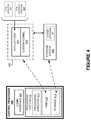
- FIG. 4is a block diagram illustrating control processor 400 .
- Control processor 400illustrates an example of any of the control modules or processors discussed herein, such as processor 211 of FIGS. 2 and 3 .
- control processor 400can be illustrative of any processing system a connectivity card discussed herein.
- Control processor 400includes communication interface 401 and processing system 410 .
- Processing system 410includes processing circuitry 411 , random access memory (RAM) 412 , and storage 413 , although further elements can be included.
- RAMrandom access memory
- Example contents of RAM 412are further detailed in RAM space 420
- example contents of storage 413are further detailed in storage system 460 .
- Processing circuitry 411can be implemented within a single processing device but can also be distributed across multiple processing devices or sub-systems that cooperate in executing program instructions. Examples of processing circuitry 411 include general purpose central processing units, microprocessors, application specific processors, and logic devices, as well as any other type of processing device. In some examples, processing circuitry 411 includes physically distributed processing devices, such as cloud computing systems.
- Communication interface 401includes one or more communication and network interfaces for communicating over communication links, networks, such as packet networks, the Internet, and the like.
- the communication interfacescan include PCIe interfaces, serial links, such as SPI links, I2C links, USB links, UART links, or one or more local or wide area network communication interfaces which can communicate over Ethernet or Internet protocol (IP) links.
- Communication interface 401can include network interfaces configured to communicate using one or more network addresses, which can be associated with different network links. Examples of communication interface 401 include network interface card equipment, transceivers, modems, and other communication circuitry.
- RAM 412 and storage 413 togethercan comprise a non-transitory data storage system, although variations are possible.
- RAM 412 and storage 413can each comprise any storage media readable by processing circuitry 411 and capable of storing software.
- RAM 412can include volatile and nonvolatile, removable and non-removable media implemented in any method or technology for storage of information, such as computer readable instructions, data structures, program modules, or other data.
- Storage 413can include nonvolatile storage media, such as solid-state storage media, flash memory, phase change memory, or magnetic memory, including combinations thereof.
- RAM 412 and storage 413can each be implemented as a single storage device but can also be implemented across multiple storage devices or sub-systems.
- RAM 412 and storage 413can each comprise additional elements, such as controllers, capable of communicating with processing circuitry 311 .
- Software stored on or in RAM 412 or storage 413can comprise computer program instructions, firmware, or some other form of machine-readable processing instructions having processes that when executed a processing system direct control processor 400 to operate as described herein.
- softwarecan drive processor 400 to monitor operating statistics and status for various PCIe traffic and other modules, monitor for connectivity issues that arise with regard to the plurality of PCIe connectors, and responsively mitigate the connectivity issues by at least reconfiguring a communication pathway in the PCIe switch circuit for at least a portion of the PCIe traffic affected by the connectivity issues, among other operations.
- the softwarecan also include user software applications, application programming interfaces (APIs), or user interfaces.
- the softwarecan be implemented as a single application or as multiple applications. In general, the software can, when loaded into a processing system and executed, transform the processing system from a general-purpose device into a special-purpose device customized as described herein.
- RAM space 420illustrates a detailed view of an example configuration of RAM 412 .
- applications 421 and custom kernel 422can reside in flash memory and run in an execute in place (XIP) configuration. This enables quick boots while providing sufficient memory to execute telemetry and PCIe monitoring functions.
- Software applications 423 - 424each comprise executable instructions which can be executed by processor 400 for operating a connectivity card or other circuitry according to the operations discussed herein.
- PCIe monitor 423monitors for connectivity issues that arise with regard to the plurality of PCIe connectors.
- PCIe redirect control 424mitigates connectivity issues by at least reconfiguring a communication pathway in the PCIe switch circuit for at least a portion of the PCIe traffic affected by the connectivity issues.
- Applications 421 and custom kernel 422can reside in RAM space 420 during execution and operation of control processor 400 , and can reside in storage system 460 during a powered-off state, among other locations and states. Applications 421 and custom kernel 422 can be loaded into RAM space 420 during a startup or boot procedure as described for computer operating systems and applications.
- Storage system 460illustrates a detailed view of an example configuration of storage 413 .
- Storage system 460can comprise flash memory such as NAND flash or NOR flash memory, phase change memory, magnetic memory, among other solid-state storage technologies.
- storage system 460includes system software 461 .
- Control processor 400is generally intended to represent a computing system with which at least software 461 and 421 - 424 are deployed and executed in order to render or otherwise implement the operations described herein. However, control processor 400 can also represent any computing system on which at least software 461 and 421 - 424 can be staged and from where software 461 and 421 - 424 can be distributed, transported, downloaded, or otherwise provided to yet another computing system for deployment and execution, or yet additional distribution.
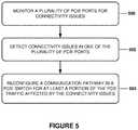
- FIG. 5is a flow diagram illustrating a method of operating a connectivity card. Operations of FIG. 5 can be performed by any of processor 211 , PCIe switch 212 , or control processor 400 , including combinations thereof. Processor 211 will be discussed below as an exemplary processing system.
- control processor 400monitors ports 213 and connector 214 for connectivity issues, (operation 500 ). Control processor 400 then detects connectivity issues among any of ports 213 and connector 214 , (operation 502 ). These connectivity issues can include cable connectivity, such as when an associated cable connected to ports 213 is disconnected or re-connected. The connectivity issues can include failed internal links, such as when traces or portions of the links or ports internal to card 210 fail or are intermittent. Normally, a connectivity issue—such as connectivity loss—would cause a cascading failure problem for the host, referred to as a host panic condition.
- Control processor 400can prevent host panic conditions by isolating the connectivity issue to within PCIe switch circuit 212 , and control processor 400 instructs PCIe switch circuit 212 to redirect the affected PCIe traffic to a redundant link, by reconfiguring a communication pathway within PCIe switch circuit 212 , (operation 504 ).
- expansion card 210is coupled to two separate rackmount PCIe switches 320 - 321 . If a connectivity issue arises with a cable or other portion associated with a first PCIe link between card 210 and switch 320 , then processor 211 can detect this connectivity issue and redirect traffic that was formerly carried over the failed link. This redirection can occur within PCIe switch circuit 212 to redirect the traffic to another link to switch 320 , or to another switch 321 . The nature of the failure might preclude failure redirection to another link on the same switch 320 . In this manner, connectivity failures—such as failed cables, links, or inadvertent cable disconnection, can be isolated from a host system by processor 211 and PCIe switch circuit 212 . Processor 211 or control processor 400 can responsively mitigate PCIe connectivity issues by at least reconfiguring a communication pathway in PCIe switch circuit 212 for at least a portion of the PCIe traffic affected by the connectivity issues.
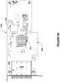
- FIG. 6Ais an oblique view and FIG. 6B is a front view illustrating a connectivity expansion card 600 .
- connectivity expansion card 600comprises control processor (or control circuitry) 610 , PCIe switch circuit 620 , PCIe connectors 630 , and host connector 640 .
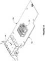
- FIG. 7Ais an oblique view and FIG. 7B is a front view illustrating a connectivity expansion card 700 .
- connectivity expansion card 700comprises control processor (or control circuitry) integrated with PCIe switch circuit 710 , PCIe connectors 720 , and host connector 730 .
Landscapes
- Engineering & Computer Science (AREA)
- Theoretical Computer Science (AREA)
- Physics & Mathematics (AREA)
- General Engineering & Computer Science (AREA)
- General Physics & Mathematics (AREA)
- Mathematical Physics (AREA)
- Computer Hardware Design (AREA)
- Information Transfer Systems (AREA)
Abstract
Description
Claims (20)
Priority Applications (1)
| Application Number | Priority Date | Filing Date | Title |
|---|---|---|---|
| US15/964,263US10614022B2 (en) | 2017-04-27 | 2018-04-27 | PCIe fabric connectivity expansion card |
Applications Claiming Priority (2)
| Application Number | Priority Date | Filing Date | Title |
|---|---|---|---|
| US201762491006P | 2017-04-27 | 2017-04-27 | |
| US15/964,263US10614022B2 (en) | 2017-04-27 | 2018-04-27 | PCIe fabric connectivity expansion card |
Publications (2)
| Publication Number | Publication Date |
|---|---|
| US20180314667A1 US20180314667A1 (en) | 2018-11-01 |
| US10614022B2true US10614022B2 (en) | 2020-04-07 |
Family
ID=63916720
Family Applications (1)
| Application Number | Title | Priority Date | Filing Date |
|---|---|---|---|
| US15/964,263ActiveUS10614022B2 (en) | 2017-04-27 | 2018-04-27 | PCIe fabric connectivity expansion card |
Country Status (3)
| Country | Link |
|---|---|
| US (1) | US10614022B2 (en) |
| TW (1) | TWI669612B (en) |
| WO (1) | WO2018200761A1 (en) |
Cited By (1)
| Publication number | Priority date | Publication date | Assignee | Title |
|---|---|---|---|---|
| US20240385662A1 (en)* | 2021-09-30 | 2024-11-21 | Hangzhou AliCloud Feitian Information Technology Co., Ltd. | Expansion module, pcie expansion module, chassis assembly, computer, and server cluster |
Families Citing this family (8)
| Publication number | Priority date | Publication date | Assignee | Title |
|---|---|---|---|---|
| US10930411B2 (en)* | 2018-10-11 | 2021-02-23 | International Business Machines Corporation | Hybrid cable assembly having shielded and unshielded portions |
| CN109508312B (en)* | 2018-11-14 | 2021-10-29 | 郑州云海信息技术有限公司 | A method and related device for sending hot-adding information of a PCIE external card |
| US11520727B2 (en)* | 2020-11-19 | 2022-12-06 | Qualcomm Incorporated | Sideband signaling in a peripheral component interconnect (PCI) express (PCIE) link |
| US11907149B2 (en)* | 2020-12-09 | 2024-02-20 | Qualcomm Incorporated | Sideband signaling in universal serial bus (USB) type-C communication links |
| US11502433B2 (en)* | 2021-02-10 | 2022-11-15 | Super Micro Computer, Inc. | Circuit card with onboard non-volatile memory for providing cable assembly data to network interface controller chips |
| US11531629B2 (en)* | 2021-03-04 | 2022-12-20 | Liqid Inc. | High density peripheral card chassis |
| US11573917B2 (en) | 2021-03-04 | 2023-02-07 | Liqid Inc. | Low latency computing architecture |
| CN115658578A (en)* | 2022-11-03 | 2023-01-31 | 北京晟芯网络科技有限公司 | A method for realizing protection switching, computer storage medium and terminal |
Citations (67)
| Publication number | Priority date | Publication date | Assignee | Title |
|---|---|---|---|---|
| US5828207A (en) | 1993-04-20 | 1998-10-27 | The United States Of America As Represented By The Secretary Of The Navy | Hold-up circuit with safety discharge for preventing shut-down by momentary power interruption |
| US6061750A (en) | 1998-02-20 | 2000-05-09 | International Business Machines Corporation | Failover system for a DASD storage controller reconfiguring a first processor, a bridge, a second host adaptor, and a second device adaptor upon a second processor failure |
| US6325636B1 (en) | 2000-07-20 | 2001-12-04 | Rlx Technologies, Inc. | Passive midplane for coupling web server processing cards with a network interface(s) |
| US20020059428A1 (en) | 1998-11-10 | 2002-05-16 | Netscaler, Inc. | Internet client-server multiplexer |
| US20030110423A1 (en) | 2001-12-11 | 2003-06-12 | Advanced Micro Devices, Inc. | Variable maximum die temperature based on performance state |
| US20030126478A1 (en) | 2001-12-28 | 2003-07-03 | Burns James S. | Multiple mode power throttle mechanism |
| US20050223136A1 (en) | 2003-03-05 | 2005-10-06 | Fujitsu Limited | System and method for controlling DMA data transfer |
| US20060277206A1 (en) | 2005-06-02 | 2006-12-07 | Bailey Philip G | Automated reporting of computer system metrics |
| US20070067432A1 (en) | 2005-09-21 | 2007-03-22 | Toshiaki Tarui | Computer system and I/O bridge |
| US7243145B1 (en) | 2002-09-30 | 2007-07-10 | Electronic Data Systems Corporation | Generation of computer resource utilization data per computer application |
| US7260487B2 (en) | 2005-11-29 | 2007-08-21 | International Business Machines Corporation | Histogram difference method and system for power/performance measurement and management |
| US20080034153A1 (en) | 1999-08-04 | 2008-02-07 | Super Talent Electronics Inc. | Flash Module with Plane-Interleaved Sequential Writes to Restricted-Write Flash Chips |
| US20080198744A1 (en) | 2002-08-14 | 2008-08-21 | Siemens Aktiengesellschaft | Access control for packet-oriented networks |
| US20080281938A1 (en) | 2007-05-09 | 2008-11-13 | Oracle International Corporation | Selecting a master node in a multi-node computer system |
| US20090006837A1 (en) | 2007-06-29 | 2009-01-01 | Rothman Michael A | Method and apparatus for improved memory reliability, availability and serviceability |
| US7505889B2 (en) | 2002-02-25 | 2009-03-17 | Zoran Corporation | Transcoding media system |
| US20090100280A1 (en) | 2007-10-11 | 2009-04-16 | Lindsay Steven B | Method and system for improving pci-e l1 aspm exit latency |
| US20090193201A1 (en) | 2008-01-24 | 2009-07-30 | Brittain Mark A | System to Increase the Overall Bandwidth of a Memory Channel By Allowing the Memory Channel to Operate at a Frequency Independent from a Memory Device Frequency |
| US20090190427A1 (en) | 2008-01-24 | 2009-07-30 | Brittain Mark A | System to Enable a Memory Hub Device to Manage Thermal Conditions at a Memory Device Level Transparent to a Memory Controller |
| US20090193203A1 (en) | 2008-01-24 | 2009-07-30 | Brittain Mark A | System to Reduce Latency by Running a Memory Channel Frequency Fully Asynchronous from a Memory Device Frequency |
| US7606960B2 (en) | 2004-03-26 | 2009-10-20 | Intel Corporation | Apparatus for adjusting a clock frequency of a variable speed bus |
| US20090276551A1 (en) | 2008-05-05 | 2009-11-05 | International Business Machines Corporation | Native and Non-Native I/O Virtualization in a Single Adapter |
| US20100088467A1 (en) | 2008-10-02 | 2010-04-08 | Jae Don Lee | Memory device and operating method of memory device |
| US7725757B2 (en) | 2004-03-03 | 2010-05-25 | Intel Corporation | Method and system for fast frequency switch for a power throttle in an integrated device |
| US7877542B2 (en) | 2000-01-06 | 2011-01-25 | Super Talent Electronics, Inc. | High integration of intelligent non-volatile memory device |
| US20110289510A1 (en) | 2009-02-17 | 2011-11-24 | Rambus Inc. | Atomic-operation coalescing technique in multi-chip systems |
| US20110299317A1 (en) | 2006-11-29 | 2011-12-08 | Shaeffer Ian P | Integrated circuit heating to effect in-situ annealing |
| US20110320861A1 (en) | 2010-06-23 | 2011-12-29 | International Business Machines Corporation | Switch failover control in a multiprocessor computer system |
| US20120030544A1 (en) | 2010-07-27 | 2012-02-02 | Fisher-Jeffes Timothy Perrin | Accessing Memory for Data Decoding |
| US8125919B1 (en) | 2009-03-24 | 2012-02-28 | Sprint Spectrum L.P. | Method and system for selectively releasing network resources |
| US8150800B2 (en) | 2007-03-28 | 2012-04-03 | Netapp, Inc. | Advanced clock synchronization technique |
| US20120089854A1 (en) | 2010-10-10 | 2012-04-12 | pureSilicon Inc. | Systems and methods for optimizing data storage among a plurality of solid state memory subsystems |
| US20120151118A1 (en) | 2010-12-13 | 2012-06-14 | Fusion-Io, Inc. | Apparatus, system, and method for auto-commit memory |
| US20120166699A1 (en) | 2010-12-22 | 2012-06-28 | Panakaj Kumar | Method and apparatus to provide a high availability solid state drive |
| US20120210163A1 (en) | 2011-02-11 | 2012-08-16 | Byungcheol Cho | Alarm-based backup and restoration for a semiconductor storage device |
| US20120317433A1 (en) | 2011-06-13 | 2012-12-13 | SMART Storage Systems, Inc. | Data storage system with power cycle management and method of operation thereof |
| US20130132643A1 (en) | 2011-11-17 | 2013-05-23 | Futurewei Technologies, Inc. | Method and Apparatus for Scalable Low Latency Solid State Drive Interface |
| US20130185416A1 (en) | 2011-07-11 | 2013-07-18 | Metaswitch Networks Ltd. | Controlling an Apparatus |
| US20140047166A1 (en) | 2012-08-08 | 2014-02-13 | Avalanche Technology, Inc. | Storage system employing mram and array of solid state disks with integrated switch |
| US8656117B1 (en) | 2008-10-30 | 2014-02-18 | Nvidia Corporation | Read completion data management |
| US20140059265A1 (en) | 2012-08-23 | 2014-02-27 | Dell Products, Lp | Fabric Independent PCIe Cluster Manager |
| US20140056319A1 (en) | 2012-08-21 | 2014-02-27 | Emerson Network Power - Embedded Computing, Inc. | High Precision Timer in CPU Cluster |
| US20140075235A1 (en) | 2012-09-07 | 2014-03-13 | Sundeep Chandhoke | Switch for Clock Synchronization Over A Switched Fabric |
| US20140103955A1 (en) | 2012-10-11 | 2014-04-17 | Hamilton Sundstrand Corporation | System and method for automated failure detection of hold-up power storage devices |
| US20140108846A1 (en) | 2012-10-15 | 2014-04-17 | Dell Products L.P. | Supplemental power system for power excursions |
| US8756360B1 (en) | 2011-09-26 | 2014-06-17 | Agilent Technologies, Inc. | PCI-E compatible chassis having multi-host capability |
| US8880771B2 (en) | 2012-10-25 | 2014-11-04 | Plx Technology, Inc. | Method and apparatus for securing and segregating host to host messaging on PCIe fabric |
| TW201445317A (en) | 2013-02-28 | 2014-12-01 | Intel Corp | Leveraging an enumeration and/or configuration mechanism of one interconnect protocol for a different interconnect protocol |
| US20140353264A1 (en) | 2013-05-30 | 2014-12-04 | Hewlett-Packard Development Company, L.P. | Modules to contain interface cards |
| US20140365714A1 (en) | 2013-06-07 | 2014-12-11 | Sanmina Corporation | PERIPHERAL COMPONENT INTERCONNECT EXPRESS (PCIe) SOLID STATE DRIVE (SSD) ACCELERATOR |
| US20150074322A1 (en) | 2013-09-06 | 2015-03-12 | Cisco Technology, Inc. | Universal pci express port |
| US20150121115A1 (en) | 2011-12-27 | 2015-04-30 | Intel Corporation | Multi-protocol i/o interconnect time synchronization |
| US20150186437A1 (en) | 2013-03-15 | 2015-07-02 | Datadirect Networks, Inc. | Data storage system having mutable objects incorporating time |
| US20150212755A1 (en) | 2014-01-30 | 2015-07-30 | Avalanche Technology, Inc. | Method of managing throughput of redundant array of independent disks (raid) groups in a solid state disk array |
| US20150261710A1 (en) | 2014-03-14 | 2015-09-17 | Emilio Billi | Low-profile half length pci express form factor embedded pci express multi ports switch and related accessories |
| US20150304423A1 (en) | 2014-04-21 | 2015-10-22 | Hitachi, Ltd. | Computer system |
| US20150309951A1 (en) | 2014-04-25 | 2015-10-29 | Liqid Inc. | Power handling in a scalable storage system |
| US20150347345A1 (en)* | 2014-04-30 | 2015-12-03 | Cirrascale Corporation | Gen3 pci-express riser |
| US20150373115A1 (en)* | 2014-06-23 | 2015-12-24 | Liqid Inc. | Modular switched fabric for data storage systems |
| US20160072640A1 (en) | 2012-03-29 | 2016-03-10 | Telefonaktiebolaget L M Ericsson (Publ) | Mac copy in nodes detecting failure in a ring protection communication network |
| US20160070661A1 (en) | 2014-09-08 | 2016-03-10 | Quanta Computer Inc. | Flexible PCIe Routing |
| US20160147628A1 (en) | 2014-11-21 | 2016-05-26 | International Business Machines Corporation | Detecting and sparing of optical pcie cable channel attached io drawer |
| US20160197996A1 (en) | 2011-03-08 | 2016-07-07 | Rackspace Us, Inc. | Massively scalable object storage system |
| US20160248631A1 (en) | 2007-04-23 | 2016-08-25 | David D. Duchesneau | Computing infrastructure |
| US9552316B2 (en) | 2014-03-29 | 2017-01-24 | Intel Corporation | Techniques for adaptive interface support |
| US9602437B1 (en) | 2012-10-03 | 2017-03-21 | Tracey M. Bernath | System and method for accelerating network applications using an enhanced network interface and massively parallel distributed processing |
| US20180101500A1 (en)* | 2016-10-07 | 2018-04-12 | Liqid Inc. | Modular Carrier Form Factors For Computing Platforms |
- 2018
- 2018-04-26WOPCT/US2018/029496patent/WO2018200761A1/ennot_activeCeased
- 2018-04-27TWTW107114399Apatent/TWI669612B/enactive
- 2018-04-27USUS15/964,263patent/US10614022B2/enactiveActive
Patent Citations (68)
| Publication number | Priority date | Publication date | Assignee | Title |
|---|---|---|---|---|
| US5828207A (en) | 1993-04-20 | 1998-10-27 | The United States Of America As Represented By The Secretary Of The Navy | Hold-up circuit with safety discharge for preventing shut-down by momentary power interruption |
| US6061750A (en) | 1998-02-20 | 2000-05-09 | International Business Machines Corporation | Failover system for a DASD storage controller reconfiguring a first processor, a bridge, a second host adaptor, and a second device adaptor upon a second processor failure |
| US20020059428A1 (en) | 1998-11-10 | 2002-05-16 | Netscaler, Inc. | Internet client-server multiplexer |
| US20080034153A1 (en) | 1999-08-04 | 2008-02-07 | Super Talent Electronics Inc. | Flash Module with Plane-Interleaved Sequential Writes to Restricted-Write Flash Chips |
| US7877542B2 (en) | 2000-01-06 | 2011-01-25 | Super Talent Electronics, Inc. | High integration of intelligent non-volatile memory device |
| US6325636B1 (en) | 2000-07-20 | 2001-12-04 | Rlx Technologies, Inc. | Passive midplane for coupling web server processing cards with a network interface(s) |
| US20030110423A1 (en) | 2001-12-11 | 2003-06-12 | Advanced Micro Devices, Inc. | Variable maximum die temperature based on performance state |
| US20030126478A1 (en) | 2001-12-28 | 2003-07-03 | Burns James S. | Multiple mode power throttle mechanism |
| US7505889B2 (en) | 2002-02-25 | 2009-03-17 | Zoran Corporation | Transcoding media system |
| US20080198744A1 (en) | 2002-08-14 | 2008-08-21 | Siemens Aktiengesellschaft | Access control for packet-oriented networks |
| US7243145B1 (en) | 2002-09-30 | 2007-07-10 | Electronic Data Systems Corporation | Generation of computer resource utilization data per computer application |
| US20050223136A1 (en) | 2003-03-05 | 2005-10-06 | Fujitsu Limited | System and method for controlling DMA data transfer |
| US7725757B2 (en) | 2004-03-03 | 2010-05-25 | Intel Corporation | Method and system for fast frequency switch for a power throttle in an integrated device |
| US7606960B2 (en) | 2004-03-26 | 2009-10-20 | Intel Corporation | Apparatus for adjusting a clock frequency of a variable speed bus |
| US20060277206A1 (en) | 2005-06-02 | 2006-12-07 | Bailey Philip G | Automated reporting of computer system metrics |
| US20070067432A1 (en) | 2005-09-21 | 2007-03-22 | Toshiaki Tarui | Computer system and I/O bridge |
| US7260487B2 (en) | 2005-11-29 | 2007-08-21 | International Business Machines Corporation | Histogram difference method and system for power/performance measurement and management |
| US20110299317A1 (en) | 2006-11-29 | 2011-12-08 | Shaeffer Ian P | Integrated circuit heating to effect in-situ annealing |
| US8150800B2 (en) | 2007-03-28 | 2012-04-03 | Netapp, Inc. | Advanced clock synchronization technique |
| US20160248631A1 (en) | 2007-04-23 | 2016-08-25 | David D. Duchesneau | Computing infrastructure |
| US20080281938A1 (en) | 2007-05-09 | 2008-11-13 | Oracle International Corporation | Selecting a master node in a multi-node computer system |
| US20090006837A1 (en) | 2007-06-29 | 2009-01-01 | Rothman Michael A | Method and apparatus for improved memory reliability, availability and serviceability |
| US20090100280A1 (en) | 2007-10-11 | 2009-04-16 | Lindsay Steven B | Method and system for improving pci-e l1 aspm exit latency |
| US20090190427A1 (en) | 2008-01-24 | 2009-07-30 | Brittain Mark A | System to Enable a Memory Hub Device to Manage Thermal Conditions at a Memory Device Level Transparent to a Memory Controller |
| US20090193201A1 (en) | 2008-01-24 | 2009-07-30 | Brittain Mark A | System to Increase the Overall Bandwidth of a Memory Channel By Allowing the Memory Channel to Operate at a Frequency Independent from a Memory Device Frequency |
| US20090193203A1 (en) | 2008-01-24 | 2009-07-30 | Brittain Mark A | System to Reduce Latency by Running a Memory Channel Frequency Fully Asynchronous from a Memory Device Frequency |
| US20090276551A1 (en) | 2008-05-05 | 2009-11-05 | International Business Machines Corporation | Native and Non-Native I/O Virtualization in a Single Adapter |
| US20100088467A1 (en) | 2008-10-02 | 2010-04-08 | Jae Don Lee | Memory device and operating method of memory device |
| US8656117B1 (en) | 2008-10-30 | 2014-02-18 | Nvidia Corporation | Read completion data management |
| US20110289510A1 (en) | 2009-02-17 | 2011-11-24 | Rambus Inc. | Atomic-operation coalescing technique in multi-chip systems |
| US8125919B1 (en) | 2009-03-24 | 2012-02-28 | Sprint Spectrum L.P. | Method and system for selectively releasing network resources |
| US20110320861A1 (en) | 2010-06-23 | 2011-12-29 | International Business Machines Corporation | Switch failover control in a multiprocessor computer system |
| US20120030544A1 (en) | 2010-07-27 | 2012-02-02 | Fisher-Jeffes Timothy Perrin | Accessing Memory for Data Decoding |
| US20120089854A1 (en) | 2010-10-10 | 2012-04-12 | pureSilicon Inc. | Systems and methods for optimizing data storage among a plurality of solid state memory subsystems |
| US8688926B2 (en) | 2010-10-10 | 2014-04-01 | Liqid Inc. | Systems and methods for optimizing data storage among a plurality of solid state memory subsystems |
| US20120151118A1 (en) | 2010-12-13 | 2012-06-14 | Fusion-Io, Inc. | Apparatus, system, and method for auto-commit memory |
| US20120166699A1 (en) | 2010-12-22 | 2012-06-28 | Panakaj Kumar | Method and apparatus to provide a high availability solid state drive |
| US20120210163A1 (en) | 2011-02-11 | 2012-08-16 | Byungcheol Cho | Alarm-based backup and restoration for a semiconductor storage device |
| US20160197996A1 (en) | 2011-03-08 | 2016-07-07 | Rackspace Us, Inc. | Massively scalable object storage system |
| US20120317433A1 (en) | 2011-06-13 | 2012-12-13 | SMART Storage Systems, Inc. | Data storage system with power cycle management and method of operation thereof |
| US20130185416A1 (en) | 2011-07-11 | 2013-07-18 | Metaswitch Networks Ltd. | Controlling an Apparatus |
| US8756360B1 (en) | 2011-09-26 | 2014-06-17 | Agilent Technologies, Inc. | PCI-E compatible chassis having multi-host capability |
| US20130132643A1 (en) | 2011-11-17 | 2013-05-23 | Futurewei Technologies, Inc. | Method and Apparatus for Scalable Low Latency Solid State Drive Interface |
| US20150121115A1 (en) | 2011-12-27 | 2015-04-30 | Intel Corporation | Multi-protocol i/o interconnect time synchronization |
| US20160072640A1 (en) | 2012-03-29 | 2016-03-10 | Telefonaktiebolaget L M Ericsson (Publ) | Mac copy in nodes detecting failure in a ring protection communication network |
| US20140047166A1 (en) | 2012-08-08 | 2014-02-13 | Avalanche Technology, Inc. | Storage system employing mram and array of solid state disks with integrated switch |
| US20140056319A1 (en) | 2012-08-21 | 2014-02-27 | Emerson Network Power - Embedded Computing, Inc. | High Precision Timer in CPU Cluster |
| US20140059265A1 (en) | 2012-08-23 | 2014-02-27 | Dell Products, Lp | Fabric Independent PCIe Cluster Manager |
| US20140075235A1 (en) | 2012-09-07 | 2014-03-13 | Sundeep Chandhoke | Switch for Clock Synchronization Over A Switched Fabric |
| US9602437B1 (en) | 2012-10-03 | 2017-03-21 | Tracey M. Bernath | System and method for accelerating network applications using an enhanced network interface and massively parallel distributed processing |
| US20140103955A1 (en) | 2012-10-11 | 2014-04-17 | Hamilton Sundstrand Corporation | System and method for automated failure detection of hold-up power storage devices |
| US20140108846A1 (en) | 2012-10-15 | 2014-04-17 | Dell Products L.P. | Supplemental power system for power excursions |
| US8880771B2 (en) | 2012-10-25 | 2014-11-04 | Plx Technology, Inc. | Method and apparatus for securing and segregating host to host messaging on PCIe fabric |
| TW201445317A (en) | 2013-02-28 | 2014-12-01 | Intel Corp | Leveraging an enumeration and/or configuration mechanism of one interconnect protocol for a different interconnect protocol |
| US20150186437A1 (en) | 2013-03-15 | 2015-07-02 | Datadirect Networks, Inc. | Data storage system having mutable objects incorporating time |
| US20140353264A1 (en) | 2013-05-30 | 2014-12-04 | Hewlett-Packard Development Company, L.P. | Modules to contain interface cards |
| US20140365714A1 (en) | 2013-06-07 | 2014-12-11 | Sanmina Corporation | PERIPHERAL COMPONENT INTERCONNECT EXPRESS (PCIe) SOLID STATE DRIVE (SSD) ACCELERATOR |
| US20150074322A1 (en) | 2013-09-06 | 2015-03-12 | Cisco Technology, Inc. | Universal pci express port |
| US20150212755A1 (en) | 2014-01-30 | 2015-07-30 | Avalanche Technology, Inc. | Method of managing throughput of redundant array of independent disks (raid) groups in a solid state disk array |
| US20150261710A1 (en) | 2014-03-14 | 2015-09-17 | Emilio Billi | Low-profile half length pci express form factor embedded pci express multi ports switch and related accessories |
| US9552316B2 (en) | 2014-03-29 | 2017-01-24 | Intel Corporation | Techniques for adaptive interface support |
| US20150304423A1 (en) | 2014-04-21 | 2015-10-22 | Hitachi, Ltd. | Computer system |
| US20150309951A1 (en) | 2014-04-25 | 2015-10-29 | Liqid Inc. | Power handling in a scalable storage system |
| US20150347345A1 (en)* | 2014-04-30 | 2015-12-03 | Cirrascale Corporation | Gen3 pci-express riser |
| US20150373115A1 (en)* | 2014-06-23 | 2015-12-24 | Liqid Inc. | Modular switched fabric for data storage systems |
| US20160070661A1 (en) | 2014-09-08 | 2016-03-10 | Quanta Computer Inc. | Flexible PCIe Routing |
| US20160147628A1 (en) | 2014-11-21 | 2016-05-26 | International Business Machines Corporation | Detecting and sparing of optical pcie cable channel attached io drawer |
| US20180101500A1 (en)* | 2016-10-07 | 2018-04-12 | Liqid Inc. | Modular Carrier Form Factors For Computing Platforms |
Non-Patent Citations (6)
| Title |
|---|
| Aragon, Juan L. et al., "Control Speculation for Energy-Efficient Next-Generation Superscalar Processors," IEEE Transactions on Computers, vol. 55, No. 3, pp. 281-291, Mar. 2006. |
| International Application No. PCT/US2017/046602, International Search Report & Written Opinion, 8 pages, dated Oct. 19, 2017. |
| International Application No. PCT/US2017/046607, International Search Report & Written Opinion, 7 pages, dated Oct. 23, 2017. |
| International Application No. PCT/US2018/029496, International Search Report & Written Opinion, 10 pages, dated Jul. 10, 2018. |
| Lu, Yingping et al., "Performance Study of iSCSI-Based Storage Subsystems," IEEE Communications Magazine, pp. 76-82, Aug. 2003. |
| Taiwanese Patent Application No. 107114399, Office Action, 14 pages, dated Jan. 18, 2019. |
Cited By (1)
| Publication number | Priority date | Publication date | Assignee | Title |
|---|---|---|---|---|
| US20240385662A1 (en)* | 2021-09-30 | 2024-11-21 | Hangzhou AliCloud Feitian Information Technology Co., Ltd. | Expansion module, pcie expansion module, chassis assembly, computer, and server cluster |
Also Published As
| Publication number | Publication date |
|---|---|
| TWI669612B (en) | 2019-08-21 |
| US20180314667A1 (en) | 2018-11-01 |
| TW201842449A (en) | 2018-12-01 |
| WO2018200761A1 (en) | 2018-11-01 |
Similar Documents
| Publication | Publication Date | Title |
|---|---|---|
| US10614022B2 (en) | PCIe fabric connectivity expansion card | |
| US12321296B2 (en) | Multi-protocol IO infrastructure for a flexible storage platform | |
| US10866923B2 (en) | Storage control interposers in data storage systems | |
| US10754742B2 (en) | Network failover handling in computing systems | |
| EP3158455B1 (en) | Modular switched fabric for data storage systems | |
| US10993345B2 (en) | Peripheral storage card with offset slot alignment | |
| US9697167B2 (en) | Implementing health check for optical cable attached PCIE enclosure | |
| US20150286601A1 (en) | Implementing sideband control structure for pcie cable cards and io expansion enclosures | |
| US10846159B2 (en) | System and method for managing, resetting and diagnosing failures of a device management bus | |
| US10853213B2 (en) | Validation of installation of removeable computer hardware components | |
| US8352661B1 (en) | Data storage systems having seamless software upgrades | |
| HK40001549B (en) | Multi-port interposer architectures in data storage systems |
Legal Events
| Date | Code | Title | Description |
|---|---|---|---|
| FEPP | Fee payment procedure | Free format text:ENTITY STATUS SET TO UNDISCOUNTED (ORIGINAL EVENT CODE: BIG.); ENTITY STATUS OF PATENT OWNER: SMALL ENTITY | |
| FEPP | Fee payment procedure | Free format text:ENTITY STATUS SET TO SMALL (ORIGINAL EVENT CODE: SMAL); ENTITY STATUS OF PATENT OWNER: SMALL ENTITY | |
| STPP | Information on status: patent application and granting procedure in general | Free format text:DOCKETED NEW CASE - READY FOR EXAMINATION | |
| AS | Assignment | Owner name:LIQID INC., COLORADO Free format text:ASSIGNMENT OF ASSIGNORS INTEREST;ASSIGNORS:LONG, CHRISTOPHER R.;HEYD, ANDREW RUDOLPH;CANNATA, JAMES SCOTT;AND OTHERS;SIGNING DATES FROM 20180427 TO 20181003;REEL/FRAME:048412/0991 | |
| STPP | Information on status: patent application and granting procedure in general | Free format text:PRE-INTERVIEW COMMUNICATION MAILED | |
| STPP | Information on status: patent application and granting procedure in general | Free format text:RESPONSE TO NON-FINAL OFFICE ACTION ENTERED AND FORWARDED TO EXAMINER | |
| STPP | Information on status: patent application and granting procedure in general | Free format text:NON FINAL ACTION MAILED | |
| AS | Assignment | Owner name:CANADIAN IMPERIAL BANK OF COMMERCE, CANADA Free format text:SECURITY INTEREST;ASSIGNOR:LIQID INC.;REEL/FRAME:050630/0636 Effective date:20191003 | |
| STPP | Information on status: patent application and granting procedure in general | Free format text:RESPONSE TO NON-FINAL OFFICE ACTION ENTERED AND FORWARDED TO EXAMINER | |
| STPP | Information on status: patent application and granting procedure in general | Free format text:NOTICE OF ALLOWANCE MAILED -- APPLICATION RECEIVED IN OFFICE OF PUBLICATIONS | |
| STPP | Information on status: patent application and granting procedure in general | Free format text:NOTICE OF ALLOWANCE MAILED -- APPLICATION RECEIVED IN OFFICE OF PUBLICATIONS | |
| STCF | Information on status: patent grant | Free format text:PATENTED CASE | |
| AS | Assignment | Owner name:HORIZON TECHNOLOGY FINANCE CORPORATION, CONNECTICUT Free format text:SECURITY INTEREST;ASSIGNOR:LIQID INC.;REEL/FRAME:054900/0539 Effective date:20201231 | |
| AS | Assignment | Owner name:LIQID INC., COLORADO Free format text:RELEASE BY SECURED PARTY;ASSIGNOR:CANADIAN IMPERIAL BANK OF COMMERCE;REEL/FRAME:055953/0860 Effective date:20210406 | |
| MAFP | Maintenance fee payment | Free format text:PAYMENT OF MAINTENANCE FEE, 4TH YR, SMALL ENTITY (ORIGINAL EVENT CODE: M2551); ENTITY STATUS OF PATENT OWNER: SMALL ENTITY Year of fee payment:4 |