US10614019B2 - Method and system for fast ordered writes with target collaboration - Google Patents
Method and system for fast ordered writes with target collaborationDownload PDFInfo
- Publication number
- US10614019B2 US10614019B2US15/581,707US201715581707AUS10614019B2US 10614019 B2US10614019 B2US 10614019B2US 201715581707 AUS201715581707 AUS 201715581707AUS 10614019 B2US10614019 B2US 10614019B2
- Authority
- US
- United States
- Prior art keywords
- storage module
- commit request
- commit
- storage
- data
- Prior art date
- Legal status (The legal status is an assumption and is not a legal conclusion. Google has not performed a legal analysis and makes no representation as to the accuracy of the status listed.)
- Active
Links
Images


Classifications
- G—PHYSICS
- G06—COMPUTING OR CALCULATING; COUNTING
- G06F—ELECTRIC DIGITAL DATA PROCESSING
- G06F13/00—Interconnection of, or transfer of information or other signals between, memories, input/output devices or central processing units
- G06F13/38—Information transfer, e.g. on bus
- G06F13/40—Bus structure
- G06F13/4063—Device-to-bus coupling
- G06F13/4068—Electrical coupling
- G—PHYSICS
- G06—COMPUTING OR CALCULATING; COUNTING
- G06F—ELECTRIC DIGITAL DATA PROCESSING
- G06F13/00—Interconnection of, or transfer of information or other signals between, memories, input/output devices or central processing units
- G06F13/14—Handling requests for interconnection or transfer
- G06F13/16—Handling requests for interconnection or transfer for access to memory bus
- G06F13/1605—Handling requests for interconnection or transfer for access to memory bus based on arbitration
- G06F13/161—Handling requests for interconnection or transfer for access to memory bus based on arbitration with latency improvement
- G06F13/1626—Handling requests for interconnection or transfer for access to memory bus based on arbitration with latency improvement by reordering requests
- G—PHYSICS
- G06—COMPUTING OR CALCULATING; COUNTING
- G06F—ELECTRIC DIGITAL DATA PROCESSING
- G06F13/00—Interconnection of, or transfer of information or other signals between, memories, input/output devices or central processing units
- G06F13/14—Handling requests for interconnection or transfer
- G06F13/16—Handling requests for interconnection or transfer for access to memory bus
- G06F13/1605—Handling requests for interconnection or transfer for access to memory bus based on arbitration
- G06F13/1642—Handling requests for interconnection or transfer for access to memory bus based on arbitration with request queuing
- G—PHYSICS
- G06—COMPUTING OR CALCULATING; COUNTING
- G06F—ELECTRIC DIGITAL DATA PROCESSING
- G06F13/00—Interconnection of, or transfer of information or other signals between, memories, input/output devices or central processing units
- G06F13/14—Handling requests for interconnection or transfer
- G06F13/16—Handling requests for interconnection or transfer for access to memory bus
- G06F13/1668—Details of memory controller
- G06F13/1673—Details of memory controller using buffers
- G—PHYSICS
- G06—COMPUTING OR CALCULATING; COUNTING
- G06F—ELECTRIC DIGITAL DATA PROCESSING
- G06F13/00—Interconnection of, or transfer of information or other signals between, memories, input/output devices or central processing units
- G06F13/38—Information transfer, e.g. on bus
- G06F13/42—Bus transfer protocol, e.g. handshake; Synchronisation
- G06F13/4282—Bus transfer protocol, e.g. handshake; Synchronisation on a serial bus, e.g. I2C bus, SPI bus
- G—PHYSICS
- G06—COMPUTING OR CALCULATING; COUNTING
- G06F—ELECTRIC DIGITAL DATA PROCESSING
- G06F3/00—Input arrangements for transferring data to be processed into a form capable of being handled by the computer; Output arrangements for transferring data from processing unit to output unit, e.g. interface arrangements
- G06F3/06—Digital input from, or digital output to, record carriers, e.g. RAID, emulated record carriers or networked record carriers
- G06F3/0601—Interfaces specially adapted for storage systems
- G06F3/0602—Interfaces specially adapted for storage systems specifically adapted to achieve a particular effect
- G06F3/0604—Improving or facilitating administration, e.g. storage management
- G—PHYSICS
- G06—COMPUTING OR CALCULATING; COUNTING
- G06F—ELECTRIC DIGITAL DATA PROCESSING
- G06F3/00—Input arrangements for transferring data to be processed into a form capable of being handled by the computer; Output arrangements for transferring data from processing unit to output unit, e.g. interface arrangements
- G06F3/06—Digital input from, or digital output to, record carriers, e.g. RAID, emulated record carriers or networked record carriers
- G06F3/0601—Interfaces specially adapted for storage systems
- G06F3/0628—Interfaces specially adapted for storage systems making use of a particular technique
- G06F3/0655—Vertical data movement, i.e. input-output transfer; data movement between one or more hosts and one or more storage devices
- G06F3/0659—Command handling arrangements, e.g. command buffers, queues, command scheduling
- G—PHYSICS
- G06—COMPUTING OR CALCULATING; COUNTING
- G06F—ELECTRIC DIGITAL DATA PROCESSING
- G06F3/00—Input arrangements for transferring data to be processed into a form capable of being handled by the computer; Output arrangements for transferring data from processing unit to output unit, e.g. interface arrangements
- G06F3/06—Digital input from, or digital output to, record carriers, e.g. RAID, emulated record carriers or networked record carriers
- G06F3/0601—Interfaces specially adapted for storage systems
- G06F3/0668—Interfaces specially adapted for storage systems adopting a particular infrastructure
- G06F3/0671—In-line storage system
- G06F3/0683—Plurality of storage devices
- G—PHYSICS
- G06—COMPUTING OR CALCULATING; COUNTING
- G06F—ELECTRIC DIGITAL DATA PROCESSING
- G06F2213/00—Indexing scheme relating to interconnection of, or transfer of information or other signals between, memories, input/output devices or central processing units
- G06F2213/0026—PCI express
Definitions
- Storage appliancesinclude storage media and provide a mechanism to enable clients to write data to and to read data from the storage media.
- FIGS. 1A-1Cshow systems in accordance with one or more embodiments of the technology.
- FIGS. 2-5show flowcharts in accordance with one or more embodiments of the technology.
- FIG. 6shows an example system in accordance with one or more embodiments of the technology.
- ordinal numberse.g., first, second, third, etc.
- an elementi.e., any noun in the application.
- the use of ordinal numbersis not to imply or create any particular ordering of the elements nor to limit any element to being only a single element unless expressly disclosed, such as by the use of the terms “before”, “after”, “single”, and other such terminology. Rather, the use of ordinal numbers is to distinguish between the elements.
- a first elementis distinct from a second element, and the first element may encompass more than one element and succeed (or precede) the second element in an ordering of elements.
- any component described with regard to a figurein various embodiments of the technology, may be equivalent to one or more like-named components described with regard to any other figure.
- descriptions of these componentswill not be repeated with regard to each figure.
- each and every embodiment of the components of each figureis incorporated by reference and assumed to be optionally present within every other figure having one or more like-named components.
- any description of the components of a figureis to be interpreted as an optional embodiment which may be implemented in addition to, in conjunction with, or in place of the embodiments described with regard to a corresponding like-named component in any other figure.
- embodiments of the technologyrelate to a method and system for performing fast ordered writes in a storage appliance that includes multiple separate storage modules. More specifically, embodiments of the technology enable multicasting of data to multiple storage modules in a storage appliance, where the order in which the write requests are processed is the same across all storage modules in the storage appliance. Embodiments of the technology enable the aforementioned ordering without requiring the clients to coordinate the writing of data to the storage appliance. In particular, embodiments of the technology enforce ordering of write requests using a fabric (e.g., a PCIe fabric) in combination with coordination between the storage modules (see e.g., FIGS. 4-5 ).
- a fabrice.g., a PCIe fabric
- the orderingis consistent across the storage modules such that the data stored in the individual storage modules (or a subset of the storage modules) is the same.
- the storage applianceincludes three storage modules ( 1 , 2 , 3 ).
- client Aissues a first write request (A) specifying an object and offset
- Client Bissues a second write request (B) specifying the same object and offset.
- Embodiments of the technologyensure that the write requests (A, B) are processed in the same order on each of the storage modules such that after both write requests have been processed on the three storage modules ( 1 , 2 , 3 ), the data stored for the specific object and offset is the same on each of the three storage modules ( 1 , 2 , 3 ).
- FIG. 1Ashows a system in accordance with one or more embodiments of the technology.
- the systemincludes one or more clients (client A ( 108 A)-client M ( 108 M)) that are operatively connected to a storage appliance ( 100 ).
- the clients ( 108 A- 108 M)may be any type of physical system that includes functionality to issue a read request to the storage appliance ( 100 ) and/or to issue a write request to the storage appliance ( 100 ). Though not shown in FIG. 1A , each of the clients ( 108 A- 108 M) may include a client processor (not shown), client memory (not shown), and any other software and/or hardware necessary to implement one or more embodiments of the technology.
- the clients ( 108 A- 108 M)are configured to execute an operating system (OS) that includes a file system.
- the file systemprovides a mechanism for the storage and retrieval of files from the storage appliance ( 100 ). More specifically, the file system includes functionality to perform the necessary actions to issue read requests and write requests to the storage appliance ( 100 ).
- the file systemmay also provide programming interfaces to enable the creation and deletion of files, reading and writing of files, performing seeks within a file, creating and deleting directories, managing directory contents, etc.
- the file systemalso provides management interfaces to create and delete file systems.
- the operating systemvia the file system typically provides file manipulation interfaces to open, close, read, and write the data within each file and/or to manipulate the corresponding metadata.
- the clientis configured to execute a block driver that is used to access the storage appliance.
- the clientis configured to execute an application programming interface (API) that enables the client to access the storage appliance.
- APIapplication programming interface
- the clients ( 108 A- 108 M)interface with the fabric ( 106 ) of the storage appliance ( 100 ) to communicate with the storage appliance ( 100 ), as further described below in FIG. 2 .
- the storage appliance ( 100 )is a system that includes persistent storage, and is configured to service read requests and/or write requests from one or more clients ( 108 A- 108 M).
- a fabric106
- the storage arraymay enable a modular configuration of the storage appliance, where storage modules may be added to or removed from the storage appliance ( 100 ), as needed or desired.
- the storage applianceincludes the fabric ( 106 ).
- the fabric ( 106 )may provide physical connectivity between the clients ( 108 A- 108 M) and the storage module(s) ( 104 A- 104 N) using one or more of the following protocols: Peripheral Component Interconnect (PCI), PCI-Express (PCIe), PCI-eXtended (PCI-X), Non-Volatile Memory Express (NVMe), Non-Volatile Memory Express (NVMe) over a PCI-Express fabric, Non-Volatile Memory Express (NVMe) over an Ethernet fabric, and Non-Volatile Memory Express (NVMe) over an Infiniband fabric.
- PCIPeripheral Component Interconnect
- PCIePCI-Express
- PCI-XPCI-eXtended
- NVMeNon-Volatile Memory Express
- NVMeNon-Volatile Memory Express
- NVMeNon-Volatile Memory Express
- NVMeNon-Volatile Memory Express
- NVMeNon
- FIG. 1Bshows a fabric in accordance with one or more embodiments of the technology.
- the fabric ( 106 )includes one or more leaf tier switches ( 110 A, 110 M) and one or more hub tier switches ( 112 A, 112 N). Each of these components is described below.
- each leaf tier switchis a physical PCIe switch that is connected to one or more clients ( 108 ) and each client ( 108 ) may be connected to one or more leaf tier switches.
- Each leaf tier switchis also connected to one or more hub tier switches.
- each leaf tier switchis connected to every hub tier switch in the fabric resulting in a fully connected mesh between the tiers in the fabric.
- Embodiments of the technologymay be implemented without a fully connected mesh between the tiers without departing from the technology.
- each leaf tier switchis configured to: (i) receive transaction layer packets (TLPs) from the clients with which it is connected and route the TLPs to the appropriate hub tier switch using address routing and (ii) receive TLPs from one or more hub tier switches to which the leaf tier switch is connected and route the TLPs to the appropriate client using address routing.
- TLPstransaction layer packets
- each hub tier switchis a physical PCIe switch that is connected to one or more leaf tier switches ( 110 A- 110 M) and to one or more storage modules ( 104 ). Further, each storage module may be connected to one or more hub tier switches. In one embodiment of the technology, each hub tier switch is connected to every other leaf tier switch in the fabric resulting in a fully connected mesh between the tiers in the fabric. Embodiments of the technology may be implemented without a fully-connected mesh between the tiers without departing from the technology.
- each hub tier switchis configured to: (i) receive TLPs from the storage modules ( 104 ) with which it is connected and route the TLPs to the appropriate leaf tier switch using address routing and (ii) receive TLPs from one or more leaf tier switches to which the hub tier switch is connected and route the TLPs to the appropriate storage modules ( 104 ) using address routing.
- one or more hub tier switchesare configured to generate multiple TLPs in response to receiving a single TLP from a leaf tier switch.
- a clientmay generate and send a TLP that includes a multicast address to a leaf tier switch.
- the leaf tier switchevaluates the multicast address and routes, based on the evaluation, the TLP to a hub tier switch.
- the hub tier switchsubsequently receives the TLP and evaluates the address, which based on the evaluation, is identified as a multicast address.
- N number of TLPsare generated. Each of the N number of TLPs is then transmitted to a different storage module.
- the fabricmay concurrently receive TLPs from multiple clients. However, the fabric serializes the transmission of TLPs to the storage modules. More specifically, in one embodiment of the technology, each hub tier switch serializes the processing of TLPs it receives from the various clients. As a result, the hub tier switch also serializes the transmission of TLPs to the storage modules. In this manner, hub tier switch ensures that the TLPs it issues to each storage module are issued in the same order.
- the fabricis configured to perform all or a portion of the methods shown in FIGS. 3-5 .
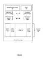
- FIG. 1Cshows a storage module ( 104 ), in accordance with one or more embodiments of the technology.
- the storage module ( 104 )includes a storage module controller ( 120 ), a buffer ( 122 ), one or more submission queues ( 124 A, 104 N), one or more completion queues ( 128 A, 128 N), and persistent storage ( 126 ). Each of these components is described below.
- the storage module controller ( 120 )is configured to receive and service requests to read from and/or write data to the persistent storage ( 122 ). These requests may originate from the clients ( 108 ) and may be conveyed to the storage module controller ( 120 ) via the fabric ( 106 ). Further, the storage module controller ( 124 ) may be programmed to, or otherwise configured to, perform all or a portion of the methods shown in FIGS. 4 and 5 .
- the storage module controller ( 120 )includes a processor (not shown) (e.g., one or more cores, or micro-cores of a processor that are configured to execute instructions), one or more hardware registers (not shown), and memory (shown) (e.g., volatile memory that may be, but is not limited to, dynamic random-access memory (DRAM), synchronous DRAM, SDR SDRAM, and DDR SDRAM) to perform all or a portion of the method described in FIGS. 4 and 5 .
- the storage module controller ( 120 )may be implemented using a field-programmable gate array (FPGA) and/or an application-specific integrated circuit (ASIC).
- FPGAfield-programmable gate array
- ASICapplication-specific integrated circuit
- the persistent storage ( 126 ) of the storage module ( 104 )may include, but is not limited to, Spin-Torque Magnetic RAM (ST-MRAM), Phase Change Memory (PCM), NAND Flash memory and NOR Flash memory.
- ST-MRAMSpin-Torque Magnetic RAM
- PCMPhase Change Memory
- NAND Flash memoryNAND Flash memory
- NOR Flash memoryNOR Flash memory
- the persistent storagestores data as objects. Accordingly, data may be written to and/or read from the objects by specifying an object identifier (ID) and an offset (i.e., an offset within the object).
- IDobject identifier
- offseti.e., an offset within the object
- the persistent storagemay be logically divided into a master partition ( 130 ) and one or more slave partitions ( 132 A, 132 M).
- the number of slave partitionscorresponds to the number of other storage modules on which a copy of data is to be stored. For example, consider a scenario in which there are three storage modules (SM 1 , SM 2 , SM 3 ) and a copy of the data is to be stored on each of the storage modules. In this example, one copy of the data may be stored in the master partition of SM 1 , a second copy of the data may be stored in a slave partition of SM 2 , and a third copy of the data may be stored in a slave partition of SM 3 .
- the storage modulesmaintain address mappings between address in a master partition and one or more addresses in the corresponding slave partitions (which are located on other storage modules).
- the persistent storageis logically partitioned (as described above), from the perspective of the clients ( FIG. 1, 108 ), the persistent storage appears as single unified address space. Said another way, the partitioning of the persistent storage is performed in a manner that is transparent to the clients.
- the buffer ( 122 )is volatile memory that temporarily stores data received by the storage module prior to the data being stored in the persistent storage.
- the storage modulemay include one or more submission queues ( 124 A, 124 N).
- the submission queuesstore commit requests in the order in which they are received by the storage module.
- the storage moduleincludes a single global submission queue in which all commit requests received from all clients are stored.
- the storage moduleincludes a set of submission queues, where each submission queue only stores commit requests received from a specific client and/or from a specific master storage module (see e.g., FIGS. 5 and 6 ).
- the storage modulemay include one or more completion queues ( 128 A, 128 N).
- the completion queuesstore commit replies received by the storage module from other storage module (see e.g., FIGS. 4-6 ).
- the storage moduleincludes a single global completion queue in which all commit replies received from all storage modules are stored.
- the storage moduleincludes a set of completion queues, where each completion queue only stores commit replies received from a specific storage module.
- the components of the storage appliance ( 100 )may include any number of storage modules ( 104 A- 104 N).
- the storage module controller ( 120 ) of the storage module ( 104 )may be equipped with central processing units (CPUs), field-programmable gate arrays (FPGAs), application-specific integrated circuits (ASICs) and/or any other type of processor, without departing from the technology.
- the fabricmay be based on communication standards other than those discussed above, without departing from the technology.
- FIGS. 2-5show flowcharts in accordance with one or more embodiments of the technology. While the various steps in the flowchart are presented and described sequentially, one of ordinary skill in the art will appreciate that some or all of the steps may be executed in different orders, may be combined or omitted, and some or all of the steps may be executed in parallel. In one embodiment of the technology, each of the steps shown in FIGS. 2-5 may be performed in parallel with any of the other steps shown in FIGS. 2-5 .
- FIG. 2shows a method for writing data to the storage modules from the perspective of a client in accordance with one or more embodiments of the technology.
- a clientIn Step 200 , a client generates a write request that includes an address and data.
- the address included in the write requestmay be a multicast address. More specifically, the address may appear, from the perspective of the client, as any other address; however, when this address is evaluated by the fabric, it results in the generation of N number of write requests (see e.g., FIG. 3 , step 304 ).
- the write requestis issued by the client to the fabric. If the fabric is a PCIe fabric (i.e., a fabric that implements PCIe), then the write request may be issued using one or more TLPs.
- the fabricis a PCIe fabric (i.e., a fabric that implements PCIe)
- the write requestmay be issued using one or more TLPs.
- the clientIn Step 204 , the client generates a commit request which includes an address. While the write request includes the data to be transmitted, the commit request includes the command which results in the data being stored in the persistent storage (see e.g., FIGS. 4, 5 ).
- the clientuses a consistent hashing function with the object identifier and offset as inputs to determine an address to use for the commit request. More specifically, commit requests for a specific object (identified using the object identifier) and offset are always sent to the same storage module (i.e., the “master storage module) for the ⁇ object ID, offset>).
- the consistent hashing functionis used to identify the master storage module.
- each clientimplements the same consistent hashing function, all commit requests for a specific ⁇ object ID, offset> as sent to the same storage module (i.e., the “master storage module) for the ⁇ object ID, offset> regardless of which client generates the commit request.
- the commit requestis sent to one of the storage modules that received the data via the write request.
- a multicast address associated with a multicast groupi.e., SM 1 , SM 2 , SM 3
- SM 1 , SM 2 , SM 3a multicast address associated with a multicast group
- SM 1 , SM 2 , SM 3a multicast address associated with a multicast group
- SM 3a consistent hashing function
- the commit requestis transmitted to SM 2 .
- the commit requestis issued by the client to the fabric. If the fabric is a PCIe fabric (i.e., a fabric that implements PCIe), then the commit request may be issued using one or more TLPs.
- the fabricis a PCIe fabric (i.e., a fabric that implements PCIe)
- the commit requestmay be issued using one or more TLPs.
- Step 208the client receives a commit reply from the fabric which originated from the storage module that received the commit request issued in Step 206 (assuming that the commit request was successfully processed and the fabric remains operational).
- FIG. 3shows a method for writing data to the storage modules from the perspective of the fabric in accordance with one or more embodiments of the technology.
- Step 300a write request that includes data and a multicast address is received by a leaf switch in the fabric. If the fabric is a PCIe fabric, then the write request may be received as one or a set of TLPs.
- the leaf switchprocesses the write request. More specifically, the processing of the write request includes evaluating the address in the write request to identify a hub tier switch (or an egress port operatively connected to the hub tier switch). The result of the processing is the transmission of the write request to a hub tier switch.
- a specific hub tier switchprocesses all write requests for a given address. For example, all write requests received by the fabric that include address A are routed to hub tier switch A.
- Step 304in response to receiving the write request, the hub tier switch processes the write request.
- the processing of the write requestincludes determining that the address in the write request is a multicast address and, in response to this determination, generating N number of write requests.
- the specific number (N) of write requests generatedis pre-configured on the hub tier switch.
- each of the generated write requestsincludes a unicast address.
- Step 306the generated write requests (i.e., the write requests generated in step 304 ) are transmitted to the storage modules. More specifically, each of the N write requests is transmitted to one of N storage modules in the storage appliance.
- Step 308a commit request corresponding to the write request (received in step 300 ) is received by a leaf switch in the fabric. If the fabric is a PCIe fabric, then the commit request may be received as one or a series of TLPs.
- Step 310the leaf switch processes the commit request.
- the result of the processingis the transmission of the commit request to a hub tier switch that is connected to the master storage module.
- Step 312in response to receiving the commit request, the hub tier switch processes the commit request.
- the result of the processingis the transmission of the commit request to master storage module (i.e., the master storage module for the ⁇ object ID, offset>).
- Step 314the fabric receives a commit reply from the master storage module.
- step 316the fabric transmits the commit reply to the client (assuming that fabric remains operational).
- FIG. 4shows a method for writing data to the storage modules from the perspective of a master storage module with a single global submission queue in accordance with one or more embodiments of the technology.
- Step 400a unicast write request is received from the fabric (i.e., a write request issued by the fabric in Step 306 ).
- Step 402the data associated with the write request is stored in a buffer of the “master” storage module.
- Step 404a unicast commit request is received from the fabric (i.e., a commit request issued by the fabric in Step 312 ).
- the unicast commit requestis placed in the single global submission queue.
- the commit requestincludes, or is otherwise associated with, a client identifier.
- the client identifieris used in the generation and/or processing of the corresponding commit reply (see e.g., FIG. 4 , step 414 ).
- Step 408the commit request in the global submission queue is processed based on a first-in first-out mechanism in order to preserve the processing order.
- the result of processing a commit requestis the storing of data in a location in a master partition in the persistent storage. Said another way, the order in which the data is written to the persistent storage is dictated by the order in which the commit requests are processed and not by the order in which the write requests (and/or data) is received by the storage module.
- N ⁇ 1 commit requestsare generated by the master storage module and transmitted, via the fabric, to N ⁇ 1 slave storage modules.
- N ⁇ 1 commit requestsare generated by the master storage module and transmitted, via the fabric, to N ⁇ 1 slave storage modules.
- N ⁇ 1 slave storage modulesFor example, consider a scenario in which there are three storage modules (SM 1 , SM 2 , SM 3 ) and a copy of the data is to be stored on each of the storage modules for ⁇ object ID 1, offset 3>. Further, assume that SM 1 is the master storage module for ⁇ object ID 1, offset 3>. In this scenario, SM 1 generates two commit requests—one to be sent to SM 2 and another to be sent to SM 3 .
- the storing of the data in the master partition of the persistent storage in step 408may be performed in parallel with step 410 .
- N ⁇ 1 commit repliesare received from the slave storage modules, via the fabric, and stored in a global completion queue on the master storage module.
- SM 1which is the master storage module in the example
- SM 3one commit reply from SM 2
- SM 3one commit reply from SM 3
- one or more commit repliesmay be received by the master storage module prior to all commit requests being transmitted to the slave storage modules.
- the master storage moduletransmit a commit request to slave storage module 1 and receive a corresponding commit reply from slave storage module 1 prior to sending a commit request to slave storage module 2 .
- a commit replyis generated and sent to the fabric by the master storage module.
- the commit replyis generated based, as least in part, on the client identifier associated with the corresponding commit request (i.e., the commit request received in step 404 ).
- a commit replymay only be generated by the master storage module if N ⁇ 1 commit replies are received from the N ⁇ 1 slave storage modules and the commit request in Step 408 was successfully processed by the master storage module.
- FIG. 5shows a method for writing data to the storage modules from the perspective of a slave storage module with a single global submission queue in accordance with one or more embodiments of the technology.
- Step 500a unicast write request is received from the fabric (i.e., a write request issued by the fabric in Step 306 ).
- Step 502the data associated with the write request is stored in a buffer of the storage module.
- Step 504a unicast commit request is received from the fabric (i.e., a commit request issued by the master storage module in Step 410 ).
- the unicast commit requestis placed in the single global submission queue.
- the commit requestincludes or is otherwise associated with a client identifier.
- the client identifieris used in the generation and/or processing of the corresponding commit reply (see e.g., FIG. 5 , step 510 ).
- Step 508the commit requests in the global submission queue are processed based on a first-in first-out mechanism in order to preserve the processing order. Said another way, the order in which the data is written to the persistent storage is dictated by the order in which the commit requests are processed and not by the order in which the write requests (and/or data) is received by the storage module.
- the result of processing a commit requestis the storing of data in the persistent storage. More specifically, consider a scenario in which a slave storage module received write request 1 (WR1) and subsequently commit request 1 (CR1) from a master storage module.
- the result of processing CR1is that data associated with WR1 is copied from a buffer in the storage module to a location in a corresponding slave partition in the persistent storage in the storage module.
- Step 510a commit reply corresponding to the commit request received in step 504 is generated and sent to the master storage module via the fabric.
- the commit replyis generated based, as least in part, on the client identifier associated with the corresponding commit request.
- steps 500 - 506are performed in parallel with steps 508 - 510 .
- steps 500 - 506result in the population of the global submission queue while steps 508 - 510 result in the processing of commit requests in the global submission queue.
- steps 500 - 506result in the population of the global submission queue while steps 508 - 510 result in the processing of commit requests in the global submission queue.
- steps 508 - 510result in the processing of commit requests in the global submission queue.
- the global submission queue for any storage modulemay include commit requests originating from one or more clients as well as commit requests originating from one or more master storage modules.
- the processing of the commit requestis performed in accordance with FIG. 4 while the processing of the commit request is performed in accordance with FIG. 5 if the commit request is received from a master storage module.
- FIGS. 4 and 5have been described with respect to using a single global submission queue in the master storage module and a single global submission queue in each of the slave storage modules, embodiments of the technology may be implemented using: (i) a set of submission queues and (ii) a set of completion queues.
- the set submission queuesmay include a per-client submission queue for each client and a per-master storage module submission queue for each master storage module from which commit requests are received.
- the set of completion queuesmay include a per-slave storage module completion queue for each slave storage module from which commit replies are received.
- each commit requestincludes, or is otherwise associated with, a global sequencing tag.
- the global sequencing tagsare used to maintain a global processing order of commit requests received by the storage module.
- the global sequencing tagmay be added to (or otherwise associated with) the commit request by a storage module controller.
- the commit requests in the per-client submission queuesare processed based on the global sequencing tags in order to preserve the global processing order in the storage module.
- submission queues and/or completion queuesmay be organized using other schemes without departing from the technology.
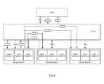
- FIG. 6shows an example system in accordance with one or more embodiments of the technology.
- the exampleis not intended to limit the scope of the technology.
- a clientwants to store three copies of data in a storage appliance.
- the clientissues a write request with a multicast address and data and transmits that request to the fabric.
- the fabricin response to receiving the write request generates and issues three write requests. This results in one copy of the data being stored in a buffer (not shown) in each of the storage modules (storage module 1 , storage module 2 , storage module 3 ).
- the clientsubsequently generates a commit request (commit request A).
- a commit request(commit request A).
- the master storage module(as determined using a consistent hashing function) is storage module 1 . Accordingly, the commit request is transmitted, via the fabric, to storage module 1 .
- storage module 1In response to receiving commit request A, storage module 1 stores commit request A in a submission queue (not shown) in storage module 1 . Commit request A is subsequently processed by storage module 1 resulting in a copy of the data (currently in the buffer in storage module 1 ) being stored in a location in master partition 1 A of the persistent storage in storage module 1 . Storage module 1 also generates two commit requests (commit request B, and commit request C). Storage module 1 then sends, via the fabric, commit request B to storage module 2 and commit request C to storage module 3 . As discussed above, the processing of commit request A may be performed in parallel with the generation and transmission of commit request B and commit request C.
- storage module 2In response to receiving commit request B, storage module 2 stores commit request B in a submission queue (not shown) in storage module 2 . Commit request B is subsequently processed by storage module 2 resulting in a copy of the data (currently in the buffer in storage module 2 ) being stored in a location in slave partition 2 A of the persistent storage in storage module 2 . After commit request B has been processed, storage module 2 generates and transmits, via the fabric, commit reply B to storage module 1 .
- storage module 3In response to receiving commit request C, storage module 3 stores commit request C in a submission queue (not shown) in storage module 3 . Commit request C is subsequently processed by storage module 3 resulting in a copy of the data (currently in the buffer in storage module 3 ) being stored in a location in slave partition 3 A of the persistent storage in storage module 3 . After commit request C has been processed, storage module 3 generates and transmits, via the fabric, commit reply C to storage module 1 .
- storage module 1receives and stores commit reply B and commit reply C in a completion queue. Once commit request A has been processed and commit replies B and C have been received, storage module A generates and transmits, via the fabric, commit reply A to the client.
Landscapes
- Engineering & Computer Science (AREA)
- Theoretical Computer Science (AREA)
- General Engineering & Computer Science (AREA)
- Physics & Mathematics (AREA)
- General Physics & Mathematics (AREA)
- Human Computer Interaction (AREA)
- Computer Hardware Design (AREA)
- Information Retrieval, Db Structures And Fs Structures Therefor (AREA)
Abstract
Description
Claims (16)
Priority Applications (2)
| Application Number | Priority Date | Filing Date | Title |
|---|---|---|---|
| US15/581,707US10614019B2 (en) | 2017-04-28 | 2017-04-28 | Method and system for fast ordered writes with target collaboration |
| CN201810390073.4ACN108804355B (en) | 2017-04-28 | 2018-04-27 | Method and system for fast ordering writes using target collaboration |
Applications Claiming Priority (1)
| Application Number | Priority Date | Filing Date | Title |
|---|---|---|---|
| US15/581,707US10614019B2 (en) | 2017-04-28 | 2017-04-28 | Method and system for fast ordered writes with target collaboration |
Publications (2)
| Publication Number | Publication Date |
|---|---|
| US20180314663A1 US20180314663A1 (en) | 2018-11-01 |
| US10614019B2true US10614019B2 (en) | 2020-04-07 |
Family
ID=63917282
Family Applications (1)
| Application Number | Title | Priority Date | Filing Date |
|---|---|---|---|
| US15/581,707ActiveUS10614019B2 (en) | 2017-04-28 | 2017-04-28 | Method and system for fast ordered writes with target collaboration |
Country Status (2)
| Country | Link |
|---|---|
| US (1) | US10614019B2 (en) |
| CN (1) | CN108804355B (en) |
Cited By (1)
| Publication number | Priority date | Publication date | Assignee | Title |
|---|---|---|---|---|
| US11880598B2 (en) | 2021-07-08 | 2024-01-23 | EMC IP Holding Company LLC | Request manager framework |
Families Citing this family (2)
| Publication number | Priority date | Publication date | Assignee | Title |
|---|---|---|---|---|
| US10564898B2 (en)* | 2018-06-11 | 2020-02-18 | Western Digital Technologies, Inc. | System and method for storage device management |
| US20220113974A1 (en)* | 2021-10-29 | 2022-04-14 | Intel Corporation | Hardware-software co-designed multi-cast for in-memory computing architectures |
Citations (82)
| Publication number | Priority date | Publication date | Assignee | Title |
|---|---|---|---|---|
| US5708668A (en) | 1992-05-06 | 1998-01-13 | International Business Machines Corporation | Method and apparatus for operating an array of storage devices |
| US6351838B1 (en) | 1999-03-12 | 2002-02-26 | Aurora Communications, Inc | Multidimensional parity protection system |
| US6415355B1 (en) | 1998-05-11 | 2002-07-02 | Kabushiki Kaisha Toshiba | Combined disk array controller and cache control method for parity generation mode and data restoration mode |
| US20020161972A1 (en) | 2001-04-30 | 2002-10-31 | Talagala Nisha D. | Data storage array employing block checksums and dynamic striping |
| US20030093740A1 (en) | 2001-10-19 | 2003-05-15 | Nebojsa Stojanovic | Iterative hard decoding method for multidimensional SPC |
| US20040153961A1 (en) | 2003-01-20 | 2004-08-05 | Samsung Electronics Co., Ltd. | Parity storing method and error block recovering method in external storage subsystem |
| US20040177219A1 (en) | 2002-11-06 | 2004-09-09 | Meehan Thomas F. | Method and apparatus for mechanically and electrically mounting a plurality of small form factor storage devices in place of a single larger form factor hard disk drive |
| US20040225926A1 (en) | 2003-04-26 | 2004-11-11 | International Business Machines Corporation | Configuring memory for a RAID storage system |
| US20050166083A1 (en) | 2003-06-26 | 2005-07-28 | Frey Alexander H.Jr. | RAID 6 disk array architectures |
| EP1577774A2 (en) | 2004-02-19 | 2005-09-21 | Nec Corporation | Semiconductor storage data striping |
| US20050223156A1 (en) | 2004-04-02 | 2005-10-06 | Lubbers Clark E | Storage media data structure system and method |
| US20050229023A1 (en) | 2004-04-02 | 2005-10-13 | Seagate Technology Llc | Dual redundant data storage format and method |
| US20060085594A1 (en) | 2004-10-20 | 2006-04-20 | Seagate Technology Llc | Metadata for a grid based data storage system |
| US20060112261A1 (en)* | 2004-11-22 | 2006-05-25 | Yourst Matt T | Method and apparatus for incremental commitment to architectural state in a microprocessor |
| US20060190243A1 (en) | 2005-02-24 | 2006-08-24 | Sharon Barkai | Method and apparatus for data management |
| US20070061383A1 (en)* | 2005-08-30 | 2007-03-15 | Yohsuke Ozawa | Fault recovery for transaction server |
| WO2008054760A2 (en) | 2006-10-31 | 2008-05-08 | Network Appliance, Inc. | System and method for optimizing write operations storage systems |
| US20080109602A1 (en) | 2006-11-03 | 2008-05-08 | Hewlett-Packard Development Company, L.P. | Method and apparatus for writing data to a disk array |
| US20080120484A1 (en) | 2006-11-17 | 2008-05-22 | Microsoft Corporation | Software transaction commit order and conflict management |
| US7398418B2 (en) | 2003-08-14 | 2008-07-08 | Compellent Technologies | Virtual disk drive system and method |
| US20080168225A1 (en) | 2007-01-10 | 2008-07-10 | International Business Machines Corporation | Providing enhanced tolerance of data loss in a disk array system |
| US7430706B1 (en) | 2004-03-01 | 2008-09-30 | Lattice Semiconductor Corporation | Diagonal interleaved parity calculator |
| US7543100B2 (en) | 2001-06-18 | 2009-06-02 | 3Par, Inc. | Node controller for a data storage system |
| US20090187786A1 (en) | 2008-01-17 | 2009-07-23 | Michael John Jones | Parity data management system apparatus and method |
| CN101604267A (en) | 2008-06-09 | 2009-12-16 | 普安科技股份有限公司 | Architecture of redundant array of independent disks |
| US7644197B1 (en) | 2003-10-15 | 2010-01-05 | Sun Microsystems, Inc. | Queue management by multiple processors |
| US20100005364A1 (en) | 2008-07-03 | 2010-01-07 | Seiji Higurashi | Encoding method, encoding apparatus, decoding method, and decoding apparatus using block code |
| US20100082540A1 (en)* | 2008-09-26 | 2010-04-01 | Isaacson Cory M | Scalable relational database replication |
| US7752389B1 (en) | 2007-06-20 | 2010-07-06 | Emc Corporation | Techniques for determining physical data layout of RAID devices |
| US20100199125A1 (en) | 2009-02-04 | 2010-08-05 | Micron Technology, Inc. | Systems and Methods for Storing and Recovering Controller Data in Non-Volatile Memory Devices |
| CN101980137A (en) | 2010-10-19 | 2011-02-23 | 成都市华为赛门铁克科技有限公司 | Inexpensive Disk Redundant Array Reconfiguration Method, Device and System |
| US20110055455A1 (en) | 2009-09-03 | 2011-03-03 | Apple Inc. | Incremental garbage collection for non-volatile memories |
| US7934120B2 (en) | 2006-09-11 | 2011-04-26 | International Business Machines Corporation | Storing data redundantly |
| US20110258347A1 (en)* | 2010-04-20 | 2011-10-20 | International Business Machines Corporation | Communications support in a transactional memory |
| US8078906B2 (en) | 2008-08-21 | 2011-12-13 | Infinidat, Ltd. | Grid storage system and method of operating thereof |
| US20120030425A1 (en) | 2010-07-30 | 2012-02-02 | International Business Machines Corporation | Parity declustered storage device array with partition groups |
| US8145840B2 (en) | 2009-06-05 | 2012-03-27 | Lsi Corporation | Method and system for storing excess data in a redundant array of independent disk level 6 |
| US20120079318A1 (en) | 2010-09-28 | 2012-03-29 | John Colgrove | Adaptive raid for an ssd environment |
| US20120089778A1 (en) | 2010-10-11 | 2012-04-12 | Intransa, Inc. | Storage system having cross node data redundancy and method and computer readable medium for same |
| US8200887B2 (en) | 2007-03-29 | 2012-06-12 | Violin Memory, Inc. | Memory management system and method |
| US20120166712A1 (en) | 2010-12-06 | 2012-06-28 | Xiotech Corporation | Hot sheet upgrade facility |
| US8289641B1 (en) | 2008-04-18 | 2012-10-16 | Network Appliance, Inc. | Partial data storage device failures and improved storage resiliency |
| US8316260B1 (en) | 2012-03-23 | 2012-11-20 | DSSD, Inc. | Method and system for multi-dimensional raid |
| US20120297118A1 (en) | 2011-05-17 | 2012-11-22 | Sergey Anatolievich Gorobets | Fast translation indicator to reduce secondary address table checks in a memory device |
| US20120303576A1 (en)* | 2011-05-23 | 2012-11-29 | Microsoft Corporation | Synchronous replication in a distributed storage environment |
| US20120324156A1 (en) | 2011-06-17 | 2012-12-20 | Naveen Muralimanohar | Method and system of organizing a heterogeneous memory architecture |
| US8352425B2 (en) | 2004-02-27 | 2013-01-08 | International Business Machines Corporation | Parallel apply processing in data replication with preservation of transaction integrity and source ordering of dependent updates |
| CN103019617A (en) | 2012-11-25 | 2013-04-03 | 向志华 | Establishing method for efficiently realizing internal RAID of SSD, data reading and writing method and device |
| US8464095B1 (en) | 2012-11-15 | 2013-06-11 | DSSD, Inc. | Method and system for multi-dimensional raid reconstruction and defect avoidance |
| US20130151754A1 (en) | 2011-12-12 | 2013-06-13 | Apple Inc. | Lba bitmap usage |
| US8489979B2 (en) | 2010-05-28 | 2013-07-16 | Seagate Technology Llc | Methods and devices to reduce outer code failure rate variability |
| US20130185735A1 (en) | 2012-01-18 | 2013-07-18 | International Business Machines Corporation | Warning track interruption facility |
| US8554997B1 (en) | 2013-01-18 | 2013-10-08 | DSSD, Inc. | Method and system for mirrored multi-dimensional raid |
| US8560772B1 (en) | 2010-12-29 | 2013-10-15 | Datadirect Networks, Inc. | System and method for data migration between high-performance computing architectures and data storage devices |
| CN103577111A (en) | 2012-07-23 | 2014-02-12 | 上海宝存信息科技有限公司 | Nonvolatile memory based dynamic redundant array of independent disks (RAID) storage system and method |
| US8719520B1 (en) | 2010-12-14 | 2014-05-06 | Datadirect Networks, Inc. | System and method for data migration between high-performance computing architectures and data storage devices with increased data reliability and integrity |
| US8725931B1 (en) | 2010-03-26 | 2014-05-13 | Western Digital Technologies, Inc. | System and method for managing the execution of memory commands in a solid-state memory |
| CN103902465A (en) | 2014-03-19 | 2014-07-02 | 华为技术有限公司 | Method, system and solid state disk controller for solid state disk garbage collection |
| US20140359608A1 (en) | 2013-05-28 | 2014-12-04 | Red Hat Israel, Ltd. | Systems and Methods for Timer Based Virtual Processor Scheduling |
| US8924776B1 (en) | 2013-12-04 | 2014-12-30 | DSSD, Inc. | Method and system for calculating parity values for multi-dimensional raid |
| US8977942B2 (en) | 2012-12-03 | 2015-03-10 | National Tsing Hua University | Data error-detection system and data error-detection method thereof |
| US9021183B2 (en) | 2010-12-24 | 2015-04-28 | Kabushiki Kaisha Toshiba | Data storage apparatus and apparatus and method for controlling nonvolatile memories |
| US20150324387A1 (en) | 2014-05-06 | 2015-11-12 | HGST Netherlands B.V. | Broadcast data operations in distributed file systems |
| US20160132432A1 (en) | 2014-11-06 | 2016-05-12 | Silicon Motion, Inc. | Methods for Caching and Reading Data to be Programmed into a Storage Unit and Apparatuses Using the Same |
| US20160148708A1 (en) | 2014-11-21 | 2016-05-26 | Sandisk Technologies Inc. | Defect Logging in Nonvolatile Memory |
| US20160210060A1 (en) | 2015-01-21 | 2016-07-21 | HGST Netherlands B.V. | Dynamic resource allocation within storage devices |
| US20160239421A1 (en) | 2015-02-12 | 2016-08-18 | International Business Machines Corporation | Memory nest efficiency with cache demand generation |
| US20160239345A1 (en) | 2015-02-13 | 2016-08-18 | Honeywell International, Inc. | Apparatus and method for managing a plurality of threads in an operating system |
| US20160320986A1 (en) | 2015-04-29 | 2016-11-03 | Emc Corporation | Method and system for replicating and using grid level metadata in a storage system |
| US9529674B2 (en) | 2013-06-18 | 2016-12-27 | Dell Product, LP | Storage device management of unrecoverable logical block addresses for RAID data regeneration |
| US9552242B1 (en) | 2013-09-25 | 2017-01-24 | Amazon Technologies, Inc. | Log-structured distributed storage using a single log sequence number space |
| US20170124327A1 (en) | 2015-10-31 | 2017-05-04 | Quick Heal Technologies Private Limited | Detecting malware when executing in a system |
| US20170192889A1 (en)* | 2016-01-04 | 2017-07-06 | Kabushiki Kaisha Toshiba | Parallel processing of a series of data units for writing |
| US20170255405A1 (en) | 2016-03-07 | 2017-09-07 | Kabushiki Kaisha Toshiba | Memory system |
| US9760493B1 (en) | 2016-03-14 | 2017-09-12 | Vmware, Inc. | System and methods of a CPU-efficient cache replacement algorithm |
| US20170285945A1 (en) | 2016-04-01 | 2017-10-05 | Sk Hynix Memory Solutions Inc. | Throttling for a memory system and operating method thereof |
| US20170300249A1 (en) | 2016-04-15 | 2017-10-19 | Western Digital Technologies, Inc. | Validity tracking for garbage collection |
| US20170329675A1 (en)* | 2016-05-10 | 2017-11-16 | International Business Machines Corporation | Generating a chain of a plurality of write requests |
| US20170351604A1 (en) | 2016-06-02 | 2017-12-07 | Futurewei Technologies, Inc. | Host and garbage collection write ratio controller |
| US20180032333A1 (en) | 2016-07-31 | 2018-02-01 | Mark Kenneth Sullivan | Atomic Line Multi-Tasking |
| US20180150326A1 (en) | 2015-07-29 | 2018-05-31 | Alibaba Group Holding Limited | Method and apparatus for executing task in cluster |
| US20180267897A1 (en) | 2017-03-14 | 2018-09-20 | SK Hynix Inc. | Memory system and operating method thereof |
Family Cites Families (3)
| Publication number | Priority date | Publication date | Assignee | Title |
|---|---|---|---|---|
| WO2008117379A1 (en)* | 2007-03-23 | 2008-10-02 | Fujitsu Limited | Method for measuring transmission quality of packet, device for measuring transmission of packet, and device for measuring reception of packet |
| US9389787B2 (en)* | 2014-05-15 | 2016-07-12 | Netapp, Inc. | System and method for simulating a persistent byte addressable storage device on a persistent block addressable storage device |
| US9864710B2 (en)* | 2015-03-30 | 2018-01-09 | EMC IP Holding Company LLC | Writing data to storage via a PCI express fabric having a fully-connected mesh topology |
- 2017
- 2017-04-28USUS15/581,707patent/US10614019B2/enactiveActive
- 2018
- 2018-04-27CNCN201810390073.4Apatent/CN108804355B/enactiveActive
Patent Citations (93)
| Publication number | Priority date | Publication date | Assignee | Title |
|---|---|---|---|---|
| US5708668A (en) | 1992-05-06 | 1998-01-13 | International Business Machines Corporation | Method and apparatus for operating an array of storage devices |
| US6415355B1 (en) | 1998-05-11 | 2002-07-02 | Kabushiki Kaisha Toshiba | Combined disk array controller and cache control method for parity generation mode and data restoration mode |
| US6351838B1 (en) | 1999-03-12 | 2002-02-26 | Aurora Communications, Inc | Multidimensional parity protection system |
| US20020161972A1 (en) | 2001-04-30 | 2002-10-31 | Talagala Nisha D. | Data storage array employing block checksums and dynamic striping |
| US7543100B2 (en) | 2001-06-18 | 2009-06-02 | 3Par, Inc. | Node controller for a data storage system |
| US20030093740A1 (en) | 2001-10-19 | 2003-05-15 | Nebojsa Stojanovic | Iterative hard decoding method for multidimensional SPC |
| US20040177219A1 (en) | 2002-11-06 | 2004-09-09 | Meehan Thomas F. | Method and apparatus for mechanically and electrically mounting a plurality of small form factor storage devices in place of a single larger form factor hard disk drive |
| US20040153961A1 (en) | 2003-01-20 | 2004-08-05 | Samsung Electronics Co., Ltd. | Parity storing method and error block recovering method in external storage subsystem |
| JP2004326759A (en) | 2003-04-26 | 2004-11-18 | Internatl Business Mach Corp <Ibm> | Constitution of memory for raid storage system |
| US20040225926A1 (en) | 2003-04-26 | 2004-11-11 | International Business Machines Corporation | Configuring memory for a RAID storage system |
| US20050166083A1 (en) | 2003-06-26 | 2005-07-28 | Frey Alexander H.Jr. | RAID 6 disk array architectures |
| US7398418B2 (en) | 2003-08-14 | 2008-07-08 | Compellent Technologies | Virtual disk drive system and method |
| US7644197B1 (en) | 2003-10-15 | 2010-01-05 | Sun Microsystems, Inc. | Queue management by multiple processors |
| EP1577774A2 (en) | 2004-02-19 | 2005-09-21 | Nec Corporation | Semiconductor storage data striping |
| US8352425B2 (en) | 2004-02-27 | 2013-01-08 | International Business Machines Corporation | Parallel apply processing in data replication with preservation of transaction integrity and source ordering of dependent updates |
| US7430706B1 (en) | 2004-03-01 | 2008-09-30 | Lattice Semiconductor Corporation | Diagonal interleaved parity calculator |
| US20050223156A1 (en) | 2004-04-02 | 2005-10-06 | Lubbers Clark E | Storage media data structure system and method |
| US20050229023A1 (en) | 2004-04-02 | 2005-10-13 | Seagate Technology Llc | Dual redundant data storage format and method |
| US7406621B2 (en) | 2004-04-02 | 2008-07-29 | Seagate Technology Llc | Dual redundant data storage format and method |
| US20060085594A1 (en) | 2004-10-20 | 2006-04-20 | Seagate Technology Llc | Metadata for a grid based data storage system |
| US20060112261A1 (en)* | 2004-11-22 | 2006-05-25 | Yourst Matt T | Method and apparatus for incremental commitment to architectural state in a microprocessor |
| US20060190243A1 (en) | 2005-02-24 | 2006-08-24 | Sharon Barkai | Method and apparatus for data management |
| US20070061383A1 (en)* | 2005-08-30 | 2007-03-15 | Yohsuke Ozawa | Fault recovery for transaction server |
| US7934120B2 (en) | 2006-09-11 | 2011-04-26 | International Business Machines Corporation | Storing data redundantly |
| WO2008054760A2 (en) | 2006-10-31 | 2008-05-08 | Network Appliance, Inc. | System and method for optimizing write operations storage systems |
| JP2010508604A (en) | 2006-10-31 | 2010-03-18 | ネットアップ,インコーポレイテッド | System and method for optimizing write processing in a storage system |
| US20080109602A1 (en) | 2006-11-03 | 2008-05-08 | Hewlett-Packard Development Company, L.P. | Method and apparatus for writing data to a disk array |
| US20080120484A1 (en) | 2006-11-17 | 2008-05-22 | Microsoft Corporation | Software transaction commit order and conflict management |
| US20080168225A1 (en) | 2007-01-10 | 2008-07-10 | International Business Machines Corporation | Providing enhanced tolerance of data loss in a disk array system |
| US8200887B2 (en) | 2007-03-29 | 2012-06-12 | Violin Memory, Inc. | Memory management system and method |
| US7752389B1 (en) | 2007-06-20 | 2010-07-06 | Emc Corporation | Techniques for determining physical data layout of RAID devices |
| US20090187786A1 (en) | 2008-01-17 | 2009-07-23 | Michael John Jones | Parity data management system apparatus and method |
| US8289641B1 (en) | 2008-04-18 | 2012-10-16 | Network Appliance, Inc. | Partial data storage device failures and improved storage resiliency |
| US8234445B2 (en) | 2008-06-09 | 2012-07-31 | Infortrend Technology, Inc. | RAID data protection architecture using data protection information |
| CN101604267A (en) | 2008-06-09 | 2009-12-16 | 普安科技股份有限公司 | Architecture of redundant array of independent disks |
| US20100005364A1 (en) | 2008-07-03 | 2010-01-07 | Seiji Higurashi | Encoding method, encoding apparatus, decoding method, and decoding apparatus using block code |
| US8078906B2 (en) | 2008-08-21 | 2011-12-13 | Infinidat, Ltd. | Grid storage system and method of operating thereof |
| US20100082540A1 (en)* | 2008-09-26 | 2010-04-01 | Isaacson Cory M | Scalable relational database replication |
| US20100199125A1 (en) | 2009-02-04 | 2010-08-05 | Micron Technology, Inc. | Systems and Methods for Storing and Recovering Controller Data in Non-Volatile Memory Devices |
| US8145840B2 (en) | 2009-06-05 | 2012-03-27 | Lsi Corporation | Method and system for storing excess data in a redundant array of independent disk level 6 |
| US20110055455A1 (en) | 2009-09-03 | 2011-03-03 | Apple Inc. | Incremental garbage collection for non-volatile memories |
| US8725931B1 (en) | 2010-03-26 | 2014-05-13 | Western Digital Technologies, Inc. | System and method for managing the execution of memory commands in a solid-state memory |
| US20110258347A1 (en)* | 2010-04-20 | 2011-10-20 | International Business Machines Corporation | Communications support in a transactional memory |
| US8782505B2 (en) | 2010-05-28 | 2014-07-15 | Seagate Technology Llc | Methods and devices to reduce outer code failure rate variability |
| US8489979B2 (en) | 2010-05-28 | 2013-07-16 | Seagate Technology Llc | Methods and devices to reduce outer code failure rate variability |
| US20120030425A1 (en) | 2010-07-30 | 2012-02-02 | International Business Machines Corporation | Parity declustered storage device array with partition groups |
| US20120079318A1 (en) | 2010-09-28 | 2012-03-29 | John Colgrove | Adaptive raid for an ssd environment |
| US20120089778A1 (en) | 2010-10-11 | 2012-04-12 | Intransa, Inc. | Storage system having cross node data redundancy and method and computer readable medium for same |
| CN101980137A (en) | 2010-10-19 | 2011-02-23 | 成都市华为赛门铁克科技有限公司 | Inexpensive Disk Redundant Array Reconfiguration Method, Device and System |
| US8843782B2 (en) | 2010-10-19 | 2014-09-23 | Huawei Technologies Co., Ltd. | Method and apparatus for reconstructing redundant array of inexpensive disks, and system |
| US20120166712A1 (en) | 2010-12-06 | 2012-06-28 | Xiotech Corporation | Hot sheet upgrade facility |
| US8719520B1 (en) | 2010-12-14 | 2014-05-06 | Datadirect Networks, Inc. | System and method for data migration between high-performance computing architectures and data storage devices with increased data reliability and integrity |
| US9021183B2 (en) | 2010-12-24 | 2015-04-28 | Kabushiki Kaisha Toshiba | Data storage apparatus and apparatus and method for controlling nonvolatile memories |
| US8560772B1 (en) | 2010-12-29 | 2013-10-15 | Datadirect Networks, Inc. | System and method for data migration between high-performance computing architectures and data storage devices |
| US20120297118A1 (en) | 2011-05-17 | 2012-11-22 | Sergey Anatolievich Gorobets | Fast translation indicator to reduce secondary address table checks in a memory device |
| US20120303576A1 (en)* | 2011-05-23 | 2012-11-29 | Microsoft Corporation | Synchronous replication in a distributed storage environment |
| US20120324156A1 (en) | 2011-06-17 | 2012-12-20 | Naveen Muralimanohar | Method and system of organizing a heterogeneous memory architecture |
| US20130151754A1 (en) | 2011-12-12 | 2013-06-13 | Apple Inc. | Lba bitmap usage |
| US20130185735A1 (en) | 2012-01-18 | 2013-07-18 | International Business Machines Corporation | Warning track interruption facility |
| US8316260B1 (en) | 2012-03-23 | 2012-11-20 | DSSD, Inc. | Method and system for multi-dimensional raid |
| US8448021B1 (en) | 2012-03-23 | 2013-05-21 | DSSD, Inc. | Method and system for multi-dimensional raid |
| US8327185B1 (en) | 2012-03-23 | 2012-12-04 | DSSD, Inc. | Method and system for multi-dimensional raid |
| CN103577111A (en) | 2012-07-23 | 2014-02-12 | 上海宝存信息科技有限公司 | Nonvolatile memory based dynamic redundant array of independent disks (RAID) storage system and method |
| CN104871138A (en) | 2012-11-15 | 2015-08-26 | Dssd股份有限公司 | Method and system for multi-dimensional raid reconstruction and defect avoidance |
| US8464095B1 (en) | 2012-11-15 | 2013-06-11 | DSSD, Inc. | Method and system for multi-dimensional raid reconstruction and defect avoidance |
| CN103019617A (en) | 2012-11-25 | 2013-04-03 | 向志华 | Establishing method for efficiently realizing internal RAID of SSD, data reading and writing method and device |
| US8977942B2 (en) | 2012-12-03 | 2015-03-10 | National Tsing Hua University | Data error-detection system and data error-detection method thereof |
| US8554997B1 (en) | 2013-01-18 | 2013-10-08 | DSSD, Inc. | Method and system for mirrored multi-dimensional raid |
| US20140359608A1 (en) | 2013-05-28 | 2014-12-04 | Red Hat Israel, Ltd. | Systems and Methods for Timer Based Virtual Processor Scheduling |
| US9529674B2 (en) | 2013-06-18 | 2016-12-27 | Dell Product, LP | Storage device management of unrecoverable logical block addresses for RAID data regeneration |
| US9552242B1 (en) | 2013-09-25 | 2017-01-24 | Amazon Technologies, Inc. | Log-structured distributed storage using a single log sequence number space |
| US8924776B1 (en) | 2013-12-04 | 2014-12-30 | DSSD, Inc. | Method and system for calculating parity values for multi-dimensional raid |
| US9152499B1 (en) | 2013-12-04 | 2015-10-06 | DSSD, Inc. | Method and system for calculating parity values for multi-dimensional RAID |
| CN103902465A (en) | 2014-03-19 | 2014-07-02 | 华为技术有限公司 | Method, system and solid state disk controller for solid state disk garbage collection |
| US20150324387A1 (en) | 2014-05-06 | 2015-11-12 | HGST Netherlands B.V. | Broadcast data operations in distributed file systems |
| US20160132432A1 (en) | 2014-11-06 | 2016-05-12 | Silicon Motion, Inc. | Methods for Caching and Reading Data to be Programmed into a Storage Unit and Apparatuses Using the Same |
| US20160148708A1 (en) | 2014-11-21 | 2016-05-26 | Sandisk Technologies Inc. | Defect Logging in Nonvolatile Memory |
| US20160210060A1 (en) | 2015-01-21 | 2016-07-21 | HGST Netherlands B.V. | Dynamic resource allocation within storage devices |
| US20160239421A1 (en) | 2015-02-12 | 2016-08-18 | International Business Machines Corporation | Memory nest efficiency with cache demand generation |
| US20160239345A1 (en) | 2015-02-13 | 2016-08-18 | Honeywell International, Inc. | Apparatus and method for managing a plurality of threads in an operating system |
| US20160320986A1 (en) | 2015-04-29 | 2016-11-03 | Emc Corporation | Method and system for replicating and using grid level metadata in a storage system |
| US20180150326A1 (en) | 2015-07-29 | 2018-05-31 | Alibaba Group Holding Limited | Method and apparatus for executing task in cluster |
| US20170124327A1 (en) | 2015-10-31 | 2017-05-04 | Quick Heal Technologies Private Limited | Detecting malware when executing in a system |
| US20170192889A1 (en)* | 2016-01-04 | 2017-07-06 | Kabushiki Kaisha Toshiba | Parallel processing of a series of data units for writing |
| US20170255405A1 (en) | 2016-03-07 | 2017-09-07 | Kabushiki Kaisha Toshiba | Memory system |
| US10095414B2 (en) | 2016-03-07 | 2018-10-09 | Toshiba Memory Corporation | Memory system including a controller and a nonvolatile memory having memory blocks |
| US9760493B1 (en) | 2016-03-14 | 2017-09-12 | Vmware, Inc. | System and methods of a CPU-efficient cache replacement algorithm |
| US20170285945A1 (en) | 2016-04-01 | 2017-10-05 | Sk Hynix Memory Solutions Inc. | Throttling for a memory system and operating method thereof |
| US20170300249A1 (en) | 2016-04-15 | 2017-10-19 | Western Digital Technologies, Inc. | Validity tracking for garbage collection |
| US20170329675A1 (en)* | 2016-05-10 | 2017-11-16 | International Business Machines Corporation | Generating a chain of a plurality of write requests |
| US20170351604A1 (en) | 2016-06-02 | 2017-12-07 | Futurewei Technologies, Inc. | Host and garbage collection write ratio controller |
| US20180032333A1 (en) | 2016-07-31 | 2018-02-01 | Mark Kenneth Sullivan | Atomic Line Multi-Tasking |
| US20180267897A1 (en) | 2017-03-14 | 2018-09-20 | SK Hynix Inc. | Memory system and operating method thereof |
Non-Patent Citations (10)
| Title |
|---|
| Akber Kazmi; "PCI Express™ Basics & Applications in Communication Systems"; PCI-SIG Developers Conference; 2004 (50 pages). |
| Amber Huffman; "NVM Express: Revision 1.0b"; Jul. 12, 2011 (126 pages). |
| Decision to Grant a Patent issued in corresponding Japanese Application No. 2015-501902, dated May 31, 2016 (6 pages). |
| Definition: time slice: IBM knowledgebase, "Scheduler Processor Time Slice", retrieved on-line at http://www.ibm.com/support/knowledgecenter/en/ssw_aix_72/com.ibm.aix.performance/sched_proc_time_slice.htm, retrieved on Jun. 11, 2019 (2 pages). |
| Definition: time slice: Microsoft computer dictionary, Fifth Edition. p. 656, 2015 Safari Books Online, LLC., (1 page). |
| Definition: time slice: Wikipedia: retrieved on-line at https://en.wikipedia.org/wiki/Preemtion_(computing), on Jul. 11, 2019. (3 pages). |
| Derek Percival; "Multicast Over PCI Express®," PCI-SIG Developers Conference Europe; 2009 (33 pages). |
| H. Peter Anvin; "The mathematics of RAID-6"; http://kernel.org/pub/linux/kernel/people/hpa/raid6.pdf (last visited Nov. 15, 2017) (9 pages). |
| Jack Regula; "Using Non-transparent Bridging in PCI Express Systems"; PLX Technology, Inc.; Jun. 1, 2004 (31 pages). |
| Minoru Uehara; "Orthogonal RAID with Multiple Parties in Virtual Large-Scale Disks"; IPSJ SIG Technical Report; vol. 2011-DPS-149; No. 4; Nov. 24, 2011 (8 pages). |
Cited By (1)
| Publication number | Priority date | Publication date | Assignee | Title |
|---|---|---|---|---|
| US11880598B2 (en) | 2021-07-08 | 2024-01-23 | EMC IP Holding Company LLC | Request manager framework |
Also Published As
| Publication number | Publication date |
|---|---|
| CN108804355A (en) | 2018-11-13 |
| CN108804355B (en) | 2023-11-07 |
| US20180314663A1 (en) | 2018-11-01 |
Similar Documents
| Publication | Publication Date | Title |
|---|---|---|
| KR102427561B1 (en) | A novel ssd architecture for fpga based acceleration | |
| EP3089045B1 (en) | Multi-bank memory with one read port and one or more write ports per cycle | |
| US9921756B2 (en) | Method and system for synchronizing an index of data blocks stored in a storage system using a shared storage module | |
| US9507531B1 (en) | Method and system for hybrid direct input/output (I/O) with a storage device | |
| JP2016036149A (en) | Pciexpress fabric routing for sufficiently connected mesh topology | |
| US10338813B2 (en) | Storage controller and using method therefor | |
| US10614019B2 (en) | Method and system for fast ordered writes with target collaboration | |
| CN108139882A (en) | Systems and methods for implementing hierarchical distributed linked lists for network devices | |
| CN107430584B (en) | Reading data from storage via PCI EXPRESS fabric with fully connected mesh topology | |
| CN107533536A (en) | Techniques for Scalable Remotely Accessible Memory Segments | |
| US20190042133A1 (en) | Technologies for providing adaptive data access request routing in a distributed storage system | |
| US11874780B2 (en) | Packet processing system, method and device utilizing a port client chain | |
| CN105930545A (en) | Method and device for migrating files | |
| CN107533526B (en) | Writing data to storage via PCI EXPRESS fabric with fully connected mesh topology | |
| KR20190112020A (en) | Data processing | |
| US9875190B2 (en) | Delegated media translation layer in a storage appliance | |
| CN108804342B (en) | Method and system for writing and reading data to and from a persistent storage device | |
| US10466930B2 (en) | Method and system for fast ordered writes with atomic multicast | |
| CN105765542B (en) | Method for accessing files, distributed storage system and storage nodes | |
| US10558387B2 (en) | Method and system for optimistic flow control for push-based input/output with buffer stealing | |
| CN110865771B (en) | A data storage method and device | |
| WO2016065612A1 (en) | Method, system, and host for accessing files |
Legal Events
| Date | Code | Title | Description |
|---|---|---|---|
| AS | Assignment | Owner name:EMC IP HOLDING COMPANY LLC, MASSACHUSETTS Free format text:ASSIGNMENT OF ASSIGNORS INTEREST;ASSIGNORS:NISHIMOTO, MICHAEL;RAJADNYA, SAMIR;SIGNING DATES FROM 20171209 TO 20171213;REEL/FRAME:044958/0538 | |
| STPP | Information on status: patent application and granting procedure in general | Free format text:FINAL REJECTION MAILED | |
| AS | Assignment | Owner name:THE BANK OF NEW YORK MELLON TRUST COMPANY, N.A., T Free format text:SECURITY AGREEMENT;ASSIGNORS:CREDANT TECHNOLOGIES, INC.;DELL INTERNATIONAL L.L.C.;DELL MARKETING L.P.;AND OTHERS;REEL/FRAME:049452/0223 Effective date:20190320 Owner name:THE BANK OF NEW YORK MELLON TRUST COMPANY, N.A., TEXAS Free format text:SECURITY AGREEMENT;ASSIGNORS:CREDANT TECHNOLOGIES, INC.;DELL INTERNATIONAL L.L.C.;DELL MARKETING L.P.;AND OTHERS;REEL/FRAME:049452/0223 Effective date:20190320 | |
| AS | Assignment | Owner name:CREDIT SUISSE AG, CAYMAN ISLANDS BRANCH, NORTH CAR Free format text:SECURITY AGREEMENT;ASSIGNORS:DELL PRODUCTS L.P.;EMC CORPORATION;EMC IP HOLDING COMPANY LLC;REEL/FRAME:048825/0489 Effective date:20190405 Owner name:CREDIT SUISSE AG, CAYMAN ISLANDS BRANCH, NORTH CAROLINA Free format text:SECURITY AGREEMENT;ASSIGNORS:DELL PRODUCTS L.P.;EMC CORPORATION;EMC IP HOLDING COMPANY LLC;REEL/FRAME:048825/0489 Effective date:20190405 | |
| STPP | Information on status: patent application and granting procedure in general | Free format text:DOCKETED NEW CASE - READY FOR EXAMINATION | |
| STPP | Information on status: patent application and granting procedure in general | Free format text:NOTICE OF ALLOWANCE MAILED -- APPLICATION RECEIVED IN OFFICE OF PUBLICATIONS | |
| STPP | Information on status: patent application and granting procedure in general | Free format text:PUBLICATIONS -- ISSUE FEE PAYMENT VERIFIED | |
| STCF | Information on status: patent grant | Free format text:PATENTED CASE | |
| AS | Assignment | Owner name:THE BANK OF NEW YORK MELLON TRUST COMPANY, N.A., TEXAS Free format text:SECURITY AGREEMENT;ASSIGNORS:CREDANT TECHNOLOGIES INC.;DELL INTERNATIONAL L.L.C.;DELL MARKETING L.P.;AND OTHERS;REEL/FRAME:053546/0001 Effective date:20200409 | |
| AS | Assignment | Owner name:EMC IP HOLDING COMPANY LLC, TEXAS Free format text:RELEASE OF SECURITY INTEREST AT REEL 048825 FRAME 0489;ASSIGNOR:CREDIT SUISSE AG, CAYMAN ISLANDS BRANCH;REEL/FRAME:058000/0916 Effective date:20211101 Owner name:EMC CORPORATION, MASSACHUSETTS Free format text:RELEASE OF SECURITY INTEREST AT REEL 048825 FRAME 0489;ASSIGNOR:CREDIT SUISSE AG, CAYMAN ISLANDS BRANCH;REEL/FRAME:058000/0916 Effective date:20211101 Owner name:DELL PRODUCTS L.P., TEXAS Free format text:RELEASE OF SECURITY INTEREST AT REEL 048825 FRAME 0489;ASSIGNOR:CREDIT SUISSE AG, CAYMAN ISLANDS BRANCH;REEL/FRAME:058000/0916 Effective date:20211101 | |
| AS | Assignment | Owner name:DELL MARKETING L.P. (ON BEHALF OF ITSELF AND AS SUCCESSOR-IN-INTEREST TO CREDANT TECHNOLOGIES, INC.), TEXAS Free format text:RELEASE OF SECURITY INTEREST IN PATENTS PREVIOUSLY RECORDED AT REEL/FRAME (053546/0001);ASSIGNOR:THE BANK OF NEW YORK MELLON TRUST COMPANY, N.A., AS NOTES COLLATERAL AGENT;REEL/FRAME:071642/0001 Effective date:20220329 Owner name:DELL INTERNATIONAL L.L.C., TEXAS Free format text:RELEASE OF SECURITY INTEREST IN PATENTS PREVIOUSLY RECORDED AT REEL/FRAME (053546/0001);ASSIGNOR:THE BANK OF NEW YORK MELLON TRUST COMPANY, N.A., AS NOTES COLLATERAL AGENT;REEL/FRAME:071642/0001 Effective date:20220329 Owner name:DELL PRODUCTS L.P., TEXAS Free format text:RELEASE OF SECURITY INTEREST IN PATENTS PREVIOUSLY RECORDED AT REEL/FRAME (053546/0001);ASSIGNOR:THE BANK OF NEW YORK MELLON TRUST COMPANY, N.A., AS NOTES COLLATERAL AGENT;REEL/FRAME:071642/0001 Effective date:20220329 Owner name:DELL USA L.P., TEXAS Free format text:RELEASE OF SECURITY INTEREST IN PATENTS PREVIOUSLY RECORDED AT REEL/FRAME (053546/0001);ASSIGNOR:THE BANK OF NEW YORK MELLON TRUST COMPANY, N.A., AS NOTES COLLATERAL AGENT;REEL/FRAME:071642/0001 Effective date:20220329 Owner name:EMC CORPORATION, MASSACHUSETTS Free format text:RELEASE OF SECURITY INTEREST IN PATENTS PREVIOUSLY RECORDED AT REEL/FRAME (053546/0001);ASSIGNOR:THE BANK OF NEW YORK MELLON TRUST COMPANY, N.A., AS NOTES COLLATERAL AGENT;REEL/FRAME:071642/0001 Effective date:20220329 Owner name:DELL MARKETING CORPORATION (SUCCESSOR-IN-INTEREST TO FORCE10 NETWORKS, INC. AND WYSE TECHNOLOGY L.L.C.), TEXAS Free format text:RELEASE OF SECURITY INTEREST IN PATENTS PREVIOUSLY RECORDED AT REEL/FRAME (053546/0001);ASSIGNOR:THE BANK OF NEW YORK MELLON TRUST COMPANY, N.A., AS NOTES COLLATERAL AGENT;REEL/FRAME:071642/0001 Effective date:20220329 Owner name:EMC IP HOLDING COMPANY LLC, TEXAS Free format text:RELEASE OF SECURITY INTEREST IN PATENTS PREVIOUSLY RECORDED AT REEL/FRAME (053546/0001);ASSIGNOR:THE BANK OF NEW YORK MELLON TRUST COMPANY, N.A., AS NOTES COLLATERAL AGENT;REEL/FRAME:071642/0001 Effective date:20220329 | |
| MAFP | Maintenance fee payment | Free format text:PAYMENT OF MAINTENANCE FEE, 4TH YEAR, LARGE ENTITY (ORIGINAL EVENT CODE: M1551); ENTITY STATUS OF PATENT OWNER: LARGE ENTITY Year of fee payment:4 |