US10613196B2 - Apparatus for processing signals of radar and method for processing signals thereof - Google Patents
Apparatus for processing signals of radar and method for processing signals thereofDownload PDFInfo
- Publication number
- US10613196B2 US10613196B2US15/177,330US201615177330AUS10613196B2US 10613196 B2US10613196 B2US 10613196B2US 201615177330 AUS201615177330 AUS 201615177330AUS 10613196 B2US10613196 B2US 10613196B2
- Authority
- US
- United States
- Prior art keywords
- target
- signal processing
- clutter
- vehicle
- processing unit
- Prior art date
- Legal status (The legal status is an assumption and is not a legal conclusion. Google has not performed a legal analysis and makes no representation as to the accuracy of the status listed.)
- Active, expires
Links
- 238000000034methodMethods0.000titleclaimsdescription9
- 238000003672processing methodMethods0.000claimsabstractdescription11
- 238000010586diagramMethods0.000description10
- 238000001514detection methodMethods0.000description7
- 239000000284extractSubstances0.000description7
- 230000010363phase shiftEffects0.000description2
- 230000003044adaptive effectEffects0.000description1
- 238000000605extractionMethods0.000description1
- 230000010354integrationEffects0.000description1
Images


Classifications
- G—PHYSICS
- G01—MEASURING; TESTING
- G01S—RADIO DIRECTION-FINDING; RADIO NAVIGATION; DETERMINING DISTANCE OR VELOCITY BY USE OF RADIO WAVES; LOCATING OR PRESENCE-DETECTING BY USE OF THE REFLECTION OR RERADIATION OF RADIO WAVES; ANALOGOUS ARRANGEMENTS USING OTHER WAVES
- G01S7/00—Details of systems according to groups G01S13/00, G01S15/00, G01S17/00
- G01S7/02—Details of systems according to groups G01S13/00, G01S15/00, G01S17/00 of systems according to group G01S13/00
- G01S7/41—Details of systems according to groups G01S13/00, G01S15/00, G01S17/00 of systems according to group G01S13/00 using analysis of echo signal for target characterisation; Target signature; Target cross-section
- G01S7/411—Identification of targets based on measurements of radar reflectivity
- G—PHYSICS
- G01—MEASURING; TESTING
- G01S—RADIO DIRECTION-FINDING; RADIO NAVIGATION; DETERMINING DISTANCE OR VELOCITY BY USE OF RADIO WAVES; LOCATING OR PRESENCE-DETECTING BY USE OF THE REFLECTION OR RERADIATION OF RADIO WAVES; ANALOGOUS ARRANGEMENTS USING OTHER WAVES
- G01S7/00—Details of systems according to groups G01S13/00, G01S15/00, G01S17/00
- G01S7/02—Details of systems according to groups G01S13/00, G01S15/00, G01S17/00 of systems according to group G01S13/00
- G01S7/28—Details of pulse systems
- G01S7/285—Receivers
- G01S7/34—Gain of receiver varied automatically during pulse-recurrence period, e.g. anti-clutter gain control
- G—PHYSICS
- G01—MEASURING; TESTING
- G01S—RADIO DIRECTION-FINDING; RADIO NAVIGATION; DETERMINING DISTANCE OR VELOCITY BY USE OF RADIO WAVES; LOCATING OR PRESENCE-DETECTING BY USE OF THE REFLECTION OR RERADIATION OF RADIO WAVES; ANALOGOUS ARRANGEMENTS USING OTHER WAVES
- G01S13/00—Systems using the reflection or reradiation of radio waves, e.g. radar systems; Analogous systems using reflection or reradiation of waves whose nature or wavelength is irrelevant or unspecified
- G01S13/02—Systems using reflection of radio waves, e.g. primary radar systems; Analogous systems
- G01S13/06—Systems determining position data of a target
- G01S13/42—Simultaneous measurement of distance and other co-ordinates
- G01S13/426—Scanning radar, e.g. 3D radar
- G—PHYSICS
- G01—MEASURING; TESTING
- G01S—RADIO DIRECTION-FINDING; RADIO NAVIGATION; DETERMINING DISTANCE OR VELOCITY BY USE OF RADIO WAVES; LOCATING OR PRESENCE-DETECTING BY USE OF THE REFLECTION OR RERADIATION OF RADIO WAVES; ANALOGOUS ARRANGEMENTS USING OTHER WAVES
- G01S13/00—Systems using the reflection or reradiation of radio waves, e.g. radar systems; Analogous systems using reflection or reradiation of waves whose nature or wavelength is irrelevant or unspecified
- G01S13/88—Radar or analogous systems specially adapted for specific applications
- G01S13/93—Radar or analogous systems specially adapted for specific applications for anti-collision purposes
- G01S13/931—Radar or analogous systems specially adapted for specific applications for anti-collision purposes of land vehicles
- G—PHYSICS
- G01—MEASURING; TESTING
- G01S—RADIO DIRECTION-FINDING; RADIO NAVIGATION; DETERMINING DISTANCE OR VELOCITY BY USE OF RADIO WAVES; LOCATING OR PRESENCE-DETECTING BY USE OF THE REFLECTION OR RERADIATION OF RADIO WAVES; ANALOGOUS ARRANGEMENTS USING OTHER WAVES
- G01S7/00—Details of systems according to groups G01S13/00, G01S15/00, G01S17/00
- G01S7/02—Details of systems according to groups G01S13/00, G01S15/00, G01S17/00 of systems according to group G01S13/00
- G01S7/28—Details of pulse systems
- G01S7/285—Receivers
- G01S7/292—Extracting wanted echo-signals
- G01S7/2923—Extracting wanted echo-signals based on data belonging to a number of consecutive radar periods
- G01S7/2925—Extracting wanted echo-signals based on data belonging to a number of consecutive radar periods by using shape of radiation pattern
- G—PHYSICS
- G01—MEASURING; TESTING
- G01S—RADIO DIRECTION-FINDING; RADIO NAVIGATION; DETERMINING DISTANCE OR VELOCITY BY USE OF RADIO WAVES; LOCATING OR PRESENCE-DETECTING BY USE OF THE REFLECTION OR RERADIATION OF RADIO WAVES; ANALOGOUS ARRANGEMENTS USING OTHER WAVES
- G01S7/00—Details of systems according to groups G01S13/00, G01S15/00, G01S17/00
- G01S7/02—Details of systems according to groups G01S13/00, G01S15/00, G01S17/00 of systems according to group G01S13/00
- G01S7/28—Details of pulse systems
- G01S7/285—Receivers
- G01S7/292—Extracting wanted echo-signals
- G01S7/2923—Extracting wanted echo-signals based on data belonging to a number of consecutive radar periods
- G01S7/2926—Extracting wanted echo-signals based on data belonging to a number of consecutive radar periods by integration
- G—PHYSICS
- G01—MEASURING; TESTING
- G01S—RADIO DIRECTION-FINDING; RADIO NAVIGATION; DETERMINING DISTANCE OR VELOCITY BY USE OF RADIO WAVES; LOCATING OR PRESENCE-DETECTING BY USE OF THE REFLECTION OR RERADIATION OF RADIO WAVES; ANALOGOUS ARRANGEMENTS USING OTHER WAVES
- G01S7/00—Details of systems according to groups G01S13/00, G01S15/00, G01S17/00
- G01S7/02—Details of systems according to groups G01S13/00, G01S15/00, G01S17/00 of systems according to group G01S13/00
- G01S7/41—Details of systems according to groups G01S13/00, G01S15/00, G01S17/00 of systems according to group G01S13/00 using analysis of echo signal for target characterisation; Target signature; Target cross-section
- G01S7/414—Discriminating targets with respect to background clutter
- G—PHYSICS
- G01—MEASURING; TESTING
- G01S—RADIO DIRECTION-FINDING; RADIO NAVIGATION; DETERMINING DISTANCE OR VELOCITY BY USE OF RADIO WAVES; LOCATING OR PRESENCE-DETECTING BY USE OF THE REFLECTION OR RERADIATION OF RADIO WAVES; ANALOGOUS ARRANGEMENTS USING OTHER WAVES
- G01S13/00—Systems using the reflection or reradiation of radio waves, e.g. radar systems; Analogous systems using reflection or reradiation of waves whose nature or wavelength is irrelevant or unspecified
- G01S13/02—Systems using reflection of radio waves, e.g. primary radar systems; Analogous systems
- G01S2013/0236—Special technical features
- G01S2013/0245—Radar with phased array antenna
- G—PHYSICS
- G01—MEASURING; TESTING
- G01S—RADIO DIRECTION-FINDING; RADIO NAVIGATION; DETERMINING DISTANCE OR VELOCITY BY USE OF RADIO WAVES; LOCATING OR PRESENCE-DETECTING BY USE OF THE REFLECTION OR RERADIATION OF RADIO WAVES; ANALOGOUS ARRANGEMENTS USING OTHER WAVES
- G01S13/00—Systems using the reflection or reradiation of radio waves, e.g. radar systems; Analogous systems using reflection or reradiation of waves whose nature or wavelength is irrelevant or unspecified
- G01S13/88—Radar or analogous systems specially adapted for specific applications
- G01S13/93—Radar or analogous systems specially adapted for specific applications for anti-collision purposes
- G01S13/931—Radar or analogous systems specially adapted for specific applications for anti-collision purposes of land vehicles
- G01S2013/9327—Sensor installation details
- G01S2013/93271—Sensor installation details in the front of the vehicles
- G01S2013/9375—
Definitions
- the present embodimentrelates to a radar signal processing apparatus and a signal processing method thereof, and more particularly, to a radar signal processing apparatus and a signal processing method thereof in which beamforming is performed, and if there is no target in the formed beams, additional beamforming is performed by reflecting the angle of a target that is positioned in front of a vehicle or by reflecting a surrounding clutter situation thereof, thereby improving the performance of detecting the target in front of the vehicle.
- the phased-array antenna type of radar sensordetects targets by using the intensities of signals, which are received by a plurality of antennas arranged in a predetermined direction, and the phase difference thereof. At this time, in order to improve the signal-to-noise ratio (SNR) of a signal that is received by a plurality of receiving antennas, integration for the digital beamforming is performed, and the beam spread angle may be determined through an additional constant phase shift.
- SNRsignal-to-noise ratio
- the determination of the beam spread angle in the phased-array antenna type of radar sensor including the patent abovesignificantly affects the determination of the radar detection performance in relation to the intensities of a signal and a clutter signal. If the position of the target matches the beam spread angle, the intensity of the target signal becomes high enough. Otherwise, the intensity of the received target signal is relatively lowered so that the target detection performance may be degraded.
- the digital beamformingshould be performed with respect to various angles at which the signal-to-clutter ratio is maximized. However, this is limited to the amount of calculation.
- an enhanced radar signal processing apparatuswhich performs the digital beamforming to match the target that is positioned within a vulnerable angle in addition to the constant phase shift in order to thereby improve the target detection performance.
- the object of the present embodimentis to provide a radar signal processing apparatus and a signal processing method thereof, in which the beamforming is performed, and if there is no target in the formed beams, the target angle is determined and the additional beamforming is performed to match the determined target angle in order to thereby improve the performance of detecting the target that is positioned within a vulnerable area.
- Another object of the present embodimentis to provide a radar signal processing apparatus and a signal processing method thereof, in which the beamforming is performed, and if there is no target in the formed beams while the clutter exists near the vehicle, the additional beamforming is performed by obtaining the gains of the target and the clutter and by adjusting the beam spread angle such that the SCR of the obtained gains is maximized so that the signal intensities of the target and the clutter are clearly distinguished to enable the extraction of the distance, speed, and azimuth of the target.
- a radar signal processing apparatusmay include: a transmitting unit configured to transmit radar signals forward from the vehicle; a receiving unit configured to receive signals that are reflected back among the radar signals transmitted by the transmitting unit; and a signal processing unit configured to extract a target in front of the vehicle based on the signals received by the receiving unit, wherein: the receiving unit receives the received signals that are reflected back among the radar signals by using an antenna array including a plurality of receiving antennas; the signal processing unit integrates the signals received by the plurality of receiving antennas and performs two or more beamformings, which have different beam spread angles, for obtaining a desired gain; and the beamforming is performed such that one or more beam spread angles are determined based on target angle information between the travelling direction of the vehicle and the target.
- the signal processing unitmay determine the target angle information based on track information of the preceding target.
- the one or more beam spread anglesmay be determined such that the gain of the received signal is maximized in the target angle.
- the signal processing unitmay determine the one or more beam spread angles by further using clutter angle information between the travelling direction of the vehicle and the clutter structure.
- the signal processing unitmay determine the one or more beam spread angles such that the difference between the target gain by the target and the clutter gain by the clutter structure is maximized.
- the signal processing unitmay determine the one or more beam spread angles such that the ratio of the target gain by the target to the clutter gain by the clutter structure is minimized.
- the signal processing unitmay determine the one or more beam spread angles such that the ratio of the clutter gain by the clutter structure to the target gain by the target is maximized.
- the signal processing unitmay determine the one or more beam spread angles and may perform the beamforming when the vehicle travels on a curved road.
- a radar signal processing apparatusmay include: a transmitting unit configured to transmit radar signals forward from the vehicle; a receiving unit configured to receive signals that are reflected back among the radar signals transmitted by the transmitting unit; and a signal processing unit configured to extract a target in front of the vehicle based on the signals received by the receiving unit, wherein the receiving unit receives the radar signals by using an antenna array including a plurality of receiving antennas, the signal processing unit integrates the signals received by the plurality of receiving antennas, performs the beamforming for obtaining a desired gain, and if there is no target in the formed beams while the clutter exists near the vehicle, obtains the gains of the target and the clutter, respectively, and adjusts the beam spread angle such that the ratio of the obtained gains reaches a predetermined maximum reference ratio in order to thereby perform the additional beamforming.
- a signal processing method of a radar signal processing apparatusthat includes a transmitting unit configured to transmit radar signals forward from the vehicle, a receiving unit configured to receive signals reflected back among the radar signals transmitted by the transmitting unit, and a signal processing unit configured to extract a target in front of the vehicle based on the signals received by the receiving unit may include: letting the signal processing unit integrate the signals received by a plurality of receiving antennas contained in the receiving unit to perform the beamforming for obtaining a desired gain; letting the signal processing unit determine the angle of a target positioned in front of the vehicle if there is no target in the formed beams; and letting the signal processing unit perform the additional beamforming to match the determined target angle.
- the target anglemay be determined based on track information of the preceding target.
- the target anglemay be determined to match the travelling direction of the vehicle.
- a signal processing method of a radar signal processing apparatusthat includes a transmitting unit configured to transmit radar signals forward from the vehicle, a receiving unit configured to receive signals reflected back among the radar signals transmitted by the transmitting unit, and a signal processing unit configured to extract a target in front of the vehicle based on the signals received by the receiving unit may include: letting the signal processing unit integrate the signals received by a plurality of receiving antennas contained in the receiving unit to perform the beamforming for obtaining a desired gain; letting the signal processing unit obtain the gains of the target and the clutter, respectively, if there is no target in the formed beams while the clutter exists near the vehicle; and letting the signal processing unit adjust the beam spread angle such that the ratio of the obtained gains reaches a predetermined maximum reference ratio in order to thereby perform the additional beamforming.
- a signal processing method of a radar signal processing apparatusthat includes a transmitting unit configured to transmit radar signals forward from the vehicle, a receiving unit configured to receive signals reflected back among the radar signals transmitted by the transmitting unit, and a signal processing unit configured to extract a target in front of the vehicle based on the signals received by the receiving unit may include: letting the signal processing unit determine one or more beam spread angles based on target angle information between the travelling direction of the vehicle and the target; and letting the signal processing unit integrate the signals received by the plurality of receiving antennas contained in the receiving unit based on one or more beam spread angles and a predetermined beam spread angle, respectively, in order to thereby perform two or more beamformings in order to secure a desired gain.
- the one or more beam spread anglesmay be determined such that the gain of the received signal is maximized in the target angle.
- the one or more beam spread anglesmay be determined by further using clutter angle information between the travelling direction of the vehicle and the clutter structure.
- the one or more beam spread anglesmay be determined such that the difference between the target gain by the target and the clutter gain by the clutter structure is maximized.
- the beamformingis performed, and if there is no target in the formed beams, the target angle is determined and the additional beamforming is performed to match the determined target angle in order to thereby improve the performance of detecting the target that is positioned within a vulnerable area.
- the beamformingis performed, and if there is no target in the formed beams while the clutter exists near the vehicle, the additional beamforming is performed by obtaining the gains of the target and the clutter and by adjusting the beam spread angle such that the SCR of the obtained gains is maximized so that the signal intensities of the target and the clutter are clearly distinguished in order to thereby extract the distance, speed, and azimuth of the target.
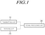
- FIG. 1is a block diagram to explain a radar signal processing apparatus, according to the present embodiment
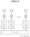
- FIG. 2is a view to explain a process of performing the beamforming
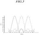
- FIG. 3is a view showing the basic beam
- FIG. 4is a flowchart illustrating a signal processing method of the radar signal processing apparatus, according to the present embodiment
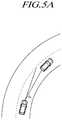
- FIGS. 5(A) and 5(B)is an exemplary view to explain the environment for performing the additional beamforming to match the target angle;
- FIGS. 6(A) and 6(B)is an exemplary view to explain the environment for performing the additional beamforming by adjusting the beam spread angle.
- FIGS. 7(A) and 7(B)is a graph showing the target signal and the clutter signal in the case where the clutter exists near the vehicle.
- FIG. 1is a block diagram to explain a radar signal processing apparatus, according to the present embodiment
- FIG. 2is a view to explain a process of performing the beamforming
- FIG. 3is a view showing the basic beam.
- the radar signal processing apparatusincludes: a transmitting unit 10 that transmits radar signals forward from the vehicle; a receiving unit 20 that receives signals that are reflected back among the transmitted radar signals; and a signal processing unit 30 that integrates the received signals and performs the beamforming for obtaining a desired gain in order to thereby extract the distance, speed, and azimuth with respect to a target.
- the receiving unit 20receives signals that are reflected back among the radar signals transmitted by the transmitting unit 10 by using an antenna array including a plurality of receiving antennas.
- the signal processing unit 30may: convert the signal received from a plurality of receiving antennas into a digital signal by means of an ADC (analog-digital converter); shift the phase of the received signal, which has been converted to the digital signal; and perform the digital beamforming in order to secure the gain that is obtained by summating the shifted phases.
- ADCanalog-digital converter
- Two or more beamformingsmay be performed, and one or more beamformings may be determined by configuring the target angle between the target and the travelling direction of the vehicle as the beam spread angle.
- the beamformingthat is performed by configuring the target angle between the target and the travelling direction of the vehicle as the beam spread angle.
- the signal processing unit 30determines whether or not there is a target in the formed beams (that is, the basic beam). If there is no target in the basic beam, the signal processing unit 30 determines the angle of a target that is positioned in front of the vehicle, and performs the additional beamforming to match the determined target angle. Alternatively, the signal processing unit 30 may perform the additional beamforming in which the target angle is configured as the beam spread angle regardless of the existence of the target in the basic beam.
- the target angle and the existence of the targetmay be estimated through track information (distance, speed, and angle information) of the vehicle, which results from the signal processing during the previous calculation cycle, because the detection by radar sensors including the transmitting unit 10 and the receiving unit 20 is made in real time.
- the trackis a final result of the signal processing for estimating the actual position of the target by using the target information that is measured while containing an error in the signal processing. Even if no target is detected due to the received signal being in a bad condition, the actual target position may be estimated in the tracking by using the track information of the previous cycle.
- the existence of the targetmeans the existence of a preceding vehicle.
- the basic beamis illustrated in FIG. 3 , and the basic beam may be comprised of three beams that are adjusted by a predetermined angle, respectively.
- the signal processing unit 30may extract and determine the target angle that is contained in the tracking information of the preceding target, or may determine the target angle according to the travelling direction of a vehicle.
- the signal processing unit 30detects the preceding target through the additional beamforming to match the determined target angle in order to thereby extract the distance, speed, and azimuth of the target. That is, a peak frequency, which is determined to be a target, is measured in a certain beam, and the signal processing unit 30 may extract the distance information (the distance, speed, and azimuth of the target) of the target by using signal information of the corresponding frequency.
- the signal processing unit 30may perform the additional beamforming by configuring one or more beam spread angles such that the received signal gain is maximized in the target angle.
- the extracted distance, speed, and azimuth of the targetmay be applied to the convenient devices for the driver (for example, an adaptive cruise control device) to enable autonomous travelling while stably maintaining the distance to the preceding vehicle.
- the convenient devices for the driverfor example, an adaptive cruise control device
- the signal processing unit 30calculates the gains of the target and the clutter, respectively, and performs the additional beamforming by adjusting the beam spread angle such that the calculated SCR (signal-to-clutter ratio) reaches a configured maximum reference ratio. That is, since the signal processing unit 30 adjusts the beam spread angle for an optimal SCR and then performs the additional beamforming, the target signal and the clutter signal can be separated so that the target can be easily extracted even if the clutter exists near the vehicle.
- the beam spread angle in the present specificationdenotes a reference angle for the beamforming, and may be referred to as various terms, such as a directional angle or a beam central angle, but the beam spread angle is not limited to a specific name.
- the signal processing unit 30may determine one or more beam spread angles for the additional beamforming by further using clutter angle information between the travelling direction and the clutter structure. For example, one or more beam spread angles for the additional beamforming may be determined such that the difference between the target gain by the target and the clutter gain by the clutter structure is maximized. As another example, one or more beam spread angles for the additional beamforming may be determined such that the ratio of the target gain by the target to the clutter gain by the clutter structure is minimized. As another example, one or more beam spread angles for the additional beamforming may be determined such that the ratio of the clutter gain by the clutter structure to the target gain by the target is maximized.
- the clutter structurewill be referred to as a clutter.
- the signal processing unit 30may determine the stationary target having an absolute speed of ‘0’ to be a clutter. Like the targets, since the clutters have angle information, if the stationary targets having an absolute speed of ‘0’ are consecutively arranged or form a specific group, the signal processing unit 30 may determine that the clutter is positioned at the corresponding angle through a variety of decision logic. Although the clutter is determined based on the speed information contained in the radar in the present embodiment, the existence of the clutter may be determined through surrounding images that are obtained from a camera.
- FIG. 4is a flowchart illustrating a signal processing method of the radar signal processing apparatus, according to the present embodiment.
- the signal processing unit 30receives, through a plurality of receiving antennas, signals that are reflected back among radar signals transmitted by the transmitting unit 10 , respectively (S 11 ).
- the signal processing unit 30integrates the received signals and performs the beamforming to obtain a desired gain (S 13 ). At this time, three basic beams are formed at a predetermined angle by the performed beamforming.
- the signal processing unit 30determines whether or not there is a target in the basic formed beams (S 15 ).
- the signal processing unit 30extracts the distance, speed, and azimuth of the target (S 23 ).
- the signal processing unit 30determines whether or not there is a clutter near the vehicle (S 17 ).
- the signal processing unit 30determines the angle of the target that is positioned in front of the vehicle (S 19 ). At this time, the target angle may be determined based on the tracking information of the preceding target, or may be determined based on the travelling direction of the vehicle.
- the signal processing unit 30performs the additional beamforming to match the determined target angle (S 21 ).
- the signal processing unit 30obtains the gains of the target and the clutter, respectively, and performs the additional beamforming by adjusting the beam spread angle such that the obtained gain ratio reaches a predetermined maximum reference ratio (S 22 ).
- the signal processing unit 30may apply the angle information of the target and the clutter to the X-axis of the beamforming gain graph in order to thereby obtain each gain in consideration of the gain for each angle.
- the beam spread angle of the beamformingchanges, the gains for the target angle and the clutter angle also change.
- the beam spread angle of the beamformingmay be obtained, in which such a ratio of the gains is maximized.
- the signal processing unit 30extracts the distance, angle, and azimuth of the target through the additional beamforming (S 23 ).
- the additional beamforming (VB)is performed to match the target angle ⁇ , in order to thereby improve the detection performance of the target.
- the target anglematches the beam spread angle ⁇ BF .
- the additional beamforming (VB)is performed with a beam spread angle ⁇ BF ′ in which the ratio of the target to the clutter (SCR) is maximized, as shown in diagram of FIG. 6(B) , in order to thereby improve the detection performance of the target.
- the beam spread angle ⁇ BF ′ according to the additional beamforming (VB)may be determined such that the difference between the gain of the target and the gain of the clutter is maximized.
- Diagram of FIG. 7(A)shows waveforms that are measured with respect to three basic beams in the travelling environment of diagram of FIG. 6(A)
- diagram of FIG. 7(B)shows waveforms that are measured when performing the additional beamforming by adjusting the beam spread angle such that the gain ratio of the target and the clutter is maximized in addition to the three basic beams.
- the beam spread angleis adjusted such that the SCR between the target signal (T) and the clutter signal (C) is maximized so that the target signal (T) and the clutter signal (C) can be clearly separated so that the target signal may be extracted, thereby easily extracting the distance, speed, and azimuth of the target.
- the embodiments described abovemay be applied to the case where the vehicles travel on a curved road. That is, when the vehicles travel on a curved road, the additional beamforming described above may be performed.
Landscapes
- Engineering & Computer Science (AREA)
- Radar, Positioning & Navigation (AREA)
- Remote Sensing (AREA)
- Physics & Mathematics (AREA)
- Computer Networks & Wireless Communication (AREA)
- General Physics & Mathematics (AREA)
- Electromagnetism (AREA)
- Radar Systems Or Details Thereof (AREA)
Abstract
Description
Claims (13)
Applications Claiming Priority (2)
| Application Number | Priority Date | Filing Date | Title |
|---|---|---|---|
| KR10-2015-0081233 | 2015-06-09 | ||
| KR1020150081233AKR102435550B1 (en) | 2015-06-09 | 2015-06-09 | Apparatur for processing signal of radar and method for processing signal thereof |
Publications (2)
| Publication Number | Publication Date |
|---|---|
| US20160363651A1 US20160363651A1 (en) | 2016-12-15 |
| US10613196B2true US10613196B2 (en) | 2020-04-07 |
Family
ID=57395676
Family Applications (1)
| Application Number | Title | Priority Date | Filing Date |
|---|---|---|---|
| US15/177,330Active2038-07-22US10613196B2 (en) | 2015-06-09 | 2016-06-08 | Apparatus for processing signals of radar and method for processing signals thereof |
Country Status (4)
| Country | Link |
|---|---|
| US (1) | US10613196B2 (en) |
| KR (1) | KR102435550B1 (en) |
| CN (1) | CN106249214B (en) |
| DE (1) | DE102016210043A1 (en) |
Cited By (1)
| Publication number | Priority date | Publication date | Assignee | Title |
|---|---|---|---|---|
| US20250035436A1 (en)* | 2023-07-27 | 2025-01-30 | Aptiv Technologies Limited | NLS Using a Bounded Linear Initial Search Space and a Fixed Grid with Pre-Calculated Variables |
Families Citing this family (21)
| Publication number | Priority date | Publication date | Assignee | Title |
|---|---|---|---|---|
| JP6516645B2 (en)* | 2015-09-30 | 2019-05-22 | 三菱電機株式会社 | Radar equipment |
| US10454553B2 (en)* | 2017-03-01 | 2019-10-22 | Samsung Electronics Co., Ltd. | Beam forming method for a transmitting antenna and a device thereof |
| US20190033439A1 (en)* | 2017-07-27 | 2019-01-31 | Richard Gu | Artificial intelligence enabled adaptive digital beam |
| CN108983176A (en)* | 2018-05-25 | 2018-12-11 | 中国人民解放军国防科技大学 | Radar Moving Target phase correction method based on reference array element |
| CN108983162A (en)* | 2018-05-25 | 2018-12-11 | 中国人民解放军国防科技大学 | Method for performing phase compensation on moving target by using phase compensation matrix |
| US10928507B2 (en)* | 2018-06-13 | 2021-02-23 | GM Global Technology Operations LLC | Apparatus and method for improved radar beamforming |
| DE102018210114A1 (en) | 2018-06-21 | 2019-12-24 | Robert Bosch Gmbh | Device and method for evaluating radar signals |
| DE102018210155A1 (en)* | 2018-06-21 | 2019-12-24 | Robert Bosch Gmbh | Method and device for evaluating radar signals |
| CN108845301B (en)* | 2018-08-17 | 2020-09-11 | 中国人民解放军陆军工程大学 | A Target Equivalent Rotation Center Estimation Method for Bistatic ISAR |
| KR20220004830A (en)* | 2019-06-03 | 2022-01-11 | 메타웨이브 코포레이션 | Guardband antenna of beam steering radar to improve resolution |
| KR102656900B1 (en)* | 2019-08-29 | 2024-04-11 | 에스케이텔레콤 주식회사 | Method for preventing signal interference of vehicle supporting c-v2x communication and wave communication and vehicle-mounted device performing method |
| CN113033586B (en)* | 2019-12-24 | 2024-04-16 | 大富科技(安徽)股份有限公司 | Target identification method and device |
| US11614514B2 (en)* | 2020-03-27 | 2023-03-28 | Intel Corporation | Apparatus, system and method of generating radar perception data |
| WO2022104666A1 (en)* | 2020-11-19 | 2022-05-27 | 深圳市大疆创新科技有限公司 | Radar system, movable platform, control method, obstacle avoidance method, and storage medium |
| KR102687407B1 (en)* | 2021-02-19 | 2024-07-23 | 주식회사 에이치엘클레무브 | Radar control apparatus and method |
| US11879968B2 (en)* | 2021-03-30 | 2024-01-23 | Texas Instruments Incorporated | Simultaneous beamforming and multiple input-multiple output (MIMO) schemes in radar system |
| CN113985358B (en)* | 2021-09-14 | 2024-08-02 | 西安电子科技大学 | Phased array MIMO-based receiving ADBF processing method |
| CN113537411B (en)* | 2021-09-15 | 2021-11-23 | 湖北工业大学 | Improved fuzzy clustering method based on millimeter wave radar |
| EP4220223A1 (en)* | 2022-01-26 | 2023-08-02 | Aptiv Technologies Limited | Radar device |
| KR102686717B1 (en)* | 2022-02-22 | 2024-07-19 | 주식회사 에이치엘클레무브 | Radar control apparatus and method |
| CN114415123B (en)* | 2022-04-01 | 2022-07-19 | 北京海兰信数据科技股份有限公司 | Non-coherent neighborhood based weighting pulse accumulation processing method and system |
Citations (12)
| Publication number | Priority date | Publication date | Assignee | Title |
|---|---|---|---|---|
| US4077038A (en)* | 1976-04-01 | 1978-02-28 | Westinghouse Electric Corporation | Digital radar control system and method |
| US5249157A (en)* | 1990-08-22 | 1993-09-28 | Kollmorgen Corporation | Collision avoidance system |
| US5280457A (en)* | 1992-07-31 | 1994-01-18 | The Administrators Of The Tulane Educational Fund | Position detecting system and method |
| US20030142007A1 (en)* | 2001-03-15 | 2003-07-31 | Daisaku Ono | Signal processing method for scanning radar |
| US20050024257A1 (en)* | 2003-07-28 | 2005-02-03 | Michael Britton | Object detection apparatus and method |
| US20060284757A1 (en)* | 2004-09-14 | 2006-12-21 | Zemany Paul D | Through-the-wall frequency stepped imaging system utilizing near field multiple antenna positions, clutter rejection and corrections for frequency dependent wall effects |
| KR100750967B1 (en) | 2006-05-02 | 2007-08-22 | 한국전기연구원 | Near-field high resolution vehicle radar system based on virtual array antenna system |
| US20090102717A1 (en)* | 2007-10-19 | 2009-04-23 | Raytheon Company | Sidelobe blanking characterizer system and method |
| US7623062B2 (en)* | 2006-08-01 | 2009-11-24 | Autoliv Asp, Inc. | System and method for target detection with a radar antenna |
| US20110187584A1 (en)* | 2010-01-29 | 2011-08-04 | Man-On Pun | Method for Suppressing Clutter in Space-Time Adaptive Processing Systems |
| US20120235857A1 (en)* | 2011-03-16 | 2012-09-20 | Electronics And Telecommunications Research Institute | Radar apparatus supporting short and long range radar operation |
| US8314732B2 (en)* | 2007-01-31 | 2012-11-20 | Cambridge Consultants Ltd. | Adaptive radar |
Family Cites Families (10)
| Publication number | Priority date | Publication date | Assignee | Title |
|---|---|---|---|---|
| JP3653862B2 (en)* | 1996-04-22 | 2005-06-02 | 日産自動車株式会社 | Vehicle curve diameter estimation device and target preceding vehicle detection device |
| JP3420955B2 (en)* | 1998-12-17 | 2003-06-30 | 富士通テン株式会社 | Beam scanning method for on-board scanning radar |
| DE102004059915A1 (en)* | 2004-12-13 | 2006-06-14 | Robert Bosch Gmbh | radar system |
| JP2007333486A (en)* | 2006-06-13 | 2007-12-27 | Denso Corp | Obstacle detector for vehicle |
| CN101520507B (en)* | 2007-07-20 | 2012-03-21 | 通用汽车环球科技运作公司 | Ow cost short range radar |
| JP5091651B2 (en)* | 2007-12-14 | 2012-12-05 | 日立オートモティブシステムズ株式会社 | Radar apparatus and target azimuth measurement method |
| JP2010071865A (en)* | 2008-09-19 | 2010-04-02 | Fujitsu Ten Ltd | Signal processing device and radar device |
| EP2372835A4 (en)* | 2008-11-28 | 2015-06-17 | Hitachi Chemical Co Ltd | MULTI-BEAM ANTENNA DEVICE |
| KR101286873B1 (en)* | 2009-01-29 | 2013-07-16 | 히타치가세이가부시끼가이샤 | Multi-beam antenna apparatus |
| KR101938898B1 (en)* | 2013-06-27 | 2019-04-10 | 주식회사 만도 | Method and device for detecting a beam of radar array antenna |
- 2015
- 2015-06-09KRKR1020150081233Apatent/KR102435550B1/enactiveActive
- 2016
- 2016-06-07DEDE102016210043.2Apatent/DE102016210043A1/enactivePending
- 2016-06-08CNCN201610405005.1Apatent/CN106249214B/enactiveActive
- 2016-06-08USUS15/177,330patent/US10613196B2/enactiveActive
Patent Citations (12)
| Publication number | Priority date | Publication date | Assignee | Title |
|---|---|---|---|---|
| US4077038A (en)* | 1976-04-01 | 1978-02-28 | Westinghouse Electric Corporation | Digital radar control system and method |
| US5249157A (en)* | 1990-08-22 | 1993-09-28 | Kollmorgen Corporation | Collision avoidance system |
| US5280457A (en)* | 1992-07-31 | 1994-01-18 | The Administrators Of The Tulane Educational Fund | Position detecting system and method |
| US20030142007A1 (en)* | 2001-03-15 | 2003-07-31 | Daisaku Ono | Signal processing method for scanning radar |
| US20050024257A1 (en)* | 2003-07-28 | 2005-02-03 | Michael Britton | Object detection apparatus and method |
| US20060284757A1 (en)* | 2004-09-14 | 2006-12-21 | Zemany Paul D | Through-the-wall frequency stepped imaging system utilizing near field multiple antenna positions, clutter rejection and corrections for frequency dependent wall effects |
| KR100750967B1 (en) | 2006-05-02 | 2007-08-22 | 한국전기연구원 | Near-field high resolution vehicle radar system based on virtual array antenna system |
| US7623062B2 (en)* | 2006-08-01 | 2009-11-24 | Autoliv Asp, Inc. | System and method for target detection with a radar antenna |
| US8314732B2 (en)* | 2007-01-31 | 2012-11-20 | Cambridge Consultants Ltd. | Adaptive radar |
| US20090102717A1 (en)* | 2007-10-19 | 2009-04-23 | Raytheon Company | Sidelobe blanking characterizer system and method |
| US20110187584A1 (en)* | 2010-01-29 | 2011-08-04 | Man-On Pun | Method for Suppressing Clutter in Space-Time Adaptive Processing Systems |
| US20120235857A1 (en)* | 2011-03-16 | 2012-09-20 | Electronics And Telecommunications Research Institute | Radar apparatus supporting short and long range radar operation |
Cited By (1)
| Publication number | Priority date | Publication date | Assignee | Title |
|---|---|---|---|---|
| US20250035436A1 (en)* | 2023-07-27 | 2025-01-30 | Aptiv Technologies Limited | NLS Using a Bounded Linear Initial Search Space and a Fixed Grid with Pre-Calculated Variables |
Also Published As
| Publication number | Publication date |
|---|---|
| DE102016210043A1 (en) | 2016-12-15 |
| US20160363651A1 (en) | 2016-12-15 |
| CN106249214A (en) | 2016-12-21 |
| KR20160144729A (en) | 2016-12-19 |
| KR102435550B1 (en) | 2022-08-24 |
| CN106249214B (en) | 2019-02-19 |
Similar Documents
| Publication | Publication Date | Title |
|---|---|---|
| US10613196B2 (en) | Apparatus for processing signals of radar and method for processing signals thereof | |
| KR102401176B1 (en) | Radar image processing method, apparatus and system | |
| KR102516365B1 (en) | Method and apparatus for controlling radar of vehicle | |
| US10126409B2 (en) | Method and MIMO radar device for determining a position angle of an object | |
| US9746554B2 (en) | Radar imaging system and related techniques | |
| US9134409B2 (en) | Vehicle-mounted radar apparatus | |
| CN109477892B (en) | Vehicle radar for environmental detection | |
| KR20200067629A (en) | Method and device to process radar data | |
| US20140022109A1 (en) | Radar field of view expansion with phased array transceiver | |
| CN105393135A (en) | Determination of an elevation misalignment angle of a radar sensor of a motor vehicle | |
| WO2018035148A1 (en) | Novel automotive radar using 3d printed luneburg lens | |
| KR102516367B1 (en) | Method and device to process radar data | |
| JP2019518946A (en) | Radar sensor device for a motor vehicle, driver assistance system, motor vehicle and method for sensing an object | |
| US11180137B2 (en) | Vehicle environmental detection system for parking detection | |
| CN113625280B (en) | Vehicle radar device, radar device control method, and vehicle radar system | |
| CN113625279B (en) | Device and method for detecting vertical installation misalignment of radar device and radar device having the same | |
| US11614535B2 (en) | Radar apparatus for vehicle and method for controlling the same | |
| JP4754856B2 (en) | Automotive radar equipment | |
| CN111712722A (en) | Estimate the lateral or Cartesian velocity of a point target with the aid of a radar sensor | |
| KR20210152911A (en) | Method and apparatus of processing radar signal by correcting phase distortion | |
| CN110658390A (en) | Method for determining alignment errors of an antenna and a vehicle using an antenna and a detection device | |
| JP2010181182A (en) | Onboard radar device, and target recognition method | |
| KR101938898B1 (en) | Method and device for detecting a beam of radar array antenna | |
| US11333754B2 (en) | Detection of parking row orientation | |
| KR20140088683A (en) | Apparatus, method and computer readable recording medium for detecting an object using an automotive radar |
Legal Events
| Date | Code | Title | Description |
|---|---|---|---|
| AS | Assignment | Owner name:MANDO CORPORATION, KOREA, REPUBLIC OF Free format text:ASSIGNMENT OF ASSIGNORS INTEREST;ASSIGNOR:LIM, HAESUENG;REEL/FRAME:038851/0313 Effective date:20160608 | |
| STPP | Information on status: patent application and granting procedure in general | Free format text:NON FINAL ACTION MAILED | |
| STPP | Information on status: patent application and granting procedure in general | Free format text:RESPONSE TO NON-FINAL OFFICE ACTION ENTERED AND FORWARDED TO EXAMINER | |
| STPP | Information on status: patent application and granting procedure in general | Free format text:FINAL REJECTION MAILED | |
| STPP | Information on status: patent application and granting procedure in general | Free format text:RESPONSE AFTER FINAL ACTION FORWARDED TO EXAMINER | |
| STPP | Information on status: patent application and granting procedure in general | Free format text:ADVISORY ACTION MAILED | |
| STPP | Information on status: patent application and granting procedure in general | Free format text:DOCKETED NEW CASE - READY FOR EXAMINATION | |
| STPP | Information on status: patent application and granting procedure in general | Free format text:NOTICE OF ALLOWANCE MAILED -- APPLICATION RECEIVED IN OFFICE OF PUBLICATIONS | |
| STPP | Information on status: patent application and granting procedure in general | Free format text:PUBLICATIONS -- ISSUE FEE PAYMENT RECEIVED | |
| STCF | Information on status: patent grant | Free format text:PATENTED CASE | |
| AS | Assignment | Owner name:MANDO MOBILITY SOLUTIONS CORPORATION, KOREA, REPUBLIC OF Free format text:ASSIGNMENT OF ASSIGNORS INTEREST;ASSIGNOR:MANDO CORPORATION;REEL/FRAME:058214/0306 Effective date:20211026 | |
| AS | Assignment | Owner name:HL KLEMOVE CORP., KOREA, REPUBLIC OF Free format text:MERGER;ASSIGNOR:MANDO MOBILITY SOLUTIONS CORPORATION;REEL/FRAME:060841/0955 Effective date:20211202 | |
| AS | Assignment | Owner name:HL MANDO CORPORATION, KOREA, REPUBLIC OF Free format text:CHANGE OF NAME;ASSIGNOR:MANDO CORPORATION;REEL/FRAME:062152/0127 Effective date:20220905 | |
| MAFP | Maintenance fee payment | Free format text:PAYMENT OF MAINTENANCE FEE, 4TH YEAR, LARGE ENTITY (ORIGINAL EVENT CODE: M1551); ENTITY STATUS OF PATENT OWNER: LARGE ENTITY Year of fee payment:4 |