US10612752B2 - Downwardly directing spatial lighting system - Google Patents
Downwardly directing spatial lighting systemDownload PDFInfo
- Publication number
- US10612752B2 US10612752B2US15/922,316US201815922316AUS10612752B2US 10612752 B2US10612752 B2US 10612752B2US 201815922316 AUS201815922316 AUS 201815922316AUS 10612752 B2US10612752 B2US 10612752B2
- Authority
- US
- United States
- Prior art keywords
- light
- lenses
- diffuser
- distribution pattern
- light intensity
- Prior art date
- Legal status (The legal status is an assumption and is not a legal conclusion. Google has not performed a legal analysis and makes no representation as to the accuracy of the status listed.)
- Expired - Fee Related
Links
- 238000000034methodMethods0.000claimsabstractdescription28
- 239000011248coating agentSubstances0.000claimsabstractdescription5
- 238000000576coating methodMethods0.000claimsabstractdescription5
- 239000000463materialSubstances0.000claimsdescription7
- 230000004313glareEffects0.000description12
- 230000000694effectsEffects0.000description6
- 238000005286illuminationMethods0.000description5
- 239000004033plasticSubstances0.000description3
- 230000004438eyesightEffects0.000description2
- 239000002184metalSubstances0.000description2
- 239000004065semiconductorSubstances0.000description2
- 239000002253acidSubstances0.000description1
- NIXOWILDQLNWCW-UHFFFAOYSA-Nacrylic acid groupChemical groupC(C=C)(=O)ONIXOWILDQLNWCW-UHFFFAOYSA-N0.000description1
- 239000011521glassSubstances0.000description1
- 238000001746injection mouldingMethods0.000description1
- 238000012423maintenanceMethods0.000description1
- 239000004417polycarbonateSubstances0.000description1
- 229920000515polycarbonatePolymers0.000description1
- 238000002310reflectometryMethods0.000description1
Images


Classifications
- F—MECHANICAL ENGINEERING; LIGHTING; HEATING; WEAPONS; BLASTING
- F21—LIGHTING
- F21V—FUNCTIONAL FEATURES OR DETAILS OF LIGHTING DEVICES OR SYSTEMS THEREOF; STRUCTURAL COMBINATIONS OF LIGHTING DEVICES WITH OTHER ARTICLES, NOT OTHERWISE PROVIDED FOR
- F21V13/00—Producing particular characteristics or distribution of the light emitted by means of a combination of elements specified in two or more of main groups F21V1/00 - F21V11/00
- F21V13/02—Combinations of only two kinds of elements
- F21V13/04—Combinations of only two kinds of elements the elements being reflectors and refractors
- F—MECHANICAL ENGINEERING; LIGHTING; HEATING; WEAPONS; BLASTING
- F21—LIGHTING
- F21S—NON-PORTABLE LIGHTING DEVICES; SYSTEMS THEREOF; VEHICLE LIGHTING DEVICES SPECIALLY ADAPTED FOR VEHICLE EXTERIORS
- F21S8/00—Lighting devices intended for fixed installation
- F21S8/08—Lighting devices intended for fixed installation with a standard
- F21S8/085—Lighting devices intended for fixed installation with a standard of high-built type, e.g. street light
- F21S8/086—Lighting devices intended for fixed installation with a standard of high-built type, e.g. street light with lighting device attached sideways of the standard, e.g. for roads and highways
- F—MECHANICAL ENGINEERING; LIGHTING; HEATING; WEAPONS; BLASTING
- F21—LIGHTING
- F21V—FUNCTIONAL FEATURES OR DETAILS OF LIGHTING DEVICES OR SYSTEMS THEREOF; STRUCTURAL COMBINATIONS OF LIGHTING DEVICES WITH OTHER ARTICLES, NOT OTHERWISE PROVIDED FOR
- F21V5/00—Refractors for light sources
- F21V5/007—Array of lenses or refractors for a cluster of light sources, e.g. for arrangement of multiple light sources in one plane
- F—MECHANICAL ENGINEERING; LIGHTING; HEATING; WEAPONS; BLASTING
- F21—LIGHTING
- F21V—FUNCTIONAL FEATURES OR DETAILS OF LIGHTING DEVICES OR SYSTEMS THEREOF; STRUCTURAL COMBINATIONS OF LIGHTING DEVICES WITH OTHER ARTICLES, NOT OTHERWISE PROVIDED FOR
- F21V5/00—Refractors for light sources
- F21V5/08—Refractors for light sources producing an asymmetric light distribution
- F—MECHANICAL ENGINEERING; LIGHTING; HEATING; WEAPONS; BLASTING
- F21—LIGHTING
- F21V—FUNCTIONAL FEATURES OR DETAILS OF LIGHTING DEVICES OR SYSTEMS THEREOF; STRUCTURAL COMBINATIONS OF LIGHTING DEVICES WITH OTHER ARTICLES, NOT OTHERWISE PROVIDED FOR
- F21V7/00—Reflectors for light sources
- F21V7/22—Reflectors for light sources characterised by materials, surface treatments or coatings, e.g. dichroic reflectors
- F21V7/28—Reflectors for light sources characterised by materials, surface treatments or coatings, e.g. dichroic reflectors characterised by coatings
- F—MECHANICAL ENGINEERING; LIGHTING; HEATING; WEAPONS; BLASTING
- F21—LIGHTING
- F21V—FUNCTIONAL FEATURES OR DETAILS OF LIGHTING DEVICES OR SYSTEMS THEREOF; STRUCTURAL COMBINATIONS OF LIGHTING DEVICES WITH OTHER ARTICLES, NOT OTHERWISE PROVIDED FOR
- F21V3/00—Globes; Bowls; Cover glasses
- F—MECHANICAL ENGINEERING; LIGHTING; HEATING; WEAPONS; BLASTING
- F21—LIGHTING
- F21W—INDEXING SCHEME ASSOCIATED WITH SUBCLASSES F21K, F21L, F21S and F21V, RELATING TO USES OR APPLICATIONS OF LIGHTING DEVICES OR SYSTEMS
- F21W2131/00—Use or application of lighting devices or systems not provided for in codes F21W2102/00-F21W2121/00
- F21W2131/10—Outdoor lighting
- F21W2131/103—Outdoor lighting of streets or roads
- F—MECHANICAL ENGINEERING; LIGHTING; HEATING; WEAPONS; BLASTING
- F21—LIGHTING
- F21Y—INDEXING SCHEME ASSOCIATED WITH SUBCLASSES F21K, F21L, F21S and F21V, RELATING TO THE FORM OR THE KIND OF THE LIGHT SOURCES OR OF THE COLOUR OF THE LIGHT EMITTED
- F21Y2105/00—Planar light sources
- F21Y2105/10—Planar light sources comprising a two-dimensional array of point-like light-generating elements
- F—MECHANICAL ENGINEERING; LIGHTING; HEATING; WEAPONS; BLASTING
- F21—LIGHTING
- F21Y—INDEXING SCHEME ASSOCIATED WITH SUBCLASSES F21K, F21L, F21S and F21V, RELATING TO THE FORM OR THE KIND OF THE LIGHT SOURCES OR OF THE COLOUR OF THE LIGHT EMITTED
- F21Y2115/00—Light-generating elements of semiconductor light sources
- F21Y2115/10—Light-emitting diodes [LED]
Definitions
- the present disclosurerelates generally to lighting systems and, more particularly, to outdoor lighting systems incorporating a light diffuser to reduce glare.
- LEDlight emitting diode
- An ideal design of an LED lighting systemprovides sufficient illumination levels on the ground while creating the effect of minimal light at the LED.
- many LED manufacturersplace a primary optic or lens over the semi-conductor element of the LED to create a lambertian light distribution pattern. While this light distribution pattern reduces glare to some degree, some applications, such as roadway lighting, require an even greater amount of glare reduction.
- a secondary optic or lensis placed over each of the LEDs to further distribute the light. Adding the secondary optic, as opposed to modifying the primary optic itself, is preferred because the primary optic is typically installed by the manufacturer and closely integrated with the semi-conductor element of the LED.
- the secondary optictypically employs a bubble refraction design that creates a batwing-shaped light distribution pattern in which light rays of greatest intensity extend from a central axis of the secondary optic at a relatively high angle. These high angle light rays, while effective at more evenly illuminating the ground surfaces beneath the luminaire, nevertheless create a significant glare for an individual approaching the luminaire.
- a tertiary optic or lensis added to diffuse the directional light emitted from the secondary optic.
- the diffusing characteristic of the tertiary opticdisperses light over a larger surface area and thus reduces glare.
- Known tertiary opticsare substantially curved and cover the entire array of the LEDs. As light rays pass through the curved upper ends of the tertiary optic, the light rays are diffracted in the horizontal and upward directions. This results in an undesirable light distribution if the luminaire is to be used outdoors, for example, to illuminate a parking lot or road.
- outdoor luminariesdo not emit light in the upward direction because such light tends to exacerbate the problem of light pollution (i.e., the haze of wasted light that envelops many large cities and towns). If the luminaire is configured as a parking lot lamp or street lamp, emitting light in the horizontal direction is also undesirable because doing so may illuminate adjoining properties instead of the intended parking lot surface or road.
- Pixilation castsshows that can change the look of an illuminated object and potentially create optical illusions.
- One aspect of the present disclosureincludes a luminaire that includes a plurality of LEDs disposed on a mount surface.
- the luminairefurther includes a light diffuser spaced apart from the plurality of LEDs and including a planar surface facing the plurality of LEDs.
- the luminairefurther includes a reflector surrounding a cavity formed between the light diffuser and the plurality of LEDs.
- the plurality of LEDsmay emit light away from the mount surface toward the planar surface of the light diffuser, whereat a first portion of the emitted light transmits through the light diffuser and a second portion reflects off of the planar surface of the light diffuser to the reflector.
- the methodincludes emitting light from a first light source towards a planar surface of a light diffuser in a first light distribution pattern such that the emitted light is directly incident upon the planar surface. Additionally, the method includes emitting light from a second light source towards the planar surface of the light diffuser in a second light distribution pattern different than the first light distribution pattern such that the emitted light is directly incident upon the planar surface.
- the planar surfacemay have a reflective material coating, such that the emitted light from the first light source and second light source that is directly incident upon the planar surface is directly incident upon the reflective material coating of the planar surface.
- the methodadditionally includes scattering a first portion of the light from the first light source and the second light source with the light diffuser, and reflecting a second portion of the light from the first light source and the second light source with the light diffuser. Still additionally, the method includes reflecting the second portion of the light from the first light source and the second light source with a first reflective surface back towards the light diffuser. Furthermore, the method includes scattering the second portion of the light from the first light source and the second light source with the light diffuser.
- a further aspect of the present disclosureinvolves another method of distributing light.
- the methodincludes emitting light from a plurality of light sources toward a plurality of lenses, each of the light sources being aligned with a respective one of the plurality of lenses. Additionally, the method converting a first portion of the emitted light into a first light intensity distribution pattern via a first portion of the plurality of lenses, the first light intensity distribution pattern directed toward a light diffuser spaced apart from the plurality of lenses.
- the methodincludes converting a second portion of the emitted light into a second light intensity distribution pattern via a second portion of the plurality of lenses, the light intensity distribution pattern comprising a first bundle of light rays directed toward the light diffuser and a second bundle of light rays directed toward a reflector surrounding a cavity formed between the light diffuser and the plurality of lenses. Still additionally, the method includes reflecting the light from the second bundle with the reflector, the reflected light from the second bundle reflected toward the light diffuser.
- the methodincludes scattering, with the light diffuser, at least a portion of each of (i) the light from the first light intensity distribution pattern, (ii) the light from the first bundle of light rays from the second light intensity distribution pattern, and (iii) the reflected light rays from the second bundle of light rays from the second light intensity distribution pattern.
- FIG. 1is perspective view of one embodiment of a luminaire of the present disclosure
- FIG. 2depicts a cross-sectional view of the luminaire of FIG. 1 ;
- FIG. 3is a bottom view of the luminaire of FIG. 1 with the light diffuser removed;
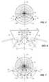
- FIG. 4illustrates a cross-sectional view of one of the plurality of secondary lenses associated with the inner cluster of LEDs
- FIG. 5is a polar distribution graph of the light distribution pattern created by the secondary lens of FIG. 4 ;
- FIG. 6is a cross-sectional view of one of the plurality of secondary lenses associated with the outer cluster of LEDs
- FIG. 7is a polar distribution of the light distribution pattern created by the secondary lens of FIG. 6 ;
- FIG. 8is a cross-sectional view of one side of the luminaire of FIG. 1 with one of the LEDs of the inner cluster turned ON;
- FIG. 9is a cross-sectional view of one side of the luminaire of FIG. 1 with one of the LEDs of the outer cluster turned ON.
- FIGS. 1-3illustrate a luminaire 10 including a housing 12 enclosing a plurality of light sources, which in the present embodiment are configured as light emitting diodes (LEDs) 14 .
- LEDslight emitting diodes
- Other embodimentsmay use different types of light sources including, but not limited to, incandescent, fluorescent, and/or high-intensity discharge bulbs.
- the LEDsare arranged in an array 16 that is mounted to the interior of the housing 12 .
- Each of the LEDs 14is packaged with an integral primary optic or lens (not shown) that provides a lambertian light distribution.
- the array 16includes a plurality of secondary optics or lenses 18 a , 18 b , each of which covers a respective one of the LEDs 14 and distributes light in a batwing-shaped distribution pattern.
- the LEDs 14are divided into an inner cluster 20 and an outer cluster 22 , with the outer cluster 22 being arranged around the periphery of the inner cluster 20 .
- the secondary lenses 18 awhich are aligned with the inner cluster 20 of the LEDs 14 , create a light distribution pattern that differs from the secondary lenses 18 b , which are aligned with the outer cluster 22 of the LEDs 14 .
- the light rays emitted by the LEDs 14strike a tertiary optic or lens, which in the present embodiment is configured as a light diffuser 24 , which covers an open end of the housing 12 .
- the light diffuser 24includes a substantially planar upper surface that reflects a portion of the incident light back into the housing 12 and transmits a portion of the incident light downward toward the ground.
- the transmitted portion of the lightis scattered or spread out by the light diffuser 24 and thereby results in the emission of relatively soft light.
- the reflected portion of the lightbounces off a reflector 28 arranged inside the housing 12 and thereafter strikes the light diffuser 24 at a more optimal angle, causing the light to exit the luminaire 10 in a more focused and intended direction.
- the luminaire 10 of the present disclosureadvantageously provides sufficient illumination at the ground level while creating the effect of minimal light at the luminaire 10 .
- the luminaire 10thus minimizes the glare perceived by an individual looking at the luminaire 10 .
- the generally planar upper surface of the light diffuser 24helps evenly distribute the light and thus reduces the effects of pixilation.
- the reflector 28redirects high angle light rays at a more optimal angle so that the light rays exit the luminaire 10 in a generally downward direction. Accordingly, the luminaire 10 prevents the emission of upwardly directed light rays, which tend to cause light pollution, and also prevents light rays from exiting the sides of the luminaire 10 and illuminating objects outside an intended zone of illumination.
- the luminaire 10is suitable for outdoor use, for example, as a parking lot lamp and/or a street lamp.
- the housing 12may be constructed from a durable plastic and/or metal capable of withstanding weather elements such as rain, snow, ice, etc.
- An arm-like structure 30which extends from the side of the housing 12 , may be used to cantilever the housing from the top of a light pole (not shown).
- the housing 12is arranged approximately (e.g., ⁇ 10%) 15-30 feet above the ground.
- the housing 12may be pivotally attached to the arm-like structure 30 so that the housing 12 can be easily opened to replace the LEDs 14 or to perform other maintenance-related tasks. As illustrated in FIG.
- the housing 12possesses a hollow interior 31 containing the LEDs 14 , the reflector 28 , mounting structures (not shown), a power source interface (not shown), and control electronics (also not shown).
- the light diffuser 24extends across the open end of the housing 12 so that all light exiting the luminaire 10 passes through the light diffuser 24 .
- FIG. 3depicts a bottom view of the luminaire 10 with the light diffuser 24 removed so that the array 16 of the LEDs 14 is visible.
- the array 16 shown in FIG. 3includes 52 individual LEDs 14 arranged in a generally hexagonal pattern. Other embodiments can be arranged differently, for example, with a different number of LEDs arranged in circular pattern. In one preferred form, the luminaire 10 can have 96 LEDs.
- the outer cluster 22 of the LEDs 14 shown in FIG. 3is formed by the radially outermost row of the LEDs. In other embodiments, the outer cluster 22 may be formed, for example, by several (e.g., 2, 3, 4, 5, 6, etc.) outer rows of the LEDs 14 .
- the array 16 carrying the LEDs 14is removably attached to a planar downwardly facing reflective surface 32 of the reflector 28 by screws 35 ( FIGS. 8 and 9 ) or other suitable fasteners.
- the array 16has a smaller diameter than the downwardly facing reflecting surface 32 of the reflector 28 so that a portion of the downwardly facing reflecting surface 32 of the reflector 28 is not covered by the array 16 .
- the reflector 28includes a circumferential reflective surface 34 that surrounds a gap or cavity 33 formed between the LEDs 16 and the light diffuser 24 .
- the circumferential reflective surface 34is flat (in a cross-sectional view) and intersects the downwardly facing reflective surface 32 at a relatively abrupt angle. In other embodiments, the circumferential reflective surface 34 gradually bends into the downwardly facing reflective surface 32 such that the surfaces form a continuous parabolic or hemispherical shape, or some other curved shape.
- the circumferential reflective surface 34 and the downwardly facing reflective surface 32are preferably made from metal, plastic or other material having reflective properties.
- the light diffuser 24includes an upwardly facing surface 36 spaced apart from and facing the LEDs 14 .
- the upwardly facing surface 36is offset from the LEDs 14 by a distance of approximately (e.g., ⁇ 10%) 2-3 inches, or lesser or greater.
- the present embodiment of the upwardly facing surface 36is generally planar and orthogonal to a central axis A 1 of the luminaire 10 .
- the planar aspect of the upwardly facing surface 36coupled with the gap separating the upwardly facing surface 36 and the LEDs 14 , helps prevent pixilation of the light passing through the light diffuser 24 .
- the upwardly facing surface 36reflects a portion of the light rays back up into the luminaire 10 .
- the upwardly facing surface 36reflects approximately (e.g., ⁇ 10%) 20% of the incident light and transmits about (e.g., ⁇ 10%) 80% of the incident light. While there may be some energy losses associated with the reflection, it is generally desirable to reflect the light back up into the luminaire so that the reflector 28 can re-direct the light rays at a more optimal angle, and in a different location, so as to minimize pixilation.
- the reflection of high angle light raysalso helps control the size of the illuminated ground area by limiting the number of light rays that exit the luminaire 10 in the horizontal, or substantially horizontal, direction.
- the upwardly facing surface 36 of the light diffuser 24can be made from a variety of semi-transparent and/or semi-reflective surfaces such as plastic (e.g., acrylic or polycarbonate) or glass. Additionally, the upwardly facing surface 36 may be coated with a material that increases its reflectivity. In some embodiments, the light diffuser 24 is made of material that does not polarize the light.
- a downwardly facing surface 38 of the light diffuser 24is textured so that it scatters the light rays exiting the light diffuser 24 .
- the texturecan be formed by a mold having a mild acid etch that is used in an injection molding process to create the light diffuser 24 .
- the scattering effect of the downwardly facing surface 38substantially reduces glare, and also, creates the effect of a uniformly luminous surface, which is generally considered more aesthetically pleasing than the distinct points of light created by the LEDs 14 .
- each of the secondary lenses 18 a , 18 btransforms the light emitted from one of the LEDs 14 into a batwing-shaped light distribution pattern.
- a batwing-shaped light distribution patternpossesses at least one peak of light intensity arranged along a conical plane centered about a central axis of the lens.
- the secondary lenses 18 a associated with the inner cluster 20 of LEDscreate a batwing-shaped light distribution pattern that differs from the one created by the secondary lenses 18 b associated with the outer cluster 20 of LEDs.
- FIG. 4illustrates a cross-sectional view of one example of how the secondary lenses 18 a associated with one of the LEDs 14 of the inner cluster 20 could be structured.
- the center of the secondary lens 18 aincludes a cone-shaped cutout having a central surface 40 .
- a bundle of light rays 42 emitted from the LED 14are internally reflected by the central surface 40 and thereafter strike and refract through an outer surface 44 of the secondary lens 18 a .
- Each of the light rays 42exits the secondary lens 18 a at an angle relative to a central axis A 2 of the secondary lens 18 a measuring approximately (e.g., ⁇ 10%) 45-75 degrees, and within the range of 55-65 degrees.
- FIG. 4depicts an angle ⁇ 1 which represents an average angle of the light rays 42 emitted from the secondary lens 18 a .
- the lens depicted in FIG. 4is merely an example, and other lenses can be used to create a similar light distribution.
- FIG. 5depicts a polar distribution graph of the batwing-shaped light distribution pattern 50 created by the light emitted from the secondary lens 18 a illustrated in FIG. 4 .
- the batwing-shaped light distribution pattern 50if viewed in three dimensions, would extend symmetrically around the central axis A 2 of the secondary lens 18 a .
- the light distribution pattern 50has a peak of light intensity 52 arranged along an imaginary conical plane P 1 centered about the central axis A 2 of the secondary lens 18 a .
- the angle at which the peak of light intensity 52 extends away from the central axis A 2 of the secondary lens 18 ais generally equal to the angle 81 .
- FIG. 6illustrates a cross-sectional view of one example of how the secondary lenses 18 b associated with one of the LEDs 14 of the outer cluster 22 could be structured.
- the center of the secondary lens 18 bincludes a cone-shaped cutout having a central surface 60 .
- a first bundle of light rays 62 emitted from the LED 14are internally reflected by the central surface 60 and subsequently strike and refract through a lower outer surface 64 of the secondary lens 18 b .
- a second bundle of light rays 66 emitted from the LED 14are internally reflected by the central surface 60 and thereafter strike and refract through an upper outer surface 68 of the secondary lens 18 b .
- Each of the light rays 62 exiting the lower outer surface 64forms an angle with a central axis A 3 of the secondary lens 18 b of about (e.g., ⁇ 10%) 15-45 degrees, and within the range of 30-40 degrees.
- Each of the light rays 66 exiting the upper outer surface 68forms an angle with the central axis A 3 of approximately (e.g., ⁇ 10%) 65-85 degrees, preferably within the range of 70-80 degrees.
- an angle between the lower and upper outer surfaces 64 , 69can be in a range of about (e.g., ⁇ 10%) 100-155 degrees, or less or greater.
- FIG. 6depicts an angle ⁇ 2 which represents an average angle of the light rays 62 emitted from the lower outer surface 64 , and illustrates an angle 83 which represents an average angle of the light rays 66 emitted from the upper outer surface 68 .
- the central axis A 3 of the secondary lens 18 bis parallel to the central axis A 2 of the secondary lens 18 a and/or parallel to the central axis A 1 of the luminaire 10 .
- the lens of FIG. 6is merely an example and other lenses can be used to create a similar distribution.
- a gapis formed between the first and second bundles of lights rays 62 and 66 as they exit the secondary lens 18 b .
- the light distribution pattern 70possesses three peaks of light intensity 72 , 74 , 76 , each of which is arranged along a respective imaginary conical plane P 2 , P 3 , P 4 centered about the central axis A 3 of the secondary lens 18 b .
- the angle at which the first peak of light intensity 72 extends away from the central axis A 3is generally equal to the angle ⁇ 2
- the angle at which the second peak of light intensity 74 extends away from the central axis A 3is generally equal to the angle ⁇ 3
- the third peak of light intensity 76is less than both the first and second peaks of light intensity 72 and 74 , and in some cases, may be equal to, or very close to, zero intensity.
- the double batwing-shaped light distribution pattern 70 of the secondary lens 18 badvantageously directs the high angle light rays (i.e., the light rays 66 ) directly at the circumferential reflective surface 34 of the reflector 28 instead of at the light diffuser 24 . Accordingly, the high angle light rays do not first bounce off the light diffuser 24 , and then strike the reflector 28 , which tends to cause energy losses. Furthermore, the high angle light rays are prevented from exiting the light diffuser 24 in the horizontal direction which might otherwise occur if these light rays were to strike the outer edge of the light diffuser 24 at a shallow angle and then exit the outer edge of the light diffuser 24 in a scattered manner.
- the high angle light raysi.e., the light rays 66
- FIG. 8depicts the light emission of a single one of the LEDs 14 included in the inner cluster 20
- FIG. 9illustrates the light emission of a single one of the LEDs 14 included in the outer cluster 22 .
- all of the LEDs 14would emit light simultaneously during operation of the luminaire 10 .
- the LED 14 of the inner cluster 20emits light that first passes through a primary optic (not shown) and then passes through the secondary lens 18 a to create an incident beam 80 .
- the incident beam 80includes the bundle of light rays 42 depicted in FIG. 4 and corresponds to the peak of light intensity 52 illustrated in FIG. 5 .
- a portion of the incident beam 80is reflected by the upwardly facing surface 36 of the light diffuser 28 and becomes reflected beam 82 .
- the remainder of the incident beam 80is transmitted through the light diffuser 28 and scattered by the texture of the downwardly facing surface 38 as the incident beam 80 exits the light diffuser 28 .
- the reflected beam 82bounces off the circumferential reflective surface 34 of the reflector 28 and then reflects off of the downwardly facing reflective surface 32 of the reflector 28 .
- the reflected beam 82is thus redirected back at the light diffuser 28 , and exits the light diffuser 28 in a generally downward direction.
- FIG. 9shows that the LED 14 of the outer cluster 22 emits light that initially passes through a primary optic (not shown) and then passes through the secondary lens 18 b to create a first incident beam 90 and a second incident beam 92 .
- the first incident beam 90includes the first bundle of light rays 62 illustrated in FIG. 6 and corresponds to the first peak of light intensity 72 depicted in FIG. 7 .
- the second incident beam 92includes the second bundle of rays 66 illustrated in FIG. 6 and corresponds to the second peak of light intensity 74 depicted in FIG. 7 .
- the first incident beam 90initially strikes the upwardly facing surface 36 of the light diffuser 28
- the second incident beam 92initially strikes the circumferential reflective surface 34 of the reflector 28 .
- the LED 14 of the outer cluster 22is prevented from emitting light rays that would otherwise strike the outer edge of the light diffuser 24 at a shallow angle and potentially exit the light diffuser 24 , after being scattered, in a substantially horizontal direction, thereby illuminating an adjoining property.
- a portion of the first incident beam 90is reflected by the upwardly facing surface 36 of the light diffuser 28 and becomes the first reflected beam 96 .
- only a small portion of the first incident beam 90may be reflected by the upwardly facing surface 36 since the first incident beam 90 strikes the upwardly facing surface 36 of the light diffuser 28 at a relatively steep angle (e.g., ⁇ 2 may be within the range of 30-40 degree).
- the remainder of the first incident beam 90is transmitted through the light diffuser 28 and scattered by the texture of the downwardly facing surface 38 as the first incident beam 90 exits the light diffuser 28 .
- the first reflected beam 96meanwhile bounces off the circumferential reflective surface 34 of the reflector 28 and then reflects off of the downwardly facing reflective surface 32 of the reflector 28 .
- the first reflected beam 96is thus redirected back at the light diffuser 28 , and exits the light diffuser 28 in a generally downward direction.
- this beaminitially reflects off the circumferential reflective surface 34 of the reflector 28 in the downward direction, and then passes through downwardly facing surface 38 of the light diffuser 24 which causes scattering of the beam.
- One benefit of aiming the second incident beam 92 directly at the circumferential reflective surface 34 of the reflector 28is that the first incident beam 90 experiences a single reflection prior to exiting the luminaire, and thus is more likely to retain its original intensity. This improves the efficiency of the luminaire 10 .
- aiming the second incident beam 92 at the circumferential reflective surface 34 of the reflector 28prevents the second incident beam 92 from passing through the outer portion of the diffuser 24 at a shallow angle, which helps prevent unintended illumination of an adjoining property next to the intended area of illumination.
- the luminaireutilizes LEDs as the light sources, as mentioned above, other embodiments of the luminaire can utilize other light sources such as, e.g., incandescent bulbs, fluorescent bulbs, high-intensity discharge bulbs, etc.
- the luminaire of the present disclosureadvantageously reduces glare while providing a significant degree of control over the direction of the emitted light, and also, minimizing pixilation and energy losses due to internal reflections. These aspects of the luminaire make it particularly suitable for lighting outdoor areas such as a parking lot or a street, and anywhere else where light pollution is a concern. Additionally, by reducing the effects of pixilation and glare, the luminaire can sufficiently illuminate an area without impairing an individual's vision.
Landscapes
- Engineering & Computer Science (AREA)
- General Engineering & Computer Science (AREA)
- Non-Portable Lighting Devices Or Systems Thereof (AREA)
Abstract
Description
Claims (17)
Priority Applications (2)
| Application Number | Priority Date | Filing Date | Title |
|---|---|---|---|
| US15/922,316US10612752B2 (en) | 2013-03-15 | 2018-03-15 | Downwardly directing spatial lighting system |
| US16/826,922US20200224856A1 (en) | 2013-03-15 | 2020-03-23 | Downwardly directing spatial lighting system |
Applications Claiming Priority (3)
| Application Number | Priority Date | Filing Date | Title |
|---|---|---|---|
| US201361798411P | 2013-03-15 | 2013-03-15 | |
| US14/215,853US10030852B2 (en) | 2013-03-15 | 2014-03-17 | Downwardly directing spatial lighting system |
| US15/922,316US10612752B2 (en) | 2013-03-15 | 2018-03-15 | Downwardly directing spatial lighting system |
Related Parent Applications (1)
| Application Number | Title | Priority Date | Filing Date |
|---|---|---|---|
| US14/215,853ContinuationUS10030852B2 (en) | 2013-03-15 | 2014-03-17 | Downwardly directing spatial lighting system |
Related Child Applications (1)
| Application Number | Title | Priority Date | Filing Date |
|---|---|---|---|
| US16/826,922ContinuationUS20200224856A1 (en) | 2013-03-15 | 2020-03-23 | Downwardly directing spatial lighting system |
Publications (2)
| Publication Number | Publication Date |
|---|---|
| US20180202630A1 US20180202630A1 (en) | 2018-07-19 |
| US10612752B2true US10612752B2 (en) | 2020-04-07 |
Family
ID=51526300
Family Applications (3)
| Application Number | Title | Priority Date | Filing Date |
|---|---|---|---|
| US14/215,853Expired - Fee RelatedUS10030852B2 (en) | 2013-03-15 | 2014-03-17 | Downwardly directing spatial lighting system |
| US15/922,316Expired - Fee RelatedUS10612752B2 (en) | 2013-03-15 | 2018-03-15 | Downwardly directing spatial lighting system |
| US16/826,922AbandonedUS20200224856A1 (en) | 2013-03-15 | 2020-03-23 | Downwardly directing spatial lighting system |
Family Applications Before (1)
| Application Number | Title | Priority Date | Filing Date |
|---|---|---|---|
| US14/215,853Expired - Fee RelatedUS10030852B2 (en) | 2013-03-15 | 2014-03-17 | Downwardly directing spatial lighting system |
Family Applications After (1)
| Application Number | Title | Priority Date | Filing Date |
|---|---|---|---|
| US16/826,922AbandonedUS20200224856A1 (en) | 2013-03-15 | 2020-03-23 | Downwardly directing spatial lighting system |
Country Status (1)
| Country | Link |
|---|---|
| US (3) | US10030852B2 (en) |
Families Citing this family (9)
| Publication number | Priority date | Publication date | Assignee | Title |
|---|---|---|---|---|
| JP6655807B2 (en)* | 2015-03-04 | 2020-02-26 | パナソニックIpマネジメント株式会社 | Lens unit and lighting equipment |
| US9927080B2 (en) | 2015-09-10 | 2018-03-27 | Kenall Manufacturing Company | Optic panel, LED lighting system, and luminaire |
| CN106989284A (en)* | 2016-01-20 | 2017-07-28 | 中兴通讯股份有限公司 | A kind of lamp mirror |
| JP6795831B2 (en)* | 2016-05-31 | 2020-12-02 | かがつう株式会社 | lighting equipment |
| FR3073605B1 (en)* | 2017-11-16 | 2020-10-16 | Chrysalis | KIT FOR THE REALIZATION OF A LUMINAIRE |
| USD865255S1 (en)* | 2018-03-14 | 2019-10-29 | Signify Holding B.V. | Luminaire |
| USD864453S1 (en)* | 2018-03-14 | 2019-10-22 | Signify Holding B.V. | Luminaire |
| JP7330477B2 (en)* | 2018-10-31 | 2023-08-22 | 日本光機工業株式会社 | wind light |
| US11346528B2 (en)* | 2019-08-16 | 2022-05-31 | Kenall Manufacturing Company | Lighting fixture having uniform brightness |
Citations (43)
| Publication number | Priority date | Publication date | Assignee | Title |
|---|---|---|---|---|
| US5803579A (en)* | 1996-06-13 | 1998-09-08 | Gentex Corporation | Illuminator assembly incorporating light emitting diodes |
| US20020097354A1 (en) | 2001-01-20 | 2002-07-25 | Horst Greiner | Colored lighting device |
| US20030053310A1 (en) | 2001-09-17 | 2003-03-20 | Matthew Sommers | Variable optics spot module |
| US6948838B2 (en) | 2002-01-15 | 2005-09-27 | Fer Fahrzeugelektrik Gmbh | Vehicle lamp having prismatic element |
| US6953264B2 (en) | 2000-12-02 | 2005-10-11 | American Superlite, Inc. | Vehicle light assembly |
| US20050225988A1 (en) | 2003-05-13 | 2005-10-13 | Light Prescriptions Innovators, Llc | Optical device for LED-based lamp |
| US20060092662A1 (en)* | 2004-11-03 | 2006-05-04 | Noh Ji-Whan | Backlight unit and liquid crystal display employing the same |
| US7093955B2 (en) | 2000-11-29 | 2006-08-22 | Zumtobel Staff Gmbh | Light with a transparent panel |
| US20060256255A1 (en)* | 2005-05-11 | 2006-11-16 | Masaru Minami | Backlight device and liquid crystal display apparatus |
| US20080101063A1 (en) | 2006-10-27 | 2008-05-01 | Teruo Koike | LED Lighting Fixture |
| US20080225512A1 (en)* | 2007-03-16 | 2008-09-18 | Cree, Inc. | Apparatus and Methods for Backlight Unit with Vertical Interior Reflectors |
| US20080273324A1 (en) | 2007-05-04 | 2008-11-06 | Abl Ip Holding Llc | Adjustable lighting distribution system |
| US20080310155A1 (en)* | 2007-06-13 | 2008-12-18 | Ama Precision Inc. | Led lighting device |
| US20090166653A1 (en) | 2007-12-27 | 2009-07-02 | Lumination Llc | Incorporating reflective layers into led systems and/or components |
| US20090296403A1 (en) | 2008-05-28 | 2009-12-03 | Fu Zhun Precision Industry (Shen Zhen) Co., Ltd. | Led lamp |
| US20090310356A1 (en)* | 2008-06-13 | 2009-12-17 | Koninklijke Philips Electronics N.V. | Orientable lens for an led fixture |
| US20100091487A1 (en) | 2008-10-13 | 2010-04-15 | Hyundai Telecommunication Co., Ltd. | Heat dissipation member having variable heat dissipation paths and led lighting flood lamp using the same |
| US20100208473A1 (en) | 2009-02-19 | 2010-08-19 | Toshiba Lighting & Technology Corporation | Lamp system and lighting apparatus |
| US7828465B2 (en) | 2007-05-04 | 2010-11-09 | Koninlijke Philips Electronis N.V. | LED-based fixtures and related methods for thermal management |
| US20110002120A1 (en) | 2009-07-03 | 2011-01-06 | Fu Zhun Precision Industry (Shen Zhen) Co., Ltd. | Led lamp |
| US20110007505A1 (en) | 2009-07-13 | 2011-01-13 | Pei-Choa Wang | Light source module and led street lamp using the same |
| US20110013397A1 (en) | 2009-03-18 | 2011-01-20 | Koninklijke Philips Electronics N.V. | Led luminaire |
| US20110026253A1 (en) | 2008-03-24 | 2011-02-03 | Well Light Inc. | Lighting apparatus using light emitting diode |
| US20110038151A1 (en)* | 2009-08-14 | 2011-02-17 | Carraher Timothy J | Led optical system |
| US20110068708A1 (en) | 2009-09-23 | 2011-03-24 | Ecofit Lighting, LLC | LED Light Engine Apparatus |
| US20110110079A1 (en)* | 2009-11-11 | 2011-05-12 | Cheng-Chao Jong | Light guide illumination device |
| US20110133622A1 (en) | 2009-12-04 | 2011-06-09 | Fu Zhun Precision Industry (Shen Zhen) Co., Ltd. | Led lamp |
| US20110194282A1 (en) | 2010-06-23 | 2011-08-11 | Dongki Paik | Lighting device and method of assembling the same |
| US20110235323A1 (en)* | 2010-03-23 | 2011-09-29 | Coemar S.P.A. | Led light projector with a single reflected beam |
| US20110246146A1 (en)* | 2008-07-02 | 2011-10-06 | Sunovia Energy Technologies, Inc | Light unit with light output pattern synthesized from multiple light sources |
| US20110291594A1 (en) | 2009-02-19 | 2011-12-01 | Kabushiki Kaisha Toshiba | Lamp device and lighting fixture |
| US20120086875A1 (en)* | 2009-06-30 | 2012-04-12 | Sharp Kabushiki Kaisha | Lighting device, display device and television receiver |
| US20120176792A1 (en) | 2011-01-12 | 2012-07-12 | Kenall Manufacturing | LED Luminaire Tertiary Optic System |
| US8226273B2 (en) | 2010-06-30 | 2012-07-24 | Foxsemicon Integrated Technology, Inc. | LED lamp |
| US20120217861A1 (en) | 2011-02-24 | 2012-08-30 | Soni Vimal J | LED Heat Sink Assembly |
| US8272765B2 (en) | 2010-06-21 | 2012-09-25 | Light Emitting Design, Inc. | Heat sink system |
| US20130051045A1 (en) | 2011-08-29 | 2013-02-28 | Bradley William Kay | Locomotive LED/Optics Headlight Assembly |
| US8430528B2 (en) | 2010-12-27 | 2013-04-30 | Fu Zhun Precision Industry (Shen Zhen) Co., Ltd. | LED bulb |
| US20130265760A1 (en) | 2012-04-09 | 2013-10-10 | Cree, Inc | Variable beam angle directional lighting fixture assembly |
| US20140307444A1 (en)* | 2011-07-14 | 2014-10-16 | Bronislav Vladislavovich Gorlinskiy | Light-emitting diode lamp |
| US20150204491A1 (en) | 2014-01-21 | 2015-07-23 | Cree, Inc. | Lighting Device Utilizing a Double Fresnel Lens |
| US9297521B2 (en) | 2012-09-29 | 2016-03-29 | Mainhouse (Xiamen) Electronics Co., Ltd. | Focusing structure for LED lamp having a lens assembly rotatably engaged to a main body |
| US9366409B2 (en) | 2012-05-06 | 2016-06-14 | Lighting Science Group Corporation | Tunable lighting apparatus |
Family Cites Families (1)
| Publication number | Priority date | Publication date | Assignee | Title |
|---|---|---|---|---|
| US7927019B2 (en)* | 2005-05-31 | 2011-04-19 | Mitsubishi Heavy Industries Ltd. | Slewing bearing structure |
- 2014
- 2014-03-17USUS14/215,853patent/US10030852B2/ennot_activeExpired - Fee Related
- 2018
- 2018-03-15USUS15/922,316patent/US10612752B2/ennot_activeExpired - Fee Related
- 2020
- 2020-03-23USUS16/826,922patent/US20200224856A1/ennot_activeAbandoned
Patent Citations (43)
| Publication number | Priority date | Publication date | Assignee | Title |
|---|---|---|---|---|
| US5803579A (en)* | 1996-06-13 | 1998-09-08 | Gentex Corporation | Illuminator assembly incorporating light emitting diodes |
| US7093955B2 (en) | 2000-11-29 | 2006-08-22 | Zumtobel Staff Gmbh | Light with a transparent panel |
| US6953264B2 (en) | 2000-12-02 | 2005-10-11 | American Superlite, Inc. | Vehicle light assembly |
| US20020097354A1 (en) | 2001-01-20 | 2002-07-25 | Horst Greiner | Colored lighting device |
| US20030053310A1 (en) | 2001-09-17 | 2003-03-20 | Matthew Sommers | Variable optics spot module |
| US6948838B2 (en) | 2002-01-15 | 2005-09-27 | Fer Fahrzeugelektrik Gmbh | Vehicle lamp having prismatic element |
| US20050225988A1 (en) | 2003-05-13 | 2005-10-13 | Light Prescriptions Innovators, Llc | Optical device for LED-based lamp |
| US20060092662A1 (en)* | 2004-11-03 | 2006-05-04 | Noh Ji-Whan | Backlight unit and liquid crystal display employing the same |
| US20060256255A1 (en)* | 2005-05-11 | 2006-11-16 | Masaru Minami | Backlight device and liquid crystal display apparatus |
| US20080101063A1 (en) | 2006-10-27 | 2008-05-01 | Teruo Koike | LED Lighting Fixture |
| US20080225512A1 (en)* | 2007-03-16 | 2008-09-18 | Cree, Inc. | Apparatus and Methods for Backlight Unit with Vertical Interior Reflectors |
| US20080273324A1 (en) | 2007-05-04 | 2008-11-06 | Abl Ip Holding Llc | Adjustable lighting distribution system |
| US7828465B2 (en) | 2007-05-04 | 2010-11-09 | Koninlijke Philips Electronis N.V. | LED-based fixtures and related methods for thermal management |
| US20080310155A1 (en)* | 2007-06-13 | 2008-12-18 | Ama Precision Inc. | Led lighting device |
| US20090166653A1 (en) | 2007-12-27 | 2009-07-02 | Lumination Llc | Incorporating reflective layers into led systems and/or components |
| US20110026253A1 (en) | 2008-03-24 | 2011-02-03 | Well Light Inc. | Lighting apparatus using light emitting diode |
| US20090296403A1 (en) | 2008-05-28 | 2009-12-03 | Fu Zhun Precision Industry (Shen Zhen) Co., Ltd. | Led lamp |
| US20090310356A1 (en)* | 2008-06-13 | 2009-12-17 | Koninklijke Philips Electronics N.V. | Orientable lens for an led fixture |
| US20110246146A1 (en)* | 2008-07-02 | 2011-10-06 | Sunovia Energy Technologies, Inc | Light unit with light output pattern synthesized from multiple light sources |
| US20100091487A1 (en) | 2008-10-13 | 2010-04-15 | Hyundai Telecommunication Co., Ltd. | Heat dissipation member having variable heat dissipation paths and led lighting flood lamp using the same |
| US20110291594A1 (en) | 2009-02-19 | 2011-12-01 | Kabushiki Kaisha Toshiba | Lamp device and lighting fixture |
| US20100208473A1 (en) | 2009-02-19 | 2010-08-19 | Toshiba Lighting & Technology Corporation | Lamp system and lighting apparatus |
| US20110013397A1 (en) | 2009-03-18 | 2011-01-20 | Koninklijke Philips Electronics N.V. | Led luminaire |
| US20120086875A1 (en)* | 2009-06-30 | 2012-04-12 | Sharp Kabushiki Kaisha | Lighting device, display device and television receiver |
| US20110002120A1 (en) | 2009-07-03 | 2011-01-06 | Fu Zhun Precision Industry (Shen Zhen) Co., Ltd. | Led lamp |
| US20110007505A1 (en) | 2009-07-13 | 2011-01-13 | Pei-Choa Wang | Light source module and led street lamp using the same |
| US20110038151A1 (en)* | 2009-08-14 | 2011-02-17 | Carraher Timothy J | Led optical system |
| US20110068708A1 (en) | 2009-09-23 | 2011-03-24 | Ecofit Lighting, LLC | LED Light Engine Apparatus |
| US20110110079A1 (en)* | 2009-11-11 | 2011-05-12 | Cheng-Chao Jong | Light guide illumination device |
| US20110133622A1 (en) | 2009-12-04 | 2011-06-09 | Fu Zhun Precision Industry (Shen Zhen) Co., Ltd. | Led lamp |
| US20110235323A1 (en)* | 2010-03-23 | 2011-09-29 | Coemar S.P.A. | Led light projector with a single reflected beam |
| US8272765B2 (en) | 2010-06-21 | 2012-09-25 | Light Emitting Design, Inc. | Heat sink system |
| US20110194282A1 (en) | 2010-06-23 | 2011-08-11 | Dongki Paik | Lighting device and method of assembling the same |
| US8226273B2 (en) | 2010-06-30 | 2012-07-24 | Foxsemicon Integrated Technology, Inc. | LED lamp |
| US8430528B2 (en) | 2010-12-27 | 2013-04-30 | Fu Zhun Precision Industry (Shen Zhen) Co., Ltd. | LED bulb |
| US20120176792A1 (en) | 2011-01-12 | 2012-07-12 | Kenall Manufacturing | LED Luminaire Tertiary Optic System |
| US20120217861A1 (en) | 2011-02-24 | 2012-08-30 | Soni Vimal J | LED Heat Sink Assembly |
| US20140307444A1 (en)* | 2011-07-14 | 2014-10-16 | Bronislav Vladislavovich Gorlinskiy | Light-emitting diode lamp |
| US20130051045A1 (en) | 2011-08-29 | 2013-02-28 | Bradley William Kay | Locomotive LED/Optics Headlight Assembly |
| US20130265760A1 (en) | 2012-04-09 | 2013-10-10 | Cree, Inc | Variable beam angle directional lighting fixture assembly |
| US9366409B2 (en) | 2012-05-06 | 2016-06-14 | Lighting Science Group Corporation | Tunable lighting apparatus |
| US9297521B2 (en) | 2012-09-29 | 2016-03-29 | Mainhouse (Xiamen) Electronics Co., Ltd. | Focusing structure for LED lamp having a lens assembly rotatably engaged to a main body |
| US20150204491A1 (en) | 2014-01-21 | 2015-07-23 | Cree, Inc. | Lighting Device Utilizing a Double Fresnel Lens |
Non-Patent Citations (1)
| Title |
|---|
| Non-Final Office Action, U.S. Appl. No. 13/310,983, dated Apr. 10, 2015. |
Also Published As
| Publication number | Publication date |
|---|---|
| US20200224856A1 (en) | 2020-07-16 |
| US10030852B2 (en) | 2018-07-24 |
| US20180202630A1 (en) | 2018-07-19 |
| US20140268764A1 (en) | 2014-09-18 |
Similar Documents
| Publication | Publication Date | Title |
|---|---|---|
| US10612752B2 (en) | Downwardly directing spatial lighting system | |
| US10174908B2 (en) | LED device for wide beam generation | |
| CA2731695C (en) | Light-directing lensing member with improved angled light distribution | |
| US11629843B2 (en) | Optics for chip-on-board road and area lighting | |
| US10415799B1 (en) | Dual output downlight fixture | |
| JP5257609B2 (en) | Optical module and lighting fixture | |
| US9423096B2 (en) | LED lighting apparatus | |
| JP6072785B2 (en) | Optical waveguide | |
| CN103649630A (en) | Light guide | |
| CA2787769C (en) | An improved led device for wide beam generation | |
| JP2012209049A (en) | Led lighting device and lens | |
| RU2533770C2 (en) | Lighting module and lighting device comprising variety of such lighting modules | |
| US20250305656A1 (en) | Non-imaging asymmetric wall wash fixture for downlights | |
| TWI795896B (en) | Light emitting device | |
| AU2011254053B2 (en) | An improved LED device for wide beam generation | |
| RU2574611C2 (en) | Illuminator with protective panel | |
| WO2013043743A1 (en) | Led retrofit lighting fixture | |
| AU2012268832A1 (en) | An improved led device for wide beam generation |
Legal Events
| Date | Code | Title | Description |
|---|---|---|---|
| AS | Assignment | Owner name:KENALL MANUFACTURING COMPANY, WISCONSIN Free format text:ASSIGNMENT OF ASSIGNORS INTEREST;ASSIGNORS:STOLTE, BRANDON;MUI, YANWAI;REEL/FRAME:045238/0541 Effective date:20140514 | |
| FEPP | Fee payment procedure | Free format text:ENTITY STATUS SET TO UNDISCOUNTED (ORIGINAL EVENT CODE: BIG.); ENTITY STATUS OF PATENT OWNER: LARGE ENTITY | |
| FEPP | Fee payment procedure | Free format text:ENTITY STATUS SET TO SMALL (ORIGINAL EVENT CODE: SMAL); ENTITY STATUS OF PATENT OWNER: LARGE ENTITY | |
| STPP | Information on status: patent application and granting procedure in general | Free format text:DOCKETED NEW CASE - READY FOR EXAMINATION | |
| STPP | Information on status: patent application and granting procedure in general | Free format text:NON FINAL ACTION MAILED | |
| STPP | Information on status: patent application and granting procedure in general | Free format text:RESPONSE TO NON-FINAL OFFICE ACTION ENTERED AND FORWARDED TO EXAMINER | |
| STPP | Information on status: patent application and granting procedure in general | Free format text:NOTICE OF ALLOWANCE MAILED -- APPLICATION RECEIVED IN OFFICE OF PUBLICATIONS | |
| ZAAA | Notice of allowance and fees due | Free format text:ORIGINAL CODE: NOA | |
| ZAAB | Notice of allowance mailed | Free format text:ORIGINAL CODE: MN/=. | |
| FEPP | Fee payment procedure | Free format text:ENTITY STATUS SET TO UNDISCOUNTED (ORIGINAL EVENT CODE: BIG.); ENTITY STATUS OF PATENT OWNER: LARGE ENTITY | |
| STCF | Information on status: patent grant | Free format text:PATENTED CASE | |
| FEPP | Fee payment procedure | Free format text:MAINTENANCE FEE REMINDER MAILED (ORIGINAL EVENT CODE: REM.); ENTITY STATUS OF PATENT OWNER: LARGE ENTITY | |
| LAPS | Lapse for failure to pay maintenance fees | Free format text:PATENT EXPIRED FOR FAILURE TO PAY MAINTENANCE FEES (ORIGINAL EVENT CODE: EXP.); ENTITY STATUS OF PATENT OWNER: LARGE ENTITY | |
| STCH | Information on status: patent discontinuation | Free format text:PATENT EXPIRED DUE TO NONPAYMENT OF MAINTENANCE FEES UNDER 37 CFR 1.362 | |
| FP | Lapsed due to failure to pay maintenance fee | Effective date:20240407 | |
| AS | Assignment | Owner name:LEGRAND LIGHTING MANUFACTURING CO., WISCONSIN Free format text:MERGER AND CHANGE OF NAME;ASSIGNORS:PINNACLE ARCHITECTURAL LIGHTING, INC.;KENALL MANUFACTURING CO.;REEL/FRAME:069475/0661 Effective date:20240101 |