US10612747B2 - Linear shelf light fixture with gap filler elements - Google Patents
Linear shelf light fixture with gap filler elementsDownload PDFInfo
- Publication number
- US10612747B2 US10612747B2US14/108,168US201314108168AUS10612747B2US 10612747 B2US10612747 B2US 10612747B2US 201314108168 AUS201314108168 AUS 201314108168AUS 10612747 B2US10612747 B2US 10612747B2
- Authority
- US
- United States
- Prior art keywords
- light
- fixture
- gap filler
- light fixture
- engine
- Prior art date
- Legal status (The legal status is an assumption and is not a legal conclusion. Google has not performed a legal analysis and makes no representation as to the accuracy of the status listed.)
- Active, expires
Links
Images


Classifications
- F—MECHANICAL ENGINEERING; LIGHTING; HEATING; WEAPONS; BLASTING
- F21—LIGHTING
- F21V—FUNCTIONAL FEATURES OR DETAILS OF LIGHTING DEVICES OR SYSTEMS THEREOF; STRUCTURAL COMBINATIONS OF LIGHTING DEVICES WITH OTHER ARTICLES, NOT OTHERWISE PROVIDED FOR
- F21V3/00—Globes; Bowls; Cover glasses
- F—MECHANICAL ENGINEERING; LIGHTING; HEATING; WEAPONS; BLASTING
- F21—LIGHTING
- F21S—NON-PORTABLE LIGHTING DEVICES; SYSTEMS THEREOF; VEHICLE LIGHTING DEVICES SPECIALLY ADAPTED FOR VEHICLE EXTERIORS
- F21S8/00—Lighting devices intended for fixed installation
- F21S8/03—Lighting devices intended for fixed installation of surface-mounted type
- F—MECHANICAL ENGINEERING; LIGHTING; HEATING; WEAPONS; BLASTING
- F21—LIGHTING
- F21V—FUNCTIONAL FEATURES OR DETAILS OF LIGHTING DEVICES OR SYSTEMS THEREOF; STRUCTURAL COMBINATIONS OF LIGHTING DEVICES WITH OTHER ARTICLES, NOT OTHERWISE PROVIDED FOR
- F21V19/00—Fastening of light sources or lamp holders
- F21V19/001—Fastening of light sources or lamp holders the light sources being semiconductors devices, e.g. LEDs
- F21V19/003—Fastening of light source holders, e.g. of circuit boards or substrates holding light sources
- F21V19/0045—Fastening of light source holders, e.g. of circuit boards or substrates holding light sources by tongue and groove connections, e.g. dovetail interlocking means fixed by sliding
- F—MECHANICAL ENGINEERING; LIGHTING; HEATING; WEAPONS; BLASTING
- F21—LIGHTING
- F21V—FUNCTIONAL FEATURES OR DETAILS OF LIGHTING DEVICES OR SYSTEMS THEREOF; STRUCTURAL COMBINATIONS OF LIGHTING DEVICES WITH OTHER ARTICLES, NOT OTHERWISE PROVIDED FOR
- F21V19/00—Fastening of light sources or lamp holders
- F21V19/001—Fastening of light sources or lamp holders the light sources being semiconductors devices, e.g. LEDs
- F21V19/003—Fastening of light source holders, e.g. of circuit boards or substrates holding light sources
- F21V19/0055—Fastening of light source holders, e.g. of circuit boards or substrates holding light sources by screwing
- F—MECHANICAL ENGINEERING; LIGHTING; HEATING; WEAPONS; BLASTING
- F21—LIGHTING
- F21V—FUNCTIONAL FEATURES OR DETAILS OF LIGHTING DEVICES OR SYSTEMS THEREOF; STRUCTURAL COMBINATIONS OF LIGHTING DEVICES WITH OTHER ARTICLES, NOT OTHERWISE PROVIDED FOR
- F21V23/00—Arrangement of electric circuit elements in or on lighting devices
- F21V23/003—Arrangement of electric circuit elements in or on lighting devices the elements being electronics drivers or controllers for operating the light source, e.g. for a LED array
- F21V23/007—Arrangement of electric circuit elements in or on lighting devices the elements being electronics drivers or controllers for operating the light source, e.g. for a LED array enclosed in a casing
- F21V23/009—Arrangement of electric circuit elements in or on lighting devices the elements being electronics drivers or controllers for operating the light source, e.g. for a LED array enclosed in a casing the casing being inside the housing of the lighting device
- F—MECHANICAL ENGINEERING; LIGHTING; HEATING; WEAPONS; BLASTING
- F21—LIGHTING
- F21Y—INDEXING SCHEME ASSOCIATED WITH SUBCLASSES F21K, F21L, F21S and F21V, RELATING TO THE FORM OR THE KIND OF THE LIGHT SOURCES OR OF THE COLOUR OF THE LIGHT EMITTED
- F21Y2103/00—Elongate light sources, e.g. fluorescent tubes
- F21Y2103/10—Elongate light sources, e.g. fluorescent tubes comprising a linear array of point-like light-generating elements
- F—MECHANICAL ENGINEERING; LIGHTING; HEATING; WEAPONS; BLASTING
- F21—LIGHTING
- F21Y—INDEXING SCHEME ASSOCIATED WITH SUBCLASSES F21K, F21L, F21S and F21V, RELATING TO THE FORM OR THE KIND OF THE LIGHT SOURCES OR OF THE COLOUR OF THE LIGHT EMITTED
- F21Y2115/00—Light-generating elements of semiconductor light sources
- F21Y2115/10—Light-emitting diodes [LED]
Definitions
- the inventionrelates to lighting fixtures and, more particularly, to linear lighting fixtures that are well-suited for use with solid state lighting sources, such as light emitting diodes (LEDs).
- LEDslight emitting diodes
- Troffer-style fixturesare ubiquitous in commercial office and industrial spaces throughout the world. In many instances these troffers house elongated fluorescent light bulbs that span the length of the troffer. Troffers may be mounted to or suspended from ceilings or walls. Often the troffer may be recessed into the ceiling, with the back side of the troffer protruding into the plenum area above the ceiling. Typically, elements of the troffer on the back side dissipate heat generated by the light source into the plenum where air can be circulated to facilitate the cooling mechanism.
- U.S. Pat. No. 5,823,663 to Bell, et al. and U.S. Pat. No. 6,210,025 to Schmidt, et al.are examples of typical troffer-style fixtures.
- LEDsare solid state devices that convert electric energy to light and generally comprise one or more active regions of semiconductor material interposed between oppositely doped semiconductor layers. When a bias is applied across the doped layers, holes and electrons are injected into the active region where they recombine to generate light. Light is produced in the active region and emitted from surfaces of the LED.
- LEDshave certain characteristics that make them desirable for many lighting applications that were previously the realm of incandescent or fluorescent lights.
- Incandescent lightsare very energy-inefficient light sources with approximately ninety percent of the electricity they consume being released as heat rather than light. Fluorescent light bulbs are more energy efficient than incandescent light bulbs by a factor of about 10, but are still relatively inefficient. LEDs by contrast, can emit the same luminous flux as incandescent and fluorescent lights using a fraction of the energy.
- LEDscan have a significantly longer operational lifetime.
- Incandescent light bulbshave relatively short lifetimes, with some having a lifetime in the range of about 750-1000 hours. Fluorescent bulbs can also have lifetimes longer than incandescent bulbs such as in the range of approximately 10,000-20,000 hours, but provide less desirable color reproduction. In comparison, LEDs can have lifetimes between 50,000 and 70,000 hours. The increased efficiency and extended lifetime of LEDs is attractive to many lighting suppliers and has resulted in their LED lights being used in place of conventional lighting in many different applications. It is predicted that further improvements will result in their general acceptance in more and more lighting applications. An increase in the adoption of LEDs in place of incandescent or fluorescent lighting would result in increased lighting efficiency and significant energy saving.
- LED components or lampshave been developed that comprise an array of multiple LED packages mounted to a (PCB), substrate or submount.
- the array of LED packagescan comprise groups of LED packages emitting different colors, and specular reflector systems to reflect light emitted by the LED chips. Some of these LED components are arranged to produce a white light combination of the light emitted by the different LED chips.
- LEDsIn order to generate a desired output color, it is sometimes necessary to mix colors of light which are more easily produced using common semiconductor systems. Of particular interest is the generation of white light for use in everyday lighting applications.
- Conventional LEDscannot generate white light from their active layers; it must be produced from a combination of other colors.
- blue emitting LEDshave been used to generate white light by surrounding the blue LED with a yellow phosphor, polymer or dye, with a typical phosphor being cerium-doped yttrium aluminum garnet (Ce:YAG).
- Ce:YAGcerium-doped yttrium aluminum garnet
- the surrounding phosphor material“downconverts” some of the blue light, changing it to yellow light.
- Some of the blue lightpasses through the phosphor without being changed while a substantial portion of the light is downconverted to yellow.
- the LEDemits both blue and yellow light, which combine to yield white light.
- light from a violet or ultraviolet emitting LEDhas been converted to white light by surrounding the LED with multicolor phosphors or dyes. Indeed, many other color combinations have been used to generate white light.
- One embodiment of a linear light fixturecomprises the following elements.
- An elongated basecomprises end panels at both ends.
- a light engineis removably fastened to the base.
- the light enginecomprises a mount plate, at least one light source on the mount plate, and an elongated lens on the mount plate.
- a gap filler elementis between the light engine and the end panels at an end of the fixture.
- Another embodiment of a light fixturecomprises the following elements.
- An elongated basehas end panels at both ends.
- a light engineis removably fastened to the base.
- a gap filler elementis between the light engine and one of the end panels.
- An embodiment of a gap filler elementcomprises the following elements.
- a spacer portionis shaped to cover an end of a light engine.
- An internal ridgeprotrudes from the spacer portion having a minimum width to accommodate light engines of varying length.
- the gap filler elementcomprises a light-transmissive material.
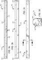
- FIG. 1is a bottom perspective view of a linear light fixture according to an embodiment of the present invention.
- FIG. 2is an exploded view of a linear light fixture according to an embodiment of the present invention.
- FIGS. 3 a - dare various elevation views of a linear light fixture according to an embodiment of the present invention ( 3 a : bottom elevation; 3 b : right side elevation; 3 c : top elevation; and 3 d : right end elevation).
- FIG. 4is a close-up cutaway view (along cut line A-A′) of a portion of a linear light fixture according to an embodiment of the present invention.
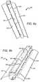
- FIGS. 5 a and 5 bare perspective views of a gap filler element according to an embodiment of the present invention.
- FIGS. 5 c - fare various elevation views of a gap filler element according to an embodiment of the present invention ( 5 c : right end elevation; 5 d : bottom elevation; 5 e : right side elevation; and 5 f : top elevation).
- FIG. 6is a perspective view of a portion of a linear light fixture according to an embodiment of the present invention.
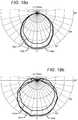
- FIGS. 7 a and 7 bare polar graphs showing radiant intensity (W/sr) versus viewing angle (degrees) of light fixtures.
- FIG. 7 cshows zonal lumen summaries for these fixtures.
- FIG. 8 ais a bottom perspective view of a linear light fixture according to an embodiment of the present invention.
- FIG. 8 bis a top perspective view of the fixture.
- FIG. 8 cis a right end elevation view of the fixture.
- FIG. 9is a bottom perspective view of a linear light fixture with reflectors according to an embodiment of the present invention.
- FIGS. 10 a and 10 bare polar graphs showing radiant intensity (W/sr) versus viewing angle (degrees) of a simulated light fixture according to an embodiment of the present invention compared with existing fixtures.
- FIG. 10 cshows zonal lumen summaries for these fixtures.
- FIG. 11is a bottom perspective view of a linear light fixture with reflectors according to an embodiment of the present invention.
- FIGS. 12 a and 12 bare polar graphs showing radiant intensity (W/sr) versus viewing angle (degrees) of simulated light fixtures.
- FIG. 12 cshows a zonal lumen summary for the fixture.
- FIG. 13is a bottom perspective view of a linear light fixture with reflectors according to an embodiment of the present invention.
- FIGS. 14 a and 14 bare polar graphs showing radiant intensity (W/sr) versus viewing angle (degrees) of a simulated light fixture according to an embodiment of the present invention compared with other simulated fixtures.
- FIG. 14 cshows a zonal lumen summary for the simulated fixture.
- FIG. 15is a bottom perspective view of a linear light fixture with reflectors according to an embodiment of the present invention.
- FIGS. 16 a and 16 bare polar graphs showing radiant intensity (W/sr) versus viewing angle (degrees) of a simulated light fixture according to an embodiment of the present invention compared with other simulated fixtures.
- FIG. 16 cshows a zonal lumen summary for the simulated fixture.
- FIG. 17is a bottom perspective view of a linear light fixture with reflectors according to an embodiment of the present invention.
- FIGS. 18 a and 18 bare polar graphs showing radiant intensity (W/sr) versus viewing angle (degrees) of a simulated light fixture according to an embodiment of the present invention compared with other simulated fixtures.
- FIG. 18 cshows a zonal lumen summary for the simulated fixture.
- Embodiments of the present inventionprovide linear light fixture that is particularly well-suited for use with solid state light sources, such as LEDs, to provide a surface ambient light (SAL).
- the fixturecomprises two primary structural components: a base and a light engine. These two subassemblies may be removably attached to operate as a singular fixture.
- the basecomprises a body with end panels at both ends and is mountable to an external structure.
- the light enginecomprises the light sources, an elongated lens, and any other optical elements that tailor the outgoing light to a particular profile.
- a gap filler elementis disposed between the light engine and the end panels at one or both ends of the base to fill the space between those elements, giving the appearance that the light engine extends continuously to the end panel and eliminating direct imaging of the light sources outside the fixture.
- Electronics necessary to power and control the light sourcesmay be disposed in either the base or the light engine.
- External reflectorsmay also be included to further shape the output beam.
- the term “emitter”can be used to indicate a single light source or more than one light source functioning as a single emitter.
- the termmay be used to describe a single blue LED, or it may be used to describe a red LED and a green LED in proximity emitting as a single source.
- the term “emitter”may indicate a single LED chip or multiple LED chips arranged in an array, for example.
- the terms “source” and “emitter”should not be construed as a limitation indicating either a single-element or a multi-element configuration unless clearly stated otherwise. Indeed, in many instances the terms “source” and “emitter” may be used interchangeably.
- an emittermay be any device that emits light, including but not limited to LEDs, vertical-cavity surface-emitting lasers (VCSELs), and the like.
- coloras used herein with reference to light is meant to describe light having a characteristic average wavelength; it is not meant to limit the light to a single wavelength.
- light of a particular colore.g., green, red, blue, yellow, etc.
- Embodiments of the inventionare described herein with reference to cross-sectional and/or cutaway views that are schematic illustrations. As such, the actual thickness of elements can be different, and variations from the shapes of the illustrations as a result, for example, of manufacturing techniques and/or tolerances are expected. Thus, the elements illustrated in the figures are schematic in nature and their shapes are not intended to illustrate the precise shape of a region of a device and are not intended to limit the scope of the invention.
- FIG. 1is a perspective view of a linear light fixture 100 according to an embodiment of the present invention.
- the fixture 100is particularly well-suited for use with solid state light emitters, such as LEDs or vertical cavity surface emitting lasers (VCSELs), for example.
- solid state light emitterssuch as LEDs or vertical cavity surface emitting lasers (VCSELs)
- VCSELsvertical cavity surface emitting lasers
- other kinds of light sourcesmay also be used.
- the elongated fixture 100comprises a base 102 and a light engine 104 .
- the two subassemblies 102 , 104are removably attached as shown.
- the base 102 and the light engine 104define an internal cavity that houses several elements including the light sources and the driver electronics as shown in detail herein.
- the base 102is designed to work with different light engine subassemblies such that they may be easily replaced to achieve a particular lighting effect, for example.
- FIG. 2is an exploded view of the fixture 100 .
- FIGS. 3 a - dprovide several different elevation views of the fixture 100 .
- FIG. 3 ais a bottom elevation view
- FIG. 3 bis a right side perspective view, with the left side view being identical
- FIG. 3 cis top elevation view
- FIG. 3 dis a right end view, with the left end being view being identical.
- the elongated base 102forms the primary structural body of the fixture 100 .
- driver electronics 202are mounted on an interior surface within the base 102 .
- the base 102also comprises two integral end panels 204 on both ends.
- the light engine 104comprises a mount plate 206 as the primary structural component.
- the mount plate 206provides a flat surface on which a plurality of light sources 208 may be mounted.
- the light sources 208are disposed on a pre-fabricated light strip 210 which is mounted to the mount plate 206 with, e.g., screws 212 or other fastening means.
- An elongated lens 214is attached to the mount plate 206 and covers the light sources 208 .
- the lens 214performs a dual function; it both protects components within the internal cavity and shapes and/or diffuses the outgoing light.
- gap filler elements 216are arranged between both end panels 204 of the base 102 and the ends of the light engine 104 .
- a single gap filler elementmay be used at one end of the fixture. Gap filler elements are discussed in more detail herein.
- mount brackets 218that may be used to mount the fixture 100 to a ceiling or a T-grid, for example.
- the fixture 100can be mounted in many different ways. For example, it can be surface mounted to a wall, a ceiling, or another surface, or it can be suspended from the ceiling with aircraft cable or in a pendant configuration.
- the top side of the fixture 100may include various screw holes and knockouts to accommodate internally mounted driver electronics, for example.
- knockouts the ends of the base 102may also comprise knockouts to provide access to internal components.
- screw holes, slots, knockouts, etc.may be arranged on the base 102 in various places to accommodate internal and external components as necessary.
- FIG. 4is a close-up cutaway side view of the fixture along cut line A-A′.
- the electronic components 202are mounted on the interior of the base 102 along the longitudinal axis.
- the mount plate 206comprises tabs 402 that mate with slots 404 in the base to removably attach the two components base 102 and the light engine 104 .
- the base 102can receive many different light engines to provide a fixture having a desired optical effect and also to facilitate replacement if a light engine is damaged or otherwise malfunctions. Thus, the base 102 functions as a universal receiving structure for various embodiments of light engines.
- the mount plate 206bends back on itself to form a flange 406 , and the lens 214 is shaped to define a longitudinal groove 408 .
- the groove 408receives the flange 406 to align the lens with the mount plate 206 and to hold them together, forming the light engine 104 . Also visible is the gap filler tab 502 which protrudes through the mount plate 206 , allowing the gap filler 216 to be removably fastened to the light engine 104 as described in more detail herein.
- Embodiments of the present inventioncomprise the gap filler elements 216 to account for these gaps.
- the gap fillers 216fill the space with a translucent material that gives the appearance that the light engine 104 extends all the way to the end panel 204 of the base 102 . Because the light sources 208 are no long visible through the gaps, source imaging is eliminated.
- the gap fillers 216compensate for inconsistency in lens manufacturing, allowing for a much more relaxed tolerance for lens length.
- FIGS. 5 a - fshow several views of a gap filler element 216 according to an embodiment of the present invention.
- FIG. 5 ais front perspective view
- FIG. 5 bis a back side perspective view
- FIG. 5 cis a front elevation view
- FIG. 5 dis a top elevation view
- FIG. 5 eis a side elevation view
- FIG. 5 fis a bottom elevation view.
- the gap filler 216is removably attachable to the light engine 104 such that, when assembled, the gap filler 216 is interposed between the end panel 204 of the base 102 and the end of light engine 104 .
- the gap filler 216comprises tabs 502 that snap-fit into corresponding slots on the mount plate 206 , fastening the gap filler 216 to the light engine 104 .
- the snap-fit fastening mechanismallows for easier and faster assembly without the need for screws or adhesives.
- the gap filler 216also comprises a spacer portion 504 and a ridge 506 .
- the spacer portion 504is shaped to mimic the external contour of the lens 214 such that the lens 214 appears to extend continuously to the end panel 204 .
- the ridge 506protrudes from said spacer portion 504 and is shaped to conform to an interior surface of the lens 214 .
- the width of the ridge 506is designed to compensate for a maximum deviation from length specification, with a wider ridge allowing for a more relaxed tolerance.
- the gap fillers 216comprise a light-transmissive (e.g., translucent) material.
- the materialshould diffuse the light sufficiently to prevent source imaging with the optimal diffusion providing an output that is similar in appearance to that emitted from the lens 214 .
- the gap filler 216does not need to be as diffusive as the lens 214 because most of the light that exits the gap filler 216 will exit from its edge.
- suitable materialsinclude polycarbonates or acrylics.
- FIG. 6is a close-up perspective view of the fixture 100 , fully assembled.
- the gap filler 216is interposed between the end panel 204 of the base 102 and the lens 214 of the light engine 104 .
- the gap filler ridge 506fits just under the lens 214 with the tabs 502 snap-fitting into the mount plate 206 .
- the spacer portion 504fills most of the gap between the lens 214 and the end panel 204 , giving the fixture 100 a fully luminous appearance all the way to the end panels 204 .
- gap fillers 216can be used at one or both ends of a fixture.
- the driver electronics 202comprise a step-down converter, a driver circuit, and a battery backup.
- a driver circuitmay comprise an AC/DC converter, a DC/DC converter, or both.
- the driver circuitcomprises an AC/DC converter and a DC/DC converter both of which are located in the base 102 .
- the AC/DC conversionis done in the base 102
- the DC/DC conversionis done in the light engine 104 .
- Another embodimentuses the opposite configuration where the DC/DC conversion is done in the base 102 , and the AC/DC conversion is done in the light engine 104 .
- both the AC/DC converter and the DC/DC converterare located in the light engine 104 . It is understood that the various electronic components may distributed in different ways in one or both of the base 102 and the light engine 104 .
- the lens 214comprises a diffusive element.
- a diffusive exit lens 214functions in several ways. For example, it can prevent direct visibility of the sources and provide additional mixing of the outgoing light to achieve a visually pleasing uniform source. However, a diffusive exit lens can introduce additional optical loss into the system. Thus, in embodiments where the light is sufficiently mixed internally by other elements, a diffusive exit lens may be unnecessary. In such embodiments, a transparent exit lens may be used, or the exit lens may be removed entirely. In still other embodiments, scattering particles may be included in the exit lens 214 .
- Diffusive elements in the lens 214can be achieved with several different structures.
- a diffusive film inlaycan be applied to the top- or bottom-side surface of the lens 214 . It is also possible to manufacture the lens 214 to include an integral diffusive layer, such as by coextruding the two materials or by insert molding the diffuser onto the exterior or interior surface.
- a clear lensmay include a diffractive or repeated geometric pattern rolled into an extrusion or molded into the surface at the time of manufacture.
- the exit lens materialitself may comprise a volumetric diffuser, such as an added colorant or particles having a different index of refraction, for example.
- the lens 214may be used to optically shape the outgoing beam with the use of microlens structures, for example.
- Microlens structuresare discussed in detail in U.S. patent application Ser. No. 13/442,311 to Lu, et al., which is commonly assigned with the present application to CREE, INC. and incorporated by reference herein.
- FIGS. 7 a and 7 bare polar graphs of measured radiant intensity (W/sr) over the entire range of viewing angles of the light fixture 100 compared with a standard 2-lamp fluorescent strip. Two data sets are represented on both graphs: the fixture 100 data sets 702 , 706 and the data sets 704 , 708 for the standard fluorescent strip, with both all data sets scaled to 4500 lumens.
- W/srmeasured radiant intensity
- the data sets 702 , 704illustrate radiant intensity coming from the fixtures as the viewing angle is swept from 0° to 360° along a longitudinal plane (y-z plane) down the center, with 0° representing the head-on view (i.e., directly in front of the light fixture on the lens side) and 180° representing the back side view (i.e., directly behind the light fixture from the base side).
- the data sets 706 , 708show the radiant intensity coming from the fixtures as the viewing angle is swept from 0° to 360° along a transverse plane (x-z plane) through the center of one of the emitters. All of the polar graphs disclosed herein were generated with the same modeled measurement method.
- FIG. 7 cprovides zonal lumen summaries for the fixture 100 and the standard fluorescent strip.
- FIG. 8 ais a perspective view of a fixture 800 according to an embodiment of the present invention.
- the fixture 800is similar to the fixture 100 except that the fixture 800 additionally comprises elongated reflectors 802 that extend away from the base 102 on run along the length of the fixture 800 on both sides.
- the reflectorsmay be shaped to define holes, louvres, perforations, and the like, as shown in exemplary embodiments disclosed herein. In some applications it is desirable to direct some light in both directions, for example, to light both a ceiling and the room beneath it.
- the reflectors 802comprise a plurality of louvres 804 which redirect some of the high angle light as uplight.
- the louvres 804protrude down into the normal path of the light that exits the fixture such that a portion of it is captured and redirected by the louvres 804 through the reflector 802 , providing uplight.
- the term uplightis used to describe light that illuminates an area that would normally considered to behind the intended direction of emission for the fixture.
- uplightrefers to light from the fixture that illuminates the ceiling around the fixture. Many different sizes and shapes of holes may be cut into reflectors to provide a particular uplight profile.
- the uplightcan be provided using a combination of reflective structures and holes such as the louvres 804 . Holes and louvres can be provided on one or both reflectors depending on the desired output profile.
- FIG. 8 bshows a top side perspective view of the fixture 800 .
- FIG. 8 cshows a right end elevation view of the fixture 800 .
- the reflectors 802can be attached to the fixture in several ways. Here, the reflectors 802 are attached to the top side of the base, using a snap-fit fasteners 806 .
- the reflectors 802comprise back side flanges 808 that provide a mounting means to the top of the fixture base.
- a male snap-fit connectormates with a female connector cut into the fixture base to provide the snap-fit fastener 806 .
- the following exemplary embodimentsfeature fixtures similar to the fixture 100 , each comprising a different reflector shaped and sized to provide a particular output profile.
- FIG. 9is a bottom side perspective view of a fixture 900 according to an embodiment of the present invention.
- the fixture 900is similar to fixture 100 with the addition of wide solid reflectors 902 that extend away from the fixture body and run along the length of the fixture 900 .
- the fixture 900provides an output that is characterized by the data represented in FIGS. 10 a - c.
- FIGS. 10 a and 10 bare polar graphs of modeled radiant intensity (W/sr) over the entire range of viewing angles of a simulated fixture 900 compared with two other kinds of fixtures.
- Three data setsare represented on both graphs: the fixture 900 data sets 1002 , 1008 , the data sets 1004 , 1010 for an industrial fluorescent strip, and the data sets 1006 , 1012 for a CS18 LED Linear Luminaire (commercially available from Cree, Inc.; http://www.cree.com/Lighting/Products/Indoor/High-Low-Bay/CS18) with all data sets scaled to 4500 lumens.
- Cree, Inc.http://www.cree.com/Lighting/Products/Indoor/High-Low-Bay/CS18
- the data sets 1002 , 1004 , 1006illustrate radiant intensity along the y-z plane.
- the data sets 1008 , 1010 , 1012show the radiant intensity as the viewing angle is swept from 0° to 360° along the x-z plane.
- FIG. 10 cprovides zonal lumen summaries for the fixture 900 , the industrial fluorescent strip, and the CS18 LED Linear Luminaire.
- FIG. 11is a bottom side perspective view of a fixture 1100 according to an embodiment of the present invention.
- the fixture 1100is similar to fixture 100 with the addition of narrow solid reflectors 1102 that extend away from the fixture body and run along the length of the fixture 1100 .
- the fixture 1100provides an output that is characterized by the data represented in FIGS. 12 a - c.
- FIGS. 12 a and 12 bare polar graphs of modeled radiant intensity (W/sr) over the entire range of viewing angles of a simulated fixture 1100 compared with the simulated fixture 100 .
- Two data setsare represented on both graphs: the fixture 1100 data sets 1202 , 1206 , the data sets 1204 , 1208 for the fixture 100 without reflectors, with both data sets scaled to 4500 lumens.
- the data sets 1202 , 1204illustrate radiant intensity along the y-z plane.
- the data sets 1206 , 1208show the radiant intensity coming from the fixtures as the viewing angle is swept from 0° to 360° along the x-z plane.
- FIG. 12 cprovides zonal lumen summaries for the fixture 1100 .
- FIG. 13is a bottom side perspective view of a fixture 1300 according to an embodiment of the present invention.
- the fixture 1300is similar to fixture 100 with the addition of reflectors 1302 that extend away from the fixture body and run along the length of the fixture 1300 .
- the reflectors 1302are shaped to define a plurality of crescent slots to allow for more uplight.
- the fixture 1300provides an output that is characterized by the data represented in FIGS. 14 a - c.
- FIGS. 14 a and 14 bare polar graphs of modeled radiant intensity (W/sr) over the entire range of viewing angles of a simulated fixture 1300 compared with the simulated fixture 100 and the fixture 1100 .
- Three data setsare represented on both graphs: the fixture 1300 data sets 1402 , 1408 , the data sets 1404 , 1410 for the fixture 100 without reflectors, and the data sets for the fixture 1100 , with all data sets scaled to 4500 lumens.
- the data sets 1402 , 1404 , 1406illustrate radiant intensity along the y-z plane.
- FIG. 14 cprovides zonal lumen summaries for the fixture 1300 .
- FIG. 15is a bottom side perspective view of a fixture 1500 according to an embodiment of the present invention.
- the fixture 1500is similar to fixture 100 with the addition of reflectors 1502 that extend away from the fixture body and run along the length of the fixture 1500 .
- the reflectors 1502are shaped to define a plurality of linear slots to allow for more uplight.
- the fixture 1500provides an output that is characterized by the data represented in FIGS. 16 a - c.
- FIGS. 16 a and 16 bare polar graphs of modeled radiant intensity (W/sr) over the entire range of viewing angles of a simulated fixture 1500 compared with the simulated fixture 100 and the fixture 1100 .
- Three data setsare represented on both graphs: the fixture 1500 data sets 1602 , 1608 , the data sets 1604 , 1610 for the fixture 100 without reflectors, and the data sets 1606 , 1612 for the fixture 1100 , with all data sets scaled to 4500 lumens.
- the data sets 1602 , 1604 , 1606illustrate radiant intensity along the y-z plane.
- FIG. 16 cprovides zonal lumen summaries for the fixture 1500 .
- FIG. 17is a bottom side perspective view of a fixture 1700 according to an embodiment of the present invention.
- the fixture 1700is similar to fixture 100 with the addition of reflectors 1702 that extend away from the fixture body and run along the length of the fixture 1700 .
- the reflectors 1702are wider and shaped to define a plurality of linear slots to allow for more uplight.
- the fixture 1700provides an output that is characterized by the data represented in FIGS. 18 a - c.
- FIGS. 18 a and 18 bare polar graphs of modeled radiant intensity (W/sr) over the entire range of viewing angles of a simulated fixture 1700 compared with the simulated fixture 100 and the fixture 1100 .
- Three data setsare represented on both graphs: the fixture 1700 data sets 1802 , 1808 , the data sets 1804 , 1810 for the fixture 100 without reflectors, and the data sets 1806 , 1812 for the fixture 1100 , with all data sets scaled to 4500 lumens.
- the data sets 1802 , 1804 , 1806illustrate radiant intensity along the y-z plane.
- FIG. 18 cprovides zonal lumen summaries for the fixture 1700 .
Landscapes
- Engineering & Computer Science (AREA)
- General Engineering & Computer Science (AREA)
- Non-Portable Lighting Devices Or Systems Thereof (AREA)
- Microelectronics & Electronic Packaging (AREA)
Abstract
Description
Claims (18)
Priority Applications (2)
| Application Number | Priority Date | Filing Date | Title |
|---|---|---|---|
| US14/108,168US10612747B2 (en) | 2013-12-16 | 2013-12-16 | Linear shelf light fixture with gap filler elements |
| US14/252,685US10100988B2 (en) | 2013-12-16 | 2014-04-14 | Linear shelf light fixture with reflectors |
Applications Claiming Priority (1)
| Application Number | Priority Date | Filing Date | Title |
|---|---|---|---|
| US14/108,168US10612747B2 (en) | 2013-12-16 | 2013-12-16 | Linear shelf light fixture with gap filler elements |
Related Child Applications (1)
| Application Number | Title | Priority Date | Filing Date |
|---|---|---|---|
| US14/252,685Continuation-In-PartUS10100988B2 (en) | 2013-12-16 | 2014-04-14 | Linear shelf light fixture with reflectors |
Publications (2)
| Publication Number | Publication Date |
|---|---|
| US20150167901A1 US20150167901A1 (en) | 2015-06-18 |
| US10612747B2true US10612747B2 (en) | 2020-04-07 |
Family
ID=53367916
Family Applications (1)
| Application Number | Title | Priority Date | Filing Date |
|---|---|---|---|
| US14/108,168Active2033-12-30US10612747B2 (en) | 2013-12-16 | 2013-12-16 | Linear shelf light fixture with gap filler elements |
Country Status (1)
| Country | Link |
|---|---|
| US (1) | US10612747B2 (en) |
Cited By (10)
| Publication number | Priority date | Publication date | Assignee | Title |
|---|---|---|---|---|
| US10989372B2 (en) | 2017-03-09 | 2021-04-27 | Ecosense Lighting Inc. | Fixtures and lighting accessories for lighting devices |
| US11022279B2 (en) | 2016-03-08 | 2021-06-01 | Ecosense Lighting Inc. | Lighting system with lens assembly |
| US11028980B2 (en) | 2013-10-30 | 2021-06-08 | Ecosense Lighting Inc. | Flexible strip lighting apparatus and methods |
| US11041609B2 (en) | 2018-05-01 | 2021-06-22 | Ecosense Lighting Inc. | Lighting systems and devices with central silicone module |
| US11137131B2 (en)* | 2016-04-29 | 2021-10-05 | Vode Lighting, LLC | Light injected terminal lensing and coupling device |
| US11296057B2 (en) | 2017-01-27 | 2022-04-05 | EcoSense Lighting, Inc. | Lighting systems with high color rendering index and uniform planar illumination |
| US11353200B2 (en) | 2018-12-17 | 2022-06-07 | Korrus, Inc. | Strip lighting system for direct input of high voltage driving power |
| US11933464B2 (en) | 2020-09-07 | 2024-03-19 | Ideal Industries Lighting Llc | Light strip |
| US12320492B1 (en) | 2023-12-04 | 2025-06-03 | Leviton Manufacturing Co., Inc. | Lighting fixture systems |
| US12388056B1 (en) | 2017-01-27 | 2025-08-12 | Korrus, Inc. | Linear lighting systems and processes |
Families Citing this family (5)
| Publication number | Priority date | Publication date | Assignee | Title |
|---|---|---|---|---|
| DE202015105430U1 (en)* | 2015-10-14 | 2017-01-17 | Zumtobel Lighting Gmbh | Elongated light |
| JP6741986B2 (en)* | 2016-04-26 | 2020-08-19 | パナソニックIpマネジメント株式会社 | lighting equipment |
| US11118758B1 (en)* | 2020-11-03 | 2021-09-14 | Elemental LED, Inc. | Louvered optics for linear lighting |
| USD994947S1 (en)* | 2021-08-20 | 2023-08-08 | Xiamen Longstar Lighting Co., Ltd. | Integrated light emitting diode (LED) pendant lamp |
| USD994948S1 (en)* | 2021-08-20 | 2023-08-08 | Xiamen Longstar Lighting Co., Ltd. | Integrated light emitting diode (LED) pendant lamp |
Citations (153)
| Publication number | Priority date | Publication date | Assignee | Title |
|---|---|---|---|---|
| US3589660A (en) | 1970-03-05 | 1971-06-29 | Nat Service Ind Inc | Lighting fixture hanger |
| US4118763A (en) | 1976-04-12 | 1978-10-03 | General Electric Company | Variable transmission prismatic refractors |
| US4300185A (en) | 1979-12-07 | 1981-11-10 | C. W. Cole & Company, Inc. | Light fixture unit for open plan office |
| US4464707A (en) | 1982-03-17 | 1984-08-07 | Louis Forrest | Lighting fixture |
| US4472767A (en) | 1981-12-23 | 1984-09-18 | Mcgraw-Edison Company | Reflector assembly for indirect or semi-indirect lighting fixture |
| US4946547A (en) | 1989-10-13 | 1990-08-07 | Cree Research, Inc. | Method of preparing silicon carbide surfaces for crystal growth |
| US5200022A (en) | 1990-10-03 | 1993-04-06 | Cree Research, Inc. | Method of improving mechanically prepared substrate surfaces of alpha silicon carbide for deposition of beta silicon carbide thereon and resulting product |
| US5335890A (en) | 1992-07-20 | 1994-08-09 | Pryor Products, Inc. | Ceiling track mounting apparatus |
| USRE34861E (en) | 1987-10-26 | 1995-02-14 | North Carolina State University | Sublimation of silicon carbide to produce large, device quality single crystals of silicon carbide |
| US5530628A (en) | 1993-04-05 | 1996-06-25 | Peerless Lighting Corporation | Task light |
| US5653412A (en) | 1994-11-14 | 1997-08-05 | Cooper Industries, Inc. | Track mounting clip for a track lighting system |
| US5690415A (en) | 1995-11-29 | 1997-11-25 | Stylmark, Inc. | Display light |
| US5823663A (en) | 1996-10-21 | 1998-10-20 | National Service Industries, Inc. | Fluorescent troffer lighting fixture |
| US5907218A (en)* | 1996-12-09 | 1999-05-25 | The Whitaker Corporation | Fluorescent lighting assembly with integral ballast |
| US5951150A (en) | 1997-09-11 | 1999-09-14 | Eaton Corporation | Display system |
| US6190198B1 (en) | 1996-03-21 | 2001-02-20 | Peter Ray | Electrical fittings for suspended ceilings |
| US6210025B1 (en) | 1999-07-21 | 2001-04-03 | Nsi Enterprises, Inc. | Lensed troffer lighting fixture |
| US20010048599A1 (en) | 2000-05-10 | 2001-12-06 | Jean-Marc Hess | Light distributor for a lighting device and lighting device and use of a lighting device |
| US6350041B1 (en) | 1999-12-03 | 2002-02-26 | Cree Lighting Company | High output radial dispersing lamp using a solid state light source |
| US6435697B1 (en)* | 2001-02-02 | 2002-08-20 | Joseph E. Simmons | Exterior lighting system |
| US6536924B2 (en) | 2001-02-28 | 2003-03-25 | Jji Lighting Group, Inc. | Modular lighting unit |
| US6667451B1 (en) | 2003-03-20 | 2003-12-23 | Eaton Corporation | Push button assembly |
| US6739734B1 (en) | 2003-03-17 | 2004-05-25 | Ultimate Presentation Sytems, Inc. | LED retrofit method and kit for converting fluorescent luminaries |
| US20040109330A1 (en)* | 2002-12-04 | 2004-06-10 | Jean Pare | Illuminated LED street sign |
| US20040240214A1 (en) | 2003-05-28 | 2004-12-02 | Hubbell Incorporated. | Light fixture having air ducts |
| US20040252521A1 (en) | 2003-06-13 | 2004-12-16 | Finelite | Free-cavity, double-diffusing indirect lighting luminaire |
| US20050007033A1 (en)* | 2003-07-09 | 2005-01-13 | Tir Systems Ltd. | Strip lighting system incorporating light emitting devices |
| US20050041418A1 (en)* | 2003-08-19 | 2005-02-24 | Ben Fan | Neon light using a rope light as a light source |
| US6914194B2 (en) | 2003-10-29 | 2005-07-05 | Ben Fan | Flexible LED cable light |
| US20050146867A1 (en) | 2003-12-31 | 2005-07-07 | Kassay Charles E. | Fluorescent lighting fixtures with controlled uplight capability |
| CN1710323A (en) | 2004-06-18 | 2005-12-21 | 艾柯蒂布兰兹公司 | Light fixtures and lens assemblies for light fixtures |
| US20060050505A1 (en) | 2002-05-28 | 2006-03-09 | Kenall Manufacturing Company | Selectively-extendable modular lighting fixture and method |
| US7131747B1 (en) | 2003-12-29 | 2006-11-07 | Yates James P | Length adjustment device for illuminated fascia |
| US20060266955A1 (en) | 2005-05-24 | 2006-11-30 | Dubois Equipment Company, Inc. | Apparatus for curing a coating on a three-dimensional object |
| US20060278882A1 (en)* | 2005-06-10 | 2006-12-14 | Cree, Inc. | Power lamp package |
| CN2872082Y (en) | 2006-01-18 | 2007-02-21 | 深圳市海洋王投资发展有限公司 | Efficient ceiling light of gymnasium |
| US7213940B1 (en) | 2005-12-21 | 2007-05-08 | Led Lighting Fixtures, Inc. | Lighting device and lighting method |
| US7217023B2 (en) | 2002-08-01 | 2007-05-15 | Toyoda Gosei Co., Ltd. | Linear luminous body and linear luminous structure |
| US20070109330A1 (en) | 2001-05-09 | 2007-05-17 | Clairvoyante, Inc | Conversion of a sub-pixel format data to another sub-pixel data format |
| US7228253B2 (en) | 2004-08-19 | 2007-06-05 | Pacific Telescope Corp. | Instrument mounting system with dual encoders |
| US20070158668A1 (en) | 2005-08-25 | 2007-07-12 | Cree, Inc. | Close loop electrophoretic deposition of semiconductor devices |
| US20070171647A1 (en) | 2006-01-25 | 2007-07-26 | Anthony, Inc. | Control system for illuminated display case |
| US20070183148A1 (en)* | 2004-06-18 | 2007-08-09 | Mayfield John T Iii | Light fixture |
| US7267461B2 (en) | 2004-01-28 | 2007-09-11 | Tir Systems, Ltd. | Directly viewable luminaire |
| US7303310B2 (en) | 2006-03-23 | 2007-12-04 | Opto Tech Corp. | Structure for a high efficiency and water-proof lighting device |
| WO2008003289A2 (en) | 2006-07-06 | 2008-01-10 | Osram Gesellschaft mit beschränkter Haftung | Illuminating system of flexible shape |
| US20080128723A1 (en) | 2006-12-04 | 2008-06-05 | Siew It Pang | Low Thermal Resistance High Power LED |
| US7387410B2 (en) | 2004-09-07 | 2008-06-17 | C.E.I.T. Corp. | Luminaire assembly and method |
| US20080173884A1 (en) | 2007-01-22 | 2008-07-24 | Cree, Inc. | Wafer level phosphor coating method and devices fabricated utilizing method |
| US20080179611A1 (en) | 2007-01-22 | 2008-07-31 | Cree, Inc. | Wafer level phosphor coating method and devices fabricated utilizing method |
| US20080258130A1 (en) | 2007-04-23 | 2008-10-23 | Bergmann Michael J | Beveled LED Chip with Transparent Substrate |
| US20080285267A1 (en) | 2007-04-10 | 2008-11-20 | Ledalite Architectural Products, Inc. | Light control device exhibiting batwing luminous intensity distributions in upper and lower hemispheres |
| US20080314944A1 (en)* | 2007-06-21 | 2008-12-25 | Cheng-Yu Tsai | Assembly for fixing and connecting light bar lamp |
| US20090009999A1 (en) | 2007-07-06 | 2009-01-08 | Bily Wang | LED lamp structure and system with high-efficiency heat-dissipating function |
| US20090040782A1 (en) | 2007-08-08 | 2009-02-12 | Ledtech Electronics Corp. | Led lighting device |
| US20090046457A1 (en) | 2007-08-13 | 2009-02-19 | Everhart Robert L | Solid-state lighting fixtures |
| US7520636B2 (en) | 2005-11-11 | 2009-04-21 | Koninklijke Philips Electronics N.V. | Luminaire comprising LEDs |
| US7540627B2 (en) | 2006-05-08 | 2009-06-02 | Innovative Lighting, Inc. | Channel light system with pivotable connector |
| US20090161356A1 (en) | 2007-05-30 | 2009-06-25 | Cree Led Lighting Solutions, Inc. | Lighting device and method of lighting |
| US7559672B1 (en) | 2007-06-01 | 2009-07-14 | Inteled Corporation | Linear illumination lens with Fresnel facets |
| US20090184333A1 (en) | 2008-01-17 | 2009-07-23 | Foxsemicon Integrated Technology, Inc. | Light emitting diode device |
| US20090185379A1 (en) | 2008-01-23 | 2009-07-23 | Chia-Yi Chen | LED light device having heat dissipating structure |
| US20090207602A1 (en) | 2005-09-06 | 2009-08-20 | Reed Mark C | Linear lighting system |
| US20090212304A1 (en) | 2008-02-22 | 2009-08-27 | Bily Wang | Led chip package structure with multifunctional integrated chips and a method for making the same |
| US20090224265A1 (en) | 2008-03-05 | 2009-09-10 | Bily Wang | LED chip package structure with a high-efficiency heat-dissipating substrate and method for making the same |
| US7591578B2 (en) | 2006-01-21 | 2009-09-22 | Hon Hai Precision Industry Co., Ltd. | Edge type backlight module having a reflective plate |
| US20090290348A1 (en) | 2006-04-16 | 2009-11-26 | Peter Van Laanen | Thermal Management Of LED-Based Lighting Systems |
| US20090290345A1 (en) | 2008-05-20 | 2009-11-26 | Apl Ip Holding Llc | Enclosures for led circuit boards |
| US20090296381A1 (en)* | 2008-06-01 | 2009-12-03 | Jack Dubord | Adjustable modular lighting system and method of using same |
| US7628506B2 (en) | 2005-10-03 | 2009-12-08 | Orion Energy Systems, Inc. | Modular light fixture with power pack and radiative, conductive, and convective cooling |
| US20100002426A1 (en)* | 2008-06-25 | 2010-01-07 | Hubbell Incorporated | Multi-directional lighting fixture |
| US20100014289A1 (en) | 2007-06-13 | 2010-01-21 | ElectraLED Inc. | Multiple use LED light fixture |
| KR20100012997A (en) | 2008-07-30 | 2010-02-09 | 한밭대학교 산학협력단 | Automatic toothpaste extruder |
| US7674005B2 (en) | 2004-07-29 | 2010-03-09 | Focal Point, Llc | Recessed sealed lighting fixture |
| US20100110701A1 (en)* | 2008-10-30 | 2010-05-06 | Fu Zhun Precision Industry (Shen Zhen) Co., Ltd. | Led lamp |
| US7722220B2 (en) | 2006-05-05 | 2010-05-25 | Cree Led Lighting Solutions, Inc. | Lighting device |
| US20100128485A1 (en)* | 2008-07-23 | 2010-05-27 | Ledtech Electronics Corp. | Custom assembly light-emitting module |
| US20100142205A1 (en) | 2008-12-08 | 2010-06-10 | Avx Corporation | Two part surface mount led strip connector and led assembly |
| US20100155763A1 (en) | 2008-01-15 | 2010-06-24 | Cree, Inc. | Systems and methods for application of optical materials to optical elements |
| US20100171404A1 (en) | 2009-01-07 | 2010-07-08 | Fu Zhun Precision Industry (Shen Zhen) Co., Ltd. | Led lamp |
| US7758207B1 (en)* | 2009-03-17 | 2010-07-20 | Fu Zhun Precision Industry (Shen Zhen) Co., Ltd. | Lightweight LED lamp |
| US20100214770A1 (en) | 2009-02-25 | 2010-08-26 | Anderson Kenneth E | Combination LED fixture and raceway |
| US20100220469A1 (en) | 2008-05-23 | 2010-09-02 | Altair Engineering, Inc. | D-shaped cross section l.e.d. based light |
| US7791061B2 (en) | 2004-05-18 | 2010-09-07 | Cree, Inc. | External extraction light emitting diode based upon crystallographic faceted surfaces |
| US20100259927A1 (en) | 2009-04-09 | 2010-10-14 | Chien Hsiao-Lou | Led lamp structure |
| US20100271804A1 (en) | 2009-04-22 | 2010-10-28 | Levine Jonathan E | Modular lighting device kit |
| US20100271825A1 (en)* | 2009-04-23 | 2010-10-28 | Integrated Illumination Systems, Inc. | Systems and methods for sealing a lighting fixture |
| US20100328945A1 (en) | 2009-06-30 | 2010-12-30 | Fu Zhun Precision Industry (Shen Zhen) Co., Ltd. | Led lamp |
| US20110007514A1 (en) | 2008-05-09 | 2011-01-13 | Sloanled, Inc. | Low profile extrusion |
| US20110006688A1 (en) | 2008-02-26 | 2011-01-13 | Shim Hyun-Seop | Led lamp device |
| US20110013400A1 (en) | 2009-07-16 | 2011-01-20 | Japan Aviation Electronics Industry, Limited | Socket, circuit board assembly, and apparatus having the same |
| US20110028006A1 (en) | 2008-03-20 | 2011-02-03 | Ashok Deepak Shah | Conductive Magnetic Coupling System |
| CN101984284A (en) | 2010-12-02 | 2011-03-09 | 安徽莱德光电技术有限公司 | Reflective LED grille lamp |
| CN101994939A (en) | 2009-08-19 | 2011-03-30 | Lg伊诺特有限公司 | Lighting device |
| US20110090682A1 (en)* | 2009-10-15 | 2011-04-21 | Fu Zhun Precision Industry (Shen Zhen) Co., Ltd. | Led tube |
| US20110103043A1 (en) | 2008-06-27 | 2011-05-05 | Optoworld Co., Ltd. | Device for Supporting Light Emitting Module |
| US20110163683A1 (en) | 2011-02-22 | 2011-07-07 | Quarkstar, Llc | Solid State Lamp Using Light Emitting Strips |
| US20110211330A1 (en) | 2010-03-01 | 2011-09-01 | Wen Wen Wang | Lighting apparatus |
| US20110222270A1 (en) | 2010-03-11 | 2011-09-15 | Silvio Porciatti | T-bar for suspended ceiling with heat dissipation system for LED lighting |
| US20110266282A1 (en)* | 2010-04-29 | 2011-11-03 | Defond Components Limited | Weather-proof sealing for enclosure |
| US8058088B2 (en) | 2008-01-15 | 2011-11-15 | Cree, Inc. | Phosphor coating systems and methods for light emitting structures and packaged light emitting diodes including phosphor coating |
| US20110286207A1 (en) | 2010-04-28 | 2011-11-24 | Cooper Technologies Company | Linear LED Light Module |
| US20110286208A1 (en) | 2010-05-24 | 2011-11-24 | Yu-Wen Chen | Light source assembly mechanism for led lamps |
| US20110285314A1 (en) | 2010-04-27 | 2011-11-24 | Cooper Technologies Company | Linkable Linear Light Emitting Diode System |
| US20110310604A1 (en)* | 2010-06-17 | 2011-12-22 | Rohm Co., Ltd. | Led lamp, lamp case, led module and led lighting apparatus |
| US20110310614A1 (en) | 2009-09-01 | 2011-12-22 | Budike Jr Lothar E S | Led light fixture having led modules |
| US20120002408A1 (en) | 2010-07-01 | 2012-01-05 | Jan Flemming Samuel Lichten | Lighting fixture for a poultry house |
| US20120020109A1 (en) | 2010-09-17 | 2012-01-26 | Lg Innotek Co., Ltd. | Lighting module and lighting apparatus including the same |
| US20120051041A1 (en) | 2010-08-31 | 2012-03-01 | Cree, Inc. | Troffer-Style Fixture |
| US20120075857A1 (en) | 2009-02-24 | 2012-03-29 | Koninklijke Philips Electronics N.V. | Directable magnetic mount for light emitter, a light source, a base and an illumination system |
| US20120081883A1 (en) | 2010-10-04 | 2012-04-05 | Yu-Chin Wang | Led lamp for aquarium |
| US20120092876A1 (en) | 2010-10-19 | 2012-04-19 | Chih-Yang Chang | Variable shaped lamp shade of led lamp |
| US20120098424A1 (en) | 2010-10-21 | 2012-04-26 | General Electric Company | Lighting system with thermal management system having point contact synthetic jets |
| US20120120666A1 (en) | 2009-05-13 | 2012-05-17 | Hella Kgaa Hueck & Co. | Street lighting device |
| US8206004B2 (en) | 2009-07-07 | 2012-06-26 | American Fluorescent Corporation | Distributed lighting apparatus |
| US20120169234A1 (en) | 2009-12-31 | 2012-07-05 | Shew Larry N | Light assembly |
| US8220953B1 (en) | 2011-11-08 | 2012-07-17 | TSM Associates, Inc. | Modular power grid illumination system |
| US20120201023A1 (en) | 2009-10-06 | 2012-08-09 | Ccs Inc. | Light irradiating device |
| US20120218757A1 (en) | 2009-11-05 | 2012-08-30 | Amoluxe Co., Ltd. | Lighting apparatus using light emitting diodes |
| US20120235199A1 (en) | 2002-09-04 | 2012-09-20 | Peter Scott Andrews | Power surface mount light emitting die package |
| US20120250302A1 (en)* | 2011-03-07 | 2012-10-04 | Greendot Technologies, Llc | Vapor-tight lighting fixture |
| US8313212B1 (en) | 2009-05-29 | 2012-11-20 | Usai, Llc | Modular lighting system and method |
| US8317369B2 (en) | 2009-04-02 | 2012-11-27 | Abl Ip Holding Llc | Light fixture having selectively positionable housing |
| US8342714B1 (en) | 2009-05-06 | 2013-01-01 | Stray Light Optical Technologies | Mobile lighting apparatus |
| US20130021803A1 (en) | 2011-07-24 | 2013-01-24 | Cree, Inc. | Light fixture with co-formed plenum component |
| US8360599B2 (en) | 2008-05-23 | 2013-01-29 | Ilumisys, Inc. | Electric shock resistant L.E.D. based light |
| US20130039090A1 (en) | 2011-08-08 | 2013-02-14 | Wilson Dau | Illumination Devices Including Multiple Light Emitting Elements |
| US8376578B2 (en) | 2009-06-12 | 2013-02-19 | Lg Innotek Co., Ltd. | Lighting device |
| US20130050998A1 (en) | 2011-08-25 | 2013-02-28 | Gt Biomescilt Light Limited | Light emitting diode lamp with light diffusing structure |
| US20130094224A1 (en)* | 2010-04-28 | 2013-04-18 | Tetsuya Miyatake | Light Emitting Apparatus And Light Emitting Apparatus Mount Structure |
| US20130093359A1 (en) | 2011-10-12 | 2013-04-18 | Econova Optronics Co., LTD. | Lighting device |
| US20130094225A1 (en) | 2011-10-17 | 2013-04-18 | Ecosense Lighting Inc. | Linear led light housing |
| US8459824B1 (en) | 2009-12-01 | 2013-06-11 | Ashkan Esmailzadeh | Lighting fixture |
| US20130155670A1 (en) | 2011-12-20 | 2013-06-20 | Innovative Lighting, Inc. | Lenticular led light source replacement for fluorescent in troffer |
| US8476836B2 (en) | 2010-05-07 | 2013-07-02 | Cree, Inc. | AC driven solid state lighting apparatus with LED string including switched segments |
| US8523383B1 (en) | 2010-02-19 | 2013-09-03 | Cooper Technologies Company | Retrofitting recessed lighting fixtures |
| US20130242548A1 (en)* | 2012-03-14 | 2013-09-19 | Zorak Ter-Hovhannisyan | Passive cooling lighting fixture |
| US20130258616A1 (en)* | 2012-03-28 | 2013-10-03 | Delta Electronics, Inc. | External structure of outdoor electronic apparatus |
| US20130271979A1 (en) | 2012-04-17 | 2013-10-17 | Dennis Pearson | Scalable LED Sconce Light |
| US20130279156A1 (en)* | 2012-04-23 | 2013-10-24 | Kohler Co. | Lighting assembly |
| US20130279180A1 (en) | 2012-04-23 | 2013-10-24 | Dennis Pearson | Commercial Lighting Integrated Platform |
| US20130329425A1 (en) | 2012-06-11 | 2013-12-12 | Cree, Inc. | Led package with encapsulant having planar surfaces |
| US20140043802A1 (en) | 2012-08-10 | 2014-02-13 | Luminaid B.V. | Linear led system |
| US20140085861A1 (en)* | 2012-09-26 | 2014-03-27 | Apogee Translite, Inc. | Lighting devices |
| US20140104843A1 (en)* | 2012-10-01 | 2014-04-17 | Abl Ip Holding Llc | Ceiling Mount Fixture |
| US8714770B2 (en) | 2008-08-01 | 2014-05-06 | Nichia Corporation | Lighting device |
| US20140265809A1 (en) | 2013-03-15 | 2014-09-18 | Cree, Inc. | Connector devices, systems, and related methods for light emitter components |
| US20140313731A1 (en) | 2013-04-23 | 2014-10-23 | Lg Innotek Co., Ltd. | Lighting device |
| US20150016100A1 (en)* | 2013-07-05 | 2015-01-15 | Toshiba Lighting & Technology Corporation | Luminaire |
| US20150022999A1 (en) | 2012-03-30 | 2015-01-22 | Samsung Electronics Co., Ltd. | Lighting device and method for manufacturing the same |
| US20150155427A1 (en)* | 2013-12-02 | 2015-06-04 | Samsung Electronics Co., Ltd. | Method of manufacturing lighting device |
| US9057493B2 (en) | 2010-03-26 | 2015-06-16 | Ilumisys, Inc. | LED light tube with dual sided light distribution |
| US20160025278A1 (en)* | 2013-08-30 | 2016-01-28 | Itc Incorporated | Led linear light assmeblies with transparent bottoms |
- 2013
- 2013-12-16USUS14/108,168patent/US10612747B2/enactiveActive
Patent Citations (160)
| Publication number | Priority date | Publication date | Assignee | Title |
|---|---|---|---|---|
| US3589660A (en) | 1970-03-05 | 1971-06-29 | Nat Service Ind Inc | Lighting fixture hanger |
| US4118763A (en) | 1976-04-12 | 1978-10-03 | General Electric Company | Variable transmission prismatic refractors |
| US4300185A (en) | 1979-12-07 | 1981-11-10 | C. W. Cole & Company, Inc. | Light fixture unit for open plan office |
| US4472767A (en) | 1981-12-23 | 1984-09-18 | Mcgraw-Edison Company | Reflector assembly for indirect or semi-indirect lighting fixture |
| US4464707A (en) | 1982-03-17 | 1984-08-07 | Louis Forrest | Lighting fixture |
| USRE34861E (en) | 1987-10-26 | 1995-02-14 | North Carolina State University | Sublimation of silicon carbide to produce large, device quality single crystals of silicon carbide |
| US4946547A (en) | 1989-10-13 | 1990-08-07 | Cree Research, Inc. | Method of preparing silicon carbide surfaces for crystal growth |
| US5200022A (en) | 1990-10-03 | 1993-04-06 | Cree Research, Inc. | Method of improving mechanically prepared substrate surfaces of alpha silicon carbide for deposition of beta silicon carbide thereon and resulting product |
| US5335890A (en) | 1992-07-20 | 1994-08-09 | Pryor Products, Inc. | Ceiling track mounting apparatus |
| US5530628A (en) | 1993-04-05 | 1996-06-25 | Peerless Lighting Corporation | Task light |
| US5653412A (en) | 1994-11-14 | 1997-08-05 | Cooper Industries, Inc. | Track mounting clip for a track lighting system |
| US5690415A (en) | 1995-11-29 | 1997-11-25 | Stylmark, Inc. | Display light |
| US6190198B1 (en) | 1996-03-21 | 2001-02-20 | Peter Ray | Electrical fittings for suspended ceilings |
| US5823663A (en) | 1996-10-21 | 1998-10-20 | National Service Industries, Inc. | Fluorescent troffer lighting fixture |
| US5907218A (en)* | 1996-12-09 | 1999-05-25 | The Whitaker Corporation | Fluorescent lighting assembly with integral ballast |
| US5951150A (en) | 1997-09-11 | 1999-09-14 | Eaton Corporation | Display system |
| US6210025B1 (en) | 1999-07-21 | 2001-04-03 | Nsi Enterprises, Inc. | Lensed troffer lighting fixture |
| US6350041B1 (en) | 1999-12-03 | 2002-02-26 | Cree Lighting Company | High output radial dispersing lamp using a solid state light source |
| US20010048599A1 (en) | 2000-05-10 | 2001-12-06 | Jean-Marc Hess | Light distributor for a lighting device and lighting device and use of a lighting device |
| US6435697B1 (en)* | 2001-02-02 | 2002-08-20 | Joseph E. Simmons | Exterior lighting system |
| US6536924B2 (en) | 2001-02-28 | 2003-03-25 | Jji Lighting Group, Inc. | Modular lighting unit |
| US20070109330A1 (en) | 2001-05-09 | 2007-05-17 | Clairvoyante, Inc | Conversion of a sub-pixel format data to another sub-pixel data format |
| US20060050505A1 (en) | 2002-05-28 | 2006-03-09 | Kenall Manufacturing Company | Selectively-extendable modular lighting fixture and method |
| US7217023B2 (en) | 2002-08-01 | 2007-05-15 | Toyoda Gosei Co., Ltd. | Linear luminous body and linear luminous structure |
| US20120235199A1 (en) | 2002-09-04 | 2012-09-20 | Peter Scott Andrews | Power surface mount light emitting die package |
| US20040109330A1 (en)* | 2002-12-04 | 2004-06-10 | Jean Pare | Illuminated LED street sign |
| US6739734B1 (en) | 2003-03-17 | 2004-05-25 | Ultimate Presentation Sytems, Inc. | LED retrofit method and kit for converting fluorescent luminaries |
| US6667451B1 (en) | 2003-03-20 | 2003-12-23 | Eaton Corporation | Push button assembly |
| US20040240214A1 (en) | 2003-05-28 | 2004-12-02 | Hubbell Incorporated. | Light fixture having air ducts |
| US20040252521A1 (en) | 2003-06-13 | 2004-12-16 | Finelite | Free-cavity, double-diffusing indirect lighting luminaire |
| US20050007033A1 (en)* | 2003-07-09 | 2005-01-13 | Tir Systems Ltd. | Strip lighting system incorporating light emitting devices |
| US20050041418A1 (en)* | 2003-08-19 | 2005-02-24 | Ben Fan | Neon light using a rope light as a light source |
| US6914194B2 (en) | 2003-10-29 | 2005-07-05 | Ben Fan | Flexible LED cable light |
| US7131747B1 (en) | 2003-12-29 | 2006-11-07 | Yates James P | Length adjustment device for illuminated fascia |
| US20050146867A1 (en) | 2003-12-31 | 2005-07-07 | Kassay Charles E. | Fluorescent lighting fixtures with controlled uplight capability |
| US7654703B2 (en) | 2004-01-28 | 2010-02-02 | Koninklijke Philips Electronics, N.V. | Directly viewable luminaire |
| US7267461B2 (en) | 2004-01-28 | 2007-09-11 | Tir Systems, Ltd. | Directly viewable luminaire |
| US7791061B2 (en) | 2004-05-18 | 2010-09-07 | Cree, Inc. | External extraction light emitting diode based upon crystallographic faceted surfaces |
| US20070183148A1 (en)* | 2004-06-18 | 2007-08-09 | Mayfield John T Iii | Light fixture |
| CN1710323A (en) | 2004-06-18 | 2005-12-21 | 艾柯蒂布兰兹公司 | Light fixtures and lens assemblies for light fixtures |
| US7674005B2 (en) | 2004-07-29 | 2010-03-09 | Focal Point, Llc | Recessed sealed lighting fixture |
| US7228253B2 (en) | 2004-08-19 | 2007-06-05 | Pacific Telescope Corp. | Instrument mounting system with dual encoders |
| US7387410B2 (en) | 2004-09-07 | 2008-06-17 | C.E.I.T. Corp. | Luminaire assembly and method |
| US20060266955A1 (en) | 2005-05-24 | 2006-11-30 | Dubois Equipment Company, Inc. | Apparatus for curing a coating on a three-dimensional object |
| US20060278882A1 (en)* | 2005-06-10 | 2006-12-14 | Cree, Inc. | Power lamp package |
| US20070158668A1 (en) | 2005-08-25 | 2007-07-12 | Cree, Inc. | Close loop electrophoretic deposition of semiconductor devices |
| US20090207602A1 (en) | 2005-09-06 | 2009-08-20 | Reed Mark C | Linear lighting system |
| US7628506B2 (en) | 2005-10-03 | 2009-12-08 | Orion Energy Systems, Inc. | Modular light fixture with power pack and radiative, conductive, and convective cooling |
| US7520636B2 (en) | 2005-11-11 | 2009-04-21 | Koninklijke Philips Electronics N.V. | Luminaire comprising LEDs |
| US7213940B1 (en) | 2005-12-21 | 2007-05-08 | Led Lighting Fixtures, Inc. | Lighting device and lighting method |
| CN2872082Y (en) | 2006-01-18 | 2007-02-21 | 深圳市海洋王投资发展有限公司 | Efficient ceiling light of gymnasium |
| US7591578B2 (en) | 2006-01-21 | 2009-09-22 | Hon Hai Precision Industry Co., Ltd. | Edge type backlight module having a reflective plate |
| US20070171647A1 (en) | 2006-01-25 | 2007-07-26 | Anthony, Inc. | Control system for illuminated display case |
| US7303310B2 (en) | 2006-03-23 | 2007-12-04 | Opto Tech Corp. | Structure for a high efficiency and water-proof lighting device |
| US20090290348A1 (en) | 2006-04-16 | 2009-11-26 | Peter Van Laanen | Thermal Management Of LED-Based Lighting Systems |
| US7722220B2 (en) | 2006-05-05 | 2010-05-25 | Cree Led Lighting Solutions, Inc. | Lighting device |
| US7540627B2 (en) | 2006-05-08 | 2009-06-02 | Innovative Lighting, Inc. | Channel light system with pivotable connector |
| WO2008003289A2 (en) | 2006-07-06 | 2008-01-10 | Osram Gesellschaft mit beschränkter Haftung | Illuminating system of flexible shape |
| US20120182755A1 (en) | 2006-07-06 | 2012-07-19 | Osram Gesellschaft Mit Beschrankter Haftung | Illuminating system of flexible shape |
| US20080128723A1 (en) | 2006-12-04 | 2008-06-05 | Siew It Pang | Low Thermal Resistance High Power LED |
| US20080173884A1 (en) | 2007-01-22 | 2008-07-24 | Cree, Inc. | Wafer level phosphor coating method and devices fabricated utilizing method |
| US20080179611A1 (en) | 2007-01-22 | 2008-07-31 | Cree, Inc. | Wafer level phosphor coating method and devices fabricated utilizing method |
| US20080285267A1 (en) | 2007-04-10 | 2008-11-20 | Ledalite Architectural Products, Inc. | Light control device exhibiting batwing luminous intensity distributions in upper and lower hemispheres |
| US20080258130A1 (en) | 2007-04-23 | 2008-10-23 | Bergmann Michael J | Beveled LED Chip with Transparent Substrate |
| US20090161356A1 (en) | 2007-05-30 | 2009-06-25 | Cree Led Lighting Solutions, Inc. | Lighting device and method of lighting |
| US7559672B1 (en) | 2007-06-01 | 2009-07-14 | Inteled Corporation | Linear illumination lens with Fresnel facets |
| US20100014289A1 (en) | 2007-06-13 | 2010-01-21 | ElectraLED Inc. | Multiple use LED light fixture |
| US20080314944A1 (en)* | 2007-06-21 | 2008-12-25 | Cheng-Yu Tsai | Assembly for fixing and connecting light bar lamp |
| US20090009999A1 (en) | 2007-07-06 | 2009-01-08 | Bily Wang | LED lamp structure and system with high-efficiency heat-dissipating function |
| US20090040782A1 (en) | 2007-08-08 | 2009-02-12 | Ledtech Electronics Corp. | Led lighting device |
| US20090046457A1 (en) | 2007-08-13 | 2009-02-19 | Everhart Robert L | Solid-state lighting fixtures |
| US8058088B2 (en) | 2008-01-15 | 2011-11-15 | Cree, Inc. | Phosphor coating systems and methods for light emitting structures and packaged light emitting diodes including phosphor coating |
| US20100155763A1 (en) | 2008-01-15 | 2010-06-24 | Cree, Inc. | Systems and methods for application of optical materials to optical elements |
| US20090184333A1 (en) | 2008-01-17 | 2009-07-23 | Foxsemicon Integrated Technology, Inc. | Light emitting diode device |
| US20090185379A1 (en) | 2008-01-23 | 2009-07-23 | Chia-Yi Chen | LED light device having heat dissipating structure |
| US20090212304A1 (en) | 2008-02-22 | 2009-08-27 | Bily Wang | Led chip package structure with multifunctional integrated chips and a method for making the same |
| US20110006688A1 (en) | 2008-02-26 | 2011-01-13 | Shim Hyun-Seop | Led lamp device |
| US20090224265A1 (en) | 2008-03-05 | 2009-09-10 | Bily Wang | LED chip package structure with a high-efficiency heat-dissipating substrate and method for making the same |
| US20110028006A1 (en) | 2008-03-20 | 2011-02-03 | Ashok Deepak Shah | Conductive Magnetic Coupling System |
| US20110007514A1 (en) | 2008-05-09 | 2011-01-13 | Sloanled, Inc. | Low profile extrusion |
| US20090290345A1 (en) | 2008-05-20 | 2009-11-26 | Apl Ip Holding Llc | Enclosures for led circuit boards |
| US8360599B2 (en) | 2008-05-23 | 2013-01-29 | Ilumisys, Inc. | Electric shock resistant L.E.D. based light |
| US20100220469A1 (en) | 2008-05-23 | 2010-09-02 | Altair Engineering, Inc. | D-shaped cross section l.e.d. based light |
| US20090296381A1 (en)* | 2008-06-01 | 2009-12-03 | Jack Dubord | Adjustable modular lighting system and method of using same |
| US20100002426A1 (en)* | 2008-06-25 | 2010-01-07 | Hubbell Incorporated | Multi-directional lighting fixture |
| US20110103043A1 (en) | 2008-06-27 | 2011-05-05 | Optoworld Co., Ltd. | Device for Supporting Light Emitting Module |
| US20100128485A1 (en)* | 2008-07-23 | 2010-05-27 | Ledtech Electronics Corp. | Custom assembly light-emitting module |
| KR20100012997A (en) | 2008-07-30 | 2010-02-09 | 한밭대학교 산학협력단 | Automatic toothpaste extruder |
| US8714770B2 (en) | 2008-08-01 | 2014-05-06 | Nichia Corporation | Lighting device |
| US20100110701A1 (en)* | 2008-10-30 | 2010-05-06 | Fu Zhun Precision Industry (Shen Zhen) Co., Ltd. | Led lamp |
| US20100142205A1 (en) | 2008-12-08 | 2010-06-10 | Avx Corporation | Two part surface mount led strip connector and led assembly |
| US20100171404A1 (en) | 2009-01-07 | 2010-07-08 | Fu Zhun Precision Industry (Shen Zhen) Co., Ltd. | Led lamp |
| US20120075857A1 (en) | 2009-02-24 | 2012-03-29 | Koninklijke Philips Electronics N.V. | Directable magnetic mount for light emitter, a light source, a base and an illumination system |
| US20100214770A1 (en) | 2009-02-25 | 2010-08-26 | Anderson Kenneth E | Combination LED fixture and raceway |
| US7758207B1 (en)* | 2009-03-17 | 2010-07-20 | Fu Zhun Precision Industry (Shen Zhen) Co., Ltd. | Lightweight LED lamp |
| US8317369B2 (en) | 2009-04-02 | 2012-11-27 | Abl Ip Holding Llc | Light fixture having selectively positionable housing |
| US20100259927A1 (en) | 2009-04-09 | 2010-10-14 | Chien Hsiao-Lou | Led lamp structure |
| US20100271804A1 (en) | 2009-04-22 | 2010-10-28 | Levine Jonathan E | Modular lighting device kit |
| US20100271825A1 (en)* | 2009-04-23 | 2010-10-28 | Integrated Illumination Systems, Inc. | Systems and methods for sealing a lighting fixture |
| US8342714B1 (en) | 2009-05-06 | 2013-01-01 | Stray Light Optical Technologies | Mobile lighting apparatus |
| US20120120666A1 (en) | 2009-05-13 | 2012-05-17 | Hella Kgaa Hueck & Co. | Street lighting device |
| US8313212B1 (en) | 2009-05-29 | 2012-11-20 | Usai, Llc | Modular lighting system and method |
| US8376578B2 (en) | 2009-06-12 | 2013-02-19 | Lg Innotek Co., Ltd. | Lighting device |
| US20100328945A1 (en) | 2009-06-30 | 2010-12-30 | Fu Zhun Precision Industry (Shen Zhen) Co., Ltd. | Led lamp |
| US8206004B2 (en) | 2009-07-07 | 2012-06-26 | American Fluorescent Corporation | Distributed lighting apparatus |
| US20110013400A1 (en) | 2009-07-16 | 2011-01-20 | Japan Aviation Electronics Industry, Limited | Socket, circuit board assembly, and apparatus having the same |
| CN101994939A (en) | 2009-08-19 | 2011-03-30 | Lg伊诺特有限公司 | Lighting device |
| US20110310614A1 (en) | 2009-09-01 | 2011-12-22 | Budike Jr Lothar E S | Led light fixture having led modules |
| US20120201023A1 (en) | 2009-10-06 | 2012-08-09 | Ccs Inc. | Light irradiating device |
| US20110090682A1 (en)* | 2009-10-15 | 2011-04-21 | Fu Zhun Precision Industry (Shen Zhen) Co., Ltd. | Led tube |
| US20120218757A1 (en) | 2009-11-05 | 2012-08-30 | Amoluxe Co., Ltd. | Lighting apparatus using light emitting diodes |
| US8888314B2 (en) | 2009-11-05 | 2014-11-18 | Amoluxe Co., Ltd. | Lighting apparatus using light emitting diodes |
| US8459824B1 (en) | 2009-12-01 | 2013-06-11 | Ashkan Esmailzadeh | Lighting fixture |
| US20120169234A1 (en) | 2009-12-31 | 2012-07-05 | Shew Larry N | Light assembly |
| US8523383B1 (en) | 2010-02-19 | 2013-09-03 | Cooper Technologies Company | Retrofitting recessed lighting fixtures |
| US20110211330A1 (en) | 2010-03-01 | 2011-09-01 | Wen Wen Wang | Lighting apparatus |
| US20110222270A1 (en) | 2010-03-11 | 2011-09-15 | Silvio Porciatti | T-bar for suspended ceiling with heat dissipation system for LED lighting |
| US9057493B2 (en) | 2010-03-26 | 2015-06-16 | Ilumisys, Inc. | LED light tube with dual sided light distribution |
| US20110285314A1 (en) | 2010-04-27 | 2011-11-24 | Cooper Technologies Company | Linkable Linear Light Emitting Diode System |
| US20130094224A1 (en)* | 2010-04-28 | 2013-04-18 | Tetsuya Miyatake | Light Emitting Apparatus And Light Emitting Apparatus Mount Structure |
| US8764220B2 (en) | 2010-04-28 | 2014-07-01 | Cooper Technologies Company | Linear LED light module |
| US20110286207A1 (en) | 2010-04-28 | 2011-11-24 | Cooper Technologies Company | Linear LED Light Module |
| US20110266282A1 (en)* | 2010-04-29 | 2011-11-03 | Defond Components Limited | Weather-proof sealing for enclosure |
| US8476836B2 (en) | 2010-05-07 | 2013-07-02 | Cree, Inc. | AC driven solid state lighting apparatus with LED string including switched segments |
| US20110286208A1 (en) | 2010-05-24 | 2011-11-24 | Yu-Wen Chen | Light source assembly mechanism for led lamps |
| US8777448B2 (en) | 2010-06-17 | 2014-07-15 | Rohm Co., Ltd. | LED lamp with light-diffusing end cap |
| US20110310604A1 (en)* | 2010-06-17 | 2011-12-22 | Rohm Co., Ltd. | Led lamp, lamp case, led module and led lighting apparatus |
| US20120002408A1 (en) | 2010-07-01 | 2012-01-05 | Jan Flemming Samuel Lichten | Lighting fixture for a poultry house |
| US20120051041A1 (en) | 2010-08-31 | 2012-03-01 | Cree, Inc. | Troffer-Style Fixture |
| US20120020109A1 (en) | 2010-09-17 | 2012-01-26 | Lg Innotek Co., Ltd. | Lighting module and lighting apparatus including the same |
| US20120081883A1 (en) | 2010-10-04 | 2012-04-05 | Yu-Chin Wang | Led lamp for aquarium |
| US20120092876A1 (en) | 2010-10-19 | 2012-04-19 | Chih-Yang Chang | Variable shaped lamp shade of led lamp |
| US8388180B2 (en) | 2010-10-19 | 2013-03-05 | Chih-Yang Chang | Variable shaped lamp shade of LED lamp |
| US20120098424A1 (en) | 2010-10-21 | 2012-04-26 | General Electric Company | Lighting system with thermal management system having point contact synthetic jets |
| CN101984284A (en) | 2010-12-02 | 2011-03-09 | 安徽莱德光电技术有限公司 | Reflective LED grille lamp |
| US20110163683A1 (en) | 2011-02-22 | 2011-07-07 | Quarkstar, Llc | Solid State Lamp Using Light Emitting Strips |
| US20120250302A1 (en)* | 2011-03-07 | 2012-10-04 | Greendot Technologies, Llc | Vapor-tight lighting fixture |
| US20130021803A1 (en) | 2011-07-24 | 2013-01-24 | Cree, Inc. | Light fixture with co-formed plenum component |
| US20130039090A1 (en) | 2011-08-08 | 2013-02-14 | Wilson Dau | Illumination Devices Including Multiple Light Emitting Elements |
| US8678611B2 (en) | 2011-08-25 | 2014-03-25 | Gt Biomescilt Light Limited | Light emitting diode lamp with light diffusing structure |
| US20130050998A1 (en) | 2011-08-25 | 2013-02-28 | Gt Biomescilt Light Limited | Light emitting diode lamp with light diffusing structure |
| US20130093359A1 (en) | 2011-10-12 | 2013-04-18 | Econova Optronics Co., LTD. | Lighting device |
| US20130094225A1 (en) | 2011-10-17 | 2013-04-18 | Ecosense Lighting Inc. | Linear led light housing |
| US8220953B1 (en) | 2011-11-08 | 2012-07-17 | TSM Associates, Inc. | Modular power grid illumination system |
| US20130155670A1 (en) | 2011-12-20 | 2013-06-20 | Innovative Lighting, Inc. | Lenticular led light source replacement for fluorescent in troffer |
| US20130242548A1 (en)* | 2012-03-14 | 2013-09-19 | Zorak Ter-Hovhannisyan | Passive cooling lighting fixture |
| US20130258616A1 (en)* | 2012-03-28 | 2013-10-03 | Delta Electronics, Inc. | External structure of outdoor electronic apparatus |
| US20150022999A1 (en) | 2012-03-30 | 2015-01-22 | Samsung Electronics Co., Ltd. | Lighting device and method for manufacturing the same |
| US20130271979A1 (en) | 2012-04-17 | 2013-10-17 | Dennis Pearson | Scalable LED Sconce Light |
| US20130279180A1 (en) | 2012-04-23 | 2013-10-24 | Dennis Pearson | Commercial Lighting Integrated Platform |
| US20130279156A1 (en)* | 2012-04-23 | 2013-10-24 | Kohler Co. | Lighting assembly |
| US20130329425A1 (en) | 2012-06-11 | 2013-12-12 | Cree, Inc. | Led package with encapsulant having planar surfaces |
| US20140043802A1 (en) | 2012-08-10 | 2014-02-13 | Luminaid B.V. | Linear led system |
| US20140085861A1 (en)* | 2012-09-26 | 2014-03-27 | Apogee Translite, Inc. | Lighting devices |
| US20140104843A1 (en)* | 2012-10-01 | 2014-04-17 | Abl Ip Holding Llc | Ceiling Mount Fixture |
| US20140265809A1 (en) | 2013-03-15 | 2014-09-18 | Cree, Inc. | Connector devices, systems, and related methods for light emitter components |
| US20140313731A1 (en) | 2013-04-23 | 2014-10-23 | Lg Innotek Co., Ltd. | Lighting device |
| US20150016100A1 (en)* | 2013-07-05 | 2015-01-15 | Toshiba Lighting & Technology Corporation | Luminaire |
| US20160025278A1 (en)* | 2013-08-30 | 2016-01-28 | Itc Incorporated | Led linear light assmeblies with transparent bottoms |
| US20150155427A1 (en)* | 2013-12-02 | 2015-06-04 | Samsung Electronics Co., Ltd. | Method of manufacturing lighting device |
Non-Patent Citations (89)
| Title |
|---|
| Chinese Office Action Application No. 201310236572; dated Jan. 4, 2017. |
| CircalokTM conductive adhesive, 6972 and 6968. by Lord Corporation, 2 pages. |
| Cree CS18 8′ LED Linear Luminaire from Cree, www.cree.com/lighting , 2 pages. |
| Cree XLamp XH-G, Information Data Sheet, from www.cree.com/xlamp, 11 pages. |
| Foreign Office Action for Chinese Application No. 2013101236572; dated Jul. 10, 2017. |
| Fourth Office Action for Chinese Application No. 2013101236572; dated Jan. 30, 2018. |
| Leviton LED Magnetic Tube Retrofit Series datasheet, 1 page, from www.leviton.com. |
| Office Action for U.S. Appl. No. 13/763,270; dated Jul. 15, 2016. |
| Office Action for U.S. Appl. No. 13/763,270; dated Jun. 16, 2017. |
| Office Action for U.S. Appl. No. 13/763,270; dated Mar. 10, 2018. |
| Office Action for U.S. Appl. No. 13/829,558; dated Apr. 10, 2017. |
| Office Action for U.S. Appl. No. 13/829,558; dated May 2, 2018. |
| Office Action for U.S. Appl. No. 13/829,558; dated Oct. 4, 2017. |
| Office Action for U.S. Appl. No. 13/910,486; dated Apr. 20, 2017. |
| Office Action for U.S. Appl. No. 13/910,486; dated Aug. 28, 2017. |
| Office Action for U.S. Appl. No. 13/910,486; dated Dec. 14, 2016. |
| Office Action for U.S. Appl. No. 13/910,486; dated Feb. 5, 2018. |
| Office Action for U.S. Appl. No. 13/910,486; dated Jun. 23, 2016. |
| Office Action for U.S. Appl. No. 13/910,486; dated Jun. 29, 2018. |
| Office Action for U.S. Appl. No. 13/958,461; dated Jun. 17, 2016. |
| Office Action for U.S. Appl. No. 14/020,750; dated Jan. 25, 2017. |
| Office Action for U.S. Appl. No. 14/070,098; dated Jul. 7, 2017. |
| Office Action for U.S. Appl. No. 14/070,098; dated Jun. 28, 2018. |
| Office Action for U.S. Appl. No. 14/070,098; dated Oct. 23, 2017. |
| Office Action for U.S. Appl. No. 14/252,685; dated Apr. 7, 2017. |
| Office Action for U.S. Appl. No. 14/252,685; dated Oct. 20, 2017. |
| Office Action from U.S. Appl. No. 13/672,592, dated Aug. 6, 2015. |
| Office Action from U.S. Appl. No. 13/672,592, dated Jan. 7, 2015. |
| Office Action from U.S. Appl. No. 13/672,592, dated Nov. 23, 2015. |
| Office Action from U.S. Appl. No. 13/763,270, dated Oct. 3, 2014. |
| Office Action from U.S. Appl. No. 13/763,270. dated May 19, 2015. |
| Office Action from U.S. Appl. No. 13/763,270; dated Jan. 12, 2016. |
| Office Action from U.S. Appl. No. 13/782,820, dated Oct. 30, 2015. |
| Office Action from U.S. Appl. No. 13/829,558, dated Mar. 9, 2015. |
| Office Action from U.S. Appl. No. 13/829,558, dated Sep. 11, 2015. |
| Office Action from U.S. Appl. No. 13/829,558, dated Sep. 30, 2014. |
| Office Action from U.S. Appl. No. 13/829,558; dated Aug. 16, 2016. |
| Office Action from U.S. Appl. No. 13/829,558; dated Feb. 19, 2016. |
| Office Action from U.S. Appl. No. 13/834,605, dated Apr. 9, 2015. |
| Office Action from U.S. Appl. No. 13/839,130, dated Sep. 25, 2014. |
| Office Action from U.S. Appl. No. 13/840,812, dated May 12, 2015. |
| Office Action from U.S. Appl. No. 13/840,812, dated Nov. 28, 2014. |
| Office Action from U.S. Appl. No. 13/842,150, dated Aug. 10, 2015. |
| Office Action from U.S. Appl. No. 13/842,150, dated Jan. 22, 2015. |
| Office Action from U.S. Appl. No. 13/842,150, dated Jun. 18, 2014. |
| Office Action from U.S. Appl. No. 13/842,150; dated Dec. 30, 2015. |
| Office Action from U.S. Appl. No. 13/899,314, dated Jan. 15, 2015. |
| Office Action from U.S. Appl. No. 13/899,314, dated Jul. 29, 2015. |
| Office Action from U.S. Appl. No. 13/899,314, dated Nov. 13, 2015. |
| Office Action from U.S. Appl. No. 13/899,314; dated Feb. 4, 2016. |
| Office Action from U.S. Appl. No. 13/910,486, dated May 7, 2015. |
| Office Action from U.S. Appl. No. 13/910,486, dated Oct. 15, 2015. |
| Office Action from U.S. Appl. No. 13/910,486; dated Mar. 1, 2016. |
| Office Action from U.S. Appl. No. 13/958,461, dated Oct. 15, 2015. |
| Office Action from U.S. Appl. No. 13/958,462, dated Mar. 10, 2015. |
| Office Action from U.S. Appl. No. 14/020,750, dated Dec. 14, 2015. |
| Office Action from U.S. Appl. No. 14/020,750; dated Jul. 20, 2016. |
| Office Action from U.S. Appl. No. 14/070,098; dated Feb. 5, 2016. |
| Office Action from U.S. Appl. No. 14/070,098; dated Sep. 9, 2016. |
| Office Action from U.S. Appl. No. 14/252,685, dated Oct. 1, 2015. |
| Office Action from U.S. Appl. No. 14/252,685; dated May 20, 2016. |
| Office Action from U.S. Appl. No. 29/449,316, dated Jun. 5, 2014. |
| Office Action from U.S. Appl. No. 29/449,316, dated Nov. 26, 2014. |
| Office Action from U.S. Appl. No. 29/450,283, dated Nov. 5, 2014. |
| Response to OA from U.S. Appl. No. 13/672,592, filed Sep. 21, 2015. |
| Response to OA from U.S. Appl. No. 13/899,314, filed Dec. 16, 2015. |
| Response to OA from U.S. Appl. No. 13/899,314, filed Sep. 15, 2015. |
| Response to OA from U.S. Appl. No. 13/910,486, filed Dec. 15, 2015. |
| Restriction Requirement from U.S. Appl. No. 13/839,130, dated Jul. 28, 2014. |
| Search Report for Chinese Application No. 2013101236572; dated Jan. 22, 2018. |
| U.S. Appl. No. 11/473,089, filed Mar. 21, 2006, Tarsa, et al. |
| U.S. Appl. No. 11/656,759, filed Jan. 22, 2007, Chitnis, et al. |
| U.S. Appl. No. 11/899,790, filed Sep. 7, 2007, Chitnis, et al. |
| U.S. Appl. No. 12/463,709, filed May 11, 2009, Donofrio, et al. |
| U.S. Appl. No. 12/873,303, filed Aug. 31, 2010, Edmond, et al. |
| U.S. Appl. No. 13/018,291, filed Jan. 31, 2011, Tong, et al. |
| U.S. Appl. No. 13/207,204, filed Aug. 10, 2011, Athalye, et al. |
| U.S. Appl. No. 13/345,215, filed Jan. 6, 2012, Lu, et al. |
| U.S. Appl. No. 13/442,311, filed Apr. 9, 2012, Lu, et al. |
| U.S. Appl. No. 13/462,388, filed Aug. 10, 2011, Athalye et al. |
| U.S. Appl. No. 13/649,052, filed Oct. 10, 2012, Lowes, et al. |
| U.S. Appl. No. 13/649,067, filed Oct. 10, 2012, Lowes, et al. |
| U.S. Appl. No. 13/662,618, filed Oct. 29, 2012, Athalye, et al. |
| U.S. Appl. No. 13/671,089, filed Nov. 7, 2012, Hussell, et al. |
| U.S. Appl. No. 13/770,389, filed Feb. 19, 2013, Lowes, et al. |
| U.S. Appl. No. 13/782,820, filed Mar. 1, 2013, Dixon et al. |
| U.S. Appl. No. 13/830,698, filed Mar. 14, 2013, Durkee, et al. |
| U.S. Appl. No. 29/462,422, filed Aug. 2, 2013, Lay, et al. |
| WhiteOpticstm White97 Film, Reflector Film Technical Data Sheet, WhiteOptics, LLc, New Castle, DE. |
Cited By (20)
| Publication number | Priority date | Publication date | Assignee | Title |
|---|---|---|---|---|
| US11028980B2 (en) | 2013-10-30 | 2021-06-08 | Ecosense Lighting Inc. | Flexible strip lighting apparatus and methods |
| US11359796B2 (en) | 2016-03-08 | 2022-06-14 | Korrus, Inc. | Lighting system with lens assembly |
| US11022279B2 (en) | 2016-03-08 | 2021-06-01 | Ecosense Lighting Inc. | Lighting system with lens assembly |
| US12129990B2 (en) | 2016-03-08 | 2024-10-29 | Korrus, Inc. | Lighting system with lens assembly |
| US11060702B2 (en) | 2016-03-08 | 2021-07-13 | Ecosense Lighting Inc. | Lighting system with lens assembly |
| US11867382B2 (en) | 2016-03-08 | 2024-01-09 | Korrus, Inc. | Lighting system with lens assembly |
| US11512838B2 (en) | 2016-03-08 | 2022-11-29 | Korrus, Inc. | Lighting system with lens assembly |
| US11137131B2 (en)* | 2016-04-29 | 2021-10-05 | Vode Lighting, LLC | Light injected terminal lensing and coupling device |
| US11296057B2 (en) | 2017-01-27 | 2022-04-05 | EcoSense Lighting, Inc. | Lighting systems with high color rendering index and uniform planar illumination |
| US11658163B2 (en) | 2017-01-27 | 2023-05-23 | Korrus, Inc. | Lighting systems with high color rendering index and uniform planar illumination |
| US12062645B2 (en) | 2017-01-27 | 2024-08-13 | Korrus, Inc. | Lighting systems with high color rendering index and uniform planar illumination |
| US12388056B1 (en) | 2017-01-27 | 2025-08-12 | Korrus, Inc. | Linear lighting systems and processes |
| US11339932B2 (en) | 2017-03-09 | 2022-05-24 | Korrus, Inc. | Fixtures and lighting accessories for lighting devices |
| US10989372B2 (en) | 2017-03-09 | 2021-04-27 | Ecosense Lighting Inc. | Fixtures and lighting accessories for lighting devices |
| US11578857B2 (en) | 2018-05-01 | 2023-02-14 | Korrus, Inc. | Lighting systems and devices with central silicone module |
| US11041609B2 (en) | 2018-05-01 | 2021-06-22 | Ecosense Lighting Inc. | Lighting systems and devices with central silicone module |
| US11353200B2 (en) | 2018-12-17 | 2022-06-07 | Korrus, Inc. | Strip lighting system for direct input of high voltage driving power |
| US11708966B2 (en) | 2018-12-17 | 2023-07-25 | Korrus, Inc. | Strip lighting system for direct input of high voltage driving power |
| US11933464B2 (en) | 2020-09-07 | 2024-03-19 | Ideal Industries Lighting Llc | Light strip |
| US12320492B1 (en) | 2023-12-04 | 2025-06-03 | Leviton Manufacturing Co., Inc. | Lighting fixture systems |
Also Published As
| Publication number | Publication date |
|---|---|
| US20150167901A1 (en) | 2015-06-18 |
Similar Documents
| Publication | Publication Date | Title |
|---|---|---|
| US10100988B2 (en) | Linear shelf light fixture with reflectors | |
| US10612747B2 (en) | Linear shelf light fixture with gap filler elements | |
| US10584860B2 (en) | Linear light fixture with interchangeable light engine unit | |
| US11209135B2 (en) | Modular indirect suspended/ceiling mount fixture | |
| US9874333B2 (en) | Surface ambient wrap light fixture | |
| US9581312B2 (en) | LED light fixtures having elongated prismatic lenses | |
| US9423104B2 (en) | Linear solid state lighting fixture with asymmetric light distribution | |
| US10228111B2 (en) | Standardized troffer fixture | |
| US20210080076A1 (en) | Troffer-style fixture | |
| US9494293B2 (en) | Troffer-style optical assembly | |
| US8905575B2 (en) | Troffer-style lighting fixture with specular reflector | |
| US9874322B2 (en) | Lensed troffer-style light fixture | |
| US10690305B2 (en) | Edge lit fixture | |
| US8752976B2 (en) | Light fixture with co-formed plenum component | |
| US9822951B2 (en) | LED retrofit lens for fluorescent tube | |
| US8870417B2 (en) | Semi-indirect aisle lighting fixture | |
| US9488330B2 (en) | Direct aisle lighter | |
| US20130250567A1 (en) | Modular indirect troffer | |
| US20130021777A1 (en) | Light fixture with coextruded components | |
| US10012354B2 (en) | Adjustable retrofit LED troffer | |
| US11686437B2 (en) | Light mixing chamber and a luminaire |
Legal Events
| Date | Code | Title | Description |
|---|---|---|---|
| AS | Assignment | Owner name:CREE, INC., NORTH CAROLINA Free format text:ASSIGNMENT OF ASSIGNORS INTEREST;ASSIGNORS:RODGERS, ELIZABETH;BECK, BENJAMIN;BOWDEN, JAMES;AND OTHERS;SIGNING DATES FROM 20131217 TO 20131218;REEL/FRAME:032375/0085 | |
| STPP | Information on status: patent application and granting procedure in general | Free format text:RESPONSE TO NON-FINAL OFFICE ACTION ENTERED AND FORWARDED TO EXAMINER | |
| STPP | Information on status: patent application and granting procedure in general | Free format text:FINAL REJECTION MAILED | |
| AS | Assignment | Owner name:IDEAL INDUSTRIES, LLC, ILLINOIS Free format text:ASSIGNMENT OF ASSIGNORS INTEREST;ASSIGNOR:CREE, INC.;REEL/FRAME:049285/0753 Effective date:20190513 | |
| STPP | Information on status: patent application and granting procedure in general | Free format text:DOCKETED NEW CASE - READY FOR EXAMINATION | |
| AS | Assignment | Owner name:IDEAL INDUSTRIES LIGHTING LLC, ILLINOIS Free format text:CORRECTIVE ASSIGNMENT TO CORRECT THE TYPOGRAPHICAL ERROR IN RECEIVING PARTY DATA FROM IDEAL INDUSTRIES, LLC TO IDEAL INDUSTRIES LIGHTING LLC PREVIOUSLY RECORDED ON REEL 049285 FRAME 0753. ASSIGNOR(S) HEREBY CONFIRMS THE ASSIGNMENT;ASSIGNOR:CREE, INC.;REEL/FRAME:051209/0001 Effective date:20190513 | |
| STPP | Information on status: patent application and granting procedure in general | Free format text:NOTICE OF ALLOWANCE MAILED -- APPLICATION RECEIVED IN OFFICE OF PUBLICATIONS | |
| STPP | Information on status: patent application and granting procedure in general | Free format text:PUBLICATIONS -- ISSUE FEE PAYMENT RECEIVED | |
| STCF | Information on status: patent grant | Free format text:PATENTED CASE | |
| AS | Assignment | Owner name:FGI WORLDWIDE LLC, NEW YORK Free format text:SECURITY INTEREST;ASSIGNOR:IDEAL INDUSTRIES LIGHTING LLC;REEL/FRAME:064897/0413 Effective date:20230908 | |
| MAFP | Maintenance fee payment | Free format text:PAYMENT OF MAINTENANCE FEE, 4TH YEAR, LARGE ENTITY (ORIGINAL EVENT CODE: M1551); ENTITY STATUS OF PATENT OWNER: LARGE ENTITY Year of fee payment:4 |