US10612464B2 - Flutter inhibiting intake for gas turbine propulsion system - Google Patents
Flutter inhibiting intake for gas turbine propulsion systemDownload PDFInfo
- Publication number
- US10612464B2 US10612464B2US15/452,634US201715452634AUS10612464B2US 10612464 B2US10612464 B2US 10612464B2US 201715452634 AUS201715452634 AUS 201715452634AUS 10612464 B2US10612464 B2US 10612464B2
- Authority
- US
- United States
- Prior art keywords
- chambers
- flutter
- fan
- chamber
- flow surface
- Prior art date
- Legal status (The legal status is an assumption and is not a legal conclusion. Google has not performed a legal analysis and makes no representation as to the accuracy of the status listed.)
- Expired - Fee Related, expires
Links
Images


Classifications
- F—MECHANICAL ENGINEERING; LIGHTING; HEATING; WEAPONS; BLASTING
- F02—COMBUSTION ENGINES; HOT-GAS OR COMBUSTION-PRODUCT ENGINE PLANTS
- F02C—GAS-TURBINE PLANTS; AIR INTAKES FOR JET-PROPULSION PLANTS; CONTROLLING FUEL SUPPLY IN AIR-BREATHING JET-PROPULSION PLANTS
- F02C7/00—Features, components parts, details or accessories, not provided for in, or of interest apart form groups F02C1/00 - F02C6/00; Air intakes for jet-propulsion plants
- F02C7/04—Air intakes for gas-turbine plants or jet-propulsion plants
- F02C7/045—Air intakes for gas-turbine plants or jet-propulsion plants having provisions for noise suppression
- F—MECHANICAL ENGINEERING; LIGHTING; HEATING; WEAPONS; BLASTING
- F01—MACHINES OR ENGINES IN GENERAL; ENGINE PLANTS IN GENERAL; STEAM ENGINES
- F01D—NON-POSITIVE DISPLACEMENT MACHINES OR ENGINES, e.g. STEAM TURBINES
- F01D25/00—Component parts, details, or accessories, not provided for in, or of interest apart from, other groups
- F01D25/04—Antivibration arrangements
- F01D25/06—Antivibration arrangements for preventing blade vibration
- F—MECHANICAL ENGINEERING; LIGHTING; HEATING; WEAPONS; BLASTING
- F02—COMBUSTION ENGINES; HOT-GAS OR COMBUSTION-PRODUCT ENGINE PLANTS
- F02K—JET-PROPULSION PLANTS
- F02K1/00—Plants characterised by the form or arrangement of the jet pipe or nozzle; Jet pipes or nozzles peculiar thereto
- F02K1/78—Other construction of jet pipes
- F02K1/82—Jet pipe walls, e.g. liners
- F02K1/827—Sound absorbing structures or liners
- F—MECHANICAL ENGINEERING; LIGHTING; HEATING; WEAPONS; BLASTING
- F02—COMBUSTION ENGINES; HOT-GAS OR COMBUSTION-PRODUCT ENGINE PLANTS
- F02K—JET-PROPULSION PLANTS
- F02K3/00—Plants including a gas turbine driving a compressor or a ducted fan
- F02K3/02—Plants including a gas turbine driving a compressor or a ducted fan in which part of the working fluid by-passes the turbine and combustion chamber
- F02K3/04—Plants including a gas turbine driving a compressor or a ducted fan in which part of the working fluid by-passes the turbine and combustion chamber the plant including ducted fans, i.e. fans with high volume, low pressure outputs, for augmenting the jet thrust, e.g. of double-flow type
- F02K3/06—Plants including a gas turbine driving a compressor or a ducted fan in which part of the working fluid by-passes the turbine and combustion chamber the plant including ducted fans, i.e. fans with high volume, low pressure outputs, for augmenting the jet thrust, e.g. of double-flow type with front fan
- G—PHYSICS
- G10—MUSICAL INSTRUMENTS; ACOUSTICS
- G10K—SOUND-PRODUCING DEVICES; METHODS OR DEVICES FOR PROTECTING AGAINST, OR FOR DAMPING, NOISE OR OTHER ACOUSTIC WAVES IN GENERAL; ACOUSTICS NOT OTHERWISE PROVIDED FOR
- G10K11/00—Methods or devices for transmitting, conducting or directing sound in general; Methods or devices for protecting against, or for damping, noise or other acoustic waves in general
- G10K11/16—Methods or devices for protecting against, or for damping, noise or other acoustic waves in general
- G10K11/172—Methods or devices for protecting against, or for damping, noise or other acoustic waves in general using resonance effects
- B—PERFORMING OPERATIONS; TRANSPORTING
- B64—AIRCRAFT; AVIATION; COSMONAUTICS
- B64D—EQUIPMENT FOR FITTING IN OR TO AIRCRAFT; FLIGHT SUITS; PARACHUTES; ARRANGEMENT OR MOUNTING OF POWER PLANTS OR PROPULSION TRANSMISSIONS IN AIRCRAFT
- B64D33/00—Arrangement in aircraft of power plant parts or auxiliaries not otherwise provided for
- B64D33/02—Arrangement in aircraft of power plant parts or auxiliaries not otherwise provided for of combustion air intakes
- B64D2033/0206—Arrangement in aircraft of power plant parts or auxiliaries not otherwise provided for of combustion air intakes comprising noise reduction means, e.g. acoustic liners
- F—MECHANICAL ENGINEERING; LIGHTING; HEATING; WEAPONS; BLASTING
- F05—INDEXING SCHEMES RELATING TO ENGINES OR PUMPS IN VARIOUS SUBCLASSES OF CLASSES F01-F04
- F05D—INDEXING SCHEME FOR ASPECTS RELATING TO NON-POSITIVE-DISPLACEMENT MACHINES OR ENGINES, GAS-TURBINES OR JET-PROPULSION PLANTS
- F05D2260/00—Function
- F05D2260/96—Preventing, counteracting or reducing vibration or noise
- F05D2260/963—Preventing, counteracting or reducing vibration or noise by Helmholtz resonators
- Y—GENERAL TAGGING OF NEW TECHNOLOGICAL DEVELOPMENTS; GENERAL TAGGING OF CROSS-SECTIONAL TECHNOLOGIES SPANNING OVER SEVERAL SECTIONS OF THE IPC; TECHNICAL SUBJECTS COVERED BY FORMER USPC CROSS-REFERENCE ART COLLECTIONS [XRACs] AND DIGESTS
- Y02—TECHNOLOGIES OR APPLICATIONS FOR MITIGATION OR ADAPTATION AGAINST CLIMATE CHANGE
- Y02T—CLIMATE CHANGE MITIGATION TECHNOLOGIES RELATED TO TRANSPORTATION
- Y02T50/00—Aeronautics or air transport
- Y02T50/60—Efficient propulsion technologies, e.g. for aircraft
Definitions
- Exemplary embodimentspertain to flutter dampers in gas turbine propulsion systems and, more particularly, to flutter dampers in nacelle inlet structures.
- Geared turbofan architecturesallow for high bypass ratio turbofans, enabling the use of low pressure ratio fans, which may be more susceptible to fan flutter than high pressure ratio fans.
- Fan flutteris an aeromechanical instability detrimental to the life of a fan blade.
- a flutter damperwhich, by absorbing the acoustic energy associated with the flutter structural mode, may prevent the fan from fluttering, and which may be integrated into the reduced available space in an optimized propulsion system.
- a flutter damperincluding a first plurality of chambers configured for peak acoustical energy absorption at a frequency range that is associated with a first fan flutter mode, the first plurality of chambers in fluid communication with a flow surface, and a second plurality of chambers configured for peak acoustical energy absorption at a frequency range that is associated with a second fan flutter mode, the second plurality of chambers in fluid communication with the flow surface, and wherein the first plurality of chambers and second plurality of chambers are disposed in a grid pattern.
- further embodimentsmay include that the grid pattern is an alternating checkerboard pattern.
- further embodimentsmay include that the first plurality of chambers and second plurality of chambers are circumferentially intermixed along at least one annular row.
- further embodimentsmay include that the first plurality of chambers and second plurality of chambers are axially and circumferentially intermixed, along a plurality of axially adjacent annular rows, to form the checkerboard pattern.
- further embodimentsmay include that the chambers have an elliptically shaped portion, for which a minor axis for the first plurality of chambers and a major axis for the second plurality of chambers are disposed along a nacelle axial direction.
- further embodimentsmay include that the elliptically shaped portion of the chambers is spaced from the flow surface by a cylindrically shaped neck portion.
- further embodimentsmay include that the chambers in the first plurality of chambers have a greater volume than the chambers in the second plurality of chambers.
- a gas turbine propulsion systemincluding a nacelle, and a flutter damper secured to the nacelle.
- the flutter damperhas one or more of the above features.
- a method of providing flutter damping to a gas turbine engineincluding absorbing acoustic energy with a first plurality of chambers configured for peak acoustical energy absorption at a frequency range that is associated with a first fan flutter mode, and absorbing acoustic energy with a second plurality of chambers configured for peak acoustical energy absorption at a frequency range that is associated with a second fan flutter mode, and wherein the first plurality of chambers and second plurality of chambers are disposed in a grid pattern.
- FIG. 1is a schematic view of a gas turbine propulsion system
- FIG. 2illustrates a perspective cross sectional view of a flutter damper in a nacelle inlet
- FIG. 3is a schematic view of a flutter damper in accordance with one embodiment of the disclosure.
- FIGS. 4A and 4Billustrate perspective views of one chamber of a flutter damper in accordance with one embodiment of the disclosure
- FIG. 5illustrates an array of chambers of flutter dampers integrated into the nacelle inlet
- FIG. 6is a perspective view of a portion of the nacelle inlet
- FIG. 7illustrates another schematic view of a gas turbine propulsion system with a flutter damper in accordance with one embodiment of the disclosure
- FIGS. 8A, 8B, and 8Cillustrate flutter dampers in accordance with additional embodiments of the disclosure
- FIG. 9illustrates another schematic view of a component of gas turbine propulsion system with a plurality of flutter dampers in accordance with one embodiment of the disclosure
- FIG. 10illustrates another schematic view of a gas turbine propulsion system with a plurality of flutter dampers in accordance with one embodiment of the disclosure.
- FIG. 11illustrates another schematic view of a component of gas turbine propulsion system with a plurality of flutter dampers in accordance with one embodiment of the disclosure.
- FIG. 1schematically illustrates a gas turbine engine 20 .
- the gas turbine engine 20is disclosed herein as a two-spool turbofan that generally incorporates a fan section 22 , a compressor section 24 , a combustor section 26 and a turbine section 28 .
- Alternative enginesmight include an augmentor section (not shown) among other systems or features.
- the fan section 22drives air along a bypass flow path B in a bypass duct, while the compressor section 24 drives air along a core flow path C for compression and communication into the combustor section 26 then expansion through the turbine section 28 .
- the exemplary engine 20generally includes a low speed spool 30 and a high speed spool 32 mounted for rotation about an engine central longitudinal axis A relative to an engine static structure 36 via multiple bearing systems 38 . It should be understood that various bearing systems 38 at various locations may alternatively or additionally be provided, and the location of bearing systems 38 may be varied as appropriate to the application.
- the low speed spool 30generally includes an inner shaft 40 that interconnects a fan 42 , a low pressure compressor 44 and a low pressure turbine 46 .
- the inner shaft 40is connected to the fan 42 through a speed change mechanism, which in exemplary gas turbine engine 20 is illustrated as a geared architecture 48 to drive the fan 42 at a lower speed than the low speed spool 30 .
- the high speed spool 32includes an outer shaft 50 that interconnects a high pressure compressor 52 and high pressure turbine 54 .
- a combustor 56is arranged in exemplary gas turbine 20 between the high pressure compressor 52 and the high pressure turbine 54 .
- An engine static structure 36is arranged generally between the high pressure turbine 54 and the low pressure turbine 46 .
- the engine static structure 36further supports bearing systems 38 in the turbine section 28 .
- the inner shaft 40 and the outer shaft 50are concentric and rotate via bearing systems 38 about the engine central longitudinal axis A which is collinear with their longitudinal axes.
- each of the positions of the fan section 22 , compressor section 24 , combustor section 26 , turbine section 28 , and fan drive gear system 48may be varied.
- gear system 48may be located aft of combustor section 26 or even aft of turbine section 28
- fan section 22may be positioned forward or aft of the location of gear system 48 .
- the engine 20 in one exampleis a high-bypass geared aircraft engine.
- the engine 20 bypass ratiois greater than about six (6), with an example embodiment being greater than about ten (10)
- the geared architecture 48is an epicyclic gear train, such as a planetary gear system or other gear system, with a gear reduction ratio of greater than about 2.3
- the low pressure turbine 46has a pressure ratio that is greater than about five.
- the engine 20 bypass ratiois greater than about ten (10:1)
- the fan diameteris significantly larger than that of the low pressure compressor 44
- the low pressure turbine 46has a pressure ratio that is greater than about five 5:1.
- Low pressure turbine 46 pressure ratiois pressure measured prior to inlet of low pressure turbine 46 as related to the pressure at the outlet of the low pressure turbine 46 prior to an exhaust nozzle.
- the geared architecture 48may be an epicycle gear train, such as a planetary gear system or other gear system, with a gear reduction ratio of greater than about 2.3:1. It should be understood, however, that the above parameters are only exemplary of one embodiment of a geared architecture engine and that the present disclosure is applicable to other gas turbine engines including direct drive turbofans.
- the fan section 22 of the engine 20is designed for a particular flight condition—typically cruise at about 0.8 Mach and about 35,000 feet (10,688 meters).
- TSFCThrust Specific Fuel Consumption
- Low fan pressure ratiois the pressure ratio across the fan blade alone, without a Fan Exit Guide Vane (“FEGV”) system.
- the low fan pressure ratio as disclosed herein according to one non-limiting embodimentis less than about 1.45.
- Low corrected fan tip speedis the actual fan tip speed in ft/sec divided by an industry standard temperature correction of [(Tram ° R)/(518.7° R)] 0.5 .
- the “Low corrected fan tip speed” as disclosed herein according to one non-limiting embodimentis less than about 1150 ft/second (350.5 m/sec).
- the engine 20may include a nacelle 100 with acoustic liner 101 at the radial inside of the nacelle inlet skin 106 .
- the acoustic liner 101may have a perforated radial inner face sheet 108 , i.e., facing a radial inside of a nacelle inlet 103 , illustrated in FIG. 2 , and a radial outer back sheet 110 .
- the acoustic liner 101is designed to absorb energy that tends to produce community noise.
- the acoustic liner 101typically provides for peak energy absorption in the acoustic frequency range of about between 500 and 2000 Hz, and is less effective outside this range.
- Fan flutter for such propulsion systemstypically occurs at a lower frequency, depending on the frequency and nodal diameter count of the critical structural mode.
- the structural frequencylargely depends on the size of the fan, among other design parameters. Large fans tend to flutter at smaller frequencies than small fans. Torsion modes tend to have higher frequency than bending modes on any given fan, and either can be critical.
- the materials and construction techniques used to make the fan bladesalso have a significant influence on the frequency.
- the flutter frequencywill typically occur at a frequency range of less than but not equal to 500 Hz, and more specifically between 50 and 400 Hz, yet more specifically between 50 and 300 Hz, and yet more specifically between 50 and 200 Hz.
- a flutter damper 102is provided which may include the acoustic liner 101 and a chamber 118 disposed radially exterior to and in acoustic communication with the acoustic liner 101 . Also a flutter damper 102 without the acoustic liner 101 is considered part of the scope of this disclosure. As used herein, radially refers to the axis A of the engine 20 . Acoustic communication is provided through a perforation section 120 in the outer back sheet 110 . In FIG. 2 , the flutter damper 102 is illustrated as being disposed between a first axial forward nacelle bulkhead 114 and a second axial forward nacelle bulkhead 116 .
- the flutter damper 102may be disposed anywhere between a leading edge 111 of the fan 42 and a nacelle hilite 113 , such as flutter damper 102 A disposed on the fan case 115 illustrated in FIG. 1 .
- the flutter damper 102may be configured to mitigate fan flutter by providing peak energy absorption in the acoustic frequency range associated with fan flutter modes, where such frequency range is referred to herein as a flutter frequency range.
- variable f S,NDis the frequency, which is measured in units of Hertz, and which corresponds to a resonance frequency of a structural mode of the fan blade, which typically may be a first or second bending mode with a certain nodal diameter count, ND.
- the variable NDis the nodal diameter count of the circumferential pattern of the structural mode of the fan blade.
- the variable ⁇is the rotational speed of the fan, which is measured in the units of revolutions per second. The values for variable ⁇ may be chosen to correspond to conditions where fan flutter may typically occur, for example, when the tip relative Mach number of the fan is between 0.85 and 1.2 during standard-day, sea-level-static operation.
- the targeted flutter frequency rangesmay be defined to be:
- Mreltipis the tip relative Mach number for a radial outer tip of the fan blade, and the bending mode is a vibrational mode of the fan blade.
- the flutter dampermay have the following impedance characteristics: R ⁇ 2 ⁇ c ⁇ 3 ⁇ c ⁇ X ⁇ 0.6 ⁇ c
- the above equationreferences the impedance of the flutter damper, defined as the complex ratio of the amplitude and phase of pressure oscillations over the amplitude and phase of the acoustic velocity as a function of frequency.
- the equationreferences the real part of impedance is the resistance, which is variable R, and the imaginary part of impedance is the reactance, which is variable X.
- the variable ⁇is the air density
- the variable cis the sound speed, both being at the entrance to the flutter damper.
- the resistance constraint on Rmay facilitate integration of the flutter damper into acoustic liners, which typically have R values greater than 2 ⁇ c in locations forward of the fan.
- the reactance constraint on Xoptimizes the flutter inhibiting capability of the device at operating conditions typically encountered in commercial aircraft applications. At certain target frequencies, the flutter damper may satisfy the following additional constraint:
- the chamber 118has a width W, a height H, and a length. L.
- the perforated section 120 disposed under the chamber 118has a width Wp and a length Lp
- the acoustic liner 101has a height H Li .
- a downstream edge of the chamber 118may be located at B/D ⁇ 0.35.
- the variable Bis the distance between the downstream edge of the chamber 118 and the fan tip leading edge
- the variable Dis the fan tip diameter at the leading edge of the fan blade.
- the illustrated flutter damper 102designed according to the above constraints, has the benefit of being able to fit within smaller footprints of sized-optimized propulsion systems, providing a retrofittable solution to an existing engine inlet.
- the disclosed flutter damper 102may help boost fan flutter margin without requiring an inlet redesign.
- the flutter damper 102may provide a relatively lightweight solution, that is, the low temperatures of the inlet area may allow for the use of a metallic material, including aluminum, or a plastic or a composite, or a hybrid metallic and non-metallic material.
- the flutter damper 102may have a scalable design which can be oriented in an array of chambers, discussed in detail, below, and as illustrated in at least FIG. 5 .
- the array of chambersand may be placed around an engine inlet circumference to achieve a desired amount of flutter dampening volume.
- the perforation section 120 in the outer back sheet 110may be rectangular in shape with length Lp and width Wp, where the length direction Lp corresponds to the engine axial direction, and the width direction Wp corresponds to the engine circumferential direction,
- the length Lpmay be about four and half (4.5) inches for the chamber 118
- the width Wpmay be about twelve (12) inches for chamber 118 .
- Each perforation section 120may have a hole-diameter of about thirty thousandths (0.030) of an inch.
- This perforation geometryprovides an open area that may be about four and half (4.5) percent of the surface area (Lp ⁇ Wp) of the chamber 118 against the outer back sheet 110 , which may be the same open area as a perforation section (not illustrated) in the inner face sheet 108 . Again, these dimensions may vary and remain within the scope of the present disclosure.
- the chamber 118may be sized to optimally dampen fan flutter at a specific fan flutter frequency and nodal diameter.
- the nodal diameter countrepresents the nodal lines of vibrational modes observed for the fan blade, which typically may be between 1 and 3.
- the chamber 118 in FIG. 2is shaped as a rectangular box, and may be sized based on an observed flutter frequencies and nodal diameters for a given engine. For example, if an engine has an observable flutter mode at a frequency of about 150 Hz with nodal diameter 2 , the chamber 118 may be sized according to that flutter mode and nodal diameter.
- the box shapemay have a top surface 122 roughly defined by a width-length (W ⁇ L) area, where the length direction L corresponds to the engine axial direction, and the width direction W corresponds to the engine circumferential direction.
- the box shapemay also have a front surface 124 and a back surface 125 , each roughly defined by a height-width (H ⁇ W) area, where the height direction H for the chamber 118 may correspond to an engine radial direction.
- the box shapemay farther have a side surface 126 roughly defined by a height-length (H ⁇ L) area. Again, these dimensions may vary and remain within the scope of the present disclosure.
- the chamber 118is twelve (12) inches wide, as referenced above, and the chamber width-height-length (W ⁇ H ⁇ L) volume may be three hundred twenty four (324) cubic inches, and the height H may be equal to, or less than, six (6) inches.
- the box shaped chamber 118may have a bottom edge 128 that geometrically conforms to the annular and axial profile shape of the nacelle inlet 103 .
- the bottom face 131 of the chamber 118may be formed by the radial outer back sheet 110 of the acoustic liner 101 .
- the chamber 118may also include first and second stiffening structures 132 , 134 .
- the stiffening structures 132 , 134may have a substantially “C” shape, when viewing into the side surface 126 of the chamber 118 , which protrudes outwardly from the top 122 , front 124 and back 125 surfaces of the chamber 118 .
- the stiffening structures 132 , 134may divide the top surface 122 of the chamber 118 in substantially equal portions in the width direction W.
- the stiffening structures 132 , 134may tune the structural resonance frequencies of the chamber 118 away from the fan flutter frequencies to avoid fan flutter inducing resonance in the chamber 118 .
- the stiffening structures 132 , 134may tune the structural resonance frequencies of the relatively large, flat top surface 122 of the chamber 118 out of the targeted flutter frequency range.
- the stiffening structures 132 , 134add structural rigidity and may allow for a lightweight design of the chamber 118 .
- One or more weep holes 136may be provided to allow for water or fluid egress. The placement of the weep holes 136 is selected to be below the engine centerline.
- a circumferential array 138 of chambers 118including fourteen (14) chambers 118 , is disposed about the nacelle inlet 103 , with each of the chambers 118 having a perforated section. Disposing the chambers 118 in this type of circumferential array 138 achieves a desired damping volume.
- an intake area of an engine 202which may include a nose cone 204 , a fan having, e.g., a fan blade 206 , and a nacelle 208 radially outside of the fan.
- a chamber 212Between the fan blade 206 and the hilite 210 , or leading edge, of the nacelle 202 may be a chamber 212 , functioning as a flutter-inhibiting device, or a plurality of chambers.
- the chamber 212may modify the reflection characteristics of the intake at targeted frequencies.
- the chamber 212may be located on the radially inner facing flow path surface, between the hilite 210 and a leading edge 216 of the fan blade 206 .
- each chamber 212may consist of one or more cavities, including, e.g., a first cavity 218 which may be fluidly connected to, and may communicate with, the main flow path 214 , and a second cavity 220 that may be fluidly connected to, and radially outside of, the first cavity 218 .
- the first cavity 218which may be radially closer to the main flow path 214 , may be covered on a flow facing surface 222 of the first cavity 218 , by a face sheet formed of a permeable structure.
- the permeable structuremay be formed from a perforated plate, wire or fabric mesh, or other material that allows sound waves to propagate between the main flow path 214 and the first cavity 218 .
- the second cavity 220may be fluidly connected to the first cavity 218 through a surface 224 formed by a sheet of similar permeable structure as used for surface 222 .
- Either of the cavities 218 , 220may contain cellular structures, such as honeycomb or baffles, to control the direction of sound propagation of within the cavities.
- the flutter dampermay have a flow facing face sheet 222 that may be a perforated plate.
- the first cavity 218may contain a cellular structure.
- a second cavity 220may contain no cellular structure, and a second sheet 224 separating the first cavity 218 and second cavity 220 may be formed from a perforated plate.
- the flow facing face sheet 222may be comprised of the same permeable structure as the face sheet 214 of the surrounding acoustic liner 226 .
- the cellular structure in the cavity 218may be comprised of the same cellular structure as that in the surrounding acoustic liner 226 .
- the flutter dampermay satisfy the following constraints at the flow facing surface 222 :
- the volume of the flutter damper 212which includes the volume of cavity 220 and the volume of cavity 218 , is variable V, and the area encompassing the perforations in the second sheet 224 is the area S.
- the volume Vis equal to W ⁇ H ⁇ L plus Wp ⁇ H Li ⁇ Lp
- the area Sis equal to Lp ⁇ Wp.
- the units of V, S, c and f targetare chosen such that
- Vf target Scis non-dimensional. As indicated, the flutter damper may be located along the surface 214 of the main flow path, between the hilite 210 and fan tip leading edge 216 .
- the targeted frequencies for the flutter dampermay be within a frequency range determined by:
- the downstream edge of the flutter damperis located at B/D ⁇ 0.35 where the variable B is the distance between the downstream edge of the flutter damper 212 and the fan tip leading edge 216 , and the variable D is the fan tip diameter at the leading edge 216 of the fan blade 206 .
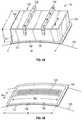
- FIG. 9illustrates an intake area of another engine 302 , similar to the engines illustrated above, which may include a nose cone 304 , a fan having, e.g., a fan blade 306 , and a nacelle 308 radially outside of the fan. Between the fan blade 306 and the hilite 310 , or leading edge of the nacelle 308 , the engine 302 may include a flutter damper, which may include a plurality of chambers 312 , which may inhibit fan flutter by modifying the reflection characteristics of the inlet flow at targeted frequencies.
- a flutter damperwhich may include a plurality of chambers 312 , which may inhibit fan flutter by modifying the reflection characteristics of the inlet flow at targeted frequencies.
- the plurality of chambers 312may be located on the radially inner facing nacelle surface 314 , i.e., the nacelle skin defining the flow path surface, between the hilite 310 and a leading edge 316 of the fan blade 306 .
- the plurality of chambers 312may include a first set of chambers 318 , labeled “A” in FIGS. 9-11 , and a second set of chambers 320 , labeled “B” in FIGS. 9-11 .
- the first set of chambers 318may be configured for peak acoustical energy absorption at a frequency range that is associated with a first fan flutter mode.
- the second set of chambers 320may be configured for peak acoustical energy absorption at a frequency range that is associated with a second fan flutter mode.
- the total volume of dampers in each set 318 , 320provides the damping effect at the targeted frequency for the set.
- the two sets of chambers 318 , 320may be disposed along three axially spaced rows, forming a grid, or checkerboard pattern of chambers.
- the three rowsmay include a first row 322 closest to the hilite 310 , a second row 324 axially aft of the first row 322 , and a third row 326 axially aft of the second row 324 .
- axial spacing between the first row 322 and second row 324may be substantially the same as axial spacing between the second row 324 and the third row 326 .
- circumferential spacing between adjacent flutter dampers 312may be substantially the same around the grid of chambers 312 . Further per a checkerboard pattern, alignment between axially adjacent chambers 312 may be positioned so that center axes of each intersect.
- Chambers from each set 318 , 320may be alternately disposed, axially and circumferentially, in the checkerboard format. This layout provides an intermixed arrangement of chambers 312 .
- the chambers in each set 318 , 320may have an elliptically shaped portion 327 , 328 , for which a minor axis 330 for the first set of chambers 318 and a major axis 332 for the second set of chambers 320 may be disposed along a nacelle axial direction.
- the elliptically shaped portions 327 , 328 of the chambers sets 318 , 320may be spaced from the flow surface by respective cylindrically shaped neck portions 334 , 336 .
- the chambers in the first set of chambers 318may have a greater volume than the chambers in the second set of chambers 320 , to provide desired tuning characteristics.
Landscapes
- Engineering & Computer Science (AREA)
- Chemical & Material Sciences (AREA)
- Combustion & Propulsion (AREA)
- Mechanical Engineering (AREA)
- General Engineering & Computer Science (AREA)
- Physics & Mathematics (AREA)
- Acoustics & Sound (AREA)
- Multimedia (AREA)
- Structures Of Non-Positive Displacement Pumps (AREA)
- Wind Motors (AREA)
Abstract
Description
ftarget=fS,ND+Ω·ND
- fS,ND=frequency of first or second bending mode of fan with ND nodal diameters
1≤ND≤3
ΩMreltip=0.85≤Ω≤ΩMreltip=1.2
ftarget=fS,ND+Ω·ND
- fS,ND=frequency of first or second bending mode of fan with ND nodal diameters
R≥2ρc
−3ρc≤X≤−0.6ρc
is non-dimensional. As indicated, the flutter damper may be located along the
- fS,ND=frequency of first or second bending mode of fan with ND nodal diameters
1≤ND≤3
ΩMreltip=0.85≤Ω≤ΩMreltip=1.2
ftarget=fS,ND+Ω·ND
- fS,ND=frequency of first or second bending mode of fan with ND nodal diameters
Claims (8)
Priority Applications (2)
| Application Number | Priority Date | Filing Date | Title |
|---|---|---|---|
| US15/452,634US10612464B2 (en) | 2017-03-07 | 2017-03-07 | Flutter inhibiting intake for gas turbine propulsion system |
| EP18160554.4AEP3372816B1 (en) | 2017-03-07 | 2018-03-07 | Flutter inhibiting intake for gas turbine propulsion system |
Applications Claiming Priority (1)
| Application Number | Priority Date | Filing Date | Title |
|---|---|---|---|
| US15/452,634US10612464B2 (en) | 2017-03-07 | 2017-03-07 | Flutter inhibiting intake for gas turbine propulsion system |
Publications (2)
| Publication Number | Publication Date |
|---|---|
| US20180258857A1 US20180258857A1 (en) | 2018-09-13 |
| US10612464B2true US10612464B2 (en) | 2020-04-07 |
Family
ID=61616802
Family Applications (1)
| Application Number | Title | Priority Date | Filing Date |
|---|---|---|---|
| US15/452,634Expired - Fee RelatedUS10612464B2 (en) | 2017-03-07 | 2017-03-07 | Flutter inhibiting intake for gas turbine propulsion system |
Country Status (2)
| Country | Link |
|---|---|
| US (1) | US10612464B2 (en) |
| EP (1) | EP3372816B1 (en) |
Cited By (1)
| Publication number | Priority date | Publication date | Assignee | Title |
|---|---|---|---|---|
| US12116932B2 (en) | 2022-08-12 | 2024-10-15 | General Electric Company | Nacelle inlet duct for a ducted fan engine |
Families Citing this family (8)
| Publication number | Priority date | Publication date | Assignee | Title |
|---|---|---|---|---|
| US10415471B2 (en)* | 2016-11-30 | 2019-09-17 | United Technologies Corporation | Variable volume acoustic damper |
| US10415506B2 (en) | 2017-03-07 | 2019-09-17 | United Technologies Corporation | Multi degree of freedom flutter damper |
| US10941708B2 (en)* | 2017-03-07 | 2021-03-09 | Raytheon Technologies Corporation | Acoustically damped gas turbine engine |
| US10539156B2 (en) | 2017-03-07 | 2020-01-21 | United Technologies Corporation | Variable displacement flutter damper for a turbofan engine |
| US10428685B2 (en) | 2017-03-07 | 2019-10-01 | United Technologies Corporation | Flutter inhibiting intake for gas turbine propulsion system |
| US10422280B2 (en) | 2017-03-07 | 2019-09-24 | United Technologies Corporation | Fan flutter suppression system |
| US10619566B2 (en) | 2017-03-07 | 2020-04-14 | United Technologies Corporation | Flutter damper for a turbofan engine |
| DE102020200204A1 (en) | 2020-01-09 | 2021-07-15 | Siemens Aktiengesellschaft | Ceramic resonator for combustion chamber systems and combustion chamber systems |
Citations (68)
| Publication number | Priority date | Publication date | Assignee | Title |
|---|---|---|---|---|
| US3611724A (en) | 1970-01-07 | 1971-10-12 | Gen Electric | Choked inlet noise suppression device for a turbofan engine |
| US3637140A (en) | 1970-09-03 | 1972-01-25 | Goodyear Aerospace Corp | Pneumatically actuated variable area inlet or exhaust nozzle |
| US4084366A (en)* | 1975-11-14 | 1978-04-18 | Haworth Mfg., Inc. | Sound absorbing panel |
| US4235303A (en) | 1978-11-20 | 1980-11-25 | The Boeing Company | Combination bulk absorber-honeycomb acoustic panels |
| US4291080A (en) | 1980-03-31 | 1981-09-22 | Vought Corporation | Sound attenuating structural panel |
| US4313524A (en) | 1980-12-17 | 1982-02-02 | Rohr Industries, Inc. | Bulk acoustic absorber panels for use in high speed gas flow environments |
| GB2090334A (en) | 1980-12-29 | 1982-07-07 | Rolls Royce | Damping flutter of ducted fans |
| US4441578A (en) | 1981-02-02 | 1984-04-10 | Rohr Industries, Inc. | Encapsulated bulk absorber acoustic treatments for aircraft engine application |
| US4452335A (en) | 1982-05-03 | 1984-06-05 | United Technologies Corporation | Sound absorbing structure for a gas turbine engine |
| US4692091A (en) | 1985-09-23 | 1987-09-08 | Ritenour Paul E | Low noise fan |
| US4967550A (en) | 1987-04-28 | 1990-11-06 | Rolls-Royce Plc | Active control of unsteady motion phenomena in turbomachinery |
| US5005353A (en) | 1986-04-28 | 1991-04-09 | Rolls-Royce Plc | Active control of unsteady motion phenomena in turbomachinery |
| US5025888A (en) | 1989-06-26 | 1991-06-25 | Grumman Aerospace Corporation | Acoustic liner |
| WO1992013339A1 (en) | 1991-01-22 | 1992-08-06 | Short Brothers Plc | Noise attenuation panel |
| US5382134A (en) | 1993-11-01 | 1995-01-17 | General Electric Company | Active noise control using noise source having adaptive resonant frequency tuning through stiffness variation |
| US5415522A (en) | 1993-11-01 | 1995-05-16 | General Electric Company | Active noise control using noise source having adaptive resonant frequency tuning through stress variation |
| US5498127A (en) | 1994-11-14 | 1996-03-12 | General Electric Company | Active acoustic liner |
| US5590849A (en) | 1994-12-19 | 1997-01-07 | General Electric Company | Active noise control using an array of plate radiators and acoustic resonators |
| US5594216A (en) | 1994-11-29 | 1997-01-14 | Lockheed Missiles & Space Co., Inc. | Jet engine sound-insulation structure |
| US5919029A (en) | 1996-11-15 | 1999-07-06 | Northrop Grumman Corporation | Noise absorption system having active acoustic liner |
| US5979593A (en) | 1997-01-13 | 1999-11-09 | Hersh Acoustical Engineering, Inc. | Hybrid mode-scattering/sound-absorbing segmented liner system and method |
| US6085865A (en) | 1998-02-26 | 2000-07-11 | Societe Nationale D'etude Et De Construction De Moteurs D'aviation "Snecma" | Soundproofing panel and method of producing said panel |
| US6379110B1 (en) | 1999-02-25 | 2002-04-30 | United Technologies Corporation | Passively driven acoustic jet controlling boundary layers |
| US6634457B2 (en) | 2000-05-26 | 2003-10-21 | Alstom (Switzerland) Ltd | Apparatus for damping acoustic vibrations in a combustor |
| US20040045767A1 (en) | 2000-10-02 | 2004-03-11 | Stuart Byrne | Assembly and method for fan noise reduction from turbofan engines using dynamically adaptive herschel-quincke tubes |
| US6811372B1 (en) | 1999-12-07 | 2004-11-02 | A2 Acoustics Ab | Device at an acoustic liner |
| US6837050B2 (en) | 2001-04-19 | 2005-01-04 | Mitsubishi Heavy Industries, Ltd. | Gas turbine combustor |
| US20050109557A1 (en) | 2003-11-21 | 2005-05-26 | Snecma Moteurs | Soundproofing panel with beads, and a method of manufacture |
| US20050274103A1 (en) | 2004-06-10 | 2005-12-15 | United Technologies Corporation | Gas turbine engine inlet with noise reduction features |
| US20050284690A1 (en) | 2004-06-28 | 2005-12-29 | William Proscia | High admittance acoustic liner |
| US20060037809A1 (en) | 1999-04-20 | 2006-02-23 | Fuller Christopher R | Active/passive distributed absorber for vibration and sound radiation control |
| US20080296431A1 (en) | 2007-04-26 | 2008-12-04 | Ivers Douglas E | Noise controlled turbine engine with aircraft engine adaptive noise control tubes |
| EP2017826A2 (en) | 2007-07-12 | 2009-01-21 | Rolls-Royce plc | An acoustic panel |
| US20090110541A1 (en) | 2007-10-25 | 2009-04-30 | United Technologies Corp. | Vibration Management for Gas Turbine Engines |
| US20090293481A1 (en) | 2005-09-13 | 2009-12-03 | Sven Bethke | Method and Device for Damping Thermoacoustic Oscillations, in Particular in a Gas Turbine |
| US20100206664A1 (en) | 2007-07-12 | 2010-08-19 | Rolls-Royce Plc | Acoustic panel |
| US20100284789A1 (en) | 2009-05-05 | 2010-11-11 | Rolls-Royce Plc | damping assembly |
| US20100284788A1 (en) | 2009-05-05 | 2010-11-11 | Rolls-Royce Plc | Duct wall for a fan of a gas turbine engine |
| US7857093B2 (en) | 2009-03-17 | 2010-12-28 | Spirit Aerosystems, Inc. | Engine inlet deep acoustic liner section |
| US7870929B2 (en) | 2008-04-29 | 2011-01-18 | The Boeing Company | Engine assembly, acoustical liner and associated method of fabrication |
| US20110220433A1 (en) | 2009-02-27 | 2011-09-15 | Mitsubishi Heavy Industries, Ltd. | Combustor and gas turbine having the same |
| US20110266917A1 (en) | 2010-04-30 | 2011-11-03 | Thomas Metzger | Guided Bulk Acoustic Wave Device Having Reduced Height and Method for Manufacturing |
| US20120124965A1 (en) | 2008-03-05 | 2012-05-24 | Grabowski Zbigniew M | Variable area fan nozzle fan flutter management system |
| EP2466095A2 (en) | 2010-12-15 | 2012-06-20 | Rolls-Royce plc | An acoustic liner |
| US8434995B2 (en) | 2009-05-05 | 2013-05-07 | Rolls-Royce Plc | Duct wall for a fan of a gas turbine engine |
| US8578697B2 (en) | 2008-05-06 | 2013-11-12 | Rolls-Royce Plc | Fan section |
| US20140169935A1 (en) | 2012-12-19 | 2014-06-19 | United Technologies Corporation | Lightweight shrouded fan blade |
| US20140233769A1 (en) | 2011-09-28 | 2014-08-21 | Eads Deutschland Gmbh | Diaphragm arrangement for generating sound |
| WO2014189572A2 (en) | 2013-02-26 | 2014-11-27 | United Technologies Corporation | Acoustic treatment to mitigate fan noise |
| US20140366554A1 (en) | 2010-07-27 | 2014-12-18 | United Technologies Corporation | Cross reference to related applications |
| US8931588B2 (en) | 2012-05-31 | 2015-01-13 | Rolls-Royce Plc | Acoustic panel |
| US9181875B2 (en) | 2011-04-01 | 2015-11-10 | Alstom Technology Ltd | Gas turbine air intake manifold controllably changing a mechnical rigidity of the walls of said intake manifold |
| US20160076453A1 (en) | 2014-09-12 | 2016-03-17 | Rolls-Royce Deutschland Ltd & Co Kg | Sound-damping arrangement for an engine nacelle and engine nacelle comprising such an arrangement |
| US20160194968A1 (en) | 2013-08-23 | 2016-07-07 | United Technologies Corporation | High performance convergent divergent nozzle |
| US20160298847A1 (en) | 2015-04-07 | 2016-10-13 | General Electric Company | System and method for tuning resonators |
| US9546558B2 (en) | 2010-07-08 | 2017-01-17 | Siemens Energy, Inc. | Damping resonator with impingement cooling |
| US20170022826A1 (en) | 2015-07-22 | 2017-01-26 | Rolls-Royce Plc | Gas turbine engine |
| US20170058780A1 (en)* | 2015-08-25 | 2017-03-02 | General Electric Company | System for suppressing acoustic noise within a gas turbine combustor |
| EP3187713A1 (en) | 2015-12-30 | 2017-07-05 | General Electric Company | Acoustic liner for gas turbine engine components |
| EP3333402A1 (en) | 2016-11-30 | 2018-06-13 | United Technologies Corporation | Variable volume acoustic damper |
| US20180209345A1 (en) | 2017-01-20 | 2018-07-26 | Rolls-Royce Corporation | Piezoelectric vibratory control for static engine components |
| US10066548B2 (en)* | 2013-03-15 | 2018-09-04 | United Technologies Corporation | Acoustic liner with varied properties |
| US20180258854A1 (en) | 2017-03-07 | 2018-09-13 | United Technologies Corporation | Fan flutter suppression system |
| US20180258788A1 (en) | 2017-03-07 | 2018-09-13 | United Technologies Corporation | Flutter inhibiting intake for gas turbine propulsion system |
| US20180258855A1 (en) | 2017-03-07 | 2018-09-13 | United Technologies Corporation | Flutter damper for a turbofan engine |
| US20180258856A1 (en) | 2017-03-07 | 2018-09-13 | United Technologies Corporation | Acoustically damped gas turbine engine |
| US20180258956A1 (en) | 2017-03-07 | 2018-09-13 | United Technologies Corporation | Variable displacement flutter damper for a turbofan engine |
| US20180258955A1 (en) | 2017-03-07 | 2018-09-13 | United Technologies Corporation | Multi degree of freedom flutter damper |
- 2017
- 2017-03-07USUS15/452,634patent/US10612464B2/ennot_activeExpired - Fee Related
- 2018
- 2018-03-07EPEP18160554.4Apatent/EP3372816B1/enactiveActive
Patent Citations (72)
| Publication number | Priority date | Publication date | Assignee | Title |
|---|---|---|---|---|
| US3611724A (en) | 1970-01-07 | 1971-10-12 | Gen Electric | Choked inlet noise suppression device for a turbofan engine |
| US3637140A (en) | 1970-09-03 | 1972-01-25 | Goodyear Aerospace Corp | Pneumatically actuated variable area inlet or exhaust nozzle |
| US4084366A (en)* | 1975-11-14 | 1978-04-18 | Haworth Mfg., Inc. | Sound absorbing panel |
| US4235303A (en) | 1978-11-20 | 1980-11-25 | The Boeing Company | Combination bulk absorber-honeycomb acoustic panels |
| US4291080A (en) | 1980-03-31 | 1981-09-22 | Vought Corporation | Sound attenuating structural panel |
| US4313524A (en) | 1980-12-17 | 1982-02-02 | Rohr Industries, Inc. | Bulk acoustic absorber panels for use in high speed gas flow environments |
| GB2090334A (en) | 1980-12-29 | 1982-07-07 | Rolls Royce | Damping flutter of ducted fans |
| US4531362A (en) | 1980-12-29 | 1985-07-30 | Rolls-Royce Limited | Aerodynamic damping of vibrations in rotor blades |
| US4441578A (en) | 1981-02-02 | 1984-04-10 | Rohr Industries, Inc. | Encapsulated bulk absorber acoustic treatments for aircraft engine application |
| US4452335A (en) | 1982-05-03 | 1984-06-05 | United Technologies Corporation | Sound absorbing structure for a gas turbine engine |
| US4692091A (en) | 1985-09-23 | 1987-09-08 | Ritenour Paul E | Low noise fan |
| US5005353A (en) | 1986-04-28 | 1991-04-09 | Rolls-Royce Plc | Active control of unsteady motion phenomena in turbomachinery |
| US4967550A (en) | 1987-04-28 | 1990-11-06 | Rolls-Royce Plc | Active control of unsteady motion phenomena in turbomachinery |
| US5025888A (en) | 1989-06-26 | 1991-06-25 | Grumman Aerospace Corporation | Acoustic liner |
| WO1992013339A1 (en) | 1991-01-22 | 1992-08-06 | Short Brothers Plc | Noise attenuation panel |
| US5415522A (en) | 1993-11-01 | 1995-05-16 | General Electric Company | Active noise control using noise source having adaptive resonant frequency tuning through stress variation |
| US5382134A (en) | 1993-11-01 | 1995-01-17 | General Electric Company | Active noise control using noise source having adaptive resonant frequency tuning through stiffness variation |
| US5498127A (en) | 1994-11-14 | 1996-03-12 | General Electric Company | Active acoustic liner |
| US5594216A (en) | 1994-11-29 | 1997-01-14 | Lockheed Missiles & Space Co., Inc. | Jet engine sound-insulation structure |
| US5590849A (en) | 1994-12-19 | 1997-01-07 | General Electric Company | Active noise control using an array of plate radiators and acoustic resonators |
| US5919029A (en) | 1996-11-15 | 1999-07-06 | Northrop Grumman Corporation | Noise absorption system having active acoustic liner |
| US5979593A (en) | 1997-01-13 | 1999-11-09 | Hersh Acoustical Engineering, Inc. | Hybrid mode-scattering/sound-absorbing segmented liner system and method |
| US6085865A (en) | 1998-02-26 | 2000-07-11 | Societe Nationale D'etude Et De Construction De Moteurs D'aviation "Snecma" | Soundproofing panel and method of producing said panel |
| US6379110B1 (en) | 1999-02-25 | 2002-04-30 | United Technologies Corporation | Passively driven acoustic jet controlling boundary layers |
| US20060037809A1 (en) | 1999-04-20 | 2006-02-23 | Fuller Christopher R | Active/passive distributed absorber for vibration and sound radiation control |
| US6811372B1 (en) | 1999-12-07 | 2004-11-02 | A2 Acoustics Ab | Device at an acoustic liner |
| US6634457B2 (en) | 2000-05-26 | 2003-10-21 | Alstom (Switzerland) Ltd | Apparatus for damping acoustic vibrations in a combustor |
| US20040045767A1 (en) | 2000-10-02 | 2004-03-11 | Stuart Byrne | Assembly and method for fan noise reduction from turbofan engines using dynamically adaptive herschel-quincke tubes |
| US6837050B2 (en) | 2001-04-19 | 2005-01-04 | Mitsubishi Heavy Industries, Ltd. | Gas turbine combustor |
| US20050109557A1 (en) | 2003-11-21 | 2005-05-26 | Snecma Moteurs | Soundproofing panel with beads, and a method of manufacture |
| US20050274103A1 (en) | 2004-06-10 | 2005-12-15 | United Technologies Corporation | Gas turbine engine inlet with noise reduction features |
| US20050284690A1 (en) | 2004-06-28 | 2005-12-29 | William Proscia | High admittance acoustic liner |
| US20090293481A1 (en) | 2005-09-13 | 2009-12-03 | Sven Bethke | Method and Device for Damping Thermoacoustic Oscillations, in Particular in a Gas Turbine |
| US20080296431A1 (en) | 2007-04-26 | 2008-12-04 | Ivers Douglas E | Noise controlled turbine engine with aircraft engine adaptive noise control tubes |
| US20100206664A1 (en) | 2007-07-12 | 2010-08-19 | Rolls-Royce Plc | Acoustic panel |
| EP2017826A2 (en) | 2007-07-12 | 2009-01-21 | Rolls-Royce plc | An acoustic panel |
| US20090110541A1 (en) | 2007-10-25 | 2009-04-30 | United Technologies Corp. | Vibration Management for Gas Turbine Engines |
| US20120124965A1 (en) | 2008-03-05 | 2012-05-24 | Grabowski Zbigniew M | Variable area fan nozzle fan flutter management system |
| US7870929B2 (en) | 2008-04-29 | 2011-01-18 | The Boeing Company | Engine assembly, acoustical liner and associated method of fabrication |
| US8578697B2 (en) | 2008-05-06 | 2013-11-12 | Rolls-Royce Plc | Fan section |
| US20110220433A1 (en) | 2009-02-27 | 2011-09-15 | Mitsubishi Heavy Industries, Ltd. | Combustor and gas turbine having the same |
| US7857093B2 (en) | 2009-03-17 | 2010-12-28 | Spirit Aerosystems, Inc. | Engine inlet deep acoustic liner section |
| EP2251535A2 (en) | 2009-05-05 | 2010-11-17 | Rolls-Royce plc | A damping assembly |
| EP2256302A1 (en) | 2009-05-05 | 2010-12-01 | Rolls-Royce plc | A duct wall for a fan of a gas turbine engine |
| US9097179B2 (en) | 2009-05-05 | 2015-08-04 | Rolls-Royce Plc | Damping assembly |
| US8434995B2 (en) | 2009-05-05 | 2013-05-07 | Rolls-Royce Plc | Duct wall for a fan of a gas turbine engine |
| US20100284788A1 (en) | 2009-05-05 | 2010-11-11 | Rolls-Royce Plc | Duct wall for a fan of a gas turbine engine |
| US20100284789A1 (en) | 2009-05-05 | 2010-11-11 | Rolls-Royce Plc | damping assembly |
| US20110266917A1 (en) | 2010-04-30 | 2011-11-03 | Thomas Metzger | Guided Bulk Acoustic Wave Device Having Reduced Height and Method for Manufacturing |
| US9546558B2 (en) | 2010-07-08 | 2017-01-17 | Siemens Energy, Inc. | Damping resonator with impingement cooling |
| US20140366554A1 (en) | 2010-07-27 | 2014-12-18 | United Technologies Corporation | Cross reference to related applications |
| EP2466095A2 (en) | 2010-12-15 | 2012-06-20 | Rolls-Royce plc | An acoustic liner |
| US9181875B2 (en) | 2011-04-01 | 2015-11-10 | Alstom Technology Ltd | Gas turbine air intake manifold controllably changing a mechnical rigidity of the walls of said intake manifold |
| US20140233769A1 (en) | 2011-09-28 | 2014-08-21 | Eads Deutschland Gmbh | Diaphragm arrangement for generating sound |
| US8931588B2 (en) | 2012-05-31 | 2015-01-13 | Rolls-Royce Plc | Acoustic panel |
| US20140169935A1 (en) | 2012-12-19 | 2014-06-19 | United Technologies Corporation | Lightweight shrouded fan blade |
| WO2014189572A2 (en) | 2013-02-26 | 2014-11-27 | United Technologies Corporation | Acoustic treatment to mitigate fan noise |
| US10066548B2 (en)* | 2013-03-15 | 2018-09-04 | United Technologies Corporation | Acoustic liner with varied properties |
| US20160194968A1 (en) | 2013-08-23 | 2016-07-07 | United Technologies Corporation | High performance convergent divergent nozzle |
| US20160076453A1 (en) | 2014-09-12 | 2016-03-17 | Rolls-Royce Deutschland Ltd & Co Kg | Sound-damping arrangement for an engine nacelle and engine nacelle comprising such an arrangement |
| US20160298847A1 (en) | 2015-04-07 | 2016-10-13 | General Electric Company | System and method for tuning resonators |
| US20170022826A1 (en) | 2015-07-22 | 2017-01-26 | Rolls-Royce Plc | Gas turbine engine |
| US20170058780A1 (en)* | 2015-08-25 | 2017-03-02 | General Electric Company | System for suppressing acoustic noise within a gas turbine combustor |
| EP3187713A1 (en) | 2015-12-30 | 2017-07-05 | General Electric Company | Acoustic liner for gas turbine engine components |
| EP3333402A1 (en) | 2016-11-30 | 2018-06-13 | United Technologies Corporation | Variable volume acoustic damper |
| US20180209345A1 (en) | 2017-01-20 | 2018-07-26 | Rolls-Royce Corporation | Piezoelectric vibratory control for static engine components |
| US20180258854A1 (en) | 2017-03-07 | 2018-09-13 | United Technologies Corporation | Fan flutter suppression system |
| US20180258788A1 (en) | 2017-03-07 | 2018-09-13 | United Technologies Corporation | Flutter inhibiting intake for gas turbine propulsion system |
| US20180258855A1 (en) | 2017-03-07 | 2018-09-13 | United Technologies Corporation | Flutter damper for a turbofan engine |
| US20180258856A1 (en) | 2017-03-07 | 2018-09-13 | United Technologies Corporation | Acoustically damped gas turbine engine |
| US20180258956A1 (en) | 2017-03-07 | 2018-09-13 | United Technologies Corporation | Variable displacement flutter damper for a turbofan engine |
| US20180258955A1 (en) | 2017-03-07 | 2018-09-13 | United Technologies Corporation | Multi degree of freedom flutter damper |
Non-Patent Citations (8)
| Title |
|---|
| European Search Report for Application No. 18160541.1-1007; dated Jul. 19, 2018; 6 pgs. |
| European Search Report for Application No. 18160550.2-1007; dated Jul. 19, 2018; 7 pgs. |
| European Search Report for Application No. 18160552.8-1007; dated Jul. 3, 2018; 12 pgs. |
| European Search Report for Application No. 18160554.4-1007; dated Jul. 19, 2018; 7 pgs. |
| European Search Report for Application No. 18160556.9-1007; dated Jul. 24, 2018; 7 pgs. |
| European Search Report for Application No. 18160559.3-1007; dated Jul. 24, 2018; 7 pgs. |
| European Search Report for Application No. 18160561.9; dated Jul. 4, 2018; 10 pgs. |
| Mustafi, Prateek; "Improved Turbofan Intake Liner Design and Optimization"; Feb. 12, 2013; Theisis paper Faculty of Engineering and the Enviroment, Institute of Sound and Vibration Research; Univeristy of Southampton; 196 pages. |
Cited By (1)
| Publication number | Priority date | Publication date | Assignee | Title |
|---|---|---|---|---|
| US12116932B2 (en) | 2022-08-12 | 2024-10-15 | General Electric Company | Nacelle inlet duct for a ducted fan engine |
Also Published As
| Publication number | Publication date |
|---|---|
| EP3372816A1 (en) | 2018-09-12 |
| EP3372816B1 (en) | 2021-11-03 |
| US20180258857A1 (en) | 2018-09-13 |
Similar Documents
| Publication | Publication Date | Title |
|---|---|---|
| US10612464B2 (en) | Flutter inhibiting intake for gas turbine propulsion system | |
| US10415506B2 (en) | Multi degree of freedom flutter damper | |
| US10428685B2 (en) | Flutter inhibiting intake for gas turbine propulsion system | |
| EP3372807B1 (en) | Flutter dampening acoustic liner for a turbofan engine | |
| EP3372815B1 (en) | Fan flutter suppression system | |
| EP3372788B1 (en) | Acoustically damped gas turbine engine | |
| EP3372813B1 (en) | Multi degree of freedom flutter damper | |
| EP3869499B1 (en) | Acoustic liner with non-uniform volumetric distribution | |
| US10619566B2 (en) | Flutter damper for a turbofan engine | |
| EP3372814B1 (en) | Asymmetric multi degree of freedom flutter damper | |
| US10428765B2 (en) | Asymmetric multi degree of freedom flutter damper | |
| US10539156B2 (en) | Variable displacement flutter damper for a turbofan engine | |
| EP2961959B1 (en) | Acoustic treatment to mitigate fan noise | |
| US10371173B2 (en) | Liner for a gas turbine engine |
Legal Events
| Date | Code | Title | Description |
|---|---|---|---|
| AS | Assignment | Owner name:UNITED TECHNOLOGIES CORPORATION, CONNECTICUT Free format text:ASSIGNMENT OF ASSIGNORS INTEREST;ASSIGNORS:PRASAD, DILIP;MORIN, BRUCE L.;SIGNING DATES FROM 20170328 TO 20170330;REEL/FRAME:044657/0369 | |
| STPP | Information on status: patent application and granting procedure in general | Free format text:NON FINAL ACTION MAILED | |
| STPP | Information on status: patent application and granting procedure in general | Free format text:RESPONSE TO NON-FINAL OFFICE ACTION ENTERED AND FORWARDED TO EXAMINER | |
| STPP | Information on status: patent application and granting procedure in general | Free format text:NOTICE OF ALLOWANCE MAILED -- APPLICATION RECEIVED IN OFFICE OF PUBLICATIONS | |
| ZAAA | Notice of allowance and fees due | Free format text:ORIGINAL CODE: NOA | |
| ZAAB | Notice of allowance mailed | Free format text:ORIGINAL CODE: MN/=. | |
| STPP | Information on status: patent application and granting procedure in general | Free format text:NOTICE OF ALLOWANCE MAILED -- APPLICATION RECEIVED IN OFFICE OF PUBLICATIONS | |
| ZAAA | Notice of allowance and fees due | Free format text:ORIGINAL CODE: NOA | |
| STPP | Information on status: patent application and granting procedure in general | Free format text:NOTICE OF ALLOWANCE MAILED -- APPLICATION RECEIVED IN OFFICE OF PUBLICATIONS | |
| STPP | Information on status: patent application and granting procedure in general | Free format text:PUBLICATIONS -- ISSUE FEE PAYMENT RECEIVED | |
| STPP | Information on status: patent application and granting procedure in general | Free format text:PUBLICATIONS -- ISSUE FEE PAYMENT VERIFIED | |
| STPP | Information on status: patent application and granting procedure in general | Free format text:AWAITING TC RESP., ISSUE FEE NOT PAID | |
| ZAAA | Notice of allowance and fees due | Free format text:ORIGINAL CODE: NOA | |
| STCF | Information on status: patent grant | Free format text:PATENTED CASE | |
| AS | Assignment | Owner name:RAYTHEON TECHNOLOGIES CORPORATION, MASSACHUSETTS Free format text:CHANGE OF NAME;ASSIGNOR:UNITED TECHNOLOGIES CORPORATION;REEL/FRAME:054062/0001 Effective date:20200403 | |
| AS | Assignment | Owner name:RAYTHEON TECHNOLOGIES CORPORATION, CONNECTICUT Free format text:CORRECTIVE ASSIGNMENT TO CORRECT THE AND REMOVE PATENT APPLICATION NUMBER 11886281 AND ADD PATENT APPLICATION NUMBER 14846874. TO CORRECT THE RECEIVING PARTY ADDRESS PREVIOUSLY RECORDED AT REEL: 054062 FRAME: 0001. ASSIGNOR(S) HEREBY CONFIRMS THE CHANGE OF ADDRESS;ASSIGNOR:UNITED TECHNOLOGIES CORPORATION;REEL/FRAME:055659/0001 Effective date:20200403 | |
| AS | Assignment | Owner name:RTX CORPORATION, CONNECTICUT Free format text:CHANGE OF NAME;ASSIGNOR:RAYTHEON TECHNOLOGIES CORPORATION;REEL/FRAME:064402/0837 Effective date:20230714 | |
| FEPP | Fee payment procedure | Free format text:MAINTENANCE FEE REMINDER MAILED (ORIGINAL EVENT CODE: REM.); ENTITY STATUS OF PATENT OWNER: LARGE ENTITY | |
| LAPS | Lapse for failure to pay maintenance fees | Free format text:PATENT EXPIRED FOR FAILURE TO PAY MAINTENANCE FEES (ORIGINAL EVENT CODE: EXP.); ENTITY STATUS OF PATENT OWNER: LARGE ENTITY | |
| STCH | Information on status: patent discontinuation | Free format text:PATENT EXPIRED DUE TO NONPAYMENT OF MAINTENANCE FEES UNDER 37 CFR 1.362 | |
| FP | Lapsed due to failure to pay maintenance fee | Effective date:20240407 |