US10611391B1 - Mobile support and storage system for a medical device - Google Patents
Mobile support and storage system for a medical deviceDownload PDFInfo
- Publication number
- US10611391B1 US10611391B1US16/152,811US201816152811AUS10611391B1US 10611391 B1US10611391 B1US 10611391B1US 201816152811 AUS201816152811 AUS 201816152811AUS 10611391 B1US10611391 B1US 10611391B1
- Authority
- US
- United States
- Prior art keywords
- carriage
- arm
- housing
- mobile support
- support system
- Prior art date
- Legal status (The legal status is an assumption and is not a legal conclusion. Google has not performed a legal analysis and makes no representation as to the accuracy of the status listed.)
- Active
Links
- 230000007246mechanismEffects0.000claimsabstractdescription37
- 230000005484gravityEffects0.000description4
- 238000000034methodMethods0.000description4
- 238000009434installationMethods0.000description3
- 238000010586diagramMethods0.000description2
- 238000012986modificationMethods0.000description1
- 230000004048modificationEffects0.000description1
Images


Classifications
- B—PERFORMING OPERATIONS; TRANSPORTING
- B62—LAND VEHICLES FOR TRAVELLING OTHERWISE THAN ON RAILS
- B62B—HAND-PROPELLED VEHICLES, e.g. HAND CARTS OR PERAMBULATORS; SLEDGES
- B62B3/00—Hand carts having more than one axis carrying transport wheels; Steering devices therefor; Equipment therefor
- B62B3/04—Hand carts having more than one axis carrying transport wheels; Steering devices therefor; Equipment therefor involving means for grappling or securing in place objects to be carried; Loading or unloading equipment
- A—HUMAN NECESSITIES
- A61—MEDICAL OR VETERINARY SCIENCE; HYGIENE
- A61G—TRANSPORT, PERSONAL CONVEYANCES, OR ACCOMMODATION SPECIALLY ADAPTED FOR PATIENTS OR DISABLED PERSONS; OPERATING TABLES OR CHAIRS; CHAIRS FOR DENTISTRY; FUNERAL DEVICES
- A61G12/00—Accommodation for nursing, e.g. in hospitals, not covered by groups A61G1/00 - A61G11/00, e.g. trolleys for transport of medicaments or food; Prescription lists
- A61G12/001—Trolleys for transport of medicaments, food, linen, nursing supplies
- A—HUMAN NECESSITIES
- A61—MEDICAL OR VETERINARY SCIENCE; HYGIENE
- A61B—DIAGNOSIS; SURGERY; IDENTIFICATION
- A61B50/00—Containers, covers, furniture or holders specially adapted for surgical or diagnostic appliances or instruments, e.g. sterile covers
- A61B50/10—Furniture specially adapted for surgical or diagnostic appliances or instruments
- A61B50/13—Trolleys, e.g. carts
- A—HUMAN NECESSITIES
- A61—MEDICAL OR VETERINARY SCIENCE; HYGIENE
- A61B—DIAGNOSIS; SURGERY; IDENTIFICATION
- A61B90/00—Instruments, implements or accessories specially adapted for surgery or diagnosis and not covered by any of the groups A61B1/00 - A61B50/00, e.g. for luxation treatment or for protecting wound edges
- A61B90/50—Supports for surgical instruments, e.g. articulated arms
- A61B90/57—Accessory clamps
- A—HUMAN NECESSITIES
- A61—MEDICAL OR VETERINARY SCIENCE; HYGIENE
- A61G—TRANSPORT, PERSONAL CONVEYANCES, OR ACCOMMODATION SPECIALLY ADAPTED FOR PATIENTS OR DISABLED PERSONS; OPERATING TABLES OR CHAIRS; CHAIRS FOR DENTISTRY; FUNERAL DEVICES
- A61G7/00—Beds specially adapted for nursing; Devices for lifting patients or disabled persons
- A61G7/05—Parts, details or accessories of beds
- A61G7/0507—Side-rails
- A61G7/0524—Side-rails characterised by integrated accessories, e.g. bed control means, nurse call or reading lights
- B—PERFORMING OPERATIONS; TRANSPORTING
- B62—LAND VEHICLES FOR TRAVELLING OTHERWISE THAN ON RAILS
- B62B—HAND-PROPELLED VEHICLES, e.g. HAND CARTS OR PERAMBULATORS; SLEDGES
- B62B3/00—Hand carts having more than one axis carrying transport wheels; Steering devices therefor; Equipment therefor
- B62B3/10—Hand carts having more than one axis carrying transport wheels; Steering devices therefor; Equipment therefor characterised by supports specially adapted to objects of definite shape
- B—PERFORMING OPERATIONS; TRANSPORTING
- B62—LAND VEHICLES FOR TRAVELLING OTHERWISE THAN ON RAILS
- B62B—HAND-PROPELLED VEHICLES, e.g. HAND CARTS OR PERAMBULATORS; SLEDGES
- B62B5/00—Accessories or details specially adapted for hand carts
- B62B5/04—Braking mechanisms; Locking devices against movement
- B62B5/0433—Braking mechanisms; Locking devices against movement foot operated
- B—PERFORMING OPERATIONS; TRANSPORTING
- B62—LAND VEHICLES FOR TRAVELLING OTHERWISE THAN ON RAILS
- B62B—HAND-PROPELLED VEHICLES, e.g. HAND CARTS OR PERAMBULATORS; SLEDGES
- B62B5/00—Accessories or details specially adapted for hand carts
- B62B5/04—Braking mechanisms; Locking devices against movement
- B62B5/049—Braking mechanisms; Locking devices against movement locking against movement by contacting the floor or a wall
- A—HUMAN NECESSITIES
- A61—MEDICAL OR VETERINARY SCIENCE; HYGIENE
- A61B—DIAGNOSIS; SURGERY; IDENTIFICATION
- A61B90/00—Instruments, implements or accessories specially adapted for surgery or diagnosis and not covered by any of the groups A61B1/00 - A61B50/00, e.g. for luxation treatment or for protecting wound edges
- A61B90/50—Supports for surgical instruments, e.g. articulated arms
- A61B2090/508—Supports for surgical instruments, e.g. articulated arms with releasable brake mechanisms
- A—HUMAN NECESSITIES
- A61—MEDICAL OR VETERINARY SCIENCE; HYGIENE
- A61B—DIAGNOSIS; SURGERY; IDENTIFICATION
- A61B90/00—Instruments, implements or accessories specially adapted for surgery or diagnosis and not covered by any of the groups A61B1/00 - A61B50/00, e.g. for luxation treatment or for protecting wound edges
- A61B90/50—Supports for surgical instruments, e.g. articulated arms
- A61B90/57—Accessory clamps
- A61B2090/571—Accessory clamps for clamping a support arm to a bed or other supports
- A—HUMAN NECESSITIES
- A61—MEDICAL OR VETERINARY SCIENCE; HYGIENE
- A61G—TRANSPORT, PERSONAL CONVEYANCES, OR ACCOMMODATION SPECIALLY ADAPTED FOR PATIENTS OR DISABLED PERSONS; OPERATING TABLES OR CHAIRS; CHAIRS FOR DENTISTRY; FUNERAL DEVICES
- A61G13/00—Operating tables; Auxiliary appliances therefor
- A61G13/10—Parts, details or accessories
- A61G13/101—Clamping means for connecting accessories to the operating table
- B—PERFORMING OPERATIONS; TRANSPORTING
- B62—LAND VEHICLES FOR TRAVELLING OTHERWISE THAN ON RAILS
- B62B—HAND-PROPELLED VEHICLES, e.g. HAND CARTS OR PERAMBULATORS; SLEDGES
- B62B2202/00—Indexing codes relating to type or characteristics of transported articles
- B—PERFORMING OPERATIONS; TRANSPORTING
- B62—LAND VEHICLES FOR TRAVELLING OTHERWISE THAN ON RAILS
- B62B—HAND-PROPELLED VEHICLES, e.g. HAND CARTS OR PERAMBULATORS; SLEDGES
- B62B2203/00—Grasping, holding, supporting the objects
- B62B2203/20—Grasping, holding, supporting the objects using forks or tines
- B62B2203/24—Changing the position of the fork or supports
Definitions
- the present inventionrelates generally to the field of medical devices and more particularly to a mobile support and storage system for a medical device.
- Medical beds or tables used in hospitals, clinics, doctor offices or other medical environmentsmay include a rail operatively secured to the bed for supporting various medical devices. There may be circumstances where it is desirable to remove the medical device from the table between procedures. However, such devices may be heavy and manually installing and removing the medical devices can be difficult.
- a mobile support system for a medical device having an arm with a baseincludes a body comprising a housing having a top surface, a first end and a second end and a carriage positioned within the housing, a mechanism coupled to the carriage and configured to cause movement of the carriage, a set of wheels coupled to the housing, a support arm coupled to the carriage and extending vertically upward from the top surface of the housing, the support arm configured to support the arm of the medical device, a mounting block coupled to the carriage proximate to the support arm, the mounting block configured to couple with the base of the arm of the medical device, a first rail detect guide located on the top surface at the second end of the housing and a second rail detect guide located on the top surface at the second end of the housing, wherein the first rail detect guide and the second rail detect guide are configured to unlock the mechanism used to cause movement of the carriage when contact is made between the first rail detect guide and the second rail detect guide and a surface.
- a mobile support system for a medical device having an arm with a baseincludes a body comprising a housing having a top surface and a carriage positioned within the housing, a mechanism coupled to the carriage and configured to cause movement of the carriage, a set of wheels coupled to the housing, a floor brake coupled to the housing, the floor brake configured to be actuated in response to movement of the carriage, a support arm coupled to the carriage and extending vertically upward from the top surface of the housing, the support arm configured to support the arm of the medical device and a mounting block coupled to the carriage proximate to the support arm, the mounting block configured to couple with the base of the arm of the medical device.
- a mobile support systemincludes a medical device having an arm with a base, the base comprising a rail detect lever configured to be actuated when contact is made between the rail detect lever and a surface, a body comprising a housing and a carriage positioned within the housing, a support arm coupled to the carriage and extending vertically upward from the housing, the support arm configured to support the arm of the medical device and a mounting block coupled to the carriage proximate to the support arm, the mounting block configured to couple with the base of the arm of the medical device.
- a mobile support systemincludes a medical device having an arm with a base, the base comprising a brake and a brake release coupled to the brake, a body comprising a housing and a carriage positioned within the housing, a support arm coupled to the carriage and extending vertically upward from the housing, the support arm configured to support the arm of the medical device and a mounting block coupled to the carriage proximate to the support arm, the mounting block configured to couple with the base of the arm of the medical device, the mounting block configured to actuate the brake release when the mounting block engages the base of the arm.
- a mobile support systemincludes a medical device having an arm with a base, the base includes a first roller, a first roller shaft coupled to the first roller, a first locking mechanism coupled to the first roller shaft, a second roller, a second roller shaft coupled to the second roller and a second locking mechanism coupled to the second roller shaft.
- the mobile support systemfurther includes a body comprising a housing and a carriage positioned within the housing, a support arm coupled to the carriage and extending vertically upward from the housing, the support arm configured to support the arm of the medical device and a mounting block coupled to the carriage proximate to the support arm, the mounting block configured to couple with the base of the arm of the medical device, the mounting block comprising a set of pins configured to couple with the first roller shaft and the second roller shaft, wherein the first locking mechanism and the second locking mechanism are configured to lock the first roller shaft and the second roller shaft, respectively, when the set of pins of the mounting block are disengaged from the first roller shaft and the second roller shaft.
- FIG. 1is a schematic diagram of an exemplary medical bed or table with a medical device mounted to the medical bed or table in accordance with an embodiment
- FIG. 2is a perspective view of a mobile support system in a first position in accordance with an embodiment
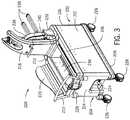
- FIG. 3is a perspective view of a mobile support system in a second position in accordance with an embodiment
- FIG. 4is a perspective front view of a portion of a mobile support system in accordance with an embodiment
- FIG. 5is a perspective view of a mobile support system in a first position in accordance with an embodiment
- FIG. 6is a perspective view of a mobile support system with a raised carriage at the first position in accordance with an embodiment
- FIG. 7is a perspective view of a mobile support system in a second position in accordance with an embodiment
- FIG. 8is a perspective view of a mobile support system with a lowered carriage at the second position in accordance with an embodiment
- FIG. 9is a perspective view looking upward towards a bottom portion of a base of an arm of a medical device in accordance with an embodiment
- FIG. 10is a side view of a mounting block in a carriage of a mobile support system in accordance with an embodiment
- FIG. 11is a front view of a mobile support system in accordance with an embodiment
- FIG. 12is a perspective view of a mobile support system with a lowered carriage at the second position in accordance with an embodiment
- FIG. 13is a perspective view of a mobile support system in a second position in accordance with an embodiment
- FIG. 14is a perspective view of a mobile support system with a raised carriage at the first position in accordance with an embodiment
- FIG. 15is a perspective view of a mobile support system in a first position in accordance with an embodiment.
- the vertical directionis the direction parallel to the direction of gravity and the horizontal direction is a direction generally perpendicular to the direction of gravity.
- the term upwardwill be a vertical direction opposite the direction of the force of gravity and the term downward will be a vertical direction in the direction of gravity.
- FIG. 1is a schematic diagram of an exemplary medical bed or table with a medical device mounted to the medical bed or table in accordance with an embodiment.
- a medical bed or table 100includes a rail 102 .
- a medical device 104may be mounted to the table 100 using the rail 102 .
- the medical device 104includes an arm 106 that has a lower portion 108 and is used to support an instrument or system used in a medical procedure.
- the arm 106may include an articulated upper portion 110 .
- the arm 106also includes a base 112 that is configured to mount and secure the medical device 104 to the rail 102 .
- the instrument or system supported by the arm 106may be, for example, a robotic catheter system, an IV pole, a monitor, a contrast solution injector, etc.
- an exemplary robotic catheter system 114is shown attached to the arm 106 .
- FIG. 2is a perspective view of a mobile support system in a first position in accordance with an embodiment
- FIG. 3is a perspective view of a mobile support system in a second position in accordance with an embodiment.
- a mobile support 200e.g., a cart
- a body 202having a housing 204 .
- the housing 204includes a top surface 206 , a bottom surface 208 , a first side 210 , a second side 212 , a first end 214 and a second end 216 . While a rectangular or cube shaped housing is shown, in other embodiments, the housing of the mobile support system 200 may have other shapes such as a cylinder and the housing may be a closed or open frame. A set of wheels 226 are attached to the bottom surface 208 of the housing 204 .
- a floor brake 242is also positioned on the bottom surface and is configured to be in a raised position when the mobile support 200 is used to transport and store the medical device and in a lowered position when the mobile support 200 is used to install the medical device on the rail of a bed or table and to remove the medical device from the rail of a bed or table as discussed further below.
- the first end 214 of the housingincludes a handle 222 , a foot pedal 224 and a button 228 .
- a support arm 218is positioned in a carriage 234 inside the housing 204 .
- the support arm 218is located in a first position proximate the first end 214 of the housing 204 .
- the first position shown in FIG. 2may be used when the medical device is not in use and is being stored.
- the support arm 218is located at a second position proximate the second end 216 of the housing 204 .
- the second position shown in FIG. 3may be used when the mobile support 200 is being used to install the medical device on or remove the medical device from the bed or table.
- a lower portion 236 of an arm of a medical devicemay be positioned in and adjacent to the support arm 218 .
- the support arm 218may include a mounting block 241 (shown in FIG. 4 ) at a lower end of the support arm 218 proximate the top surface 206 of the housing and the carriage 234 .
- the lower portion 236 of the arm of the medical deviceincludes a base 240 that is configured to engage the mounting block 241 when the medical device is mounted on the cart. In embodiments described below, the base 240 and mounting block 241 interface vertically. The base 240 is also configured to engage the rail of a bed or table when the medical device is mounted to the bed or table.
- the lower portion 236 of the armalso includes a set of feet 238 that may be located on top of the bed or table and under, for example, a mattress when the medical device is mounted and secured to the bed or table. The feet 238 may be used to apply load directly onto the table surface in addition to a rail on the table.
- a side guide 220is shown positioned along the top surface between the first end 214 and the second end 216 proximate to the first side 210 of the housing.
- a side guide 220may also be positioned along the top surface between the first end 214 and the second end 216 proximate to the second side 212 .
- the side guide(s) 220constrain and limit the range of motion of the support arm 218 and the arm 236 as they are moved from the first end 214 to the second end 216 of the housing 204 within the carriage 234 . Limiting the range of motion of the support arm 218 and the arm 236 may result in increased stability of the mobile support system 200 .
- a first rail detect guide 230 and a second rail detect guide 232are located along the top surface proximate to the second end 216 of the housing.
- the first 230 and second 232 rail detect guideare configured to determine if the mobile support 200 and the arm 236 are in the correct position in relation to the rail of the bed or table for installation or removal of the medical device as described further below.
- FIG. 5is a perspective view of a mobile support system in a first position in accordance with an embodiment.
- the mobile support 200is wheeled up to the table so that the first rail detect guide 230 and the second rail detect guide 232 contact a rail 244 on the bed or table.
- the first rail detect guide 230 and the second rail detect guide 232ensure that the table and rail 244 are in a correct height range.
- first 230 and second 232 rail detect guideseach include a link or switch that when actuated by contact with the rail 244 activate the mechanisms (e.g., hydraulics) used to raise and lower the carriage 234 (and thereby the support arm 218 and lower portion 236 of the medical device arm) so that the medical device may be installed onto the rail 244 .
- actuations of the links or switches in the first 230 and second 232 rail detect guides by contact with the rail 244causes a bypass valve in a hydraulic circuit to close and switch the foot pedal 224 from a bypass mode to an actuation mode. In the bypass mode, the foot pedal 224 and mechanisms used to raise and lower the carriage 234 in the housing 204 of the mobile support 200 are inactive.
- the foot pedal 224 and the mechanisms used to raise and lower the carriage 234are activated and a user may, for example, pump the foot pedal 224 to raise the carriage 234 , support arm 218 and arm 236 upward in a vertical direction as indicated by arrow 253 .
- a mechanism 246may be used to raise the carriage 234 in response to the actuation of the foot pedal 224 , for example, a scissor mechanism or lift as shown in FIG. 5 .
- the foot pedal 224may be, for example, hydraulic or a mechanical linkage.
- FIG. 6shows the carriage, support arm 218 and arm 236 in a raised position at the first position at the first end 214 of housing 204 .
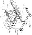
- FIG. 7is a perspective view of a mobile support system in a second position in accordance with an embodiment.
- the support arm 218 , arm 236 and carriage 234have been moved in a horizontal direction (as shown by arrow 255 ) to the second position proximate the second end 216 of the housing 204 .
- the horizontal movementmay be provided using linear bearings (not shown).
- a bias spring(not shown) may be used to push or force the carriage 234 towards the second position and hold the carriage 234 in the second position.
- the bias springmay be implemented as an over center spring. In another embodiment, the bias spring may be implemented as a spring-loaded cam follower on a linear cam.
- the carriage 234 , support arm 218 and arm 236may then be lowered, for example, by actuating a button 228 , towards the rail 244 (as shown by arrow 257 ) so that the arm 236 and base 240 are positioned on the rail 244 .
- a mechanismsuch as a scissor mechanism may be used to lower the carriage 234 .
- the carriage 234continues to be lowered downwards to disengage from the base 240 of the arm 236 .
- FIG. 8shows the carriage and support arm 218 is a lowered position in second position at the second end 216 of the housing 204 .
- the mobile support 200may then be wheeled away from the bed or table.
- FIG. 9is a perspective view looking upward towards a bottom portion of a base of an arm of a medical device in accordance with an embodiment
- FIG. 10is a side view of a mounting block in a carriage of a mobile support system in accordance with an embodiment.
- base 240includes a set of feet 238 , a lip 252 , a front side 245 and a bottom surface 250 .
- a rail detect lever 254is located on a bottom surface of lip 252 .
- the rail detect lever 254is used to make sure the arm base 240 is fully seated on the rail 244 (not shown) before the arm base 240 detaches from the mobile support 200 .
- the rail detect lever 254makes contact with the rail and either unlocks a first roller shaft 260 or a second roller shaft 262 .
- both the first roller shaft 260 and the second roller shaft 262are locked and are unlocked when the rail detect lever 254 makes contact with the rail.
- first pin 268 and a second pin 270are positioned in the first roller shaft 260 and the second roller shaft 262 , respectively.
- First pin 268 and second pin 270are shown in FIG. 10 having a cylindrical or round shape, however, other shapes may be used for the pins 268 and 270 .
- the first 268 and second 370 pins of the mounting block 241are shown in FIG. 10 .
- base 240also includes a first roller 256 and a second roller 258 that are coupled to the first roller shaft 260 and the second roller shaft 262 , respectively.
- first roller 256 and the second roller 258are in a position (not shown in FIG. 9 ) so they lie substantially parallel to the first side 245 of the base 240 and do not protrude outward from and perpendicular to the first side 245 of the base 240 .
- the mobile support 200can continue to be lowered so as to disengage the first 268 and second 270 pin of the mounting block 241 from base 240 .
- a follower pin 273 in first roller shaft 260rotates the roller shaft 260 to move the first roller 256 to a position (shown in FIG.
- Base 240also includes a friction brake 266 positioned on the first side 245 of the base 240 and a brake release 264 positioned in the bottom surface 250 of the base 240 .
- a brake release pin 272(shown in FIG. 10 ) on the mounting block 241 is positioned in the brake release 264 .
- Brake release pin 272is shown in FIG. 10 having a rectangular shape, however, other shapes may be used for the brake release pin 272 .
- FIG. 11is a front view of a mobile support system in accordance with an embodiment.
- the support arm 218 and arm 236are in the second position proximate to the second end 216 of the mobile support 200 .
- the base 240 of the arm 236is seated on the rail 244 and the brake 266 is against the rail 244 .
- the floor brake 242is released and raises up from the floor.
- the mobile support 200may then be wheeled away from the bed or table.
- the medical device mounted to the tableis shown in FIG. 1 .
- the mobile support 200may be positioned next to the side of the bed adjacent to the rail on the table.
- FIG. 12is a perspective view of a mobile support system with a lowered carriage in the second position
- FIG. 13is a perspective view of a mobile support system with a raised carriage in the second position.
- the mobile support 200is wheeled up to the table so that the first rail detect guide 230 and the second rail detect guide 232 contact the rail 244 on the bed or table. For clarity, only the rail 244 of the bed or table is shown. As discussed above with respect to FIG.
- the first 230 and second 232 rail detect guideseach include a link or switch that when actuated by contact with the rail 244 unlock the mechanisms (e.g., hydraulics) used to raise and lower the carriage 234 (and thereby the support arm 218 and lower portion 236 of the medical device arm) so that the medical device may be removed from the rail 244 .
- the mechanismse.g., hydraulics
- a usermay, for example, pump the foot pedal 224 to raise the carriage 234 , support arm 218 and arm 236 upward in a vertical direction as indicated by arrow 263 .
- actuation of the foot pedal 224causes the floor brake to lower to contact the floor (as shown by arrow 261 ) and force or urge the mobile support 200 against the rail 244 .
- the mounting block 241 on the mobile support 200engages the base 240 of the arm 236 .
- first pin 268 and a second pin 270are positioned in the first roller shaft 260 and the second roller shaft 262 , respectively.
- the follower pin 273 in first roller shaft 260first unlocks the roller shaft 260 and then rotates the roller shaft 260 to move the first roller 256 to a position (not shown in FIG. 9 ) so it lies substantially parallel to the first side 245 of the base 240 and does not protrude outward from and perpendicular to the first side 245 of the base 240 .
- the follower pin 275 in second roller shaft 262first unlocks the roller shaft 262 and then rotates the roller shaft 262 to move the second roller 258 to a position (not shown in FIG. 9 ) so it lies substantially parallel to the first side 245 of the base 240 and does not protrude outward from and perpendicular to the first side 245 of the base 240 .
- the brake release pin 272shown in FIG. 10 on the mounting block 241 is positioned in the brake release 264 .
- the brake release pin 272As the brake release pin 272 is inserted in the brake release 264 as the mobile support 200 is raised, the brake 266 is released and no longer applies a force to the rail 244 .
- the brake release pin 272makes contact with a rocker in brake release 264 and the rocker may be attached to the brake with a tie rod.
- FIG. 14is a perspective view of a mobile support system with a raised carriage at the first position in accordance with an embodiment .
- the support arm 218 , arm 236 and carriage 234have been moved in a horizontal direction (as shown by arrow 265 ) to the first position proximate the first end 214 of the housing 204 .
- the horizontal movementmay be provided using linear bearings (not shown).
- the carriage 234 , support arm 218 and arm 236may then be lowered (as shown by arrow 267 ), for example, by actuating a button 228 , into the housing so that the arm 236 and base 240 are in a storage position as shown in FIG. 15 .
- a mechanismsuch as a scissor mechanism may be used to lower the carriage 234 .
- the floor brake 242releases and moves to a raised position (as shown by arrow 269 ).
- the mobile support 200may then be wheeled away from the bed or table.
Landscapes
- Health & Medical Sciences (AREA)
- Engineering & Computer Science (AREA)
- Life Sciences & Earth Sciences (AREA)
- Public Health (AREA)
- Veterinary Medicine (AREA)
- Animal Behavior & Ethology (AREA)
- General Health & Medical Sciences (AREA)
- Biomedical Technology (AREA)
- Surgery (AREA)
- Transportation (AREA)
- Combustion & Propulsion (AREA)
- Chemical & Material Sciences (AREA)
- Mechanical Engineering (AREA)
- Nursing (AREA)
- Molecular Biology (AREA)
- Medical Informatics (AREA)
- Heart & Thoracic Surgery (AREA)
- Nuclear Medicine, Radiotherapy & Molecular Imaging (AREA)
- Pathology (AREA)
- Oral & Maxillofacial Surgery (AREA)
- Accommodation For Nursing Or Treatment Tables (AREA)
- Apparatus For Radiation Diagnosis (AREA)
Abstract
Description
Claims (25)
Priority Applications (11)
| Application Number | Priority Date | Filing Date | Title |
|---|---|---|---|
| US16/152,811US10611391B1 (en) | 2018-10-05 | 2018-10-05 | Mobile support and storage system for a medical device |
| CN202210872606.9ACN115281844B (en) | 2018-10-05 | 2019-10-03 | Mobile support and storage systems for medical equipment |
| PCT/US2019/054446WO2020072747A1 (en) | 2018-10-05 | 2019-10-03 | Mobile support and storage system for a medical device |
| EP23217096.9AEP4335405A3 (en) | 2018-10-05 | 2019-10-03 | Mobile support and storage system for a medical device |
| JP2021518607AJP7082244B2 (en) | 2018-10-05 | 2019-10-03 | Movable support and containment system for medical devices |
| EP22194515.7AEP4119086B1 (en) | 2018-10-05 | 2019-10-03 | Mobile support and storage system for a medical device |
| CN201980080582.XACN113164218B (en) | 2018-10-05 | 2019-10-03 | Mobile support and storage system for medical devices |
| EP19868438.3AEP3843654B1 (en) | 2018-10-05 | 2019-10-03 | Mobile support for a medical device |
| CN202411519207.XACN119112374A (en) | 2018-10-05 | 2019-10-03 | Mobile support and storage systems for medical equipment |
| JP2022067476AJP7275349B2 (en) | 2018-10-05 | 2022-04-15 | Mobile support and containment system for medical equipment |
| JP2022067477AJP7350931B2 (en) | 2018-10-05 | 2022-04-15 | Mobile support and containment systems for medical devices |
Applications Claiming Priority (1)
| Application Number | Priority Date | Filing Date | Title |
|---|---|---|---|
| US16/152,811US10611391B1 (en) | 2018-10-05 | 2018-10-05 | Mobile support and storage system for a medical device |
Publications (2)
| Publication Number | Publication Date |
|---|---|
| US10611391B1true US10611391B1 (en) | 2020-04-07 |
| US20200108850A1 US20200108850A1 (en) | 2020-04-09 |
Family
ID=70052913
Family Applications (1)
| Application Number | Title | Priority Date | Filing Date |
|---|---|---|---|
| US16/152,811ActiveUS10611391B1 (en) | 2018-10-05 | 2018-10-05 | Mobile support and storage system for a medical device |
Country Status (5)
| Country | Link |
|---|---|
| US (1) | US10611391B1 (en) |
| EP (3) | EP4119086B1 (en) |
| JP (3) | JP7082244B2 (en) |
| CN (3) | CN113164218B (en) |
| WO (1) | WO2020072747A1 (en) |
Cited By (11)
| Publication number | Priority date | Publication date | Assignee | Title |
|---|---|---|---|---|
| CN113893040A (en)* | 2021-09-23 | 2022-01-07 | 刘杰 | Bracket mechanism of clinical apparatus of gynaecology and obstetrics |
| US11246672B2 (en) | 2019-08-15 | 2022-02-15 | Auris Health, Inc. | Axial motion drive devices, systems, and methods for a robotic medical system |
| US20220079701A1 (en)* | 2019-01-25 | 2022-03-17 | Eurosets S.R.L. | Appliance for the transport of biomedical devices |
| CN114261438A (en)* | 2021-11-15 | 2022-04-01 | 深圳供电局有限公司 | Climbing tool and using method thereof |
| CN114391971A (en)* | 2021-12-24 | 2022-04-26 | 黄建鲜 | Portable toolbox of movable medical treatment |
| US12232838B2 (en) | 2021-08-12 | 2025-02-25 | Imperative Care, Inc. | Method of robotically performing a neurovascular procedure |
| US12329397B2 (en) | 2022-08-02 | 2025-06-17 | Imperative Care, Inc. | Fluidics management system |
| US12377206B2 (en) | 2023-05-17 | 2025-08-05 | Imperative Care, Inc. | Fluidics control system for multi catheter stack |
| US12419703B2 (en) | 2022-08-01 | 2025-09-23 | Imperative Care, Inc. | Robotic drive system for achieving supra-aortic access |
| US12433702B2 (en) | 2022-12-01 | 2025-10-07 | Imperative Care, Inc. | Telescoping drive table |
| US12440289B2 (en) | 2022-12-01 | 2025-10-14 | Imperative Care, Inc. | Method of priming an interventional device assembly |
Families Citing this family (5)
| Publication number | Priority date | Publication date | Assignee | Title |
|---|---|---|---|---|
| US10611391B1 (en)* | 2018-10-05 | 2020-04-07 | Corindus, Inc. | Mobile support and storage system for a medical device |
| DE102020200831B4 (en)* | 2020-01-23 | 2023-11-30 | Dometic Sweden Ab | BEVERAGE TROLLEY |
| CN111497922A (en)* | 2020-05-26 | 2020-08-07 | 赵艳花 | Baby carriage capable of realizing automatic braking of downward steep slope based on height difference of front wheels and rear wheels |
| CN111938959B (en)* | 2020-08-03 | 2022-07-01 | 郑州大学第一附属医院 | A medical care cart |
| US20250120867A1 (en)* | 2023-10-17 | 2025-04-17 | Care Surgical Limited | Surgical table extension for use with a surgical table |
Citations (29)
| Publication number | Priority date | Publication date | Assignee | Title |
|---|---|---|---|---|
| US3304609A (en) | 1966-02-16 | 1967-02-21 | Horowitz Norman | Dental equipment stand |
| US3922996A (en) | 1974-08-29 | 1975-12-02 | Brunswick Corp | Steering apparatus for outboard motors |
| US4199294A (en) | 1976-07-09 | 1980-04-22 | Volkswagenwerk Aktiengesellschaft | Automatic production machine |
| US4637494A (en) | 1983-11-15 | 1987-01-20 | Kabushiki Kaisha Toshiba | Apparatus for moving carriages along ladders |
| US4917619A (en) | 1987-12-26 | 1990-04-17 | Obara Corporation | Tool changer for welding robot |
| US5696574A (en) | 1995-10-27 | 1997-12-09 | Reliance Medical Products, Inc. | Ophthalmic instrument support and lighting system |
| US5907487A (en) | 1995-09-27 | 1999-05-25 | Immersion Corporation | Force feedback device with safety feature |
| US20010035702A1 (en) | 1999-12-02 | 2001-11-01 | Murphy Brian G. | Cart for surgical console |
| US20030093862A1 (en)* | 1998-12-11 | 2003-05-22 | Hill-Rom Services, Inc. | Hospital bed mechanisms |
| WO2003015428A9 (en) | 2001-08-08 | 2003-12-11 | Buchbinder Sam | Preventing unauthorized use of a wireless or wired device |
| US20050206107A1 (en)* | 2004-03-12 | 2005-09-22 | Werner Schubert | Medical device carrier with a docking station |
| US20050278851A1 (en)* | 2004-06-21 | 2005-12-22 | Demayo Edward N | Operating table support clamp |
| US6999849B2 (en) | 2002-01-24 | 2006-02-14 | John Clinton Bridges | Folding robotic system |
| US20060163829A1 (en) | 2005-01-10 | 2006-07-27 | Atlas Systems, Inc. | Modular patient support system |
| US7278615B2 (en)* | 2004-03-12 | 2007-10-09 | Trumpf Kreuzer Medizin Systeme Gmbh + Co. Kg | Coupling mechanism with a mobile infusion unit |
| US20090248042A1 (en) | 2008-03-27 | 2009-10-01 | Kirschenman Mark B | Model catheter input device |
| US20110015484A1 (en) | 2009-07-16 | 2011-01-20 | Alvarez Jeffrey B | Endoscopic robotic catheter system |
| US20110247903A1 (en) | 2010-04-07 | 2011-10-13 | Mikhail Boukhny | Systems and Methods for Console Braking |
| US20120224673A1 (en)* | 2011-03-02 | 2012-09-06 | Barker David E | Brake systems for c-arm positioning devices, apparatus containing the same and methods for using such systems |
| US8333692B2 (en) | 2005-12-26 | 2012-12-18 | Olympus Medical Systems Corp. | Endoscope and endoscopic system |
| US8348287B1 (en)* | 2009-11-30 | 2013-01-08 | Smith Phillip J | Slab cart |
| US8390438B2 (en) | 2008-09-24 | 2013-03-05 | St. Jude Medical, Atrial Fibrillation Division, Inc. | Robotic catheter system including haptic feedback |
| US20140205371A1 (en)* | 2013-01-18 | 2014-07-24 | Alexander Bally | Modular rail adapter system |
| US20140215718A1 (en)* | 2011-09-06 | 2014-08-07 | Malcolm Wootton | Operating tables and accessories |
| US8881359B2 (en) | 2010-11-11 | 2014-11-11 | Honda Motor Co., Ltd. | Machine tool assembling apparatus and method of assembling machine tool using machine tool assembling apparatus |
| US8888083B2 (en) | 2011-02-09 | 2014-11-18 | Sodick Co., Ltd. | Movement device having linear motor |
| US20150190265A1 (en)* | 2014-01-03 | 2015-07-09 | Innovative Orthopedic Technologies, Iot Ag | Devices and methods for guiding and applying traction to a patient's leg during surgery |
| US20150223892A1 (en) | 2014-02-07 | 2015-08-13 | Enovate Medical, Llc | Work platform for a wheeled medical cart |
| US20190298597A1 (en)* | 2016-09-28 | 2019-10-03 | Mizuho Corporation | Surgical head fixation apparatus |
Family Cites Families (14)
| Publication number | Priority date | Publication date | Assignee | Title |
|---|---|---|---|---|
| WO2000009061A1 (en)* | 1998-08-14 | 2000-02-24 | The General Hospital Corporation Doing Business As Massachussets General Hospital | Transfer system for portable patient care apparatus |
| US20010034721A1 (en)* | 2000-02-14 | 2001-10-25 | Jean-Pierre Boudreau | System and method for providing services to a remote user through a network |
| EP1605887A2 (en)* | 2003-03-18 | 2005-12-21 | Hill-Rom Services, Inc. | Patient care equipment management system |
| US7845601B1 (en)* | 2006-11-09 | 2010-12-07 | Modular Services Company | Medical equipment transport system |
| EP2145586B1 (en)* | 2008-07-16 | 2014-12-31 | Brainlab AG | Adapter for mounting a medical device |
| US20150223891A1 (en)* | 2014-02-07 | 2015-08-13 | Enovate Medical Llc | Medical cart access control |
| US9463127B2 (en)* | 2014-12-05 | 2016-10-11 | Leon Hochman | Transporter table system |
| WO2017041015A1 (en)* | 2015-09-04 | 2017-03-09 | Mako Surgical Corp. | Steering mechanism for portable surgical robot |
| WO2017083453A1 (en)* | 2015-11-12 | 2017-05-18 | Covidien Lp | Robotic surgical systems and methods for monitoring applied forces |
| EP3448738A1 (en)* | 2016-04-29 | 2019-03-06 | Crown Equipment Corporation | Pallet truck cart transportation device |
| US10856948B2 (en)* | 2017-05-31 | 2020-12-08 | Verb Surgical Inc. | Cart for robotic arms and method and apparatus for registering cart to surgical table |
| US10034721B1 (en) | 2017-09-27 | 2018-07-31 | Verb Surgical Inc. | Robotic arm cart having shock absorbing mechanisms and uses therefor |
| US10333296B1 (en)* | 2018-04-20 | 2019-06-25 | Verb Surgical Inc. | Surgical robotic arm with wireless power supply interface |
| US10611391B1 (en)* | 2018-10-05 | 2020-04-07 | Corindus, Inc. | Mobile support and storage system for a medical device |
- 2018
- 2018-10-05USUS16/152,811patent/US10611391B1/enactiveActive
- 2019
- 2019-10-03EPEP22194515.7Apatent/EP4119086B1/enactiveActive
- 2019-10-03CNCN201980080582.XApatent/CN113164218B/enactiveActive
- 2019-10-03CNCN202411519207.XApatent/CN119112374A/enactivePending
- 2019-10-03EPEP19868438.3Apatent/EP3843654B1/enactiveActive
- 2019-10-03WOPCT/US2019/054446patent/WO2020072747A1/ennot_activeCeased
- 2019-10-03JPJP2021518607Apatent/JP7082244B2/enactiveActive
- 2019-10-03CNCN202210872606.9Apatent/CN115281844B/enactiveActive
- 2019-10-03EPEP23217096.9Apatent/EP4335405A3/enactivePending
- 2022
- 2022-04-15JPJP2022067476Apatent/JP7275349B2/enactiveActive
- 2022-04-15JPJP2022067477Apatent/JP7350931B2/enactiveActive
Patent Citations (29)
| Publication number | Priority date | Publication date | Assignee | Title |
|---|---|---|---|---|
| US3304609A (en) | 1966-02-16 | 1967-02-21 | Horowitz Norman | Dental equipment stand |
| US3922996A (en) | 1974-08-29 | 1975-12-02 | Brunswick Corp | Steering apparatus for outboard motors |
| US4199294A (en) | 1976-07-09 | 1980-04-22 | Volkswagenwerk Aktiengesellschaft | Automatic production machine |
| US4637494A (en) | 1983-11-15 | 1987-01-20 | Kabushiki Kaisha Toshiba | Apparatus for moving carriages along ladders |
| US4917619A (en) | 1987-12-26 | 1990-04-17 | Obara Corporation | Tool changer for welding robot |
| US5907487A (en) | 1995-09-27 | 1999-05-25 | Immersion Corporation | Force feedback device with safety feature |
| US5696574A (en) | 1995-10-27 | 1997-12-09 | Reliance Medical Products, Inc. | Ophthalmic instrument support and lighting system |
| US20030093862A1 (en)* | 1998-12-11 | 2003-05-22 | Hill-Rom Services, Inc. | Hospital bed mechanisms |
| US20010035702A1 (en) | 1999-12-02 | 2001-11-01 | Murphy Brian G. | Cart for surgical console |
| WO2003015428A9 (en) | 2001-08-08 | 2003-12-11 | Buchbinder Sam | Preventing unauthorized use of a wireless or wired device |
| US6999849B2 (en) | 2002-01-24 | 2006-02-14 | John Clinton Bridges | Folding robotic system |
| US7278615B2 (en)* | 2004-03-12 | 2007-10-09 | Trumpf Kreuzer Medizin Systeme Gmbh + Co. Kg | Coupling mechanism with a mobile infusion unit |
| US20050206107A1 (en)* | 2004-03-12 | 2005-09-22 | Werner Schubert | Medical device carrier with a docking station |
| US20050278851A1 (en)* | 2004-06-21 | 2005-12-22 | Demayo Edward N | Operating table support clamp |
| US20060163829A1 (en) | 2005-01-10 | 2006-07-27 | Atlas Systems, Inc. | Modular patient support system |
| US8333692B2 (en) | 2005-12-26 | 2012-12-18 | Olympus Medical Systems Corp. | Endoscope and endoscopic system |
| US20090248042A1 (en) | 2008-03-27 | 2009-10-01 | Kirschenman Mark B | Model catheter input device |
| US8390438B2 (en) | 2008-09-24 | 2013-03-05 | St. Jude Medical, Atrial Fibrillation Division, Inc. | Robotic catheter system including haptic feedback |
| US20110015484A1 (en) | 2009-07-16 | 2011-01-20 | Alvarez Jeffrey B | Endoscopic robotic catheter system |
| US8348287B1 (en)* | 2009-11-30 | 2013-01-08 | Smith Phillip J | Slab cart |
| US20110247903A1 (en) | 2010-04-07 | 2011-10-13 | Mikhail Boukhny | Systems and Methods for Console Braking |
| US8881359B2 (en) | 2010-11-11 | 2014-11-11 | Honda Motor Co., Ltd. | Machine tool assembling apparatus and method of assembling machine tool using machine tool assembling apparatus |
| US8888083B2 (en) | 2011-02-09 | 2014-11-18 | Sodick Co., Ltd. | Movement device having linear motor |
| US20120224673A1 (en)* | 2011-03-02 | 2012-09-06 | Barker David E | Brake systems for c-arm positioning devices, apparatus containing the same and methods for using such systems |
| US20140215718A1 (en)* | 2011-09-06 | 2014-08-07 | Malcolm Wootton | Operating tables and accessories |
| US20140205371A1 (en)* | 2013-01-18 | 2014-07-24 | Alexander Bally | Modular rail adapter system |
| US20150190265A1 (en)* | 2014-01-03 | 2015-07-09 | Innovative Orthopedic Technologies, Iot Ag | Devices and methods for guiding and applying traction to a patient's leg during surgery |
| US20150223892A1 (en) | 2014-02-07 | 2015-08-13 | Enovate Medical, Llc | Work platform for a wheeled medical cart |
| US20190298597A1 (en)* | 2016-09-28 | 2019-10-03 | Mizuho Corporation | Surgical head fixation apparatus |
Non-Patent Citations (1)
| Title |
|---|
| International Search Report and Written Opinion for PCT/US2019/054446; dated Feb. 7, 2020; 11 pages. |
Cited By (14)
| Publication number | Priority date | Publication date | Assignee | Title |
|---|---|---|---|---|
| US20220079701A1 (en)* | 2019-01-25 | 2022-03-17 | Eurosets S.R.L. | Appliance for the transport of biomedical devices |
| US11246672B2 (en) | 2019-08-15 | 2022-02-15 | Auris Health, Inc. | Axial motion drive devices, systems, and methods for a robotic medical system |
| US11272995B2 (en) | 2019-08-15 | 2022-03-15 | Auris Health, Inc. | Axial motion drive devices, systems, and methods for a robotic medical system |
| US12376928B2 (en) | 2021-08-12 | 2025-08-05 | Imperative Care, Inc. | Catheter drive system for supra-aortic access |
| US12232838B2 (en) | 2021-08-12 | 2025-02-25 | Imperative Care, Inc. | Method of robotically performing a neurovascular procedure |
| CN113893040B (en)* | 2021-09-23 | 2023-04-14 | 刘杰 | Bracket mechanism of clinical apparatus of gynaecology and obstetrics |
| CN113893040A (en)* | 2021-09-23 | 2022-01-07 | 刘杰 | Bracket mechanism of clinical apparatus of gynaecology and obstetrics |
| CN114261438A (en)* | 2021-11-15 | 2022-04-01 | 深圳供电局有限公司 | Climbing tool and using method thereof |
| CN114391971A (en)* | 2021-12-24 | 2022-04-26 | 黄建鲜 | Portable toolbox of movable medical treatment |
| US12419703B2 (en) | 2022-08-01 | 2025-09-23 | Imperative Care, Inc. | Robotic drive system for achieving supra-aortic access |
| US12329397B2 (en) | 2022-08-02 | 2025-06-17 | Imperative Care, Inc. | Fluidics management system |
| US12433702B2 (en) | 2022-12-01 | 2025-10-07 | Imperative Care, Inc. | Telescoping drive table |
| US12440289B2 (en) | 2022-12-01 | 2025-10-14 | Imperative Care, Inc. | Method of priming an interventional device assembly |
| US12377206B2 (en) | 2023-05-17 | 2025-08-05 | Imperative Care, Inc. | Fluidics control system for multi catheter stack |
Also Published As
| Publication number | Publication date |
|---|---|
| EP4335405A2 (en) | 2024-03-13 |
| JP2022504263A (en) | 2022-01-13 |
| JP7082244B2 (en) | 2022-06-07 |
| JP2022093408A (en) | 2022-06-23 |
| EP3843654B1 (en) | 2022-11-23 |
| JP7275349B2 (en) | 2023-05-17 |
| EP4335405A3 (en) | 2024-06-05 |
| EP3843654A4 (en) | 2021-10-20 |
| EP4119086A1 (en) | 2023-01-18 |
| EP3843654A1 (en) | 2021-07-07 |
| US20200108850A1 (en) | 2020-04-09 |
| WO2020072747A1 (en) | 2020-04-09 |
| EP4119086B1 (en) | 2024-03-06 |
| CN119112374A (en) | 2024-12-13 |
| JP2022093407A (en) | 2022-06-23 |
| CN113164218B (en) | 2022-10-28 |
| EP4119086C0 (en) | 2024-03-06 |
| CN115281844A (en) | 2022-11-04 |
| CN115281844B (en) | 2025-01-21 |
| CN113164218A (en) | 2021-07-23 |
| JP7350931B2 (en) | 2023-09-26 |
Similar Documents
| Publication | Publication Date | Title |
|---|---|---|
| US10611391B1 (en) | Mobile support and storage system for a medical device | |
| US8469651B2 (en) | Conveyance device using carriage | |
| JP5294272B2 (en) | Guide wheel assemblies, especially guide wheel assemblies for hospital beds | |
| JP2007222607A (en) | Patient support apparatus having automatic contour adjusting function | |
| KR20090049528A (en) | A fence of transporting stretcher etc. in the hospital and it's lock apparatus | |
| KR101043195B1 (en) | Iron fence and lock mechanism such as stretcher for hospital transport | |
| EP0911455B1 (en) | Furniture | |
| JP4001506B2 (en) | Bed table equipment | |
| JP3286284B2 (en) | Footrest fixing device | |
| CN221357153U (en) | Medical instrument transfer device | |
| JP2552705Y2 (en) | bed | |
| JP7603956B2 (en) | Bedside table | |
| JP2017018260A (en) | Bed equipment | |
| JPH04818Y2 (en) | ||
| JPH08133243A (en) | Apparatus for automatically opening/closing container lid | |
| JPH0347616Y2 (en) | ||
| US11039969B2 (en) | Overhead lift units, systems, and methods for mounting and transporting an overhead lift unit | |
| JPH0647075A (en) | Intermediating cart | |
| JPH0415068Y2 (en) | ||
| CN117731406A (en) | Medical instrument transfer device |
Legal Events
| Date | Code | Title | Description |
|---|---|---|---|
| FEPP | Fee payment procedure | Free format text:ENTITY STATUS SET TO UNDISCOUNTED (ORIGINAL EVENT CODE: BIG.); ENTITY STATUS OF PATENT OWNER: LARGE ENTITY | |
| AS | Assignment | Owner name:CORINDUS, INC., MASSACHUSETTS Free format text:ASSIGNMENT OF ASSIGNORS INTEREST;ASSIGNOR:COOPER PERKINS, INC.;REEL/FRAME:050587/0522 Effective date:20190718 Owner name:COOPER PERKINS, INC., MASSACHUSETTS Free format text:ASSIGNMENT OF ASSIGNORS INTEREST;ASSIGNORS:ROW, GORDON;LAING, GENEVIEVE R.K.;EVANS, CHRISTOPHER O.;AND OTHERS;REEL/FRAME:050587/0442 Effective date:20190716 Owner name:CORINDUS, INC., MASSACHUSETTS Free format text:ASSIGNMENT OF ASSIGNORS INTEREST;ASSIGNOR:KLEM, ERIC;REEL/FRAME:050587/0684 Effective date:20190924 | |
| STCF | Information on status: patent grant | Free format text:PATENTED CASE | |
| MAFP | Maintenance fee payment | Free format text:PAYMENT OF MAINTENANCE FEE, 4TH YEAR, LARGE ENTITY (ORIGINAL EVENT CODE: M1551); ENTITY STATUS OF PATENT OWNER: LARGE ENTITY Year of fee payment:4 | |
| AS | Assignment | Owner name:SIEMENS HEALTHINEERS ENDOVASCULAR ROBOTICS, INC., MASSACHUSETTS Free format text:CHANGE OF NAME;ASSIGNOR:CORINDUS, INC.;REEL/FRAME:069333/0219 Effective date:20241018 |