US10610385B2 - Multi-modal upper limb prosthetic device control using myoelectric signals - Google Patents
Multi-modal upper limb prosthetic device control using myoelectric signalsDownload PDFInfo
- Publication number
- US10610385B2 US10610385B2US14/765,638US201414765638AUS10610385B2US 10610385 B2US10610385 B2US 10610385B2US 201414765638 AUS201414765638 AUS 201414765638AUS 10610385 B2US10610385 B2US 10610385B2
- Authority
- US
- United States
- Prior art keywords
- prosthesis
- wearer
- operating
- operating parameter
- signal
- Prior art date
- Legal status (The legal status is an assumption and is not a legal conclusion. Google has not performed a legal analysis and makes no representation as to the accuracy of the status listed.)
- Active
Links
- 230000003183myoelectrical effectEffects0.000titleclaims15
- 210000001364upper extremityAnatomy0.000title1
- 238000000034methodMethods0.000claimsabstractdescription54
- 230000004044responseEffects0.000claimsabstractdescription36
- 210000003205muscleAnatomy0.000claimsdescription58
- 230000000638stimulationEffects0.000claimsdescription7
- 230000001133accelerationEffects0.000claimsdescription6
- 238000005259measurementMethods0.000claimsdescription6
- 238000007781pre-processingMethods0.000claimsdescription3
- 238000012545processingMethods0.000claimsdescription3
- 230000007704transitionEffects0.000claims2
- 230000000694effectsEffects0.000description38
- 210000003813thumbAnatomy0.000description17
- 230000008569processEffects0.000description16
- 230000009471actionEffects0.000description13
- 210000003811fingerAnatomy0.000description11
- 210000000707wristAnatomy0.000description10
- 230000006870functionEffects0.000description9
- 210000000245forearmAnatomy0.000description8
- 210000005224forefingerAnatomy0.000description6
- 230000003993interactionEffects0.000description6
- 230000003387muscularEffects0.000description5
- 230000001537neural effectEffects0.000description5
- 230000008859changeEffects0.000description4
- 238000007918intramuscular administrationMethods0.000description4
- 230000009467reductionEffects0.000description4
- 210000004556brainAnatomy0.000description3
- 210000002683footAnatomy0.000description3
- 239000007943implantSubstances0.000description3
- 210000000236metacarpal boneAnatomy0.000description3
- 230000004048modificationEffects0.000description3
- 238000012986modificationMethods0.000description3
- 210000000578peripheral nerveAnatomy0.000description3
- 210000000278spinal cordAnatomy0.000description3
- 238000004497NIR spectroscopyMethods0.000description2
- 230000003044adaptive effectEffects0.000description2
- 238000000605extractionMethods0.000description2
- 238000000513principal component analysisMethods0.000description2
- 230000002787reinforcementEffects0.000description2
- 230000003595spectral effectEffects0.000description2
- 230000003068static effectEffects0.000description2
- 230000001960triggered effectEffects0.000description2
- 206010049565Muscle fatigueDiseases0.000description1
- 238000002266amputationMethods0.000description1
- 238000013459approachMethods0.000description1
- 238000013528artificial neural networkMethods0.000description1
- 230000008901benefitEffects0.000description1
- 238000001514detection methodMethods0.000description1
- 238000010586diagramMethods0.000description1
- 210000003414extremityAnatomy0.000description1
- 238000001914filtrationMethods0.000description1
- 210000004247handAnatomy0.000description1
- 230000006872improvementEffects0.000description1
- 210000004932little fingerAnatomy0.000description1
- 238000012544monitoring processMethods0.000description1
- 238000003909pattern recognitionMethods0.000description1
- 230000009131signaling functionEffects0.000description1
- 238000001228spectrumMethods0.000description1
- 210000003371toeAnatomy0.000description1
- 238000012549trainingMethods0.000description1
Images


Classifications
- A—HUMAN NECESSITIES
- A61—MEDICAL OR VETERINARY SCIENCE; HYGIENE
- A61F—FILTERS IMPLANTABLE INTO BLOOD VESSELS; PROSTHESES; DEVICES PROVIDING PATENCY TO, OR PREVENTING COLLAPSING OF, TUBULAR STRUCTURES OF THE BODY, e.g. STENTS; ORTHOPAEDIC, NURSING OR CONTRACEPTIVE DEVICES; FOMENTATION; TREATMENT OR PROTECTION OF EYES OR EARS; BANDAGES, DRESSINGS OR ABSORBENT PADS; FIRST-AID KITS
- A61F2/00—Filters implantable into blood vessels; Prostheses, i.e. artificial substitutes or replacements for parts of the body; Appliances for connecting them with the body; Devices providing patency to, or preventing collapsing of, tubular structures of the body, e.g. stents
- A61F2/50—Prostheses not implantable in the body
- A61F2/68—Operating or control means
- A61F2/70—Operating or control means electrical
- A61F2/72—Bioelectric control, e.g. myoelectric
- A—HUMAN NECESSITIES
- A61—MEDICAL OR VETERINARY SCIENCE; HYGIENE
- A61F—FILTERS IMPLANTABLE INTO BLOOD VESSELS; PROSTHESES; DEVICES PROVIDING PATENCY TO, OR PREVENTING COLLAPSING OF, TUBULAR STRUCTURES OF THE BODY, e.g. STENTS; ORTHOPAEDIC, NURSING OR CONTRACEPTIVE DEVICES; FOMENTATION; TREATMENT OR PROTECTION OF EYES OR EARS; BANDAGES, DRESSINGS OR ABSORBENT PADS; FIRST-AID KITS
- A61F2/00—Filters implantable into blood vessels; Prostheses, i.e. artificial substitutes or replacements for parts of the body; Appliances for connecting them with the body; Devices providing patency to, or preventing collapsing of, tubular structures of the body, e.g. stents
- A61F2/50—Prostheses not implantable in the body
- A61F2/54—Artificial arms or hands or parts thereof
- A61F2/58—Elbows; Wrists ; Other joints; Hands
- A61F2/583—Hands; Wrist joints
- A61F2/586—Fingers
- A—HUMAN NECESSITIES
- A61—MEDICAL OR VETERINARY SCIENCE; HYGIENE
- A61F—FILTERS IMPLANTABLE INTO BLOOD VESSELS; PROSTHESES; DEVICES PROVIDING PATENCY TO, OR PREVENTING COLLAPSING OF, TUBULAR STRUCTURES OF THE BODY, e.g. STENTS; ORTHOPAEDIC, NURSING OR CONTRACEPTIVE DEVICES; FOMENTATION; TREATMENT OR PROTECTION OF EYES OR EARS; BANDAGES, DRESSINGS OR ABSORBENT PADS; FIRST-AID KITS
- A61F2/00—Filters implantable into blood vessels; Prostheses, i.e. artificial substitutes or replacements for parts of the body; Appliances for connecting them with the body; Devices providing patency to, or preventing collapsing of, tubular structures of the body, e.g. stents
- A61F2/50—Prostheses not implantable in the body
- A61F2/68—Operating or control means
- A61F2/70—Operating or control means electrical
- A—HUMAN NECESSITIES
- A61—MEDICAL OR VETERINARY SCIENCE; HYGIENE
- A61F—FILTERS IMPLANTABLE INTO BLOOD VESSELS; PROSTHESES; DEVICES PROVIDING PATENCY TO, OR PREVENTING COLLAPSING OF, TUBULAR STRUCTURES OF THE BODY, e.g. STENTS; ORTHOPAEDIC, NURSING OR CONTRACEPTIVE DEVICES; FOMENTATION; TREATMENT OR PROTECTION OF EYES OR EARS; BANDAGES, DRESSINGS OR ABSORBENT PADS; FIRST-AID KITS
- A61F2/00—Filters implantable into blood vessels; Prostheses, i.e. artificial substitutes or replacements for parts of the body; Appliances for connecting them with the body; Devices providing patency to, or preventing collapsing of, tubular structures of the body, e.g. stents
- A61F2/50—Prostheses not implantable in the body
- A61F2/54—Artificial arms or hands or parts thereof
- A61F2/58—Elbows; Wrists ; Other joints; Hands
- A61F2/583—Hands; Wrist joints
- A61F2/586—Fingers
- A61F2002/587—Thumbs
- A—HUMAN NECESSITIES
- A61—MEDICAL OR VETERINARY SCIENCE; HYGIENE
- A61F—FILTERS IMPLANTABLE INTO BLOOD VESSELS; PROSTHESES; DEVICES PROVIDING PATENCY TO, OR PREVENTING COLLAPSING OF, TUBULAR STRUCTURES OF THE BODY, e.g. STENTS; ORTHOPAEDIC, NURSING OR CONTRACEPTIVE DEVICES; FOMENTATION; TREATMENT OR PROTECTION OF EYES OR EARS; BANDAGES, DRESSINGS OR ABSORBENT PADS; FIRST-AID KITS
- A61F2/00—Filters implantable into blood vessels; Prostheses, i.e. artificial substitutes or replacements for parts of the body; Appliances for connecting them with the body; Devices providing patency to, or preventing collapsing of, tubular structures of the body, e.g. stents
- A61F2/50—Prostheses not implantable in the body
- A61F2/68—Operating or control means
- A61F2002/6827—Feedback system for providing user sensation, e.g. by force, contact or position
- A—HUMAN NECESSITIES
- A61—MEDICAL OR VETERINARY SCIENCE; HYGIENE
- A61F—FILTERS IMPLANTABLE INTO BLOOD VESSELS; PROSTHESES; DEVICES PROVIDING PATENCY TO, OR PREVENTING COLLAPSING OF, TUBULAR STRUCTURES OF THE BODY, e.g. STENTS; ORTHOPAEDIC, NURSING OR CONTRACEPTIVE DEVICES; FOMENTATION; TREATMENT OR PROTECTION OF EYES OR EARS; BANDAGES, DRESSINGS OR ABSORBENT PADS; FIRST-AID KITS
- A61F2/00—Filters implantable into blood vessels; Prostheses, i.e. artificial substitutes or replacements for parts of the body; Appliances for connecting them with the body; Devices providing patency to, or preventing collapsing of, tubular structures of the body, e.g. stents
- A61F2/50—Prostheses not implantable in the body
- A61F2/68—Operating or control means
- A61F2/70—Operating or control means electrical
- A61F2002/701—Operating or control means electrical operated by electrically controlled means, e.g. solenoids or torque motors
- A—HUMAN NECESSITIES
- A61—MEDICAL OR VETERINARY SCIENCE; HYGIENE
- A61F—FILTERS IMPLANTABLE INTO BLOOD VESSELS; PROSTHESES; DEVICES PROVIDING PATENCY TO, OR PREVENTING COLLAPSING OF, TUBULAR STRUCTURES OF THE BODY, e.g. STENTS; ORTHOPAEDIC, NURSING OR CONTRACEPTIVE DEVICES; FOMENTATION; TREATMENT OR PROTECTION OF EYES OR EARS; BANDAGES, DRESSINGS OR ABSORBENT PADS; FIRST-AID KITS
- A61F2/00—Filters implantable into blood vessels; Prostheses, i.e. artificial substitutes or replacements for parts of the body; Appliances for connecting them with the body; Devices providing patency to, or preventing collapsing of, tubular structures of the body, e.g. stents
- A61F2/50—Prostheses not implantable in the body
- A61F2/68—Operating or control means
- A61F2/70—Operating or control means electrical
- A61F2002/704—Operating or control means electrical computer-controlled, e.g. robotic control
Definitions
- the present inventionrelates to a prosthesis, particularly, but not exclusively, a hand prosthesis.
- Prosthetic hands with powered digitsare known.
- WO 2007/063266 and WO 1995/24875disclose a prosthesis with a mechanically operated digit member that is moved by an electric motor.
- the prosthesisis capable of operating in a number of modes, such as function modes (grasp, pinch, etc.) and gesture modes (point etc.).
- the methodmay further further comprise the steps of:
- the methodmay further comprise a final step of sending a feedback signal to the wearer of the prosthesis, the feedback signal indicative of the selected operating mode and operating parameter.
- the operating profilemay be divided into a plurality of regions, each region representing a separate operating mode and operating parameter, and wherein the comparison step comprises plotting in one of the plurality of regions a resultant input command signal based upon the one or more input control signals, and determining the operating mode and operating parameter associated with that region.
- the at least one input control signalmay be generated by one or more sensors attached to the wearer of the prosthesis.
- a prosthesiscomprising:
- the electronic control devicemay include a memory for storing input control signals received so as to establish an input control signal pattern, and a program which predicts a desired operating mode and operating parameter based upon the input control signal pattern upon receiving the at least one control signal from the wearer of the prosthesis.
- the electronic control devicemay include a signal generator which sends a feedback signal to the wearer of the prosthesis, the feedback signal indicative of the selected operating mode and operating parameter.
- the prosthesismay further comprise one or more sensors attached to the wearer of the prosthesis for the generation of the at least one input control signal.
- a prosthesiscomprising:
- the moveable componentmay be a digit of a hand prosthesis.
- the digitmay be a finger or a thumb of a hand prosthesis.
- the digitsmay be moveable relative to a body part to which they are attached.
- the digitsmay be rotatably and/or pivotably moveable relative to a body part to which they are attached.
- the body partmay be attachable to the wearer of the prosthesis.
- the prosthesismay be configured such that it is attachable to a partial-hand amputee. That is, the prosthesis may be arranged such that it is attachable to a wearer who is missing one or more fingers or a thumb from their hand, with the moveable components replacing the missing fingers or thumb.
- the moveable componentmay be a body part to which a digit may be attached.
- the moveable componentmay be a hand chassis.
- the moveable componentmay be a wrist or cuff component.
- the body part or hand chassismay be rotatably attachable to the wearer of the prosthesis.
- operating modeis considered here to mean an operating movement of the moveable component in response to an input command signal from the wearer of the prosthesis.
- the term operating modeis considered to mean the operational interaction between the moveable components in response to an input command signal from the wearer of the prosthesis.
- Each operating modeprovides for a discrete operating movement of the moveable component.
- each operating modeprovides for a discrete operational interaction between the moveable components.
- the operational interaction between the moveable componentsmay include functional tasks that the wearer of the prosthesis wishes the components to perform, such as pressing the components together in a pinching action, or moving the components to a desired position to create a gesture, such as pointing.
- the term operating parameteris considered here to mean an operating condition of the moveable component in response to an input command signal from the wearer of the prosthesis.
- the operating parameter of the moveable componentmay include its speed, acceleration, deceleration, force, operating duration, amount of extension, amount of flexion, angle of rotation etc.
- the operating parameter of the moveable componentmay be proportional to the input command signal. That is, the operating condition of the moveable component may be proportional to the input command signal.
- the electronic devicemay be operable to select both the operating mode of the at least one moveable component and the operating parameters of the moveable components in response to an input command signal from the wearer of the prosthesis.
- the electronic devicemay be operable to simultaneously select both the operating mode of the at least one moveable component and at least one operating parameter of the at least one moveable component in response to an input command signal from the wearer of the prosthesis.
- the electronic devicemay be operable to select both the operating mode of the at least one moveable component and the at least one operating parameter of at least one moveable component in response to a single input command signal from the wearer of the prosthesis.
- the at least one moveable componentmay have a plurality of operating modes.
- the prosthesismay comprise a plurality of moveable components.
- Each moveable componentmay have two or more operating modes and at least one operating parameter.
- Each moveable componentmay have a plurality of operating parameters.
- the electronic devicemay be operable to select one of the plurality of operating modes of the at least one moveable component and at least one operating parameter of the at least one moveable component in response to an input command signal from the wearer of the prosthesis.
- the electronic devicemay be operable to select one of the plurality of operating modes of the at least one moveable component and at least one operating parameter of the at least one moveable component in response to a predetermined input command signal from the wearer of the prosthesis.
- Each predetermined input command signalmay result in selection of a corresponding predetermined operating mode of the at least one moveable component and at least one operating parameter of the at least one moveable component.
- the input command signalmay comprise two or more input signals from the wearer of the prosthesis.
- the input command signalmay comprise a plurality of input signals from the wearer of the prosthesis.
- the input signals from the wearer of the prosthesismay be provided via one or more switches.
- the switchesmay be analogue or digital switches.
- the switchesmay be actuated by residual movement of the wearer of the prosthesis, wrist and/or shoulder movement of the wearer of the prosthesis, movement of the remnant digits and/or knuckles, or the like.
- the input signals from the wearer of the prosthesismay be provided by electrophysiological signals derived from the activity of, or from, surface electromyographic (EMG) and intramuscular activity of residual muscle actions of the wearer of the prosthesis, electroneurographic (ENG) activity of residual peripheral nerves of the wearer of the prosthesis, signals derived from one or more neural implants in the wearer of the prosthesis implanted in the brain or spinal cord, EMG activity from reinnervated muscles, muscles of the feet and/or chest, or the like.
- EMGsurface electromyographic
- ENGelectroneurographic
- the input signals from the wearer of the prosthesismay be provided by non-electrophysiological signals derived from the activity of pressure sensitive resistors on the wearer of the prosthesis, near infrared spectroscopy signal, or bend sensitive resistors on the wearer of the body to capture any residual movement of the digits, wrist, elbow or shoulder of the wearer of the prosthesis, or the like.
- the input signals from the wearer of the prosthesismay be provided directly by signals derived from neural, spinal or muscular activity, for example, electromyographic (EMG) activity of hand muscle/forearm muscle actions, or residual muscle actions, of the wearer of the prosthesis recorded non-invasively from the surface of the skin or invasively from superficial or deep muscular structures with using needle or an array of needle electrodes.
- EMGelectromyographic
- the prosthesismay be controlled by the activity of any combination of intrinsic and extrinsic hand muscle group, such as muscles in the thenar and hypothenar muscles, the interossei muscles originating between the metacarpal bones, the long flexors and extensors in the forearm, e.g. extensor pollicis longus muscle, extensor/flexor indicis muscle, or the like.
- the input signalsmay be the results, or signature, of the recorded signal of a mathematical operation on the electrophysiological or non-electrophysiological measurements from the wearer of the prosthesis.
- the signature of the EMGmay be the amplitude or the energy of the signal.
- the mathematical signatures of the EMG signal in the time domainmay be: amplitude (Mean absolute value of EMG and all its variations), energy (Square integral, Variance, Root means square (RMS)), number of zero crossing, Wilson amplitude, waveform length, slope sign change, or histogram of EMG.
- the mathematical signatures of the EMG signal in the frequency domainmay be: autoregressive and spectral coefficients or median and mean frequency.
- the mathematical signatures of the EMG signal in the time-frequencymay be: coefficients of the short time Fourier transform, or discrete or continuous wavelet coefficients.
- the mathematical signatures of the EMG signal in higher order statisticsmay be: skewness or kurtosis of EMG or any other higher even-or-odd-order statistics, entropy or negentropy.
- the above signaturesmay be extracted and a dimensionality reduction technique may be used, such as principal component analysis, to reduce to input dimensions to 2, 3, . . . etc.
- the electronic devicemay include a predetermined operating profile of the prosthesis.
- the electronic devicemay include one or more predetermined operating profiles.
- the or each, predetermined operating profile of the prosthesismay include an operating profile of the input command signal, operating mode of the moveable component and operating parameter(s) of the moveable component of the prosthesis.
- the or each, predetermined operating profile of the prosthesismay be based on one or more input signals from the wearer of the prosthesis to produce an input command signal which results in selection of both the operating mode of the at least one moveable component and at least one operating parameter of the at least one moveable component.
- the electronic devicemay be operable to modify the, or each, predetermined operating profile of the prosthesis to a modified operating profile.
- the electronic devicemay be operable to modify the, or each, predetermined operating profile to a new operating profile that the wearer of the prosthesis finds easier to operate.
- the modification of the, or each, predetermined operating profilemay be reinforcement learning, iterative learning, co-adaptive control or the like.
- the electronic devicemay be operable to switch between two or more predetermined operating profiles.
- the or each, predetermined operating profile of the prosthesismay be based on one or more input signals from the wearer of the prosthesis to produce an input command signal which results in simultaneous selection of both the operating mode of the at least one moveable component and at least one operating parameter of the at least one moveable component.
- the electronic devicemay be further operable to produce an output signal indicative of the operating mode of the at least one moveable component and/or the operating parameter of the at least one moveable component.
- the electronic devicemay be further operable to produce an output signal indicative of the operating mode of the at least one moveable component and the operating parameters of the moveable component.
- the electronic devicemay be further operable to communicate the output signal to the wearer of the prosthesis.
- the output signalmay be communicated to the wearer of the prosthesis visually, kinaesthetically, aurally or neurally.
- the output signalmay be communicated non-invasively to the wearer of the prosthesis via electro-tactile or vibro-tactile stimulation of the body skin.
- the electro-tactile or vibro-tactile stimulation to the body skinmay be provided at the forearm, shoulder, neck, or the like.
- the electronic devicemay be further operable to process the input command signal from the wearer of the prosthesis.
- the electronic devicemay be further operable to process the input signals from the wearer of the prosthesis.
- the electronic devicemay be further operable to pre-process the input signals from the wearer of the prosthesis.
- the electronic devicemay be further operable to pre-process the input signals from the wearer of the prosthesis to predict the intended input command signal.
- the electronic devicemay be further operable to select both an operating mode of the at least one moveable component and at least one operating parameter of the at least one moveable component in response to the predicted input command signal.
- the electronic devicemay include a processor.
- the processormay be operable to control the operation of the prosthesis.
- the processormay be operable to control the operation of the moveable component of the prosthesis.
- the processormay be operable to select both the operating mode of the at least one moveable component and at least one operating parameter of the at least one moveable component in response to the input command signal from the wearer of the prosthesis.
- the electronic devicemay include firmware.
- the firmwaremay be operable to control the operation of the prosthesis.
- the firmwaremay be operable to control the operation of the moveable component of the prosthesis.
- the firmwaremay be operable to select both the operating mode of the at least one moveable component and at least one operating parameter of the at least one moveable component in response to the input command signal from the wearer of the prosthesis.
- the processormay include the, or each, predetermined operating profile of the prosthesis.
- the electronic devicemay be located with the prosthesis.
- the electronic devicemay be located with the wearer of the prosthesis.
- a method of operating a prosthesis having at least one moveable component, the at least one moveable component having two or more operating modes and at least one operating parameter, and an electronic device operable to control the operation of the at least one moveable component of the prosthesiscomprising the steps of:
- the moveable componentmay be a digit of a hand prosthesis.
- the digitmay be a finger or a thumb of a hand prosthesis.
- the digitsmay be moveable relative to a body part to which they are attached.
- the digitsmay be rotatably and/or pivotably moveable relative to a body part to which they are attached.
- the body partmay be attachable to the wearer of the prosthesis.
- the prosthesismay be configured such that it is attachable to a partial-hand amputee. That is, the prosthesis may be arranged such that it is attachable to a wearer who is missing one or more fingers or a thumb from their hand, with the moveable components replacing the missing fingers or thumb.
- the moveable componentmay be a body part to which a digit may be attached.
- the moveable componentmay be a hand chassis.
- the moveable componentmay be a wrist or cuff component.
- the body part or hand chassismay be rotatably attachable to the wearer of the prosthesis.
- operating modeis considered here to mean an operating movement of the moveable component in response to an input command signal from the wearer of the prosthesis.
- the term operating modeis considered to mean the operational interaction between the moveable components in response to an input command signal from the wearer of the prosthesis.
- Each operating modeprovides for a discrete operating movement of the moveable component.
- each operating modeprovides for a discrete operational interaction between the moveable components.
- the operational interaction between the moveable componentsmay include functional tasks that the wearer of the prosthesis wishes the components to perform, such as pressing the components together in a pinching action, or moving the components to a desired position to create a gesture, such as pointing.
- the term operating parameteris considered here to mean an operating condition of the moveable component in response to an input command signal from the wearer of the prosthesis.
- the operating parameter of the moveable componentmay include its speed, acceleration, deceleration, force, operating duration, amount of extension, amount of flexion, angle of rotation etc.
- the operating parameter of the moveable componentmay be proportional to the input command signal. That is, the operating condition of the moveable component may be proportional to the input command signal.
- the electronic devicemay be operable to select both the operating mode of the at least one moveable component and the operating parameters of the moveable components in response to an input command signal from the wearer of the prosthesis.
- the electronic devicemay be operable to simultaneously select both the operating mode of the at least one moveable component and at least one operating parameter of the at least one moveable component in response to an input command signal from the wearer of the prosthesis.
- the electronic devicemay be provided with a single input command signal from the wearer of the prosthesis.
- the electronic devicemay be operable to select both the operating mode of the at least one moveable component and at least one operating parameter of the at least one moveable component in response to a single input command signal from the wearer of the prosthesis.
- the at least one moveable componentmay have a plurality of operating modes.
- the prosthesismay comprise a plurality of moveable components.
- Each moveable componentmay have two or more operating modes and at least one operating parameter.
- Each moveable componentmay have a plurality of operating parameters.
- the electronic devicemay be operable to select one of the plurality of operating modes of the at least one moveable component and at least one operating parameter of the at least one moveable component in response to an input command signal from the wearer of the prosthesis.
- the electronic devicemay be operable to select one of the plurality of operating modes of the at least one moveable component and at least one operating parameter of the at least one moveable component in response to a predetermined input command signal from the wearer of the prosthesis.
- Each predetermined input command signalmay result in selection of a corresponding predetermined operating mode of the at least one moveable component and at least one operating parameter of the at least one moveable component.
- the input command signalmay comprise two or more input signals from the wearer of the prosthesis.
- the input command signalmay comprise a plurality of input signals from the wearer of the prosthesis.
- the input signals from the wearer of the prosthesismay be provided via one or more switches.
- the switchesmay be analogue or digital switches.
- the switchesmay be actuated by residual movement of the wearer of the prosthesis, wrist and/or shoulder movement of the wearer of the prosthesis, movement of the remnant digits and/or knuckles, or the like.
- the input signals from the wearer of the prosthesismay be provided by electrophysiological signals derived from the activity of, or from, surface electromyographic (EMG) and intramuscular activity of residual muscle actions of the wearer of the prosthesis, electroneurographic (ENG) activity of residual peripheral nerves of the wearer of the prosthesis, signals derived from one or more neural implants in the wearer of the prosthesis implanted in the brain or spinal cord, EMG activity from re-innervated muscles, muscles of the feet and/or chest, or the like.
- EMGsurface electromyographic
- ENGelectroneurographic
- the input signals from the wearer of the prosthesismay be provided by non-electrophysiological signals derived from the activity of pressure sensitive resistors on the wearer of the prosthesis, near infrared spectroscopy signal, or bend sensitive resistors on the wearer of the body to capture any residual movement of the digits, wrist, elbow or shoulder of the wearer of the prosthesis, or the like.
- the input signals from the wearer of the prosthesismay be provided directly by signals derived from neural, spinal or muscular activity, for example, electromyographic (EMG) activity of hand muscle/forearm muscle actions, or residual muscle actions, of the wearer of the prosthesis recorded non-invasively from the surface of the skin or invasively from superficial or deep muscular structures with using needle or an array of needle electrodes.
- EMGelectromyographic
- the prosthesismay be controlled by the activity of any combination of intrinsic and extrinsic hand muscle group, such as muscles in the thenar and hypothenar muscles, the interossei muscles originating between the metacarpal bones, the long flexors and extensors in the forearm, e.g. extensor pollicis longus muscle, extensor/flexor indicis muscle, or the like.
- the input signalsmay be the results, or signature of the recorded signal of a mathematical operation on the electrophysiological or non-electrophysiological measurements from the wearer of the prosthesis.
- the signature of the EMGmay be the amplitude or the energy of the signal.
- the mathematical signatures of the EMG signal in the time domainmay be: amplitude (Mean absolute value of EMG and all its variations), energy (Square integral, Variance, Root means square (RMS)), number of zero crossing, Wilson amplitude, waveform length, slope sign change, or histogram of EMG.
- the mathematical signatures of the EMG signal in the frequency domainmay be: autoregressive and spectral coefficients or median and mean frequency.
- the mathematical signatures of the EMG signal in the time-frequencymay be: coefficients of the short time Fourier transform, or discrete or continuous wavelet coefficients.
- the mathematical signatures of the EMG signal in higher order statisticsmay be: skewness or kurtosis of EMG or any other higher even-or-odd-order statistics, entropy or negentropy.
- the above signaturesmay be extracted and a dimensionality reduction technique may be used, such as principal component analysis, to reduce to input dimensions to 2, 3, . . . etc.
- the methodmay comprise the further step of providing the electronic device with a predetermined operating profile of the prosthesis.
- the methodmay comprise the further step of providing the electronic device with one or more predetermined operating profiles of the prosthesis.
- the or each, predetermined operating profile of the prosthesismay include an operating profile of the input command signal, operating mode of the moveable component and operating parameter(s) of the moveable component of the prosthesis.
- the or each, predetermined operating profile of the prosthesismay be based on one or more input signals from the wearer of the prosthesis to produce an input command signal which results in selection of both the operating mode of the at least one moveable component and at least one operating parameter of the at least one of the moveable component.
- the electronic devicemay be operable to modify the, or each, predetermined operating profile of the prosthesis to a modified operating profile.
- the electronic devicemay be operable to modify the, or each, predetermined operating profile to a new operating profile that the wearer of the prosthesis finds easier to operate.
- the modification of the, or each, predetermined operating profilemay be reinforcement learning, iterative learning, co-adaptive control or the like.
- the electronic devicemay be operable to switch between two or more predetermined operating profiles.
- the or each, predetermined operating profile of the prosthesismay be based on one or more input signals from the wearer of the prosthesis to produce an input command signal which results in simultaneous selection of both the operating mode of the at least one moveable component and at least one operating parameter of the at least one moveable component.
- the electronic devicemay include a predetermined operating profile of the prosthesis.
- the predetermined operating profile of the prosthesismay include an operating profile of the input command signal, operating mode of the moveable component and operating parameter(s) of the moveable component of the prosthesis.
- the predetermined operating profile of the prosthesismay be based on one or more input signals from the wearer of the prosthesis to produce an input command signal which results in selection of both the operating mode of the at least one moveable component and at least one operating parameter of the at least one moveable component.
- the predetermined operating profile of the prosthesismay be based on one or more input signals from the wearer of the prosthesis to produce an input command signal which results in simultaneous selection of both the operating mode of the at least one moveable component and at least one operating parameter of the at least one moveable component.
- the methodmay comprise the further step of using the electronic device to produce an output signal indicative of the operative mode of the at least one moveable component and/or the operating parameter of the at least one moveable component.
- the electronic devicemay be further operable to produce an output signal indicative of the operative mode of the at least one moveable component and/or the operating parameter of the at least one moveable component.
- the electronic devicemay be further operable to produce an output signal indicative of the operative mode of the at least one moveable component and the operating parameters of the moveable component.
- the method of the inventionmay comprise the further step of communicating output signal to the wearer of the prosthesis.
- the electronic devicemay be further operable to communicate the output signal to the wearer of the prosthesis.
- the output signalmay be communicated to the wearer of the prosthesis visually, kinaesthetically, aurally or neurally.
- the output signalmay be communicated non-invasively to the wearer of the prosthesis via electro-tactile or vibro-tactile stimulation of the body skin.
- the electro-tactile or vibro-tactile stimulation to the body skinmay be provided at the forearm, shoulder, neck, or the like.
- the methodmay comprise the further step of using the electronic device to process the input command signal from the wearer of the prosthesis.
- the methodmay comprise the further step of using the electronic device to process the input signals from the wearer of the prosthesis.
- the electronic devicemay be further operable to process the input command signal from the wearer of the prosthesis.
- the electronic devicemay be further operable to process the input signals from the wearer of the prosthesis.
- the methodmay comprise the further step of using the electronic device to pre-process the input signals from the wearer of the prosthesis.
- the methodmay comprise the further step of using the electronic device to pre-process the input signals from the wearer of the prosthesis to predict the intended input command signal.
- the methodmay comprise the further step of using the electronic device to select both an operating mode of the at least one moveable component and at least one operating parameter of the at least one moveable component in response to the predicted an input command signal.
- the electronic devicemay be further operable to pre-process the input signals from the wearer of the prosthesis.
- the electronic devicemay be further operable to pre-process the input signals from the wearer of the prosthesis to predict the intended input command signal.
- the electronic devicemay be further operable to select both an operating mode of the at least one moveable component and at least one operating parameter of the at least one moveable component in response to the predicted an input command signal.
- the electronic devicemay include a processor.
- the processormay be operable to control the operation of the prosthesis.
- the processormay be operable to control the operation of the moveable component of the prosthesis.
- the processormay be operable to select both the operating mode of the at least one moveable component and at least one operating parameter of the at least one moveable component in response to the input command signal from the wearer of the prosthesis.
- the electronic devicemay include firmware.
- the firmwaremay be operable to control the operation of the prosthesis.
- the firmwaremay be operable to control the operation of the moveable components of the prosthesis.
- the firmwaremay be operable to select both the operating mode of the at least one moveable component and at least one operating parameter of the at least one moveable component in response to the input command signal from the wearer of the prosthesis.
- the processormay include the, or each, predetermined operating profile of the prosthesis.
- the electronic devicemay be located with the prosthesis.
- the electronic devicemay be located with the wearer of the prosthesis.
- FIG. 1illustrates a prosthesis according to the present invention fitted to a partial-hand amputee
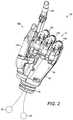
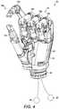
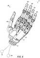
- FIGS. 2 to 8illustrate a “full hand” prosthesis according to the present invention in a number of operating modes
- FIG. 9is an illustrative example of a predetermined operating profile of the prosthesis with two input control signals
- FIG. 10is an illustrative example of a predetermined operating profile of the prosthesis with n input control signals.
- FIG. 11is a schematic diagram illustrating the operation of the prosthesis.
- FIGS. 1 to 8illustrate a prosthesis 10 according to the present invention.
- FIG. 1illustrates a prosthesis 10 a of the present invention fitted to a hand 1 of a partial-hand amputee.
- FIGS. 2 to 8illustrate the prosthesis 10 b of the present invention in a “full hand” configuration, which replaces the entire hand of an amputee.
- the prosthesis 10 ais fitted to a partial-hand amputee that is missing their thumb and forefinger.
- the remaining fingershave the reference number 2 .
- the prosthesis 10 acomprises two moveable digits 12 (thumb 12 a and forefinger 12 b ), which are examples of moveable components.
- the digits 12are attached to a body part 14 (hand chassis).
- the body part 14is attachable to the limb of the amputee in a known manner.
- the digits 12are arranged such that they can rotate and/or pivot with respect to the body part 14 .
- the digits 12are powered digits, such as those disclosed in WO 2007/063266 and WO 1995/24875.
- the digits 12are therefore mechanically operated digit members that are moved by an electric motor.
- the “full hand” prosthesis 10 bcomprises a body part 14 and five digits 12 (a thumb 12 a and four fingers 12 b ).
- the body part 14is rotatably attached to an attachment component 16 , which is used to attach the prosthesis 10 b to the wearer.
- the prosthesis 10 bis a replacement for the entire hand of the amputee.
- the finger digits 12 bmay pivot with respect to the body part 14 and, as is known in the art, flex and extend in the same manner as a human finger.
- the thumb digit 12 amay also pivot with respect to the body part 14 , as illustrated in FIG. 8 and explained further below.
- the body part 14itself may be a moveable component.
- the body part 14may rotate relative to the attachment component 16 , which is fitted to the wearer of the prosthesis.
- the body part 14may be motor driven with respect to the attachment component 16 . In this case, the body part 14 can perform the function of “wrist rotation” in the same manner as a human hand.
- the digits 12 of the prosthesis 10 a , 10 bare moveable with respect to the body part 14 such that the prosthesis 10 a , 10 b may provide a plurality of hand configurations, gestures and operations that are similar to those performed by a healthy human hand.
- FIGS. 1 and 4 to 7illustrate configurations of the prosthesis 10 a , 10 b operating in “pinch” mode, i.e. where the prosthesis 10 a , 10 b is operated to bring thumb digit 12 a and the forefinger digit 12 b into and out of contact with one another.
- FIG. 2illustrates a “pointing” gesture, where the forefinger digit 12 b is extended and the other finger digits 12 b are “closed”.
- FIG. 3illustrates a “grasp” configuration, where the prosthesis 10 b would be used to hold an object.
- FIG. 8illustrates a “waving” gesture, where the digits 12 are extended and the thumb digit 12 a is rotated away from the body part 14 .
- FIGS. 1 and 2The rotation of the entire thumb digit 12 a relative to the body part 14 can be seen from a comparison of FIGS. 1 and 2 , for example. Again, it should be noted that the body part 14 of FIGS. 2 to 8 may rotate relative to the attachment component 16 .
- the configurations and gestures illustrated in FIGS. 1 to 8may be considered to be the operating modes of the digits 12 of the prosthesis 10 a , 10 b .
- the rotation of the body part 14 relative to the attachment component 16may also be considered as an operating mode of the body part 14 of the prosthesis 10 b .
- the direction of rotation of the body part 14may be considered as an operating mode thereof.
- the prosthesis 10 a , 10 bmay thus be considered as having a plurality of operating modes.
- the operating modesare selected by the wearer of the prosthesis 10 a , 10 b depending on the operation they wish the prosthesis 10 a , 10 b to perform.
- the digits 12 of the prosthesis 10 a , 10 balso have a number of operating parameters. That is, the digits 12 have a number of operating conditions, such as their speed of movement, acceleration, deceleration, applied force, operating duration, amount of extension, amount of flexion and angle of rotation.
- the body part 14also includes a number of operating conditions, such as its speed of movement, acceleration, deceleration, applied force, operating duration and angle of rotation.
- the prosthesis 10 a , 10 bmay thus be considered as having a plurality of operating parameters. The operating parameters are selected by the wearer of the prosthesis 10 a , 10 b depending on the operation they wish the prosthesis 10 a , 10 b to perform.
- the prosthesis 10 a , 10 balso comprises an electronic device 18 which controls the operation of the digits 12 (and body part 14 for the “full hand” prosthesis 10 b ).
- the electronic device 18includes a processor and firmware (not shown) which together control the operation of the digits 12 .
- the electronic device 18may be located within the body part 14 , or alternatively be located on the wearer of the prosthesis 10 a , 10 b.
- the electronic device 18controls the operation of the digits 12 in response to one or more input control signals from the wearer.
- the input control signalsare derived from electrophysiological signals derived from the activity of, or from, surface electromyographic (EMG) or intramuscular activity of residual muscle actions of the wearer of the prosthesis.
- EMGsurface electromyographic
- the input control signalscome from two electromyographic (EMG) sensors 20 located, for example, on the thenar muscle group 22 and the hypothenar muscle group 24 .
- EMGelectromyographic
- the input control signalscome from two electromyographic (EMG) sensors (not shown) located on, for example, the muscle groups of the arm of the wearer.
- EMGelectromyographic
- the electrophysiological signals produced from the residual muscles to which the EMG sensors 20 are attachedare proportional to the activity of the muscles.
- the input control signals from the EMG sensors 20allow proportional control of the digits 12 of the prosthesis 10 a , 10 b . For example, this allows the wearer to proportionally control the speed of the operation of the digits 12 .
- the electronic device 18is operable to select both an operating mode of the digits 12 and at least one operating parameter of the digits 12 in response to an input command signal from the wearer of the prosthesis 10 a , 10 b .
- the electronic device 18is operable to select the “pinch” mode of FIG. 4 with a slow speed of movement and low pinch force of the digits 12 in response to a single input command signal from the wearer.
- Such an operation of the prosthesis 10 bmay be desired by the wearer when, for example, they wish to pick up a delicate object.
- the electronic device 18processes the input control signals from the EMG sensors 20 and produces the input command signal to control the digits 12 . It is important to note that the input command signal is a single signal which selects both the operating mode and the operating parameter(s) of the digits 12 of the prosthesis 10 a , 10 b.
- the electronic device 18includes a predetermined operating profile 26 of the prosthesis 10 a , 10 b .
- An example predetermined operating profile 26 of the prosthesis 10 a , 10 bis illustrated in FIGS. 9 and 10 .
- the predetermined operating profile 26provides for determination of the input command signal for the electronic device 18 in response to the input control signals from the EMG sensors 20 on the wearer of the prosthesis 10 a , 10 b.
- FIG. 9illustrates the predetermined operating profile of a prosthesis with two input signals
- FIG. 10illustrates the predetermined operating profile of a prosthesis with n input signals.
- FIG. 10is essentially a n dimensional version of the predetermined operating profile of FIG. 9 .
- the predetermined operating profile 26provides an input command signal P for the electronic device 18 in response to two input control signals p 1 , p 2 from the EMG sensors 20 on the wearer. As illustrated, the operating profile 26 is arranged into a number of areas 28 . Each area 28 represents an operating mode and operating parameter of the digits 12 of the prosthesis 10 a , 10 b . Therefore, the input control signals p 1 , p 2 from the EMG sensors 20 on the wearer determine which area 28 the point P lies, which, in turn, determines the input command signal P for the electronic device 18 .
- the operating profile 26includes four segments 30 a to 30 d .
- Each segment 30 a to 30 drepresents a different operating mode of the digits 12 of the prosthesis 10 a , 10 b and each area 28 a to 28 c represents a value or magnitude of an operating parameter of the digits 12 of the prosthesis 10 a , 10 b .
- Level 1 to mindicates, for example, the value or magnitude of the input control signals p 1 , p 2 .
- segment 30 acould represent the “pinch” mode ( FIGS. 4 and 5 ) of the digits 12 and area 28 a thereof could represent a minimum applied force of the digits 12 , i.e. a strong pinch.
- segment 30 dcould represent the “point” gesture mode ( FIG. 2 ) of the digits 12 and the area 28 c thereof could represent the speed of extension of the forefinger digit 12 b .
- the operating profile 26is configurable to meet the needs, demands and/or abilities of the wearer of the prosthesis 10 a , 10 b .
- the operating profile 26may include any number of segments 30 and areas 28 therein.
- the number of segments 30may be selected by the wearer depending on how many operating modes they wish to use.
- the number of segments 30may only be limited by the number of operating modes that the digits 12 have.
- the number of areas 28 in the segments 30may be chosen by the wearer depending on the number of options they wish to control the operating parameter(s) of the digits 12 .
- the use of two or more input control signals p 1 , p 2 , pndramatically increases the number of segments 30 and areas 28 available to the wearer of the prosthesis 10 a , 10 b .
- Each segment 30 and area 28is again representative of a different operating mode of the digits 12 of the prosthesis 10 a , 10 b and a value or magnitude of an operating parameter of the digits 12 of the prosthesis 10 a , 10 b .
- Using more input control signalsdramatically increases the control options and level of control offered to the wearer of the prosthesis 10 a , 10 b .
- the operating profile 26is configurable to meet the demands and/or abilities of the wearer of the prosthesis 10 a , 10 b.
- the operating profile 26is entirely configurable to meet the demands and abilities of the wearer. That is, it is not essential that the areas 28 of the operating profile 26 be arranged in any particular sequence or order, such as those illustrated and described above with reference to FIGS. 8 and 9 . It is, however, important that any given area 28 is representative of a chosen operating mode and operating parameter(s) selected by the wearer of the prosthesis 10 a , 10 b , and that the wearer of the prosthesis 10 a , 10 b knows the input signals p 1 , p 2 , etc. required to obtain the input command signal P for the electronic device 18 to control the digits 12 .
- the boundaries and the size of the areas 28may be configured depending on the needs, demands and abilities of the wearer, or by the wearer, clinician or intelligently by the electronic control device 18 .
- the electronic device 18includes the predetermined operating profile 26 .
- the predetermined operating profile 26is, for example, stored in the firmware of the electronic device 18 .
- the electronic device 18processes the input control signals p 1 , p 2 , . . . , pn, from the EMG sensors 20 on the wearer and determines the input command signal P from the operating profile 26 .
- the electronic device 18uses this input command signal P to control the operation of the digits 12 of the prosthesis 10 a , 10 b in the manner desired by the wearer.
- the input command signal Pis a single signal which results in selection of both the operating mode of the digits 12 of the prosthesis 10 a , 10 b and the operating parameters(s) of the digits 12 of the prosthesis 10 a , 10 b.
- the electronic device 18is also capable of pre-processing the input signals p 1 , p 2 , etc. to predict the intended input command signal P from the wearer of the prosthesis 10 a , 10 b .
- the pre-processing and prediction of the intended input command signal Pis carried out by the firmware and processor of the electronic device 18 .
- the electronic device 18is then capable of selecting both the operating mode of the digits 12 and the operating parameter(s) of the digits 12 on the basis of the predicted input command signal P′. This function is useful where the wearer of the prosthesis 10 a , 10 b repeats the same action on a regular basis. It also reduces the time taken select the operating mode of the digits 12 and the operating parameter(s) of the digits 12 . This “predictive” function can be switched on and off by the wearer as required.
- the electronic device 18is also capable of producing a feedback signal F to the wearer of the prosthesis 10 a , 10 b which is indicative of the operating mode of the digits 12 and the operating parameter(s) of the digits 12 (see FIG. 11 ).
- the feedback signal Fis an signal output by the electronic device 18 which may be communicated to the wearer visually, kinaesthetically, aurally or neurally.
- the feedback signal Fmay be communicated non-invasively to the wearer of the prosthesis via electro-tactile or vibro-tactile stimulation of the body skin.
- the electro-tactile or vibro-tactile stimulation to the body skinmay be provided at the forearm, shoulder, neck, or the like. This function is useful when, for example, the wearer cannot see the prosthesis 10 a , 10 b and cannot visually check that the intended operation is being carried out, i.e. that the input command signal is correct.
- the prosthesis 10 a , 10 bmay include a plurality of predetermined operating profiles 26 .
- Each predetermined operating profile 26may have its own arrangement of boundaries and size of the areas 28 , depending on the needs, demands and abilities of the wearer, clinician or intelligently by the electronic control device 18 .
- the electronic device 18is also capable of selecting a predetermined operating profile 26 from the plurality of predetermined operating profiles 26 that may be available.
- the electronic device 18is also capable of switching between two predetermined operating profiles 26 .
- the ability to switch between two, or more, predetermined operating profiles 26may be useful if the wearer of the prosthesis 10 a , 10 b becomes fatigued.
- the electronic device 18may therefore be configured to switch between a “normal” mode (a first predetermined operating profile) and a “fatigue” mode (a second predetermined operating profile).
- the switch between the two modesmay be decided by the wearer of the prosthesis 10 a , 10 b , or automatically decided by the electronic device 18 . If the switch between the two modes is decided by the wearer, the prosthesis 10 a , 10 b may be provided with a mechanical switch, or the like, to effect the selection of the desired predetermined operating profile 26 . If the switch between the two modes is decided by the electronic device 18 , the electronic device 18 may be provided with software to effect the selection of the desired predetermined operating profile 26 .
- the prosthesis 10 a , 10 bis configured such that it can measure the wearer's muscle fatigue. Fatigue measurement can be via monitoring the power spectrum of the electromyogram signal in time or in the frequency domain, e.g. a decrease in median power frequency can show increase in fatigue.
- Detection of the onset of fatiguecan be via many approaches, such as (i) if the signature of fatigue crosses a threshold, (ii) via supervised and unsupervised pattern recognition, such as neural networks, dimensionality reduction or clustering techniques and (iii) predictive control and time series nowcasting and forecasting.
- the process of adjusting for fatiguecan be either via recalibration by a clinician, or intelligently by an adaptive algorithm that can re-tune the predetermined operating profile 26 .
- Fatiguecan cause change in two parameters (or both) in the control system: (i) involuntary co-contraction of muscles that control the hand (In this case in FIG. 9 , boundaries of 30 a , 30 b , 30 c and 30 d will be adjusted (manually or intelligently) to minimise the effect of fatigue.) and (ii) reduction in the amplitude of the EMG (In this case in FIG. 9 , margins 28 a , 28 b , 28 c and 28 d and level 0 will be adjusted (manually or intelligently) to minimize the effect of fatigue.)
- the operation of the prosthesis 10 a , 10 bwill now be described.
- the prosthesis 10 a , 10 bcan be used by the wearer it is necessary to create an operating profile 26 for the wearer. While it is possible for the wearer to be provided with an existing operating profile, it is likely that the wearer will wish to create their own operating profile 26 , which, as described above, is based on their needs, abilities and available input control signal options.
- an important part of the creation of the operating profile 26is the wearer learning to use muscle groups, such as the thenar and hypothenar muscle groups, to produce the input command signal P.
- This activityinvolves the wearer using muscle groups (and potentially other input signal functions) which are non-intuitive to the wearer, i.e. there is no “intuitive” link between the input control signal and the desired function of the prosthesis 10 a , 10 b . That is, the movement of the digit(s) 12 can be initiated and controlled by, for example, a muscle (or a combination of n muscle activity) that does not necessarily control the function of that digit(s) before amputation, i.e. in healthy and able-bodied condition. For example, the thumb muscle can control the movement of the little finger or the wrist.
- an operating profile 26is created which the wearer is comfortable with and can easily use.
- the operating profile 26may be displayed on a computer screen in real time with the input control signals p 1 , p 2 , . . . , pn producing the input command signal P on the operating profile 26 .
- the input command signal P in this examplemay be considered as a cursor, which is moved around the operating profile 26 in dependence on the input control signals p 1 , p 2 , . . . , pn from the wearer.
- the cursorIn a rest position, i.e. where there is no input control signals p 1 , p 2 , . . . , pn from the wearer, the cursor is located at the origin O. To trigger the creation of an input command signal P the cursor should remain in an area 28 for a predetermined period. This period may be of the order of t milliseconds. With reference to FIG. 9 , if the cursor is moved to, for example, area 28 c , and stays there for less than t milliseconds, then quickly moves to an adjacent area 28 c , and remains there for t milliseconds, then two predetermined operations are triggered one after the other. In order to avoid such rapid selection of predetermined operations, t may be set to, for example, 200 milliseconds. The value of the period t may be selected on the requirements of the wearer.
- the prosthesis 10 a , 10 bmay be operated as follows: if the segment 30 d , for example, is associated with a “pinch” function and the wearer initiates a pinch function, in order to keep the pinch, the wearer should continue to produce input control signals p 1 , p 2 , . . . , pn in the same way to keep the cursor (input command signal P) in the same area 28 of the segment 30 . As soon as the wearer relaxes the controlling muscles, the cursor goes back to the origin O.
- the predetermined operating profile 26may have an absolute activity threshold (Level 0) and the prosthesis 10 a , 10 b may have two operational conditions.
- the operating profile 26may have an absolute activity threshold, i.e. there is a level 0. If the input control signals p 1 , p 2 , . . . , pn are such that the cursor is below the level 0 the whole hand electronics shuts off to save energy.
- the microprocessors of the electronic device 18wake up every x milliseconds to check the status. If the input control signals p 1 , p 2 , . . . , pn are such that the cursor is still below the level 0, the electronics remain switched off. If the input control signals p 1 , p 2 , . . . , pn are such that the cursor is above the level 0, the cursor is moved to this position.
- the gap between the level 0 position and the level 1 positionis also considered as an area 28 , as described above, and results in the selection of both an operating mode and operating parameter(s) of the digits 12 .
- This operating mode and operating parameter(s)may be, for example, a “hand open” configuration, a “thumb park” configuration, or a “predetermined natural hand configuration”. If the input control signals p 1 , p 2 , . . . , pn are such that the cursor goes through the gap between the level 0 and level 1 zones and stays there for t>200 milliseconds, the operating mode and operating parameter(s) are selected in the same manner as described above for areas 28 .
- the electronic device 18shuts off and the prosthesis 10 a , 10 b is maintained in the last configuration (i.e. operating mode and parameter(s)).
- the wearermay again take the cursor to the gap area between level 0 and level 1.
- the operating profile 26may not have an absolute activity threshold, i.e. there is no level 0.
- the gap between the origin O and level 1commands a predetermined operating mode and operating parameter(s) of the prosthesis 10 a , 10 b , e.g. “hand open”, “thumb park”, or a “predetermined natural hand configuration”, i.e. relax mode.
- the electronic device 18may still power down the electronics, as above.
- the only difference between the first and second operating conditionsis that in the second operating condition the hand does not keep the last gesture (operating mode and parameter(s)) when there are no input control signals p 1 , p 2 , . . . , pn, it opens regardless.
- input control signals p 1 , p 2 , . . . , pnare provided from the EMG sensors 20 on the wearer.
- the electronic device 18acquires and processes the input control signals p 1 , p 2 , . . . , pn.
- the processingmay include some signal processing, filtering etc., as is known in the art.
- the electronic device 18then uses the operating profile 26 to determine the input command signal P from the input control signals p 1 , p 2 , . . . , pn. Once the input command signal P has been determined the electronic device 18 controls the digits 12 in the desired manner.
- the electronic device 18selects both the operating mode of the digits 12 and the operating parameter(s) of the digits 12 in dependence of the input command signal P. Note: the electronic device 18 may be set to predict the intended input command signal P from the wearer. If this is the case the “Adaptive Decision Making” step is performed.
- FIG. 11also illustrates the operation of the feedback signal F to the wearer. It should be noted that the feedback signal F is fed back to the wearer in the “Feedback Generator” step.
- the prosthesis 10 a , 10 b of the present inventionprovides the wearer the flexibility of commanding a large number of different grip patterns (operating modes and parameters) by the provision of a single input command signal.
- a wearerif a wearer wishes to select or change grip pattern they typically have to perform a number of individual pulse or co-contraction stages, e.g. the wearer has to provide a first input command signal to select the operating mode of the digits and then has to provide a second input command signal to select the operating parameter of the digits.
- Operating a prosthesis in this manneris time consuming, frustrating and tiring.
- the prosthesis 10 a , 10 b of the present inventionsolves this problem by allowing the operating mode and operating parameter(s) to be selected by a single input command signal.
- prosthesis 10 ahas been illustrated and described above has having two digits (thumb digit 12 a and forefinger digit 12 b ), it should be appreciated that the prosthesis 10 a may have more than two digits 12 .
- the moveable componenthas mainly been referred to above as the digits 12 , is should be appreciated that the moveable component may include the body part 14 to which the digits 12 are attached.
- an orthosiscomprising: at least one moveable component, wherein the at least one moveable component has two or more operating modes and at least one operating parameter; and an electronic device operable to select both an operating mode of the at least one moveable component and at least one operating parameter of the at least one moveable component in response to an input command signal from the wearer of the prosthesis.
- the digitsmay be toes.
- the input control signals p 1 , p 2 etc.have been described above as coming from EMG control signals 20 , it should be appreciated that the input signals from the wearer of the prosthesis may be provided via one or more switches.
- the switchesmay be analogue or digital switches.
- the switchesmay be actuated by residual movement of the wearer of the prosthesis, wrist and/or shoulder movement of the wearer of the prosthesis, movement of the remnant digits and/or knuckles, or the like.
- the input signals from the wearer of the prosthesismay be provided by electrophysiological signals derived from the activity of, or from, surface electromyographic (EMG) and intramuscular activity of residual muscle actions of the wearer of the prosthesis, electroneurographic (ENG) activity of residual peripheral nerves of the wearer of the prosthesis, pressure sensitive resistors on the wearer of the prosthesis, signals derived from one or more neural implants in the wearer of the prosthesis implanted in the brain or spinal cord, EMG activity from reinnervated muscles, muscles of the feet and/or chest, or the like.
- EMGsurface electromyographic
- ENGelectroneurographic
- the input signals from the wearer of the prosthesismay be provided by non-electrophysiological signals derived from the activity pressure or bend sensitive resistors on the wearer of the body to capture any residual movement digits, wrist, elbow or shoulder of the wearer of the prosthesis or the like.
- the input signals from the wearer of the prosthesismay be provided by signals derived from the activity of, or from, electromyographic (EMG) activity of hand muscle actions, or residual muscle actions, of the wearer of the prosthesis recorded non-invasively from the skin or invasively from deep muscular structures.
- EMGelectromyographic
- the prosthesismay be controlled by the activity of any combination of intrinsic and extrinsic hand muscle group, such as muscles in the thenar and hypothenar muscles, the interossei muscles originating between the metacarpal bones, the long flexors and extensors in the forearm, e.g. extensor pollicis longus muscle, extensor/flexor indicis muscle, or the like.
- intrinsic and extrinsic hand muscle groupsuch as muscles in the thenar and hypothenar muscles, the interossei muscles originating between the metacarpal bones, the long flexors and extensors in the forearm, e.g. extensor pollicis longus muscle, extensor/flexor indicis muscle, or the like.
- the input control signals p 1 , p 2 etc.may be produced from any combination of the above-referenced input signal options.
- the electronic devicehas been described above as being operable to select both an operating mode and an operating parameter(s) of the digits in response to an input command signal from the wearer, it should be appreciated that the electronic device may be operable to select one or more sequences of operating modes and operating parameter(s) of the digits in response to an input command signal from the wearer. This would allow the wearer to perform, for example, a number of tasks in a chosen order, such as the gesture point of FIG. 2 followed by the gesture wave of FIG. 8 .
Landscapes
- Health & Medical Sciences (AREA)
- Transplantation (AREA)
- Vascular Medicine (AREA)
- Life Sciences & Earth Sciences (AREA)
- Oral & Maxillofacial Surgery (AREA)
- Engineering & Computer Science (AREA)
- Biomedical Technology (AREA)
- Heart & Thoracic Surgery (AREA)
- Orthopedic Medicine & Surgery (AREA)
- Cardiology (AREA)
- Animal Behavior & Ethology (AREA)
- General Health & Medical Sciences (AREA)
- Public Health (AREA)
- Veterinary Medicine (AREA)
- Prostheses (AREA)
- User Interface Of Digital Computer (AREA)
Abstract
Description
- receiving at least one input control signal from the wearer of the prosthesis;
- comparing the at least one input control signal with an operating profile stored in the electronic control device in order to determine a desired operating mode and operating parameter; and
- instructing the moveable component to move in accordance with the desired operating mode and operating parameter.
- storing input control signals received so as to establish an input control signal pattern; and
- predicting a desired operating mode and operating parameter based upon the input control signal pattern upon receiving the at least one control signal from the wearer of the prosthesis.
- at least one moveable component, the component having two or more operating modes and at least one operating parameter; and
- an electronic control device storing an operating profile;
- wherein the control device receives at least one input control signal from a wearer of the prosthesis, compares the at least one input control signal with the operating profile to determine a desired operating mode and operating parameter for the component, and instructs the component to move in accordance with the desired operating mode and operating parameter.
- at least one moveable component, wherein the at least one moveable component has two or more operating modes and at least one operating parameter; and
- an electronic device operable to select both an operating mode of the at least one moveable component and at least one operating parameter of the at least one moveable component in response to an input command signal from the wearer of the prosthesis.
- providing the electronic device with an input command signal from the wearer of the prosthesis; and
- using the electronic device to select both an operating mode of the at least one moveable component and at least one operating parameter of the at least one moveable component in response to the input command signal from the wearer of the prosthesis.
Claims (16)
Applications Claiming Priority (3)
| Application Number | Priority Date | Filing Date | Title |
|---|---|---|---|
| GBGB1302025.0AGB201302025D0 (en) | 2013-02-05 | 2013-02-05 | Improvements in or relating to prosthetics |
| GB1302025.0 | 2013-02-05 | ||
| PCT/GB2014/050331WO2014122455A1 (en) | 2013-02-05 | 2014-02-05 | Improvements in or relating to prosthetics |
Related Parent Applications (1)
| Application Number | Title | Priority Date | Filing Date |
|---|---|---|---|
| PCT/GB2014/050331A-371-Of-InternationalWO2014122455A1 (en) | 2013-02-05 | 2014-02-05 | Improvements in or relating to prosthetics |
Related Child Applications (1)
| Application Number | Title | Priority Date | Filing Date |
|---|---|---|---|
| US16/811,638ContinuationUS11890208B2 (en) | 2013-02-05 | 2020-03-06 | Multi-modal upper limb prosthetic device control using myoelectric signals |
Publications (2)
| Publication Number | Publication Date |
|---|---|
| US20150374515A1 US20150374515A1 (en) | 2015-12-31 |
| US10610385B2true US10610385B2 (en) | 2020-04-07 |
Family
ID=47988743
Family Applications (2)
| Application Number | Title | Priority Date | Filing Date |
|---|---|---|---|
| US14/765,638ActiveUS10610385B2 (en) | 2013-02-05 | 2014-02-05 | Multi-modal upper limb prosthetic device control using myoelectric signals |
| US16/811,638Active2035-05-28US11890208B2 (en) | 2013-02-05 | 2020-03-06 | Multi-modal upper limb prosthetic device control using myoelectric signals |
Family Applications After (1)
| Application Number | Title | Priority Date | Filing Date |
|---|---|---|---|
| US16/811,638Active2035-05-28US11890208B2 (en) | 2013-02-05 | 2020-03-06 | Multi-modal upper limb prosthetic device control using myoelectric signals |
Country Status (4)
| Country | Link |
|---|---|
| US (2) | US10610385B2 (en) |
| EP (1) | EP2953588A1 (en) |
| GB (1) | GB201302025D0 (en) |
| WO (1) | WO2014122455A1 (en) |
Cited By (11)
| Publication number | Priority date | Publication date | Assignee | Title |
|---|---|---|---|---|
| US10973660B2 (en) | 2017-12-15 | 2021-04-13 | Touch Bionics Limited | Powered prosthetic thumb |
| US11083600B2 (en) | 2014-02-25 | 2021-08-10 | Touch Bionics Limited | Prosthetic digit for use with touchscreen devices |
| US11185426B2 (en) | 2016-09-02 | 2021-11-30 | Touch Bionics Limited | Systems and methods for prosthetic wrist rotation |
| US11234842B2 (en) | 2014-05-09 | 2022-02-01 | Touch Bionics Limited | Systems and methods for controlling a prosthetic hand |
| US11259941B2 (en) | 2011-08-18 | 2022-03-01 | Touch Bionics Limited | Prosthetic feedback apparatus and method |
| US11357646B2 (en) | 2014-10-03 | 2022-06-14 | Touch Bionics Limited | Wrist device for a prosthetic limb |
| US11464654B2 (en) | 2014-02-04 | 2022-10-11 | Rehabilitation Institute Of Chicago | Modular and lightweight myoelectric prosthesis components and related methods |
| US11547581B2 (en) | 2018-12-20 | 2023-01-10 | Touch Bionics Limited | Energy conservation of a motor-driven digit |
| US11890208B2 (en) | 2013-02-05 | 2024-02-06 | Touch Bionics Limited | Multi-modal upper limb prosthetic device control using myoelectric signals |
| US11931270B2 (en) | 2019-11-15 | 2024-03-19 | Touch Bionics Limited | Prosthetic digit actuator |
| US12115087B2 (en) | 2020-11-03 | 2024-10-15 | Touch Bionics Limited | Sensor for prosthetic control |
Families Citing this family (20)
| Publication number | Priority date | Publication date | Assignee | Title |
|---|---|---|---|---|
| ITPI20130004A1 (en) | 2013-01-16 | 2014-07-17 | Machinale S R L Fab | PROSTHETIC STRUCTURE FOR HAND AMPUTATION |
| US11229789B2 (en) | 2013-05-30 | 2022-01-25 | Neurostim Oab, Inc. | Neuro activator with controller |
| CA2913074C (en) | 2013-05-30 | 2023-09-12 | Graham H. Creasey | Topical neurological stimulation |
| US11077301B2 (en) | 2015-02-21 | 2021-08-03 | NeurostimOAB, Inc. | Topical nerve stimulator and sensor for bladder control |
| EP3506857B1 (en) | 2016-09-02 | 2025-07-09 | Touch Bionics Limited | Systems and methods for prosthetic wrist rotation |
| AU201711357S (en)* | 2016-09-08 | 2017-05-22 | 5Th Element Ltd | An automated hand |
| CN111601636A (en) | 2017-11-07 | 2020-08-28 | Oab神经电疗科技公司 | Non-invasive neural activator with adaptive circuit |
| GB201815632D0 (en) | 2018-09-25 | 2018-11-07 | Objectiv X Ltd | A mechanical hand |
| USD890343S1 (en)* | 2018-09-26 | 2020-07-14 | Covvi Limited | Prosthetic hand |
| WO2020106728A1 (en) | 2018-11-19 | 2020-05-28 | The Regents Of The University Of Colorado, A Body Corporate | Prosthetic partial fingers |
| DE102019101143B4 (en)* | 2019-01-17 | 2020-08-06 | Otto Bock Healthcare Products Gmbh | Method for controlling an orthotic or prosthetic device and orthetic or prosthetic device |
| CN109710081B (en)* | 2019-02-20 | 2024-11-22 | 杭州老板电器股份有限公司 | Gesture sensing test device and method |
| CN113853181A (en) | 2019-04-10 | 2021-12-28 | 塔驰仿生有限公司 | Prosthetic fingers with articulated links |
| WO2020264214A1 (en) | 2019-06-26 | 2020-12-30 | Neurostim Technologies Llc | Non-invasive nerve activator with adaptive circuit |
| CN110731842B (en)* | 2019-09-20 | 2021-11-19 | 上海健康医学院 | Pneumatic muscle driven thumb device for smart hand |
| CN114728161A (en) | 2019-12-16 | 2022-07-08 | 神经科学技术有限责任公司 | Non-invasive neural activator with boosted charge delivery |
| EP4042982B1 (en) | 2021-02-10 | 2024-05-29 | Point Designs LLC | Prosthetic thumb device |
| GB2615785B (en)* | 2022-02-18 | 2024-07-10 | L Univ Ta Malta | Prosthetic hand device and method of control |
| CN114536380B (en)* | 2022-04-26 | 2022-09-06 | 中国科学院自动化研究所 | Five-freedom-degree full-drive humanoid thumb and humanoid dexterous hand |
| CN114536381B (en)* | 2022-04-26 | 2022-09-06 | 中国科学院自动化研究所 | Human-simulated five-finger dexterous hand |
Citations (220)
| Publication number | Priority date | Publication date | Assignee | Title |
|---|---|---|---|---|
| DE309367C (en) | ||||
| US1507682A (en) | 1924-03-17 | 1924-09-09 | Livingston Artificial Limb Com | Artificial limb |
| GB326970A (en) | 1929-02-26 | 1930-03-27 | Joseph Willie Levasseur | Improvements in artificial hands |
| US2445711A (en) | 1946-06-17 | 1948-07-20 | Fitch And Sons Inc | Mechanical movement |
| GB607001A (en) | 1946-01-23 | 1948-08-24 | Arthur Appleby Moller | Improvements in artificial limbs |
| US2477463A (en) | 1945-09-28 | 1949-07-26 | Otterman Joyce | Artificial arm |
| US2482555A (en) | 1946-01-01 | 1949-09-20 | Otterman Joyce | Artificial limb |
| US2508156A (en) | 1948-05-20 | 1950-05-16 | Gillman Harry | Method of making artificial hands and replicas of other objects |
| US2516791A (en) | 1948-04-06 | 1950-07-25 | Northrop Aircraft Inc | Artificial arm |
| US2592842A (en) | 1948-07-10 | 1952-04-15 | Samuel W Alderson | Shoulder harness for artificial arms |
| US2669727A (en) | 1951-07-24 | 1954-02-23 | Opuszenski Theodore | Artificial hand |
| US2983162A (en) | 1958-12-10 | 1961-05-09 | United Shoe Machinery Corp | Strain wave gearing-spring preloading |
| US3406584A (en) | 1967-08-21 | 1968-10-22 | Roantree Electro Mech Corp | Differential roller nut |
| US3509583A (en) | 1965-09-09 | 1970-05-05 | Bendix Corp | Electro-mechanical hand having tactile sensing means |
| US3683423A (en) | 1971-01-19 | 1972-08-15 | Russell S Crapanzano | Gravity activated prosthetic device |
| US3751995A (en) | 1972-06-02 | 1973-08-14 | Usm Corp | Sequential rotary and linear actuating mechanism |
| US3837010A (en) | 1972-03-16 | 1974-09-24 | Parke Davis & Co | Prosthetic elbow with resilient locking assembly |
| US3866246A (en) | 1972-11-14 | 1975-02-18 | Us Navy | Shoulder disarticulation prosthetic system |
| GB1386942A (en) | 1973-01-19 | 1975-03-12 | Steeper Roehampton Ltd Hugh | Artificial limbs |
| US3883900A (en) | 1973-09-07 | 1975-05-20 | Liberty Mutual Insurance Compa | Bioelectrically controlled prosthetic member |
| US3922930A (en) | 1974-12-23 | 1975-12-02 | Nasa | Remotely operable articulated manipulator |
| DE2434834A1 (en) | 1974-07-19 | 1976-02-12 | Werner Dr Ing Ohm | GEAR MOTOR |
| US4030141A (en)* | 1976-02-09 | 1977-06-21 | The United States Of America As Represented By The Veterans Administration | Multi-function control system for an artificial upper-extremity prosthesis for above-elbow amputees |
| JPS5311456A (en) | 1976-07-15 | 1978-02-01 | Agency Of Ind Science & Technol | Thumb driving mechanism in artificial fingers |
| GB1510298A (en) | 1976-02-25 | 1978-05-10 | Messerschmitt Boelkow Blohm | Artificial hands |
| JPS5394693A (en) | 1977-01-25 | 1978-08-18 | Toshiba Silicone | Method and apparatus for producing silicone coated stretchable cloth article |
| US4197592A (en) | 1976-09-17 | 1980-04-15 | Cluett, Peabody & Co., Inc. | Sport glove |
| GB1585256A (en) | 1977-07-01 | 1981-02-25 | Steeper Roehampton Ltd Hugh | Device for applying a controlled torque |
| GB2067074A (en) | 1979-12-21 | 1981-07-22 | Steeper Hugh Ltd | Silicon rubber covers for external prosthesis |
| US4398110A (en) | 1982-05-05 | 1983-08-09 | Westinghouse Electric Corp. | Harmonic electric actuator |
| GB2146406A (en) | 1983-09-08 | 1985-04-17 | Univ Southampton | Actuator for converting rotary to oscillatory motion |
| EP0145504A2 (en) | 1983-12-15 | 1985-06-19 | Wright State University | Hand control system |
| US4577127A (en) | 1983-12-21 | 1986-03-18 | Westinghouse Electric Corp. | Lightweight electric robotic actuator |
| US4623354A (en) | 1984-10-22 | 1986-11-18 | Northwestern University | Myoelectrically controlled artificial hand |
| EP0219478A1 (en) | 1985-10-15 | 1987-04-22 | Centri Gummifabrik Ab | Artificial hand |
| US4678952A (en) | 1985-08-13 | 1987-07-07 | Intelledex Incorporated | Sealed joint for a robot and the like |
| EP0256643A2 (en) | 1986-07-11 | 1988-02-24 | Hugh Steeper Limited | Surface and Bulk Modification of plasticized materials |
| US4808187A (en) | 1987-10-05 | 1989-02-28 | Iowa State University Research Foundation, Inc. | Tactile stimulus receptor for a hand prosthesis |
| US4813303A (en) | 1984-08-31 | 1989-03-21 | Mandreles, Inc. | Power drive speed reducer |
| US4822238A (en) | 1986-06-19 | 1989-04-18 | Westinghouse Electric Corp. | Robotic arm |
| US4955918A (en) | 1989-05-30 | 1990-09-11 | University Of Southern California | Artificial dexterous hand |
| US4960425A (en) | 1987-05-27 | 1990-10-02 | Mentor Corporation | Textured surface frosthesis implants |
| US4990162A (en) | 1988-03-21 | 1991-02-05 | Children's Hospital At Stanford | Rotary hand prosthesis |
| US5020162A (en) | 1988-04-01 | 1991-06-04 | Baxter International Inc. | Glove |
| US5062673A (en) | 1988-12-28 | 1991-11-05 | Kabushiki Kaisha Toyota Chuo Kenkyusho | Articulated hand |
| US5088125A (en) | 1987-04-21 | 1992-02-18 | Smith & Nephew Associated Companies Plc | Gloves |
| EP0484173A2 (en) | 1990-11-01 | 1992-05-06 | Westinghouse Electric Corporation | Robotic arm for maintaining a tool in a desired orientation |
| US5133775A (en) | 1991-04-29 | 1992-07-28 | Sen Jung Chen | Covering device for an artificial limb |
| US5246463A (en) | 1992-02-21 | 1993-09-21 | Giampapa Vincent C | Sensate and spacially responsive prosthesis |
| US5252102A (en) | 1989-01-24 | 1993-10-12 | Electrobionics Corporation | Electronic range of motion apparatus, for orthosis, prosthesis, and CPM machine |
| US5255188A (en) | 1991-09-16 | 1993-10-19 | Jace Systems, Inc. | Universal controller for continuous passive motion devices |
| US5387245A (en) | 1991-12-23 | 1995-02-07 | Fay; John N. | Inflatable prosthesis liner |
| US5413611A (en) | 1992-07-21 | 1995-05-09 | Mcp Services, Inc. | Computerized electronic prosthesis apparatus and method |
| US5413454A (en) | 1993-07-09 | 1995-05-09 | Movsesian; Peter | Mobile robotic arm |
| JPH07174631A (en) | 1993-12-16 | 1995-07-14 | Kao Corp | Skin colorimetric method and spectral reflectance spectrum estimation method |
| WO1995024875A1 (en) | 1994-03-12 | 1995-09-21 | Royal Infirmary Of Edinburgh Nhs Trust | Hand prosthesis |
| US5498472A (en) | 1993-06-22 | 1996-03-12 | Kombi Ltd. | Non-laminated differential wind barrier fabrics and garments |
| US5501498A (en) | 1988-08-31 | 1996-03-26 | The Trustees Of The University Of Pennsylvania | Methods and apparatus for mechanically intelligent grasping |
| WO1996023643A1 (en) | 1995-02-02 | 1996-08-08 | Baxter International Inc. | A process for making a glove having a polyurethane coating |
| US5581166A (en) | 1986-02-18 | 1996-12-03 | Robotics Research Corporation | Industrial robot with servo |
| US5785960A (en) | 1997-03-19 | 1998-07-28 | Elizabeth Arden Co., Division Of Conopco, Inc. | Method and system for customizing dermatological foundation products |
| US5852675A (en) | 1995-04-14 | 1998-12-22 | Kiyoshi Matsuo | Color chart for image correction and method of color correction |
| US5851194A (en) | 1995-07-17 | 1998-12-22 | Fratrick; Richard A. | Quick release mechanism for orthopedic limb brace |
| US5888213A (en)* | 1997-06-06 | 1999-03-30 | Motion Control, Inc. | Method and apparatus for controlling an externally powered prosthesis |
| US5900714A (en) | 1996-11-08 | 1999-05-04 | International Rectifier Corporation | Circuit for sensing motor load current |
| EP0947899A2 (en) | 1998-04-03 | 1999-10-06 | A-Pear Biometric Replications Inc. | Methods for making prosthetic surfaces |
| EP0968695A2 (en) | 1998-06-29 | 2000-01-05 | Otto Bock Orthopädische Industrie Besitz- und Verwaltungs-Kommanditgesellschaft | Cosmetic stocking |
| WO2000025840A1 (en) | 1998-11-05 | 2000-05-11 | Allegiance Corporation | Powder-free gloves with a silicone impregnated polyurethane inner coating |
| DE19854762A1 (en) | 1998-11-27 | 2000-06-15 | Marc Franke | Artificial hand with two or more fingers for picking up objects includes distal finger section connected by tilting movement to medial section by distal articulated joint, and medial to proximal by medial joint |
| US6111973A (en) | 1997-05-29 | 2000-08-29 | Holt; Kenneth Dale | Method for producing color-comparable photographs with fleshtone color selections for prosthetic fabrication |
| EP1043003A1 (en) | 1999-03-22 | 2000-10-11 | Advanced Control Research Ltd. | Prosthetic limbs |
| WO2000069375A1 (en) | 1999-05-19 | 2000-11-23 | Rutgers, The State University Of New Jersey | Dexterous prosthetic hand |
| WO2001004838A1 (en) | 1999-07-07 | 2001-01-18 | Unilever Plc | A system for colour cosmetic selection |
| US6175962B1 (en) | 1988-10-17 | 2001-01-23 | Gary Karlin Michelson | Surgical glove |
| JP2001082913A (en) | 1999-09-09 | 2001-03-30 | Univ Tokyo | Angle detection sensor |
| US6223615B1 (en) | 1997-06-17 | 2001-05-01 | Robert Bosch Gmbh | Actuating electromotor for technical devices, in particular in motor vehicles |
| US6244873B1 (en)* | 1998-10-16 | 2001-06-12 | At&T Corp. | Wireless myoelectric control apparatus and methods |
| GB2357725A (en) | 1999-12-02 | 2001-07-04 | Blatchford & Sons Ltd | Silicone cosmesis |
| US20010023058A1 (en) | 1997-01-02 | 2001-09-20 | Jung Wayne D. | Apparatus and method for measuring optical characteristics of teeth |
| JP2001299448A (en) | 2000-04-21 | 2001-10-30 | Shiseido Co Ltd | Make-up counseling device |
| US6344062B1 (en) | 1999-03-18 | 2002-02-05 | The State University Rutgers | Biomimetic controller for a multi-finger prosthesis |
| US20020016631A1 (en) | 2000-05-03 | 2002-02-07 | Marchitto Kevin S. | Prosthesis and method of making |
| US6361570B1 (en) | 1997-10-24 | 2002-03-26 | Lothian Primary Care Nhs Trust | Upper limb prosthesis |
| JP2002131135A (en) | 2000-10-20 | 2002-05-09 | Kao Corp | Reference color chart and makeup simulation device |
| WO2002049534A2 (en) | 2000-12-19 | 2002-06-27 | Alorman Advanced Medical Technologies, Ltd. | Method for controlling multi-function myoelectric prothesis |
| DE10105814C1 (en) | 2001-10-20 | 2002-09-12 | Oechsler Ag | Harmonic drive comprises a housing-independent support ring mounted on the front side of a base plate and enclosed by a housing cover |
| US20020135241A1 (en) | 2001-02-19 | 2002-09-26 | Yukitoshi Kobayashi | Actuator having a wave gear reduction drive |
| US20020143405A1 (en)* | 2001-03-30 | 2002-10-03 | I.N.A.I.L. Centro Per La Sperimentazione Ed Applicazione Di Protesi E Presidi Ortopedici | System for the control and monitoring of functional devices for the disabled with energy from outside the body and a method for the remote control thereof |
| JP2002310242A (en) | 2001-04-17 | 2002-10-23 | Murakami Corp | Bearing structure of worm gear |
| US20030036805A1 (en) | 2001-07-17 | 2003-02-20 | Martin Senior | Gripper device |
| WO2003017877A1 (en) | 2001-08-27 | 2003-03-06 | Bergomed Ab | Device at a finger prosthesis |
| WO2003017878A1 (en) | 2001-08-27 | 2003-03-06 | Bergomed Ab | Mechanical hand with the gripping ability of the human hand |
| WO2003017880A1 (en) | 2001-08-27 | 2003-03-06 | Bergomed Ab | A thumb at a mechanical hand |
| JP2003134526A (en) | 2001-10-19 | 2003-05-09 | Univ Waseda | Apparatus and method for color reproduction |
| US6660043B2 (en) | 2002-04-16 | 2003-12-09 | National Institute Of Advanced Industrial Science And Technology | Artificial hand |
| US20040002672A1 (en) | 2002-06-28 | 2004-01-01 | Carlson J. Martin | Adjustable mounting housing for prosthetic ankle flexure joint |
| DE20315575U1 (en) | 2003-10-10 | 2004-01-15 | medi Bayreuth Weihermüller & Voigtmann GmbH & Co. KG | Liner or knee cap for stumps of amputated arms or legs comprises sleeve of flexible silicone, polyurethane or thermoplastic elastomer with outer coating of polymer which assists sliding |
| JP2004073802A (en) | 2002-08-20 | 2004-03-11 | Forest Denki Kk | Multipurpose measuring unit for skin |
| US20040078299A1 (en) | 2002-01-31 | 2004-04-22 | Kathleen Down-Logan | Portable color and style analysis, match and management system |
| US20040078091A1 (en) | 2002-10-15 | 2004-04-22 | Elkins Jeffrey L. | Foot-operated controller |
| JP2004224280A (en) | 2003-01-24 | 2004-08-12 | Koyo Seiko Co Ltd | Electric power steering device |
| US6786112B2 (en) | 2001-02-08 | 2004-09-07 | Oechsler Ag | Harmonic drive with crowned drive ring |
| US20040181289A1 (en) | 2002-08-22 | 2004-09-16 | Stephane Bedard | Actuated prosthesis for amputees |
| US20040182125A1 (en) | 2001-03-22 | 2004-09-23 | Mclean Lyle John | Method and apparatus for manufacture of a forged rack |
| US20050021154A1 (en) | 2001-08-27 | 2005-01-27 | Stellan Brimalm | Drive device for a finger prosthesis |
| US20050021155A1 (en) | 2001-08-27 | 2005-01-27 | Stellan Brimalm | Device at a hand prosthesis |
| US20050093997A1 (en) | 2003-10-30 | 2005-05-05 | Dalton Dan L. | System and method for dual white balance compensation of images |
| US20050101693A1 (en) | 2003-11-06 | 2005-05-12 | Ohio Willow Wood Company | Gel and cushioning devices |
| US20050192677A1 (en) | 2004-02-12 | 2005-09-01 | Ragnarsdottir Heidrun G. | System and method for motion-controlled foot unit |
| EP1617103A1 (en) | 2003-04-24 | 2006-01-18 | Toyota Jidosha Kabushiki Kaisha | Planetary differential screw-type rotational motion/linear motion converter |
| US20060029909A1 (en) | 2004-08-05 | 2006-02-09 | Kaczkowski Michael D | Method and apparatus for producing objective color references for color matching or identifying |
| US20060054782A1 (en) | 2004-08-25 | 2006-03-16 | Olsen Richard I | Apparatus for multiple camera devices and method of operating same |
| WO2006058190A2 (en) | 2004-11-23 | 2006-06-01 | Color Savvy Systems Limited | Method for deriving consistent, repeatable color measurements from data provided by a digital imaging device |
| WO2006069264A1 (en) | 2004-12-22 | 2006-06-29 | össur hf | Systems and methods for processing limb motion |
| CN1803413A (en) | 2006-01-20 | 2006-07-19 | 哈尔滨工业大学 | Thumb mechanism of underactuated self-adaptive hand prosthesis |
| US20060158146A1 (en) | 2004-12-03 | 2006-07-20 | Sharp Kabushiki Kaisha | Robot hand |
| US20060167564A1 (en) | 2005-01-10 | 2006-07-27 | Flaherty J C | Limb and digit movement system |
| WO2006078432A2 (en) | 2005-01-18 | 2006-07-27 | Cyberkinetics Neurotechnology Systems, Inc. | Biological interface system with automated configuration |
| WO2006086504A2 (en) | 2005-02-09 | 2006-08-17 | Alfred E. Mann Institute For Biomedical Engineering At The University Of Southern California | Method and system for training adaptive control of limb movement |
| WO2006092604A2 (en) | 2005-03-02 | 2006-09-08 | Charles Conrad Carroll | Skin colour matching method and system |
| US20060212129A1 (en) | 2005-03-16 | 2006-09-21 | Lake Joseph C | Partial hand prosthesis |
| US20060229755A1 (en) | 2005-04-12 | 2006-10-12 | Rehabilitation Institute Of Chicago | Method for creating covers for prosthetic devices and other dynamic supporting members |
| US20060251408A1 (en) | 2004-01-23 | 2006-11-09 | Olympus Corporation | Image processing system and camera |
| US7144430B2 (en) | 2002-07-12 | 2006-12-05 | Motion Control, Inc. | Wrist device for use with a prosthetic limb |
| US20070032884A1 (en) | 2005-06-17 | 2007-02-08 | Ada Technologies, Inc. | Cable lock device for prosthetic and orthotic devices |
| US20070058860A1 (en) | 2005-09-09 | 2007-03-15 | Michael Harville | Method and system for skin color estimation from an image |
| US20070061111A1 (en) | 1998-07-09 | 2007-03-15 | Jung Wayne D | Apparatus and method for measuring optical characteristics of an object |
| US20070071314A1 (en) | 2005-09-09 | 2007-03-29 | Nina Bhatti | Capture and systematic use of expert color analysis |
| WO2007063266A1 (en) | 2005-11-29 | 2007-06-07 | Touch Emas Limited | Prostheses with mechanically operable digit members |
| WO2007076764A2 (en) | 2005-12-20 | 2007-07-12 | Otto Bock Healthcare Ip Gmbh & Co. Kg | Hand prosthesis comprising two drive devices |
| WO2007076765A2 (en) | 2005-12-20 | 2007-07-12 | Otto Bock Healthcare Ip Gmbh & Co. Kg | Hand prosthesis with fingers that can be aligned in an articulated manner |
| US7243569B2 (en) | 2001-10-02 | 2007-07-17 | Kabaya Industry Co., Ltd. | Power transmission device, electric power steering device, and method of producing the same |
| US20070175681A1 (en) | 2006-01-18 | 2007-08-02 | General Electric Company | Vehicle and method of assembling same |
| US20070230832A1 (en) | 2006-04-03 | 2007-10-04 | Pfu Limited | Medicine bag and color reproduction system |
| WO2007127973A2 (en) | 2006-04-28 | 2007-11-08 | College Park Industries, Inc. | Prosthetic sensing systems and methods |
| US20070260328A1 (en) | 2006-05-03 | 2007-11-08 | Otto Bock Healthcare Ip Gmbh & Co. Kg | Prosthetic joint |
| WO2007126854A2 (en) | 2006-03-28 | 2007-11-08 | Alfred E. Mann Institute For Biomedical Engineering At The University Of Southern California | Biomimetic tactile sensor |
| US7316304B2 (en) | 2005-06-10 | 2008-01-08 | Warn Industries, Inc. | Four-wheel drive center disconnect electric actuator |
| US7316795B1 (en) | 2004-03-02 | 2008-01-08 | Stefan Johannes Knauss | Method for overmolding a painted silicone rubber human extremity prosthesis |
| US20080058668A1 (en)* | 2006-08-21 | 2008-03-06 | Kaveh Seyed Momen | Method, system and apparatus for real-time classification of muscle signals from self-selected intentional movements |
| WO2008044052A1 (en) | 2006-10-12 | 2008-04-17 | Touch Emas Limited | Process for forming coverings |
| WO2008044207A2 (en) | 2006-10-13 | 2008-04-17 | Koninklijke Philips Electronics N.V. | Switchable joint constraint system |
| US7370896B2 (en) | 2003-12-30 | 2008-05-13 | Strider Labs, Inc. | Robotic hand with extendable palm |
| GB2444679A (en) | 2005-10-11 | 2008-06-11 | Matsushita Electric Industrial Co Ltd | Motion assistance apparatus and method of assisting motion |
| US20080146981A1 (en) | 2006-07-21 | 2008-06-19 | Simbex Llc | Dynamic body protector |
| WO2008092695A1 (en) | 2007-02-01 | 2008-08-07 | Otto Bock Healthcare Products Gmbh | Prosthetic finger |
| WO2008098072A2 (en) | 2007-02-06 | 2008-08-14 | Hanger Orthopedic Group Inc. | System and method for using a digit to position a prosthetic or orthotic device |
| WO2008098059A2 (en) | 2007-02-06 | 2008-08-14 | Deka Integrated Solutions Corp. | Method and apparatus for control of a prosthetic |
| US20080260218A1 (en) | 2005-04-04 | 2008-10-23 | Yoav Smith | Medical Imaging Method and System |
| WO2009011682A1 (en) | 2007-07-19 | 2009-01-22 | Northeastern University | Gear bearing drive |
| US7640680B1 (en) | 2004-09-20 | 2010-01-05 | Castro Ernesto G | Pedorthic systems |
| US20100016990A1 (en) | 2008-07-21 | 2010-01-21 | Kulite Semiconductor Products, Inc. | Microelectromechanical system (MEMS) employing wireless transmission for providing sensory signals |
| WO2010018358A2 (en) | 2008-08-11 | 2010-02-18 | Rslsteeper Group Limited | A device resembling a part of the human body which is able to be actuated |
| US20100116078A1 (en) | 2008-11-12 | 2010-05-13 | Samsung Electronics Co., Ltd. | Electrical connecting device of joint unit and robot having the same |
| WO2010051798A1 (en) | 2008-11-08 | 2010-05-14 | Stefan Schulz | Finger element |
| US20100274365A1 (en) | 2007-02-06 | 2010-10-28 | Deka Products Limited Partnership | Arm prosthetic device |
| US7823475B2 (en) | 2005-12-28 | 2010-11-02 | Harmonic Drive Systems Inc. | Sealed worm gear type finger joint unit |
| WO2010149967A1 (en) | 2009-06-24 | 2010-12-29 | Touch Emas Limited Et Al | Method of controlling a prosthesis |
| WO2011001136A2 (en) | 2009-07-02 | 2011-01-06 | Rslsteeper Group Limited | Prosthetic apparatus |
| WO2011022569A1 (en) | 2009-08-20 | 2011-02-24 | Vanderbilt University | Jointed mechanical devices |
| WO2011036473A1 (en) | 2009-09-25 | 2011-03-31 | Touch Emas Limited | Prosthetic apparatus and control method |
| WO2011036626A2 (en) | 2009-09-22 | 2011-03-31 | Ariel - University Research And Development Company, Ltd. | Orientation controller, mechanical arm, gripper and components thereof |
| US7922773B1 (en) | 2008-05-16 | 2011-04-12 | Rehabilitation Institute Of Chicago | Method and apparatus for prosthetic limb rotation control |
| WO2011088964A1 (en) | 2010-01-25 | 2011-07-28 | Otto Bock Healthcare Products Gmbh | Adjusting device and method for operating an adjusting device |
| US20110203027A1 (en) | 2004-09-30 | 2011-08-25 | Ansell Healthcare Products Llc | Polymeric shell adherently supported by a liner and a method of manufacture |
| WO2011107778A1 (en) | 2010-03-04 | 2011-09-09 | Touch Emas Limited | Hand prosthesis |
| US8016893B2 (en) | 2006-06-21 | 2011-09-13 | The United States Of America As Represented By The Administrator Of The National Aeronautics And Space Administration | Gear bearing drive |
| US20110237381A1 (en) | 2009-01-22 | 2011-09-29 | Gregor Puchhammer | Wobble mechanism |
| US20110257765A1 (en) | 2007-02-06 | 2011-10-20 | Deka Products Limited Partnership | Arm prosthetic device |
| US20110264238A1 (en) | 2007-02-06 | 2011-10-27 | Deka Products Limited Partnership | System, method and apparatus for control of a prosthetic device |
| US20110265597A1 (en) | 2010-04-29 | 2011-11-03 | Hon Hai Precision Industry Co., Ltd. | Robot arm assembly |
| US20110278061A1 (en) | 2010-05-13 | 2011-11-17 | Farnan Brian P | System to enable gloved hands to interact with electronic touchscreen devices |
| WO2011143004A2 (en) | 2010-05-10 | 2011-11-17 | Borgwarner Inc. | Electronic coolant valve with integral actuator mechanism |
| US20120004884A1 (en) | 2008-01-23 | 2012-01-05 | Bernard Fillol | Device and method for the space-colorimetric measurement of a three-dimensional object |
| US20120014571A1 (en) | 2010-07-13 | 2012-01-19 | Wong Victor C | Dental shade mapping |
| US20120061155A1 (en) | 2010-04-09 | 2012-03-15 | Willow Garage, Inc. | Humanoid robotics system and methods |
| US20120099788A1 (en) | 2010-10-21 | 2012-04-26 | Nina Bhatti | Method and apparatus for selecting a color palette |
| US8197554B2 (en) | 2006-08-15 | 2012-06-12 | Touch Emas Limited | Rotary actuator arrangement |
| US20120204665A1 (en) | 2009-10-16 | 2012-08-16 | Thales | Differential Roller Screw |
| US8257446B2 (en) | 2005-12-23 | 2012-09-04 | Otto Bock Healthcare Gmbh | Clutch module for prosthesis |
| US20120280812A1 (en) | 2011-05-04 | 2012-11-08 | General Electric Company | Rfid based guidance in remote locations |
| US20120286629A1 (en) | 2011-05-13 | 2012-11-15 | Ezra Johnson | Modular rotational electric actuator |
| US20120303136A1 (en) | 2010-07-14 | 2012-11-29 | Charles Colin Macduff | Mechanical prosthetic finger device |
| US20120330439A1 (en) | 2008-04-21 | 2012-12-27 | Michael Goldfarb | Powered leg prosthesis and control methodologies for obtaining near normal gait |
| US20130041476A1 (en) | 2011-08-13 | 2013-02-14 | Stefan Schulz | Method to move and hold a phalanx |
| US20130076699A1 (en) | 2011-09-28 | 2013-03-28 | Jennifer Spencer | Bulk resistive glove |
| US20130144197A1 (en) | 2011-12-06 | 2013-06-06 | Ossur Hf | Orthopedic device for dynamically treating osteoarthritis |
| EP2612619A1 (en) | 2012-01-05 | 2013-07-10 | RSL Steeper Group Limited | An artificial hand component |
| US20130253705A1 (en)* | 2010-11-22 | 2013-09-26 | Vanderbilt University | Control system for a grasping device |
| US20130268094A1 (en) | 2012-04-10 | 2013-10-10 | Ford Global Technologies, Llc | Add-on capacitive touchscreen aid |
| EP2653137A1 (en) | 2012-04-20 | 2013-10-23 | Prensilia S.r.l. | Self-contained multifunctional hand prosthesis |
| US8579991B2 (en) | 2005-12-20 | 2013-11-12 | Otto Bock Healthcare Gmbh | Hand prosthesis and force transmission device |
| DE102012009699A1 (en) | 2012-05-15 | 2013-11-21 | Pohlig Gmbh | Prosthesis or denture cover |
| US8593255B2 (en) | 2009-04-24 | 2013-11-26 | Nokia Corporation | Method and apparatus for providing user interaction via transponders |
| US8657887B2 (en) | 2008-03-17 | 2014-02-25 | Tough EMAS Limited | Prosthesis covering |
| US8662552B2 (en) | 2010-02-23 | 2014-03-04 | Massachusetts Institute Of Technology | Dexterous and compliant robotic finger |
| US8690963B2 (en) | 2005-12-22 | 2014-04-08 | Otto Bock Healthcare Gmbh | Articulated hand prosthesis |
| US8828096B2 (en) | 2008-12-19 | 2014-09-09 | Touch Emas Limited | Prosthesis covering |
| US20140324189A1 (en) | 2011-08-18 | 2014-10-30 | Touch Emas Limited | Prosthetics and orthotics |
| US20140371871A1 (en) | 2013-06-12 | 2014-12-18 | Georg-August-Universitaet Goettingen Stiffung Oeffentlichen Rechts, Universitaetsmedizin | Control of limb device |
| US8995760B2 (en) | 2009-12-24 | 2015-03-31 | Touch Bionics Limited | Method and apparatus for colouring a cosmetic covering |
| US20150142082A1 (en) | 2013-11-15 | 2015-05-21 | ElectroCore, LLC | Systems and methods of biofeedback using nerve stimulation |
| US20150216681A1 (en) | 2014-02-04 | 2015-08-06 | Rehabilitation Institute Of Chicago | Modular and lightweight myoelectric prosthesis components and related methods |
| US20150230941A1 (en) | 2012-08-12 | 2015-08-20 | 5Th Element Limited | Gripping device |
| US20150351935A1 (en) | 2013-01-16 | 2015-12-10 | Fabrica Machinale S.R.L. | Prosthetic hand system |
| US9278012B2 (en) | 2011-09-16 | 2016-03-08 | Touch Bionics Limited | Prosthesis or an orthosis and a method for controlling a prosthesis or an orthosis |
| WO2016051138A1 (en) | 2014-10-03 | 2016-04-07 | Touch Bionics Limited | Wrist device for a prosthetic limb |
| US9387095B2 (en) | 2012-07-23 | 2016-07-12 | Touch Bionics Limited | Prosthetics and orthotics |
| US20160250044A1 (en) | 2012-10-18 | 2016-09-01 | Motion Control | Hand Prosthesis |
| US20160287422A1 (en) | 2006-09-19 | 2016-10-06 | Myomo, Inc. | Powered Orthotic Device and Method of Using Same |
| US9463100B2 (en) | 2011-09-16 | 2016-10-11 | Touch Bionics Limited | Method and apparatus for controlling a prosthetic device |
| US20170007424A1 (en) | 2014-02-25 | 2017-01-12 | Touch Bionics Limited | Prosthetic digit for use with touchscreen devices |
| US20170049586A1 (en) | 2014-05-09 | 2017-02-23 | Touch Bionics Limited | Systems and methods for controlling a prosthetic hand |
| WO2017061879A1 (en) | 2015-10-05 | 2017-04-13 | 5Th Element Limited | An automated hand |
| CN106994694A (en) | 2017-03-02 | 2017-08-01 | 上海岭先机器人科技股份有限公司 | A kind of anthropomorphic full driving the five fingers flexible manipulator |
| US9720515B2 (en) | 2015-01-02 | 2017-08-01 | Wearable Devices Ltd. | Method and apparatus for a gesture controlled interface for wearable devices |
| US20180064563A1 (en) | 2016-09-02 | 2018-03-08 | Touch Bionics Limited | Systems and methods for prosthetic wrist rotation |
| US20190091040A1 (en) | 2016-09-02 | 2019-03-28 | Touch Bionics Limited | Systems and methods for prosthetic wrist rotation |
| US10318863B2 (en) | 2012-07-24 | 2019-06-11 | Rehabilitation Institute Of Chicago | Systems and methods for autoconfiguration of pattern-recognition controlled myoelectric prostheses |
| US20190183661A1 (en) | 2017-12-15 | 2019-06-20 | Touch Bionics Limited | Powered prosthetic thumb |
Family Cites Families (60)
| Publication number | Priority date | Publication date | Assignee | Title |
|---|---|---|---|---|
| SU339078A1 (en) | 1970-09-04 | 1973-10-19 | ARTIFICIAL BRUSH FOR PROSTHETES- • - “•” - .— Mr. L.-! Sogd | |
| US4213467A (en)* | 1978-08-11 | 1980-07-22 | Harvard College, President And Fellows | Monitoring myoelectric signals |
| SE448813B (en) | 1980-03-24 | 1987-03-23 | Steeper Hugh Ltd | ELECTRIC DRIVE PROTES, SPECIAL HAND PROTES |
| GB2302949B (en) | 1995-07-01 | 1999-04-14 | Univ Salford | A transducer |
| SE512643C2 (en) | 1997-04-29 | 2000-04-17 | Handevelop Ab | Apparatus for artificial sensation by recording touch sounds |
| US6565554B1 (en) | 1999-04-07 | 2003-05-20 | Intuitive Surgical, Inc. | Friction compensation in a minimally invasive surgical apparatus |
| FR2792865B1 (en) | 1999-04-27 | 2001-06-15 | Cie Generale De Participations | DEVICE FOR REMOTE CONTROL OF MOTION, IN PARTICULAR OF GRIPPING MEMBERS |
| US6660042B1 (en) | 2001-02-02 | 2003-12-09 | Rutgers, The State University Of New Jersey | Methods of biomimetic finger control by filtering of distributed forelimib pressures |
| US6684754B2 (en) | 2001-07-10 | 2004-02-03 | Alan Elbert Comer | Pneumatic muscle analogs for exoskeletal robotic limbs and associated control mechanisms |
| SG103371A1 (en) | 2001-12-28 | 2004-04-29 | Matsushita Electric Works Ltd | Wearable human motion applicator |
| WO2003086245A2 (en) | 2002-04-12 | 2003-10-23 | James Jay Martin | Electronically controlled prosthetic system |
| CA2500005C (en) | 2002-09-26 | 2011-12-06 | Barrett Technology, Inc. | Intelligent, self-contained robotic hand |
| AU2002368511A1 (en) | 2002-12-30 | 2004-07-22 | Massimo Bergamasco | Goniometric sensor |
| US20070276303A1 (en) | 2003-10-08 | 2007-11-29 | New School Technologies, Llc | Gripping Device and Method |
| WO2006052954A2 (en) | 2004-11-09 | 2006-05-18 | Northeastern University | Electro-rheological fluid brake and actuator devices and orthotic devices using the same |
| US7841223B2 (en) | 2006-10-12 | 2010-11-30 | Burndy Technology Llc | Rocker switch |
| WO2008058061A2 (en) | 2006-11-03 | 2008-05-15 | President And Fellows Of Harvard College | Robust compliant adaptive grasper and method of manufacturing same |
| US8864845B2 (en) | 2007-02-06 | 2014-10-21 | DEKA Limited Partnership | System for control of a prosthetic device |
| US10426638B2 (en) | 2007-02-06 | 2019-10-01 | Deka Products Limited Partnership | Arm prosthetic device |
| US8299899B2 (en) | 2008-11-19 | 2012-10-30 | Greatbatch Ltd. | AIMD external programmer incorporating a multifunction RFID reader having a limited transmit time and a time-out period |
| EP2419057B1 (en) | 2009-04-13 | 2014-10-01 | DEKA Products Limited Partnership | System and apparatus for orientation control |
| EP2467101B1 (en) | 2009-08-20 | 2016-04-06 | Vanderbilt University | Control system for jointed mechanical devices |
| US8425620B2 (en) | 2009-12-08 | 2013-04-23 | Hdt Engineering Services, Inc. | Modular limb segment connector |
| JP5467267B2 (en) | 2010-03-05 | 2014-04-09 | 国立大学法人大阪大学 | DEVICE CONTROL DEVICE, DEVICE SYSTEM, DEVICE CONTROL METHOD, DEVICE CONTROL PROGRAM, AND RECORDING MEDIUM |
| US9034055B2 (en) | 2010-09-29 | 2015-05-19 | University Of Pittsburgh-Of The Commonwealth System Of Higher Education | Human-machine interface based on task-specific temporal postural synergies |
| US8875315B2 (en) | 2010-10-25 | 2014-11-04 | Jmi Sportswear Pte. Ltd. | Garment with exterior touch-sensitive features |
| US9931230B2 (en) | 2011-08-01 | 2018-04-03 | George Mason University | Artificial body part control system using ultrasonic imaging |
| WO2013138579A1 (en) | 2012-03-14 | 2013-09-19 | Vanderbilt University | System and method for providing biomechanically suitable running gait in powered lower limb devices |
| US10441439B2 (en) | 2012-05-15 | 2019-10-15 | Vanderbilt University | Stair ascent and descent control for powered lower limb devices |
| KR101465020B1 (en) | 2012-12-20 | 2014-11-27 | 한국과학기술연구원 | Apparatus for controlling artificial hand |
| GB201302025D0 (en) | 2013-02-05 | 2013-03-20 | Touch Emas Ltd | Improvements in or relating to prosthetics |
| US20140251056A1 (en) | 2013-03-06 | 2014-09-11 | Agilent Technologies, Inc. | Robotic arm assembly with angular contact cartridge bearings |
| US8803844B1 (en) | 2013-10-02 | 2014-08-12 | DigiPuppets LLC | Capacitive finger puppet for use on touchscreen devices |
| KR101550609B1 (en) | 2013-12-30 | 2015-09-08 | 현대자동차 주식회사 | Piston assemble mounting apparatus for engine |
| US9718187B2 (en) | 2014-06-11 | 2017-08-01 | Canon Kabushiki Kaisha | Robot controlling method, robot apparatus, program, recording medium, and method for manufacturing assembly component |
| US20160120664A1 (en) | 2014-10-31 | 2016-05-05 | Marin Renner SCHULTZ | Breath and head tilt controlled prosthetic limb |
| US10314725B2 (en) | 2014-11-13 | 2019-06-11 | The Regents Of The University Of Michigan | Method for amplifying signals from individual nerve fascicles |
| US9883815B2 (en) | 2015-04-20 | 2018-02-06 | Össur Iceland Ehf | Electromyography with prosthetic or orthotic devices |
| JP6720294B2 (en) | 2015-05-15 | 2020-07-08 | アールシーエム エンタープライズ, エルエルシーRcm Enterprise, Llc | Biomechanical bidirectional full prosthesis configured for abduction and adduction with MCP pivot |
| EP3106133B1 (en) | 2015-06-19 | 2018-01-31 | Georg-August-Universität Göttingen Stiftung Öffentlichen Rechts Universitätsmedizin | Powered, multi-functional limb movement auxiliary device, particularly prosthesis and movement-assisting orthosis, with combined estimation regimes |
| US10219919B2 (en) | 2015-08-18 | 2019-03-05 | Yale University | Multi-grasp prosthetic hand |
| WO2017069456A1 (en) | 2015-10-19 | 2017-04-27 | 한양대학교에리카산학협력단 | Object-shape-adaptive prosthetic robot finger |
| US20170203432A1 (en) | 2016-01-16 | 2017-07-20 | Konstantinos Andrianesis | Actuation apparatus for wearable devices |
| US10292839B2 (en) | 2016-01-21 | 2019-05-21 | Invisible Hand Enterprises, Llc | Gripping device with switchable prehension modes |
| ITUB20160595A1 (en) | 2016-02-09 | 2017-08-09 | Univ Degli Studi Di Siena | ROBOTIC PRELIMINARY ELEMENT WEARABLE FROM A SUBJECT FOR ASSISTANCE TO THE OUTLET |
| US10758379B2 (en) | 2016-05-25 | 2020-09-01 | Scott MANDELBAUM | Systems and methods for fine motor control of fingers on a prosthetic hand to emulate a natural stroke |
| US20180014744A1 (en) | 2016-07-13 | 2018-01-18 | Purdue Research Foundation | Motor-activated multi-functional wrist orthotic |
| CH712952A1 (en) | 2016-09-26 | 2018-03-29 | Appsocial Org Stiftung | Power-operated prosthesis. |
| US10376389B2 (en) | 2016-11-01 | 2019-08-13 | Glenn Gaston | Myoelectric prosthesis and method |
| US11026816B2 (en) | 2017-01-12 | 2021-06-08 | Deka Products Limited Partnership | Prosthetic device |
| US20180221177A1 (en) | 2017-02-03 | 2018-08-09 | David Kaltenbach | Digital interface system and method |
| US20180256365A1 (en) | 2017-03-13 | 2018-09-13 | Edward J. McCarron | Stimulus Transmission and Remote Sensing System |
| ES1187509Y (en) | 2017-03-31 | 2017-10-03 | Centro Ortopedico Tecnologico S L U | Microelectric prosthesis |
| EP3630021B1 (en) | 2017-05-25 | 2024-02-14 | Vanderbilt University | Upper extremity assistance device |
| EP3737340A4 (en) | 2018-01-09 | 2021-10-13 | Unlimited Tomorrow, Inc. | Prosthetic arm with adaptive grip |
| US11696841B2 (en) | 2018-03-29 | 2023-07-11 | Open Bionics Ltd | Prosthetic limbs |
| EP3886691A1 (en) | 2018-11-28 | 2021-10-06 | College Park Industries, Inc. | Management of wireless transmission rate of control signals for power assistive devices |
| US11547581B2 (en) | 2018-12-20 | 2023-01-10 | Touch Bionics Limited | Energy conservation of a motor-driven digit |
| CN111067677B (en) | 2019-12-11 | 2022-03-08 | 中国人民解放军军事科学院军事医学研究院 | A hybrid sensor combining myoelectricity and pressure |
| US12115087B2 (en) | 2020-11-03 | 2024-10-15 | Touch Bionics Limited | Sensor for prosthetic control |
- 2013
- 2013-02-05GBGBGB1302025.0Apatent/GB201302025D0/ennot_activeCeased
- 2014
- 2014-02-05EPEP14708081.6Apatent/EP2953588A1/enactivePending
- 2014-02-05USUS14/765,638patent/US10610385B2/enactiveActive
- 2014-02-05WOPCT/GB2014/050331patent/WO2014122455A1/enactiveApplication Filing
- 2020
- 2020-03-06USUS16/811,638patent/US11890208B2/enactiveActive
Patent Citations (256)
| Publication number | Priority date | Publication date | Assignee | Title |
|---|---|---|---|---|
| DE309367C (en) | ||||
| US1507682A (en) | 1924-03-17 | 1924-09-09 | Livingston Artificial Limb Com | Artificial limb |
| GB326970A (en) | 1929-02-26 | 1930-03-27 | Joseph Willie Levasseur | Improvements in artificial hands |
| US2477463A (en) | 1945-09-28 | 1949-07-26 | Otterman Joyce | Artificial arm |
| US2482555A (en) | 1946-01-01 | 1949-09-20 | Otterman Joyce | Artificial limb |
| GB607001A (en) | 1946-01-23 | 1948-08-24 | Arthur Appleby Moller | Improvements in artificial limbs |
| US2445711A (en) | 1946-06-17 | 1948-07-20 | Fitch And Sons Inc | Mechanical movement |
| US2516791A (en) | 1948-04-06 | 1950-07-25 | Northrop Aircraft Inc | Artificial arm |
| US2508156A (en) | 1948-05-20 | 1950-05-16 | Gillman Harry | Method of making artificial hands and replicas of other objects |
| US2592842A (en) | 1948-07-10 | 1952-04-15 | Samuel W Alderson | Shoulder harness for artificial arms |
| US2669727A (en) | 1951-07-24 | 1954-02-23 | Opuszenski Theodore | Artificial hand |
| US2983162A (en) | 1958-12-10 | 1961-05-09 | United Shoe Machinery Corp | Strain wave gearing-spring preloading |
| US3509583A (en) | 1965-09-09 | 1970-05-05 | Bendix Corp | Electro-mechanical hand having tactile sensing means |
| US3406584A (en) | 1967-08-21 | 1968-10-22 | Roantree Electro Mech Corp | Differential roller nut |
| US3683423A (en) | 1971-01-19 | 1972-08-15 | Russell S Crapanzano | Gravity activated prosthetic device |
| US3837010A (en) | 1972-03-16 | 1974-09-24 | Parke Davis & Co | Prosthetic elbow with resilient locking assembly |
| US3751995A (en) | 1972-06-02 | 1973-08-14 | Usm Corp | Sequential rotary and linear actuating mechanism |
| US3866246A (en) | 1972-11-14 | 1975-02-18 | Us Navy | Shoulder disarticulation prosthetic system |
| GB1386942A (en) | 1973-01-19 | 1975-03-12 | Steeper Roehampton Ltd Hugh | Artificial limbs |
| US3883900A (en) | 1973-09-07 | 1975-05-20 | Liberty Mutual Insurance Compa | Bioelectrically controlled prosthetic member |
| DE2434834A1 (en) | 1974-07-19 | 1976-02-12 | Werner Dr Ing Ohm | GEAR MOTOR |
| US4044274A (en) | 1974-07-19 | 1977-08-23 | Stephan-Werke Gmbh & Co. | Transmission system |
| US3922930A (en) | 1974-12-23 | 1975-12-02 | Nasa | Remotely operable articulated manipulator |
| US4030141A (en)* | 1976-02-09 | 1977-06-21 | The United States Of America As Represented By The Veterans Administration | Multi-function control system for an artificial upper-extremity prosthesis for above-elbow amputees |
| GB1510298A (en) | 1976-02-25 | 1978-05-10 | Messerschmitt Boelkow Blohm | Artificial hands |
| US4114464A (en) | 1976-02-25 | 1978-09-19 | Messerschmitt-Bolkow-Blohm Gesellschaft Mit Beschrankter Haftung | Artificial hand and drive apparatus for such hand |
| JPS5311456A (en) | 1976-07-15 | 1978-02-01 | Agency Of Ind Science & Technol | Thumb driving mechanism in artificial fingers |
| US4197592A (en) | 1976-09-17 | 1980-04-15 | Cluett, Peabody & Co., Inc. | Sport glove |
| JPS5394693A (en) | 1977-01-25 | 1978-08-18 | Toshiba Silicone | Method and apparatus for producing silicone coated stretchable cloth article |
| GB1585256A (en) | 1977-07-01 | 1981-02-25 | Steeper Roehampton Ltd Hugh | Device for applying a controlled torque |
| GB2067074A (en) | 1979-12-21 | 1981-07-22 | Steeper Hugh Ltd | Silicon rubber covers for external prosthesis |
| US4398110A (en) | 1982-05-05 | 1983-08-09 | Westinghouse Electric Corp. | Harmonic electric actuator |
| GB2146406A (en) | 1983-09-08 | 1985-04-17 | Univ Southampton | Actuator for converting rotary to oscillatory motion |
| EP0145504A2 (en) | 1983-12-15 | 1985-06-19 | Wright State University | Hand control system |
| US4558704A (en) | 1983-12-15 | 1985-12-17 | Wright State University | Hand control system |
| US4577127A (en) | 1983-12-21 | 1986-03-18 | Westinghouse Electric Corp. | Lightweight electric robotic actuator |
| US4813303A (en) | 1984-08-31 | 1989-03-21 | Mandreles, Inc. | Power drive speed reducer |
| US4623354A (en) | 1984-10-22 | 1986-11-18 | Northwestern University | Myoelectrically controlled artificial hand |
| US4678952A (en) | 1985-08-13 | 1987-07-07 | Intelledex Incorporated | Sealed joint for a robot and the like |
| EP0219478A1 (en) | 1985-10-15 | 1987-04-22 | Centri Gummifabrik Ab | Artificial hand |
| US5581166A (en) | 1986-02-18 | 1996-12-03 | Robotics Research Corporation | Industrial robot with servo |
| US4822238A (en) | 1986-06-19 | 1989-04-18 | Westinghouse Electric Corp. | Robotic arm |
| EP0256643A2 (en) | 1986-07-11 | 1988-02-24 | Hugh Steeper Limited | Surface and Bulk Modification of plasticized materials |
| US5088125A (en) | 1987-04-21 | 1992-02-18 | Smith & Nephew Associated Companies Plc | Gloves |
| US4960425A (en) | 1987-05-27 | 1990-10-02 | Mentor Corporation | Textured surface frosthesis implants |
| US4808187A (en) | 1987-10-05 | 1989-02-28 | Iowa State University Research Foundation, Inc. | Tactile stimulus receptor for a hand prosthesis |
| US4990162A (en) | 1988-03-21 | 1991-02-05 | Children's Hospital At Stanford | Rotary hand prosthesis |
| US5020162A (en) | 1988-04-01 | 1991-06-04 | Baxter International Inc. | Glove |
| US5501498A (en) | 1988-08-31 | 1996-03-26 | The Trustees Of The University Of Pennsylvania | Methods and apparatus for mechanically intelligent grasping |
| US6175962B1 (en) | 1988-10-17 | 2001-01-23 | Gary Karlin Michelson | Surgical glove |
| US5062673A (en) | 1988-12-28 | 1991-11-05 | Kabushiki Kaisha Toyota Chuo Kenkyusho | Articulated hand |
| US5252102A (en) | 1989-01-24 | 1993-10-12 | Electrobionics Corporation | Electronic range of motion apparatus, for orthosis, prosthesis, and CPM machine |
| US4955918A (en) | 1989-05-30 | 1990-09-11 | University Of Southern California | Artificial dexterous hand |
| EP0484173A2 (en) | 1990-11-01 | 1992-05-06 | Westinghouse Electric Corporation | Robotic arm for maintaining a tool in a desired orientation |
| US5133775A (en) | 1991-04-29 | 1992-07-28 | Sen Jung Chen | Covering device for an artificial limb |
| US5255188A (en) | 1991-09-16 | 1993-10-19 | Jace Systems, Inc. | Universal controller for continuous passive motion devices |
| US5387245A (en) | 1991-12-23 | 1995-02-07 | Fay; John N. | Inflatable prosthesis liner |
| US5246463A (en) | 1992-02-21 | 1993-09-21 | Giampapa Vincent C | Sensate and spacially responsive prosthesis |
| US5413611A (en) | 1992-07-21 | 1995-05-09 | Mcp Services, Inc. | Computerized electronic prosthesis apparatus and method |
| US5498472A (en) | 1993-06-22 | 1996-03-12 | Kombi Ltd. | Non-laminated differential wind barrier fabrics and garments |
| US5413454A (en) | 1993-07-09 | 1995-05-09 | Movsesian; Peter | Mobile robotic arm |
| JPH07174631A (en) | 1993-12-16 | 1995-07-14 | Kao Corp | Skin colorimetric method and spectral reflectance spectrum estimation method |
| US5888246A (en) | 1994-03-12 | 1999-03-30 | Royal Infirmary Of Edinburgh Nhs Trust | Motor drive system and linkage for hand prosthesis |
| WO1995024875A1 (en) | 1994-03-12 | 1995-09-21 | Royal Infirmary Of Edinburgh Nhs Trust | Hand prosthesis |
| WO1996023643A1 (en) | 1995-02-02 | 1996-08-08 | Baxter International Inc. | A process for making a glove having a polyurethane coating |
| US5852675A (en) | 1995-04-14 | 1998-12-22 | Kiyoshi Matsuo | Color chart for image correction and method of color correction |
| US5851194A (en) | 1995-07-17 | 1998-12-22 | Fratrick; Richard A. | Quick release mechanism for orthopedic limb brace |
| US5900714A (en) | 1996-11-08 | 1999-05-04 | International Rectifier Corporation | Circuit for sensing motor load current |
| US20010023058A1 (en) | 1997-01-02 | 2001-09-20 | Jung Wayne D. | Apparatus and method for measuring optical characteristics of teeth |
| US5785960A (en) | 1997-03-19 | 1998-07-28 | Elizabeth Arden Co., Division Of Conopco, Inc. | Method and system for customizing dermatological foundation products |
| US6111973A (en) | 1997-05-29 | 2000-08-29 | Holt; Kenneth Dale | Method for producing color-comparable photographs with fleshtone color selections for prosthetic fabrication |
| US5888213A (en)* | 1997-06-06 | 1999-03-30 | Motion Control, Inc. | Method and apparatus for controlling an externally powered prosthesis |
| US6223615B1 (en) | 1997-06-17 | 2001-05-01 | Robert Bosch Gmbh | Actuating electromotor for technical devices, in particular in motor vehicles |
| US6361570B1 (en) | 1997-10-24 | 2002-03-26 | Lothian Primary Care Nhs Trust | Upper limb prosthesis |
| EP0947899A2 (en) | 1998-04-03 | 1999-10-06 | A-Pear Biometric Replications Inc. | Methods for making prosthetic surfaces |
| EP0968695A2 (en) | 1998-06-29 | 2000-01-05 | Otto Bock Orthopädische Industrie Besitz- und Verwaltungs-Kommanditgesellschaft | Cosmetic stocking |
| US20070061111A1 (en) | 1998-07-09 | 2007-03-15 | Jung Wayne D | Apparatus and method for measuring optical characteristics of an object |
| US6244873B1 (en)* | 1998-10-16 | 2001-06-12 | At&T Corp. | Wireless myoelectric control apparatus and methods |
| WO2000025840A1 (en) | 1998-11-05 | 2000-05-11 | Allegiance Corporation | Powder-free gloves with a silicone impregnated polyurethane inner coating |
| DE19854762A1 (en) | 1998-11-27 | 2000-06-15 | Marc Franke | Artificial hand with two or more fingers for picking up objects includes distal finger section connected by tilting movement to medial section by distal articulated joint, and medial to proximal by medial joint |
| US6344062B1 (en) | 1999-03-18 | 2002-02-05 | The State University Rutgers | Biomimetic controller for a multi-finger prosthesis |
| EP1043003A1 (en) | 1999-03-22 | 2000-10-11 | Advanced Control Research Ltd. | Prosthetic limbs |
| WO2000069375A1 (en) | 1999-05-19 | 2000-11-23 | Rutgers, The State University Of New Jersey | Dexterous prosthetic hand |
| WO2001004838A1 (en) | 1999-07-07 | 2001-01-18 | Unilever Plc | A system for colour cosmetic selection |
| JP2001082913A (en) | 1999-09-09 | 2001-03-30 | Univ Tokyo | Angle detection sensor |
| GB2357725A (en) | 1999-12-02 | 2001-07-04 | Blatchford & Sons Ltd | Silicone cosmesis |
| JP2001299448A (en) | 2000-04-21 | 2001-10-30 | Shiseido Co Ltd | Make-up counseling device |
| US20020016631A1 (en) | 2000-05-03 | 2002-02-07 | Marchitto Kevin S. | Prosthesis and method of making |
| JP2002131135A (en) | 2000-10-20 | 2002-05-09 | Kao Corp | Reference color chart and makeup simulation device |
| WO2002049534A2 (en) | 2000-12-19 | 2002-06-27 | Alorman Advanced Medical Technologies, Ltd. | Method for controlling multi-function myoelectric prothesis |
| US6786112B2 (en) | 2001-02-08 | 2004-09-07 | Oechsler Ag | Harmonic drive with crowned drive ring |
| US20020135241A1 (en) | 2001-02-19 | 2002-09-26 | Yukitoshi Kobayashi | Actuator having a wave gear reduction drive |
| US20040182125A1 (en) | 2001-03-22 | 2004-09-23 | Mclean Lyle John | Method and apparatus for manufacture of a forged rack |
| US20020143405A1 (en)* | 2001-03-30 | 2002-10-03 | I.N.A.I.L. Centro Per La Sperimentazione Ed Applicazione Di Protesi E Presidi Ortopedici | System for the control and monitoring of functional devices for the disabled with energy from outside the body and a method for the remote control thereof |
| JP2002310242A (en) | 2001-04-17 | 2002-10-23 | Murakami Corp | Bearing structure of worm gear |
| US20030036805A1 (en) | 2001-07-17 | 2003-02-20 | Martin Senior | Gripper device |
| US20050021154A1 (en) | 2001-08-27 | 2005-01-27 | Stellan Brimalm | Drive device for a finger prosthesis |
| WO2003017880A1 (en) | 2001-08-27 | 2003-03-06 | Bergomed Ab | A thumb at a mechanical hand |
| US20050021155A1 (en) | 2001-08-27 | 2005-01-27 | Stellan Brimalm | Device at a hand prosthesis |
| WO2003017877A1 (en) | 2001-08-27 | 2003-03-06 | Bergomed Ab | Device at a finger prosthesis |
| WO2003017878A1 (en) | 2001-08-27 | 2003-03-06 | Bergomed Ab | Mechanical hand with the gripping ability of the human hand |
| US7243569B2 (en) | 2001-10-02 | 2007-07-17 | Kabaya Industry Co., Ltd. | Power transmission device, electric power steering device, and method of producing the same |
| JP2003134526A (en) | 2001-10-19 | 2003-05-09 | Univ Waseda | Apparatus and method for color reproduction |
| DE10105814C1 (en) | 2001-10-20 | 2002-09-12 | Oechsler Ag | Harmonic drive comprises a housing-independent support ring mounted on the front side of a base plate and enclosed by a housing cover |
| US20040078299A1 (en) | 2002-01-31 | 2004-04-22 | Kathleen Down-Logan | Portable color and style analysis, match and management system |
| US6660043B2 (en) | 2002-04-16 | 2003-12-09 | National Institute Of Advanced Industrial Science And Technology | Artificial hand |
| US20040002672A1 (en) | 2002-06-28 | 2004-01-01 | Carlson J. Martin | Adjustable mounting housing for prosthetic ankle flexure joint |
| US7144430B2 (en) | 2002-07-12 | 2006-12-05 | Motion Control, Inc. | Wrist device for use with a prosthetic limb |
| JP2004073802A (en) | 2002-08-20 | 2004-03-11 | Forest Denki Kk | Multipurpose measuring unit for skin |
| US20040181289A1 (en) | 2002-08-22 | 2004-09-16 | Stephane Bedard | Actuated prosthesis for amputees |
| US20040078091A1 (en) | 2002-10-15 | 2004-04-22 | Elkins Jeffrey L. | Foot-operated controller |
| JP2004224280A (en) | 2003-01-24 | 2004-08-12 | Koyo Seiko Co Ltd | Electric power steering device |
| EP1617103A1 (en) | 2003-04-24 | 2006-01-18 | Toyota Jidosha Kabushiki Kaisha | Planetary differential screw-type rotational motion/linear motion converter |
| DE20315575U1 (en) | 2003-10-10 | 2004-01-15 | medi Bayreuth Weihermüller & Voigtmann GmbH & Co. KG | Liner or knee cap for stumps of amputated arms or legs comprises sleeve of flexible silicone, polyurethane or thermoplastic elastomer with outer coating of polymer which assists sliding |
| US20050093997A1 (en) | 2003-10-30 | 2005-05-05 | Dalton Dan L. | System and method for dual white balance compensation of images |
| US20050101693A1 (en) | 2003-11-06 | 2005-05-12 | Ohio Willow Wood Company | Gel and cushioning devices |
| US7370896B2 (en) | 2003-12-30 | 2008-05-13 | Strider Labs, Inc. | Robotic hand with extendable palm |
| US20060251408A1 (en) | 2004-01-23 | 2006-11-09 | Olympus Corporation | Image processing system and camera |
| US20050192677A1 (en) | 2004-02-12 | 2005-09-01 | Ragnarsdottir Heidrun G. | System and method for motion-controlled foot unit |
| US7316795B1 (en) | 2004-03-02 | 2008-01-08 | Stefan Johannes Knauss | Method for overmolding a painted silicone rubber human extremity prosthesis |
| US20060029909A1 (en) | 2004-08-05 | 2006-02-09 | Kaczkowski Michael D | Method and apparatus for producing objective color references for color matching or identifying |
| US20060054782A1 (en) | 2004-08-25 | 2006-03-16 | Olsen Richard I | Apparatus for multiple camera devices and method of operating same |
| US7640680B1 (en) | 2004-09-20 | 2010-01-05 | Castro Ernesto G | Pedorthic systems |
| US20110203027A1 (en) | 2004-09-30 | 2011-08-25 | Ansell Healthcare Products Llc | Polymeric shell adherently supported by a liner and a method of manufacture |
| WO2006058190A2 (en) | 2004-11-23 | 2006-06-01 | Color Savvy Systems Limited | Method for deriving consistent, repeatable color measurements from data provided by a digital imaging device |
| US20060158146A1 (en) | 2004-12-03 | 2006-07-20 | Sharp Kabushiki Kaisha | Robot hand |
| WO2006069264A1 (en) | 2004-12-22 | 2006-06-29 | össur hf | Systems and methods for processing limb motion |
| US20060167564A1 (en) | 2005-01-10 | 2006-07-27 | Flaherty J C | Limb and digit movement system |
| WO2006078432A2 (en) | 2005-01-18 | 2006-07-27 | Cyberkinetics Neurotechnology Systems, Inc. | Biological interface system with automated configuration |
| WO2006086504A2 (en) | 2005-02-09 | 2006-08-17 | Alfred E. Mann Institute For Biomedical Engineering At The University Of Southern California | Method and system for training adaptive control of limb movement |
| WO2006092604A2 (en) | 2005-03-02 | 2006-09-08 | Charles Conrad Carroll | Skin colour matching method and system |
| US20090213379A1 (en) | 2005-03-02 | 2009-08-27 | Charles Conrad Carroll | Skin color matching method and system |
| US20060212129A1 (en) | 2005-03-16 | 2006-09-21 | Lake Joseph C | Partial hand prosthesis |
| US20080260218A1 (en) | 2005-04-04 | 2008-10-23 | Yoav Smith | Medical Imaging Method and System |
| WO2006110790A2 (en) | 2005-04-12 | 2006-10-19 | Rehabilitation Institute Of Chicago | Method for creating covers for prosthetic devices and other dynamic supporting members |
| US20060229755A1 (en) | 2005-04-12 | 2006-10-12 | Rehabilitation Institute Of Chicago | Method for creating covers for prosthetic devices and other dynamic supporting members |
| US7316304B2 (en) | 2005-06-10 | 2008-01-08 | Warn Industries, Inc. | Four-wheel drive center disconnect electric actuator |
| US20070032884A1 (en) | 2005-06-17 | 2007-02-08 | Ada Technologies, Inc. | Cable lock device for prosthetic and orthotic devices |
| US20070071314A1 (en) | 2005-09-09 | 2007-03-29 | Nina Bhatti | Capture and systematic use of expert color analysis |
| US20070058860A1 (en) | 2005-09-09 | 2007-03-15 | Michael Harville | Method and system for skin color estimation from an image |
| GB2444679A (en) | 2005-10-11 | 2008-06-11 | Matsushita Electric Industrial Co Ltd | Motion assistance apparatus and method of assisting motion |
| WO2007063266A1 (en) | 2005-11-29 | 2007-06-07 | Touch Emas Limited | Prostheses with mechanically operable digit members |
| US8808397B2 (en) | 2005-11-29 | 2014-08-19 | Touch Emas Limited | Prostheses with mechanically operable digit members |
| WO2007076765A2 (en) | 2005-12-20 | 2007-07-12 | Otto Bock Healthcare Ip Gmbh & Co. Kg | Hand prosthesis with fingers that can be aligned in an articulated manner |
| US8579991B2 (en) | 2005-12-20 | 2013-11-12 | Otto Bock Healthcare Gmbh | Hand prosthesis and force transmission device |
| US20080262634A1 (en) | 2005-12-20 | 2008-10-23 | Otto Bock Healthcare Ip Gmbh & Co. Kg | Hand Prosthesis Comprising Two Drive Devices |
| WO2007076764A2 (en) | 2005-12-20 | 2007-07-12 | Otto Bock Healthcare Ip Gmbh & Co. Kg | Hand prosthesis comprising two drive devices |
| US7867287B2 (en) | 2005-12-20 | 2011-01-11 | Otto Bock Healthcare Gmbh | Hand prosthesis with fingers that can be aligned in an articulated manner |
| US8690963B2 (en) | 2005-12-22 | 2014-04-08 | Otto Bock Healthcare Gmbh | Articulated hand prosthesis |
| US8257446B2 (en) | 2005-12-23 | 2012-09-04 | Otto Bock Healthcare Gmbh | Clutch module for prosthesis |
| US7823475B2 (en) | 2005-12-28 | 2010-11-02 | Harmonic Drive Systems Inc. | Sealed worm gear type finger joint unit |
| US20070175681A1 (en) | 2006-01-18 | 2007-08-02 | General Electric Company | Vehicle and method of assembling same |
| CN1803413A (en) | 2006-01-20 | 2006-07-19 | 哈尔滨工业大学 | Thumb mechanism of underactuated self-adaptive hand prosthesis |
| WO2007126854A2 (en) | 2006-03-28 | 2007-11-08 | Alfred E. Mann Institute For Biomedical Engineering At The University Of Southern California | Biomimetic tactile sensor |
| US20070230832A1 (en) | 2006-04-03 | 2007-10-04 | Pfu Limited | Medicine bag and color reproduction system |
| WO2007127973A2 (en) | 2006-04-28 | 2007-11-08 | College Park Industries, Inc. | Prosthetic sensing systems and methods |
| US20070260328A1 (en) | 2006-05-03 | 2007-11-08 | Otto Bock Healthcare Ip Gmbh & Co. Kg | Prosthetic joint |
| US8016893B2 (en) | 2006-06-21 | 2011-09-13 | The United States Of America As Represented By The Administrator Of The National Aeronautics And Space Administration | Gear bearing drive |
| US20080146981A1 (en) | 2006-07-21 | 2008-06-19 | Simbex Llc | Dynamic body protector |
| US8197554B2 (en) | 2006-08-15 | 2012-06-12 | Touch Emas Limited | Rotary actuator arrangement |
| US20080058668A1 (en)* | 2006-08-21 | 2008-03-06 | Kaveh Seyed Momen | Method, system and apparatus for real-time classification of muscle signals from self-selected intentional movements |
| US20160287422A1 (en) | 2006-09-19 | 2016-10-06 | Myomo, Inc. | Powered Orthotic Device and Method of Using Same |
| WO2008044052A1 (en) | 2006-10-12 | 2008-04-17 | Touch Emas Limited | Process for forming coverings |
| WO2008044207A2 (en) | 2006-10-13 | 2008-04-17 | Koninklijke Philips Electronics N.V. | Switchable joint constraint system |
| WO2008092695A1 (en) | 2007-02-01 | 2008-08-07 | Otto Bock Healthcare Products Gmbh | Prosthetic finger |
| US8100986B2 (en) | 2007-02-01 | 2012-01-24 | Otto Bock Healthcare Products Gmbh | Prosthetic finger |
| WO2008098059A2 (en) | 2007-02-06 | 2008-08-14 | Deka Integrated Solutions Corp. | Method and apparatus for control of a prosthetic |
| US20110257765A1 (en) | 2007-02-06 | 2011-10-20 | Deka Products Limited Partnership | Arm prosthetic device |
| US20080215162A1 (en) | 2007-02-06 | 2008-09-04 | Troy Farnsworth | System and method for using a digit to position a prosthetic or orthotic device |
| US20110264238A1 (en) | 2007-02-06 | 2011-10-27 | Deka Products Limited Partnership | System, method and apparatus for control of a prosthetic device |
| WO2008098072A2 (en) | 2007-02-06 | 2008-08-14 | Hanger Orthopedic Group Inc. | System and method for using a digit to position a prosthetic or orthotic device |
| US20100274365A1 (en) | 2007-02-06 | 2010-10-28 | Deka Products Limited Partnership | Arm prosthetic device |
| WO2009011682A1 (en) | 2007-07-19 | 2009-01-22 | Northeastern University | Gear bearing drive |
| US20120004884A1 (en) | 2008-01-23 | 2012-01-05 | Bernard Fillol | Device and method for the space-colorimetric measurement of a three-dimensional object |
| US8657887B2 (en) | 2008-03-17 | 2014-02-25 | Tough EMAS Limited | Prosthesis covering |
| US20120330439A1 (en) | 2008-04-21 | 2012-12-27 | Michael Goldfarb | Powered leg prosthesis and control methodologies for obtaining near normal gait |
| US7922773B1 (en) | 2008-05-16 | 2011-04-12 | Rehabilitation Institute Of Chicago | Method and apparatus for prosthetic limb rotation control |
| US20100016990A1 (en) | 2008-07-21 | 2010-01-21 | Kulite Semiconductor Products, Inc. | Microelectromechanical system (MEMS) employing wireless transmission for providing sensory signals |
| WO2010018358A2 (en) | 2008-08-11 | 2010-02-18 | Rslsteeper Group Limited | A device resembling a part of the human body which is able to be actuated |
| US8491666B2 (en) | 2008-11-08 | 2013-07-23 | Stefan Schulz | Finger element |
| WO2010051798A1 (en) | 2008-11-08 | 2010-05-14 | Stefan Schulz | Finger element |
| US20120109337A1 (en) | 2008-11-08 | 2012-05-03 | Stefan Schulz | Finger element |
| US20100116078A1 (en) | 2008-11-12 | 2010-05-13 | Samsung Electronics Co., Ltd. | Electrical connecting device of joint unit and robot having the same |
| US8828096B2 (en) | 2008-12-19 | 2014-09-09 | Touch Emas Limited | Prosthesis covering |
| US20110237381A1 (en) | 2009-01-22 | 2011-09-29 | Gregor Puchhammer | Wobble mechanism |
| US8593255B2 (en) | 2009-04-24 | 2013-11-26 | Nokia Corporation | Method and apparatus for providing user interaction via transponders |
| US9402749B2 (en) | 2009-06-24 | 2016-08-02 | Touch Bionics Limited | Method of controlling a prosthesis |
| WO2010149967A1 (en) | 2009-06-24 | 2010-12-29 | Touch Emas Limited Et Al | Method of controlling a prosthesis |
| WO2011001136A2 (en) | 2009-07-02 | 2011-01-06 | Rslsteeper Group Limited | Prosthetic apparatus |
| US20130053984A1 (en) | 2009-07-02 | 2013-02-28 | Rsl Steeper Group Limited | Prosthetic apparatus and artificial joint |
| WO2011022569A1 (en) | 2009-08-20 | 2011-02-24 | Vanderbilt University | Jointed mechanical devices |
| WO2011036626A2 (en) | 2009-09-22 | 2011-03-31 | Ariel - University Research And Development Company, Ltd. | Orientation controller, mechanical arm, gripper and components thereof |
| US20120123558A1 (en) | 2009-09-25 | 2012-05-17 | Hugh Gill | Prosthetic apparatus and control method |
| US8696763B2 (en) | 2009-09-25 | 2014-04-15 | Touch Emas Ltd. | Prosthetic apparatus and control method |
| WO2011036473A1 (en) | 2009-09-25 | 2011-03-31 | Touch Emas Limited | Prosthetic apparatus and control method |
| US20120204665A1 (en) | 2009-10-16 | 2012-08-16 | Thales | Differential Roller Screw |
| US8995760B2 (en) | 2009-12-24 | 2015-03-31 | Touch Bionics Limited | Method and apparatus for colouring a cosmetic covering |
| US8663339B2 (en) | 2010-01-25 | 2014-03-04 | Otto Bock Healthcare Products Gmbh | Adjusting device and method for operating an adjusting device |
| WO2011088964A1 (en) | 2010-01-25 | 2011-07-28 | Otto Bock Healthcare Products Gmbh | Adjusting device and method for operating an adjusting device |
| US8662552B2 (en) | 2010-02-23 | 2014-03-04 | Massachusetts Institute Of Technology | Dexterous and compliant robotic finger |
| US8986395B2 (en) | 2010-03-04 | 2015-03-24 | Touch Emas Limited | Hand prosthesis |
| WO2011107778A1 (en) | 2010-03-04 | 2011-09-09 | Touch Emas Limited | Hand prosthesis |
| US20120061155A1 (en) | 2010-04-09 | 2012-03-15 | Willow Garage, Inc. | Humanoid robotics system and methods |
| US20110265597A1 (en) | 2010-04-29 | 2011-11-03 | Hon Hai Precision Industry Co., Ltd. | Robot arm assembly |
| WO2011143004A2 (en) | 2010-05-10 | 2011-11-17 | Borgwarner Inc. | Electronic coolant valve with integral actuator mechanism |
| US20110278061A1 (en) | 2010-05-13 | 2011-11-17 | Farnan Brian P | System to enable gloved hands to interact with electronic touchscreen devices |
| US20120014571A1 (en) | 2010-07-13 | 2012-01-19 | Wong Victor C | Dental shade mapping |
| US20120303136A1 (en) | 2010-07-14 | 2012-11-29 | Charles Colin Macduff | Mechanical prosthetic finger device |
| US8337568B2 (en) | 2010-07-14 | 2012-12-25 | Charles Colin Macduff | Mechanical prosthetic finger device |
| US20120099788A1 (en) | 2010-10-21 | 2012-04-26 | Nina Bhatti | Method and apparatus for selecting a color palette |
| US20130253705A1 (en)* | 2010-11-22 | 2013-09-26 | Vanderbilt University | Control system for a grasping device |
| US20120280812A1 (en) | 2011-05-04 | 2012-11-08 | General Electric Company | Rfid based guidance in remote locations |
| EP2532927A2 (en) | 2011-05-13 | 2012-12-12 | Ezra Johnson | Modular rotational electric actuator |
| US20120286629A1 (en) | 2011-05-13 | 2012-11-15 | Ezra Johnson | Modular rotational electric actuator |
| US20130041476A1 (en) | 2011-08-13 | 2013-02-14 | Stefan Schulz | Method to move and hold a phalanx |
| US20140324189A1 (en) | 2011-08-18 | 2014-10-30 | Touch Emas Limited | Prosthetics and orthotics |
| US10398576B2 (en) | 2011-08-18 | 2019-09-03 | Touch Bionics Limited | Prosthetic feedback apparatus and method |
| US9278012B2 (en) | 2011-09-16 | 2016-03-08 | Touch Bionics Limited | Prosthesis or an orthosis and a method for controlling a prosthesis or an orthosis |
| US9463100B2 (en) | 2011-09-16 | 2016-10-11 | Touch Bionics Limited | Method and apparatus for controlling a prosthetic device |
| US20130076699A1 (en) | 2011-09-28 | 2013-03-28 | Jennifer Spencer | Bulk resistive glove |
| US20130144197A1 (en) | 2011-12-06 | 2013-06-06 | Ossur Hf | Orthopedic device for dynamically treating osteoarthritis |
| EP2612619A1 (en) | 2012-01-05 | 2013-07-10 | RSL Steeper Group Limited | An artificial hand component |
| US20140236314A1 (en) | 2012-04-10 | 2014-08-21 | Ford Global Technologies, Llc | Add-on capacitive touchscreen aid |
| US20130268094A1 (en) | 2012-04-10 | 2013-10-10 | Ford Global Technologies, Llc | Add-on capacitive touchscreen aid |
| EP2653137A1 (en) | 2012-04-20 | 2013-10-23 | Prensilia S.r.l. | Self-contained multifunctional hand prosthesis |
| DE102012009699A1 (en) | 2012-05-15 | 2013-11-21 | Pohlig Gmbh | Prosthesis or denture cover |
| US9387095B2 (en) | 2012-07-23 | 2016-07-12 | Touch Bionics Limited | Prosthetics and orthotics |
| US10318863B2 (en) | 2012-07-24 | 2019-06-11 | Rehabilitation Institute Of Chicago | Systems and methods for autoconfiguration of pattern-recognition controlled myoelectric prostheses |
| US20150230941A1 (en) | 2012-08-12 | 2015-08-20 | 5Th Element Limited | Gripping device |
| US20160250044A1 (en) | 2012-10-18 | 2016-09-01 | Motion Control | Hand Prosthesis |
| US20150351935A1 (en) | 2013-01-16 | 2015-12-10 | Fabrica Machinale S.R.L. | Prosthetic hand system |
| US20140371871A1 (en) | 2013-06-12 | 2014-12-18 | Georg-August-Universitaet Goettingen Stiffung Oeffentlichen Rechts, Universitaetsmedizin | Control of limb device |
| US20150142082A1 (en) | 2013-11-15 | 2015-05-21 | ElectroCore, LLC | Systems and methods of biofeedback using nerve stimulation |
| US20180071115A1 (en) | 2014-02-04 | 2018-03-15 | Rehabilitation Institute Of Chicago | Modular and lightweight myoelectric prosthesis components and related methods |
| WO2015120083A1 (en) | 2014-02-04 | 2015-08-13 | Rehabilitation Institute Of Chicago | Modular and lightweight myoelectric prosthesis components and related methods |
| WO2015120076A1 (en) | 2014-02-04 | 2015-08-13 | Rehabilitation Institute Of Chicago | Modular and lightweight myoelectric prosthesis components and related methods |
| US20150216679A1 (en) | 2014-02-04 | 2015-08-06 | Rehabilitation Institute Of Chicago | Modular and lightweight myoelectric prosthesis components and related methods |
| US20150216681A1 (en) | 2014-02-04 | 2015-08-06 | Rehabilitation Institute Of Chicago | Modular and lightweight myoelectric prosthesis components and related methods |
| US10369016B2 (en) | 2014-02-04 | 2019-08-06 | Rehabilitation Institute Of Chicago | Modular and lightweight myoelectric prosthesis components and related methods |
| US9839534B2 (en) | 2014-02-04 | 2017-12-12 | Rehabilitation Institute Of Chicago | Modular and lightweight myoelectric prosthesis components and related methods |
| US20170007424A1 (en) | 2014-02-25 | 2017-01-12 | Touch Bionics Limited | Prosthetic digit for use with touchscreen devices |
| US20180296368A1 (en) | 2014-02-25 | 2018-10-18 | Touch Bionics Limited | Prosthetic digit for use with touchscreen devices |
| US9999522B2 (en) | 2014-02-25 | 2018-06-19 | Touch Bionics Limited | Prosthetic digit for use with touchscreen devices |
| US20170049586A1 (en) | 2014-05-09 | 2017-02-23 | Touch Bionics Limited | Systems and methods for controlling a prosthetic hand |
| US10265197B2 (en) | 2014-05-09 | 2019-04-23 | Touch Bionics Limited | Systems and methods for controlling a prosthetic hand |
| US20190216618A1 (en) | 2014-05-09 | 2019-07-18 | Touch Bionics Limited | Systems and methods for controlling a prosthetic hand |
| US20170281368A1 (en) | 2014-10-03 | 2017-10-05 | Touch Bionics Limited | Wrist device for a prosthetic limb |
| WO2016051138A1 (en) | 2014-10-03 | 2016-04-07 | Touch Bionics Limited | Wrist device for a prosthetic limb |
| US10449063B2 (en) | 2014-10-03 | 2019-10-22 | Touch Bionics Limited | Wrist device for a prosthetic limb |
| US9720515B2 (en) | 2015-01-02 | 2017-08-01 | Wearable Devices Ltd. | Method and apparatus for a gesture controlled interface for wearable devices |
| WO2017061879A1 (en) | 2015-10-05 | 2017-04-13 | 5Th Element Limited | An automated hand |
| US20180064563A1 (en) | 2016-09-02 | 2018-03-08 | Touch Bionics Limited | Systems and methods for prosthetic wrist rotation |
| US20190091040A1 (en) | 2016-09-02 | 2019-03-28 | Touch Bionics Limited | Systems and methods for prosthetic wrist rotation |
| US10369024B2 (en) | 2016-09-02 | 2019-08-06 | Touch Bionics Limited | Systems and methods for prosthetic wrist rotation |
| CN106994694A (en) | 2017-03-02 | 2017-08-01 | 上海岭先机器人科技股份有限公司 | A kind of anthropomorphic full driving the five fingers flexible manipulator |
| US20190183661A1 (en) | 2017-12-15 | 2019-06-20 | Touch Bionics Limited | Powered prosthetic thumb |
Non-Patent Citations (90)
| Title |
|---|
| "DC Circuit Theory", http://www.electronics-tutorials.ws/dccircuits/dco_1.html, Date verified by the Wayback Machine Apr. 23, 2013, pp. 16. |
| "DuPont Engineering Design-The Review of DuPont Engineering Polymers in Action", http://www.engpolymer.co.kr/x_data/magazine/engdesign07_2e.pdf, 2007, pp. 16. |
| "Supro Wrist", Touch Bionics, https://web.archive.org/web/20160928141440/http://www.touchbionics.com/products/supro-wrist as archived Sep. 28, 2016 in 3 pages. |
| "Touch Bionics Grip Chips Let Hand Prostheses Think for Themselves", May 15, 2014, www.medgadget.com/2014/05/touch-bionics-grip-chips-let-hand-prostheses-think-for-themselves.html, pp. 2. |
| "DuPont Engineering Design—The Review of DuPont Engineering Polymers in Action", http://www.engpolymer.co.kr/x_data/magazine/engdesign07_2e.pdf, 2007, pp. 16. |
| Albu-Schaffer et al., "Soft Robotics", IEEE Robot. Autom. Mag., 2008, vol. 15, No. 3, pp. 20-30. |
| Alessandra Pedrocchi et al. "MUNDUS project: Multimodal Neuroprosthesis for daily Upper Limb Support" Journal of Neuroengineering and Rehabilitation, [2013], 10:66, http://www.jneuroengrehab.com/content/10/1/66, 20 pages. |
| Antonio et al., "A Virtual Upper Limb Prosthesis as a Training System", 7th International Conference on Electrical Engineering, Computing Science and Automatic Control (CCE 2010) Tuxtla Gutiérrez, Chiapas, Mexico. Sep. 8-10, 2010, pp. 210-215. |
| Bellman et al., "SPARKy 3: Design of an Active Robotic Ankle Prosthesis with Two Actuated Degrees of Freedom Using Regenerative Kinetics", in Proc. IEEE/RAS-EMBS Int. Conf. Biomed. Robot. Biomechatron., 2008, pp. 511-516. |
| Belter et al., "Mechanical Design and Performance Specifications of Anthropomorphic Prosthetic Hands: A Review", URRD, Jan. 2013, vol. 50, No. 5, pp. 599-618. |
| Biddiss et al., "Consumer Design Priorities for Upper Limb Prosthetics," Disabil. Rehabil. Assist. Technol., Jan. 2007, vol. 2, No. 6, pp. 346-357. |
| Biddiss et al., "Upper Limb Prosthesis Use and Abandonment: A Survey of the Last 25 Years", Prosthetics Orthotics Int., 2007, vol. 31, No. 3, pp. 236-257. |
| Biddiss et al., "Upper-Limb Prosthetics: Critical Factors in Device Abandonment", Amer. J. Phys. Med. Rehabil., Dec. 2007, vol. 86, No. 12, pp. 977-987. |
| Chicoine et al., "Prosthesis-Guided Training of Pattern Recognition-Controlled Myoelectric Prosthesis", in Proc. IEEE Annu. Int. Conf. Eng. Med. Biol. Soc., 2012, vol. 60611, pp. 1876-1879. |
| Childress et al., "Control of Limb Prostheses", Atlas of Amputations and Limb Deficiencies, D. G. Smith, J. W. Michael, and J. H. Bowker, Eds., 3rd ed. Rosemont, IL, USA: American Academy of Orthopaedic Surgeons, 2004. |
| Choi et al., "Design of High Power Permanent Magnet Motor with Segment Rectangular Copperwire and Closed Slot Opening on Electric Vehicles", IEEE Trans. Magn., Jun. 2010, vol. 46, No. 9, pp. 3701-3704. |
| Cipriani et al., "On the Shared Control of an EMG-Controlled Prosthetic Hand: Analysis of User-Prosthesis Interaction", IEEE Trans. Robot., Feb. 2008, vol. 24, No. 1, pp. 170-184. |
| Connolly, "Prosthetic hands from Touch Bionics," Industrial Robot: An International Journal, 35(4):290-293, 2008. |
| Controzzi et al., "Miniaturized Nonback-Drivable Mechanism for Robotic Applications", Mech. Mach. Theory, Oct. 2010, vol. 45, No. 10, pp. 1395-1406. |
| Damian et al., "Artificial Tactile Sensing of Position and Slip Speed by Exploiting Geometrical Features", IEEE Trans. Mechatronics, Feb. 2015, vol. 20, No. 1, pp. 263-274. |
| Dechev et al., "Multiple Finger, Passive Adaptive Grasp Prosthetic Hand", Mechanism and Machine Theory, Oct. 1, 2001, vol. 36, No. 10, pp. 1157-1173. |
| Dellorto, Danielle, "Bionic Hands Controlled by iPhone App", CNN, Apr. 12, 2013, pp. 4 http://www.cnn.com/2013/04/12/health/bionic-hands. |
| Engeberg et al., "Adaptive Sliding Mode Control for Prosthetic Hands to Simultaneously Prevent Slip and Minimize Deformation of Grasped Objects," IEEE/ASME Trans. Mechatronics, Feb. 2013, vol. 18, No. 1, pp. 376-385. |
| Ernesto C. Martinez-Villalpando "Agonist-antagonist active knee prosthesis: A preliminary study in level-ground walking" Journal of Rehabilitation Research & Development, vol. 46, No. 3, (2009), pp. 361-374. |
| Fougner et al., "Control of Upper Limb Prostheses: Terminology and Proportional Myoelectric Control-A Review", IEEE Trans. Neural Syst. Rehabil. Eng., Sep. 2012, vol. 20, No. 5, pp. 663-677. |
| Fougner et al., "Control of Upper Limb Prostheses: Terminology and Proportional Myoelectric Control—A Review", IEEE Trans. Neural Syst. Rehabil. Eng., Sep. 2012, vol. 20, No. 5, pp. 663-677. |
| Fukuda et al., "Training of Grasping Motion Using a Virtual Prosthetic Control System", 2010 IEEE International Conference on Systems Man and Cybernetics (SMC), Oct. 10-13, 2010, pp. 1793-1798. |
| Gaine et al., "Upper Limb Traumatic Amputees. Review of Prosthetic Use", J. Hand Surg. Amer. 1997, vol. 22 B, No. 1, pp. 73-76. |
| Grip Chips™, Datasheet, May 15, 2014, Issue 1, http://touchbionics.com/sites/default/files/files/Grip%20Chip%20datasheet%20May%202014.pdf, pp. 1. |
| Heckathorne et al., "Components for Electric-Powered Systems", in Atlas of Amputations and Limb Deficiencies, 3rd Ed. Rosemont, IL, USA: American Academy of Orthopaedic Surgeons, 2004, pp. 145-172. |
| Hojjat et al., "A Comprehensive Study on Capabilities and Limitations of Roller-Screw with Emphasis on Slip Tendency", Mech. Mach. Theory, 2009, vol. 44, No. 10, pp. 1887-1899. |
| Hsieh et al., "Dynamics Analysis of Cycloidal Speed Reducers with Pinwheel and Nonpinwheel Designs", ASME J. Mech. Des. Jun. 2014, vol. 136, No. 9, p. 091008. |
| International Preliminary Report on Patentability and Written Opinion in Application No. PCT/GB2014/050331, dated Aug. 20, 2015. |
| International Search Report and Written Opinion in Application No. PCT/GB2014/050331, dated May 8, 2014. |
| Jebsen et al., "An Objective and Standardized Test of Hand Function", Arch. Phys. Med. Rehabil., 1969, vol. 50, No. 6, pp. 311-319. |
| Johannes et al., "An Overview of the Developmental Process for the Modular Prosthetic Limb," John Hopkins APL Tech.Dig., 2011, vol. 30, No. 3, pp. 207-216. |
| Kent et al., "Electromyogram Synergy Control of a Dexterous Artificial Hand to Unscrew and Screw Objects", J. Neuroeng. Rehabil. 2014, vol. 11, No. 1. |
| Kermani et al., "Friction Identification and Compensation in Robotic Manipulators", IEEE Trans. Instrum. Meas., Dec. 2007, vol. 56, No. 6, pp. 2346-2353. |
| Kuiken et al., "Targeted Muscle Reinnervation for Real-Time Myoelectric Control of Multifunction Artificial Arms", JAMA, Feb. 11, 2009, vol. 301, No. 6, pp. 619-628. |
| Kyberd et al., "Two-Degree-of-Freedom Powered Prosthetic Wrist", Journal of Rehabilitation Research & Development, 2011, vol. 48, No. 6, pp. 609-617. |
| Lamounier et al., "On the Use of Virtual and Augmented Reality for Upper Limb Prostheses Training and Simulation", 2010 Annual International Conference of the IEEE Engineering in Medicine and Biology Society (EMBC), Aug. 31-Sep. 4, 2010, pp. 2451-2454. |
| Light et al., "Establishing a Standarized Clinical Assessment Tool of Pathologic and Prosthetic Hand Function: Normative Data, Reliability, and Validity", Arch. Phys. Med. Rehabil., 2002, vol. 83, pp. 776-783. |
| Luke Osborn et al. "Utilizing tactile feedback for biomimetic grasping control in upper limb prostheses" Department of Biomedical Engineering, Johns Hopkins University, Baltimore, USA, [2013], 4 pages. |
| Majd et al., "A Continuous Friction Model for Servo Systems with Stiction", in Proc. Int. Conf. Control Appl., 1995, pp. 296-301. |
| Matthew S. Trachtenberg et al. "Radio frequency identification, An innovative solution to guide dexterous prosthetic hands" 33rd Annual International Conference of the IEEE EMBS, Boston, Massachusetts, USA, [Aug. 30-Sep. 3, 2011], 4 pages. |
| Maxon Precision Motors, Inc., "Maxon EX Motor: EC10 10 mm, brushless, 8 Watt", Specification, May 2011, p. 140. |
| Maxon Precision Motors, Inc., "Maxon Flat Motor: EX 10 flat 10 mm, brushless, 0.25 Watt", Specification, May 2011, p. 181. |
| Michael Mace et al. "Augmenting neuroprosthetic hand control through evaluation of a bioacoustic interface" IEEE/RSJ International Conference on Intelligent Robots and Systems (IROS), Tokyo, Japan, [Nov. 3-7, 2013], 7 pages. |
| Miller et al., "Summary and Recommendations of the Academy's Staty of the Science Conference on Upper Limb Prosthetic Outcome Measures", J. Prosthetics Orthotics, 2009, vol. 21, pp. 83-89. |
| Montagnani et al., "Is it Finger or Wrist Dexterity that is Missing in Current Hand Prostheses?" IEEE Trans. Neural Syst. Rehabil. Eng., Jul. 2015, vol. 23, No. 4, pp. 600-609. |
| Morita et al., "Development of 4-D.O.F. Manipulator Using Mechanical Impedance Adjuster", in Proc. IEEE Int. Conf. Robot. Autom., 1996, pp. 2902-2907. |
| Ninu et al., "Closed-Loop Control of Grasping with a Myoelectric Hand Prosthesis: Which are the Relevant Feedback Variable for Force Control?" IEEE Trans. Neural Syst. Rehabil. Eng., Sep. 2014, vol. 22, No. 5, pp. 1041-1052. |
| PCT International Preliminary Report on Patentability for PCT International Application No. PCT/GB2010/001232, dated Jan. 4, 2012, 6 pages. |
| PCT International Preliminary Report on Patentability for PCT International Application No. PCT/GB2010/051529, dated Apr. 5, 2012, 7 pages. |
| PCT International Preliminary Report on Patentability for PCT International Application No. PCT/GB2011/050368, dated Sep. 13, 2012, 7 pages. |
| PCT International Search Report and Written Opinion of International Searching Authority for PCT International Application No. PCT/GB2010/001232, dated Oct. 6, 2010, 9 pages. |
| PCT International Search Report and Written Opinion of International Searching Authority for PCT International Application No. PCT/GB2010/051529, dated Jan. 4, 2011, 11 pages. |
| PCT International Search Report and Written Opinion of International Searching Authority for PCT International Application No. PCT/GB2011/050368, dated Jun. 21, 2011, 11 pages. |
| PCT International Search Report for PCT International Application No. PCT/GB2012/052021, dated Nov. 26, 2012, 5 pages. |
| PCT International Search Report for PCT International Application No. PCT/GB2012/052111, dated Nov. 26, 2012, 5 pages. |
| PCT International Search Report for PCT International Application No. PCT/GB2013/051961, dated Dec. 11, 2013, 5 pages. |
| PCT Written Opinion of the International Searching Authority for PCT International Application No. PCT/GB2012/052021, dated May 3, 2013, 6 pages. |
| Pinzur et al., "Functional Outcome Following Traumatic Upper Limb Amputation and Prosthetic Limb Fitting", J. Hand Surgery, Amer. vol. 1994. vol. 19, pp. 836-839. |
| Press Release, "Touch Bionics Introduce Digitally Controlled Supro Wrist", http://www.touchbionics.com/news-events/news/touch-bionics-introduce-digitally-controlled-supro-wrist, May 3, 2016 in 2 pages. |
| Raspopovic et al., "Restoring Natural Sensory Feedback in Real-Time Bidirectional Hand Prostheses", Sci. Transl. Med., 2014, vol. 6, No. 222. |
| Resnik et al., "The DEKA Arm: Its Features, Functionality, and Evolution During the Veterans Affairs Study to Optimize the DEKA Arm", Prosthetics Orthotics Int., 2014, vol. 38, pp. 492-504. |
| Scheme et al., "Electromyogram Pattern Recognition for Control of Powered Upper-Limb Prostheses: State of the Art and Challenges for Clinical Use", J. Rehabil. Res. Dev., 2011, vol. 48, No. 6, pp. 643-659. |
| Scheme et al., "Motion Normalized Proportional Control for Improved Pattern Recognition-Based Myoelectic Control", IEEE Trans. Neural Syst. Rehabil. Eng., Jan. 2014, vol. 22, No. 1, pp. 149-157. |
| Search Report for GB Application No. GB0910920.8 dated Mar. 26, 2010, 3 pages. |
| Search Report for GB Application No. GB0916895.6 dated Mar. 17, 2010, 5 pages. |
| Sensinger et al., "Cycloid vs. Harmonic Drives for use in High Ratio, Single Stage Robotic Transmissions", presented at the IEEE Conf. Robot. Autom. SI. Paul, MN, USA, 2012. |
| Sensinger et al., "Exterior vs. Interior Rotors in Robotic Brushless Motors", 2011 IEEE International Conference on Robotics and Automation (ICRA), IEEE, May 9, 2011, pp. 2764-2770. |
| Sensinger et al., "User-Modulated Impedance Control of a Prosthetic Elbow in Unconstrained, Perturbed Motion", IEEE Trans. Biomed. Eng., Mar. 2008, vol. 55, No. 3, pp. 1043-1055. |
| Sensinger, "Efficiency of High-Sensitivity Gear Trains, such as Cycloid Drives", J. Mech. Des., 2013, vol. 135, No. 7, p. 71006. |
| Sensinger, "Selecting Motors for Robots Using Biomimetic Trajectories:Optimum Benchmarks, Windings, and other Considerations," in Proc. IEEE Conf. Robot. Autom., Anchorage, AL, USA, 2010, pp. 4175-4181. |
| Sensinger, "Unified Approach to Cycloid Drive Profile, Stress, and Efficiency Optimization", Journal of Mechanical Design, Feb. 2010, vol. 132, pp. 024503-1-024503-5. |
| Stix, "Phantom Touch: Imbuing a Prosthesis with Manual Dexterity," Scientific American, Oct. 1998, pp. 41 and 44. |
| Sutton et al., "Towards a Universal Coupler Design for Modern Powered Prostheses", Presented at the Myoelect. Controls Symp., Fredericton, NB, Canada, 2011. |
| Tan et al., "A Neural Interface Provides Long-Term Stable Natural Touch Perception", Science Translational Medicine, Oct. 8, 2014, vol. 6, No. 257, pp. 1-11. |
| Tang, "General Concepts of Wrist Biomechanics and a View from Other Species", J. Hand Surg., Eur. vol., Aug. 2008, vol. 33, No. 4, pp. 519-525. |
| Toledo et al., "A Comparison of Direct and Pattern Recognition Control for a Two Degree-of-Freedom Above Elbow Virtual Prosthesis", in Proc. IEEE Annu. Int. Conf. Eng. Med. Biol. Soc., 2012, pp. 4332-4335. |
| Touch Bionics PowerPoint Presentation in 3 pages, believed to be shown at ISPO Conference in Leipzig, Germany, May 2016. (Applicant requests that the Examiner consider this reference as qualifying as prior art as of the date indicated, but Applicant does not admit its status as prior art by submitting it here and reserves the right to challenge the reference's prior art status at a later date). |
| Touch Bionics PowerPoint Slide in 1 page, believed to be presented at Advanced Arm Dynamics company Jan. 11, 2016. (Applicant requests that the Examiner consider this reference as qualifying as prior art as of the date indicated, but Applicant does not admit its status as prior art by submitting it here and reserves the right to challenge the reference's prior art status at a later date). |
| Touch Bionics Screenshots of video in PowerPoint Presentation in 4 pages, believed to be shown at ISPO Conference in Leipzig, Germany, May 2016. (Applicant requests that the Examiner consider this reference as qualifying as prior art as of the date indicated, but Applicant does not admit its status as prior art by submitting it here and reserves the right to challenge the reference's prior art status at a later date). |
| Vilarino, Martin, "A Novel Wireless Controller for Switching among Modes for an Upper-Limb Prosthesis", The Academy TODAY, Jan. 2014, vol. 10, No. 1, pp. A-12 to A-15. |
| Weir et al., "Design of Artificial Arms and Hands for Prosthetic Applications", Biomedical Engineering and Design Handbook, 2009, vol. 2, M. Kutz, Ed., 2nd Ed. New York, NY, USA: McGraw-Hill, pp. 537-598. |
| Wettels et al., "Grip Control Using Biomimetic Tactile Sensing Systems," IEEE/ASME Trans. Mechatronics, Dec. 2009, vol. 14, No. 6, pp. 718-723. |
| Whiteside et al., "Practice Analysis Task Force: Practice Analysis of the Disciplines of Orthotics and Prosthetics", American Board for Certification in Orthotics and Prosthetics, Inc., 2000, pp. 1-51. |
| Wilson et al., "A Bus-Based Smart Myoelectric Electrode/Amplifier-System Requirements", IEEE Trans. Instrum. Meas., Oct. 2011, vol. 60, No. 10, pp. 3290-3299. |
| Zampagni et al., "A Protocol for Clinical Evaluation of the Carrying Angle of the Elbow by Anatomic Landmarks", J. Shoulder Elbow Surg., 2008, vol. 17, No. 1, pp. 106-112. |
Cited By (15)
| Publication number | Priority date | Publication date | Assignee | Title |
|---|---|---|---|---|
| US11259941B2 (en) | 2011-08-18 | 2022-03-01 | Touch Bionics Limited | Prosthetic feedback apparatus and method |
| US11890208B2 (en) | 2013-02-05 | 2024-02-06 | Touch Bionics Limited | Multi-modal upper limb prosthetic device control using myoelectric signals |
| US11464654B2 (en) | 2014-02-04 | 2022-10-11 | Rehabilitation Institute Of Chicago | Modular and lightweight myoelectric prosthesis components and related methods |
| US11083600B2 (en) | 2014-02-25 | 2021-08-10 | Touch Bionics Limited | Prosthetic digit for use with touchscreen devices |
| US11234842B2 (en) | 2014-05-09 | 2022-02-01 | Touch Bionics Limited | Systems and methods for controlling a prosthetic hand |
| US11357646B2 (en) | 2014-10-03 | 2022-06-14 | Touch Bionics Limited | Wrist device for a prosthetic limb |
| US12097131B2 (en) | 2014-10-03 | 2024-09-24 | Touch Bionics Limited | Wrist device for a prosthetic limb |
| US11185426B2 (en) | 2016-09-02 | 2021-11-30 | Touch Bionics Limited | Systems and methods for prosthetic wrist rotation |
| US12059362B2 (en) | 2016-09-02 | 2024-08-13 | Touch Bionics Limited | Systems and methods for prosthetic wrist rotation |
| US10973660B2 (en) | 2017-12-15 | 2021-04-13 | Touch Bionics Limited | Powered prosthetic thumb |
| US11786381B2 (en) | 2017-12-15 | 2023-10-17 | Touch Bionics Limited | Powered prosthetic thumb |
| US11547581B2 (en) | 2018-12-20 | 2023-01-10 | Touch Bionics Limited | Energy conservation of a motor-driven digit |
| US12279977B2 (en) | 2018-12-20 | 2025-04-22 | Touch Bionics Limited | Energy conservation of a motor-driven digit |
| US11931270B2 (en) | 2019-11-15 | 2024-03-19 | Touch Bionics Limited | Prosthetic digit actuator |
| US12115087B2 (en) | 2020-11-03 | 2024-10-15 | Touch Bionics Limited | Sensor for prosthetic control |
Also Published As
| Publication number | Publication date |
|---|---|
| US20200268532A1 (en) | 2020-08-27 |
| US11890208B2 (en) | 2024-02-06 |
| US20150374515A1 (en) | 2015-12-31 |
| GB201302025D0 (en) | 2013-03-20 |
| EP2953588A1 (en) | 2015-12-16 |
| WO2014122455A1 (en) | 2014-08-14 |
Similar Documents
| Publication | Publication Date | Title |
|---|---|---|
| US11890208B2 (en) | Multi-modal upper limb prosthetic device control using myoelectric signals | |
| Geethanjali | Myoelectric control of prosthetic hands: state-of-the-art review | |
| US12090107B2 (en) | Control of an active orthotic device | |
| Novak et al. | A survey of sensor fusion methods in wearable robotics | |
| Williams et al. | Recurrent convolutional neural networks as an approach to position-aware myoelectric prosthesis control | |
| Li | Electromyography pattern-recognition-based control of powered multifunctional upper-limb prostheses | |
| Al-Angari et al. | Distance and mutual information methods for EMG feature and channel subset selection for classification of hand movements | |
| Dalley et al. | A method for the control of multigrasp myoelectric prosthetic hands | |
| Simon et al. | A decision-based velocity ramp for minimizing the effect of misclassifications during real-time pattern recognition control | |
| Shehata et al. | Machine learning for the control of prosthetic arms: using electromyographic signals for improved performance | |
| US20230022882A1 (en) | Electromyography and motion based control of upper limb prosthetics | |
| Das et al. | A review on the advancements in the field of upper limb prosthesis | |
| Jose et al. | Classification of forearm movements from sEMG time domain features using machine learning algorithms | |
| Orjuela-Cañón et al. | Deep neural network for EMG signal classification of wrist position: Preliminary results | |
| CN104398326A (en) | Electrical stimulation muscle electric inducing feedback control method and device for stabilizing output of muscle electric prosthetic hand strength | |
| Yang et al. | Experimental study of an EMG-controlled 5-DOF anthropomorphic prosthetic hand for motion restoration | |
| US20230197242A1 (en) | Method for controlling at least one actuator of an orthopedic device, and orthopedic device | |
| D’Accolti et al. | Decoding of multiple wrist and hand movements using a transient EMG classifier | |
| Anam et al. | Myoelectric control systems for hand rehabilitation device: A review | |
| Masri et al. | Design and control of a myoelectric prosthetic hand using multi-channel blind source separation techniques | |
| Pontim et al. | Impact of sEMG Time-series Segmentation Parameters on the Recognition of Hand Gestures | |
| Cardona et al. | Impact of diverse aspects in user-prosthesis interfaces for myoelectric upper-limb prostheses | |
| Antuvan et al. | Simultaneous classification of hand and wrist motions using myoelectric interface: Beyond subject specificity | |
| Castellini et al. | EMG-based prediction of multi-DOF activations using single-DOF training: a preliminary result | |
| Rodriguez et al. | Real-time detection of myoelectric hand patterns for an incomplete spinal cord injured subject |
Legal Events
| Date | Code | Title | Description |
|---|---|---|---|
| AS | Assignment | Owner name:TOUCH EMAS LIMITED, UNITED KINGDOM Free format text:ASSIGNMENT OF ASSIGNORS INTEREST;ASSIGNOR:MEIJER, ROBERTUS C.M.B.;REEL/FRAME:037557/0722 Effective date:20130208 Owner name:TOUCH BIONICS, UNITED KINGDOM Free format text:ASSIGNMENT OF ASSIGNORS INTEREST;ASSIGNOR:NAZARPOUR, KIANOUSH;REEL/FRAME:037557/0901 Effective date:20130208 | |
| AS | Assignment | Owner name:TOUCH BIONICS LIMITED, UNITED KINGDOM Free format text:CHANGE OF NAME;ASSIGNOR:PLC, TOUCH BIONICS;REEL/FRAME:037603/0387 Effective date:20150424 Owner name:TOUCH BIONICS PLC, UNITED KINGDOM Free format text:CHANGE OF NAME;ASSIGNOR:TOUCH BIONICS LIMITED;REEL/FRAME:037603/0340 Effective date:20141002 Owner name:TOUCH BIONICS LIMITED, UNITED KINGDOM Free format text:CHANGE OF NAME;ASSIGNOR:TOUCH EMAS LIMITED;REEL/FRAME:037603/0353 Effective date:20140613 | |
| AS | Assignment | Owner name:TOUCH BIONICS LIMITED, UNITED KINGDOM Free format text:CORRECTIVE ASSIGNMENT TO CORRECT THE ASSIGNOR NAME PREVIOUSLY RECORDED AT REEL: 037603 FRAME: 0387. ASSIGNOR(S) HEREBY CONFIRMS THE ASSIGNMENT;ASSIGNOR:TOUCH BIONICS PLC;REEL/FRAME:037763/0019 Effective date:20150424 | |
| STPP | Information on status: patent application and granting procedure in general | Free format text:NON FINAL ACTION MAILED | |
| STPP | Information on status: patent application and granting procedure in general | Free format text:RESPONSE TO NON-FINAL OFFICE ACTION ENTERED AND FORWARDED TO EXAMINER | |
| STPP | Information on status: patent application and granting procedure in general | Free format text:EX PARTE QUAYLE ACTION MAILED | |
| STPP | Information on status: patent application and granting procedure in general | Free format text:RESPONSE TO EX PARTE QUAYLE ACTION ENTERED AND FORWARDED TO EXAMINER | |
| STPP | Information on status: patent application and granting procedure in general | Free format text:NOTICE OF ALLOWANCE MAILED -- APPLICATION RECEIVED IN OFFICE OF PUBLICATIONS | |
| FEPP | Fee payment procedure | Free format text:ENTITY STATUS SET TO UNDISCOUNTED (ORIGINAL EVENT CODE: BIG.); ENTITY STATUS OF PATENT OWNER: LARGE ENTITY | |
| STPP | Information on status: patent application and granting procedure in general | Free format text:PUBLICATIONS -- ISSUE FEE PAYMENT RECEIVED | |
| STCF | Information on status: patent grant | Free format text:PATENTED CASE | |
| AS | Assignment | Owner name:TOUCH BIONICS LIMITED, GREAT BRITAIN Free format text:ASSIGNEE CHANGE OF ADDRESS;ASSIGNOR:TOUCH BIONICS LIMITED;REEL/FRAME:052456/0182 Effective date:20200417 | |
| MAFP | Maintenance fee payment | Free format text:PAYMENT OF MAINTENANCE FEE, 4TH YEAR, LARGE ENTITY (ORIGINAL EVENT CODE: M1551); ENTITY STATUS OF PATENT OWNER: LARGE ENTITY Year of fee payment:4 |