US10610378B2 - Feedback for providing artificial bone flap - Google Patents
Feedback for providing artificial bone flapDownload PDFInfo
- Publication number
- US10610378B2 US10610378B2US15/504,783US201515504783AUS10610378B2US 10610378 B2US10610378 B2US 10610378B2US 201515504783 AUS201515504783 AUS 201515504783AUS 10610378 B2US10610378 B2US 10610378B2
- Authority
- US
- United States
- Prior art keywords
- opening
- bone
- artificial
- dimensions
- patient
- Prior art date
- Legal status (The legal status is an assumption and is not a legal conclusion. Google has not performed a legal analysis and makes no representation as to the accuracy of the status listed.)
- Active
Links
- 210000000988bone and boneAnatomy0.000titleclaimsabstractdescription309
- 238000000034methodMethods0.000claimsabstractdescription201
- 210000003625skullAnatomy0.000claimsabstractdescription59
- 238000003384imaging methodMethods0.000claimsabstractdescription30
- 241001269524DuraSpecies0.000claimsdescription29
- 238000002591computed tomographyMethods0.000claimsdescription23
- 230000037182bone densityEffects0.000claimsdescription17
- 238000013500data storageMethods0.000claimsdescription13
- 238000012986modificationMethods0.000claimsdescription12
- 230000004048modificationEffects0.000claimsdescription12
- 238000004364calculation methodMethods0.000claimsdescription11
- 238000004891communicationMethods0.000claimsdescription11
- 238000002595magnetic resonance imagingMethods0.000claimsdescription9
- 239000000853adhesiveSubstances0.000claimsdescription7
- 230000001070adhesive effectEffects0.000claimsdescription7
- 230000035876healingEffects0.000claimsdescription6
- 238000007493shaping processMethods0.000claimsdescription5
- 238000004458analytical methodMethods0.000claimsdescription4
- 239000000126substanceSubstances0.000claimsdescription3
- 239000000227bioadhesiveSubstances0.000claimsdescription2
- 238000007428craniotomyMethods0.000description71
- 210000004556brainAnatomy0.000description35
- 238000001356surgical procedureMethods0.000description27
- 238000004519manufacturing processMethods0.000description26
- 238000012545processingMethods0.000description25
- 230000003287optical effectEffects0.000description23
- 210000003128headAnatomy0.000description20
- 230000008569processEffects0.000description19
- 230000015654memoryEffects0.000description15
- 238000003860storageMethods0.000description15
- 239000000463materialSubstances0.000description12
- 238000012014optical coherence tomographyMethods0.000description11
- 210000001519tissueAnatomy0.000description11
- 238000005520cutting processMethods0.000description10
- 238000010586diagramMethods0.000description10
- 206010028980NeoplasmDiseases0.000description9
- 239000007943implantSubstances0.000description8
- 238000004422calculation algorithmMethods0.000description7
- 210000003484anatomyAnatomy0.000description6
- 238000001574biopsyMethods0.000description6
- 238000001514detection methodMethods0.000description6
- 230000003902lesionEffects0.000description6
- 230000033001locomotionEffects0.000description6
- 239000003550markerSubstances0.000description5
- 238000002600positron emission tomographyMethods0.000description5
- 238000013459approachMethods0.000description4
- 238000012790confirmationMethods0.000description4
- 238000013461designMethods0.000description4
- 238000002059diagnostic imagingMethods0.000description4
- 230000006870functionEffects0.000description4
- 238000004088simulationMethods0.000description4
- 238000002604ultrasonographyMethods0.000description4
- 239000000654additiveSubstances0.000description3
- 230000000996additive effectEffects0.000description3
- 239000000560biocompatible materialSubstances0.000description3
- 230000005540biological transmissionEffects0.000description3
- 238000009792diffusion processMethods0.000description3
- 238000005516engineering processMethods0.000description3
- 230000003993interactionEffects0.000description3
- 238000000275quality assuranceMethods0.000description3
- 238000002560therapeutic procedureMethods0.000description3
- 238000012795verificationMethods0.000description3
- 230000000007visual effectEffects0.000description3
- 2380000101463D printingMethods0.000description2
- 208000003174Brain NeoplasmsDiseases0.000description2
- 208000008574Intracranial HemorrhagesDiseases0.000description2
- 210000005013brain tissueAnatomy0.000description2
- 210000001175cerebrospinal fluidAnatomy0.000description2
- 230000009977dual effectEffects0.000description2
- 230000000694effectsEffects0.000description2
- 210000001061foreheadAnatomy0.000description2
- 239000011521glassSubstances0.000description2
- 238000003709image segmentationMethods0.000description2
- 208000014674injuryDiseases0.000description2
- 238000012804iterative processMethods0.000description2
- 230000004807localizationEffects0.000description2
- 210000003928nasal cavityAnatomy0.000description2
- 230000000399orthopedic effectEffects0.000description2
- 238000009877renderingMethods0.000description2
- 238000012549trainingMethods0.000description2
- 230000009466transformationEffects0.000description2
- 230000001131transforming effectEffects0.000description2
- 230000008733traumaEffects0.000description2
- 238000009966trimmingMethods0.000description2
- 238000012800visualizationMethods0.000description2
- 241000894006BacteriaSpecies0.000description1
- 238000007476Maximum LikelihoodMethods0.000description1
- 208000029725Metabolic bone diseaseDiseases0.000description1
- 239000004698PolyethyleneSubstances0.000description1
- 208000006011StrokeDiseases0.000description1
- 208000007536ThrombosisDiseases0.000description1
- 208000030886Traumatic Brain injuryDiseases0.000description1
- 206010003246arthritisDiseases0.000description1
- 230000003190augmentative effectEffects0.000description1
- 230000004888barrier functionEffects0.000description1
- 238000005452bendingMethods0.000description1
- 230000008901benefitEffects0.000description1
- 239000005313bioactive glassSubstances0.000description1
- 239000012620biological materialSubstances0.000description1
- 210000004204blood vesselAnatomy0.000description1
- 230000008468bone growthEffects0.000description1
- 230000010478bone regenerationEffects0.000description1
- 229910000389calcium phosphateInorganic materials0.000description1
- 239000001506calcium phosphateSubstances0.000description1
- 235000011010calcium phosphatesNutrition0.000description1
- 238000005266castingMethods0.000description1
- 238000013170computed tomography imagingMethods0.000description1
- 238000004590computer programMethods0.000description1
- 238000011109contaminationMethods0.000description1
- 238000012937correctionMethods0.000description1
- 230000001054cortical effectEffects0.000description1
- 230000006378damageEffects0.000description1
- 230000007547defectEffects0.000description1
- 230000001419dependent effectEffects0.000description1
- 230000008021depositionEffects0.000description1
- 238000002405diagnostic procedureMethods0.000description1
- 230000004069differentiationEffects0.000description1
- 238000009826distributionMethods0.000description1
- 238000005553drillingMethods0.000description1
- 239000003814drugSubstances0.000description1
- 238000003708edge detectionMethods0.000description1
- 230000005672electromagnetic fieldEffects0.000description1
- 238000001839endoscopyMethods0.000description1
- 230000007613environmental effectEffects0.000description1
- 238000005530etchingMethods0.000description1
- 238000013213extrapolationMethods0.000description1
- 238000001125extrusionMethods0.000description1
- 210000004709eyebrowAnatomy0.000description1
- 239000000835fiberSubstances0.000description1
- 230000004927fusionEffects0.000description1
- 230000002068genetic effectEffects0.000description1
- 239000008187granular materialSubstances0.000description1
- 210000004884grey matterAnatomy0.000description1
- 210000004209hairAnatomy0.000description1
- 238000005286illuminationMethods0.000description1
- 238000010191image analysisMethods0.000description1
- 230000008676importEffects0.000description1
- 208000015181infectious diseaseDiseases0.000description1
- 230000000977initiatory effectEffects0.000description1
- 238000003780insertionMethods0.000description1
- 230000037431insertionEffects0.000description1
- 230000002452interceptive effectEffects0.000description1
- 230000001788irregularEffects0.000description1
- 238000003754machiningMethods0.000description1
- 238000013178mathematical modelMethods0.000description1
- 238000005259measurementMethods0.000description1
- 230000007246mechanismEffects0.000description1
- 244000005700microbiomeSpecies0.000description1
- 238000002324minimally invasive surgeryMethods0.000description1
- 230000004770neurodegenerationEffects0.000description1
- 208000015122neurodegenerative diseaseDiseases0.000description1
- 238000001208nuclear magnetic resonance pulse sequenceMethods0.000description1
- 230000000771oncological effectEffects0.000description1
- 238000012634optical imagingMethods0.000description1
- 230000007170pathologyEffects0.000description1
- 238000003909pattern recognitionMethods0.000description1
- 230000035515penetrationEffects0.000description1
- -1polyethylenePolymers0.000description1
- 229920000573polyethylenePolymers0.000description1
- 238000002360preparation methodMethods0.000description1
- 238000004321preservationMethods0.000description1
- 230000000644propagated effectEffects0.000description1
- 238000002278reconstructive surgeryMethods0.000description1
- 238000011160researchMethods0.000description1
- 238000002271resectionMethods0.000description1
- 230000004044responseEffects0.000description1
- 238000012552reviewMethods0.000description1
- 238000010845search algorithmMethods0.000description1
- 230000011218segmentationEffects0.000description1
- 238000000926separation methodMethods0.000description1
- 230000000638stimulationEffects0.000description1
- 230000009897systematic effectEffects0.000description1
- 238000012360testing methodMethods0.000description1
- QORWJWZARLRLPR-UHFFFAOYSA-Htricalcium bis(phosphate)Chemical compound[Ca+2].[Ca+2].[Ca+2].[O-]P([O-])([O-])=O.[O-]P([O-])([O-])=OQORWJWZARLRLPR-UHFFFAOYSA-H0.000description1
- 230000003313weakening effectEffects0.000description1
- 210000004885white matterAnatomy0.000description1
Images


Classifications
- A—HUMAN NECESSITIES
- A61—MEDICAL OR VETERINARY SCIENCE; HYGIENE
- A61F—FILTERS IMPLANTABLE INTO BLOOD VESSELS; PROSTHESES; DEVICES PROVIDING PATENCY TO, OR PREVENTING COLLAPSING OF, TUBULAR STRUCTURES OF THE BODY, e.g. STENTS; ORTHOPAEDIC, NURSING OR CONTRACEPTIVE DEVICES; FOMENTATION; TREATMENT OR PROTECTION OF EYES OR EARS; BANDAGES, DRESSINGS OR ABSORBENT PADS; FIRST-AID KITS
- A61F2/00—Filters implantable into blood vessels; Prostheses, i.e. artificial substitutes or replacements for parts of the body; Appliances for connecting them with the body; Devices providing patency to, or preventing collapsing of, tubular structures of the body, e.g. stents
- A61F2/02—Prostheses implantable into the body
- A61F2/30—Joints
- A61F2/46—Special tools for implanting artificial joints
- A61F2/4601—Special tools for implanting artificial joints for introducing bone substitute, for implanting bone graft implants or for compacting them in the bone cavity
- A—HUMAN NECESSITIES
- A61—MEDICAL OR VETERINARY SCIENCE; HYGIENE
- A61B—DIAGNOSIS; SURGERY; IDENTIFICATION
- A61B17/00—Surgical instruments, devices or methods
- A61B17/00491—Surgical glue applicators
- A—HUMAN NECESSITIES
- A61—MEDICAL OR VETERINARY SCIENCE; HYGIENE
- A61B—DIAGNOSIS; SURGERY; IDENTIFICATION
- A61B17/00—Surgical instruments, devices or methods
- A61B17/064—Surgical staples, i.e. penetrating the tissue
- A61B17/0642—Surgical staples, i.e. penetrating the tissue for bones, e.g. for osteosynthesis or connecting tendon to bone
- A—HUMAN NECESSITIES
- A61—MEDICAL OR VETERINARY SCIENCE; HYGIENE
- A61B—DIAGNOSIS; SURGERY; IDENTIFICATION
- A61B17/00—Surgical instruments, devices or methods
- A61B17/56—Surgical instruments or methods for treatment of bones or joints; Devices specially adapted therefor
- A61B17/58—Surgical instruments or methods for treatment of bones or joints; Devices specially adapted therefor for osteosynthesis, e.g. bone plates, screws or setting implements
- A61B17/68—Internal fixation devices, including fasteners and spinal fixators, even if a part thereof projects from the skin
- A61B17/84—Fasteners therefor or fasteners being internal fixation devices
- A61B17/86—Pins or screws or threaded wires; nuts therefor
- A—HUMAN NECESSITIES
- A61—MEDICAL OR VETERINARY SCIENCE; HYGIENE
- A61B—DIAGNOSIS; SURGERY; IDENTIFICATION
- A61B34/00—Computer-aided surgery; Manipulators or robots specially adapted for use in surgery
- A—HUMAN NECESSITIES
- A61—MEDICAL OR VETERINARY SCIENCE; HYGIENE
- A61B—DIAGNOSIS; SURGERY; IDENTIFICATION
- A61B34/00—Computer-aided surgery; Manipulators or robots specially adapted for use in surgery
- A61B34/10—Computer-aided planning, simulation or modelling of surgical operations
- A—HUMAN NECESSITIES
- A61—MEDICAL OR VETERINARY SCIENCE; HYGIENE
- A61B—DIAGNOSIS; SURGERY; IDENTIFICATION
- A61B34/00—Computer-aided surgery; Manipulators or robots specially adapted for use in surgery
- A61B34/20—Surgical navigation systems; Devices for tracking or guiding surgical instruments, e.g. for frameless stereotaxis
- A—HUMAN NECESSITIES
- A61—MEDICAL OR VETERINARY SCIENCE; HYGIENE
- A61B—DIAGNOSIS; SURGERY; IDENTIFICATION
- A61B5/00—Measuring for diagnostic purposes; Identification of persons
- A61B5/0033—Features or image-related aspects of imaging apparatus, e.g. for MRI, optical tomography or impedance tomography apparatus; Arrangements of imaging apparatus in a room
- A61B5/0035—Features or image-related aspects of imaging apparatus, e.g. for MRI, optical tomography or impedance tomography apparatus; Arrangements of imaging apparatus in a room adapted for acquisition of images from more than one imaging mode, e.g. combining MRI and optical tomography
- A—HUMAN NECESSITIES
- A61—MEDICAL OR VETERINARY SCIENCE; HYGIENE
- A61B—DIAGNOSIS; SURGERY; IDENTIFICATION
- A61B5/00—Measuring for diagnostic purposes; Identification of persons
- A61B5/0033—Features or image-related aspects of imaging apparatus, e.g. for MRI, optical tomography or impedance tomography apparatus; Arrangements of imaging apparatus in a room
- A61B5/0037—Performing a preliminary scan, e.g. a prescan for identifying a region of interest
- A—HUMAN NECESSITIES
- A61—MEDICAL OR VETERINARY SCIENCE; HYGIENE
- A61B—DIAGNOSIS; SURGERY; IDENTIFICATION
- A61B5/00—Measuring for diagnostic purposes; Identification of persons
- A61B5/0033—Features or image-related aspects of imaging apparatus, e.g. for MRI, optical tomography or impedance tomography apparatus; Arrangements of imaging apparatus in a room
- A61B5/004—Features or image-related aspects of imaging apparatus, e.g. for MRI, optical tomography or impedance tomography apparatus; Arrangements of imaging apparatus in a room adapted for image acquisition of a particular organ or body part
- A61B5/0042—Features or image-related aspects of imaging apparatus, e.g. for MRI, optical tomography or impedance tomography apparatus; Arrangements of imaging apparatus in a room adapted for image acquisition of a particular organ or body part for the brain
- A—HUMAN NECESSITIES
- A61—MEDICAL OR VETERINARY SCIENCE; HYGIENE
- A61B—DIAGNOSIS; SURGERY; IDENTIFICATION
- A61B5/00—Measuring for diagnostic purposes; Identification of persons
- A61B5/0059—Measuring for diagnostic purposes; Identification of persons using light, e.g. diagnosis by transillumination, diascopy, fluorescence
- A61B5/0062—Arrangements for scanning
- A61B5/0066—Optical coherence imaging
- A—HUMAN NECESSITIES
- A61—MEDICAL OR VETERINARY SCIENCE; HYGIENE
- A61B—DIAGNOSIS; SURGERY; IDENTIFICATION
- A61B5/00—Measuring for diagnostic purposes; Identification of persons
- A61B5/05—Detecting, measuring or recording for diagnosis by means of electric currents or magnetic fields; Measuring using microwaves or radio waves
- A61B5/055—Detecting, measuring or recording for diagnosis by means of electric currents or magnetic fields; Measuring using microwaves or radio waves involving electronic [EMR] or nuclear [NMR] magnetic resonance, e.g. magnetic resonance imaging
- A—HUMAN NECESSITIES
- A61—MEDICAL OR VETERINARY SCIENCE; HYGIENE
- A61B—DIAGNOSIS; SURGERY; IDENTIFICATION
- A61B5/00—Measuring for diagnostic purposes; Identification of persons
- A61B5/06—Devices, other than using radiation, for detecting or locating foreign bodies ; Determining position of diagnostic devices within or on the body of the patient
- A61B5/061—Determining position of a probe within the body employing means separate from the probe, e.g. sensing internal probe position employing impedance electrodes on the surface of the body
- A61B5/064—Determining position of a probe within the body employing means separate from the probe, e.g. sensing internal probe position employing impedance electrodes on the surface of the body using markers
- A—HUMAN NECESSITIES
- A61—MEDICAL OR VETERINARY SCIENCE; HYGIENE
- A61B—DIAGNOSIS; SURGERY; IDENTIFICATION
- A61B5/00—Measuring for diagnostic purposes; Identification of persons
- A61B5/103—Measuring devices for testing the shape, pattern, colour, size or movement of the body or parts thereof, for diagnostic purposes
- A61B5/107—Measuring physical dimensions, e.g. size of the entire body or parts thereof
- A61B5/1072—Measuring physical dimensions, e.g. size of the entire body or parts thereof measuring distances on the body, e.g. measuring length, height or thickness
- A—HUMAN NECESSITIES
- A61—MEDICAL OR VETERINARY SCIENCE; HYGIENE
- A61B—DIAGNOSIS; SURGERY; IDENTIFICATION
- A61B5/00—Measuring for diagnostic purposes; Identification of persons
- A61B5/103—Measuring devices for testing the shape, pattern, colour, size or movement of the body or parts thereof, for diagnostic purposes
- A61B5/107—Measuring physical dimensions, e.g. size of the entire body or parts thereof
- A61B5/1079—Measuring physical dimensions, e.g. size of the entire body or parts thereof using optical or photographic means
- A—HUMAN NECESSITIES
- A61—MEDICAL OR VETERINARY SCIENCE; HYGIENE
- A61B—DIAGNOSIS; SURGERY; IDENTIFICATION
- A61B6/00—Apparatus or devices for radiation diagnosis; Apparatus or devices for radiation diagnosis combined with radiation therapy equipment
- A61B6/02—Arrangements for diagnosis sequentially in different planes; Stereoscopic radiation diagnosis
- A61B6/03—Computed tomography [CT]
- A61B6/032—Transmission computed tomography [CT]
- A—HUMAN NECESSITIES
- A61—MEDICAL OR VETERINARY SCIENCE; HYGIENE
- A61B—DIAGNOSIS; SURGERY; IDENTIFICATION
- A61B6/00—Apparatus or devices for radiation diagnosis; Apparatus or devices for radiation diagnosis combined with radiation therapy equipment
- A61B6/02—Arrangements for diagnosis sequentially in different planes; Stereoscopic radiation diagnosis
- A61B6/03—Computed tomography [CT]
- A61B6/037—Emission tomography
- A—HUMAN NECESSITIES
- A61—MEDICAL OR VETERINARY SCIENCE; HYGIENE
- A61B—DIAGNOSIS; SURGERY; IDENTIFICATION
- A61B6/00—Apparatus or devices for radiation diagnosis; Apparatus or devices for radiation diagnosis combined with radiation therapy equipment
- A61B6/50—Apparatus or devices for radiation diagnosis; Apparatus or devices for radiation diagnosis combined with radiation therapy equipment specially adapted for specific body parts; specially adapted for specific clinical applications
- A61B6/505—Apparatus or devices for radiation diagnosis; Apparatus or devices for radiation diagnosis combined with radiation therapy equipment specially adapted for specific body parts; specially adapted for specific clinical applications for diagnosis of bone
- A—HUMAN NECESSITIES
- A61—MEDICAL OR VETERINARY SCIENCE; HYGIENE
- A61B—DIAGNOSIS; SURGERY; IDENTIFICATION
- A61B6/00—Apparatus or devices for radiation diagnosis; Apparatus or devices for radiation diagnosis combined with radiation therapy equipment
- A61B6/52—Devices using data or image processing specially adapted for radiation diagnosis
- A61B6/5211—Devices using data or image processing specially adapted for radiation diagnosis involving processing of medical diagnostic data
- A61B6/5229—Devices using data or image processing specially adapted for radiation diagnosis involving processing of medical diagnostic data combining image data of a patient, e.g. combining a functional image with an anatomical image
- A—HUMAN NECESSITIES
- A61—MEDICAL OR VETERINARY SCIENCE; HYGIENE
- A61B—DIAGNOSIS; SURGERY; IDENTIFICATION
- A61B8/00—Diagnosis using ultrasonic, sonic or infrasonic waves
- A61B8/08—Clinical applications
- A61B8/0833—Clinical applications involving detecting or locating foreign bodies or organic structures
- A61B8/0841—Clinical applications involving detecting or locating foreign bodies or organic structures for locating instruments
- A—HUMAN NECESSITIES
- A61—MEDICAL OR VETERINARY SCIENCE; HYGIENE
- A61F—FILTERS IMPLANTABLE INTO BLOOD VESSELS; PROSTHESES; DEVICES PROVIDING PATENCY TO, OR PREVENTING COLLAPSING OF, TUBULAR STRUCTURES OF THE BODY, e.g. STENTS; ORTHOPAEDIC, NURSING OR CONTRACEPTIVE DEVICES; FOMENTATION; TREATMENT OR PROTECTION OF EYES OR EARS; BANDAGES, DRESSINGS OR ABSORBENT PADS; FIRST-AID KITS
- A61F2/00—Filters implantable into blood vessels; Prostheses, i.e. artificial substitutes or replacements for parts of the body; Appliances for connecting them with the body; Devices providing patency to, or preventing collapsing of, tubular structures of the body, e.g. stents
- A61F2/02—Prostheses implantable into the body
- A61F2/28—Bones
- A61F2/2875—Skull or cranium
- A—HUMAN NECESSITIES
- A61—MEDICAL OR VETERINARY SCIENCE; HYGIENE
- A61F—FILTERS IMPLANTABLE INTO BLOOD VESSELS; PROSTHESES; DEVICES PROVIDING PATENCY TO, OR PREVENTING COLLAPSING OF, TUBULAR STRUCTURES OF THE BODY, e.g. STENTS; ORTHOPAEDIC, NURSING OR CONTRACEPTIVE DEVICES; FOMENTATION; TREATMENT OR PROTECTION OF EYES OR EARS; BANDAGES, DRESSINGS OR ABSORBENT PADS; FIRST-AID KITS
- A61F2/00—Filters implantable into blood vessels; Prostheses, i.e. artificial substitutes or replacements for parts of the body; Appliances for connecting them with the body; Devices providing patency to, or preventing collapsing of, tubular structures of the body, e.g. stents
- A61F2/02—Prostheses implantable into the body
- A61F2/30—Joints
- A61F2/3094—Designing or manufacturing processes
- A61F2/30942—Designing or manufacturing processes for designing or making customized prostheses, e.g. using templates, CT or NMR scans, finite-element analysis or CAD-CAM techniques
- G—PHYSICS
- G05—CONTROLLING; REGULATING
- G05B—CONTROL OR REGULATING SYSTEMS IN GENERAL; FUNCTIONAL ELEMENTS OF SUCH SYSTEMS; MONITORING OR TESTING ARRANGEMENTS FOR SUCH SYSTEMS OR ELEMENTS
- G05B19/00—Programme-control systems
- G05B19/02—Programme-control systems electric
- G05B19/18—Numerical control [NC], i.e. automatically operating machines, in particular machine tools, e.g. in a manufacturing environment, so as to execute positioning, movement or co-ordinated operations by means of programme data in numerical form
- G05B19/4097—Numerical control [NC], i.e. automatically operating machines, in particular machine tools, e.g. in a manufacturing environment, so as to execute positioning, movement or co-ordinated operations by means of programme data in numerical form characterised by using design data to control NC machines, e.g. CAD/CAM
- G—PHYSICS
- G16—INFORMATION AND COMMUNICATION TECHNOLOGY [ICT] SPECIALLY ADAPTED FOR SPECIFIC APPLICATION FIELDS
- G16H—HEALTHCARE INFORMATICS, i.e. INFORMATION AND COMMUNICATION TECHNOLOGY [ICT] SPECIALLY ADAPTED FOR THE HANDLING OR PROCESSING OF MEDICAL OR HEALTHCARE DATA
- G16H20/00—ICT specially adapted for therapies or health-improving plans, e.g. for handling prescriptions, for steering therapy or for monitoring patient compliance
- G16H20/40—ICT specially adapted for therapies or health-improving plans, e.g. for handling prescriptions, for steering therapy or for monitoring patient compliance relating to mechanical, radiation or invasive therapies, e.g. surgery, laser therapy, dialysis or acupuncture
- A—HUMAN NECESSITIES
- A61—MEDICAL OR VETERINARY SCIENCE; HYGIENE
- A61B—DIAGNOSIS; SURGERY; IDENTIFICATION
- A61B34/00—Computer-aided surgery; Manipulators or robots specially adapted for use in surgery
- A61B34/10—Computer-aided planning, simulation or modelling of surgical operations
- A61B2034/101—Computer-aided simulation of surgical operations
- A61B2034/102—Modelling of surgical devices, implants or prosthesis
- A61B2034/104—Modelling the effect of the tool, e.g. the effect of an implanted prosthesis or for predicting the effect of ablation or burring
- A—HUMAN NECESSITIES
- A61—MEDICAL OR VETERINARY SCIENCE; HYGIENE
- A61B—DIAGNOSIS; SURGERY; IDENTIFICATION
- A61B34/00—Computer-aided surgery; Manipulators or robots specially adapted for use in surgery
- A61B34/10—Computer-aided planning, simulation or modelling of surgical operations
- A61B2034/101—Computer-aided simulation of surgical operations
- A61B2034/105—Modelling of the patient, e.g. for ligaments or bones
- A—HUMAN NECESSITIES
- A61—MEDICAL OR VETERINARY SCIENCE; HYGIENE
- A61B—DIAGNOSIS; SURGERY; IDENTIFICATION
- A61B34/00—Computer-aided surgery; Manipulators or robots specially adapted for use in surgery
- A61B34/10—Computer-aided planning, simulation or modelling of surgical operations
- A61B2034/107—Visualisation of planned trajectories or target regions
- A—HUMAN NECESSITIES
- A61—MEDICAL OR VETERINARY SCIENCE; HYGIENE
- A61B—DIAGNOSIS; SURGERY; IDENTIFICATION
- A61B34/00—Computer-aided surgery; Manipulators or robots specially adapted for use in surgery
- A61B34/10—Computer-aided planning, simulation or modelling of surgical operations
- A61B2034/108—Computer aided selection or customisation of medical implants or cutting guides
- A—HUMAN NECESSITIES
- A61—MEDICAL OR VETERINARY SCIENCE; HYGIENE
- A61B—DIAGNOSIS; SURGERY; IDENTIFICATION
- A61B34/00—Computer-aided surgery; Manipulators or robots specially adapted for use in surgery
- A61B34/20—Surgical navigation systems; Devices for tracking or guiding surgical instruments, e.g. for frameless stereotaxis
- A61B2034/2046—Tracking techniques
- A61B2034/2051—Electromagnetic tracking systems
- A—HUMAN NECESSITIES
- A61—MEDICAL OR VETERINARY SCIENCE; HYGIENE
- A61B—DIAGNOSIS; SURGERY; IDENTIFICATION
- A61B34/00—Computer-aided surgery; Manipulators or robots specially adapted for use in surgery
- A61B34/20—Surgical navigation systems; Devices for tracking or guiding surgical instruments, e.g. for frameless stereotaxis
- A61B2034/2046—Tracking techniques
- A61B2034/2055—Optical tracking systems
- A—HUMAN NECESSITIES
- A61—MEDICAL OR VETERINARY SCIENCE; HYGIENE
- A61B—DIAGNOSIS; SURGERY; IDENTIFICATION
- A61B34/00—Computer-aided surgery; Manipulators or robots specially adapted for use in surgery
- A61B34/20—Surgical navigation systems; Devices for tracking or guiding surgical instruments, e.g. for frameless stereotaxis
- A61B2034/2046—Tracking techniques
- A61B2034/2065—Tracking using image or pattern recognition
- A—HUMAN NECESSITIES
- A61—MEDICAL OR VETERINARY SCIENCE; HYGIENE
- A61B—DIAGNOSIS; SURGERY; IDENTIFICATION
- A61B34/00—Computer-aided surgery; Manipulators or robots specially adapted for use in surgery
- A61B34/20—Surgical navigation systems; Devices for tracking or guiding surgical instruments, e.g. for frameless stereotaxis
- A61B2034/2068—Surgical navigation systems; Devices for tracking or guiding surgical instruments, e.g. for frameless stereotaxis using pointers, e.g. pointers having reference marks for determining coordinates of body points
- A—HUMAN NECESSITIES
- A61—MEDICAL OR VETERINARY SCIENCE; HYGIENE
- A61B—DIAGNOSIS; SURGERY; IDENTIFICATION
- A61B90/00—Instruments, implements or accessories specially adapted for surgery or diagnosis and not covered by any of the groups A61B1/00 - A61B50/00, e.g. for luxation treatment or for protecting wound edges
- A61B90/36—Image-producing devices or illumination devices not otherwise provided for
- A61B2090/363—Use of fiducial points
- A—HUMAN NECESSITIES
- A61—MEDICAL OR VETERINARY SCIENCE; HYGIENE
- A61B—DIAGNOSIS; SURGERY; IDENTIFICATION
- A61B90/00—Instruments, implements or accessories specially adapted for surgery or diagnosis and not covered by any of the groups A61B1/00 - A61B50/00, e.g. for luxation treatment or for protecting wound edges
- A61B90/36—Image-producing devices or illumination devices not otherwise provided for
- A61B2090/364—Correlation of different images or relation of image positions in respect to the body
- A61B2090/365—Correlation of different images or relation of image positions in respect to the body augmented reality, i.e. correlating a live optical image with another image
- A—HUMAN NECESSITIES
- A61—MEDICAL OR VETERINARY SCIENCE; HYGIENE
- A61B—DIAGNOSIS; SURGERY; IDENTIFICATION
- A61B90/00—Instruments, implements or accessories specially adapted for surgery or diagnosis and not covered by any of the groups A61B1/00 - A61B50/00, e.g. for luxation treatment or for protecting wound edges
- A61B90/36—Image-producing devices or illumination devices not otherwise provided for
- A61B90/37—Surgical systems with images on a monitor during operation
- A61B2090/373—Surgical systems with images on a monitor during operation using light, e.g. by using optical scanners
- A61B2090/3735—Optical coherence tomography [OCT]
- A—HUMAN NECESSITIES
- A61—MEDICAL OR VETERINARY SCIENCE; HYGIENE
- A61B—DIAGNOSIS; SURGERY; IDENTIFICATION
- A61B34/00—Computer-aided surgery; Manipulators or robots specially adapted for use in surgery
- A61B34/25—User interfaces for surgical systems
- A—HUMAN NECESSITIES
- A61—MEDICAL OR VETERINARY SCIENCE; HYGIENE
- A61F—FILTERS IMPLANTABLE INTO BLOOD VESSELS; PROSTHESES; DEVICES PROVIDING PATENCY TO, OR PREVENTING COLLAPSING OF, TUBULAR STRUCTURES OF THE BODY, e.g. STENTS; ORTHOPAEDIC, NURSING OR CONTRACEPTIVE DEVICES; FOMENTATION; TREATMENT OR PROTECTION OF EYES OR EARS; BANDAGES, DRESSINGS OR ABSORBENT PADS; FIRST-AID KITS
- A61F2/00—Filters implantable into blood vessels; Prostheses, i.e. artificial substitutes or replacements for parts of the body; Appliances for connecting them with the body; Devices providing patency to, or preventing collapsing of, tubular structures of the body, e.g. stents
- A61F2/02—Prostheses implantable into the body
- A61F2/28—Bones
- A61F2002/2835—Bone graft implants for filling a bony defect or an endoprosthesis cavity, e.g. by synthetic material or biological material
- A—HUMAN NECESSITIES
- A61—MEDICAL OR VETERINARY SCIENCE; HYGIENE
- A61F—FILTERS IMPLANTABLE INTO BLOOD VESSELS; PROSTHESES; DEVICES PROVIDING PATENCY TO, OR PREVENTING COLLAPSING OF, TUBULAR STRUCTURES OF THE BODY, e.g. STENTS; ORTHOPAEDIC, NURSING OR CONTRACEPTIVE DEVICES; FOMENTATION; TREATMENT OR PROTECTION OF EYES OR EARS; BANDAGES, DRESSINGS OR ABSORBENT PADS; FIRST-AID KITS
- A61F2/00—Filters implantable into blood vessels; Prostheses, i.e. artificial substitutes or replacements for parts of the body; Appliances for connecting them with the body; Devices providing patency to, or preventing collapsing of, tubular structures of the body, e.g. stents
- A61F2/02—Prostheses implantable into the body
- A61F2/30—Joints
- A61F2/3094—Designing or manufacturing processes
- A61F2/30942—Designing or manufacturing processes for designing or making customized prostheses, e.g. using templates, CT or NMR scans, finite-element analysis or CAD-CAM techniques
- A61F2002/30948—Designing or manufacturing processes for designing or making customized prostheses, e.g. using templates, CT or NMR scans, finite-element analysis or CAD-CAM techniques using computerized tomography, i.e. CT scans
- A—HUMAN NECESSITIES
- A61—MEDICAL OR VETERINARY SCIENCE; HYGIENE
- A61F—FILTERS IMPLANTABLE INTO BLOOD VESSELS; PROSTHESES; DEVICES PROVIDING PATENCY TO, OR PREVENTING COLLAPSING OF, TUBULAR STRUCTURES OF THE BODY, e.g. STENTS; ORTHOPAEDIC, NURSING OR CONTRACEPTIVE DEVICES; FOMENTATION; TREATMENT OR PROTECTION OF EYES OR EARS; BANDAGES, DRESSINGS OR ABSORBENT PADS; FIRST-AID KITS
- A61F2/00—Filters implantable into blood vessels; Prostheses, i.e. artificial substitutes or replacements for parts of the body; Appliances for connecting them with the body; Devices providing patency to, or preventing collapsing of, tubular structures of the body, e.g. stents
- A61F2/02—Prostheses implantable into the body
- A61F2/30—Joints
- A61F2/46—Special tools for implanting artificial joints
- A61F2002/4632—Special tools for implanting artificial joints using computer-controlled surgery, e.g. robotic surgery
- A61F2002/4633—Special tools for implanting artificial joints using computer-controlled surgery, e.g. robotic surgery for selection of endoprosthetic joints or for pre-operative planning
- G—PHYSICS
- G05—CONTROLLING; REGULATING
- G05B—CONTROL OR REGULATING SYSTEMS IN GENERAL; FUNCTIONAL ELEMENTS OF SUCH SYSTEMS; MONITORING OR TESTING ARRANGEMENTS FOR SUCH SYSTEMS OR ELEMENTS
- G05B2219/00—Program-control systems
- G05B2219/30—Nc systems
- G05B2219/35—Nc in input of data, input till input file format
- G05B2219/35134—3-D cad-cam
- G—PHYSICS
- G05—CONTROLLING; REGULATING
- G05B—CONTROL OR REGULATING SYSTEMS IN GENERAL; FUNCTIONAL ELEMENTS OF SUCH SYSTEMS; MONITORING OR TESTING ARRANGEMENTS FOR SUCH SYSTEMS OR ELEMENTS
- G05B2219/00—Program-control systems
- G05B2219/30—Nc systems
- G05B2219/49—Nc machine tool, till multiple
- G05B2219/49007—Making, forming 3-D object, model, surface
Definitions
- the present disclosurerelates to methods and systems for providing feedback suitable for selection, modification and/or fabrication of an artificial bone flap. More particularly, the present disclosure relates to methods and systems suitable for use in craniotomy procedures, including image-guided medical procedures and planning for such procedures.
- Craniotomy proceduresinvolve the creation of an opening in a patient's skull, in order to access the patient's brain.
- the closure of this openingtypically involves replacing the bone flap, which was removed to create the opening, back into the opening.
- the need to preserve the bone flapmay be problematic as the bone flap may have been fractured or otherwise damaged during removal and/or may not have been removed as a single piece. Any structural damage to the bone flap may compromise patient healing. Inadvertent contamination of the bone flap may also occur during the procedure, which, if not properly detected and treated, may lead to infection of the patient.
- craniectomy procedurestypically do not involve preservation of the bone flap. Thus, it may be useful to provide a way to provide information to select, modify and/or fabricate an artificial bone flap to close the craniectomy opening.
- the present disclosureprovides a method for calculating, in a processor, dimensions for fabricating an artificial bone flap
- the methodmay include: obtaining, using a portable three-dimensional (3D) scanner, intra-operative data indicating dimensions of an opening in a portion of the patient's skull, the intra-operative data including a 3D surface scan of the portion of the patient's skull including the opening and including a first plurality of reference points located on or near the patient; obtaining a 3D reference image of at least the portion of the patient's skull without the opening, the 3D reference image including a second plurality of reference points that at least partly overlap with the first plurality of reference points; calculating 3D dimensions of the opening using the intra-operative data, the intra-operative data being registered to the reference image on the basis of the overlapping reference points; and storing, in a memory in communication with the processor, the calculated 3D dimensions for fabricating the artificial bone flap by a fabrication system.
- 3Dthree-dimensional
- the present disclosureprovides a method for calculating, in a processor, dimensions for fabricating an artificial bone flap, the method may include: obtaining intra-operative data indicating dimensions of an opening in a portion of the patient's skull; obtaining a three-dimensional (3D) reference image of at least the portion of the patient's skull without the opening; calculating 3D dimensions of the opening using the intra-operative data, the intra-operative data being registered to the reference image; and storing, in a memory in communication with the processor, the calculated 3D dimensions for fabricating the artificial bone flap by a fabrication system.
- the present disclosureprovides a system for calculating dimensions for fabricating an artificial bone flap, the system comprising a processor configured to execute instructions to cause the system to carry out the methods described herein.
- the present disclosureprovides a computer readable product for calculating dimensions for fabricating an artificial bone flap, the computer readable product comprising computer-executable instructions that, when executed, causes a computer system to carry out the methods described herein.
- the present disclosureprovides a method, in a processor, for providing feedback to guide selection of an artificial bone flap, the method may include: obtaining, using a portable three-dimensional (3D) scanner, intra-operative data indicating dimensions of an opening in a portion of a patient's skull, the intra-operative data including a 3D surface scan of the portion of the patient's skull including the opening and including a first plurality of reference points located on or near the patient; obtaining a 3D reference image of at least the portion of the patient's skull without the opening, the 3D reference image including a second plurality of reference points that at least partly overlap with the first plurality of reference points; calculating 3D dimensions of the opening using the intra-operative data, the intra-operative data being registered to the reference image on the basis of the overlapping reference points; and providing output indicating one or more recommended available artificial bone flaps suitable for closing the opening, based on the calculated 3D dimensions of the opening.
- 3Dthree-dimensional
- the methodmay include: searching a database of available artificial bone flaps to identify the one or more recommended available artificial bone flaps, by determining one or more available artificial bone flaps having 3D dimensions closest to the calculated 3D dimensions of the opening; and providing as the output identification of the one or more recommended available artificial bone flaps from the database.
- the methodmay include: obtaining 3D dimensions of a selected artificial bone flap; comparing the 3D dimensions of the selected artificial bone flap to the calculated 3D dimensions of the opening; and providing output indicating one or more recommended dimensional modifications to the selected artificial bone flap, based on any differences between the 3D dimensions of the selected artificial bone flap and the calculated 3D dimensions of the opening.
- the outputmay include one or more recommendations for manually shaping the selected artificial bone flap to more closely approximate the calculated 3D dimensions of the opening.
- the outputmay include one or more recommendations for one or more fasteners for fixing the artificial bone flap over the opening.
- the one or more fastenersmay include one or more of: a bone screw, a bone staple or a bone adhesive, among others.
- the present disclosureprovides a method, in a processor, for providing feedback to guide selection of an artificial bone flap, the method including: providing a user interface for planning a neurosurgical procedure, the neurosurgical procedure including closing of an opening in a portion of a patient's skull using the artificial bone flap; using at least pre-operative three-dimensional (3D) imaging data, determining 3D dimensions of the opening; determining one or more parameters for selecting an artificial bone flap for closing the opening, the one or more parameters being based on at least the 3D dimensions of the opening; and providing output indicating one or more recommended available artificial bone flaps suitable for closing the opening, based on the determined one or more parameters.
- 3Dthree-dimensional
- the methodmay include calculating at least one of: a bone density in a vicinity of the opening or a bone structural integrity in the vicinity of the opening, using at least the pre-operative 3D imaging data.
- the methodmay include determining one or more locations in the vicinity of the opening suitable for attaching a bone flap fastener, based on the calculation of the bone density and/or bone structural integrity in the vicinity of the opening; and providing output indicating the one or more locations for attaching the bone flap fastener.
- the present disclosureprovides system for providing feedback for selection of an artificial bone flap, the system comprising a processor configured to execute instructions to cause the system to carry out the methods described herein.
- the present disclosureprovides a computer readable product for providing feedback for selection of an artificial bone flap, the computer readable product comprising computer-executable instructions that, when executed, causes a computer system to carry out the methods described herein.
- FIG. 1shows an example navigation system to support minimally invasive access port-based surgery
- FIG. 2Ais a diagram illustrating system components of an example navigation system
- FIG. 2Bis a diagram illustrating use of a tracked pointer in an example navigation system
- FIG. 3Ais a flow chart illustrating an example method involved in a surgical procedure using the example navigation system of FIG. 2 ;
- FIG. 3Bis a flow chart illustrating an example method of registering a patient for a surgical procedure as outlined in FIG. 3A ;
- FIG. 4is a diagram illustrating the registration of virtual and actual coordinate frames in an example navigation system
- FIG. 5shows a block diagram of an example system configuration, including a control and processing unit and external components
- FIG. 6is a diagram illustrating the layers of tissue encountered during a craniotomy procedure
- FIGS. 7A and 7Bare flowcharts illustrating an example method for determining dimensions for fabricating and artificial bone flap
- FIG. 8is a flowchart illustrating an example method for planning a neurosurgical procedure
- FIG. 9shows an example output and user interface for planning a neurosurgical procedure
- FIG. 10is a flowchart illustrating an example method for providing feedback for selection of an artificial bone flap.
- the systems and methods described hereinmay be useful in the field of neurosurgery, including oncological care, neurodegenerative disease, stroke, brain trauma and orthopedic surgery. Persons of skill will appreciate the ability to extend these concepts to other conditions or fields of medicine. It should be noted that while the present disclosure describes examples in the context of neurosurgery, the present disclosure may be applicable to other procedures that may benefit from feedback to guide selection, modification and/or fabrication of artificial bone implants, including where such selection, modification and/or fabrication takes place intra-operatively or nearly real-time during (e.g., in parallel with) surgery, as well as where such selection, modification and/or fabrication takes place pre-operatively.
- a neurosurgical procedureoften is preceded with pre-operative planning of the procedure.
- Pre-operative planningmay be used alone or combined with intra-operative guidance and navigation systems and methods, for example wherein information collected during the surgical procedure is used to guide the next surgical steps, or measure predicted patient outcome.
- Examples of systems and methods for planning a neurosurgical procedureare described in PCT application no. PCT/CA2014/050272, titled “PLANNING, NAVIGATION AND SIMULATION SYSTEMS AND METHODS FOR MINIMALLY INVASIVE THERAPY”, which claims priority from U.S. provisional patent application Nos. 61/800,155 and 61/924,993. The entireties of all these disclosures are incorporated herein by reference.
- FIG. 8is a flowchart illustrating an example method 800 for planning a neurosurgical procedure.
- the example method 800may be performed by a planning system, which may be implemented using a control and processing unit 500 as described in FIG. 5 below, executing suitable planning software.
- pre-operative image data of the patientare acquired.
- the image datamay be first imported into the planning software from a database or a server, such as a picture archiving and communication system (PACS) server.
- the pre-operative image data(i.e., those images obtained prior to initiation of the surgical procedure) may be obtained using at least one, or any combination of, magnetic resonance imaging (MRI), computer tomography (CT), positron emission tomography (PET) or similar modalities which have the necessary tissue penetration to image the desirable parts of the brain prior to invasive procedures being initiated.
- the image datamay include images of fiducial markers or other reference points for orienting the image data in space.
- the pre-operative image datamay be three-dimensional (3D).
- the imaging datamay include more than one imaging modality.
- the image data from the different modalitiesmay be co-registered with each other to give combined information.
- MR datamay be obtained under conditions suitable to acquire both diffusion data and to obtain MR data useful to generate a 3D sulcal surface map.
- the pre-operative MR image data from which the diffusion images are obtainedmay be co-registered with each other as is also done with the MR image data used to obtain the 3D sulcal surface since each MR imaging modality would have its own orientation, geometric scaling and distortions.
- one or more specific regions of interestmay be defined.
- the ROI(s)can be defined by a user (e.g., a surgeon) on one or more displayed images, such as 2D image layers displayed by the user interface.
- This user inputmay be provided using interactive tools provided by the user interface, such as a point-and-click tool or a click-and-drag brush tool.
- corresponding defined volumes of interestcan be calculated by interpolating between such defined ROI(s).
- a specific point in an image layermay be selected by the user to provide an initial estimate of a ROI and a software algorithm may be employed to extrapolate the specific point to define a ROI in the 2D image layer.
- Various techniquesmay be suitable for defining the ROI(s) and/or VOI(s).
- a defined ROI or VOImay represent a surgical target, such as a lesion or a region to be resected.
- the VOImay provide an estimate of the mass of the lesion, tumor or other region that must be resected, which may be useful to a surgeon during surgery.
- a ROI or VOImay represent a region to be avoided, and planning may be performed to preserve such a region while still being able to access a target pathology region (e.g. a lesion, tumor, or blood clot, among others). Identification of region(s) to be avoided may be used to score or otherwise evaluate the suitability of proposed surgical paths, after such paths have been defined, as discussed further below.
- one or more targetsmay be identified in the images.
- a targetmay correspond to a 3D location within the brain that must be accessed to resect the tumor or lesion.
- the target(s)may be defined by the user, for example using software tools (e.g., point-and-click markers) provided by the user interface.
- an entry pointwhich is also known as an engagement point, is identified. It is noted that this entry point refers to the entry point of the leading section of the surgical port tool into the dura of the brain. There may be another entry point of the surgical port into the white brain matter.
- the first entry point mentioned abovemay be identified by providing an image (e.g., on the user interface displayed on a screen of the planning system) of the patient's brain, including sulci, with an overlay of a virtual access tool, such as a port tool, biopsy needle, or catheter, for example.
- the virtual access toolmay be presented in such visualizations in a manner that avoids obscuring the brain (e.g., by showing a translucent model of the tool).
- the target and the engagement point(s)may be used as navigational benchmarks to define a sulcal path.
- the planning systemmay be configured to define a piecewise linear sulcal path that includes the engagement and target points as the two extreme beginning and end points respectively in the surgical path and additional spatial locations between the two extreme points. These additional spatial location points may be inserted to define a piecewise linear path when turns are observed in the sulci.
- the piecewise linear path that closely follows the turns in the sulcimay help to preserve the regions of the brain that are contacted by the surgical tool where such surgical tool is of low profile, and/or flexible or articulated.
- an articulated or flexible portmay utilize such piecewise linear path to further reduce trauma to the brain.
- There may be more than one sulcal path definede.g., different sulcal paths may be calculated by the planning software according to different algorithms and/or to access optional targets).
- the sulcal path(s)may be reviewed using a metric or score.
- the metric or scoremay be calculated for a specific sulcal path to indicate the extent of brain tracts that are intersected by the virtual port. Such a score may be used as a measure of trauma expected to be introduced by the port when using the planned sulcal path.
- the craniotomy extentmay be defined. This may include evaluating alternative location(s) and geometry(ies) for craniotomy by modeling surgical tools and assessing the range of motion available for each tool when the tool's motion is constrained by the dimensions and location of the craniotomy.
- a final scorecardmay be created to present all the metrics from each of the preceding stages and a metric may be calculated to represent goodness of fit for each of the defined sulcal path(s).
- the goodness of fit for a sulcal path(also known as sulcal correspondence percentage) may be defined as the ratio of the planned trajectory and the sum of total length of the described sulcal path plus the Euclidian distance from the end of the path to the target. This ratio may be expressed as a percentage.
- This metricmay indicate the correspondence between the linear trajectory and the chosen sulcal path. One hundred percent indicates a perfect match or a linear path.
- defining sulcal path(s), reviewing sulcal path(s) and defining craniotomy extentmay be an iterative process, which may be repeated until a desired sulcal path with acceptable metric or score is achieved.
- the usermay be prompted to select and/or confirm a final accepted sulcal path. Prior to final confirmation, the user may be provided an opportunity to review the surgical plan, including location and size of the skull opening, identification of target(s) and/or identification of region(s) to avoid. The user may also be provided an opportunity to select implants (e.g., artificial bone and/or bone fasteners) that will be used in the procedure. The selection of implants may be guided by feedback provided by the planning system, as discussed further below.
- implantse.g., artificial bone and/or bone fasteners
- the established surgical planmay be stored (e.g., locally or remotely) and/or exported to a navigation system that can typically receive such data and store and/or co-register (if appropriate) such a plan or surgical path for the surgeon to use during the surgical procedure.
- the planning systemmay allow the surgeon to visualize the entire procedure and compare alternative surgical plans by automatically playing back the planned surgical steps as a video. This may aid the surgeon in visualizing the entire procedure and may also serve as a confirmatory step and/or as a training step for the surgeon.
- intra-operative image datamay be acquired, for example as discussed further below.
- Intra-operative image datamay use the same or different imaging modalities as the pre-operative image data.
- intra-operative image datamay be acquired using other imaging modalities that would not be suitable for acquiring pre-operative image data (e.g., 3D scanning, OCT, PS-OCT, and/or ultrasound, among others). These other imaging modalities may be used in addition to the above mentioned MRI, CT and PET modalities.
- the planning systemmay provide a user interface and output on a display of the planning system.
- FIG. 9shows an example user interface 900 that may be provided at a stage of the example method 800 .
- the user interface 900may be provided to the user at or near the end of the planning phase, for example prior to exporting to the navigation system.
- the user interface 900may display different views of the 3D image data, including an axial 2D view 905 a , a coronal 2D view 905 b , a sagittal 2D view 905 c , and a 3D view 905 d .
- the user interface 900may include a toolbar 907 providing user selectable tools for navigating and interacting with the user interface 900 .
- the views 905 a , 905 b , 905 c , 905 dmay be registered with each other such that navigation and/or interaction with one view are reflected in the other views.
- indicators of a bone opening 910 and bone fastener locations 915may be shown in all views 905 a , 905 b , 905 c , 905 d , and user interaction with such indicators (e.g., manual repositioning of a fastener location 915 ) in one view may be similarly shown in other views. Further details of the example user interface 900 will be discussed with reference to FIG. 10 below.
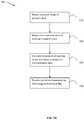
- FIG. 10shows a flowchart illustrating an example method 1000 for providing information for selection of an artificial bone flap.
- artificial bone flapit should be understood that this term is intended to encompass various implants designed to close a bone opening, including bone covers, bone meshes, and other such implants that may be referred to using other terms.
- the implantmay be made of any suitable biocompatible material, and may be fabricated using any suitable method including conventional casting and machining methods or using additive technologies such as 3D printing, for example. In some examples, fabrication of the implant may be performed just prior to the surgical procedure.
- the method 1000may take place as part of the planning method 800 , for example prior to exporting the plan to a navigation system.
- the method 1000may take place after the ROI(s), entry point, target point and sulcal path(s) have all been defined.
- the method 1000may take place prior to the user providing final confirmation of the surgical plan.
- the method 1000may take place elsewhere in the sequence of planning steps.
- the example method 1000in some cases when provided with the method 800 , may provide sufficient information for the planning and execution of the surgical procedure.
- the example method 1000may provide sufficient design information for just-in-time fabrication of an appropriate surgical implant.
- a user interfaceis provided for planning a neurosurgical procedure.
- This user interfacemay be provided by the planning system as part of the planning method 800 .
- these featuresmay be displayed as indicators or colored overlays in 2D and/or 3D views of the patient in the user interface.
- the entry pointmay have been defined as an opening in the patient's skull, with a defined boundary of the bone opening.
- the boundary of the bone openingmay be automatically defined as part of the planning described above (e.g., automatically calculated based on the location of the target and entry point, and/or the expected size of the access port) and/or may be manually set or adjusted by the user.
- the planning softwaremay receive user input that defines the boundary of the planned bone opening.
- the boundary of the bone openingmay be defined using a set of manually inputted points or a manually inputted trace in the 3D image.
- FIG. 9shows a circular indicator 910 for the bone opening
- the bone openingmay have other geometries and may be irregular in shape, which would be reflected in the geometry of the indicator 910 .
- a neurosurgical procedurethat includes closure of the bone opening
- This identification of one or more recommended partsmay be performed automatically by the planning system using a suitable software algorithm, which may use features such as surface area and/or curvature of the skull opening to search through and identify suitable candidate(s) from a library or database of existing pre-fabricated or pre-designed parts.
- a library or databasemay be provided by a parts ordering site or parts fulfillment system, which may be external to the planning system.
- the search through the databasemay be carried out using any suitable feature-based search algorithm, such as those used in the pattern recognition field, including a nearest neighbor algorithm or a maximum likelihood algorithm.
- the planning systemmay be further useful for the planning system to help identify suitable available (e.g., off-the-shelf) bone fasteners (e.g., bone screw, bone staple and/or bone adhesive, among others) for fastening the artificial bone flap, as well as suitable locations for placing the bone fasteners.
- suitable availablee.g., off-the-shelf
- bone fastenerse.g., bone screw, bone staple and/or bone adhesive, among others
- Pre-operative image dataincluding pre-operative 3D imaging data (e.g., CT and/or MRI data) may be used to determine the 3D dimensions of the planned bone opening.
- the 3D dimensions of the openingmay be determined by determining the dimensions (e.g., thickness, curvature and diameter) of the patient's skull within the defined boundary of the bone opening.
- bone density and/or bone structural integritymay be calculated for bone in the vicinity of the planned bone opening.
- the bone density and/or bone structural integritymay be calculated using pre-operative 3D imaging data.
- CT and/or MRI image datamay provide information about the thickness and density of the patient's skull in the vicinity of the planned bone opening.
- Such informationmay be obtained from image data using a suitable estimation method, such as those found in the medical imaging field. Examples of such methodology is provided in, for example, “Estimation of mechanical properties of cortical bone by computed tomography,” Susan M Snyder and Erich Schneider, Journal of Orthopedic Research, Vol 9, Issue 3, May 1991.
- Other informationmay be used to calculate the bone density and/or bone structural integrity as may be done in the medical imaging field. Examples of such other factors are described in, for example, “Environmental and genetic factors affecting bone mass similarity of bone density among members of healthy families,” Pierre Jouanny et. Al., Vol 38, Issue 1, January 1995, Arthritis & Rheumatism.
- Such calculations using pre-operative image datamay involve extensive modeling, calculations, finite element analysis etc. These calculations may involve modeling of the bone structure as composed of many interconnected structures that are small enough to apply a linear model for their respective mechanical properties.
- Calculation of the bone density and/or bone structural integrity in the vicinity of the bone openingmay be used to determine which bone fasteners would be appropriate and where the bone fasteners should be placed, as discussed further below. For example, if the bone in the vicinity of the bone opening is found to be thin or low density, the planning software may determine that a bone adhesive is more appropriate than a bone screw for fastening the artificial bone flap. Further, the planning software may determine that it is more appropriate to locate the bone fasteners (e.g., bone adhesives) farther away from the bone opening to avoid weakening the bone in the vicinity of the bone opening.
- the bone fastenerse.g., bone adhesives
- one or more locations suitable for attaching one or more bone flap fastenersmay be determined. This determination may be carried out based on the bone density and/or bone structural integrity calculated at 1010 .
- the planning softwaremay have a stored set of rules or guidelines that guide bone fastener location determination. For example, there may be a rule that the bone fastener must be located at least 1 cm away from the boundary of the bone opening. There may be another rule that the bone fastener must be located where the bone thickness or bone density is greater than a defined threshold. Such rules and guidelines may be preset in the planning software (e.g., as a hospital policy or preset by the surgeon).
- one or more suitable areas for attachment of bone fastener(s)may be presented visually as a pseudo-color map on a 3D surface image of the patient's skull. This may aid the user in visualizing suitable location(s) for bone fastener(s) and may help the user to understand alternatives for decision making during the surgical procedure.
- output indicating the recommended location(s) for attaching bone fastener(s)may be provided.
- the user interface 900may display bone fastener location indicator(s) 915 overlaid on the 2D and/or 3D views 905 a , 905 b , 905 c , 905 d .
- These location indicator(s) 915may be manually adjustable by the user, for example using point-and-click tools provided by the toolbar 907 .
- the usermay be provided with feedback such as a warning dialog.
- the parameter(s)may include, for example, the 3D dimensions of the bone opening, which may guide the recommended dimensions for the artificial bone flap (e.g., must have a diameter greater than that of the bone opening and/or must have a curvature similar to that of the bone opening) and/or suitable material(s) for the artificial bone flap (e.g., must be made of material(s) having a minimum amount of flexibility).
- the parameter(s)may include requiring the artificial bone flap to be large enough to be secured at the recommended bone fastener location(s).
- the artificial bone flapmay also be the basis for parameter(s) for selecting the artificial bone flap (e.g., the artificial bone flap should have a density similar to the bone density in the vicinity of the planned bone opening).
- Other parameters that may be used for selecting the artificial bone flapmay include bone thickness in the vicinity of the bone opening, or a patient characteristic (e.g., patient age or patient sex), among others.
- One or more recommended artificial bone flapsmay then be identified based on the parameter(s).
- the recommended artificial bone flap(s)may be identified from a database (e.g., stored locally at the planning system or accessed remotely from an ordering site or fulfillment system) of all available artificial bone flaps (e.g., a database of the inventory available in a hospital). For example, only the artificial bone flaps that match the recommended dimensions (e.g., within a range of +/ ⁇ 1 cm) may be recommended.
- one or more recommended bone fastenersmay also be identified by the planning system.
- the bone fastener(s)may be identified based on compatibility with the recommended artificial bone flap(s).
- recommended bone fastener(s)may be identified after the user has selected an artificial bone flap.
- identification of recommended bone fastener(s)may also be based on determination of what is suitable given the bone density and/or bone structural integrity in the vicinity of the planned bone opening.
- output indicating the recommended artificial bone flap(s)may be provided to the user.
- a list of recommended artificial bone flap(s), including model numbermay be presented in a list 920 on the user interface 900 .
- FIG. 9shows the list 920 as a drop-down list, in some examples the list 920 may be displayed to the side of the views 905 a , 905 b , 905 c , 905 d so as to avoid obscuring any images.
- the entries in the list 920may include the recommended artificial bone flap(s) as well as recommended bone flap fastener(s).
- the usermay select one or more entries from the list 920 to be included in the final surgical plan. Alternatively, the user may simply accept all recommended entries.
- the method 1000may omit steps 1010 and/or 1015 , in which case the method 1000 may also omit step 1020 and may not provide output indicating recommended bone fasteners and/or locations for attaching the bone fasteners.
- the method 1000may recommend, in addition to an artificial bone flap that best matches the 3D dimensions of the bone opening, additional artificial bone flaps that are larger and smaller (e.g., +/ ⁇ 10% in dimension) than the best match. This may be useful in case the actual intra-operative bone opening is larger or smaller than planned.
- the method 1000may further provide output to guide modification of a selected artificial bone flap.
- a surgeonmay manually manipulate a bone mesh to shape the mesh to conform to the curvature of a patient's skull.
- the method 1000may reduce or eliminate the repeated trial-and-error manipulation of the mesh.
- the planning softwaremay obtain the 3D dimensions of the selected artificial bone flap (e.g., obtaining the known dimensions from a database) and compare these 3D dimensions to the 3D dimensions of the bone opening. The difference between the 3D dimensions of the selected artificial bone flap and the 3D dimensions of the bone opening may be used to provide guidance for modifying the artificial bone flap.
- the usermay be provided with output (e.g., in the form of text and/or graphical display on the user interface 900 ) to manually shape the artificial bone flap to more closely match the curvature of the bone opening.
- outpute.g., in the form of text and/or graphical display on the user interface 900
- the guidance for manually shaping the artificial bone flapmay be based on intra-operative image data, as discussed below.
- the selection(s)may be outputted from the planning system to a part ordering site or fulfillment system (which may be external to the planning system) to order the part(s).
- the usermay choose instead to have a custom-made artificial bone flap fabricated based on the determined 3D dimensions of the bone opening.
- the 3D dimensions of the bone openingmay be exported (e.g., as a digital model) to a 3D fabrication system (which may be part of a bone flap ordering system), as discussed further below.
- the method 1000may be adapted for closing of an already existing bone opening. This may be done by calculating the 3D dimensions of the existing bone opening using a comparison of 3D image data before and after creation of the bone opening, or by extrapolating the curvature of the skull over the bone opening, for example. An example of such extrapolation is described with respect to FIG. 7B at 778 below.
- FIGS. 7A and 7Billustrate intra-operative steps, it should be understood that certain aspects, such as determining 3D dimensions of an existing bone opening (e.g., at 758 , 768 and 778 ), calculating dimensions for fabricating the artificial bone flap, and fabrication of an artificial bone flap (e.g., at 740 ), may be implemented pre-operatively as well.
- the finalized surgical planwhich may include a selection of artificial bone flap(s) and/or bone fastener(s), may be exported for use during the surgical procedure.
- FIG. 1illustrates a perspective view of an example minimally invasive port-based surgical procedure.
- a surgeon 101may conduct a minimally invasive port-based surgery on a patient 102 in an operating room (OR) environment.
- a craniotomymay be performed as part of the minimally invasive surgery, to provide access to the patient's brain.
- a localization or navigation system 200(described further below) may be used to assist the surgeon 101 during the procedure.
- an operator 103may be present to operate, control and provide assistance with the navigation system 200 .
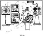
- FIG. 2Ashows a diagram illustrating components of an example medical navigation system 200 .
- the disclosed methods and systems for determining dimensions for fabrication of an artificial bone flapmay be implemented in the context of the medical navigation system 200 .
- the medical navigation system 200may include one or more displays 205 , 211 for displaying a video image, an equipment tower 201 , and a mechanical arm 202 , which may support an optical scope 204 (which may also be referred to as an external scope).
- One or more of the displays 205 , 211may include a touch-sensitive display for receiving touch input.
- the equipment tower 201may be mounted on a frame (e.g., a rack or cart) and may contain a power supply and a computer or controller that may execute planning software, navigation software and/or other software to manage the mechanical arm 202 and tracked instruments.
- the equipment tower 201may be a single tower configuration operating with dual displays 211 , 205 , however other configurations may also exist (e.g., dual tower, single display, etc.).
- the equipment tower 201may also be configured with a universal power supply (UPS) to provide for emergency power, in addition to a regular AC adapter power supply.
- UPSuniversal power supply
- a portion of the patient's anatomymay be held in place by a holder.
- the patient's head and brainmay be held in place by a head holder 217 .
- An access port 206 and associated introducer 210may be inserted into the head, to provide access to a surgical site in the head.
- the optical scope 204may be attached to the mechanical arm 202 , and may be used to view down the access port 206 at a sufficient magnification to allow for enhanced visibility down the access port 206 .
- the output of the optical scope 204may be received by one or more computers or controllers to generate a view that may be depicted on a visual display (e.g., one or more displays 205 , 211 ).
- the navigation system 200may include a tracked pointer 220 .
- the tracked pointer 220which may include markers 212 to enable tracking by the tracking camera 213 , may be used to identify points (e.g., fiducial points or points bordering a craniotomy opening, as discussed below) on a patient.
- FIG. 2Bshows an example use of a tracked pointer 220 to identify points on a patient.
- an operatortypically a nurse or the surgeon 101
- a guided robotic system with closed loop controlmay be used as a proxy for human interaction.
- Guidance to the robotic systemmay be provided by any combination of input sources such as image analysis, tracking of objects in the operating room using markers placed on various objects of interest, or any other suitable robotic system guidance techniques.
- Fiducial markers 212may be connected to the introducer 210 for tracking by the tracking camera 213 , which may provide positional information of the introducer 210 from the navigation system 200 .
- the fiducial markers 212may be alternatively or additionally attached to access port 206 .
- the tracking camera 213may be a 3D infrared optical tracking stereo camera similar to one made by Northern Digital Imaging (NDI).
- the tracking system 213may be an electromagnetic system (not shown), such as a field transmitter that may use one or more receiver coils located on the tool(s) to be tracked.
- Known profile of the electromagnetic field and known position of receiver coil(s) relative to each othermay be used to infer the location of the tracked tool(s) using the induced signals and their phases in each of the receiver coils. Operation and examples of this technology is further explained in Chapter 2 of “Image-Guided Interventions Technology and Application,” Peters, T.; Cleary, K., 2008, ISBN: 978-0-387-72856-7, incorporated herein by reference.
- Location data of the mechanical arm 202 and/or access port 206may be determined by the tracking camera 213 by detection of the fiducial markers 212 placed on or otherwise in fixed relation (e.g., in rigid connection) to any of the mechanical arm 202 , the access port 206 , the introducer 210 , the tracked pointer 220 and/or other pointing tools.
- the fiducial marker(s) 212may be active or passive markers.
- the secondary display 205may provide output of the computed data of the navigation system 200 . In some examples, the output provided by the secondary display 205 may include axial, sagittal and coronal views of patient anatomy as part of a multi-view output.
- the active or passive fiducial markers 212may be placed on tools (e.g., the access port 206 and/or the optical scope 204 ) to be tracked, to determine the location and orientation of these tools using the tracking camera and navigation system.
- the markers 212may be captured by a stereo camera of the tracking system to give identifiable points for tracking the tools.
- a tracked toolmay be defined by a grouping of markers 212 , which may define a rigid body to the tracking system. This may in turn be used to determine the position and/or orientation in 3D of a tracked tool in a virtual space.
- the position and orientation of the tracked tool in 3Dmay be tracked in six degrees of freedom (e.g., x, y, z coordinates and pitch, yaw, roll rotations), in five degrees of freedom (e.g., x, y, z, coordinate and two degrees of free rotation), but preferably tracked in at least three degrees of freedom (e.g., tracking the position of the tip of a tool in at least x, y, z coordinates).
- at least three markers 212are provided on a tracked tool to define the tool in virtual space, however it is known to be advantageous for four or more markers 212 to be used.
- Camera images capturing the markers 212may be logged and tracked, by, for example, a closed circuit television (CCTV) camera.
- the markers 212may be selected to enable or assist in segmentation in the captured images.
- IRinfrared
- An example of such an apparatusmay be tracking devices such as the Polaris® system available from Northern Digital Inc.
- the spatial position of the tracked tool and/or the actual and desired position of the mechanical arm 202may be determined by optical detection using a camera. The optical detection may be done using an optical camera, rendering the markers 212 optically visible.
- the markers 212may be used in combination with a suitable tracking system, to determine the spatial positioning position of the tracked tools within the operating theatre.
- Different tools and/or targetsmay be provided with respect to sets of markers 212 in different configurations. Differentiation of the different tools and/or targets and their corresponding virtual volumes may be possible based on the specification configuration and/or orientation of the different sets of markers 212 relative to one another, enabling each such tool and/or target to have a distinct individual identity within the navigation system 200 .
- the individual identifiersmay provide information to the system, such as information relating to the size and/or shape of the tool within the system.
- the identifiermay also provide additional information such as the tool's central point or the tool's central axis, among other information.
- the virtual toolmay also be determinable from a database of tools stored in or provided to the navigation system 200 .
- the markers 212may be tracked relative to a reference point or reference object in the operating room, such as the patient 102 .
- markersmay be used.
- the markers 212may all be the same type or may include a combination of two or more different types. Possible types of markers that could be used may include reflective markers, radiofrequency (RF) markers, electromagnetic (EM) markers, pulsed or un-pulsed light-emitting diode (LED) markers, glass markers, reflective adhesives, or reflective unique structures or patterns, among others.
- RF and EM markersmay have specific signatures for the specific tools they may be attached to. Reflective adhesives, structures and patterns, glass markers, and LED markers may be detectable using optical detectors, while RF and EM markers may be detectable using antennas. Different marker types may be selected to suit different operating conditions. For example, using EM and RF markers may enable tracking of tools without requiring a line-of-sight from a tracking camera to the markers 212 , and using an optical tracking system may avoid additional noise from electrical emission and detection systems.
- the markers 212may include printed or 3D designs that may be used for detection by an auxiliary camera, such as a wide-field camera (not shown) and/or the optical scope 204 .
- Printed markersmay also be used as a calibration pattern, for example to provide distance information (e.g., 3D distance information) to an optical detector.
- Printed identification markersmay include designs such as concentric circles with different ring spacing and/or different types of bar codes, among other designs.
- the contours of known objectse.g., the side of the access port 206
- the navigation system 200may include a portable three-dimensional (3D) scanner 222 .
- the 3D scanner 222may be used to obtain a 3D image of a portion of the patient's anatomy, for example an opening in the skull, as described further below.
- the image obtained by the 3D scanner 222may be registered in the virtual space of the navigation system 200 , for example by identifying and registering fiducial markers 212 captured in the 3D image.
- Minimally invasive brain surgery using an access port 206is a method of performing surgery on brain tumors.
- the introducer 210having an atraumatic tip, may be positioned within the access port 206 and employed to position the access port 206 within the patient's brain.
- the introducer 210may include fiducial markers 212 for tracking position and orientation of the introducer 210 .
- the fiducial markers 212may be passive (e.g., reflective spheres for use with an optical tracking system, or pick-up coils for use with an electromagnetic tracking system).
- the fiducial markers 212may be detected by the tracking camera 213 and the respective positions of the tracked tool may be inferred by tracking software executed by a computer or controller in connection with the navigation system 200 .
- the associated introducer 210may be removed to allow for access to the surgical site of interest, through the central opening of the access port 206 .
- Tracking of the access port 206may be provided by an access port guide or by attaching markers to the access port 206 itself.
- a guide clamp 218(or more generally a guide) for holding the access port 206 may be provided.
- the guide clamp 218may allow the access port 206 to be held at a fixed position and orientation while freeing up the surgeon's hands.
- An articulated arm 219may be provided to hold the guide clamp 218 .
- the articulated arm 219may have up to six degrees of freedom to position the guide clamp 218 .
- the articulated arm 219may be lockable to fix its position and orientation, once a desired position is achieved.
- the articulated arm 219may be attached or attachable to a point based on the patient head holder 217 , or another suitable point (e.g., on another patient support, such as on the surgical bed), to ensure that when locked in place, the guide clamp 218 does not move relative to the patient's head.
- setup of a navigation systemmay be relatively complicated; there may be many pieces of equipment associated with the surgical procedure, as well as elements of the navigation system 200 . Further, setup time typically increases as more equipment is added.
- the navigation system 200may include two additional wide-field cameras to enable video overlay information.
- One wide-field cameramay be mounted on the optical scope 204
- a second wide-field cameramay be mounted on the tracking camera 213 .
- Video overlay informationcan then be inserted into displayed images, such as images displayed on one or more of the displays 205 , 211 .
- the overlay informationmay illustrate the physical space where accuracy of the 3D tracking system (which is typically part of the navigation system) is greater, may illustrate the available range of motion of the mechanical arm 202 and/or the optical scope 204 , and/or may help to guide head and/or patient positioning.
- the navigation system 200may provide tools to the neurosurgeon that may help to provide more relevant information to the surgeon, and may assist in improving performance and accuracy of port-based neurosurgical operations.
- the navigation system 200may also be suitable for one or more of: brain biopsy, functional/deep-brain stimulation, catheter/shunt placement (in the brain or elsewhere), open craniotomies, and/or endonasal/skull-based/ear-nose-throat (ENT) procedures, among others.
- ENTendonasal/skull-based/ear-nose-throat
- the same navigation system 200may be used for carrying out any or all of these procedures, with or without modification as appropriate.
- a brain biopsymay involve the insertion of a thin needle into a patient's brain for purposes of removing a sample of brain tissue. The brain tissue may be subsequently assessed by a pathologist to determine if it is cancerous, for example.
- Brain biopsy proceduresmay be conducted with or without a stereotactic frame. Both types of procedures may be performed using image-guidance.
- Frameless biopsiesin particular, may be conducted using the navigation system 200 .
- the tracking camera 213may be part of any suitable tracking system.
- the tracking camera 213(and any associated tracking system that uses the tracking camera 213 ) may be replaced with any suitable tracking system which may or may not use camera-based tracking techniques.
- a tracking system that does not use the tracking camera 213such as a radiofrequency tracking system, may be used with the navigation system 200 .
- FIG. 3Ais a flow chart illustrating an example method 300 of performing a port-based surgical procedure using a navigation system, such as the medical navigation system 200 described above.
- the port-based surgical planmay be imported.
- a detailed description of an example process to create and select a surgical planis outlined in PCT application no. PCT/CA2014/050272, titled “PLANNING, NAVIGATION AND SIMULATION SYSTEMS AND METHODS FOR MINIMALLY INVASIVE THERAPY”, previously incorporated herein by reference.
- An example surgical planmay include pre-operative 3D imaging data (e.g., magnetic resonance imaging (MRI), computer tomography (CT), positron emission tomography (PET) or ultrasound data).
- the planmay include overlaid data, such as additional received inputs (e.g., sulci entry points, target locations, surgical outcome criteria and/or additional 3D image data information).
- the planmay also include a display of one or more planned trajectory paths (e.g., based on calculated score for a projected surgical path).
- Other surgical plans and/or methodsmay additionally or alternatively be used as inputs into the navigation system.
- the patientmay be affixed into position (e.g., using a body holding mechanism, such as the head holder 217 ).
- the patient's head positionmay be also confirmed with the plan using appropriate navigation software (at 304 ), which in an example may be implemented by the computer or controller forming part of the equipment tower 201 .
- registration of the patientmay be initiated (at 306 ).
- registrationmay refer to the process of transforming different sets of data into one coordinate system.
- Datamay include multiple photographs, data from different sensors, times, depths, or viewpoints, for example.
- the process of registrationmay be used in the context of the present disclosure for medical imaging, in which images from different imaging modalities may be co-registered. Registration may be used in order to be able to compare and/or integrate the data obtained from these different modalities.
- Registration of the patient to a base reference framemay occur in various suitable ways.
- Example methods for registrationmay include:
- a surface acquisition toolsuch as the 3D scanner 222 (which may operate based on structured light), to extract a surface of the patient's face or forehead and matching the extracted surface to the 3D clinical image data (e.g., 3D MR or CT volume) that is acquired prior to or during the surgical procedure.
- the matching processmay also be known as registration or image fusion.
- the processmay involve, for example, aligning common features, such as anatomical structures, in images acquired using different modalities by transforming one image relative to the other.
- the resulting geometric transformationprovides a means of correlating points in clinical images to coordinate frame of the operating room.
- the navigation system 200can help a surgeon visualize the positions of physical surgical tools relative to clinical images, such as MR, CT and ultrasound.
- Non-limiting examplesinclude intensity-based methods that compare intensity patterns in images via correlation metrics, as well as feature-based methods that find correspondence between image features such as points, lines, and contours, among other possible methods.
- Image registration methodsmay also be classified according to the transformation models they use to relate the target image space to the reference image space. Another classification can be made between single-modality and multi-modality methods. Single-modality methods typically register images in the same modality acquired by the same scanner or sensor type, for example, a series of MR images may be co-registered, while multi-modality registration methods are used to register images acquired by different scanner or sensor types, for example in MRI and PET.
- multi-modality registration methodsmay be used in medical imaging of the head and/or brain as images of a patient are frequently obtained from different scanners. Examples include registration of brain CT/MRI images or PET/CT images for tumor localization, registration of contrast-enhanced CT images against non-contrast-enhanced CT images, and registration of ultrasound and CT.
- FIG. 3Bshows a flow chart illustrating example methods that may be used to carry out the registration of the block 306 .
- Block 340illustrates an approach using fiducial touch points
- block 350illustrates an approach using a surface scan.
- the block 350is not typically used when fiducial touch points or a fiducial pointer is used.
- the methodmay involve first identifying fiducial points on images (at 342 ), then touching the corresponding touch points on the patient with the tracked pointer 220 (at 344 ). Next, the navigation system may compute the registration to reference markers (at 346 ).
- the patient's heade.g., face, back of head and/or skull
- the 3D scanner 222may be scanned using the 3D scanner 222 (at 352 ).
- the corresponding surface of the patient's headmay be extracted from image data (e.g., MR or CT data) (at 354 ).
- the scanned surface and the extracted surfacemay be matched to each other to determine registration data points (at 356 ).
- the data extractedmay be computed and used to confirm registration at block 308 , shown in FIG. 3A .
- the patientmay be draped (at 310 ).
- drapinginvolves covering the patient and surrounding areas with a sterile barrier to create and maintain a sterile field during the surgical procedure. Draping may be used to eliminate the passage of microorganisms (e.g., bacteria) between non-sterile and sterile areas.
- microorganismse.g., bacteria
- the patient engagement pointsmay be confirmed (at 312 ) and then the craniotomy may be prepared and planned (at 314 ).
- the craniotomymay be cut and a bone flap may be removed from the skull to access the brain (at 316 ).
- cutting the craniotomymay be assisted by a visual indication of the location, size and/or shape of the planned craniotomy (e.g., a projection of a planned outline onto the patient's skull).
- Registration datamay be updated with the navigation system at this point (at 322 ).
- the engagement within craniotomy and the motion rangemay be confirmed (at 318 ).
- the proceduremay advance to cutting the dura at the engagement points and identifying the sulcus (at 320 ). Registration data may again be updated with the navigation system at this point (at 322 ).
- update of the registration datamay be adjusted to help achieve a better match for the region of interest, while ignoring any non-uniform tissue deformation, for example, affecting areas outside of the region of interest.
- the particular tissue representationmay be matched to the live video image, which may help to improve registration of the tissue of interest.
- the registrationmay enable: matching a live video of the post craniotomy brain (with the brain exposed) with an imaged sulcal map; matching the position of exposed vessels in a live video with image segmentation of vessels; matching the position of lesion or tumor in a live video with image segmentation of the lesion and/or tumor; and/or matching a video image from endoscopy up the nasal cavity with bone rendering of bone surface on nasal cavity for endonasal alignment.
- multiple camerascan be used and overlaid with tracked instrument(s) views, which may allow multiple views of the image data and overlays to be presented at the same time. This may help to provide greater confidence in registration, or may enable easier detection of registration errors and their subsequent correction.
- Cannulationtypically involves inserting an access port into the brain, typically along a sulcus path as identified at 320 , along a trajectory plan.
- Cannulationis typically an iterative process that may involve repeating the steps of aligning the port on engagement and setting the planned trajectory (at 332 ) and then cannulating to the target depth (at 334 ) until the complete trajectory plan is executed (at 324 ).
- the cannulation processmay also support multi-point trajectories where a target (e.g., a tumor) may be accessed by cannulating to intermediate points, then adjusting the cannulation angle to get to the next point in a planned trajectory.
- a targete.g., a tumor
- This multi-point trajectorymay be contrasted with straight-line trajectories where the target may be accessed by cannulating along a straight path directly towards the target.
- the multi-point trajectorymay allow a cannulation trajectory to skirt around tissue that the surgeon may want to preserve.
- Navigating multi-point trajectoriesmay be accomplished by physically reorienting (e.g., adjusting the angle of) a straight access port at different points along a planned path, or by using a flexible port, such as an access port with manipulatable bends that may be bent along the multi-point trajectory.
- the skull opening created by the craniotomy at 316may be widened by cutting out more bone during the cannulation process. Widening of the skull opening may be needed to achieve the desired cannulation angle, for example, where the original craniotomy was found to be insufficient.
- the surgeonmay perform resection (at 326 ) to remove part of the brain and/or tumor of interest, with or without having first removed the introducer (if used). The surgeon may then decannulate (at 328 ) by removing the port from the brain. Finally, the surgeon may close the dura and complete the craniotomy (at 330 ). Closure of the craniotomy may involve replacement of the bone flap removed at 316 , or may involve closure using an artificial bone flap, which may be fabricated intra-operatively as described further below.
- FIGS. 3A and 3Bmay be specific to port-based surgery, such as portions of blocks 328 , 320 , and 334 . Appropriate portions of these blocks may be skipped or suitably modified when performing non-port-based surgery.
- FIG. 4shows an example of how, during use, the navigation system 200 may be operated to determine a coordinate frame 440 , which contains the actual spatial locations of tracked elements (e.g., the mechanical arm 202 , the access port 206 , the introducer 210 , the tracked pointer 220 and/or other pointing tools) in the operating room and their spatial relations to one another.
- tracked elementse.g., the mechanical arm 202 , the access port 206 , the introducer 210 , the tracked pointer 220 and/or other pointing tools
- Another example of such tracked elementsmay be a surgical real-time imaging camera such as the optical scope 204 . This may be a moveable camera used for visualization of the surgical area of interest, a surgical volume of interest such as a brain, and/or medical instruments.
- a 3D virtual volume representing pre-operative image data of patient anatomymay be provided to the navigation system 200 , and may be displayed on one or more displays 205 , 211 .
- the virtual volumemay be acquired using a patient with attached fiducial markers (not shown). The fiducial markers may remain attached in place on the patient (or else their locations may have been marked on the patient) in a manner which persists through the registration step in order to register the pre-operative imaging data with the patient in the operating room.
- actual fiducial markers positioned on the patient's headmay be virtually in the same position relative to the patient's virtual brain scan as the actual fiducial markers relative to the patient's actual brain.
- the spatial correspondence between the actual fiducial markers and the virtual fiducial markerspermits the actual and virtual coordinate frames to be aligned, which allows for an accurate overlay of virtual image data onto the actual image data.
- This overlay of imagesmay be achieved by combining video from a virtual camera 410 depicting the virtual operating room (OR) surgical field and video from an actual surgical imaging camera 420 depicting the actual OR surgical field.
- the two cameras 410 , 420should be coincidentally aligned and have substantially the same optical properties.
- the alignment of the virtual camera 410 in a virtual coordinate frame 430(defined in the navigation system 200 ) may be constrained to be equivalent to the alignment of the actual camera 420 , relative to the actual coordinate frame 440 of the operating room, and have the same optical properties as the actual camera 420 , namely, the same field-of-view, aspect ratio, and optical distance. This may be accomplished using the navigation system 200 .
- the tracked pointer 220 controlled by a user 450may be used to confirm the spatial location of the actual fiducial markers in virtual space as depicted in a picture frame 480 shown in the upper right hand side in FIG. 4 .
- the virtual and actual coordinate frames 430 , 440become more accurately aligned.
- the tip of the tracked pointer 220indicates the spatial position of a fiducial marker in actual space (in this example, located above the left eyebrow of the patient)
- its virtual counterpart fiducial markeraligns with it resulting in the navigation system virtual coordinate frame 430 to transform 460 and align its origin with the operating room actual coordinate frame 440 .
- Thisalso results in the two cameras 410 , 420 realigning themselves accordingly.
- the relative shift in alignment of the cameras 410 , 420may be proportional to the shift between the virtual alignment of the overlay on the actual image data between diagrams 490 and 400 .
- the coordinate frames 430 , 440may be still rotationally misaligned, as illustrated in the example bottom left picture frame 400 in FIG. 4 . Accordingly, the alignment process may be repeated and another point is registered. In this example iteration the fiducial marker being aligned is located near the right ear of the patient and this causes a rotation of the virtual coordinate frame 430 , resulting in it and the actual coordinate frame 440 to better coincidently align.
- FIG. 5shows a block diagram of an example system configuration that may be used to carry out the functions of a planning system and/or a navigation system (with modifications as appropriate), as disclosed herein.
- the example systemmay include a control and processing unit 500 and other external components.
- the same control and processing unit 500may be used for both planning and navigation.
- different instances of the control and processing unit 500may be used for planning and navigation.
- control and processing unit 500may include one or more processors 502 (for example, a CPU and/or microprocessor), one or more memories 504 (which may include random access memory (RAM) and/or read-only memory (ROM)), a system bus 506 , one or more input/output interfaces 508 (such as a user interface for a user (e.g., a surgeon) to provide various inputs (e.g., to perform trajectory planning or run simulations)), one or more communications interfaces 510 , and one or more internal storage devices 512 (e.g. a hard disk drive, compact disk drive and/or internal flash memory).
- the control and processing unitmay also include a power supply (not shown).
- the control and processing unit 500may interface with one or more other external devices, such as a tracking system or navigation system (e.g., the navigation system 200 of FIG. 2 ), a data storage device 542 , and external input and/or output devices 544 which may include, for example, one or more of a display, keyboard, mouse, foot pedal, microphone and speaker.
- the data storage device 542may include any one or more suitable data storage devices, such as a local or remote computing device (e.g., a computer, a hard drive, a digital media device, or a server) which may have a database stored thereon.
- the data storage device 542may store identification data 550 for identifying one or more medical instruments 560 and configuration data 552 that may associate customized configuration parameters with the one or more medical instruments 560 .
- the data storage device 542may also store preoperative image data 554 and/or medical procedure planning data 556 .
- the data storage device 542is shown as a single device, the data storage device 542 may be provided as one or more storage devices.
- the medical instrument(s) 560may be identifiable by the control and processing unit 500 .
- the medical instrument(s) 560may be connected to, and controlled by, the control and processing unit 500 , or may be operated or otherwise employed independently of the control and processing unit 500 .
- the navigation system 200may be employed to track one or more of the medical instrument(s) 560 and spatially register the one or more tracked medical instruments 560 to an intra-operative reference frame, for example as discussed above.
- the control and processing unit 500may also interface with one or more other configurable devices 520 , and may intra-operatively reconfigure one or more of such device(s) 520 based on configuration parameters obtained from configuration data 552 , for example.
- Examples of the device(s) 520may include one or more external imaging devices 522 , one or more illumination devices 524 , the mechanical arm 202 , one or more projection devices 528 , and one or more displays 205 , 211 .
- processing engines 570include, but are not limited to, a user interface engine 572 , a tracking engine 574 , a motor controller 576 , an image processing engine 578 , an image registration engine 580 , a procedure planning engine 582 , a navigation engine 584 , and a context analysis engine 586 .
- a user interface engine 572a tracking engine 574 , a motor controller 576 , an image processing engine 578 , an image registration engine 580 , a procedure planning engine 582 , a navigation engine 584 , and a context analysis engine 586 .
- the systemis not intended to be limited to the components shown in FIG. 5 .
- one or more components of the control and processing unit 500may be provided as an external component or device. Although only one of each component is illustrated in FIG. 5 , any number of each component can be included.
- a computertypically contains a number of different data storage media.
- the bus 506is depicted as a single connection between all of the components, the bus 506 may represent one or more circuits, devices or communication channels which link two or more of the components.
- the bus 506may include or may be a motherboard.
- the navigation engine 584may be provided as an external navigation system that may interface with or be integrated with the control and processing unit 500 .
- control and processing unit 500may be, or may include, a general purpose computer or any other hardware equivalents configured for operation in space.
- the control and processing unit 500may also be implemented as one or more physical devices that may be coupled to the processor(s) 502 through one or more communications channels or interfaces.
- the control and processing unit 500may be implemented using application specific integrated circuits (ASIC).
- ASICapplication specific integrated circuits
- control and processing unit 500may be implemented as a combination of hardware and software, such as where the software may be loaded into the processor(s) 502 from the memory(ies) 504 or internal storage(s) 512 , or from an external source (e.g., via the communication interface(s) 510 , such as over a network connection).
- the present disclosureis not limited to a specific configuration of hardware and/or software.
- FIG. 6illustrates the tissues that may be encountered during the port-based surgery.
- the tissuesmay include a skull 600 , a dural layer 610 (or dura), a cerebrospinal fluid (CSF) layer 620 , blood vessels 630 , and a brain section including grey matter 640 , white matter 650 , diffusion or brain fibers 660 , and a tumor target 670 .
- CSFcerebrospinal fluid
- FIG. 7Ais a flow chart outlining an example method 700 for fabricating an artificial bone flap.
- FIG. 7Bshows further details of the method 700 .
- the method 700may be carried out within the context of the navigation system 200 , as described above. Although the surgeon 101 is described as being the principle operator in the method 700 , a nurse or other operator 103 may alternatively or additionally be involved in carrying out the method.
- a reference image of at least a portion of the patient's skullmay be obtained.
- the reference imagemay be a pre-operative image or may be obtained during the procedure (but prior to performing the craniotomy).
- the reference imageis typically a 3D image, which may be obtained using a MR or CT imaging system, or the 3D scanner 222 .
- the reference imagemay be obtained using suitable techniques to image the patient's bone. For example, an appropriate pulse sequence may be selected for MR image acquisition, in order to capture bone tissue. In some examples, ultrashort echo time (UTE) MRI methods may be used to image the patient's bone.
- the reference imageis a MR or CT image
- the reference imagemay be obtained pre-operatively, for example prior to the process illustrated in FIG.
- the reference imagemay additionally be used for planning the procedure.
- the reference imagemay be obtained after the patient has been prepped (e.g., after the patient's hair has been shaved in the required region or after the skull has been exposed) but before performing the craniotomy.
- the reference imagemay be used to capture the shape of the skull bone prior to craniotomy.
- the reference imagemay capture one or more fiducial markers positioned at relatively fixed positions on the patient's head or skull. Such fiducial markers may remain in place during the length of the procedure, to ensure proper registration of virtual and actual coordinate systems, as described above.
- fiducial markersmay be placed during on the patient's exposed skull in the vicinity of the planned craniotomy. Fiducial markers placed directly on the exposed skull may be captured by a 3D surface scan using the 3D scanner 222 . By placing fiducial markers directly on the exposed skull, unwanted shifting of the fiducial markers due to movement of the patient's skin may be avoided.
- the reference imagemay be used (at 710 or later in the method 700 ) to determine the curvature and thickness of the skull at the site of the craniotomy. Where such reference image is lacking in quality or missing, alternative methods, such as those described further below, may be used to infer curvature of the skull at or around the craniotomy location.
- the craniotomymay be performed, and at 720 intra-operative data of the craniotomy opening may be obtained.
- Obtaining the intra-operative datamay include obtaining 3D image data 750 , obtaining a set of points defining a boundary of the craniotomy 760 and/or obtaining 2D image data 770 .
- obtaining 3D image data of the craniotomymay include obtaining a 3D surface scan of the craniotomy, such as by using a portable 3D scanner 222 or using optical coherence tomography (OCT) imaging (e.g., using a remotely operated robotically guided OCT system).
- OCT imagingmay allow the imaging of surface structures and sub-surface structures up to a limited depth (e.g., around 3 mm), and at a relatively high resolution.
- a method for obtaining OCT surface imagesmay involve the use of steerable mirrors to scan a beam of light across the surface being imaged; however, the scanned area is often a maximum of 1 cm 2 , which is too small to cover the full area of a typical craniotomy.
- the surface area covered by the OCT scanmay be increased by systematically moving the scanning head of the OCT system (e.g., using a robotic system to ensure precise and systematic movement), obtaining individual scans at each position, and then combining the small scanned areas together to form a larger surface map.
- a surface scan obtained using OCT in this waywould also contain information about sub-surface structures up to the limited depth permitted by OCT.
- the 3D image datamay capture the positions of the fiducial markers on the patient, to enable the captured intra-operative data to be related to the reference image obtained at 710 .
- the 3D image datamay capture the size, shape and depth of the skull opening created by the craniotomy.
- data defining a boundary of the craniotomymay be obtained as a set of points along the boundary of the craniotomy.
- the boundarymay be defined by the surgeon 101 manually touching points or tracing along the border of the craniotomy directly on the patient's skull using a tracked pointer 220 .
- a series of points defining the border of the craniotomymay be obtained.
- the positional data of the tip of the tracked pointer 220may be automatically tracked and stored (e.g., at regular time intervals, such as every 500 ms) by the navigation system 200 .
- the surgeon 101may manually trigger the storage of positional data at each touched point.
- the tracked pointer 220may also be used to indicate the thickness of the skull (e.g., by collecting positional data at points on the outer and inner edges of the craniotomy) and/or may also be used to indicate the curvature of the exposed dura (e.g., by collecting positional data at points on various locations on the dura). In some examples, this data may be used to approximate the thickness and/or curvature of the artificial bone flap to be fabricated.
- the surgeon 101may provide input to the computer or control unit to indicate that the set of data is complete.
- the computer or control unitmay then verify the collected data for consistency and completeness (e.g., perform algorithms to verify that the boundary forms a closed loop, that the boundary falls within the planned craniotomy and/or that the boundary does not deviate significantly from the planned craniotomy) and may cause the defined boundary to be displayed (e.g., overlaid on a 2D image on the display 205 , 211 ) for confirmation by the surgeon 101 .
- such verification and/or feedbackmay be provided to the surgeon 101 during the obtaining of the set of points, to inform the surgeon 101 whether more points are needed or whether a sufficient number of points has been obtained.
- obtaining 2D image data of the craniotomymay include obtaining a 2D optical image or video of the craniotomy, such as using the optical scope 204 .
- the 2D image datamay capture the position of the fiducial markers on the patient, to enable the captured intra-operative data to be related to the reference image obtained at 710 .
- a boundary of the craniotomymay be determined in the 2D image.
- the boundarymay be determined by manually defining the boundary in a captured 2D image.
- the 2D imagemay be displayed on the display 205 , 211 and the surgeon 101 may use mouse input or touchscreen input, for example, to draw or trace the boundary of the craniotomy as shown in the 2D image.
- the computer or control unitmay perform an automatic edge detection algorithm to determine the boundary of the craniotomy as displayed in the 2D image.
- the surgeon 101may provide input to the computer or control unit to indicate that the input is complete.
- the computer or control unitmay then verify the data for consistency and completeness (e.g., verify that the boundary forms a closed loop, that the boundary falls within the planned craniotomy and/or that the boundary does not deviate significantly from the planned craniotomy) and may display the defined boundary (e.g., overlaid on the 2D image on the display 205 , 211 ) for confirmation by the surgeon 101 .
- obtaining intra-operative data of the opening at 720may include verification that the measured opening matches the planned craniotomy (e.g., as planned at 314 in FIG. 3A ). If the intra-operative data indicates a location, size and/or shape of the craniotomy that deviates from the planned craniotomy by more than a predetermined amount (e.g., a difference of more than 1 cm) a warning or notification may be generated (e.g., as a visual display on the display 205 , 211 ) indicating that the intra-operative data may be inaccurate or that the craniotomy may differ significantly from the plan.
- a predetermined amounte.g., a difference of more than 1 cm
- the dimensions of the openingmay be calculated based on the reference image and the intra-operative data. Where the intra-operative data has not been registered with the reference image, a registration of the intra-operative data and the reference image may be carried out as part of block 730 . The intra-operative data may be compared against the reference image to determine the size, shape, thickness and/or curvature of the bone flap that was removed to create the opening.
- calculating the dimensions of the openingmay include registering the 3D image data to the reference image (at 756 ) and comparing the 3D image data to the reference image (at 758 ).
- registration of the 3D image data to the reference imagemay include identifying fiducial markers captured in each of the 3D image and the reference image and registering the fiducial markers of each image to each other, using suitable registration techniques.
- the registered 3D and reference imagesmay then be compared against each other to determine the portion of the skull (in the reference image) that was cut to form the opening (in the 3D image). For example, the 3D image may be subtracted from the reference image in order to obtain the portion of the skull that was cut to form the opening.
- calculating the dimensions of the openingmay include determining the boundary defined by the set of points (at 764 ), registering the boundary to the reference image (at 766 ) and determining the dimensions of the skull (in the reference image) that falls within the boundary (at 768 ).
- determining the boundary defined by the set of pointsmay be carried out using suitable algorithms for connecting the points to generate a relatively smooth, closed loop.
- Example mathematical algorithms for defining such boundaryinclude cubic spline routines and polynomial functions in 3D space.
- the surface of the skullmay be also incorporated using spline surfaces, which are smooth surfaces with defined curvature and boundary.
- the spline surfacemay be a mathematical model of the removed bone flap. This may be carried out using the computer or control unit in the navigation system. Determining the boundary may include quality assurance checks.
- the computer or control unitmay verify that there are a sufficient number of points to generate a smooth, closed loop, that the boundary falls within the planned craniotomy and/or that the boundary does not deviate significantly from the planned craniotomy.
- One or more of these quality assurance checksmay also be carried out while obtaining the set of points at 760 , and feedback may be provided to the surgeon 101 during the obtaining, to indicate whether more points are needed.
- the determined boundarymay be registered to the reference image by relating the location of the set of points to the reference image in the virtual coordinate system. Since the set of points may be obtained using the tracked pointer 222 , the location of each point may already be defined in the virtual coordinate system. Using the known virtual coordinates of fiducial markers in the reference image, the determined boundary may be registered to the reference image. In some examples, registration of the set of points to the reference image may take place before determining the boundary. Registering the set of points to the reference image before determining the boundary may be useful for performing quality assurance checks.
- the dimensions of the skull within the boundarymay be determined by determining the dimensions (including skull thickness and curvature, for example) of the reference image that is bounded by the registered boundary.
- calculating the dimensions of the openingmay include registering the 2D image data to the reference image (at 776 ) and determining the dimensions of the skull (in the reference image) that falls within the boundary (at 778 ).
- registering the 2D image data to the reference imagemay include identifying fiducial markers captured in each of the 2D image and the reference image and registering the fiducial markers of each image to each other, using suitable registration techniques. Once the 2D image is registered with the reference image, the boundary determined in the 2D image (at 772 ) may be automatically registered to the reference image.
- determining the dimensions of the skull within the boundarymay include determining the dimensions (including skull thickness and curvature, for example) of the reference image that is bounded by the registered boundary. Where such reference image is lacking in resolution or missing, it may be augmented by interpolating the intra-operative 3D scan of the intact portion of the skull or head to infer the curvature of the removed bone flap piece. This interpolation may be performed, for example, by creating a mathematical grid to represent the entire head using the intact portion of the head. Then, assuming that the head surface, and hence the skull surface, is relatively smooth, the surface grid may be interpolated over the bone flap region to arrive at a “filled in” model. The latter information may then be used to represent the curvature of the bone flap surface.
- the calculated dimensions for fabricating the artificial bone flapmay be provided. This may include providing data suitable for use by a fabrication system, for fabricating the artificial bone flap.
- the calculated dimensionsmay be transmitted to the fabrication system in the form of data signals (e.g., through wired or wireless communication) or may be provided in a tangible form (e.g., a storage medium such as a computer readable memory) to be manually transferred to the fabrication system.
- the computer or control unitmay carry out further processing of the dimensions before providing the dimensions to a fabrication system.
- the calculated dimensions of the openingmay be provided in the form of a digital 3D model of the artificial bone flap that is to be fabricated.
- the 3D modelmay be only for a portion of the removed bone flap, such as a remaining portion of the natural bone flap has been preserved. This may be useful where only a portion of the natural bone flap could be salvaged. This approach may help with bone regeneration and patient healing, as part of the living tissue is reused.
- the calculated dimensionsmay be used to facilitate selection and/or cutting of a segment of an artificial dura (e.g., made of a synthetic or biological material) which may be used to close the open dura in the patient.
- the calculated dimensionsmay help in selection of an artificial dura from a pre-existing inventory of differently-sized artificial duras.
- the cutting of a segment of the artificial dura(either cutting the artificial dura from a large piece of material or trimming of a pre-sized piece of material) may be guided by a boundary that is optically projected on to the cutting surface.
- the projected boundarymay be generated based on the calculated dimensions provided at 740 .
- Example techniques for projecting a boundary on the artificial durainclude a laser dot that is moved reasonably swiftly over the surface of the artificial dura to generate a cutting track or an image directly projected on the cutting surface using projected light from a fixed distance, for example.
- the computer or control unitmay, in addition to the calculated dimensions, provide scaled versions (e.g., 95% or 90%) of the calculated dimensions, in order to fabricate one or more artificial bone flaps that are slightly smaller than the actual calculated dimensions of the craniotomy. Fabricating the artificial bone flap to be slightly smaller than the calculated dimensions of the opening may be useful to provide a margin of error (e.g., to accommodate possible errors in determining the boundary of the craniotomy) when fitting the artificial bone flap into the opening.
- scaled versionse.g., 95% or 90%
- a slightly smaller artificial bone flapmay also provide a small gap between the perimeter of the artificial bone flap and the patient's skull, into which bonding substances and devices (e.g., bio-adhesives, sutures, plates and/or wires) may be introduced to aid in healing.
- bonding substances and devicese.g., bio-adhesives, sutures, plates and/or wires
- the calculated dimensionsmay be provided (e.g., as a digital model) as input to a fabrication system for additive or subtractive 3D manufacturing. Any suitable rapid prototyping system may be used to fabricate the artificial bone flap.
- Additive 3D manufacturingmay also be referred to as 3D printing and may include various suitable manufacturing techniques including extrusion deposition, binding of granular materials, laminated object manufacturing, or photopolymerization, among others.
- Subtractive 3D manufacturingmay include techniques such as etching, cutting or drilling, among others.
- the fabrication of the artificial bone flapmay be relatively fast (e.g., being complete in time for the artificial bone flap to be used to close the craniotomy at the end of the procedure), such as within less than 30 minutes. Where the fabrication technique is suitably fast, multiple artificial bone flaps may be manufactured while the procedure is still ongoing.
- the calculated dimensionsmay be also used to facilitate selection of an artificial bone flap from a pre-existing inventory of differently-sized artificial bone flaps.
- artificial bone flap replacement componentsmay be purchased in different predefined sizes.
- the calculated dimensionsmay aid in selecting the desired predefined size that meets the needs of a particular procedure. Further, after the artificial bone flap has been selected from predefined sizes, the calculated dimensions may be further used to trim or otherwise shape (e.g., by manually bending or shaping a bone mesh) the pre-sized artificial bone flap to meet the exact dimensional requirements for the procedure.
- the calculated dimensionsmay be used to guide modification (e.g., trimming and/or manually shaping) of the pre-selected artificial bone flap.
- the 3D dimensions of the pre-selected artificial bone flape.g., obtained by performing a 3D scan of the artificial bone flap or obtained by looking up the dimensions from a catalogue or database
- any differencesmay be the basis of guidance for modifying the pre-selected artificial bone flap to better conform to the 3D dimensions of the bone opening.
- the calculated dimensionsmay be used to guide selection of which one artificial bone flap should be used.
- the fabricated artificial bone flapmay be used to help shape (e.g., bend) other materials that will also be used to close the cranial opening.
- the artificial bone flapmay serve as a guide to help bend mesh-like cranial opening covers so that the mesh structures closely match the curvature that is present on the head surface in the vicinity of the cranial opening.
- the artificial bone flapmay be fabricated using any suitable biocompatible material.
- the artificial bone flapmay be fabricated to be relatively porous, to assist in bone growth and patient healing.
- suitable materialsinclude calcium phosphate, polyethylene, bioactive glass and demineralized bone. Other materials may be used. Details of the suitability of various materials are presented in “Reconstruction of Skull Defects: Currently Available Materials,” Goiato et. al., J Craniofac Surg 2009; 20: 1512-1518, which is hereby incorporated by reference.
- more than one artificial bone flapmay be fabricated.
- the plurality of artificial bone flapsmay be identical or may be different in material and/or dimensions.
- different artificial bone flapsmay be fabricated using different materials (e.g., selected among a variety of suitable biocompatible materials), which may be useful to enable the surgeon to select the artificial bone flap having a desired material property (e.g., stiffness) to suit the patient.
- Different artificial bone flapsmay also be fabricated with different dimensions. For example, several artificial bone flaps may be fabricated at 100%, 90% and 80% of the size of the calculated dimensions. By providing a variety of sizes, the surgeon may be able to select the artificial bone flap that accommodates a desired bonding method and/or best fits the actual craniotomy opening.
- the fit of a fabricated artificial bone flapmay be assessed by holding the artificial bone flap in the field of view of the camera system used at 770 .
- the image processing system used to estimate the profile and dimensions of the craniotomymay be used to estimate similar information for the artificial bone flap.
- the computed profile and dimensions of the artificial bone flapmay be then automatically compared to those of the craniotomy to confirm that the artificial bone flap will fit the craniotomy opening without having to actually place the fabricated bone flap on the opening.
- the artificial bone flapmay then be used to close the craniotomy, using suitable techniques, instead of the original bone flap removed to create the craniotomy.
- selection, modification and/or fabrication of an artificial bone flapmay be guided by feedback provided during pre-operative planning.
- a functionmay be integrated into a planning system, such as the system described in PCT application no. PCT/CA2014/050272, titled “PLANNING, NAVIGATION AND SIMULATION SYSTEMS AND METHODS FOR MINIMALLY INVASIVE THERAPY”, previously incorporated by reference. It should be understood that such guidance and feedback may be provided only pre-operatively, only intra-operatively, or throughout both pre-operative and intra-operative stages.
- the present disclosureenables automated feedback for selection of an artificial bone flap to be provided during planning of a surgical procedure. This may be useful to simplify the selection of artificial bone flaps and increase efficiency. Further, the automated feedback may take into consideration factors such as bone density and structural integrity in the vicinity of the bone opening, using calculations based on pre-operative image data. Such consideration may not be possible in conventional manual selection of artificial bone flaps.
- the present disclosureenables an artificial bone flap to be fabricated, for example while a neurosurgery is ongoing.
- the measurement, fabrication and completion of the artificial bone flapmay all take place during the procedure, and in near real-time, in parallel with the procedure.
- the artificial bone flapcan be customized to the specific craniotomy created and be available to close the craniotomy at the end of the procedure.
- Obtaining a reference image (e.g., a MR or CT image) of the patient's skullis typically already performed as part of pre-operative planning, and obtaining intra-operative data of the craniotomy opening may be relatively simple and quick (e.g., obtaining a 3D image using a portable 3D scanner).
- the present disclosuremay be implementable in standard neurosurgery with relatively little impact on the length and/or complexity of the procedure.
- the present disclosuremay be used to create an artificial bone flap to close a skull opening for a patient on whom a craniectomy was previously performed. This may be useful for cases where the original bone flap may be no longer available or where preserving the original bone flap for an extended period of time may be problematic.
- larger portions of the skullmay be artificially fabricated for the purpose of maxiofacial reconstruction.
- the present disclosuremay also be adapted to fabricate vertebral components or bodies for the purpose of reconstructive surgery of the spine.
- the present disclosuremay be implemented in addition to or as a backup for conventional procedures that use the patient's original bone flap to close the craniotomy.
- the artificial bone flapmay be selected or fabricated as a backup in case the original bone flap is or becomes unsuitable for closing the craniotomy (e.g., the original bone flap is or becomes damaged or contaminated).
- the present disclosureprovides examples in the context of cranial surgery, the disclosed systems and methods may be applied to any other suitable procedure where a portion of the bone or rigid anatomical structure needs to be removed during a surgical procedure and then replaced at the conclusion of the procedure. Examples of such procedures include maxiofacial procedures and spinal procedures where portion of the spinal structure may be removed for subsequent replacement with real or artificial bone structure.
- information about the bone flap (and optionally bone fasteners), whether selected from existing available bone flaps or manufactured on-the-fly,may be stored for future use. For example, dimensions and/or model numbers of the parts used may be uploaded to a database or an informatics system. This information may be used for training purposes, to assist in future planning, to be shared with other hospitals or surgeons, atlased, or otherwise archived for future reference.
- At least some aspects disclosedmay be embodied, at least in part, in software. That is, some disclosed techniques and methods may be carried out in a computer system or other data processing system in response to its processor, such as a microprocessor, executing sequences of instructions contained in a memory, such as ROM, volatile RAM, non-volatile memory, cache or a remote storage device.
- processorsuch as a microprocessor
- a memorysuch as ROM, volatile RAM, non-volatile memory, cache or a remote storage device.
- a computer readable storage mediummay be used to store software and data which when executed by a data processing system causes the system to perform various methods or techniques of the present disclosure.
- the executable software and datamay be stored in various places including for example ROM, volatile RAM, non-volatile memory and/or cache. Portions of this software and/or data may be stored in any one of these storage devices.
- Examples of computer-readable storage mediamay include, but are not limited to, recordable and non-recordable type media such as volatile and non-volatile memory devices, read only memory (ROM), random access memory (RAM), flash memory devices, floppy and other removable disks, magnetic disk storage media, optical storage media (e.g., compact discs (CDs), digital versatile disks (DVDs), etc.), among others.
- the instructionscan be embodied in digital and analog communication links for electrical, optical, acoustical or other forms of propagated signals, such as carrier waves, infrared signals, digital signals, and the like.
- the storage mediummay be the Internet cloud, or a computer readable storage medium such as a disc.
- the methods described hereinmay be capable of being distributed in a computer program product comprising a computer readable medium that bears computer usable instructions for execution by one or more processors, to perform aspects of the methods described.
- the mediummay be provided in various forms such as, but not limited to, one or more diskettes, compact disks, tapes, chips, USB keys, external hard drives, wire-line transmissions, satellite transmissions, Internet transmissions or downloads, magnetic and electronic storage media, digital and analog signals, and the like.
- the computer useable instructionsmay also be in various forms, including compiled and non-compiled code.
- At least some of the elements of the systems described hereinmay be implemented by software, or a combination of software and hardware.
- Elements of the system that are implemented via softwaremay be written in a high-level procedural language such as object oriented programming or a scripting language. Accordingly, the program code may be written in C, C++, J++, or any other suitable programming language and may comprise modules or classes, as is known to those skilled in object oriented programming.
- At least some of the elements of the system that are implemented via softwaremay be written in assembly language, machine language or firmware as needed.
- the program codecan be stored on storage media or on a computer readable medium that is readable by a general or special purpose programmable computing device having a processor, an operating system and the associated hardware and software that is necessary to implement the functionality of at least one of the embodiments described herein.
- the program codewhen read by the computing device, configures the computing device to operate in a new, specific and predefined manner in order to perform at least one of the methods described herein.
Landscapes
- Health & Medical Sciences (AREA)
- Life Sciences & Earth Sciences (AREA)
- Engineering & Computer Science (AREA)
- Surgery (AREA)
- General Health & Medical Sciences (AREA)
- Public Health (AREA)
- Veterinary Medicine (AREA)
- Biomedical Technology (AREA)
- Heart & Thoracic Surgery (AREA)
- Animal Behavior & Ethology (AREA)
- Medical Informatics (AREA)
- Nuclear Medicine, Radiotherapy & Molecular Imaging (AREA)
- Molecular Biology (AREA)
- Physics & Mathematics (AREA)
- Pathology (AREA)
- Biophysics (AREA)
- Radiology & Medical Imaging (AREA)
- Orthopedic Medicine & Surgery (AREA)
- Oral & Maxillofacial Surgery (AREA)
- Transplantation (AREA)
- High Energy & Nuclear Physics (AREA)
- Vascular Medicine (AREA)
- Cardiology (AREA)
- Optics & Photonics (AREA)
- Robotics (AREA)
- Dentistry (AREA)
- Manufacturing & Machinery (AREA)
- Human Computer Interaction (AREA)
- Physical Education & Sports Medicine (AREA)
- Neurosurgery (AREA)
- Theoretical Computer Science (AREA)
- Neurology (AREA)
- Pulmonology (AREA)
- Geometry (AREA)
- General Physics & Mathematics (AREA)
- Automation & Control Theory (AREA)
- Rheumatology (AREA)
- Computer Vision & Pattern Recognition (AREA)
- Urology & Nephrology (AREA)
- Epidemiology (AREA)
Abstract
Description
Claims (14)
Applications Claiming Priority (4)
| Application Number | Priority Date | Filing Date | Title |
|---|---|---|---|
| PCT/CA2014/050798WO2016026021A1 (en) | 2014-08-20 | 2014-08-20 | Intra-operative determination of dimensions for fabrication of artificial bone flap |
| WOPCT/CA2014/050798 | 2014-08-20 | ||
| CAPCT/CA2015/050196 | 2014-08-20 | ||
| PCT/CA2015/050196WO2016026029A1 (en) | 2014-08-20 | 2015-03-17 | Feedback for providing artificial bone flap |
Publications (2)
| Publication Number | Publication Date |
|---|---|
| US20170231771A1 US20170231771A1 (en) | 2017-08-17 |
| US10610378B2true US10610378B2 (en) | 2020-04-07 |
Family
ID=55350031
Family Applications (2)
| Application Number | Title | Priority Date | Filing Date |
|---|---|---|---|
| US15/110,161Active2034-10-07US9913733B2 (en) | 2014-08-20 | 2014-08-20 | Intra-operative determination of dimensions for fabrication of artificial bone flap |
| US15/504,783ActiveUS10610378B2 (en) | 2014-08-20 | 2015-03-17 | Feedback for providing artificial bone flap |
Family Applications Before (1)
| Application Number | Title | Priority Date | Filing Date |
|---|---|---|---|
| US15/110,161Active2034-10-07US9913733B2 (en) | 2014-08-20 | 2014-08-20 | Intra-operative determination of dimensions for fabrication of artificial bone flap |
Country Status (4)
| Country | Link |
|---|---|
| US (2) | US9913733B2 (en) |
| CA (2) | CA2958570C (en) |
| GB (2) | GB2546022B (en) |
| WO (2) | WO2016026021A1 (en) |
Cited By (1)
| Publication number | Priority date | Publication date | Assignee | Title |
|---|---|---|---|---|
| US12028345B2 (en) | 2021-05-19 | 2024-07-02 | Bank Of America Corporation | Information security system and method for identifying trusted machines for machine-to-machine (M2M) security and validation |
Families Citing this family (435)
| Publication number | Priority date | Publication date | Assignee | Title |
|---|---|---|---|---|
| US20070084897A1 (en) | 2003-05-20 | 2007-04-19 | Shelton Frederick E Iv | Articulating surgical stapling instrument incorporating a two-piece e-beam firing mechanism |
| US9060770B2 (en) | 2003-05-20 | 2015-06-23 | Ethicon Endo-Surgery, Inc. | Robotically-driven surgical instrument with E-beam driver |
| US9072535B2 (en) | 2011-05-27 | 2015-07-07 | Ethicon Endo-Surgery, Inc. | Surgical stapling instruments with rotatable staple deployment arrangements |
| US11998198B2 (en) | 2004-07-28 | 2024-06-04 | Cilag Gmbh International | Surgical stapling instrument incorporating a two-piece E-beam firing mechanism |
| US11890012B2 (en) | 2004-07-28 | 2024-02-06 | Cilag Gmbh International | Staple cartridge comprising cartridge body and attached support |
| US8215531B2 (en) | 2004-07-28 | 2012-07-10 | Ethicon Endo-Surgery, Inc. | Surgical stapling instrument having a medical substance dispenser |
| US11246590B2 (en) | 2005-08-31 | 2022-02-15 | Cilag Gmbh International | Staple cartridge including staple drivers having different unfired heights |
| US11484312B2 (en) | 2005-08-31 | 2022-11-01 | Cilag Gmbh International | Staple cartridge comprising a staple driver arrangement |
| US7669746B2 (en) | 2005-08-31 | 2010-03-02 | Ethicon Endo-Surgery, Inc. | Staple cartridges for forming staples having differing formed staple heights |
| US7934630B2 (en) | 2005-08-31 | 2011-05-03 | Ethicon Endo-Surgery, Inc. | Staple cartridges for forming staples having differing formed staple heights |
| US9237891B2 (en) | 2005-08-31 | 2016-01-19 | Ethicon Endo-Surgery, Inc. | Robotically-controlled surgical stapling devices that produce formed staples having different lengths |
| US10159482B2 (en) | 2005-08-31 | 2018-12-25 | Ethicon Llc | Fastener cartridge assembly comprising a fixed anvil and different staple heights |
| US20070106317A1 (en) | 2005-11-09 | 2007-05-10 | Shelton Frederick E Iv | Hydraulically and electrically actuated articulation joints for surgical instruments |
| US20120292367A1 (en) | 2006-01-31 | 2012-11-22 | Ethicon Endo-Surgery, Inc. | Robotically-controlled end effector |
| US8708213B2 (en) | 2006-01-31 | 2014-04-29 | Ethicon Endo-Surgery, Inc. | Surgical instrument having a feedback system |
| US11793518B2 (en) | 2006-01-31 | 2023-10-24 | Cilag Gmbh International | Powered surgical instruments with firing system lockout arrangements |
| US20110295295A1 (en) | 2006-01-31 | 2011-12-01 | Ethicon Endo-Surgery, Inc. | Robotically-controlled surgical instrument having recording capabilities |
| US7845537B2 (en) | 2006-01-31 | 2010-12-07 | Ethicon Endo-Surgery, Inc. | Surgical instrument having recording capabilities |
| US11278279B2 (en) | 2006-01-31 | 2022-03-22 | Cilag Gmbh International | Surgical instrument assembly |
| US11224427B2 (en) | 2006-01-31 | 2022-01-18 | Cilag Gmbh International | Surgical stapling system including a console and retraction assembly |
| US20110024477A1 (en) | 2009-02-06 | 2011-02-03 | Hall Steven G | Driven Surgical Stapler Improvements |
| US8820603B2 (en) | 2006-01-31 | 2014-09-02 | Ethicon Endo-Surgery, Inc. | Accessing data stored in a memory of a surgical instrument |
| US7753904B2 (en) | 2006-01-31 | 2010-07-13 | Ethicon Endo-Surgery, Inc. | Endoscopic surgical instrument with a handle that can articulate with respect to the shaft |
| US8186555B2 (en) | 2006-01-31 | 2012-05-29 | Ethicon Endo-Surgery, Inc. | Motor-driven surgical cutting and fastening instrument with mechanical closure system |
| US8992422B2 (en) | 2006-03-23 | 2015-03-31 | Ethicon Endo-Surgery, Inc. | Robotically-controlled endoscopic accessory channel |
| US8322455B2 (en) | 2006-06-27 | 2012-12-04 | Ethicon Endo-Surgery, Inc. | Manually driven surgical cutting and fastening instrument |
| US7506791B2 (en) | 2006-09-29 | 2009-03-24 | Ethicon Endo-Surgery, Inc. | Surgical stapling instrument with mechanical mechanism for limiting maximum tissue compression |
| US10568652B2 (en) | 2006-09-29 | 2020-02-25 | Ethicon Llc | Surgical staples having attached drivers of different heights and stapling instruments for deploying the same |
| US11980366B2 (en) | 2006-10-03 | 2024-05-14 | Cilag Gmbh International | Surgical instrument |
| US8632535B2 (en) | 2007-01-10 | 2014-01-21 | Ethicon Endo-Surgery, Inc. | Interlock and surgical instrument including same |
| US8652120B2 (en) | 2007-01-10 | 2014-02-18 | Ethicon Endo-Surgery, Inc. | Surgical instrument with wireless communication between control unit and sensor transponders |
| US11291441B2 (en) | 2007-01-10 | 2022-04-05 | Cilag Gmbh International | Surgical instrument with wireless communication between control unit and remote sensor |
| US8684253B2 (en) | 2007-01-10 | 2014-04-01 | Ethicon Endo-Surgery, Inc. | Surgical instrument with wireless communication between a control unit of a robotic system and remote sensor |
| US11039836B2 (en) | 2007-01-11 | 2021-06-22 | Cilag Gmbh International | Staple cartridge for use with a surgical stapling instrument |
| US20080169333A1 (en) | 2007-01-11 | 2008-07-17 | Shelton Frederick E | Surgical stapler end effector with tapered distal end |
| US7673782B2 (en) | 2007-03-15 | 2010-03-09 | Ethicon Endo-Surgery, Inc. | Surgical stapling instrument having a releasable buttress material |
| US11564682B2 (en) | 2007-06-04 | 2023-01-31 | Cilag Gmbh International | Surgical stapler device |
| US8931682B2 (en) | 2007-06-04 | 2015-01-13 | Ethicon Endo-Surgery, Inc. | Robotically-controlled shaft based rotary drive systems for surgical instruments |
| US7753245B2 (en) | 2007-06-22 | 2010-07-13 | Ethicon Endo-Surgery, Inc. | Surgical stapling instruments |
| US11849941B2 (en) | 2007-06-29 | 2023-12-26 | Cilag Gmbh International | Staple cartridge having staple cavities extending at a transverse angle relative to a longitudinal cartridge axis |
| US8758391B2 (en) | 2008-02-14 | 2014-06-24 | Ethicon Endo-Surgery, Inc. | Interchangeable tools for surgical instruments |
| US8636736B2 (en) | 2008-02-14 | 2014-01-28 | Ethicon Endo-Surgery, Inc. | Motorized surgical cutting and fastening instrument |
| JP5410110B2 (en) | 2008-02-14 | 2014-02-05 | エシコン・エンド−サージェリィ・インコーポレイテッド | Surgical cutting / fixing instrument with RF electrode |
| US7819298B2 (en) | 2008-02-14 | 2010-10-26 | Ethicon Endo-Surgery, Inc. | Surgical stapling apparatus with control features operable with one hand |
| US7866527B2 (en) | 2008-02-14 | 2011-01-11 | Ethicon Endo-Surgery, Inc. | Surgical stapling apparatus with interlockable firing system |
| US8573465B2 (en) | 2008-02-14 | 2013-11-05 | Ethicon Endo-Surgery, Inc. | Robotically-controlled surgical end effector system with rotary actuated closure systems |
| US11986183B2 (en) | 2008-02-14 | 2024-05-21 | Cilag Gmbh International | Surgical cutting and fastening instrument comprising a plurality of sensors to measure an electrical parameter |
| US9179912B2 (en) | 2008-02-14 | 2015-11-10 | Ethicon Endo-Surgery, Inc. | Robotically-controlled motorized surgical cutting and fastening instrument |
| US9585657B2 (en) | 2008-02-15 | 2017-03-07 | Ethicon Endo-Surgery, Llc | Actuator for releasing a layer of material from a surgical end effector |
| US9386983B2 (en) | 2008-09-23 | 2016-07-12 | Ethicon Endo-Surgery, Llc | Robotically-controlled motorized surgical instrument |
| US11648005B2 (en) | 2008-09-23 | 2023-05-16 | Cilag Gmbh International | Robotically-controlled motorized surgical instrument with an end effector |
| US9005230B2 (en) | 2008-09-23 | 2015-04-14 | Ethicon Endo-Surgery, Inc. | Motorized surgical instrument |
| US8210411B2 (en) | 2008-09-23 | 2012-07-03 | Ethicon Endo-Surgery, Inc. | Motor-driven surgical cutting instrument |
| US8608045B2 (en) | 2008-10-10 | 2013-12-17 | Ethicon Endo-Sugery, Inc. | Powered surgical cutting and stapling apparatus with manually retractable firing system |
| US8517239B2 (en) | 2009-02-05 | 2013-08-27 | Ethicon Endo-Surgery, Inc. | Surgical stapling instrument comprising a magnetic element driver |
| RU2525225C2 (en) | 2009-02-06 | 2014-08-10 | Этикон Эндо-Серджери, Инк. | Improvement of drive surgical suturing instrument |
| CN102804207B (en) | 2009-06-19 | 2016-08-03 | 微雷公司 | Systems and methods for performing tomographic image acquisition and reconstruction |
| US9901455B2 (en)* | 2009-11-25 | 2018-02-27 | Nathan C. Moskowitz | Total artificial spino-laminar prosthetic replacement |
| US8851354B2 (en) | 2009-12-24 | 2014-10-07 | Ethicon Endo-Surgery, Inc. | Surgical cutting instrument that analyzes tissue thickness |
| US8220688B2 (en) | 2009-12-24 | 2012-07-17 | Ethicon Endo-Surgery, Inc. | Motor-driven surgical cutting instrument with electric actuator directional control assembly |
| US8783543B2 (en) | 2010-07-30 | 2014-07-22 | Ethicon Endo-Surgery, Inc. | Tissue acquisition arrangements and methods for surgical stapling devices |
| US9788834B2 (en) | 2010-09-30 | 2017-10-17 | Ethicon Llc | Layer comprising deployable attachment members |
| US11298125B2 (en) | 2010-09-30 | 2022-04-12 | Cilag Gmbh International | Tissue stapler having a thickness compensator |
| US9016542B2 (en) | 2010-09-30 | 2015-04-28 | Ethicon Endo-Surgery, Inc. | Staple cartridge comprising compressible distortion resistant components |
| US10945731B2 (en) | 2010-09-30 | 2021-03-16 | Ethicon Llc | Tissue thickness compensator comprising controlled release and expansion |
| US9351730B2 (en) | 2011-04-29 | 2016-05-31 | Ethicon Endo-Surgery, Llc | Tissue thickness compensator comprising channels |
| US11925354B2 (en) | 2010-09-30 | 2024-03-12 | Cilag Gmbh International | Staple cartridge comprising staples positioned within a compressible portion thereof |
| US9386988B2 (en) | 2010-09-30 | 2016-07-12 | Ethicon End-Surgery, LLC | Retainer assembly including a tissue thickness compensator |
| US12213666B2 (en) | 2010-09-30 | 2025-02-04 | Cilag Gmbh International | Tissue thickness compensator comprising layers |
| US11812965B2 (en) | 2010-09-30 | 2023-11-14 | Cilag Gmbh International | Layer of material for a surgical end effector |
| US9629814B2 (en) | 2010-09-30 | 2017-04-25 | Ethicon Endo-Surgery, Llc | Tissue thickness compensator configured to redistribute compressive forces |
| US8695866B2 (en) | 2010-10-01 | 2014-04-15 | Ethicon Endo-Surgery, Inc. | Surgical instrument having a power control circuit |
| AU2012250197B2 (en) | 2011-04-29 | 2017-08-10 | Ethicon Endo-Surgery, Inc. | Staple cartridge comprising staples positioned within a compressible portion thereof |
| US11207064B2 (en) | 2011-05-27 | 2021-12-28 | Cilag Gmbh International | Automated end effector component reloading system for use with a robotic system |
| US9044230B2 (en) | 2012-02-13 | 2015-06-02 | Ethicon Endo-Surgery, Inc. | Surgical cutting and fastening instrument with apparatus for determining cartridge and firing motion status |
| MX358135B (en) | 2012-03-28 | 2018-08-06 | Ethicon Endo Surgery Inc | Tissue thickness compensator comprising a plurality of layers. |
| BR112014024098B1 (en) | 2012-03-28 | 2021-05-25 | Ethicon Endo-Surgery, Inc. | staple cartridge |
| JP6224070B2 (en) | 2012-03-28 | 2017-11-01 | エシコン・エンド−サージェリィ・インコーポレイテッドEthicon Endo−Surgery,Inc. | Retainer assembly including tissue thickness compensator |
| US9101358B2 (en) | 2012-06-15 | 2015-08-11 | Ethicon Endo-Surgery, Inc. | Articulatable surgical instrument comprising a firing drive |
| US9289256B2 (en) | 2012-06-28 | 2016-03-22 | Ethicon Endo-Surgery, Llc | Surgical end effectors having angled tissue-contacting surfaces |
| US20140001231A1 (en) | 2012-06-28 | 2014-01-02 | Ethicon Endo-Surgery, Inc. | Firing system lockout arrangements for surgical instruments |
| US12383267B2 (en) | 2012-06-28 | 2025-08-12 | Cilag Gmbh International | Robotically powered surgical device with manually-actuatable reversing system |
| JP6290201B2 (en) | 2012-06-28 | 2018-03-07 | エシコン・エンド−サージェリィ・インコーポレイテッドEthicon Endo−Surgery,Inc. | Lockout for empty clip cartridge |
| US9282974B2 (en) | 2012-06-28 | 2016-03-15 | Ethicon Endo-Surgery, Llc | Empty clip cartridge lockout |
| BR112014032776B1 (en) | 2012-06-28 | 2021-09-08 | Ethicon Endo-Surgery, Inc | SURGICAL INSTRUMENT SYSTEM AND SURGICAL KIT FOR USE WITH A SURGICAL INSTRUMENT SYSTEM |
| US20140005718A1 (en) | 2012-06-28 | 2014-01-02 | Ethicon Endo-Surgery, Inc. | Multi-functional powered surgical device with external dissection features |
| US9408606B2 (en) | 2012-06-28 | 2016-08-09 | Ethicon Endo-Surgery, Llc | Robotically powered surgical device with manually-actuatable reversing system |
| US11278284B2 (en) | 2012-06-28 | 2022-03-22 | Cilag Gmbh International | Rotary drive arrangements for surgical instruments |
| RU2672520C2 (en) | 2013-03-01 | 2018-11-15 | Этикон Эндо-Серджери, Инк. | Hingedly turnable surgical instruments with conducting ways for signal transfer |
| BR112015021082B1 (en) | 2013-03-01 | 2022-05-10 | Ethicon Endo-Surgery, Inc | surgical instrument |
| US9629629B2 (en) | 2013-03-14 | 2017-04-25 | Ethicon Endo-Surgey, LLC | Control systems for surgical instruments |
| US9808244B2 (en) | 2013-03-14 | 2017-11-07 | Ethicon Llc | Sensor arrangements for absolute positioning system for surgical instruments |
| US11278353B2 (en)* | 2016-03-16 | 2022-03-22 | Synaptive Medical Inc. | Trajectory alignment system and methods |
| US9826976B2 (en) | 2013-04-16 | 2017-11-28 | Ethicon Llc | Motor driven surgical instruments with lockable dual drive shafts |
| BR112015026109B1 (en) | 2013-04-16 | 2022-02-22 | Ethicon Endo-Surgery, Inc | surgical instrument |
| MX369362B (en) | 2013-08-23 | 2019-11-06 | Ethicon Endo Surgery Llc | Firing member retraction devices for powered surgical instruments. |
| US9775609B2 (en) | 2013-08-23 | 2017-10-03 | Ethicon Llc | Tamper proof circuit for surgical instrument battery pack |
| WO2015081025A1 (en) | 2013-11-29 | 2015-06-04 | The Johns Hopkins University | Cranial reference mount |
| JP2016539703A (en) | 2013-12-03 | 2016-12-22 | ビューレイ・テクノロジーズ・インコーポレイテッドViewRay Technologies, Inc. | Single and multi-modality registration of medical images in the presence of non-rigid deformation using phase correlation |
| US9962161B2 (en) | 2014-02-12 | 2018-05-08 | Ethicon Llc | Deliverable surgical instrument |
| US10013049B2 (en) | 2014-03-26 | 2018-07-03 | Ethicon Llc | Power management through sleep options of segmented circuit and wake up control |
| US20150272580A1 (en) | 2014-03-26 | 2015-10-01 | Ethicon Endo-Surgery, Inc. | Verification of number of battery exchanges/procedure count |
| BR112016021943B1 (en) | 2014-03-26 | 2022-06-14 | Ethicon Endo-Surgery, Llc | SURGICAL INSTRUMENT FOR USE BY AN OPERATOR IN A SURGICAL PROCEDURE |
| US10004497B2 (en) | 2014-03-26 | 2018-06-26 | Ethicon Llc | Interface systems for use with surgical instruments |
| US12232723B2 (en) | 2014-03-26 | 2025-02-25 | Cilag Gmbh International | Systems and methods for controlling a segmented circuit |
| US10470768B2 (en) | 2014-04-16 | 2019-11-12 | Ethicon Llc | Fastener cartridge including a layer attached thereto |
| US10327764B2 (en) | 2014-09-26 | 2019-06-25 | Ethicon Llc | Method for creating a flexible staple line |
| BR112016023825B1 (en) | 2014-04-16 | 2022-08-02 | Ethicon Endo-Surgery, Llc | STAPLE CARTRIDGE FOR USE WITH A SURGICAL STAPLER AND STAPLE CARTRIDGE FOR USE WITH A SURGICAL INSTRUMENT |
| CN106456176B (en) | 2014-04-16 | 2019-06-28 | 伊西康内外科有限责任公司 | Fastener Cartridge Including Extensions With Different Configurations |
| US20150297225A1 (en) | 2014-04-16 | 2015-10-22 | Ethicon Endo-Surgery, Inc. | Fastener cartridges including extensions having different configurations |
| CN106456159B (en) | 2014-04-16 | 2019-03-08 | 伊西康内外科有限责任公司 | Fastener Cartridge Assembly and Nail Retainer Cover Arrangement |
| DE102014215954B4 (en)* | 2014-08-12 | 2018-11-22 | Siemens Healthcare Gmbh | Silent Magnetic Resonance Angiography Imaging |
| US10135242B2 (en) | 2014-09-05 | 2018-11-20 | Ethicon Llc | Smart cartridge wake up operation and data retention |
| US11311294B2 (en) | 2014-09-05 | 2022-04-26 | Cilag Gmbh International | Powered medical device including measurement of closure state of jaws |
| BR112017004361B1 (en) | 2014-09-05 | 2023-04-11 | Ethicon Llc | ELECTRONIC SYSTEM FOR A SURGICAL INSTRUMENT |
| US10105142B2 (en) | 2014-09-18 | 2018-10-23 | Ethicon Llc | Surgical stapler with plurality of cutting elements |
| CN107427300B (en) | 2014-09-26 | 2020-12-04 | 伊西康有限责任公司 | Surgical suture buttresses and auxiliary materials |
| US11523821B2 (en) | 2014-09-26 | 2022-12-13 | Cilag Gmbh International | Method for creating a flexible staple line |
| US10076325B2 (en) | 2014-10-13 | 2018-09-18 | Ethicon Llc | Surgical stapling apparatus comprising a tissue stop |
| US9924944B2 (en) | 2014-10-16 | 2018-03-27 | Ethicon Llc | Staple cartridge comprising an adjunct material |
| US11141153B2 (en) | 2014-10-29 | 2021-10-12 | Cilag Gmbh International | Staple cartridges comprising driver arrangements |
| US10517594B2 (en) | 2014-10-29 | 2019-12-31 | Ethicon Llc | Cartridge assemblies for surgical staplers |
| US9844376B2 (en) | 2014-11-06 | 2017-12-19 | Ethicon Llc | Staple cartridge comprising a releasable adjunct material |
| WO2016086054A1 (en)* | 2014-11-24 | 2016-06-02 | The Johns Hopkins University | Computer-assisted cranioplasty |
| EP3223752A4 (en) | 2014-11-24 | 2018-09-12 | The Johns Hopkins University | A cutting machine for resizing raw implants during surgery |
| US10736636B2 (en) | 2014-12-10 | 2020-08-11 | Ethicon Llc | Articulatable surgical instrument system |
| US10085748B2 (en) | 2014-12-18 | 2018-10-02 | Ethicon Llc | Locking arrangements for detachable shaft assemblies with articulatable surgical end effectors |
| US9943309B2 (en) | 2014-12-18 | 2018-04-17 | Ethicon Llc | Surgical instruments with articulatable end effectors and movable firing beam support arrangements |
| US9844375B2 (en) | 2014-12-18 | 2017-12-19 | Ethicon Llc | Drive arrangements for articulatable surgical instruments |
| MX389118B (en) | 2014-12-18 | 2025-03-20 | Ethicon Llc | SURGICAL INSTRUMENT WITH AN ANVIL THAT CAN BE SELECTIVELY MOVED ON A DISCRETE, NON-MOBILE AXIS RELATIVE TO A STAPLE CARTRIDGE. |
| US9987000B2 (en) | 2014-12-18 | 2018-06-05 | Ethicon Llc | Surgical instrument assembly comprising a flexible articulation system |
| US9844374B2 (en) | 2014-12-18 | 2017-12-19 | Ethicon Llc | Surgical instrument systems comprising an articulatable end effector and means for adjusting the firing stroke of a firing member |
| US11154301B2 (en) | 2015-02-27 | 2021-10-26 | Cilag Gmbh International | Modular stapling assembly |
| US20160255271A1 (en)* | 2015-02-27 | 2016-09-01 | International Business Machines Corporation | Interactive surveillance overlay |
| WO2016139512A1 (en)* | 2015-03-05 | 2016-09-09 | Synaptive Medical (Barbados) Inc. | An optical coherence tomography system including a planarizing transparent material |
| US10617412B2 (en) | 2015-03-06 | 2020-04-14 | Ethicon Llc | System for detecting the mis-insertion of a staple cartridge into a surgical stapler |
| US10548504B2 (en) | 2015-03-06 | 2020-02-04 | Ethicon Llc | Overlaid multi sensor radio frequency (RF) electrode system to measure tissue compression |
| US9901342B2 (en) | 2015-03-06 | 2018-02-27 | Ethicon Endo-Surgery, Llc | Signal and power communication system positioned on a rotatable shaft |
| US10441279B2 (en) | 2015-03-06 | 2019-10-15 | Ethicon Llc | Multiple level thresholds to modify operation of powered surgical instruments |
| JP2020121162A (en) | 2015-03-06 | 2020-08-13 | エシコン エルエルシーEthicon LLC | Time dependent evaluation of sensor data to determine stability element, creep element and viscoelastic element of measurement |
| US9924961B2 (en) | 2015-03-06 | 2018-03-27 | Ethicon Endo-Surgery, Llc | Interactive feedback system for powered surgical instruments |
| US10245033B2 (en) | 2015-03-06 | 2019-04-02 | Ethicon Llc | Surgical instrument comprising a lockable battery housing |
| US9808246B2 (en) | 2015-03-06 | 2017-11-07 | Ethicon Endo-Surgery, Llc | Method of operating a powered surgical instrument |
| US10687806B2 (en) | 2015-03-06 | 2020-06-23 | Ethicon Llc | Adaptive tissue compression techniques to adjust closure rates for multiple tissue types |
| US9993248B2 (en) | 2015-03-06 | 2018-06-12 | Ethicon Endo-Surgery, Llc | Smart sensors with local signal processing |
| US10433844B2 (en) | 2015-03-31 | 2019-10-08 | Ethicon Llc | Surgical instrument with selectively disengageable threaded drive systems |
| NL2014772B1 (en)* | 2015-05-06 | 2017-01-26 | Univ Erasmus Med Ct Rotterdam | A lumbar navigation method, a lumbar navigation system and a computer program product. |
| US10925555B2 (en)* | 2015-05-11 | 2021-02-23 | Fujifilm Corporation | Radiation imaging apparatus, and method and program for controlling radiation imaging apparatus |
| CN107690303B (en)* | 2015-06-04 | 2021-11-05 | 惠普发展公司,有限责任合伙企业 | Computing device and method for generating three-dimensional models |
| US10357317B2 (en)* | 2015-07-29 | 2019-07-23 | Synaptive Medical (Barbados) Inc. | Handheld scanner for rapid registration in a medical navigation system |
| US9767564B2 (en) | 2015-08-14 | 2017-09-19 | International Business Machines Corporation | Monitoring of object impressions and viewing patterns |
| US10835249B2 (en) | 2015-08-17 | 2020-11-17 | Ethicon Llc | Implantable layers for a surgical instrument |
| AU2016316683B2 (en) | 2015-09-04 | 2020-07-23 | The Johns Hopkins University | Low-profile intercranial device |
| US10105139B2 (en) | 2015-09-23 | 2018-10-23 | Ethicon Llc | Surgical stapler having downstream current-based motor control |
| US10238386B2 (en) | 2015-09-23 | 2019-03-26 | Ethicon Llc | Surgical stapler having motor control based on an electrical parameter related to a motor current |
| US10299878B2 (en) | 2015-09-25 | 2019-05-28 | Ethicon Llc | Implantable adjunct systems for determining adjunct skew |
| US10433846B2 (en) | 2015-09-30 | 2019-10-08 | Ethicon Llc | Compressible adjunct with crossing spacer fibers |
| US11890015B2 (en) | 2015-09-30 | 2024-02-06 | Cilag Gmbh International | Compressible adjunct with crossing spacer fibers |
| US10478188B2 (en) | 2015-09-30 | 2019-11-19 | Ethicon Llc | Implantable layer comprising a constricted configuration |
| US10980539B2 (en) | 2015-09-30 | 2021-04-20 | Ethicon Llc | Implantable adjunct comprising bonded layers |
| FI20155784A (en)* | 2015-11-02 | 2017-05-03 | Cryotech Nordic Oü | Automated system for laser-assisted dermatological treatment and control procedure |
| US10292704B2 (en) | 2015-12-30 | 2019-05-21 | Ethicon Llc | Mechanisms for compensating for battery pack failure in powered surgical instruments |
| US10368865B2 (en) | 2015-12-30 | 2019-08-06 | Ethicon Llc | Mechanisms for compensating for drivetrain failure in powered surgical instruments |
| US10265068B2 (en) | 2015-12-30 | 2019-04-23 | Ethicon Llc | Surgical instruments with separable motors and motor control circuits |
| US11213293B2 (en) | 2016-02-09 | 2022-01-04 | Cilag Gmbh International | Articulatable surgical instruments with single articulation link arrangements |
| BR112018016098B1 (en) | 2016-02-09 | 2023-02-23 | Ethicon Llc | SURGICAL INSTRUMENT |
| US10413291B2 (en) | 2016-02-09 | 2019-09-17 | Ethicon Llc | Surgical instrument articulation mechanism with slotted secondary constraint |
| US10448948B2 (en) | 2016-02-12 | 2019-10-22 | Ethicon Llc | Mechanisms for compensating for drivetrain failure in powered surgical instruments |
| US11224426B2 (en) | 2016-02-12 | 2022-01-18 | Cilag Gmbh International | Mechanisms for compensating for drivetrain failure in powered surgical instruments |
| US10617413B2 (en) | 2016-04-01 | 2020-04-14 | Ethicon Llc | Closure system arrangements for surgical cutting and stapling devices with separate and distinct firing shafts |
| US10426467B2 (en) | 2016-04-15 | 2019-10-01 | Ethicon Llc | Surgical instrument with detection sensors |
| US10492783B2 (en) | 2016-04-15 | 2019-12-03 | Ethicon, Llc | Surgical instrument with improved stop/start control during a firing motion |
| US10828028B2 (en) | 2016-04-15 | 2020-11-10 | Ethicon Llc | Surgical instrument with multiple program responses during a firing motion |
| US11607239B2 (en) | 2016-04-15 | 2023-03-21 | Cilag Gmbh International | Systems and methods for controlling a surgical stapling and cutting instrument |
| US11179150B2 (en) | 2016-04-15 | 2021-11-23 | Cilag Gmbh International | Systems and methods for controlling a surgical stapling and cutting instrument |
| US10456137B2 (en) | 2016-04-15 | 2019-10-29 | Ethicon Llc | Staple formation detection mechanisms |
| US10357247B2 (en) | 2016-04-15 | 2019-07-23 | Ethicon Llc | Surgical instrument with multiple program responses during a firing motion |
| US10335145B2 (en) | 2016-04-15 | 2019-07-02 | Ethicon Llc | Modular surgical instrument with configurable operating mode |
| US10363037B2 (en) | 2016-04-18 | 2019-07-30 | Ethicon Llc | Surgical instrument system comprising a magnetic lockout |
| US20170296173A1 (en) | 2016-04-18 | 2017-10-19 | Ethicon Endo-Surgery, Llc | Method for operating a surgical instrument |
| US11317917B2 (en) | 2016-04-18 | 2022-05-03 | Cilag Gmbh International | Surgical stapling system comprising a lockable firing assembly |
| SE542045C2 (en)* | 2016-05-15 | 2020-02-18 | Ortoma Ab | Calibration object, system, and method calibrating location of instrument in a navigation system |
| US20170340390A1 (en)* | 2016-05-27 | 2017-11-30 | University Of Washington | Computer-Assisted Osteocutaneous Free Flap Reconstruction |
| US11284811B2 (en) | 2016-06-22 | 2022-03-29 | Viewray Technologies, Inc. | Magnetic resonance volumetric imaging |
| CA3028716C (en) | 2016-06-22 | 2024-02-13 | Viewray Technologies, Inc. | Magnetic resonance imaging at low field strength |
| US10500000B2 (en) | 2016-08-16 | 2019-12-10 | Ethicon Llc | Surgical tool with manual control of end effector jaws |
| US10758229B2 (en) | 2016-12-21 | 2020-09-01 | Ethicon Llc | Surgical instrument comprising improved jaw control |
| JP6983893B2 (en) | 2016-12-21 | 2021-12-17 | エシコン エルエルシーEthicon LLC | Lockout configuration for surgical end effectors and replaceable tool assemblies |
| US10542982B2 (en) | 2016-12-21 | 2020-01-28 | Ethicon Llc | Shaft assembly comprising first and second articulation lockouts |
| US10582928B2 (en) | 2016-12-21 | 2020-03-10 | Ethicon Llc | Articulation lock arrangements for locking an end effector in an articulated position in response to actuation of a jaw closure system |
| US11090048B2 (en) | 2016-12-21 | 2021-08-17 | Cilag Gmbh International | Method for resetting a fuse of a surgical instrument shaft |
| US10568625B2 (en) | 2016-12-21 | 2020-02-25 | Ethicon Llc | Staple cartridges and arrangements of staples and staple cavities therein |
| US11419606B2 (en) | 2016-12-21 | 2022-08-23 | Cilag Gmbh International | Shaft assembly comprising a clutch configured to adapt the output of a rotary firing member to two different systems |
| US10695055B2 (en) | 2016-12-21 | 2020-06-30 | Ethicon Llc | Firing assembly comprising a lockout |
| US20180168625A1 (en) | 2016-12-21 | 2018-06-21 | Ethicon Endo-Surgery, Llc | Surgical stapling instruments with smart staple cartridges |
| JP7010957B2 (en) | 2016-12-21 | 2022-01-26 | エシコン エルエルシー | Shaft assembly with lockout |
| CN110087565A (en) | 2016-12-21 | 2019-08-02 | 爱惜康有限责任公司 | Surgical stapling system |
| US10813638B2 (en) | 2016-12-21 | 2020-10-27 | Ethicon Llc | Surgical end effectors with expandable tissue stop arrangements |
| US10973516B2 (en) | 2016-12-21 | 2021-04-13 | Ethicon Llc | Surgical end effectors and adaptable firing members therefor |
| JP2020501815A (en) | 2016-12-21 | 2020-01-23 | エシコン エルエルシーEthicon LLC | Surgical stapling system |
| MX2019007295A (en) | 2016-12-21 | 2019-10-15 | Ethicon Llc | Surgical instrument system comprising an end effector lockout and a firing assembly lockout. |
| US10485543B2 (en) | 2016-12-21 | 2019-11-26 | Ethicon Llc | Anvil having a knife slot width |
| US20180168615A1 (en) | 2016-12-21 | 2018-06-21 | Ethicon Endo-Surgery, Llc | Method of deforming staples from two different types of staple cartridges with the same surgical stapling instrument |
| US10980536B2 (en) | 2016-12-21 | 2021-04-20 | Ethicon Llc | No-cartridge and spent cartridge lockout arrangements for surgical staplers |
| US10898186B2 (en) | 2016-12-21 | 2021-01-26 | Ethicon Llc | Staple forming pocket arrangements comprising primary sidewalls and pocket sidewalls |
| JP7010956B2 (en) | 2016-12-21 | 2022-01-26 | エシコン エルエルシー | How to staple tissue |
| US11134942B2 (en) | 2016-12-21 | 2021-10-05 | Cilag Gmbh International | Surgical stapling instruments and staple-forming anvils |
| EP3579760A4 (en)* | 2017-02-09 | 2021-01-06 | Biomet Manufacturing, LLC | STEPPED CLAMP FOR BREAKAGE FIXATION |
| CN106923936A (en)* | 2017-03-31 | 2017-07-07 | 中国人民解放军第四军医大学 | The design preparation method of the personalized customization 3D printing porous titanium alloy segmental prosthese rebuild for large segmental bone defect |
| US11026747B2 (en)* | 2017-04-25 | 2021-06-08 | Biosense Webster (Israel) Ltd. | Endoscopic view of invasive procedures in narrow passages |
| USD879808S1 (en) | 2017-06-20 | 2020-03-31 | Ethicon Llc | Display panel with graphical user interface |
| US11517325B2 (en) | 2017-06-20 | 2022-12-06 | Cilag Gmbh International | Closed loop feedback control of motor velocity of a surgical stapling and cutting instrument based on measured displacement distance traveled over a specified time interval |
| US10888321B2 (en) | 2017-06-20 | 2021-01-12 | Ethicon Llc | Systems and methods for controlling velocity of a displacement member of a surgical stapling and cutting instrument |
| US11090046B2 (en) | 2017-06-20 | 2021-08-17 | Cilag Gmbh International | Systems and methods for controlling displacement member motion of a surgical stapling and cutting instrument |
| USD890784S1 (en) | 2017-06-20 | 2020-07-21 | Ethicon Llc | Display panel with changeable graphical user interface |
| US10307170B2 (en) | 2017-06-20 | 2019-06-04 | Ethicon Llc | Method for closed loop control of motor velocity of a surgical stapling and cutting instrument |
| US10646220B2 (en) | 2017-06-20 | 2020-05-12 | Ethicon Llc | Systems and methods for controlling displacement member velocity for a surgical instrument |
| US10881399B2 (en) | 2017-06-20 | 2021-01-05 | Ethicon Llc | Techniques for adaptive control of motor velocity of a surgical stapling and cutting instrument |
| US10813639B2 (en) | 2017-06-20 | 2020-10-27 | Ethicon Llc | Closed loop feedback control of motor velocity of a surgical stapling and cutting instrument based on system conditions |
| US10779820B2 (en) | 2017-06-20 | 2020-09-22 | Ethicon Llc | Systems and methods for controlling motor speed according to user input for a surgical instrument |
| US11382638B2 (en) | 2017-06-20 | 2022-07-12 | Cilag Gmbh International | Closed loop feedback control of motor velocity of a surgical stapling and cutting instrument based on measured time over a specified displacement distance |
| US11653914B2 (en) | 2017-06-20 | 2023-05-23 | Cilag Gmbh International | Systems and methods for controlling motor velocity of a surgical stapling and cutting instrument according to articulation angle of end effector |
| US11071554B2 (en) | 2017-06-20 | 2021-07-27 | Cilag Gmbh International | Closed loop feedback control of motor velocity of a surgical stapling and cutting instrument based on magnitude of velocity error measurements |
| US10624633B2 (en) | 2017-06-20 | 2020-04-21 | Ethicon Llc | Systems and methods for controlling motor velocity of a surgical stapling and cutting instrument |
| US10980537B2 (en) | 2017-06-20 | 2021-04-20 | Ethicon Llc | Closed loop feedback control of motor velocity of a surgical stapling and cutting instrument based on measured time over a specified number of shaft rotations |
| US10881396B2 (en) | 2017-06-20 | 2021-01-05 | Ethicon Llc | Surgical instrument with variable duration trigger arrangement |
| USD879809S1 (en) | 2017-06-20 | 2020-03-31 | Ethicon Llc | Display panel with changeable graphical user interface |
| US10993716B2 (en) | 2017-06-27 | 2021-05-04 | Ethicon Llc | Surgical anvil arrangements |
| US11266405B2 (en) | 2017-06-27 | 2022-03-08 | Cilag Gmbh International | Surgical anvil manufacturing methods |
| US11324503B2 (en) | 2017-06-27 | 2022-05-10 | Cilag Gmbh International | Surgical firing member arrangements |
| US10772629B2 (en) | 2017-06-27 | 2020-09-15 | Ethicon Llc | Surgical anvil arrangements |
| US11090049B2 (en) | 2017-06-27 | 2021-08-17 | Cilag Gmbh International | Staple forming pocket arrangements |
| US10856869B2 (en) | 2017-06-27 | 2020-12-08 | Ethicon Llc | Surgical anvil arrangements |
| US11246592B2 (en) | 2017-06-28 | 2022-02-15 | Cilag Gmbh International | Surgical instrument comprising an articulation system lockable to a frame |
| US10903685B2 (en) | 2017-06-28 | 2021-01-26 | Ethicon Llc | Surgical shaft assemblies with slip ring assemblies forming capacitive channels |
| EP3420947B1 (en) | 2017-06-28 | 2022-05-25 | Cilag GmbH International | Surgical instrument comprising selectively actuatable rotatable couplers |
| US11564686B2 (en) | 2017-06-28 | 2023-01-31 | Cilag Gmbh International | Surgical shaft assemblies with flexible interfaces |
| US11484310B2 (en) | 2017-06-28 | 2022-11-01 | Cilag Gmbh International | Surgical instrument comprising a shaft including a closure tube profile |
| US10758232B2 (en) | 2017-06-28 | 2020-09-01 | Ethicon Llc | Surgical instrument with positive jaw opening features |
| US10765427B2 (en) | 2017-06-28 | 2020-09-08 | Ethicon Llc | Method for articulating a surgical instrument |
| USD906355S1 (en) | 2017-06-28 | 2020-12-29 | Ethicon Llc | Display screen or portion thereof with a graphical user interface for a surgical instrument |
| US11259805B2 (en) | 2017-06-28 | 2022-03-01 | Cilag Gmbh International | Surgical instrument comprising firing member supports |
| USD869655S1 (en) | 2017-06-28 | 2019-12-10 | Ethicon Llc | Surgical fastener cartridge |
| US10716614B2 (en) | 2017-06-28 | 2020-07-21 | Ethicon Llc | Surgical shaft assemblies with slip ring assemblies with increased contact pressure |
| US11007022B2 (en) | 2017-06-29 | 2021-05-18 | Ethicon Llc | Closed loop velocity control techniques based on sensed tissue parameters for robotic surgical instrument |
| US11011077B2 (en)* | 2017-06-29 | 2021-05-18 | Verb Surgical Inc. | Virtual reality training, simulation, and collaboration in a robotic surgical system |
| US11284955B2 (en) | 2017-06-29 | 2022-03-29 | Verb Surgical Inc. | Emulation of robotic arms and control thereof in a virtual reality environment |
| US10898183B2 (en) | 2017-06-29 | 2021-01-26 | Ethicon Llc | Robotic surgical instrument with closed loop feedback techniques for advancement of closure member during firing |
| US10932772B2 (en) | 2017-06-29 | 2021-03-02 | Ethicon Llc | Methods for closed loop velocity control for robotic surgical instrument |
| US11944300B2 (en) | 2017-08-03 | 2024-04-02 | Cilag Gmbh International | Method for operating a surgical system bailout |
| US11304695B2 (en) | 2017-08-03 | 2022-04-19 | Cilag Gmbh International | Surgical system shaft interconnection |
| US11471155B2 (en) | 2017-08-03 | 2022-10-18 | Cilag Gmbh International | Surgical system bailout |
| US11974742B2 (en) | 2017-08-03 | 2024-05-07 | Cilag Gmbh International | Surgical system comprising an articulation bailout |
| US10729501B2 (en) | 2017-09-29 | 2020-08-04 | Ethicon Llc | Systems and methods for language selection of a surgical instrument |
| US10765429B2 (en) | 2017-09-29 | 2020-09-08 | Ethicon Llc | Systems and methods for providing alerts according to the operational state of a surgical instrument |
| USD907648S1 (en) | 2017-09-29 | 2021-01-12 | Ethicon Llc | Display screen or portion thereof with animated graphical user interface |
| USD917500S1 (en) | 2017-09-29 | 2021-04-27 | Ethicon Llc | Display screen or portion thereof with graphical user interface |
| US11399829B2 (en) | 2017-09-29 | 2022-08-02 | Cilag Gmbh International | Systems and methods of initiating a power shutdown mode for a surgical instrument |
| USD907647S1 (en) | 2017-09-29 | 2021-01-12 | Ethicon Llc | Display screen or portion thereof with animated graphical user interface |
| US10743872B2 (en) | 2017-09-29 | 2020-08-18 | Ethicon Llc | System and methods for controlling a display of a surgical instrument |
| US11090075B2 (en) | 2017-10-30 | 2021-08-17 | Cilag Gmbh International | Articulation features for surgical end effector |
| JP6646027B2 (en)* | 2017-10-30 | 2020-02-14 | ファナック株式会社 | Post-processor device, machining program generation method, CNC machining system, and machining program generation program |
| JP6740199B2 (en) | 2017-10-30 | 2020-08-12 | ファナック株式会社 | Numerical control device, CNC machine tool, numerical control method, and numerical control program |
| US11134944B2 (en) | 2017-10-30 | 2021-10-05 | Cilag Gmbh International | Surgical stapler knife motion controls |
| US10842490B2 (en) | 2017-10-31 | 2020-11-24 | Ethicon Llc | Cartridge body design with force reduction based on firing completion |
| US10779903B2 (en) | 2017-10-31 | 2020-09-22 | Ethicon Llc | Positive shaft rotation lock activated by jaw closure |
| US11173048B2 (en)* | 2017-11-07 | 2021-11-16 | Howmedica Osteonics Corp. | Robotic system for shoulder arthroplasty using stemless implant components |
| US11006955B2 (en) | 2017-12-15 | 2021-05-18 | Ethicon Llc | End effectors with positive jaw opening features for use with adapters for electromechanical surgical instruments |
| US11197670B2 (en) | 2017-12-15 | 2021-12-14 | Cilag Gmbh International | Surgical end effectors with pivotal jaws configured to touch at their respective distal ends when fully closed |
| US11033267B2 (en) | 2017-12-15 | 2021-06-15 | Ethicon Llc | Systems and methods of controlling a clamping member firing rate of a surgical instrument |
| US10687813B2 (en) | 2017-12-15 | 2020-06-23 | Ethicon Llc | Adapters with firing stroke sensing arrangements for use in connection with electromechanical surgical instruments |
| US10779826B2 (en) | 2017-12-15 | 2020-09-22 | Ethicon Llc | Methods of operating surgical end effectors |
| US11071543B2 (en) | 2017-12-15 | 2021-07-27 | Cilag Gmbh International | Surgical end effectors with clamping assemblies configured to increase jaw aperture ranges |
| US10869666B2 (en) | 2017-12-15 | 2020-12-22 | Ethicon Llc | Adapters with control systems for controlling multiple motors of an electromechanical surgical instrument |
| US10779825B2 (en) | 2017-12-15 | 2020-09-22 | Ethicon Llc | Adapters with end effector position sensing and control arrangements for use in connection with electromechanical surgical instruments |
| US10828033B2 (en) | 2017-12-15 | 2020-11-10 | Ethicon Llc | Handheld electromechanical surgical instruments with improved motor control arrangements for positioning components of an adapter coupled thereto |
| US10966718B2 (en) | 2017-12-15 | 2021-04-06 | Ethicon Llc | Dynamic clamping assemblies with improved wear characteristics for use in connection with electromechanical surgical instruments |
| US10743874B2 (en) | 2017-12-15 | 2020-08-18 | Ethicon Llc | Sealed adapters for use with electromechanical surgical instruments |
| US10743875B2 (en) | 2017-12-15 | 2020-08-18 | Ethicon Llc | Surgical end effectors with jaw stiffener arrangements configured to permit monitoring of firing member |
| US11020112B2 (en) | 2017-12-19 | 2021-06-01 | Ethicon Llc | Surgical tools configured for interchangeable use with different controller interfaces |
| US11045270B2 (en) | 2017-12-19 | 2021-06-29 | Cilag Gmbh International | Robotic attachment comprising exterior drive actuator |
| US10729509B2 (en) | 2017-12-19 | 2020-08-04 | Ethicon Llc | Surgical instrument comprising closure and firing locking mechanism |
| US10835330B2 (en) | 2017-12-19 | 2020-11-17 | Ethicon Llc | Method for determining the position of a rotatable jaw of a surgical instrument attachment assembly |
| USD910847S1 (en) | 2017-12-19 | 2021-02-16 | Ethicon Llc | Surgical instrument assembly |
| US10716565B2 (en) | 2017-12-19 | 2020-07-21 | Ethicon Llc | Surgical instruments with dual articulation drivers |
| US11311290B2 (en) | 2017-12-21 | 2022-04-26 | Cilag Gmbh International | Surgical instrument comprising an end effector dampener |
| US11179151B2 (en) | 2017-12-21 | 2021-11-23 | Cilag Gmbh International | Surgical instrument comprising a display |
| US10646022B2 (en) | 2017-12-21 | 2020-05-12 | Samsung Electronics Co. Ltd. | System and method for object modification using mixed reality |
| US11076853B2 (en) | 2017-12-21 | 2021-08-03 | Cilag Gmbh International | Systems and methods of displaying a knife position during transection for a surgical instrument |
| US11129680B2 (en) | 2017-12-21 | 2021-09-28 | Cilag Gmbh International | Surgical instrument comprising a projector |
| US12336705B2 (en) | 2017-12-21 | 2025-06-24 | Cilag Gmbh International | Continuous use self-propelled stapling instrument |
| US10521916B2 (en) | 2018-02-21 | 2019-12-31 | Covidien Lp | Locating tumors using structured light scanning |
| US20190282300A1 (en)* | 2018-03-13 | 2019-09-19 | The Regents Of The University Of California | Projected flap design |
| US11850002B2 (en)* | 2018-07-16 | 2023-12-26 | International Business Machines Corporation | Three-dimensional model for surgical planning |
| US11291440B2 (en) | 2018-08-20 | 2022-04-05 | Cilag Gmbh International | Method for operating a powered articulatable surgical instrument |
| US10779821B2 (en) | 2018-08-20 | 2020-09-22 | Ethicon Llc | Surgical stapler anvils with tissue stop features configured to avoid tissue pinch |
| US11207065B2 (en) | 2018-08-20 | 2021-12-28 | Cilag Gmbh International | Method for fabricating surgical stapler anvils |
| US10842492B2 (en) | 2018-08-20 | 2020-11-24 | Ethicon Llc | Powered articulatable surgical instruments with clutching and locking arrangements for linking an articulation drive system to a firing drive system |
| US11045192B2 (en) | 2018-08-20 | 2021-06-29 | Cilag Gmbh International | Fabricating techniques for surgical stapler anvils |
| US11039834B2 (en) | 2018-08-20 | 2021-06-22 | Cilag Gmbh International | Surgical stapler anvils with staple directing protrusions and tissue stability features |
| US10912559B2 (en) | 2018-08-20 | 2021-02-09 | Ethicon Llc | Reinforced deformable anvil tip for surgical stapler anvil |
| US11253256B2 (en) | 2018-08-20 | 2022-02-22 | Cilag Gmbh International | Articulatable motor powered surgical instruments with dedicated articulation motor arrangements |
| US10856870B2 (en) | 2018-08-20 | 2020-12-08 | Ethicon Llc | Switching arrangements for motor powered articulatable surgical instruments |
| US11324501B2 (en) | 2018-08-20 | 2022-05-10 | Cilag Gmbh International | Surgical stapling devices with improved closure members |
| USD914878S1 (en) | 2018-08-20 | 2021-03-30 | Ethicon Llc | Surgical instrument anvil |
| US20200054321A1 (en) | 2018-08-20 | 2020-02-20 | Ethicon Llc | Surgical instruments with progressive jaw closure arrangements |
| US11083458B2 (en) | 2018-08-20 | 2021-08-10 | Cilag Gmbh International | Powered surgical instruments with clutching arrangements to convert linear drive motions to rotary drive motions |
| CN109106481B (en)* | 2018-09-18 | 2021-04-30 | 北京爱康宜诚医疗器材有限公司 | Method and device for determining acetabular bone defect degree |
| US11147551B2 (en) | 2019-03-25 | 2021-10-19 | Cilag Gmbh International | Firing drive arrangements for surgical systems |
| US11172929B2 (en) | 2019-03-25 | 2021-11-16 | Cilag Gmbh International | Articulation drive arrangements for surgical systems |
| US11696761B2 (en) | 2019-03-25 | 2023-07-11 | Cilag Gmbh International | Firing drive arrangements for surgical systems |
| US11147553B2 (en) | 2019-03-25 | 2021-10-19 | Cilag Gmbh International | Firing drive arrangements for surgical systems |
| US11471157B2 (en) | 2019-04-30 | 2022-10-18 | Cilag Gmbh International | Articulation control mapping for a surgical instrument |
| US11253254B2 (en) | 2019-04-30 | 2022-02-22 | Cilag Gmbh International | Shaft rotation actuator on a surgical instrument |
| US11903581B2 (en) | 2019-04-30 | 2024-02-20 | Cilag Gmbh International | Methods for stapling tissue using a surgical instrument |
| US11426251B2 (en) | 2019-04-30 | 2022-08-30 | Cilag Gmbh International | Articulation directional lights on a surgical instrument |
| US11648009B2 (en) | 2019-04-30 | 2023-05-16 | Cilag Gmbh International | Rotatable jaw tip for a surgical instrument |
| US11432816B2 (en) | 2019-04-30 | 2022-09-06 | Cilag Gmbh International | Articulation pin for a surgical instrument |
| US11452528B2 (en) | 2019-04-30 | 2022-09-27 | Cilag Gmbh International | Articulation actuators for a surgical instrument |
| CN110123447A (en)* | 2019-05-07 | 2019-08-16 | 艾瑞迈迪科技石家庄有限公司 | Applied to image-guided path of navigation method and device for planning |
| US11553971B2 (en) | 2019-06-28 | 2023-01-17 | Cilag Gmbh International | Surgical RFID assemblies for display and communication |
| US12004740B2 (en) | 2019-06-28 | 2024-06-11 | Cilag Gmbh International | Surgical stapling system having an information decryption protocol |
| US11771419B2 (en) | 2019-06-28 | 2023-10-03 | Cilag Gmbh International | Packaging for a replaceable component of a surgical stapling system |
| US11376098B2 (en) | 2019-06-28 | 2022-07-05 | Cilag Gmbh International | Surgical instrument system comprising an RFID system |
| US11246678B2 (en) | 2019-06-28 | 2022-02-15 | Cilag Gmbh International | Surgical stapling system having a frangible RFID tag |
| US11241235B2 (en) | 2019-06-28 | 2022-02-08 | Cilag Gmbh International | Method of using multiple RFID chips with a surgical assembly |
| US11660163B2 (en) | 2019-06-28 | 2023-05-30 | Cilag Gmbh International | Surgical system with RFID tags for updating motor assembly parameters |
| US11464601B2 (en) | 2019-06-28 | 2022-10-11 | Cilag Gmbh International | Surgical instrument comprising an RFID system for tracking a movable component |
| US11478241B2 (en) | 2019-06-28 | 2022-10-25 | Cilag Gmbh International | Staple cartridge including projections |
| US11638587B2 (en) | 2019-06-28 | 2023-05-02 | Cilag Gmbh International | RFID identification systems for surgical instruments |
| US11684434B2 (en) | 2019-06-28 | 2023-06-27 | Cilag Gmbh International | Surgical RFID assemblies for instrument operational setting control |
| US11426167B2 (en) | 2019-06-28 | 2022-08-30 | Cilag Gmbh International | Mechanisms for proper anvil attachment surgical stapling head assembly |
| US11298127B2 (en) | 2019-06-28 | 2022-04-12 | Cilag GmbH Interational | Surgical stapling system having a lockout mechanism for an incompatible cartridge |
| US11497492B2 (en) | 2019-06-28 | 2022-11-15 | Cilag Gmbh International | Surgical instrument including an articulation lock |
| US11051807B2 (en) | 2019-06-28 | 2021-07-06 | Cilag Gmbh International | Packaging assembly including a particulate trap |
| US11291451B2 (en) | 2019-06-28 | 2022-04-05 | Cilag Gmbh International | Surgical instrument with battery compatibility verification functionality |
| US11259803B2 (en) | 2019-06-28 | 2022-03-01 | Cilag Gmbh International | Surgical stapling system having an information encryption protocol |
| US11399837B2 (en) | 2019-06-28 | 2022-08-02 | Cilag Gmbh International | Mechanisms for motor control adjustments of a motorized surgical instrument |
| US11298132B2 (en) | 2019-06-28 | 2022-04-12 | Cilag GmbH Inlernational | Staple cartridge including a honeycomb extension |
| US11523822B2 (en) | 2019-06-28 | 2022-12-13 | Cilag Gmbh International | Battery pack including a circuit interrupter |
| US11224497B2 (en) | 2019-06-28 | 2022-01-18 | Cilag Gmbh International | Surgical systems with multiple RFID tags |
| US11219455B2 (en) | 2019-06-28 | 2022-01-11 | Cilag Gmbh International | Surgical instrument including a lockout key |
| US11627959B2 (en) | 2019-06-28 | 2023-04-18 | Cilag Gmbh International | Surgical instruments including manual and powered system lockouts |
| US10957010B2 (en)* | 2019-08-07 | 2021-03-23 | General Electric Company | Deformable registration for multimodal images |
| US11234698B2 (en) | 2019-12-19 | 2022-02-01 | Cilag Gmbh International | Stapling system comprising a clamp lockout and a firing lockout |
| US11576672B2 (en) | 2019-12-19 | 2023-02-14 | Cilag Gmbh International | Surgical instrument comprising a closure system including a closure member and an opening member driven by a drive screw |
| US11559304B2 (en) | 2019-12-19 | 2023-01-24 | Cilag Gmbh International | Surgical instrument comprising a rapid closure mechanism |
| US12035913B2 (en) | 2019-12-19 | 2024-07-16 | Cilag Gmbh International | Staple cartridge comprising a deployable knife |
| US11844520B2 (en) | 2019-12-19 | 2023-12-19 | Cilag Gmbh International | Staple cartridge comprising driver retention members |
| US11931033B2 (en) | 2019-12-19 | 2024-03-19 | Cilag Gmbh International | Staple cartridge comprising a latch lockout |
| US11464512B2 (en) | 2019-12-19 | 2022-10-11 | Cilag Gmbh International | Staple cartridge comprising a curved deck surface |
| US11291447B2 (en) | 2019-12-19 | 2022-04-05 | Cilag Gmbh International | Stapling instrument comprising independent jaw closing and staple firing systems |
| US11504122B2 (en) | 2019-12-19 | 2022-11-22 | Cilag Gmbh International | Surgical instrument comprising a nested firing member |
| US11911032B2 (en) | 2019-12-19 | 2024-02-27 | Cilag Gmbh International | Staple cartridge comprising a seating cam |
| US11529139B2 (en) | 2019-12-19 | 2022-12-20 | Cilag Gmbh International | Motor driven surgical instrument |
| US11529137B2 (en) | 2019-12-19 | 2022-12-20 | Cilag Gmbh International | Staple cartridge comprising driver retention members |
| US11304696B2 (en) | 2019-12-19 | 2022-04-19 | Cilag Gmbh International | Surgical instrument comprising a powered articulation system |
| US11446029B2 (en) | 2019-12-19 | 2022-09-20 | Cilag Gmbh International | Staple cartridge comprising projections extending from a curved deck surface |
| US11607219B2 (en) | 2019-12-19 | 2023-03-21 | Cilag Gmbh International | Staple cartridge comprising a detachable tissue cutting knife |
| US11701111B2 (en) | 2019-12-19 | 2023-07-18 | Cilag Gmbh International | Method for operating a surgical stapling instrument |
| CN111329588A (en)* | 2020-03-09 | 2020-06-26 | 广东省人民医院(广东省医学科学院) | Mixed virtual reality superposition positioning piece for medical image and mixed virtual reality guiding method |
| USD967421S1 (en) | 2020-06-02 | 2022-10-18 | Cilag Gmbh International | Staple cartridge |
| USD975851S1 (en) | 2020-06-02 | 2023-01-17 | Cilag Gmbh International | Staple cartridge |
| USD975850S1 (en) | 2020-06-02 | 2023-01-17 | Cilag Gmbh International | Staple cartridge |
| USD976401S1 (en) | 2020-06-02 | 2023-01-24 | Cilag Gmbh International | Staple cartridge |
| USD974560S1 (en) | 2020-06-02 | 2023-01-03 | Cilag Gmbh International | Staple cartridge |
| USD975278S1 (en) | 2020-06-02 | 2023-01-10 | Cilag Gmbh International | Staple cartridge |
| USD966512S1 (en) | 2020-06-02 | 2022-10-11 | Cilag Gmbh International | Staple cartridge |
| US11871925B2 (en) | 2020-07-28 | 2024-01-16 | Cilag Gmbh International | Surgical instruments with dual spherical articulation joint arrangements |
| US11779330B2 (en) | 2020-10-29 | 2023-10-10 | Cilag Gmbh International | Surgical instrument comprising a jaw alignment system |
| US11931025B2 (en) | 2020-10-29 | 2024-03-19 | Cilag Gmbh International | Surgical instrument comprising a releasable closure drive lock |
| US11717289B2 (en) | 2020-10-29 | 2023-08-08 | Cilag Gmbh International | Surgical instrument comprising an indicator which indicates that an articulation drive is actuatable |
| US12053175B2 (en) | 2020-10-29 | 2024-08-06 | Cilag Gmbh International | Surgical instrument comprising a stowed closure actuator stop |
| US11896217B2 (en) | 2020-10-29 | 2024-02-13 | Cilag Gmbh International | Surgical instrument comprising an articulation lock |
| US11534259B2 (en) | 2020-10-29 | 2022-12-27 | Cilag Gmbh International | Surgical instrument comprising an articulation indicator |
| US11517390B2 (en) | 2020-10-29 | 2022-12-06 | Cilag Gmbh International | Surgical instrument comprising a limited travel switch |
| USD980425S1 (en) | 2020-10-29 | 2023-03-07 | Cilag Gmbh International | Surgical instrument assembly |
| US11452526B2 (en) | 2020-10-29 | 2022-09-27 | Cilag Gmbh International | Surgical instrument comprising a staged voltage regulation start-up system |
| USD1013170S1 (en) | 2020-10-29 | 2024-01-30 | Cilag Gmbh International | Surgical instrument assembly |
| US11844518B2 (en) | 2020-10-29 | 2023-12-19 | Cilag Gmbh International | Method for operating a surgical instrument |
| US11617577B2 (en) | 2020-10-29 | 2023-04-04 | Cilag Gmbh International | Surgical instrument comprising a sensor configured to sense whether an articulation drive of the surgical instrument is actuatable |
| US11627960B2 (en) | 2020-12-02 | 2023-04-18 | Cilag Gmbh International | Powered surgical instruments with smart reload with separately attachable exteriorly mounted wiring connections |
| US11890010B2 (en) | 2020-12-02 | 2024-02-06 | Cllag GmbH International | Dual-sided reinforced reload for surgical instruments |
| US11653915B2 (en) | 2020-12-02 | 2023-05-23 | Cilag Gmbh International | Surgical instruments with sled location detection and adjustment features |
| US11849943B2 (en) | 2020-12-02 | 2023-12-26 | Cilag Gmbh International | Surgical instrument with cartridge release mechanisms |
| US11944296B2 (en) | 2020-12-02 | 2024-04-02 | Cilag Gmbh International | Powered surgical instruments with external connectors |
| US11737751B2 (en) | 2020-12-02 | 2023-08-29 | Cilag Gmbh International | Devices and methods of managing energy dissipated within sterile barriers of surgical instrument housings |
| US11744581B2 (en) | 2020-12-02 | 2023-09-05 | Cilag Gmbh International | Powered surgical instruments with multi-phase tissue treatment |
| US11653920B2 (en) | 2020-12-02 | 2023-05-23 | Cilag Gmbh International | Powered surgical instruments with communication interfaces through sterile barrier |
| US11678882B2 (en) | 2020-12-02 | 2023-06-20 | Cilag Gmbh International | Surgical instruments with interactive features to remedy incidental sled movements |
| US11730473B2 (en) | 2021-02-26 | 2023-08-22 | Cilag Gmbh International | Monitoring of manufacturing life-cycle |
| US11701113B2 (en) | 2021-02-26 | 2023-07-18 | Cilag Gmbh International | Stapling instrument comprising a separate power antenna and a data transfer antenna |
| US11980362B2 (en) | 2021-02-26 | 2024-05-14 | Cilag Gmbh International | Surgical instrument system comprising a power transfer coil |
| US11723657B2 (en) | 2021-02-26 | 2023-08-15 | Cilag Gmbh International | Adjustable communication based on available bandwidth and power capacity |
| US12324580B2 (en) | 2021-02-26 | 2025-06-10 | Cilag Gmbh International | Method of powering and communicating with a staple cartridge |
| US11744583B2 (en) | 2021-02-26 | 2023-09-05 | Cilag Gmbh International | Distal communication array to tune frequency of RF systems |
| US11925349B2 (en) | 2021-02-26 | 2024-03-12 | Cilag Gmbh International | Adjustment to transfer parameters to improve available power |
| US12108951B2 (en) | 2021-02-26 | 2024-10-08 | Cilag Gmbh International | Staple cartridge comprising a sensing array and a temperature control system |
| US11793514B2 (en) | 2021-02-26 | 2023-10-24 | Cilag Gmbh International | Staple cartridge comprising sensor array which may be embedded in cartridge body |
| US11950779B2 (en) | 2021-02-26 | 2024-04-09 | Cilag Gmbh International | Method of powering and communicating with a staple cartridge |
| US11749877B2 (en) | 2021-02-26 | 2023-09-05 | Cilag Gmbh International | Stapling instrument comprising a signal antenna |
| US11812964B2 (en) | 2021-02-26 | 2023-11-14 | Cilag Gmbh International | Staple cartridge comprising a power management circuit |
| US11696757B2 (en) | 2021-02-26 | 2023-07-11 | Cilag Gmbh International | Monitoring of internal systems to detect and track cartridge motion status |
| US11950777B2 (en) | 2021-02-26 | 2024-04-09 | Cilag Gmbh International | Staple cartridge comprising an information access control system |
| US11751869B2 (en) | 2021-02-26 | 2023-09-12 | Cilag Gmbh International | Monitoring of multiple sensors over time to detect moving characteristics of tissue |
| US11826012B2 (en) | 2021-03-22 | 2023-11-28 | Cilag Gmbh International | Stapling instrument comprising a pulsed motor-driven firing rack |
| US11806011B2 (en) | 2021-03-22 | 2023-11-07 | Cilag Gmbh International | Stapling instrument comprising tissue compression systems |
| US11717291B2 (en) | 2021-03-22 | 2023-08-08 | Cilag Gmbh International | Staple cartridge comprising staples configured to apply different tissue compression |
| US11826042B2 (en) | 2021-03-22 | 2023-11-28 | Cilag Gmbh International | Surgical instrument comprising a firing drive including a selectable leverage mechanism |
| US11737749B2 (en) | 2021-03-22 | 2023-08-29 | Cilag Gmbh International | Surgical stapling instrument comprising a retraction system |
| US11723658B2 (en) | 2021-03-22 | 2023-08-15 | Cilag Gmbh International | Staple cartridge comprising a firing lockout |
| US11759202B2 (en) | 2021-03-22 | 2023-09-19 | Cilag Gmbh International | Staple cartridge comprising an implantable layer |
| US11832816B2 (en) | 2021-03-24 | 2023-12-05 | Cilag Gmbh International | Surgical stapling assembly comprising nonplanar staples and planar staples |
| US11793516B2 (en) | 2021-03-24 | 2023-10-24 | Cilag Gmbh International | Surgical staple cartridge comprising longitudinal support beam |
| US11896219B2 (en) | 2021-03-24 | 2024-02-13 | Cilag Gmbh International | Mating features between drivers and underside of a cartridge deck |
| US11849944B2 (en) | 2021-03-24 | 2023-12-26 | Cilag Gmbh International | Drivers for fastener cartridge assemblies having rotary drive screws |
| US11944336B2 (en) | 2021-03-24 | 2024-04-02 | Cilag Gmbh International | Joint arrangements for multi-planar alignment and support of operational drive shafts in articulatable surgical instruments |
| US11849945B2 (en) | 2021-03-24 | 2023-12-26 | Cilag Gmbh International | Rotary-driven surgical stapling assembly comprising eccentrically driven firing member |
| US11896218B2 (en) | 2021-03-24 | 2024-02-13 | Cilag Gmbh International | Method of using a powered stapling device |
| US11786243B2 (en) | 2021-03-24 | 2023-10-17 | Cilag Gmbh International | Firing members having flexible portions for adapting to a load during a surgical firing stroke |
| US11857183B2 (en) | 2021-03-24 | 2024-01-02 | Cilag Gmbh International | Stapling assembly components having metal substrates and plastic bodies |
| US11744603B2 (en) | 2021-03-24 | 2023-09-05 | Cilag Gmbh International | Multi-axis pivot joints for surgical instruments and methods for manufacturing same |
| US11903582B2 (en) | 2021-03-24 | 2024-02-20 | Cilag Gmbh International | Leveraging surfaces for cartridge installation |
| US11786239B2 (en) | 2021-03-24 | 2023-10-17 | Cilag Gmbh International | Surgical instrument articulation joint arrangements comprising multiple moving linkage features |
| US12102323B2 (en) | 2021-03-24 | 2024-10-01 | Cilag Gmbh International | Rotary-driven surgical stapling assembly comprising a floatable component |
| US11826047B2 (en) | 2021-05-28 | 2023-11-28 | Cilag Gmbh International | Stapling instrument comprising jaw mounts |
| US11980363B2 (en) | 2021-10-18 | 2024-05-14 | Cilag Gmbh International | Row-to-row staple array variations |
| US11877745B2 (en) | 2021-10-18 | 2024-01-23 | Cilag Gmbh International | Surgical stapling assembly having longitudinally-repeating staple leg clusters |
| US12239317B2 (en) | 2021-10-18 | 2025-03-04 | Cilag Gmbh International | Anvil comprising an arrangement of forming pockets proximal to tissue stop |
| US11957337B2 (en) | 2021-10-18 | 2024-04-16 | Cilag Gmbh International | Surgical stapling assembly with offset ramped drive surfaces |
| US12432790B2 (en) | 2021-10-28 | 2025-09-30 | Cilag Gmbh International | Method and device for transmitting UART communications over a security short range wireless communication |
| US12089841B2 (en) | 2021-10-28 | 2024-09-17 | Cilag CmbH International | Staple cartridge identification systems |
| US11937816B2 (en) | 2021-10-28 | 2024-03-26 | Cilag Gmbh International | Electrical lead arrangements for surgical instruments |
| US12033740B2 (en)* | 2021-12-04 | 2024-07-09 | Vasileios K. Papaioannou | Systems and methods for robust and automatic face de-identification for CT and MRI |
| DE102022100923A1 (en)* | 2022-01-17 | 2023-07-20 | B. Braun New Ventures GmbH | Navigation system with 3D surface scanner and navigation method |
Citations (11)
| Publication number | Priority date | Publication date | Assignee | Title |
|---|---|---|---|---|
| US20030216669A1 (en) | 2001-05-25 | 2003-11-20 | Imaging Therapeutics, Inc. | Methods and compositions for articular repair |
| US20070179626A1 (en) | 2005-11-30 | 2007-08-02 | De La Barrera Jose L M | Functional joint arthroplasty method |
| US20110087332A1 (en)* | 2001-05-25 | 2011-04-14 | Ray Bojarski | Patient-adapted and improved articular implants, designs and related guide tools |
| US20120215322A1 (en)* | 2008-12-30 | 2012-08-23 | Industrial Technology Research Institute | Artificial dura biomedical device and brain surgery method utilizing the same |
| WO2013013170A1 (en) | 2011-07-20 | 2013-01-24 | Smith & Nephew, Inc. | Systems and methods for optimizing fit of an implant to anatomy |
| US20130103375A1 (en)* | 2011-10-19 | 2013-04-25 | National Applied Research Laboratories | Method for assisting in determining strength of fixing craniofacial surgery patch and computer using the same |
| US20130203031A1 (en) | 2010-08-13 | 2013-08-08 | Smith & Nephew, Inc. | Systems and methods for optimizing parameters of orthopaedic procedures |
| US20140003695A1 (en)* | 1999-08-11 | 2014-01-02 | Case Western Reserve University | Methods and systems for producing an implant |
| US8635082B2 (en) | 2006-05-25 | 2014-01-21 | DePuy Synthes Products, LLC | Method and system for managing inventories of orthopaedic implants |
| EP2754419A2 (en) | 2011-02-15 | 2014-07-16 | Conformis, Inc. | Patient-adapted and improved orthopedic implants, designs and related tools |
| WO2014145267A1 (en) | 2013-03-15 | 2014-09-18 | Conformis, Inc. | Kinematic and parameterized modeling for patient-adapted implants, tools, and surgical procedures |
Family Cites Families (12)
| Publication number | Priority date | Publication date | Assignee | Title |
|---|---|---|---|---|
| US7366562B2 (en)* | 2003-10-17 | 2008-04-29 | Medtronic Navigation, Inc. | Method and apparatus for surgical navigation |
| US7840253B2 (en)* | 2003-10-17 | 2010-11-23 | Medtronic Navigation, Inc. | Method and apparatus for surgical navigation |
| US7833253B2 (en)* | 2006-01-17 | 2010-11-16 | Biodynamics Llc | Craniotomy closures and plugs |
| CN200963206Y (en) | 2006-11-03 | 2007-10-24 | 徐彦生 | One-step shaped artificial bone flap for after craniocerebral operation |
| JP5191167B2 (en)* | 2007-06-06 | 2013-04-24 | オリンパスメディカルシステムズ株式会社 | Medical guide system |
| US8253778B2 (en)* | 2008-03-21 | 2012-08-28 | Takahashi Atsushi | Three-dimensional digital magnifier operation supporting system |
| EP2110079A1 (en)* | 2008-04-14 | 2009-10-21 | DKFZ Deutsches Krebsforschungszentrum, Stiftung des Öffentlichen Rechts | Method to derive anatomical and/or pathological structures from data of imaging technologies |
| US9403099B2 (en)* | 2008-05-21 | 2016-08-02 | Disney Enterprise, Inc. | Modeling skin-covered robotics devices including artistic digital iterative design processes |
| US7718105B2 (en)* | 2008-05-21 | 2010-05-18 | Disney Enterprises, Inc. | Fabricating multi-component skin systems for robotics and other applications |
| US8541233B2 (en)* | 2009-06-26 | 2013-09-24 | Lifenet Health | Methods for collecting and processing autografts, processed autografts, kits for collecting and transporting autografts, and tools for preparing autografts |
| US9463046B2 (en)* | 2011-08-22 | 2016-10-11 | Ossdsign Ab | Implants and methods for using such implants to fill holes in bone tissue |
| JP2013153990A (en) | 2012-01-31 | 2013-08-15 | Hisato Motai | Bone flap with fixing hole |
- 2014
- 2014-08-20USUS15/110,161patent/US9913733B2/enactiveActive
- 2014-08-20WOPCT/CA2014/050798patent/WO2016026021A1/enactiveApplication Filing
- 2014-08-20CACA2958570Apatent/CA2958570C/enactiveActive
- 2014-08-20GBGB1704239.1Apatent/GB2546022B/enactiveActive
- 2015
- 2015-03-17WOPCT/CA2015/050196patent/WO2016026029A1/enactiveApplication Filing
- 2015-03-17CACA2958494Apatent/CA2958494C/enactiveActive
- 2015-03-17GBGB1704240.9Apatent/GB2546023B/enactiveActive
- 2015-03-17USUS15/504,783patent/US10610378B2/enactiveActive
Patent Citations (11)
| Publication number | Priority date | Publication date | Assignee | Title |
|---|---|---|---|---|
| US20140003695A1 (en)* | 1999-08-11 | 2014-01-02 | Case Western Reserve University | Methods and systems for producing an implant |
| US20030216669A1 (en) | 2001-05-25 | 2003-11-20 | Imaging Therapeutics, Inc. | Methods and compositions for articular repair |
| US20110087332A1 (en)* | 2001-05-25 | 2011-04-14 | Ray Bojarski | Patient-adapted and improved articular implants, designs and related guide tools |
| US20070179626A1 (en) | 2005-11-30 | 2007-08-02 | De La Barrera Jose L M | Functional joint arthroplasty method |
| US8635082B2 (en) | 2006-05-25 | 2014-01-21 | DePuy Synthes Products, LLC | Method and system for managing inventories of orthopaedic implants |
| US20120215322A1 (en)* | 2008-12-30 | 2012-08-23 | Industrial Technology Research Institute | Artificial dura biomedical device and brain surgery method utilizing the same |
| US20130203031A1 (en) | 2010-08-13 | 2013-08-08 | Smith & Nephew, Inc. | Systems and methods for optimizing parameters of orthopaedic procedures |
| EP2754419A2 (en) | 2011-02-15 | 2014-07-16 | Conformis, Inc. | Patient-adapted and improved orthopedic implants, designs and related tools |
| WO2013013170A1 (en) | 2011-07-20 | 2013-01-24 | Smith & Nephew, Inc. | Systems and methods for optimizing fit of an implant to anatomy |
| US20130103375A1 (en)* | 2011-10-19 | 2013-04-25 | National Applied Research Laboratories | Method for assisting in determining strength of fixing craniofacial surgery patch and computer using the same |
| WO2014145267A1 (en) | 2013-03-15 | 2014-09-18 | Conformis, Inc. | Kinematic and parameterized modeling for patient-adapted implants, tools, and surgical procedures |
Cited By (1)
| Publication number | Priority date | Publication date | Assignee | Title |
|---|---|---|---|---|
| US12028345B2 (en) | 2021-05-19 | 2024-07-02 | Bank Of America Corporation | Information security system and method for identifying trusted machines for machine-to-machine (M2M) security and validation |
Also Published As
| Publication number | Publication date |
|---|---|
| WO2016026029A1 (en) | 2016-02-25 |
| GB201704240D0 (en) | 2017-05-03 |
| GB201704239D0 (en) | 2017-05-03 |
| US20160324664A1 (en) | 2016-11-10 |
| GB2546022A (en) | 2017-07-05 |
| US20170231771A1 (en) | 2017-08-17 |
| GB2546023B (en) | 2021-07-07 |
| US9913733B2 (en) | 2018-03-13 |
| WO2016026021A1 (en) | 2016-02-25 |
| CA2958570C (en) | 2017-11-28 |
| GB2546022B (en) | 2020-09-16 |
| CA2958570A1 (en) | 2016-02-25 |
| CA2958494A1 (en) | 2016-02-25 |
| CA2958494C (en) | 2018-08-21 |
| GB2546023A (en) | 2017-07-05 |
Similar Documents
| Publication | Publication Date | Title |
|---|---|---|
| US10610378B2 (en) | Feedback for providing artificial bone flap | |
| US11191595B2 (en) | Method for recovering patient registration | |
| US11931140B2 (en) | Systems and methods for navigation and simulation of minimally invasive therapy | |
| US10433763B2 (en) | Systems and methods for navigation and simulation of minimally invasive therapy | |
| US10925675B2 (en) | Motorized full field adaptive microscope | |
| US20180036884A1 (en) | Operating room safety zone | |
| US9914211B2 (en) | Hand-guided automated positioning device controller | |
| US10588702B2 (en) | System and methods for updating patient registration during surface trace acquisition | |
| US20180263707A1 (en) | System and method for mapping navigation space to patient space in a medical procedure | |
| CA2976573C (en) | Methods for improving patient registration | |
| HK1218502B (en) | Systems and methods for navigation and simulation of minimally invasive therapy |
Legal Events
| Date | Code | Title | Description |
|---|---|---|---|
| STPP | Information on status: patent application and granting procedure in general | Free format text:DOCKETED NEW CASE - READY FOR EXAMINATION | |
| STPP | Information on status: patent application and granting procedure in general | Free format text:NON FINAL ACTION MAILED | |
| AS | Assignment | Owner name:SYNAPTIVE MEDICAL (BARBADOS) INC., BARBADOS Free format text:ASSIGNMENT OF ASSIGNORS INTEREST;ASSIGNORS:PIRON, CAMERON ANTHONY;RICHMOND, JOSHUA LEE;SELA, GAL;AND OTHERS;SIGNING DATES FROM 20150330 TO 20150331;REEL/FRAME:050823/0263 | |
| STPP | Information on status: patent application and granting procedure in general | Free format text:NOTICE OF ALLOWANCE MAILED -- APPLICATION RECEIVED IN OFFICE OF PUBLICATIONS | |
| STPP | Information on status: patent application and granting procedure in general | Free format text:PUBLICATIONS -- ISSUE FEE PAYMENT RECEIVED | |
| STPP | Information on status: patent application and granting procedure in general | Free format text:PUBLICATIONS -- ISSUE FEE PAYMENT VERIFIED | |
| STCF | Information on status: patent grant | Free format text:PATENTED CASE | |
| AS | Assignment | Owner name:SYNAPTIVE MEDICAL INC., CANADA Free format text:ASSIGNMENT OF ASSIGNORS INTEREST;ASSIGNOR:SYNAPTIVE MEDICAL (BARBADOS) INC.;REEL/FRAME:054297/0047 Effective date:20200902 | |
| AS | Assignment | Owner name:ESPRESSO CAPITAL LTD., CANADA Free format text:SECURITY INTEREST;ASSIGNOR:SYNAPTIVE MEDICAL INC.;REEL/FRAME:054922/0791 Effective date:20201223 | |
| MAFP | Maintenance fee payment | Free format text:PAYMENT OF MAINTENANCE FEE, 4TH YR, SMALL ENTITY (ORIGINAL EVENT CODE: M2551); ENTITY STATUS OF PATENT OWNER: SMALL ENTITY Year of fee payment:4 |