US10610261B2 - Post-operatively adjustable angled rod - Google Patents
Post-operatively adjustable angled rodDownload PDFInfo
- Publication number
- US10610261B2 US10610261B2US15/432,656US201715432656AUS10610261B2US 10610261 B2US10610261 B2US 10610261B2US 201715432656 AUS201715432656 AUS 201715432656AUS 10610261 B2US10610261 B2US 10610261B2
- Authority
- US
- United States
- Prior art keywords
- rod
- caudal
- rod portion
- cranial
- adjustment mechanism
- Prior art date
- Legal status (The legal status is an assumption and is not a legal conclusion. Google has not performed a legal analysis and makes no representation as to the accuracy of the status listed.)
- Active
Links
- 230000007246mechanismEffects0.000claimsabstractdescription70
- 210000000988bone and boneAnatomy0.000claimsabstractdescription28
- 238000000034methodMethods0.000claimsabstractdescription28
- 239000000560biocompatible materialSubstances0.000claimsabstractdescription8
- 230000005291magnetic effectEffects0.000claimsdescription41
- 210000000103occipital boneAnatomy0.000claimsdescription24
- 230000004044responseEffects0.000claimsdescription9
- 230000008569processEffects0.000claimsdescription8
- 239000000696magnetic materialSubstances0.000claimsdescription7
- 239000004743PolypropyleneSubstances0.000claimsdescription4
- RTAQQCXQSZGOHL-UHFFFAOYSA-NTitaniumChemical compound[Ti]RTAQQCXQSZGOHL-UHFFFAOYSA-N0.000claimsdescription4
- BRPQOXSCLDDYGP-UHFFFAOYSA-Ncalcium oxideChemical compound[O-2].[Ca+2]BRPQOXSCLDDYGP-UHFFFAOYSA-N0.000claimsdescription4
- 239000000292calcium oxideSubstances0.000claimsdescription4
- ODINCKMPIJJUCX-UHFFFAOYSA-Ncalcium oxideInorganic materials[Ca]=OODINCKMPIJJUCX-UHFFFAOYSA-N0.000claimsdescription4
- 239000001506calcium phosphateSubstances0.000claimsdescription4
- 229910000389calcium phosphateInorganic materials0.000claimsdescription4
- 235000011010calcium phosphatesNutrition0.000claimsdescription4
- 229910052588hydroxylapatiteInorganic materials0.000claimsdescription4
- TWNQGVIAIRXVLR-UHFFFAOYSA-Noxo(oxoalumanyloxy)alumaneChemical compoundO=[Al]O[Al]=OTWNQGVIAIRXVLR-UHFFFAOYSA-N0.000claimsdescription4
- RVTZCBVAJQQJTK-UHFFFAOYSA-Noxygen(2-);zirconium(4+)Chemical compound[O-2].[O-2].[Zr+4]RVTZCBVAJQQJTK-UHFFFAOYSA-N0.000claimsdescription4
- XYJRXVWERLGGKC-UHFFFAOYSA-Dpentacalcium;hydroxide;triphosphateChemical compound[OH-].[Ca+2].[Ca+2].[Ca+2].[Ca+2].[Ca+2].[O-]P([O-])([O-])=O.[O-]P([O-])([O-])=O.[O-]P([O-])([O-])=OXYJRXVWERLGGKC-UHFFFAOYSA-D0.000claimsdescription4
- -1polypropylenePolymers0.000claimsdescription4
- 229920001155polypropylenePolymers0.000claimsdescription4
- 229910052719titaniumInorganic materials0.000claimsdescription4
- 239000010936titaniumSubstances0.000claimsdescription4
- QORWJWZARLRLPR-UHFFFAOYSA-Htricalcium bis(phosphate)Chemical compound[Ca+2].[Ca+2].[Ca+2].[O-]P([O-])([O-])=O.[O-]P([O-])([O-])=OQORWJWZARLRLPR-UHFFFAOYSA-H0.000claimsdescription4
- 229910001928zirconium oxideInorganic materials0.000claimsdescription4
- 229910001069Ti alloyInorganic materials0.000claimsdescription3
- 229910000963austenitic stainless steelInorganic materials0.000claimsdescription3
- 229910000831SteelInorganic materials0.000claimsdescription2
- 229910001220stainless steelInorganic materials0.000claimsdescription2
- 239000010935stainless steelSubstances0.000claimsdescription2
- 239000010959steelSubstances0.000claimsdescription2
- 239000003638chemical reducing agentSubstances0.000abstractdescription2
- 230000002980postoperative effectEffects0.000description8
- 230000002146bilateral effectEffects0.000description7
- 210000003128headAnatomy0.000description7
- 210000003625skullAnatomy0.000description7
- 230000008901benefitEffects0.000description5
- 238000001356surgical procedureMethods0.000description5
- 230000008859changeEffects0.000description4
- 230000004927fusionEffects0.000description4
- 239000000203mixtureSubstances0.000description4
- 210000005036nerveAnatomy0.000description4
- 238000012986modificationMethods0.000description3
- 230000004048modificationEffects0.000description3
- 230000007935neutral effectEffects0.000description3
- 210000000278spinal cordAnatomy0.000description3
- 208000020339Spinal injuryDiseases0.000description2
- 101150071882US17 geneProteins0.000description2
- 210000004556brainAnatomy0.000description2
- 238000011161developmentMethods0.000description2
- 239000003302ferromagnetic materialSubstances0.000description2
- 229920000642polymerPolymers0.000description2
- 230000006641stabilisationEffects0.000description2
- 238000011105stabilizationMethods0.000description2
- 239000000126substanceSubstances0.000description2
- 206010058907Spinal deformityDiseases0.000description1
- 238000013459approachMethods0.000description1
- 230000000712assemblyEffects0.000description1
- 238000000429assemblyMethods0.000description1
- 238000005452bendingMethods0.000description1
- 210000000038chestAnatomy0.000description1
- 230000000295complement effectEffects0.000description1
- 210000002808connective tissueAnatomy0.000description1
- 238000012937correctionMethods0.000description1
- 230000008878couplingEffects0.000description1
- 238000010168coupling processMethods0.000description1
- 238000005859coupling reactionMethods0.000description1
- 230000003247decreasing effectEffects0.000description1
- 239000002889diamagnetic materialSubstances0.000description1
- 230000000694effectsEffects0.000description1
- 238000011156evaluationMethods0.000description1
- 210000003041ligamentAnatomy0.000description1
- 239000000463materialSubstances0.000description1
- 210000003205muscleAnatomy0.000description1
- 230000000399orthopedic effectEffects0.000description1
- 239000002907paramagnetic materialSubstances0.000description1
- 210000004197pelvisAnatomy0.000description1
- 230000035479physiological effects, processes and functionsEffects0.000description1
- 230000001953sensory effectEffects0.000description1
- 238000004904shorteningMethods0.000description1
- 238000009987spinningMethods0.000description1
- 230000000087stabilizing effectEffects0.000description1
- 210000000115thoracic cavityAnatomy0.000description1
- 238000012546transferMethods0.000description1
- 230000007704transitionEffects0.000description1
Images


Classifications
- A—HUMAN NECESSITIES
- A61—MEDICAL OR VETERINARY SCIENCE; HYGIENE
- A61B—DIAGNOSIS; SURGERY; IDENTIFICATION
- A61B17/00—Surgical instruments, devices or methods
- A61B17/56—Surgical instruments or methods for treatment of bones or joints; Devices specially adapted therefor
- A61B17/58—Surgical instruments or methods for treatment of bones or joints; Devices specially adapted therefor for osteosynthesis, e.g. bone plates, screws or setting implements
- A61B17/68—Internal fixation devices, including fasteners and spinal fixators, even if a part thereof projects from the skin
- A61B17/70—Spinal positioners or stabilisers, e.g. stabilisers comprising fluid filler in an implant
- A61B17/7001—Screws or hooks combined with longitudinal elements which do not contact vertebrae
- A61B17/7002—Longitudinal elements, e.g. rods
- A61B17/7014—Longitudinal elements, e.g. rods with means for adjusting the distance between two screws or hooks
- A61B17/7016—Longitudinal elements, e.g. rods with means for adjusting the distance between two screws or hooks electric or electromagnetic means
- A—HUMAN NECESSITIES
- A61—MEDICAL OR VETERINARY SCIENCE; HYGIENE
- A61B—DIAGNOSIS; SURGERY; IDENTIFICATION
- A61B17/00—Surgical instruments, devices or methods
- A61B17/56—Surgical instruments or methods for treatment of bones or joints; Devices specially adapted therefor
- A61B17/58—Surgical instruments or methods for treatment of bones or joints; Devices specially adapted therefor for osteosynthesis, e.g. bone plates, screws or setting implements
- A61B17/68—Internal fixation devices, including fasteners and spinal fixators, even if a part thereof projects from the skin
- A61B17/70—Spinal positioners or stabilisers, e.g. stabilisers comprising fluid filler in an implant
- A61B17/7001—Screws or hooks combined with longitudinal elements which do not contact vertebrae
- A61B17/7002—Longitudinal elements, e.g. rods
- A61B17/7019—Longitudinal elements having flexible parts, or parts connected together, such that after implantation the elements can move relative to each other
- A61B17/7023—Longitudinal elements having flexible parts, or parts connected together, such that after implantation the elements can move relative to each other with a pivot joint
- A—HUMAN NECESSITIES
- A61—MEDICAL OR VETERINARY SCIENCE; HYGIENE
- A61B—DIAGNOSIS; SURGERY; IDENTIFICATION
- A61B17/00—Surgical instruments, devices or methods
- A61B17/56—Surgical instruments or methods for treatment of bones or joints; Devices specially adapted therefor
- A61B17/58—Surgical instruments or methods for treatment of bones or joints; Devices specially adapted therefor for osteosynthesis, e.g. bone plates, screws or setting implements
- A61B17/68—Internal fixation devices, including fasteners and spinal fixators, even if a part thereof projects from the skin
- A61B17/70—Spinal positioners or stabilisers, e.g. stabilisers comprising fluid filler in an implant
- A61B17/7055—Spinal positioners or stabilisers, e.g. stabilisers comprising fluid filler in an implant connected to sacrum, pelvis or skull
Definitions
- the present disclosurerelates generally to medical devices, and specifically to surgical instruments and methods for performing spinal procedures.
- the spineis critical in human physiology for mobility, support, and balance.
- the spineprotects the nerves of the spinal cord, which convey commands from the brain to the rest of the body, and convey sensory information from the nerves below the neck to the brain. Even minor spinal injuries can be debilitating to the patient, and major spinal injuries can be catastrophic. The loss of the ability to bear weight or permit flexibility can immobilize the patient. Even in less severe cases, small irregularities in the spine can put pressure on the nerves connected to the spinal cord, causing devastating pain and loss of coordination.
- the spinal columnis a bio-mechanical structure composed primarily of ligaments, muscles, bones, and connective tissue that forms a series of vertebral bodies stacked one atop the other and intervertebral discs between each vertebral body.
- the spinal columnprovides support to the body and provides for the transfer of the weight and the bending movements of the head, trunk and arms to the pelvis and legs; complex physiological motion between these parts; and protection of the spinal cord and the nerve roots.
- the stabilization of the vertebra and the treatment for above described conditionsis often aided by a surgically implanted fixation device which holds the vertebral bodies in proper alignment and reduces the patient's pain and prevents neurologic loss of function.
- Spinal fixationis a well-known and frequently used medical procedure.
- Spinal fixation systemsare often surgically implanted into a patient to aid in the stabilization of a damaged spine or to aid in the correction of other spinal deformities.
- Existing systemsoften use a combination of rods, plates, pedicle screws, bone hooks, locking screw assemblies and connectors for fixing the system to the affected vertebrae.
- the system componentsmay be rigidly locked together to fix the connected vertebrae relative to each other, stabilizing the spine until the bones can fuse together.
- Posterior fusion and accompanying fixationmay be the preferred approach for patients in whom the construct requires an extension from the cervical spine to the occipital bone (e.g. where there is instability at the craniocervical junction).
- the cranial end of the rodis attached to the occipital bone (the back of the skull), via an occipital keel plate or other suitable connector.
- a large bend in the rodis generally required to accommodate the transition from the plane of the spine to the skull, which can make the process of aligning the rod and connector for coupling difficult. This difficulty is further exacerbated because it is not only necessary to make the rod and occipital connector meet, but to do so at a position that properly orients the skull relative to the spine.
- Fusing the cranial cervical junction bars movement of the head relative to the spinethus it is desirable to position the skull such that the patient will have a comfortable, horizontal gaze (such that the patient is not naturally looking too high or too low while in a neutral standing position).
- certain devicessuch as adjustable occipital plate connectors, and adjustable angle rods have been developed to facilitate alignment of the rod and the occipital plate (or other connector)
- theserequire that the surgeon estimate the orientation of the head relative to the spine during the surgery while the patient is both in the prone position and unable to provide feedback to the surgeon. If the surgeon miscalculates during surgery, the patient could have a resulting orientation of the skull in which the patient's gaze is offset.
- the offset gazewill force the patient to constantly roll the eyes in awkward ways to have a normal frontal field of vision; and will result in the patient's total field of vision being offset. Consequently there is a need in the art for a way to adjust or set the orientation of the cranial cervical junction post-operatively if necessary.
- the present disclosuredescribes a jointed spinal rod, including parts thereof, useful for fixing the relative positions of spinal vertebrae, while allowing the angle of fixation to be adjusted non-invasively postop. This is accomplished through use of a magnetic control mechanism of the angle of fixation. Using an external spinning magnetic field, the control mechanism is induced to rotate, which actuates a change in angle. Systems and methods employing the jointed spinal rod are also provided.
- the posterior cervical fixation systemfacilitates securing of an orthopedic rod to the spine and occipital bone, while permitting postoperative adjustment of the skull angle relative to the spine before fusion occurs.
- a jointed spinal rod assemblycomprising: a caudal rod portion connectable to an adjustment mechanism; and a cranial rod portion connectable to the adjustment mechanism; wherein the adjustment mechanism is configured to rotate the caudal and cranial rod portions relative to one another about a joint axis that is generally perpendicular to the longitudinal axes of the caudal and cranial rod portions when exposed to a rotating magnetic field.
- a cervical fixation systemfor fixing the relative positions of a cervical vertebra and an occipital bone in a subject
- the systemcomprising: a jointed spinal rod assembly having a caudal rod portion connectable to an adjustment mechanism, and a cranial rod portion connectable to the adjustment mechanism, said spinal rod assembly having a longitudinal length sufficient to extend from the vertebra to the occipital bone, and wherein the adjustment mechanism is configured to rotate the caudal and cranial rod portions relative to one another about a joint axis that is generally perpendicular to the longitudinal axes of the caudal and cranial rod portions in response to a rotating magnetic field; a bone anchor having a bone fastener connected to a rod housing, said rod housing dimensioned to accept the caudal rod portion of the spinal rod assembly; and an occipital plate member having a fixation screw, and a rod receiver dimensioned to accept the cranial rod portion of the spinal rod assembly.
- a method of fixing the relative positions of a cervical vertebra and an occipital bone in a subjectcomprising: fastening a bone anchor to the cervical vertebra of the subject; fastening an occipital plate member to the occipital bone of the subject; connecting a jointed spinal rod assembly comprising a caudal rod portion and a cranial rod portion to the bone anchor via the caudal rod portion and to the occipital plate via the cranial rod portion, wherein the caudal rod portion is connectable to an adjustment mechanism, and the cranial rod portion is connectable to the adjustment mechanism, wherein the adjustment mechanism is configured to rotate the caudal and cranial rod portions relative to one another about a joint axis that is generally perpendicular to the longitudinal axes of the caudal and cranial rod portions when exposed to a rotating magnetic field; and adjusting the relative inclination of the caudal rod portion of the spinal rod assembly to the
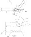
- FIG. 1A posterior view of an exemplary embodiment of the cervical fixation system, showing only the skeletal system of the subject.
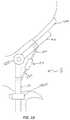
- FIG. 2A perspective view of an exemplary embodiment of the jointed spinal rod assembly.
- FIG. 3A side view of an exemplary embodiment of the jointed spinal rod assembly comprising a dipole magnet.
- FIG. 4A side view of an exemplary embodiment of the jointed spinal rod assembly comprising a quadrupole magnet.
- FIG. 5AA side view of an exemplary embodiment of the jointed spinal rod assembly, showing a cutaway of the adjustment mechanism.
- FIG. 5BA close-up cutaway view of an alternative embodiment of the adjustment mechanism.
- FIG. 6A caudal cross-sectional view of a subject with an exemplary embodiment of the cervical fixation system implanted in the subject, showing an embodiment of the controller positioned to cause rotation of the magnet in the jointed spinal rod.
- FIG. 7A flowchart of an exemplary embodiment of the method of fixing the relative positions of a cervical vertebra and an occipital bone in a subject.
- FIG. 8A side view of a subject with an exemplary embodiment of the cervical fixation system implanted in the subject, showing only the skeletal system of the subject.
- FIG. 9Detail of the embodiment of the jointed spinal rod assembly in the system shown in FIG. 8 .
- FIG. 10Detail of an alternative embodiment of the jointed spinal rod assembly.
- jointed spinal rod, systems, and methods for use thereofare described below.
- FIG. 1Illustrative embodiments of a jointed spinal rod, systems, and methods for use thereof, are described below.
- inventive features and componentsthat warrant patent protection, both individually and in combination.
- a jointed spinal rod assembly 5is provided, capable of being adjusted in angularity postoperatively without further surgeries.
- a general embodiment of the jointed rod assembly 5comprises a caudal rod portion 10 connected to an adjustment mechanism 20 , and a cranial rod portion 30 connected to the adjustment mechanism 20 .
- the adjustment mechanism 20is configured to rotate the caudal 10 and cranial 30 rod portions relative to one another about a joint axis that is generally perpendicular to the longitudinal axes of the caudal and cranial rod portions.
- the caudal 10 and cranial 30 rod portionsmay be dimensioned to be compatible with other pieces of hardware commonly used for spinal fixation, such as bone anchors (e.g., pedicle screws), occipital plates, reducers, and others.
- the caudal 10 and cranial 30 rod portionsare composed of a strong, rigid, non-absorbable, biocompatible material. Specific examples of such suitable materials include titanium, alloys of titanium, steel, and stainless steel. Parts of the jointed spinal rod 5 could conceivably be made from non-metallic biocompatible materials, which include aluminum oxide, calcium oxide, calcium phosphate, hydroxyapatite, zirconium oxide, and polymers such as polypropylene.
- the cranial 30 and caudal 10 rod portionswill generally be dimensioned to reach a cervical vertebra in a subject (on the caudal side) and reach the occipital bone of the subject (on the cranial side). These lengths will of course vary depending on the size of the subject, and may be customized for a given subject. In some embodiments, such lengths could be sufficient to extend from the occipital bone 50 to a cervical vertebra of a pediatric patient. In other such embodiments the lengths could be sufficient to extend from the occipital bone 50 to a cervical vertebra of an adult patient.
- Some embodiments of the adjustment mechanism 20are configured to rotate when exposed to a rotating magnetic field; this can be accomplished by various means. Some embodiments of the adjustment mechanism 20 are operatively linked to a first rotatable magnet 60 configured to rotate when exposed to a rotating magnetic field, such that the adjustment mechanism 20 is configured to rotate the caudal rod portion 10 about the joint axis relative to the cranial rod portion 30 in response to the rotation of the rotatable magnet 60 .
- the magnet 60is composed of a magnetic material, such as a ferromagnetic material.
- the rotatable magnet 60may have at least one circular cross-section 100 to enable it to rotate smoothly inside of a housing 80 (e.g., a sphere, cylinder, disc, cone, ellipsoid, etc.)
- the rotatable magnet 60may in some cases be mounted within the jointed rod 5 .
- the first magnet 60is a disc-shaped dipole magnet, mounted within the joint 160 with an axis of rotation perpendicular to longitudinal axes of both the caudal and cranial rods.
- FIG. 3the first magnet 60 is a disc-shaped dipole magnet, mounted within the joint 160 with an axis of rotation perpendicular to longitudinal axes of both the caudal and cranial rods.
- the first magnet 60is a disc-shaped quadrupole magnet, also mounted within the joint 160 with an axis of rotation perpendicular to longitudinal axes of both the caudal and cranial rods ( 10 and 30 , respectively).
- the first magnet 60is any multipolar magnet.
- a magnetic immobilization plate 120may be positioned, sufficiently close to the rotatable magnet 60 to cause the rotatable magnet 60 to adhere to the immobilization plate 120 in the absence of a strong external magnetic field.
- the magnetic immobilization plate 120will hold the rotating magnet 60 in position, preventing it from rotating, until a stronger magnetic field is applied, such as the rotating magnetic field that is used to adjust the relative orientations of the cranial and caudal rods ( 30 and 10 , respectively).
- the immobilization plate 120may be constructed from a suitable magnetic material, such as a ferromagnetic material.
- adjustment mechanism 20allow relative rotation of the caudal and cranial rod portions ( 10 , 30 ) about exactly one axis, like a hinge. Further embodiments may allow relative rotation of the two portions about more than one axis. Embodiments that allow relative rotation about exactly one axis have the advantage of stability, whereas embodiments that allow relative rotation about more than one axis have the advantage of flexibility. Accordingly, rotation may be achieved using a single actuator or multiple actuators.
- the adjustment mechanism 20connects to the caudal and cranial rods ( 10 , 30 ) above the joint 160 by a pair of linkage arms 130 .
- the combined length of the two linkage arms 130is adjusted in response to a rotating magnetic field, such that elongation of their combined length causes the 20 relative angle between the cranial 30 and caudal 10 portions to increase, and such that shortening of their combined length causes the relative angle between the cranial 30 and caudal 10 portions to decrease.
- Adjustment of the linkage arms 130may be achieved using a rotatable magnet 60 , configured to change the combined lengths of the linkage arms 130 when it rotates.
- the rotatable magnet 60could drive a threaded shaft at the end of 25 one or both linkage arms 130
- the housing 80 of the adjustment mechanism 20could include a threaded orifice engaged to the threaded shaft.
- the adjustment mechanism 20comprising the first magnet 60
- the non-magnetic or weakly magnetic materialwill not interfere with the motion of the first magnet 60 when exposed to an external rotating magnetic field.
- specific examples of such nonmagnetic non-absorbable biocompatible materialinclude titanium, alloys of titanium, aluminum oxide, calcium oxide, calcium phosphate, hydroxyapatite, zirconium oxide, and polymers such as polypropylene.
- weakly magnetic materialsinclude paramagnetic materials and diamagnetic materials.
- the weakly magnetic materialis austenitic stainless steel.
- the first magnet 60directly drives the joint.
- the first magnet 60may also drive the joint 160 indirectly.
- the first magnet 60may drive the joint 160 by means of a gear train 170 .
- the use of a gear train 170has the advantage of allowing an unequal ratio between the angular motion of the magnet 60 and the angular motion of the joint 160 .
- the gear ratiois less than 1:1 (joint 160 :magnet 60 )
- delicate changes in the angulation of the jointed rod 5may be accomplished, and increased torque may be realized with less force.
- the gear ratiois greater than 1:1, the angulation of the jointed rod 5 may be accomplished at greater speeds with less torque.
- FIG. 5AA specific example of an adjustment mechanism 20 with a gear train 170 is shown in FIG. 5A .
- the illustrated embodimentcomprises a cylindrical magnet 180 mounted to rotate about an axis that is parallel to the longitudinal axis of the caudal rod portion 10 .
- the cylindrical magnet 180spins a coaxial threaded rod 200 (such as a screw or a worm) that is engaged to a toothed wheel 210 (such as a gear or worm wheel), the toothed wheel 210 having an axis perpendicular to the axes of the magnet 180 and the threaded rod 200 .
- rotation of the magnet 180drives rotation of the threaded rod 200 , which in turn drives rotation of the toothed wheel 210 at a perpendicular axis.
- the cranial rod portion 30is connected to the joint 160 by a fulcrum or an axle 230 (such as a pin) near its caudal end 225 .
- the caudal end 225 of the cranial rod portion 30has a series of grooves 235 that mate with the teeth 245 on the toothed wheel 210 , such that the rotation of the toothed wheel 210 causes the cranial rod portion 30 to rotate about the fulcrum or axle 230 , thus changing the relative angle between the caudal and cranial rod portions ( 10 , 30 ).
- FIGS. 5B and 9Additional examples of an adjustment mechanism 20 with a gear train 170 are shown in FIGS. 5B and 9 .
- the illustrated embodimentscomprise a cylindrical magnet 180 mounted to rotate about an axis that is parallel to the longitudinal axis of the caudal rod portion 10 .
- the cylindrical magnet 180spins a coaxial threaded rod 200 (such as a screw or a worm).
- the cranial rod portion 30is connected to the joint 160 by a fulcrum or an axle 230 (such as a pin) near its caudal end 225 .
- the threaded rod 200is directly engaged to the cranial rod portion 30 .
- the caudal end 225 of the cranial rod portion 30has a plurality of thread engagement features 240 , such as teeth or grooves, engaged to the threaded rod 200 .
- thread engagement features 240such as teeth or grooves
- the adjustment mechanism 20may comprise a locking mechanism to prevent any change in relative inclination between the caudal and cranial rod portions ( 10 , 30 ) when the locking mechanism is engaged, but allow such changes when not engaged.
- the locking mechanismmay be disengaged prior to adjustment and reengaged after adjustment.
- the locking mechanismmay also be controlled by an external drive device.
- a specific embodiment of the locking mechanismcomprises a magnetically driven set screw.
- the magnetically driven set screwmay be oriented such that the external drive controller can be positioned to drive only one of the set screw and first magnet 60 , and then repositioned to drive the other.
- the set screw and the first magnet 60may be oriented such that each is driven by magnetic fields with perpendicular orientations (such that the field driving the first magnet 60 will not rotate that set screw, and vice-versa).
- the locking mechanismmay be a set screw situated in the hinge joint 160 opposite the first magnet 60 .
- Complementary surfaces of the caudal rod portion 10 and the cranial rod portion 30may have ridged surfaces that interdigitate, thus resisting rotation, when pressed into contact with each other by the advancing set screw.
- a locking pin or shaftcould be advanced with the set screw into the hinge joint 160 to inhibit movement of the joint.
- Such a locking pin or shaftcould be driven directly by a locking magnet or driven by a locking magnet via a gear train 170 . Ratchet configurations that resist movement in one direction are also contemplated.
- the locking mechanismis capable of being engaged post-operatively. Further such embodiments may be capable of being disengaged post-operatively.
- the locking mechanismmay be positioned between two jointed spinal rods ( 305 , 310 ) with two corresponding adjustment mechanisms 20 , to lock (and optionally unlock) both simultaneously.
- An exemplary such embodimentincludes a cylindrical lock magnet with a longitudinal axis approximately perpendicular to the longitudinal axis of the caudal 10 and cranial 30 rods. The cylindrical lock magnet spins on its longitudinal axis when exposed to a rotating magnetic field, driving a set screw either directly or through a gear train 170 .
- the magnetically driven set screw(or other magnetically driven locking mechanism) may itself be held in place by a second magnetic immobilization plate.
- the second magnetic immobilization platewill hold the set screw in place by adhering magnetically to the set screw in the absence of a stronger magnetic field.
- a strong magnetic fieldsuch as the rotating magnetic field that drives the set screw
- the set screwwill not adhere to the second immobilization plate, and will be free to rotate.
- the first magnet 60may be driven by a rotating magnetic field that originates external to the subject. This may be accomplished using an external rotating magnet 330 or array of magnets, or using an electrically induced magnetic field.
- One embodiment of the external adjustment device 285illustrated in FIG. 6 , is configured for placement on or adjacent to the skin of the subject and includes at least one magnet 330 (“external magnet”) configured for rotation.
- the illustrated embodimentalso has a motor 340 configured to rotate the external magnet 330 , whereby rotation of the external magnet 330 effectuates rotational movement of the first magnet 60 of the adjustable rod and alters the angle ( ⁇ ).
- Other means of rotating the external magnet 330may of course be used. As shown in FIG.
- the external adjustment device 285may have two external magnets ( 330 a , 330 b ).
- the two external magnets ( 330 a , 330 b )may be configured to rotate at any suitable rate, and in a specific embodiment they are configured to rotate at the same rate.
- the external magnets ( 330 a , 330 b )are configured to rotate at the same rate such that the positive and negative poles of each external magnet ( 330 a , 330 b ) are aligned.
- the positive (“North”) pole of the first external magnet 330 awill be at 0° when the positive pole of the second external magnet 330 b is at 180°
- the negative (“South”) pole of the first external magnet 330 awill be at 180° when the negative pole of the second external magnet 330 b is at 0° (such a configuration is shown in FIG. 6 ). Because both external magnets ( 330 a , 330 b ) rotate in the same direction along parallel axes at the same rate this relative configuration will be preserved through multiple cycles.
- the jointed spinal rod 5may be used in a spinal fixation system 370 .
- the spinal fixation system 370may be a cervical fixation system 380 , for fixing the relative positions of a cervical vertebra and an occipital bone in a subject.
- the system 370comprises any embodiment of the jointed spinal rod assembly 5 described above, in which the spinal rod assembly 5 has a longitudinal length sufficient to extend from the vertebra to the occipital bone; a bone anchor 400 having a bone fastener 410 connected to a rod housing 80 , said rod housing 80 dimensioned to accept the caudal rod portion 10 of the spinal rod assembly 5 ; and an occipital plate member 430 having a fixation screw 440 , and a rod receiver 450 dimensioned to accept the cranial rod portion 30 of the spinal rod assembly 5 .
- the components of the system 370may be made of any non-absorbable biocompatible material, including those disclosed above as suitable for the jointed rod 5 . Exemplary embodiments of the system 370 are illustrated in FIGS. 1 and 8 (with detail of the adjustment mechanism 20 and the occipital 430 plate provided in FIG. 9 ).
- FIGS. 1 and 8illustrate an embodiment of a posterior cervical fixation system installed in across the occipital-cervical junction.
- the cervical fixation system 380may be bilateral, comprising two generally parallel rods ( 305 , 310 ) running on the posterior surface of the spine.
- the illustrated embodiment of the systemcomprises a pair of elongated spinal rods ( 305 , 310 ), an occipital plate 430 , three cross connectors 470 , and a plurality of vertebral anchors 480 (pedicle screws in the illustrated embodiments).
- the posterior cervical fixation system 380 described hereinis for attachment to the posterior part of the human spine from the occipital bone to the cervical and/or thoracic vertebrae.
- the systemmay include two jointed rods on either side of the spinous processes, which share a common adjustment mechanism.
- the adjustment mechanismis positioned between the two jointed spinal rods, and contains the first magnetic positioned to rotate about an axis that is approximately parallel to the rotation axes of the two joints.
- the systemmay include two rigid spinal rods that connect to a single jointed spinal rod at the cephalad end, and the single jointed spinal rod connects both sides of the bilateral construct to the skull.
- the occipital plate member 430will be attached to the occipital bone. Such attachment may be achieved by various means, including via a fixation screw 440 . Multiple fixation screws 440 may be used to attach the occipital plate member 430 more securely.
- the occipital plate member 430includes a rod receiver 450 dimensioned to accept the cranial rod portion 30 of the spinal rod assembly 5 .
- Bilateral embodiments of the fixation systemmay comprise a pair of rod receivers ( 450 a , 450 b ) dimensioned to receive first 305 and second 310 adjustable spinal rods, respectively.
- the rod receiver 450 or receiversmay comprise one or more clamping elements 490 to secure the rod to the plate 430 .
- the bone anchor 400comprises a rod housing 80 configured to accept the caudal rod portion 10 , where they may be seated and fastened.
- a plurality of cross-connectors 470are fastened to the first 305 and second 310 rods, providing lateral stability to the system.
- the cross-connector 470may be dimensioned to fit between two spinous processes of the subject, as shown in FIG. 1 .
- a method of fixing the relative positions of a cervical vertebra and an occipital bone in a subjectis provided using the jointed rod disclosed above.
- Any embodiment of the rod described above that incorporates the first magnetmay be employed in the method.
- the methodcomprises fastening a bone anchor to the cervical vertebra of the subject; fastening an occipital plate member to the occipital bone of the subject; connecting the jointed spinal rod assembly to the bone anchor via the caudal rod portion and to the occipital plate via the cranial rod portion; and adjusting the relative inclination of the caudal rod portion of the spinal rod assembly to the cranial rod portion of the rod assembly by exposing the first magnet to a rotating magnetic field of sufficient strength to cause the caudal rod portion to rotate relative to the cranial rod portion.
- the methodmay involve the use of a bilateral construct, such as that shown in FIG. 1 .
- a bilateral constructsuch as that shown in FIG. 1 .
- Such embodiments of the methodwill comprise fastening at least a second bone anchor to the cervical vertebra, and may comprise fastening additional bone anchors to other vertebrae.
- Methods of bilateral fixationwill also comprise connecting a second jointed spinal rod assembly (which may be any embodiment of the jointed spinal rod described above) to the second bone anchor and the occipital plate.
- the second jointed spinal rodis connected to the second bone anchor via the caudal rod portion, and connected to the occipital plate via the cranial rod portion.
- the relative inclination of the cranial and caudal rod portions of the second jointed rod assemblyare also adjusted by exposure to a rotating magnetic field. Although such adjustment may occur at any time, in some embodiments of the method adjustment is performed post-operatively. Post-operative adjustment may be performed while the subject is conscious. In a specific embodiment, post-operative adjustment is performed post-operatively but prior to fusion.
- the methodmay comprise engaging the locking mechanism in the jointed spinal rod after adjusting the relative inclination of the caudal rod portion of the spinal rod assembly to the cranial rod portion of the rod assembly. This may be accomplished by exposing the locking mechanism to a remote signal, such as a rotating magnetic field. Although such locking may occur at any time, in some embodiments of the method locking is performed post-operatively. Post-operative locking may be performed while the subject is conscious. In a specific embodiment, post-operative locking is performed post-operatively but prior to fusion. In further embodiments the locking mechanism may be disengaged post-operatively. For example, the joint might be locked during surgery, unlocked post-operatively to allow adjustment of the rod, and then locked again once proper adjustment has been achieved. Alternatively, the rod may remain unlocked for the duration of surgery, and then only locked after post-operative adjustment has been completed (or after a post-operative evaluation concludes that no adjustment is needed).
- the post-operative adjustment of the jointed rod assemblywill have the effect of adjusting the inclination of the subject's head relative to the neck or thorax. Among other things, this determines the vertical angle of the subject's gaze, which controls the scope of the subject's gaze. The scope of the subject's gaze in turn affects the subject's ability to sense his or her surroundings. Consequently it is desirable to assess the angle of the subject's head and the subject's neutral gaze (the direction of the patient's gaze when the eyes are pointed directly ahead relative to the head) before adjusting the angle of the jointed spinal rod.
- an embodiment of the external controllermay be brought into proximity with the jointed rod assembly and the controller's external magnets may be rotated. This creates a rotating magnetic field that causes the jointed rod assembly to change its angulation. Depending on whether the angle of the head needs to be increased or decreased, the external magnet or magnets will be rotated in one direction or another.
- FIG. 7A flowchart of an exemplary embodiment of the method is shown in FIG. 7 .
- any given elements of the disclosed embodiments of the inventionmay be embodied in a single structure, a single step, a single substance, or the like.
- a given element of the disclosed embodimentmay be embodied in multiple structures, steps, substances, or the like.
Landscapes
- Health & Medical Sciences (AREA)
- Orthopedic Medicine & Surgery (AREA)
- Surgery (AREA)
- Neurology (AREA)
- Life Sciences & Earth Sciences (AREA)
- Medical Informatics (AREA)
- Animal Behavior & Ethology (AREA)
- Engineering & Computer Science (AREA)
- Biomedical Technology (AREA)
- Heart & Thoracic Surgery (AREA)
- Veterinary Medicine (AREA)
- Molecular Biology (AREA)
- Nuclear Medicine, Radiotherapy & Molecular Imaging (AREA)
- General Health & Medical Sciences (AREA)
- Public Health (AREA)
- Neurosurgery (AREA)
- Physics & Mathematics (AREA)
- Electromagnetism (AREA)
- Prostheses (AREA)
- Surgical Instruments (AREA)
Abstract
Description
Claims (19)
Priority Applications (4)
| Application Number | Priority Date | Filing Date | Title |
|---|---|---|---|
| US15/432,656US10610261B2 (en) | 2016-02-12 | 2017-02-14 | Post-operatively adjustable angled rod |
| US16/800,848US11446063B2 (en) | 2016-02-12 | 2020-02-25 | Post-operatively adjustable angled rod |
| US17/819,714US12156678B2 (en) | 2016-02-12 | 2022-08-15 | Post-operatively adjustable angled rod |
| US18/941,006US20250064486A1 (en) | 2016-02-12 | 2024-11-08 | Post-operatively adjustable angled rod |
Applications Claiming Priority (3)
| Application Number | Priority Date | Filing Date | Title |
|---|---|---|---|
| US201662294988P | 2016-02-12 | 2016-02-12 | |
| PCT/US2017/017697WO2017139782A1 (en) | 2016-02-12 | 2017-02-13 | Post-operatively adjustable angled rod |
| US15/432,656US10610261B2 (en) | 2016-02-12 | 2017-02-14 | Post-operatively adjustable angled rod |
Related Parent Applications (1)
| Application Number | Title | Priority Date | Filing Date |
|---|---|---|---|
| PCT/US2017/017697ContinuationWO2017139782A1 (en) | 2016-02-12 | 2017-02-13 | Post-operatively adjustable angled rod |
Related Child Applications (1)
| Application Number | Title | Priority Date | Filing Date |
|---|---|---|---|
| US16/800,848ContinuationUS11446063B2 (en) | 2016-02-12 | 2020-02-25 | Post-operatively adjustable angled rod |
Publications (2)
| Publication Number | Publication Date |
|---|---|
| US20170231664A1 US20170231664A1 (en) | 2017-08-17 |
| US10610261B2true US10610261B2 (en) | 2020-04-07 |
Family
ID=58094544
Family Applications (3)
| Application Number | Title | Priority Date | Filing Date |
|---|---|---|---|
| US15/432,656ActiveUS10610261B2 (en) | 2016-02-12 | 2017-02-14 | Post-operatively adjustable angled rod |
| US17/819,714Active2037-07-25US12156678B2 (en) | 2016-02-12 | 2022-08-15 | Post-operatively adjustable angled rod |
| US18/941,006PendingUS20250064486A1 (en) | 2016-02-12 | 2024-11-08 | Post-operatively adjustable angled rod |
Family Applications After (2)
| Application Number | Title | Priority Date | Filing Date |
|---|---|---|---|
| US17/819,714Active2037-07-25US12156678B2 (en) | 2016-02-12 | 2022-08-15 | Post-operatively adjustable angled rod |
| US18/941,006PendingUS20250064486A1 (en) | 2016-02-12 | 2024-11-08 | Post-operatively adjustable angled rod |
Country Status (3)
| Country | Link |
|---|---|
| US (3) | US10610261B2 (en) |
| EP (1) | EP3413819B1 (en) |
| WO (1) | WO2017139782A1 (en) |
Cited By (3)
| Publication number | Priority date | Publication date | Assignee | Title |
|---|---|---|---|---|
| US11364055B2 (en) | 2020-09-02 | 2022-06-21 | Zavation, Llc | Occipital plate and hinged rod assembly |
| US11446063B2 (en)* | 2016-02-12 | 2022-09-20 | Nuvasive, Inc. | Post-operatively adjustable angled rod |
| US12156678B2 (en) | 2016-02-12 | 2024-12-03 | Globus Medical Inc. | Post-operatively adjustable angled rod |
Families Citing this family (3)
| Publication number | Priority date | Publication date | Assignee | Title |
|---|---|---|---|---|
| US10898253B2 (en) | 2019-02-13 | 2021-01-26 | Loubert S. Suddaby | Anterior and lateral spinal retractor system with pivotable k-wire |
| CN111759438B (en)* | 2020-08-10 | 2025-05-20 | 北京市富乐科技开发有限公司 | Rear path reset internal fixation system |
| CN114668473B (en)* | 2022-03-03 | 2025-08-08 | 北京纳通医疗科技控股有限公司 | Connecting rod with adjustable curvature |
Citations (54)
| Publication number | Priority date | Publication date | Assignee | Title |
|---|---|---|---|---|
| US1365532A (en) | 1920-06-08 | 1921-01-11 | Herbert G Mountain | Hinge-joint for artificial limbs |
| US2077844A (en) | 1934-09-29 | 1937-04-20 | Leighton John Wycliffe | Adjustable hinge joint |
| US3342922A (en) | 1963-10-09 | 1967-09-19 | Dow Chemical Co | Method of preparing re-expandable foam |
| US3385615A (en) | 1966-05-10 | 1968-05-28 | Ashtabula Bow Socket Company | Steering post |
| US3816854A (en) | 1973-07-03 | 1974-06-18 | A Schlein | Prosthesis for total arthroplasty of the elbow joint |
| US4433677A (en) | 1981-05-29 | 1984-02-28 | Max Bernhard Ulrich | Implantable splint for correcting lumbosacral spondylodesis |
| US5405347A (en) | 1993-02-12 | 1995-04-11 | Zimmer, Inc. | Adjustable connector for external fixation rods |
| US5509328A (en) | 1995-02-03 | 1996-04-23 | Lai; Yung-Hsin | Adjustable upright tube of a bicycle handlebar |
| US5643263A (en) | 1995-08-14 | 1997-07-01 | Simonson; Peter Melott | Spinal implant connection assembly |
| US5645544A (en) | 1995-09-13 | 1997-07-08 | Danek Medical, Inc. | Variable angle extension rod |
| US5662653A (en) | 1996-02-22 | 1997-09-02 | Pioneer Laboratories, Inc. | Surgical rod-to-bone attachment |
| US5947967A (en) | 1997-10-22 | 1999-09-07 | Sdgt Holdings, Inc. | Variable angle connector |
| US5984923A (en) | 1996-05-09 | 1999-11-16 | Science Et Medecine (Sem) | Anti-shifting system for spinal arthrodesis bar |
| US6007536A (en) | 1998-11-30 | 1999-12-28 | Yue; James J. | Variable angle blade plate for fixation of cancellous bone |
| US6183473B1 (en) | 1999-04-21 | 2001-02-06 | Richard B Ashman | Variable angle connection assembly for a spinal implant system |
| US6238396B1 (en) | 1999-10-07 | 2001-05-29 | Blackstone Medical, Inc. | Surgical cross-connecting apparatus and related methods |
| US6284014B1 (en) | 1994-01-19 | 2001-09-04 | Alyn Corporation | Metal matrix composite |
| US6296644B1 (en) | 1998-08-26 | 2001-10-02 | Jean Saurat | Spinal instrumentation system with articulated modules |
| US20020138077A1 (en) | 2001-03-26 | 2002-09-26 | Ferree Bret A. | Spinal alignment apparatus and methods |
| US6471703B1 (en) | 1999-04-21 | 2002-10-29 | Sdgi Holdings, Inc. | Variable angle connection assembly for a spinal implant system |
| US20020193794A1 (en) | 2001-06-18 | 2002-12-19 | Taylor Harold Sparr | Connection assembly for spinal implant systems |
| US6551318B1 (en) | 2000-07-26 | 2003-04-22 | Stahurski Consulting Inc. | Spinal column retaining apparatus |
| US6562038B1 (en) | 2000-03-15 | 2003-05-13 | Sdgi Holdings, Inc. | Spinal implant connection assembly |
| US20030171751A1 (en) | 2002-02-20 | 2003-09-11 | Stephen Ritland | Pedicle screw connector apparatus and method |
| US6620164B2 (en) | 2000-09-22 | 2003-09-16 | Showa Ika Kohgyo Co., Ltd. | Rod for cervical vertebra and connecting system thereof |
| US6626906B1 (en) | 2000-10-23 | 2003-09-30 | Sdgi Holdings, Inc. | Multi-planar adjustable connector |
| US6648887B2 (en) | 2002-01-23 | 2003-11-18 | Richard B. Ashman | Variable angle spinal implant connection assembly |
| US6652527B2 (en) | 1998-10-20 | 2003-11-25 | St. Francis Medical Technologies, Inc. | Supplemental spine fixation device and method |
| US6663632B1 (en) | 1998-05-19 | 2003-12-16 | Synthes (U.S.A.) | Osteosynthetic implant with an embedded hinge joint |
| US20040002708A1 (en) | 2002-05-08 | 2004-01-01 | Stephen Ritland | Dynamic fixation device and method of use |
| US20040015166A1 (en) | 2002-07-22 | 2004-01-22 | Gorek Josef E. | System and method for stabilizing the spine by securing spine stabilization rods in crossed disposition |
| US6685705B1 (en) | 2000-10-23 | 2004-02-03 | Sdgi Holdings, Inc. | Six-axis and seven-axis adjustable connector |
| US6689133B2 (en) | 1999-04-16 | 2004-02-10 | Sdgi Holdings, Inc. | Multi-axial bone anchor system |
| US20040039384A1 (en) | 2002-08-21 | 2004-02-26 | Boehm Frank H. | Device and method for pertcutaneous placement of lumbar pedicle screws and connecting rods |
| US20040133203A1 (en) | 2002-10-28 | 2004-07-08 | Young J Stewart | Multi-axial, cross-link connector system for spinal implants |
| US6872209B2 (en) | 2000-03-15 | 2005-03-29 | Sdgi Holdings, Inc. | Spinal implant connection assembly |
| US20050113835A1 (en) | 2003-11-14 | 2005-05-26 | Ashman Richard B. | Variable angle spinal implant connection assembly |
| US20050228376A1 (en) | 2004-03-31 | 2005-10-13 | Boomer Mark C | Adjustable-angle spinal fixation element |
| US7517359B2 (en) | 2005-12-20 | 2009-04-14 | Sdgi Holdings, Inc. | Vertebral rod assemblies and methods |
| US20100217271A1 (en)* | 2009-02-23 | 2010-08-26 | Ellipse Technologies, Inc. | Spinal distraction system |
| US20110087288A1 (en)* | 2007-10-24 | 2011-04-14 | Tara Stevenson | Surgical Fixation System and Related Methods |
| US8057472B2 (en) | 2007-10-30 | 2011-11-15 | Ellipse Technologies, Inc. | Skeletal manipulation method |
| US20120078306A1 (en)* | 2010-09-28 | 2012-03-29 | Lynch Bobby S | Bone fixation systems and methods |
| US8382756B2 (en) | 2008-11-10 | 2013-02-26 | Ellipse Technologies, Inc. | External adjustment device for distraction device |
| US8449543B2 (en) | 2009-09-04 | 2013-05-28 | Ellipse Technologies, Inc. | Bone growth device and method |
| US20140088649A1 (en) | 2012-09-24 | 2014-03-27 | Refai Technologies, Llc | Articulating spinal rod system |
| US8715159B2 (en) | 2006-10-20 | 2014-05-06 | Ellipse Technologies, Inc. | Adjustable implant and method of use |
| US8734488B2 (en) | 2010-08-09 | 2014-05-27 | Ellipse Technologies, Inc. | Maintenance feature in magnetic implant |
| US20140214083A1 (en)* | 2011-04-08 | 2014-07-31 | Aesculap Implant Systems, Llc | Articulating rod assembly |
| US20140228891A1 (en)* | 2013-02-14 | 2014-08-14 | Blackstone Medical, Inc. | Rod attachment assembly for occipital plate |
| US8852187B2 (en) | 2011-02-14 | 2014-10-07 | Ellipse Technologies, Inc. | Variable length device and method |
| US20150105826A1 (en)* | 2013-10-10 | 2015-04-16 | Ellipse Technologies, Inc. | Adjustable spinal implant |
| US9179938B2 (en) | 2013-03-08 | 2015-11-10 | Ellipse Technologies, Inc. | Distraction devices and method of assembling the same |
| US9770274B2 (en) | 2012-10-18 | 2017-09-26 | Nuvasive Specialized Orthopedics, Inc. | Intramedullary implants for replacing lost bone |
Family Cites Families (2)
| Publication number | Priority date | Publication date | Assignee | Title |
|---|---|---|---|---|
| US7887566B2 (en)* | 2004-09-16 | 2011-02-15 | Hynes Richard A | Intervertebral support device with bias adjustment and related methods |
| WO2017139782A1 (en) | 2016-02-12 | 2017-08-17 | Nuvasive, Inc. | Post-operatively adjustable angled rod |
- 2017
- 2017-02-13WOPCT/US2017/017697patent/WO2017139782A1/ennot_activeCeased
- 2017-02-13EPEP17706383.1Apatent/EP3413819B1/enactiveActive
- 2017-02-14USUS15/432,656patent/US10610261B2/enactiveActive
- 2022
- 2022-08-15USUS17/819,714patent/US12156678B2/enactiveActive
- 2024
- 2024-11-08USUS18/941,006patent/US20250064486A1/enactivePending
Patent Citations (68)
| Publication number | Priority date | Publication date | Assignee | Title |
|---|---|---|---|---|
| US1365532A (en) | 1920-06-08 | 1921-01-11 | Herbert G Mountain | Hinge-joint for artificial limbs |
| US2077844A (en) | 1934-09-29 | 1937-04-20 | Leighton John Wycliffe | Adjustable hinge joint |
| US3342922A (en) | 1963-10-09 | 1967-09-19 | Dow Chemical Co | Method of preparing re-expandable foam |
| US3385615A (en) | 1966-05-10 | 1968-05-28 | Ashtabula Bow Socket Company | Steering post |
| US3816854A (en) | 1973-07-03 | 1974-06-18 | A Schlein | Prosthesis for total arthroplasty of the elbow joint |
| US4433677A (en) | 1981-05-29 | 1984-02-28 | Max Bernhard Ulrich | Implantable splint for correcting lumbosacral spondylodesis |
| US5405347A (en) | 1993-02-12 | 1995-04-11 | Zimmer, Inc. | Adjustable connector for external fixation rods |
| US6284014B1 (en) | 1994-01-19 | 2001-09-04 | Alyn Corporation | Metal matrix composite |
| US5509328A (en) | 1995-02-03 | 1996-04-23 | Lai; Yung-Hsin | Adjustable upright tube of a bicycle handlebar |
| US5643263A (en) | 1995-08-14 | 1997-07-01 | Simonson; Peter Melott | Spinal implant connection assembly |
| US5885285A (en) | 1995-08-14 | 1999-03-23 | Simonson; Peter Melott | Spinal implant connection assembly |
| US5645544A (en) | 1995-09-13 | 1997-07-08 | Danek Medical, Inc. | Variable angle extension rod |
| US5662653A (en) | 1996-02-22 | 1997-09-02 | Pioneer Laboratories, Inc. | Surgical rod-to-bone attachment |
| US5984923A (en) | 1996-05-09 | 1999-11-16 | Science Et Medecine (Sem) | Anti-shifting system for spinal arthrodesis bar |
| US5947967A (en) | 1997-10-22 | 1999-09-07 | Sdgt Holdings, Inc. | Variable angle connector |
| US6663632B1 (en) | 1998-05-19 | 2003-12-16 | Synthes (U.S.A.) | Osteosynthetic implant with an embedded hinge joint |
| US6296644B1 (en) | 1998-08-26 | 2001-10-02 | Jean Saurat | Spinal instrumentation system with articulated modules |
| US6652527B2 (en) | 1998-10-20 | 2003-11-25 | St. Francis Medical Technologies, Inc. | Supplemental spine fixation device and method |
| US6007536A (en) | 1998-11-30 | 1999-12-28 | Yue; James J. | Variable angle blade plate for fixation of cancellous bone |
| US6689133B2 (en) | 1999-04-16 | 2004-02-10 | Sdgi Holdings, Inc. | Multi-axial bone anchor system |
| US6183473B1 (en) | 1999-04-21 | 2001-02-06 | Richard B Ashman | Variable angle connection assembly for a spinal implant system |
| US6402749B1 (en) | 1999-04-21 | 2002-06-11 | Sdgi Holdings, Inc. | Variable angle connection assembly for a spinal implant system |
| US6471703B1 (en) | 1999-04-21 | 2002-10-29 | Sdgi Holdings, Inc. | Variable angle connection assembly for a spinal implant system |
| US6238396B1 (en) | 1999-10-07 | 2001-05-29 | Blackstone Medical, Inc. | Surgical cross-connecting apparatus and related methods |
| US6562038B1 (en) | 2000-03-15 | 2003-05-13 | Sdgi Holdings, Inc. | Spinal implant connection assembly |
| US6872209B2 (en) | 2000-03-15 | 2005-03-29 | Sdgi Holdings, Inc. | Spinal implant connection assembly |
| US6551318B1 (en) | 2000-07-26 | 2003-04-22 | Stahurski Consulting Inc. | Spinal column retaining apparatus |
| US6832999B2 (en) | 2000-09-22 | 2004-12-21 | Showa Ika Kohgyo Co., Ltd. | Rod for cervical vertebra and connecting system thereof |
| US6620164B2 (en) | 2000-09-22 | 2003-09-16 | Showa Ika Kohgyo Co., Ltd. | Rod for cervical vertebra and connecting system thereof |
| US20030176863A1 (en) | 2000-09-22 | 2003-09-18 | Showa Ika Kohgyo Co., Ltd. | Rod for cervical vertebra and connecting system thereof |
| US20030176864A1 (en) | 2000-09-22 | 2003-09-18 | Showa Ika Kohgyo Co., Ltd. | Rod for cervical vertebra and connecting system thereof |
| US6626906B1 (en) | 2000-10-23 | 2003-09-30 | Sdgi Holdings, Inc. | Multi-planar adjustable connector |
| US6685705B1 (en) | 2000-10-23 | 2004-02-03 | Sdgi Holdings, Inc. | Six-axis and seven-axis adjustable connector |
| US20020138077A1 (en) | 2001-03-26 | 2002-09-26 | Ferree Bret A. | Spinal alignment apparatus and methods |
| US20030191473A1 (en) | 2001-06-18 | 2003-10-09 | Taylor Harold Sparr | Connection assembly for spinal implant systems |
| US6579292B2 (en) | 2001-06-18 | 2003-06-17 | Sdgi Holdings, Inc. | Connection assembly for spinal implant systems |
| US20020193794A1 (en) | 2001-06-18 | 2002-12-19 | Taylor Harold Sparr | Connection assembly for spinal implant systems |
| US6648887B2 (en) | 2002-01-23 | 2003-11-18 | Richard B. Ashman | Variable angle spinal implant connection assembly |
| US20030171751A1 (en) | 2002-02-20 | 2003-09-11 | Stephen Ritland | Pedicle screw connector apparatus and method |
| US20040002708A1 (en) | 2002-05-08 | 2004-01-01 | Stephen Ritland | Dynamic fixation device and method of use |
| US20040015166A1 (en) | 2002-07-22 | 2004-01-22 | Gorek Josef E. | System and method for stabilizing the spine by securing spine stabilization rods in crossed disposition |
| US20040039384A1 (en) | 2002-08-21 | 2004-02-26 | Boehm Frank H. | Device and method for pertcutaneous placement of lumbar pedicle screws and connecting rods |
| US20040133203A1 (en) | 2002-10-28 | 2004-07-08 | Young J Stewart | Multi-axial, cross-link connector system for spinal implants |
| US20050113835A1 (en) | 2003-11-14 | 2005-05-26 | Ashman Richard B. | Variable angle spinal implant connection assembly |
| US20050228376A1 (en) | 2004-03-31 | 2005-10-13 | Boomer Mark C | Adjustable-angle spinal fixation element |
| US7517359B2 (en) | 2005-12-20 | 2009-04-14 | Sdgi Holdings, Inc. | Vertebral rod assemblies and methods |
| US8715159B2 (en) | 2006-10-20 | 2014-05-06 | Ellipse Technologies, Inc. | Adjustable implant and method of use |
| US20110087288A1 (en)* | 2007-10-24 | 2011-04-14 | Tara Stevenson | Surgical Fixation System and Related Methods |
| US9179960B2 (en) | 2007-10-30 | 2015-11-10 | Ellipse Technologies, Inc. | Skeletal manipulation method |
| US8057472B2 (en) | 2007-10-30 | 2011-11-15 | Ellipse Technologies, Inc. | Skeletal manipulation method |
| US8419734B2 (en) | 2007-10-30 | 2013-04-16 | Ellipse Technologies, Inc. | Skeletal manipulation method |
| US8382756B2 (en) | 2008-11-10 | 2013-02-26 | Ellipse Technologies, Inc. | External adjustment device for distraction device |
| US8197490B2 (en) | 2009-02-23 | 2012-06-12 | Ellipse Technologies, Inc. | Non-invasive adjustable distraction system |
| US20100217271A1 (en)* | 2009-02-23 | 2010-08-26 | Ellipse Technologies, Inc. | Spinal distraction system |
| US9848914B2 (en) | 2009-02-23 | 2017-12-26 | Nuvasive Specialized Orthopedics, Inc. | Non-invasive adjustable distraction system |
| US8974463B2 (en) | 2009-02-23 | 2015-03-10 | Ellipse Technologies, Inc. | Non-invasive adjustable distraction system |
| US8449543B2 (en) | 2009-09-04 | 2013-05-28 | Ellipse Technologies, Inc. | Bone growth device and method |
| US8734488B2 (en) | 2010-08-09 | 2014-05-27 | Ellipse Technologies, Inc. | Maintenance feature in magnetic implant |
| US9757159B2 (en) | 2010-08-09 | 2017-09-12 | Nuvasive Specialized Orthopedics, Inc. | Maintenance feature in magnetic implant |
| US9186183B2 (en) | 2010-08-09 | 2015-11-17 | Ellipse Technologies, Inc. | Maintenance feature in magnetic implant |
| US20120078306A1 (en)* | 2010-09-28 | 2012-03-29 | Lynch Bobby S | Bone fixation systems and methods |
| US8852187B2 (en) | 2011-02-14 | 2014-10-07 | Ellipse Technologies, Inc. | Variable length device and method |
| US20140214083A1 (en)* | 2011-04-08 | 2014-07-31 | Aesculap Implant Systems, Llc | Articulating rod assembly |
| US20140088649A1 (en) | 2012-09-24 | 2014-03-27 | Refai Technologies, Llc | Articulating spinal rod system |
| US9770274B2 (en) | 2012-10-18 | 2017-09-26 | Nuvasive Specialized Orthopedics, Inc. | Intramedullary implants for replacing lost bone |
| US20140228891A1 (en)* | 2013-02-14 | 2014-08-14 | Blackstone Medical, Inc. | Rod attachment assembly for occipital plate |
| US9179938B2 (en) | 2013-03-08 | 2015-11-10 | Ellipse Technologies, Inc. | Distraction devices and method of assembling the same |
| US20150105826A1 (en)* | 2013-10-10 | 2015-04-16 | Ellipse Technologies, Inc. | Adjustable spinal implant |
Non-Patent Citations (2)
| Title |
|---|
| International Search Report dated Aug. 17, 2017 for International Application No. PCT/US2017/017697, 8 pages. |
| Written Opinion of the International Searching Authority dated Aug. 17, 2017 for International Application No. PCT/US2017/017697, 11 pages. |
Cited By (3)
| Publication number | Priority date | Publication date | Assignee | Title |
|---|---|---|---|---|
| US11446063B2 (en)* | 2016-02-12 | 2022-09-20 | Nuvasive, Inc. | Post-operatively adjustable angled rod |
| US12156678B2 (en) | 2016-02-12 | 2024-12-03 | Globus Medical Inc. | Post-operatively adjustable angled rod |
| US11364055B2 (en) | 2020-09-02 | 2022-06-21 | Zavation, Llc | Occipital plate and hinged rod assembly |
Also Published As
| Publication number | Publication date |
|---|---|
| WO2017139782A1 (en) | 2017-08-17 |
| US20170231664A1 (en) | 2017-08-17 |
| EP3413819B1 (en) | 2022-07-06 |
| US12156678B2 (en) | 2024-12-03 |
| EP3413819A1 (en) | 2018-12-19 |
| US20250064486A1 (en) | 2025-02-27 |
| US20220387078A1 (en) | 2022-12-08 |
Similar Documents
| Publication | Publication Date | Title |
|---|---|---|
| US12156678B2 (en) | Post-operatively adjustable angled rod | |
| US11826078B2 (en) | Post-operatively adjustable spinal fixation devices | |
| US7901433B2 (en) | Occipito-cervical stabilization system and method | |
| CN108498150B (en) | Spinal implant system and method | |
| US9649133B2 (en) | Supplemental fixation screw | |
| US6533790B1 (en) | Self-guided pedical screw | |
| US11426209B2 (en) | Spinal implant system and methods of use | |
| US20090125067A1 (en) | In-line occipital plate and method of use | |
| US12161368B2 (en) | Magnetically actuatable rod insertion for minimally invasive surgery | |
| EP4262594B1 (en) | Adjustable spinal implant system | |
| US20230094426A1 (en) | Device and treatment of abnormal spine curvature | |
| US11446063B2 (en) | Post-operatively adjustable angled rod | |
| US20160128734A1 (en) | Threaded Setscrew Crosslink | |
| US20120116458A1 (en) | Modular pivotable screw assembly and method | |
| US11350969B1 (en) | Rotatable spinal implant, system, and method | |
| CN117064526A (en) | Spinal implant systems and methods | |
| WO2017139780A1 (en) | Magnetically actuateable rod insertion for minimally invasive surgery |
Legal Events
| Date | Code | Title | Description |
|---|---|---|---|
| AS | Assignment | Owner name:BANK OF AMERICA, N.A., AS ADMINISTRATIVE AGENT, TEXAS Free format text:NOTICE OF GRANT OF SECURITY INTEREST IN PATENTS;ASSIGNORS:NUVASIVE, INC.;BIOTRONIC NATIONAL, LLC;NUVASIVE CLINICAL SERVICES MONITORING, INC.;AND OTHERS;REEL/FRAME:042490/0236 Effective date:20170425 Owner name:BANK OF AMERICA, N.A., AS ADMINISTRATIVE AGENT, TE Free format text:NOTICE OF GRANT OF SECURITY INTEREST IN PATENTS;ASSIGNORS:NUVASIVE, INC.;BIOTRONIC NATIONAL, LLC;NUVASIVE CLINICAL SERVICES MONITORING, INC.;AND OTHERS;REEL/FRAME:042490/0236 Effective date:20170425 | |
| AS | Assignment | Owner name:NUVASIVE, INC., CALIFORNIA Free format text:ASSIGNMENT OF ASSIGNORS INTEREST;ASSIGNORS:DOOSE, JUSTIN;OJEDA, MARK;JACOBS, MATTHEW TOBIAS;SIGNING DATES FROM 20180523 TO 20180901;REEL/FRAME:047042/0429 | |
| STCB | Information on status: application discontinuation | Free format text:ABANDONED -- FAILURE TO RESPOND TO AN OFFICE ACTION | |
| STPP | Information on status: patent application and granting procedure in general | Free format text:RESPONSE TO NON-FINAL OFFICE ACTION ENTERED AND FORWARDED TO EXAMINER | |
| STPP | Information on status: patent application and granting procedure in general | Free format text:FINAL REJECTION MAILED | |
| STPP | Information on status: patent application and granting procedure in general | Free format text:NOTICE OF ALLOWANCE MAILED -- APPLICATION RECEIVED IN OFFICE OF PUBLICATIONS | |
| STPP | Information on status: patent application and granting procedure in general | Free format text:PUBLICATIONS -- ISSUE FEE PAYMENT RECEIVED | |
| AS | Assignment | Owner name:BANK OF AMERICA, N.A., AS ADMINISTRATIVE AGENT, NORTH CAROLINA Free format text:SECURITY INTEREST;ASSIGNORS:NUVASIVE, INC.;NUVASIVE CLINICAL SERVICES MONITORING, INC.;NUVASIVE CLINICAL SERVICES, INC.;AND OTHERS;REEL/FRAME:052918/0595 Effective date:20200224 | |
| STCF | Information on status: patent grant | Free format text:PATENTED CASE | |
| MAFP | Maintenance fee payment | Free format text:PAYMENT OF MAINTENANCE FEE, 4TH YEAR, LARGE ENTITY (ORIGINAL EVENT CODE: M1551); ENTITY STATUS OF PATENT OWNER: LARGE ENTITY Year of fee payment:4 |