US10610231B2 - Filamentary devices for treatment of vascular defects - Google Patents
Filamentary devices for treatment of vascular defectsDownload PDFInfo
- Publication number
- US10610231B2 US10610231B2US15/656,879US201715656879AUS10610231B2US 10610231 B2US10610231 B2US 10610231B2US 201715656879 AUS201715656879 AUS 201715656879AUS 10610231 B2US10610231 B2US 10610231B2
- Authority
- US
- United States
- Prior art keywords
- filaments
- permeable shell
- aneurysm
- microcatheter
- patient
- Prior art date
- Legal status (The legal status is an assumption and is not a legal conclusion. Google has not performed a legal analysis and makes no representation as to the accuracy of the status listed.)
- Active, expires
Links
- 238000011282treatmentMethods0.000titleclaimsabstractdescription103
- 230000007556vascular defectEffects0.000titledescription123
- 206010002329AneurysmDiseases0.000claimsabstractdescription91
- 210000005166vasculatureAnatomy0.000claimsabstractdescription85
- 238000000034methodMethods0.000claimsabstractdescription63
- 201000008450Intracranial aneurysmDiseases0.000claimsabstractdescription23
- 230000002490cerebral effectEffects0.000claimsabstractdescription7
- 210000001627cerebral arteryAnatomy0.000claimsabstractdescription6
- 239000007943implantSubstances0.000claimsdescription12
- 238000002513implantationMethods0.000claimsdescription7
- UQMRAFJOBWOFNS-UHFFFAOYSA-Nbutyl 2-(2,4-dichlorophenoxy)acetateChemical compoundCCCCOC(=O)COC1=CC=C(Cl)C=C1ClUQMRAFJOBWOFNS-UHFFFAOYSA-N0.000description92
- 239000000463materialSubstances0.000description44
- 230000007547defectEffects0.000description36
- 239000011148porous materialSubstances0.000description27
- 230000002792vascularEffects0.000description21
- 210000004369bloodAnatomy0.000description18
- 239000008280bloodSubstances0.000description18
- 239000000835fiberSubstances0.000description18
- 238000000576coating methodMethods0.000description17
- -1polyethylenePolymers0.000description16
- 229920000642polymerPolymers0.000description16
- 230000002441reversible effectEffects0.000description16
- 210000004204blood vesselAnatomy0.000description14
- 210000001519tissueAnatomy0.000description14
- 238000007789sealingMethods0.000description13
- 230000017531blood circulationEffects0.000description12
- 230000007246mechanismEffects0.000description12
- 238000009954braidingMethods0.000description11
- 229910052751metalInorganic materials0.000description11
- 239000002184metalSubstances0.000description11
- 239000011248coating agentSubstances0.000description10
- 230000008569processEffects0.000description10
- 230000001732thrombotic effectEffects0.000description10
- 208000007536ThrombosisDiseases0.000description9
- 229910045601alloyInorganic materials0.000description9
- 239000000956alloySubstances0.000description9
- 239000003795chemical substances by applicationSubstances0.000description9
- 239000004020conductorSubstances0.000description9
- 230000003073embolic effectEffects0.000description9
- 210000004556brainAnatomy0.000description8
- 230000035602clottingEffects0.000description8
- 238000004519manufacturing processMethods0.000description8
- 229910001000nickel titaniumInorganic materials0.000description8
- 230000001154acute effectEffects0.000description7
- 230000035876healingEffects0.000description7
- 238000010438heat treatmentMethods0.000description7
- 206010053567CoagulopathiesDiseases0.000description6
- MWUXSHHQAYIFBG-UHFFFAOYSA-NNitric oxideChemical compoundO=[N]MWUXSHHQAYIFBG-UHFFFAOYSA-N0.000description6
- 210000004027cellAnatomy0.000description6
- 229920001577copolymerPolymers0.000description6
- 239000012530fluidSubstances0.000description6
- 150000002739metalsChemical class0.000description6
- 230000036961partial effectEffects0.000description6
- 238000004381surface treatmentMethods0.000description6
- 238000001356surgical procedureMethods0.000description6
- 210000001367arteryAnatomy0.000description5
- 230000015572biosynthetic processEffects0.000description5
- 230000008859changeEffects0.000description5
- 239000002131composite materialSubstances0.000description5
- 239000003814drugSubstances0.000description5
- 230000006870functionEffects0.000description5
- 229920000728polyesterPolymers0.000description5
- 238000004513sizingMethods0.000description5
- 206010068149Vessel perforationDiseases0.000description4
- 239000012620biological materialSubstances0.000description4
- 230000000694effectsEffects0.000description4
- 230000010102embolizationEffects0.000description4
- 210000001105femoral arteryAnatomy0.000description4
- 238000009998heat settingMethods0.000description4
- 230000023597hemostasisEffects0.000description4
- 230000001788irregularEffects0.000description4
- BASFCYQUMIYNBI-UHFFFAOYSA-NplatinumChemical compound[Pt]BASFCYQUMIYNBI-UHFFFAOYSA-N0.000description4
- 230000001225therapeutic effectEffects0.000description4
- 230000002885thrombogenetic effectEffects0.000description4
- 238000003466weldingMethods0.000description4
- 102000008186CollagenHuman genes0.000description3
- 108010035532CollagenProteins0.000description3
- AEMRFAOFKBGASW-UHFFFAOYSA-NGlycolic acidChemical compoundOCC(O)=OAEMRFAOFKBGASW-UHFFFAOYSA-N0.000description3
- 229920000106Liquid crystal polymerPolymers0.000description3
- 239000004977Liquid-crystal polymers (LCPs)Substances0.000description3
- 229920000954PolyglycolidePolymers0.000description3
- 230000009471actionEffects0.000description3
- 239000000853adhesiveSubstances0.000description3
- 238000004026adhesive bondingMethods0.000description3
- 230000001070adhesive effectEffects0.000description3
- 238000013459approachMethods0.000description3
- 230000000975bioactive effectEffects0.000description3
- 230000005540biological transmissionEffects0.000description3
- 229920001436collagenPolymers0.000description3
- 238000005056compactionMethods0.000description3
- 238000010276constructionMethods0.000description3
- 229910003460diamondInorganic materials0.000description3
- 239000010432diamondSubstances0.000description3
- 229940079593drugDrugs0.000description3
- PCHJSUWPFVWCPO-UHFFFAOYSA-NgoldChemical compound[Au]PCHJSUWPFVWCPO-UHFFFAOYSA-N0.000description3
- 239000010931goldSubstances0.000description3
- 229910052737goldInorganic materials0.000description3
- 238000005259measurementMethods0.000description3
- 239000000203mixtureSubstances0.000description3
- 230000035699permeabilityEffects0.000description3
- 238000001259photo etchingMethods0.000description3
- 229920001610polycaprolactonePolymers0.000description3
- 239000004632polycaprolactoneSubstances0.000description3
- 230000002829reductive effectEffects0.000description3
- 230000004044responseEffects0.000description3
- 238000005476solderingMethods0.000description3
- XLYOFNOQVPJJNP-UHFFFAOYSA-NwaterSubstancesOXLYOFNOQVPJJNP-UHFFFAOYSA-N0.000description3
- FHVDTGUDJYJELY-UHFFFAOYSA-N6-{[2-carboxy-4,5-dihydroxy-6-(phosphanyloxy)oxan-3-yl]oxy}-4,5-dihydroxy-3-phosphanyloxane-2-carboxylic acidChemical compoundO1C(C(O)=O)C(P)C(O)C(O)C1OC1C(C(O)=O)OC(OP)C(O)C1OFHVDTGUDJYJELY-UHFFFAOYSA-N0.000description2
- 241000282465CanisSpecies0.000description2
- 208000005189EmbolismDiseases0.000description2
- 239000004593EpoxySubstances0.000description2
- 229920000219Ethylene vinyl alcoholPolymers0.000description2
- OHCQJHSOBUTRHG-KGGHGJDLSA-NFORSKOLINChemical compoundO=C([C@@]12O)C[C@](C)(C=C)O[C@]1(C)[C@@H](OC(=O)C)[C@@H](O)[C@@H]1[C@]2(C)[C@@H](O)CCC1(C)COHCQJHSOBUTRHG-KGGHGJDLSA-N0.000description2
- HTTJABKRGRZYRN-UHFFFAOYSA-NHeparinChemical compoundOC1C(NC(=O)C)C(O)OC(COS(O)(=O)=O)C1OC1C(OS(O)(=O)=O)C(O)C(OC2C(C(OS(O)(=O)=O)C(OC3C(C(O)C(O)C(O3)C(O)=O)OS(O)(=O)=O)C(CO)O2)NS(O)(=O)=O)C(C(O)=O)O1HTTJABKRGRZYRN-UHFFFAOYSA-N0.000description2
- 108010007267HirudinsProteins0.000description2
- 102000007625HirudinsHuman genes0.000description2
- 229920001410MicrofiberPolymers0.000description2
- 239000004696Poly ether ether ketoneSubstances0.000description2
- 239000004743PolypropyleneSubstances0.000description2
- 239000004372Polyvinyl alcoholSubstances0.000description2
- 206010053648Vascular occlusionDiseases0.000description2
- HZEWFHLRYVTOIW-UHFFFAOYSA-N[Ti].[Ni]Chemical compound[Ti].[Ni]HZEWFHLRYVTOIW-UHFFFAOYSA-N0.000description2
- 229920006397acrylic thermoplasticPolymers0.000description2
- 229940072056alginateDrugs0.000description2
- 229920000615alginic acidPolymers0.000description2
- 235000010443alginic acidNutrition0.000description2
- KXNPVXPOPUZYGB-XYVMCAHJSA-NargatrobanChemical compoundOC(=O)[C@H]1C[C@H](C)CCN1C(=O)[C@H](CCCN=C(N)N)NS(=O)(=O)C1=CC=CC2=C1NC[C@H](C)C2KXNPVXPOPUZYGB-XYVMCAHJSA-N0.000description2
- 229960003856argatrobanDrugs0.000description2
- 230000009286beneficial effectEffects0.000description2
- 235000021028berryNutrition0.000description2
- 239000012867bioactive agentSubstances0.000description2
- 230000000903blocking effectEffects0.000description2
- 238000007906compressionMethods0.000description2
- 230000006835compressionEffects0.000description2
- 239000002872contrast mediaSubstances0.000description2
- 229960002768dipyridamoleDrugs0.000description2
- IZEKFCXSFNUWAM-UHFFFAOYSA-NdipyridamoleChemical compoundC=12N=C(N(CCO)CCO)N=C(N3CCCCC3)C2=NC(N(CCO)CCO)=NC=1N1CCCCC1IZEKFCXSFNUWAM-UHFFFAOYSA-N0.000description2
- 238000009760electrical discharge machiningMethods0.000description2
- 229960001123epoprostenolDrugs0.000description2
- KAQKFAOMNZTLHT-VVUHWYTRSA-NepoprostenolChemical compoundO1C(=CCCCC(O)=O)C[C@@H]2[C@@H](/C=C/[C@@H](O)CCCCC)[C@H](O)C[C@@H]21KAQKFAOMNZTLHT-VVUHWYTRSA-N0.000description2
- 239000004715ethylene vinyl alcoholSubstances0.000description2
- 238000001125extrusionMethods0.000description2
- 239000003527fibrinolytic agentSubstances0.000description2
- 238000002594fluoroscopyMethods0.000description2
- 230000036541healthEffects0.000description2
- 229960002897heparinDrugs0.000description2
- 229920000669heparinPolymers0.000description2
- RZXDTJIXPSCHCI-UHFFFAOYSA-Nhexa-1,5-diene-2,5-diolChemical compoundOC(=C)CCC(O)=CRZXDTJIXPSCHCI-UHFFFAOYSA-N0.000description2
- WQPDUTSPKFMPDP-OUMQNGNKSA-NhirudinChemical compoundC([C@@H](C(=O)N[C@@H](CCC(O)=O)C(=O)N[C@@H](CCC(O)=O)C(=O)N[C@@H]([C@@H](C)CC)C(=O)N1[C@@H](CCC1)C(=O)N[C@@H](CCC(O)=O)C(=O)N[C@@H](CCC(O)=O)C(=O)N[C@@H](CC=1C=CC(OS(O)(=O)=O)=CC=1)C(=O)N[C@@H](CC(C)C)C(=O)N[C@@H](CCC(N)=O)C(O)=O)NC(=O)[C@H](CC(O)=O)NC(=O)CNC(=O)[C@H](CC(O)=O)NC(=O)[C@H](CC(N)=O)NC(=O)[C@H](CC=1NC=NC=1)NC(=O)[C@H](CO)NC(=O)[C@H](CCC(N)=O)NC(=O)[C@H]1N(CCC1)C(=O)[C@H](CCCCN)NC(=O)[C@H]1N(CCC1)C(=O)[C@@H](NC(=O)CNC(=O)[C@H](CCC(O)=O)NC(=O)CNC(=O)[C@@H](NC(=O)[C@@H](NC(=O)[C@H]1NC(=O)[C@H](CCC(N)=O)NC(=O)[C@H](CC(N)=O)NC(=O)[C@H](CCCCN)NC(=O)[C@H](CCC(O)=O)NC(=O)CNC(=O)[C@H](CC(O)=O)NC(=O)[C@H](CO)NC(=O)CNC(=O)[C@H](CC(C)C)NC(=O)[C@H]([C@@H](C)CC)NC(=O)[C@@H]2CSSC[C@@H](C(=O)N[C@@H](CCC(O)=O)C(=O)NCC(=O)N[C@@H](CO)C(=O)N[C@@H](CC(N)=O)C(=O)N[C@H](C(=O)N[C@H](C(NCC(=O)N[C@@H](CCC(N)=O)C(=O)NCC(=O)N[C@@H](CC(N)=O)C(=O)N[C@@H](CCCCN)C(=O)N2)=O)CSSC1)C(C)C)NC(=O)[C@H](CC(C)C)NC(=O)[C@H]1NC(=O)[C@H](CC(C)C)NC(=O)[C@H](CC(N)=O)NC(=O)[C@H](CCC(N)=O)NC(=O)CNC(=O)[C@H](CO)NC(=O)[C@H](CCC(O)=O)NC(=O)[C@H]([C@@H](C)O)NC(=O)[C@@H](NC(=O)[C@H](CC(O)=O)NC(=O)[C@@H](NC(=O)[C@H](CC=2C=CC(O)=CC=2)NC(=O)[C@@H](NC(=O)[C@@H](N)C(C)C)C(C)C)[C@@H](C)O)CSSC1)C(C)C)[C@@H](C)O)[C@@H](C)O)C1=CC=CC=C1WQPDUTSPKFMPDP-OUMQNGNKSA-N0.000description2
- 229940006607hirudinDrugs0.000description2
- 238000003384imaging methodMethods0.000description2
- 238000001727in vivoMethods0.000description2
- 238000003780insertionMethods0.000description2
- 230000037431insertionEffects0.000description2
- 230000003993interactionEffects0.000description2
- 238000002955isolationMethods0.000description2
- JVTAAEKCZFNVCJ-UHFFFAOYSA-Nlactic acidChemical compoundCC(O)C(O)=OJVTAAEKCZFNVCJ-UHFFFAOYSA-N0.000description2
- 239000007788liquidSubstances0.000description2
- 238000003754machiningMethods0.000description2
- 239000003550markerSubstances0.000description2
- 239000011159matrix materialSubstances0.000description2
- 238000002844meltingMethods0.000description2
- 230000008018meltingEffects0.000description2
- 239000003658microfiberSubstances0.000description2
- HLXZNVUGXRDIFK-UHFFFAOYSA-Nnickel titaniumChemical compound[Ti].[Ti].[Ti].[Ti].[Ti].[Ti].[Ti].[Ti].[Ti].[Ti].[Ti].[Ni].[Ni].[Ni].[Ni].[Ni].[Ni].[Ni].[Ni].[Ni].[Ni].[Ni].[Ni].[Ni].[Ni]HLXZNVUGXRDIFK-UHFFFAOYSA-N0.000description2
- 229910052697platinumInorganic materials0.000description2
- 229920001432poly(L-lactide)Polymers0.000description2
- 229920003229poly(methyl methacrylate)Polymers0.000description2
- 229920001692polycarbonate urethanePolymers0.000description2
- 229920002530polyetherether ketonePolymers0.000description2
- 239000004633polyglycolic acidSubstances0.000description2
- 239000004626polylactic acidSubstances0.000description2
- 229920001155polypropylenePolymers0.000description2
- 229920001296polysiloxanePolymers0.000description2
- 229920001343polytetrafluoroethylenePolymers0.000description2
- 239000004810polytetrafluoroethyleneSubstances0.000description2
- 239000004814polyurethaneSubstances0.000description2
- 229920002451polyvinyl alcoholPolymers0.000description2
- 108090000765processed proteins & peptidesProteins0.000description2
- 102000004196processed proteins & peptidesHuman genes0.000description2
- 102000004169proteins and genesHuman genes0.000description2
- 108090000623proteins and genesProteins0.000description2
- 210000002321radial arteryAnatomy0.000description2
- 238000007493shaping processMethods0.000description2
- 229910000679solderInorganic materials0.000description2
- 229910001220stainless steelInorganic materials0.000description2
- 239000010935stainless steelSubstances0.000description2
- 229910052715tantalumInorganic materials0.000description2
- GUVRBAGPIYLISA-UHFFFAOYSA-Ntantalum atomChemical compound[Ta]GUVRBAGPIYLISA-UHFFFAOYSA-N0.000description2
- ISXSCDLOGDJUNJ-UHFFFAOYSA-Ntert-butyl prop-2-enoateChemical compoundCC(C)(C)OC(=O)C=CISXSCDLOGDJUNJ-UHFFFAOYSA-N0.000description2
- 229940124597therapeutic agentDrugs0.000description2
- 239000010409thin filmSubstances0.000description2
- 208000021331vascular occlusion diseaseDiseases0.000description2
- KAGLWQUWUNBAOO-KSZLIROESA-N(2s)-n-[(2s)-5-(diaminomethylideneamino)-1-oxopentan-2-yl]-1-[(2r)-2-(methylamino)-3-phenylpropanoyl]pyrrolidine-2-carboxamideChemical compoundC([C@@H](NC)C(=O)N1[C@@H](CCC1)C(=O)N[C@@H](CCCN=C(N)N)C=O)C1=CC=CC=C1KAGLWQUWUNBAOO-KSZLIROESA-N0.000description1
- PWINFPFVCZSLBF-RTWAWAEBSA-N(3s)-4-[[(2r)-1-amino-3-cyclohexyl-1-oxopropan-2-yl]amino]-3-[[2-[ethyl(4-piperidin-4-ylbutanoyl)amino]acetyl]amino]-4-oxobutanoic acidChemical compoundC([C@@H](NC(=O)[C@H](CC(O)=O)NC(=O)CN(CC)C(=O)CCCC1CCNCC1)C(N)=O)C1CCCCC1PWINFPFVCZSLBF-RTWAWAEBSA-N0.000description1
- GQGRDYWMOPRROR-ZIFKCHSBSA-N(e)-7-[(1r,2r,3s,5s)-3-hydroxy-5-[(4-phenylphenyl)methoxy]-2-piperidin-1-ylcyclopentyl]hept-4-enoic acidChemical compoundO([C@H]1C[C@@H]([C@@H]([C@H]1CC\C=C\CCC(O)=O)N1CCCCC1)O)CC(C=C1)=CC=C1C1=CC=CC=C1GQGRDYWMOPRROR-ZIFKCHSBSA-N0.000description1
- PYZOVVQJTLOHDG-FQEVSTJZSA-N2-[(2s)-4-methyl-3-oxo-7-(4-piperidin-4-ylpiperidine-1-carbonyl)-2,5-dihydro-1h-1,4-benzodiazepin-2-yl]acetic acidChemical compoundO=C([C@H](CC(O)=O)NC1=CC=2)N(C)CC1=CC=2C(=O)N(CC1)CCC1C1CCNCC1PYZOVVQJTLOHDG-FQEVSTJZSA-N0.000description1
- 206010002091AnaesthesiaDiseases0.000description1
- BSYNRYMUTXBXSQ-UHFFFAOYSA-NAspirinChemical compoundCC(=O)OC1=CC=CC=C1C(O)=OBSYNRYMUTXBXSQ-UHFFFAOYSA-N0.000description1
- 239000005552B01AC04 - ClopidogrelSubstances0.000description1
- 239000005528B01AC05 - TiclopidineSubstances0.000description1
- 235000014036CastaneaNutrition0.000description1
- 241001070941CastaneaSpecies0.000description1
- 229920001661ChitosanPolymers0.000description1
- 229910000684Cobalt-chromeInorganic materials0.000description1
- SUZLHDUTVMZSEV-UHFFFAOYSA-NDeoxycoleonolNatural productsC12C(=O)CC(C)(C=C)OC2(C)C(OC(=O)C)C(O)C2C1(C)C(O)CCC2(C)CSUZLHDUTVMZSEV-UHFFFAOYSA-N0.000description1
- 229920002307DextranPolymers0.000description1
- 102000016942ElastinHuman genes0.000description1
- 108010014258ElastinProteins0.000description1
- 238000012276Endovascular treatmentMethods0.000description1
- 108090000790EnzymesProteins0.000description1
- 102000004190EnzymesHuman genes0.000description1
- 108010056764EptifibatideProteins0.000description1
- 102000010834Extracellular Matrix ProteinsHuman genes0.000description1
- 108010037362Extracellular Matrix ProteinsProteins0.000description1
- 102000009123FibrinHuman genes0.000description1
- 108010073385FibrinProteins0.000description1
- BWGVNKXGVNDBDI-UHFFFAOYSA-NFibrin monomerChemical compoundCNC(=O)CNC(=O)CNBWGVNKXGVNDBDI-UHFFFAOYSA-N0.000description1
- 108010049003FibrinogenProteins0.000description1
- 102000008946FibrinogenHuman genes0.000description1
- 102000016359FibronectinsHuman genes0.000description1
- 108010067306FibronectinsProteins0.000description1
- 206010016654FibrosisDiseases0.000description1
- 108010010803GelatinProteins0.000description1
- 102000003886GlycoproteinsHuman genes0.000description1
- 108090000288GlycoproteinsProteins0.000description1
- 229940121710HMGCoA reductase inhibitorDrugs0.000description1
- 229920002633Kraton (polymer)Polymers0.000description1
- 241001465754MetazoaSpecies0.000description1
- OVRNDRQMDRJTHS-FMDGEEDCSA-NN-acetyl-beta-D-glucosamineChemical compoundCC(=O)N[C@H]1[C@H](O)O[C@H](CO)[C@@H](O)[C@@H]1OOVRNDRQMDRJTHS-FMDGEEDCSA-N0.000description1
- 239000004677NylonSubstances0.000description1
- 229920003171Poly (ethylene oxide)Polymers0.000description1
- 239000004952PolyamideSubstances0.000description1
- 229920002732PolyanhydridePolymers0.000description1
- 229920002614Polyether block amidePolymers0.000description1
- 239000004698PolyethyleneSubstances0.000description1
- 229920000331PolyhydroxybutyratePolymers0.000description1
- 108010039918PolylysineProteins0.000description1
- 229910000831SteelInorganic materials0.000description1
- 208000002847Surgical WoundDiseases0.000description1
- 108090000190ThrombinProteins0.000description1
- 102000003938Thromboxane ReceptorsHuman genes0.000description1
- 108090000300Thromboxane ReceptorsProteins0.000description1
- RTAQQCXQSZGOHL-UHFFFAOYSA-NTitaniumChemical compound[Ti]RTAQQCXQSZGOHL-UHFFFAOYSA-N0.000description1
- 229920000508VectranPolymers0.000description1
- 239000004979VectranSubstances0.000description1
- 229910001080W alloyInorganic materials0.000description1
- QCWXUUIWCKQGHC-UHFFFAOYSA-NZirconiumChemical compound[Zr]QCWXUUIWCKQGHC-UHFFFAOYSA-N0.000description1
- 229960000446abciximabDrugs0.000description1
- 230000002159abnormal effectEffects0.000description1
- 229960001138acetylsalicylic acidDrugs0.000description1
- 239000011149active materialSubstances0.000description1
- 239000013543active substanceSubstances0.000description1
- 239000002390adhesive tapeSubstances0.000description1
- 125000000539amino acid groupChemical group0.000description1
- 230000037005anaesthesiaEffects0.000description1
- 238000002583angiographyMethods0.000description1
- 230000002965anti-thrombogenic effectEffects0.000description1
- 239000003146anticoagulant agentSubstances0.000description1
- 229940127219anticoagulant drugDrugs0.000description1
- 229940030225antihemorrhagicsDrugs0.000description1
- 229940127218antiplatelet drugDrugs0.000description1
- 239000004019antithrombinSubstances0.000description1
- 210000000709aortaAnatomy0.000description1
- 210000002376aorta thoracicAnatomy0.000description1
- 125000003118aryl groupChemical group0.000description1
- 230000004888barrier functionEffects0.000description1
- 210000001841basilar arteryAnatomy0.000description1
- 238000005452bendingMethods0.000description1
- 230000008901benefitEffects0.000description1
- 239000000227bioadhesiveSubstances0.000description1
- 239000003124biologic agentSubstances0.000description1
- OIRCOABEOLEUMC-GEJPAHFPSA-NbivalirudinChemical compoundC([C@@H](C(=O)N[C@@H](CCC(O)=O)C(=O)N[C@@H](CCC(O)=O)C(=O)N[C@@H]([C@@H](C)CC)C(=O)N1[C@@H](CCC1)C(=O)N[C@@H](CCC(O)=O)C(=O)N[C@@H](CCC(O)=O)C(=O)N[C@@H](CC=1C=CC(O)=CC=1)C(=O)N[C@@H](CC(C)C)C(O)=O)NC(=O)[C@H](CC(O)=O)NC(=O)CNC(=O)[C@H](CC(N)=O)NC(=O)CNC(=O)CNC(=O)CNC(=O)CNC(=O)[C@H]1N(CCC1)C(=O)[C@H](CCCNC(N)=N)NC(=O)[C@H]1N(CCC1)C(=O)[C@H](N)CC=1C=CC=CC=1)C1=CC=CC=C1OIRCOABEOLEUMC-GEJPAHFPSA-N0.000description1
- 108010055460bivalirudinProteins0.000description1
- 229960001500bivalirudinDrugs0.000description1
- 229920001400block copolymerPolymers0.000description1
- 230000036772blood pressureEffects0.000description1
- 239000007767bonding agentSubstances0.000description1
- 210000002302brachial arteryAnatomy0.000description1
- 238000005219brazingMethods0.000description1
- 238000004364calculation methodMethods0.000description1
- 210000001715carotid arteryAnatomy0.000description1
- 230000015556catabolic processEffects0.000description1
- 230000001413cellular effectEffects0.000description1
- 229920002678cellulosePolymers0.000description1
- 239000001913celluloseSubstances0.000description1
- 239000013043chemical agentSubstances0.000description1
- 229960004588cilostazolDrugs0.000description1
- RRGUKTPIGVIEKM-UHFFFAOYSA-NcilostazolChemical compoundC=1C=C2NC(=O)CCC2=CC=1OCCCCC1=NN=NN1C1CCCCC1RRGUKTPIGVIEKM-UHFFFAOYSA-N0.000description1
- GKTWGGQPFAXNFI-HNNXBMFYSA-NclopidogrelChemical compoundC1([C@H](N2CC=3C=CSC=3CC2)C(=O)OC)=CC=CC=C1ClGKTWGGQPFAXNFI-HNNXBMFYSA-N0.000description1
- 229960003009clopidogrelDrugs0.000description1
- 239000010952cobalt-chromeSubstances0.000description1
- OHCQJHSOBUTRHG-UHFFFAOYSA-NcolforsinNatural productsOC12C(=O)CC(C)(C=C)OC1(C)C(OC(=O)C)C(O)C1C2(C)C(O)CCC1(C)COHCQJHSOBUTRHG-UHFFFAOYSA-N0.000description1
- 229960005188collagenDrugs0.000description1
- 230000008878couplingEffects0.000description1
- 238000010168coupling processMethods0.000description1
- 238000005859coupling reactionMethods0.000description1
- 238000007428craniotomyMethods0.000description1
- 238000002788crimpingMethods0.000description1
- 230000006378damageEffects0.000description1
- 230000003247decreasing effectEffects0.000description1
- 238000006731degradation reactionMethods0.000description1
- 230000003111delayed effectEffects0.000description1
- 108010078659efegatranProteins0.000description1
- 229950009814efegatranDrugs0.000description1
- 229920002549elastinPolymers0.000description1
- 238000010828elutionMethods0.000description1
- 238000005516engineering processMethods0.000description1
- 230000007613environmental effectEffects0.000description1
- 230000002255enzymatic effectEffects0.000description1
- 229940088598enzymeDrugs0.000description1
- 229960004468eptifibatideDrugs0.000description1
- GLGOPUHVAZCPRB-LROMGURASA-NeptifibatideChemical compoundN1C(=O)[C@H](CC(O)=O)NC(=O)CNC(=O)[C@H](CCCCNC(=N)N)NC(=O)CCSSC[C@@H](C(N)=O)NC(=O)[C@@H]2CCCN2C(=O)[C@@H]1CC1=CN=C2[C]1C=CC=C2GLGOPUHVAZCPRB-LROMGURASA-N0.000description1
- ZHCINJQZDFCSEL-CYBMUJFWSA-Nethyl (3s)-3-[[4-(4-carbamimidoylanilino)-4-oxobutanoyl]amino]pent-4-ynoateChemical compoundCCOC(=O)C[C@@H](C#C)NC(=O)CCC(=O)NC1=CC=C(C(N)=N)C=C1ZHCINJQZDFCSEL-CYBMUJFWSA-N0.000description1
- VJDOPFARMOLELX-ZDUSSCGKSA-Nethyl 3-[[(3s)-1-(4-carbamimidoylphenyl)-2-oxopyrrolidin-3-yl]carbamoylamino]propanoateChemical compoundO=C1[C@@H](NC(=O)NCCC(=O)OCC)CCN1C1=CC=C(C(N)=N)C=C1VJDOPFARMOLELX-ZDUSSCGKSA-N0.000description1
- 239000004744fabricSubstances0.000description1
- 229950003499fibrinDrugs0.000description1
- 229940012952fibrinogenDrugs0.000description1
- 230000004761fibrosisEffects0.000description1
- 230000003176fibrotic effectEffects0.000description1
- 238000011049fillingMethods0.000description1
- 239000010408filmSubstances0.000description1
- 229950008851fradafibanDrugs0.000description1
- IKZACQMAVUIGPY-HOTGVXAUSA-NfradafibanChemical compoundC1=CC(C(=N)N)=CC=C1C(C=C1)=CC=C1OC[C@H]1NC(=O)[C@H](CC(O)=O)C1IKZACQMAVUIGPY-HOTGVXAUSA-N0.000description1
- 239000008273gelatinSubstances0.000description1
- 229920000159gelatinPolymers0.000description1
- 235000019322gelatineNutrition0.000description1
- 235000011852gelatine dessertsNutrition0.000description1
- 239000002874hemostatic agentSubstances0.000description1
- 239000000017hydrogelSubstances0.000description1
- 230000003301hydrolyzing effectEffects0.000description1
- 230000002209hydrophobic effectEffects0.000description1
- 239000002471hydroxymethylglutaryl coenzyme A reductase inhibitorSubstances0.000description1
- 239000003112inhibitorSubstances0.000description1
- 230000000977initiatory effectEffects0.000description1
- 238000002347injectionMethods0.000description1
- 239000007924injectionSubstances0.000description1
- 238000009413insulationMethods0.000description1
- 230000000968intestinal effectEffects0.000description1
- 238000012977invasive surgical procedureMethods0.000description1
- FZWBNHMXJMCXLU-BLAUPYHCSA-NisomaltotrioseChemical compoundO[C@@H]1[C@@H](O)[C@H](O)[C@@H](CO)O[C@@H]1OC[C@@H]1[C@@H](O)[C@H](O)[C@@H](O)[C@@H](OC[C@@H](O)[C@@H](O)[C@H](O)[C@@H](O)C=O)O1FZWBNHMXJMCXLU-BLAUPYHCSA-N0.000description1
- 108010073077klervalProteins0.000description1
- 235000014655lactic acidNutrition0.000description1
- 239000004310lactic acidSubstances0.000description1
- 229950003178lamifibanDrugs0.000description1
- FPKOGTAFKSLZLD-FQEVSTJZSA-NlamifibanChemical compoundC1=CC(C(=N)N)=CC=C1C(=O)N[C@H](C(=O)N1CCC(CC1)OCC(O)=O)CC1=CC=C(O)C=C1FPKOGTAFKSLZLD-FQEVSTJZSA-N0.000description1
- 238000003698laser cuttingMethods0.000description1
- 230000002045lasting effectEffects0.000description1
- 229920000126latexPolymers0.000description1
- 239000004816latexSubstances0.000description1
- PGCFXITVMNNKON-ROUUACIJSA-NlefradafibanChemical compoundN1C(=O)[C@H](CC(=O)OC)C[C@H]1COC1=CC=C(C=2C=CC(=CC=2)C(=N)NC(=O)OC)C=C1PGCFXITVMNNKON-ROUUACIJSA-N0.000description1
- 229950011635lefradafibanDrugs0.000description1
- 229950010501lotrafibanDrugs0.000description1
- 239000003055low molecular weight heparinSubstances0.000description1
- 229940127215low-molecular weight heparinDrugs0.000description1
- 239000012528membraneSubstances0.000description1
- FQPSGWSUVKBHSU-UHFFFAOYSA-NmethacrylamideChemical compoundCC(=C)C(N)=OFQPSGWSUVKBHSU-UHFFFAOYSA-N0.000description1
- 229920000609methyl cellulosePolymers0.000description1
- 239000001923methylcelluloseSubstances0.000description1
- 230000005012migrationEffects0.000description1
- 238000013508migrationMethods0.000description1
- 238000012986modificationMethods0.000description1
- 230000004048modificationEffects0.000description1
- 239000000178monomerSubstances0.000description1
- 229950006780n-acetylglucosamineDrugs0.000description1
- 238000011587new zealand white rabbitMethods0.000description1
- 229920001778nylonPolymers0.000description1
- 229950002383orbofibanDrugs0.000description1
- 238000012856packingMethods0.000description1
- 230000010412perfusionEffects0.000description1
- 210000005259peripheral bloodAnatomy0.000description1
- 239000011886peripheral bloodSubstances0.000description1
- 230000002093peripheral effectEffects0.000description1
- 229940090007persantineDrugs0.000description1
- 230000004962physiological conditionEffects0.000description1
- 229940096701plain lipid modifying drug hmg coa reductase inhibitorsDrugs0.000description1
- 239000000106platelet aggregation inhibitorSubstances0.000description1
- ZONODCCBXBRQEZ-UHFFFAOYSA-Nplatinum tungstenChemical compound[W].[Pt]ZONODCCBXBRQEZ-UHFFFAOYSA-N0.000description1
- 229920001308poly(aminoacid)Polymers0.000description1
- 239000005015poly(hydroxybutyrate)Substances0.000description1
- 229920000747poly(lactic acid)Polymers0.000description1
- 229920002463poly(p-dioxanone) polymerPolymers0.000description1
- 229920002647polyamidePolymers0.000description1
- 239000000622polydioxanoneSubstances0.000description1
- 229920000573polyethylenePolymers0.000description1
- 229920000139polyethylene terephthalatePolymers0.000description1
- 239000005020polyethylene terephthalateSubstances0.000description1
- 229920002643polyglutamic acidPolymers0.000description1
- 229920000656polylysinePolymers0.000description1
- 229920000098polyolefinPolymers0.000description1
- 229920006124polyolefin elastomerPolymers0.000description1
- 229920002635polyurethanePolymers0.000description1
- 238000004382pottingMethods0.000description1
- 239000002243precursorSubstances0.000description1
- 150000003141primary aminesChemical class0.000description1
- 238000012545processingMethods0.000description1
- 150000003815prostacyclinsChemical class0.000description1
- 230000005855radiationEffects0.000description1
- 108091006082receptor inhibitorsProteins0.000description1
- 230000002787reinforcementEffects0.000description1
- 239000012858resilient materialSubstances0.000description1
- 150000003839saltsChemical class0.000description1
- 150000003335secondary aminesChemical class0.000description1
- 230000035945sensitivityEffects0.000description1
- 239000012781shape memory materialSubstances0.000description1
- 210000003625skullAnatomy0.000description1
- 238000001179sorption measurementMethods0.000description1
- 208000010110spontaneous platelet aggregationDiseases0.000description1
- 238000004544sputter depositionMethods0.000description1
- 239000010959steelSubstances0.000description1
- 239000000126substanceSubstances0.000description1
- 230000002459sustained effectEffects0.000description1
- 210000004876tela submucosaAnatomy0.000description1
- 150000003512tertiary aminesChemical class0.000description1
- 239000004753textileSubstances0.000description1
- 238000002560therapeutic procedureMethods0.000description1
- 230000003685thermal hair damageEffects0.000description1
- 229960004072thrombinDrugs0.000description1
- 108010065972tick anticoagulant peptideProteins0.000description1
- PHWBOXQYWZNQIN-UHFFFAOYSA-NticlopidineChemical compoundClC1=CC=CC=C1CN1CC(C=CS2)=C2CC1PHWBOXQYWZNQIN-UHFFFAOYSA-N0.000description1
- 229960005001ticlopidineDrugs0.000description1
- 229960003425tirofibanDrugs0.000description1
- COKMIXFXJJXBQG-NRFANRHFSA-NtirofibanChemical compoundC1=CC(C[C@H](NS(=O)(=O)CCCC)C(O)=O)=CC=C1OCCCCC1CCNCC1COKMIXFXJJXBQG-NRFANRHFSA-N0.000description1
- 229910052719titaniumInorganic materials0.000description1
- 239000010936titaniumSubstances0.000description1
- 238000012546transferMethods0.000description1
- SBHRWOBHKASWGU-UHFFFAOYSA-Mtridodecyl(methyl)azanium;chlorideChemical compound[Cl-].CCCCCCCCCCCC[N+](C)(CCCCCCCCCCCC)CCCCCCCCCCCCSBHRWOBHKASWGU-UHFFFAOYSA-M0.000description1
- WFKWXMTUELFFGS-UHFFFAOYSA-NtungstenChemical compound[W]WFKWXMTUELFFGS-UHFFFAOYSA-N0.000description1
- 229910052721tungstenInorganic materials0.000description1
- 239000010937tungstenSubstances0.000description1
- 229920000785ultra high molecular weight polyethylenePolymers0.000description1
- 238000002604ultrasonographyMethods0.000description1
- 238000011144upstream manufacturingMethods0.000description1
- 229950007952vapiprostDrugs0.000description1
- 108010047303von Willebrand FactorProteins0.000description1
- 102100036537von Willebrand factorHuman genes0.000description1
- 229960001134von willebrand factorDrugs0.000description1
- 229960005080warfarinDrugs0.000description1
- PJVWKTKQMONHTI-UHFFFAOYSA-NwarfarinChemical compoundOC=1C2=CC=CC=C2OC(=O)C=1C(CC(=O)C)C1=CC=CC=C1PJVWKTKQMONHTI-UHFFFAOYSA-N0.000description1
- 230000003313weakening effectEffects0.000description1
- 238000009941weavingMethods0.000description1
- 229950004893xemilofibanDrugs0.000description1
- ZXIBCJHYVWYIKI-PZJWPPBQSA-NximelagatranChemical compoundC1([C@@H](NCC(=O)OCC)C(=O)N2[C@@H](CC2)C(=O)NCC=2C=CC(=CC=2)C(\N)=N\O)CCCCC1ZXIBCJHYVWYIKI-PZJWPPBQSA-N0.000description1
- 229960001522ximelagatranDrugs0.000description1
- 229910052726zirconiumInorganic materials0.000description1
Images


Classifications
- A—HUMAN NECESSITIES
- A61—MEDICAL OR VETERINARY SCIENCE; HYGIENE
- A61B—DIAGNOSIS; SURGERY; IDENTIFICATION
- A61B17/00—Surgical instruments, devices or methods
- A61B17/12—Surgical instruments, devices or methods for ligaturing or otherwise compressing tubular parts of the body, e.g. blood vessels or umbilical cord
- A61B17/12022—Occluding by internal devices, e.g. balloons or releasable wires
- A61B17/12131—Occluding by internal devices, e.g. balloons or releasable wires characterised by the type of occluding device
- A61B17/12168—Occluding by internal devices, e.g. balloons or releasable wires characterised by the type of occluding device having a mesh structure
- A61B17/12172—Occluding by internal devices, e.g. balloons or releasable wires characterised by the type of occluding device having a mesh structure having a pre-set deployed three-dimensional shape
- A—HUMAN NECESSITIES
- A61—MEDICAL OR VETERINARY SCIENCE; HYGIENE
- A61B—DIAGNOSIS; SURGERY; IDENTIFICATION
- A61B17/00—Surgical instruments, devices or methods
- A61B17/12—Surgical instruments, devices or methods for ligaturing or otherwise compressing tubular parts of the body, e.g. blood vessels or umbilical cord
- A61B17/12022—Occluding by internal devices, e.g. balloons or releasable wires
- A61B17/12099—Occluding by internal devices, e.g. balloons or releasable wires characterised by the location of the occluder
- A61B17/12109—Occluding by internal devices, e.g. balloons or releasable wires characterised by the location of the occluder in a blood vessel
- A61B17/12113—Occluding by internal devices, e.g. balloons or releasable wires characterised by the location of the occluder in a blood vessel within an aneurysm
- A61B17/12118—Occluding by internal devices, e.g. balloons or releasable wires characterised by the location of the occluder in a blood vessel within an aneurysm for positioning in conjunction with a stent
- A—HUMAN NECESSITIES
- A61—MEDICAL OR VETERINARY SCIENCE; HYGIENE
- A61B—DIAGNOSIS; SURGERY; IDENTIFICATION
- A61B17/00—Surgical instruments, devices or methods
- A61B17/12—Surgical instruments, devices or methods for ligaturing or otherwise compressing tubular parts of the body, e.g. blood vessels or umbilical cord
- A61B17/12022—Occluding by internal devices, e.g. balloons or releasable wires
- A61B17/12131—Occluding by internal devices, e.g. balloons or releasable wires characterised by the type of occluding device
- A61B17/1214—Coils or wires
- A61B17/12145—Coils or wires having a pre-set deployed three-dimensional shape
- A—HUMAN NECESSITIES
- A61—MEDICAL OR VETERINARY SCIENCE; HYGIENE
- A61B—DIAGNOSIS; SURGERY; IDENTIFICATION
- A61B17/00—Surgical instruments, devices or methods
- A61B17/12—Surgical instruments, devices or methods for ligaturing or otherwise compressing tubular parts of the body, e.g. blood vessels or umbilical cord
- A61B17/12022—Occluding by internal devices, e.g. balloons or releasable wires
- A61B17/12131—Occluding by internal devices, e.g. balloons or releasable wires characterised by the type of occluding device
- A61B17/12168—Occluding by internal devices, e.g. balloons or releasable wires characterised by the type of occluding device having a mesh structure
- A61B17/12177—Occluding by internal devices, e.g. balloons or releasable wires characterised by the type of occluding device having a mesh structure comprising additional materials, e.g. thrombogenic, having filaments, having fibers or being coated
- A—HUMAN NECESSITIES
- A61—MEDICAL OR VETERINARY SCIENCE; HYGIENE
- A61B—DIAGNOSIS; SURGERY; IDENTIFICATION
- A61B17/00—Surgical instruments, devices or methods
- A61B17/12—Surgical instruments, devices or methods for ligaturing or otherwise compressing tubular parts of the body, e.g. blood vessels or umbilical cord
- A61B17/12022—Occluding by internal devices, e.g. balloons or releasable wires
- A61B17/12131—Occluding by internal devices, e.g. balloons or releasable wires characterised by the type of occluding device
- A61B17/12181—Occluding by internal devices, e.g. balloons or releasable wires characterised by the type of occluding device formed by fluidized, gelatinous or cellular remodelable materials, e.g. embolic liquids, foams or extracellular matrices
- A61B17/1219—Occluding by internal devices, e.g. balloons or releasable wires characterised by the type of occluding device formed by fluidized, gelatinous or cellular remodelable materials, e.g. embolic liquids, foams or extracellular matrices expandable in contact with liquids
- A—HUMAN NECESSITIES
- A61—MEDICAL OR VETERINARY SCIENCE; HYGIENE
- A61M—DEVICES FOR INTRODUCING MEDIA INTO, OR ONTO, THE BODY; DEVICES FOR TRANSDUCING BODY MEDIA OR FOR TAKING MEDIA FROM THE BODY; DEVICES FOR PRODUCING OR ENDING SLEEP OR STUPOR
- A61M29/00—Dilators with or without means for introducing media, e.g. remedies
- A61M29/02—Dilators made of swellable material
- A—HUMAN NECESSITIES
- A61—MEDICAL OR VETERINARY SCIENCE; HYGIENE
- A61B—DIAGNOSIS; SURGERY; IDENTIFICATION
- A61B17/00—Surgical instruments, devices or methods
- A61B2017/00526—Methods of manufacturing
- A—HUMAN NECESSITIES
- A61—MEDICAL OR VETERINARY SCIENCE; HYGIENE
- A61B—DIAGNOSIS; SURGERY; IDENTIFICATION
- A61B17/00—Surgical instruments, devices or methods
- A61B2017/00831—Material properties
- A61B2017/00867—Material properties shape memory effect
- A—HUMAN NECESSITIES
- A61—MEDICAL OR VETERINARY SCIENCE; HYGIENE
- A61B—DIAGNOSIS; SURGERY; IDENTIFICATION
- A61B17/00—Surgical instruments, devices or methods
- A61B17/12—Surgical instruments, devices or methods for ligaturing or otherwise compressing tubular parts of the body, e.g. blood vessels or umbilical cord
- A61B17/12022—Occluding by internal devices, e.g. balloons or releasable wires
- A61B2017/1205—Introduction devices
- A61B2017/12054—Details concerning the detachment of the occluding device from the introduction device
- A61B2017/12068—Details concerning the detachment of the occluding device from the introduction device detachable by heat
- A—HUMAN NECESSITIES
- A61—MEDICAL OR VETERINARY SCIENCE; HYGIENE
- A61M—DEVICES FOR INTRODUCING MEDIA INTO, OR ONTO, THE BODY; DEVICES FOR TRANSDUCING BODY MEDIA OR FOR TAKING MEDIA FROM THE BODY; DEVICES FOR PRODUCING OR ENDING SLEEP OR STUPOR
- A61M25/00—Catheters; Hollow probes
- A61M25/10—Balloon catheters
- A61M2025/1043—Balloon catheters with special features or adapted for special applications
- A61M2025/105—Balloon catheters with special features or adapted for special applications having a balloon suitable for drug delivery, e.g. by using holes for delivery, drug coating or membranes
Definitions
- Embodiments of devices and methods hereinare directed to blocking a flow of fluid through a tubular vessel or into a small interior chamber of a saccular cavity or vascular defect within a mammalian body. More specifically, embodiments herein are directed to devices and methods for treatment of a vascular defect of a patient including some embodiments directed specifically to the treatment of cerebral aneurysms of patients.
- the mammalian circulatory systemis comprised of a heart, which acts as a pump, and a system of blood vessels which transport the blood to various points in the body. Due to the force exerted by the flowing blood on the blood vessel the blood vessels may develop a variety of vascular defects.
- vascular aneurysmresults from the abnormal widening of the blood vessel.
- vascular aneurysmsare formed as a result of the weakening of the wall of a blood vessel and subsequent ballooning and expansion of the vessel wall. If, for example, an aneurysm is present within an artery of the brain, and the aneurysm should burst with resulting cranial hemorrhaging, death could occur.
- Surgical techniques for the treatment of cerebral aneurysmstypically involve a craniotomy requiring creation of an opening in the skull of the patient through which the surgeon can insert instruments to operate directly on the patient's brain.
- the brainmust be retracted to expose the parent blood vessel from which the aneurysm arises.
- the surgeonplaces a clip across the neck of the aneurysm thereby preventing arterial blood from entering the aneurysm.
- Surgical techniquesmay be effective treatment for many aneurysms.
- surgical techniques for treating these types of conditionsinclude major invasive surgical procedures which often require extended periods of time under anesthesia involving high risk to the patient. Such procedures thus require that the patient be in generally good physical condition in order to be a candidate for such procedures.
- vaso-occlusion devicesmay be placed within the vasculature of the human body, typically via a catheter, either to block the flow of blood through a vessel with an aneurysm through the formation of an embolus or to form such an embolus within an aneurysm stemming from the vessel.
- a variety of implantable, coil-type vaso-occlusion devicesare known.
- the coils of such devicesmay themselves be formed into a secondary coil shape, or any of a variety of more complex secondary shapes.
- Vaso-occlusive coilsare commonly used to treat cerebral aneurysms but suffer from several limitations including poor packing density, compaction due to hydrodynamic pressure from blood flow, poor stability in wide-necked aneurysms and complexity and difficulty in the deployment thereof as most aneurysm treatments with this approach require the deployment of multiple coils.
- Another approach to treating aneurysms without the need for invasive surgeryinvolves the placement of sleeves or stents into the vessel and across the region where the aneurysm occurs. Such devices maintain blood flow through the vessel while reducing blood pressure applied to the interior of the aneurysm.
- Certain types of stentsare expanded to the proper size by inflating a balloon catheter, referred to as balloon expandable stents, while other stents are designed to elastically expand in a self-expanding manner.
- Some stentsare covered typically with a sleeve of polymeric material called a graft to form a stent-graft.
- Stents and stent-graftsare generally delivered to a preselected position adjacent a vascular defect through a delivery catheter.
- covered stents or stent-graftshave seen very limited use due to the likelihood of inadvertent occlusion of small perforator vessels that may be near the vascular defect being treated.
- stentsare generally not sufficient as a stand-alone treatment.
- their densityis usually reduced such that when expanded there is only a small amount of stent structure bridging the aneurysm neck.
- vaso-occlusive devicessuch as the coils discussed above, to achieve aneurysm occlusion.
- aneurysm neck bridging deviceswith defect spanning portions or regions have been attempted; however, none of these devices have had a significant measure of clinical success or usage.
- a major limitation in their adoption and clinical usefulnessis the inability to position the defect spanning portion to assure coverage of the neck.
- Existing stent delivery systemsthat are neurovascular compatible (i.e. deliverable through a microcatheter and highly flexible) do not have the necessary rotational positioning capability.
- Another limitation of many aneurysm bridging devices described in the prior artis the poor flexibility. Cerebral blood vessels are tortuous and a high degree of flexibility is required for effective delivery to most aneurysm locations in the brain.
- a device for treatment of a patient's vasculatureinclude a self-expanding resilient permeable shell having a proximal end, a distal end, and a longitudinal axis.
- the permeable shellalso includes a plurality of elongate resilient filaments with a woven structure secured relative to each other at proximal ends and distal ends thereof.
- the permeable shellhas a radially constrained elongated state configured for delivery within a microcatheter with the thin woven filaments extending longitudinally from the proximal end to the distal end radially adjacent each other along a length of the filaments.
- the permeable shellalso has an expanded relaxed state with a globular and longitudinally shortened configuration relative to the radially constrained state with the woven filaments forming the self-expanding resilient permeable shell in a smooth path radially expanded from the longitudinal axis between the proximal end and distal end including a plurality of openings in the shell formed between the woven filaments, the largest of said openings being configured to allow blood flow through the openings at a velocity below a thrombotic threshold velocity.
- the permeable shellmay also include a configuration wherein at least the distal end has a reverse bend in an everted recessed configuration such that the secured distal ends of the filaments are withdrawn axially within the nominal contour of the permeable shell structure in the expanded state.
- a device for treatment of a patient's vasculatureinclude a self-expanding resilient permeable shell having a proximal end, a distal end, and a longitudinal axis.
- the permeable shellmay also include a plurality of elongate resilient filaments including large filaments and small filaments of at least two different transverse dimensions with a woven structure secured relative to each other at proximal ends and distal ends thereof.
- the permeable shellmay also include a radially constrained elongated state configured for delivery within a microcatheter with the thin woven filaments extending longitudinally from the proximal end to the distal end radially adjacent each other along a length of the filaments.
- the permeable shellalso has an expanded relaxed state with a globular and longitudinally shortened configuration relative to the radially constrained state with the woven filaments forming the self-expanding resilient permeable shell in a smooth path radially expanded from the longitudinal axis between the proximal end and distal end including a plurality of openings in the shell formed between the woven filaments.
- the permeable shellmay be configured such that at least the distal end has a reverse bend in an everted recessed configuration such that the secured distal ends of the filaments are withdrawn axially within the nominal permeable shell structure in the expanded state.
- a device for treatment of a patient's vasculatureinclude a self-expanding resilient permeable shell having a proximal end, a distal end, and a longitudinal axis.
- the permeable shellalso includes a plurality of elongate resilient filaments including large filaments and small filaments of different transverse diameters with a woven structure secured relative to each other at proximal ends and distal ends thereof.
- the permeable shellmay also include a radially constrained elongated state configured for delivery within a microcatheter with the woven filaments extending longitudinally from the proximal end to the distal end radially adjacent each other along a length of the filaments.
- the permeable shellalso has an expanded relaxed state with a globular and longitudinally shortened configuration relative to the radially constrained state with a major transverse diameter, the woven filaments forming the self-expanding resilient permeable shell in a smooth path radially expanded from the longitudinal axis between the proximal end and distal end, and including a plurality of openings in the shell formed between the woven filaments.
- the permeable shellmay also be configured such that at least the distal end has a reverse bend in an everted recessed configuration such that the secured distal ends of the filaments are withdrawn axially within the nominal permeable shell structure in the expanded state.
- the permeable shellmay have properties such that the diameter of the permeable shell in an expanded state, number and diameter of large filaments and number and diameter of small filaments are configured such that the permeable shell in an expanded state has a radial stiffness of about 0.014 pounds force (lbf) to about 0.284 lbf defined by the expression (1.2 ⁇ 10 6 lbf/D 4 )(N l d l 4 +N s d s 4 ) where D is a diameter of the permeable shell in the expanded state in inches, N l is the number of large filaments in the permeable shell, N s is the number of small filaments in the permeable shell, d l is the diameter of the large filaments in inches, and d s is the diameter of the small filaments in inches.
- the equation abovecontemplates two wire sizes, however, the equation is also applicable to embodiments having one wire size in which case d l will be equal to d s .
- a device for treatment of a patient's vasculatureinclude a self-expanding resilient permeable shell having a proximal end, a distal end, and a longitudinal axis.
- the permeable shellalso has a plurality of elongate resilient filaments including large filaments and small filaments of different transverse diameters with a woven structure secured relative to each other at proximal ends and distal ends thereof.
- the permeable shellmay also include a radially constrained elongated state configured for delivery within a microcatheter with the thin woven filaments extending longitudinally from the proximal end to the distal end radially adjacent each other along a length of the filaments.
- the permeable shellhas an expanded relaxed state with a globular and longitudinally shortened configuration relative to the radially constrained state with a major transverse diameter, the woven filaments forming the self-expanding resilient permeable shell in a smooth path radially expanded from the longitudinal axis between the proximal end and distal end, and including a plurality of openings in the shell formed between the woven filaments.
- the permeable shellmay also be configured such that at least the distal end has a reverse bend in an everted recessed configuration such that the secured distal ends of the filaments are withdrawn axially within the nominal permeable shell structure in the expanded state.
- the permeable shellmay further have properties such that the diameter of the permeable shell in an expanded state, number of all filaments and diameter of the small filaments are configured such that the maximum opening size of a portion of the permeable shell in an expanded state that spans a vascular defect opening or vascular defect neck is less than about 0.016 inches with the maximum pore or opening size defined by the expression (1.7/N T )( ⁇ D ⁇ N T /2d w ) where D is a diameter of the permeable shell in the expanded state in inches, N T is the total number of filaments in the permeable shell, and d w is the diameter of the small filaments in inches.
- the pore size for an openingis defined herein by the largest circular shape that may be disposed within the opening of a braided filament structure.
- a device for treatment of a patient's vasculatureinclude a self-expanding resilient permeable shell having a proximal end, a distal end, and a longitudinal axis.
- the permeable shellfurther includes a plurality of elongate resilient filaments including large filaments and small filaments of different transverse diameters with a woven structure secured relative to each other at proximal ends and distal ends thereof.
- the permeable shellmay also have a radially constrained elongated state configured for delivery within a microcatheter with the woven filaments extending longitudinally from the proximal end to the distal end radially adjacent each other along a length of the filaments.
- the permeable shellalso includes an expanded relaxed state with a globular and longitudinally shortened configuration relative to the radially constrained state with a major transverse diameter, the woven filaments forming the self-expanding resilient permeable shell in a smooth path radially expanded from the longitudinal axis between the proximal end and distal end, and including a plurality of openings in the shell formed between the woven filaments.
- the permeable shellmay also be configured such that at least the distal end has a reverse bend in an everted recessed configuration such that the secured distal ends of the filaments are withdrawn axially within the nominal permeable shell structure in the expanded state.
- the permeable shellmay also have properties such that the diameter of the permeable shell in an expanded state, number and diameter of large filaments and number and diameter of small filaments are configured such that the permeable shell in a constrained state has an outer transverse diameter of less than about 0.04 inches defined by the expression 1.48((N l d l 2 +N s d s 2 )) 1/2 where N l is the number of large filaments in the permeable shell, N s is the number of small filaments in the permeable shell, d l is the diameter of the large filaments in inches, and d s is the diameter of the small filaments in inches.
- Some embodiments of a method of treating a vascular defect of a patientinclude providing a device for treatment of a patient's vasculature comprising a self-expanding resilient permeable shell of woven filaments, the permeable shell having a proximal end, a distal end, a longitudinal axis, a radially constrained elongated state configured for delivery within a microcatheter with the woven filaments extending longitudinally from the proximal end to the distal radially adjacent each other.
- the permeable shellmay also have an expanded relaxed state with a globular and axially shortened configuration relative to the constrained state with the woven filaments forming the self-expanding resilient permeable shell in a smooth path radially expanded from the longitudinal axis between the proximal end and distal end with the shell having a reverse bend at each end in an everted recessed configuration such that a hub at the distal end is withdrawn axially within the permeable shell structure.
- the permeable shellalso has and a plurality of openings in the shell formed between the woven filaments.
- the deviceis then axially advanced within the delivery system while in a radially constrained state with an elongate delivery apparatus which has a distal end releasably secured to a proximal end of the device.
- the deviceis further advanced distally until the device emerges from a distal end of the delivery system.
- the deviceis further advanced from the distal end of the delivery system until it is deployed such that the woven filaments of the device radially expand from their radially constrained state, and expand into a globular configuration of the permeable shell.
- the deployed devicethen covers and acutely occludes at least a portion of an opening or neck of the vascular defect due to the pore size of the permeable shell which slows a flow of blood therethrough to a velocity below a thrombotic threshold velocity.
- Some embodiments of a method of treating a cerebral aneurysm within a cerebral vasculature of a patientinclude providing a microcatheter having a proximal end, a distal end, and a lumen therebetween.
- the device for treatment of an aneurysm within a patient's vasculatureincludes a self-expanding resilient permeable shell having a proximal end, a distal end, and a longitudinal axis.
- the deviceincludes a plurality of elongate resilient filaments with a woven structure, wherein the plurality of filaments includes small filaments and large filaments, wherein the small filaments have a transverse dimension smaller than the transverse dimension of the large filaments, the woven structure having a radially constrained elongated state configured for delivery within a microcatheter with the thin woven filaments extending longitudinally from the proximal end to the distal end radially adjacent each other along a length of the filaments, wherein the filaments are bundled and secured to each other at a proximal end, wherein a ratio of the total cross-sectional area of small filaments to the total cross-sectional area of large filaments is between 0.56 and 1.89.
- the distal end of the microcathetermay be advanced to a region of interest within a cerebral artery.
- the devicemay be advanced through the lumen and out of the distal end of the microcatheter such that the permeable shell deploys within the cerebral aneurysm, wherein the permeable shell expands to an expanded state within the cerebral aneurysm, the expanded relaxed state having a longitudinally shortened configuration relative to the radially constrained state.
- the microcathetermay be withdrawn from the cerebral artery, wherein the permeable shell is the only implant delivered into the cerebral aneurysm through the microcatheter before the microcatheter is withdrawn.
- Some methods of occluding a vascular defect of a patient's vasculatureinclude providing an expandable, porous vascular occlusion device formed from a woven shell of a plurality of filamentary members that are connected to each other on at least the proximal ends of the members forming a substantially closed globular structure with a shape that approximates or is slightly larger than a size and shape of the vascular defect and wherein the distal ends of the filamentary members are recessed within a nominal surface contour of the globular structure of the device.
- the devicemay be collapsed for delivery into the vascular system of the patient.
- the collapsed devicemay then be inserted through an incision in the patient's body and the device released and expanded at the vascular defect such that an outer surface contour of the device substantially fills the vascular defect.
- the devicethen substantially occludes the vascular defect acutely and becomes substantially covered with clotted blood.
- a delivery system for deployment of a device for treatment of a patient's vasculatureinclude a microcatheter having an inner lumen extending a length thereof and a device for treatment of a patient's vasculature disposed within the inner lumen of the microcatheter.
- the devicealso includes a self-expanding resilient permeable shell of thin coupled filaments, the permeable shell having a proximal end, a distal end, a longitudinal axis, a radially constrained elongated state configured for delivery within a microcatheter with the thin woven filaments extending longitudinally from the proximal end to the distal radially adjacent each other.
- the permeable shellalso has an expanded relaxed state with a globular and axially shortened configuration relative to the constrained state with the woven filaments forming the self-expanding resilient permeable shell in a smooth path radially expanded from the longitudinal axis between the proximal end and distal end.
- the permeable shellmay further include a reverse bend at each end in an everted recessed configuration such that a hub at the distal end is disposed axially within the permeable shell structure.
- the permeable shellalso has a plurality of openings formed between the woven filaments, the permeable shell further having a portion when in the expanded relaxed state that is configured to span an opening of a patient's vascular defect.
- the delivery systemfurther includes an elongate delivery apparatus having a proximal end and a distal end releasably secured to a proximal hub of the device.
- Some embodiments of a method of manufacturing a device for treatment of a patient's vasculatureinclude braiding a plurality of elongate resilient filaments over a cylindrically shaped mandrel forming a braided tubular member.
- the elongate filaments of the braided tubular membermay then be heat set in an expanded relaxed state with a globular and axially shortened configuration relative to a constrained state with the woven filaments forming the self-expanding resilient permeable shell in a smooth path radially expanded from a longitudinal axis of the device between a proximal end and a distal end of the device with the shell having a reverse bend at the distal end in an everted recessed configuration such that a hub at the distal end is withdrawn disposed within the permeable shell structure and a plurality of openings in the shell are formed between the woven filaments.
- the proximal ends of the filamentsare then secured together and the distal ends of the filaments are secured
- a device for treatment of a patient's vasculatureinclude a self-expanding resilient permeable shell of thin interconnected filaments that serves as a support structure and integral defect spanning structure, the permeable shell having a first end, a second end, a longitudinal axis, a constrained cylindrical state configured for delivery within a microcatheter with the thin interconnected filaments extending from the first end to the second end.
- the permeable shellalso has an expanded relaxed state with a globular and axially shortened configuration relative to the constrained state with filaments forming a smooth arc between the first end and second end with a reverse bend at each end in an everted recessed configuration.
- the permeable shellfurther has a defect spanning portion when in the expanded relaxed state that is configured to span an opening of a patient's vascular defect.
- Some embodiments of a method of treating a vascular defectinclude providing a device for treatment of a patient's vasculature having a self-expanding resilient permeable shell of thin interconnected filaments that serves as a support structure and integral defect spanning structure.
- the permeable shellalso has a first end, a second end, a longitudinal axis, a constrained cylindrical state configured for delivery within a microcatheter with the thin interconnected filaments extending from the first end to the second end.
- the permeable shellalso has an expanded relaxed state with a globular and axially shortened configuration relative to the constrained state with filaments forming a smooth arc between the first end and second end with a reverse bend at each end in an everted recessed configuration.
- the permeable shellfurther has a defect spanning portion when in the expanded relaxed state that is configured to span an opening of a patient's vascular defect.
- the delivery systemmay be advanced to a position adjacent a vascular defect to be treated and positioned with a distal end disposed inside the vascular defect.
- the devicemay then be deployed such that the permeable shell self-expands and the defect spanning portion of the permeable shell covers at least a portion of the defect opening or neck.
- a device for treatment of a patient's vasculatureinclude a self-expanding resilient permeable shell of thin interconnected filaments that serves as a support structure and integral defect spanning structure.
- the permeable shellalso has a first end, a second end, a longitudinal axis, a constrained cylindrical state configured for delivery within a microcatheter with the thin interconnected filaments extending from the first end to the second end.
- the permeable shellalso has an expanded relaxed state with a globular and axially shortened configuration relative to the constrained state with filaments forming a smooth arc between the first end and second end with a reverse bend at each end in an everted recessed configuration.
- the permeable shellfurther includes a defect spanning portion when in the expanded relaxed state that is configured to span an opening of a patient's vascular defect.
- Some embodiments of a method of treating a vascular defectinclude providing a device for treatment of a patient's vasculature having a self-expanding resilient permeable shell of thin interconnected filaments that serves as a support structure and integral defect spanning structure.
- the permeable shellalso has a first end, a second end, a longitudinal axis, a constrained cylindrical state configured for delivery within a microcatheter with the thin interconnected filaments extending from the first end to the second end.
- the permeable shellfurther includes an expanded relaxed state with a globular and axially shortened configuration relative to the constrained state with filaments forming a smooth arc between the first end and second end with a reverse bend at each end in an everted recessed configuration.
- the permeable shellalso has a defect spanning portion when in the expanded relaxed state that is configured to span an opening of a patient's vascular defect.
- a delivery systemmay be advanced to a position adjacent a vascular defect to be treated. The device is then positioned inside the vascular defect and deployed such that the permeable shell self-expands and the defect spanning portion of the permeable shell covers at least a portion of the defect opening or neck.
- FIG. 1is an elevation view of an embodiment of a device for treatment of a patient's vasculature and a plurality of arrows indicating inward radial force.
- FIG. 2is an elevation view of a beam supported by two simple supports and a plurality of arrows indicating force against the beam.
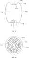
- FIG. 3is a bottom perspective view of an embodiment of a device for treatment of a patient's vasculature.
- FIG. 4is an elevation view of the device for treatment of a patient's vasculature of FIG. 3 .
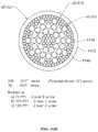
- FIG. 5is a transverse cross sectional view of the device of FIG. 4 taken along lines 5 - 5 in FIG. 4 .
- FIG. 6shows the device of FIG. 4 in longitudinal section taken along lines 6 - 6 in FIG. 4 .
- FIG. 7is an enlarged view of the woven filament structure taken from the encircled portion 7 shown in FIG. 5 .
- FIG. 8is an enlarged view of the woven filament structure taken from the encircled portion 8 shown in FIG. 6 .
- FIG. 9is a proximal end view of the device of FIG. 3 .
- FIG. 10is a transverse sectional view of a proximal hub portion of the device in FIG. 6 indicated by lines 10 - 10 in FIG. 6 .
- FIG. 11is an elevation view in partial section of a distal end of a delivery catheter with the device for treatment of a patient's vasculature of FIG. 3 disposed therein in a collapsed constrained state.
- FIG. 12is an elevation view of a distal portion of a delivery device or actuator showing some internal structure of the device.
- FIG. 13is an elevation view of the delivery device of FIG. 12 with the addition of some tubular elements over the internal structures.
- FIG. 14is an elevation view of the distal portion of the delivery device of FIG. 13 with an outer coil and marker in place.
- FIG. 15is an elevation view of a proximal portion of the delivery device.
- FIG. 16illustrates an embodiment of a filament configuration for a device for treatment of a patient's vasculature.
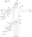
- FIG. 17is a schematic view of a patient being accessed by an introducer sheath, a microcatheter and a device for treatment of a patient's vasculature releasably secured to a distal end of a delivery device or actuator.
- FIG. 18is a sectional view of a terminal aneurysm.
- FIG. 19is a sectional view of an aneurysm.
- FIG. 20is a schematic view in section of an aneurysm showing perpendicular arrows which indicate interior nominal longitudinal and transverse dimensions of the aneurysm.
- FIG. 21is a schematic view in section of the aneurysm of FIG. 20 with a dashed outline of a device for treatment of a patient's vasculature in a relaxed unconstrained state that extends transversely outside of the walls of the aneurysm.
- FIG. 22is a schematic view in section of an outline of a device represented by the dashed line in FIG. 21 in a deployed and partially constrained state within the aneurysm.
- FIGS. 23-26show a deployment sequence of a device for treatment of a patient's vasculature.
- FIG. 27is an elevation view in partial section of an embodiment of a device for treatment of a patient's vasculature deployed within an aneurysm at a tilted angle.
- FIG. 28is an elevation view in partial section of an embodiment of a device for treatment of a patient's vasculature deployed within an irregularly shaped aneurysm.
- FIG. 29shows an elevation view in section of a device for treatment of a patient's vasculature deployed within a vascular defect aneurysm.
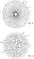
- FIG. 30shows a proximal perspective view of an embodiment of a device for treatment of a patient's vasculature with a sealing zone embodiment indicated by a set of dashed lines.
- FIGS. 31-35illustrate various different embodiments of braiding patterns that may be used for permeable shells of devices for treatment of a patient's vasculature.
- FIG. 36illustrates a device for treatment of a patient's vasculature that includes non-structural fibers in the permeable shell structure of the device.
- FIG. 37is an enlarged view of non-structural fibers woven into filaments of a permeable shell structure.
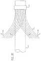
- FIG. 38is an elevation view of a mandrel used for manufacture of a braided tubular member for construction of an embodiment of a device for treatment of a patient's vasculature with the initiation of the braiding process shown.
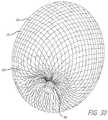
- FIG. 39is an elevation view of a braiding process for a braided tubular member used for manufacture of a device.
- FIG. 40is an elevation view in partial section of an embodiment of a fixture for heat setting a braided tubular member for manufacture of a device for treatment of a patient's vasculature.
- FIG. 41is an elevation view in partial section of an embodiment of a fixture for heat setting a braided tubular member for manufacture of a device for treatment of a patient's vasculature.
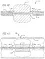
- FIG. 42is an elevation view in section of a device for treatment of a patient's vasculature.
- FIG. 43is a transverse sectional view of the device in FIG. 42 indicated by lines 7 - 7 in FIG. 42 .
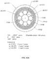
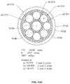
- FIGS. 43A-Eillustrate various embodiments of filament configurations for the device for treatment of a patient's vasculature.
- some device embodimentsmay be configured for collapse to a low profile constrained state with a transverse dimension suitable for delivery through an inner lumen of a microcatheter and deployment from a distal end thereof.
- Embodiments of these devicesmay also maintain a clinically effective configuration with sufficient mechanical integrity once deployed so as to withstand dynamic forces within a patient's vasculature over time that may otherwise result in compaction of a deployed device. It may also be desirable for some device embodiments to acutely occlude a vascular defect of a patient during the course of a procedure in order to provide more immediate feedback regarding success of the treatment to a treating physician.
- Some embodimentsare particularly useful for the treatment of cerebral aneurysms by reconstructing a vascular wall so as to wholly or partially isolate a vascular defect from a patient's blood flow.
- Some embodimentsmay be configured to be deployed within a vascular defect to facilitate reconstruction, bridging of a vessel wall or both in order to treat the vascular defect.
- the permeable shell of the devicemay be configured to anchor or fix the permeable shell in a clinically beneficial position.
- the devicemay be disposed in whole or in part within the vascular defect in order to anchor or fix the device with respect to the vascular structure or defect.
- the permeable shellmay be configured to span an opening, neck or other portion of a vascular defect in order to isolate the vascular defect, or a portion thereof, from the patient's nominal vascular system in order allow the defect to heal or to otherwise minimize the risk of the defect to the patient's health.
- the permeable shellmay be configured to allow some initial perfusion of blood through the permeable shell.
- the porosity of the permeable shellmay be configured to sufficiently isolate the vascular defect so as to promote healing and isolation of the defect, but allow sufficient initial flow through the permeable shell so as to reduce or otherwise minimize the mechanical force exerted on the membrane the dynamic flow of blood or other fluids within the vasculature against the device.
- a portion of the permeable shell that spans the opening or neck of the vascular defectneed be permeable and/or conducive to thrombus formation in a patient's bloodstream.
- that portion of the device that does not span an opening or neck of the vascular defectmay be substantially non-permeable or completely permeable with a pore or opening configuration that is too large to effectively promote thrombus formation.
- a hollow, thin walled devicewith a permeable shell of resilient material that may be constrained to a low profile for delivery within a patient.
- a devicemay also be configured to expand radially outward upon removal of the constraint such that the shell of the device assumes a larger volume and fills or otherwise occludes a vascular defect within which it is deployed.
- the outward radial expansion of the shellmay serve to engage some or all of an inner surface of the vascular defect whereby mechanical friction between an outer surface of the permeable shell of the device and the inside surface of the vascular defect effectively anchors the device within the vascular defect.
- Some embodiments of such a devicemay also be partially or wholly mechanically captured within a cavity of a vascular defect, particularly where the defect has a narrow neck portion with a larger interior volume.
- some device embodimentsinclude a matrix of woven or braided filaments that are coupled together by the interwoven structure so as to form a self-expanding permeable shell having a pore or opening pattern between couplings or intersections of the filaments that is substantially regularly spaced and stable, while still allowing for conformity and volumetric constraint.
- woven and braidedare used interchangeably to mean any form of interlacing of filaments to form a mesh structure.
- these termsmay have different or more specific meanings depending on the product or application such as whether an article is made in a sheet or cylindrical form. For purposes of the present disclosure, these terms are used interchangeably.
- three factorsmay be critical for a woven or braided wire occlusion device for treatment of a patient's vasculature that can achieve a desired clinical outcome in the endovascular treatment of cerebral aneurysms.
- the implant devicemay be desirable for the implant device to have sufficient radial stiffness for stability, limited pore size for near-complete acute (intra-procedural) occlusion and a collapsed profile which is small enough to allow insertion through an inner lumen of a microcatheter.
- a device with a radial stiffness below a certain thresholdmay be unstable and may be at higher risk of embolization in some cases.
- the radial stiffness, S radialmay be between about 0.014 and 0.284 lbf force for some embodiments of particular clinical value.
- the maximum pore size in a portion of a device that spans a neck or opening of a vascular defect desirable for some useful embodiments of a woven wire device for treatment of a patient's vasculaturemay be expressed as a function of the total number of all filaments, filament diameter and the device diameter. The difference between filament sizes where two or more filament diameters or transverse dimensions are used may be ignored in some cases for devices where the filament size(s) are very small compared to the device dimensions. For a two-filament device, the smallest filament diameter may be used for the calculation.
- Dis the Device diameter (transverse dimension)
- N Tis the total number of all filaments
- d wis the diameter of the filaments (smallest) in inches.
- the maximum pore size, P maxof a portion of a device that spans an opening of a vascular defect or neck, or any other suitable portion of a device, may be less than about 0.016 inches or about 400 microns for some embodiments. In some embodiments the maximum pore size for a defect spanning portion or any other suitable portion of a device may be less than about 0.012 inches or about 300 microns.
- N lis the number of large filaments
- N sis the number of small filaments
- d lis the diameter of the large filaments in inches
- d sis the diameter of the small filaments in inches.
- the collapsed profile P cmay be less than about 1.0 mm for some embodiments of particular clinical value.
- the devicemay be constructed so as to have all three factors (S radial , P max and P c ) above within the ranges discussed above; S radial between about 0.014 lbf and 0.284 lbf, P max less than about 300 microns and P c less than about 1.0 mm, simultaneously.
- the devicemay be made to include about 70 filaments to about 300 filaments.
- the filamentsmay have an outer transverse dimension or diameter of about 0.0004 inches to about 0.002 inches.
- some embodiments of devices for treatment of a patient's vasculaturecall for sizing the device which approximates (or with some over-sizing) the vascular site dimensions to fill the vascular site.
- scaling of a device to larger dimensions and using larger filamentswould suffice for such larger embodiments of a device.
- the diameter or profile of the radially collapsed deviceis limited by the catheter sizes that can be effectively navigated within the small, tortuous vessels of the brain.
- the pores or openings between junctions of the filamentsare correspondingly larger.
- flexural modulusmay be defined as the ratio of stress to strain.
- a devicemay be considered to have a high flexural modulus or be stiff if the strain (deflection) is low under a given force.
- a stiff devicemay also said to have low compliance.
- an outward radial force exerted by an outside surface of the filaments 14 of the device 10 against a constraining force when inserted into a vascular site such as blood vessel or aneurysmis lower for a given amount of device compression or over-sizing. This force may be important in some applications to assure device stability and to reduce the risk of migration of the device and potential distal embolization.
- a combination of small and large filament sizesmay be utilized to make a device with a desired radial compliance and yet have a collapsed profile which is configured to fit through an inner lumen of commonly used microcatheters.
- a device fabricated with even a small number of relatively large filaments 14can provide reduced radial compliance (or increased stiffness) compared to a device made with all small filaments.
- Even a relatively small number of larger filamentsmay provide a substantial increase in bending stiffness due to change in the moment of Inertia that results from an increase in diameter without increasing the total cross sectional area of the filaments.
- the stiffnesscan be increased by a significant amount without a large increase in the cross sectional area of a collapsed profile of the device 10 .
- Thismay be particularly important as device embodiments are made larger to treat large aneurysms. While large cerebral aneurysms may be relatively rare, they present an important therapeutic challenge as some embolic devices currently available to physicians have relatively poor results compared to smaller aneurysms.
- some embodiments of devices for treatment of a patient's vasculaturemay be formed using a combination of filaments 14 with a number of different diameters such as 2, 3, 4, 5 or more different diameters or transverse dimensions.
- some larger filament embodimentsmay have a transverse dimension of about 0.001 inches to about 0.004 inches and some small filament embodiments may have a transverse dimension or diameter of about 0.0004 inches and about 0.0015 inches, more specifically, about 0.0004 inches to about 0.001 inches.
- the ratio of the number of large filaments to the number of small filamentsmay be between about 2 and 12 and may also be between about 4 and 8.
- the difference in diameter or transverse dimension between the larger and smaller filamentsmay be less than about 0.004 inches, more specifically, less than about 0.0035 inches, and even more specifically, less than about 0.002 inches.
- device embodiments 10 for treatment of a patient's vasculaturemay include a plurality of wires, fibers, threads, tubes or other filamentary elements that form a structure that serves as a permeable shell.
- a globular shapemay be formed from such filaments by connecting or securing the ends of a tubular braided structure.
- the density of a braided or woven structuremay inherently increase at or near the ends where the wires or filaments 14 are brought together and decrease at or near a middle portion 30 disposed between a proximal end 32 and distal end 34 of the permeable shell 40 .
- an end or any other suitable portion of a permeable shell 40may be positioned in an opening or neck of a vascular defect such as an aneurysm for treatment.
- a braided or woven filamentary device with a permeable shellmay not require the addition of a separate defect spanning structure having properties different from that of a nominal portion of the permeable shell to achieve hemostasis and occlusion of the vascular defect.
- Such a filamentary devicemay be fabricated by braiding, weaving or other suitable filament fabrication techniques. Such device embodiments may be shape set into a variety of three dimensional shapes such as discussed herein.
- the device 10includes a self-expanding resilient permeable shell 40 having a proximal end 32 , a distal end 34 , a longitudinal axis 46 and further comprising a plurality of elongate resilient filaments 14 including large filaments 48 and small filaments 50 of at least two different transverse dimensions as shown in more detail in FIGS. 5,7 and 18 .
- the filaments 14have a woven structure and are secured relative to each other at proximal ends 60 and distal ends 62 thereof.
- the permeable shell 40 of the devicehas a radially constrained elongated state configured for delivery within a microcatheter 61 , as shown in FIG. 11 , with the thin woven filaments 14 extending longitudinally from the proximal end 42 to the distal end 44 radially adjacent each other along a length of the filaments.
- the permeable shell 40also has an expanded relaxed state with a globular and longitudinally shortened configuration relative to the radially constrained state.
- the woven filaments 14form the self-expanding resilient permeable shell 40 in a smooth path radially expanded from a longitudinal axis 46 of the device between the proximal end 32 and distal end 34 .
- the woven structure of the filaments 14includes a plurality of openings 64 in the permeable shell 40 formed between the woven filaments.
- the largest of said openings 64may be configured to allow blood flow through the openings only at a velocity below a thrombotic threshold velocity.
- Thrombotic threshold velocityhas been defined, at least by some, as the time-average velocity at which more than 50% of a vascular graft surface is covered by thrombus when deployed within a patient's vasculature.
- a slightly different thresholdmay be appropriate.
- the thrombotic threshold velocity as used hereinshall include the velocity at which clotting occurs within or on a device, such as device 10 , deployed within a patient's vasculature such that blood flow into a vascular defect treated by the device is substantially blocked in less than about 1 hour or otherwise during the treatment procedure.
- the blockage of blood flow into the vascular defectmay be indicated in some cases by minimal contrast agent entering the vascular defect after a sufficient amount of contrast agent has been injected into the patient's vasculature upstream of the implant site and visualized as it dissipates from that site.
- Such sustained blockage of flow within less than about 1 hour or during the duration of the implantation proceduremay also be referred to as acute occlusion of the vascular defect.
- any blood flowing through the permeable shellmay be slowed to a velocity below the thrombotic threshold velocity and thrombus will begin to form on and around the openings in the permeable shell 40 .
- this processmay be configured to produce acute occlusion of the vascular defect within which the device 10 is deployed.
- at least the distal end of the permeable shell 40may have a reverse bend in an everted configuration such that the secured distal ends 62 of the filaments 14 are withdrawn axially within the nominal permeable shell structure or contour in the expanded state.
- the proximal end of the permeable shellfurther includes a reverse bend in an everted configuration such that the secured proximal ends 60 of the filaments 14 are withdrawn axially within the nominal permeable shell structure 40 in the expanded state.
- evertedmay include a structure that is everted, partially everted and/or recessed with a reverse bend as shown in the device embodiment of FIGS. 3-6 .
- the ends 60 and 62 of the filaments 14 of the permeable shell or hub structure disposed around the endsmay be withdrawn within or below the globular shaped periphery of the permeable shell of the device.
- the elongate resilient filaments 14 of the permeable shell 40may be secured relative to each other at proximal ends 60 and distal ends 62 thereof by one or more methods including welding, soldering, adhesive bonding, epoxy bonding or the like.
- a distal hub 66may also be secured to the distal ends 62 of the thin filaments 14 of the permeable shell 40 and a proximal hub 68 secured to the proximal ends 60 of the thin filaments 14 of the permeable shell 40 .
- the proximal hub 68may include a cylindrical member that extends proximally beyond the proximal ends 60 of the thin filaments so as to form a cavity 70 within a proximal portion of the proximal hub 68 .
- the proximal cavity 70may be used for holding adhesives such as epoxy, solder or any other suitable bonding agent for securing an elongate detachment tether 72 that may in turn be detachably secured to a delivery apparatus such as is shown in FIGS. 11-15 .
- the elongate resilient filaments 14 of the permeable shell 40may have a transverse cross section that is substantially round in shape and be made from a superelastic material that may also be a shape memory metal.
- the shape memory metal of the filaments of the permeable shell 40may be heat set in the globular configuration of the relaxed expanded state as shown in FIGS. 3-6 .
- Suitable superelastic shape memory metalsmay include alloys such as NiTi alloy and the like.
- the superelastic properties of such alloysmay be useful in providing the resilient properties to the elongate filaments 14 so that they can be heat set in the globular form shown, fully constrained for delivery within an inner lumen of a microcatheter and then released to self expand back to substantially the original heat set shape of the globular configuration upon deployment within a patient's body.
- the device 10may have an everted filamentary structure with a permeable shell 40 having a proximal end 32 and a distal end 34 in an expanded relaxed state.
- the permeable shell 40has a substantially enclosed configuration for the embodiments shown. Some or all of the permeable shell 40 of the device 10 may be configured to substantially block or impede fluid flow or pressure into a vascular defect or otherwise isolate the vascular defect over some period of time after the device is deployed in an expanded state.
- the permeable shell 40 and device 10generally also has a low profile, radially constrained state, as shown in FIG. 11 , with an elongated tubular or cylindrical configuration that includes the proximal end 32 , the distal end 34 and a longitudinal axis 46 .
- the elongate flexible filaments 14 of the permeable shell 40may be disposed substantially parallel and in close lateral proximity to each other between the proximal end and distal end forming a substantially tubular or compressed cylindrical configuration.
- Proximal ends 60 of at least some of the filaments 14 of the permeable shell 40may be secured to the proximal hub 68 and distal ends 62 of at least some of the filaments 14 of the permeable shell 40 are secured to the distal hub 66 , with the proximal hub 68 and distal hub 66 being disposed substantially concentric to the longitudinal axis 46 as shown in FIG. 4 .
- the ends of the filaments 14may be secured to the respective hubs 66 and 68 by any of the methods discussed above with respect to securement of the filament ends to each other, including the use of adhesives, solder, welding and the like.
- a middle portion 30 of the permeable shell 40may have a first transverse dimension with a low profile suitable for delivery from a microcatheter as shown in FIG. 11 .
- Radial constraint on the device 10may be applied by an inside surface of the inner lumen of a microcatheter, such as the distal end portion of the microcatheter 61 shown, or it may be applied by any other suitable mechanism that may be released in a controllable manner upon ejection of the device 10 from the distal end of the catheter.
- a proximal end or hub 68 of the device 10is secured to a distal end of an elongate delivery apparatus 110 of a delivery system 112 disposed at the proximal hub 68 of the device 10 .
- Some device embodiments 10 having a braided or woven filamentary structuremay be formed using about 10 filaments to about 300 filaments 14 , more specifically, about 10 filaments to about 100 filaments 14 , and even more specifically, about 60 filaments to about 80 filaments 14 .
- Some embodiments of a permeable shell 40may include about 70 filaments to about 300 filaments extending from the proximal end 32 to the distal end 34 , more specifically, about 100 filaments to about 200 filaments extending from the proximal end 32 to the distal end 34 .
- the filaments 14may have a transverse dimension or diameter of about 0.0008 inches to about 0.004 inches.
- the elongate resilient filaments 14in some cases may have an outer transverse dimension or diameter of about 0.0005 inch to about 0.005 inch, more specifically, about 0.001 inch to about 0.003 inch, and in some cases about 0.0004 inches to about 0.002 inches.
- the large filaments 48 of the permeable shell 40may have a transverse dimension or diameter that is about 0.001 inches to about 0.004 inches and the small filaments 50 may have a transverse dimension or diameter of about 0.0004 inches to about 0.0015 inches, more specifically, about 0.0004 inches to about 0.001 inches.
- a difference in transverse dimension or diameter between the small filaments 50 and the large filaments 48may be less than about 0.004 inches, more specifically, less than about 0.0035 inches, and even more specifically, less than about 0.002 inches.
- the number of small filaments 50 of the permeable shell 40 relative to the number of large filaments 48 of the permeable shell 40may be about 2 to 1 to about 15 to 1, more specifically, about 2 to 1 to about 12 to 1, and even more specifically, about 4 to 1 to about 8 to 1.
- the expanded relaxed state of the permeable shell 40has an axially shortened configuration relative to the constrained state such that the proximal hub 68 is disposed closer to the distal hub 66 than in the constrained state.
- Both hubs 66 and 68are disposed substantially concentric to the longitudinal axis 46 of the device and each filamentary element 14 forms a smooth arc between the proximal and distal hubs 66 and 68 with a reverse bend at each end.
- a longitudinal spacing between the proximal and distal hubs 66 and 68 of the permeable shell 40 in a deployed relaxed statemay be about 25 percent to about 75 percent of the longitudinal spacing between the proximal and distal hubs 66 and 68 in the constrained cylindrical state, for some embodiments.
- the arc of the filaments 14 between the proximal and distal ends 32 and 34may be configured such that a middle portion of each filament 14 has a second transverse dimension substantially greater than the first transverse dimension.
- the permeable shell 40may have a first transverse dimension in a collapsed radially constrained state of about 0.2 mm to about 2 mm and a second transverse dimension in a relaxed expanded state of about 4 mm to about 30 mm.
- the second transverse dimension of the permeable shell 40 in an expanded statemay be about 2 times to about 150 times the first transverse dimension, more specifically, about 10 times to about 25 times the first or constrained transverse dimension.
- a longitudinal spacing between the proximal end 32 and distal end 34 of the permeable shell 40 in the relaxed expanded statemay be about 25% percent to about 75% percent of the spacing between the proximal end 32 and distal end 34 in the constrained cylindrical state.
- a major transverse dimension of the permeable shell 40 in a relaxed expanded statemay be about 4 mm to about 30 mm, more specifically, about 9 mm to about 15 mm, and even more specifically, about 4 mm to about 8 mm.
- An arced portion of the filaments 14 of the permeable shell 40may have a sinusoidal-like shape with a first or outer radius 88 and a second or inner radius 90 near the ends of the permeable shell 40 as shown in FIG. 6 .
- This sinusoid-like or multiple curve shapemay provide a concavity in the proximal end 32 that may reduce an obstruction of flow in a parent vessel adjacent a vascular defect.
- the first radius 88 and second radius 90 of the permeable shell 40may be between about 0.12 mm to about 3 mm.
- the distance between the proximal end 32 and distal end 34may be less than about 60% of the overall length of the permeable shell 40 for some embodiments.
- each filament 14may have a substantially continuous curvature. This substantially continuous curvature may provide smooth deployment and may reduce the risk of vessel perforation.
- one of the ends 32 or 34may be retracted or everted to a greater extent than the other so as to be more longitudinally or axially conformal than the other end.
- the first radius 88 and second radius 90 of the permeable shell 40may be between about 0.12 mm to about 3 mm for some embodiments.
- the distance between the proximal end 32 and distal end 34may be more than about 60% of the overall length of the expanded permeable shell 40 .
- the largest longitudinal distance between the inner surfacesmay be about 60% to about 90% of the longitudinal length of the outer surfaces or the overall length of device 10 .
- a gap between the hubs 66 and 68 at the proximal end 32 and distal end 34may allow for the distal hub 66 to flex downward toward the proximal hub 68 when the device 10 meets resistance at the distal end and thus provides longitudinal conformance.
- the filaments 14may be shaped such that there are no portions that are without curvature over a distance of more than about 2 mm. Thus, for some embodiments, each filament 14 may have a substantially continuous curvature. This substantially continuous curvature may provide smooth deployment and may reduce the risk of vessel perforation.
- the distal end 34may be retracted or everted to a greater extent than the proximal end 32 such that the distal end portion of the permeable shell 40 may be more radially conformal than the proximal end portion. Conformability of a distal end portion may provide better device conformance to irregular shaped aneurysms or other vascular defects.
- a convex surface of the devicemay flex inward forming a concave surface to conform to curvature of a vascular site.
- FIG. 10shows an enlarged view of the filaments 14 disposed within a proximal hub 68 of the device 10 with the filaments 14 of two different sizes constrained and tightly packed by an outer ring of the proximal hub 68 .
- the tether member 72may optionally be disposed within a middle portion of the filaments 14 or within the cavity 70 of the proximal hub 68 proximal of the proximal ends 60 of the filaments 14 as shown in FIG. 6 .
- the distal end of the tether 72may be secured with a knot 92 formed in the distal end thereof which is mechanically captured in the cavity 70 of the proximal hub 68 formed by a proximal shoulder portion 94 of the proximal hub 68 .
- the knotted distal end 92 of the tether 72may also be secured by bonding or potting of the distal end of the tether 72 within the cavity 70 and optionally amongst the proximal ends 60 of the filaments 14 with mechanical compression, adhesive bonding, welding, soldering, brazing or the like.
- the tether embodiment 72 shown in FIG. 6has a knotted distal end 92 potted in the cavity of the proximal hub 68 with an adhesive.
- Such a tether 72may be a dissolvable, severable or releasable tether that may be part of a delivery apparatus 110 used to deploy the device 10 as shown in FIG. 11 and FIGS. 23-26 .
- FIG. 10also shows the large filaments 48 and small filaments 50 disposed within and constrained by the proximal hub 68 which may be configured to secure the large and small filaments 48 and 50 in place relative to each other within the outer ring of the proximal hub 68 .
- FIGS. 7 and 8illustrate some configuration embodiments of braided filaments 14 of a permeable shell 40 of the device 10 for treatment of a patient's vasculature.
- the braid structure in each embodimentis shown with a circular shape 100 disposed within a pore 64 of a woven or braided structure with the circular shape 100 making contact with each adjacent filament segment.
- the pore opening sizemay be determined at least in part by the size of the filament elements 14 of the braid, the angle overlapping filaments make relative to each other and the picks per inch of the braid structure.
- the cells or openings 64may have an elongated substantially diamond shape as shown in FIG.
- the pores or openings 64 of the permeable shell 40may have a substantially more square shape toward a middle portion 30 of the device 10 , as shown in FIG. 8 .
- the diamond shaped pores or openings 64may have a length substantially greater than the width particularly near the hubs 66 and 68 .
- the ratio of diamond shaped pore or opening length to widthmay exceed a ratio of 3 to 1 for some cells.
- the diamond-shaped openings 64may have lengths greater than the width thus having an aspect ratio, defined as Length/Width of greater than 1.
- the openings 64 near the hubs 66 and 68may have substantially larger aspect ratios than those farther from the hubs as shown in FIG. 7 .
- the aspect ratio of openings 64 adjacent the hubsmay be greater than about 4 to 1.
- the aspect ratio of openings 64 near the largest diametermay be between about 0.75 to 1 and about 2 to 1 for some embodiments.
- the aspect ratio of the openings 64 in the permeable shell 40may be about 0.5 to 1 to about 2 to 1.
- the pore size defined by the largest circular shapes 100 that may be disposed within openings 64 of the braided structure of the permeable shell 40 without displacing or distorting the filaments 14 surrounding the opening 64may range in size from about 0.005 inches to about 0.01 inches, more specifically, about 0.006 inches to about 0.009 inches, even more specifically, about 0.007 inches to about 0.008 inches for some embodiments.
- at least some of the openings 64 formed between adjacent filaments 14 of the permeable shell 40 of the device 10may be configured to allow blood flow through the openings 64 only at a velocity below a thrombotic threshold velocity.
- the largest openings 64 in the permeable shell structure 40may be configured to allow blood flow through the openings 64 only at a velocity below a thrombotic threshold velocity.
- the pore sizemay be less than about 0.016 inches, more specifically, less than about 0.012 inches for some embodiments.
- the openings 64 formed between adjacent filaments 14may be about 0.005 inches to about 0.04 inches.
- the apparatus 110includes an elongate core wire 114 that extends from a proximal end 116 of the apparatus 110 to a distal section 118 of the apparatus 110 as shown in FIG. 12 .
- the core wire 114is configured to provide sufficient column strength to push a constrained device 10 for treatment of a patient's vasculature through an inner lumen 120 of the microcatheter 61 of the delivery system 112 as shown in FIG. 11 .
- the core wire 114also has sufficient tensile strength to withdraw or proximally retract the device 10 from a position outside the microcatheter 61 and axially within the inner lumen 120 of the microcatheter 61 .
- the tether 72 that extends proximally from the proximal hub 68is secured to the distal end of the core wire 114 with a length of shrinkable tubing 122 that is disposed over a portion of the tether 72 and a distal section of the core wire 114 and shrunk over both as shown in FIG. 13 , although any other suitable means of securement may be used.
- a heater coil 124 electrically coupled to a first conductor 126 and a second conductor 128is disposed over a distal most portion of the tether 72 .
- the heater coil 124may also be covered with a length of polymer tubing 130 disposed over the heater coil 124 distal of the heat shrink tubing 122 that serves to act as a heat shield and minimizes the leakage of heat from the heater coil 124 into the environment, such as the patient's blood stream, around the delivery apparatus 110 .
- An over coil 132 that extends from a distal end 134 of the delivery apparatus 110 to a proximal section 136 of the apparatus 110may then be disposed over the heater coil 124 , core wire 114 , tether 72 , first conductor 126 and second conductor 128 to hold these elements together, produce a low friction outer surface and maintain a desired flexibility of the delivery apparatus 110 .
- the proximal section 136 of the apparatus 110includes the proximal terminus of the over coil 132 which is disposed distal of a first contact 138 and second contact 140 which are circumferentially disposed about the proximal section 136 of the core wire 114 , insulated therefrom, and electrically coupled to the first conductor 126 and second conductor 128 , respectively as shown in FIG. 15 .
- the heater coil 124may be configured to receive electric current supplied through the first conductor 126 and second conductor 128 from an electrical energy source 142 coupled to the first contact 138 and second contact 140 at the proximal section 136 of the apparatus 110 .
- the electrical current passed through the heater coil 124heats the heater coil to a temperature above the melting point of the tether material 72 so as to melt the tether 72 and sever it upon deployment of the device 10 .
- Embodiments of the delivery apparatus 110may generally have a length greater than the overall length of a microcatheter 61 to be used for the delivery system 112 . This relationship allows the delivery apparatus 110 to extend, along with the device 10 secured to the distal end thereof, from the distal port of the inner lumen 120 of the microcatheter 61 while having sufficient length extending from a proximal end 150 of the microcatheter 61 , shown in FIG. 17 discussed below, to enable manipulation thereof by a physician.
- the length of the delivery apparatus 110may be about 170 cm to about 200 cm.
- the core wire 114may be made from any suitable high strength material such as stainless steel, NiTi alloy, or the like.
- Embodiments of the core wire 114may have an outer diameter or transverse dimension of about 0.010 inch to about 0.015 inch.
- the over coil 132may have an outer diameter or transverse dimension of about 0.018 inch to about 0.03 inch.
- the apparatus embodiment 110 shown in FIGS. 12-15is activated by electrical energy passed through a conductor pair, a similar configuration that utilizes light energy passed through a fiber optic or any other suitable arrangement could be used to remotely heat a distal heating member or element such as the heater coil 124 to sever the distal portion of the tether 72 .
- other delivery apparatus embodimentsare discussed and incorporated herein that may also be used for any of the device embodiments 10 for treatment of a patient's vasculature discussed herein.
- the delivery and positioning apparatusmay include a distal rotating member that allows rotational positioning of the device.
- the delivery and positioning apparatusmay include a distal rotating member which rotates an implant in-vivo without the transmission of torque along the entire length of the apparatus.
- delivery systemmay also rotate the implant without the transmission of torque in the intermediate portion between the proximal end and the distal rotatable end.
- the delivery and positioning apparatusmay be releasably secured to any suitable portion of the device for treatment of a patient's vasculature.
- Device embodiments discussed hereinmay be releasable from any suitable flexible, elongate delivery apparatus or actuator such as a guidewire or guidewire-like structure.
- the release of device embodiments from such a delivery apparatusmay be activated by a thermal mechanism, as discussed above, electrolytic mechanism, hydraulic mechanism, shape memory material mechanism, or any other mechanism known in the art of endovascular implant deployment.
- Embodiments for deployment and release of therapeutic devicesmay include connecting such a device via a releasable connection to a distal portion of a pusher or other delivery apparatus member.
- the therapeutic device 10may be detachably mounted to the distal portion of the apparatus by a filamentary tether 72 , string, thread, wire, suture, fiber, or the like, which may be referred to above as the tether.
- the tether 72may be in the form of a monofilament, rod, ribbon, hollow tube, or the like. Some embodiments of the tether may have a diameter or maximum thickness of between about 0.05 mm and 0.2 mm.
- the tether 72may be configured to be able to withstand a maximum tensile load of between about 0.5 kg and 5 kg.
- some known detachment devicesmay lack sufficient tensile strength to be used for some embodiments discussed herein. As such, it may be desirable to use small very high strength fibers for some tether embodiments having a “load at break” greater than about 15 Newtons.
- a tether made from a material known as Dyneema Purity available from Royal DSM, Heerlen, Netherlandsmay be used.
- the tether 72may be severed by the input of energy such as electric current to a heating element causing release of the therapeutic device.
- the heating elementmay be a coil of wire with high electrical resistivity such as a platinum-tungsten alloy.
- the tether membermay pass through or be positioned adjacent the heater element.
- the heatermay be contained substantially within the distal portion of the delivery apparatus to provide thermal insulation to reduce the potential for thermal damage to the surrounding tissues during detachment.
- currentmay pass through the tether which also acts as a heating element.
- tether embodiments 72including polymers, metals and composites thereof.
- One class of materials that may be useful for tethersincludes polymers such as polyolefin, polyolefin elastomer such as polyethylene, polyester (PET), polyamide (Nylon), polyurethane, polypropylene, block copolymer such as PEBAX or Hytrel, and ethylene vinyl alcohol (EVA); or rubbery materials such as silicone, latex, and Kraton.
- the polymermay also be cross-linked with radiation to manipulate its tensile strength and melt temperature.
- Another class of materials that may be used for tether embodimentmay include metals such as nickel titanium alloy (Nitinol), gold, platinum, tantalum and steel.
- LCPliquid crystal polymers
- Vectranwhich is produced by Kuraray Co. (Tokyo, Japan). The selection of the material may depend on the melting or softening temperature, the power used for detachment, and the body treatment site.
- the tethermay be joined to the implant and/or the pusher by crimping, welding, knot tying, soldering, adhesive bonding, or other means known in the art.
- FIG. 16shows an enlarged view in transverse cross section of a proximal hub configuration.
- the filaments 14are disposed within a proximal hub 68 or end portion of the device 10 with the filaments 14 constrained and tightly packed by an outer ring of the proximal hub 68 .
- a tether member 72may be disposed within a middle portion of the filaments 14 or within a cavity of the proximal hub 68 proximal of the proximal ends 60 of the filaments 14 .
- Such a tether 72may be a dissolvable, severable or releasable tether that may be part of a release apparatus as discussed above used to deploy the device.
- FIG. 16illustrates in transverse cross section an embodiment of a proximal hub 68 showing the configuration of filaments which may be tightly packed and radially constrained by an inside surface of the proximal hub 68 .
- the braided or woven structure of the permeable shell 40 formed from such filaments 14may be constructed using a large number of small filaments.
- the number of filaments 14may be greater than 125 and may also be between about 80 filaments and about 180 filaments.
- the total number of filaments 14for some embodiments may be about 70 filaments to about 300 filaments, more specifically, about 100 filaments to about 200 filaments.
- the braided structure of the permeable shell 40may be constructed with two or more sizes of filaments 14 .
- the structuremay have several larger filaments that provide structural support and several smaller filaments that provide the desired pore size and density and thus flow resistance to achieve a thrombotic threshold velocity in some cases.
- small filaments 50 of the permeable shell 40may have a transverse dimension or diameter of about 0.0006 inches to about 0.002 inches for some embodiments and about 0.0004 inches to about 0.001 inches in other embodiments.
- the large filaments 48may have a transverse dimension or diameter of about 0.0015 inches to about 0.004 inches in some embodiments and about 0.001 inches to about 0.004 inches in other embodiments.
- the filaments 14may be braided in a plain weave that is one under, one over structure (shown in FIGS. 7 and 8 ) or a supplementary weave; more than one warp interlace with one or more than one weft.
- the pick countmay be varied between about 25 and 200 picks per inch (PPI).
- the permeable shell 40 or portions thereofmay be porous and may be highly permeable to liquids.
- the permeable shell 40 of some embodiments discussed hereinmay have a water permeability greater than about 2,000 mI/min/cm 2 , in some cases greater than about 2,500 ml/min/cm 2 .
- water permeability of the permeable shell 40 or portions thereofmay be between about 2,000 and 10,000 ml/min/cm 2 , more specifically, about 2,000 ml/min/cm 2 to about 15,000 mI/min/cm 2 , when measured at a pressure of 120 mmHg.
- Device embodiments and components thereofmay include metals, polymers, biologic materials and composites thereof.
- Suitable metalsinclude zirconium-based alloys, cobalt-chrome alloys, nickel-titanium alloys, platinum, tantalum, stainless steel, titanium, gold, and tungsten.
- Potentially suitable polymersinclude but are not limited to acrylics, silk, silicones, polyvinyl alcohol, polypropylene, polyvinyl alcohol, polyesters (e.g. polyethylene terephthalate or PET), PolyEtherEther Ketone (PEEK), polytetrafluoroethylene (PTFE), polycarbonate urethane (PCU) and polyurethane (PU).
- Device embodimentsmay include a material that degrades or is absorbed or eroded by the body.
- a bioresorbablee.g., breaks down and is absorbed by a cell, tissue, or other mechanism within the body
- bioabsorbablesimilar to bioresorbable
- a bioerodablee.g., erodes or degrades over time by contact with surrounding tissue fluids, through cellular activity or other physiological degradation mechanisms
- biodegradablee.g., degrades over time by enzymatic or hydrolytic action, or other mechanism in the body
- dissolvable materialmay be employed. Each of these terms is interpreted to be interchangeable.
- bioabsorbable polymere.g., breaks down and is absorbed by a cell, tissue, or other mechanism within the body
- a bioabsorbablee.g., erodes or degrades over time by contact with surrounding tissue fluids, through cellular activity or other physiological degradation mechanisms
- biodegradablee.g., degrades
- bioabsorbable materialsinclude polylactic acid (PLA), poly(alpha-hydroxy acid) such as poly-L-lactide (PLLA), poly-D-lactide (PDLA), polyglycolide (PGA), polydioxanone, polycaprolactone, polygluconate, polylactic acid-polyethylene oxide copolymers, modified cellulose, collagen, poly(hydroxybutyrate), polyanhydride, polyphosphoester, poly(amino acids), or related copolymer materials.
- PLApolylactic acid
- PLLApoly(alpha-hydroxy acid)
- PLLApoly-L-lactide
- PDLApoly-D-lactide
- PGApolyglycolide
- polydioxanonepolycaprolactone
- polygluconatepolylactic acid-polyethylene oxide copolymers
- modified cellulosecollagen, poly(hydroxybutyrate), polyanhydride, polyphosphoester, poly(amino acids), or related copolymer materials.
- An absorbable composite fibermay be made by combining a reinforcement fiber made from a copolymer of about 18% glycolic acid and about 82% lactic acid with a matrix material consisting of a blend of the above copolymer with about 20% polycaprolactone (PCL).
- PCLpolycaprolactone
- the permeable shell structure 40may include one or more fixation elements or surfaces to facilitate fixation of the device within a blood vessel or other vascular site.
- the fixation elementsmay comprise hooks, barbs, protrusions, pores, microfeatures, texturing, bioadhesives or combinations thereof.
- Embodiments of the support structuremay be fabricated from a tube of metal where portions are removed. The removal of material may be done by laser, electrical discharge machining (EDM), photochemical etching and traditional machining techniques.
- the support structuremay be constructed with a plurality of wires, cut or etched from a sheet of a material, cut or etched from a tube or a combination thereof as in the art of vascular stent fabrication.
- Permeable shell embodiments 40may be formed at least in part of wire, ribbon, or other filamentary elements 14 . These filamentary elements 14 may have circular, elliptical, ovoid, square, rectangular, or triangular cross-sections. Permeable shell embodiments 40 may also be formed using conventional machining, laser cutting, electrical discharge machining (EDM) or photochemical machining (PCM). If made of a metal, it may be formed from either metallic tubes or sheet material.
- EDMelectrical discharge machining
- PCMphotochemical machining
- Device embodiments 10 discussed hereinmay be delivered and deployed from a delivery and positioning system 112 that includes a microcatheter 61 , such as the type of microcatheter 61 that is known in the art of neurovascular navigation and therapy.
- Device embodiments for treatment of a patient's vasculature 10may be elastically collapsed and restrained by a tube or other radial restraint, such as an inner lumen 120 of a microcatheter 61 , for delivery and deployment.
- the microcatheter 61may generally be inserted through a small incision 152 accessing a peripheral blood vessel such as the femoral artery or brachial artery.
- the microcatheter 61may be delivered or otherwise navigated to a desired treatment site 154 from a position outside the patient's body 156 over a guidewire 159 under fluoroscopy or by other suitable guiding methods.
- the guidewire 159may be removed during such a procedure to allow insertion of the device 10 secured to a delivery apparatus 110 of the delivery system 112 through the inner lumen 120 of a microcatheter 61 in some cases.
- FIG. 17illustrates a schematic view of a patient 158 undergoing treatment of a vascular defect 160 as shown in FIG. 18 .
- An access sheath 162is shown disposed within either a radial artery 164 or femoral artery 166 of the patient 158 with a delivery system 112 that includes a microcatheter 61 and delivery apparatus 110 disposed within the access sheath 162 .
- the delivery system 112is shown extending distally into the vasculature of the patient's brain adjacent a vascular defect 160 in the patient's brain.
- Access to a variety of blood vessels of a patientmay be established, including arteries such as the femoral artery 166 , radial artery 164 , and the like in order to achieve percutaneous access to a vascular defect 160 .
- the patient 158may be prepared for surgery and the access artery is exposed via a small surgical incision 152 and access to the lumen is gained using the Seldinger technique where an introducing needle is used to place a wire over which a dilator or series of dilators dilates a vessel allowing an introducer sheath 162 to be inserted into the vessel. This would allow the device to be used percutaneously.
- a guiding catheter 168is then used to provide a safe passageway from the entry site to a region near the target site 154 to be treated.
- a guiding catheter 168would be chosen which would extend from the entry site 152 at the femoral artery up through the large arteries extending around the heart through the aortic arch, and downstream through one of the arteries extending from the upper side of the aorta such as the carotid artery 170 .
- a guidewire 159 and neurovascular microcatheter 61are then placed through the guiding catheter 168 and advanced through the patient's vasculature, until a distal end 151 of the microcatheter 61 is disposed adjacent or within the target vascular defect 160 , such as an aneurysm.
- exemplary guidewires 159 for neurovascular useinclude the Synchro2® made by Boston Scientific and the Glidewire Gold Neuro® made by MicroVention Terumo. Typical guidewire sizes may include 0.014 inches and 0.018 inches.
- Delivery and deployment of device embodiments 10 discussed hereinmay be carried out by first compressing the device 10 to a radially constrained and longitudinally flexible state as shown in FIG. 11 .
- the device 10may then be delivered to a desired treatment site 154 while disposed within the microcatheter 61 , and then ejected or otherwise deployed from a distal end 151 of the microcatheter 61 .
- the microcatheter 61may first be navigated to a desired treatment site 154 over a guidewire 159 or by other suitable navigation techniques.
- the distal end of the microcatheter 61may be positioned such that a distal port of the microcatheter 61 is directed towards or disposed within a vascular defect 160 to be treated and the guidewire 159 withdrawn.
- the device 10 secured to a suitable delivery apparatus 110may then be radially constrained, inserted into a proximal portion of the inner lumen 120 of the microcatheter 61 and distally advanced to the vascular defect 160 through the inner lumen 120 .
- the device 10may then allowed to assume an expanded relaxed or partially relaxed state with the permeable shell 40 of the device spanning or partially spanning a portion of the vascular defect 160 or the entire vascular defect 160 .
- the device 10may also be activated by the application of an energy source to assume an expanded deployed configuration once ejected from the distal section of the microcatheter 61 for some embodiments. Once the device 10 is deployed at a desired treatment site 154 , the microcatheter 61 may then be withdrawn.
- Some embodiments of devices for the treatment of a patient's vasculature 10 discussed hereinmay be directed to the treatment of specific types of defects of a patient's vasculature.
- an aneurysm 160commonly referred to as a terminal aneurysm is shown in section. Terminal aneurysms occur typically at bifurcations in a patient's vasculature where blood flow, indicated by the arrows 172 , from a supply vessel splits into two or more branch vessels directed away from each other.
- the main flow of blood from the supply vessel 174such as a basilar artery, sometimes impinges on the vessel where the vessel diverges and where the aneurysm sack forms.
- Terminal aneurysmsmay have a well defined neck structure where the profile of the aneurysm 160 narrows adjacent the nominal vessel profile, but other terminal aneurysm embodiments may have a less defined neck structure or no neck structure.
- FIG. 19illustrates a typical berry type aneurysm 160 in section where a portion of a wall of a nominal vessel section weakens and expands into a sack like structure ballooning away from the nominal vessel surface and profile.
- Some berry type aneurysmsmay have a well defined neck structure as shown in FIG. 19 , but others may have a less defined neck structure or none at all.
- FIG. 19illustrates a typical berry type aneurysm 160 in section where a portion of a wall of a nominal vessel section weakens and expands into a sack like structure ballooning away from the nominal vessel surface and profile.
- Some berry type aneurysmsmay have a well defined neck structure as shown in FIG. 19 , but others may have a less defined
- FIG. 19also shows some optional procedures wherein a stent 173 or other type of support has been deployed in the parent vessel 174 adjacent the aneurysm. Also, shown is embolic material 176 being deposited into the aneurysm 160 through a microcatheter 61 . Either or both of the stent 173 and embolic material 176 may be so deployed either before or after the deployment of a device for treatment of a patient's vasculature 10 .
- Some embodiments of treatmentmay include estimating a volume of a vascular site or defect 160 to be treated and selecting a device 10 with a volume that is substantially the same volume or slightly over-sized relative to the volume of the vascular site or defect 160 .
- the volume of the vascular defect 160 to be occludedmay be determined using three-dimensional angiography or other similar imaging techniques along with software which calculates the volume of a selected region.
- the amount of over-sizingmay be between about 2% and 15% of the measured volume.
- a device 10 deployed within such an irregularly shaped aneurysm 160is shown in FIG. 28 discussed below.
- Such a method embodimentmay also include implanting or deploying the device 10 so that the vascular defect 160 is substantially filled volumetrically by a combination of device and blood contained therein.
- the device 10may be configured to be sufficiently conformal to adapt to irregular shaped vascular defects 160 so that at least about 75%, in some cases about 80%, of the vascular defect volume is occluded by a combination of device 10 and blood contained therein.
- FIGS. 20-22illustrate a schematic representation of how a device 10 may be chosen for a proper fit after deployment that is initially oversized in a transverse dimension by at least about 10% of the largest transverse dimension of the vascular defect 160 and sometimes up to about 100% of the largest transverse dimension.
- the device 10may be oversized a small amount (e.g. less than about 1.5 mm) in relation to measured dimensions for the width, height or neck diameter of the vascular defect 160 .
- a vascular defect 160 in the form of a cerebral aneurysmis shown with horizontal arrows 180 and vertical arrows 182 indicating the approximate largest interior dimensions of the defect 160 .
- Arrow 180 extending horizontallyindicates the largest transverse dimension of the defect 160 .
- a dashed outline 184 of a device for treatment of the vascular defect 10is shown superimposed over the vascular defect 160 of FIG. 20 illustrating how a device 10 that has been chosen to be approximately 20% oversized in a transverse dimension would look in its unconstrained, relaxed state.
- FIG. 22illustrates how the device 10 which is indicated by the dashed line 184 of FIG.
- the device 10might conform to the interior surface of the vascular defect 160 after deployment whereby the nominal transverse dimension of the device 10 in a relaxed unconstrained state has now been slightly constrained by the inward radial force 185 exerted by the vascular defect 160 on the device 10 .
- the device 10has assumed a slightly elongated shape in the axial or longitudinal axis of the device 10 so as to elongate and better fill the interior volume of the defect 160 as indicated by the downward arrow 186 in FIG. 22 .
- the delivery and deployment processmay then proceed.
- the properties of the device embodiments 10 and delivery system embodiments 112 discussed hereingenerally allow for retraction of a device 10 after initial deployment into a defect 160 , but before detachment of the device 10 . Therefore, it may also be possible and desirable to withdraw or retrieve an initially deployed device 10 after the fit within the defect 160 has been evaluated in favor of a differently sized device 10 .
- An example of a terminal aneurysm 160is shown in FIG. 23 in section.
- the tip 151 of a catheter, such as a microcatheter 61may be advanced into or adjacent the vascular site or defect 160 (e.g. aneurysm) as shown in FIG. 24 .
- an embolic coil or other vaso-occlusive device or material 176may optionally be placed within the aneurysm 160 to provide a framework for receiving the device 10 .
- a stent 173may be placed within a parent vessel 174 of some aneurysms substantially crossing the aneurysm neck prior to or during delivery of devices for treatment of a patient's vasculature discussed herein (also as shown for example in FIG. 19 ).
- An example of a suitable microcatheter 61 having an inner lumen diameter of about 0.020 inches to about 0.022 inchesis the Rapid Transit® manufactured by Cordis Corporation.
- microcatheters 61may include microcatheters having an inner lumen diameter of about 0.026 inch to about 0.028 inch, such as the Rebar® by Ev3 Company, the Renegade Hi-Flow® by Boston Scientific Corporation, and the Mass Transit® by Cordis Corporation.
- Suitable microcatheters having an inner lumen diameter of about 0.031 inch to about 0.033 inchmay include the Marksmen® by Chestnut Medical Technologies, Inc. and the Vasco 28® by Bait Extrusion.
- a suitable microcatheter 61 having an inner lumen diameter of about 0.039 inch to about 0.041 inchincludes the Vasco 35 by Bait Extrusion.
- These microcatheters 61are listed as exemplary embodiments only, other suitable microcatheters may also be used with any of the embodiments discussed herein.
- Detachment of the device 10 from the delivery apparatus 110may be controlled by a control switch 188 disposed at a proximal end of the delivery system 112 , which may also be coupled to an energy source 142 , which severs the tether 72 that secures the proximal hub 68 of the device 10 to the delivery apparatus 110 .
- the filaments 14 of the permeable shell 40may take on an elongated, non-everted configuration substantially parallel to each other and a longitudinal axis of the catheter 61 .
- the distal ends 62 of the filaments 14may then axially contract towards each other so as to assume the globular everted configuration within the vascular defect 160 as shown in FIG. 25 .
- the device 10may be inserted through the microcatheter 61 such that the catheter lumen 120 restrains radial expansion of the device 10 during delivery. Once the distal tip or deployment port of the delivery system 112 is positioned in a desirable location adjacent or within a vascular defect 160 , the device 10 may be deployed out the distal end of the catheter 61 thus allowing the device to begin to radially expand as shown in FIG. 25 . As the device 10 emerges from the distal end of the delivery system 112 , the device 10 expands to an expanded state within the vascular defect 160 , but may be at least partially constrained by an interior surface of the vascular defect 160 .
- radial expansion of the device 10may serve to secure the device 10 within the vascular defect 160 and also deploy the permeable shell 40 across at least a portion of an opening 190 (e.g. aneurysm neck) so as to at least partially isolate the vascular defect 160 from flow, pressure or both of the patient's vasculature adjacent the vascular defect 160 as shown in FIG. 26 .
- the conformability of the device 10particularly in the neck region 190 may provide for improved sealing.
- the permeable shell 40may substantially slow flow of fluids and impede flow into the vascular site and thus reduce pressure within the vascular defect 160 .
- the device 10may be implanted substantially within the vascular defect 160 , however, in some embodiments, a portion of the device 10 may extend into the defect opening or neck 190 or into branch vessels.
- One exemplary case study that has been conductedincludes a procedure performed on a female canine where an aneurysm was surgically created in the subject canine.
- the target aneurysm prior to treatmenthad a maximum transverse dimension of about 8 mm, a length of about 10 mm and a neck measurement of about 5.6 mm.
- the device 10 deployedincluded a permeable shell 40 formed of 144 resilient filaments having a transverse diameter of about 0.0015 inches braided into a globular structure having a transverse dimension of about 10 mm and a longitudinal length of about 7 mm in a relaxed expanded state.
- the maximum size 100 of the pores 64 of the expanded deployed permeable shell 40was about 0.013 inches.
- the devicewas delivered to the target aneurysm using a 5 Fr.
- Another exemplary case study conductedinvolved treatment of a surgically created aneurysm in a New Zealand White Rabbit.
- the target aneurysm prior to treatmenthad a maximum transverse dimension of about 3.6 mm, length of about 5.8 mm and a neck measurement of about 3.4 mm.
- the device 10 deployedincluded a permeable shell formed of 144 resilient filaments having a transverse diameter of about 0.001 inches braided into a globular structure having a transverse dimension of about 4 mm and a length of about 5 mm in a relaxed expanded state.
- the pore size 100 of the portion of the braided mesh of the expanded deployed permeable shell 40 that was configured to span the neck of the vascular defectwas about 0.005 inches.
- the devicewas delivered to the surgically created aneurysm with a 5 Fr. Envoy STR guide catheter manufactured by Cordis Neurovascular.
- a Renegade Hi-Flo microcatheter manufactured by Boston Scientifichaving an inner lumen diameter of about 0.027 inches was then inserted through the guide catheter and served as a conduit for delivery of the device 10 secured to a distal end of a delivery apparatus.
- the vascular defect 160achieved at least partial occlusion at 5 minutes from implantation.
- no further datawas taken during the procedure. Complete occlusion was observed for the device when examined at 3 weeks from the procedure.
- the device 10may be manipulated by the user to position the device 10 within the vascular site or defect 160 during or after deployment but prior to detachment.
- the device 10may be rotated in order to achieve a desired position of the device 10 and, more specifically, a desired position of the permeable shell 40 , prior to or during deployment of the device 10 .
- the device 10may be rotated about a longitudinal axis of the delivery system 112 with or without the transmission or manifestation of torque being exhibited along a middle portion of a delivery catheter being used for the delivery.
- vascular defect 160It may be desirable in some circumstances to determine whether acute occlusion of the vascular defect 160 has occurred prior to detachment of the device 10 from the delivery apparatus 110 of the delivery system 112 .
- These delivery and deployment methodsmay be used for deployment within berry aneurysms, terminal aneurysms, or any other suitable vascular defect embodiments 160 .
- Some method embodimentsinclude deploying the device 10 at a confluence of three vessels of the patient's vasculature that form a bifurcation such that the permeable shell 40 of the device 10 substantially covers the neck of a terminal aneurysm.
- the device 10may then be detached by actuation of the control switch 188 by the methods described above and shown in FIG. 26 . Thereafter, the device 10 is in an implanted state within the vascular defect 160 to effect treatment thereof.
- FIG. 27illustrates another configuration of a deployed and implanted device in a patient's vascular defect 160 .
- the implantation configuration shown in FIG. 26indicates a configuration whereby the longitudinal axis 46 of the device 10 is substantially aligned with a longitudinal axis of the defect 160
- FIG. 27shows an implantation embodiment whereby the longitudinal axis 46 of the implanted device 10 is canted at an angle of about 10 degrees to about 90 degrees relative to a longitudinal axis of the target vascular defect 160 .
- Such an alternative implantation configurationmay also be useful in achieving a desired clinical outcome with acute occlusion of the vascular defect 160 in some cases and restoration of normal blood flow adjacent the treated vascular defect.
- FIG. 26illustrates another configuration of a deployed and implanted device in a patient's vascular defect 160 .
- the aneurysm 160 shownhas at least two distinct lobes 192 extending from the main aneurysm cavity.
- the two lobes 192 shownare unfilled by the deployed vascular device 10 , yet the lobes 192 are still isolated from the parent vessel of the patient's body due to the occlusion of the aneurysm neck portion 190 .
- Markers, such as radiopaque markers, on the device 10 or delivery system 112may be used in conjunction with external imaging equipment (e.g., x-ray) to facilitate positioning of the device or delivery system during deployment.
- external imaging equipmente.g., x-ray
- the device 10may be detached by the user.
- the detachment of the device 10 from the delivery apparatus 110 of the delivery system 112may be affected by the delivery of energy (e.g. heat, radiofrequency, ultrasound, vibrational, or laser) to a junction or release mechanism between the device 10 and the delivery apparatus 110 .
- the delivery system 112may be withdrawn from the patient's vasculature or patient's body 158 .
- a stent 173may be place within the parent vessel substantially crossing the aneurysm neck 190 after delivery of the device 10 as shown in FIG. 19 for illustration.
- a biologically active agent or a passive therapeutic agentmay be released from a responsive material component of the device 10 .
- the agent releasemay be affected by one or more of the body's environmental parameters or energy may be delivered (from an internal or external source) to the device 10 .
- Hemostasismay occur within the vascular defect 160 as a result of the isolation of the vascular defect 160 , ultimately leading to clotting and substantial occlusion of the vascular defect 160 by a combination of thrombotic material and the device 10 .
- thrombosis within the vascular defect 160may be facilitated by agents released from the device 10 and/or drugs or other therapeutic agents delivered to the patient.
- the attachment of platelets to the permeable shell 40may be inhibited and the formation of clot within an interior space of the vascular defect 160 , device, or both promoted or otherwise facilitated with a suitable choice of thrombogenic coatings, anti-thrombogenic coatings or any other suitable coatings (not shown) which may be disposed on any portion of the device 10 for some embodiments, including an outer surface of the filaments 14 or the hubs 66 and 68 .
- a coating or coatingsmay be applied to any suitable portion of the permeable shell 40 .
- Energy formsmay also be applied through the delivery apparatus 110 and/or a separate catheter to facilitate fixation and/or healing of the device 10 adjacent the vascular defect 160 for some embodiments.
- One or more embolic devices or embolic material 176may also optionally be delivered into the vascular defect 160 adjacent permeable shell portion that spans the neck or opening 190 of the vascular defect 160 after the device 10 has been deployed.
- a stent or stent-like support device 173may be implanted or deployed in a parent vessel adjacent the defect 160 such that it spans across the vascular defect 160 prior to or after deployment of the vascular defect treatment device 10 .
- the device 10may have sufficient radial compliance so as to be readily retrievable or retractable into a typical microcatheter 61 .
- the proximal portion of the device 10or the device as a whole for some embodiments, may be engineered or modified by the use of reduced diameter filaments, tapered filaments, or filaments oriented for radial flexure so that the device 10 is retractable into a tube that has an internal diameter that is less than about 0.7 mm, using a retraction force less than about 2.7 Newtons (0.6 lbf) force.
- the force for retrieving the device 10 into a microcatheter 61may be between about 0.8 Newtons (0.18 lbf) and about 2.25 Newtons (0.5 lbf).
- Engagement of the permeable shell 40 with tissue of an inner surface of a vascular defect 160when in an expanded relaxed state, may be achieved by the exertion of an outward radial force against tissue of the inside surface of the cavity of the patient's vascular defect 160 as shown in FIG. 29 .
- a similar outward radial forcemay also be applied by a proximal end portion and permeable shell 40 of the device 10 so as to engage the permeable shell 40 with an inside surface or adjacent tissue of the vascular defect 160 .
- Such forcesmay be exerted in some embodiments wherein the nominal outer transverse dimension or diameter of the permeable shell 40 in the relaxed unconstrained state is larger than the nominal inner transverse dimension of the vascular defect 160 within which the device 10 is being deployed, i.e., oversizing as discussed above.
- the elastic resiliency of the permeable shell 40 and filaments 14 thereofmay be achieved by an appropriate selection of materials, such as superelastic alloys, including nickel titanium alloys, or any other suitable material for some embodiments.
- the conformability of a proximal portion of the permeable shell 40 of the device 10may be such that it will readily ovalize to adapt to the shape and size of an aneurysm neck 190 , as shown in FIGS. 20-22 , thus providing a good seal and barrier to flow around the device.
- the device 10may achieve a good seal, substantially preventing flow around the device without the need for fixation members that protrude into the parent vessel.
- Some implanted device embodiments 10have the ends of the filaments 14 of the permeable shell 40 disposed even with or just within a plane formed by the apices of the filaments disposed adjacent to the ends.
- Some embodiments of the device 10may also include a sealing member disposed within or about a perimeter zone 198 or other suitable portion of the permeable shell 40 and be configured to facilitate the disruption of flow, a fibrotic tissue response, or physically form a seal between the permeable shell 40 and a surface of the patient's vasculature.
- the sealing membermay comprise coatings, fibers or surface treatments as described herein.
- the sealing membermay be in a part or all of an area of the periphery of the device adjacent where the device contacts the wall of the aneurysm near the aneurysm neck (sealing zone 198 ) as shown in FIGS. 29 and 30 .
- the zonemay extend from about the apex of the outer proximal end radius 88 for a distance up to about 20% of the height of the expanded device 10 .
- the sealing zone 198may include between about 5% and 30% of the device 10 surface area. Since the flow of blood into an aneurysm 160 generally favors one side of the opening, the sealing member may be incorporated in or attached to the permeable shell 40 structure throughout the peripheral area (sealing zone 198 ) shown in FIG. 30 .
- Some embodiments of the sealing membermay include a swellable polymer.
- the sealing membermay include or bioactive material or agent such as a biologic material or biodegradable, bioresorbable or other bioactive polymer or copolymers thereof.
- any embodiment of devices for treatment of a patient's vasculature 10 , delivery system 112 for such devices 10 or both discussed hereinmay be adapted to deliver energy to the device for treatment of a patient's vasculature or to tissue surrounding the device 10 at the implant site for the purpose of facilitating fixation of a device 10 , healing of tissue adjacent the device or both.
- energymay be delivered through a delivery system 112 to the device 10 for treatment of a patient's vasculature such that the device 10 is heated.
- energymay be delivered via a separate elongate instrument (e.g. catheter, not shown) to the device 10 for treatment of a patient's vasculature and/or surrounding tissue at the site of the implant 154 .
- energy embodimentsthat may be delivered include but are not limited to light energy, thermal or vibration energy, electromagnetic energy, radio frequency energy and ultrasonic energy.
- energy delivered to the device 10may trigger the release of chemical or biologic agents to promote fixation of a device for treatment of a patient's vasculature 10 to a patient's tissue, healing of tissue disposed adjacent such a device 10 or both.
- the permeable shell 40 of some device embodiments 10may also be configured to react to the delivery of energy to effect a change in the mechanical or structural characteristics, deliver drugs or other bioactive agents or transfer heat to the surrounding tissue.
- some device embodiments 10may be made softer or more rigid from the use of materials that change properties when exposed to electromagnetic energy (e.g., heat, light, or radio frequency energy).
- the permeable shell 40may include a polymer that reacts in response to physiologic fluids by expanding.
- An exemplary materialis described by Cox in U.S. Patent Application No. 2004/0186562, filed Jan. 22, 2004, titled “Aneurysm Treatment Device and Method of Use”, which is incorporated by reference herein in its entirety.
- FIG. 31illustrates a flattened analog representation of a non-braided filament structure for reference.
- the woven structuremay include a portion where the weave or braid of the filaments 14 is interrupted as shown in a flat pattern analog pattern in FIG. 35 .
- the filaments 14may be substantially parallel to each other.
- the interrupted areamay provide a region with different mechanical characteristics such as radial stiffness and/or compliance.
- the interrupted regionmay allow for the addition of non-structural fibers or sealing members 200 as described herein or other elements to facilitate fixation, healing, fibrosis or thrombosis.
- the interrupted regionmay be within, part of or adjacent to the sealing member zone 198 as shown in FIGS. 29 and 30 .
- the interrupted regionmay be less than about 50% of the surface area and may be between about 5% and 25% of the surface area.
- filamentary or fibrous members that are substantially non-structuralmay be attached or interwoven into the structural filaments of a portion of the permeable shell to increase a resistance to the flow of blood through the permeable shell structure 40 .
- a plurality of fibers 200may be attached on the inner surface of the permeable shell 40 near the proximal hub 68 as shown in FIG. 36 .
- the fibrous members 200may be the fibers that form the detachment system tether for some embodiments.
- one or more fibers 200may be interwoven into the permeable shell filaments 14 as shown in FIG. 37 .
- the non-structural fibers 200which may be microfibers or any other suitable fibers, may be polymeric.
- the non-structural fibers 200may include, but not limited to, any of the fibers or microfibers discussed or incorporated herein.
- device embodiments for treatment of a patient's vasculature 10may generally be fabricated by braiding a substantially tubular braided structure with filamentary elements 14 , forming the braided tubular structure into a desired shape, and heat setting the braided formed filaments into the desired shape. Once so formed, the ends of the elongate resilient filaments 14 may then be secured together relative to each other by any of the methods discussed above and proximal and distal hubs 66 and 68 added.
- FIG. 38An embodiment of a process for braiding a tubular braided structure by a manual process is shown in FIG. 38 .
- a plurality of elongate resilient filaments 14are secured at one end of an elongate cylindrical braiding mandrel 202 by a constraining band 204 .
- the band 204may include any suitable structure that secured the ends of the filaments 14 relative to the mandrel 202 such as a band of adhesive tape, an elastic band, an annular clamp or the like.
- the loose ends of the filaments 14 opposite the secured endsare being manipulated in a braided or woven pattern as indicated by the arrows 206 to achieve a one over-one under braid pattern for generation of a braided tubular member 208 .
- a braided or woven patternas indicated by the arrows 206 to achieve a one over-one under braid pattern for generation of a braided tubular member 208 .
- FIG. 39illustrates the braided tubular member 208 taking shape and lengthening as the braiding process continues as indicated by the arrows 206 in FIG. 39 .
- the braided tubular member 208Once the braided tubular member 208 achieves sufficient length, it may be removed from the braiding mandrel 202 and positioned within a shaping fixture such as the shaping fixture embodiments shown in FIGS. 40 and 41 .
- FIG. 40shows the tubular braided member 208 disposed over an internal rod mandrel 210 that extends through central lumens of an internal ball mandrel 212 and a pair of opposed recessed end forming mandrels 214 .
- the tubular braided member 208is also disposed over an outer surface of the internal ball mandrel 212 and within an inner lumen of each of the end forming mandrels 214 .
- the end forming mandrels 214are configured to be pushed against and into the recessed ends 216 of the internal ball mandrel 212 such that the inside surface of the braided tubular member 208 is held against the outer contour of the internal ball mandrel 212 and fixed in place.
- This entire fixture 220 with the inside surface of the braided tubular structure 208 held against the outside surface of the internal ball mandrel 212may then be subjected to an appropriate heat treatment such that the resilient filaments 14 of the braided tubular member 208 assume or are otherwise shape-set to the outer contour of the central ball mandrel 212 .
- the filamentary elements 14 of the permeable shell 40may be held by a fixture configured to hold the permeable shell 40 in a desired shape and heated to about 475-525 degrees C. for about 5-10 minutes to shape-set the structure.
- the central ball mandrel 212may be configured to have any desired shape so as to produce a shape set tubular braided member 208 that forms a permeable shell 40 having a desired shape and size such as the globular configuration of the device 10 of FIGS. 3-6 above, or any other suitable configuration.
- the central ball mandrel 212may also be a globular-shaped ball with recesses in opposing sides for the hubs 66 and 68 that is placed inside the tubular braid 208 .
- a mold or molds that have one or more pieces that are assembled to form a cavity with the desired device shapemay also be used in conjunction with or in place of the end forming mandrels 214 .
- the permeable shell 40may be formed as discussed above by securing proximal ends 60 and distal ends 62 of elongate filamentary elements 14 , or to respective proximal and distal hubs 66 and 68 .
- FIG. 41shows another embodiment of a fixture for shape setting the permeable shell 40 of a device for treatment of a patient's vasculature.
- the fixture embodiment 230 of FIG. 41may be used in essentially the same manner as the fixture embodiment 220 of FIG. 40 , except that instead of a central ball mandrel 212 , an internal tube mandrel 232 is used in conjunction with an external tube restraint 234 in order to hold the shape of the braided tubular member 208 during the heat setting process. More specifically, the tubular braided member 208 is disposed over an internal rod mandrel 210 that extends through central lumens of the internal tube mandrel 232 and a pair of opposed recessed end forming mandrels 214 . The tubular braided member 208 is also disposed over an outer surface of the internal tube mandrel 232 and within an inner lumen of each of the end forming mandrels 214 .
- the end forming mandrels 214are configured to be pushed against and into recessed ends 238 of the internal tube mandrel 232 such that the inside surface of the braided tubular member 208 is held against the outer contour of the internal tube mandrel 232 and fixed in place at the ends of the tube mandrel 232 .
- the braided tubular member 208radially expands outwardly until it touches and is radially constrained by an inside surface of an external tube mandrel 234 .
- the combination of axial restraint and securement of the braided tubular member 208 at the ends of the internal tube mandrel 232 in conjunction with the inward radial restraint on an outside surface of the braided tubular member 208 disposed between the proximal and distal ends thereof,may be configured to produce a desired globular configuration suitable for the permeable shell 40 of the device 10 .
- this entire fixture 230 with the inside surface of the ends of the braided tubular structure 208 held against the outside surface of the ends of the internal tube mandrel 232 and an outside surface of the braided tubular member 208 radially constrained by an inside surface 233 of the external tube member 234 ,may then be subjected to an appropriate heat treatment.
- the heat treatmentmay be configured such that the resilient filaments 14 of the braided tubular member 208 assume or are otherwise shape-set to the globular contour of the filaments 14 generated by the fixture 230 .
- the filamentary elements 14 of the permeable shell 40may be held by a fixture configured to hold the braided tubular member 208 in a desired shape and heated to about 475-525 degrees C.
- the internal tube mandrel 232 and inside surface 233 of the external tube member 234may be so configured to have any desired shape so as to produce a shape set tubular braided member 208 that forms a permeable shell 40 having a desired shape and size such as the globular configuration of the device of FIGS. 3-6 above, or any other suitable configuration.
- the arced portion of the filaments 1110may have a sinusoidal-like shape with a first or outer radius 1126 and a second or inner radius 1128 near a first end of the permeable shell as shown in FIG. 42 .
- This sinusoid-like shapemay provide a concavity in the proximal end that may reduce the obstruction of flow in the parent vessel.
- the first radius and second radius of the permeable shellmay be between about 0.12 mm to about 3 mm.
- the distance between the first end and second endmay be less than about 60% of the overall length of the permeable shell 1106 for some embodiments.
- each filament 1110may have a substantially continuous curvature. This substantially continuous curvature may provide smooth deployment and may reduce the risk of vessel perforation.
- one of the endsmay be retracted or everted to a greater extent than the other so as to be more longitudinally or axially conformal than the other end.
- the first radius 1126 and second radius 1128 of the permeable shell 1106may be between about 0.12 mm to about 3 mm for some embodiments.
- the distance between the first end 1112 and second end 1114may be less than about 60% of the overall length of the support structure.
- a gap between the hubs at the first end and second endmay allow for the distal or second end hub to flex downward toward the proximal or first end hub 1112 when the device meets resistance at the distal end and thus provides longitudinal conformance.
- the filaments 1110may be shaped such that there are no portions that are without curvature over a distance of more than about 2 millimeters. Thus, for some embodiments, each filament 1110 may have a substantially continuous curvature.
- This substantially continuous curvaturemay provide smooth deployment and may reduce the risk of vessel perforation.
- the distal or second end 1104may be retracted or everted to a greater extent than the proximal end such that the distal end portion of the permeable shell may be more radially conformal than the proximal end portion. Conformability of a distal end portion may provide better device conformance to irregular shaped aneurysms or other vascular defects.
- a convex surface of the devicemay flex inward forming a concave surface to conform to curvature of a vascular site.
- FIG. 43shows an enlarged view of the filaments 1110 disposed within a first hub 1112 or end portion of the device 100 with the filaments 1110 constrained and tightly packed by an outer ring 1132 of the first hub.
- a tether member 134may be disposed within a middle portion of the filaments 1110 .
- Such a tether 1134may be a dissolvable, severable or releasable tether that may be part of a release mechanism 1124 used to deploy the device 1100 .
- first ends or hubs 112showing the configuration of filaments 1110 , mandrels 1136 , tethers and the like which may be tightly packed and radially constrained by respective outer ring members 1132 .
- the braided or woven structuremay be constructed using a large number of small filaments. The number of filaments may be greater than 1125 and may be between 80 and 180.
- the braided structure of the permeable shellmay be constructed with two or more sizes of filaments. For example, the structure may have several larger filaments 1138 that provide structural support and several smaller filaments 1110 that provide the desired pore size and density and thus flow resistance.
- smaller filaments 1110may have a transverse dimension or diameter of about 0.015 mm to about 0.05 mm and larger filaments 1138 may have a transverse dimension or diameter of about 0.04 mm to about 0.1 mm.
- the filamentsmay be braided in a plain weave that is one under, one over structure or a supplementary weave; more than one warp interlace with one or more than one weft.
- the pick countmay be varied between about 25 and 200 picks per inch (PPI).
- FIG. 43Aillustrates a transverse section of a first hub portion having a center mandrel 1136 disposed within 8 larger filaments 1138 which are disposed within and in contact with a plurality of small filaments 1110 .
- the small filaments 1110are disposed within and 30 radially constrained by the outer ring 132 .
- the central mandrel 1136may be removed with a releasable tether disposed in its place.
- the embodiment of FIG. 43Bhas a configuration similar to that of the embodiment of FIG.
- FIG. 43Cincludes a configuration similar to that of FIG. 43A but with larger filaments 1138 disposed between a single inner circumferential ring of smaller filaments 1110 which are disposed between a mandrel and the larger filaments 1138 .
- a single circumferential ring of smaller filamentsis disposed between the larger 5 filaments and the inner surface of the outer ring.
- FIG. 43Dshows an embodiment of a first hub having a configuration similar to that of the embodiment of FIG. 43C but with two circumferential rings of smaller filaments 1110 disposed between the larger filaments and an inner surface of an outer ring.
- materialmay be attached to filaments 14 of the permeable shell 40 of a device 10 such that it substantially reduces the size of the fenestrations, cells or pores 64 between filaments 14 and thus reduces the porosity in that area.
- coating embodimentsmay be disposed on portions of the filaments 14 to create small fenestrations or cells and thus higher density of the permeable shell 40 .
- Active materialssuch as a responsive hydrogel may be attached or otherwise incorporated into permeable shell 40 of some embodiments such that it swells upon contact with liquids over time to reduce the porosity of the permeable shell 40 .
- Device embodiments 10 discussed hereinmay be coated with various polymers to enhance it performance, fixation and/or biocompatibility.
- device embodiments 10may be made of various biomaterials known in the art of implant devices including but not limited to polymers, metals, biological materials and composites thereof.
- Device embodiments discussed hereinmay include cells and/or other biologic material to promote healing.
- Device embodiments discussed hereinmay also be constructed to provide the elution or delivery of one or more beneficial drugs, other bioactive substances or both into the blood or the surrounding tissue.
- Permeable shell embodiments 40 of devices for treatment of a patient's vasculature 10may include multiple layers.
- a first or outer layermay be constructed from a material with low bioactivity and hemocompatibility so as to minimize platelet aggregation or attachment and thus the propensity to form clot and thrombus.
- an outer layermay be coated or incorporate an antithrombogenic agent such as heparin or other antithrombogenic agents described herein or known in the art.
- One or more inner layers disposed towards the vascular defect in a deployed state relative to the first layermay be constructed of materials that have greater bioactivity and/or promote clotting and thus enhance the formation of an occlusive mass of clot and device within the vascular defect.
- Some materials that have been shown to have bioactivity and/or promote clottinginclude silk, polylactic acid (PLA), polyglycolic acid (PGA), collagen, alginate, fibrin, fibrinogen, fibronectin, Methylcellulose, gelatin, Small Intestinal Submucosa (SIS), poly-N-acetylglucosamine and copolymers or composites thereof.
- PLApolylactic acid
- PGApolyglycolic acid
- collagenalginate
- fibrinfibrinogen
- fibronectinMethylcellulose
- gelatinSmall Intestinal Submucosa
- SISSmall Intestinal Submucosa
- poly-N-acetylglucosaminecopolymers or composites thereof.
- Bioactive agents suitable for use in the embodiments discussed hereinmay include those having a specific action within the body as well as those having nonspecific actions.
- Specific action agentsare typically proteinaceous, including thrombogenic types and/or forms of collagen, thrombin and fibrogen (each of which may provide an optimal combination of activity and cost), as well as elastin and von Willebrand factor (which may tend to be less active and/or expensive agents), and active portions and domains of each of these agents.
- Thrombogenic proteinstypically act by means of a specific interaction with either platelets or enzymes that participate in a cascade of events leading eventually to clot formation.
- Agents having nonspecific thrombogenic actionare generally positively charged molecules, e.g., polymeric molecules such as chitosan, polylysine, poly(ethylenimine) or acrylics polymerized from acrylimide or methacrylamide which incorporate positively-charged groups in the form of primary, secondary, or tertiary amines or quarternary salts, or non-polymeric agents such as (tridodecylmethylammonium chloride).
- Positively charged hemostatic agentspromote clot formation by a non-specific mechanism, which includes the physical adsorption of platelets via ionic interactions between the negative charges on the surfaces of the platelets and the positive charges of the agents themselves.
- Device embodiments 10 hereinmay include a surface treatment or coating on a portion, side or all surfaces that promotes or inhibits thrombosis, clotting, healing or other embolization performance measure.
- the surface treatment or coatingmay be a synthetic, biologic or combination thereof.
- at least a portion of an inner surface of the permeable shell 40may have a surface treatment or coating made of a biodegradable or bioresorbable material such as a polylactide, polyglycolide or a copolymer thereof.
- Another surface treatment or coating material which may enhance the embolization performance of a deviceincludes a polysachharide such as an alginate based material.
- Some coating embodimentsmay include extracellular matrix proteins such as ECM proteins.
- coatingsmay be applied with a thickness that is less than about 25% of a transverse dimension of the filaments 14 .
- Antiplatelet agentsmay include aspirin, glycoprotein IIb/IIIa receptor inhibitors (including, abciximab, eptifibatide, tirofiban, lamifiban, fradafiban, cromafiban, toxifiban, XV454, lefradafiban, klerval, lotrafiban, orbofiban, and xemilofiban), dipyridamole, apo-dipyridamole, persantine, prostacyclin, ticlopidine, clopidogrel, cromafiban, cilostazol, and nitric oxide.
- glycoprotein IIb/IIIa receptor inhibitorsincluding, abciximab, eptifibatide, tirofiban, lamifiban, fradafiban, cromafiban, toxifiban, XV454, lefradafiban, klerval, lotrafiban, orbofi
- device embodimentsmay include a polymer that releases nitric oxide.
- Device embodiments 10may also deliver or include an anticoagulant such as heparin, low molecular weight heparin, hirudin, warfarin, bivalirudin, hirudin, argatroban, forskolin, ximelagatran, vapiprost, prostacyclin and prostacyclin analogues, dextran, synthetic antithrombin, Vasoflux, argatroban, efegatran, tick anticoagulant peptide, Ppack, HMG-CoA reductase inhibitors, and thromboxane A2 receptor inhibitors.
- an anticoagulantsuch as heparin, low molecular weight heparin, hirudin, warfarin, bivalirudin, hirudin, argatroban, forskolin, ximelagatran, vapiprost, prostacyclin and prostacyclin analogues, dextran,
- the permeable shell 40 of a device 10may be coated with a composition that may include nanoscale structured materials or precursors thereof (e.g., self-assembling peptides).
- the peptidesmay have with alternating hydrophilic and hydrophobic monomers that allow them to self-assemble under physiological conditions.
- the compositionmay comprise a sequence of amino acid residues.
- the permeable shellmay include a thin metallic film material.
- the thin film metalmay be fabricated by sputter deposition and may be formed in multiple layers.
- the thin filmmay be a nickel-titanium alloy also known as nitinol.
Landscapes
- Health & Medical Sciences (AREA)
- Life Sciences & Earth Sciences (AREA)
- Surgery (AREA)
- Veterinary Medicine (AREA)
- Animal Behavior & Ethology (AREA)
- Vascular Medicine (AREA)
- Public Health (AREA)
- Engineering & Computer Science (AREA)
- Biomedical Technology (AREA)
- Heart & Thoracic Surgery (AREA)
- General Health & Medical Sciences (AREA)
- Molecular Biology (AREA)
- Nuclear Medicine, Radiotherapy & Molecular Imaging (AREA)
- Medical Informatics (AREA)
- Reproductive Health (AREA)
- Neurosurgery (AREA)
- Anesthesiology (AREA)
- Hematology (AREA)
- Surgical Instruments (AREA)
- Prostheses (AREA)
Abstract
Description
Sradial=(1.2×10⁶lbf/D4)(Nldl4+Nsds4)
where
- Sradialis the radial stiffness in pounds force (lbf),
- D is the Device diameter (transverse dimension),
- Nlis the number of large filaments,
- Nsis the number of small filaments,
- dlis the diameter of the large filaments in inches, and
- dsis the diameter of the small filaments in inches.
Pmax=(1.7/NT)(πD−(NTdw/2))
Pc=1.48((Nldl2+Nsds2))1/2
Deflection of Beam=5FL4/384EI
- where F=force,
- L=length of beam,
- E=Young's Modulus, and
- I=moment of inertia.
I=πd4/64
- where d is the diameter of the wire or filament.
Claims (12)
Priority Applications (3)
| Application Number | Priority Date | Filing Date | Title |
|---|---|---|---|
| US15/656,879US10610231B2 (en) | 2008-05-02 | 2017-07-21 | Filamentary devices for treatment of vascular defects |
| US16/803,515US12082821B2 (en) | 2008-05-02 | 2020-02-27 | Filamentary devices for treatment of vascular defects |
| US18/785,138US20250025181A1 (en) | 2008-05-02 | 2024-07-26 | Filamentary devices for treatment of vascular defects |
Applications Claiming Priority (4)
| Application Number | Priority Date | Filing Date | Title |
|---|---|---|---|
| US5012408P | 2008-05-02 | 2008-05-02 | |
| US12/434,465US9597087B2 (en) | 2008-05-02 | 2009-05-01 | Filamentary devices for treatment of vascular defects |
| US13/771,632US20130245667A1 (en) | 2008-05-02 | 2013-02-20 | Filamentary devices and treatment of vascular defects |
| US15/656,879US10610231B2 (en) | 2008-05-02 | 2017-07-21 | Filamentary devices for treatment of vascular defects |
Related Parent Applications (1)
| Application Number | Title | Priority Date | Filing Date |
|---|---|---|---|
| US13/771,632ContinuationUS20130245667A1 (en) | 2008-05-02 | 2013-02-20 | Filamentary devices and treatment of vascular defects |
Related Child Applications (1)
| Application Number | Title | Priority Date | Filing Date |
|---|---|---|---|
| US16/803,515ContinuationUS12082821B2 (en) | 2008-05-02 | 2020-02-27 | Filamentary devices for treatment of vascular defects |
Publications (2)
| Publication Number | Publication Date |
|---|---|
| US20180000489A1 US20180000489A1 (en) | 2018-01-04 |
| US10610231B2true US10610231B2 (en) | 2020-04-07 |
Family
ID=41255880
Family Applications (7)
| Application Number | Title | Priority Date | Filing Date |
|---|---|---|---|
| US12/434,465Active2033-08-10US9597087B2 (en) | 2008-05-02 | 2009-05-01 | Filamentary devices for treatment of vascular defects |
| US13/771,632AbandonedUS20130245667A1 (en) | 2008-05-02 | 2013-02-20 | Filamentary devices and treatment of vascular defects |
| US14/577,923AbandonedUS20150150563A1 (en) | 2008-05-02 | 2014-12-19 | Filamentary devices for treatment of vascular defects |
| US14/577,802AbandonedUS20150105817A1 (en) | 2008-05-02 | 2014-12-19 | Filamentary devices for treatment of vascular defects |
| US15/656,879Active2029-12-11US10610231B2 (en) | 2008-05-02 | 2017-07-21 | Filamentary devices for treatment of vascular defects |
| US16/803,515Active2032-06-07US12082821B2 (en) | 2008-05-02 | 2020-02-27 | Filamentary devices for treatment of vascular defects |
| US18/785,138PendingUS20250025181A1 (en) | 2008-05-02 | 2024-07-26 | Filamentary devices for treatment of vascular defects |
Family Applications Before (4)
| Application Number | Title | Priority Date | Filing Date |
|---|---|---|---|
| US12/434,465Active2033-08-10US9597087B2 (en) | 2008-05-02 | 2009-05-01 | Filamentary devices for treatment of vascular defects |
| US13/771,632AbandonedUS20130245667A1 (en) | 2008-05-02 | 2013-02-20 | Filamentary devices and treatment of vascular defects |
| US14/577,923AbandonedUS20150150563A1 (en) | 2008-05-02 | 2014-12-19 | Filamentary devices for treatment of vascular defects |
| US14/577,802AbandonedUS20150105817A1 (en) | 2008-05-02 | 2014-12-19 | Filamentary devices for treatment of vascular defects |
Family Applications After (2)
| Application Number | Title | Priority Date | Filing Date |
|---|---|---|---|
| US16/803,515Active2032-06-07US12082821B2 (en) | 2008-05-02 | 2020-02-27 | Filamentary devices for treatment of vascular defects |
| US18/785,138PendingUS20250025181A1 (en) | 2008-05-02 | 2024-07-26 | Filamentary devices for treatment of vascular defects |
Country Status (8)
| Country | Link |
|---|---|
| US (7) | US9597087B2 (en) |
| EP (1) | EP2279023B1 (en) |
| JP (7) | JP2011519632A (en) |
| CN (2) | CN102119040A (en) |
| AU (2) | AU2009242528B2 (en) |
| BR (1) | BRPI0911923B8 (en) |
| CA (2) | CA3048277C (en) |
| WO (1) | WO2009135166A2 (en) |
Cited By (11)
| Publication number | Priority date | Publication date | Assignee | Title |
|---|---|---|---|---|
| US11284901B2 (en) | 2014-04-30 | 2022-03-29 | Cerus Endovascular Limited | Occlusion device |
| US11357511B2 (en) | 2008-05-01 | 2022-06-14 | Aneuclose Llc | Intrasacular aneurysm occlusion device with globular first configuration and bowl-shaped second configuration |
| US11406404B2 (en) | 2020-02-20 | 2022-08-09 | Cerus Endovascular Limited | Clot removal distal protection methods |
| US11464518B2 (en) | 2008-05-01 | 2022-10-11 | Aneuclose Llc | Proximal concave neck bridge with central lumen and distal net for occluding cerebral aneurysms |
| US11471162B2 (en) | 2015-12-07 | 2022-10-18 | Cerus Endovascular Limited | Occlusion device |
| US11471164B2 (en) | 2008-05-01 | 2022-10-18 | Aneuclose Llc | Methods of occluding a cerebral aneurysm by inserting embolic members or material into an intrasacular implant |
| US11484322B2 (en) | 2018-01-03 | 2022-11-01 | Aneuclose Llc | Aneurysm neck bridge with a closeable opening or lumen through which embolic material is inserted into the aneurysm sac |
| US11583289B2 (en) | 2008-05-01 | 2023-02-21 | Aneuclose Llc | Aneurysm-occluding mesh ribbon with a series of loops or segments having distal-to-proximal variation in size, shape, and/or orientation |
| US11648013B2 (en) | 2016-03-11 | 2023-05-16 | Cerus Endovascular Limited | Occlusion device |
| US11812971B2 (en) | 2017-08-21 | 2023-11-14 | Cerus Endovascular Limited | Occlusion device |
| US12004750B2 (en) | 2008-05-01 | 2024-06-11 | Aneuclose Llc | Methods for creating an expandable two-part intrasacular aneurysm occlusion device from a tubular mesh |
Families Citing this family (200)
| Publication number | Priority date | Publication date | Assignee | Title |
|---|---|---|---|---|
| JPH0822347B2 (en) | 1993-08-03 | 1996-03-06 | 株式会社野崎 | Material edge automatic control device |
| US7569066B2 (en) | 1997-07-10 | 2009-08-04 | Boston Scientific Scimed, Inc. | Methods and devices for the treatment of aneurysms |
| DE10233085B4 (en) | 2002-07-19 | 2014-02-20 | Dendron Gmbh | Stent with guide wire |
| US8425549B2 (en) | 2002-07-23 | 2013-04-23 | Reverse Medical Corporation | Systems and methods for removing obstructive matter from body lumens and treating vascular defects |
| US20110208233A1 (en)* | 2004-01-22 | 2011-08-25 | Mcguckin Jr James F | Device for preventing clot migration from left atrial appendage |
| US8267985B2 (en) | 2005-05-25 | 2012-09-18 | Tyco Healthcare Group Lp | System and method for delivering and deploying an occluding device within a vessel |
| US20060155323A1 (en)* | 2005-01-07 | 2006-07-13 | Porter Stephen C | Intra-aneurysm devices |
| US8273101B2 (en) | 2005-05-25 | 2012-09-25 | Tyco Healthcare Group Lp | System and method for delivering and deploying an occluding device within a vessel |
| AU2005332044B2 (en) | 2005-05-25 | 2012-01-19 | Covidien Lp | System and method for delivering and deploying and occluding device within a vessel |
| US20110022149A1 (en) | 2007-06-04 | 2011-01-27 | Cox Brian J | Methods and devices for treatment of vascular defects |
| US9034007B2 (en) | 2007-09-21 | 2015-05-19 | Insera Therapeutics, Inc. | Distal embolic protection devices with a variable thickness microguidewire and methods for their use |
| US11337714B2 (en) | 2007-10-17 | 2022-05-24 | Covidien Lp | Restoring blood flow and clot removal during acute ischemic stroke |
| US8088140B2 (en) | 2008-05-19 | 2012-01-03 | Mindframe, Inc. | Blood flow restorative and embolus removal methods |
| JP5457373B2 (en) | 2008-02-22 | 2014-04-02 | コヴィディエン リミテッド パートナーシップ | Device for blood flow recovery |
| EP2633823B1 (en) | 2008-04-21 | 2016-06-01 | Covidien LP | Braid-ball embolic devices and delivery systems |
| EP2601908A1 (en) | 2008-04-28 | 2013-06-12 | Allergan, Inc. | Flush patch for elastomeric implant shell |
| US8377128B2 (en)* | 2008-04-28 | 2013-02-19 | Allergan, Inc. | Flush patch for elastomeric implant shell |
| US10028747B2 (en) | 2008-05-01 | 2018-07-24 | Aneuclose Llc | Coils with a series of proximally-and-distally-connected loops for occluding a cerebral aneurysm |
| US10716573B2 (en) | 2008-05-01 | 2020-07-21 | Aneuclose | Janjua aneurysm net with a resilient neck-bridging portion for occluding a cerebral aneurysm |
| US11471163B2 (en) | 2008-05-01 | 2022-10-18 | Aneuclose Llc | Intrasaccular aneurysm occlusion device with net or mesh expanded by string-of-pearls embolies |
| AU2009242528B2 (en)* | 2008-05-02 | 2015-12-10 | Microvention, Inc. | Filamentary devices for treatment of vascular defects |
| WO2009140437A1 (en) | 2008-05-13 | 2009-11-19 | Nfocus Neuromedical, Inc. | Braid implant delivery systems |
| US9179918B2 (en) | 2008-07-22 | 2015-11-10 | Covidien Lp | Vascular remodeling device |
| EP2349052A1 (en) | 2008-08-20 | 2011-08-03 | Allergan, Inc. | Self-sealing shell for inflatable prostheses |
| EP2413840B1 (en) | 2009-04-02 | 2016-08-17 | Endoshape, Inc. | Vascular occlusion devices |
| CZ20396U1 (en)* | 2009-10-12 | 2010-01-04 | Ella-Cs, S. R. O. | Stent |
| BR112012010758A2 (en) | 2009-11-05 | 2019-09-24 | Sequent Medical Inc | multilayer filament devices for treatment of vascular defects |
| US9095342B2 (en)* | 2009-11-09 | 2015-08-04 | Covidien Lp | Braid ball embolic device features |
| US9814562B2 (en)* | 2009-11-09 | 2017-11-14 | Covidien Lp | Interference-relief type delivery detachment systems |
| US9358140B1 (en) | 2009-11-18 | 2016-06-07 | Aneuclose Llc | Stent with outer member to embolize an aneurysm |
| AU2010339980C1 (en)* | 2009-12-16 | 2014-07-10 | Endoshape, Inc. | Multi-fiber shape memory device |
| WO2011094634A1 (en) | 2010-01-28 | 2011-08-04 | Micro Therapeutics, Inc. | Vascular remodeling device |
| WO2011094638A1 (en) | 2010-01-28 | 2011-08-04 | Micro Therapeutics, Inc. | Vascular remodeling device |
| CA2787458C (en) | 2010-02-05 | 2017-05-16 | Allergan, Inc. | Inflatable prostheses and methods of making same |
| US10568628B2 (en) | 2017-05-23 | 2020-02-25 | Muffin Incorporated | Closing device for tissue openings |
| US20180049731A1 (en)* | 2010-04-29 | 2018-02-22 | Muffin Incorporated | Closing device for tissue openings |
| FR2964062B1 (en)* | 2010-08-31 | 2012-08-24 | Messier Dowty Sa | METHOD FOR MANUFACTURING A MECHANICAL ORGAN IN COMPOSITE MATERIAL HAVING INCREASED MECHANICAL STRENGTH |
| CA2812012C (en)* | 2010-09-10 | 2018-01-02 | Medina Medical, Inc. | Devices and methods for the treatment of vascular defects |
| US8998947B2 (en) | 2010-09-10 | 2015-04-07 | Medina Medical, Inc. | Devices and methods for the treatment of vascular defects |
| US9039749B2 (en)* | 2010-10-01 | 2015-05-26 | Covidien Lp | Methods and apparatuses for flow restoration and implanting members in the human body |
| US9566149B2 (en) | 2010-11-16 | 2017-02-14 | W. L. Gore & Associates, Inc. | Devices and methods for in situ fenestration of a stent-graft at the site of a branch vessel |
| US8915950B2 (en) | 2010-12-06 | 2014-12-23 | Covidien Lp | Vascular remodeling device |
| CA2822311C (en)* | 2011-01-17 | 2021-10-19 | Novita Therapeutics, Llc | Detachable metal balloon delivery device and method |
| US11484318B2 (en) | 2011-01-17 | 2022-11-01 | Artio Medical, Inc. | Expandable body device and method of use |
| JP5868432B2 (en)* | 2011-02-11 | 2016-02-24 | コヴィディエン リミテッド パートナーシップ | Two-stage deployed aneurysm embolization device |
| US20120245674A1 (en) | 2011-03-25 | 2012-09-27 | Tyco Healthcare Group Lp | Vascular remodeling device |
| US20120330341A1 (en)* | 2011-06-22 | 2012-12-27 | Becking Frank P | Folded-Flat Aneurysm Embolization Devices |
| CN102379731B (en)* | 2011-08-03 | 2014-02-19 | 北京华医圣杰科技有限公司 | Aortic aneurysm dissection stent system and preparation method thereof |
| US20140343602A1 (en)* | 2011-08-19 | 2014-11-20 | Brian J. Cox | Expandable occlusion device and methods |
| US9060886B2 (en) | 2011-09-29 | 2015-06-23 | Covidien Lp | Vascular remodeling device |
| IN2014CN03396A (en)* | 2011-10-27 | 2015-10-09 | Occlutech Holding Ag | |
| EP2785261A4 (en)* | 2011-12-02 | 2015-10-07 | Inceptus Medical LLC | EMBOLIC PROTECTION DEVICE AND METHOD OF USE |
| BR112014016789A8 (en)* | 2012-01-06 | 2017-07-04 | Inceptus Medical LLC | expandable occlusion devices and methods of use |
| CA3049059C (en) | 2012-01-17 | 2023-03-07 | Metactive Medical, Inc. | Expandable body device and method of use |
| CN104168845B (en)* | 2012-01-17 | 2017-10-20 | 珀弗娄医疗有限公司 | Method and apparatus for removing blockages |
| US9113890B2 (en) | 2012-02-06 | 2015-08-25 | Aga Medical Corporation | Devices and methods for occluding vascular abnormalities |
| US9155647B2 (en) | 2012-07-18 | 2015-10-13 | Covidien Lp | Methods and apparatus for luminal stenting |
| US9326774B2 (en) | 2012-08-03 | 2016-05-03 | Covidien Lp | Device for implantation of medical devices |
| US9108024B2 (en) | 2012-09-28 | 2015-08-18 | Avent, Inc. | Retention component for placement of enteral feeding tubes |
| US9186267B2 (en) | 2012-10-31 | 2015-11-17 | Covidien Lp | Wing bifurcation reconstruction device |
| US9314248B2 (en) | 2012-11-06 | 2016-04-19 | Covidien Lp | Multi-pivot thrombectomy device |
| US10327781B2 (en) | 2012-11-13 | 2019-06-25 | Covidien Lp | Occlusive devices |
| US8597323B1 (en) | 2012-11-16 | 2013-12-03 | Sequent Medical, Inc. | Delivery and detachment systems and methods for vascular implants |
| US9295571B2 (en) | 2013-01-17 | 2016-03-29 | Covidien Lp | Methods and apparatus for luminal stenting |
| US10716549B2 (en)* | 2013-03-05 | 2020-07-21 | St. Jude Medical, Cardiology Division, Inc. | Medical device for treating a target site |
| US9463105B2 (en) | 2013-03-14 | 2016-10-11 | Covidien Lp | Methods and apparatus for luminal stenting |
| US10736758B2 (en) | 2013-03-15 | 2020-08-11 | Covidien | Occlusive device |
| CN110169802B (en)* | 2013-03-15 | 2022-07-08 | 柯惠有限合伙公司 | Delivery and detachment mechanism for vascular implants |
| US8679150B1 (en) | 2013-03-15 | 2014-03-25 | Insera Therapeutics, Inc. | Shape-set textile structure based mechanical thrombectomy methods |
| US8715314B1 (en) | 2013-03-15 | 2014-05-06 | Insera Therapeutics, Inc. | Vascular treatment measurement methods |
| US8690907B1 (en) | 2013-03-15 | 2014-04-08 | Insera Therapeutics, Inc. | Vascular treatment methods |
| CN105228688B (en) | 2013-03-15 | 2019-02-19 | 伊瑟拉医疗公司 | Vascular treatment devices and methods |
| US20140330299A1 (en)* | 2013-05-06 | 2014-11-06 | Sequent Medical, Inc. | Embolic occlusion device and method |
| US9907684B2 (en) | 2013-05-08 | 2018-03-06 | Aneuclose Llc | Method of radially-asymmetric stent expansion |
| US10702674B2 (en) | 2013-06-28 | 2020-07-07 | Normedix, Inc. | Braided catheter assemblies |
| US9259237B2 (en) | 2013-07-12 | 2016-02-16 | Inceptus Medical, Llc | Methods and apparatus for treating pulmonary embolism |
| US9078658B2 (en) | 2013-08-16 | 2015-07-14 | Sequent Medical, Inc. | Filamentary devices for treatment of vascular defects |
| US9955976B2 (en)* | 2013-08-16 | 2018-05-01 | Sequent Medical, Inc. | Filamentary devices for treatment of vascular defects |
| US10076399B2 (en) | 2013-09-13 | 2018-09-18 | Covidien Lp | Endovascular device engagement |
| JP6661539B2 (en) | 2013-12-20 | 2020-03-11 | テルモ株式会社 | Vessel closure |
| US11154302B2 (en) | 2014-03-31 | 2021-10-26 | DePuy Synthes Products, Inc. | Aneurysm occlusion device |
| US11076860B2 (en) | 2014-03-31 | 2021-08-03 | DePuy Synthes Products, Inc. | Aneurysm occlusion device |
| US9629635B2 (en) | 2014-04-14 | 2017-04-25 | Sequent Medical, Inc. | Devices for therapeutic vascular procedures |
| US9713475B2 (en)* | 2014-04-18 | 2017-07-25 | Covidien Lp | Embolic medical devices |
| US9814466B2 (en) | 2014-08-08 | 2017-11-14 | Covidien Lp | Electrolytic and mechanical detachment for implant delivery systems |
| US9808256B2 (en) | 2014-08-08 | 2017-11-07 | Covidien Lp | Electrolytic detachment elements for implant delivery systems |
| CN111248966B (en)* | 2014-08-14 | 2023-09-12 | 后续医疗股份有限公司 | Filiform device for treating vascular defects |
| EP3193746A4 (en) | 2014-09-17 | 2018-10-31 | Metactive Medical, Inc. | Expandable body device and method of use |
| US10202714B2 (en) | 2014-10-30 | 2019-02-12 | Federal-Mogul Powertrain Llc | Braided textile sleeve with self-sustaining expanded and contracted states and method of construction thereof |
| US9517062B2 (en) | 2014-12-03 | 2016-12-13 | Smith & Nephew, Inc. | Closed loop suture for anchoring tissue grafts |
| US10736730B2 (en) | 2015-01-20 | 2020-08-11 | Neurogami Medical, Inc. | Vascular implant |
| CA2972620C (en) | 2015-01-20 | 2023-08-01 | Neurogami Medical, Inc. | Micrograft for the treatment of intracranial aneurysms and method for use |
| US10857012B2 (en) | 2015-01-20 | 2020-12-08 | Neurogami Medical, Inc. | Vascular implant |
| US11484319B2 (en) | 2015-01-20 | 2022-11-01 | Neurogami Medical, Inc. | Delivery system for micrograft for treating intracranial aneurysms |
| US10925611B2 (en) | 2015-01-20 | 2021-02-23 | Neurogami Medical, Inc. | Packaging for surgical implant |
| CA2976260C (en) | 2015-02-25 | 2024-02-06 | Galaxy Therapeutics, Llc | System for and method of treating aneurysms |
| US10925716B2 (en) | 2015-02-25 | 2021-02-23 | Smith & Nephew, Inc. | Closed loop suture for anchoring tissue grafts |
| US9375333B1 (en) | 2015-03-06 | 2016-06-28 | Covidien Lp | Implantable device detachment systems and associated devices and methods |
| US10323342B1 (en) | 2015-03-16 | 2019-06-18 | Stryker Corporation | Braided filament having flat morphology and methods of manufacture and use |
| US9717503B2 (en) | 2015-05-11 | 2017-08-01 | Covidien Lp | Electrolytic detachment for implant delivery systems |
| US10478194B2 (en) | 2015-09-23 | 2019-11-19 | Covidien Lp | Occlusive devices |
| JP6659845B2 (en)* | 2015-12-18 | 2020-03-04 | ボストン サイエンティフィック サイムド,インコーポレイテッドBoston Scientific Scimed,Inc. | Cardiac tissue anchor |
| AU2017218115B2 (en) | 2016-02-10 | 2020-03-05 | Microvention, Inc. | Devices for vascular occlusion |
| CN108697423A (en) | 2016-02-16 | 2018-10-23 | 伊瑟拉医疗公司 | The part flow arrangement of suction unit and anchoring |
| WO2017147493A1 (en) | 2016-02-24 | 2017-08-31 | Incept, Llc | Enhanced flexibility neurovascular catheter |
| US10952739B2 (en) | 2016-03-11 | 2021-03-23 | Sequent Medical, Inc. | Systems and methods for delivery of stents and stent-like devices |
| CN106137276A (en)* | 2016-03-29 | 2016-11-23 | 深圳市擎源医疗器械有限公司 | A kind of closing stopper |
| MX2018014179A (en)* | 2016-05-18 | 2019-08-26 | Normedix Inc | Braided catheter assemblies. |
| WO2017214431A2 (en)* | 2016-06-10 | 2017-12-14 | Stryker Corporation | Braided medical devices |
| US10828039B2 (en) | 2016-06-27 | 2020-11-10 | Covidien Lp | Electrolytic detachment for implantable devices |
| US10828037B2 (en) | 2016-06-27 | 2020-11-10 | Covidien Lp | Electrolytic detachment with fluid electrical connection |
| US11051822B2 (en) | 2016-06-28 | 2021-07-06 | Covidien Lp | Implant detachment with thermal activation |
| US10420563B2 (en) | 2016-07-08 | 2019-09-24 | Neurogami Medical, Inc. | Delivery system insertable through body lumen |
| US10478195B2 (en) | 2016-08-04 | 2019-11-19 | Covidien Lp | Devices, systems, and methods for the treatment of vascular defects |
| EP3526379B1 (en) | 2016-10-14 | 2021-08-11 | Inceptus Medical, LLC | Braiding machine and methods of use |
| US20180206851A1 (en)* | 2016-10-19 | 2018-07-26 | Daniel E. Walzman | Hydrogel intrasaccular occlusion device |
| US10576099B2 (en) | 2016-10-21 | 2020-03-03 | Covidien Lp | Injectable scaffold for treatment of intracranial aneurysms and related technology |
| WO2018107114A1 (en)* | 2016-12-09 | 2018-06-14 | Woven Orthopedic Technologies, LLC. | Retention devices, lattices and related systems and methods |
| JP7264581B2 (en)* | 2017-01-06 | 2023-04-25 | インセプト、リミテッド、ライアビリティ、カンパニー | Antithrombotic coating for aneurysm treatment devices |
| CN110545739A (en) | 2017-02-23 | 2019-12-06 | 德普伊新特斯产品公司 | aneurysm devices and delivery systems |
| EP3554391A4 (en) | 2017-02-24 | 2020-09-16 | Inceptus Medical LLC | VESSEL LOCKING DEVICES AND METHODS |
| AU2018239680A1 (en) | 2017-03-24 | 2019-10-10 | Artio Medical, Inc. | Medical devices comprising detachable balloons and methods of manufacturing and use |
| WO2018175221A1 (en) | 2017-03-24 | 2018-09-27 | Sequent Medical, Inc. | Systems and methods for embolization of body structures |
| EP3629945A4 (en) | 2017-05-25 | 2021-03-03 | Terumo Corporation | ADHESIVE LOCKING SYSTEMS |
| US10675036B2 (en) | 2017-08-22 | 2020-06-09 | Covidien Lp | Devices, systems, and methods for the treatment of vascular defects |
| WO2019045695A1 (en)* | 2017-08-29 | 2019-03-07 | C.R. Bard, Inc. | Reconfigurable stent, and systems and methods for use thereof |
| CN107519524B (en)* | 2017-09-21 | 2024-07-19 | 滨州医学院 | Polycaprolactone/collagen/quaternary ammonium salt electrostatic spinning composite fiber membrane and preparation method thereof |
| US11885051B2 (en) | 2017-10-14 | 2024-01-30 | Inceptus Medical, Llc | Braiding machine and methods of use |
| US12114877B2 (en) | 2017-10-16 | 2024-10-15 | Retriever Medical, Inc. | Clot removal methods and devices with multiple independently controllable elements |
| US10258357B1 (en) | 2017-10-16 | 2019-04-16 | Michael Bruce Horowitz | Catheter based retrieval device with proximal body having axial freedom of movement |
| US12201315B2 (en) | 2017-10-16 | 2025-01-21 | Retriever Medical, Inc. | Clot removal methods and devices with multiple independently controllable elements |
| US10939990B2 (en)* | 2017-11-28 | 2021-03-09 | Medtronic Vascular, Inc. | Graft material having selectively advanced permeability structure and method |
| US11185335B2 (en) | 2018-01-19 | 2021-11-30 | Galaxy Therapeutics Inc. | System for and method of treating aneurysms |
| US10905430B2 (en) | 2018-01-24 | 2021-02-02 | DePuy Synthes Products, Inc. | Aneurysm device and delivery system |
| US11065136B2 (en) | 2018-02-08 | 2021-07-20 | Covidien Lp | Vascular expandable devices |
| US11065009B2 (en)* | 2018-02-08 | 2021-07-20 | Covidien Lp | Vascular expandable devices |
| US20190247052A1 (en)* | 2018-02-13 | 2019-08-15 | Arvin Narula | Assembly and Device for Left Atrial Appendage Occlusion |
| AU2019262972B2 (en) | 2018-05-01 | 2025-02-27 | Incept, Llc | Devices and methods for removing obstructive material from an intravascular site |
| US11395665B2 (en) | 2018-05-01 | 2022-07-26 | Incept, Llc | Devices and methods for removing obstructive material, from an intravascular site |
| US11241239B2 (en)* | 2018-05-15 | 2022-02-08 | Boston Scientific Scimed, Inc. | Occlusive medical device with charged polymer coating |
| US11058430B2 (en) | 2018-05-25 | 2021-07-13 | DePuy Synthes Products, Inc. | Aneurysm device and delivery system |
| US11596412B2 (en) | 2018-05-25 | 2023-03-07 | DePuy Synthes Products, Inc. | Aneurysm device and delivery system |
| US10939915B2 (en) | 2018-05-31 | 2021-03-09 | DePuy Synthes Products, Inc. | Aneurysm device and delivery system |
| US11471582B2 (en) | 2018-07-06 | 2022-10-18 | Incept, Llc | Vacuum transfer tool for extendable catheter |
| US11517335B2 (en) | 2018-07-06 | 2022-12-06 | Incept, Llc | Sealed neurovascular extendable catheter |
| US11051825B2 (en) | 2018-08-08 | 2021-07-06 | DePuy Synthes Products, Inc. | Delivery system for embolic braid |
| US12383711B2 (en)* | 2018-08-24 | 2025-08-12 | C.R. Bard, Inc. | Inflatable medical balloon with s-shaped fiber |
| EP3849458A1 (en) | 2018-09-13 | 2021-07-21 | Allergan, Inc. | Tissue expansion device |
| USD896383S1 (en) | 2018-09-13 | 2020-09-15 | Allergan, Inc. | Tissue expansion device |
| US11123077B2 (en) | 2018-09-25 | 2021-09-21 | DePuy Synthes Products, Inc. | Intrasaccular device positioning and deployment system |
| US11076861B2 (en) | 2018-10-12 | 2021-08-03 | DePuy Synthes Products, Inc. | Folded aneurysm treatment device and delivery method |
| WO2020093012A1 (en) | 2018-11-01 | 2020-05-07 | Terumo Corporation | Occlusion systems |
| US11406392B2 (en)* | 2018-12-12 | 2022-08-09 | DePuy Synthes Products, Inc. | Aneurysm occluding device for use with coagulating agents |
| US11730485B2 (en) | 2018-12-17 | 2023-08-22 | Covidien Lp | Devices, systems, and methods for the treatment of vascular defects |
| US11272939B2 (en) | 2018-12-18 | 2022-03-15 | DePuy Synthes Products, Inc. | Intrasaccular flow diverter for treating cerebral aneurysms |
| EP3911246A1 (en) | 2019-01-18 | 2021-11-24 | W.L. Gore & Associates, Inc. | Bioabsorbable medical devices |
| US11134953B2 (en) | 2019-02-06 | 2021-10-05 | DePuy Synthes Products, Inc. | Adhesive cover occluding device for aneurysm treatment |
| US11559309B2 (en) | 2019-03-15 | 2023-01-24 | Sequent Medical, Inc. | Filamentary devices for treatment of vascular defects |
| CN113573765B (en) | 2019-03-15 | 2024-08-13 | 美科微先股份有限公司 | Silk device for treating vascular defects |
| CN113573650B (en) | 2019-03-15 | 2024-05-28 | 后续医疗股份有限公司 | Silk device with flexible connector for treating vascular defects |
| US11337706B2 (en) | 2019-03-27 | 2022-05-24 | DePuy Synthes Products, Inc. | Aneurysm treatment device |
| US11766539B2 (en) | 2019-03-29 | 2023-09-26 | Incept, Llc | Enhanced flexibility neurovascular catheter |
| US11607226B2 (en) | 2019-05-21 | 2023-03-21 | DePuy Synthes Products, Inc. | Layered braided aneurysm treatment device with corrugations |
| US11497504B2 (en) | 2019-05-21 | 2022-11-15 | DePuy Synthes Products, Inc. | Aneurysm treatment with pushable implanted braid |
| US11278292B2 (en) | 2019-05-21 | 2022-03-22 | DePuy Synthes Products, Inc. | Inverting braided aneurysm treatment system and method |
| US11413046B2 (en) | 2019-05-21 | 2022-08-16 | DePuy Synthes Products, Inc. | Layered braided aneurysm treatment device |
| US11602350B2 (en) | 2019-12-05 | 2023-03-14 | DePuy Synthes Products, Inc. | Intrasaccular inverting braid with highly flexible fill material |
| US11672542B2 (en) | 2019-05-21 | 2023-06-13 | DePuy Synthes Products, Inc. | Aneurysm treatment with pushable ball segment |
| US10653425B1 (en) | 2019-05-21 | 2020-05-19 | DePuy Synthes Products, Inc. | Layered braided aneurysm treatment device |
| US12102327B2 (en) | 2019-05-25 | 2024-10-01 | Galaxy Therapeutics, Inc. | Systems and methods for treating aneurysms |
| US11202636B2 (en) | 2019-05-25 | 2021-12-21 | Galaxy Therapeutics Inc. | Systems and methods for treating aneurysms |
| DE102019121562B4 (en)* | 2019-08-09 | 2024-01-11 | Acandis Gmbh | Medical device for treating aneurysms |
| CN110680457A (en)* | 2019-09-23 | 2020-01-14 | 珠海中科先进技术研究院有限公司 | Thrombus removing system |
| US11134859B2 (en) | 2019-10-15 | 2021-10-05 | Imperative Care, Inc. | Systems and methods for multivariate stroke detection |
| WO2021092618A1 (en) | 2019-11-04 | 2021-05-14 | Covidien Lp | Devices, systems, and methods for treatment of intracranial aneurysms |
| US20210177585A1 (en)* | 2019-12-17 | 2021-06-17 | Tendyne Holdings, Inc. | Prosthetic Heart Valve Tether and Tether Attachment Features |
| EP4076611A4 (en) | 2019-12-18 | 2023-11-15 | Imperative Care, Inc. | Methods and systems for treating venous thromboembolic disease |
| US20210316127A1 (en) | 2019-12-18 | 2021-10-14 | Imperative Care, Inc. | Hemostasis valve |
| US11638637B2 (en) | 2019-12-18 | 2023-05-02 | Imperative Care, Inc. | Method of removing embolic material with thrombus engagement tool |
| US11457926B2 (en) | 2019-12-18 | 2022-10-04 | DePuy Synthes Products, Inc. | Implant having an intrasaccular section and intravascular section |
| DE102020118301A1 (en) | 2019-12-23 | 2021-06-24 | Femtos Gmbh | Implant for the treatment of aneurysms |
| CN113747934B (en) | 2020-03-10 | 2024-07-09 | 因普瑞缇夫护理公司 | Enhanced flexibility neurovascular catheter |
| US12023034B2 (en) | 2020-03-11 | 2024-07-02 | Microvention, Inc. | Devices for treatment of vascular defects |
| US20210282789A1 (en) | 2020-03-11 | 2021-09-16 | Microvention, Inc. | Multiple layer devices for treatment of vascular defects |
| US12070220B2 (en) | 2020-03-11 | 2024-08-27 | Microvention, Inc. | Devices having multiple permeable shells for treatment of vascular defects |
| US11951002B2 (en)* | 2020-03-30 | 2024-04-09 | Tendyne Holdings, Inc. | Apparatus and methods for valve and tether fixation |
| CA3175525A1 (en) | 2020-04-28 | 2021-11-04 | Terumo Corporation | Occlusion systems |
| US11931041B2 (en) | 2020-05-12 | 2024-03-19 | Covidien Lp | Devices, systems, and methods for the treatment of vascular defects |
| US20210393390A1 (en)* | 2020-06-19 | 2021-12-23 | Davol Inc. | Prosthetic repair fabric |
| US11207497B1 (en) | 2020-08-11 | 2021-12-28 | Imperative Care, Inc. | Catheter with enhanced tensile strength |
| US12127743B2 (en) | 2020-09-23 | 2024-10-29 | DePuy Synthes Products, Inc. | Inverting braided aneurysm implant with dome feature |
| US20240065702A1 (en)* | 2020-12-23 | 2024-02-29 | Kaneka Corporation | Embolization device |
| CN112535510B (en)* | 2020-12-25 | 2021-10-26 | 上海拓舜医疗科技有限公司 | Bronchus plugging device system with foam-shaped matrix memory alloy frame structure |
| WO2022164957A1 (en) | 2021-01-27 | 2022-08-04 | Galaxy Therapeutics, Inc. | Systems and methods for treating aneurysms |
| KR102621924B1 (en)* | 2021-07-16 | 2024-01-08 | 재단법인 아산사회복지재단 | Hydrogel stent and embolus apparatus of erebral aneurysm |
| US20230052862A1 (en) | 2021-08-12 | 2023-02-16 | Imperative Care, Inc. | Sterile packaging assembly for robotic interventional device |
| USD1077996S1 (en) | 2021-10-18 | 2025-06-03 | Imperative Care, Inc. | Inline fluid filter |
| CN113855145B (en)* | 2021-10-29 | 2023-06-30 | 微创神通医疗科技(上海)有限公司 | Hemangioma plugging device, hemangioma plugging treatment device and hemangioma plugging system |
| WO2023248985A1 (en)* | 2022-06-22 | 2023-12-28 | 株式会社カネカ | Embolization device |
| EP4545016A1 (en)* | 2022-06-22 | 2025-04-30 | Kaneka Corporation | Embolic device |
Citations (290)
| Publication number | Priority date | Publication date | Assignee | Title |
|---|---|---|---|---|
| US3874388A (en) | 1973-02-12 | 1975-04-01 | Ochsner Med Found Alton | Shunt defect closure system |
| FR2333169A1 (en) | 1975-11-26 | 1977-06-24 | Gattegno Ets G | Plaited cable is formed around moving mandrel - using yarn guides on platforms rotating around mandrel |
| JPS52141092A (en) | 1976-05-20 | 1977-11-25 | Nippon Zeon Co | Blood bessel catheter |
| US4282875A (en) | 1979-01-24 | 1981-08-11 | Serbinenko Fedor A | Occlusive device |
| US4346712A (en) | 1979-04-06 | 1982-08-31 | Kuraray Company, Ltd. | Releasable balloon catheter |
| JPS6124952B2 (en) | 1983-03-14 | 1986-06-13 | Kyokuto Sanki Kk | |
| US4619246A (en) | 1984-05-23 | 1986-10-28 | William Cook, Europe A/S | Collapsible filter basket |
| US4675361A (en) | 1980-02-29 | 1987-06-23 | Thoratec Laboratories Corp. | Polymer systems suitable for blood-contacting surfaces of a biomedical device, and methods for forming |
| US4729278A (en) | 1987-05-04 | 1988-03-08 | Rockwell International Corporation | Vertical rotary braider |
| US4998539A (en) | 1987-12-18 | 1991-03-12 | Delsanti Gerard L | Method of using removable endo-arterial devices to repair detachments in the arterial walls |
| US5061275A (en) | 1986-04-21 | 1991-10-29 | Medinvent S.A. | Self-expanding prosthesis |
| US5071407A (en) | 1990-04-12 | 1991-12-10 | Schneider (U.S.A.) Inc. | Radially expandable fixation member |
| JPH0447415A (en) | 1990-06-14 | 1992-02-17 | Amada Co Ltd | Method and device for controlling linear motor in work carrying robot |
| US5108407A (en) | 1990-06-08 | 1992-04-28 | Rush-Presbyterian St. Luke's Medical Center | Method and apparatus for placement of an embolic coil |
| US5122136A (en) | 1990-03-13 | 1992-06-16 | The Regents Of The University Of California | Endovascular electrolytically detachable guidewire tip for the electroformation of thrombus in arteries, veins, aneurysms, vascular malformations and arteriovenous fistulas |
| US5154705A (en) | 1987-09-30 | 1992-10-13 | Lake Region Manufacturing Co., Inc. | Hollow lumen cable apparatus |
| US5158545A (en) | 1991-05-02 | 1992-10-27 | Brigham And Women's Hospital | Diameter expansion cannula |
| US5165421A (en) | 1987-09-30 | 1992-11-24 | Lake Region Manufacturing Co., Inc. | Hollow lumen cable apparatus |
| US5263963A (en) | 1989-09-08 | 1993-11-23 | Advanced Cardiovascular Systems, Inc. | Expandable cage catheter for repairing a damaged blood vessel |
| US5334210A (en) | 1993-04-09 | 1994-08-02 | Cook Incorporated | Vascular occlusion assembly |
| US5378239A (en) | 1990-04-12 | 1995-01-03 | Schneider (Usa) Inc. | Radially expandable fixation member constructed of recovery metal |
| WO1995030384A2 (en) | 1994-05-09 | 1995-11-16 | Schneider (Usa) Inc. | Clad composite stent |
| WO1996001591A1 (en) | 1994-07-08 | 1996-01-25 | Microvena Corporation | Method of forming medical devices; intravascular occlusion devices |
| EP0706876A1 (en) | 1994-10-14 | 1996-04-17 | Acromed Corporation | Composite structure and method of forming same |
| US5536247A (en) | 1993-06-10 | 1996-07-16 | Scimed Life Systems, Inc. | Method of treating cardiac conduction defects |
| US5562725A (en) | 1992-09-14 | 1996-10-08 | Meadox Medicals Inc. | Radially self-expanding implantable intraluminal device |
| US5569245A (en) | 1990-03-13 | 1996-10-29 | The Regents Of The University Of California | Detachable endovascular occlusion device activated by alternating electric current |
| US5578074A (en) | 1994-12-22 | 1996-11-26 | Target Therapeutics, Inc. | Implant delivery method and assembly |
| US5591222A (en) | 1991-10-18 | 1997-01-07 | Susawa; Takashi | Method of manufacturing a device to dilate ducts in vivo |
| US5601595A (en) | 1994-10-25 | 1997-02-11 | Scimed Life Systems, Inc. | Remobable thrombus filter |
| US5630840A (en) | 1993-01-19 | 1997-05-20 | Schneider (Usa) Inc | Clad composite stent |
| USD380266S (en) | 1994-12-30 | 1997-06-24 | Cook Incorporated | Implantable, actively expandable stent |
| US5645559A (en) | 1992-05-08 | 1997-07-08 | Schneider (Usa) Inc | Multiple layer stent |
| EP0808138A1 (en) | 1994-07-08 | 1997-11-26 | Curtis Amplatz | Method of forming medical devices; intravascular occlusion devices |
| US5725570A (en) | 1992-03-31 | 1998-03-10 | Boston Scientific Corporation | Tubular medical endoprostheses |
| US5725552A (en) | 1994-07-08 | 1998-03-10 | Aga Medical Corporation | Percutaneous catheter directed intravascular occlusion devices |
| US5733294A (en) | 1996-02-28 | 1998-03-31 | B. Braun Medical, Inc. | Self expanding cardiovascular occlusion device, method of using and method of making the same |
| US5749883A (en) | 1995-08-30 | 1998-05-12 | Halpern; David Marcos | Medical instrument |
| US5759161A (en) | 1994-03-31 | 1998-06-02 | Kaneka Medix Corporation | Medical wire and method for leaving implanted devices |
| US5766219A (en) | 1995-04-20 | 1998-06-16 | Musc Foundation For Research Development | Anatomically shaped vasoocclusive device and method for deploying same |
| US5846261A (en) | 1994-07-08 | 1998-12-08 | Aga Medical Corp. | Percutaneous catheter directed occlusion devices |
| WO1999003404A1 (en) | 1997-07-18 | 1999-01-28 | King's Healthcare Nhs Trust | Device for treating aneurysms |
| WO1999005977A1 (en) | 1997-08-04 | 1999-02-11 | Boston Scientific Corporation | Occlusion system for aneurysm repair |
| US5873907A (en) | 1998-01-27 | 1999-02-23 | Endotex Interventional Systems, Inc. | Electrolytic stent delivery system and methods of use |
| US5907893A (en) | 1996-01-30 | 1999-06-01 | Medtronic, Inc. | Methods for the manufacture of radially expansible stents |
| US5916235A (en) | 1997-08-13 | 1999-06-29 | The Regents Of The University Of California | Apparatus and method for the use of detachable coils in vascular aneurysms and body cavities |
| US5925060A (en) | 1998-03-13 | 1999-07-20 | B. Braun Celsa | Covered self-expanding vascular occlusion device |
| US5927345A (en) | 1996-04-30 | 1999-07-27 | Target Therapeutics, Inc. | Super-elastic alloy braid structure |
| US5928260A (en) | 1997-07-10 | 1999-07-27 | Scimed Life Systems, Inc. | Removable occlusion system for aneurysm neck |
| US5935145A (en) | 1998-02-13 | 1999-08-10 | Target Therapeutics, Inc. | Vaso-occlusive device with attached polymeric materials |
| US5944733A (en) | 1997-07-14 | 1999-08-31 | Target Therapeutics, Inc. | Controlled detachable vasoocclusive member using mechanical junction and friction-enhancing member |
| US5944738A (en) | 1998-02-06 | 1999-08-31 | Aga Medical Corporation | Percutaneous catheter directed constricting occlusion device |
| US5951599A (en) | 1997-07-09 | 1999-09-14 | Scimed Life Systems, Inc. | Occlusion system for endovascular treatment of an aneurysm |
| US5964797A (en) | 1996-08-30 | 1999-10-12 | Target Therapeutics, Inc. | Electrolytically deployable braided vaso-occlusion device |
| US5980554A (en) | 1997-05-05 | 1999-11-09 | Micro Therapeutics, Inc. | Wire frame partial flow obstruction for aneurysm treatment |
| US5984929A (en) | 1997-08-29 | 1999-11-16 | Target Therapeutics, Inc. | Fast detaching electronically isolated implant |
| US5989242A (en) | 1995-06-26 | 1999-11-23 | Trimedyne, Inc. | Therapeutic appliance releasing device |
| WO1999062432A1 (en) | 1998-06-04 | 1999-12-09 | New York University | Endovascular thin film devices and methods for treating and preventing stroke |
| US6033423A (en) | 1995-06-06 | 2000-03-07 | Target Therapeutics, Inc. | Multiple layered vaso-occlusive coils |
| US6063070A (en) | 1997-08-05 | 2000-05-16 | Target Therapeutics, Inc. | Detachable aneurysm neck bridge (II) |
| US6063104A (en) | 1998-06-24 | 2000-05-16 | Target Therapeutics, Inc. | Detachable, varying flexibility, aneurysm neck bridge |
| US6086577A (en) | 1997-08-13 | 2000-07-11 | Scimed Life Systems, Inc. | Detachable aneurysm neck bridge (III) |
| US6093199A (en) | 1998-08-05 | 2000-07-25 | Endovascular Technologies, Inc. | Intra-luminal device for treatment of body cavities and lumens and method of use |
| US6139564A (en) | 1998-06-16 | 2000-10-31 | Target Therapeutics Inc. | Minimally occlusive flow disruptor stent for bridging aneurysm necks |
| US6142975A (en) | 1998-12-31 | 2000-11-07 | Advanced Cardiovascular Systems, Inc. | Guidewire having braided wire over drawn tube construction |
| US6152144A (en) | 1998-11-06 | 2000-11-28 | Appriva Medical, Inc. | Method and device for left atrial appendage occlusion |
| US6156061A (en) | 1997-08-29 | 2000-12-05 | Target Therapeutics, Inc. | Fast-detaching electrically insulated implant |
| US6159206A (en) | 1997-10-30 | 2000-12-12 | Kaneka Medix Corporation | Medical implement for depositing implanted device and method of depositing implanted device |
| US6168622B1 (en) | 1996-01-24 | 2001-01-02 | Microvena Corporation | Method and apparatus for occluding aneurysms |
| US6168615B1 (en) | 1998-05-04 | 2001-01-02 | Micrus Corporation | Method and apparatus for occlusion and reinforcement of aneurysms |
| US6190402B1 (en) | 1996-06-21 | 2001-02-20 | Musc Foundation For Research Development | Insitu formable and self-forming intravascular flow modifier (IFM) and IFM assembly for deployment of same |
| US6193708B1 (en) | 1997-08-05 | 2001-02-27 | Scimed Life Systems, Inc. | Detachable aneurysm neck bridge (I) |
| US6203779B1 (en) | 1999-03-19 | 2001-03-20 | Charlie Ricci | Methods for treating endoleaks during endovascular repair of abdominal aortic aneurysms |
| WO2001045571A1 (en) | 1999-12-23 | 2001-06-28 | Swaminathan Jayaraman | Occlusive coil manufacture and delivery |
| US6277126B1 (en) | 1998-10-05 | 2001-08-21 | Cordis Neurovascular Inc. | Heated vascular occlusion coil development system |
| US20010031981A1 (en) | 2000-03-31 | 2001-10-18 | Evans Michael A. | Method and device for locating guidewire and treating chronic total occlusions |
| US6315709B1 (en) | 1998-08-07 | 2001-11-13 | Stereotaxis, Inc. | Magnetic vascular defect treatment system |
| US6325815B1 (en) | 1999-09-21 | 2001-12-04 | Microvena Corporation | Temporary vascular filter |
| WO2001093782A1 (en) | 2000-06-08 | 2001-12-13 | Frantzen John J | Radially expandable stent featuring covering tip primarily for bifurcated artery aneurysms |
| WO2002000139A1 (en) | 2000-06-23 | 2002-01-03 | Frantzen John J | Radially expandable aneurysm treatment stent |
| US6342068B1 (en) | 1996-04-30 | 2002-01-29 | Schneider (Usa) Inc | Three-dimensional braided stent |
| US6346117B1 (en) | 2000-03-02 | 2002-02-12 | Prodesco, Inc. | Bag for use in the intravascular treatment of saccular aneurysms |
| US6350270B1 (en) | 2000-01-24 | 2002-02-26 | Scimed Life Systems, Inc. | Aneurysm liner |
| US6368338B1 (en) | 1999-03-05 | 2002-04-09 | Board Of Regents, The University Of Texas | Occlusion method and apparatus |
| US6375668B1 (en) | 1999-06-02 | 2002-04-23 | Hanson S. Gifford | Devices and methods for treating vascular malformations |
| US6375670B1 (en) | 1999-10-07 | 2002-04-23 | Prodesco, Inc. | Intraluminal filter |
| US6391037B1 (en) | 2000-03-02 | 2002-05-21 | Prodesco, Inc. | Bag for use in the intravascular treatment of saccular aneurysms |
| US20020065552A1 (en) | 2000-08-23 | 2002-05-30 | Jayaraman Ramesh B. | Coated vascular grafts and methods of use |
| US20020103542A1 (en) | 2000-09-18 | 2002-08-01 | Bilbo Patrick R. | Methods for treating a patient using a bioengineered flat sheet graft prostheses |
| US6428558B1 (en) | 1999-03-10 | 2002-08-06 | Cordis Corporation | Aneurysm embolization device |
| US6454780B1 (en) | 2001-06-21 | 2002-09-24 | Scimed Life Systems, Inc. | Aneurysm neck obstruction device |
| US20020143361A1 (en) | 2001-04-03 | 2002-10-03 | Nareak Douk | Temporary device for capturing embolic material |
| US6463317B1 (en) | 1998-05-19 | 2002-10-08 | Regents Of The University Of Minnesota | Device and method for the endovascular treatment of aneurysms |
| US6461370B1 (en) | 1998-11-03 | 2002-10-08 | C. R. Bard, Inc. | Temporary vascular filter guide wire |
| US6478773B1 (en) | 1998-12-21 | 2002-11-12 | Micrus Corporation | Apparatus for deployment of micro-coil using a catheter |
| US20020169473A1 (en) | 1999-06-02 | 2002-11-14 | Concentric Medical, Inc. | Devices and methods for treating vascular malformations |
| US20020183787A1 (en) | 2001-06-01 | 2002-12-05 | Velocimed, L.L.C. | Closure devices, related delivery methods and tools, and related methods of use |
| US20020187288A1 (en) | 2001-06-11 | 2002-12-12 | Advanced Cardiovascular Systems, Inc. | Medical device formed of silicone-polyurethane |
| US6500149B2 (en) | 1998-08-31 | 2002-12-31 | Deepak Gandhi | Apparatus for deployment of micro-coil using a catheter |
| US20030012816A1 (en) | 1999-09-02 | 2003-01-16 | West Jennifer L | Nitric oxide-producing hydrogel materials |
| US6511468B1 (en) | 1997-10-17 | 2003-01-28 | Micro Therapeutics, Inc. | Device and method for controlling injection of liquid embolic composition |
| US20030028209A1 (en) | 2001-07-31 | 2003-02-06 | Clifford Teoh | Expandable body cavity liner device |
| US6551303B1 (en) | 1999-10-27 | 2003-04-22 | Atritech, Inc. | Barrier device for ostium of left atrial appendage |
| WO2003032818A2 (en) | 2001-10-19 | 2003-04-24 | Ev3 Sunnyvale, Inc. | Adjustable left atrial appendage occlusion device |
| US6589265B1 (en) | 2000-10-31 | 2003-07-08 | Endovascular Technologies, Inc. | Intrasaccular embolic device |
| WO2003063732A2 (en) | 2002-01-25 | 2003-08-07 | Atritech, Inc. | Atrial appendage blood filtration systems |
| US6607539B1 (en) | 2001-05-18 | 2003-08-19 | Endovascular Technologies, Inc. | Electric endovascular implant depolyment system |
| US6613074B1 (en) | 1999-03-10 | 2003-09-02 | Cordis Corporation | Endovascular aneurysm embolization device |
| US20030171739A1 (en) | 1998-09-04 | 2003-09-11 | Richard Murphy | Detachable aneurysm neck bridge |
| US20030171774A1 (en) | 2000-01-04 | 2003-09-11 | Franz Freudenthal | Implant for the closing of defect openings in the body of a human or animal and a system for the placement of such an implant |
| US20030187473A1 (en) | 2002-03-27 | 2003-10-02 | Alejandro Berenstein | Expandable body cavity liner device |
| US6632241B1 (en) | 2000-03-22 | 2003-10-14 | Endovascular Technologies, Inc. | Self-expanding, pseudo-braided intravascular device |
| US6635068B1 (en) | 1998-02-10 | 2003-10-21 | Artemis Medical, Inc. | Occlusion, anchoring, tensioning and flow direction apparatus and methods for use |
| US6638257B2 (en) | 2002-03-01 | 2003-10-28 | Aga Medical Corporation | Intravascular flow restrictor |
| US6652556B1 (en) | 1999-10-27 | 2003-11-25 | Atritech, Inc. | Filter apparatus for ostium of left atrial appendage |
| US6689486B2 (en) | 2000-02-29 | 2004-02-10 | Ken K. Ho | Bimorphic, compositionally-graded, sputter-deposited, thin film shape memory device |
| EP1400219A1 (en) | 2002-09-23 | 2004-03-24 | Cordis Neurovascular, Inc. | Expandable stent and delivery system |
| US20040059370A1 (en) | 1999-10-04 | 2004-03-25 | Greene George R. | Filamentous embolization device with expansible elements |
| US6719778B1 (en) | 2000-03-24 | 2004-04-13 | Endovascular Technologies, Inc. | Methods for treatment of aneurysms |
| US6730119B1 (en) | 2000-10-06 | 2004-05-04 | Board Of Regents Of The University Of Texas System | Percutaneous implantation of partially covered stents in aneurysmally dilated arterial segments with subsequent embolization and obliteration of the aneurysm cavity |
| US6743251B1 (en) | 2000-11-15 | 2004-06-01 | Scimed Life Systems, Inc. | Implantable devices with polymeric detachment junction |
| US6746890B2 (en) | 2002-07-17 | 2004-06-08 | Tini Alloy Company | Three dimensional thin film devices and methods of fabrication |
| WO2004047649A1 (en) | 1998-11-06 | 2004-06-10 | Carag Ag | An implant for occluding a passage |
| US20040111147A1 (en) | 2002-12-03 | 2004-06-10 | Rabkin Dmitry J. | Temporary, repositionable or retrievable intraluminal devices |
| US6752826B2 (en) | 2001-12-14 | 2004-06-22 | Thoratec Corporation | Layered stent-graft and methods of making the same |
| US20040122367A1 (en) | 2002-12-24 | 2004-06-24 | Sculati Robert David | Viscous fluid injection system |
| US20040143239A1 (en) | 2003-01-17 | 2004-07-22 | Scimed Life Systems, Inc. | Unbalanced reinforcement members for medical device |
| US20040158311A1 (en) | 2003-02-06 | 2004-08-12 | Berhow Steven W. | Intravascular stent |
| US20040186562A1 (en) | 2001-07-20 | 2004-09-23 | Cox Brian J. | Aneurysm treatment device and method of use |
| US20040193208A1 (en) | 2003-03-27 | 2004-09-30 | Scimed Life Systems, Inc. | Radiopaque embolic protection filter membrane |
| US20040193206A1 (en) | 1997-07-10 | 2004-09-30 | Brent Gerberding | Methods and devices for the treatment of aneurysms |
| US6811560B2 (en) | 2001-09-20 | 2004-11-02 | Cordis Neurovascular, Inc. | Stent aneurysm embolization method and device |
| WO2004093742A1 (en) | 2003-04-11 | 2004-11-04 | Boston Scientific Limited | Embolic filter loop fabricated from composite material |
| US6818006B2 (en) | 2001-04-03 | 2004-11-16 | Medtronic Vascular, Inc. | Temporary intraluminal filter guidewire |
| US20040260333A1 (en) | 1997-11-12 | 2004-12-23 | Dubrul William R. | Medical device and method |
| US20050021075A1 (en) | 2002-12-30 | 2005-01-27 | Bonnette Michael J. | Guidewire having deployable sheathless protective filter |
| US6855154B2 (en) | 2000-08-11 | 2005-02-15 | University Of Louisville Research Foundation, Inc. | Endovascular aneurysm treatment device and method |
| US6855153B2 (en) | 2001-05-01 | 2005-02-15 | Vahid Saadat | Embolic balloon |
| US20050053782A1 (en) | 2003-09-04 | 2005-03-10 | Ayusman Sen | Process for forming polymeric micro and nanofibers |
| US6878384B2 (en) | 2001-03-13 | 2005-04-12 | Microvention, Inc. | Hydrogels that undergo volumetric expansion in response to changes in their environment and their methods of manufacture and use |
| US20050096728A1 (en) | 2003-10-29 | 2005-05-05 | Marc Ramer | Neck covering device for an aneurysm |
| US20050113868A1 (en) | 2003-11-20 | 2005-05-26 | Devellian Carol A. | Device, with electrospun fabric, for a percutaneous transluminal procedure, and methods thereof |
| US20050112349A1 (en) | 2003-09-10 | 2005-05-26 | Laurencin Cato T. | Polymeric nanofibers for tissue engineering and drug delivery |
| US20050119684A1 (en) | 2002-07-12 | 2005-06-02 | Guterman Lee R. | Aneurysm buttress arrangement |
| US20050133046A1 (en) | 2003-12-17 | 2005-06-23 | Becker Timothy A. | Compositions and methods for improved occlusion of vascular defects |
| US20050149173A1 (en) | 2003-11-10 | 2005-07-07 | Angiotech International Ag | Intravascular devices and fibrosis-inducing agents |
| US6940209B2 (en) | 2003-09-08 | 2005-09-06 | New Scale Technologies | Ultrasonic lead screw motor |
| EP1576929A2 (en) | 2004-03-19 | 2005-09-21 | Aga Medical Corporation | Multi-layer braided structures for occluding vascular defects |
| US20050222489A1 (en) | 2003-10-01 | 2005-10-06 | Ample Medical, Inc. | Devices, systems, and methods for reshaping a heart valve annulus, including the use of a bridge implant |
| US6953473B2 (en) | 2001-12-20 | 2005-10-11 | Boston Scientific Scimed, Inc. | Detachable device with electrically responsive element |
| US20050228422A1 (en) | 2002-11-26 | 2005-10-13 | Ample Medical, Inc. | Devices, systems, and methods for reshaping a heart valve annulus, including the use of magnetic tools |
| US20050267516A1 (en) | 2004-06-01 | 2005-12-01 | Farzad Soleimani | Embolic protection device for the prevention of stroke |
| US20050277978A1 (en) | 2004-06-09 | 2005-12-15 | Secant Medical, Llc | Three-dimensional coils for treatment of vascular aneurysms |
| WO2005117718A1 (en) | 2004-06-03 | 2005-12-15 | Noureddine Frid | Luminal endoprosthesis for the occlusion of an aneurysm and method of manufacturing such an endoprosthesis. |
| US20060009800A1 (en) | 2003-04-11 | 2006-01-12 | Velocimed Pfo, Inc. | Closure devices, related delivery methods, and related methods of use |
| US20060009798A1 (en) | 2004-02-02 | 2006-01-12 | Ams Research Corporation | Methods and devices for occluding body lumens and/or enhancing tissue ingrowth |
| US20060009799A1 (en) | 2003-05-19 | 2006-01-12 | Kleshinski Stephen J | Embolic filtering method and apparatus |
| US6994092B2 (en) | 1999-11-08 | 2006-02-07 | Ev3 Sunnyvale, Inc. | Device for containing embolic material in the LAA having a plurality of tissue retention structures |
| US7004962B2 (en) | 1998-07-27 | 2006-02-28 | Schneider (Usa), Inc. | Neuroaneurysm occlusion and delivery device and method of using same |
| US20060052815A1 (en) | 2004-08-25 | 2006-03-09 | Microvention, Inc. | Thermal detachment system for implantable devices |
| WO2006026744A1 (en) | 2004-08-31 | 2006-03-09 | Cook Incorporated | Device for treating an aneurysm |
| US7011671B2 (en) | 2001-07-18 | 2006-03-14 | Atritech, Inc. | Cardiac implant device tether system and method |
| US20060064151A1 (en) | 2004-09-22 | 2006-03-23 | Guterman Lee R | Cranial aneurysm treatment arrangement |
| US20060083721A1 (en) | 2003-05-05 | 2006-04-20 | Smadar Cohen | Injectable cross-linked polymeric preparations and uses thereof |
| WO2006055683A2 (en) | 2004-11-16 | 2006-05-26 | Pulmonx | Occlusal stent and methods for its use |
| US7052513B2 (en) | 1996-04-30 | 2006-05-30 | Boston Scientific Scimed, Inc. | Three-dimensional braided covered stent |
| US20060116708A1 (en) | 2003-01-10 | 2006-06-01 | Atsushi Ogawa | Indwelling implant for embolization |
| US20060155323A1 (en) | 2005-01-07 | 2006-07-13 | Porter Stephen C | Intra-aneurysm devices |
| US7083632B2 (en) | 2001-11-15 | 2006-08-01 | Cordis Neurovascular, Inc. | Aneurysm embolic device with an occlusive member |
| US7101390B2 (en) | 2003-05-27 | 2006-09-05 | Scimed Life Systems, Inc. | Staged deployment endograft |
| US20060200234A1 (en) | 2005-03-03 | 2006-09-07 | Hines Richard A | Endovascular aneurysm treatment device and delivery system |
| US20060212055A1 (en) | 2005-01-25 | 2006-09-21 | Karabey Halil I | Expandable occlusive structure |
| US20060217799A1 (en) | 2005-03-23 | 2006-09-28 | Admedes Schuessler Gmbh | Stent |
| US7128736B1 (en) | 1998-09-04 | 2006-10-31 | Boston Scientific Scimed, Inc. | Detachable aneurysm neck closure patch |
| US20060247680A1 (en) | 2004-04-08 | 2006-11-02 | Aga Medical Corporation | Flanged occlusion devices and methods |
| US20060252984A1 (en) | 2000-09-20 | 2006-11-09 | Ample Medical, Inc. | Devices, systems, and methods for reshaping a heart valve annulus |
| US20060271086A1 (en) | 2005-05-31 | 2006-11-30 | Kamal Ramzipoor | Stretch-resistant vaso-occlusive devices with flexible detachment junctions |
| US20070021816A1 (en) | 2005-07-21 | 2007-01-25 | The Research Foundation Of State University Of New York | Stent vascular intervention device and methods for treating aneurysms |
| US20070031584A1 (en) | 1998-07-17 | 2007-02-08 | Micro Therapeutics, Inc. | Thin film stent |
| US20070061006A1 (en) | 2005-09-14 | 2007-03-15 | Nathan Desatnik | Methods of making shape memory films by chemical vapor deposition and shape memory devices made thereby |
| US7195636B2 (en) | 2001-11-15 | 2007-03-27 | Cordis Neurovascular, Inc. | Aneurysm neck cover for sealing an aneurysm |
| US7201918B2 (en) | 2004-11-16 | 2007-04-10 | Microvention, Inc. | Compositions, systems and methods for treatment of defects in blood vessels |
| US20070088387A1 (en) | 2005-10-19 | 2007-04-19 | Pulsar Vascular, Inc. | Implantable aneurysm closure systems and methods |
| US20070100419A1 (en) | 2005-11-02 | 2007-05-03 | Cardiomind, Inc. | Tubular restraint release approaches for electrolytic implant delivery system |
| US20070112380A1 (en) | 2005-11-14 | 2007-05-17 | Jen.Meditec Gmbh | Occlusion device for occluding an atrial auricula and method for producing same |
| US7229454B2 (en) | 2003-01-07 | 2007-06-12 | Boston Scientific Scimed, Inc. | Occlusive cinching devices and methods of use |
| US20070142906A1 (en) | 2005-11-04 | 2007-06-21 | Jen. Cardiotec Gmbh | Self-expandable medical instrument for treating defects in a patient's heart |
| US20070144124A1 (en) | 2005-12-23 | 2007-06-28 | Boston Scientific Scimed, Inc. | Spun nanofiber, medical devices, and methods |
| US20070167911A1 (en) | 2000-02-09 | 2007-07-19 | Deepak Gandhi | Apparatus and method for deployment of a therapeutic device using a catheter |
| US20070167980A1 (en) | 2005-11-14 | 2007-07-19 | Jen.Meditec Gmbh | Self-expanding medical occlusion device |
| US20070173928A1 (en) | 2006-01-23 | 2007-07-26 | Hesham Morsi | Aneurysm sealing device |
| WO2007096183A1 (en) | 2006-02-23 | 2007-08-30 | Angiomed Ag | Vascular prosthesis for aneurysms, set of vascular prostheses, method for manufacturing a vascular prosthesis and method for inserting a vascular prosthesis |
| US20070203062A1 (en) | 2005-04-25 | 2007-08-30 | Rutledge Ellis-Behnke | Compositions and methods for promoting hemostasis and other physiological activities |
| US20070208373A1 (en) | 2006-02-22 | 2007-09-06 | Zaver Steven G | Embolic protection systems having radiopaque filter mesh |
| US20070208376A1 (en) | 2006-03-03 | 2007-09-06 | Jian Meng | Occlusion device with internal fastener |
| US20070225760A1 (en) | 2006-03-24 | 2007-09-27 | Occlutech Gmbh | Occlusion Device and Method for its Manufacture |
| US7275471B2 (en) | 2003-12-29 | 2007-10-02 | Surpass Medical Ltd. | Mixed wire braided device with structural integrity |
| US20070233186A1 (en) | 2006-04-03 | 2007-10-04 | Jian Meng | Occlusion device with edge profile that reduces tissue damage |
| US20070255388A1 (en) | 2004-03-31 | 2007-11-01 | Merlin Md Pte Ltd | Endovascular device with membrane |
| US20070265656A1 (en) | 2004-03-19 | 2007-11-15 | Aga Medical Corporation | Multi-layer braided structures for occluding vascular defects |
| US20070288083A1 (en) | 2006-05-12 | 2007-12-13 | Hines Richard A | Exclusion Device and System For Delivery |
| US7326225B2 (en) | 1997-12-05 | 2008-02-05 | Micrus Endovascular Corporation | Vasoocclusive device for treatment of aneurysms |
| US20080033366A1 (en) | 2006-01-30 | 2008-02-07 | Surgica Corporation | Compressible intravascular embolization particles and related methods and delivery systems |
| US20080033478A1 (en) | 2006-04-03 | 2008-02-07 | Jian Meng | Occlusion device with tension member |
| US20080033341A1 (en) | 2006-08-04 | 2008-02-07 | Bay Holdings Ltd. | Methods and devices for reducing or blocking blood flow to a selected blood vessel or part thereof |
| US7329279B2 (en) | 2003-12-23 | 2008-02-12 | Sadra Medical, Inc. | Methods and apparatus for endovascularly replacing a patient's heart valve |
| EP1923019A1 (en) | 2006-11-20 | 2008-05-21 | Stout Medical Group LP | Device and method for preventing the undesired passage of emboli from a venous blood pool to an arterial blood pool |
| US20080195139A1 (en) | 2004-09-17 | 2008-08-14 | Donald Jones K | Vascular Occlusion Device With An Embolic Mesh Ribbon |
| US20080200945A1 (en) | 2004-03-19 | 2008-08-21 | Aga Medical Corporation | Device for occluding vascular defects |
| US7419503B2 (en) | 1993-12-28 | 2008-09-02 | Endovascular Technologies, Inc. | Stent |
| US20080221600A1 (en) | 2006-08-17 | 2008-09-11 | Dieck Martin S | Isolation devices for the treatment of aneurysms |
| US20080228215A1 (en) | 2007-03-13 | 2008-09-18 | Micro Therapeutics, Inc. | Implant including a coil and a stretch-resistant member |
| WO2008151204A1 (en) | 2007-06-04 | 2008-12-11 | Sequent Medical Inc. | Methods and devices for treatment of vascular defects |
| US20090025820A1 (en) | 2007-07-25 | 2009-01-29 | Aga Medical Corporation | Braided occlusion device having repeating expanded volume segments separated by articulation segments |
| US7490396B2 (en) | 2003-09-23 | 2009-02-17 | Fort Wayne Metals Research Products Corporation | Method of making metal wire with filaments for biomedical applications |
| US20090062812A1 (en) | 2007-07-27 | 2009-03-05 | Microvention, Inc. | Detachable Coil Incorporating Stretch Resistance |
| US20090062834A1 (en) | 2007-04-27 | 2009-03-05 | Wisconsin Alumni Research Foundation | Aneurysm occlusion device containing bioactive and biocompatible copolymer shell and biocompatible metallic frame member |
| US20090062841A1 (en) | 2004-03-19 | 2009-03-05 | Aga Medical Corporation | Device for occluding vascular defects |
| WO2009036219A1 (en) | 2007-09-11 | 2009-03-19 | Nfocus Neuromedical Inc. | Aneurysm cover device for embolic delivery and retention |
| US20090082803A1 (en) | 2007-09-26 | 2009-03-26 | Aga Medical Corporation | Braided vascular devices having no end clamps |
| US20090099647A1 (en) | 2007-10-12 | 2009-04-16 | Aga Medical Corporation | Multi-component vascular device |
| US7524319B2 (en) | 1998-04-27 | 2009-04-28 | Artemis Medical, Inc. | Particle-removing medical device and method |
| US20090112305A1 (en) | 2005-07-19 | 2009-04-30 | Helmut Goldmann | Stent-graft prosthesis |
| US20090163780A1 (en) | 2007-12-21 | 2009-06-25 | Microvention, Inc. | System And Method For Locating Detachment Zone Of A Detachable Implant |
| US7573382B2 (en) | 2007-04-02 | 2009-08-11 | General Electric Company | System and method to manage movement of assets |
| US20090227976A1 (en) | 2008-03-05 | 2009-09-10 | Calabria Marie F | Multiple biocompatible polymeric strand aneurysm embolization system and method |
| WO2009121006A1 (en) | 2008-03-27 | 2009-10-01 | Nfocus Neuromedical, Inc. | Friction-release distal latch implant delivery system and components |
| US7597704B2 (en) | 2003-04-28 | 2009-10-06 | Atritech, Inc. | Left atrial appendage occlusion device with active expansion |
| WO2009126747A1 (en) | 2008-04-08 | 2009-10-15 | Reverse Medical Corporation | Occlusion device and method of use |
| WO2009132045A2 (en) | 2008-04-21 | 2009-10-29 | Nfocus Neuromedical, Inc. | Braid-ball embolic devices and delivery systems |
| WO2009135166A2 (en) | 2008-05-02 | 2009-11-05 | Sequent Medical Inc. | Filamentary devices for treatment of vascular defects |
| WO2009134337A1 (en) | 2008-05-01 | 2009-11-05 | Aneuclose Llc | Aneurysm occlusion device |
| US20090318948A1 (en) | 2008-04-22 | 2009-12-24 | Coherex Medical, Inc. | Device, system and method for aneurysm embolization |
| US20100023105A1 (en) | 2008-07-22 | 2010-01-28 | Micro Therapeutics, Inc. | Vascular remodeling device |
| US20100023048A1 (en) | 2008-07-24 | 2010-01-28 | Aga Medical Corporation | Multi-layered medical device for treating a target site and associated method |
| US20100069948A1 (en) | 2008-09-12 | 2010-03-18 | Micrus Endovascular Corporation | Self-expandable aneurysm filling device, system and method of placement |
| US20100094409A1 (en) | 2006-08-23 | 2010-04-15 | Stephen George Edward Barker | Improvements in and relating to medical devices |
| US20100106235A1 (en) | 2008-10-27 | 2010-04-29 | Aga Medical Corporation | Multi-layer device with gap for treating a target site and associated method |
| US7745732B2 (en) | 2004-02-11 | 2010-06-29 | Fort Wayne Metals Research Products Corporation | Drawn strand filled tubing wire |
| US7806919B2 (en) | 2008-04-01 | 2010-10-05 | Medtronic Vascular, Inc. | Double-walled stent system |
| EP2258275A1 (en) | 2007-04-16 | 2010-12-08 | Occlutech GmbH | Occluder for occluding an atrial appendage and production process therefor |
| US20110029008A1 (en) | 2002-09-30 | 2011-02-03 | Advanced Cardiovascular Systems, Inc. | Guide wire with embolic filtering attachment |
| US20110054515A1 (en) | 2009-08-25 | 2011-03-03 | John Bridgeman | Device and method for occluding the left atrial appendage |
| US20110082493A1 (en) | 1997-09-30 | 2011-04-07 | Target Therapeutics, Inc. | Medical clot treatment device with distal filter |
| WO2011057002A2 (en) | 2009-11-05 | 2011-05-12 | Sequent Medical Inc. | Multiple layer filamentary devices or treatment of vascular defects |
| US7942925B2 (en) | 2001-07-09 | 2011-05-17 | Surpass Medical Ltd. | Implantable intraluminal device and method of using same in treating aneurysms |
| US20110152823A1 (en) | 2009-12-21 | 2011-06-23 | Acist Medical Systems, Inc. | Thrombus removal device and system |
| US7989703B2 (en) | 2008-02-29 | 2011-08-02 | Fort Wayne Metals Research Products Corporation | Alternating core composite wire |
| US20110202085A1 (en) | 2009-11-09 | 2011-08-18 | Siddharth Loganathan | Braid Ball Embolic Device Features |
| US20110208233A1 (en) | 2004-01-22 | 2011-08-25 | Mcguckin Jr James F | Device for preventing clot migration from left atrial appendage |
| US8066757B2 (en) | 2007-10-17 | 2011-11-29 | Mindframe, Inc. | Blood flow restoration and thrombus management methods |
| US20110295298A1 (en) | 2007-08-02 | 2011-12-01 | Occlutech Holding Ag | Method Of Producing A Medical Implantable Device And Medical Implantable Device |
| US8192480B2 (en) | 2007-12-21 | 2012-06-05 | Microvention, Inc. | System and method of detecting implant detachment |
| US20120143237A1 (en) | 2010-12-06 | 2012-06-07 | Tyco Healthcare Group Lp | Vascular remodeling device |
| US20120283768A1 (en) | 2011-05-05 | 2012-11-08 | Sequent Medical Inc. | Method and apparatus for the treatment of large and giant vascular defects |
| US20120296362A1 (en) | 2011-05-19 | 2012-11-22 | Tyco Healthcare Group Lp | Vascular remodeling device |
| US20130066357A1 (en) | 2010-09-10 | 2013-03-14 | Maria Aboytes | Devices and methods for the treatment of vascular defects |
| US8398670B2 (en) | 2004-03-19 | 2013-03-19 | Aga Medical Corporation | Multi-layer braided structures for occluding vascular defects and for occluding fluid flow through portions of the vasculature of the body |
| US8430012B1 (en) | 2011-10-17 | 2013-04-30 | Sequent Medical Inc. | Braiding mechanism and methods of use |
| US20130116722A1 (en) | 2010-09-10 | 2013-05-09 | Medina Medical | Devices and methods for the treatment of vascular defects |
| WO2013102848A2 (en) | 2012-01-04 | 2013-07-11 | Rapid Medical Ltd. | Devices and methods for assisting medical treatments |
| US8506619B2 (en) | 2003-12-22 | 2013-08-13 | Stryker Corporation | Variable density braid stent |
| US20130211495A1 (en) | 2009-11-09 | 2013-08-15 | Covidien Lp | Interference-relief type delivery detachment systems |
| US20130253572A1 (en) | 2012-03-23 | 2013-09-26 | Covidien Lp | Occlusive devices and methods of use |
| US8551132B2 (en) | 2005-10-19 | 2013-10-08 | Pulsar Vascular, Inc. | Methods and systems for endovascularly clipping and repairing lumen and tissue defects |
| WO2013159065A1 (en) | 2012-04-20 | 2013-10-24 | Paul Lubock | Expandable occlusion devices and methods of use |
| US8597323B1 (en) | 2012-11-16 | 2013-12-03 | Sequent Medical, Inc. | Delivery and detachment systems and methods for vascular implants |
| US20140005714A1 (en) | 2012-01-06 | 2014-01-02 | Inceptus Medical, Inc. | Multilayered expandable braided devices and methods of use |
| US20140005713A1 (en) | 2012-06-27 | 2014-01-02 | Microvention, Inc. | Obstruction Removal System |
| US20140018841A1 (en) | 2012-07-13 | 2014-01-16 | Boston Scientific Scimed, Inc | Occlusion device for an atrial appendage |
| US20140074151A1 (en) | 2012-09-12 | 2014-03-13 | Boston Scientific Scimed, Inc. | Fixation Anchor Design for an Occlusion Device |
| US8690907B1 (en) | 2013-03-15 | 2014-04-08 | Insera Therapeutics, Inc. | Vascular treatment methods |
| US20140135734A1 (en) | 2012-11-09 | 2014-05-15 | Aga Medical Corporation | Devices and methods for delivering vascular implants |
| US20140135817A1 (en) | 2012-11-14 | 2014-05-15 | Boston Scientific Scimed, Inc. | Left atrial appendage closure implant |
| US8728117B1 (en) | 2013-07-29 | 2014-05-20 | Insera Therapeutics, Inc. | Flow disrupting devices |
| WO2014087245A2 (en) | 2012-12-05 | 2014-06-12 | Rapid Medical Ltd. | Devices and methods for assisting medical treatments |
| US8840735B2 (en) | 2008-09-19 | 2014-09-23 | Fort Wayne Metals Research Products Corp | Fatigue damage resistant wire and method of production thereof |
| WO2014169261A1 (en) | 2013-04-11 | 2014-10-16 | Blockade Medical, LLC | Radiopaque devices for cerebral aneurysm repair |
| US20150182674A1 (en) | 2012-07-10 | 2015-07-02 | Fort Wayne Metals Research Products Corporation | Biodegradable composite wire for medical devices |
| US9078658B2 (en) | 2013-08-16 | 2015-07-14 | Sequent Medical, Inc. | Filamentary devices for treatment of vascular defects |
| WO2015171268A2 (en) | 2014-04-14 | 2015-11-12 | Sequent Medical Inc. | Filamentary devices for treatment of vascular defects |
| US9198668B2 (en) | 2011-08-04 | 2015-12-01 | Cook Medical Technologies Llc | Cerebral aneurysm closure device |
| WO2015192019A1 (en) | 2014-06-13 | 2015-12-17 | Fort Wayne Metals Research Products Corporation | Biodegradable wire with central filament |
| US20160030052A1 (en) | 2013-07-31 | 2016-02-04 | EMBA Medical Limited | Endovascular occlusion device with hemodynamically enhanced sealing and anchoring |
| US9272323B2 (en) | 2008-10-31 | 2016-03-01 | W. L. Gore & Associates, Inc. | Method for imparting improved fatigue strength to wire made of shape memory alloys, and medical devices made from such wire |
| US20160262769A1 (en) | 2013-07-31 | 2016-09-15 | EMBA Medical Limited | Methods and devices for endovascular embolization |
| US20160324528A1 (en) | 2015-01-20 | 2016-11-10 | Neurogami Medical, Inc. | Micrograft for the treatment of intracranial aneurysms and method for use |
| US20160335757A1 (en) | 2014-01-06 | 2016-11-17 | Koninklijke Philips N.V. | Deployment modelling |
| US9504588B2 (en) | 2011-06-05 | 2016-11-29 | The Research Foundation For The State University Of New York | System and method for simulating deployment configuration of an expandable device |
| WO2017156275A1 (en) | 2016-03-11 | 2017-09-14 | Sequent Medical, Inc. | Systems and methods for delivery of stents and stent-like devices |
Family Cites Families (74)
| Publication number | Priority date | Publication date | Assignee | Title |
|---|---|---|---|---|
| JPH0447415Y2 (en) | 1986-12-24 | 1992-11-09 | ||
| US6626939B1 (en) | 1997-12-18 | 2003-09-30 | Boston Scientific Scimed, Inc. | Stent-graft with bioabsorbable structural support |
| US7018401B1 (en) | 1999-02-01 | 2006-03-28 | Board Of Regents, The University Of Texas System | Woven intravascular devices and methods for making the same and apparatus for delivery of the same |
| US6238403B1 (en) | 1999-10-04 | 2001-05-29 | Microvention, Inc. | Filamentous embolic device with expansible elements |
| US20040044391A1 (en) | 2002-08-29 | 2004-03-04 | Stephen Porter | Device for closure of a vascular defect and method of treating the same |
| US7566336B2 (en) | 2003-11-25 | 2009-07-28 | Cardia, Inc. | Left atrial appendage closure device |
| EP1768604B1 (en) | 2003-12-04 | 2018-01-24 | Boston Scientific Scimed, Inc. | System for delivering a left atrial appendage containment device |
| US20050137568A1 (en) | 2003-12-17 | 2005-06-23 | Jones Donald K. | Activatable bioactive implantable medical device and method of use |
| CA2565106C (en) | 2004-05-25 | 2013-11-05 | Chestnut Medical Technologies, Inc. | Flexible vascular occluding device |
| US20060079923A1 (en)* | 2004-08-09 | 2006-04-13 | Manik Chhabra | Aneurysm treatment using semi-compliant balloon |
| WO2006034153A2 (en) | 2004-09-17 | 2006-03-30 | Cordis Neurovascular, Inc. | Thin film metallic devices for plugging aneurysms or vessels |
| WO2006044632A2 (en) | 2004-10-15 | 2006-04-27 | Cordis Neurovascular, Inc. | Remodeling device for aneurysms |
| US20060106421A1 (en) | 2004-11-16 | 2006-05-18 | Clifford Teoh | Expansible neck bridge |
| WO2007006139A1 (en) | 2005-07-12 | 2007-01-18 | Smart Biotech Inc. | Aneurysm occlusion device |
| CA2655026C (en) | 2006-06-15 | 2016-08-02 | Microvention, Inc. | Embolization device constructed from expansible polymer |
| DE102006045545A1 (en) | 2006-09-25 | 2008-04-03 | Peter Osypka Stiftung Stiftung des bürgerlichen Rechts | Medical device |
| US20080281350A1 (en) | 2006-12-13 | 2008-11-13 | Biomerix Corporation | Aneurysm Occlusion Devices |
| US20080188923A1 (en) | 2007-02-01 | 2008-08-07 | Jack Fa-De Chu | Endovascular devices to protect aneurysmal wall |
| US20090069948A1 (en)* | 2007-08-15 | 2009-03-12 | Sub-Zero, Inc. | System and method for controlling fluid flow |
| US10123803B2 (en) | 2007-10-17 | 2018-11-13 | Covidien Lp | Methods of managing neurovascular obstructions |
| US10716573B2 (en) | 2008-05-01 | 2020-07-21 | Aneuclose | Janjua aneurysm net with a resilient neck-bridging portion for occluding a cerebral aneurysm |
| US20120071911A1 (en) | 2009-05-20 | 2012-03-22 | University Of Miami | Spherical helix embolic coils for the treatment of cerebral aneurysms |
| EP2387950A1 (en) | 2010-05-23 | 2011-11-23 | Occlutech Holding AG | Medical implant and manufacturing method thereof |
| CN103249374B (en) | 2010-07-02 | 2015-08-05 | Pfm医疗股份公司 | Left atrial appendage closure device |
| CA2812012C (en) | 2010-09-10 | 2018-01-02 | Medina Medical, Inc. | Devices and methods for the treatment of vascular defects |
| JP5868432B2 (en) | 2011-02-11 | 2016-02-24 | コヴィディエン リミテッド パートナーシップ | Two-stage deployed aneurysm embolization device |
| WO2012112749A2 (en) | 2011-02-18 | 2012-08-23 | Sequent Medical, Inc. | Blood flow disruption devices and methods for the treatment of vascular defects |
| ES2683178T3 (en) | 2011-05-23 | 2018-09-25 | Covidien Lp | Extraction systems |
| US20120330341A1 (en) | 2011-06-22 | 2012-12-27 | Becking Frank P | Folded-Flat Aneurysm Embolization Devices |
| US9060886B2 (en) | 2011-09-29 | 2015-06-23 | Covidien Lp | Vascular remodeling device |
| CN106192198B (en) | 2011-10-17 | 2020-06-05 | 后续医疗股份有限公司 | Knitting mechanism |
| EP2596754A1 (en) | 2011-11-23 | 2013-05-29 | Occlutech Holding AG | Medical implant and manufacturing method thereof |
| WO2013119332A2 (en) | 2012-02-09 | 2013-08-15 | Stout Medical Group, L.P. | Embolic device and methods of use |
| US10342546B2 (en) | 2013-01-14 | 2019-07-09 | Microvention, Inc. | Occlusive device |
| US10716549B2 (en) | 2013-03-05 | 2020-07-21 | St. Jude Medical, Cardiology Division, Inc. | Medical device for treating a target site |
| US10973523B2 (en) | 2013-03-08 | 2021-04-13 | Aga Medical Corporation | Medical device for treating a target site |
| US10736758B2 (en) | 2013-03-15 | 2020-08-11 | Covidien | Occlusive device |
| CN105228688B (en) | 2013-03-15 | 2019-02-19 | 伊瑟拉医疗公司 | Vascular treatment devices and methods |
| US20140330299A1 (en) | 2013-05-06 | 2014-11-06 | Sequent Medical, Inc. | Embolic occlusion device and method |
| JP6661539B2 (en) | 2013-12-20 | 2020-03-11 | テルモ株式会社 | Vessel closure |
| US11154302B2 (en) | 2014-03-31 | 2021-10-26 | DePuy Synthes Products, Inc. | Aneurysm occlusion device |
| US9629635B2 (en) | 2014-04-14 | 2017-04-25 | Sequent Medical, Inc. | Devices for therapeutic vascular procedures |
| WO2015160721A1 (en) | 2014-04-14 | 2015-10-22 | Sequent Medical Inc. | Devices for therapeutic vascular procedures |
| US10130372B2 (en) | 2014-04-30 | 2018-11-20 | Cerus Endovascular Limited | Occlusion Device |
| US10159490B2 (en) | 2015-05-08 | 2018-12-25 | Stryker European Holdings I, Llc | Vaso-occlusive devices |
| US20170035430A1 (en) | 2015-08-05 | 2017-02-09 | Henry Nita LLC | Devices and Methods for Treatment of Endovascular and Non-Endovascular Defects in Humans Using Occlusion Implants |
| US10478194B2 (en) | 2015-09-23 | 2019-11-19 | Covidien Lp | Occlusive devices |
| EP4011303B1 (en) | 2015-12-07 | 2024-06-12 | Cerus Endovascular Limited | Occlusion device |
| AU2017218115B2 (en) | 2016-02-10 | 2020-03-05 | Microvention, Inc. | Devices for vascular occlusion |
| WO2017153603A1 (en) | 2016-03-11 | 2017-09-14 | Cerus Endovascular Limited | Occlusion device |
| US10555738B2 (en) | 2016-05-18 | 2020-02-11 | Microvention, Inc. | Embolic containment |
| US10470773B2 (en) | 2016-06-10 | 2019-11-12 | Terumo Corporation | Vessel occluder |
| AU2017328979A1 (en) | 2016-09-14 | 2019-03-14 | Medinol Ltd. | Aneurysm closure device |
| WO2018053352A1 (en) | 2016-09-16 | 2018-03-22 | Nsvascular, Inc. | Thin-film micromesh occlusion devices and related methods |
| WO2018058033A1 (en) | 2016-09-26 | 2018-03-29 | St. Jude Medical, Cardiology Division, Inc. | Percutaneous catheter directed intravascular occlusion devices with retractable stabilizing wires |
| US20180206851A1 (en) | 2016-10-19 | 2018-07-26 | Daniel E. Walzman | Hydrogel intrasaccular occlusion device |
| US10448970B2 (en) | 2016-12-05 | 2019-10-22 | Daniel E. Walzman | Alternative use for hydrogel intrasaccular occlusion device with telescoping central support element |
| FR3061647B1 (en) | 2017-01-11 | 2020-06-19 | Universite De Montpellier | INTRA-ANEVRISMAL DEVICE |
| WO2018175221A1 (en) | 2017-03-24 | 2018-09-27 | Sequent Medical, Inc. | Systems and methods for embolization of body structures |
| EP3629945A4 (en) | 2017-05-25 | 2021-03-03 | Terumo Corporation | ADHESIVE LOCKING SYSTEMS |
| JP7414710B2 (en) | 2017-08-21 | 2024-01-16 | シーラス エンドバスキュラー リミテッド | occlusion device |
| US10675036B2 (en) | 2017-08-22 | 2020-06-09 | Covidien Lp | Devices, systems, and methods for the treatment of vascular defects |
| US10751065B2 (en) | 2017-12-22 | 2020-08-25 | DePuy Synthes Products, Inc. | Aneurysm device and delivery system |
| US11185335B2 (en) | 2018-01-19 | 2021-11-30 | Galaxy Therapeutics Inc. | System for and method of treating aneurysms |
| CN111787871B (en) | 2018-03-29 | 2023-12-12 | 波士顿科学国际有限公司 | flow control valve |
| US10939915B2 (en) | 2018-05-31 | 2021-03-09 | DePuy Synthes Products, Inc. | Aneurysm device and delivery system |
| US11076861B2 (en) | 2018-10-12 | 2021-08-03 | DePuy Synthes Products, Inc. | Folded aneurysm treatment device and delivery method |
| US11559309B2 (en) | 2019-03-15 | 2023-01-24 | Sequent Medical, Inc. | Filamentary devices for treatment of vascular defects |
| CN113573650B (en) | 2019-03-15 | 2024-05-28 | 后续医疗股份有限公司 | Silk device with flexible connector for treating vascular defects |
| CN113573765B (en) | 2019-03-15 | 2024-08-13 | 美科微先股份有限公司 | Silk device for treating vascular defects |
| US11202636B2 (en) | 2019-05-25 | 2021-12-21 | Galaxy Therapeutics Inc. | Systems and methods for treating aneurysms |
| US20210007754A1 (en) | 2019-07-12 | 2021-01-14 | Sequent Medical, Inc. | Filamentary devices for treatment of vascular defects |
| WO2021092618A1 (en) | 2019-11-04 | 2021-05-14 | Covidien Lp | Devices, systems, and methods for treatment of intracranial aneurysms |
| US20220257260A1 (en) | 2020-12-18 | 2022-08-18 | Microvention, Inc. | Filamentary devices for treatment of vascular defects |
- 2009
- 2009-05-01AUAU2009242528Apatent/AU2009242528B2/enactiveActive
- 2009-05-01CACA3048277Apatent/CA3048277C/enactiveActive
- 2009-05-01WOPCT/US2009/042592patent/WO2009135166A2/enactiveApplication Filing
- 2009-05-01JPJP2011507695Apatent/JP2011519632A/enactivePending
- 2009-05-01CNCN2009801203763Apatent/CN102119040A/enactivePending
- 2009-05-01BRBRPI0911923Apatent/BRPI0911923B8/ennot_activeIP Right Cessation
- 2009-05-01CNCN201611040462.1Apatent/CN106974691A/enactivePending
- 2009-05-01EPEP09739968.7Apatent/EP2279023B1/enactiveActive
- 2009-05-01USUS12/434,465patent/US9597087B2/enactiveActive
- 2009-05-01CACA2722672Apatent/CA2722672C/enactiveActive
- 2013
- 2013-02-20USUS13/771,632patent/US20130245667A1/ennot_activeAbandoned
- 2013-12-10JPJP2013254666Apatent/JP5797253B2/enactiveActive
- 2014
- 2014-12-19USUS14/577,923patent/US20150150563A1/ennot_activeAbandoned
- 2014-12-19USUS14/577,802patent/US20150105817A1/ennot_activeAbandoned
- 2015
- 2015-07-01JPJP2015132364Apatent/JP6124952B2/enactiveActive
- 2016
- 2016-03-03AUAU2016201406Apatent/AU2016201406B2/enactiveActive
- 2016-12-02JPJP2016234685Apatent/JP6529083B2/enactiveActive
- 2017
- 2017-07-21USUS15/656,879patent/US10610231B2/enactiveActive
- 2019
- 2019-03-08JPJP2019042955Apatent/JP7327726B2/enactiveActive
- 2020
- 2020-02-27USUS16/803,515patent/US12082821B2/enactiveActive
- 2020-05-22JPJP2020089535Apatent/JP2020127825A/enactivePending
- 2022
- 2022-10-24JPJP2022169903Apatent/JP7566843B2/enactiveActive
- 2024
- 2024-07-26USUS18/785,138patent/US20250025181A1/enactivePending
Patent Citations (402)
| Publication number | Priority date | Publication date | Assignee | Title |
|---|---|---|---|---|
| US3874388A (en) | 1973-02-12 | 1975-04-01 | Ochsner Med Found Alton | Shunt defect closure system |
| FR2333169A1 (en) | 1975-11-26 | 1977-06-24 | Gattegno Ets G | Plaited cable is formed around moving mandrel - using yarn guides on platforms rotating around mandrel |
| JPS52141092A (en) | 1976-05-20 | 1977-11-25 | Nippon Zeon Co | Blood bessel catheter |
| US4402319A (en) | 1977-09-14 | 1983-09-06 | Kuraray Co., Ltd. | Releasable balloon catheter |
| US4282875A (en) | 1979-01-24 | 1981-08-11 | Serbinenko Fedor A | Occlusive device |
| US4346712A (en) | 1979-04-06 | 1982-08-31 | Kuraray Company, Ltd. | Releasable balloon catheter |
| US4675361A (en) | 1980-02-29 | 1987-06-23 | Thoratec Laboratories Corp. | Polymer systems suitable for blood-contacting surfaces of a biomedical device, and methods for forming |
| JPS6124952B2 (en) | 1983-03-14 | 1986-06-13 | Kyokuto Sanki Kk | |
| US4619246A (en) | 1984-05-23 | 1986-10-28 | William Cook, Europe A/S | Collapsible filter basket |
| US5061275A (en) | 1986-04-21 | 1991-10-29 | Medinvent S.A. | Self-expanding prosthesis |
| US4729278A (en) | 1987-05-04 | 1988-03-08 | Rockwell International Corporation | Vertical rotary braider |
| US5154705A (en) | 1987-09-30 | 1992-10-13 | Lake Region Manufacturing Co., Inc. | Hollow lumen cable apparatus |
| US5165421A (en) | 1987-09-30 | 1992-11-24 | Lake Region Manufacturing Co., Inc. | Hollow lumen cable apparatus |
| US4998539A (en) | 1987-12-18 | 1991-03-12 | Delsanti Gerard L | Method of using removable endo-arterial devices to repair detachments in the arterial walls |
| US5263963A (en) | 1989-09-08 | 1993-11-23 | Advanced Cardiovascular Systems, Inc. | Expandable cage catheter for repairing a damaged blood vessel |
| US5122136A (en) | 1990-03-13 | 1992-06-16 | The Regents Of The University Of California | Endovascular electrolytically detachable guidewire tip for the electroformation of thrombus in arteries, veins, aneurysms, vascular malformations and arteriovenous fistulas |
| US5569245A (en) | 1990-03-13 | 1996-10-29 | The Regents Of The University Of California | Detachable endovascular occlusion device activated by alternating electric current |
| US5378239A (en) | 1990-04-12 | 1995-01-03 | Schneider (Usa) Inc. | Radially expandable fixation member constructed of recovery metal |
| US5071407A (en) | 1990-04-12 | 1991-12-10 | Schneider (U.S.A.) Inc. | Radially expandable fixation member |
| US5108407A (en) | 1990-06-08 | 1992-04-28 | Rush-Presbyterian St. Luke's Medical Center | Method and apparatus for placement of an embolic coil |
| JPH0447415A (en) | 1990-06-14 | 1992-02-17 | Amada Co Ltd | Method and device for controlling linear motor in work carrying robot |
| US5158545A (en) | 1991-05-02 | 1992-10-27 | Brigham And Women's Hospital | Diameter expansion cannula |
| US5591222A (en) | 1991-10-18 | 1997-01-07 | Susawa; Takashi | Method of manufacturing a device to dilate ducts in vivo |
| US6290721B1 (en) | 1992-03-31 | 2001-09-18 | Boston Scientific Corporation | Tubular medical endoprostheses |
| US5725570A (en) | 1992-03-31 | 1998-03-10 | Boston Scientific Corporation | Tubular medical endoprostheses |
| US5645559A (en) | 1992-05-08 | 1997-07-08 | Schneider (Usa) Inc | Multiple layer stent |
| US5562725A (en) | 1992-09-14 | 1996-10-08 | Meadox Medicals Inc. | Radially self-expanding implantable intraluminal device |
| US5630840A (en) | 1993-01-19 | 1997-05-20 | Schneider (Usa) Inc | Clad composite stent |
| US5334210A (en) | 1993-04-09 | 1994-08-02 | Cook Incorporated | Vascular occlusion assembly |
| US5536247A (en) | 1993-06-10 | 1996-07-16 | Scimed Life Systems, Inc. | Method of treating cardiac conduction defects |
| US7419503B2 (en) | 1993-12-28 | 2008-09-02 | Endovascular Technologies, Inc. | Stent |
| US5759161A (en) | 1994-03-31 | 1998-06-02 | Kaneka Medix Corporation | Medical wire and method for leaving implanted devices |
| WO1995030384A2 (en) | 1994-05-09 | 1995-11-16 | Schneider (Usa) Inc. | Clad composite stent |
| WO1996001591A1 (en) | 1994-07-08 | 1996-01-25 | Microvena Corporation | Method of forming medical devices; intravascular occlusion devices |
| US5846261A (en) | 1994-07-08 | 1998-12-08 | Aga Medical Corp. | Percutaneous catheter directed occlusion devices |
| EP0808138A1 (en) | 1994-07-08 | 1997-11-26 | Curtis Amplatz | Method of forming medical devices; intravascular occlusion devices |
| US6579303B2 (en) | 1994-07-08 | 2003-06-17 | Aga Medical Corporation | Method of forming medical device; intravascular occlusion device |
| US5725552A (en) | 1994-07-08 | 1998-03-10 | Aga Medical Corporation | Percutaneous catheter directed intravascular occlusion devices |
| EP2055263A2 (en) | 1994-07-08 | 2009-05-06 | AGA Medical Corporation | Method of forming medical devices; intravascular occlusion devices |
| US6368339B1 (en) | 1994-07-08 | 2002-04-09 | Aga Medical Corporation | Method of forming medical devices: intra-vascular occlusion devices |
| US6123715A (en) | 1994-07-08 | 2000-09-26 | Amplatz; Curtis | Method of forming medical devices; intravascular occlusion devices |
| US6605102B1 (en) | 1994-07-08 | 2003-08-12 | Ev3, Inc. | Intravascular trap and method of trapping particles in bodily fluids |
| WO1997026939A1 (en) | 1994-07-08 | 1997-07-31 | Microvena Corporation | Method and apparatus for occluding aneurysms |
| US20050216052A1 (en) | 1994-07-08 | 2005-09-29 | Ev3 Inc. | Method of forming medical devices; intravascular occlusion devices |
| US6447531B1 (en) | 1994-07-08 | 2002-09-10 | Aga Medical Corporation | Method of forming medical devices; intravascular occlusion devices |
| US6682546B2 (en) | 1994-07-08 | 2004-01-27 | Aga Medical Corporation | Intravascular occlusion devices |
| US6599308B2 (en) | 1994-07-08 | 2003-07-29 | Aga Medical Corporation | Intravascular occlusion devices |
| EP0706876A1 (en) | 1994-10-14 | 1996-04-17 | Acromed Corporation | Composite structure and method of forming same |
| US5601595A (en) | 1994-10-25 | 1997-02-11 | Scimed Life Systems, Inc. | Remobable thrombus filter |
| US5578074A (en) | 1994-12-22 | 1996-11-26 | Target Therapeutics, Inc. | Implant delivery method and assembly |
| USD380266S (en) | 1994-12-30 | 1997-06-24 | Cook Incorporated | Implantable, actively expandable stent |
| US5766219A (en) | 1995-04-20 | 1998-06-16 | Musc Foundation For Research Development | Anatomically shaped vasoocclusive device and method for deploying same |
| US6033423A (en) | 1995-06-06 | 2000-03-07 | Target Therapeutics, Inc. | Multiple layered vaso-occlusive coils |
| US5989242A (en) | 1995-06-26 | 1999-11-23 | Trimedyne, Inc. | Therapeutic appliance releasing device |
| US5749883A (en) | 1995-08-30 | 1998-05-12 | Halpern; David Marcos | Medical instrument |
| US6506204B2 (en) | 1996-01-24 | 2003-01-14 | Aga Medical Corporation | Method and apparatus for occluding aneurysms |
| US6168622B1 (en) | 1996-01-24 | 2001-01-02 | Microvena Corporation | Method and apparatus for occluding aneurysms |
| US5907893A (en) | 1996-01-30 | 1999-06-01 | Medtronic, Inc. | Methods for the manufacture of radially expansible stents |
| US5733294A (en) | 1996-02-28 | 1998-03-31 | B. Braun Medical, Inc. | Self expanding cardiovascular occlusion device, method of using and method of making the same |
| US6342068B1 (en) | 1996-04-30 | 2002-01-29 | Schneider (Usa) Inc | Three-dimensional braided stent |
| US7052513B2 (en) | 1996-04-30 | 2006-05-30 | Boston Scientific Scimed, Inc. | Three-dimensional braided covered stent |
| US5927345A (en) | 1996-04-30 | 1999-07-27 | Target Therapeutics, Inc. | Super-elastic alloy braid structure |
| US6190402B1 (en) | 1996-06-21 | 2001-02-20 | Musc Foundation For Research Development | Insitu formable and self-forming intravascular flow modifier (IFM) and IFM assembly for deployment of same |
| US5964797A (en) | 1996-08-30 | 1999-10-12 | Target Therapeutics, Inc. | Electrolytically deployable braided vaso-occlusion device |
| US5980554A (en) | 1997-05-05 | 1999-11-09 | Micro Therapeutics, Inc. | Wire frame partial flow obstruction for aneurysm treatment |
| US5951599A (en) | 1997-07-09 | 1999-09-14 | Scimed Life Systems, Inc. | Occlusion system for endovascular treatment of an aneurysm |
| US5928260A (en) | 1997-07-10 | 1999-07-27 | Scimed Life Systems, Inc. | Removable occlusion system for aneurysm neck |
| US7569066B2 (en) | 1997-07-10 | 2009-08-04 | Boston Scientific Scimed, Inc. | Methods and devices for the treatment of aneurysms |
| US7229461B2 (en) | 1997-07-10 | 2007-06-12 | Boston Scientific Scimed, Inc. | Removable occlusion system for aneurysm neck |
| US20040193206A1 (en) | 1997-07-10 | 2004-09-30 | Brent Gerberding | Methods and devices for the treatment of aneurysms |
| US6780196B2 (en) | 1997-07-10 | 2004-08-24 | Scimed Life Systems, Inc. | Removable occlusion system for aneurysm neck |
| US6344048B1 (en) | 1997-07-10 | 2002-02-05 | Scimed Life Systems, Inc. | Removable occlusion system for aneurysm neck |
| US5944733A (en) | 1997-07-14 | 1999-08-31 | Target Therapeutics, Inc. | Controlled detachable vasoocclusive member using mechanical junction and friction-enhancing member |
| WO1999003404A1 (en) | 1997-07-18 | 1999-01-28 | King's Healthcare Nhs Trust | Device for treating aneurysms |
| US6585748B1 (en) | 1997-07-18 | 2003-07-01 | King's Healthcare Nhs Trust Of King's College | Device for treating aneurysms |
| WO1999005977A1 (en) | 1997-08-04 | 1999-02-11 | Boston Scientific Corporation | Occlusion system for aneurysm repair |
| US6193708B1 (en) | 1997-08-05 | 2001-02-27 | Scimed Life Systems, Inc. | Detachable aneurysm neck bridge (I) |
| US6063070A (en) | 1997-08-05 | 2000-05-16 | Target Therapeutics, Inc. | Detachable aneurysm neck bridge (II) |
| US6383174B1 (en) | 1997-08-05 | 2002-05-07 | Scimed Life Systems, Inc. | Detachable aneurysm neck bridge (II) |
| US6936055B1 (en) | 1997-08-05 | 2005-08-30 | Scime Life Systems, Inc. | Detachable aneurysm neck bridge (III) |
| US6086577A (en) | 1997-08-13 | 2000-07-11 | Scimed Life Systems, Inc. | Detachable aneurysm neck bridge (III) |
| US5916235A (en) | 1997-08-13 | 1999-06-29 | The Regents Of The University Of California | Apparatus and method for the use of detachable coils in vascular aneurysms and body cavities |
| US6425914B1 (en) | 1997-08-29 | 2002-07-30 | Target Therapeutics, Inc. | Fast-detaching electrically insulated implant |
| US6468266B1 (en) | 1997-08-29 | 2002-10-22 | Scimed Life Systems, Inc. | Fast detaching electrically isolated implant |
| US6156061A (en) | 1997-08-29 | 2000-12-05 | Target Therapeutics, Inc. | Fast-detaching electrically insulated implant |
| US5984929A (en) | 1997-08-29 | 1999-11-16 | Target Therapeutics, Inc. | Fast detaching electronically isolated implant |
| US20110082493A1 (en) | 1997-09-30 | 2011-04-07 | Target Therapeutics, Inc. | Medical clot treatment device with distal filter |
| US6511468B1 (en) | 1997-10-17 | 2003-01-28 | Micro Therapeutics, Inc. | Device and method for controlling injection of liquid embolic composition |
| US6159206A (en) | 1997-10-30 | 2000-12-12 | Kaneka Medix Corporation | Medical implement for depositing implanted device and method of depositing implanted device |
| US7862577B2 (en) | 1997-11-03 | 2011-01-04 | C. R. Bard, Inc. | Temporary vascular filter guide wire |
| US20040260333A1 (en) | 1997-11-12 | 2004-12-23 | Dubrul William R. | Medical device and method |
| US7326225B2 (en) | 1997-12-05 | 2008-02-05 | Micrus Endovascular Corporation | Vasoocclusive device for treatment of aneurysms |
| US5873907A (en) | 1998-01-27 | 1999-02-23 | Endotex Interventional Systems, Inc. | Electrolytic stent delivery system and methods of use |
| US6168618B1 (en) | 1998-01-27 | 2001-01-02 | Endotex Interventional Systems, Inc. | Electrolytic stent delivery system and methods of use |
| US5944738A (en) | 1998-02-06 | 1999-08-31 | Aga Medical Corporation | Percutaneous catheter directed constricting occlusion device |
| EP1844717A2 (en) | 1998-02-06 | 2007-10-17 | Aga Medical Corporation | Percutaneous catheter directed constricting occlusion device |
| US6635068B1 (en) | 1998-02-10 | 2003-10-21 | Artemis Medical, Inc. | Occlusion, anchoring, tensioning and flow direction apparatus and methods for use |
| US20030199913A1 (en) | 1998-02-10 | 2003-10-23 | Artemis Medical, Inc. | Occlusion, anchoring, tensioning and flow direction apparatus and methods for use |
| US7331980B2 (en) | 1998-02-10 | 2008-02-19 | Ethicon Endo-Surgery, Inc. | Occlusion, anchoring, tensioning and flow direction apparatus and methods for use |
| US5935145A (en) | 1998-02-13 | 1999-08-10 | Target Therapeutics, Inc. | Vaso-occlusive device with attached polymeric materials |
| US6589256B2 (en) | 1998-03-13 | 2003-07-08 | B. Braun Medical Sas | Covered self-expanding vascular occlusion device |
| US6221086B1 (en) | 1998-03-13 | 2001-04-24 | B. Braun Medical Sas | Covered self-expanding vascular occlusion device |
| US5925060A (en) | 1998-03-13 | 1999-07-20 | B. Braun Celsa | Covered self-expanding vascular occlusion device |
| US7524319B2 (en) | 1998-04-27 | 2009-04-28 | Artemis Medical, Inc. | Particle-removing medical device and method |
| US6168615B1 (en) | 1998-05-04 | 2001-01-02 | Micrus Corporation | Method and apparatus for occlusion and reinforcement of aneurysms |
| US6463317B1 (en) | 1998-05-19 | 2002-10-08 | Regents Of The University Of Minnesota | Device and method for the endovascular treatment of aneurysms |
| WO1999062432A1 (en) | 1998-06-04 | 1999-12-09 | New York University | Endovascular thin film devices and methods for treating and preventing stroke |
| US6605111B2 (en) | 1998-06-04 | 2003-08-12 | New York University | Endovascular thin film devices and methods for treating and preventing stroke |
| US6669721B1 (en) | 1998-06-04 | 2003-12-30 | New York University | Endovascular thin film devices and methods for treating and preventing stroke |
| US6666882B1 (en) | 1998-06-04 | 2003-12-23 | New York University | Endovascular thin film devices and methods for treating and preventing stroke |
| US6139564A (en) | 1998-06-16 | 2000-10-31 | Target Therapeutics Inc. | Minimally occlusive flow disruptor stent for bridging aneurysm necks |
| US6063104A (en) | 1998-06-24 | 2000-05-16 | Target Therapeutics, Inc. | Detachable, varying flexibility, aneurysm neck bridge |
| US20070031584A1 (en) | 1998-07-17 | 2007-02-08 | Micro Therapeutics, Inc. | Thin film stent |
| US7004962B2 (en) | 1998-07-27 | 2006-02-28 | Schneider (Usa), Inc. | Neuroaneurysm occlusion and delivery device and method of using same |
| US6093199A (en) | 1998-08-05 | 2000-07-25 | Endovascular Technologies, Inc. | Intra-luminal device for treatment of body cavities and lumens and method of use |
| US6315709B1 (en) | 1998-08-07 | 2001-11-13 | Stereotaxis, Inc. | Magnetic vascular defect treatment system |
| US6500149B2 (en) | 1998-08-31 | 2002-12-31 | Deepak Gandhi | Apparatus for deployment of micro-coil using a catheter |
| US7128736B1 (en) | 1998-09-04 | 2006-10-31 | Boston Scientific Scimed, Inc. | Detachable aneurysm neck closure patch |
| US20030171739A1 (en) | 1998-09-04 | 2003-09-11 | Richard Murphy | Detachable aneurysm neck bridge |
| US7410482B2 (en) | 1998-09-04 | 2008-08-12 | Boston Scientific-Scimed, Inc. | Detachable aneurysm neck bridge |
| US7182774B2 (en) | 1998-10-05 | 2007-02-27 | Cordis Corporation | Heated vascular occlusion coil deployment system |
| US6743236B2 (en) | 1998-10-05 | 2004-06-01 | Cordis Corporation | Heated vascular occlusion coil deployment system |
| US7722637B2 (en) | 1998-10-05 | 2010-05-25 | Codman & Shurtleff, Inc. | Heated vascular occlusion coil deployment system |
| US20040172053A1 (en) | 1998-10-05 | 2004-09-02 | Barry David C. | Heated vascular occlusion coil deployment system |
| US6277126B1 (en) | 1998-10-05 | 2001-08-21 | Cordis Neurovascular Inc. | Heated vascular occlusion coil development system |
| US20070106323A1 (en) | 1998-10-05 | 2007-05-10 | Barry David C | Heated vascular occlusion coil deployment system |
| US7179276B2 (en) | 1998-10-05 | 2007-02-20 | Cordis Corporation | Heated vascular occlusion coil deployment system |
| US6461370B1 (en) | 1998-11-03 | 2002-10-08 | C. R. Bard, Inc. | Temporary vascular filter guide wire |
| WO2004047649A1 (en) | 1998-11-06 | 2004-06-10 | Carag Ag | An implant for occluding a passage |
| US6152144A (en) | 1998-11-06 | 2000-11-28 | Appriva Medical, Inc. | Method and device for left atrial appendage occlusion |
| US6478773B1 (en) | 1998-12-21 | 2002-11-12 | Micrus Corporation | Apparatus for deployment of micro-coil using a catheter |
| US6966892B2 (en) | 1998-12-21 | 2005-11-22 | Micrus Corporation | Apparatus for deployment of micro-coil using a catheter |
| US6142975A (en) | 1998-12-31 | 2000-11-07 | Advanced Cardiovascular Systems, Inc. | Guidewire having braided wire over drawn tube construction |
| US20020156499A1 (en) | 1999-03-05 | 2002-10-24 | Andras Konya | Occlusion method and apparatus |
| US6368338B1 (en) | 1999-03-05 | 2002-04-09 | Board Of Regents, The University Of Texas | Occlusion method and apparatus |
| US6613074B1 (en) | 1999-03-10 | 2003-09-02 | Cordis Corporation | Endovascular aneurysm embolization device |
| US6428558B1 (en) | 1999-03-10 | 2002-08-06 | Cordis Corporation | Aneurysm embolization device |
| US6203779B1 (en) | 1999-03-19 | 2001-03-20 | Charlie Ricci | Methods for treating endoleaks during endovascular repair of abdominal aortic aneurysms |
| US20020169473A1 (en) | 1999-06-02 | 2002-11-14 | Concentric Medical, Inc. | Devices and methods for treating vascular malformations |
| US6746468B1 (en) | 1999-06-02 | 2004-06-08 | Concentric Medical, Inc. | Devices and methods for treating vascular malformations |
| US20110224776A1 (en) | 1999-06-02 | 2011-09-15 | Ivan Sepetka | Devices and methods for treating vascular malformations |
| US8597320B2 (en) | 1999-06-02 | 2013-12-03 | Concentric, Medical, Inc. | Devices and methods for treating vascular malformations |
| US20020143349A1 (en) | 1999-06-02 | 2002-10-03 | Concentric Medical, Inc. | Devices and methods for treating vascular malformations |
| US6375668B1 (en) | 1999-06-02 | 2002-04-23 | Hanson S. Gifford | Devices and methods for treating vascular malformations |
| US20030012816A1 (en) | 1999-09-02 | 2003-01-16 | West Jennifer L | Nitric oxide-producing hydrogel materials |
| US6325815B1 (en) | 1999-09-21 | 2001-12-04 | Microvena Corporation | Temporary vascular filter |
| US20040059370A1 (en) | 1999-10-04 | 2004-03-25 | Greene George R. | Filamentous embolization device with expansible elements |
| US6375670B1 (en) | 1999-10-07 | 2002-04-23 | Prodesco, Inc. | Intraluminal filter |
| US6551303B1 (en) | 1999-10-27 | 2003-04-22 | Atritech, Inc. | Barrier device for ostium of left atrial appendage |
| US6689150B1 (en) | 1999-10-27 | 2004-02-10 | Atritech, Inc. | Filter apparatus for ostium of left atrial appendage |
| US6652556B1 (en) | 1999-10-27 | 2003-11-25 | Atritech, Inc. | Filter apparatus for ostium of left atrial appendage |
| US6994092B2 (en) | 1999-11-08 | 2006-02-07 | Ev3 Sunnyvale, Inc. | Device for containing embolic material in the LAA having a plurality of tissue retention structures |
| US8043329B2 (en) | 1999-11-08 | 2011-10-25 | Atritech, Inc. | Method of implanting an adjustable occlusion device |
| WO2001045571A1 (en) | 1999-12-23 | 2001-06-28 | Swaminathan Jayaraman | Occlusive coil manufacture and delivery |
| US20030171774A1 (en) | 2000-01-04 | 2003-09-11 | Franz Freudenthal | Implant for the closing of defect openings in the body of a human or animal and a system for the placement of such an implant |
| US6350270B1 (en) | 2000-01-24 | 2002-02-26 | Scimed Life Systems, Inc. | Aneurysm liner |
| US7575582B2 (en) | 2000-02-09 | 2009-08-18 | Micrus Corporation | Apparatus for deployment of micro-coil using a catheter |
| US7578826B2 (en) | 2000-02-09 | 2009-08-25 | Micrus Corporation | Apparatus for deployment of micro-coil using a catheter |
| US7198613B2 (en) | 2000-02-09 | 2007-04-03 | Micrus Endovascular Corporation | Apparatus for deployment of micro-coil using a catheter |
| US20070167911A1 (en) | 2000-02-09 | 2007-07-19 | Deepak Gandhi | Apparatus and method for deployment of a therapeutic device using a catheter |
| US20060253149A1 (en) | 2000-02-09 | 2006-11-09 | Deepak Gandhi | Apparatus for deployment of micro-coil using a catheter |
| US6689486B2 (en) | 2000-02-29 | 2004-02-10 | Ken K. Ho | Bimorphic, compositionally-graded, sputter-deposited, thin film shape memory device |
| US6391037B1 (en) | 2000-03-02 | 2002-05-21 | Prodesco, Inc. | Bag for use in the intravascular treatment of saccular aneurysms |
| US6346117B1 (en) | 2000-03-02 | 2002-02-12 | Prodesco, Inc. | Bag for use in the intravascular treatment of saccular aneurysms |
| US8043326B2 (en) | 2000-03-22 | 2011-10-25 | Abbott Cardiobascular Systems, Inc. | Self-expanding pseudo-braided intravascular device |
| US6632241B1 (en) | 2000-03-22 | 2003-10-14 | Endovascular Technologies, Inc. | Self-expanding, pseudo-braided intravascular device |
| US6719778B1 (en) | 2000-03-24 | 2004-04-13 | Endovascular Technologies, Inc. | Methods for treatment of aneurysms |
| US20010031981A1 (en) | 2000-03-31 | 2001-10-18 | Evans Michael A. | Method and device for locating guidewire and treating chronic total occlusions |
| WO2001093782A1 (en) | 2000-06-08 | 2001-12-13 | Frantzen John J | Radially expandable stent featuring covering tip primarily for bifurcated artery aneurysms |
| WO2002000139A1 (en) | 2000-06-23 | 2002-01-03 | Frantzen John J | Radially expandable aneurysm treatment stent |
| US6855154B2 (en) | 2000-08-11 | 2005-02-15 | University Of Louisville Research Foundation, Inc. | Endovascular aneurysm treatment device and method |
| US20020065552A1 (en) | 2000-08-23 | 2002-05-30 | Jayaraman Ramesh B. | Coated vascular grafts and methods of use |
| US20020103542A1 (en) | 2000-09-18 | 2002-08-01 | Bilbo Patrick R. | Methods for treating a patient using a bioengineered flat sheet graft prostheses |
| US20060252984A1 (en) | 2000-09-20 | 2006-11-09 | Ample Medical, Inc. | Devices, systems, and methods for reshaping a heart valve annulus |
| US6730119B1 (en) | 2000-10-06 | 2004-05-04 | Board Of Regents Of The University Of Texas System | Percutaneous implantation of partially covered stents in aneurysmally dilated arterial segments with subsequent embolization and obliteration of the aneurysm cavity |
| US20060135947A1 (en) | 2000-10-27 | 2006-06-22 | Pulmonx | Occlusal stent and methods for its use |
| US6953472B2 (en) | 2000-10-31 | 2005-10-11 | Endovascular Technologies, Inc. | Intrasaccular embolic device |
| US6589265B1 (en) | 2000-10-31 | 2003-07-08 | Endovascular Technologies, Inc. | Intrasaccular embolic device |
| US20040220563A1 (en) | 2000-11-15 | 2004-11-04 | Scimed Life Systems, Inc. | Implantable devices with polymeric detachment junction |
| US6743251B1 (en) | 2000-11-15 | 2004-06-01 | Scimed Life Systems, Inc. | Implantable devices with polymeric detachment junction |
| US6878384B2 (en) | 2001-03-13 | 2005-04-12 | Microvention, Inc. | Hydrogels that undergo volumetric expansion in response to changes in their environment and their methods of manufacture and use |
| US6818006B2 (en) | 2001-04-03 | 2004-11-16 | Medtronic Vascular, Inc. | Temporary intraluminal filter guidewire |
| US20020143361A1 (en) | 2001-04-03 | 2002-10-03 | Nareak Douk | Temporary device for capturing embolic material |
| US7044958B2 (en) | 2001-04-03 | 2006-05-16 | Medtronic Vascular, Inc. | Temporary device for capturing embolic material |
| US6855153B2 (en) | 2001-05-01 | 2005-02-15 | Vahid Saadat | Embolic balloon |
| US6607539B1 (en) | 2001-05-18 | 2003-08-19 | Endovascular Technologies, Inc. | Electric endovascular implant depolyment system |
| US20020183787A1 (en) | 2001-06-01 | 2002-12-05 | Velocimed, L.L.C. | Closure devices, related delivery methods and tools, and related methods of use |
| US20020187288A1 (en) | 2001-06-11 | 2002-12-12 | Advanced Cardiovascular Systems, Inc. | Medical device formed of silicone-polyurethane |
| US6454780B1 (en) | 2001-06-21 | 2002-09-24 | Scimed Life Systems, Inc. | Aneurysm neck obstruction device |
| US7942925B2 (en) | 2001-07-09 | 2011-05-17 | Surpass Medical Ltd. | Implantable intraluminal device and method of using same in treating aneurysms |
| US7011671B2 (en) | 2001-07-18 | 2006-03-14 | Atritech, Inc. | Cardiac implant device tether system and method |
| US20040186562A1 (en) | 2001-07-20 | 2004-09-23 | Cox Brian J. | Aneurysm treatment device and method of use |
| US20040098027A1 (en) | 2001-07-31 | 2004-05-20 | Scimed Life Systems, Inc. | Expandable body cavity liner device |
| WO2003011151A1 (en) | 2001-07-31 | 2003-02-13 | Scimed Life Systems, Inc. | Occlusion device |
| US20030028209A1 (en) | 2001-07-31 | 2003-02-06 | Clifford Teoh | Expandable body cavity liner device |
| US20050033408A1 (en) | 2001-09-20 | 2005-02-10 | Jones Donald K. | Stent embolization device |
| US6811560B2 (en) | 2001-09-20 | 2004-11-02 | Cordis Neurovascular, Inc. | Stent aneurysm embolization method and device |
| WO2003032818A2 (en) | 2001-10-19 | 2003-04-24 | Ev3 Sunnyvale, Inc. | Adjustable left atrial appendage occlusion device |
| US20060235464A1 (en) | 2001-11-15 | 2006-10-19 | Ernesto Avellanet | Aneurysm embolic device with an occlusive member |
| US7083632B2 (en) | 2001-11-15 | 2006-08-01 | Cordis Neurovascular, Inc. | Aneurysm embolic device with an occlusive member |
| US7195636B2 (en) | 2001-11-15 | 2007-03-27 | Cordis Neurovascular, Inc. | Aneurysm neck cover for sealing an aneurysm |
| US6752826B2 (en) | 2001-12-14 | 2004-06-22 | Thoratec Corporation | Layered stent-graft and methods of making the same |
| US6953473B2 (en) | 2001-12-20 | 2005-10-11 | Boston Scientific Scimed, Inc. | Detachable device with electrically responsive element |
| WO2003063732A2 (en) | 2002-01-25 | 2003-08-07 | Atritech, Inc. | Atrial appendage blood filtration systems |
| US20030181942A1 (en) | 2002-01-25 | 2003-09-25 | Sutton Gregg S. | Atrial appendage blood filtration systems |
| US6638257B2 (en) | 2002-03-01 | 2003-10-28 | Aga Medical Corporation | Intravascular flow restrictor |
| US7001409B2 (en) | 2002-03-01 | 2006-02-21 | Aga Medical Corporation | Intravascular flow restrictor |
| US7695488B2 (en) | 2002-03-27 | 2010-04-13 | Boston Scientific Scimed, Inc. | Expandable body cavity liner device |
| US20030187473A1 (en) | 2002-03-27 | 2003-10-02 | Alejandro Berenstein | Expandable body cavity liner device |
| US20050119684A1 (en) | 2002-07-12 | 2005-06-02 | Guterman Lee R. | Aneurysm buttress arrangement |
| US6746890B2 (en) | 2002-07-17 | 2004-06-08 | Tini Alloy Company | Three dimensional thin film devices and methods of fabrication |
| EP1400219A1 (en) | 2002-09-23 | 2004-03-24 | Cordis Neurovascular, Inc. | Expandable stent and delivery system |
| US20110029008A1 (en) | 2002-09-30 | 2011-02-03 | Advanced Cardiovascular Systems, Inc. | Guide wire with embolic filtering attachment |
| US20050228422A1 (en) | 2002-11-26 | 2005-10-13 | Ample Medical, Inc. | Devices, systems, and methods for reshaping a heart valve annulus, including the use of magnetic tools |
| US20040111147A1 (en) | 2002-12-03 | 2004-06-10 | Rabkin Dmitry J. | Temporary, repositionable or retrievable intraluminal devices |
| US20040122367A1 (en) | 2002-12-24 | 2004-06-24 | Sculati Robert David | Viscous fluid injection system |
| US20050021075A1 (en) | 2002-12-30 | 2005-01-27 | Bonnette Michael J. | Guidewire having deployable sheathless protective filter |
| US7229454B2 (en) | 2003-01-07 | 2007-06-12 | Boston Scientific Scimed, Inc. | Occlusive cinching devices and methods of use |
| US20060116708A1 (en) | 2003-01-10 | 2006-06-01 | Atsushi Ogawa | Indwelling implant for embolization |
| US20040143239A1 (en) | 2003-01-17 | 2004-07-22 | Scimed Life Systems, Inc. | Unbalanced reinforcement members for medical device |
| US20040158311A1 (en) | 2003-02-06 | 2004-08-12 | Berhow Steven W. | Intravascular stent |
| US20040193208A1 (en) | 2003-03-27 | 2004-09-30 | Scimed Life Systems, Inc. | Radiopaque embolic protection filter membrane |
| WO2004093742A1 (en) | 2003-04-11 | 2004-11-04 | Boston Scientific Limited | Embolic filter loop fabricated from composite material |
| US20060009800A1 (en) | 2003-04-11 | 2006-01-12 | Velocimed Pfo, Inc. | Closure devices, related delivery methods, and related methods of use |
| US7597704B2 (en) | 2003-04-28 | 2009-10-06 | Atritech, Inc. | Left atrial appendage occlusion device with active expansion |
| US20060083721A1 (en) | 2003-05-05 | 2006-04-20 | Smadar Cohen | Injectable cross-linked polymeric preparations and uses thereof |
| US8758395B2 (en) | 2003-05-19 | 2014-06-24 | Septrx, Inc. | Embolic filtering method and apparatus |
| US20060009799A1 (en) | 2003-05-19 | 2006-01-12 | Kleshinski Stephen J | Embolic filtering method and apparatus |
| US7648532B2 (en) | 2003-05-19 | 2010-01-19 | Septrx, Inc. | Tissue distention device and related methods for therapeutic intervention |
| US20060178694A1 (en) | 2003-05-19 | 2006-08-10 | Secant Medical, Llc | Tissue distention device and related methods for therapeutic intervention |
| US7122043B2 (en) | 2003-05-19 | 2006-10-17 | Stout Medical Group, L.P. | Tissue distention device and related methods for therapeutic intervention |
| US7101390B2 (en) | 2003-05-27 | 2006-09-05 | Scimed Life Systems, Inc. | Staged deployment endograft |
| US20050053782A1 (en) | 2003-09-04 | 2005-03-10 | Ayusman Sen | Process for forming polymeric micro and nanofibers |
| US6940209B2 (en) | 2003-09-08 | 2005-09-06 | New Scale Technologies | Ultrasonic lead screw motor |
| US20050112349A1 (en) | 2003-09-10 | 2005-05-26 | Laurencin Cato T. | Polymeric nanofibers for tissue engineering and drug delivery |
| US7490396B2 (en) | 2003-09-23 | 2009-02-17 | Fort Wayne Metals Research Products Corporation | Method of making metal wire with filaments for biomedical applications |
| US20050222489A1 (en) | 2003-10-01 | 2005-10-06 | Ample Medical, Inc. | Devices, systems, and methods for reshaping a heart valve annulus, including the use of a bridge implant |
| US20050096728A1 (en) | 2003-10-29 | 2005-05-05 | Marc Ramer | Neck covering device for an aneurysm |
| US20050149173A1 (en) | 2003-11-10 | 2005-07-07 | Angiotech International Ag | Intravascular devices and fibrosis-inducing agents |
| US20050113868A1 (en) | 2003-11-20 | 2005-05-26 | Devellian Carol A. | Device, with electrospun fabric, for a percutaneous transluminal procedure, and methods thereof |
| US20050133046A1 (en) | 2003-12-17 | 2005-06-23 | Becker Timothy A. | Compositions and methods for improved occlusion of vascular defects |
| US8506619B2 (en) | 2003-12-22 | 2013-08-13 | Stryker Corporation | Variable density braid stent |
| US7329279B2 (en) | 2003-12-23 | 2008-02-12 | Sadra Medical, Inc. | Methods and apparatus for endovascularly replacing a patient's heart valve |
| US7275471B2 (en) | 2003-12-29 | 2007-10-02 | Surpass Medical Ltd. | Mixed wire braided device with structural integrity |
| US20110208233A1 (en) | 2004-01-22 | 2011-08-25 | Mcguckin Jr James F | Device for preventing clot migration from left atrial appendage |
| US20060009798A1 (en) | 2004-02-02 | 2006-01-12 | Ams Research Corporation | Methods and devices for occluding body lumens and/or enhancing tissue ingrowth |
| US7745732B2 (en) | 2004-02-11 | 2010-06-29 | Fort Wayne Metals Research Products Corporation | Drawn strand filled tubing wire |
| US8313505B2 (en) | 2004-03-19 | 2012-11-20 | Aga Medical Corporation | Device for occluding vascular defects |
| US20070265656A1 (en) | 2004-03-19 | 2007-11-15 | Aga Medical Corporation | Multi-layer braided structures for occluding vascular defects |
| EP1576929A2 (en) | 2004-03-19 | 2005-09-21 | Aga Medical Corporation | Multi-layer braided structures for occluding vascular defects |
| US20080200945A1 (en) | 2004-03-19 | 2008-08-21 | Aga Medical Corporation | Device for occluding vascular defects |
| US20090062841A1 (en) | 2004-03-19 | 2009-03-05 | Aga Medical Corporation | Device for occluding vascular defects |
| US20050228434A1 (en) | 2004-03-19 | 2005-10-13 | Aga Medical Corporation | Multi-layer braided structures for occluding vascular defects |
| US8398670B2 (en) | 2004-03-19 | 2013-03-19 | Aga Medical Corporation | Multi-layer braided structures for occluding vascular defects and for occluding fluid flow through portions of the vasculature of the body |
| US20070255388A1 (en) | 2004-03-31 | 2007-11-01 | Merlin Md Pte Ltd | Endovascular device with membrane |
| US20060247680A1 (en) | 2004-04-08 | 2006-11-02 | Aga Medical Corporation | Flanged occlusion devices and methods |
| US20050267516A1 (en) | 2004-06-01 | 2005-12-01 | Farzad Soleimani | Embolic protection device for the prevention of stroke |
| US8715338B2 (en) | 2004-06-03 | 2014-05-06 | Noureddine Frid | Luminal endoprosthesis for the occlusion of an aneurysm and method of manufacturing such an endoprosthesis |
| US20110046719A1 (en) | 2004-06-03 | 2011-02-24 | Noureddine Frid | Luminal Endoprosthesis For the Occlusion of an Aneurysm and Method of Manufacturing Such an Endoprosthesis |
| WO2005117718A1 (en) | 2004-06-03 | 2005-12-15 | Noureddine Frid | Luminal endoprosthesis for the occlusion of an aneurysm and method of manufacturing such an endoprosthesis. |
| US20050277978A1 (en) | 2004-06-09 | 2005-12-15 | Secant Medical, Llc | Three-dimensional coils for treatment of vascular aneurysms |
| US20060052815A1 (en) | 2004-08-25 | 2006-03-09 | Microvention, Inc. | Thermal detachment system for implantable devices |
| US20060200192A1 (en) | 2004-08-25 | 2006-09-07 | Matthew Fitz | Thermal detachment system for implantable devices |
| US8182506B2 (en) | 2004-08-25 | 2012-05-22 | Microvention, Inc. | Thermal detachment system for implantable devices |
| US20060052816A1 (en) | 2004-08-31 | 2006-03-09 | Cook Incorporated | Device for treating an aneurysm |
| WO2006026744A1 (en) | 2004-08-31 | 2006-03-09 | Cook Incorporated | Device for treating an aneurysm |
| US20080195139A1 (en) | 2004-09-17 | 2008-08-14 | Donald Jones K | Vascular Occlusion Device With An Embolic Mesh Ribbon |
| US20060064151A1 (en) | 2004-09-22 | 2006-03-23 | Guterman Lee R | Cranial aneurysm treatment arrangement |
| US7201918B2 (en) | 2004-11-16 | 2007-04-10 | Microvention, Inc. | Compositions, systems and methods for treatment of defects in blood vessels |
| WO2006055683A2 (en) | 2004-11-16 | 2006-05-26 | Pulmonx | Occlusal stent and methods for its use |
| US20060155323A1 (en) | 2005-01-07 | 2006-07-13 | Porter Stephen C | Intra-aneurysm devices |
| US20060212055A1 (en) | 2005-01-25 | 2006-09-21 | Karabey Halil I | Expandable occlusive structure |
| US20060200234A1 (en) | 2005-03-03 | 2006-09-07 | Hines Richard A | Endovascular aneurysm treatment device and delivery system |
| US20060217799A1 (en) | 2005-03-23 | 2006-09-28 | Admedes Schuessler Gmbh | Stent |
| US20070203062A1 (en) | 2005-04-25 | 2007-08-30 | Rutledge Ellis-Behnke | Compositions and methods for promoting hemostasis and other physiological activities |
| US20060271086A1 (en) | 2005-05-31 | 2006-11-30 | Kamal Ramzipoor | Stretch-resistant vaso-occlusive devices with flexible detachment junctions |
| US20090112305A1 (en) | 2005-07-19 | 2009-04-30 | Helmut Goldmann | Stent-graft prosthesis |
| US20070021816A1 (en) | 2005-07-21 | 2007-01-25 | The Research Foundation Of State University Of New York | Stent vascular intervention device and methods for treating aneurysms |
| US20070061006A1 (en) | 2005-09-14 | 2007-03-15 | Nathan Desatnik | Methods of making shape memory films by chemical vapor deposition and shape memory devices made thereby |
| US20070088387A1 (en) | 2005-10-19 | 2007-04-19 | Pulsar Vascular, Inc. | Implantable aneurysm closure systems and methods |
| US8551132B2 (en) | 2005-10-19 | 2013-10-08 | Pulsar Vascular, Inc. | Methods and systems for endovascularly clipping and repairing lumen and tissue defects |
| US20070100419A1 (en) | 2005-11-02 | 2007-05-03 | Cardiomind, Inc. | Tubular restraint release approaches for electrolytic implant delivery system |
| US20070142906A1 (en) | 2005-11-04 | 2007-06-21 | Jen. Cardiotec Gmbh | Self-expandable medical instrument for treating defects in a patient's heart |
| US20070112380A1 (en) | 2005-11-14 | 2007-05-17 | Jen.Meditec Gmbh | Occlusion device for occluding an atrial auricula and method for producing same |
| US20070167980A1 (en) | 2005-11-14 | 2007-07-19 | Jen.Meditec Gmbh | Self-expanding medical occlusion device |
| US20070144124A1 (en) | 2005-12-23 | 2007-06-28 | Boston Scientific Scimed, Inc. | Spun nanofiber, medical devices, and methods |
| US20070173928A1 (en) | 2006-01-23 | 2007-07-26 | Hesham Morsi | Aneurysm sealing device |
| US20080033366A1 (en) | 2006-01-30 | 2008-02-07 | Surgica Corporation | Compressible intravascular embolization particles and related methods and delivery systems |
| US20070208373A1 (en) | 2006-02-22 | 2007-09-06 | Zaver Steven G | Embolic protection systems having radiopaque filter mesh |
| US20090132024A1 (en) | 2006-02-23 | 2009-05-21 | Wolfgang Berkhoff | Vascular Prosthesis for Aneurysms, Set of Vascular Prostheses, Method for Manufacturing a Vascular Prosthesis and Method for Inserting a Vascular Prosthesis |
| WO2007096183A1 (en) | 2006-02-23 | 2007-08-30 | Angiomed Ag | Vascular prosthesis for aneurysms, set of vascular prostheses, method for manufacturing a vascular prosthesis and method for inserting a vascular prosthesis |
| US20070208376A1 (en) | 2006-03-03 | 2007-09-06 | Jian Meng | Occlusion device with internal fastener |
| US20070225760A1 (en) | 2006-03-24 | 2007-09-27 | Occlutech Gmbh | Occlusion Device and Method for its Manufacture |
| US20080033475A1 (en) | 2006-04-03 | 2008-02-07 | Jian Meng | Occlusion device with patch |
| US20080033478A1 (en) | 2006-04-03 | 2008-02-07 | Jian Meng | Occlusion device with tension member |
| US20070233186A1 (en) | 2006-04-03 | 2007-10-04 | Jian Meng | Occlusion device with edge profile that reduces tissue damage |
| US20070288083A1 (en) | 2006-05-12 | 2007-12-13 | Hines Richard A | Exclusion Device and System For Delivery |
| US20080033341A1 (en) | 2006-08-04 | 2008-02-07 | Bay Holdings Ltd. | Methods and devices for reducing or blocking blood flow to a selected blood vessel or part thereof |
| US20080221600A1 (en) | 2006-08-17 | 2008-09-11 | Dieck Martin S | Isolation devices for the treatment of aneurysms |
| US20100094409A1 (en) | 2006-08-23 | 2010-04-15 | Stephen George Edward Barker | Improvements in and relating to medical devices |
| US20080119886A1 (en) | 2006-11-20 | 2008-05-22 | Stout Medical Group. L.P. | Mechanical tissue device and method |
| EP1923019A1 (en) | 2006-11-20 | 2008-05-21 | Stout Medical Group LP | Device and method for preventing the undesired passage of emboli from a venous blood pool to an arterial blood pool |
| US20080228215A1 (en) | 2007-03-13 | 2008-09-18 | Micro Therapeutics, Inc. | Implant including a coil and a stretch-resistant member |
| US7573382B2 (en) | 2007-04-02 | 2009-08-11 | General Electric Company | System and method to manage movement of assets |
| EP2258275A1 (en) | 2007-04-16 | 2010-12-08 | Occlutech GmbH | Occluder for occluding an atrial appendage and production process therefor |
| US20120271337A1 (en) | 2007-04-16 | 2012-10-25 | Hans-Reiner Figulla | Occluder For Occluding an Atrial Appendage and Production Process Therefor |
| US20090062834A1 (en) | 2007-04-27 | 2009-03-05 | Wisconsin Alumni Research Foundation | Aneurysm occlusion device containing bioactive and biocompatible copolymer shell and biocompatible metallic frame member |
| US20130274863A1 (en) | 2007-06-04 | 2013-10-17 | Sequent Medical Inc. | Methods and devices for treatment of vascular defects |
| US20130274868A1 (en) | 2007-06-04 | 2013-10-17 | Sequent Medical Inc. | Methods and devices for treatment of vascular defects |
| US20140052233A1 (en) | 2007-06-04 | 2014-02-20 | Sequent Medical Inc. | Methods and devices for treatment of vascular defects |
| WO2008151204A1 (en) | 2007-06-04 | 2008-12-11 | Sequent Medical Inc. | Methods and devices for treatment of vascular defects |
| US20120165919A1 (en) | 2007-06-04 | 2012-06-28 | Sequent Medical Inc. | Methods and devices for treatment of vascular defects |
| US20130274862A1 (en) | 2007-06-04 | 2013-10-17 | Sequent Medical Inc. | Methods and devices for treatment of vascular defects |
| EP2157937A1 (en) | 2007-06-04 | 2010-03-03 | Sequent Medical, Inc. | Methods and devices for treatment of vascular defects |
| US20130274866A1 (en) | 2007-06-04 | 2013-10-17 | Sequent Medical Inc. | Methods and devices for treatment of vascular defects |
| US20110022149A1 (en) | 2007-06-04 | 2011-01-27 | Cox Brian J | Methods and devices for treatment of vascular defects |
| US9259337B2 (en) | 2007-06-04 | 2016-02-16 | Sequent Medical, Inc. | Methods and devices for treatment of vascular defects |
| US20170245862A1 (en) | 2007-06-04 | 2017-08-31 | Sequent Medical, Inc. | Methods and devices for treatment of vascular defects |
| US20090025820A1 (en) | 2007-07-25 | 2009-01-29 | Aga Medical Corporation | Braided occlusion device having repeating expanded volume segments separated by articulation segments |
| US20090062812A1 (en) | 2007-07-27 | 2009-03-05 | Microvention, Inc. | Detachable Coil Incorporating Stretch Resistance |
| US20110295298A1 (en) | 2007-08-02 | 2011-12-01 | Occlutech Holding Ag | Method Of Producing A Medical Implantable Device And Medical Implantable Device |
| WO2009036219A1 (en) | 2007-09-11 | 2009-03-19 | Nfocus Neuromedical Inc. | Aneurysm cover device for embolic delivery and retention |
| US20090082803A1 (en) | 2007-09-26 | 2009-03-26 | Aga Medical Corporation | Braided vascular devices having no end clamps |
| US20090099647A1 (en) | 2007-10-12 | 2009-04-16 | Aga Medical Corporation | Multi-component vascular device |
| US8066757B2 (en) | 2007-10-17 | 2011-11-29 | Mindframe, Inc. | Blood flow restoration and thrombus management methods |
| US20090163780A1 (en) | 2007-12-21 | 2009-06-25 | Microvention, Inc. | System And Method For Locating Detachment Zone Of A Detachable Implant |
| US9242070B2 (en) | 2007-12-21 | 2016-01-26 | MicronVention, Inc. | System and method for locating detachment zone of a detachable implant |
| US8192480B2 (en) | 2007-12-21 | 2012-06-05 | Microvention, Inc. | System and method of detecting implant detachment |
| US7989703B2 (en) | 2008-02-29 | 2011-08-02 | Fort Wayne Metals Research Products Corporation | Alternating core composite wire |
| US20090227976A1 (en) | 2008-03-05 | 2009-09-10 | Calabria Marie F | Multiple biocompatible polymeric strand aneurysm embolization system and method |
| WO2009121006A1 (en) | 2008-03-27 | 2009-10-01 | Nfocus Neuromedical, Inc. | Friction-release distal latch implant delivery system and components |
| US7806919B2 (en) | 2008-04-01 | 2010-10-05 | Medtronic Vascular, Inc. | Double-walled stent system |
| WO2009126747A1 (en) | 2008-04-08 | 2009-10-15 | Reverse Medical Corporation | Occlusion device and method of use |
| CA2722037A1 (en) | 2008-04-21 | 2009-10-29 | Nfocus Neuromedical, Inc. | Braid-ball embolic devices and delivery systems |
| US20090287291A1 (en) | 2008-04-21 | 2009-11-19 | Becking Frank P | Embolic Device Delivery Systems |
| US8142456B2 (en) | 2008-04-21 | 2012-03-27 | Nfocus Neuromedical, Inc. | Braid-ball embolic devices |
| WO2009132045A2 (en) | 2008-04-21 | 2009-10-29 | Nfocus Neuromedical, Inc. | Braid-ball embolic devices and delivery systems |
| US20090287294A1 (en)* | 2008-04-21 | 2009-11-19 | Rosqueta Arturo S | Braid-Ball Embolic Devices |
| US20130123830A1 (en) | 2008-04-21 | 2013-05-16 | Nfocus Neuromedical, Inc. | Multiple Layer Filamentary Devices for Treatment of Vascular Defects |
| US20110208227A1 (en) | 2008-04-21 | 2011-08-25 | Becking Frank P | Filamentary Devices For Treatment Of Vascular Defects |
| US20090318948A1 (en) | 2008-04-22 | 2009-12-24 | Coherex Medical, Inc. | Device, system and method for aneurysm embolization |
| WO2009134337A1 (en) | 2008-05-01 | 2009-11-05 | Aneuclose Llc | Aneurysm occlusion device |
| US20110046658A1 (en) | 2008-05-01 | 2011-02-24 | Aneuclose Llc | Aneurysm occlusion device |
| AU2009242528A1 (en) | 2008-05-02 | 2009-11-05 | Microvention, Inc. | Filamentary devices for treatment of vascular defects |
| US20090275974A1 (en) | 2008-05-02 | 2009-11-05 | Philippe Marchand | Filamentary devices for treatment of vascular defects |
| US20180000489A1 (en) | 2008-05-02 | 2018-01-04 | Sequent Medical, Inc. | Filamentary devices for treatment of vascular defects |
| WO2009135166A2 (en) | 2008-05-02 | 2009-11-05 | Sequent Medical Inc. | Filamentary devices for treatment of vascular defects |
| CN106974691A (en) | 2008-05-02 | 2017-07-25 | 斯昆特医疗公司 | Thread device for treating vascular defects |
| JP6124952B2 (en) | 2008-05-02 | 2017-05-10 | シークエント メディカル インコーポレイテッド | Filament devices for the treatment of vascular disorders |
| US20130245667A1 (en) | 2008-05-02 | 2013-09-19 | Philippe Marchand | Filamentary devices and treatment of vascular defects |
| US20100023105A1 (en) | 2008-07-22 | 2010-01-28 | Micro Therapeutics, Inc. | Vascular remodeling device |
| US9179918B2 (en) | 2008-07-22 | 2015-11-10 | Covidien Lp | Vascular remodeling device |
| US20100023048A1 (en) | 2008-07-24 | 2010-01-28 | Aga Medical Corporation | Multi-layered medical device for treating a target site and associated method |
| US20100069948A1 (en) | 2008-09-12 | 2010-03-18 | Micrus Endovascular Corporation | Self-expandable aneurysm filling device, system and method of placement |
| US8840735B2 (en) | 2008-09-19 | 2014-09-23 | Fort Wayne Metals Research Products Corp | Fatigue damage resistant wire and method of production thereof |
| US20100106235A1 (en) | 2008-10-27 | 2010-04-29 | Aga Medical Corporation | Multi-layer device with gap for treating a target site and associated method |
| US9272323B2 (en) | 2008-10-31 | 2016-03-01 | W. L. Gore & Associates, Inc. | Method for imparting improved fatigue strength to wire made of shape memory alloys, and medical devices made from such wire |
| US20110054515A1 (en) | 2009-08-25 | 2011-03-03 | John Bridgeman | Device and method for occluding the left atrial appendage |
| WO2011057002A2 (en) | 2009-11-05 | 2011-05-12 | Sequent Medical Inc. | Multiple layer filamentary devices or treatment of vascular defects |
| US20120197283A1 (en) | 2009-11-05 | 2012-08-02 | Sequent Medical Inc. | Multiple layer filamentary devices for treatment of vascular defects |
| US20110152993A1 (en) | 2009-11-05 | 2011-06-23 | Sequent Medical Inc. | Multiple layer filamentary devices or treatment of vascular defects |
| US20110202085A1 (en) | 2009-11-09 | 2011-08-18 | Siddharth Loganathan | Braid Ball Embolic Device Features |
| US20110319926A1 (en) | 2009-11-09 | 2011-12-29 | Becking Frank P | Braid Ball Embolic Device Features |
| US20130211495A1 (en) | 2009-11-09 | 2013-08-15 | Covidien Lp | Interference-relief type delivery detachment systems |
| US20110152823A1 (en) | 2009-12-21 | 2011-06-23 | Acist Medical Systems, Inc. | Thrombus removal device and system |
| US20130116722A1 (en) | 2010-09-10 | 2013-05-09 | Medina Medical | Devices and methods for the treatment of vascular defects |
| US20130066357A1 (en) | 2010-09-10 | 2013-03-14 | Maria Aboytes | Devices and methods for the treatment of vascular defects |
| US20120143237A1 (en) | 2010-12-06 | 2012-06-07 | Tyco Healthcare Group Lp | Vascular remodeling device |
| US20120283768A1 (en) | 2011-05-05 | 2012-11-08 | Sequent Medical Inc. | Method and apparatus for the treatment of large and giant vascular defects |
| US20120296362A1 (en) | 2011-05-19 | 2012-11-22 | Tyco Healthcare Group Lp | Vascular remodeling device |
| US9504588B2 (en) | 2011-06-05 | 2016-11-29 | The Research Foundation For The State University Of New York | System and method for simulating deployment configuration of an expandable device |
| US9198668B2 (en) | 2011-08-04 | 2015-12-01 | Cook Medical Technologies Llc | Cerebral aneurysm closure device |
| US8430012B1 (en) | 2011-10-17 | 2013-04-30 | Sequent Medical Inc. | Braiding mechanism and methods of use |
| WO2013102848A2 (en) | 2012-01-04 | 2013-07-11 | Rapid Medical Ltd. | Devices and methods for assisting medical treatments |
| US20140005714A1 (en) | 2012-01-06 | 2014-01-02 | Inceptus Medical, Inc. | Multilayered expandable braided devices and methods of use |
| US20130253572A1 (en) | 2012-03-23 | 2013-09-26 | Covidien Lp | Occlusive devices and methods of use |
| US9687245B2 (en) | 2012-03-23 | 2017-06-27 | Covidien Lp | Occlusive devices and methods of use |
| WO2013159065A1 (en) | 2012-04-20 | 2013-10-24 | Paul Lubock | Expandable occlusion devices and methods of use |
| US20140005713A1 (en) | 2012-06-27 | 2014-01-02 | Microvention, Inc. | Obstruction Removal System |
| US20150182674A1 (en) | 2012-07-10 | 2015-07-02 | Fort Wayne Metals Research Products Corporation | Biodegradable composite wire for medical devices |
| US20140018841A1 (en) | 2012-07-13 | 2014-01-16 | Boston Scientific Scimed, Inc | Occlusion device for an atrial appendage |
| US20140074151A1 (en) | 2012-09-12 | 2014-03-13 | Boston Scientific Scimed, Inc. | Fixation Anchor Design for an Occlusion Device |
| US20140135734A1 (en) | 2012-11-09 | 2014-05-15 | Aga Medical Corporation | Devices and methods for delivering vascular implants |
| US20140135817A1 (en) | 2012-11-14 | 2014-05-15 | Boston Scientific Scimed, Inc. | Left atrial appendage closure implant |
| US8597323B1 (en) | 2012-11-16 | 2013-12-03 | Sequent Medical, Inc. | Delivery and detachment systems and methods for vascular implants |
| WO2014087245A2 (en) | 2012-12-05 | 2014-06-12 | Rapid Medical Ltd. | Devices and methods for assisting medical treatments |
| US8690907B1 (en) | 2013-03-15 | 2014-04-08 | Insera Therapeutics, Inc. | Vascular treatment methods |
| WO2014169261A1 (en) | 2013-04-11 | 2014-10-16 | Blockade Medical, LLC | Radiopaque devices for cerebral aneurysm repair |
| US8728117B1 (en) | 2013-07-29 | 2014-05-20 | Insera Therapeutics, Inc. | Flow disrupting devices |
| US8845679B1 (en) | 2013-07-29 | 2014-09-30 | Insera Therapeutics, Inc. | Variable porosity flow diverting devices |
| US20160030052A1 (en) | 2013-07-31 | 2016-02-04 | EMBA Medical Limited | Endovascular occlusion device with hemodynamically enhanced sealing and anchoring |
| US20160262769A1 (en) | 2013-07-31 | 2016-09-15 | EMBA Medical Limited | Methods and devices for endovascular embolization |
| US9078658B2 (en) | 2013-08-16 | 2015-07-14 | Sequent Medical, Inc. | Filamentary devices for treatment of vascular defects |
| US9492174B2 (en) | 2013-08-16 | 2016-11-15 | Sequent Medical, Inc. | Filamentary devices for treatment of vascular defects |
| US20160192941A1 (en) | 2013-08-16 | 2016-07-07 | Sequent Medical, Inc. | Filamentary devices for treatment of vascular defects |
| US9295473B2 (en) | 2013-08-16 | 2016-03-29 | Sequent Medical, Inc. | Filamentary devices for treatment of vascular defects |
| US9198670B2 (en) | 2013-08-16 | 2015-12-01 | Sequent Medical, Inc. | Filamentary devices for treatment of vascular defects |
| US20160335757A1 (en) | 2014-01-06 | 2016-11-17 | Koninklijke Philips N.V. | Deployment modelling |
| WO2015171268A2 (en) | 2014-04-14 | 2015-11-12 | Sequent Medical Inc. | Filamentary devices for treatment of vascular defects |
| WO2015192019A1 (en) | 2014-06-13 | 2015-12-17 | Fort Wayne Metals Research Products Corporation | Biodegradable wire with central filament |
| US20160324528A1 (en) | 2015-01-20 | 2016-11-10 | Neurogami Medical, Inc. | Micrograft for the treatment of intracranial aneurysms and method for use |
| WO2017156275A1 (en) | 2016-03-11 | 2017-09-14 | Sequent Medical, Inc. | Systems and methods for delivery of stents and stent-like devices |
Non-Patent Citations (69)
| Title |
|---|
| A Complete Microcatheter Portfolio; A Broad Selection of Microcatheters. Boston Scientific Brochure 2007. |
| Allen et al., "Micromachine Wedge Stepping Motor," pp. 1-6, Nov. 12-20, 1998 ASME International Mechanical Engineering Congress, Anaheim, CA. |
| Altes et al., "Creation of Saccular Aneurysms in the Rabbit: A model Suitable for Testing Endovascular Devices," American Roentgen Ray Society, Feb. 2000. |
| Ansari et al., "Thrombosis of a Fusiform Intracranial Aneurysm Induced by Overlapping Neuroform Stents: Case Report," Neurosurgery,E950-E951 vol. 60, No. 5, May 2007. |
| Atritech Press Release, Minneapolis, Jun. 18, 2007 "Atritech Announces Intellectual Property Acquisition, Transaction Establishes Company as leader in Left Atrial Appendage Market". |
| Caroff, J. et al., "Role of C-Arm VasoCT in the Use of Endovascular WEB Flow Disruption in Intracranial Aneurysm Treatment," AJNR Am, J. Neuroradiol. 35(7):1353-1357 (Jul. 2014). |
| Caroff, J. et al., "Woven Endobridge (WEB) Device for endovascular treatment of ruptured intracranial wide-neck aneurysms: a single-center experience," Neuroradiology, 56(9):755-761 (Sep. 2014). |
| Colla, R. et al., "Treatment of Wide-Neck Basilar Tip Aneurysms Using the Web II Device," The Neuroradiology Journal 26(6):669-677 (Dec. 2013). |
| De Backer, O. et al., "Percutaneous left atrial appendage occlusion for stroke prevention in atrial fibrillation: an update," Open Heart. 4:1-14 (2013). |
| Ding, Y.H. et al., "The Woven EndoBridge: A New Aneurysm Occlusion Device," AJNR Am. J. Neruradiol. 32:607-611 (Mar. 2011). |
| Duerig, T.W., "The Use of Superelasticity in Modern Medicine," MRS Bulletin, pp. 101-104 (Feb. 2002). |
| Extended European Search Report dated Apr. 24, 2014, in EP Appl No. EP 08770070 filed Jun. 3, 2008. |
| Extended European Search Report dated Dec. 13, 2017, in EP Appl No. EP 15789225 filed Nov. 7, 2016. |
| Fiorella, D. et al., "Interobserver variability in the assessment of aneurysm occlusion with the WEB aneurysm embolization system," J. NeuroIntervent. Surg. Jul. 1, 2014, pii:neurintsurg-2014-011251, doi: 10.1136/neurintsurg-2014-011251 [Epub ahead of print]. |
| Fort Wayne Metals HHS Tube brochure, p. 28-29 (2009), Fort Wayne, Indiana, www.oldsite.fwmetals.com. |
| Grabenwoger et al., "Endothelialization of Biosynthetic vascular Prosthesis After Laser Perforation," Ann Thorac Surg, 1998;66:S110-S114. |
| Guider Softip XF Guide Catheters Brochure, Boston Scientific Corporation 2004. |
| Gupta et al., "Nitinol Thin Film Three Dimensional Devices-Fabrication and Applications," From: SMST-2003: Proceedings of the International Conference on Shape Memory and Superelastic Technologies Published: 2004. |
| Hill et al., "Initial Results of the AMPLATZER® Vascular Plug in the treatment of Congenital Heart Disease," Technology and Services, Business Briefing: US Cardiology, pp. 1-3 (2004). |
| IN, 3614/DELNP/2012 Examination Report, dated Apr. 4, 2019. |
| International Preliminary Report on Patentability dated Dec. 17, 2009 for International Application No. PCT/US2008/065694 filed on Jun. 3, 2008 and published as: WO/2008/151204 on Dec. 11, 2008. |
| International Preliminary Report on Patentability dated Nov. 2, 2010 for International Application No. PCT/US2009/042592 filed on May 1, 2009 and published as: WO/2009/135166 on Nov. 5, 2009. |
| International Search Report and Written Opinion dated Jul. 28, 2011 for International Application No. PCT/US2010/055494 filed on Nov. 4, 2010 and published as WO/2011/057002 on May 12, 2011. |
| International Search Report and Written Opinion dated Nov. 26, 2009 for International Application No. PCT/US2009/042592 filed on May 1, 2009. |
| International Search Report and Written Opinion dated Oct. 31, 2008 for International Application No. PCT/US2008/065694 filed on Jun. 3, 2008. |
| International Search Report dated Jan. 11, 2016, for International Application No. PCT/US2015/025613. |
| International Search Report dated Jul. 21, 2015, for International Application No. PCT/US2015/025609. |
| Jeffree et al., "The Porus, Guidewire-Directed, Detachable Aneurysm Liner: A New Concept in the Endovascular Treatment of Intracranial Aneurysms," AJNR Am J Neuradiol 20:774-779, May 1999. |
| JP, 2016-562549 Official Action, dated Mar. 8, 2019. |
| Kallmes et al., "A New Endoluminal, Flow-Disrupting Device for Treatment of Saccular Eneurysms," Stroke, Journal of the American Heart Association 2007; 38;1-7. |
| Klisch, J. et al., "The Woven EndoBridge Cerebral Aneurysm Embolization Device (WEB II): initial clinical experience," Neuroradiology 53:599-607 (2011). |
| Kónya, A. and Wright, K.C., "Preliminary Results with a New Vascular Basket Occluder in Swine," JVIR, 10(8):1043-1049 (1999). |
| Kwon et al., "Preliminary Results of the Luna Aneurysm Rabbit Emobilization System in a Rabbit Model: A New Intrasaccular Aneurysm Occlusion Device," AJNR Am J Neuroradiol, 32:602-606 (Mar. 2011). |
| Lendlein, A. and Kelch, S., "Shape-Memory Polymers," Agnew. Chem. Int. Ed., 41:2034-2057 (2002). |
| Lendlein, A. and Langer, R., "Biodegradable, Elastic Shape-Memory Polymers for Potential Biomedical Applications" Science 296:1673-1676 (May 31, 2002). |
| Lieber, B.B. et al., "The Role of Blood Impulse in Cerebral Aneurysm Coil Compaction: Effect of Aneurysm Neck Size," IMECE2003-43099, Proceedings of IMECE'03, 2003 ASME international Mechanical Engineering Congress, Washington, D.C. (Nov. 15-21, 2003). |
| Liu, C. et al., "Review of progress in shape-memory polymers," J. Mater. Chem. 17:1543-1558 (2007). |
| Lubicz, B. et al., "WEB Device for Endovascular Treatment of Wide-Neck Bifurcation Aneurysms," AJNR Am. J. Neuroradiol,34(6):1209-1214 (Jun.-Jul. 2013). |
| Lubicz, B. et al., "WEB-DL Endovascular Treatment of Wide-Neck Bifurcation Aneurysms: Short- and Midterm Results in a European Study," ANJR Am. J. Neuroradiol,35(3):432-438 (Mar. 2014). doi: 10.3174/ajnr.A3869. Epub Jan. 23, 2014. |
| Major, S. and Hubalovsky, S., "Life of Nitinol Drawn Filed Wires with Ag or Au Core for Medical Application," International Journal of Mechanics 2(7):73-80 (2013). |
| Matinlinna et al., "An Introduction to Silanes and Their Clinical Applications in Dentistry," The International Journal of Prosthodontics, 155-164 vol. 17, No. 2, 2004. |
| Mine et al., "Intrasaccular flow-diversion for treatment of intracranial aneurysms: the Woven EndoBridge," Expert Rev. Med. Devices11(3): 315-325 (May 2014). doi: 10.1586/17434440.2014.907741. Epub Apr. 2, 2014. |
| Nakayama et al., "Development of Microporous Covered Stents: Geometrical Design of the Luminal Surface," The International Journal of Artificial Organs, vol. 28, No. 6, 2005, 600-608. |
| Nemat-Nasser, S. and Guo, W.G., "Superelastic and cyclic response of NiTi SMA at various strain rates and temperatures," Mechanics of Materials 38:463-474 (2006). |
| Nishi et al., "Embolization of experimental aneurysms using a heparin-loaded stent graft with micropores," Cardiovascular Radiation Medicine, 4 (2003) 29-33. |
| Nishi et al., "Occlusion of Experimental Aneurysms with Heparin-Loaded, Microporous Stent Grafts," Neurosurgery, vol. 53, No. 6, Dec. 2003, 1397-1405. |
| Papagiannaki, C. et al., "WEB Intrasaccular Flow Disruptor-Prospective, Multicenter Experience in 83 Patients with 85 Aneurysms," AJNR Am. J. Neuroradiol, 35(11):2106-2111 (Nov.-Dec. 2014). 35(11):2106-11, doi: 10.3174/ajnr.A4028. Epub Jul. 3, 2014. |
| Papagiannaki, C. et al., "WEB Intrasaccular Flow Disruptor—Prospective, Multicenter Experience in 83 Patients with 85 Aneurysms," AJNR Am. J. Neuroradiol, 35(11):2106-2111 (Nov.-Dec. 2014). 35(11):2106-11, doi: 10.3174/ajnr.A4028. Epub Jul. 3, 2014. |
| Park, J. et al., "Percutaneous Left Atrial Appendage Transcatheter Occlusion (PLAATO) for Stroke Prevention in Atrial Fibrillation: 2-Year Outcome." J Invasive Cardiol 21: 446-450 (2009). |
| Pelton, A.R. et al., "Optimisation of processing and properties of medical grade Nitinol wire," Min. Invas. Ther. & Allied Technol. 9(1):107-118 (2000). |
| Pham, Q. et al., Electrospinning of Polymeric Nanofibers for Tissue Engineering Applications: A Review (Tissue Engr 2006; 12(5):1197-1211. |
| Pierot, L. et al., "Endovascular WEB Flow Disruption in Middle Cerebral Artery Aneurysms: Preliminary Feasibility, Clinical, and Anatomical Results in a Multicenter Study," Neurosurgery 73:(1):27-35 (Jul. 2013). |
| Pierot, L. et al., "Intrasaccular Flow-Disruption Treatment of Intracranial Aneurysms: Preliminary Results of a Multicenter Clinical Study," AJNR Am J Neuroradiol. 33(7):1232-1238 (Aug. 2012). doi: 10.3174/anjr.A3191, Epub Jun. 7, 2012. |
| Pierot, L. et al., "Role, safety, and efficacy of WEB flow disruption: a review," EJMINT Invited Review, 2014: 1419000139 (May 8, 2014). |
| Pierot, L. et al., "WEB Treatment of Intracranial Aneurysms: Feasibility, Complications, and 1-Month Safety Results with the WEB DL and WEB SL/SLS in the French Observatory," ANJR Am J Neuroradiol. Feb. 5, 2015 [Epub ehead ofprint]. |
| Romero, J, et al., "Left Atrial Appendage Closure Devices," Clinical Medicine Insights: Cardiology, 8:45-52 (2014). |
| Rottiers, W. et al., "Shape Memory Materials and their applications," In Korolev's readings: conference proceedings, pp. 250-251 (2011). |
| Salamat et al., "Experimental Evaluation of a New Transcatheter Vascular Embolization Device in the Swine Model," J Vasc Interv Radiol, 12:301-311 (2002). |
| Schaffer, J.E. and Gordon, R., "Engineering Characteristics of Drawn Filled Nitinol Tube," SMST-2003: Proceedings of the International Conference on Shape Memory and Superelastic Technologies (ASM International), pp. 109-118 (2004). |
| Schaffer, J.E. and Gordon, R., "Engineering Characteristics of Drawn Filled Nitinol Tube," SMST—2003: Proceedings of the International Conference on Shape Memory and Superelastic Technologies (ASM International), pp. 109-118 (2004). |
| Schmitz-Rode, T. et al., "Self-expandable spindle for transcatheter vascular occlusion: in vivo experiments. Work in progress." Radiology 188:95-100 (Jul. 1993). |
| Simgen, A. et al., "Evaluation of a newly designed flow diverter for the treatment of intracranial aneurysms in an elastase-induced aneurysm model, in New Zealand white rabbits," Neuroradiology56:129-137 (2014). |
| Spelle, L. and Liebig, T., "Letter to the Editor," Neuroradiol J. Jun. 2014; 27(3):369. doi:10.15274/NRJ-2014-10048. Epub Jun. 17, 2014. |
| Stoeckel, D. et al., "Self-expanding nitinol stents: material and design considerations," Eur. Radiol. 14:292-301 (2004). |
| Supplemental European Search Report dated Jul. 30, 2014, in EP Appl No. EP 10829110 filed Nov. 4, 2010. |
| Turk, A. et al., "Evaluation of the TriSpan Neck Bridge Device for the Treatment of Wide-Necked Aneurysms: An Experimental Study in Canines, Editorial Comment: An Experimental Study in Canines," Stroke32:492-497 (Feb. 2001). |
| Wallner, A.K. et al., "Coiling after Treatment with the Woven EndoBridge Cerebral Aneurysm Embolization Device," Interventional Neuroradiology 18:208-212 (2012). |
| Yeow, W.L. and Kar, S., "Device- and LAA-Specific Characteristics for Successful LAA Closures: Tips and Tricks," Intervent. Cardiol. Clin., 3:239-254 (2014). |
| Zimmermann et al., "Patent Foramen Oval Closure With the SeptRx Device, Initial Experience with the First "In-Tunnel" Device," J Am Coll Cardiol Intv, 3(9):963-967 (2010). |
Cited By (18)
| Publication number | Priority date | Publication date | Assignee | Title |
|---|---|---|---|---|
| US11583289B2 (en) | 2008-05-01 | 2023-02-21 | Aneuclose Llc | Aneurysm-occluding mesh ribbon with a series of loops or segments having distal-to-proximal variation in size, shape, and/or orientation |
| US12004750B2 (en) | 2008-05-01 | 2024-06-11 | Aneuclose Llc | Methods for creating an expandable two-part intrasacular aneurysm occlusion device from a tubular mesh |
| US11464518B2 (en) | 2008-05-01 | 2022-10-11 | Aneuclose Llc | Proximal concave neck bridge with central lumen and distal net for occluding cerebral aneurysms |
| US11471164B2 (en) | 2008-05-01 | 2022-10-18 | Aneuclose Llc | Methods of occluding a cerebral aneurysm by inserting embolic members or material into an intrasacular implant |
| US11357511B2 (en) | 2008-05-01 | 2022-06-14 | Aneuclose Llc | Intrasacular aneurysm occlusion device with globular first configuration and bowl-shaped second configuration |
| US11389174B2 (en) | 2014-04-30 | 2022-07-19 | Cerus Endovascular Limited | Occlusion device |
| US12414775B1 (en) | 2014-04-30 | 2025-09-16 | Stryker Ireland Technology LTD | Occlusion device |
| US11284901B2 (en) | 2014-04-30 | 2022-03-29 | Cerus Endovascular Limited | Occlusion device |
| US12029431B2 (en) | 2014-04-30 | 2024-07-09 | Stryker Ireland Technology, Ltd. | Occlusion device |
| US12076022B2 (en) | 2015-12-07 | 2024-09-03 | Stryker Ireland Technology Ltd. | Occlusion device |
| US11471162B2 (en) | 2015-12-07 | 2022-10-18 | Cerus Endovascular Limited | Occlusion device |
| US11648013B2 (en) | 2016-03-11 | 2023-05-16 | Cerus Endovascular Limited | Occlusion device |
| US12285175B2 (en) | 2016-03-11 | 2025-04-29 | Stryker Ireland Technology Ltd. | Occlusion device |
| US11812971B2 (en) | 2017-08-21 | 2023-11-14 | Cerus Endovascular Limited | Occlusion device |
| US12251112B2 (en) | 2017-08-21 | 2025-03-18 | Stryker Ireland Technology Ltd. | Occlusion device |
| US11484322B2 (en) | 2018-01-03 | 2022-11-01 | Aneuclose Llc | Aneurysm neck bridge with a closeable opening or lumen through which embolic material is inserted into the aneurysm sac |
| US12303153B2 (en) | 2020-02-20 | 2025-05-20 | Stryker Ireland Technology Ltd. | Clot removal distal protection methods |
| US11406404B2 (en) | 2020-02-20 | 2022-08-09 | Cerus Endovascular Limited | Clot removal distal protection methods |
Also Published As
Similar Documents
| Publication | Publication Date | Title |
|---|---|---|
| US12082821B2 (en) | Filamentary devices for treatment of vascular defects | |
| US12318091B2 (en) | Filamentary devices for treatment of vascular defects | |
| US11723667B2 (en) | Filamentary devices for treatment of vascular defects | |
| US10238393B2 (en) | Multiple layer filamentary devices for treatment of vascular defects | |
| US20120283768A1 (en) | Method and apparatus for the treatment of large and giant vascular defects |
Legal Events
| Date | Code | Title | Description |
|---|---|---|---|
| AS | Assignment | Owner name:SEQUENT MEDICAL, INC., CALIFORNIA Free format text:ASSIGNMENT OF ASSIGNORS INTEREST;ASSIGNORS:MARCHAND, PHILIPPE;COX, BRIAN J;ROSENBLUTH, ROBERT F;REEL/FRAME:043077/0658 Effective date:20090505 | |
| AS | Assignment | Owner name:SEQUENT MEDICAL, INC., CALIFORNIA Free format text:CORRECTIVE ASSIGNMENT TO CORRECT THE INCORRECT SERIAL NUMBER 15/656,878 PREVIOUSLY RECORDED AT REEL: 043077 FRAME: 0658. ASSIGNOR(S) HEREBY CONFIRMS THE ASSIGNMENT;ASSIGNORS:MARCHAND, PHILIPPE;COX, BRIAN J;ROSENBLUTH, ROBERT F;REEL/FRAME:043713/0802 Effective date:20090505 | |
| STPP | Information on status: patent application and granting procedure in general | Free format text:DOCKETED NEW CASE - READY FOR EXAMINATION | |
| STPP | Information on status: patent application and granting procedure in general | Free format text:NON FINAL ACTION MAILED | |
| STPP | Information on status: patent application and granting procedure in general | Free format text:FINAL REJECTION MAILED | |
| STPP | Information on status: patent application and granting procedure in general | Free format text:NOTICE OF ALLOWANCE MAILED -- APPLICATION RECEIVED IN OFFICE OF PUBLICATIONS | |
| STPP | Information on status: patent application and granting procedure in general | Free format text:PUBLICATIONS -- ISSUE FEE PAYMENT RECEIVED | |
| STCF | Information on status: patent grant | Free format text:PATENTED CASE | |
| AS | Assignment | Owner name:MICROVENTION, INC., CALIFORNIA Free format text:ASSIGNMENT OF ASSIGNORS INTEREST;ASSIGNOR:SEQUENT MEDICAL, INC.;REEL/FRAME:062776/0086 Effective date:20230214 | |
| AS | Assignment | Owner name:MICROVENTION, INC., CALIFORNIA Free format text:CORRECTIVE ASSIGNMENT TO CORRECT THE ASSIGNEE'S NAME ON THE ASSIGNMENT DOCUMENT PREVIOUSLY RECORDED AT REEL: 062776 FRAME: 0086. ASSIGNOR(S) HEREBY CONFIRMS THE ASSIGNMENT;ASSIGNOR:SEQUENT MEDICAL, INC.;REEL/FRAME:063374/0585 Effective date:20230404 | |
| MAFP | Maintenance fee payment | Free format text:PAYMENT OF MAINTENANCE FEE, 4TH YEAR, LARGE ENTITY (ORIGINAL EVENT CODE: M1551); ENTITY STATUS OF PATENT OWNER: LARGE ENTITY Year of fee payment:4 |