US10610203B2 - Methods, systems, and media for determining carotid intima-media thickness - Google Patents
Methods, systems, and media for determining carotid intima-media thicknessDownload PDFInfo
- Publication number
- US10610203B2 US10610203B2US13/984,800US201213984800AUS10610203B2US 10610203 B2US10610203 B2US 10610203B2US 201213984800 AUS201213984800 AUS 201213984800AUS 10610203 B2US10610203 B2US 10610203B2
- Authority
- US
- United States
- Prior art keywords
- border
- smoothed
- intima
- interest
- region
- Prior art date
- Legal status (The legal status is an assumption and is not a legal conclusion. Google has not performed a legal analysis and makes no representation as to the accuracy of the status listed.)
- Active, expires
Links
Images


Classifications
- A—HUMAN NECESSITIES
- A61—MEDICAL OR VETERINARY SCIENCE; HYGIENE
- A61B—DIAGNOSIS; SURGERY; IDENTIFICATION
- A61B8/00—Diagnosis using ultrasonic, sonic or infrasonic waves
- A61B8/56—Details of data transmission or power supply
- A—HUMAN NECESSITIES
- A61—MEDICAL OR VETERINARY SCIENCE; HYGIENE
- A61B—DIAGNOSIS; SURGERY; IDENTIFICATION
- A61B5/00—Measuring for diagnostic purposes; Identification of persons
- A61B5/02—Detecting, measuring or recording for evaluating the cardiovascular system, e.g. pulse, heart rate, blood pressure or blood flow
- A61B5/02007—Evaluating blood vessel condition, e.g. elasticity, compliance
- A—HUMAN NECESSITIES
- A61—MEDICAL OR VETERINARY SCIENCE; HYGIENE
- A61B—DIAGNOSIS; SURGERY; IDENTIFICATION
- A61B8/00—Diagnosis using ultrasonic, sonic or infrasonic waves
- A61B8/08—Clinical applications
- A61B8/0833—Clinical applications involving detecting or locating foreign bodies or organic structures
- A61B8/085—Clinical applications involving detecting or locating foreign bodies or organic structures for locating body or organic structures, e.g. tumours, calculi, blood vessels, nodules
- A—HUMAN NECESSITIES
- A61—MEDICAL OR VETERINARY SCIENCE; HYGIENE
- A61B—DIAGNOSIS; SURGERY; IDENTIFICATION
- A61B8/00—Diagnosis using ultrasonic, sonic or infrasonic waves
- A61B8/08—Clinical applications
- A61B8/0891—Clinical applications for diagnosis of blood vessels
- A—HUMAN NECESSITIES
- A61—MEDICAL OR VETERINARY SCIENCE; HYGIENE
- A61B—DIAGNOSIS; SURGERY; IDENTIFICATION
- A61B8/00—Diagnosis using ultrasonic, sonic or infrasonic waves
- A61B8/46—Ultrasonic, sonic or infrasonic diagnostic devices with special arrangements for interfacing with the operator or the patient
- A61B8/461—Displaying means of special interest
- A61B8/463—Displaying means of special interest characterised by displaying multiple images or images and diagnostic data on one display
- A—HUMAN NECESSITIES
- A61—MEDICAL OR VETERINARY SCIENCE; HYGIENE
- A61B—DIAGNOSIS; SURGERY; IDENTIFICATION
- A61B8/00—Diagnosis using ultrasonic, sonic or infrasonic waves
- A61B8/46—Ultrasonic, sonic or infrasonic diagnostic devices with special arrangements for interfacing with the operator or the patient
- A61B8/461—Displaying means of special interest
- A61B8/465—Displaying means of special interest adapted to display user selection data, e.g. icons or menus
- A—HUMAN NECESSITIES
- A61—MEDICAL OR VETERINARY SCIENCE; HYGIENE
- A61B—DIAGNOSIS; SURGERY; IDENTIFICATION
- A61B8/00—Diagnosis using ultrasonic, sonic or infrasonic waves
- A61B8/46—Ultrasonic, sonic or infrasonic diagnostic devices with special arrangements for interfacing with the operator or the patient
- A61B8/467—Ultrasonic, sonic or infrasonic diagnostic devices with special arrangements for interfacing with the operator or the patient characterised by special input means
- A61B8/469—Ultrasonic, sonic or infrasonic diagnostic devices with special arrangements for interfacing with the operator or the patient characterised by special input means for selection of a region of interest
- A—HUMAN NECESSITIES
- A61—MEDICAL OR VETERINARY SCIENCE; HYGIENE
- A61B—DIAGNOSIS; SURGERY; IDENTIFICATION
- A61B8/00—Diagnosis using ultrasonic, sonic or infrasonic waves
- A61B8/52—Devices using data or image processing specially adapted for diagnosis using ultrasonic, sonic or infrasonic waves
- A61B8/5215—Devices using data or image processing specially adapted for diagnosis using ultrasonic, sonic or infrasonic waves involving processing of medical diagnostic data
- A61B8/5223—Devices using data or image processing specially adapted for diagnosis using ultrasonic, sonic or infrasonic waves involving processing of medical diagnostic data for extracting a diagnostic or physiological parameter from medical diagnostic data
- G—PHYSICS
- G06—COMPUTING OR CALCULATING; COUNTING
- G06T—IMAGE DATA PROCESSING OR GENERATION, IN GENERAL
- G06T7/00—Image analysis
- G06T7/0002—Inspection of images, e.g. flaw detection
- G06T7/0012—Biomedical image inspection
- G—PHYSICS
- G06—COMPUTING OR CALCULATING; COUNTING
- G06T—IMAGE DATA PROCESSING OR GENERATION, IN GENERAL
- G06T7/00—Image analysis
- G06T7/60—Analysis of geometric attributes
- G06T7/62—Analysis of geometric attributes of area, perimeter, diameter or volume
- G—PHYSICS
- G16—INFORMATION AND COMMUNICATION TECHNOLOGY [ICT] SPECIALLY ADAPTED FOR SPECIFIC APPLICATION FIELDS
- G16H—HEALTHCARE INFORMATICS, i.e. INFORMATION AND COMMUNICATION TECHNOLOGY [ICT] SPECIALLY ADAPTED FOR THE HANDLING OR PROCESSING OF MEDICAL OR HEALTHCARE DATA
- G16H50/00—ICT specially adapted for medical diagnosis, medical simulation or medical data mining; ICT specially adapted for detecting, monitoring or modelling epidemics or pandemics
- G16H50/30—ICT specially adapted for medical diagnosis, medical simulation or medical data mining; ICT specially adapted for detecting, monitoring or modelling epidemics or pandemics for calculating health indices; for individual health risk assessment
- A—HUMAN NECESSITIES
- A61—MEDICAL OR VETERINARY SCIENCE; HYGIENE
- A61B—DIAGNOSIS; SURGERY; IDENTIFICATION
- A61B5/00—Measuring for diagnostic purposes; Identification of persons
- A61B5/103—Measuring devices for testing the shape, pattern, colour, size or movement of the body or parts thereof, for diagnostic purposes
- A61B5/107—Measuring physical dimensions, e.g. size of the entire body or parts thereof
- A61B5/1075—Measuring physical dimensions, e.g. size of the entire body or parts thereof for measuring dimensions by non-invasive methods, e.g. for determining thickness of tissue layer
- A—HUMAN NECESSITIES
- A61—MEDICAL OR VETERINARY SCIENCE; HYGIENE
- A61B—DIAGNOSIS; SURGERY; IDENTIFICATION
- A61B8/00—Diagnosis using ultrasonic, sonic or infrasonic waves
- A61B8/48—Diagnostic techniques
- A61B8/486—Diagnostic techniques involving arbitrary m-mode
- G—PHYSICS
- G06—COMPUTING OR CALCULATING; COUNTING
- G06T—IMAGE DATA PROCESSING OR GENERATION, IN GENERAL
- G06T2207/00—Indexing scheme for image analysis or image enhancement
- G06T2207/10—Image acquisition modality
- G06T2207/10132—Ultrasound image
- G—PHYSICS
- G06—COMPUTING OR CALCULATING; COUNTING
- G06T—IMAGE DATA PROCESSING OR GENERATION, IN GENERAL
- G06T2207/00—Indexing scheme for image analysis or image enhancement
- G06T2207/20—Special algorithmic details
- G06T2207/20036—Morphological image processing
- G—PHYSICS
- G06—COMPUTING OR CALCULATING; COUNTING
- G06T—IMAGE DATA PROCESSING OR GENERATION, IN GENERAL
- G06T2207/00—Indexing scheme for image analysis or image enhancement
- G06T2207/20—Special algorithmic details
- G06T2207/20092—Interactive image processing based on input by user
- G06T2207/20104—Interactive definition of region of interest [ROI]
- G—PHYSICS
- G06—COMPUTING OR CALCULATING; COUNTING
- G06T—IMAGE DATA PROCESSING OR GENERATION, IN GENERAL
- G06T2207/00—Indexing scheme for image analysis or image enhancement
- G06T2207/20—Special algorithmic details
- G06T2207/20112—Image segmentation details
- G06T2207/20116—Active contour; Active surface; Snakes
- G—PHYSICS
- G06—COMPUTING OR CALCULATING; COUNTING
- G06T—IMAGE DATA PROCESSING OR GENERATION, IN GENERAL
- G06T2207/00—Indexing scheme for image analysis or image enhancement
- G06T2207/30—Subject of image; Context of image processing
- G06T2207/30004—Biomedical image processing
- G06T2207/30101—Blood vessel; Artery; Vein; Vascular
Definitions
- the disclosed subject matterrelates to methods, systems, and media for determining carotid intima-media thickness. More particularly, the disclosed subject matter relates to determining carotid intima-media thickness, where active contour models can be used to detect inner borders of the carotid artery.
- Atherosclerosisis a condition where fat, cholesterol, and other substances build up in the walls of arteries and form hard structures called plaques. Over time, these plaques can block arteries and cause symptoms and problems through the body, such as aneurysms, plaque ruptures, blood clots, heart attacks, and strokes.
- Current studieshave shown that carotid intima-media thickness can be used as an independent predictor of future mortality, myocardial infarction, and stroke risk.
- the carotid intima-media thicknesscan be measured using B-mode ultrasound sonography. Such measurement provides a non-invasive, sensitive, and highly reproducible technique for cardiovascular risk stratification.
- measuring the carotid intima-media thickness with B-mode ultrasound sonographyrequires a precise measurement of the thickness of the intimal and medial layers of the carotid artery that can be tedious, time consuming, and demands specialized expertise and experience.
- a sonographeruses a high-resolution B-mode ultrasound transducer to obtain image data of the carotid artery. The sonographer then manually draws a region of interest in the obtained image data that includes the walls of the carotid artery.
- the sonographercan determine the carotid intima-media thickness by measuring the distance between the lumen-intima interface and the media-adventitia interface. Performing this measurement requires significant time for interpreting the image data and considerable experience to achieve accurate and reproducible measurements using current approaches. This is particularly troublesome with the high demand and increasing volume of CIMT examinations.
- Mechanisms for determining carotid intima-media thicknessare provided.
- These mechanismsinclude, for example, receiving one or more ultrasound images of a carotid artery and setting a region of interest in an ultrasound image that contains a portion of the carotid artery. These mechanisms can then use active contour models to detect the lumen-intima interface and the media-adventitia interface of the carotid artery within the region of interest. This allows users to accurately and/or adaptively detect the lumen-intima interface and the media-adventitia interface of the carotid artery within the region of interest.
- the mechanismscan calculate, among other things, the mean carotid intima-media thickness, the maximum carotid intima-media thickness, and the vascular age of a carotid artery.
- these mechanismscan be used in a variety of applications. For example, these mechanisms can be used in a clinical environment to interpret image data received from an ultrasound imaging device. In another example, these mechanisms can be used by novice readers to perform various measurements and interpret image data received from an imaging device. In yet another example, these mechanisms can be used by medical professional to alert the professional that a patient has atherosclerosis based on the measured carotid intima-media thickness.
- a method for determining carotid intima-media thickness of a carotid arterycomprises: receiving a frame from a plurality of images, wherein each of the plurality of images includes a portion of the carotid artery; receiving a user selection of a location with the frame; setting a region of interest based on the received user selection; detecting a first border and a second border within the region of interest; applying one or more active contour models to the first border and the second border to generate a smoothed first border and a smoothed second border; and calculating the intima-media thickness based at least in part on the smoothed first border and the second smoothed border.
- the methodfurther comprises receiving a hard constraint on at least one of the smoothed first border and the smoothed second border, wherein the one or more active contour models are applied such that the smoothed first border or the smoothed second border are directed through the hard constraint.
- the methodfurther comprises automatically updating the smoothed first border or the second smoothed border in response to modifying the hard constraint. In some embodiments, the method further comprises automatically updating the smoothed first border or the second smoothed border using the one or more active contour models in response to receiving a plurality of hard constraints.
- the region of interestincludes a plurality of horizontal pixels.
- the methodfurther comprises determining a plurality of carotid intima-media length values, where each of the plurality of carotid intima-media length values is a length of a line orthogonal from the smoothed first border to the smoothed second border for each horizontal pixel within the region of interest.
- the methodcomprises determining at least one of: a mean carotid intima-media thickness from the plurality of carotid intima-media length values, a maximum carotid intima-media thickness from the plurality of carotid intima-media length values, and a mean of the maximum carotid intima-media thickness from the plurality of carotid intima-media length values over a plurality of regions of interest along the carotid artery.
- the methodcomprises transmitting the carotid intima-media thickness to a database that relates age to carotid intima-media thickness values.
- a vascular age corresponding to the carotid arterycan then be received from the database.
- the methodcomprises initializing the one or more active contour models by automatically detecting a first rough border and a second rough border within the region of interest and providing the first rough border and the second rough border to the one or more active contour models.
- the methodcomprises further simultaneously displaying the first smoothed border, the second smoothed border, and an orthogonal line connecting the first smoothed border and the second smoothed border identifying a location of a maximum carotid intima-media thickness, wherein a color indicator is assigned to each of the first smoothed border and the second smoothed border to indicate the detected borders.
- the methodcomprises assigning a color indicator to a portion of the carotid artery within the region of interest to indicate a range of the carotid intima-media thickness for the portion.
- a system for determining carotid intima-media thickness of a carotid arterycomprising: an ultrasound imaging device that captures a plurality of ultrasound images, wherein each of the plurality of ultrasound images includes a portion of the carotid artery; and a processor connected to the ultrasound imaging device.
- the processoris configured to: receive a frame from a plurality of images; receive a user selection of a location with the frame; set a region of interest based on the received user selection; detect a first border and a second border within the region of interest; apply one or more active contour models to the first border and the second border to generate a smoothed first border and a smoothed second border; and calculate the intima-media thickness based at least in part on the smoothed first border and the second smoothed border.
- a non-transitory computer-readable medium containing computer-executable instructions that, when executed by a processor, cause the processor to perform a method for determining carotid intima-media thicknesscomprising: receiving a frame from a plurality of images, wherein each of the plurality of images includes a portion of the carotid artery; receiving a user selection of a location with the frame; setting a region of interest based on the received user selection; detecting a first border and a second border within the region of interest; applying one or more active contour models to the first border and the second border to generate a smoothed first border and a smoothed second border; and calculating the intima-media thickness based at least in part on the smoothed first border and the second smoothed border.
- FIG. 1is an illustrative example of a process for determining carotid intima-media thickness and other suitable measurements using active contour models in accordance with some embodiments of the disclosed subject matter;
- FIG. 2is an illustrative display screen for selecting an image from a sequence of acquired ultrasound images of a carotid artery and determining the carotid intima-media thickness and other measurements in accordance with some embodiments of the disclosed subject matter;
- FIG. 3is an illustrative example of a process for detecting the edges of the carotid artery (the lumen-intima interface and the media-adventitia interface) along with illustrative images with the application of various tools to detect the edges of the carotid artery in accordance with some embodiments of the disclosed subject matter;
- FIG. 4is an illustrative display showing the detection of rough edges of the carotid artery in accordance with some embodiments of the disclosed subject matter
- FIG. 5is an illustrative display showing the detection of smooth edges of the carotid artery with the application of active contour models in accordance with some embodiments of the disclosed subject matter;
- FIG. 6is an enlarged version of the region of interest shown in FIG. 2 ;
- FIG. 7is an enlarged version of the window showing the detected edges of the carotid artery shown in FIG. 2 ;
- FIG. 8is an illustrative display screen for receiving user input of constraints along a detected edge line in accordance with some embodiments of the disclosed subject matter
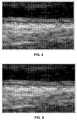
- FIG. 9shows the detection of the lumen-intima interface (the upper border) and the media-adventitia interface (lower border) using other detection approaches;
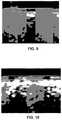
- FIG. 10shows the detection of the lumen-intima interface (the upper border) and the media-adventitia interface (lower border) in accordance with some embodiments of the disclosed subject matter
- FIG. 11is an illustrative display showing the detection of smooth edges of the carotid artery in accordance with some embodiments of the disclosed subject matter
- FIG. 12is an illustrative display showing the display of FIG. 11 with an indicator that corresponds to the maximum carotid intima-media thickness in accordance with some embodiments of the disclosed subject matter:
- FIG. 13is an illustrative display showing the display of FIG. 11 with color indicators that indicate the varying carotid intima-media thickness along the carotid artery in accordance with some embodiments of the disclosed subject matter;
- FIG. 14shows an illustrative system for implementing the image interpretation application in accordance with some embodiments of the disclosed subject matter.
- an image interpretation application for determining carotid intima-media thickness(sometimes referred to herein as “the application”) is provided.
- the image interpretation applicationcan receive an ultrasound image of a carotid artery, set a region of interest in the ultrasound image that contains a portion of the carotid artery, and detect the borders of the carotid artery. Active contour models or snake models and, in some embodiments, user-inputted constraints, can then be applied to the detected borders.
- the image interpretation applicationprovides users with an accurate, adaptive, and user-friendly approach for detecting borders of the carotid artery.
- the image interpretation applicationcan perform a variety of measurements. For example, the image interpretation application can determine the carotid intima-media thickness. In another example, the image interpretation application can determine the vascular age of a carotid artery.
- FIG. 1shows an illustrative flow diagram 100 for detecting carotid intima-media thickness and other suitable measurements using active contour models in accordance with some embodiments of the disclosed subject matter.
- the image interpretation applicationcan receive multiple images of the carotid artery from an ultrasound imaging device.
- the ultrasound imaging devicecan be connected to a processor that is executing the image interpretation application.
- the carotid artery of a patientcan be imaged using a high resolution B-mode ultrasound imaging device with an 8-14 MHz linear array transducer utilizing fundamental frequency.
- the transducertransmits ultrasound signals into a portion of the patient underneath the transducer and receives echo signals reflected from that portion.
- a carotid artery plaque screencan be performed in the transverse and longitudinal axis, revealing the common carotid artery (CCA), the carotid bulb, the carotid bifurcation, and the internal and external carotid arteries.
- CCAcommon carotid artery
- far wall lumen-intima and media-adventitia interface at the level of the common carotid arterycan be adjusted by modifying overall gain, time gain compensation, and focus position.
- the image interpretation applicationcan cause the received images to be displayed to the user.
- the image interpretation applicationcan access a storage location to retrieve the multiple images for display.
- the image interpretation applicationcan update and display the multiple images as the images are being captured using the ultrasound imaging device.
- the image interpretation applicationcan receive the multiple images of the carotid artery in response to establishing a connection with the ultrasound imaging device (e.g., a wired connection or a wireless connection). More particularly, in some embodiments, the ultrasound imaging device can transmit the images to the image interpretation application.
- the image interpretation applicationcan receive a user selection of an image or a frame at 120 .
- the image interpretation applicationpresents the user with display screen 200 that includes multiple ultrasound images 210 (e.g., each image is labeled by a file name, such as DIRW0006, DIRW0007, and DIRW0008).
- Display screen 200shows that additional images can be displayed in response to the user selecting one of the navigational icons 220 . (Pressing an arrow key on a user input device may affect display screen 200 in a similar manner as selecting navigational icon 220 .)
- FIG. 1As also shown in FIG.
- the userhas selected or identified a single, end-diastolic still frame for intima-media measurement analysis (which is indicated as frame number 3 out of 82 frames or images).
- the image interpretation applicationcan cause the selected image to be displayed in image window 230 .
- the image interpretation applicationcan receive a user selection of a point within the selected image at 130 .
- a user using a user input devicee.g., a mouse, a trackball, a keyboard, etc.
- the image interpretation applicationcan set a region of interest within the user-selected image at 140 .
- the image interpretation applicationsets a region of interest 235 within image 230 for detecting the borders of the carotid artery and calculating carotid intima-media thickness measurements and vascular age.
- the region of interest 235is about one centimeter in length and about 0.65 centimeters in height.
- any suitable region of interestcan be provided by the image interpretation application.
- the user selection of a portion of the ultrasound imageis the only user selection received prior to automatically measuring the carotid intima-media thickness from the image.
- the image interpretation applicationcan automatically set a region of interest, detect edge lines or other image information from the region of interest (e.g., initialize by detecting rough edges and smooth those rough edges with one or more active contour models), and calculate a number of parameters, such as a mean carotid intima-media thickness value, a maximum carotid intima-media thickness value, a mean of the maximum carotid intima-media thickness values, and/or a vascular age. As illustrated in region 240 of FIG.
- the image interpretation applicationplaces the region of interest 235 , detects the edge lines corresponding to the lumen-intima interface and the media-adventitia interface, and determines that the carotid artery in the selected image has a mean carotid intima-media thickness of 0.67571 millimeters, a maximum carotid intima-media thickness of 0.80821 millimeters, and a vascular age of 43.62.
- the image interpretation applicationcan provide the user with the opportunity to modify or adjust the region of interest.
- the image interpretation applicationcan allow the user to move the region of interest to a different area within the ultrasound image.
- the image interpretation applicationcan allow the user to change the dimensions of the region of interest (e.g., the height, the length, the aspect ratio, etc.).
- the image interpretation applicationcan allow the user to modify the shape of the region of interest (e.g., from a rectangular region of interest to a circular region of interest).
- the image interpretation applicationcan detect the edges or borders of the carotid artery within the region of interest at 150 .
- the image interpretation applicationbegins by obtaining rough or preliminary borders of the carotid artery. That is, the image interpretation application performs an initialization that includes obtaining rough or preliminary borders of the carotid artery.
- the image interpretation applicationperforms an accurate initialization that includes a preliminary detection of the borders of the carotid artery within the region of interest.
- FIG. 3shows an illustrative flow diagram 300 for detecting preliminary borders within a region of interest in accordance with some embodiments of the disclosed subject matter.
- the image interpretation applicationbegins by calculating the gradient of the image at each point of the user selected image within the region of interest 315 to form a gradient image.
- the determination of the gradient of the imagecan provide, for example, an indication of the change in the intensity or color in the image such that information (such as a border) can be derived.
- the image interpretation applicationcan apply one or more thresholds to generate a binary gradient mask at 320 . That is, the gradient image can be calculated and a threshold can be applied to create a binary mask containing the segmented edges.
- the image interpretation applicationcan use a Sobel operator or any other suitable operator to calculate the threshold value, where the threshold value is tuned and used to obtain a binary mask that contains the segmented edges.
- the binary gradient mask shown in window 325provides lines of high contrast in the image.
- the lines in the binary gradient maskmay not delineate the outline of the object of interest.
- multiple short lines and unconnected targeted edge linese.g., gaps
- the image interpretation applicationcan dilate the binary gradient mask using linear structuring elements to enhance the connectivity of the edge lines in the horizontal direction.
- An example of a dilated gradient mask using linear structuring elementsis shown in window 335 .
- the image interpretation applicationcan remove at least a portion of the features (e.g., lines with small pixel sizes) from the dilated binary gradient mask to form an updated binary image.
- a connect component approachcan be applied to the dilated gradient mask shown in window 345 to extract features with small pixel sizes.
- An example of the updated binary image with extracted featuresis shown in window 345 .
- the image interpretation applicationcan determine a first border at 350 and, based on the first detected border, the image interpretation can determine a second border at 360 .
- the upper border of the carotid lumen-intima interfacecan be designed as the first edge line while scanning from the top of the updated binary image.
- An example of the detected upper border of the carotid lumen-intima interfaceis shown in window 355 .
- the lower border of the carotid media-adventitia interfacecan then be detected based on the detected upper border of the carotid lumen-intima interface.
- the image interpretation applicationcan scan from the detected upper border edge and down each column of pixels to obtain the pixel having the smallest value in gradient image.
- An illustrative example of the preliminary edge detection performed by the image interpretation applicationis shown in FIG. 4 . As shown, the image interpretation application has detected the border of the carotid lumen-intima interface and a border of the carotid media-adventitia interface.
- the image interpretation applicationcan apply one or more active contour models to smoothen out the detected edge lines at 160 . More particularly, the preliminary edges detected by the image interpretation application are used as the initial contours for the active contour model.
- An active contour model(sometimes referred to herein as a “snake” or a “snake model”) is a controlled continuity spline under the influence of internal forces and external forces.
- E snake *( ⁇ ( s ) ds )⁇ 0 1 E int ( ⁇ ( s ))+ E ext ( ⁇ ( s )) ds
- the first term in the energy functionis the internal spline energy, which can be represented by:
- T ⁇ ( v )1 2 ⁇ ⁇ 0 L ⁇ ⁇ ⁇ ( s ) ⁇ ⁇ ⁇ v ⁇ s ⁇ 2 + ⁇ ⁇ ( s ) ⁇ ⁇ ⁇ ⁇ 2 ⁇ v ⁇ s 2 ⁇ 2 ⁇ d s
- ⁇ (s)controls the “tension” of the contour
- ⁇ (s)regulates the “rigidity” of the contour.
- P 1 ( ⁇ )This can couple the snake to the image via a scalar potential function P 1 ( ⁇ ), which is generally calculated from l(x,y) through image processing.
- P 1 ( ⁇ )The Euler-Lagrange equations of motion for a dynamic snake can then be defined as:
- the first two terms in the above-mentioned equationrepresent inertial forces due to the mass density, ⁇ (s), and damping forces due to the dissipation density, ⁇ (s), respectively.
- the following two terms in the above-mentioned equationrepresent the internal stretching and bending deformation forces.
- the image forcesare the negative gradient of the image potential function.
- the image interpretation applicationcan allow the user to guide the dynamic snake via time-varying interaction forces, f(s,t). These forces can be applied to the snake through a user input device, such as a mouse, thereby driving the snake out of one energy minimizing equilibrium and into another.
- the image interpretation applicationcan divide the snake contour into multiple snake elements. More particularly, the parametric domain can be partitioned into finite subdomains. Each element, e, can be represented geometrically using shape functions N(s) and nodal variables u e (t). The nodal variables of the elements are assembled into the snake nodal variable vector u(t).
- the image interpretation applicationcan apply an active contour model to obtain smoothed edges or borders of the carotid artery.
- the active contour modelcauses the preliminary detected edge lines to be smooth and adherent to the gradient value of the region of interest.
- FIG. 4illustrates the initialization approach where the image interpretation application detects preliminary edges
- FIG. 5illustrates the smoothed edge lines that result after applying one or more active contour models to the preliminary edge lines of FIG. 4 .
- the display screen 200 of FIG. 2illustrates that, upon setting a region of interest, the image interpretation application obtains smooth edge lines of the carotid artery. More particularly, the upper border of the lumen-intima interface and the lower border of the media-adventitia interface are detected and shown within region of interest 235 and enlarged in window 250 . These portions of FIG. 2 have been enlarged and are shown in FIGS. 6 and 7 , respectively.
- the image interpretation applicationcan provide the user with the opportunity to modify a smoothed edge line. For example, upon the user determining that the edge line detected from the border edge detection is not satisfactory (e.g., due to noise in the image or an image artifact, based on experience or judgment, etc.), the image interpretation application can allow the user to adjust the edge line.
- the image interpretation applicationcan allow the user to modify a smoothed edge line with constraints or control points.
- FIG. 8shows an illustrative display screen for modifying the detected edge lines of the carotid artery.
- the image interpretation applicationhas detected a first edge line 810 and a second edge line 820 of the carotid artery.
- the image interpretation applicationprovides the user with the opportunity to set hard constraints or control points for an edge line such that the edge line is directed to pass through the indicated control points (e.g., control points 830 and 840 ). More particularly, while calculating and displaying the edge line, the placement of hard constraints 830 and 840 causes the image interpretation application and its active contour model to provide an edge line that passes the user-positioned constraints or control points.
- the image interpretation applicationcan update the edge line using the active contour model as the user moves a hard constraint.
- the user using a user input devicecan drag hard constraint 830 causing the image interpretation application to update the edge line with the current position of moveable hard constraint 830 and fixed hard constraints 840 .
- the image interpretation applicationcan allow the user to remove hard constraints, add any suitable number of hard constraints, etc.
- the image interpretation applicationcan place hard constraints at the ends of the edge lines to inhibit them from shrinking or expanding in the horizontal direction.
- constraints and/or other suitable modifications to the edge linescan be provided by mouse interaction or any other suitable interaction using a user input device.
- the usermay make contact with the touch screen using any suitable object or appendage, such as a stylus, finger, etc.
- the image interpretation applicationmay respond to contact with a touch screen, such as one or more taps on the touch screen, maintaining continuous contact with the touch screen, movement of the point of contact while maintaining continuous contact, a breaking of the contact, or any combination thereof.
- the image interpretation applicationcan allow a user to insert control points on an edge line with the use of a user input device. As shown in FIG. 8 , the image interpretation application allows the user to click on a portion of edge line 810 . In response to selecting a point on edge line 810 , the image interpretation application can create control point 830 . When the user maintains contact with control point 830 (e.g., by holding the mouse button down, by maintaining continuous contact with a touch screen, etc.), the image interpretation application can allow the user to move control point 830 to a different location, where one or more active contour models are used to update the edge line to pass through control point 830 at its current position and other control points 840 .
- control point 830e.g., by holding the mouse button down, by maintaining continuous contact with a touch screen, etc.
- the image interpretation applicationcan allow a user to remove control points from an edge line. As shown in FIG. 8 , in response to the user selecting an inserted control point (e.g., one of control points 830 or 840 ), the image interpretation application can provide the user with the option to remove the inserted control point. In response to removing an inserted control point, the image interpretation application can use one or more active contour models to update the edge line to pass through the remaining control points.
- an inserted control pointe.g., one of control points 830 or 840
- the image interpretation applicationcan use one or more active contour models to update the edge line to pass through the remaining control points.
- the image interpretation applicationcan allow a user to correct or modify control points from an edge line.
- the image interpretation applicationin response to the user selecting an inserted control point (e.g., one of control points 830 or 840 ), the image interpretation application can provide the user with the option to modify the position of the inserted control point.
- the image interpretation applicationcan use one or more active contour models to update the edge line to pass through the control points, which includes the inserted control point at its new location.
- the image interpretation applicationcan allow a user to set particular designations for particular control points. For example, using a user input device, the image interpretation application can allow the user to designate that control point 830 is a measurement point for determining the carotid intima-media thickness. In response, the image interpretation application can determine the orthogonal distance from control point 830 on one edge line to the opposing edge line and present the measurement to the user.
- the image interpretation applicationcan then determine one or more measurements relating to the carotid artery using the detected edge lines at 180 .
- the image interpretation applicationcan determine a mean intima-media thickness value.
- the image interpretation applicationcan determine the length of a line orthogonal from the detected media-adventitia border to the detected lumen-intima border for each of the points along the length of the region of interest within the carotid artery.
- the mean carotid intima-media thickness valuecan be the arithmetic mean value of these determined lengths.
- the image interpretation applicationcan determine the maximum value of these lengths to derive the maximum carotid intima-media thickness value.
- the image interpretation applicationcan determine a mean of the maximum carotid intima-media thickness values.
- the image interpretation applicationcan determine a vascular age of the carotid artery in the selected ultrasound image.
- the image interpretation applicationcan transmit a query to a storage device (e.g., a database that relates age to carotid intima-media thickness values in a particular study population).
- the image interpretation applicationcan receive the associated vascular age and cause the vascular age to be displayed to the user.
- the image interpretation applicationhas queries a population database and determined that the vascular age of the carotid artery shown in window 230 is 43.62 years of age.
- the image interpretation applicationaccesses the median value (50th percentile) in a Bogalusa study database of a given race and gender.
- FIGS. 9 and 10show an illustrative comparison of the detection of the borders of a carotid artery using other detection approaches with the detection of the borders of the carotid artery of the same patient using the image interpretation application in accordance with some embodiments of the disclosed subject matter.
- the borders or edge lines detected by the image interpretation applicationprovide a more accurate fit of the lumen-intima interface and the media-adventitia interface of the carotid artery.
- the image interpretation applicationcan provide the user with various color indicators corresponding to carotid intima-media thickness and/or edge lines.
- color indicatorscan overlay particular portions of the illustrative displays (e.g., over an edge line, over sections of an artery, over particular measurements, etc.) or otherwise displayed to provide the user with a visual recognition of particular conditions.
- the image interpretation applicationcan provide the user with a visual indication of the range of thicknesses along a carotid artery—e.g., the region of the carotid artery with the maximum carotid intima-media thickness, the region of the carotid artery with the minimum carotid intima-media thickness, etc.
- the image interpretation applicationcan provide the user with visual color cues for particular conditions, such as blue to indicate a thin intima media-thickness and red to indicate a thick intima-media thickness.
- FIG. 11shows two edge lines that have been detected using the image interpretation application.
- the image interpretation applicationcan use color cues to indicate the detection of particular edge lines.
- the detection of the lumen-intima interfacecan be shown by a green line 1110 and the detection of the media-adventitia interface can be shown by a red line 1120 .
- any suitable colorcan be used such that the user is provided with a visual indication of the detected interfaces.
- FIG. 12includes a measurement line 1210 .
- the image interpretation applicationcan display measurement line 1210 in yellow to indicate the orthogonal line that provides the maximum carotid intima-media thickness within the region of interest.
- the image interpretation applicationcan allow the user to move measurement line 1210 .
- the image interpretation applicationcan allow the user to move measurement line 1210 to another position within the region of interest.
- the image interpretation applicationcan provide the user with the carotid intima-media thickness value corresponding to the position of measurement line 1210 .
- multiple measurement linescan be provided on the illustrative display—e.g., one measurement line corresponding to the location having the maximum carotid intima-media thickness, one measurement line corresponding to the location having the minimum carotid intima-media thickness, and/or one movable measurement line providing the carotid intima-media thickness value corresponding to its position.
- FIG. 13shows an illustrative example of a color-coded scheme or color indicators along the carotid artery.
- the carotid artery within the region of interestcan be divided into sections 1310 , 1320 , 1330 , 1340 , 1350 , 1360 , 1370 , and 1380 , where each section is assigned a color or shading based on the carotid intima-media thickness value or vascular age value (e.g., blue to indicate that the section of the carotid artery is within a normal carotid intima-media thickness range and red to indicate that the section of the carotid artery is within a significantly abnormal carotid intima-media thickness range).
- vascular age valuee.g., blue to indicate that the section of the carotid artery is within a normal carotid intima-media thickness range and red to indicate that the section of the carotid artery is within a significantly abnormal carotid intima-media
- gradient shading or heat mappingcan be used to show that the carotid intima-media thickness of section 1310 is significantly thicker than the carotid intima-media thickness of section 1350 .
- gradient shading or heat mappingcan be used to show changes in carotid intima-media thickness, where the red color assigned to section 1310 (to indicate a thick carotid intima-media thickness) transitions to the orange color assigned to neighboring section 1320 . This can indicate the change in thickness and the direction of the change in thickness (e.g., that the carotid intima-media thickness decreases from section 1310 to section 1320 ).
- the image interpretation applicationcan provide a color range indicator.
- the image interpretation applicationcan display a color range indicator that provides a guide as to which sections are in a particular range of carotid intima-media thicknesses.
- the image interpretation applicationcan display a color range indicator that indicates which portions of the carotid artery are within a normal carotid intima-media thickness range (blue), a moderately abnormal carotid intima-media thickness range (green), and a significantly abnormal carotid intima-media thickness range (red).
- the image interpretation applicationcan receive x-ray computed tomography images.
- the image interpretation applicationcan analyze the images and calculate spinal disc measurements, such as the distance between particular discs and the amount a particular disc is compressed.
- the image interpretation applicationcan detect the borders of a bone and calculate measurements based on the detected borders, such as the length of a bone, the amount of displacement,
- the image interpretation applicationcan receive fetal ultrasound images of a fetus, where the image interpretation application detects edge lines corresponding to the fetus and calculates measurements based on the detected edge lines, such as the length of the fetus, size of the baby's head, etc.
- the image interpretation applicationcan determine the carotid-intima media thickness of a patient's carotid artery and, in response to determining that the patient has atherosclerosis, the image interpretation application can transmit a message to a doctor.
- the image interpretation applicationcan detect borders and perform various measurements using an ultrasound imaging device on any suitable artery, such as the brachial, radial, and/or femoral arteries.
- FIG. 14shows a generalized embodiment of an illustrative system 1400 on which the image interpretation application can be implemented in accordance with some embodiments of the disclosed subject matter.
- the illustrative system 1400includes a computing device 1410 and an ultrasound imaging device 1420 .
- Computing device 1410can be any suitable computing device for providing access to the image interpretation application, such as a processor, a computer, a data processing device, or a combination of such devices.
- the image interpretation applicationcan be distributed into multiple backend components and multiple frontend components or interfaces.
- backend componentssuch as data collection and data distribution can be performed on ultrasound imaging device 1420 .
- the graphical user interfaces displayed by the applicationsuch as an interface for displaying ultrasound images and measuring carotid intima-media thickness, can be distributed by one or more computing devices 1410 .
- Ultrasound imaging device 1420can be any suitable imaging device, such as a high resolution B-mode ultrasound imaging device with an 8-14 MHz linear array transducer utilizing fundamental frequency.
- any suitable imaging devicee.g., x-ray imaging device, magnetic resonance imaging device, etc.
- computing device 1410can be any of a general purpose device such as a computer or a special purpose device such as a client, a server, etc. Any of these general or special purpose devices can include any suitable components such as a processor (which can be a microprocessor, digital signal processor, a controller, etc.), memory, communication interfaces, display controllers, input devices, etc.
- client 1410can be implemented as a personal computer, a tablet computing device, a personal data assistant (PDA), a portable email device, a multimedia terminal, a mobile telephone, a gaming device, a set-top box, a television, etc.
- PDApersonal data assistant
- any suitable computer readable mediacan be used for storing instructions for performing the processes described herein, can be used to determine carotid intima-media thickness, etc.
- computer readable mediacan be transitory or non-transitory.
- non-transitory computer readable mediacan include media such as magnetic media (such as hard disks, floppy disks, etc.), optical media (such as compact discs, digital video discs, Blu-ray discs, etc.), semiconductor media (such as flash memory, electrically programmable read only memory (EPROM), electrically erasable programmable read only memory (EEPROM), etc.), any suitable media that is not fleeting or devoid of any semblance of permanence during transmission, and/or any suitable tangible media.
- transitory computer readable mediacan include signals on networks, in wires, conductors, optical fibers, circuits, any suitable media that is fleeting and devoid of any semblance of permanence during transmission, and/or any suitable intangible media.
- communications link 1430may be any communications links suitable for communicating data between computing device 1410 and ultrasound imaging device 1420 , such as network links, dial-up links, wireless links, hard-wired links, any other suitable communications links, or a combination of such links.
- Computing device 1410enables a user to access features of the image interpretation application.
- Computing device 1410may be personal computers, laptop computers, mainframe computers, dumb terminals, data displays, Internet browsers, personal digital assistants (“PDAs”), two-way pagers, wireless terminals, portable telephones, any other suitable access device, or any combination of such devices.
- Computing device 1410 and ultrasound imaging device 1420may be located at any suitable location. In one embodiment, computing device 1410 and ultrasound imaging device 1420 may be located within an organization. Alternatively, computing device 1410 and ultrasound imaging device 1420 may be distributed between multiple organizations.
- computing device 1410can include processor 1440 , memory 1450 , input device 1460 , and display 1470 , which may be interconnected.
- memory 1450contains a storage device for storing a computer program for controlling processor 1440 .
- Processor 1440uses the computer program to present on display 1470 the image interpretation application and the data received through communications link 1430 and commands and values transmitted by a user of computing device 1410 . It should also be noted that data received through communications link 1430 or any other communications links may be received from any suitable source.
- Input device 1460may be a computer keyboard, a mouse, a cursor-controller, dial, switchbank, lever, or any other suitable input device as would be used by a designer of input systems or process control systems. Alternatively, input device 1460 may be a finger or stylus used on a touch screen display 1470 .
- the image interpretation applicationmay include an application program interface (not shown), or alternatively, the application may be resident in the memory of computing device 1410 .
- the only distribution to computing device 1410may be a graphical user interface (“GUI”) which allows a user to interact with the image interpretation application resident at, for example, another computing device.
- GUIgraphical user interface
- the image interpretation applicationmay include client-side software, hardware, or both.
- the applicationmay encompass one or more Web-pages or Web-page portions (e.g., via any suitable encoding, such as HyperText Markup Language (“HTML”), Dynamic HyperText Markup Language (“DHTML”), Extensible Markup Language (“XML”), JavaServer Pages (“JSP”), Active Server Pages (“ASP”), Cold Fusion, or any other suitable approaches).
- HTMLHyperText Markup Language
- DHTMLDynamic HyperText Markup Language
- XMLExtensible Markup Language
- JSPJavaServer Pages
- ASPActive Server Pages
- Cold Fusionor any other suitable approaches.
Landscapes
- Health & Medical Sciences (AREA)
- Life Sciences & Earth Sciences (AREA)
- Engineering & Computer Science (AREA)
- Physics & Mathematics (AREA)
- Medical Informatics (AREA)
- General Health & Medical Sciences (AREA)
- Public Health (AREA)
- Pathology (AREA)
- Biomedical Technology (AREA)
- Veterinary Medicine (AREA)
- Heart & Thoracic Surgery (AREA)
- Nuclear Medicine, Radiotherapy & Molecular Imaging (AREA)
- Molecular Biology (AREA)
- Surgery (AREA)
- Animal Behavior & Ethology (AREA)
- Biophysics (AREA)
- Radiology & Medical Imaging (AREA)
- Computer Vision & Pattern Recognition (AREA)
- Vascular Medicine (AREA)
- Physiology (AREA)
- Theoretical Computer Science (AREA)
- General Physics & Mathematics (AREA)
- Quality & Reliability (AREA)
- Cardiology (AREA)
- Human Computer Interaction (AREA)
- Geometry (AREA)
- Computer Networks & Wireless Communication (AREA)
- Primary Health Care (AREA)
- Epidemiology (AREA)
- Databases & Information Systems (AREA)
- Data Mining & Analysis (AREA)
- Ultra Sonic Daignosis Equipment (AREA)
Abstract
Description
ν(s)=(s(s),y(s))
The energy function of the snake can then be represented by:
Esnake*=∫01Esnake*(ν(s)ds)=∫01Eint(ν(s))+Eext(ν(s))ds
The first term in the energy function is the internal spline energy, which can be represented by:
where α(s) controls the “tension” of the contour and β(s) regulates the “rigidity” of the contour. The second term in the energy function is an external image energy function, which can be represented as:
P(ν)=∫0LP1(ν)ds
This can couple the snake to the image via a scalar potential function P1(ν), which is generally calculated from l(x,y) through image processing. The Euler-Lagrange equations of motion for a dynamic snake can then be defined as:
It should be noted that the first two terms in the above-mentioned equation represent inertial forces due to the mass density, μ(s), and damping forces due to the dissipation density, γ(s), respectively. The following two terms in the above-mentioned equation represent the internal stretching and bending deformation forces. The right hand side of the above-mentioned equation includes the external forces, where q(ν)=−∇P1(ν)+f(s, t). The image forces are the negative gradient of the image potential function.
Mü+C{dot over (u)}+Ku=g
where M is the mass matrix, C is the damping matrix, K is the stiffness matrix, and g is the external force vector, which are assembled from corresponding element sub-matrices that depend on the shape functions N.
Claims (33)
Priority Applications (1)
| Application Number | Priority Date | Filing Date | Title |
|---|---|---|---|
| US13/984,800US10610203B2 (en) | 2011-02-11 | 2012-02-13 | Methods, systems, and media for determining carotid intima-media thickness |
Applications Claiming Priority (3)
| Application Number | Priority Date | Filing Date | Title |
|---|---|---|---|
| US201161442169P | 2011-02-11 | 2011-02-11 | |
| PCT/US2012/024925WO2012109676A1 (en) | 2011-02-11 | 2012-02-13 | Methods, systems, and media for determining carotid intima-media thickness |
| US13/984,800US10610203B2 (en) | 2011-02-11 | 2012-02-13 | Methods, systems, and media for determining carotid intima-media thickness |
Publications (2)
| Publication Number | Publication Date |
|---|---|
| US20140135627A1 US20140135627A1 (en) | 2014-05-15 |
| US10610203B2true US10610203B2 (en) | 2020-04-07 |
Family
ID=46638996
Family Applications (1)
| Application Number | Title | Priority Date | Filing Date |
|---|---|---|---|
| US13/984,800Active2036-06-18US10610203B2 (en) | 2011-02-11 | 2012-02-13 | Methods, systems, and media for determining carotid intima-media thickness |
Country Status (5)
| Country | Link |
|---|---|
| US (1) | US10610203B2 (en) |
| EP (1) | EP2672890A1 (en) |
| AU (1) | AU2012214149A1 (en) |
| CA (1) | CA2827122A1 (en) |
| WO (1) | WO2012109676A1 (en) |
Cited By (15)
| Publication number | Priority date | Publication date | Assignee | Title |
|---|---|---|---|---|
| US10956785B2 (en) | 2018-04-27 | 2021-03-23 | Arizona Board Of Regents On Behalf Of Arizona State University | Methods, systems, and media for selecting candidates for annotation for use in training classifiers |
| US11100685B2 (en) | 2018-08-29 | 2021-08-24 | Arizona Board Of Regents On Behalf Of Arizona State University | Method and apparatus for detection and visualization of pulmonary embolism |
| US11164067B2 (en) | 2018-08-29 | 2021-11-02 | Arizona Board Of Regents On Behalf Of Arizona State University | Systems, methods, and apparatuses for implementing a multi-resolution neural network for use with imaging intensive applications including medical imaging |
| US11232564B2 (en)* | 2020-01-07 | 2022-01-25 | Cleerly, Inc. | Systems, methods, and devices for medical image analysis, diagnosis, risk stratification, decision making and/or disease tracking |
| US11238562B2 (en)* | 2017-08-17 | 2022-02-01 | Koninklijke Philips N.V. | Ultrasound system with deep learning network for image artifact identification and removal |
| US11244472B2 (en)* | 2019-05-23 | 2022-02-08 | Brainlab Ag | Method, system and computer program for determining position and/or orientation parameters of an anatomical structure |
| US11278260B1 (en) | 2021-07-09 | 2022-03-22 | Qure.Ai Technologies Private Limited | Acquiring ultrasound image |
| US12118455B2 (en) | 2017-04-27 | 2024-10-15 | Arizona Board Of Regents On Behalf Of Arizona State University | Systems, methods, and/or media, for selecting candidates for annotation for use in training a classifier |
| US12283046B2 (en) | 2020-01-07 | 2025-04-22 | Cleerly, Inc. | Systems, methods, and devices for medical image analysis, diagnosis, risk stratification, decision making and/or disease tracking |
| US12299885B2 (en) | 2022-03-10 | 2025-05-13 | Cleerly, Inc. | Systems, devices, and methods for non-invasive image-based plaque analysis and risk determination |
| US12322098B2 (en) | 2021-09-07 | 2025-06-03 | Arizona Board Of Regents On Behalf Of Arizona State University | Systems, methods, and apparatuses for generating pre-trained models for nnU-net through the use of improved transfer learning techniques |
| US12324695B2 (en) | 2020-01-07 | 2025-06-10 | Cleerly, Inc. | Systems, methods, and devices for medical image analysis, diagnosis, risk stratification, decision making and/or disease tracking |
| US12324696B2 (en) | 2022-03-10 | 2025-06-10 | Cleerly, Inc. | Systems, devices, and methods for non-invasive image-based plaque analysis and risk determination |
| US12380560B2 (en) | 2022-03-10 | 2025-08-05 | Cleerly, Inc. | Systems, methods, and devices for image-based plaque analysis and risk determination |
| US12440180B2 (en) | 2024-02-29 | 2025-10-14 | Cleerly, Inc. | Systems, devices, and methods for non-invasive image-based plaque analysis and risk determination |
Families Citing this family (62)
| Publication number | Priority date | Publication date | Assignee | Title |
|---|---|---|---|---|
| US9867530B2 (en) | 2006-08-14 | 2018-01-16 | Volcano Corporation | Telescopic side port catheter device with imaging system and method for accessing side branch occlusions |
| EP2178442B1 (en) | 2007-07-12 | 2017-09-06 | Volcano Corporation | Catheter for in vivo imaging |
| WO2009009802A1 (en) | 2007-07-12 | 2009-01-15 | Volcano Corporation | Oct-ivus catheter for concurrent luminal imaging |
| US9596993B2 (en) | 2007-07-12 | 2017-03-21 | Volcano Corporation | Automatic calibration systems and methods of use |
| US11141063B2 (en) | 2010-12-23 | 2021-10-12 | Philips Image Guided Therapy Corporation | Integrated system architectures and methods of use |
| US11040140B2 (en) | 2010-12-31 | 2021-06-22 | Philips Image Guided Therapy Corporation | Deep vein thrombosis therapeutic methods |
| US9360630B2 (en) | 2011-08-31 | 2016-06-07 | Volcano Corporation | Optical-electrical rotary joint and methods of use |
| JP2014050681A (en)* | 2012-08-06 | 2014-03-20 | Seiko Epson Corp | Ultrasonic measuring apparatus and blood vessel diameter calculation method |
| CA2887421A1 (en) | 2012-10-05 | 2014-04-10 | David Welford | Systems and methods for amplifying light |
| US9367965B2 (en) | 2012-10-05 | 2016-06-14 | Volcano Corporation | Systems and methods for generating images of tissue |
| US9292918B2 (en) | 2012-10-05 | 2016-03-22 | Volcano Corporation | Methods and systems for transforming luminal images |
| US20140100454A1 (en) | 2012-10-05 | 2014-04-10 | Volcano Corporation | Methods and systems for establishing parameters for three-dimensional imaging |
| WO2014055923A2 (en)* | 2012-10-05 | 2014-04-10 | Elizabeth Begin | System and method for instant and automatic border detection |
| US10568586B2 (en) | 2012-10-05 | 2020-02-25 | Volcano Corporation | Systems for indicating parameters in an imaging data set and methods of use |
| US9307926B2 (en) | 2012-10-05 | 2016-04-12 | Volcano Corporation | Automatic stent detection |
| US9324141B2 (en) | 2012-10-05 | 2016-04-26 | Volcano Corporation | Removal of A-scan streaking artifact |
| US9858668B2 (en) | 2012-10-05 | 2018-01-02 | Volcano Corporation | Guidewire artifact removal in images |
| US10070827B2 (en) | 2012-10-05 | 2018-09-11 | Volcano Corporation | Automatic image playback |
| US11272845B2 (en) | 2012-10-05 | 2022-03-15 | Philips Image Guided Therapy Corporation | System and method for instant and automatic border detection |
| US9286673B2 (en) | 2012-10-05 | 2016-03-15 | Volcano Corporation | Systems for correcting distortions in a medical image and methods of use thereof |
| US9840734B2 (en) | 2012-10-22 | 2017-12-12 | Raindance Technologies, Inc. | Methods for analyzing DNA |
| CN102982314B (en)* | 2012-11-05 | 2016-05-25 | 深圳市恩普电子技术有限公司 | Adventitia identification in a kind of blood vessel, the method for tracing and measuring |
| EP2931132B1 (en) | 2012-12-13 | 2023-07-05 | Philips Image Guided Therapy Corporation | System for targeted cannulation |
| US10942022B2 (en) | 2012-12-20 | 2021-03-09 | Philips Image Guided Therapy Corporation | Manual calibration of imaging system |
| US11406498B2 (en) | 2012-12-20 | 2022-08-09 | Philips Image Guided Therapy Corporation | Implant delivery system and implants |
| WO2014113188A2 (en) | 2012-12-20 | 2014-07-24 | Jeremy Stigall | Locating intravascular images |
| US10939826B2 (en) | 2012-12-20 | 2021-03-09 | Philips Image Guided Therapy Corporation | Aspirating and removing biological material |
| EP2934311B1 (en) | 2012-12-20 | 2020-04-15 | Volcano Corporation | Smooth transition catheters |
| EP2934310A4 (en) | 2012-12-20 | 2016-10-12 | Nathaniel J Kemp | Optical coherence tomography system that is reconfigurable between different imaging modes |
| EP2934323A4 (en) | 2012-12-21 | 2016-08-17 | Andrew Hancock | SYSTEM AND METHOD FOR MULTIPLE PROCESSING OF IMAGE SIGNALS |
| JP2016507892A (en) | 2012-12-21 | 2016-03-10 | デイビッド ウェルフォード, | System and method for narrowing the wavelength emission of light |
| US9612105B2 (en) | 2012-12-21 | 2017-04-04 | Volcano Corporation | Polarization sensitive optical coherence tomography system |
| US9486143B2 (en) | 2012-12-21 | 2016-11-08 | Volcano Corporation | Intravascular forward imaging device |
| US10058284B2 (en) | 2012-12-21 | 2018-08-28 | Volcano Corporation | Simultaneous imaging, monitoring, and therapy |
| US10332228B2 (en) | 2012-12-21 | 2019-06-25 | Volcano Corporation | System and method for graphical processing of medical data |
| CA2895769A1 (en) | 2012-12-21 | 2014-06-26 | Douglas Meyer | Rotational ultrasound imaging catheter with extended catheter body telescope |
| EP2936241B1 (en) | 2012-12-21 | 2020-10-21 | Nathaniel J. Kemp | Power-efficient optical buffering using a polarisation-maintaining active optical switch |
| US10413317B2 (en) | 2012-12-21 | 2019-09-17 | Volcano Corporation | System and method for catheter steering and operation |
| JP2016501625A (en) | 2012-12-21 | 2016-01-21 | ジェローム マイ, | Ultrasound imaging with variable line density |
| WO2014138555A1 (en) | 2013-03-07 | 2014-09-12 | Bernhard Sturm | Multimodal segmentation in intravascular images |
| US10226597B2 (en) | 2013-03-07 | 2019-03-12 | Volcano Corporation | Guidewire with centering mechanism |
| US20140276923A1 (en) | 2013-03-12 | 2014-09-18 | Volcano Corporation | Vibrating catheter and methods of use |
| EP2967391A4 (en) | 2013-03-12 | 2016-11-02 | Donna Collins | SYSTEMS AND METHODS FOR DIAGNOSING CORONARY MICROVASCULAR DISEASE |
| US9301687B2 (en) | 2013-03-13 | 2016-04-05 | Volcano Corporation | System and method for OCT depth calibration |
| US11026591B2 (en) | 2013-03-13 | 2021-06-08 | Philips Image Guided Therapy Corporation | Intravascular pressure sensor calibration |
| WO2014159819A1 (en) | 2013-03-13 | 2014-10-02 | Jinhyoung Park | System and methods for producing an image from a rotational intravascular ultrasound device |
| US10219887B2 (en) | 2013-03-14 | 2019-03-05 | Volcano Corporation | Filters with echogenic characteristics |
| US20160030151A1 (en) | 2013-03-14 | 2016-02-04 | Volcano Corporation | Filters with echogenic characteristics |
| US12343198B2 (en) | 2013-03-14 | 2025-07-01 | Philips Image Guided Therapy Corporation | Delivery catheter having imaging capabilities |
| US10292677B2 (en) | 2013-03-14 | 2019-05-21 | Volcano Corporation | Endoluminal filter having enhanced echogenic properties |
| WO2015142808A1 (en)* | 2014-03-17 | 2015-09-24 | Arizona Board Of Regents On Behalf Of Arizona State University | System and method for measuring artery thickness using ultrasound imaging |
| KR102392597B1 (en)* | 2015-10-15 | 2022-04-29 | 삼성전자주식회사 | Method of measuring thickness of object, method of processing image including object and electronic system performing the same |
| US9924927B2 (en)* | 2016-02-22 | 2018-03-27 | Arizona Board Of Regents On Behalf Of Arizona State University | Method and apparatus for video interpretation of carotid intima-media thickness |
| CN109069122B (en)* | 2016-05-12 | 2022-03-29 | 富士胶片索诺声公司 | System and method for determining dimensions of structures in medical images |
| CN109688939A (en)* | 2016-09-12 | 2019-04-26 | 富士胶片株式会社 | The control method of ultrasonic diagnostic system and ultrasonic diagnostic system |
| WO2019170493A1 (en)* | 2018-03-08 | 2019-09-12 | Koninklijke Philips N.V. | Interactive self-improving annotation system for high-risk plaque burden assessment |
| US11631173B2 (en)* | 2018-03-09 | 2023-04-18 | Abhishek Biswas | Pattern recognition by convolutional neural networks |
| CN109171812B (en)* | 2018-09-26 | 2021-08-10 | 南京邮电大学 | Carotid artery aging prediction method based on elastic modulus |
| CN112535532B (en)* | 2020-07-06 | 2022-12-06 | 诺鸣医学(上海)有限公司 | Radial artery lumen thickness degree selection system and method |
| CN112932542B (en)* | 2021-01-27 | 2022-11-08 | 深圳中科乐普医疗技术有限公司 | Method and system for measuring thickness of intravascular medium membrane and ultrasonic imaging equipment |
| US20220261988A1 (en)* | 2021-02-18 | 2022-08-18 | Lunit Inc. | Method and system for detecting region of interest in pathological slide image |
| CN118000785B (en)* | 2024-03-07 | 2024-07-23 | 哈尔滨库柏特科技有限公司 | Carotid intima-media thickening position determination method and device |
Citations (39)
| Publication number | Priority date | Publication date | Assignee | Title |
|---|---|---|---|---|
| US20030199762A1 (en) | 2002-04-19 | 2003-10-23 | Sonometric Health, Llc | Method, apparatus, and product for accurately determining the intima-media thickness of a blood vessel |
| US20040208341A1 (en) | 2003-03-07 | 2004-10-21 | Zhou Xiang Sean | System and method for tracking a global shape of an object in motion |
| US20050220336A1 (en) | 2004-03-26 | 2005-10-06 | Kohtaro Sabe | Information processing apparatus and method, recording medium, and program |
| US20050228276A1 (en) | 2004-04-02 | 2005-10-13 | Teratech Corporation | Wall motion analyzer |
| US20060074834A1 (en) | 2004-09-07 | 2006-04-06 | Anlei Dong | Methods and systems for 3D object detection using learning |
| US20060204121A1 (en) | 2005-03-03 | 2006-09-14 | Bryll Robert K | System and method for single image focus assessment |
| US20070280530A1 (en) | 2006-05-03 | 2007-12-06 | Siemens Medical Solutions Usa, Inc. | Using Candidates Correlation Information During Computer Aided Diagnosis |
| US20080009733A1 (en) | 2006-06-27 | 2008-01-10 | Ep Medsystems, Inc. | Method for Evaluating Regional Ventricular Function and Incoordinate Ventricular Contraction |
| US20080027887A1 (en) | 2006-07-27 | 2008-01-31 | The Government Of The Us, As Represented By The Secretary Of The Navy | System and method for fusing data from different information sources |
| US20080089571A1 (en) | 2006-10-17 | 2008-04-17 | Kabushiki Kaisha Toshiba | Ultrasonic imaging apparatus and a method of obtaining ultrasonic images |
| US20080154565A1 (en) | 2006-05-23 | 2008-06-26 | Siemens Corporate Research, Inc. | Automatic organ detection using machine learning and classification algorithms |
| US20080171939A1 (en) | 2007-01-15 | 2008-07-17 | Fujifilm Corporation | Ultrasonic diagnostic apparatus, imt measurement method, and imt measurement program |
| US20080194957A1 (en) | 2007-02-14 | 2008-08-14 | Ralph Thomas Hoctor | Method and Apparatus for Generating an Ultrasound Image of Moving Objects Using Deformable Models |
| US20080192887A1 (en) | 2005-02-04 | 2008-08-14 | Koninklijke Philips Electronics, N.V. | System For The Determination Of Vessel Geometry And Flow Characteristics |
| US20080205750A1 (en) | 2007-02-28 | 2008-08-28 | Porikli Fatih M | Method for Adaptively Boosting Classifiers for Object Tracking |
| US20080240532A1 (en) | 2007-03-30 | 2008-10-02 | Siemens Corporation | System and Method for Detection of Fetal Anatomies From Ultrasound Images Using a Constrained Probabilistic Boosting Tree |
| US20080260230A1 (en) | 2005-09-16 | 2008-10-23 | The Ohio State University | Method and Apparatus for Detecting Intraventricular Dyssynchrony |
| US20090034816A1 (en) | 2007-08-03 | 2009-02-05 | Siemens Medical Solutions Usa, Inc. | Reduction of Lymph Tissue False Positives in Pulmonary Embolism Detection |
| US20090060307A1 (en) | 2007-08-27 | 2009-03-05 | Siemens Medical Solutions Usa, Inc. | Tensor Voting System and Method |
| US7526101B2 (en) | 2005-01-24 | 2009-04-28 | Mitsubishi Electric Research Laboratories, Inc. | Tracking objects in videos with adaptive classifiers |
| US20090175515A1 (en) | 2006-06-08 | 2009-07-09 | Tomtec Imaging Systems Gmbh | Method, device, and computer programme for evaluating images of a cavity |
| US20090252394A1 (en) | 2007-02-05 | 2009-10-08 | Siemens Medical Solutions Usa, Inc. | Computer Aided Detection of Pulmonary Embolism with Local Characteristic Features in CT Angiography |
| US20100046815A1 (en) | 2006-10-03 | 2010-02-25 | Jens Von Berg | Model-based coronary centerline localization |
| US20100061601A1 (en) | 2008-04-25 | 2010-03-11 | Michael Abramoff | Optimal registration of multiple deformed images using a physical model of the imaging distortion |
| US20100076517A1 (en) | 2008-09-23 | 2010-03-25 | Mir Imran | Energy harvesting mechanism for medical devices |
| US20100098308A1 (en) | 2008-10-16 | 2010-04-22 | Siemens Corporation | Pulmonary Emboli Detection with Dynamic Configuration Based on Blood Contrast Level |
| US20100113930A1 (en) | 2008-11-04 | 2010-05-06 | Fujifilm Corporation | Ultrasonic diagnostic device |
| US20100177944A1 (en) | 2007-04-02 | 2010-07-15 | The Trustees Of The University Of Pennsylvania | Combined feature ensemble mutual information image registration |
| US20100202681A1 (en) | 2007-06-01 | 2010-08-12 | Haizhou Ai | Detecting device of special shot object and learning device and method thereof |
| US20100266176A1 (en) | 2009-04-16 | 2010-10-21 | Fujifilm Corporation | Diagnosis assisting apparatus, diagnosis assisting method, and storage medium having a diagnosis assisting program recorded therein |
| US20110191283A1 (en) | 2010-02-03 | 2011-08-04 | Siemens Corporation | Method and System for Medical Decision Support Using Organ Models and Learning Based Discriminative Distance Functions |
| US20110270089A1 (en) | 2008-08-05 | 2011-11-03 | Guardsman Scientific, Inc. | System and method for managing a patient |
| US20110293157A1 (en) | 2008-07-03 | 2011-12-01 | Medicsight Plc | Medical Image Segmentation |
| US20120089545A1 (en) | 2009-04-01 | 2012-04-12 | Sony Corporation | Device and method for multiclass object detection |
| US20120106815A1 (en) | 2010-10-28 | 2012-05-03 | Toshiba Medical Systems Corporation | Denoising method and system for preserving clinically significant structures in reconstructed images using adaptively weighted anisotropic diffusion filter |
| US20120130245A1 (en)* | 2009-07-30 | 2012-05-24 | Hitachi Medical Corporation | Ultrasonic diagnostic apparatus and region-of-interest |
| US20120274755A1 (en) | 2011-04-29 | 2012-11-01 | Tata Consultancy Services Limited | System and method for human detection and counting using background modeling, hog and haar features |
| US20130070997A1 (en) | 2011-09-16 | 2013-03-21 | Arizona Board of Regents, a body Corporate of the State of Arizona, Acting for and on Behalf of Ariz | Systems, methods, and media for on-line boosting of a classifier |
| US20140185887A1 (en) | 2011-02-11 | 2014-07-03 | Hong Wu | Systems, Methods, and Media for Detecting an Anatomical Object in a Medical Device Image |
- 2012
- 2012-02-13AUAU2012214149Apatent/AU2012214149A1/ennot_activeAbandoned
- 2012-02-13WOPCT/US2012/024925patent/WO2012109676A1/enactiveApplication Filing
- 2012-02-13USUS13/984,800patent/US10610203B2/enactiveActive
- 2012-02-13CACA2827122Apatent/CA2827122A1/ennot_activeAbandoned
- 2012-02-13EPEP12744949.4Apatent/EP2672890A1/ennot_activeWithdrawn
Patent Citations (41)
| Publication number | Priority date | Publication date | Assignee | Title |
|---|---|---|---|---|
| US20030199762A1 (en) | 2002-04-19 | 2003-10-23 | Sonometric Health, Llc | Method, apparatus, and product for accurately determining the intima-media thickness of a blood vessel |
| US20040208341A1 (en) | 2003-03-07 | 2004-10-21 | Zhou Xiang Sean | System and method for tracking a global shape of an object in motion |
| US20050220336A1 (en) | 2004-03-26 | 2005-10-06 | Kohtaro Sabe | Information processing apparatus and method, recording medium, and program |
| US20050228276A1 (en) | 2004-04-02 | 2005-10-13 | Teratech Corporation | Wall motion analyzer |
| US20060074834A1 (en) | 2004-09-07 | 2006-04-06 | Anlei Dong | Methods and systems for 3D object detection using learning |
| US7526101B2 (en) | 2005-01-24 | 2009-04-28 | Mitsubishi Electric Research Laboratories, Inc. | Tracking objects in videos with adaptive classifiers |
| US20080192887A1 (en) | 2005-02-04 | 2008-08-14 | Koninklijke Philips Electronics, N.V. | System For The Determination Of Vessel Geometry And Flow Characteristics |
| US20060204121A1 (en) | 2005-03-03 | 2006-09-14 | Bryll Robert K | System and method for single image focus assessment |
| US20080260230A1 (en) | 2005-09-16 | 2008-10-23 | The Ohio State University | Method and Apparatus for Detecting Intraventricular Dyssynchrony |
| US20070280530A1 (en) | 2006-05-03 | 2007-12-06 | Siemens Medical Solutions Usa, Inc. | Using Candidates Correlation Information During Computer Aided Diagnosis |
| US20080154565A1 (en) | 2006-05-23 | 2008-06-26 | Siemens Corporate Research, Inc. | Automatic organ detection using machine learning and classification algorithms |
| US20090175515A1 (en) | 2006-06-08 | 2009-07-09 | Tomtec Imaging Systems Gmbh | Method, device, and computer programme for evaluating images of a cavity |
| US20080009733A1 (en) | 2006-06-27 | 2008-01-10 | Ep Medsystems, Inc. | Method for Evaluating Regional Ventricular Function and Incoordinate Ventricular Contraction |
| US20080027887A1 (en) | 2006-07-27 | 2008-01-31 | The Government Of The Us, As Represented By The Secretary Of The Navy | System and method for fusing data from different information sources |
| US20100046815A1 (en) | 2006-10-03 | 2010-02-25 | Jens Von Berg | Model-based coronary centerline localization |
| US20080089571A1 (en) | 2006-10-17 | 2008-04-17 | Kabushiki Kaisha Toshiba | Ultrasonic imaging apparatus and a method of obtaining ultrasonic images |
| US20080171939A1 (en) | 2007-01-15 | 2008-07-17 | Fujifilm Corporation | Ultrasonic diagnostic apparatus, imt measurement method, and imt measurement program |
| US20090252394A1 (en) | 2007-02-05 | 2009-10-08 | Siemens Medical Solutions Usa, Inc. | Computer Aided Detection of Pulmonary Embolism with Local Characteristic Features in CT Angiography |
| US20080194957A1 (en) | 2007-02-14 | 2008-08-14 | Ralph Thomas Hoctor | Method and Apparatus for Generating an Ultrasound Image of Moving Objects Using Deformable Models |
| US20080205750A1 (en) | 2007-02-28 | 2008-08-28 | Porikli Fatih M | Method for Adaptively Boosting Classifiers for Object Tracking |
| US7840061B2 (en) | 2007-02-28 | 2010-11-23 | Mitsubishi Electric Research Laboratories, Inc. | Method for adaptively boosting classifiers for object tracking |
| US20080240532A1 (en) | 2007-03-30 | 2008-10-02 | Siemens Corporation | System and Method for Detection of Fetal Anatomies From Ultrasound Images Using a Constrained Probabilistic Boosting Tree |
| US20100177944A1 (en) | 2007-04-02 | 2010-07-15 | The Trustees Of The University Of Pennsylvania | Combined feature ensemble mutual information image registration |
| US20100202681A1 (en) | 2007-06-01 | 2010-08-12 | Haizhou Ai | Detecting device of special shot object and learning device and method thereof |
| US20090034816A1 (en) | 2007-08-03 | 2009-02-05 | Siemens Medical Solutions Usa, Inc. | Reduction of Lymph Tissue False Positives in Pulmonary Embolism Detection |
| US20090060307A1 (en) | 2007-08-27 | 2009-03-05 | Siemens Medical Solutions Usa, Inc. | Tensor Voting System and Method |
| US20100061601A1 (en) | 2008-04-25 | 2010-03-11 | Michael Abramoff | Optimal registration of multiple deformed images using a physical model of the imaging distortion |
| US20110293157A1 (en) | 2008-07-03 | 2011-12-01 | Medicsight Plc | Medical Image Segmentation |
| US20110270089A1 (en) | 2008-08-05 | 2011-11-03 | Guardsman Scientific, Inc. | System and method for managing a patient |
| US20100076517A1 (en) | 2008-09-23 | 2010-03-25 | Mir Imran | Energy harvesting mechanism for medical devices |
| US20100098308A1 (en) | 2008-10-16 | 2010-04-22 | Siemens Corporation | Pulmonary Emboli Detection with Dynamic Configuration Based on Blood Contrast Level |
| US20100113930A1 (en) | 2008-11-04 | 2010-05-06 | Fujifilm Corporation | Ultrasonic diagnostic device |
| US20120089545A1 (en) | 2009-04-01 | 2012-04-12 | Sony Corporation | Device and method for multiclass object detection |
| US20100266176A1 (en) | 2009-04-16 | 2010-10-21 | Fujifilm Corporation | Diagnosis assisting apparatus, diagnosis assisting method, and storage medium having a diagnosis assisting program recorded therein |
| US20120130245A1 (en)* | 2009-07-30 | 2012-05-24 | Hitachi Medical Corporation | Ultrasonic diagnostic apparatus and region-of-interest |
| US20110191283A1 (en) | 2010-02-03 | 2011-08-04 | Siemens Corporation | Method and System for Medical Decision Support Using Organ Models and Learning Based Discriminative Distance Functions |
| US8812431B2 (en) | 2010-02-03 | 2014-08-19 | Siemens Aktiengesellschaft | Method and system for medical decision support using organ models and learning based discriminative distance functions |
| US20120106815A1 (en) | 2010-10-28 | 2012-05-03 | Toshiba Medical Systems Corporation | Denoising method and system for preserving clinically significant structures in reconstructed images using adaptively weighted anisotropic diffusion filter |
| US20140185887A1 (en) | 2011-02-11 | 2014-07-03 | Hong Wu | Systems, Methods, and Media for Detecting an Anatomical Object in a Medical Device Image |
| US20120274755A1 (en) | 2011-04-29 | 2012-11-01 | Tata Consultancy Services Limited | System and method for human detection and counting using background modeling, hog and haar features |
| US20130070997A1 (en) | 2011-09-16 | 2013-03-21 | Arizona Board of Regents, a body Corporate of the State of Arizona, Acting for and on Behalf of Ariz | Systems, methods, and media for on-line boosting of a classifier |
Non-Patent Citations (122)
| Title |
|---|
| "Deep Vein Thrombosis Overview", Technical Report, Society of Interventional Radiology, last accessed Sep. 17, 2014, pp. 1-3, available at: http://www.sirweb.org/patients/deep-vein-thrombosis/. |
| Alonso-Martinez, J.L., et al., "Delay and Misdiagnosis in Sub-Massive and Non-Massive Acute Pulmonary Embolism", In European Journal of Internal Medicine, vol. 21, No. 4, Aug. 2010, pp. 278-282. |
| Araoz, P.A., et al., "Helical CT Pulmonary Angiography Predictors of in-Hospital Morbidity and Mortality in Patients with Acute Pulmonary Embolism", In Journal of Thoracic Imaging, vol. 18, Oct. 2003, pp. 207-216. |
| Bi, J. and Liang, J., "Multiple instance learning of pulmonary embolism detection with geodesic distance along vascular structure", In Proceedings of IEEE Computer Society Conference on Computer Vision and Pattern Recognition (CVPR) Jun. 17-22, 2007, Minneapolis, MN, USA, pp. 1-8. |
| Bottiger, B.W., et al., "Inhaled Nitric Oxide Selectively Decreases Pulmonary Artery Pressure and Pulmonary Vascular Resistance following Acute Massive Pulmonary Microembolism in Piglets", In Chest, vol. 110, No. 4, Oct. 1996, pp. 1041-1047. |
| Bouma, H., "Vessel-Diameter Quantification and Embolus Detection in CTA Images." Ph.D. Thesis, Eindhoven University of Technology, PrintPartners, Ipskamp, The Netherlands, Apr. 2008, pp. 9-133. |
| Bouma, H., et al, "Automatic Detection of Pulmonary Embolism in CTA Images", In IEEE Transactions on Medical Imaging, vol. 28, No. 8, Aug. 2009, pp. 1223-1230. |
| Bourdev, L. and Brandt, J., et al., "Robust Object Detection via Soft Cascade", In Proceedings of the 2005 IEEE Conference on Computer Vision and Pattern Recognition (CVPR '05), Washington, DC, USA, Jun. 2005, pp. 236-243. |
| Chartrand-Lefebvre, C., "Computed tomography angiography in the diagnosis of pulmonary embolism: Interobserver agreement", In American Journal of Emergency Medicine, Jan. 27, 2011, pp. 118-119. |
| Cho, E.J., et al., "Right ventricular free wall circumferential strain reflects graded elevation in acute right ventricular afterload", In Am J Physiol Heart Circ Physiol., Feb. 2009, vol. 296, No. 2, pp. 818-824. |
| Collomb, J., et al., "Severity Assessment of Acute Pulmonary Embolism: Evaluation using Helical CT", In European Radiology, vol. 13, No. 7, Feb. 2003, pp. 1508-1514. |
| Costantino, G., et al., "Interobserver agreement in computer tomography readings for pulmonary embolism", In American Journal of Emergency Medicine, Jan. 27, 2011, pp. 119. |
| Costantino, G., et al., "Interobserver agreement in computer tomography readings for pulmonary embolism", In American Journal of Emergency Medicine, vol. 27, No. 9, Nov. 2009, pp. 1109-1111. |
| Craig, J.J., "Introduction to Robotics: Mechanics and Control", 3rd edition, Prentice Hall, Aug. 6, 2004, pp. 1-385. |
| Criminisi, A., et al., "Regression Forests for Efficient Anatomy Detection and Localization in CT Studies", In Proceedings of the International Workshop on Medical Computer Vision, Beijing, CN, Sep. 2010, pp. 106-117. |
| Crow, F.C., "Summed-Area Tables for Texture Mapping", In Computer Graphics, vol. 18, No. 3, Jul. 1984, pp. 207-212. |
| Dias-Junior, C.A., "The Effect of Sildenafil on Pulmonary Embolism-Induced Oxidative Stress and Pulmonary Hypertension", In Anesthesia & Analgesia, vol. 101, No. 1, Jul. 2005, pp. 115-120. |
| Dinesh, M.S., et al, "Adaptive Contrast-Based Computer Aided Detection for Pulmonary Embolism", In Proceedings of the SPIE International Society Conference for Optimal Engineering, Mar. 2009, vol. 7260, No. 726010, pp. 1-8. |
| Dollar, P., et al., "Multiple Component Learning for Object Detection", In Proceedings of the 10th European Conference on Computer Vision: Part II (ECCV '08), Marseille, FR, Oct. 12-18, 2008, pp. 211-224. |
| Dousset, M., et al., "Principles and performance of virtual CT and MIRA intraluminal endoscopy", In Virtual Endoscopy, Springer, Nov. 2002, pp. 1-19. |
| Frangi, A.F., et al., "Model-Based Quantitation of 3-D Magnetic Resonance Angiographic Images", In IEEE Transactions on Medical Imaging, vol. 18, No. 10, Oct. 1999, pp. 946-956. |
| Frangi, A.F., et al., "Multiscale vessel enhancement filtering", In Medical Image Computing and Computer-Assisted Intervention, Oct. 11-13, 1998, pp. 130-137. |
| Freund, Y. and Schapire, R.E., "A Decision-Theoretic Generalization of on-Line Learning and an Application to Boosting", In Journal of Computer and System Sciences, vol. 55, No. 1, Aug. 1997, pp. 119-139. |
| Freund, Y. and Schapire, R.E., "A Short Introduction to Boosting", In Journal of Japanese Society for Artificial Intelligence, vol. 14, No. 5, Sep. 1999, pp. 771-780. |
| Galson, S.K., "The surgeon general's call to action to prevent deep vein thrombosis and pulmonary embolism", Technical Report, U.S. Public Health Services, Sep. 15, 2008, pp. 1-35. |
| Ghaye, B., et al., "Can CT Pulmonary Angiography Allow Assessment of Severity and Prognosis in Patients Presenting with Pulmonary Embolism? What the Radiologist Needs to Know", In RadioGraphics, vol. 26, Jan. 2006, pp. 23-29. |
| Ghaye, B., et al., "Severe Pulmonary Embolism: Pulmonary Artery Clot Load Scores and Cardiovascular Parameters as Predictors of Mortality", In Radiology, vol. 239, Apr. 2006, pp. 884-891. |
| Godec, M., et al., "On-line Random Naive Bayes for Tracking", In Proceedings of the 20th International Conference (ICPR '10), Istanbul, TR, Aug. 23-26, 2010, pp. 3545-3548. |
| Goldstein, H., "Classical Mechanics", 2nd Edition, Jul. 1980, pp. 1-2. |
| Grabner, H. and Bischof, H., "On-line Boosting and Vision", In Proceedings of the IEEE Computer Society Conference on Computer Vision and Pattern Recognition (CVPR '06), New York, NY, USA, Jun. 17-22, 2006, pp. 260-267. |
| Grbovic, M. and Vucetic, S., "Tracking Concept Change with Incremental Boosting by Minimization of the Evolving Exponential Loss", In Proceedings of the European Conference on Machine Learning and Knowledge Discovery in Databases, Athens, GR, Sep. 5-9, 2011, pp. 516-532. |
| Grifoni, S.,"Short-Term Clinical Outcome of Patients with Acute Pulmonary Embolism, Normal Blood Pressure, and Echocardiographic Right Ventricular Dysfunction", In Circulation, vol. 101, No. 24, Jun. 2000, pp. 2817-2822. |
| Groth, M., et al., "Correlation of right ventricular dysfunction parameters and pulmonary vascular obstruction score in acute pulmonary embolism in a porcine model", In Emergency Radiology, Sep. 2010, pp. 367-374. |
| He, H., et al., "Incremental Learning from Stream Data," In IEEE Transactions on Neural Networks, vol. 22, No. 12, Dec. 2011, pp. 1901-1914. |
| Howard, G., et al., "For the ARIC Investigators: Carotid Artery Intimal-Medial Thickness Distribution in General Populations as Evaluated by B-Mode Ultrasound", In Stroke, vol. 24, No. 9, Sep. 1993, pp. 1297-1304. |
| Hurst, R., et al., "Clinical use of Carotid Intima-Media Thickness: Review of the Literature", In Journal of the American Society of Echocardiography, vol. 20, No. 7,2007, pp. 907-914. |
| International Patent Application No. PCT/US2013/024675, filed Feb. 4, 2013. |
| International Patent Application No. PCT/US2013/024677, filed Feb. 4, 2013. |
| International Preliminary Report on Patentability dated Aug. 22, 2013 in International Patent Application No. PCT/US2012/024925. |
| International Preliminary Report on Patentability in International Application No. PCT/US2012/024907, filed Feb. 13, 2012, dated Aug. 22, 2013. |
| International Search Report in International Patent Application No. PCT/US2012/024925, filed Feb. 13, 2012, dated Jun. 19, 2012. |
| International Search Report in International Patent Application No. PCT/US2013/024675, filed Feb. 4, 2013, dated Apr. 16, 2013. |
| International Search Report in International Patent Application No. PCT/US2013/024677, filed Feb. 4, 2013, dated Apr. 15, 2013. |
| Jardin, F., et al., "Echocardiographic Pattern of Acute Cor Pulmonale", In Chest, vol. 111, No. 1, Jan. 1997, pp. 209-217. |
| Kanitsar, A., et al., "CPR-Curved Planar Reformation", In Proceedings of IEEE Visualization, Nov. 1, 2002, pp. 37-44. |
| Kanitsar, A., et al., "CPR—Curved Planar Reformation", In Proceedings of IEEE Visualization, Nov. 1, 2002, pp. 37-44. |
| Kass, M., et al., "Snakes: Active Contour Models", In International Journal of Computer Vision, vol. 1, No. 4, Jan. 1988, pp. 321-331. |
| Kim, T.K., et al., "Online Multiple Classier Boosting for Object Tracking", In Proceedings of the 2010 IEEE Computer Society Conference on Computer vision and Pattern Recognition Workshops (CVPRW '10), San Francisco, CA, USA, Jun. 13-18, 2010, pp. 1-6. |
| Kiraly, A.P., et al., "Cartwheel projections of segmented pulmonary vasculature for the detection of pulmonary embolism", In Medical Imaging: Visualization, Image-Guided Procedures, and Display, Proc. SPIE 5744, Apr. 12, 2005, pp. 69-78. |
| Knutsson, H., "Representing Local Structure using Tensors", In Proceedings of the 6th Scandinavian Conference on Image Analysis, Oulu, Finland, Jun. 1989, pp. 244-251. |
| Kothe, U., "Edge and Junction Detection with an Improved Structure Tensor", In Proceedings of the 25th DAGM Symposium on Pattern Recognition, Magdeburg, DE, Sep. 10-12, 2003, pp. 25-32. |
| Kurkure, U., et al., "Automated Segmentation of Thoracic Aorta in Non-Contrast CT Images", In Proceedings of the 5th International Symposium on Biomedical Imaging: From Nano to Macro (ISBI '08), Paris, FR, May 14-17, 2008, pp. 29-32. |
| Leistner, C., et al., "On Robustness of on-Line Boosting-A Competitive Study", In Proceedings of the 2009 IEEE 12th International Conference on Computer Vision Workshops (ICCVW '09), Kyoto, JP, Sep. 27-Oct. 4, 2009, pp. 1362-1369. |
| Leistner, C., et al., "On Robustness of on-Line Boosting—A Competitive Study", In Proceedings of the 2009 IEEE 12th International Conference on Computer Vision Workshops (ICCVW '09), Kyoto, JP, Sep. 27-Oct. 4, 2009, pp. 1362-1369. |
| Levenberg, K., "A Method for the Solution of Certain Non-Linear Problems in Least Squares", In Quarterly Journal of Applied Mathmatics, vol. 2, Jul. 1944, pp. 164-168. |
| Li, S., et al., "Childhood Cardiovascular Risk Factors and Carotid Vascular Changes in Adulthood: the Bogalusa Heart Study", In the Journal of the American Medical Association (JAMA), vol. 290, No. 17, Nov. 2003, pp. 2271-2276. |
| Liang, J. and Bi, J., "Computer Aided Detection of Pulmonary Embolism with Tobogganing and Multiple Instance Classification in CT Pulmonary Angiography", In Proceedings of the 20th Intl Conference of Information Processing in Medical Imaging Kerkrade, NL, Jul. 2-6, 2007, pp. 630-641. |
| Liang, J. and Bi, J., "Local Characteristic Features for Computer-Aided Detection of Pulmonary Embolism in CT Angiography", In Proceedings of the First Workshop on Pulmonary Image Analysis, New York, NY, US, Sep. 6, 2008, pp. 263-272. |
| Liang, J., et al., "United Snakes", In Medical Image Analysis, vol. 10 No. 2, Apr. 2006, vol. 215-233. |
| Liu, D., et al., "Search strategies for multiple landmark detection by submodular maximization", IEEE Conference on Computer Vision and Pattern Recognition, Jun. 3-8, 2010, San Francisco, CA, USA, pp. 2831-2838. |
| Liu, X. and Yu, T., "Gradient Feature Selection for Online Boosting", In Proceedings of the IEEE 11th International Conference on Computer Vision (ICCV '07), Rio de Janeiro, BR, Oct. 14-21, 2007, pp. 1-8. |
| Lorenz, C., et al., "Multi-scale line segmentation with automatic estimation of width, contrast and tangential direction in 2-D and 3-D medical images", In Proc. of the Joint Conference on Computer Vision, Virtual Reality and Robotics in Medicine, London, UK, Mar. 19-22, 1997, pp. 233-242. |
| Mansencal, N., "Comparison of Different Echocardiographic Indexes Secondary to Right Ventricular Obstruction in Acute Pulmonary Embolism", In the American Journal of Cardiology, vol. 92, No. 1, Jul. 2003, pp. 116-119. |
| Marquardt, D.W., "An Algorithm for Least-Squares Estimation of Nonlinear Parameters", In SIAM Journal on Applied Mathematics, vol. 11 No. 2, Jun. 1963, pp. 431-441. |
| Mastora, I., "Severity of Acute Pulmonary Embolism: Evaluation of a New Spiral CT Angiographic Score in Correlation with Echocardiographic Data", In European Radiology, vol. 13, Jan. 2003, pp. 29-35. |
| Masutani, Y., et al., "Computerized Detection of Pulmonary Embolism in Spiral CT Angiography Based on Volumetric Image Analysis", In IEEE Transactions on Medical Imaging, vol. 21, No. 12, Dec. 2002, pp. 1517-1523. |
| McConnell, M.V., et al., "Regional Right Ventricular Dysfunction detected by Echocardiography in Acute Pulmonary Embolism", In the American Journal of Cardiology, vol. 78 No. 4, Aug. 1996, pp. 469-473. |
| Notice of Allowance dated Sep. 14, 2015 in U.S. Appl. No. 13/621,837. |
| Office Action dated Apr. 24, 2015 in U.S. Appl. No. 14/023,380. |
| Office Action dated Aug. 23, 2013 in U.S. Appl. No. 13/984,808. |
| Office Action dated Jan. 22, 2015 in U.S. Appl. No. 14/376,181. |
| Office Action dated Jan. 29, 2015 in U.S. Appl. No. 13/621,837. |
| Office Action dated Jan. 4, 2016 in U.S. Appl. No. 14/023,380. |
| Office Action dated Jul. 17, 2014 in U.S. Appl. No. 13/621,837. |
| Office Action dated Jul. 20, 2016 in U.S. Appl. No. 13/984,808. |
| Office Action dated Jun. 15, 2016 in U.S. Appl. No. 14/376,568. |
| Office Action dated Nov. 27, 2015 in U.S. Appl. No. 14/376,568. |
| Office Action dated Oct. 7, 2013 in U.S. Appl. No. 14/023,380. |
| Office Action dated Sep. 18, 2013 in European Patent Application No. 12744949.4. |
| Office Action dated Sep. 21, 2015 in U.S. Appl. No. 13/984,808. |
| Ouellette, D.R., et al., "Pulmonary Embolism", Medscape.com, last updated Sep. 4, 2014, available at: http://emedicine.medscape.com/article/300901-overview#showall, pp. 1-24. |
| Oza, N. C. and Russell, S., "Online Bagging and Boosting", In Artificial Intelligence and Statistics, 2001, pp. 105-112. |
| Parag, T., et al., "Boosting Adaptive Linear Weak Classifiers for Online Learning and Tracking", In Proceedings of the IEEE Conference on Computer Vision and Recognition (CVPR '08), Anchorage, AK, USA, Jun. 23-28, 2008, pp. 1-8. |
| Parikh, D. and Polikar, R., "An Ensemble-Based Incremental Learning Approach to Data Fusion", In IEEE Transactions on Systems, Man, Cybernetics, Part B: Cybernetics, vol. 37, No. 2, Apr. 2007, pp. 437-450. |
| Patent Examination Report dated Aug. 26, 2015 in Australian Patent Application No. 2012241419. |
| Pelossof, R., et al., "Online Coordinate Boosting", In Proceedings of the 2009 IEEE 12th International Conference on Computer Vision Workshops, (ICCVW '09), Kyoto, JP, Sep. 27-Oct. 4, 2009, pp. 1354-1361. |
| Pham, M. and Cham, T., "Detection with Multi-exit Asymmetric Boosting", In Proceedings of the IEEE Conference on Computer Vision and Pattern Recognition (CVPR '08), Anchorage, AK, USA, Jun. 23-28, 2008, pp. 1-8. |
| Pham, M. and Cham, T., "Fast Training and Selection of Haar Features Using Statistics in Boosting-Based Face Detection", In Proceedings of the IEEE 11th International Conference on Computer Vision (ICCV '07), Rio de Janeiro, BR, Oct. 14-21, 2007, pp. 1-7. |
| Pham, M. and Cham, T., "Online Learning Asymmetric Boosted Classifiers for Object Detection", In Proceedings of the IEEE Conference on Computer Vision and Recogition (CVPR '07), Minneapolis, MN, USA, Jun. 17-22, 2007, pp. 1-8. |
| Ribeiro, A., et al., "Echocardiography Doppler in Pulmonary Embolism: Right Ventricular Dysfunction as a Predictor of Mortality Rate", In American Heart Journal, vol. 134, No. 3, Mar. 1997, pp. 479-487. |
| Sato, Y. et al., "3-D multi-scale line filter for segmentation and visualization of curvilinear structures in medical images", In Proc. of the Joint Conference on Computer Vision, Virtual Reality and Robotics in Medicine, London, UK, Mar. 19-22, 1997, pp. 213-222. |
| Schapire, R. E. and Singer, Y., "BoosTexter: A Boosting-Based System for Text Categorization", In Machine Learning, vol. 39, No. 2, May 1, 2000, pp. 135-168. |
| Schapire, R. E., "Theoretical Views of Boosting and Applications", In Algorithmic Learning Theory, Lecture Notes in Computer Science, vol. 1720, Dec. 1999, pp. 13-25. |
| Sebbe, R., "Computer-aided Diagnosis of Pulmonary Embolism in Opacified CT Images", Ph.D. Dissertation, Faculte Polytechnique de Mons, Universitaires de Louvain, Belgium, Feb. 20, 2007, pp. 1-124. |
| Simon, M., et al., "Paddle-wheel CT display of pulmonary arteries and other lung structures: a new imaging approach", In American Journal of Roentgenology, Jul. 2001, pp. 195-198. |
| Simon, M., et al., "Paddle-wheel multislice helical CT display of pulmonary vessels and other lung structures", In Radiologic Clinics of North America, May 2003, pp. 617-626. |
| Stein, J., et al., "A Semiautomated Ultrasound Border Detection Program that Facilitates Clinical Measurement of Ultrasound Carotid Intima-Media Thickness", in the Journal of the American Society of Echocardiology, vol. 18, No. 3, Mar. 2005, pp. 244-251. |
| Stein, J., et al., "Use of Carotid Ultrasound to Identify Subclinical Vascular Disease & Evaluate Cardiovascular Disease Risk: A Consensus Statement from the American Society of Echocardiography Carotid Intima-Media Thickness Task Force", In the Journal of Am. Soc. of Echocardiography, vol. 21, No. 2, Feb. 2008, pp. 93-111. |
| Stein, J., et al., "Vascular Age: Integrating Carotid Intima-Media Thickness Measurements with Global Coronary Risk Assessment", In Clinical Cardiology, vol. 27, No. 7, Jul. 2004, pp. 388-392. |
| Stein, P.D. and Hull, R.D., "Multidetector computed tomography for the diagnosis of acute pulmonary embolism", In Current Opinion Pulmonary Medicine, Sep. 2007, pp. 384-388. |
| Stein, P.D. and Matta, F., "Acute Pulmonary Embolism", In Current Problems in Cardiology, vol. 35, No. 7, Jul. 2010, pp. 314-376. |
| Steinman et al Reconstruction of Carotid Bifurcation Hemodynamics and Wall Thickness Using Computational Fluid Dynamics and MRI Magnetic Resonance in Medicine 47:149-159, 2002.* |
| Sternig, S., et al., "Transient Boost: On-line Boosting with Transient data", In Proceedings of the 2010 IEEE Computer Society Conference on Computer Vision and Pattern Recognition Workshops (CVPRW '10), San Francisco, CA, USA, Jun. 13-18, 2010, pp. 22-27. |
| Tajbakhsh, N., et al., "Motion Analysis of Right Ventricular Dysfunction under Mild and Moderate Pressure Overload caused by Acute Pulmonary Embolism", In Ultrasound in Medicine and Biology, vol. 39, No. 11, Nov. 2013, pp. 2066-2074. |
| Tajbakhsh, N., et al., "Shape-Based Analysis of Right Ventricular Dysfunction associated with Acute Pulmonary Embolism", In SPIE Medical Imaging, vol. 8317, Mar. 2012, pp. 1-5. |
| Takamura, T., et al., "Reversible Left Ventricular Regional Non-Uniformity Quantified by Speckle-Tracking Displacement and Strain Imaging in Patients with Acute Pulmonary Embolism", In Journal of the American Society of Echocardiography, vol. 24, No. 7, Apr. 2011, pp. 792-802. |
| Torbicki, A., et al., "Guidelines on the diagnosis and management of acute pulmonary embolism of the European Society of Cardiology", In Eur Heart J., vol. 29, No. 18, Sep. 2008, pp. 2276-2315. |
| Vaidehi, V., et al., "Multiclass Object Detection System in Imaging Sensor Network Using Haar-like Features and Joint-Boosting Algorithm", In Proceedings of the 2011 International Conference on Recent Trends in Information Technology (ICRTIT '11), Chennai, Tamil Nadu, IN, Jun. 3-5, 2011, pp. 1011-1015. |
| Viola, P. and Jones M., "Fast and Robust Classification Using Asymmetric AdaBoost and a Detector Cascade", In Proceedings of the Annual Conference on Neural Information Processing Systems, Vancouver, BC, CA, Dec. 3-8, 2001, pp. 1311-1318. |
| Viola, P. and Jones, M., "Rapid Object Detection using a Boosted Cascade of Simple Features", In Proceedings of the IEEE Computer Society Conference on Computer Vision and Pattern Recognition, Kauai, HI, USA. Dec. 8-14, 2001, pp. 511-518. |
| Written Opinion in International Patent Application No. PCT/US2012/024925, filed Feb. 13, 2012, dated Jun. 19, 2012. |
| Written Opinion in International Patent Application No. PCT/US2013/024675, filed Feb. 4, 2013, dated Apr. 16, 2013. |
| Written Opinion in International Patent Application No. PCT/US2013/024677, filed Feb. 4, 2013, dated Apr. 15, 2013. |
| Wu, B. and Nevatia, R., "Improving Part Based Object Detection by Unsupervised, Online Boosting", In Proceedings of the IEEE Conference on Computer Vision and Pattern Recognition (CVPR '07), Minneapolis, MN, USA, Jun. 17-22, 2007, pp. 1-8. |
| Wu, H., "Offline and Online Adaboost for Detecting Anatomical Structures", Thesis Paper, Arizona State University, Aug. 2011, pp. 1-66. |
| Wu, H., et al. "Self-Adaptive Asymmetric on-line Boosting for Detecting Anatomical Structures", In SPIE Medical Imaging, vol. 8315, Feb. 2012, pp. 1-7. |
| Wu, H., et al., "Machine Learning based Automatic Detection of Pulmonary Trunk", In Proceedings of the SPIE Conference on Medical Imaging 2011: Computer-Aided Diagnosis, Lake Buena Vista, FL, USA, Feb. 12, 2011, vol. 7963, pp. 1-6. |
| Zheng, Y., et al., "Automatic Aorta Segmentation and Valve Landmark Detection in C-Arm CT: Application to Aortic Valve Implantation", In IEEE Transactions on Medical Imaging, vol. 31, No. 12, Dec. 2012, pp. 2307-2321. |
| Zheng, Y., et al., "Fast Automatic Heart Chamber Segmentation from 3D CT Data Using Marginal Space Learning and Steerable Features", In Proceedings of the IEEE 11th International Conference on Computer Vision (ICCV '07), Rio de Janeiro, BR, Oct. 14-21, 2007, pp. 1-8. |
| Zhou, C., et al., "Automatic Pulmonary Vessel Segmentation in 3D Computed Tomographic Pulmonary Angiographic (CTPA) Images", In Proceedings of the SPIE 6144, Medical Imaging: Image Processing, Mar. 15, 2006, pp. Q1-Q7. |
| Zhou, S. K., et al., "A Boosting Regression Approach to Medical Anatomy Detection", In Proceedings of the IEEE Conference on Computer Vision and Pattern Recognition (CVPR '07), Minneapolis, MN, USA, Jun. 17-22, 2007, pp. 1-8. |
| Zou, X., et al., "Anatomy-Based Automatic Detection and Segmentation of Major Vessels in Thoracic CTA Images", In Computerized Medical Imaging and Graphics, vol. 30, No. 5, Jul. 2006, pp. 299-313. |
Cited By (19)
| Publication number | Priority date | Publication date | Assignee | Title |
|---|---|---|---|---|
| US12118455B2 (en) | 2017-04-27 | 2024-10-15 | Arizona Board Of Regents On Behalf Of Arizona State University | Systems, methods, and/or media, for selecting candidates for annotation for use in training a classifier |
| US11238562B2 (en)* | 2017-08-17 | 2022-02-01 | Koninklijke Philips N.V. | Ultrasound system with deep learning network for image artifact identification and removal |
| US10956785B2 (en) | 2018-04-27 | 2021-03-23 | Arizona Board Of Regents On Behalf Of Arizona State University | Methods, systems, and media for selecting candidates for annotation for use in training classifiers |
| US11100685B2 (en) | 2018-08-29 | 2021-08-24 | Arizona Board Of Regents On Behalf Of Arizona State University | Method and apparatus for detection and visualization of pulmonary embolism |
| US11164067B2 (en) | 2018-08-29 | 2021-11-02 | Arizona Board Of Regents On Behalf Of Arizona State University | Systems, methods, and apparatuses for implementing a multi-resolution neural network for use with imaging intensive applications including medical imaging |
| US11244472B2 (en)* | 2019-05-23 | 2022-02-08 | Brainlab Ag | Method, system and computer program for determining position and/or orientation parameters of an anatomical structure |
| US11741614B2 (en) | 2019-05-23 | 2023-08-29 | Brainlab Ag | Method, system and computer program for determining position and/or orientation parameters of an anatomical structure |
| US12396695B2 (en) | 2020-01-07 | 2025-08-26 | Cleerly, Inc. | Systems, methods, and devices for medical image analysis, diagnosis, risk stratification, decision making and/or disease tracking |
| US11232564B2 (en)* | 2020-01-07 | 2022-01-25 | Cleerly, Inc. | Systems, methods, and devices for medical image analysis, diagnosis, risk stratification, decision making and/or disease tracking |
| US12245882B2 (en) | 2020-01-07 | 2025-03-11 | Cleerly, Inc. | Systems, methods, and devices for medical image analysis, diagnosis, risk stratification, decision making and/or disease tracking |
| US12283046B2 (en) | 2020-01-07 | 2025-04-22 | Cleerly, Inc. | Systems, methods, and devices for medical image analysis, diagnosis, risk stratification, decision making and/or disease tracking |
| US12324695B2 (en) | 2020-01-07 | 2025-06-10 | Cleerly, Inc. | Systems, methods, and devices for medical image analysis, diagnosis, risk stratification, decision making and/or disease tracking |
| US11278260B1 (en) | 2021-07-09 | 2022-03-22 | Qure.Ai Technologies Private Limited | Acquiring ultrasound image |
| US12322098B2 (en) | 2021-09-07 | 2025-06-03 | Arizona Board Of Regents On Behalf Of Arizona State University | Systems, methods, and apparatuses for generating pre-trained models for nnU-net through the use of improved transfer learning techniques |
| US12299885B2 (en) | 2022-03-10 | 2025-05-13 | Cleerly, Inc. | Systems, devices, and methods for non-invasive image-based plaque analysis and risk determination |
| US12380560B2 (en) | 2022-03-10 | 2025-08-05 | Cleerly, Inc. | Systems, methods, and devices for image-based plaque analysis and risk determination |
| US12324696B2 (en) | 2022-03-10 | 2025-06-10 | Cleerly, Inc. | Systems, devices, and methods for non-invasive image-based plaque analysis and risk determination |
| US12406365B2 (en) | 2022-03-10 | 2025-09-02 | Cleerly, Inc. | Systems, devices, and methods for non-invasive image-based plaque analysis and risk determination |
| US12440180B2 (en) | 2024-02-29 | 2025-10-14 | Cleerly, Inc. | Systems, devices, and methods for non-invasive image-based plaque analysis and risk determination |
Also Published As
| Publication number | Publication date |
|---|---|
| AU2012214149A1 (en) | 2013-09-05 |
| EP2672890A1 (en) | 2013-12-18 |
| WO2012109676A1 (en) | 2012-08-16 |
| CA2827122A1 (en) | 2012-08-16 |
| US20140135627A1 (en) | 2014-05-15 |
Similar Documents
| Publication | Publication Date | Title |
|---|---|---|
| US10610203B2 (en) | Methods, systems, and media for determining carotid intima-media thickness | |
| US11715202B2 (en) | Analyzing apparatus and analyzing method | |
| EP3659114B1 (en) | Evaluating cardiac motion using an angiography image | |
| KR101805619B1 (en) | Apparatus and method for creating optimal 2-dimensional medical image automatically from 3-dimensional medical image | |
| US9801614B2 (en) | Ultrasound diagnostic apparatus, ultrasound image processing method, and non-transitory computer readable recording medium | |
| US11468570B2 (en) | Method and system for acquiring status of strain and stress of a vessel wall | |
| CN111161216A (en) | Intravascular ultrasound image processing method, device, equipment and storage medium based on deep learning | |
| US20110066031A1 (en) | Ultrasound system and method of performing measurement on three-dimensional ultrasound image | |
| KR20140039954A (en) | Ultrasound apparatus and method for providing information using the ultrasound apparatus | |
| JPWO2009145076A1 (en) | Image processing apparatus, image processing method, and image processing program | |
| JP2011152416A (en) | Ultrasonic system and method for processing three-dimensional ultrasonic screen image and measuring size of concerned object | |
| de Ruijter et al. | Automated 3D geometry segmentation of the healthy and diseased carotid artery in free‐hand, probe tracked ultrasound images | |
| US20090163812A1 (en) | Ultrasonographic Device And Ultrasonographic Method | |
| JP2018051001A (en) | Image processing apparatus and method | |
| JP2025525253A (en) | Method and system for determining localized weakening of blood vessels using 2D ultrasound imaging | |
| WO2004086296A2 (en) | Computation of wall thickness | |
| Zahnd et al. | Dynamic block matching to assess the longitudinal component of the dense motion field of the carotid artery wall in B‐mode ultrasound sequences—Association with coronary artery disease | |
| CN118415676B (en) | Multi-feature state data visual monitoring system and method based on three-dimensional ultrasound | |
| JP2009028096A (en) | Boundary extraction by weighted least squares method using separation measure | |
| CN110811674A (en) | Ultrasonic diagnostic apparatus, program, and method for operating ultrasonic diagnostic apparatus | |
| CN102217952A (en) | Vector loop diagram generation method and device based on myocardium movement locus | |
| CN113516701A (en) | Image processing method, image processing device, related equipment and storage medium | |
| CN113662579A (en) | Ultrasonic diagnostic apparatus, medical image processing apparatus and method, and storage medium | |
| EP3607527B1 (en) | Quantitative evaluation of time-varying data | |
| JP2020131019A (en) | Image processing equipment, image processing methods, and programs |
Legal Events
| Date | Code | Title | Description |
|---|---|---|---|
| AS | Assignment | Owner name:THE MAYO FOUNDATION FOR MEDICAL EDUCATION AND RESEARCH, MINNESOTA Free format text:ASSIGNMENT OF ASSIGNORS INTEREST;ASSIGNORS:KENDALL, CHRISTOPHER B.;HURST, ROBERT T.;SIGNING DATES FROM 20130927 TO 20131219;REEL/FRAME:031915/0029 Owner name:THE ARIZONA BOARD OF REGENTS, A BODY CORPORATE OF THE STATE OF ARIZONA, ACTING FOR AND ON BEHALF OF ARIZONA STATE UNIVERSITY, ARIZONA Free format text:ASSIGNMENT OF ASSIGNORS INTEREST;ASSIGNORS:LIANG, JIANMING;ZHU, XIANGJUN;SIGNING DATES FROM 20130924 TO 20130925;REEL/FRAME:031915/0599 Owner name:THE MAYO FOUNDATION FOR MEDICAL EDUCATION AND RESE Free format text:ASSIGNMENT OF ASSIGNORS INTEREST;ASSIGNORS:KENDALL, CHRISTOPHER B.;HURST, ROBERT T.;SIGNING DATES FROM 20130927 TO 20131219;REEL/FRAME:031915/0029 Owner name:THE ARIZONA BOARD OF REGENTS, A BODY CORPORATE OF Free format text:ASSIGNMENT OF ASSIGNORS INTEREST;ASSIGNORS:LIANG, JIANMING;ZHU, XIANGJUN;SIGNING DATES FROM 20130924 TO 20130925;REEL/FRAME:031915/0599 | |
| FEPP | Fee payment procedure | Free format text:ENTITY STATUS SET TO MICRO (ORIGINAL EVENT CODE: MICR); ENTITY STATUS OF PATENT OWNER: MICROENTITY | |
| STPP | Information on status: patent application and granting procedure in general | Free format text:DOCKETED NEW CASE - READY FOR EXAMINATION | |
| STPP | Information on status: patent application and granting procedure in general | Free format text:NOTICE OF ALLOWANCE MAILED -- APPLICATION RECEIVED IN OFFICE OF PUBLICATIONS | |
| STPP | Information on status: patent application and granting procedure in general | Free format text:PUBLICATIONS -- ISSUE FEE PAYMENT RECEIVED | |
| STPP | Information on status: patent application and granting procedure in general | Free format text:PUBLICATIONS -- ISSUE FEE PAYMENT VERIFIED | |
| STCF | Information on status: patent grant | Free format text:PATENTED CASE | |
| MAFP | Maintenance fee payment | Free format text:PAYMENT OF MAINTENANCE FEE, 4TH YEAR, MICRO ENTITY (ORIGINAL EVENT CODE: M3551); ENTITY STATUS OF PATENT OWNER: MICROENTITY Year of fee payment:4 | |
| FEPP | Fee payment procedure | Free format text:ENTITY STATUS SET TO SMALL (ORIGINAL EVENT CODE: SMAL); ENTITY STATUS OF PATENT OWNER: SMALL ENTITY | |
| FEPP | Fee payment procedure | Free format text:ENTITY STATUS SET TO UNDISCOUNTED (ORIGINAL EVENT CODE: BIG.); ENTITY STATUS OF PATENT OWNER: LARGE ENTITY | |
| MAFP | Maintenance fee payment | Free format text:PAYMENT OF MAINTENANCE FEE UNDER 1.28(C) (ORIGINAL EVENT CODE: M1559); ENTITY STATUS OF PATENT OWNER: LARGE ENTITY |