US10610085B2 - Optical sensing-enabled interventional instruments for rapid distributed measurements of biophysical parameters - Google Patents
Optical sensing-enabled interventional instruments for rapid distributed measurements of biophysical parametersDownload PDFInfo
- Publication number
- US10610085B2 US10610085B2US13/501,101US201013501101AUS10610085B2US 10610085 B2US10610085 B2US 10610085B2US 201013501101 AUS201013501101 AUS 201013501101AUS 10610085 B2US10610085 B2US 10610085B2
- Authority
- US
- United States
- Prior art keywords
- crystalized
- coated
- optical sensors
- optical
- flexible member
- Prior art date
- Legal status (The legal status is an assumption and is not a legal conclusion. Google has not performed a legal analysis and makes no representation as to the accuracy of the status listed.)
- Expired - Fee Related, expires
Links
Images


Classifications
- A—HUMAN NECESSITIES
- A61—MEDICAL OR VETERINARY SCIENCE; HYGIENE
- A61B—DIAGNOSIS; SURGERY; IDENTIFICATION
- A61B1/00—Instruments for performing medical examinations of the interior of cavities or tubes of the body by visual or photographical inspection, e.g. endoscopes; Illuminating arrangements therefor
- A61B1/00163—Optical arrangements
- A61B1/00165—Optical arrangements with light-conductive means, e.g. fibre optics
- A—HUMAN NECESSITIES
- A61—MEDICAL OR VETERINARY SCIENCE; HYGIENE
- A61B—DIAGNOSIS; SURGERY; IDENTIFICATION
- A61B1/00—Instruments for performing medical examinations of the interior of cavities or tubes of the body by visual or photographical inspection, e.g. endoscopes; Illuminating arrangements therefor
- A61B1/005—Flexible endoscopes
- A61B1/009—Flexible endoscopes with bending or curvature detection of the insertion part
- A—HUMAN NECESSITIES
- A61—MEDICAL OR VETERINARY SCIENCE; HYGIENE
- A61B—DIAGNOSIS; SURGERY; IDENTIFICATION
- A61B90/00—Instruments, implements or accessories specially adapted for surgery or diagnosis and not covered by any of the groups A61B1/00 - A61B50/00, e.g. for luxation treatment or for protecting wound edges
- A61B90/06—Measuring instruments not otherwise provided for
- A—HUMAN NECESSITIES
- A61—MEDICAL OR VETERINARY SCIENCE; HYGIENE
- A61B—DIAGNOSIS; SURGERY; IDENTIFICATION
- A61B17/00—Surgical instruments, devices or methods
- A61B2017/00017—Electrical control of surgical instruments
- A61B2017/00022—Sensing or detecting at the treatment site
- A—HUMAN NECESSITIES
- A61—MEDICAL OR VETERINARY SCIENCE; HYGIENE
- A61B—DIAGNOSIS; SURGERY; IDENTIFICATION
- A61B34/00—Computer-aided surgery; Manipulators or robots specially adapted for use in surgery
- A61B34/20—Surgical navigation systems; Devices for tracking or guiding surgical instruments, e.g. for frameless stereotaxis
- A61B2034/2046—Tracking techniques
- A61B2034/2061—Tracking techniques using shape-sensors, e.g. fiber shape sensors with Bragg gratings
- A—HUMAN NECESSITIES
- A61—MEDICAL OR VETERINARY SCIENCE; HYGIENE
- A61B—DIAGNOSIS; SURGERY; IDENTIFICATION
- A61B34/00—Computer-aided surgery; Manipulators or robots specially adapted for use in surgery
- A61B34/20—Surgical navigation systems; Devices for tracking or guiding surgical instruments, e.g. for frameless stereotaxis
Definitions
- This disclosurerelates to medical devices, and more particularly to medical devices employing fiber optic technology for multi-parameter measuring and monitoring.
- Interventional instrumentstypically measure only one physical parameter. Examples include pressure/flow wires for hemodynamic monitoring at a tip location, cardiac mapping electrodes for voltage measurements at discrete electrode locations, and ablation catheters which allow for tissue temperature and impedance measurements at the tip. Spatial tracking via impedance measurement or electromagnetic (EM) sensing can be incorporated into these devices to facilitate navigation; however, tracking measurements are generally localized to the tip and are sensitive to environmental heterogeneity or temporal variation in the underlying impedance/EM characteristics. In addition, tracking coils can be difficult to miniaturize within the submillimeter range while maintaining signal-to-noise and other performance characteristics. Trade-offs between coil size and performance constrain the overall footprint of the instrument and size of a working channel or lumen within the instrument.
- EMelectromagnetic
- MRmagnetic resonance
- EPelectrophysiology
- optical fiber based sensingis employed.
- the instruments in accordance with the present principlesprovide immunity to electromagnetic interference and no electromagnetic emissions.
- Optical sensorsare employed which are passive and therefore intrinsically safe.
- Optical sensors in an arrayhave the ability to be multiplexed.
- the possibility of multi-parameter sensingstrain, temperature, pressure, etc.
- the sensorshave high sensitivity (down to nanostrains when interferometry is used in optical interrogation), and are insensitive to variation in signal amplitude (e.g., when fiber Bragg sensors are employed with wavelength detection). Fibers are small and light weight, and ideal for minimally invasive applications.
- fiber optic sensingoffers the allure of high-accuracy and high-precision localization/physiological parameter sensing at high spatial resolution along the length of the fiber with high temporal resolution.
- fiber technologymay be employed in clinical applications needing fine spatiotemporal tracking of a continuous and elongated medical device/instrument that can be introduced into the body percutaneously or via natural orifices.
- Fiber-optic Bragg Gratingscan be incorporated directly into the body of an elongated instrument such as a guide wire or catheter without significantly changing the instrument's mechanical properties or form factor/footprint.
- coated fiber Bragg gratingsinto guide wires, catheters, or other flexible elongated instruments overcomes limitations of the prior art by allowing for rapid multi-parameter measurements along the instrument. Voltage, magnetic field, temperature (hemodynamic flow can be derived from temperature changes), and pressure are possible with introduction of coatings or crystal materials (e.g., Bi 12 TiO 20 crystals for voltage sensing, Ni—Mn—Ga memory shape metal alloys for magnetic sensing, Zn metal vapor deposition for enhanced temperature sensing, etc.). These instruments permit segmental motion tracking in a distributed fashion along the length of the instrument.
- coatings or crystal materialse.g., Bi 12 TiO 20 crystals for voltage sensing, Ni—Mn—Ga memory shape metal alloys for magnetic sensing, Zn metal vapor deposition for enhanced temperature sensing, etc.
- Different segmentsare influenced primarily by different physiological motions, e.g., respiratory versus cardiac and therefore, motion-specific compensation or gating of instrument data becomes possible (without the need for additional catheters/devices, e.g., tracking of a coronary sinus catheter, separate from the main EP catheter to obtain respiratory compensation or gating of X-ray fluoroscopy).
- coated fiber Bragg gratingsinto guide wires, catheters, or other flexible elongated instruments overcomes limitations of the prior art by allowing for rapid multi-parameter measurements along the instrument. Simultaneous measurements may be made for motion, voltage, temperature, pressure, etc. in a distributed fashion at the “effector” or other segment of the instrument (e.g., at the distal 10 cm segment including the tip of a loop/lasso mapping catheter used in electrophysiology procedures) using a single (or multiple) sensing fiber(s) and an optical interrogation system (as opposed to multiple separate sensors, cabling, and a significantly larger footprint that are needed to achieve this with conventional electronics).
- Mechanical deformation of the “effector” segment of the instrumentmay be tracked to monitor changes in biological tissue in response to intervention, e.g., measurement of tissue-induced FBG strains in a electrophysiology loop catheter to estimate electromechanical response, or to estimate intervention impact on cardiac contractility.
- OFDROptical Frequency Domain Reflectometry
- OFDRuses a continuously tunable laser to interrogate a series of FBGs along an optical fiber. Reflected light from these elements is detected interferometrically to estimate the wavelength shift associated with strain in the fiber Bragg elements. Strains from multiple FBGs can be measured and the corresponding fiber shape can be reconstructed from several optical cores running in parallel.
- An interventional instrument, system and methodinclude an elongated flexible member having one or more segmented sections disposed longitudinally.
- An optical fiberis disposed internally in the flexible member.
- a plurality of optical sensorsare coupled to the optical fiber and distributed along a length of the flexible member such that the optical sensors are positioned to monitor separate parameters simultaneously along the flexible member to provide distributed sensing.
- a system for an interventional procedureincludes an interventional instrument including an elongated flexible member having one or more segmented sections disposed longitudinally. At least one optical fiber is disposed internally in the flexible member, and a plurality of optical sensors are coupled to the at least one optical fiber and distributed along a length of the flexible member such that the optical sensors are positioned to monitor parameters simultaneously at least one of different positions and for different data sources to provide distributed sensing.
- a workstationis configured to provide an interface to control the interventional instrument and to perform a procedure using the interventional instrument.
- a medical interventional methodincludes providing an interventional instrument including an elongated flexible member having one or more sections disposed longitudinally, at least one optical fiber disposed internally in the flexible member, and a plurality of optical sensors coupled to the at least one optical fiber and distributed along a length of the flexible member such that the optical sensors are positioned to monitor parameters simultaneously at least one of different positions and for different data sources parameters along the flexible member to provide distributed sensing.
- the interventional instrumentis guided into a body to perform a medical procedure.
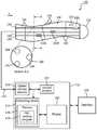
- FIG. 1is a block diagram showing an illustrative system for performing an interventional procedure in accordance with the present principles
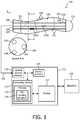
- FIG. 2is a block diagram showing an interventional instrument having sensing optical fibers and a parameter measuring fiber in accordance with the present principles
- FIG. 3is a block diagram showing an interventional instrument having sensing optical fibers and a parameter measuring fiber with windows opened to the external environment in accordance with the present principles
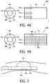
- FIG. 4Ais a diagram showing fiber sensors aligned to measure a parameter at a same location in accordance with the present principles
- FIG. 4Bis a diagram showing fiber sensors staggered to measure several parameters at a same location in accordance with the present principles
- FIG. 5is a diagram showing a stabilization device employed with optical sensors in accordance with one illustrative application.
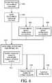
- FIG. 6is a flow diagram showing an illustrative interventional procedure in accordance with the present principles.
- Fiber-optic Bragg Gratingscan be incorporated directly into the body of an elongated instrument such as a guide wire or catheter without significantly changing the instrument mechanical properties, form factor or footprint.
- rapid multipoint and multiparameter measurements of segmental motion, voltage, temperature, and pressureare possible with the introduction of coatings or crystal materials (e.g., Bi 12 TiO 20 crystals for voltage sensing, Ni—Mn—Ga memory shape metal alloys for magnetic sensing, Zn metal vapor deposition for enhanced temperature sensing, etc).
- a FBG functionalized medical devicesuch as a guide wire, catheter, or other flexible elongated instrument is described that performs simultaneous measurements of motion, voltage, temperature, pressure or other parameters in a distributed fashion such as at an “effector” segment or other segment of the instrument, e.g., the distal 10 cm segment including the tip of a loop/lasso mapping catheter used in electrophysiology procedures. Segmental motion tracking may be performed along the length of the instrument and therefore motion compensation/gating of instrument imaging data or voltage/temperature/pressure measurements may be made more accurate.
- Tracking deformation of the “effector” segment of the instrumentmay be employed to measure a change in biological tissue response to the intervention, e.g., monitoring tissue-induced FBG strains in a loop catheter to estimate electromechanical synchrony or to estimate intervention impact on cardiac contractility.
- the present inventionwill be described in terms of medical instruments; however, the teachings of the present invention are much broader and are applicable to any instruments employed in tracking or analyzing complex biological or mechanical systems. It should also be understood that the illustrative example of the optical device may also include electronic components, depending on the application. The elements depicted in the FIGS. may be implemented in various combinations of hardware and provide functions which may be combined in a single element or multiple elements.
- processoror “controller” should not be construed to refer exclusively to hardware capable of executing software, and can implicitly include, without limitation, digital signal processor (“DSP”) hardware, read-only memory (“ROM”) for storing software, random access memory (“RAM”), and non-volatile storage.
- DSPdigital signal processor
- ROMread-only memory
- RAMrandom access memory
- embodiments of the present inventioncan take the form of a computer program product accessible from a computer-usable or computer-readable medium providing program code for use by or in connection with a computer or any instruction execution system.
- a computer-usable or computer readable mediumcan be any apparatus that may include, store, communicate, propagate, or transport the program for use by or in connection with the instruction execution system, apparatus, or device.
- the mediumcan be an electronic, magnetic, optical, electromagnetic, infrared, or semiconductor system (or apparatus or device) or a propagation medium.
- Examples of a computer-readable mediuminclude a semiconductor or solid state memory, magnetic tape, a removable computer diskette, a random access memory (RAM), a read-only memory (ROM), a rigid magnetic disk and an optical disk. Current examples of optical disks include compact disk-read only memory (CD-ROM), compact disk-read/write (CD-R/W) and DVD.
- Device 100may include a guide wire, catheter, or other flexible elongated instrument that permits any or all of simultaneous measurements, segmental motion tracking and/or tracking deformation.
- Simultaneous measurementsmay be made using device 100 for motion, voltage, temperature, pressure, color, strain, magnetism, position, biochemical state, etc. in a distributed fashion.
- multiple measurementsmay be made at an effector segment or any segment 101 of an instrument.
- the effector segmentmay include a distal end segment including a tip of a loop/lasso mapping catheter used in electrophysiology procedures, and more particularly, a distal end 10 cm segment.
- Device 100is also capable of segmental motion tracking along the length of the instrument itself. Therefore, FBG-derived compensation and correction of instrument imaging data or voltage/temperature/pressure measurements can be made at one or more segments 101 .
- the device 100may also track deformation of the effector segment of the instrument to measure a change in biological tissue responsive to an intervention procedure, e.g., monitoring tissue-induced FBG strains in a loop catheter to estimate electromechanical synchrony or to estimate intervention impact on cardiac contractility. In this way, deflection experienced by device 100 may be correlated to deformations of tissue surrounding the device 100 .
- an intervention proceduree.g., monitoring tissue-induced FBG strains in a loop catheter to estimate electromechanical synchrony or to estimate intervention impact on cardiac contractility.
- the device 100includes strain or other sensors 102 which are disposed over an elongated section of the device 100 .
- One sensor 102may be provided in each of three fibers 104 to form a sensor triplet at a given cross-section or axial location (x-direction) in this embodiment. Other numbers of fibers may also be employed.
- the device 100is preferably an elongated medical instrument for diagnosis, intervention, or therapy monitoring and may take the form of a catheter, guidewire, endoscope, etc. (with manual or automatic steering control for device navigation).
- the fibers 104are introduced into the body of the instrument 100 with a series of fiber Bragg gratings or other sensors 102 spatially distributed along its length and/or clustered in functional regions of the instrument, e.g., a distal segment including a tip.
- the sensors 102may form an array to collect data over a region.
- Each fiber 104may include one or more sensors 102 .
- the sensors 102may include uncoated FBGs for shape sensing, FBGs incorporating materials for temperature sensing (e.g. Zn metal vapor deposition), FBGs incorporating materials for voltage/magnetic field sensing (e.g. Bi 12 TiO 20 , Ni—Mn—Ga), and/or other FBGs incorporating materials for sensitivity to other biophysical parameters of interest (e.g., pH sensing, pCO 2 , etc.). Other optical or electronic sensors may also be employed.
- FBGs for shape sensinge.g. Zn metal vapor deposition
- FBGs incorporating materials for voltage/magnetic field sensinge.g. Bi 12 TiO 20 , Ni—Mn—Ga
- Other optical or electronic sensorsmay also be employed.
- Device 100may include an optical module 110 for sense fiber illumination and receiving fiber signals.
- the source of module 110may be at a proximate end portion of the device and carry light using a waveguide or at the distal end portion for direct illumination.
- the module 110includes a receiver function.
- An optical interrogation console 112may be employed for readout of multiplexed signals returning from FBGs in all fibers.
- a computing device 114may include a real-time FBG sensing program 116 for sensing fiber shape, mapping temperature-sensitive FBG wavelength shifts into temperature changes, mapping voltage/magnetic field sensitive FBG wavelength shifts into voltage/magnetic field characteristics, and/or mapping other custom FBG wavelength shifts into corresponding biophysical parameter measurements.
- the console 112is configured for real-time interaction and visual display of instrument location and spatially distributed measurements (e.g., FBG-derived biophysical measurements, endoscope-based video or other imaging data, catheter-based video or other imaging data).
- the device 100may optionally include low-cost conventional sensors 120 , e.g., electrodes for voltage sensing or may include a stabilizing/fixation mechanism 122 for holding a point on the sensing fiber fixed against a reference location of interest (e.g. a balloon with or without perforations to allow for flow past the fixation point).
- a stabilizing/fixation mechanism 122for holding a point on the sensing fiber fixed against a reference location of interest (e.g. a balloon with or without perforations to allow for flow past the fixation point).
- the system 150may optionally include a medical imaging system 130 to provide a more global visualization of the anatomy of interest and interventional field-of-view (e.g., CV-X-ray system for cardiac procedures, or ultrasound system for body interventions, etc.).
- the instrument 100may be employed in conjunction with imaging data acquired either pre-procedurally, intra-procedurally, or simultaneously with optical interrogation. Imaging and optical data recordings can be used in combination to improve the estimates of biophysical parameters, instrument characteristics, and tissue properties to make decisions about interventional procedure guidance and monitor therapy progress.
- System 150includes a data connection 152 to/from a sensor output (or FBG interrogation output) from sensors 102 a - c providing a read-out of fiber shape/additional biophysical parameters.
- the instrument data acquiredmay be carried on connection 152 , e.g., real-time video (e.g., from a video endoscope), real-time ultrasound (e.g., from an intracardiac echo, ICE catheter).
- An instrument therapy mechanism 154delivers, e.g., RF power for an RF ablation catheter, ultrasound (US) power delivery for a HIFU instrument, etc.
- the data connection 152 between the FBG-enabled instrument 100also provide information to/from the medical imaging system 130 .
- Feedback and control signalsmay be exchanged through connection 152 .
- instrument navigationmay be employed as feedback based on FBG interrogation to assist in guiding the instrument 100 .
- feedback or control signalsmay be employed for instrument therapy delivery based on FBG interrogation.
- System 150may include multiple processing or computing devices 114 for generating control signals, performing computations, generating video images, interpreting feedback, etc.
- processing of distributed FBG shape measurementspermits segment dependent respiratory, cardiac, or gross patient motion gating, correction of instruments, medical imaging system data, etc.
- cardiac motionmay dominate at sensor 102 c
- respiratory motionmay dominate at sensor 102 b
- a third segment 101reflects gross patient motion at sensor 102 a .
- Multiple fiberspermit feedback from all three segments.
- a usersuch as a surgeon or technician, can select specific segments from which to extract gating signals via graphical interaction on an instrument console 112 of system 150 .
- the signals from these regionscan then be used to gate or motion correct the actual measurements of interest to obtain motion-compensation video from a video endoscope, or motion-compensated ultrasound from an ICE catheter, or motion-corrected fluoroscopy from an X-ray imaging system, etc.
- processing of FBG shape measurementsmay be performed by processor 114 to track deformation of the “effector” segment of the instrument 100 and so monitor a change resulting from intervention, e.g., monitoring tissue-induced FBG strains in a loop catheter to estimate electromechanical synchrony or to estimate intervention impact on cardiac contractility.
- the usermay store data in memory 115 .
- Memorymay include programs (e.g., program 116 ).
- the program 116may be adapted to take measurements and control sensors (e.g., FBGs).
- a display 157may be provided for visualizing procedures and/or for interfacing with the console 112 and device 100 during a procedure.
- the usermay employ a user interface 159 to interact with the console 112 and/or the instrument 100 .
- the interface 159may include a keyboard, a mouse, a touch screen system, etc.
- an illustrative interventional medical device 200includes a shape sensing fiber(s) 202 in an elongated medical instrument 204 with segment specific motion correction for individual segments 201 or the device 200 as a whole.
- the elongated instrument 204may include low-cost sensors 208 such as electrodes for voltage mapping, miniature thermistors for temperature sensing, etc.
- the sensing fibers 202include a distribution of FBGs 210 a - c embedded within the instrument body. During a procedure, FBG-derived shape/motion data are visualized on a graphical display ( 157 , FIG.
- instrument locationshown as a registered overlay on top of pre-procedurally acquired imaging data or intra-procedurally acquired imaging data from a medical imaging system sharing a data connection with the FBG-enabled instrument.
- a clinicianis enabled to graphically select the segments or sub-segments of the instrument 200 to be used for separate respiratory motion gating (and/or compensation) 210 a , cardiac motion gating (and/or compensation) 210 b , gastro-intestinal (GI) motion (and/or compensation) 210 c , and gross patient motion (and/or compensation) 210 d , for example.
- the sensor positions and locationscan be predetermined or adjusted to provide spatially specific measurements concurrently from different information sources.
- a workstation or console 220takes the prescribed motion/gating signals from each of the segments or sub-segments, then computes and displays, in real-time, the motion corrected measurements of interest, e.g., gated/motion-corrected voltage measurements from an EP mapping catheter.
- Position tracking provided by the embedded sensing fiber 202permits for spatial mapping and multidimensional reconstruction of data acquired by the instrument 200 , e.g., video/image mapping/surface reconstruction in 3D, voltage/temperature mapping in 3D, etc.
- deformation measurements from the sensing fiber 202can be combined with conventional instrument measurements ( 208 ) to monitor responses to the intervention.
- a shape-sensing-enabled flexible loop catheter with conventional electrodes ( 208 ) for both voltage measurement and delivery of ablation energycan be positioned in contact with the ventricular wall during ablation and voltage measurement. Changes in deformation of the loop segment in contact with wall will reflect changes in synchrony and magnitude of myocardial motion, which is of clinical relevance in assessing response.
- the workstation or console 220can also take the position/motion signals from each of the segments or sub-segment to display, in real-time, a fused overlay of the FBG-enabled interventional device with imaging data acquired concurrently or pre-procedurally.
- Thisallows for visualization of the interventional device via FBG enabled position sensing which is especially useful for imaging modalities that do not permit direct visualization of the device itself.
- standard cathetersare poorly visible under ultrasound imaging or are completely invisible under magnetic resonance imaging.
- the use of FBG-enabled instrumentation in combination with imagingwould facilitate intervention guidance since the imaging modality would provide feedback about tissue/organ properties whereas FBG sensing would provide information about instrument properties.
- the instruments described hereinmay have many functional features and variations.
- the instrumentsmay include a working channel or lumen 215 to provide a way to by-pass fluids, to apply suction, to permit the movement of other tools and instruments, etc.
- an illustrative interventional medical device 300includes one or more shape sensing fibers 302 each with a single biophysical parameter sensing core and a contact/window 306 to an external environment 307 .
- the elongated instrument 304has FBG-based sensors for measurement of temperature, voltage, magnetic field, chemical concentration, etc. to achieve further miniaturization potential.
- FBG-based sensorsfor measurement of temperature, voltage, magnetic field, chemical concentration, etc. to achieve further miniaturization potential.
- a single optical fiber with a distribution of FBGs spaced along the length of interestis employed.
- the coatings used for consecutive FBGscan be interleaved so that a temperature sensitive FBG 308 is positioned beside a voltage sensitive FBG 310 , followed by a pressure sensitive FBG 312 in an alternating pattern.
- the pattern and distribution/spacing of these FBGscan be varied according to the instrument type and application.
- the biophysical parameter sensing fiber 302 ′is eccentrically positioned close to the outer perimeter of the instrument 300 is shown.
- a metallic or conductive ring 314is placed around the instrument 300 in contact with both the FBG temperature sensor 308 and the external environment to ensure coupling.
- windows 306 or 320 in the outer perimeter of the instrument at or near a location of FBGsmay be employed for exposure of the FBG sensor(s) to pressure conditions in the external environment (these windows 306 or 320 can either be open or thin-membrane covered holes). These windows 306 or 320 may be closable and controlled by an operator as needed.
- an illustrative interventional medical device 400is shown in cross-section on the left and with an illustrative side diagram on the right to demonstrate the present concepts.
- the device 400includes shape sensing fibers 402 in an elongated medical instrument 404 with multiple biophysical parameter sensing cores or sensors 406 which may include contacts or windows to an external environment to make measurements thereof. Aligned multiparameter sensing cores are depicted in FIG. 4A , while FIG. 4B shows staggered multiparameter sensing cores or sensors.
- Multi-core arrangements of biophysical parameter sensing fibers or sensors 406can be positioned around the shape sensing fibers 402 to permit for parameter sensing at multiple points around the instrument periphery. If the FBGs in these cores are aligned (as in FIG. 4A ) so that each FBG at the same axial section (at position P) senses the same biophysical parameter, e.g. temperature, the measurements can be averaged to obtain higher signal to noise (SNR) performance.
- SNRsignal to noise
- the cores or sensors 406can be staggered (as depicted in FIG. 4B ) so that at the same axial contact point (Q), each of the FBGs senses a different biophysical parameter, allowing for multi-parameter sensing at the same location along the instrument 400 .
- these multi-parameter measurementscan be used jointly to derive more accurate temperature, strain, etc. corrected estimates.
- the elongated instrumentmay be reconfigurable to permit customization of the positioning of FBG sensors or even the fiber density or position relative the periphery or other feature of the instrument.
- optical fibersmay be replaced with other signals carrying devices and that optical sensors may include non-optical sensors.
- additional mechanisms or featuresmay be employed to customize or increase the functionality of the instruments in accordance with the present principles.
- Any of the described embodimentsmay be employed together with a stabilization/mechanical fixation device 502 (e.g., based on balloons or other mechanical structures) for an instrument 500 (similar to those described as instruments 100 , 200 , 300 ) to obtain a reference location for measurements.
- a stabilization/mechanical fixation device 502e.g., based on balloons or other mechanical structures
- balloon deploymentmay be employed to fix a temperature-sensitive FBG 504 at an anatomical location 506 desired for reference temperature measurements far from a site of ablation therapy.
- Another mechanism that may be employed using FBGsincludes a feedback mechanism employed for feedback or control of navigation or therapy delivery based on multi-sensor distributed measurements (e.g., a temperature reference at a fixed point distant from an ablation site for monitoring and control of temperature elevation following energy delivery).
- the information collected at the siteis employed to provide information to the technician or surgeon to provide feedback on events occurring at the site (e.g., 506 ).
- the system 150 depicted in FIG. 1e.g., may be employed for collecting and using the feedback during a procedure.
- sensorsare preferably distributed such that deformation, vibration, or any other distortion mode induced in a segment of the instrument is measured to determine either a tissue response to the instrument during an interventional procedure, or feedback from the instrument about tissue-instrument interaction (e.g., haptic feedback during instrument navigation within a lumen).
- an interventional instrumentincluding an elongated flexible member having one or more sections, which may be segmented and disposed longitudinally. At least one optical fiber is disposed internally in the flexible member, and a plurality of optical sensors are coupled to the at least one optical fiber and distributed along a length of the flexible member such that the optical sensors are positioned to monitor separate parameters simultaneously along the flexible member to provide distributed sensing.
- the interventional instrumentis guided into a body to perform a medical procedure.
- a set of optical sensors associated with a plurality of optical fibersis aligned where an aligned set includes a sensor associated with each fiber such that the aligned set measures a same parameter at a same axial position along a length of the flexible member.
- a set of optical sensors associated with the plurality of optical fibersis staggered where a staggered set includes a sensor associated with each fiber such that the staggered set measures different parameters at a same axial position along a length of the flexible member.
- An array of sensorsmay be employed to map, monitor, apply therapy, etc. to a given area.
- datais concurrently gathered from a plurality of data sources by respective sensors. Testing or therapy is performed, or any other action is performed using the fiber optic interventional instrument.
- respective sensorsare positioned relatively, the relative position being determined to provide proximity to different data sources when the flexible member is located in a data gathering position in block 612 .
- segmental motion of two or more of the segmentsis measured to provide a more accurate positional orientation for the instrument.
- deformation of a segment of the instrumentis measured using distributed sensors to determine a tissue response to the instrument during an interventional procedure.
- fibers and sensor arraysmay be customized and repositioned to provide a flexible design to accommodate a given procedure.
- Clinical applicationsinclude, but are not limited to catheter-based navigation, mapping, and ablation for treatment of atrial fibrillation or ventricular arrhythmias (FBG-functionalized ablation catheter, pulmonary vein loop catheter, coronary sinus catheter, etc.), pulmonary venous contraction monitoring, cardiac resynchronization therapy and cardiac contractility/electromechanical synchrony assessment, cardiac filter device or balloon deployment, transcatheter valve replacement, and FBG-enabled endoscopy-based procedures (imaging, biopsy, ablation, NOTES, etc.) in cardiac, pulmonary, or body interventions.
- FBG-functionalized ablation catheter, pulmonary vein loop catheter, coronary sinus catheter, etc.pulmonary venous contraction monitoring
- cardiac resynchronization therapyand cardiac contractility/electromechanical synchrony assessment
- cardiac filter device or balloon deploymenttranscatheter valve replacement
- FBG-enabled endoscopy-based proceduresimaging, biopsy, ablation, NOTES, etc.
- Other applications and procedures where the present principles are applicablealso exist and are contemplated
Landscapes
- Health & Medical Sciences (AREA)
- Life Sciences & Earth Sciences (AREA)
- Surgery (AREA)
- Molecular Biology (AREA)
- General Health & Medical Sciences (AREA)
- Optics & Photonics (AREA)
- Engineering & Computer Science (AREA)
- Biomedical Technology (AREA)
- Heart & Thoracic Surgery (AREA)
- Medical Informatics (AREA)
- Nuclear Medicine, Radiotherapy & Molecular Imaging (AREA)
- Animal Behavior & Ethology (AREA)
- Pathology (AREA)
- Public Health (AREA)
- Veterinary Medicine (AREA)
- Physics & Mathematics (AREA)
- Biophysics (AREA)
- Radiology & Medical Imaging (AREA)
- Oral & Maxillofacial Surgery (AREA)
- Endoscopes (AREA)
- Measuring And Recording Apparatus For Diagnosis (AREA)
- Surgical Instruments (AREA)
- Length Measuring Devices By Optical Means (AREA)
Abstract
Description
Claims (28)
Priority Applications (1)
| Application Number | Priority Date | Filing Date | Title |
|---|---|---|---|
| US13/501,101US10610085B2 (en) | 2009-10-23 | 2010-08-26 | Optical sensing-enabled interventional instruments for rapid distributed measurements of biophysical parameters |
Applications Claiming Priority (3)
| Application Number | Priority Date | Filing Date | Title |
|---|---|---|---|
| US25431709P | 2009-10-23 | 2009-10-23 | |
| US13/501,101US10610085B2 (en) | 2009-10-23 | 2010-08-26 | Optical sensing-enabled interventional instruments for rapid distributed measurements of biophysical parameters |
| PCT/IB2010/053845WO2011048509A1 (en) | 2009-10-23 | 2010-08-26 | Optical sensing - enabled interventional instruments for rapid distributed measurements of biophysical parameters |
Publications (2)
| Publication Number | Publication Date |
|---|---|
| US20120197097A1 US20120197097A1 (en) | 2012-08-02 |
| US10610085B2true US10610085B2 (en) | 2020-04-07 |
Family
ID=43063556
Family Applications (1)
| Application Number | Title | Priority Date | Filing Date |
|---|---|---|---|
| US13/501,101Expired - Fee RelatedUS10610085B2 (en) | 2009-10-23 | 2010-08-26 | Optical sensing-enabled interventional instruments for rapid distributed measurements of biophysical parameters |
Country Status (6)
| Country | Link |
|---|---|
| US (1) | US10610085B2 (en) |
| EP (2) | EP3266383A1 (en) |
| JP (2) | JP5952736B2 (en) |
| CN (1) | CN102573691B (en) |
| RU (1) | RU2577509C2 (en) |
| WO (1) | WO2011048509A1 (en) |
Families Citing this family (65)
| Publication number | Priority date | Publication date | Assignee | Title |
|---|---|---|---|---|
| CN103607949B (en)* | 2011-06-10 | 2016-01-20 | 皇家飞利浦有限公司 | Utilize the dynamic constrained that optic shape senses |
| DE102011081546B4 (en)* | 2011-08-25 | 2013-07-04 | Siemens Ag | Apparatus and method for minimally invasive length measurement within a hollow organ |
| JP5618422B2 (en)* | 2011-09-02 | 2014-11-05 | 飛島建設株式会社 | FBG optical fiber sensor type strain sensor |
| JP6223977B2 (en)* | 2011-09-02 | 2017-11-01 | コーニンクレッカ フィリップス エヌ ヴェKoninklijke Philips N.V. | Medical device insertion and removal information using distributed optical fiber temperature sensing |
| US10463259B2 (en) | 2011-10-28 | 2019-11-05 | Three Rivers Cardiovascular Systems Inc. | System and apparatus comprising a multi-sensor catheter for right heart and pulmonary artery catheterization |
| US20140243688A1 (en) | 2011-10-28 | 2014-08-28 | Three Rivers Cardiovascular Systems Inc. | Fluid temperature and flow sensor apparatus and system for cardiovascular and other medical applications |
| US20140257139A1 (en)* | 2011-11-16 | 2014-09-11 | Commonwealth Scientific And Industrial Research Organisation | Optical sensing device |
| EP2740399A4 (en)* | 2012-03-22 | 2015-10-14 | Olympus Medical Systems Corp | MEASURING PROBE, BIO-OPTICAL MEASURING APPARATUS AND BIO-OPTICAL MEASURING SYSTEM |
| CN104203085A (en)* | 2012-03-29 | 2014-12-10 | 皇家飞利浦有限公司 | Temperature control mechanisms for stable shape sensing |
| US20130274618A1 (en)* | 2012-04-17 | 2013-10-17 | Boston Scientific Scimed, Inc. | Guidewire system for use in transcatheter aortic valve implantation procedures |
| WO2013177577A2 (en)* | 2012-05-25 | 2013-11-28 | Eberle Michael J | Optical fiber pressure sensor |
| EP2858553A1 (en)* | 2012-06-08 | 2015-04-15 | Koninklijke Philips N.V. | Distributed sensing device for referencing of physiological features |
| JP6574378B2 (en)* | 2012-08-04 | 2019-09-11 | コーニンクレッカ フィリップス エヌ ヴェKoninklijke Philips N.V. | Quantifying probe deflection to improve catheter identification |
| CN104470575B (en) | 2012-08-14 | 2017-06-06 | 直观外科手术操作公司 | Systems and methods for configuring components in a minimally invasive device |
| RU2666580C2 (en)* | 2012-10-02 | 2018-09-11 | Конинклейке Филипс Н.В. | Display of volume using optical shape sensors |
| EP2932211B1 (en) | 2012-12-14 | 2024-11-20 | Koninklijke Philips N.V. | Wrist-worn device for sensing ambient light intensity |
| JP2016506270A (en)* | 2012-12-21 | 2016-03-03 | デイビッド アンダーソン, | Multi-sensor device |
| US20140180168A1 (en)* | 2012-12-21 | 2014-06-26 | Volcano Corporation | Guidewire with touch sensor |
| BR112015019171A2 (en)* | 2013-02-14 | 2017-07-18 | Koninklijke Philips Nv | intervention system, intervention method, and computer program |
| EP2996604B1 (en)* | 2013-03-26 | 2021-03-10 | Koninklijke Philips N.V. | System for minimizing twist for optical shape sensing enabled instruments |
| US11266466B2 (en) | 2013-07-29 | 2022-03-08 | Intuitive Surgical Operations, Inc. | Shape sensor systems with redundant sensing |
| WO2015032676A1 (en)* | 2013-09-06 | 2015-03-12 | Koninklijke Philips N.V. | Navigation system |
| WO2015051003A1 (en) | 2013-10-04 | 2015-04-09 | Vascular Imaging Corporation | Imaging techniques using an imaging guidewire |
| CN105683730B (en) | 2013-10-25 | 2019-01-11 | 光纳株式会社 | Optical fiber biodiagnostic sensor system and blood vessel insertion type distributed pressure measuring device |
| US10537255B2 (en) | 2013-11-21 | 2020-01-21 | Phyzhon Health Inc. | Optical fiber pressure sensor |
| JP6188564B2 (en)* | 2013-12-19 | 2017-08-30 | オリンパス株式会社 | Insertion device |
| JP2015134001A (en)* | 2014-01-16 | 2015-07-27 | ニプロ株式会社 | Measuring device using optical fiber |
| EP3110360B1 (en) | 2014-02-27 | 2019-04-10 | Koninklijke Philips N.V. | System for performing a therapeutic procedure |
| JP6659560B2 (en)* | 2014-02-27 | 2020-03-04 | コーニンクレッカ フィリップス エヌ ヴェKoninklijke Philips N.V. | Registration device for intervention procedure and its operation method |
| US20150272698A1 (en)* | 2014-03-31 | 2015-10-01 | Regents Of The University Of Minnesota | Navigation tools using shape sensing technology |
| CA2954959C (en) | 2014-07-13 | 2018-03-20 | Three Rivers Cardiovascular Systems Inc. | System and apparatus comprising a multisensor guidewire for use in interventional cardiology |
| WO2016070099A1 (en)* | 2014-10-31 | 2016-05-06 | Lake Region Medical, Inc. | Membrane-free fiber bragg grating pressure sensing guidewire |
| US10548489B2 (en) | 2014-10-31 | 2020-02-04 | Lake Region Medical, Inc. | Fiber Bragg grating multi-point pressure sensing guidewire with birefringent component |
| JP6618254B2 (en)* | 2014-12-24 | 2019-12-11 | 日本ライフライン株式会社 | Temperature measuring device and catheter system |
| CN107110631B (en)* | 2015-02-02 | 2020-01-31 | 西安大略大学 | system for tracking objects |
| US11272847B2 (en) | 2016-10-14 | 2022-03-15 | Hemocath Ltd. | System and apparatus comprising a multi-sensor catheter for right heart and pulmonary artery catheterization |
| US12178550B2 (en) | 2016-12-09 | 2024-12-31 | Intuitive Surgical Operations, Inc. | System and method for distributed heat flux sensing of body tissue |
| US11517184B2 (en) | 2017-02-01 | 2022-12-06 | Intuitive Surgical Operations, Inc. | Systems and methods of registration for image-guided procedures |
| US20190380762A1 (en)* | 2017-02-21 | 2019-12-19 | St. Jude Medical, Cardiology Division, Inc. | Blood Vessel Isolation Ablation Device |
| EP3524953A1 (en)* | 2018-02-07 | 2019-08-14 | Koninklijke Philips N.V. | Distributed intravascular fiber bragg pressure sensor |
| US11801362B2 (en)* | 2018-05-21 | 2023-10-31 | The Texas A&M University System | Surgical cannulas and related methods |
| RU2760994C2 (en)* | 2018-08-01 | 2021-12-02 | Юрий Викторович Бабченко | Device for measuring heart work parameters |
| WO2020033318A1 (en) | 2018-08-07 | 2020-02-13 | Auris Health, Inc. | Combining strain-based shape sensing with catheter control |
| CN109223060A (en)* | 2018-08-23 | 2019-01-18 | 荆门市第二人民医院 | The control system and control method of auxiliary device in a kind of surgical operation |
| US11134851B2 (en)* | 2018-12-14 | 2021-10-05 | Viavi Solutions Inc. | Sensor device |
| GB2580164A (en)* | 2018-12-21 | 2020-07-15 | Imperial College Sci Tech & Medicine | A sensor |
| WO2021062527A1 (en) | 2019-09-30 | 2021-04-08 | Hemocath Ltd. | Multi-sensor catheter for right heart and pulmonary artery catheterization |
| US11474310B2 (en) | 2020-02-28 | 2022-10-18 | Bard Access Systems, Inc. | Optical connection systems and methods thereof |
| CN215461207U (en) | 2020-02-28 | 2022-01-11 | 巴德阿克塞斯系统股份有限公司 | Catheter and medical instrument monitoring system |
| CN113332561A (en) | 2020-03-03 | 2021-09-03 | 巴德阿克塞斯系统股份有限公司 | System and method for optical shape sensing and electrical signal conduction |
| WO2021186330A1 (en)* | 2020-03-16 | 2021-09-23 | St. Jude Medical International Holding S.À.R.L. | System and method for optical sensor reference frame alignment |
| WO2021202589A1 (en) | 2020-03-30 | 2021-10-07 | Bard Access Systems, Inc. | Optical and electrical diagnostic systems and methods thereof |
| CN111839442B (en)* | 2020-06-08 | 2021-09-07 | 北京交通大学 | A fiber grating sensor and flexible ureteroscope |
| CN112237423A (en)* | 2020-08-13 | 2021-01-19 | 张海军 | Intervention type weak magnetic and pressure sensing system |
| EP3971519A1 (en)* | 2020-09-16 | 2022-03-23 | Koninklijke Philips N.V. | Method of and system for representing shape of an optical fiber sensor |
| CN114344514A (en) | 2020-10-13 | 2022-04-15 | 巴德阿克塞斯系统股份有限公司 | Disinfection enclosure for fiber optic connectors and method thereof |
| CN114518075A (en) | 2020-11-18 | 2022-05-20 | 巴德阿克塞斯系统股份有限公司 | fiber optic stylet holder |
| WO2022115624A1 (en) | 2020-11-24 | 2022-06-02 | Bard Access Systems, Inc. | Steerable fiber optic shape sensing enabled elongated medical instrument |
| US12318149B2 (en) | 2022-03-08 | 2025-06-03 | Bard Access Systems, Inc. | Medical shape sensing devices and systems |
| US12426956B2 (en) | 2022-03-16 | 2025-09-30 | Bard Access Systems, Inc. | Medical system and method for monitoring medical device insertion and illumination patterns |
| US12089815B2 (en)* | 2022-03-17 | 2024-09-17 | Bard Access Systems, Inc. | Fiber optic medical systems and devices with atraumatic tip |
| WO2024233657A1 (en)* | 2023-05-09 | 2024-11-14 | Gyrus Acmi, Inc. D/B/A Olympus Surgical Technologies America | Fiber bragg grating for endoscopes |
| WO2024241247A1 (en)* | 2023-05-25 | 2024-11-28 | Medtronic Navigation, Inc. | Systems and methods for determining one or more phases of anatomical movement |
| WO2025111486A1 (en)* | 2023-11-22 | 2025-05-30 | Gyrus Acmi, Inc. D/B/A Olympus Surgical Technologies America | Endoscope with navigation capability |
| CN117958757B (en)* | 2024-02-18 | 2024-12-10 | 天津大学 | An intrusive tactile sensor and application method |
Citations (35)
| Publication number | Priority date | Publication date | Assignee | Title |
|---|---|---|---|---|
| WO1991018306A2 (en) | 1990-05-22 | 1991-11-28 | Optex Biomedical, Inc. | Optical probe |
| US5195963A (en) | 1990-02-09 | 1993-03-23 | Minnesota Mining And Manufacturing Company | Method and system for monitoring of blood constituents in vivo |
| JPH07270261A (en) | 1994-03-31 | 1995-10-20 | Olympus Optical Co Ltd | Contact force and tactile sensor using piezoelectric vibration having three-terminal structure |
| US5493113A (en) | 1994-11-29 | 1996-02-20 | United Technologies Corporation | Highly sensitive optical fiber cavity coating removal detection |
| JPH08182665A (en) | 1994-12-28 | 1996-07-16 | Terumo Corp | Blood analysis object measuring device |
| US6120457A (en)* | 1997-07-02 | 2000-09-19 | Johnson & Johnson Professional, Inc. | In vivo zeroing of catheter pressure sensor |
| WO2001013060A1 (en) | 1999-08-13 | 2001-02-22 | Advanced Sensor Technologies Llc | Probe position sensing system for use in a coordinate measuring machine |
| US6256090B1 (en) | 1997-07-31 | 2001-07-03 | University Of Maryland | Method and apparatus for determining the shape of a flexible body |
| US6285806B1 (en) | 1998-05-31 | 2001-09-04 | The United States Of America As Represented By The Secretary Of The Navy | Coherent reflectometric fiber Bragg grating sensor array |
| US6315712B1 (en) | 1998-10-27 | 2001-11-13 | Tokendo (Sarl) | Video endoscopic probe with a distal color CCD sensor |
| US20020041723A1 (en)* | 2000-09-07 | 2002-04-11 | Erlend Ronnekleiv | Multi-parameter fiber optic probes |
| US20020052546A1 (en) | 2000-10-31 | 2002-05-02 | Northern Digital, Inc. | Flexible instrument with optical sensors |
| EP1319364A2 (en) | 2001-12-14 | 2003-06-18 | Biosense Webster, Inc. | Multiple electrode mapping catheter with location sensor |
| WO2003094723A1 (en) | 2002-05-09 | 2003-11-20 | Given Imaging Ltd. | System and method for in vivo sensing |
| US6659957B1 (en)* | 1998-03-05 | 2003-12-09 | Gil M. Vardi | Optical-acoustic imaging device |
| US20040165810A1 (en) | 2003-02-20 | 2004-08-26 | Fuji Photo Optical Co., Ltd. | Device for detecting three-dimensional shapes of elongated flexible body |
| US6869430B2 (en) | 2000-03-31 | 2005-03-22 | Rita Medical Systems, Inc. | Tissue biopsy and treatment apparatus and method |
| US6898337B2 (en) | 2003-03-19 | 2005-05-24 | Luna Innovations, Incorporated | Fiber-optic apparatus and method for making simultaneous multiple parameter measurements |
| US20060013523A1 (en) | 2004-07-16 | 2006-01-19 | Luna Innovations Incorporated | Fiber optic position and shape sensing device and method relating thereto |
| JP2006043449A (en) | 2004-07-08 | 2006-02-16 | Pentax Corp | Endoscope system |
| JP2007044412A (en) | 2005-08-12 | 2007-02-22 | Pentax Corp | Endoscope insertion shape detection probe |
| US20070075225A1 (en)* | 2005-09-30 | 2007-04-05 | General Electric Company | Fiber optic sensing device and method of making and operating the same |
| US20070109778A1 (en) | 2005-11-11 | 2007-05-17 | Coretronic Corporation | Positioning device for a projection apparatus |
| US20070265503A1 (en) | 2006-03-22 | 2007-11-15 | Hansen Medical, Inc. | Fiber optic instrument sensing system |
| JP2007322918A (en) | 2006-06-02 | 2007-12-13 | Olympus Corp | Endoscopic device |
| CN101099657A (en) | 2007-07-13 | 2008-01-09 | 上海大学 | Spatial shape detection device and method for slender flexible rod |
| JP2008173397A (en) | 2007-01-22 | 2008-07-31 | Olympus Corp | Endoscope system |
| US7433552B2 (en) | 2005-12-22 | 2008-10-07 | Palo Alto Research Center Incorporated | Obtaining analyte information |
| US20080255629A1 (en)* | 2004-11-01 | 2008-10-16 | Proteus Biomedical, Inc. | Cardiac Motion Characterization by Strain Measurement |
| US20090076476A1 (en)* | 2007-08-15 | 2009-03-19 | Hansen Medical, Inc. | Systems and methods employing force sensing for mapping intra-body tissue |
| WO2009049038A1 (en) | 2007-10-11 | 2009-04-16 | Tufts University | Systems, devices, and methods employing fiber optic shape tracking |
| US7528860B2 (en) | 2005-04-29 | 2009-05-05 | Hewlett-Packard Development Company, L.P. | Method and system for videoconferencing between parties at N sites |
| US20110090486A1 (en) | 2009-07-15 | 2011-04-21 | Hansen Medical, Inc. | Fiber shape sensing systems and methods |
| US8306592B2 (en) | 2003-12-19 | 2012-11-06 | Olympus Corporation | Capsule medical device |
| US8961436B2 (en) | 2005-03-04 | 2015-02-24 | St. Jude Medical Luxembourg Holding S.á.r.l. | Medical apparatus system having optical fiber load sensing capability |
Family Cites Families (7)
| Publication number | Priority date | Publication date | Assignee | Title |
|---|---|---|---|---|
| JPS6260571A (en)* | 1985-09-12 | 1987-03-17 | アロカ株式会社 | Fiber applicator for endoscopic treatment |
| RU2116044C1 (en)* | 1996-04-02 | 1998-07-27 | Геннадий Борисович Яцевич | Panoramic light fiberscope |
| US5864641A (en)* | 1997-04-11 | 1999-01-26 | F&S, Inc. | Optical fiber long period sensor having a reactive coating |
| RU2208375C2 (en)* | 2001-07-17 | 2003-07-20 | Общество с ограниченной ответственностью "ЭФА-МВТ" | Videolaparoscope |
| JP4520161B2 (en)* | 2004-01-08 | 2010-08-04 | オリンパス株式会社 | Capsule medical device |
| JP4594616B2 (en)* | 2003-12-19 | 2010-12-08 | オリンパス株式会社 | Capsule medical system |
| US8554024B2 (en)* | 2006-10-25 | 2013-10-08 | Lxdata Inc. | Tilted grating sensor |
- 2010
- 2010-08-26USUS13/501,101patent/US10610085B2/ennot_activeExpired - Fee Related
- 2010-08-26EPEP17183272.8Apatent/EP3266383A1/ennot_activeWithdrawn
- 2010-08-26EPEP10760016Apatent/EP2490612A1/ennot_activeWithdrawn
- 2010-08-26WOPCT/IB2010/053845patent/WO2011048509A1/enactiveApplication Filing
- 2010-08-26CNCN201080047765.0Apatent/CN102573691B/ennot_activeExpired - Fee Related
- 2010-08-26JPJP2012534795Apatent/JP5952736B2/ennot_activeExpired - Fee Related
- 2010-08-26RURU2012121174/14Apatent/RU2577509C2/ennot_activeIP Right Cessation
- 2015
- 2015-03-13JPJP2015051145Apatent/JP6157526B2/ennot_activeExpired - Fee Related
Patent Citations (46)
| Publication number | Priority date | Publication date | Assignee | Title |
|---|---|---|---|---|
| US5195963A (en) | 1990-02-09 | 1993-03-23 | Minnesota Mining And Manufacturing Company | Method and system for monitoring of blood constituents in vivo |
| WO1991018306A2 (en) | 1990-05-22 | 1991-11-28 | Optex Biomedical, Inc. | Optical probe |
| US5124130A (en) | 1990-05-22 | 1992-06-23 | Optex Biomedical, Inc. | Optical probe |
| US5397411A (en) | 1990-05-22 | 1995-03-14 | Optex Biomedical, Inc. | Method for making optical probe |
| JPH07270261A (en) | 1994-03-31 | 1995-10-20 | Olympus Optical Co Ltd | Contact force and tactile sensor using piezoelectric vibration having three-terminal structure |
| US5493113A (en) | 1994-11-29 | 1996-02-20 | United Technologies Corporation | Highly sensitive optical fiber cavity coating removal detection |
| JPH08182665A (en) | 1994-12-28 | 1996-07-16 | Terumo Corp | Blood analysis object measuring device |
| JP3507161B2 (en) | 1994-12-28 | 2004-03-15 | テルモ株式会社 | Blood analyte measuring device |
| US6120457A (en)* | 1997-07-02 | 2000-09-19 | Johnson & Johnson Professional, Inc. | In vivo zeroing of catheter pressure sensor |
| US6256090B1 (en) | 1997-07-31 | 2001-07-03 | University Of Maryland | Method and apparatus for determining the shape of a flexible body |
| US6659957B1 (en)* | 1998-03-05 | 2003-12-09 | Gil M. Vardi | Optical-acoustic imaging device |
| US6285806B1 (en) | 1998-05-31 | 2001-09-04 | The United States Of America As Represented By The Secretary Of The Navy | Coherent reflectometric fiber Bragg grating sensor array |
| US6315712B1 (en) | 1998-10-27 | 2001-11-13 | Tokendo (Sarl) | Video endoscopic probe with a distal color CCD sensor |
| WO2001013060A1 (en) | 1999-08-13 | 2001-02-22 | Advanced Sensor Technologies Llc | Probe position sensing system for use in a coordinate measuring machine |
| US6471710B1 (en) | 1999-08-13 | 2002-10-29 | Advanced Sensor Technology, Llc | Probe position sensing system and method of employment of same |
| US6869430B2 (en) | 2000-03-31 | 2005-03-22 | Rita Medical Systems, Inc. | Tissue biopsy and treatment apparatus and method |
| US20020041723A1 (en)* | 2000-09-07 | 2002-04-11 | Erlend Ronnekleiv | Multi-parameter fiber optic probes |
| US20020052546A1 (en) | 2000-10-31 | 2002-05-02 | Northern Digital, Inc. | Flexible instrument with optical sensors |
| EP1319364A2 (en) | 2001-12-14 | 2003-06-18 | Biosense Webster, Inc. | Multiple electrode mapping catheter with location sensor |
| US6748255B2 (en) | 2001-12-14 | 2004-06-08 | Biosense Webster, Inc. | Basket catheter with multiple location sensors |
| WO2003094723A1 (en) | 2002-05-09 | 2003-11-20 | Given Imaging Ltd. | System and method for in vivo sensing |
| US20050075555A1 (en) | 2002-05-09 | 2005-04-07 | Arkady Glukhovsky | System and method for in vivo sensing |
| US20040165810A1 (en) | 2003-02-20 | 2004-08-26 | Fuji Photo Optical Co., Ltd. | Device for detecting three-dimensional shapes of elongated flexible body |
| US6868195B2 (en) | 2003-02-20 | 2005-03-15 | Fuji Photo Optical Co., Ltd. | Device for detecting three-dimensional shapes of elongated flexible body |
| US6898337B2 (en) | 2003-03-19 | 2005-05-24 | Luna Innovations, Incorporated | Fiber-optic apparatus and method for making simultaneous multiple parameter measurements |
| US8306592B2 (en) | 2003-12-19 | 2012-11-06 | Olympus Corporation | Capsule medical device |
| JP2006043449A (en) | 2004-07-08 | 2006-02-16 | Pentax Corp | Endoscope system |
| US20060013523A1 (en) | 2004-07-16 | 2006-01-19 | Luna Innovations Incorporated | Fiber optic position and shape sensing device and method relating thereto |
| US20080255629A1 (en)* | 2004-11-01 | 2008-10-16 | Proteus Biomedical, Inc. | Cardiac Motion Characterization by Strain Measurement |
| US9907618B2 (en) | 2005-03-04 | 2018-03-06 | St Jude Medical International Holding S.À R.L. | Medical apparatus system having optical fiber sensing capability |
| US8961436B2 (en) | 2005-03-04 | 2015-02-24 | St. Jude Medical Luxembourg Holding S.á.r.l. | Medical apparatus system having optical fiber load sensing capability |
| US7528860B2 (en) | 2005-04-29 | 2009-05-05 | Hewlett-Packard Development Company, L.P. | Method and system for videoconferencing between parties at N sites |
| JP2007044412A (en) | 2005-08-12 | 2007-02-22 | Pentax Corp | Endoscope insertion shape detection probe |
| US7228017B2 (en) | 2005-09-30 | 2007-06-05 | General Electric Company | Fiber optic sensing device and method of making and operating the same |
| US20070075225A1 (en)* | 2005-09-30 | 2007-04-05 | General Electric Company | Fiber optic sensing device and method of making and operating the same |
| US20070109778A1 (en) | 2005-11-11 | 2007-05-17 | Coretronic Corporation | Positioning device for a projection apparatus |
| US7433552B2 (en) | 2005-12-22 | 2008-10-07 | Palo Alto Research Center Incorporated | Obtaining analyte information |
| US20070265503A1 (en) | 2006-03-22 | 2007-11-15 | Hansen Medical, Inc. | Fiber optic instrument sensing system |
| US20130012809A1 (en) | 2006-03-22 | 2013-01-10 | Koninklijke Philips Electronics N.V. | System and method for sensing shape of elongated instrument |
| JP2007322918A (en) | 2006-06-02 | 2007-12-13 | Olympus Corp | Endoscopic device |
| JP2008173397A (en) | 2007-01-22 | 2008-07-31 | Olympus Corp | Endoscope system |
| CN101099657A (en) | 2007-07-13 | 2008-01-09 | 上海大学 | Spatial shape detection device and method for slender flexible rod |
| US20090076476A1 (en)* | 2007-08-15 | 2009-03-19 | Hansen Medical, Inc. | Systems and methods employing force sensing for mapping intra-body tissue |
| WO2009049038A1 (en) | 2007-10-11 | 2009-04-16 | Tufts University | Systems, devices, and methods employing fiber optic shape tracking |
| US20110172519A1 (en)* | 2007-10-11 | 2011-07-14 | Tufts University | Systems, devices and methods employing fiber optic shape tracking |
| US20110090486A1 (en) | 2009-07-15 | 2011-04-21 | Hansen Medical, Inc. | Fiber shape sensing systems and methods |
Non-Patent Citations (7)
| Title |
|---|
| Ambrosino, C. et al., "Novel Magnetic Sensor Based on Fiber Bragg Grating and Magnetic Shape Memory Alloys," 1st International Conference on Sensing Technology Nov. 21-23, Palmerston North, New Zealand, 350-354 (2005). |
| Fernandez, F. et al., "Multi-component force sensor based on multiplexed fibre Bragg grating strain sensors; Multi-component force sensor based on multiplexed FBG strain sensors", Meausrement Science and Technology, Jul. 1, 2001 IOP, Bristol, GB, vol. 12, Nr: 7, p. 810-813. |
| Kyuma, K. et al. "Fiber-optic current and voltage sensors using a Bi12GeO20 single crystal," J. Lightwave Technol. LT-1, 93-97 (1983). |
| Men et al. "Intelligent multiparameter sensing with fiber Bragg gratings." Appl. Phys. Lett. 93, 071110 (2008). (Year: 2008).* |
| Norimatsu, M. et al. "Bi12SiO20 crystal application for voltage sensor in optical fibers," Ferroelectrics 75, 189-196 (1987). |
| Rose, A.H. et al., "Optical fiber voltage sensors for broad temperature ranges," in Fiber Optic Components and Reliability, P.M. Kopera and D. K. Paul, eds., Proc. SPIE 1580, 95-103 (1992). |
| Zhang, L. et al., "On SDM/WDM FBG Sensor Net for Shape Detection of Endoscope", Mechatronics and Automation, 2005 IEEE Intenational Conference Niagara Falls, ON Canada Jul. 29-Aug. 1, 2005, Abstract. |
Also Published As
| Publication number | Publication date |
|---|---|
| JP6157526B2 (en) | 2017-07-05 |
| JP2013508058A (en) | 2013-03-07 |
| EP2490612A1 (en) | 2012-08-29 |
| RU2577509C2 (en) | 2016-03-20 |
| EP3266383A1 (en) | 2018-01-10 |
| CN102573691B (en) | 2016-02-24 |
| WO2011048509A1 (en) | 2011-04-28 |
| JP5952736B2 (en) | 2016-07-13 |
| JP2015154938A (en) | 2015-08-27 |
| CN102573691A (en) | 2012-07-11 |
| RU2012121174A (en) | 2013-11-27 |
| US20120197097A1 (en) | 2012-08-02 |
Similar Documents
| Publication | Publication Date | Title |
|---|---|---|
| US10610085B2 (en) | Optical sensing-enabled interventional instruments for rapid distributed measurements of biophysical parameters | |
| EP2608720B1 (en) | Mapping system for medical procedures | |
| US11547489B2 (en) | Shape sensing of multiple over-the-wire devices | |
| US12349984B2 (en) | System, method, and apparatus for improved confirm of an anatomical position of a medical instrument | |
| CN104349715B (en) | Distributed sensing device for reference to physiological characteristics | |
| JP5575431B2 (en) | Single axis sensor on flexible backbone | |
| JP6568084B2 (en) | Robot control to image devices using optical shape detection | |
| US20130324833A1 (en) | Non-rigid-body morphing of vessel image using intravascular device shape | |
| JP6706576B2 (en) | Shape-Sensitive Robotic Ultrasound for Minimally Invasive Interventions | |
| JP2017537698A (en) | Automatic tracking and registration of ultrasonic probes using optical shape detection without tip fixation | |
| JP2013534433A (en) | Optical fiber shape reconstruction | |
| WO2013030749A2 (en) | Medical device insertion and exit information using distributed fiber optic temperature sensing | |
| US20140243687A1 (en) | Shape sensing devices for real-time mechanical function assessment of an internal organ | |
| JP2017500935A5 (en) |
Legal Events
| Date | Code | Title | Description |
|---|---|---|---|
| AS | Assignment | Owner name:KONINKLIJKE PHILIPS ELECTRONICS N V, NETHERLANDS Free format text:ASSIGNMENT OF ASSIGNORS INTEREST;ASSIGNORS:CHAN, RAYMOND;BARLEY, MAYA ELLA;DESJARDINS, ADRIEN EMMANUEL;AND OTHERS;SIGNING DATES FROM 20100825 TO 20100913;REEL/FRAME:028015/0980 | |
| STPP | Information on status: patent application and granting procedure in general | Free format text:NON FINAL ACTION MAILED | |
| STPP | Information on status: patent application and granting procedure in general | Free format text:RESPONSE TO NON-FINAL OFFICE ACTION ENTERED AND FORWARDED TO EXAMINER | |
| STPP | Information on status: patent application and granting procedure in general | Free format text:RESPONSE TO NON-FINAL OFFICE ACTION ENTERED AND FORWARDED TO EXAMINER | |
| STPP | Information on status: patent application and granting procedure in general | Free format text:NOTICE OF ALLOWANCE MAILED -- APPLICATION RECEIVED IN OFFICE OF PUBLICATIONS | |
| ZAAA | Notice of allowance and fees due | Free format text:ORIGINAL CODE: NOA | |
| ZAAB | Notice of allowance mailed | Free format text:ORIGINAL CODE: MN/=. | |
| STPP | Information on status: patent application and granting procedure in general | Free format text:PUBLICATIONS -- ISSUE FEE PAYMENT RECEIVED | |
| STCF | Information on status: patent grant | Free format text:PATENTED CASE | |
| FEPP | Fee payment procedure | Free format text:MAINTENANCE FEE REMINDER MAILED (ORIGINAL EVENT CODE: REM.); ENTITY STATUS OF PATENT OWNER: LARGE ENTITY | |
| LAPS | Lapse for failure to pay maintenance fees | Free format text:PATENT EXPIRED FOR FAILURE TO PAY MAINTENANCE FEES (ORIGINAL EVENT CODE: EXP.); ENTITY STATUS OF PATENT OWNER: LARGE ENTITY | |
| STCH | Information on status: patent discontinuation | Free format text:PATENT EXPIRED DUE TO NONPAYMENT OF MAINTENANCE FEES UNDER 37 CFR 1.362 | |
| FP | Lapsed due to failure to pay maintenance fee | Effective date:20240407 |