US10610074B2 - Sensor cleaning apparatus - Google Patents
Sensor cleaning apparatusDownload PDFInfo
- Publication number
- US10610074B2 US10610074B2US15/641,406US201715641406AUS10610074B2US 10610074 B2US10610074 B2US 10610074B2US 201715641406 AUS201715641406 AUS 201715641406AUS 10610074 B2US10610074 B2US 10610074B2
- Authority
- US
- United States
- Prior art keywords
- assembly
- sensor
- axis
- blower
- sensor window
- Prior art date
- Legal status (The legal status is an assumption and is not a legal conclusion. Google has not performed a legal analysis and makes no representation as to the accuracy of the status listed.)
- Active, expires
Links
- 238000004140cleaningMethods0.000titledescription4
- 230000037361pathwayEffects0.000description4
- 239000007787solidSubstances0.000description3
- 238000001514detection methodMethods0.000description2
- 229920005372Plexiglas®Polymers0.000description1
- 230000004888barrier functionEffects0.000description1
- 230000005540biological transmissionEffects0.000description1
- 239000000428dustSubstances0.000description1
- 239000002657fibrous materialSubstances0.000description1
- 239000011521glassSubstances0.000description1
- -1laminatedSubstances0.000description1
- 238000005259measurementMethods0.000description1
- 238000012986modificationMethods0.000description1
- 230000004048modificationEffects0.000description1
- 239000002245particleSubstances0.000description1
- 239000004033plasticSubstances0.000description1
- 229920003023plasticPolymers0.000description1
- 239000004417polycarbonateSubstances0.000description1
- 229920000515polycarbonatePolymers0.000description1
- 239000004926polymethyl methacrylateSubstances0.000description1
- 239000005341toughened glassSubstances0.000description1
- 239000012780transparent materialSubstances0.000description1
Images


Classifications
- A—HUMAN NECESSITIES
- A47—FURNITURE; DOMESTIC ARTICLES OR APPLIANCES; COFFEE MILLS; SPICE MILLS; SUCTION CLEANERS IN GENERAL
- A47L—DOMESTIC WASHING OR CLEANING; SUCTION CLEANERS IN GENERAL
- A47L9/00—Details or accessories of suction cleaners, e.g. mechanical means for controlling the suction or for effecting pulsating action; Storing devices specially adapted to suction cleaners or parts thereof; Carrying-vehicles specially adapted for suction cleaners
- A47L9/02—Nozzles
- A47L9/08—Nozzles with means adapted for blowing
- A—HUMAN NECESSITIES
- A47—FURNITURE; DOMESTIC ARTICLES OR APPLIANCES; COFFEE MILLS; SPICE MILLS; SUCTION CLEANERS IN GENERAL
- A47L—DOMESTIC WASHING OR CLEANING; SUCTION CLEANERS IN GENERAL
- A47L9/00—Details or accessories of suction cleaners, e.g. mechanical means for controlling the suction or for effecting pulsating action; Storing devices specially adapted to suction cleaners or parts thereof; Carrying-vehicles specially adapted for suction cleaners
- A47L9/28—Installation of the electric equipment, e.g. adaptation or attachment to the suction cleaner; Controlling suction cleaners by electric means
- A47L9/2805—Parameters or conditions being sensed
- A—HUMAN NECESSITIES
- A47—FURNITURE; DOMESTIC ARTICLES OR APPLIANCES; COFFEE MILLS; SPICE MILLS; SUCTION CLEANERS IN GENERAL
- A47L—DOMESTIC WASHING OR CLEANING; SUCTION CLEANERS IN GENERAL
- A47L9/00—Details or accessories of suction cleaners, e.g. mechanical means for controlling the suction or for effecting pulsating action; Storing devices specially adapted to suction cleaners or parts thereof; Carrying-vehicles specially adapted for suction cleaners
- A47L9/28—Installation of the electric equipment, e.g. adaptation or attachment to the suction cleaner; Controlling suction cleaners by electric means
- A47L9/2836—Installation of the electric equipment, e.g. adaptation or attachment to the suction cleaner; Controlling suction cleaners by electric means characterised by the parts which are controlled
- A47L9/2842—Suction motors or blowers
- A—HUMAN NECESSITIES
- A47—FURNITURE; DOMESTIC ARTICLES OR APPLIANCES; COFFEE MILLS; SPICE MILLS; SUCTION CLEANERS IN GENERAL
- A47L—DOMESTIC WASHING OR CLEANING; SUCTION CLEANERS IN GENERAL
- A47L9/00—Details or accessories of suction cleaners, e.g. mechanical means for controlling the suction or for effecting pulsating action; Storing devices specially adapted to suction cleaners or parts thereof; Carrying-vehicles specially adapted for suction cleaners
- A47L9/28—Installation of the electric equipment, e.g. adaptation or attachment to the suction cleaner; Controlling suction cleaners by electric means
- A47L9/2836—Installation of the electric equipment, e.g. adaptation or attachment to the suction cleaner; Controlling suction cleaners by electric means characterised by the parts which are controlled
- A47L9/2847—Surface treating elements
- B—PERFORMING OPERATIONS; TRANSPORTING
- B08—CLEANING
- B08B—CLEANING IN GENERAL; PREVENTION OF FOULING IN GENERAL
- B08B5/00—Cleaning by methods involving the use of air flow or gas flow
- B08B5/02—Cleaning by the force of jets, e.g. blowing-out cavities
- B—PERFORMING OPERATIONS; TRANSPORTING
- B60—VEHICLES IN GENERAL
- B60R—VEHICLES, VEHICLE FITTINGS, OR VEHICLE PARTS, NOT OTHERWISE PROVIDED FOR
- B60R11/00—Arrangements for holding or mounting articles, not otherwise provided for
- B—PERFORMING OPERATIONS; TRANSPORTING
- B60—VEHICLES IN GENERAL
- B60S—SERVICING, CLEANING, REPAIRING, SUPPORTING, LIFTING, OR MANOEUVRING OF VEHICLES, NOT OTHERWISE PROVIDED FOR
- B60S1/00—Cleaning of vehicles
- B60S1/02—Cleaning windscreens, windows or optical devices
- B60S1/54—Cleaning windscreens, windows or optical devices using gas, e.g. hot air
- B—PERFORMING OPERATIONS; TRANSPORTING
- B60—VEHICLES IN GENERAL
- B60S—SERVICING, CLEANING, REPAIRING, SUPPORTING, LIFTING, OR MANOEUVRING OF VEHICLES, NOT OTHERWISE PROVIDED FOR
- B60S1/00—Cleaning of vehicles
- B60S1/02—Cleaning windscreens, windows or optical devices
- B60S1/56—Cleaning windscreens, windows or optical devices specially adapted for cleaning other parts or devices than front windows or windscreens
- B60S1/566—Cleaning windscreens, windows or optical devices specially adapted for cleaning other parts or devices than front windows or windscreens including wiping devices
- G—PHYSICS
- G05—CONTROLLING; REGULATING
- G05D—SYSTEMS FOR CONTROLLING OR REGULATING NON-ELECTRIC VARIABLES
- G05D1/00—Control of position, course, altitude or attitude of land, water, air or space vehicles, e.g. using automatic pilots
- G05D1/02—Control of position or course in two dimensions
- G05D1/021—Control of position or course in two dimensions specially adapted to land vehicles
- G05D1/0227—Control of position or course in two dimensions specially adapted to land vehicles using mechanical sensing means, e.g. for sensing treated area
- A—HUMAN NECESSITIES
- A47—FURNITURE; DOMESTIC ARTICLES OR APPLIANCES; COFFEE MILLS; SPICE MILLS; SUCTION CLEANERS IN GENERAL
- A47L—DOMESTIC WASHING OR CLEANING; SUCTION CLEANERS IN GENERAL
- A47L9/00—Details or accessories of suction cleaners, e.g. mechanical means for controlling the suction or for effecting pulsating action; Storing devices specially adapted to suction cleaners or parts thereof; Carrying-vehicles specially adapted for suction cleaners
- A47L9/02—Nozzles
- A47L9/04—Nozzles with driven brushes or agitators
- A47L9/0461—Dust-loosening tools, e.g. agitators, brushes
- A47L9/0488—Combinations or arrangements of several tools, e.g. edge cleaning tools
- B—PERFORMING OPERATIONS; TRANSPORTING
- B60—VEHICLES IN GENERAL
- B60R—VEHICLES, VEHICLE FITTINGS, OR VEHICLE PARTS, NOT OTHERWISE PROVIDED FOR
- B60R11/00—Arrangements for holding or mounting articles, not otherwise provided for
- B60R2011/0001—Arrangements for holding or mounting articles, not otherwise provided for characterised by position
- B60R2011/004—Arrangements for holding or mounting articles, not otherwise provided for characterised by position outside the vehicle
- G—PHYSICS
- G05—CONTROLLING; REGULATING
- G05D—SYSTEMS FOR CONTROLLING OR REGULATING NON-ELECTRIC VARIABLES
- G05D1/00—Control of position, course, altitude or attitude of land, water, air or space vehicles, e.g. using automatic pilots
- G05D1/02—Control of position or course in two dimensions
- G05D1/021—Control of position or course in two dimensions specially adapted to land vehicles
- G05D1/0231—Control of position or course in two dimensions specially adapted to land vehicles using optical position detecting means
- G05D1/0238—Control of position or course in two dimensions specially adapted to land vehicles using optical position detecting means using obstacle or wall sensors
- G05D2201/0203—
Definitions
- Autonomous vehiclesinclude a variety of sensors. Some sensors detect internal states of the vehicle, for example, wheel speed, wheel orientation, and engine and transmission variables. Some sensors detect the position or orientation of the vehicle, for example, global positioning system (GPS) sensors; accelerometers such as piezo-electric or microelectromechanical systems (MEMS); gyroscopes such as rate, ring laser, or fiber-optic gyroscopes; inertial measurements units (IMU); and magnetometers. Some sensors detect the external world, for example, radar sensors, scanning laser range finders, light detection and ranging (LIDAR) devices, and image processing sensors such as cameras.
- GPSglobal positioning system
- MEMSmicroelectromechanical systems
- gyroscopessuch as rate, ring laser, or fiber-optic gyroscopes
- IMUinertial measurements units
- magnetometersSome sensors detect the external world, for example, radar sensors, scanning laser range finders, light detection and ranging (LIDAR) devices, and image
- a LIDAR devicedetects distances to objects by emitting laser pulses and measuring the time of flight for the pulse to travel to the object and back.
- Some sensorsare communications devices, for example, vehicle-to-infrastructure (V2I) or vehicle-to-vehicle (V2V) devices.
- V2Ivehicle-to-infrastructure
- V2Vvehicle-to-vehicle
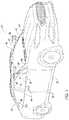
- FIG. 1is a perspective view of an example vehicle.
- FIG. 2is a top view of the vehicle.
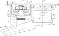
- FIG. 3is a perspective view of a sensor assembly of the vehicle.
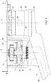
- FIG. 4is a cross-sectional view of the sensor assembly.
- FIG. 5Ais a cross-sectional view of a first example of a duct of the sensor assembly.
- FIG. 5Bis a cross-sectional view of a second example of the duct.
- An assemblyincludes a sensor arm extensible from a pillar of a vehicle, a sensor and a sensor window each attached to the sensor arm, a blower positioned between the sensor window and the pillar, and a duct extending from the blower to direct airflow from the blower across the sensor window.
- the sensor windowmay be cylindrical.
- the sensor windowmay define an axis, and the duct may direct the airflow parallel to the axis.
- the ductmay have an opening extending along an arc of a circle centered on the axis.
- the openingmay be positioned to create an air curtain across the sensor window when the blower is operating.
- the openingmay extend at least 180° about the axis.
- the openingmay have a width that is substantially constant along the arc of the circle.
- the openingmay extend parallel to the axis from an entrance end to an exit end, and the width of the opening may be narrower at the exit end than at the entrance end.
- the ductmay have a plurality of nozzles each positioned on a circle centered on the axis.
- the axismay be a first axis
- the blowermay include an impeller rotatable about a second axis parallel to the first axis.
- the ductmay define a passage through which the blower directs the airflow, and the passage may extend from above the blower to above the sensor window.
- the passagemay include a first circular passage disposed above the impeller and a second circular passage above the sensor window. A diameter of the first circular passage may be at least as great as a diameter of the impeller, and a diameter of the second circular passage may be at least as great as a diameter of the sensor window.
- the passagemay include a connecting passage extending from the first circular passage to the second circular passage. A width of the connecting passage may be narrower than the diameter of the first circular passage and narrower than the diameter of the second circular passage.
- the assemblymay include the pillar of the vehicle.
- the pillarmay extend from a first end at a bottom of a windshield to a second end at a top of the windshield, and the sensor arm may be attached to the pillar spaced from the first end and from the second end.
- the assemblymay include the windshield.
- the blowermay include an inlet, and the assembly may further include a channel extending through the sensor arm and connected to the inlet.
- the assemblymay include a filter positioned across the inlet.
- the cleaning system described hereincleans a vehicle sensor and may thus allow the sensor to more accurately detect the external environment.
- the sensoris positioned relative to the rest of the vehicle so as to not cause significant drag or increase a height of the vehicle by being located on a roof of the vehicle, while still maintaining a wide field of view for the sensor.
- the cleaning systemis positioned relative to the rest of the vehicle so that the cleaning system will not block the field of view of the sensor nor of a human driver of the vehicle who is looking through the windshield or a window of the vehicle.
- a body 32 of a vehicle 30may include A pillars 34 , B pillars 36 , C pillars 38 , and roof rails 40 .
- the A pillars 34may extend between a windshield 42 and windows 44 and from a first end 46 at a bottom of the windshield 42 to a second end 48 at a top of the windshield 42 .
- the adjectives “first” and “second”are used throughout this document as identifiers and are not intended to signify importance or order.
- the B pillars 36may extend between the windows 44 of adjacent doors 50 .
- the C pillars 38may extend between the windows 44 and a backlite 52 .
- the body 32may also include D pillars (not shown) if the vehicle 30 is, e.g., an SUV, crossover, minivan, or station wagon, in which case the C pillars 38 extend between the windows 44 of rear doors 50 and rear left and right windows 44 , and the D pillars extend between the rear right and left windows 44 and the backlite 52 .
- the roof rails 40extend along the windows 44 from the A pillar 34 to the B pillar 36 to the C pillar 38 .
- the windshield 42 , windows 44 , and backlite 52may be formed of any suitably durable transparent material, including glass such as laminated, tempered glass or plastic such as Plexiglas or polycarbonate.
- the windshield 42is located adjacent the A pillars 34 .
- the vehicle 30may include side-view mirrors 54 .
- the side-view mirrors 54may be located on the front doors 50 or on the body 32 near the bottom of the windshield 42 .
- the side-view mirrors 54may be visible to a human driver through the windows 44 and provide a reflected view of a vehicle-rearward direction to the driver.
- a sensor arm 56extends from one of the pillars 34 , 36 , 38 of the vehicle 30 , e.g., the A pillar 34 , to a sensor housing 58 .
- the sensor arm 56may be located between the ends 46 , 48 of the A pillar 34 , that is, spaced from the bottom of the windshield 42 and from the top of the windshield 42 , that is, spaced from the first end 46 and from the second end 48 .
- the sensor arm 56may be attached to a bottom surface 60 of the sensor housing 58 .
- the sensor arm 56may have a tubular or other hollow shape, that is, a cavity may extend through the sensor arm 56 . The cavity may allow wiring, tubes, etc. to pass through the sensor arm 56 while being shielded from the outside environment.
- the sensor housing 58is supported by the sensor arm 56 .
- the sensor housing 58may have a cylindrical shape with a top surface 62 , the bottom surface 60 , and a side surface 64 .
- the top surface 62faces up, that is, in a vehicle-upward direction
- the bottom surface 60faces down, that is, in a vehicle-downward direction.
- the side-view mirrors 54may be located below the sensor housings 58 , that is, in a vehicle-downward direction from the sensor housings 58 , and each bottom surface 60 may face each side-view mirror 54 .
- the cylindrical shape of the sensor housing 58defines the axis A, which runs through a center of the sensor housing 58 .
- the axis Ais oriented vertically relative to the vehicle 30 .
- a sensor 66is disposed inside the sensor housing 58 and is attached to and supported by the sensor arm 56 .
- the sensor 66may be designed to detect features of the outside world; for example, the sensor 66 may be a radar sensor, a scanning laser range finder, a light detection and ranging (LIDAR) device, or an image processing sensor such as a camera.
- the sensor 66may be a LIDAR device.
- a LIDAR devicedetects distances to objects by emitting laser pulses at a particular wavelength and measuring the time of flight for the pulse to travel to the object and back.
- the side surface 64may include a sensor window 68 .
- the sensor window 68is supported by and attached to the sensor arm 56 .
- the sensor window 68may be cylindrical and may also define the axis A.
- the sensor window 68extends about the axis A.
- the sensor window 68may extend fully about the axis A, that is, 360°, or partially about the axis A.
- the sensor window 68extends along the axis A from a bottom edge 70 to a top edge 72 .
- the bottom edge 70may be at the bottom surface 60 or may be spaced from the bottom surface 60 along the side surface 64 .
- the top edge 72may be at the top surface 62 or may be spaced from the top surface 62 along the side surface 64 .
- the sensor window 68has a diameter.
- the diameter of the sensor window 68may be the same as the rest of the side surface 64 , if any; in other words, the sensor window 68 may be flush or substantially flush with the side surface 64 .
- “Substantially flush”means a seam between the sensor window 68 and the rest of the side surface 64 does not cause turbulence in air flowing along the side surface 64 .
- At least some of the sensor window 68is transparent with respect to whatever medium the sensor 66 is capable of detecting. For example, if the sensor 66 is a LIDAR device, then the sensor window 68 is transparent with respect to visible light at the wavelength generated by the sensor 66 .
- the sensor window 68has an obstructed portion and a viewing portion.
- the obstructed portionfaces the vehicle 30 , and the viewing portion faces away from the vehicle 30 .
- the obstructed portionis the area of the sensor window 68 for which the sensor 66 is blocked by the vehicle 30 from detecting the external environment.
- the viewing portionis the area of the sensor window 68 through which the sensor 66 is able to detect the external environment without obstruction by the vehicle 30 . If the sensor arm 56 extends from between the ends 46 , 48 of the A pillar 34 , as shown in FIG. 1 , then the viewing portion may be approximately equal to or greater than 270°.
- a channel 74extends through the sensor arm 56 and is connected to an inlet 76 of a blower 78 .
- the channel 74is distinct from the cavity of the sensor arm 56 described above.
- the channel 74may be connected to a passenger cabin of the vehicle 30 ; in other words, air may flow from the passenger cabin to the channel 74 .
- the channel 74may provide a path for airflow from the passenger cabin to the inlet 76 .
- the blower 78is positioned between the sensor window 68 and the A pillar 34 . “Positioned between,” for the purposes of this disclosure, means that a straight line from the sensor window 68 to the A pillar 34 intersects the blower 78 . More specifically, the blower 78 may be laterally positioned between the sensor window 68 and the A pillar 34 , i.e., a horizontal straight line from the sensor window 68 to the A pillar 34 intersects the blower 78 .
- the blower 78may include the inlet 76 , an air filter 80 , a drive motor 82 , and an impeller 84 rotatably coupled to the drive motor 82 .
- the drive motor 82 and/or the impeller 84may be positioned between the sensor window 68 and the A pillar 34 .
- the blower 78may be a centrifugal fan (as shown in FIG. 4 ), an axial-flow fan, a cross-flow fan, or any other type of fan.
- the inlet 76leads from the channel 74 to the impeller 84 .
- the inlet 76may be a passageway, e.g., a tube.
- the inlet 76may face downward.
- the inlet 76may contain the air filter 80 .
- the air filter 80may be positioned across the inlet 76 , i.e., may cover a cross-section of the inlet 76 so that air cannot pass around the air filter 80 through the inlet 76 .
- the air filter 80may be formed of fibrous materials that remove solid particulates, e.g., dust, smog, pollen, etc., from the air.
- the impeller 84has vanes that, when the impeller 84 is rotated by the drive motor 82 , pull air from the inlet 76 and push air toward a duct 86 .
- the impeller 84may be rotatable about a second axis B.
- the second axis Bmay be parallel to the axis A.
- the drive motor 82may be coupled to the sensor arm 56 and to the impeller 84 .
- the drive motor 82may be fixed to the sensor arm 56 , for example, by fastening.
- the drive motor 82may be disposed above or below the impeller 84 .
- the drive motor 82may be, for example, an electric motor having a rotational output.
- the duct 86extends from the blower 78 to direct airflow from the blower 78 across the sensor window 68 .
- the duct 86defines a passage 88 through which the blower 78 directs the airflow.
- the passage 88extends from above the blower 78 to above the sensor window 68 .
- the impeller 84directs airflow upward to the duct 86
- the duct 86directs the airflow horizontally from above the blower 78 to above the sensor window 68 .
- the duct 86then directs the airflow downward across the sensor window 68 , i.e., parallel to the axis A.
- the passage 88may include a first circular passage 90 , a connecting passage 92 , and a second circular passage 94 .
- the first circular passage 90is disposed above the impeller 84 .
- a diameter of the first circular passage 90is at least as great as a diameter of the impeller 84 .
- the first circular passage 90may have a ring shape, as shown in FIGS. 5A-B , with the first circular passage 90 extending about a solid circle, or the first circular passage 90 may have a circular shape with no solid center.
- the connecting passage 92extends from the first circular passage 90 to the second circular passage 94 .
- a width of the connecting passage 92may be narrower than the diameter of the first circular passage 90 and narrower than a diameter of the second circular passage 94 .
- the second circular passage 94is disposed above the sensor window 68 .
- the diameter of the second circular passage 94is at least as great as the diameter of the sensor window 68 .
- the second circular passage 94may have a ring shape, as shown in FIGS. 5A-B , with the second circular passage 94 extending about a solid circle, or the second circular passage 94 may have a circular shape with no solid center.
- the duct 86includes at least one pathway for directing airflow downward across the sensor window 68 .
- the pathway(s)may create an air curtain across the sensor window 68 when the blower 78 is operating.
- the duct 86may have an opening 96 extending along an arc of a circle centered on the axis A.
- An “arc of a circle”should be understood according to its plain and ordinary meaning, i.e., a connected section of a circumference of a circle, i.e., a partial circle.
- the opening 96may extend fully about the axis A, i.e., 360°, or the opening 96 may extend partially about the axis A.
- the opening 96may extend at least 180° about the axis A.
- the opening 96has the width that may be substantially constant circumferentially, i.e., along the arc of the circle; thus, difference in air flow through the opening 96 at different points about the circle is negligible.
- the opening 96extends parallel to the axis from an entrance end at the second circular passage 94 to an exit end.
- the width of the opening 96may be narrower at the exit end than at the entrance end.
- the opening 96is positioned to create an air curtain across the sensor window 68 when the blower 78 is operating.
- An “air curtain”is a layer of moving air. In other words, the airflow from the opening 96 travels vertically across the sensor window 68 and substantially covers, that is, covers most of, the sensor window 68 or the viewing portion of the sensor window 68 . “Across” means from one side of something to the other side.
- the air curtainserves as a barrier and may deflect debris or other potential obstructions from contacting the sensor window 68 .
- the duct 86may have a plurality of nozzles 98 each positioned on a circle centered on the axis A.
- the nozzles 98may be spaced circumferentially about the sensor housing 58 .
- the nozzles 98may be spaced evenly about the axis A or partially about the axis A, or the nozzles 98 may be more closely spaced on a vehicle-forward (i.e., facing a front of the vehicle) side of the sensor housing 58 than on a vehicle-rearward (i.e., facing a rear of the vehicle) side of the sensor housing 58 .
- the nozzles 98may be positioned to create an air curtain across the sensor window 68 when the blower 78 is operating. In other words, the airflow from the nozzles 98 travels vertically across the sensor window 68 , that is, from the top edge 72 to the bottom edge 70 , and substantially covers the sensor window 68 or the viewing portion of the sensor window 68 .
- the drive motor 82drives the blower 78 .
- the impeller 84pulls air through the inlet 76 and the air filter 80 from the passenger cabin and pushes the air into the duct 86 .
- the airtravels through the passage 88 from the first circular passage 90 to the connecting passage 92 to the second circular passage 94 to the opening 96 .
- the opening 96directs the air across the sensor window 68 .
- the continuous airflowmay deflect dirt, particles, etc. from contacting the sensor window 68 , keeping the sensor window 68 clear and facilitating the operation of the sensor 66 .
Landscapes
- Engineering & Computer Science (AREA)
- Mechanical Engineering (AREA)
- Aviation & Aerospace Engineering (AREA)
- Radar, Positioning & Navigation (AREA)
- Remote Sensing (AREA)
- Physics & Mathematics (AREA)
- General Physics & Mathematics (AREA)
- Automation & Control Theory (AREA)
- Investigating Or Analysing Materials By Optical Means (AREA)
Abstract
Description
Claims (19)
Priority Applications (3)
| Application Number | Priority Date | Filing Date | Title |
|---|---|---|---|
| US15/641,406US10610074B2 (en) | 2017-07-05 | 2017-07-05 | Sensor cleaning apparatus |
| DE102018115896.3ADE102018115896A1 (en) | 2017-07-05 | 2018-06-30 | Sensor cleaning device |
| CN201810706287.8ACN109204238B (en) | 2017-07-05 | 2018-07-02 | Sensor cleaning device |
Applications Claiming Priority (1)
| Application Number | Priority Date | Filing Date | Title |
|---|---|---|---|
| US15/641,406US10610074B2 (en) | 2017-07-05 | 2017-07-05 | Sensor cleaning apparatus |
Publications (2)
| Publication Number | Publication Date |
|---|---|
| US20190008345A1 US20190008345A1 (en) | 2019-01-10 |
| US10610074B2true US10610074B2 (en) | 2020-04-07 |
Family
ID=64666303
Family Applications (1)
| Application Number | Title | Priority Date | Filing Date |
|---|---|---|---|
| US15/641,406Active2038-03-29US10610074B2 (en) | 2017-07-05 | 2017-07-05 | Sensor cleaning apparatus |
Country Status (3)
| Country | Link |
|---|---|
| US (1) | US10610074B2 (en) |
| CN (1) | CN109204238B (en) |
| DE (1) | DE102018115896A1 (en) |
Families Citing this family (16)
| Publication number | Priority date | Publication date | Assignee | Title |
|---|---|---|---|---|
| US9701307B1 (en) | 2016-04-11 | 2017-07-11 | David E. Newman | Systems and methods for hazard mitigation |
| US10816635B1 (en) | 2018-12-20 | 2020-10-27 | Autonomous Roadway Intelligence, Llc | Autonomous vehicle localization system |
| US10814474B2 (en) | 2018-12-20 | 2020-10-27 | Autonomous Roadway Intelligence, Llc | Identification and localization of mobile robots |
| US10820349B2 (en) | 2018-12-20 | 2020-10-27 | Autonomous Roadway Intelligence, Llc | Wireless message collision avoidance with high throughput |
| JP7470055B2 (en)* | 2019-02-01 | 2024-04-17 | 株式会社小糸製作所 | Vehicle cleaner |
| US10820182B1 (en) | 2019-06-13 | 2020-10-27 | David E. Newman | Wireless protocols for emergency message transmission |
| US10939471B2 (en) | 2019-06-13 | 2021-03-02 | David E. Newman | Managed transmission of wireless DAT messages |
| US10713950B1 (en) | 2019-06-13 | 2020-07-14 | Autonomous Roadway Intelligence, Llc | Rapid wireless communication for vehicle collision mitigation |
| US11598865B2 (en) | 2019-06-14 | 2023-03-07 | Ford Global Technologies, Llc | Sensor assembly with cleaning |
| US10802121B1 (en)* | 2019-10-09 | 2020-10-13 | Ford Global Technologies, Llc | Cleaning apparatus for sensor |
| DE102020207444B4 (en) | 2020-06-16 | 2023-10-05 | Volkswagen Aktiengesellschaft | Method for removing external contamination on a vehicle and vehicle with a device for removing such contamination |
| US12071107B2 (en) | 2020-07-28 | 2024-08-27 | Lg Innotek Co., Ltd. | Systems and methods for providing a flow of air about a lens of a sensor of a vehicle |
| CN112277817B (en)* | 2020-10-30 | 2022-03-01 | 丹阳市玺越汽车配件制造有限公司 | External metal luggage rack of car |
| US12115948B2 (en)* | 2021-10-20 | 2024-10-15 | Ford Global Technologies, Llc | Sensor assembly with cleaning |
| US11975599B2 (en)* | 2021-12-08 | 2024-05-07 | Ford Global Technologies, Llc | Sensor assembly with deflector |
| NO348028B1 (en)* | 2022-02-18 | 2024-06-24 | Roadguard As | Drive-over tire tread depth gauging system and method |
Citations (15)
| Publication number | Priority date | Publication date | Assignee | Title |
|---|---|---|---|---|
| WO2004010838A2 (en)* | 2002-07-26 | 2004-02-05 | Innodesk Business Tools, Inc. | Portable hand-held battery-operated dust blower |
| US6890080B2 (en)* | 2002-01-25 | 2005-05-10 | Ircon, Inc. | Air purge system for optical sensor |
| US20060068696A1 (en) | 2004-09-16 | 2006-03-30 | Ashford James A | Apparatus and method for laser scanner cleaning and protection |
| US7495747B2 (en) | 2005-01-11 | 2009-02-24 | Denso Corporation | Radar apparatus |
| US20120162428A1 (en) | 2010-12-27 | 2012-06-28 | Jay Young Wee | Housing for exterior imaging device of vehicle |
| EP2605043A1 (en) | 2011-12-15 | 2013-06-19 | Upwind | A self-cleaning light detection and ranging device |
| US20140117701A1 (en)* | 2012-10-31 | 2014-05-01 | Kenneth Davis | Compressed Air Vehicle Screen Clearing System |
| US8857775B1 (en)* | 2013-07-22 | 2014-10-14 | Gopro, Inc. | Camera mount with spring clamp |
| CN203920685U (en) | 2014-06-25 | 2014-11-05 | 华创车电技术中心股份有限公司 | Exterior Lens Cleaning System |
| US20160209645A1 (en) | 2013-11-27 | 2016-07-21 | Halliburton Energy Services, Inc. | Air Curtain Generator for Optical Sensing Devices |
| US20160244028A1 (en) | 2015-02-25 | 2016-08-25 | Toyota Jidosha Kabushiki Kaisha | Peripheral information detection device and self-driving vehicle |
| US20160311405A1 (en) | 2015-04-22 | 2016-10-27 | Ford Global Technologies, Llc | Vehicle camera cleaning system |
| US10073178B2 (en)* | 2015-03-24 | 2018-09-11 | Toyota Jidosha Kabushiki Kaisha | Placement structure for peripheral information detecting sensor, and self-driving vehicle |
| US10220817B2 (en)* | 2016-07-18 | 2019-03-05 | Uber Technologies, Inc. | Sensor cleaning system for vehicles |
| US10252703B2 (en)* | 2015-05-20 | 2019-04-09 | Denso Corporation | System for cleaning on-vehicle optical sensor and method for the same |
Family Cites Families (3)
| Publication number | Priority date | Publication date | Assignee | Title |
|---|---|---|---|---|
| FR2570658B1 (en)* | 1984-06-21 | 1988-11-25 | Juttet Bernard | NEW TYPE OF NET MIRROR IN ALL ATMOSPHERIC CIRCUMSTANCES |
| CN201265931Y (en)* | 2008-07-28 | 2009-07-01 | 刘飞 | Automobile air conditioner control device using clean energy |
| US20180265049A1 (en)* | 2017-03-14 | 2018-09-20 | Ford Global Technologies, Llc | Sensor and cleaning apparatus |
- 2017
- 2017-07-05USUS15/641,406patent/US10610074B2/enactiveActive
- 2018
- 2018-06-30DEDE102018115896.3Apatent/DE102018115896A1/enactivePending
- 2018-07-02CNCN201810706287.8Apatent/CN109204238B/enactiveActive
Patent Citations (15)
| Publication number | Priority date | Publication date | Assignee | Title |
|---|---|---|---|---|
| US6890080B2 (en)* | 2002-01-25 | 2005-05-10 | Ircon, Inc. | Air purge system for optical sensor |
| WO2004010838A2 (en)* | 2002-07-26 | 2004-02-05 | Innodesk Business Tools, Inc. | Portable hand-held battery-operated dust blower |
| US20060068696A1 (en) | 2004-09-16 | 2006-03-30 | Ashford James A | Apparatus and method for laser scanner cleaning and protection |
| US7495747B2 (en) | 2005-01-11 | 2009-02-24 | Denso Corporation | Radar apparatus |
| US20120162428A1 (en) | 2010-12-27 | 2012-06-28 | Jay Young Wee | Housing for exterior imaging device of vehicle |
| EP2605043A1 (en) | 2011-12-15 | 2013-06-19 | Upwind | A self-cleaning light detection and ranging device |
| US20140117701A1 (en)* | 2012-10-31 | 2014-05-01 | Kenneth Davis | Compressed Air Vehicle Screen Clearing System |
| US8857775B1 (en)* | 2013-07-22 | 2014-10-14 | Gopro, Inc. | Camera mount with spring clamp |
| US20160209645A1 (en) | 2013-11-27 | 2016-07-21 | Halliburton Energy Services, Inc. | Air Curtain Generator for Optical Sensing Devices |
| CN203920685U (en) | 2014-06-25 | 2014-11-05 | 华创车电技术中心股份有限公司 | Exterior Lens Cleaning System |
| US20160244028A1 (en) | 2015-02-25 | 2016-08-25 | Toyota Jidosha Kabushiki Kaisha | Peripheral information detection device and self-driving vehicle |
| US10073178B2 (en)* | 2015-03-24 | 2018-09-11 | Toyota Jidosha Kabushiki Kaisha | Placement structure for peripheral information detecting sensor, and self-driving vehicle |
| US20160311405A1 (en) | 2015-04-22 | 2016-10-27 | Ford Global Technologies, Llc | Vehicle camera cleaning system |
| US10252703B2 (en)* | 2015-05-20 | 2019-04-09 | Denso Corporation | System for cleaning on-vehicle optical sensor and method for the same |
| US10220817B2 (en)* | 2016-07-18 | 2019-03-05 | Uber Technologies, Inc. | Sensor cleaning system for vehicles |
Also Published As
| Publication number | Publication date |
|---|---|
| CN109204238A (en) | 2019-01-15 |
| US20190008345A1 (en) | 2019-01-10 |
| DE102018115896A1 (en) | 2019-01-10 |
| CN109204238B (en) | 2025-02-07 |
Similar Documents
| Publication | Publication Date | Title |
|---|---|---|
| US10610074B2 (en) | Sensor cleaning apparatus | |
| US20180265049A1 (en) | Sensor and cleaning apparatus | |
| CN109141494B (en) | Sensor equipment | |
| US10442402B2 (en) | Sensor and cleaning apparatus | |
| US10845465B2 (en) | Vehicle object-detection sensor assembly | |
| US11156485B1 (en) | Rotating sensor assembly | |
| CN109819627B (en) | Sensor assembly | |
| US20190278078A1 (en) | Vehicle object-detection sensor assembly | |
| US11579252B2 (en) | Sensor-cooling apparatus | |
| US11827189B2 (en) | Sensor assembly for a vehicle | |
| US11520012B2 (en) | Sensor drainage system | |
| US20210031732A1 (en) | Sensor assembly with cleaning | |
| US11408984B2 (en) | Sensor-drainage apparatus | |
| CN112285731A (en) | Vehicle sensor assembly | |
| CN118457443A (en) | Sensor assembly | |
| CN118310566A (en) | Sensor assembly | |
| CN119147025A (en) | Sensor assembly with baffle | |
| US20220041138A1 (en) | Sensor apparatus with cleaning | |
| US12351138B2 (en) | Sensor assembly with cleaning | |
| JP2003175767A (en) | Infrared camera and vehicle with infrared camera | |
| CN118220002A (en) | Sensor assembly | |
| US12181608B2 (en) | Rotating sensor assembly | |
| US11733356B2 (en) | Sensor apparatus with drainage | |
| US12155916B2 (en) | Vehicle sensor assembly | |
| US12351112B2 (en) | Liftgate mounted sensor assembly |
Legal Events
| Date | Code | Title | Description |
|---|---|---|---|
| AS | Assignment | Owner name:FORD GLOBAL TECHNOLOGIES, LLC, MICHIGAN Free format text:ASSIGNMENT OF ASSIGNORS INTEREST;ASSIGNORS:BLACK, SCOTT A.;SCHMIDT, DAVID;REEL/FRAME:042895/0985 Effective date:20170628 | |
| STPP | Information on status: patent application and granting procedure in general | Free format text:DOCKETED NEW CASE - READY FOR EXAMINATION | |
| STPP | Information on status: patent application and granting procedure in general | Free format text:NON FINAL ACTION MAILED | |
| STPP | Information on status: patent application and granting procedure in general | Free format text:RESPONSE TO NON-FINAL OFFICE ACTION ENTERED AND FORWARDED TO EXAMINER | |
| STPP | Information on status: patent application and granting procedure in general | Free format text:FINAL REJECTION MAILED | |
| STPP | Information on status: patent application and granting procedure in general | Free format text:RESPONSE AFTER FINAL ACTION FORWARDED TO EXAMINER | |
| STPP | Information on status: patent application and granting procedure in general | Free format text:NOTICE OF ALLOWANCE MAILED -- APPLICATION RECEIVED IN OFFICE OF PUBLICATIONS | |
| STPP | Information on status: patent application and granting procedure in general | Free format text:PUBLICATIONS -- ISSUE FEE PAYMENT RECEIVED | |
| STCF | Information on status: patent grant | Free format text:PATENTED CASE | |
| MAFP | Maintenance fee payment | Free format text:PAYMENT OF MAINTENANCE FEE, 4TH YEAR, LARGE ENTITY (ORIGINAL EVENT CODE: M1551); ENTITY STATUS OF PATENT OWNER: LARGE ENTITY Year of fee payment:4 |