US10608449B2 - Electrical charging devices with translating stabilizers - Google Patents
Electrical charging devices with translating stabilizersDownload PDFInfo
- Publication number
- US10608449B2 US10608449B2US15/818,711US201715818711AUS10608449B2US 10608449 B2US10608449 B2US 10608449B2US 201715818711 AUS201715818711 AUS 201715818711AUS 10608449 B2US10608449 B2US 10608449B2
- Authority
- US
- United States
- Prior art keywords
- housing
- linkage
- armatures
- electronic device
- electrical conductor
- Prior art date
- Legal status (The legal status is an assumption and is not a legal conclusion. Google has not performed a legal analysis and makes no representation as to the accuracy of the status listed.)
- Expired - Fee Related
Links
Images


Classifications
- H—ELECTRICITY
- H02—GENERATION; CONVERSION OR DISTRIBUTION OF ELECTRIC POWER
- H02J—CIRCUIT ARRANGEMENTS OR SYSTEMS FOR SUPPLYING OR DISTRIBUTING ELECTRIC POWER; SYSTEMS FOR STORING ELECTRIC ENERGY
- H02J7/00—Circuit arrangements for charging or depolarising batteries or for supplying loads from batteries
- H02J7/0042—Circuit arrangements for charging or depolarising batteries or for supplying loads from batteries characterised by the mechanical construction
- H02J7/0044—Circuit arrangements for charging or depolarising batteries or for supplying loads from batteries characterised by the mechanical construction specially adapted for holding portable devices containing batteries
- H—ELECTRICITY
- H01—ELECTRIC ELEMENTS
- H01R—ELECTRICALLY-CONDUCTIVE CONNECTIONS; STRUCTURAL ASSOCIATIONS OF A PLURALITY OF MUTUALLY-INSULATED ELECTRICAL CONNECTING ELEMENTS; COUPLING DEVICES; CURRENT COLLECTORS
- H01R13/00—Details of coupling devices of the kinds covered by groups H01R12/70 or H01R24/00 - H01R33/00
- H01R13/44—Means for preventing access to live contacts
- H—ELECTRICITY
- H01—ELECTRIC ELEMENTS
- H01R—ELECTRICALLY-CONDUCTIVE CONNECTIONS; STRUCTURAL ASSOCIATIONS OF A PLURALITY OF MUTUALLY-INSULATED ELECTRICAL CONNECTING ELEMENTS; COUPLING DEVICES; CURRENT COLLECTORS
- H01R13/00—Details of coupling devices of the kinds covered by groups H01R12/70 or H01R24/00 - H01R33/00
- H01R13/66—Structural association with built-in electrical component
- H—ELECTRICITY
- H01—ELECTRIC ELEMENTS
- H01R—ELECTRICALLY-CONDUCTIVE CONNECTIONS; STRUCTURAL ASSOCIATIONS OF A PLURALITY OF MUTUALLY-INSULATED ELECTRICAL CONNECTING ELEMENTS; COUPLING DEVICES; CURRENT COLLECTORS
- H01R31/00—Coupling parts supported only by co-operation with counterpart
- H01R31/06—Intermediate parts for linking two coupling parts, e.g. adapter
- H—ELECTRICITY
- H01—ELECTRIC ELEMENTS
- H01R—ELECTRICALLY-CONDUCTIVE CONNECTIONS; STRUCTURAL ASSOCIATIONS OF A PLURALITY OF MUTUALLY-INSULATED ELECTRICAL CONNECTING ELEMENTS; COUPLING DEVICES; CURRENT COLLECTORS
- H01R33/00—Coupling devices specially adapted for supporting apparatus and having one part acting as a holder providing support and electrical connection via a counterpart which is structurally associated with the apparatus, e.g. lamp holders; Separate parts thereof
- H01R33/05—Two-pole devices
- H02J7/0052—
- H—ELECTRICITY
- H04—ELECTRIC COMMUNICATION TECHNIQUE
- H04M—TELEPHONIC COMMUNICATION
- H04M1/00—Substation equipment, e.g. for use by subscribers
- H04M1/72—Mobile telephones; Cordless telephones, i.e. devices for establishing wireless links to base stations without route selection
- H04M1/724—User interfaces specially adapted for cordless or mobile telephones
- H04M1/72403—User interfaces specially adapted for cordless or mobile telephones with means for local support of applications that increase the functionality
- H04M1/72409—User interfaces specially adapted for cordless or mobile telephones with means for local support of applications that increase the functionality by interfacing with external accessories
- H—ELECTRICITY
- H01—ELECTRIC ELEMENTS
- H01R—ELECTRICALLY-CONDUCTIVE CONNECTIONS; STRUCTURAL ASSOCIATIONS OF A PLURALITY OF MUTUALLY-INSULATED ELECTRICAL CONNECTING ELEMENTS; COUPLING DEVICES; CURRENT COLLECTORS
- H01R13/00—Details of coupling devices of the kinds covered by groups H01R12/70 or H01R24/00 - H01R33/00
- H01R13/60—Means for supporting coupling part when not engaged
- H—ELECTRICITY
- H01—ELECTRIC ELEMENTS
- H01R—ELECTRICALLY-CONDUCTIVE CONNECTIONS; STRUCTURAL ASSOCIATIONS OF A PLURALITY OF MUTUALLY-INSULATED ELECTRICAL CONNECTING ELEMENTS; COUPLING DEVICES; CURRENT COLLECTORS
- H01R24/00—Two-part coupling devices, or either of their cooperating parts, characterised by their overall structure
- H01R24/66—Two-part coupling devices, or either of their cooperating parts, characterised by their overall structure with pins, blades or analogous contacts and secured to apparatus or structure, e.g. to a wall
- H01R24/68—Two-part coupling devices, or either of their cooperating parts, characterised by their overall structure with pins, blades or analogous contacts and secured to apparatus or structure, e.g. to a wall mounted on directly pluggable apparatus
- H—ELECTRICITY
- H01—ELECTRIC ELEMENTS
- H01R—ELECTRICALLY-CONDUCTIVE CONNECTIONS; STRUCTURAL ASSOCIATIONS OF A PLURALITY OF MUTUALLY-INSULATED ELECTRICAL CONNECTING ELEMENTS; COUPLING DEVICES; CURRENT COLLECTORS
- H01R31/00—Coupling parts supported only by co-operation with counterpart
- H01R31/06—Intermediate parts for linking two coupling parts, e.g. adapter
- H01R31/065—Intermediate parts for linking two coupling parts, e.g. adapter with built-in electric apparatus
- H02J2007/0062—
- H—ELECTRICITY
- H02—GENERATION; CONVERSION OR DISTRIBUTION OF ELECTRIC POWER
- H02J—CIRCUIT ARRANGEMENTS OR SYSTEMS FOR SUPPLYING OR DISTRIBUTING ELECTRIC POWER; SYSTEMS FOR STORING ELECTRIC ENERGY
- H02J50/00—Circuit arrangements or systems for wireless supply or distribution of electric power
- H02J50/10—Circuit arrangements or systems for wireless supply or distribution of electric power using inductive coupling
- H—ELECTRICITY
- H02—GENERATION; CONVERSION OR DISTRIBUTION OF ELECTRIC POWER
- H02J—CIRCUIT ARRANGEMENTS OR SYSTEMS FOR SUPPLYING OR DISTRIBUTING ELECTRIC POWER; SYSTEMS FOR STORING ELECTRIC ENERGY
- H02J7/00—Circuit arrangements for charging or depolarising batteries or for supplying loads from batteries
- H02J7/0068—Battery or charger load switching, e.g. concurrent charging and load supply
- H—ELECTRICITY
- H02—GENERATION; CONVERSION OR DISTRIBUTION OF ELECTRIC POWER
- H02J—CIRCUIT ARRANGEMENTS OR SYSTEMS FOR SUPPLYING OR DISTRIBUTING ELECTRIC POWER; SYSTEMS FOR STORING ELECTRIC ENERGY
- H02J7/00—Circuit arrangements for charging or depolarising batteries or for supplying loads from batteries
- H02J7/02—Circuit arrangements for charging or depolarising batteries or for supplying loads from batteries for charging batteries from AC mains by converters
- H—ELECTRICITY
- H04—ELECTRIC COMMUNICATION TECHNIQUE
- H04M—TELEPHONIC COMMUNICATION
- H04M1/00—Substation equipment, e.g. for use by subscribers
- H04M1/02—Constructional features of telephone sets
- H04M1/04—Supports for telephone transmitters or receivers
Definitions
- the present technologypertains to devices for electronic charging, and more specifically, but not by way of limitation, to electronic charging devices that couple with a wall outlet, as well as receive and retain an electronic device such as a Smartphone, tablet, laptop, and so forth, during charging.
- the devicesinclude stabilizers that are partially stored within tubular guides. These stabilizers can be deployed from within the tubular guides as desired to support the device when plugged into a power source.
- a cradleconfigured to receive and retain an electronic device
- an electronics sub-assemblycomprising: (i) a housing, wherein the housing comprises laterally positioned tubular guides; (ii) an electrical conductor that protrudes forwardly from the housing; and (iii) a circuit within the housing that processes an electrical charge received through the electrical conductor; (c) means for electrically coupling the electronics sub-assembly with the electronic device; and (d) a stabilizer comprising armatures, the armatures being slidingly received within the tubular guides of the housing for storage, further wherein the armatures extend from the tubular guides and pivot downwardly.
- an apparatusincluding: (a) an electronics sub-assembly comprising: (i) a housing, wherein the housing comprises laterally positioned tubular guides positioned inside of a sidewall that forms four sides of the housing; (ii) an electrical conductor; and (iii) a circuit within the housing that processes an electrical charge received through the electrical conductor; (b) means for electrically coupling the electronics sub-assembly with the electronic device; and (c) a stabilizer comprising armatures linked by a cross member, wherein the armatures are slidingly received within the tubular guides of the housing for storage, further wherein the armatures extend from the tubular guides to allow the cross member to contact a supporting surface when the electrical conductor is engaged with a power source providing the electrical charge.
- an apparatusincluding: (a) an electronics sub-assembly comprising: (i) a housing, wherein the housing comprises laterally positioned tubular guides positioned inside of a sidewall that forms four sides of the housing; (ii) an electrical conductor; and (iii) a circuit within the housing that processes an electrical charge received through the electrical conductor to allow for charging any of an electronic device and an electrical energy storage unit, the electrical energy storage unit disposed within the housing; (b) means for electrically coupling the electronics sub-assembly with the electronic device; and (c) a stabilizer comprising armatures linked by a cross member, wherein the armatures are slidingly received within the tubular guides of the housing for storage, further wherein the armatures extend from the tubular guides to allow the cross member to contact a supporting surface when the electrical conductor is engaged with the power source providing the electrical charge.
- the electrical energy storage unitis charged when the apparatus is coupled with a power source.
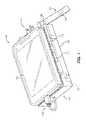
- FIG. 1is a perspective view of an example device constructed in accordance with the present disclosure.
- FIG. 2is a side view of the example device of FIG. 1 having a stabilizer in a stored configuration.
- FIG. 3is a side view of the example device of FIG. 1 having a stabilizer in a deployed configuration.
- FIG. 4is a front elevation view of the example device of FIG. 1 .
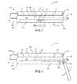
- FIG. 5is a top plan view of an example stabilizer constructed in accordance with the present disclosure.
- any and/or all methods and/or processes, at least as disclosed herein,can be at least partially performed via at least one entity, at least as described herein, in any manner, irrespective of the at least one entity have any relationship to the subject matter of the present disclosure.
- the present disclosureis directed to devices and apparatuses that charge electronic device, such as cell phones, laptops, Smartphones, and other similar devices.
- the devices disclosed hereincan be plugged into a power source, such as a wall outlet using an integrated electrical conductor.
- the devicesprovide a surface or cradle that holds an attached electronic device.
- the electronic deviceis coupled to a circuit in an example device through a cable or inductive charger interface.
- the circuitprocesses the electrical charge received from the power source to convert the same into an electrical charge that can be used to charge/power the electronic device.
- an example devicecan integrate a battery or other power storage that is charged when the device is plugged into the power source. This power storage can operate as a secondary or backup battery for the electronic device if necessary.
- FIG. 1is an example apparatus 100 of the present disclosure, comprising generally a cradle 102 and an electronics sub-assembly 104 that supports an electronic device 106 .
- the apparatus 100can be coupled to a power source, such as a wall outlet.
- the apparatus 100can be supported through use of a stabilizer 110 when the apparatus 100 is coupled with the power source.
- the cradle 102can comprise any suitable means for releaseably retaining the electronic device 106 .
- the cradle 102comprises a set of corner tabs, such as tab 112 . These tabs can be mounted to an upper surface of a housing of the electronics sub-assembly 104 , as will be discussed in greater detail below. These tabs are resilient and allow for the electronic device 106 to be held securely when placed in the cradle 102 , but the tabs flex to allow for the electronic device 106 to be removed as desired.
- the electronics sub-assemblycomprises a housing 114 .
- the housing 114provides an enclosure for a circuit that is used to process or otherwise condition an electrical charge received from a power source.
- the housing 114comprises an upper surface 116 from which the tabs, such as tab 112 extend.
- the upper surface 116 of the housingcan comprise a gripping layer or coating that helps secure the electronic device 106 in place in embodiments where a cradle and/or tabs are not desired.
- the electronics sub-assembly 104can comprise a circuit 118 in the form of a printed circuit board with various permutations of electrical components.
- the electronics sub-assembly 104is configured to transform the AC power waveform received from an outlet into DC power that is appropriate for charging the electronic device 106 .
- the electronics sub-assembly 104can include combinations of electrolytic capacitors, MOSFET switching transistors, flyback transformers, a controller integrated circuit, capacitors, diodes, R-C snubber circuits, EMI (electromagnetic interference) circuits, inductors, control chips, Schottky diodes, Tantalum filter capacitors, as well as any combinations thereof, in order to provide the desired transformation of AC to DC functions.
- electrolytic capacitorsMOSFET switching transistors, flyback transformers, a controller integrated circuit, capacitors, diodes, R-C snubber circuits, EMI (electromagnetic interference) circuits, inductors, control chips, Schottky diodes, Tantalum filter capacitors, as well as any combinations thereof, in order to provide the desired transformation of AC to DC functions.
- the electronics sub-assembly 104is an advanced flyback switching power supply that receives the AC voltage in ranges of 100 to 240 volts, and produces approximately five watts of smooth voltage power.
- AC line poweris converted to high voltage DC current using a diode bridge.
- the DC poweris switched off and on by a transistor controlled by a power supply controller IC.
- the chopped DC power supplyis fed back into a flyback transformer, which converts the DC power to a low voltage AC waveform.
- the AC waveformis then converted into DC, which is filtered with a filter to obtain smooth power that is substantially free of interference.
- the electronics assembly 106can comprise a feedback circuit that measures the voltage output to the electrical connector (e.g., prongs or USB, for example) and sends a signal to the controller IC, which adjusts the switching frequency to obtain a desired voltage.
- the electronics sub-assembly 104can comprise a circuit that is configured to convert AC to DC power.
- the circuitis configured to transform or step down a DC input at a first power level to a second power level that is usable for the electronic device 106 .
- the housing 114comprises a rechargeable battery 111 or other power storage means that receives and stores power when the apparatus 100 is coupled to the power source.
- the rechargeable battery 111discharges electricity to the electronic device 106 when the apparatus 100 is disconnected from the power source. In this way, the rechargeable battery 111 functions as a backup or secondary battery that can be used to extend the battery capacity of the electronic device 106 .
- the housing 114comprises an outer peripheral sidewall 120 that forms four sides of the housing 114 .
- the housing 114also comprises two laterally positioned tubular guides 122 and 124 . These laterally positioned tubular guides 122 and 124 receive armatures of the stabilizer 110 , as will be discussed in greater detail infra.
- the tubular guides 122 and 124are located internally to the outer peripheral sidewall 120 of the housing 114 .
- the housing 114comprises an electrical conductor 126 that protrudes forwardly from the housing 114 .
- the housing 114can have an opening underneath allowing for a finger to forwardly push the electrical conductor 126 to protrude from the housing 114 .
- the housing 114can have any of springs, magnets, protrusions with associated depressions, or raised edges with associated depressions.
- the electrical conductor 126is electrically coupled to the circuit 118 .
- the electrical conductor 126comprises any of prongs, USB interfaces, micro SD interfaces, lightning interfaces, and combinations thereof.
- the apparatus 100comprises a means for electrically coupling the electronics sub-assembly 104 with the electronic device 106 , such as a cable 128 .
- the means for electrically coupling the electronics sub-assembly 104 with the electronic device 106could include an inductive charging interface that is positioned on the upper surface 116 of the housing 114 . Assuming the electronic device 106 is capable of inductive charging, when the electronic device 106 is positioned in the cradle 102 , the inductive charging interface of the apparatus 100 mates with inductive charging interface of the electronic device 106 , allowing for inductive charging therebetween.
- the stabilizer 110comprises armatures 130 and 132 . These armatures 130 and 132 are slidingly received within the tubular guides 122 and 124 of the housing 114 for storage. The armatures 130 and 132 each extend from the tubular guides 122 and 124 , respectively. In some embodiments, the armatures 130 and 132 are each configured with pivoting linkages that allow for a portion of the stabilizer 110 to pivot.
- each of the armatures 130 and 132comprise a pair of linkages.
- armature 130comprises a first linkage 134 and a second linkage 136 .
- the second linkage 136pivots relative to the first linkage 134 .
- each of the terminal ends of the armatures 130 and 132contacts a supporting surface when the stabilizer 110 is in a deployed configuration.
- second linkage 136comprises a pin 138 that fits within an aperture 140 of the first linkage 134 .
- the first linkage 134comprises a stop 142 that limits the pivoting movement of the second linkage 136 relative to the first linkage 134 .
- the stop barcan connect armatures 130 and 132 (shown in FIGS. 4 and 5 ). The stop bar can limit the pivoting movement of the linkages, similar to how stop 142 functions.
- FIGS. 2 and 3illustrate the sliding and pivoting movement of armature 130 in FIGS. 2 and 3 .
- FIG. 2illustrates the stabilizer 110 in a stored configuration. When stored, the first linkage 134 and second linkage 136 are located within tubular guide 122 . The same positioning of armature 132 exists, although it is not illustrated in these views.
- the first linkage 134slides along a surface 152 (see FIG. 4 ) of the tubular guide 122 .
- This sliding engagementcan be facilitated by the sizing of the first linkage 134 relative to the tubular guide 122 or through a sliding interface between the surface 152 and the first linkage 134 such as a track 154 or other means.
- FIG. 3illustrates the stabilizer 110 in a deployed configuration.
- the armature 130is slid forward by an end user.
- the first linkage 134slightly protrudes from the tubular guide 122 and the second linkage 136 pivots downwardly until engaging with the stop 142 of the first linkage 134 .
- the end usercan slide the armatures back into their respective tubular guide to place the stabilizer back in the stored position.
- the armatures 130 and 132can be coupled using a cross member 150 .
- the cross member 150contacts a supporting surface when the stabilizer 110 is in a deployed configuration.
- the cross member 150is positioned outside the housing 114 directly below the electrical conductor 126 when the stabilizer 110 is in the stored configuration.
- the cross member 150provides the end user with a place to grip the stabilizer 110 in order to translate the stabilizer 110 from the stored to deployed configuration.
- a hyphenated term(e.g., “on-demand”) may be occasionally interchangeably used with its non-hyphenated version (e.g., “on demand”)
- a capitalized entrye.g., “Software”
- a non-capitalized versione.g., “software”
- a plural termmay be indicated with or without an apostrophe (e.g., PE's or PEs)
- an italicized terme.g., “N+1” may be interchangeably used with its non-italicized version (e.g., “N+1”).
- Such occasional interchangeable usesshall not be considered inconsistent with each other.
- a “means for”may be expressed herein in terms of a structure, such as a processor, a memory, an I/O device such as a camera, or combinations thereof.
- the “means for”may include an algorithm that is descriptive of a function or method step, while in yet other embodiments the “means for” is expressed in terms of a mathematical formula, prose, or as a flow chart or signal diagram.
- first, second, etc.may be used herein to describe various elements, components, regions, layers and/or sections, these elements, components, regions, layers and/or sections should not necessarily be limited by such terms. These terms are only used to distinguish one element, component, region, layer or section from another element, component, region, layer or section. Thus, a first element, component, region, layer or section discussed below could be termed a second element, component, region, layer or section without departing from the teachings of the present disclosure.
- Example embodiments of the present disclosureare described herein with reference to illustrations of idealized embodiments (and intermediate structures) of the present disclosure. As such, variations from the shapes of the illustrations as a result, for example, of manufacturing techniques and/or tolerances, are to be expected. Thus, the example embodiments of the present disclosure should not be construed as necessarily limited to the particular shapes of regions illustrated herein, but are to include deviations in shapes that result, for example, from manufacturing.
- Any and/or all elements, as disclosed herein,can be formed from a same, structurally continuous piece, such as being unitary, and/or be separately manufactured and/or connected, such as being an assembly and/or modules. Any and/or all elements, as disclosed herein, can be manufactured via any manufacturing processes, whether additive manufacturing, subtractive manufacturing and/or other any other types of manufacturing. For example, some manufacturing processes include three dimensional (3D) printing, laser cutting, computer numerical control (CNC) routing, milling, pressing, stamping, vacuum forming, hydroforming, injection molding, lithography and/or others.
- 3Dthree dimensional
- CNCcomputer numerical control
- any and/or all elements, as disclosed herein,can include, whether partially and/ or fully, a solid, including a metal, a mineral, a ceramic, an amorphous solid, such as glass, a glass ceramic, an organic solid, such as wood and/or a polymer, such as rubber, a composite material, a semiconductor, a nano-material, a biomaterial and/or any combinations thereof.
- a solidincluding a metal, a mineral, a ceramic, an amorphous solid, such as glass, a glass ceramic, an organic solid, such as wood and/or a polymer, such as rubber, a composite material, a semiconductor, a nano-material, a biomaterial and/or any combinations thereof.
- any and/or all elements, as disclosed herein,can include, whether partially and/or fully, a coating, including an informational coating, such as ink, an adhesive coating, a melt-adhesive coating, such as vacuum seal and/or heat seal, a release coating, such as tape liner, a low surface energy coating, an optical coating, such as for tint, color, hue, saturation, tone, shade, transparency, translucency, non-transparency, luminescence, anti-reflection and/or holographic, a photo-sensitive coating, an electronic and/or thermal property coating, such as for passivity, insulation, resistance or conduction, a magnetic coating, a water-resistant and/or waterproof coating, a scent coating and/or any combinations thereof.
- a coatingincluding an informational coating, such as ink, an adhesive coating, a melt-adhesive coating, such as vacuum seal and/or heat seal, a release coating, such as tape liner, a low surface energy coating, an optical coating, such as for tint, color, hue
- relative termssuch as “below,” “lower,” “above,” and “upper” may be used herein to describe one element's relationship to another element as illustrated in the accompanying drawings. Such relative terms are intended to encompass different orientations of illustrated technologies in addition to the orientation depicted in the accompanying drawings. For example, if a device in the accompanying drawings is turned over, then the elements described as being on the “lower” side of other elements would then be oriented on “upper” sides of the other elements. Similarly, if the device in one of the figures is turned over, elements described as “below” or “beneath” other elements would then be oriented “above” the other elements. Therefore, the example terms “below” and “lower” can, therefore, encompass both an orientation of above and below.
Landscapes
- Engineering & Computer Science (AREA)
- Power Engineering (AREA)
- Human Computer Interaction (AREA)
- Computer Networks & Wireless Communication (AREA)
- Signal Processing (AREA)
- Charge And Discharge Circuits For Batteries Or The Like (AREA)
Abstract
Description
Claims (20)
Priority Applications (1)
| Application Number | Priority Date | Filing Date | Title |
|---|---|---|---|
| US15/818,711US10608449B2 (en) | 2017-02-27 | 2017-11-20 | Electrical charging devices with translating stabilizers |
Applications Claiming Priority (12)
| Application Number | Priority Date | Filing Date | Title |
|---|---|---|---|
| US201762464077P | 2017-02-27 | 2017-02-27 | |
| US201762464517P | 2017-02-28 | 2017-02-28 | |
| US201762465705P | 2017-03-01 | 2017-03-01 | |
| US201762465871P | 2017-03-02 | 2017-03-02 | |
| US201762466576P | 2017-03-03 | 2017-03-03 | |
| US201762467230P | 2017-03-05 | 2017-03-05 | |
| US201762473225P | 2017-03-17 | 2017-03-17 | |
| US201762532060P | 2017-07-13 | 2017-07-13 | |
| US201762532843P | 2017-07-14 | 2017-07-14 | |
| US15/697,307US9997882B1 (en) | 2017-02-27 | 2017-09-06 | Electrical charging devices and assemblies |
| US15/788,708US10177584B2 (en) | 2017-02-27 | 2017-10-19 | Electrical charging devices and assemblies |
| US15/818,711US10608449B2 (en) | 2017-02-27 | 2017-11-20 | Electrical charging devices with translating stabilizers |
Related Parent Applications (1)
| Application Number | Title | Priority Date | Filing Date |
|---|---|---|---|
| US15/788,708Continuation-In-PartUS10177584B2 (en) | 2017-02-27 | 2017-10-19 | Electrical charging devices and assemblies |
Publications (2)
| Publication Number | Publication Date |
|---|---|
| US20180248392A1 US20180248392A1 (en) | 2018-08-30 |
| US10608449B2true US10608449B2 (en) | 2020-03-31 |
Family
ID=63247011
Family Applications (1)
| Application Number | Title | Priority Date | Filing Date |
|---|---|---|---|
| US15/818,711Expired - Fee RelatedUS10608449B2 (en) | 2017-02-27 | 2017-11-20 | Electrical charging devices with translating stabilizers |
Country Status (1)
| Country | Link |
|---|---|
| US (1) | US10608449B2 (en) |
Families Citing this family (5)
| Publication number | Priority date | Publication date | Assignee | Title |
|---|---|---|---|---|
| US10153649B2 (en) | 2014-06-29 | 2018-12-11 | William J. Warren | Computing device charging cases and methods of use |
| US10177584B2 (en) | 2017-02-27 | 2019-01-08 | William J. Warren | Electrical charging devices and assemblies |
| US10608449B2 (en)* | 2017-02-27 | 2020-03-31 | William J. Warren | Electrical charging devices with translating stabilizers |
| USD839187S1 (en) | 2017-04-22 | 2019-01-29 | William J. Warren | Charger with stabilizer |
| CN110011148B (en)* | 2019-04-24 | 2021-04-20 | 深圳市海盈智联实业有限公司 | Data transmission line switching interface |
Citations (123)
| Publication number | Priority date | Publication date | Assignee | Title |
|---|---|---|---|---|
| US2392445A (en) | 1944-06-26 | 1946-01-08 | Anderson Church | Combined wall switch and electric clock |
| US4536694A (en) | 1984-02-21 | 1985-08-20 | Solid State Chargers Research And Development | Battery-operated device with wall-mounted support |
| US5187744A (en) | 1992-01-10 | 1993-02-16 | Richter Gary L | Hand-held portable telephone holder |
| USD343107S (en) | 1992-03-23 | 1994-01-11 | Transfer Flow International, Inc. | Cabinet pull |
| US5305381A (en) | 1992-11-09 | 1994-04-19 | Wang Chin Y | Cradle for telephone |
| US5587645A (en) | 1994-03-09 | 1996-12-24 | Sony Corporation | Battery charger with night light for a cordless telephone |
| US5648712A (en) | 1995-08-29 | 1997-07-15 | Asian Micro Sources, Inc. | Universally interchangeable and modular power supply with integrated battery charger |
| US5679017A (en) | 1995-06-07 | 1997-10-21 | Duracell Inc. | Universal battery charger |
| US5762512A (en) | 1995-10-12 | 1998-06-09 | Symbol Technologies, Inc. | Latchable battery pack for battery-operated electronic device having controlled power shutdown and turn on |
| US5903645A (en) | 1996-10-23 | 1999-05-11 | Tsay; Wen-Feng | Clamping device for mobile phones |
| US6029215A (en) | 1994-11-08 | 2000-02-22 | Texas Instruments Incorporated | Computer ducking station with internal microprocessor |
| US6091611A (en) | 1994-04-26 | 2000-07-18 | Comarco Wireless Technologies, Inc. | Connectors adapted for controlling a small form factor power supply |
| US6341218B1 (en) | 1999-12-06 | 2002-01-22 | Cellport Systems, Inc. | Supporting and connecting a portable phone |
| US20020149695A1 (en) | 2001-04-12 | 2002-10-17 | Yasunobu Kayanuma | Cradle for information apparatus, cradle for digital camera and camera system |
| US6510067B1 (en) | 2000-11-03 | 2003-01-21 | Cisco Technology, Inc. | System, method and apparatus for protecting consumer electronic devices from brownouts and short duration power outages |
| US6518724B2 (en) | 2000-08-02 | 2003-02-11 | Simple Devices | Wall switch device and power outlet device |
| US20030218445A1 (en) | 2002-05-21 | 2003-11-27 | Behar Brad M. | Portable electronic device carrier and charger |
| US20040105024A1 (en) | 2002-11-26 | 2004-06-03 | Fuji Photo Film Co., Ltd. | Digital camera system |
| US6831848B2 (en) | 1994-04-26 | 2004-12-14 | Comarco Wireless Technologies, Inc. | Programmable power supply to simultaneously power a plurality of electronic devices |
| US20040251873A1 (en) | 2003-03-24 | 2004-12-16 | Simoes Felipe O. | Battery charging assembly |
| US6848802B2 (en) | 2002-09-18 | 2005-02-01 | Chung-Yang M. Chen | Computer light with extensible electric conductive wire |
| US6861822B2 (en) | 2003-04-03 | 2005-03-01 | Jose Wei | Battery charger having attached base |
| US20050178633A1 (en) | 2004-02-18 | 2005-08-18 | Sheng Hsin Liao | Computer peripheral with cable reeling device |
| US6938867B2 (en) | 2002-10-15 | 2005-09-06 | Wahl Clipper Corporation | Holder for a powered device |
| US20060105819A1 (en) | 2004-11-12 | 2006-05-18 | Bryant Liao | Portable electronic device's docking cradle on vechicle |
| US7066767B2 (en) | 2004-10-01 | 2006-06-27 | Sheng-Hsin Liao | Rotatable adapter device with multiple connectors |
| US7075779B2 (en) | 2003-04-09 | 2006-07-11 | Friwo Mobile Power Gmbh | Voltage transformer with hinged housing |
| US20060194467A1 (en) | 2005-01-10 | 2006-08-31 | Nigel Beasley | Flexible power adaptor system and method |
| US7166987B2 (en) | 2003-10-10 | 2007-01-23 | R. F. Tech Co., Ltd | Portable charger for mobile phone |
| US20070034753A1 (en) | 2002-01-31 | 2007-02-15 | Lee Brian A | Vehicle desk platform |
| US7254424B1 (en) | 2003-04-15 | 2007-08-07 | Reichert William E | Mobile telephone station |
| US20070258204A1 (en) | 2006-05-05 | 2007-11-08 | Asustek Computer Inc. | Reel device and the electronic product using the same |
| US20080157715A1 (en) | 2006-01-07 | 2008-07-03 | Egate-International Gmbh | Plug-type charger for small electrical device |
| USD573866S1 (en) | 2005-09-08 | 2008-07-29 | Smith John I | Tool grip |
| US20080227380A1 (en) | 2007-03-12 | 2008-09-18 | Hon Hai Precision Ind. Co., Ltd. | Portable storage device box |
| US20090047827A1 (en) | 2007-08-17 | 2009-02-19 | Sheng-Hsin Liao | Socket assembly |
| US7524197B2 (en) | 2007-04-30 | 2009-04-28 | Brookstone Purchasing, Inc. | Docking station for portable media player or storage device |
| US7528323B2 (en) | 2006-04-03 | 2009-05-05 | Hsinhan Wu | Power supply cover box |
| US7540748B2 (en) | 2007-04-11 | 2009-06-02 | Hewlett-Packard Development Company, L.P. | Flexible I/O connection system and method |
| US7551458B2 (en) | 2005-05-24 | 2009-06-23 | Carnevali Jeffrey D | Secure universal mounting apparatus |
| US7623182B2 (en) | 2006-04-10 | 2009-11-24 | Hewlett-Packard Development Company, L.P. | Camera interface module |
| US7682185B2 (en) | 2007-07-13 | 2010-03-23 | Sheng-Hsin Liao | Supporting device of a socket |
| US7699664B2 (en) | 2007-02-07 | 2010-04-20 | Yungs Group, Inc. | Multipurpose accessory for portable multimedia device |
| USD617863S1 (en) | 2003-12-02 | 2010-06-15 | Grip Pod Systems, Llc | Vertical fore grip top, handle and bipod |
| EP2228263A1 (en) | 2009-03-12 | 2010-09-15 | Pro-One S.R.L. | Recharging support for electronic devices |
| US7850484B2 (en) | 2008-08-28 | 2010-12-14 | Yamaha Corporation | Connecting apparatus for connecting to an electronic apparatus |
| US7857659B2 (en) | 2008-08-05 | 2010-12-28 | Asustek Computer Inc. | Electronic device with stretchable USB receptacle |
| US20110031287A1 (en) | 2008-09-09 | 2011-02-10 | Zero Chroma, LLC | Holder for Electronic Device with Support |
| US7887341B2 (en) | 2008-09-19 | 2011-02-15 | Sheng-Hsin Liao | Socket assembly |
| US8113873B1 (en) | 2009-09-22 | 2012-02-14 | Western Digital Technologies, Inc. | Pivot assisted storage device unloading mechanism |
| US20120049800A1 (en) | 2010-08-25 | 2012-03-01 | Clevx, Llc | Power supply system with automatic sensing mechanism and method of operation thereof |
| US20120077361A1 (en) | 2009-07-10 | 2012-03-29 | Research In Motion Limited | Electrical charger locking assembly |
| US20120178506A1 (en)* | 2011-01-12 | 2012-07-12 | Yeoshua Sorias | Detachably integrated battery charger for mobile cell phones and like devices |
| US8224408B2 (en) | 2005-01-24 | 2012-07-17 | Ralf Tomasini | Cradle for mobile phones |
| US8367235B2 (en) | 2008-01-18 | 2013-02-05 | Mophie, Inc. | Battery pack, holster, and extendible processing and interface platform for mobile devices |
| USD676380S1 (en) | 2012-06-20 | 2013-02-19 | Shenzhen Win-Top Electronic Tech Co., Ltd. | Portable charger with lights |
| US20130057215A1 (en) | 2011-09-07 | 2013-03-07 | Lakshman Rajeswaran | Attachable charger |
| US8415920B2 (en) | 2009-06-16 | 2013-04-09 | Sheng-Hsin Liao | Charger and a combination structure |
| US8414318B1 (en) | 2011-09-22 | 2013-04-09 | Leader Electronics Inc. | Power adapter having a plug module mounted on a substrate with multiple fasteners with clasps |
| US20130093220A1 (en) | 2011-10-13 | 2013-04-18 | Nick Pajic | Tray table with rotatable inner tray for electronic device docking |
| USD680941S1 (en) | 2012-08-14 | 2013-04-30 | Timothy A Deppen | Grip portion of a paddle board paddle |
| US20130150134A1 (en) | 2011-10-06 | 2013-06-13 | Anthem Grand Llc | Smart Phone and/or Consumer Electronics Device Charger System |
| USD687375S1 (en) | 2011-02-01 | 2013-08-06 | The Gillette Company | Charger |
| US20130242495A1 (en) | 2012-03-02 | 2013-09-19 | Microsoft Corporation | Connection device for computing devices |
| US8616327B1 (en) | 2011-11-07 | 2013-12-31 | Raul Palacios | Portable media player sound deflecting assembly |
| US20140030912A1 (en) | 2012-07-26 | 2014-01-30 | Avraham Cohen | Power transmission module |
| US20140085814A1 (en) | 2011-04-11 | 2014-03-27 | Peter J Kielland | Portable Computer Support |
| US8686683B2 (en) | 2010-03-22 | 2014-04-01 | Audiovox Corporation | Charge clip |
| US20140139989A1 (en) | 2012-11-16 | 2014-05-22 | Belkin International, Inc. | Tablet keyboard case and method of providing the same |
| US8794997B2 (en) | 2012-04-06 | 2014-08-05 | Kyohaya Technology Ltd. | Wall outlet type USB hub with independent charging function |
| US8805640B2 (en) | 2010-01-29 | 2014-08-12 | Certusview Technologies, Llc | Locating equipment docking station communicatively coupled to or equipped with a mobile/portable device |
| USD719008S1 (en) | 2013-10-17 | 2014-12-09 | Hardware Resources, Inc. | Cabinet handle |
| US20150011265A1 (en)* | 2013-07-05 | 2015-01-08 | James A. Walsh, JR. | Support Apparatus for Mobile Device |
| US20150015204A1 (en) | 2013-07-09 | 2015-01-15 | Yeoshua Sorias | Detachably integrated battery charger for mobile cell phones and like devices |
| USD723457S1 (en) | 2012-01-11 | 2015-03-03 | Yeoshua Sorias | Phone charger |
| US9027486B1 (en) | 2007-08-22 | 2015-05-12 | Arie Berkovitz | Portable collapsible writing desk for a notebook computer |
| US20150207350A1 (en) | 2014-01-21 | 2015-07-23 | Shih Chung CHEN | Power charging socket |
| US20150207286A1 (en) | 2014-01-22 | 2015-07-23 | Liang Chen | Phone mount |
| US20150234478A1 (en) | 2012-03-02 | 2015-08-20 | Microsoft Technology Licensing, Llc | Mobile Device Application State |
| US20150234108A1 (en) | 2014-02-17 | 2015-08-20 | Microsoft Corporation | Input Device Outer Layer and Backlighting |
| US9130332B2 (en) | 2013-03-13 | 2015-09-08 | Itav Yosef | Method and apparatus for protective encasement for mobile electronic devices |
| US20150263447A1 (en) | 2014-03-14 | 2015-09-17 | Sheng-Hsin Liao | Wall socket having connecting module and wall switch having connecting module |
| US20150268699A1 (en) | 2014-03-21 | 2015-09-24 | Microsoft Corporation | Lockable Display |
| US9161464B2 (en) | 2013-11-22 | 2015-10-13 | Sheng-Hsin Liao | Wall adaptor |
| USD745628S1 (en) | 2014-07-31 | 2015-12-15 | Magpul Industries Corporation | Firearm grip |
| US20150380872A1 (en)* | 2014-06-29 | 2015-12-31 | William J. Warren | Electrical charging devices and assemblies |
| US20160087381A1 (en) | 2014-09-24 | 2016-03-24 | Hong Fu Jin Precision Industry (Shenzhen) Co., Ltd. | Connector assemblies and electronic devices with the same |
| US20160090767A1 (en) | 2014-09-30 | 2016-03-31 | Microsoft Corporation | Hinge Mechanism with Multiple Preset Positions |
| US9310841B2 (en) | 2011-08-23 | 2016-04-12 | L&P Property Management Company | Docking station with ruggedized case |
| US20160118758A1 (en) | 2014-10-27 | 2016-04-28 | Scott Cymerman | Interchangeable cable connection system |
| US20160141815A1 (en)* | 2014-06-29 | 2016-05-19 | William J. Warren | Electrical Charging Devices and Assemblies |
| US9356454B2 (en) | 2014-03-17 | 2016-05-31 | Magnadyne Corporation | Apparatus for charging batteries of devices at a selected DC voltage |
| USD760647S1 (en) | 2015-04-13 | 2016-07-05 | Ningbo CStar Import & Export Co., Ltd. | Power bank |
| US20160204816A1 (en) | 2013-12-17 | 2016-07-14 | Jeffrey Rudes | Floating Base Charger |
| US20160209885A1 (en) | 2013-10-04 | 2016-07-21 | Aquaterra Limited | Power adapter unit with integrated input/output interface, and portable electronic device with storage recess for multifunction power adapter |
| USD762169S1 (en) | 2014-07-17 | 2016-07-26 | Shenzhen Likkpower Electronics Co., Ltd. | Power bank |
| US9429994B1 (en) | 2014-03-24 | 2016-08-30 | Xplore Technologies Corp. | Portable electronic device to a docking station with improved docking and retention features |
| US20160261129A1 (en)* | 2014-06-29 | 2016-09-08 | William J. Warren | Electrical Charging Device Chassis and Cases |
| US9473607B2 (en) | 2013-12-26 | 2016-10-18 | Hyundai Motor Company | Mobile phone holder for vehicle |
| USD774377S1 (en) | 2015-03-26 | 2016-12-20 | Lumon Invest Oy | Door and window handle |
| US20160380457A1 (en) | 2015-06-23 | 2016-12-29 | Jean Criss Media Llc | Charger for mobile device |
| US20170005496A1 (en)* | 2014-06-29 | 2017-01-05 | William J. Warren | Computing device charging cases and methods of use |
| US20170012450A1 (en)* | 2014-06-29 | 2017-01-12 | William J. Warren | Computing device charging cases and methods of use |
| US9568148B2 (en) | 2007-02-26 | 2017-02-14 | Jeffrey D. Carnevali | Finger grip mounting apparatus |
| USD778706S1 (en) | 2015-12-16 | 2017-02-14 | Leroy James Atkins | Hand grip |
| USD783526S1 (en) | 2016-03-20 | 2017-04-11 | William J Warren | Charger |
| US20170101256A1 (en) | 2015-10-13 | 2017-04-13 | Altria Client Services Llc | Article carrier for an electronic vaping device |
| US20170163080A1 (en)* | 2014-06-29 | 2017-06-08 | William J. Warren | Computing Device Inductive Charging Cases and Methods of Use |
| USD791076S1 (en) | 2015-02-02 | 2017-07-04 | Lg Electronics Inc. | Charger for mobile phone |
| USD791070S1 (en) | 2015-12-24 | 2017-07-04 | Samsung Electronics Co., Ltd. | Battery |
| USD791697S1 (en) | 2014-04-02 | 2017-07-11 | Asian Express Holdings Limited | Charger |
| USD792752S1 (en) | 2014-11-13 | 2017-07-25 | Lg Electronics Inc. | Door handle for microwave oven |
| USD795190S1 (en) | 2016-03-25 | 2017-08-22 | Fsp Technology Inc. | Power adapter |
| US9742107B2 (en) | 2015-02-27 | 2017-08-22 | Samsung Electronics Co., Ltd. | Connector module and locking device including the same |
| US9812811B1 (en) | 2016-07-11 | 2017-11-07 | Data:)Comm Electronics, Inc. | Connector housing mounted on a wall socket by means of an adaper plate |
| US9904327B2 (en) | 2012-03-02 | 2018-02-27 | Microsoft Technology Licensing, Llc | Flexible hinge and removable attachment |
| USD813339S1 (en) | 2016-04-25 | 2018-03-20 | Samuel P. Maroney | Firearm grip sleeve |
| USD813658S1 (en) | 2016-03-09 | 2018-03-27 | J. Wright Concepts | Hose grip |
| USD814264S1 (en) | 2016-02-03 | 2018-04-03 | Jack Werdowatz | Reusable shopping bag handle grip |
| US9997882B1 (en)* | 2017-02-27 | 2018-06-12 | William J. Warren | Electrical charging devices and assemblies |
| US20180248392A1 (en)* | 2017-02-27 | 2018-08-30 | William J. Warren | Electrical Charging Devices With Translating Stabilizers |
| US20180248321A1 (en)* | 2017-02-27 | 2018-08-30 | William J. Warren | Electrical Charging Devices with Bar Stabilizers and Assemblies |
| US20180248391A1 (en)* | 2017-02-27 | 2018-08-30 | William J. Warren | Electrical Charging Devices and Assemblies |
- 2017
- 2017-11-20USUS15/818,711patent/US10608449B2/ennot_activeExpired - Fee Related
Patent Citations (132)
| Publication number | Priority date | Publication date | Assignee | Title |
|---|---|---|---|---|
| US2392445A (en) | 1944-06-26 | 1946-01-08 | Anderson Church | Combined wall switch and electric clock |
| US4536694A (en) | 1984-02-21 | 1985-08-20 | Solid State Chargers Research And Development | Battery-operated device with wall-mounted support |
| US5187744A (en) | 1992-01-10 | 1993-02-16 | Richter Gary L | Hand-held portable telephone holder |
| USD343107S (en) | 1992-03-23 | 1994-01-11 | Transfer Flow International, Inc. | Cabinet pull |
| US5305381A (en) | 1992-11-09 | 1994-04-19 | Wang Chin Y | Cradle for telephone |
| US5587645A (en) | 1994-03-09 | 1996-12-24 | Sony Corporation | Battery charger with night light for a cordless telephone |
| US6091611A (en) | 1994-04-26 | 2000-07-18 | Comarco Wireless Technologies, Inc. | Connectors adapted for controlling a small form factor power supply |
| US6831848B2 (en) | 1994-04-26 | 2004-12-14 | Comarco Wireless Technologies, Inc. | Programmable power supply to simultaneously power a plurality of electronic devices |
| US6029215A (en) | 1994-11-08 | 2000-02-22 | Texas Instruments Incorporated | Computer ducking station with internal microprocessor |
| US5679017A (en) | 1995-06-07 | 1997-10-21 | Duracell Inc. | Universal battery charger |
| US5648712A (en) | 1995-08-29 | 1997-07-15 | Asian Micro Sources, Inc. | Universally interchangeable and modular power supply with integrated battery charger |
| US5762512A (en) | 1995-10-12 | 1998-06-09 | Symbol Technologies, Inc. | Latchable battery pack for battery-operated electronic device having controlled power shutdown and turn on |
| US5903645A (en) | 1996-10-23 | 1999-05-11 | Tsay; Wen-Feng | Clamping device for mobile phones |
| US6341218B1 (en) | 1999-12-06 | 2002-01-22 | Cellport Systems, Inc. | Supporting and connecting a portable phone |
| US6518724B2 (en) | 2000-08-02 | 2003-02-11 | Simple Devices | Wall switch device and power outlet device |
| US6510067B1 (en) | 2000-11-03 | 2003-01-21 | Cisco Technology, Inc. | System, method and apparatus for protecting consumer electronic devices from brownouts and short duration power outages |
| US20020149695A1 (en) | 2001-04-12 | 2002-10-17 | Yasunobu Kayanuma | Cradle for information apparatus, cradle for digital camera and camera system |
| US20070034753A1 (en) | 2002-01-31 | 2007-02-15 | Lee Brian A | Vehicle desk platform |
| US20030218445A1 (en) | 2002-05-21 | 2003-11-27 | Behar Brad M. | Portable electronic device carrier and charger |
| US6848802B2 (en) | 2002-09-18 | 2005-02-01 | Chung-Yang M. Chen | Computer light with extensible electric conductive wire |
| US6938867B2 (en) | 2002-10-15 | 2005-09-06 | Wahl Clipper Corporation | Holder for a powered device |
| US20040105024A1 (en) | 2002-11-26 | 2004-06-03 | Fuji Photo Film Co., Ltd. | Digital camera system |
| US20040251873A1 (en) | 2003-03-24 | 2004-12-16 | Simoes Felipe O. | Battery charging assembly |
| US6861822B2 (en) | 2003-04-03 | 2005-03-01 | Jose Wei | Battery charger having attached base |
| US7075779B2 (en) | 2003-04-09 | 2006-07-11 | Friwo Mobile Power Gmbh | Voltage transformer with hinged housing |
| US7254424B1 (en) | 2003-04-15 | 2007-08-07 | Reichert William E | Mobile telephone station |
| US7166987B2 (en) | 2003-10-10 | 2007-01-23 | R. F. Tech Co., Ltd | Portable charger for mobile phone |
| USD617863S1 (en) | 2003-12-02 | 2010-06-15 | Grip Pod Systems, Llc | Vertical fore grip top, handle and bipod |
| US20050178633A1 (en) | 2004-02-18 | 2005-08-18 | Sheng Hsin Liao | Computer peripheral with cable reeling device |
| US7066767B2 (en) | 2004-10-01 | 2006-06-27 | Sheng-Hsin Liao | Rotatable adapter device with multiple connectors |
| US20060105819A1 (en) | 2004-11-12 | 2006-05-18 | Bryant Liao | Portable electronic device's docking cradle on vechicle |
| US20060194467A1 (en) | 2005-01-10 | 2006-08-31 | Nigel Beasley | Flexible power adaptor system and method |
| US8224408B2 (en) | 2005-01-24 | 2012-07-17 | Ralf Tomasini | Cradle for mobile phones |
| US7551458B2 (en) | 2005-05-24 | 2009-06-23 | Carnevali Jeffrey D | Secure universal mounting apparatus |
| USD573866S1 (en) | 2005-09-08 | 2008-07-29 | Smith John I | Tool grip |
| US20080157715A1 (en) | 2006-01-07 | 2008-07-03 | Egate-International Gmbh | Plug-type charger for small electrical device |
| US7528323B2 (en) | 2006-04-03 | 2009-05-05 | Hsinhan Wu | Power supply cover box |
| US7623182B2 (en) | 2006-04-10 | 2009-11-24 | Hewlett-Packard Development Company, L.P. | Camera interface module |
| US20070258204A1 (en) | 2006-05-05 | 2007-11-08 | Asustek Computer Inc. | Reel device and the electronic product using the same |
| US7699664B2 (en) | 2007-02-07 | 2010-04-20 | Yungs Group, Inc. | Multipurpose accessory for portable multimedia device |
| US9568148B2 (en) | 2007-02-26 | 2017-02-14 | Jeffrey D. Carnevali | Finger grip mounting apparatus |
| US20080227380A1 (en) | 2007-03-12 | 2008-09-18 | Hon Hai Precision Ind. Co., Ltd. | Portable storage device box |
| US7540748B2 (en) | 2007-04-11 | 2009-06-02 | Hewlett-Packard Development Company, L.P. | Flexible I/O connection system and method |
| US7524197B2 (en) | 2007-04-30 | 2009-04-28 | Brookstone Purchasing, Inc. | Docking station for portable media player or storage device |
| US7682185B2 (en) | 2007-07-13 | 2010-03-23 | Sheng-Hsin Liao | Supporting device of a socket |
| US7654855B2 (en) | 2007-08-17 | 2010-02-02 | Sheng-Hsin Liao | Socket assembly |
| US20090047827A1 (en) | 2007-08-17 | 2009-02-19 | Sheng-Hsin Liao | Socket assembly |
| US9027486B1 (en) | 2007-08-22 | 2015-05-12 | Arie Berkovitz | Portable collapsible writing desk for a notebook computer |
| US8367235B2 (en) | 2008-01-18 | 2013-02-05 | Mophie, Inc. | Battery pack, holster, and extendible processing and interface platform for mobile devices |
| US7857659B2 (en) | 2008-08-05 | 2010-12-28 | Asustek Computer Inc. | Electronic device with stretchable USB receptacle |
| US7850484B2 (en) | 2008-08-28 | 2010-12-14 | Yamaha Corporation | Connecting apparatus for connecting to an electronic apparatus |
| US20110031287A1 (en) | 2008-09-09 | 2011-02-10 | Zero Chroma, LLC | Holder for Electronic Device with Support |
| US7887341B2 (en) | 2008-09-19 | 2011-02-15 | Sheng-Hsin Liao | Socket assembly |
| EP2228263A1 (en) | 2009-03-12 | 2010-09-15 | Pro-One S.R.L. | Recharging support for electronic devices |
| US8415920B2 (en) | 2009-06-16 | 2013-04-09 | Sheng-Hsin Liao | Charger and a combination structure |
| US20120077361A1 (en) | 2009-07-10 | 2012-03-29 | Research In Motion Limited | Electrical charger locking assembly |
| US20120214348A1 (en) | 2009-07-10 | 2012-08-23 | Research In Motion Limited | Electrical charger |
| US8113873B1 (en) | 2009-09-22 | 2012-02-14 | Western Digital Technologies, Inc. | Pivot assisted storage device unloading mechanism |
| US8805640B2 (en) | 2010-01-29 | 2014-08-12 | Certusview Technologies, Llc | Locating equipment docking station communicatively coupled to or equipped with a mobile/portable device |
| US8686683B2 (en) | 2010-03-22 | 2014-04-01 | Audiovox Corporation | Charge clip |
| US20120049800A1 (en) | 2010-08-25 | 2012-03-01 | Clevx, Llc | Power supply system with automatic sensing mechanism and method of operation thereof |
| US20130178252A1 (en) | 2011-01-12 | 2013-07-11 | Yeoshua Sorias | Detachably integrated battery charger for mobile cell phones and like devices |
| US8712482B2 (en) | 2011-01-12 | 2014-04-29 | Yeoshua Sorias | Detachably integrated battery charger for mobile cell phones and like devices |
| US20120178506A1 (en)* | 2011-01-12 | 2012-07-12 | Yeoshua Sorias | Detachably integrated battery charger for mobile cell phones and like devices |
| USD687375S1 (en) | 2011-02-01 | 2013-08-06 | The Gillette Company | Charger |
| US20140085814A1 (en) | 2011-04-11 | 2014-03-27 | Peter J Kielland | Portable Computer Support |
| US9310841B2 (en) | 2011-08-23 | 2016-04-12 | L&P Property Management Company | Docking station with ruggedized case |
| US20130057215A1 (en) | 2011-09-07 | 2013-03-07 | Lakshman Rajeswaran | Attachable charger |
| US8414318B1 (en) | 2011-09-22 | 2013-04-09 | Leader Electronics Inc. | Power adapter having a plug module mounted on a substrate with multiple fasteners with clasps |
| US20130150134A1 (en) | 2011-10-06 | 2013-06-13 | Anthem Grand Llc | Smart Phone and/or Consumer Electronics Device Charger System |
| US20130093220A1 (en) | 2011-10-13 | 2013-04-18 | Nick Pajic | Tray table with rotatable inner tray for electronic device docking |
| US8616327B1 (en) | 2011-11-07 | 2013-12-31 | Raul Palacios | Portable media player sound deflecting assembly |
| USD723457S1 (en) | 2012-01-11 | 2015-03-03 | Yeoshua Sorias | Phone charger |
| US20130242495A1 (en) | 2012-03-02 | 2013-09-19 | Microsoft Corporation | Connection device for computing devices |
| US9904327B2 (en) | 2012-03-02 | 2018-02-27 | Microsoft Technology Licensing, Llc | Flexible hinge and removable attachment |
| US20150234478A1 (en) | 2012-03-02 | 2015-08-20 | Microsoft Technology Licensing, Llc | Mobile Device Application State |
| US8794997B2 (en) | 2012-04-06 | 2014-08-05 | Kyohaya Technology Ltd. | Wall outlet type USB hub with independent charging function |
| USD676380S1 (en) | 2012-06-20 | 2013-02-19 | Shenzhen Win-Top Electronic Tech Co., Ltd. | Portable charger with lights |
| US20140030912A1 (en) | 2012-07-26 | 2014-01-30 | Avraham Cohen | Power transmission module |
| US8864517B2 (en) | 2012-07-26 | 2014-10-21 | Avraham Cohen | Power transmission module |
| USD680941S1 (en) | 2012-08-14 | 2013-04-30 | Timothy A Deppen | Grip portion of a paddle board paddle |
| US20140139989A1 (en) | 2012-11-16 | 2014-05-22 | Belkin International, Inc. | Tablet keyboard case and method of providing the same |
| US9130332B2 (en) | 2013-03-13 | 2015-09-08 | Itav Yosef | Method and apparatus for protective encasement for mobile electronic devices |
| US20150011265A1 (en)* | 2013-07-05 | 2015-01-08 | James A. Walsh, JR. | Support Apparatus for Mobile Device |
| US20150015204A1 (en) | 2013-07-09 | 2015-01-15 | Yeoshua Sorias | Detachably integrated battery charger for mobile cell phones and like devices |
| US20160209885A1 (en) | 2013-10-04 | 2016-07-21 | Aquaterra Limited | Power adapter unit with integrated input/output interface, and portable electronic device with storage recess for multifunction power adapter |
| USD719008S1 (en) | 2013-10-17 | 2014-12-09 | Hardware Resources, Inc. | Cabinet handle |
| US9161464B2 (en) | 2013-11-22 | 2015-10-13 | Sheng-Hsin Liao | Wall adaptor |
| US20160204816A1 (en) | 2013-12-17 | 2016-07-14 | Jeffrey Rudes | Floating Base Charger |
| US9473607B2 (en) | 2013-12-26 | 2016-10-18 | Hyundai Motor Company | Mobile phone holder for vehicle |
| US20150207350A1 (en) | 2014-01-21 | 2015-07-23 | Shih Chung CHEN | Power charging socket |
| US20150207286A1 (en) | 2014-01-22 | 2015-07-23 | Liang Chen | Phone mount |
| US20150234108A1 (en) | 2014-02-17 | 2015-08-20 | Microsoft Corporation | Input Device Outer Layer and Backlighting |
| US20150263447A1 (en) | 2014-03-14 | 2015-09-17 | Sheng-Hsin Liao | Wall socket having connecting module and wall switch having connecting module |
| US9356454B2 (en) | 2014-03-17 | 2016-05-31 | Magnadyne Corporation | Apparatus for charging batteries of devices at a selected DC voltage |
| US20160218536A1 (en) | 2014-03-17 | 2016-07-28 | Magnadyne Corporation | Apparatus for Charging Batteries of Devices at a Selected DC Voltage |
| US20150268699A1 (en) | 2014-03-21 | 2015-09-24 | Microsoft Corporation | Lockable Display |
| US9429994B1 (en) | 2014-03-24 | 2016-08-30 | Xplore Technologies Corp. | Portable electronic device to a docking station with improved docking and retention features |
| USD791697S1 (en) | 2014-04-02 | 2017-07-11 | Asian Express Holdings Limited | Charger |
| US20170012450A1 (en)* | 2014-06-29 | 2017-01-12 | William J. Warren | Computing device charging cases and methods of use |
| US20160141815A1 (en)* | 2014-06-29 | 2016-05-19 | William J. Warren | Electrical Charging Devices and Assemblies |
| US9627802B2 (en) | 2014-06-29 | 2017-04-18 | William J. Warren | Electrical charging devices and assemblies |
| US9620911B2 (en) | 2014-06-29 | 2017-04-11 | William J. Warren | Electrical charging devices and assemblies |
| US20160261129A1 (en)* | 2014-06-29 | 2016-09-08 | William J. Warren | Electrical Charging Device Chassis and Cases |
| WO2016003585A1 (en) | 2014-06-29 | 2016-01-07 | Warren William J | Electrical charging devices and assemblies |
| US20170163080A1 (en)* | 2014-06-29 | 2017-06-08 | William J. Warren | Computing Device Inductive Charging Cases and Methods of Use |
| US20150380872A1 (en)* | 2014-06-29 | 2015-12-31 | William J. Warren | Electrical charging devices and assemblies |
| US20170005496A1 (en)* | 2014-06-29 | 2017-01-05 | William J. Warren | Computing device charging cases and methods of use |
| USD762169S1 (en) | 2014-07-17 | 2016-07-26 | Shenzhen Likkpower Electronics Co., Ltd. | Power bank |
| USD745628S1 (en) | 2014-07-31 | 2015-12-15 | Magpul Industries Corporation | Firearm grip |
| US20160087381A1 (en) | 2014-09-24 | 2016-03-24 | Hong Fu Jin Precision Industry (Shenzhen) Co., Ltd. | Connector assemblies and electronic devices with the same |
| US20160090767A1 (en) | 2014-09-30 | 2016-03-31 | Microsoft Corporation | Hinge Mechanism with Multiple Preset Positions |
| US20160118758A1 (en) | 2014-10-27 | 2016-04-28 | Scott Cymerman | Interchangeable cable connection system |
| USD792752S1 (en) | 2014-11-13 | 2017-07-25 | Lg Electronics Inc. | Door handle for microwave oven |
| USD791076S1 (en) | 2015-02-02 | 2017-07-04 | Lg Electronics Inc. | Charger for mobile phone |
| US9742107B2 (en) | 2015-02-27 | 2017-08-22 | Samsung Electronics Co., Ltd. | Connector module and locking device including the same |
| USD774377S1 (en) | 2015-03-26 | 2016-12-20 | Lumon Invest Oy | Door and window handle |
| USD760647S1 (en) | 2015-04-13 | 2016-07-05 | Ningbo CStar Import & Export Co., Ltd. | Power bank |
| US20160380457A1 (en) | 2015-06-23 | 2016-12-29 | Jean Criss Media Llc | Charger for mobile device |
| US20170101256A1 (en) | 2015-10-13 | 2017-04-13 | Altria Client Services Llc | Article carrier for an electronic vaping device |
| USD778706S1 (en) | 2015-12-16 | 2017-02-14 | Leroy James Atkins | Hand grip |
| USD791070S1 (en) | 2015-12-24 | 2017-07-04 | Samsung Electronics Co., Ltd. | Battery |
| USD814264S1 (en) | 2016-02-03 | 2018-04-03 | Jack Werdowatz | Reusable shopping bag handle grip |
| USD813658S1 (en) | 2016-03-09 | 2018-03-27 | J. Wright Concepts | Hose grip |
| USD783526S1 (en) | 2016-03-20 | 2017-04-11 | William J Warren | Charger |
| USD795190S1 (en) | 2016-03-25 | 2017-08-22 | Fsp Technology Inc. | Power adapter |
| USD813339S1 (en) | 2016-04-25 | 2018-03-20 | Samuel P. Maroney | Firearm grip sleeve |
| US9812811B1 (en) | 2016-07-11 | 2017-11-07 | Data:)Comm Electronics, Inc. | Connector housing mounted on a wall socket by means of an adaper plate |
| US9997882B1 (en)* | 2017-02-27 | 2018-06-12 | William J. Warren | Electrical charging devices and assemblies |
| US20180248392A1 (en)* | 2017-02-27 | 2018-08-30 | William J. Warren | Electrical Charging Devices With Translating Stabilizers |
| US20180248321A1 (en)* | 2017-02-27 | 2018-08-30 | William J. Warren | Electrical Charging Devices with Bar Stabilizers and Assemblies |
| US20180248391A1 (en)* | 2017-02-27 | 2018-08-30 | William J. Warren | Electrical Charging Devices and Assemblies |
Non-Patent Citations (1)
| Title |
|---|
| International Search Report and Written Opinion dated Sep. 4, 2015 for Patent Cooperation Treaty Application PCT/US2015/034073, filed Jun. 3, 2015, 8 pages. |
Also Published As
| Publication number | Publication date |
|---|---|
| US20180248392A1 (en) | 2018-08-30 |
Similar Documents
| Publication | Publication Date | Title |
|---|---|---|
| US10608449B2 (en) | Electrical charging devices with translating stabilizers | |
| US10063088B2 (en) | Computing device inductive charging cases and methods of use | |
| US10027149B2 (en) | Electrical charging device chassis and cases | |
| US10608384B2 (en) | Electrical charging devices with bar stabilizers and assemblies | |
| US9997882B1 (en) | Electrical charging devices and assemblies | |
| US9620911B2 (en) | Electrical charging devices and assemblies | |
| US9627802B2 (en) | Electrical charging devices and assemblies | |
| US10153649B2 (en) | Computing device charging cases and methods of use | |
| US20170012450A1 (en) | Computing device charging cases and methods of use | |
| US10177584B2 (en) | Electrical charging devices and assemblies | |
| US9438298B2 (en) | Floating base charger | |
| US20120075894A1 (en) | Configurable Power Supply Assembly | |
| CN211018303U (en) | Charging device | |
| CN204259876U (en) | Based on the heated clothing temperature control line of USB portable power source | |
| US9722655B2 (en) | Smart ultra box and protective case with the same | |
| US10355501B2 (en) | Electrical charging devices with resilient actuation | |
| US20220209567A1 (en) | Earphone charging case with adapter function | |
| TWI361525B (en) | Ac adapter and the controlling method thereof | |
| GB2525712A (en) | Power delivery and/or charging for electrical apparatus | |
| CN206283075U (en) | Multifunction gate | |
| CN215378542U (en) | Charging device | |
| CN105406566B (en) | Electronic product combination body and electronic equipment | |
| CN222888020U (en) | Multi-port output control circuit, power supply circuit and charging device | |
| CN223141806U (en) | Secondary circuit, charging circuit and charging device | |
| CN213151897U (en) | Party type switching power supply |
Legal Events
| Date | Code | Title | Description |
|---|---|---|---|
| FEPP | Fee payment procedure | Free format text:ENTITY STATUS SET TO UNDISCOUNTED (ORIGINAL EVENT CODE: BIG.); ENTITY STATUS OF PATENT OWNER: SMALL ENTITY | |
| FEPP | Fee payment procedure | Free format text:ENTITY STATUS SET TO SMALL (ORIGINAL EVENT CODE: SMAL); ENTITY STATUS OF PATENT OWNER: SMALL ENTITY | |
| ZAAA | Notice of allowance and fees due | Free format text:ORIGINAL CODE: NOA | |
| ZAAB | Notice of allowance mailed | Free format text:ORIGINAL CODE: MN/=. | |
| STPP | Information on status: patent application and granting procedure in general | Free format text:NOTICE OF ALLOWANCE MAILED -- APPLICATION RECEIVED IN OFFICE OF PUBLICATIONS | |
| ZAAA | Notice of allowance and fees due | Free format text:ORIGINAL CODE: NOA | |
| STCB | Information on status: application discontinuation | Free format text:ABANDONED -- FAILURE TO PAY ISSUE FEE | |
| STPP | Information on status: patent application and granting procedure in general | Free format text:PUBLICATIONS -- ISSUE FEE PAYMENT RECEIVED | |
| STCF | Information on status: patent grant | Free format text:PATENTED CASE | |
| FEPP | Fee payment procedure | Free format text:MAINTENANCE FEE REMINDER MAILED (ORIGINAL EVENT CODE: REM.); ENTITY STATUS OF PATENT OWNER: SMALL ENTITY | |
| LAPS | Lapse for failure to pay maintenance fees | Free format text:PATENT EXPIRED FOR FAILURE TO PAY MAINTENANCE FEES (ORIGINAL EVENT CODE: EXP.); ENTITY STATUS OF PATENT OWNER: SMALL ENTITY | |
| STCH | Information on status: patent discontinuation | Free format text:PATENT EXPIRED DUE TO NONPAYMENT OF MAINTENANCE FEES UNDER 37 CFR 1.362 | |
| FP | Lapsed due to failure to pay maintenance fee | Effective date:20240331 |