US10608293B2 - Dual sided reusable battery indicator - Google Patents
Dual sided reusable battery indicatorDownload PDFInfo
- Publication number
- US10608293B2 US10608293B2US15/340,757US201615340757AUS10608293B2US 10608293 B2US10608293 B2US 10608293B2US 201615340757 AUS201615340757 AUS 201615340757AUS 10608293 B2US10608293 B2US 10608293B2
- Authority
- US
- United States
- Prior art keywords
- battery
- connector
- reusable
- indicator
- voltage sensor
- Prior art date
- Legal status (The legal status is an assumption and is not a legal conclusion. Google has not performed a legal analysis and makes no representation as to the accuracy of the status listed.)
- Active, expires
Links
Images


Classifications
- H—ELECTRICITY
- H01—ELECTRIC ELEMENTS
- H01M—PROCESSES OR MEANS, e.g. BATTERIES, FOR THE DIRECT CONVERSION OF CHEMICAL ENERGY INTO ELECTRICAL ENERGY
- H01M10/00—Secondary cells; Manufacture thereof
- H01M10/42—Methods or arrangements for servicing or maintenance of secondary cells or secondary half-cells
- H01M10/425—Structural combination with electronic components, e.g. electronic circuits integrated to the outside of the casing
- G—PHYSICS
- G01—MEASURING; TESTING
- G01R—MEASURING ELECTRIC VARIABLES; MEASURING MAGNETIC VARIABLES
- G01R31/00—Arrangements for testing electric properties; Arrangements for locating electric faults; Arrangements for electrical testing characterised by what is being tested not provided for elsewhere
- G01R31/36—Arrangements for testing, measuring or monitoring the electrical condition of accumulators or electric batteries, e.g. capacity or state of charge [SoC]
- G01R31/371—Arrangements for testing, measuring or monitoring the electrical condition of accumulators or electric batteries, e.g. capacity or state of charge [SoC] with remote indication, e.g. on external chargers
- G—PHYSICS
- G01—MEASURING; TESTING
- G01R—MEASURING ELECTRIC VARIABLES; MEASURING MAGNETIC VARIABLES
- G01R31/00—Arrangements for testing electric properties; Arrangements for locating electric faults; Arrangements for electrical testing characterised by what is being tested not provided for elsewhere
- G01R31/36—Arrangements for testing, measuring or monitoring the electrical condition of accumulators or electric batteries, e.g. capacity or state of charge [SoC]
- G01R31/382—Arrangements for monitoring battery or accumulator variables, e.g. SoC
- G01R31/3835—Arrangements for monitoring battery or accumulator variables, e.g. SoC involving only voltage measurements
- H—ELECTRICITY
- H01—ELECTRIC ELEMENTS
- H01M—PROCESSES OR MEANS, e.g. BATTERIES, FOR THE DIRECT CONVERSION OF CHEMICAL ENERGY INTO ELECTRICAL ENERGY
- H01M10/00—Secondary cells; Manufacture thereof
- H01M10/42—Methods or arrangements for servicing or maintenance of secondary cells or secondary half-cells
- H01M10/4285—Testing apparatus
- H—ELECTRICITY
- H01—ELECTRIC ELEMENTS
- H01M—PROCESSES OR MEANS, e.g. BATTERIES, FOR THE DIRECT CONVERSION OF CHEMICAL ENERGY INTO ELECTRICAL ENERGY
- H01M10/00—Secondary cells; Manufacture thereof
- H01M10/42—Methods or arrangements for servicing or maintenance of secondary cells or secondary half-cells
- H01M10/48—Accumulators combined with arrangements for measuring, testing or indicating the condition of cells, e.g. the level or density of the electrolyte
- H—ELECTRICITY
- H04—ELECTRIC COMMUNICATION TECHNIQUE
- H04L—TRANSMISSION OF DIGITAL INFORMATION, e.g. TELEGRAPHIC COMMUNICATION
- H04L67/00—Network arrangements or protocols for supporting network services or applications
- H04L67/01—Protocols
- H04L67/12—Protocols specially adapted for proprietary or special-purpose networking environments, e.g. medical networks, sensor networks, networks in vehicles or remote metering networks
- H04L67/125—Protocols specially adapted for proprietary or special-purpose networking environments, e.g. medical networks, sensor networks, networks in vehicles or remote metering networks involving control of end-device applications over a network
- H—ELECTRICITY
- H04—ELECTRIC COMMUNICATION TECHNIQUE
- H04W—WIRELESS COMMUNICATION NETWORKS
- H04W4/00—Services specially adapted for wireless communication networks; Facilities therefor
- H04W4/70—Services for machine-to-machine communication [M2M] or machine type communication [MTC]
- H—ELECTRICITY
- H01—ELECTRIC ELEMENTS
- H01M—PROCESSES OR MEANS, e.g. BATTERIES, FOR THE DIRECT CONVERSION OF CHEMICAL ENERGY INTO ELECTRICAL ENERGY
- H01M10/00—Secondary cells; Manufacture thereof
- H01M10/42—Methods or arrangements for servicing or maintenance of secondary cells or secondary half-cells
- H01M10/48—Accumulators combined with arrangements for measuring, testing or indicating the condition of cells, e.g. the level or density of the electrolyte
- H01M10/486—Accumulators combined with arrangements for measuring, testing or indicating the condition of cells, e.g. the level or density of the electrolyte for measuring temperature
- H—ELECTRICITY
- H01—ELECTRIC ELEMENTS
- H01M—PROCESSES OR MEANS, e.g. BATTERIES, FOR THE DIRECT CONVERSION OF CHEMICAL ENERGY INTO ELECTRICAL ENERGY
- H01M10/00—Secondary cells; Manufacture thereof
- H01M10/42—Methods or arrangements for servicing or maintenance of secondary cells or secondary half-cells
- H01M10/425—Structural combination with electronic components, e.g. electronic circuits integrated to the outside of the casing
- H01M2010/4278—Systems for data transfer from batteries, e.g. transfer of battery parameters to a controller, data transferred between battery controller and main controller
- Y—GENERAL TAGGING OF NEW TECHNOLOGICAL DEVELOPMENTS; GENERAL TAGGING OF CROSS-SECTIONAL TECHNOLOGIES SPANNING OVER SEVERAL SECTIONS OF THE IPC; TECHNICAL SUBJECTS COVERED BY FORMER USPC CROSS-REFERENCE ART COLLECTIONS [XRACs] AND DIGESTS
- Y02—TECHNOLOGIES OR APPLICATIONS FOR MITIGATION OR ADAPTATION AGAINST CLIMATE CHANGE
- Y02E—REDUCTION OF GREENHOUSE GAS [GHG] EMISSIONS, RELATED TO ENERGY GENERATION, TRANSMISSION OR DISTRIBUTION
- Y02E60/00—Enabling technologies; Technologies with a potential or indirect contribution to GHG emissions mitigation
- Y02E60/10—Energy storage using batteries
Definitions
- the disclosurerelates generally to battery indicators and, more specifically, relates to a two sided reusable battery characteristic indicator.
- Electrochemical cells, or batteries,are commonly used as electrical energy sources.
- a batterycontains a negative electrode, typically called the anode, and a positive electrode, typically called the cathode.
- the anodecontains an electrochemically active anode material that can be oxidized.
- the cathodecontains an electrochemically active cathode material that can be reduced.
- the electrochemically active anode materialis capable of reducing the electrochemically active cathode material.
- a separatoris disposed between the anode and the cathode.
- the battery componentsare disposed in a can, or housing, that is typically made from metal.
- a batteryWhen a battery is used as an electrical energy source in an electronic device, electrical contact is made to the anode and the cathode, thereby completing a circuit that allows electrons to flow through the device, and which results in respective oxidation and reduction reactions that produce electrical power to the electronic device.
- An electrolyteis in contact with the anode, the cathode, and the separator. The electrolyte contains ions that flow through the separator between the anode and cathode to maintain charge balance throughout the battery during discharge.
- on-cell battery charge indicatorsto help a consumer determine when a battery is nearly depleted and in need of replacement.
- these current on-cell battery charge indicatorsare single use (i.e., attached to a single battery cell) and cumbersome (because typically two contact buttons must be simultaneously depressed to activate the indicator). Additionally, these on-cell battery indicators require removal of the battery from an electronic device (or package) in order to use the indicator.
- a reusable battery indicatorcomprises a voltage sensor configured to convert sensed analog characteristics of a battery to digital information; a communication circuit communicatively connected to the voltage sensor; an antenna operatively coupled to the communication circuit; and a connection mechanism having at least a first connector and a second connector that are electrically connected to the voltage sensor.
- the first connector and the second connectorare adapted to be removably connected to a first battery terminal and to a second battery terminal, respectively, thereby completing an electrical circuit between the voltage sensor and the first and second battery terminals when the connection mechanism is coupled to the first battery terminal and to the second battery terminal.
- a remote battery indication systemcomprises a battery; and a reusable battery indicator, the battery indicator including a voltage sensor, a communication circuit communicatively connected to the voltage sensor, an antenna operatively coupled to the communication circuit, and a connection mechanism having at least a first connector and a second connector that are electrically connected to the voltage sensor.
- the first connector and the second connectorare adapted to be removably connected to a first battery terminal and to a second battery terminal, respectively, thereby completing an electrical circuit between the voltage sensor and the first and second battery terminals when the connection mechanism is coupled to the first battery terminal and to the second battery terminal.
- the first connector and the second connectorare electrically attached to a first battery terminal and a second battery terminal, respectively, so that the voltage sensor senses an electrical characteristic of the battery.
- any one or more of the foregoing aspects of a reusable battery indicator or a remote battery indication systemmay further include any one or more of the following optional forms.
- a voltage boostermay be electrically connected to or incorporated in the voltage sensor.
- At least one of the first connector and the second connectorcomprises at least one of a magnet, a cup, a sleeve, a tab, a socket, a pin, a washer, a spring connector, or any combination thereof.
- At least one of the first connector and the second connectorcomprises at least one metal and at least one insulator.
- At least one of the first connector and the second connectorcomprises at least one of a metal, a metal alloy, cold-rolled steel, carbon, or any combination thereof.
- the communication circuitmay comprise at least one of radio-frequency identification circuitry, Bluetooth® circuitry, Bluetooth® low energy circuitry, Wi-Fi circuitry, Zigbee® circuitry, LORA circuitry, and Z-wave circuitry.
- the voltage sensoris capable of reading an open circuit voltage of less than 1.8 Volts.
- the voltage sensor, and the communication circuitare formed on a printed circuit board that is adapted to be inserted between the first connector and the second connector.
- first connector and the second connectormay comprise flexible wires with conductive magnets.
- the voltage sensor, and the communication circuitare mounted within a housing, and the housing is sized and shaped to fit between two cylindrical batteries that are arranged longitudinally side-by-side.
- the housinghas a cross-section that is in the shape of a triangular prism.
- the housinghas one side that is concave or two sides that are concave.
- the voltage sensoris disc-shaped and the voltage sensor is arranged to fit one end of a cylindrical battery cell.
- the voltage sensoris one of a thin disc BLE, UHF, or RF module.
- a housing of the reusable battery indicatoris mounted within a battery receptacle of an electronic device.
- a computing deviceis communicatively connected to the communication circuit, and the computing device receives information from the communication circuit through the antenna.
- the computing deviceincludes a processor and a memory, the memory storing a software routine that causes the processor to detect a wireless communication signal from the reusable battery indicator, to remotely control battery circuitry through the reusable battery indicator to determine battery characteristic data; and to send the battery characteristic data to a user interface.
- the battery characteristic datacomprises at least one of an electrical capacity, a voltage, an impedance, a temperature, a current, an age, a charge/discharge cycle count, and a coulomb count.
- the software routinewhen executed by the processor, causes the processor to determine at least one of a battery type, a physical location of the battery, and an electrical device that the battery is powering.
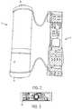
- FIG. 1is a top plan view of a battery cell and a reusable battery indicator constructed in accordance with the teachings of the disclosure, the battery cell and the reusable battery indicator being separated from one another.
- FIG. 2is a top plan view of the reusable battery indicator of FIG. 1 connected to the battery cell.
- FIG. 3is a close-up plan view of a printed circuit board of the reusable battery indicator of FIG. 1 .
- FIG. 4is an electronic circuit schematic diagram of the reusable battery indicator of FIG. 1 .
- FIGS. 5A and 5Bare top and bottom perspective views, respectively, of a second embodiment of a reusable battery indicator that is connected to a battery cell.
- FIG. 6is a top perspective view of a third embodiment of a reusable battery indicator that is connected to a battery cell.
- FIGS. 7A and 7Bare top and bottom perspective views, respectively, of a fourth embodiment of a reusable battery indicator that is connected to a battery cell.
- FIGS. 8A and 8Bare top and bottom perspective views, respectively, of a fifth embodiment of a reusable battery indicator that is connected to a battery cell.
- FIG. 9is a close-up cross-sectional view of a negative radial leaf at one end of the reusable battery indicator of FIGS. 8A and 8B .
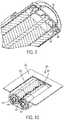
- FIG. 10is a bottom perspective view of a battery compartment of an electronic device including two battery cells and a sixth embodiment of a reusable battery indicator that is connected to one of the battery cells.
- FIG. 11is an end view of a seventh embodiment of a reusable battery indicator that is attached to one cell of a pair of battery cells.
- FIG. 12is a diagram of a eighth embodiment of a reusable battery indicator that is located between two adjacent battery cells.
- FIG. 13is a schematic diagram of a battery indication system including the reusable battery indicator of FIG. 1 .
- FIG. 14Ais a perspective view of a ninth embodiment reusable battery indicator and a battery cell.
- FIG. 14Bis side cross-sectional view of the reusable battery indicator and battery cell of FIG. 14A .
- Electrochemical cells, or batteriesmay be primary or secondary.
- Primary batteriesare meant to be discharged, e.g., to exhaustion, only once and then discarded.
- Primary batteriesor disposable batteries
- Secondary batteriesor rechargeable batteries
- Secondary batteriesare intended to be recharged and used over and over again.
- Secondary batteriesmay be discharged and recharged many times, e.g., more than fifty times, a hundred times, or more.
- Secondary batteriesare described, for example, in David Linden, Handbook of Batteries (4 th ed. 2011). Accordingly, batteries may include various electrochemical couples and electrolyte combinations.
- a primary alkaline electrochemical cell, or battery cell 10that includes a cathode 12 , an anode 14 , and a housing 18 .
- the battery cell 10also includes an end cap 24 .
- the end cap 24serves as a negative terminal of the battery cell 10 .
- a positive pip 26is located at the opposite end of the battery cell 10 from the end cap 24 .
- the positive pip 26serves as a positive terminal of the battery cell 10 .
- An electrolytic solutionis dispersed throughout the battery cell 10 .
- the battery cell 10can be, for example, a AA, AAA, AAAA, C, or D alkaline battery. Additionally, in other embodiments, the battery cell 10 can be a 9V battery, a camera battery, a watch battery, or any other type of primary or secondary battery.
- the housing 18can be made of any suitable type of housing base material, for example cold-rolled steel or nickel-plated cold-rolled steel.
- the housing 18may have a cylindrical shape.
- the housing 18may have any other suitable, non-cylindrical shape.
- the housing 18may have a shape comprising at least two parallel plates, such as a rectangular, square, or prismatic shape.
- the housing 18may be, for example, deep-drawn from a sheet of the base material, such as cold-rolled steel or nickel-plated steel.
- the housing 18may be, for example, drawn into a cylindrical shape.
- the housing 18may have a sidewall.
- the interior surface of the sidewall of the housing 18may be treated with a material that provides a low electrical-contact resistance between the interior surface of the sidewall of the housing 18 and an electrode, such as the cathode 12 .
- the interior surface of the sidewall of the housing 18may be plated, e.g., with nickel, cobalt, and/or painted with a carbon-loaded paint to decrease contact resistance between, for example, the internal surface of the sidewall of the housing 18 and the cathode 12 .
- the reusable battery indicator 40includes an integrated circuit, which may be incorporated into a printed circuit board (PCB) 42 , a first connector 44 that is electrically connected to the PCB 42 , and a second connector 46 that is electrically connected to the PCB 42 .
- the first connector 44may be removably and electrically connected to the positive pip 26 to form a positive electrical connection and the second connector 46 may be removably and electrically connected to the end cap 24 to form a negative electrical connection, as illustrated in FIG. 2 .
- the first connector 44 and the second connector 46may take virtually any physical form that allows the first connector 44 and the second connector 46 to form electrical connections with the battery cell 10 and the PCB 42 .
- the first connector 44 and the second connector 46may take any one or more of the following forms, a magnet, a cup, a sleeve, a tab, a socket, a pin, a washer, a spring connector, a wire loop, or any combination thereof.
- the first connector 44 and the second connector 46may be formed from virtually any material that transmits analog information, such as electrical information, from the battery cell to the PCB 42 .
- the first connector 44 and the second connector 46may be formed from one or more of the following materials, a metal, a metal alloy, cold-rolled steel, hard drawn ferrous and non-ferrous alloys, high and low carbon steel alloys, post or pre-plated ferrous and non-ferrous alloys, or any combination thereof.
- at least one of the first connector 44 and the second connector 46may comprise a metal and an insulator.
- an inner surface of the first and second connectors 44 , 46may include a non-conductive coating (such as a polymer layer, epoxy, or passivate) or an additional insulator ring (e.g., paper, phenolic, or polymer) in areas other than contact areas for the terminals to guard against shorting to the battery housing or crimp.
- a non-conductive coatingsuch as a polymer layer, epoxy, or passivate
- an additional insulator ringe.g., paper, phenolic, or polymer
- the integrated circuitreceives electrical information, such as amperes or volts from the first connector 44 and from the second connector 46 , and the electrical information is used by the integrated circuit to calculate battery characteristic information, such as power or charge level, and the integrated circuit then transmits the battery characteristic information to a receiver, such as a computer, a smart phone, or a personal digital assistant, for use by the consumer.
- a receiversuch as a computer, a smart phone, or a personal digital assistant
- the reusable battery indicator 40allows a consumer to acquire the battery characteristic information without removing the battery cell from an electronic device (or from a package).
- the first connector 44 and the second connector 46deliver the electrical information to the integrated circuit without interfering with electrical contacts between the battery cell and the electronic device.
- the reusable battery indicator 40is movable from one battery cell to another battery cell so as to be reused over and over again, thereby reducing the overall cost to a consumer.
- an integrated circuit 48formed on the PCB 42 is an integrated circuit 48 , that includes an embedded voltage sensor 50 within the integrated circuit 48 that is communicatively connected to the first connector 44 and to the second connector 46 .
- the embedded voltage sensor 50senses analog characteristics of the battery cell, such as amperes and voltage and converts the sensed analog characteristics to digital information.
- the PCB 42also includes a communication circuit 52 .
- An antenna 54is operatively coupled to the communication circuit 52 .
- the communication circuit 52may comprise one or more of a radio-frequency identification circuit, a Bluetooth® circuit, a Bluetooth® low energy circuit, a Wi-Fi circuit, a Zigbee® circuit, a LORA circuit, and a Z-wave circuit.
- an integrated circuitsuch as a wireless Bluetooth Low-Energy voltage sensor, may incorporate the analog to digital converter, a microcontroller, a Bluetooth radio, a memory device, and a DC/DC voltage converter.
- a voltage booster 56is electrically connected to the integrated circuit 48 and the embedded voltage sensor 50 .
- the embedded voltage sensor 50 and the voltage booster 56are capable of reading the open circuit voltage of the battery that may be, for example, less than 1.8 volts.
- the communication circuit 52may comprise one or more of a thin disc BLE module, a UHF module, or a RF module.
- the integrated circuit 48 , the voltage sensor 50 , and the communication circuit 52are all formed on the PCB 42 , which is connected to the first connector 44 and the second connector 46 .
- the integrated circuit 48 , the voltage sensor 50 , and the communication circuit 52may be formed as separate components that are communicatively and operatively connected to one another.
- FIGS. 5A and 5Bsimilar elements are numbered exactly 100 greater than elements numbered in FIGS. 1-4 .
- the battery cellis numbered 10 in FIGS. 1-4 and the battery cell is numbered 110 in FIGS. 5A and 5B .
- any element from any illustrated embodimentmay be incorporated into any other illustrated embodiment.
- the reusable battery indicator 140includes a PCB 142 , a first connector 144 , and a second connector 146 . While the battery cell 110 in FIGS. 5A and 5B is illustrated as a AA size battery, the illustration is not intended to limit the reusable battery indicator 140 to the illustrated battery cell 110 . Rather, the reusable battery indicator 140 may be sized and shaped to fit virtually any battery cell, especially those battery cell sizes listed elsewhere in the specification.
- the first connector 144 and the second connector 146comprise flexible wires 160 , 162 , respectively.
- the flexible wires 160 , 162may be formed as spring wires (from hard drawn ferrous and non-ferrous spring alloys) that capture the positive battery terminal 126 and the negative battery terminal 124 , respectively, to transmit electrical characteristics, such as voltage and amperes, to the integrated circuit formed on the PCB 142 .
- the flexible wires 160 , 162are formed of ASTM A228 music wire with pre or post nickel plating to enhance conductivity, to reduce contact resistance, and to provide corrosion resistance.
- the flexible wire 160includes a first end 166 , which is connected to a positive terminal 168 on the PCB 142 and a second end 170 , which is also connected to the positive terminal 168 on the PCB 142 .
- the flexible wire 160includes a first leg 172 , extending from the first end 166 and a second leg 174 extending from the second end 170 .
- the first leg 172 and the second leg 174are oriented substantially parallel to a longitudinal axis A of the battery cell 110 .
- the first leg 172 and the second leg 174are connected to one another at an end loop 176 .
- the end loop 176lies in a plane that is substantially perpendicular to the longitudinal axis of the battery cell 110 .
- the end loop 176is sized and shaped to fit around the positive terminal 126 of the battery cell 110 .
- the flexible wire 160forms a positive electrical pathway from the positive battery terminal 126 to the positive terminal 168 on the PCB 142 .
- the flexible wire 160may be formed to produce a spring force that biases the flexible wire 160 into the attached position illustrated in FIGS. 5A and 5B , while allowing the flexible wire 160 to be temporarily deformed by a user to remove the reusable battery indicator 140 from the battery cell 110 when desired.
- the flexible wire 162includes a first end 178 , which is connected to a negative terminal 180 on the PCB 142 and a second end 182 , which is also connected to the negative terminal 180 on the PCB 142 .
- the flexible wire 162includes a first leg 184 , extending from the first end 178 and a second leg 186 extending from the second end 182 .
- the first leg 184 and the second leg 186are oriented substantially parallel to the longitudinal axis A of the battery cell 110 .
- the first leg 184 and the second leg 186are connected to one another at an end loop 188 .
- the end loop 188lies in a plane that is substantially perpendicular to the longitudinal axis of the battery cell 110 .
- the end loop 186is sized and shaped to fit around the negative terminal 124 of the battery cell 110 .
- the flexible wire 162forms a negative electrical pathway from the negative battery terminal 124 to the negative terminal 180 on the PCB 142 .
- the flexible wire 162may be formed to produce a spring force that biases the flexible wire 162 into the attached position illustrated in FIGS. 5A and 5B , while allowing the flexible wire 162 to be temporarily deformed by a user to remove the reusable battery indicator 140 from the battery cell 110 when desired.
- the bendsmay be more than 90° to mate to a tapered positive terminal.
- one or more of the first flexible wire 160 and the second flexible wire 162may include a conductive magnet, or the one or more of the first flexible wire 160 and the second flexible wire 162 may be formed from conductive magnetic material, to provide additional retention force between the first flexible wire 160 and the positive terminal 126 and between the second flexible wire 162 and the negative terminal 124 .
- first flexible wire 160 and the second flexible wire 162may be formed as a Kelvin connection, including separate power and sensing terminals, to measure impedance. Additionally, in alternate embodiments, the first flexible wire 160 and the second flexible wire 162 need not be formed as a single continuous wire, but may be formed as multiple wire pieces, for example, two wire pieces that are separated by a small distance in the end loop.
- FIGS. 5A and 5Bin the embodiment of FIG. 6 , similar elements are numbered exactly 100 greater than elements numbered in FIGS. 1-4 .
- the battery cellis numbered 10 in FIGS. 1-4 and the battery cell is numbered 110 in FIG. 6 .
- any element from any illustrated embodimentmay be incorporated into any other illustrated embodiment.
- the reusable battery indicator 140includes a PCB 142 , a first connector 144 , and a second connector 146 . While the battery cell 110 in FIG. 6 is illustrated as a AA size battery, the illustration is not intended to limit the reusable battery indicator 140 to the illustrated battery cell 110 . Rather, the reusable battery indicator 140 may be sized and shaped to fit virtually any battery cell, especially those battery cell sizes listed elsewhere in the specification.
- the first connector 144 and the second connector 146comprise flexible wires 160 , 162 , respectively.
- the flexible wires 160 , 162may be formed as spring wires that capture the positive battery terminal 126 and the negative battery terminal 124 , respectively, to transmit electrical characteristics, such as voltage and amperes, to the integrated circuit formed on the PCB 142 .
- the flexible wires 160 , 162 in FIG. 6are similar to the flexible wires of FIGS. 5A and 5B , except that the flexible wires 160 , 162 in FIG. 6 have only a single leg. More specifically, the flexible wire 160 includes a first end 166 , which is connected to a positive terminal 168 on the PCB 142 . The flexible wire 160 includes a single leg 172 , extending from the first end 166 . The single leg 172 is oriented substantially parallel to a longitudinal axis A of the battery cell 110 . The single leg 172 forms an end loop 176 at a second end. The end loop 176 lies in a plane that is substantially perpendicular to the longitudinal axis of the battery cell 110 .
- the end loopalso lies below the plane of the contact surface of the positive terminal 126 . In this manner, the end loop 176 does not interfere with an electronic device making contact with the positive terminal 126 .
- the end loop 176is sized and shaped to fit around the positive terminal 126 of the battery cell 110 .
- the flexible wire 160forms a positive electrical pathway from the positive battery terminal 126 to the positive terminal 168 on the PCB 142 .
- the flexible wire 160may be formed to produce a spring force that biases the flexible wire 160 into the attached position illustrated in FIG. 6 , while allowing the flexible wire 160 to be temporarily deformed by a user to remove the reusable battery indicator 140 from the battery cell 110 when desired.
- the flexible wire 162includes a first end 178 , which is connected to a negative terminal 180 on the PCB 142 .
- the flexible wire 162includes a single leg 184 , extending from the first end 178 .
- the single leg 184is oriented substantially parallel to the longitudinal axis A of the battery cell 110 .
- the single leg 184forms an end loop 188 at a second end.
- the end loop 188lies in a plane that is substantially perpendicular to the longitudinal axis of the battery cell 110 .
- the end loop 188also lies below the plane of the contact surface of the negative terminal 124 . In this manner, the end loop 188 does not interfere with an electronic device making contact with the negative terminal 124 .
- the end loop 188is sized and shaped to fit around the negative terminal 124 of the battery cell 110 .
- the flexible wire 162forms a negative electrical pathway from the negative battery terminal 124 to the negative terminal 180 on the PCB 142 .
- the flexible wire 162may be formed to produce a spring force that biases the flexible wire 162 into the attached position illustrated in FIG. 6 , while allowing the flexible wire 162 to be temporarily deformed by a user to remove the reusable battery indicator 140 from the battery cell 110 when desired.
- one or more of the first flexible wire 160 and the second flexible wire 162may include a conductive magnet, or the one or more of the first flexible wire 160 and the second flexible wire 162 may be formed from conductive magnetic material, to provide additional retention force between the first flexible wire 160 and the positive terminal 126 and between the second flexible wire 162 and the negative terminal 124 .
- one or more of the first flexible wire 160 and the second flexible wire 162may be formed as a Kelvin connection, including separate power and sensing terminals, to measure impedance.
- FIGS. 7A and 7Bsimilar elements are numbered exactly 200 greater than elements numbered in FIGS. 1-4 .
- the battery cellis numbered 10 in FIGS. 1-4 and the battery cell is numbered 210 in FIGS. 7A and 7B .
- any element from any illustrated embodimentmay be incorporated into any other illustrated embodiment.
- the reusable battery indicator 240includes a PCB 242 , a first connector 244 , and a second connector 246 . While the battery cell 210 in FIGS. 6A and 6B is illustrated as a AA size battery, the illustration is not intended to limit the reusable battery indicator 240 to the illustrated battery cell 210 . Rather, the reusable battery indicator 240 may be sized and shaped to fit virtually any battery cell, especially those battery cell sizes listed elsewhere in the specification.
- the first connector 244 and the second connector 246comprise leaf springs 260 , 262 , respectively.
- the leaf springs 260 , 262may be formed as planar legs that capture the positive battery terminal 226 and the negative battery terminal 224 , respectively, to transmit electrical characteristics, such as voltage and amperes, to the integrated circuit formed on the PCB 142 .
- the leaf spring 260includes a first end 266 , which is connected to a positive terminal 268 on the PCB 242 .
- the leaf spring 260includes a first leg 272 , extending from the first end 266 .
- the first leg 272is substantially planar (or very slightly curved to mirror the curvature of the outer surface of the battery cell 210 ) and is oriented substantially parallel to the longitudinal axis of the battery cell 210 .
- the first leg 272turns approximately 90° near a second end 273 , forming an end clip 276 .
- the end clip 276lies in a plane that is substantially perpendicular to the longitudinal axis of the battery cell 210 .
- the end clip 276includes a concave end that is curved to mirror an outer cylindrical surface of the positive terminal 226 of the battery cell 210 .
- the leaf spring 260forms a positive electrical pathway from the positive battery terminal 226 to the positive terminal 268 on the PCB 242 .
- the leaf spring 260may be formed to produce a spring force that biases the leaf spring 260 into the attached position illustrated in FIGS. 7A and 7B , while allowing the leaf spring 260 to be temporarily deformed by a user to remove the reusable battery indicator 240 from the battery cell 210 when desired.
- the leaf spring 262includes a first end 278 , which is connected to a negative terminal 280 on the PCB 242 .
- the leaf spring 262includes a first leg 284 , extending from the first end 278 .
- the first leg 284is substantially planar (or very slightly curved to mirror the curvature of the outer surface of the battery cell 210 ) and is oriented substantially parallel to a longitudinal axis of the battery cell 210 .
- the first leg 284turns approximately 90° near a second end 285 , forming an end clip 288 .
- the end clip 288lies in a plane that is substantially perpendicular to the longitudinal axis of the battery cell 210 .
- the end clip 288includes a concave end that is curved to mirror an outer cylindrical surface of the negative terminal 224 of the battery cell 210 .
- the leaf spring 262forms a negative electrical pathway from the negative battery terminal 224 to the negative terminal 280 on the PCB 242 .
- the leaf spring 262may be formed to produce a spring force that biases the leaf spring 262 into the attached position illustrated in FIGS. 7A and 7B , while allowing the leaf spring 262 to be temporarily deformed by a user to remove the reusable battery indicator 240 from the battery cell 210 when desired.
- one or more of the first leaf spring 260 and the second leaf spring 262may be integrated into the positive terminal 268 and the negative terminal 280 , respectively, of the PCB 242 as one layer of a multi-layered PCB 242 .
- the reusable battery indicator 240may also include a retention clip 291 that extends from the reusuable battery indicator 240 in a plane substantially perpendicular to the longitudinal axis of the battery cell 210 .
- the retention clip 291may include two opposing legs that are curved to mirror the curvature of the outer surface of the battery cell 210 .
- the retention clip 291provides additional retention force to retain the reusable battery indicator 240 on the battery cell 210 .
- FIGS. 8A, 8B, and 9similar elements are numbered exactly 300 greater than elements numbered in FIGS. 1-4 .
- the battery cellis numbered 10 in FIGS. 1-4 and the battery cell is numbered 310 in FIGS. 8A, 8B, and 9 .
- any element from any illustrated embodimentmay be incorporated into any other illustrated embodiment.
- the reusable battery indicator 340includes a PCB 342 , a first connector 344 , and a second connector 346 . While the battery cell 210 in FIGS. 8A and 8B is illustrated as a AA size battery, the illustration is not intended to limit the reusable battery indicator 340 to the illustrated battery cell 310 . Rather, the reusable battery indicator 340 may be sized and shaped to fit virtually any battery cell, especially those battery cell sizes listed elsewhere in the specification.
- the first connector 344 and the second connector 346comprise first and second leaf springs 360 , 362 , respectively.
- the first and second leaf springs 360 , 362are similar to the first and second leaf springs 260 , 262 of FIGS. 7A and 7B , with the following exceptions.
- the first leaf spring 360includes a retention clip 391 that extends in a plane that is substantially perpendicular to the longitudinal axis of the battery cell 310 .
- the second leaf spring 362may include a similar retention clip.
- the retention clip 391may include two opposing legs that are curved to mirror the curvature of the outer surface of the battery cell 310 .
- the retention clip 391provides additional retention force to retain the reusable battery indicator 340 on the battery cell 310 .
- the second leaf spring 346includes an end loop 388 .
- the end loop 388lies in a plane that is substantially perpendicular to the longitudinal axis of the battery cell 310 .
- the end loop 388includes an inner opening 392 that is sized and shaped to mirror an outer cylindrical surface of the negative battery terminal 324 .
- the second leaf spring 362forms a negative electrical pathway from the negative battery terminal 324 to the negative terminal on the PCB 342 .
- the end loop 388may include a disc-shaped voltage sensor that is arranged to fit one end of the cylindrical battery cell 310 .
- the end loop 388may include a radial collar 394 that extends away from the end loop 388 , towards the PCB 342 .
- the radial collar 394is sized and shaped to fit within a negative cap recess 396 .
- the radial collar 394provides negative terminal location and contact force, in addition to the end loop 388 .
- a similar end loop with a radial collarmay be formed in the first leaf spring for contact at the positive battery terminal.
- the radial collarmay provide additional clearance at the positive battery terminal where a reverse polarity insertion guard exists.
- the end loop 388 and radial collar 394cooperate with battery cells having a negative cap/positive crimp groove.
- the reusable battery indicatorincludes a housing 498 , the integrated circuit, the voltage sensor, and the communication circuit being mounted within the housing 498 .
- the housing 498is sized and shaped to fit between two cylindrical battery cells 410 that are arranged longitudinally side-by-side.
- the housing 498has a cross-section that is in the shape of a triangular prism. More specifically, the housing 498 has a first side 497 that is concave and a second side 499 that is concave.
- the housing 498may have a shape such as rectangular, trapezoid, elliptical, semi-circular, and variable, that fits within the void described by the triangular prism.
- the reusable battery indicator 440is mounted between the battery cells 410 and within a battery receptacle 495 of an electronic device 500 .
- FIG. 11a seventh embodiment of a reusable battery indicator 540 is illustrated and located between two battery cells 510 .
- the reusable battery indicator 540includes a housing 598 that has only a single concave side.
- FIG. 12illustrates an alternative housing shape.
- the housing 698is arranged to fit in the void formed by two cylindrical battery cells 610 that are arranged side by side and oriented such that the respective longitudinal axes of the battery cells 610 are parallel to one another.
- a vis the cross-sectional area of the housing 698 ;
- D Bis a diameter of one battery cell 610 .
- a housing having a cross-sectional shape defined by the preceding equationmaximizes the usable space between the battery cells.
- a housing having the cross-sectional shape defined abovewould result in the following housing volumes for the given battery sizes (assuming that the housing length was equal to the battery cell length).
- the housingwould have a volume of 526 mm 3 ; and for a AA battery, the housing would have a volume of 1140 mm 3 .
- a computing device 800is communicatively connected to the communication circuit in the reusable battery indicator 740 .
- the computing devicereceives information from the communication circuit through wireless signals sent by the antenna in the reusable battery indicator 740 .
- the wireless signalmay be one or more of a wifi signal, a Bluetooth® signal, a RFID signal, or any other wireless signal.
- the computing device 800 and the reusable battery indicator 740may communicatively connected by a wired connection.
- the computing device 800includes a processor 802 and a memory 804 .
- the memory 804may store processor executable instructions that when executed by the processor 802 cause the processor 802 to detect a wireless communication signal from the reusable battery indicator 740 .
- the memory 804may comprise a non-transitory computer readable medium with the processor executable instructions embedded thereon as an article of manufacture.
- the processor executable instructionsmay also cause the processor 802 to send wireless signals back to the reusable battery indicator 740 to remotely control battery circuitry through the reusable battery indicator 740 . In this manner, the processor 802 may cause the reusable battery indicator 740 to determine battery characteristic data; and to send the battery characteristic data to a user interface, such as a display 806 on the computing device 800 .
- the battery characteristic datamay comprise at least one of an electrical capacity; a voltage; an impedance, a temperature, a current; an age, a charge/discharge cycle count, and a coulomb count.
- the processor executable instructionswhen executed by the processor 802 , causes the processor 802 to determine at least one of a battery type, a physical location of the battery, and an electrical device that the battery is powering by communicating with the reusuable battery indicator 740 .
- the reusable battery indicator 940includes a first connector 944 and a second connector 946 .
- the first connector 944connects to the negative terminal 924 of the battery 910 and the second connector 946 connects to the positive terminal of the battery 910 .
- the first connector 944includes an insulated leg 905 with an embedded wire 907 .
- the insulated leg 905includes an inner portion 909 that prevents the embedded wirer 907 from making contact with the crimped wall 961 of the battery housing 918 .
- the embedded wire 907is exposed at a radially inward end of the insulated leg 905 so that the embedded wire 907 may make electrical contact with the negative terminal 924 , thus completing the electrical connection.
Landscapes
- Engineering & Computer Science (AREA)
- Manufacturing & Machinery (AREA)
- General Chemical & Material Sciences (AREA)
- Electrochemistry (AREA)
- Chemical Kinetics & Catalysis (AREA)
- Chemical & Material Sciences (AREA)
- Signal Processing (AREA)
- Physics & Mathematics (AREA)
- Computer Networks & Wireless Communication (AREA)
- General Physics & Mathematics (AREA)
- Microelectronics & Electronic Packaging (AREA)
- General Health & Medical Sciences (AREA)
- Medical Informatics (AREA)
- Computing Systems (AREA)
- Health & Medical Sciences (AREA)
- Battery Mounting, Suspending (AREA)
- Secondary Cells (AREA)
- Tests Of Electric Status Of Batteries (AREA)
Abstract
Description
Av=(DB2−Π/4×DB2)/2, where
Claims (20)
Priority Applications (8)
| Application Number | Priority Date | Filing Date | Title |
|---|---|---|---|
| US15/340,757US10608293B2 (en) | 2016-11-01 | 2016-11-01 | Dual sided reusable battery indicator |
| CN201780068058.1ACN109891664B (en) | 2016-11-01 | 2017-11-01 | Double-side reusable battery indicator |
| JP2019522300AJP7134954B2 (en) | 2016-11-01 | 2017-11-01 | Double-sided reusable battery indicator |
| PCT/US2017/059472WO2018085350A1 (en) | 2016-11-01 | 2017-11-01 | Dual sided reusable battery indicator |
| AU2017355393AAU2017355393B2 (en) | 2016-11-01 | 2017-11-01 | Dual sided reusable battery indicator |
| EP17800664.9AEP3535801B1 (en) | 2016-11-01 | 2017-11-01 | Dual sided reusable battery indicator |
| US16/834,827US11024892B2 (en) | 2016-11-01 | 2020-03-30 | Dual sided reusable battery indicator |
| US17/135,759US11664539B2 (en) | 2016-11-01 | 2020-12-28 | Dual sided reusable battery indicator |
Applications Claiming Priority (1)
| Application Number | Priority Date | Filing Date | Title |
|---|---|---|---|
| US15/340,757US10608293B2 (en) | 2016-11-01 | 2016-11-01 | Dual sided reusable battery indicator |
Related Child Applications (1)
| Application Number | Title | Priority Date | Filing Date |
|---|---|---|---|
| US16/834,827ContinuationUS11024892B2 (en) | 2016-11-01 | 2020-03-30 | Dual sided reusable battery indicator |
Publications (2)
| Publication Number | Publication Date |
|---|---|
| US20180123175A1 US20180123175A1 (en) | 2018-05-03 |
| US10608293B2true US10608293B2 (en) | 2020-03-31 |
Family
ID=60382611
Family Applications (3)
| Application Number | Title | Priority Date | Filing Date |
|---|---|---|---|
| US15/340,757Active2038-03-31US10608293B2 (en) | 2016-11-01 | 2016-11-01 | Dual sided reusable battery indicator |
| US16/834,827ActiveUS11024892B2 (en) | 2016-11-01 | 2020-03-30 | Dual sided reusable battery indicator |
| US17/135,759Active2037-02-20US11664539B2 (en) | 2016-11-01 | 2020-12-28 | Dual sided reusable battery indicator |
Family Applications After (2)
| Application Number | Title | Priority Date | Filing Date |
|---|---|---|---|
| US16/834,827ActiveUS11024892B2 (en) | 2016-11-01 | 2020-03-30 | Dual sided reusable battery indicator |
| US17/135,759Active2037-02-20US11664539B2 (en) | 2016-11-01 | 2020-12-28 | Dual sided reusable battery indicator |
Country Status (6)
| Country | Link |
|---|---|
| US (3) | US10608293B2 (en) |
| EP (1) | EP3535801B1 (en) |
| JP (1) | JP7134954B2 (en) |
| CN (1) | CN109891664B (en) |
| AU (1) | AU2017355393B2 (en) |
| WO (1) | WO2018085350A1 (en) |
Cited By (3)
| Publication number | Priority date | Publication date | Assignee | Title |
|---|---|---|---|---|
| US10992327B2 (en)* | 2018-09-12 | 2021-04-27 | Contemporary Amperex Technology Co., Limited | Wireless radio frequency communication system |
| US11265828B2 (en)* | 2019-08-21 | 2022-03-01 | Qualcomm Incorporated | Power allocation for sidelink feedback transmission |
| US11664539B2 (en)* | 2016-11-01 | 2023-05-30 | Duracell U.S. Operations, Inc. | Dual sided reusable battery indicator |
Families Citing this family (18)
| Publication number | Priority date | Publication date | Assignee | Title |
|---|---|---|---|---|
| US9551758B2 (en) | 2012-12-27 | 2017-01-24 | Duracell U.S. Operations, Inc. | Remote sensing of remaining battery capacity using on-battery circuitry |
| US9478850B2 (en) | 2013-05-23 | 2016-10-25 | Duracell U.S. Operations, Inc. | Omni-directional antenna for a cylindrical body |
| US9726763B2 (en) | 2013-06-21 | 2017-08-08 | Duracell U.S. Operations, Inc. | Systems and methods for remotely determining a battery characteristic |
| US9882250B2 (en) | 2014-05-30 | 2018-01-30 | Duracell U.S. Operations, Inc. | Indicator circuit decoupled from a ground plane |
| US10297875B2 (en) | 2015-09-01 | 2019-05-21 | Duracell U.S. Operations, Inc. | Battery including an on-cell indicator |
| US11024891B2 (en) | 2016-11-01 | 2021-06-01 | Duracell U.S. Operations, Inc. | Reusable battery indicator with lock and key mechanism |
| US10483634B2 (en) | 2016-11-01 | 2019-11-19 | Duracell U.S. Operations, Inc. | Positive battery terminal antenna ground plane |
| US10818979B2 (en) | 2016-11-01 | 2020-10-27 | Duracell U.S. Operations, Inc. | Single sided reusable battery indicator |
| US10151802B2 (en) | 2016-11-01 | 2018-12-11 | Duracell U.S. Operations, Inc. | Reusable battery indicator with electrical lock and key |
| KR102274412B1 (en)* | 2019-01-24 | 2021-07-07 | 주식회사 엘지에너지솔루션 | Battery characteristics measuring apparatus |
| CN110116623B (en)* | 2019-04-30 | 2022-06-24 | 蜂巢能源科技有限公司 | Connection failure detection method and battery management system of power battery pack |
| USD936568S1 (en)* | 2020-01-07 | 2021-11-23 | ShenZhen Mobai Technology Limited | Battery |
| USD941751S1 (en)* | 2020-01-16 | 2022-01-25 | Streamlight, Inc. | Battery with charging port and key way |
| USD949095S1 (en)* | 2020-08-14 | 2022-04-19 | Streamlight, Inc. | Battery with charging port and key way |
| US11837754B2 (en) | 2020-12-30 | 2023-12-05 | Duracell U.S. Operations, Inc. | Magnetic battery cell connection mechanism |
| US11639789B2 (en) | 2021-01-13 | 2023-05-02 | Streamlight, Inc. | Portable light and keyed rechargeable USB battery |
| JP7333803B2 (en)* | 2021-06-29 | 2023-08-25 | ソフトバンク株式会社 | Power supply and power system |
| WO2024020916A1 (en)* | 2022-07-28 | 2024-02-01 | 宁德时代新能源科技股份有限公司 | Sampling apparatus, battery, and electrical device |
Citations (320)
| Publication number | Priority date | Publication date | Assignee | Title |
|---|---|---|---|---|
| US3354565A (en) | 1966-02-01 | 1967-11-28 | Texas Instruments Inc | Passive information displays |
| US3992228A (en) | 1974-10-31 | 1976-11-16 | Saft-Societe Des Accumulateurs Fixes Et De Traction | Electric primary cell comprising a visual indicator of its state of charge |
| US3993985A (en) | 1973-05-10 | 1976-11-23 | Ebauches S.A. | Indicator for the condition of a battery operating a timepiece |
| JPS525581A (en) | 1975-07-02 | 1977-01-17 | Hitachi Ltd | Voltage detector circuit |
| US4117475A (en) | 1975-12-01 | 1978-09-26 | Citizen Watch Company Limited | Driver circuit for electrochromic display device |
| US4149146A (en) | 1976-02-09 | 1979-04-10 | Citizen Watch Company Limited | Driver circuit for electrochromic display device |
| US4238554A (en) | 1979-09-04 | 1980-12-09 | Duracell International Inc. | Abuse resistant active metal anode/fluid cathode depolarized cells |
| US4302751A (en) | 1976-08-20 | 1981-11-24 | Sharp Kabushiki Kaisha | Driver circuit for electrochromic displays |
| US4460870A (en) | 1981-07-23 | 1984-07-17 | Curtis Instruments, Inc. | Quiescent voltage sampling battery state of charge meter |
| US4482615A (en) | 1982-09-30 | 1984-11-13 | Power Conversion, Inc. | Lithium anode comprising copper strip in contact with lithium body and lithium-sulfur dioxide battery utilizing same |
| US4598243A (en) | 1983-12-06 | 1986-07-01 | Fuji Photo Film Co., Ltd. | Direct-current power supply with alarm indicator |
| JPS61169781A (en) | 1985-01-23 | 1986-07-31 | Canon Inc | image forming device |
| US4654280A (en) | 1984-12-27 | 1987-03-31 | Eveready Battery Company | Nonaqueous cell employing a cathode-electrolyte solution containing a boron-containing additive |
| US4759765A (en) | 1986-03-17 | 1988-07-26 | Minnesota Mining And Manufacturing Company | Tissue augmentation device |
| US4808497A (en) | 1983-12-28 | 1989-02-28 | Eveready Battery Company | Organic electrolyte for nonaqueous cells |
| US4860185A (en) | 1987-08-21 | 1989-08-22 | Electronic Research Group, Inc. | Integrated uninterruptible power supply for personal computers |
| JPH02142324A (en) | 1988-11-19 | 1990-05-31 | Fukuda Denshi Co Ltd | Residual capacity indicator for battery |
| US4952330A (en) | 1989-05-25 | 1990-08-28 | Eveready Battery Company, Inc. | Nonaqueous electrolyte |
| US5015544A (en) | 1989-02-08 | 1991-05-14 | Strategic Energy Ltd. | Battery with strength indicator |
| JPH03131771A (en) | 1989-10-17 | 1991-06-05 | Seikosha Co Ltd | Battery voltage detecting device |
| US5032825A (en) | 1990-03-02 | 1991-07-16 | Motorola, Inc. | Battery capacity indicator |
| EP0523901A1 (en) | 1991-07-16 | 1993-01-20 | Duracell Inc. | Battery with integral condition tester |
| US5188231A (en) | 1991-05-31 | 1993-02-23 | Duracell Inc. | Battery package with removable voltage indicator means |
| US5200686A (en)* | 1991-10-10 | 1993-04-06 | Motorola, Inc. | Method and apparatus for determining battery type |
| US5219683A (en) | 1990-08-02 | 1993-06-15 | Eveready Battery Company, Inc. | Diol diesters and alkoxyalkylesters as solvents for nonaqueous battery electrolytes |
| US5231356A (en) | 1992-06-16 | 1993-07-27 | Robert Parker | Flexible battery tester with a variable length resistive heater |
| US5250905A (en) | 1991-09-24 | 1993-10-05 | Duracell Inc. | Battery with electrochemical tester |
| US5290414A (en) | 1992-05-15 | 1994-03-01 | Eveready Battery Company, Inc. | Separator/electrolyte combination for a nonaqueous cell |
| CN1084281A (en) | 1992-09-14 | 1994-03-23 | M&C株式会社 | Battery inspection method and device |
| US5355089A (en) | 1992-07-22 | 1994-10-11 | Duracell Inc. | Moisture barrier for battery with electrochemical tester |
| US5366832A (en) | 1992-06-01 | 1994-11-22 | Kuraray Co., Ltd. | Separator for alkaline batteries |
| WO1995001062A1 (en) | 1993-06-28 | 1995-01-05 | Troyk Philip R | Remote identification system for containers |
| US5389470A (en) | 1993-05-07 | 1995-02-14 | Parker; Robert | Temperature responsive battery tester |
| US5389458A (en) | 1993-05-03 | 1995-02-14 | Eveready Battery Company, Inc. | Battery with tester label and method for producing it |
| US5418086A (en) | 1993-08-09 | 1995-05-23 | Eveready Battery Company, Inc. | Battery with coulometric state of charge indicator |
| US5424722A (en) | 1991-05-13 | 1995-06-13 | Sony Corporation | Device for displaying remaining electric energy of battery |
| US5438607A (en) | 1992-11-25 | 1995-08-01 | U.S. Monitors, Ltd. | Programmable monitoring system and method |
| US5458992A (en) | 1991-01-31 | 1995-10-17 | Eveready Battery Company | Electrochromic thin film state-of-charge detector for on-the-cell application |
| US5458997A (en) | 1994-08-19 | 1995-10-17 | Medtronic, Inc. | Rebalancing of lithium/silver vandium oxide (Li/SVO) cells for improved performance |
| US5491038A (en) | 1994-08-24 | 1996-02-13 | Duracell Inc. | Contact ring for on-cell battery tester |
| US5494496A (en) | 1991-01-31 | 1996-02-27 | Eveready Battery Company, Inc. | Battery voltage tester for end of cell |
| US5514491A (en) | 1993-12-02 | 1996-05-07 | Eveready Battery Company, Inc. | Nonaqueous cell having a lithium iodide-ether electrolyte |
| US5543246A (en) | 1993-09-02 | 1996-08-06 | Duracell Inc. | Battery tester adhesive system |
| US5569556A (en) | 1994-12-30 | 1996-10-29 | Display Matrix Corporation | Battery charge indicator |
| US5587573A (en) | 1992-11-10 | 1996-12-24 | Xicor, Inc. | Wireless powering and communication system for communicating data between a host system and a stand-alone device |
| JPH095366A (en) | 1995-06-21 | 1997-01-10 | Sgs Thomson Microelectron Sa | High precision relative digital voltage measuring method and device |
| US5596278A (en) | 1995-09-08 | 1997-01-21 | Duracell Inc. | Condition tester for a battery |
| US5607790A (en) | 1994-09-29 | 1997-03-04 | Duracell Inc. | Electrochemical cell label with integrated tester |
| US5627472A (en) | 1995-01-26 | 1997-05-06 | Duracell Inc. | Condition tester for a battery |
| US5633592A (en) | 1992-12-12 | 1997-05-27 | Braun Aktiengesellschaft | Charge status indicator |
| US5640150A (en) | 1995-08-17 | 1997-06-17 | The United States Of America As Represented By The Secretary Of The Army | Resettable state-of-charge indicator for rechargeable batteries |
| US5691083A (en) | 1995-06-07 | 1997-11-25 | Eveready Battery Company, Inc. | Potassium ion additives for voltage control and performance improvement in nonaqueous cells |
| JPH1014003A (en) | 1996-06-17 | 1998-01-16 | Hino Motors Ltd | In-vehicle battery information transmission device |
| US5737114A (en) | 1991-01-31 | 1998-04-07 | Eveready Battery Company, Inc. | Label having an incorporated electrochromic state-of-charge indicator for an electrochemical cell |
| US5786106A (en) | 1996-06-24 | 1998-07-28 | Armani; Shane | Battery pack with interchangeable tag-along supplemental feature cartridge particularly for cellular telephones |
| US5925479A (en) | 1995-01-23 | 1999-07-20 | Duracell, Inc. | Moisture barrier composite film of silicon nitride and fluorocarbon polymer and its use with an on-cell tester for an electrochemical cell |
| CN1228540A (en) | 1997-12-26 | 1999-09-15 | 三星电子株式会社 | Device and method for accurately measuring battery remaining capacity |
| US5959568A (en) | 1996-06-26 | 1999-09-28 | Par Goverment Systems Corporation | Measuring distance |
| US5963012A (en) | 1998-07-13 | 1999-10-05 | Motorola, Inc. | Wireless battery charging system having adaptive parameter sensing |
| US6014014A (en) | 1998-10-28 | 2000-01-11 | Hewlett-Packard Company | State-of-charge-measurable batteries |
| JP2000077928A (en) | 1998-09-03 | 2000-03-14 | Lintec Corp | Loop antenna and data carrier |
| US6084523A (en) | 1998-07-13 | 2000-07-04 | The United States Of America As Represented By The Secretary Of The Army | Non-intrusive battery status indicator and inventory system |
| US6127062A (en) | 1998-03-24 | 2000-10-03 | Duracell Inc | End cap seal assembly for an electrochemical cell |
| US6143439A (en) | 1997-07-21 | 2000-11-07 | Duracell, Inc. | End cap assembly for an electrochemical cell |
| US6156450A (en) | 1997-07-24 | 2000-12-05 | Eveready Battery Company, Inc. | Battery tester having printed electronic components |
| US6169397B1 (en) | 1997-08-13 | 2001-01-02 | University Technology Corp. | Damped superconducting coil system having a multiturn, planar geometry superconducting coil and shunt resistors electrically connecting successive coil turns |
| US6171729B1 (en) | 1998-01-02 | 2001-01-09 | Wilson Greatbatch Ltd | Control of swelling in alkali metal electrochemical cells |
| JP2001022905A (en) | 1999-07-08 | 2001-01-26 | Hitachi Maxell Ltd | IC card device |
| US6208235B1 (en) | 1997-03-24 | 2001-03-27 | Checkpoint Systems, Inc. | Apparatus for magnetically decoupling an RFID tag |
| US6218054B1 (en) | 1991-08-13 | 2001-04-17 | Eveready Battery Company, Inc. | Dioxolane and dimethoxyethane electrolyte solvent system |
| US6252377B1 (en) | 1999-01-26 | 2001-06-26 | Honda Giken Kogyo Kabushiki Kaisha | Apparatus for detecting remaining charge of battery |
| US20010005123A1 (en) | 1999-07-22 | 2001-06-28 | Jones Brian W. | Battery monitoring system with integrated battery holder |
| US6275161B1 (en) | 1998-09-18 | 2001-08-14 | C.K. Electronics Sdn. Bhd. | Method and apparatus for automotive battery condition indication |
| CN1315072A (en) | 1998-08-28 | 2001-09-26 | 英维思能源系统(新西兰)有限公司 | Battery charge measurement and discharge reserve time prediction technique and apparatus |
| US20010026226A1 (en) | 2000-02-09 | 2001-10-04 | Olle Andersson | CMOS low battery voltage detector |
| US6300004B1 (en) | 1998-08-21 | 2001-10-09 | Eveready Battery Company, Inc. | Battery constructions having reduced collector assembly volume |
| US20020001745A1 (en) | 1998-04-02 | 2002-01-03 | Vladimir Gartstein | Battery having a built-in controller |
| US6407534B1 (en) | 2001-02-06 | 2002-06-18 | Quallion Llc | Detecting a microcurrent and a microcurrent detecting circuit |
| US20020086718A1 (en) | 1998-09-17 | 2002-07-04 | Jonathan Bigwood | Method of and an apparatus for monitoring the condition of batteries used by a mobile radio telecommunications fleet |
| DE10118051A1 (en) | 2001-04-11 | 2002-11-07 | Daimler Chrysler Ag | Battery measurement terminal with external start connection, monitors charging state of a vehicle battery by checking the total current drawn from the battery via all connections to the battery terminal |
| DE10118027A1 (en) | 2001-04-11 | 2002-11-07 | Daimler Chrysler Ag | Battery measurement terminal with external start tie lug, monitors charging state of a vehicle battery by checking the total current drawn from the battery via all connections to the battery terminal |
| US6483275B1 (en) | 1999-04-23 | 2002-11-19 | The Board Of Trustees Of The Univesity Of Illinois | Consumer battery having a built-in indicator |
| US20030070283A1 (en) | 2001-10-01 | 2003-04-17 | Eveready Battery Company, Inc. | Direct addition of beta-aminoenones in organic electrolytes of nonaqueous cells employing solid cathodes |
| WO2003047064A2 (en) | 2001-11-27 | 2003-06-05 | Xsilogy, Inc. | Remote battery monitoring systems and sensors |
| US6587250B2 (en) | 2001-03-07 | 2003-07-01 | Acreo Ab | Electrochromic device |
| US6617069B1 (en) | 1998-09-16 | 2003-09-09 | George Frederick Hopper | Battery over-discharge protection |
| US6617072B2 (en) | 2001-11-27 | 2003-09-09 | Ovonic Battery Company, Inc. | Positive active electrode composition with graphite additive |
| US20030169047A1 (en) | 2002-03-05 | 2003-09-11 | Chicony Electronics Co., Ltd. | Battery capacity detection device and method |
| US20030170537A1 (en) | 2000-06-19 | 2003-09-11 | Randell Christhoper Fred | Alkaline elctrochemical cells |
| US6627353B1 (en) | 2000-11-08 | 2003-09-30 | Lithium Power Technologies, Inc. | Disposable lithium batteries |
| US20030184493A1 (en) | 2002-04-02 | 2003-10-02 | Antoine Robinet | Multi-part reception antenna |
| US20030228518A1 (en) | 2002-06-05 | 2003-12-11 | Marple Jack W. | Nonaqueous electrochemical cell with improved energy density |
| US6670073B2 (en) | 1998-08-21 | 2003-12-30 | Eveready Battery Company, Inc. | Battery constructions having increased internal volume for active components |
| US20040029007A1 (en) | 2000-11-13 | 2004-02-12 | Sanyo Electric Co., Ltd. | Non-aqueous electrolyte battery |
| US20040048512A1 (en) | 2002-09-11 | 2004-03-11 | Carl Chen | Quick coupler for cylindrical battery terminal |
| JP2004085580A (en) | 1999-11-24 | 2004-03-18 | Seiko Epson Corp | Voltage detector |
| USRE38518E1 (en) | 1998-08-21 | 2004-05-18 | Eveready Battery Company, Inc. | Battery constructions having increased internal volume for active components |
| WO2004047215A1 (en) | 2002-11-15 | 2004-06-03 | Philips Intellectual Property & Standards Gmbh | Wireless battery management system |
| US6774685B2 (en) | 1996-05-13 | 2004-08-10 | Micron Technology, Inc. | Radio frequency data communications device |
| US6775562B1 (en) | 2000-04-17 | 2004-08-10 | Sbc Properties, Lp | Remote battery replacement notification system and method |
| EP1450174A1 (en) | 2003-02-14 | 2004-08-25 | Saft, Sa | Battery state of charge indicator |
| JP2004253858A (en) | 2003-02-18 | 2004-09-09 | Minerva:Kk | Booster antenna device for ic tag |
| US20040183742A1 (en) | 2003-02-10 | 2004-09-23 | Goff Edward D. | Multi-loop antenna for radio frequency identification (RFID) communication |
| JP2004534430A (en) | 2001-03-19 | 2004-11-11 | エスコート・メモリー・システムズ | RFID tracking method and system |
| WO2004107251A2 (en) | 2003-05-23 | 2004-12-09 | Symbol Technologies, Inc. | Rfid relay device and methods for relaying an rfid signal |
| US20050073282A1 (en) | 2003-10-03 | 2005-04-07 | Carrier David A. | Methods of discharge control for a battery pack of a cordless power tool system, a cordless power tool system and battery pack adapted to provide over-discharge protection and discharge control |
| US20050095508A1 (en) | 2003-11-05 | 2005-05-05 | Sony Corporation | Lithium-iron disulfide primary battery |
| US20050112462A1 (en) | 2003-11-21 | 2005-05-26 | Marple Jack W. | High discharge capacity lithium battery |
| US20050162129A1 (en) | 2004-01-23 | 2005-07-28 | Srdan Mutabdzija | Method and apparatus for monitoring energy storage devices |
| WO2005078673A1 (en) | 2004-02-03 | 2005-08-25 | Sys Technologies, Inc. | Remote battery monitoring system having embedded telesensors |
| US20050233214A1 (en) | 2003-11-21 | 2005-10-20 | Marple Jack W | High discharge capacity lithium battery |
| JP2005327099A (en) | 2004-05-14 | 2005-11-24 | Toshiba Tec Corp | Wireless tag reader, storage case, and article |
| US20050258797A1 (en) | 2004-05-19 | 2005-11-24 | Chien-Ming Hung | Portable emergency vehicle battery charger |
| US20050277023A1 (en) | 2003-11-21 | 2005-12-15 | Eveready Battery Company, Inc. | High discharge capacity lithium battery |
| US6979502B1 (en) | 1999-06-21 | 2005-12-27 | Board Of Trustees Of The University Of Illinois | Battery having a housing for electronic circuitry |
| US20060017581A1 (en) | 2004-07-21 | 2006-01-26 | Schwendinger Paul G | Low battery indicator |
| US20060028179A1 (en)* | 2004-07-20 | 2006-02-09 | Panasonic Ev Energy Co., Ltd. | Abnormal voltage detector apparatus for detecting voltage abnormality in assembled battery |
| US20060046152A1 (en) | 2004-08-27 | 2006-03-02 | Andrew Webber | Low temperature Li/FeS2 battery |
| US20060043933A1 (en) | 2004-08-31 | 2006-03-02 | Latinis Gary R | Battery voltage monitor |
| US20060046154A1 (en) | 2004-08-27 | 2006-03-02 | Eveready Battery Company, Inc. | Low temperature Li/FeS2 battery |
| US20060047576A1 (en) | 2004-08-30 | 2006-03-02 | Nokia Corporation | Automated memory and accessory purchasing agent for use in a mobile terminal |
| US20060046153A1 (en) | 2004-08-27 | 2006-03-02 | Andrew Webber | Low temperature Li/FeS2 battery |
| WO2006048838A1 (en) | 2004-11-08 | 2006-05-11 | Koninklijke Philips Electronics N.V. | Wireless battery status management for medical devices |
| JP2006139544A (en) | 2004-11-12 | 2006-06-01 | Seiko Epson Corp | Active RFID-TAG |
| US7067882B2 (en) | 2003-08-28 | 2006-06-27 | Lsi Logic Corporation | High quality factor spiral inductor that utilizes active negative capacitance |
| US7079079B2 (en) | 2004-06-30 | 2006-07-18 | Skycross, Inc. | Low profile compact multi-band meanderline loaded antenna |
| US20060163692A1 (en) | 2003-07-23 | 2006-07-27 | Detecheverry Celine J | Inductive and capacitvie elements for semiconductor techinologies with minimum pattern density requirements |
| US20060168802A1 (en) | 1997-10-03 | 2006-08-03 | Tuttle Mark E | Wireless identification device, RFID device with push-on/push-off switch, and method of manufacturing wireless identification device |
| US20060170397A1 (en) | 2005-01-28 | 2006-08-03 | Rengaswamy Srinivasan | Battery healty monitor |
| WO2006085291A2 (en) | 2005-02-14 | 2006-08-17 | Visible Assets, Inc. | Low frequency tag and system |
| EP1693807A1 (en) | 2001-03-19 | 2006-08-23 | Escort Memory Systems | RFID tracking method and system |
| US20060208898A1 (en) | 2005-03-04 | 2006-09-21 | Intelleflex Corporation | Compact omnidirectional RF system |
| CN2828963Y (en) | 2005-09-22 | 2006-10-18 | 中达电通股份有限公司 | Radio battery monitoring system |
| JP2006284431A (en) | 2005-04-01 | 2006-10-19 | Nissan Motor Co Ltd | Secondary battery charge rate estimation device |
| US20060247156A1 (en) | 2004-02-24 | 2006-11-02 | Ray Vanderby | Use of neuropeptides for ligament, cartilage, and bone healing |
| US20060261960A1 (en) | 2005-05-18 | 2006-11-23 | Kazunori Haraguchi | Information recording method and device for battery |
| US20070080804A1 (en) | 2005-10-07 | 2007-04-12 | Edwin Hirahara | Systems and methods for enhanced RFID tag performance |
| US20070096697A1 (en) | 2005-11-02 | 2007-05-03 | Stefan Maireanu | Battery fuel gauge circuit |
| EP1786057A2 (en) | 2005-11-14 | 2007-05-16 | Hitachi Vehicle Energy, Ltd. | Secondary battery and battery management |
| JP2007171045A (en) | 2005-12-22 | 2007-07-05 | Panasonic Ev Energy Co Ltd | Controller for battery, and estimation method of polarized voltage of secondary battery |
| US20070182576A1 (en) | 2006-02-09 | 2007-08-09 | 1673892 Ontario, Inc. | Remote battery monitoring |
| EP1821363A1 (en) | 2004-11-30 | 2007-08-22 | Shin-Kobe Electric Machinery Co., Ltd. | Storage battery unit |
| US20070210924A1 (en) | 2006-03-10 | 2007-09-13 | Wavezero, Inc. | RFID Smart Label with Reduced Layers and Method of Production |
| CN101126795A (en) | 2006-08-14 | 2008-02-20 | 英业达股份有限公司 | Battery performance test system |
| JP2008042985A (en) | 2006-08-02 | 2008-02-21 | Tokai Rika Co Ltd | Storage battery device for electric vehicle |
| US20080053716A1 (en) | 2006-02-09 | 2008-03-06 | Scheucher Karl F | Refuelable battery-powered electric vehicle |
| US20080076029A1 (en) | 2006-07-27 | 2008-03-27 | Bowden William L | Battery |
| US20080079391A1 (en) | 2006-09-28 | 2008-04-03 | W&H Dentalwerk Burmoos Gmbh | Device for charging batteries |
| US7386404B2 (en) | 2005-05-27 | 2008-06-10 | Savi Technology, Inc. | Method and apparatus for monitoring battery discharge state |
| US20080157924A1 (en) | 2007-01-03 | 2008-07-03 | Intelleflex Corporation | Long range rfid device for battery monitoring and systems implementing same |
| US20080160392A1 (en) | 2006-12-29 | 2008-07-03 | Shoichi Toya | Cylindrical battery |
| US20080206627A1 (en) | 2003-05-06 | 2008-08-28 | Cypress Semiconductor Corporation | Battery with electronic compartment |
| US20080252462A1 (en) | 2007-04-11 | 2008-10-16 | Isao Sakama | Rfid tag |
| CN201142022Y (en) | 2007-12-18 | 2008-10-29 | 瑞德电能股份有限公司 | Remote control system of battery module of electric vehicle |
| WO2008151181A1 (en) | 2007-06-04 | 2008-12-11 | Lear Corporation | Battery post connector |
| WO2008156735A1 (en) | 2007-06-15 | 2008-12-24 | Tesla Motors, Inc. | Electric vehicle communication interface |
| US7474230B2 (en) | 2006-02-23 | 2009-01-06 | National Semiconductor Corporation | RFID temperature logger incorporating a frequency ratio digitizing temperature sensor |
| US20090008031A1 (en) | 2006-11-20 | 2009-01-08 | Nigel Paul Gould | Ionic liquid |
| US20090009177A1 (en) | 2007-07-02 | 2009-01-08 | Nesscap Co., Ltd. | Voltage monitoring method and circuit for electrical energy storage device |
| US20090024309A1 (en) | 2007-07-16 | 2009-01-22 | Crucs Holdings, Llc | System and method for monitoring vehicles on a roadway |
| US7489431B2 (en) | 2006-11-08 | 2009-02-10 | Acreo Ab | Electrochromic device |
| JP2009037374A (en) | 2007-08-01 | 2009-02-19 | Nec Personal Products Co Ltd | Electronic equipment equipped with electronic tag |
| US7511454B1 (en) | 2008-04-23 | 2009-03-31 | International Business Machines Corporation | Battery label with wireless battery charging circuit |
| US20090098462A1 (en) | 2005-08-26 | 2009-04-16 | Michiko Fujiwara | Alkaline dry battery |
| EP2065962A1 (en) | 2007-11-30 | 2009-06-03 | O2 Micro, Inc. | Battery systems with embedded battery cell monitors |
| US20090148756A1 (en) | 2007-12-05 | 2009-06-11 | Specht Steven J | Lithium cell |
| US20090155673A1 (en) | 2007-12-12 | 2009-06-18 | Daniel Ross Northcott | Battery Management System |
| US7561050B2 (en) | 2006-06-28 | 2009-07-14 | International Business Machines Corporation | System and method to automate placement of RFID repeaters |
| US20090179763A1 (en) | 2008-01-16 | 2009-07-16 | Dhc Specialty Corp. | Detachable battery status alarm and battery detector thereof |
| US7576517B1 (en) | 2004-11-29 | 2009-08-18 | Data Power Monitoring Corporation | System and method for remote monitoring of battery condition |
| US20090214950A1 (en) | 2008-02-22 | 2009-08-27 | Bowden William L | Lithium cell |
| US7586416B2 (en) | 2005-12-22 | 2009-09-08 | Omron Corporation | Repeaters for RFID systems |
| US7598880B2 (en) | 2005-03-14 | 2009-10-06 | Liebert Corporation | Wireless battery monitoring system and method |
| US7606530B1 (en) | 2006-03-11 | 2009-10-20 | Rockwell Collins, Inc. | RFID system for allowing access to remotely positioned RFID tags |
| US20090263727A1 (en) | 2008-04-16 | 2009-10-22 | Josephs Barry D | Lithium cell with cathode including iron disulfide and iron sulfide |
| US20090273473A1 (en) | 2008-05-05 | 2009-11-05 | Keystone Technology Solutions, Llc | Power Conserving Active RFID Label |
| US20090289825A1 (en) | 2008-05-21 | 2009-11-26 | Honeywell International Inc. | Systems and methods for synthesis of a signal |
| US20090297949A1 (en) | 2008-05-29 | 2009-12-03 | Berkowitz Fred J | Lithium Primary Cells |
| US20100019733A1 (en) | 2008-07-23 | 2010-01-28 | Lear Corporation | Battery monitoring system |
| US20100073003A1 (en) | 2008-09-25 | 2010-03-25 | Kabushiki Kaisha Toshiba | Battery information acquiring apparatus |
| US20100081049A1 (en) | 2005-04-08 | 2010-04-01 | Varta Microbattery Gmbh | Electrochemical Element |
| US20100085008A1 (en) | 2008-10-08 | 2010-04-08 | Makita Corporation | Monitoring system for electric power tool, battery pack for electric power tool, and battery charger for electric power tool |
| US20100087241A1 (en) | 2008-10-02 | 2010-04-08 | Igt | Gaming System with Mobile User Input Device |
| JP2010098361A (en) | 2008-10-14 | 2010-04-30 | Toppan Printing Co Ltd | Antenna structure, antenna sheet, housing case, rfid reader/writer device, and system for managing information transmission medium |
| CN101702792A (en) | 2009-10-27 | 2010-05-05 | 北京交通大学 | Pure electric bus battery parameter transmission device |
| US7715884B2 (en) | 2005-10-14 | 2010-05-11 | Research In Motion Limited | Mobile device with a smart battery having a battery information profile corresponding to a communication standard |
| US20100143753A1 (en) | 2008-12-10 | 2010-06-10 | Heongsin Kim | Battery pack |
| US7741970B2 (en) | 2006-12-31 | 2010-06-22 | At&T Intellectual Property Ii, L.P. | Method and apparatus for a radio frequency identification repeater |
| US7745046B2 (en) | 2004-06-29 | 2010-06-29 | Samsung Sdi Co., Ltd. | Secondary battery |
| EP2204873A1 (en) | 2008-12-19 | 2010-07-07 | O2 Micro, Inc. | Synchronized data sampling systems and methods |
| JP2010154012A (en) | 2008-12-24 | 2010-07-08 | Nec Corp | Identification system for rfid tag |
| CN101785164A (en) | 2007-08-24 | 2010-07-21 | 摩托罗拉公司 | Charger system for communication equipment |
| US7768236B2 (en) | 2006-07-28 | 2010-08-03 | Panasonic Corporation | Electrical device and battery pack for preventing polarity reversal of battery |
| US7772850B2 (en) | 2004-07-12 | 2010-08-10 | Midtronics, Inc. | Wireless battery tester with information encryption means |
| US20100209744A1 (en) | 2009-02-18 | 2010-08-19 | Samsung Sdi Co., Ltd. | Battery pack and mobile communication terminal |
| US20100219252A1 (en) | 2006-02-22 | 2010-09-02 | Toyo Seikan Kaisha, Ltd. | Rfid Tag Substrate For Metal Component |
| WO2010127509A1 (en) | 2009-05-08 | 2010-11-11 | Confidex Ltd. | Rfid transponder |
| US20100295943A1 (en) | 2006-10-20 | 2010-11-25 | Kt Corporation | Real-time rfid positioning system and method, repeater installation method therefor, position confirmation service system using the same |
| US20100308974A1 (en) | 2007-03-15 | 2010-12-09 | Rowland Harry D | Wireless sensor reader |
| US20110023130A1 (en) | 2007-11-26 | 2011-01-27 | Judson Mannon Gudgel | Smart Battery System and Methods of Use |
| KR20110018488A (en) | 2009-08-18 | 2011-02-24 | 김창식 | Vehicle battery history management system and method using RFC |
| US7911182B2 (en) | 2005-05-27 | 2011-03-22 | Savi Technology, Inc. | Method and apparatus for detecting a battery voltage |
| US20110104520A1 (en) | 2009-11-02 | 2011-05-05 | Changbum Ahn | Secondary battery and battery pack using the same |
| US7944368B2 (en) | 2005-08-25 | 2011-05-17 | Gatekeeper Systems, Inc. | Systems and methods for locating and controlling powered vehicles |
| EP2324535A1 (en) | 2008-12-08 | 2011-05-25 | Auto-Kabel Managementgesellschaft mbH | Battery measuring terminal |
| US20110123874A1 (en) | 2009-11-24 | 2011-05-26 | Nikolai Nikolaevich Issaev | Electrochemical cells with improved separator and electrolyte |
| EP2328223A1 (en) | 2009-11-30 | 2011-06-01 | Broadcom Corporation | Battery with integrated wireless power receiver and/or RFID |
| WO2011063679A1 (en) | 2009-11-24 | 2011-06-03 | 中兴通讯股份有限公司 | Handheld device and battery for thereof |
| JP2011113759A (en) | 2009-11-25 | 2011-06-09 | Diamond Electric Mfg Co Ltd | Device and method for battery management |
| CN102097844A (en) | 2011-01-17 | 2011-06-15 | 余维 | Intelligent battery management system |
| US20110163752A1 (en) | 2010-01-07 | 2011-07-07 | Avery Dennison Corporation | Apparatuses and Methods for Determining Potential Energy Stored in an Electrochemical Cell |
| CN102142186A (en) | 2011-03-01 | 2011-08-03 | 合肥国轩高科动力能源有限公司 | Remote monitoring system for lithium battery pack |
| WO2011096863A1 (en) | 2010-02-05 | 2011-08-11 | Alelion Batteries Ab | Battery assembly |
| US8031054B2 (en) | 2007-03-27 | 2011-10-04 | Round Rock Research, Llc | Multi-antenna element systems and related methods |
| JP2011203595A (en) | 2010-03-26 | 2011-10-13 | Fujifilm Corp | Battery management device, system, and method for wireless communication type cassette |
| US20110293969A1 (en) | 2009-10-26 | 2011-12-01 | Nxp B.V. | Integrated battery and ic |
| US20120021266A1 (en) | 2003-11-21 | 2012-01-26 | Eveready Battery Company, Inc. | High Discharge Capacity Lithium Battery |
| US8106845B2 (en) | 2005-09-22 | 2012-01-31 | Commissariat A L'energie Atomique | Omnidirectional flat antenna and method of production |
| US8131486B2 (en) | 2007-11-30 | 2012-03-06 | Btech, Inc. | Networked battery monitors |
| US20120081774A1 (en) | 2009-04-01 | 2012-04-05 | De Paiva Martins Rodrigo Ferrao | Electrochromic thin film transistors with lateral or vertical structure using functionalized or non-functionalized substrates and method of manufacturing same |
| US20120086615A1 (en) | 2010-10-12 | 2012-04-12 | John Peter Norair | Method and Apparatus for an Integrated Antenna |
| JP2012085491A (en) | 2010-10-14 | 2012-04-26 | Mitsubishi Heavy Ind Ltd | Battery system |
| WO2012061262A1 (en) | 2010-11-02 | 2012-05-10 | Navitas Solutions | Wireless battery area network for smart battery management |
| US20120121943A1 (en) | 2010-09-20 | 2012-05-17 | Fariborz Frankie Roohparvar | Structure and Method for Extending Battery Life |
| WO2012070635A1 (en) | 2010-11-26 | 2012-05-31 | ソニー株式会社 | Secondary battery cell, battery pack and power consumption device |
| WO2012083759A1 (en) | 2010-12-22 | 2012-06-28 | 中兴通讯股份有限公司 | Antenna-integrated battery and mobile terminal |
| CN102544709A (en) | 2011-12-21 | 2012-07-04 | 上海坤锐电子科技有限公司 | Mobile payment through-connection-bridge communication distance balanced through-connection-bridge antenna |
| US20120183862A1 (en) | 2010-10-21 | 2012-07-19 | Eastman Chemical Company | Battery separator |
| US20120190305A1 (en) | 2011-01-21 | 2012-07-26 | Stmicroelectronics (Rousset) Sas | Battery level indication by portable telephone |
| US20120206302A1 (en) | 2011-02-11 | 2012-08-16 | Prasadh Ramachandran | Chassis-excited antenna apparatus and methods |
| US20120206102A1 (en) | 2011-02-15 | 2012-08-16 | Sony Corporation | Battery, battery pack, battery charger, and battery charging system |
| US20120217971A1 (en) | 2011-02-28 | 2012-08-30 | of the Province of Ontario, Canada) | Nfc system providing battery power level measurement features and related methods |
| US20120235870A1 (en) | 2011-03-16 | 2012-09-20 | Avery Dennison Corporation | Dual Band RFID Device and Method of Formulation |
| US20120277832A1 (en) | 2011-04-29 | 2012-11-01 | Saadat Hussain | Battery life estimation based on voltage depletion rate |
| US20120299597A1 (en) | 2010-01-18 | 2012-11-29 | Mitsubishi Heavy Industries, Ltd. | Battery system |
| US20120323511A1 (en) | 2011-06-14 | 2012-12-20 | Yazaki Corporation | Battery state notifying unit, bus bar module, battery pack, and battery state monitoring system |
| US8344685B2 (en) | 2004-08-20 | 2013-01-01 | Midtronics, Inc. | System for automatically gathering battery information |
| US8368356B2 (en) | 2005-03-10 | 2013-02-05 | Sony Corporation | Battery residual quantity display method and electronic equipment |
| CN202720320U (en) | 2012-06-08 | 2013-02-06 | 低碳动能开发股份有限公司 | Secondary battery active monitoring device |
| US8374507B2 (en)* | 2009-09-18 | 2013-02-12 | Fluke Corporation | Digital multimeter having remote display with automatic communication binding |
| WO2013022857A2 (en) | 2011-08-05 | 2013-02-14 | Qualcomm Incorporated | Systems and methods for remotely monitoring or controlling a battery |
| WO2013024341A1 (en) | 2011-08-17 | 2013-02-21 | King Abdullah University Of Science And Technology | High q, miniaturized lcp-based passive components |
| JP2013038961A (en) | 2011-08-09 | 2013-02-21 | Panasonic Corp | Electronic apparatus, battery, and battery identification method |
| US20130069768A1 (en) | 2011-07-20 | 2013-03-21 | Maitreya Visweswara Madhyastha | Systems, devices, methods and computer-readable storage media that facilitate control of battery-powered devices |
| US8424092B2 (en) | 2007-12-18 | 2013-04-16 | Mitsumi Electric Co., Ltd. | Electronic apparatus for authenticating a battery pack |
| US8427109B2 (en) | 2004-04-06 | 2013-04-23 | Chevron Technology Ventures Llc | Battery state of charge reset |
| WO2013069423A1 (en) | 2011-11-08 | 2013-05-16 | 新神戸電機株式会社 | Battery-state monitoring system |
| US20130127611A1 (en) | 2011-11-20 | 2013-05-23 | Battery Marvel, Llc. | Battery marvel 1.0 |
| WO2013084481A1 (en) | 2011-12-06 | 2013-06-13 | パナソニック株式会社 | Storage battery transfer support device and storage battery transfer support method |
| US20130154652A1 (en) | 2009-02-05 | 2013-06-20 | Maria F. Rice | Battery state of charge sensor |
| US8471888B2 (en) | 2009-08-07 | 2013-06-25 | Research In Motion Limited | Methods and systems for mobile telepresence |
| US20130161380A1 (en) | 2011-12-27 | 2013-06-27 | Jonathan Livingston Joyce | Apparatus and Method for Providing Product Information |
| US20130164567A1 (en) | 2011-06-24 | 2013-06-27 | Seektech, Inc. | Modular battery pack apparatus, systems, and methods |
| US20130183568A1 (en) | 2009-11-18 | 2013-07-18 | Susan J. Babinec | Composite separator for electrochemical cell and method for its manufacture |
| US20130185008A1 (en) | 2010-09-16 | 2013-07-18 | Kinnosuke Itabashi | Parameter estimation device using filter |
| US20130320989A1 (en) | 2011-03-07 | 2013-12-05 | Hitachi, Ltd. | Battery state estimation method and battery control system |
| EP2680093A2 (en) | 2012-06-26 | 2014-01-01 | Black & Decker Inc. | System for enhancing power tools |
| CN103682482A (en) | 2013-11-22 | 2014-03-26 | 超威电源有限公司 | Wireless intelligent battery |
| US20140139380A1 (en) | 2012-11-19 | 2014-05-22 | Apple Inc. | Shared Antenna Structures for Near-Field Communications and Non-Near-Field Communications Circuitry |
| US20140188413A1 (en) | 2012-12-27 | 2014-07-03 | The Gillette Company | Remote sensing of remaining battery capacity using on-battery circuitry |
| US20140229129A1 (en) | 2013-02-12 | 2014-08-14 | Johnson Controls Technology Company | Battery monitoring network |
| US20140302348A1 (en) | 2013-04-03 | 2014-10-09 | The Gillette Company | Electrochemical cell including an integrated circuit |
| US20140302351A1 (en) | 2013-04-03 | 2014-10-09 | The Gillette Company | Electrochemical cell including an integrated circuit |
| US20140342193A1 (en) | 2013-05-17 | 2014-11-20 | Tenergy Corporation | Smart battery system |
| US20140347249A1 (en) | 2013-05-23 | 2014-11-27 | The Gillette Company | Omni-directional antenna for a cylindrical body |
| US20140346873A1 (en) | 2013-05-23 | 2014-11-27 | Powerful Battery Solutions LLC | Enhanced battery system and method |
| US8905317B1 (en) | 2012-06-07 | 2014-12-09 | Amazon Technologies, Inc. | Co-located passive UHF RFID tag and NFC antenna in compact electronic devices |
| US20140370344A1 (en) | 2012-01-23 | 2014-12-18 | Avery Dennison Corporation | Electrochemical cell labels and accessories |
| US20140379285A1 (en) | 2013-06-21 | 2014-12-25 | The Gillette Company | Systems and methods for remotely determining a battery characteristic |
| US20150064524A1 (en) | 2013-08-30 | 2015-03-05 | Samsung Sdi Co., Ltd. | Battery pack |
| US20150061603A1 (en) | 2013-08-29 | 2015-03-05 | Ford Global Technologies, Llc | Monitor system and method for stored battery |
| US9037426B2 (en) | 2011-05-13 | 2015-05-19 | GM Global Technology Operations LLC | Systems and methods for determining cell capacity values in a multi-cell battery |
| CN104635169A (en) | 2015-03-04 | 2015-05-20 | 姚锋 | Storage battery energy monitoring device for connecting smart phone employing bluetooth technology |
| US9060213B2 (en) | 2011-05-24 | 2015-06-16 | Spireon, Inc. | Battery monitoring system |
| TWM510009U (en) | 2014-03-14 | 2015-10-01 | zhi-hong Wu | Wireless battery management system |
| US9167317B2 (en) | 2011-06-23 | 2015-10-20 | Edward DeMar | Battery monitoring system |
| WO2015183609A1 (en) | 2014-05-30 | 2015-12-03 | The Gillette Company | Indicator circuit decoupled from a ground plane |
| US20150357685A1 (en) | 2013-03-29 | 2015-12-10 | Hitachi Automotive Systems, Ltd. | Battery system |
| US9235044B2 (en) | 2014-01-29 | 2016-01-12 | The Gillette Company | Light activated power indicator |
| CN105337367A (en) | 2015-11-28 | 2016-02-17 | 惠州市蓝微新源技术有限公司 | System for monitoring battery pack based on mobile terminal |
| US20160049695A1 (en) | 2014-08-12 | 2016-02-18 | Hyundai Motor Company | Battery module |
| US20160064781A1 (en) | 2014-08-27 | 2016-03-03 | The Gillette Company | Battery pack including an indicator circuit |
| US20160092847A1 (en) | 2014-09-25 | 2016-03-31 | Google Inc. | Systems and Methods to Faciliate Replacement of Depleted Batteries |
| US9312575B2 (en) | 2013-05-16 | 2016-04-12 | Midtronics, Inc. | Battery testing system and method |
| CN205160145U (en) | 2015-11-28 | 2016-04-13 | 惠州市蓝微新源技术有限公司 | System based on mobile terminal monitor battery package |
| US9331378B2 (en) | 2012-05-29 | 2016-05-03 | Nxp B.V. | Active load modulation antenna |
| US20160137088A1 (en) | 2014-11-19 | 2016-05-19 | Hyundai Mobis Co., Ltd. | Ibs apparatus having a clamp and cable connection part integrated therein |
| US9425487B2 (en)* | 2010-03-03 | 2016-08-23 | Midtronics, Inc. | Monitor for front terminal batteries |
| US20160277879A1 (en) | 2014-06-10 | 2016-09-22 | Pb Inc | Battery beacon systems and methods of use |
| WO2016146006A1 (en) | 2015-03-18 | 2016-09-22 | 阿里巴巴集团控股有限公司 | Battery sleeve, and method and apparatus for positioning device to be searched |
| WO2016166735A1 (en) | 2015-04-17 | 2016-10-20 | Gp Batteries International Limited | Smart batteries |
| WO2016172542A1 (en) | 2015-04-24 | 2016-10-27 | Prong, Inc. | Electronic charging system |
| EP3128599A1 (en) | 2014-04-01 | 2017-02-08 | Shenzhen Zhilun Driving Technology for Electric Vehicle Co., Ltd. | Power battery and cell state acquisition apparatus thereof |
| US9568556B2 (en) | 2014-07-25 | 2017-02-14 | Duracell U.S. Operations, Inc. | Battery state of charge indicator with an auxiliary cell |
| CN106405241A (en) | 2016-08-31 | 2017-02-15 | 天津市畅和科技有限公司 | Storage battery internal resistance remote detection APP monitoring system |
| US20170062841A1 (en) | 2015-09-01 | 2017-03-02 | Duracell U.S. Operations, Inc. | Battery including an on-cell indicator |
| US20170062880A1 (en) | 2015-09-01 | 2017-03-02 | Duracell U.S. Operations, Inc. | Battery including an on-cell indicator |
| US20170092994A1 (en) | 2015-09-25 | 2017-03-30 | Intel Corporation | Smart battery with integrated sensing and electronics |
| US9619612B2 (en) | 2012-10-15 | 2017-04-11 | Battery Technology Holdings, Llc | Tester for equipment, apparatus, or component with distributed processing function |
| TWI580153B (en) | 2012-11-13 | 2017-04-21 | Battery monitoring system | |
| US9661576B2 (en) | 2015-03-04 | 2017-05-23 | Renesas Electronics Corporation | Radio transmitting apparatus and radio receiving apparatus to monitor residual capacity of a battery |
| CN106848448A (en) | 2017-01-12 | 2017-06-13 | 深圳市信宇人科技有限公司 | Lithium-ion-power cell on-line monitoring method and its electrokinetic cell based on wireless transmission method |
| US20170176539A1 (en) | 2015-12-16 | 2017-06-22 | Centurylink Intellectual Property Llc | Wireless Capable Battery |
| US9699818B2 (en) | 2013-03-15 | 2017-07-04 | Crown Equipment Corporation | Pairing of a battery monitor to a communication device |
| US9746524B2 (en) | 2014-09-12 | 2017-08-29 | Measurement Ltd. | System and method for monitoring battery status |
| US9774210B1 (en)* | 2003-05-06 | 2017-09-26 | Monterey Research, Llc | Battery with electronic compartment |
| US20170286918A1 (en) | 2014-12-18 | 2017-10-05 | Widex A/S | System and method for managing replacement parts for a hearing aid |
| US20170301961A1 (en) | 2016-04-19 | 2017-10-19 | GM Global Technology Operations LLC | Battery module with integrated rf communication and cell sensing board |
| CN107284272A (en) | 2017-07-10 | 2017-10-24 | 刘玲玲 | A kind of electrokinetic cell monitoring device and method |
| US20170315183A1 (en) | 2016-04-29 | 2017-11-02 | Global Technology Systems, Inc. | Battery pack tester and connected app for bluetooth connected smart device |
| US20170331162A1 (en) | 2016-05-13 | 2017-11-16 | Schumacher Electric Corporation | Battery State Detection System and Method |
| US9823310B2 (en) | 2014-07-25 | 2017-11-21 | Duracell U.S. Operations, Inc. | Battery state of charge indicator with an indicator circuit |
| US9841462B2 (en) | 2013-10-24 | 2017-12-12 | Samsung Electronics Co., Ltd. | Electronic apparatus, input apparatus for display apparatus, and method of detecting remaining utility of battery of the same |
| US9843220B2 (en) | 2015-01-28 | 2017-12-12 | Motorola Solutions, Inc. | Method and apparatus for operating an internal charger system of a portable electronic device |
| CN206804833U (en) | 2017-04-18 | 2017-12-26 | 巫协森 | intelligent battery management device |
| US9869726B2 (en) | 2012-05-22 | 2018-01-16 | Lawrence Livermore National Security, Llc | Wireless battery management control and monitoring system |
| US20180123176A1 (en) | 2016-11-01 | 2018-05-03 | Duracell U.S. Operations, Inc. | Reusable battery indicator with lock and key mechanism |
| US20180123233A1 (en) | 2016-11-01 | 2018-05-03 | Duracell U.S. Operations, Inc. | Positive Battery Terminal Antenna Ground Plane |
| US20180123174A1 (en) | 2016-11-01 | 2018-05-03 | Duracell U.S. Operations, Inc. | Single sided reusable battery indicator |
| US20180120386A1 (en) | 2016-11-01 | 2018-05-03 | Duracell U.S. Operations, Inc. | Reusable battery indicator with electrical lock and key |
Family Cites Families (64)
| Publication number | Priority date | Publication date | Assignee | Title |
|---|---|---|---|---|
| US4723656A (en) | 1987-06-04 | 1988-02-09 | Duracell Inc. | Battery package with battery condition indicator means |
| JPH0625888Y2 (en)* | 1990-08-15 | 1994-07-06 | 中村理科工業株式会社 | Dry battery connector |
| US5654640A (en) | 1991-01-31 | 1997-08-05 | Eveready Battery Company | Cell tester device employing a printed transparent electrically conductive electrode |
| IL102794A (en)* | 1991-09-24 | 1995-06-29 | Duracell Inc | Battery with electrochemical tester |
| JPH06284170A (en) | 1993-03-30 | 1994-10-07 | Fujitsu Ten Ltd | Communication equipment with monitoring function for opposite side power source and opposite side equipment |
| JPH07113855A (en) | 1993-10-14 | 1995-05-02 | Oki Electric Ind Co Ltd | Battery kind detector |
| US5449570A (en) | 1994-09-30 | 1995-09-12 | Globe-Union Inc. | Connection arrangement for battery monitoring circuits |
| CN1163020A (en) | 1994-10-04 | 1997-10-22 | 杜拉塞奥公司 | Smart battery algorithm for reporting battery parameters to an external device |
| US6184656B1 (en)* | 1995-06-28 | 2001-02-06 | Aevt, Inc. | Radio frequency energy management system |
| JP3384653B2 (en) | 1995-07-28 | 2003-03-10 | 三洋電機株式会社 | Battery pack |
| US5626984A (en)* | 1995-11-16 | 1997-05-06 | Albini; Salvatore | Battery terminal system |
| US6018326A (en) | 1997-09-29 | 2000-01-25 | Ericsson Inc. | Antennas with integrated windings |
| JP4168486B2 (en)* | 1998-08-25 | 2008-10-22 | 日産自動車株式会社 | Battery controller storage structure and storage method for electric vehicle |
| US7039533B2 (en) | 1999-04-08 | 2006-05-02 | Midtronics, Inc. | Battery test module |
| US7058525B2 (en) | 1999-04-08 | 2006-06-06 | Midtronics, Inc. | Battery test module |
| JP2001093510A (en) | 1999-09-28 | 2001-04-06 | Yazaki Corp | Battery power line connection structure |
| JP2003264009A (en) | 2001-12-19 | 2003-09-19 | Midtronics Inc | Battery test module |
| AU2003233007A1 (en) | 2002-04-24 | 2003-11-10 | Marconi Intellectual Property (Us) Inc | Energy source with a slot antenna formed in the body |
| JP4215538B2 (en) | 2003-02-28 | 2009-01-28 | 三洋電機株式会社 | Secondary battery |
| CN1529182A (en) | 2003-10-01 | 2004-09-15 | 复旦大学 | Battery capacity identification and charging method of active radio frequency identification tag card |
| US6990171B2 (en) | 2003-10-27 | 2006-01-24 | General Electric Company | System and method of determining a user-defined region-of-interest of an imaging subject for x-ray flux management control |
| JP4206348B2 (en) | 2004-01-27 | 2009-01-07 | 株式会社マキタ | Battery pack and power tool |
| EP1929320A2 (en) | 2004-09-16 | 2008-06-11 | Koninklijke Philips Electronics N.V. | Magnetic resonance receive coils with compact inductive components |
| KR100657381B1 (en)* | 2004-10-21 | 2006-12-14 | 주식회사 서비전자 | Battery modem using wireless short range communication technology |
| JP5041395B2 (en)* | 2006-02-13 | 2012-10-03 | 古河電気工業株式会社 | Battery terminal with current sensor |
| US7741806B2 (en)* | 2006-08-25 | 2010-06-22 | Meridian Design, Inc. | Magnetically attachable battery recharging |
| US8162230B2 (en) | 2006-10-17 | 2012-04-24 | Powerid Ltd. | Method and circuit for providing RF isolation of a power source from an antenna and an RFID device employing such a circuit |
| US20100030592A1 (en) | 2006-11-30 | 2010-02-04 | Mobilocity Solutions LLC | Transmitting information from a mobile device to a point of sale or point of use |
| JP5164491B2 (en) | 2006-12-29 | 2013-03-21 | 三洋電機株式会社 | Cylindrical battery |
| US8054160B2 (en) | 2007-03-09 | 2011-11-08 | Innovation Law Group, Ltd. | RFID tag power conservation system and method |
| US20080311795A1 (en) | 2007-06-15 | 2008-12-18 | Brotto Daniele C | Adapter for cordless power tools |
| US8478552B2 (en) | 2008-02-29 | 2013-07-02 | Nissan Motor Co., Ltd. | Monitor of assembled battery |
| US8164528B2 (en) | 2008-03-26 | 2012-04-24 | Dockon Ag | Self-contained counterpoise compound loop antenna |
| GB0805596D0 (en) | 2008-03-27 | 2008-04-30 | British Telecomm | Tagged cable |
| CN201233435Y (en) | 2008-03-27 | 2009-05-06 | 兰州太格维尔电子有限公司 | Residual capacity tester for accumulator |
| JP5549121B2 (en) | 2008-06-17 | 2014-07-16 | 三洋電機株式会社 | BATTERY VOLTAGE DETECTION DEVICE AND BATTERY SYSTEM HAVING THE SAME |
| JP4843658B2 (en) | 2008-10-09 | 2011-12-21 | フェリカネットワークス株式会社 | Battery pack and information processing apparatus |
| KR100928563B1 (en) | 2009-04-08 | 2009-11-25 | 태성전장주식회사 | Automotive Battery Current Detector |
| CN101552363A (en) | 2009-05-07 | 2009-10-07 | 许皓程 | Battery device with voltage display function |
| JP5686555B2 (en) | 2010-09-08 | 2015-03-18 | 富士機械製造株式会社 | Manufacturing system construction method |
| JP5757111B2 (en) | 2010-11-19 | 2015-07-29 | ソニー株式会社 | Secondary battery cell, battery pack and power consuming equipment |
| JP2012129183A (en) | 2010-11-26 | 2012-07-05 | Sony Corp | Secondary battery cell, battery pack, and electricity consumption device |
| JP2012146447A (en) | 2011-01-11 | 2012-08-02 | Toyota Industries Corp | Battery abnormality detection system and battery abnormality detection method |
| JP5620302B2 (en) | 2011-02-17 | 2014-11-05 | 株式会社富士通ソーシアルサイエンスラボラトリ | Secondary battery deterioration detection system, power supply connected device, information processing apparatus, secondary battery deterioration detection method and program |
| JP5798407B2 (en) | 2011-08-09 | 2015-10-21 | Fdk株式会社 | Non-contact chargeable secondary battery |
| JP5641006B2 (en) | 2011-08-31 | 2014-12-17 | ソニー株式会社 | Power storage device |
| US9015513B2 (en) | 2011-11-03 | 2015-04-21 | Vocollect, Inc. | Receiving application specific individual battery adjusted battery use profile data upon loading of work application for managing remaining power of a mobile device |
| CN202308203U (en) | 2011-11-04 | 2012-07-04 | 广州明美电子有限公司 | Serial lithium battery pack of light electric vehicle |
| CN102709494A (en) | 2012-01-04 | 2012-10-03 | 瑞声声学科技(深圳)有限公司 | Battery component |
| JP2013158148A (en)* | 2012-01-30 | 2013-08-15 | Sharp Corp | Charger |
| JP5766683B2 (en) | 2012-12-21 | 2015-08-19 | 三菱重工業株式会社 | Battery state monitoring device and battery module provided with the same |
| WO2014109272A1 (en) | 2013-01-11 | 2014-07-17 | Semiconductor Energy Laboratory Co., Ltd. | Electronic device charging method |
| US8901888B1 (en)* | 2013-07-16 | 2014-12-02 | Christopher V. Beckman | Batteries for optimizing output and charge balance with adjustable, exportable and addressable characteristics |
| JP2014203584A (en) | 2013-04-02 | 2014-10-27 | 株式会社Gsユアサ | Power storage device |
| US20140302347A1 (en)* | 2013-04-03 | 2014-10-09 | The Gillette Company | Electrochemical cell including an integrated circuit |
| CN104427037A (en) | 2013-09-06 | 2015-03-18 | 中兴通讯股份有限公司 | Terminal |
| JP2017505102A (en)* | 2013-11-01 | 2017-02-09 | バッテルー,インコーポレイティド | Methods for extending battery life |
| US9543623B2 (en) | 2013-12-11 | 2017-01-10 | Duracell U.S. Operations, Inc. | Battery condition indicator |
| KR101493829B1 (en) | 2014-03-27 | 2015-02-16 | 삼성에스디아이 주식회사 | Battery Pack |
| JP6351393B2 (en)* | 2014-06-13 | 2018-07-04 | セイコーインスツル株式会社 | Battery module manufacturing method and portable electronic device manufacturing method |
| CN204011808U (en)* | 2014-07-03 | 2014-12-10 | 钟明 | A kind of binding post |
| KR20160065613A (en) | 2014-12-01 | 2016-06-09 | 삼성전자주식회사 | Voltage measurement device and voltage sensor |
| CN204538140U (en)* | 2015-04-30 | 2015-08-05 | 贾建国 | A kind of lithium battery of just very integrated structure |
| US10608293B2 (en) | 2016-11-01 | 2020-03-31 | Duracell U.S. Operations, Inc. | Dual sided reusable battery indicator |
- 2016
- 2016-11-01USUS15/340,757patent/US10608293B2/enactiveActive
- 2017
- 2017-11-01EPEP17800664.9Apatent/EP3535801B1/enactiveActive
- 2017-11-01AUAU2017355393Apatent/AU2017355393B2/enactiveActive
- 2017-11-01CNCN201780068058.1Apatent/CN109891664B/enactiveActive
- 2017-11-01JPJP2019522300Apatent/JP7134954B2/enactiveActive
- 2017-11-01WOPCT/US2017/059472patent/WO2018085350A1/ennot_activeCeased
- 2020
- 2020-03-30USUS16/834,827patent/US11024892B2/enactiveActive
- 2020-12-28USUS17/135,759patent/US11664539B2/enactiveActive
Patent Citations (380)
| Publication number | Priority date | Publication date | Assignee | Title |
|---|---|---|---|---|
| US3354565A (en) | 1966-02-01 | 1967-11-28 | Texas Instruments Inc | Passive information displays |
| US3993985A (en) | 1973-05-10 | 1976-11-23 | Ebauches S.A. | Indicator for the condition of a battery operating a timepiece |
| US3992228A (en) | 1974-10-31 | 1976-11-16 | Saft-Societe Des Accumulateurs Fixes Et De Traction | Electric primary cell comprising a visual indicator of its state of charge |
| JPS525581A (en) | 1975-07-02 | 1977-01-17 | Hitachi Ltd | Voltage detector circuit |
| US4117475A (en) | 1975-12-01 | 1978-09-26 | Citizen Watch Company Limited | Driver circuit for electrochromic display device |
| US4149146A (en) | 1976-02-09 | 1979-04-10 | Citizen Watch Company Limited | Driver circuit for electrochromic display device |
| US4302751A (en) | 1976-08-20 | 1981-11-24 | Sharp Kabushiki Kaisha | Driver circuit for electrochromic displays |
| US4238554A (en) | 1979-09-04 | 1980-12-09 | Duracell International Inc. | Abuse resistant active metal anode/fluid cathode depolarized cells |
| US4460870A (en) | 1981-07-23 | 1984-07-17 | Curtis Instruments, Inc. | Quiescent voltage sampling battery state of charge meter |
| US4482615A (en) | 1982-09-30 | 1984-11-13 | Power Conversion, Inc. | Lithium anode comprising copper strip in contact with lithium body and lithium-sulfur dioxide battery utilizing same |
| US4598243A (en) | 1983-12-06 | 1986-07-01 | Fuji Photo Film Co., Ltd. | Direct-current power supply with alarm indicator |
| US4808497A (en) | 1983-12-28 | 1989-02-28 | Eveready Battery Company | Organic electrolyte for nonaqueous cells |
| US4654280A (en) | 1984-12-27 | 1987-03-31 | Eveready Battery Company | Nonaqueous cell employing a cathode-electrolyte solution containing a boron-containing additive |
| JPS61169781A (en) | 1985-01-23 | 1986-07-31 | Canon Inc | image forming device |
| US4759765A (en) | 1986-03-17 | 1988-07-26 | Minnesota Mining And Manufacturing Company | Tissue augmentation device |
| US4860185A (en) | 1987-08-21 | 1989-08-22 | Electronic Research Group, Inc. | Integrated uninterruptible power supply for personal computers |
| JPH02142324A (en) | 1988-11-19 | 1990-05-31 | Fukuda Denshi Co Ltd | Residual capacity indicator for battery |
| US5015544A (en) | 1989-02-08 | 1991-05-14 | Strategic Energy Ltd. | Battery with strength indicator |
| US4952330A (en) | 1989-05-25 | 1990-08-28 | Eveready Battery Company, Inc. | Nonaqueous electrolyte |
| JPH03131771A (en) | 1989-10-17 | 1991-06-05 | Seikosha Co Ltd | Battery voltage detecting device |
| US5032825A (en) | 1990-03-02 | 1991-07-16 | Motorola, Inc. | Battery capacity indicator |
| US5219683A (en) | 1990-08-02 | 1993-06-15 | Eveready Battery Company, Inc. | Diol diesters and alkoxyalkylesters as solvents for nonaqueous battery electrolytes |
| US5525439A (en) | 1991-01-31 | 1996-06-11 | Eveready Battery Company, Inc. | Battery voltage tester for end of cell having indicator disposed on battery side |
| US5849046A (en) | 1991-01-31 | 1998-12-15 | Eveready Battery Company, Inc. | Electrochromic thin film state-of-charge detector for on-the-cell application |
| US5737114A (en) | 1991-01-31 | 1998-04-07 | Eveready Battery Company, Inc. | Label having an incorporated electrochromic state-of-charge indicator for an electrochemical cell |
| US5494496A (en) | 1991-01-31 | 1996-02-27 | Eveready Battery Company, Inc. | Battery voltage tester for end of cell |
| US5458992A (en) | 1991-01-31 | 1995-10-17 | Eveready Battery Company | Electrochromic thin film state-of-charge detector for on-the-cell application |
| US5424722A (en) | 1991-05-13 | 1995-06-13 | Sony Corporation | Device for displaying remaining electric energy of battery |
| US5188231A (en) | 1991-05-31 | 1993-02-23 | Duracell Inc. | Battery package with removable voltage indicator means |
| EP0523901A1 (en) | 1991-07-16 | 1993-01-20 | Duracell Inc. | Battery with integral condition tester |
| US6218054B1 (en) | 1991-08-13 | 2001-04-17 | Eveready Battery Company, Inc. | Dioxolane and dimethoxyethane electrolyte solvent system |
| US5396177A (en) | 1991-09-24 | 1995-03-07 | Duracell Inc. | Battery with electrochemical tester |
| US5339024A (en) | 1991-09-24 | 1994-08-16 | Duracell Inc. | Battery with electrochemical tester |
| US5250905A (en) | 1991-09-24 | 1993-10-05 | Duracell Inc. | Battery with electrochemical tester |
| US5200686A (en)* | 1991-10-10 | 1993-04-06 | Motorola, Inc. | Method and apparatus for determining battery type |
| US5290414A (en) | 1992-05-15 | 1994-03-01 | Eveready Battery Company, Inc. | Separator/electrolyte combination for a nonaqueous cell |
| US5366832A (en) | 1992-06-01 | 1994-11-22 | Kuraray Co., Ltd. | Separator for alkaline batteries |
| US5231356A (en) | 1992-06-16 | 1993-07-27 | Robert Parker | Flexible battery tester with a variable length resistive heater |
| US5355089A (en) | 1992-07-22 | 1994-10-11 | Duracell Inc. | Moisture barrier for battery with electrochemical tester |
| CN1084281A (en) | 1992-09-14 | 1994-03-23 | M&C株式会社 | Battery inspection method and device |
| US5587573A (en) | 1992-11-10 | 1996-12-24 | Xicor, Inc. | Wireless powering and communication system for communicating data between a host system and a stand-alone device |
| US5438607A (en) | 1992-11-25 | 1995-08-01 | U.S. Monitors, Ltd. | Programmable monitoring system and method |
| US5633592A (en) | 1992-12-12 | 1997-05-27 | Braun Aktiengesellschaft | Charge status indicator |
| US5389458A (en) | 1993-05-03 | 1995-02-14 | Eveready Battery Company, Inc. | Battery with tester label and method for producing it |
| US5389470A (en) | 1993-05-07 | 1995-02-14 | Parker; Robert | Temperature responsive battery tester |
| WO1995001062A1 (en) | 1993-06-28 | 1995-01-05 | Troyk Philip R | Remote identification system for containers |
| US5418086A (en) | 1993-08-09 | 1995-05-23 | Eveready Battery Company, Inc. | Battery with coulometric state of charge indicator |
| US5543246A (en) | 1993-09-02 | 1996-08-06 | Duracell Inc. | Battery tester adhesive system |
| US5514491A (en) | 1993-12-02 | 1996-05-07 | Eveready Battery Company, Inc. | Nonaqueous cell having a lithium iodide-ether electrolyte |
| US5458997A (en) | 1994-08-19 | 1995-10-17 | Medtronic, Inc. | Rebalancing of lithium/silver vandium oxide (Li/SVO) cells for improved performance |
| US5491038A (en) | 1994-08-24 | 1996-02-13 | Duracell Inc. | Contact ring for on-cell battery tester |
| US5607790A (en) | 1994-09-29 | 1997-03-04 | Duracell Inc. | Electrochemical cell label with integrated tester |
| US5569556A (en) | 1994-12-30 | 1996-10-29 | Display Matrix Corporation | Battery charge indicator |
| US5925479A (en) | 1995-01-23 | 1999-07-20 | Duracell, Inc. | Moisture barrier composite film of silicon nitride and fluorocarbon polymer and its use with an on-cell tester for an electrochemical cell |
| US5627472A (en) | 1995-01-26 | 1997-05-06 | Duracell Inc. | Condition tester for a battery |
| US5691083A (en) | 1995-06-07 | 1997-11-25 | Eveready Battery Company, Inc. | Potassium ion additives for voltage control and performance improvement in nonaqueous cells |
| US5798933A (en) | 1995-06-21 | 1998-08-25 | Sgs-Thomson Microelectronics S.A. | High precision relative digital voltage measurement |
| JPH095366A (en) | 1995-06-21 | 1997-01-10 | Sgs Thomson Microelectron Sa | High precision relative digital voltage measuring method and device |
| US5640150A (en) | 1995-08-17 | 1997-06-17 | The United States Of America As Represented By The Secretary Of The Army | Resettable state-of-charge indicator for rechargeable batteries |
| US5596278A (en) | 1995-09-08 | 1997-01-21 | Duracell Inc. | Condition tester for a battery |
| US6774685B2 (en) | 1996-05-13 | 2004-08-10 | Micron Technology, Inc. | Radio frequency data communications device |
| JPH1014003A (en) | 1996-06-17 | 1998-01-16 | Hino Motors Ltd | In-vehicle battery information transmission device |
| US5786106A (en) | 1996-06-24 | 1998-07-28 | Armani; Shane | Battery pack with interchangeable tag-along supplemental feature cartridge particularly for cellular telephones |
| US5959568A (en) | 1996-06-26 | 1999-09-28 | Par Goverment Systems Corporation | Measuring distance |
| US6208235B1 (en) | 1997-03-24 | 2001-03-27 | Checkpoint Systems, Inc. | Apparatus for magnetically decoupling an RFID tag |
| US6143439A (en) | 1997-07-21 | 2000-11-07 | Duracell, Inc. | End cap assembly for an electrochemical cell |
| US6156450A (en) | 1997-07-24 | 2000-12-05 | Eveready Battery Company, Inc. | Battery tester having printed electronic components |
| US6169397B1 (en) | 1997-08-13 | 2001-01-02 | University Technology Corp. | Damped superconducting coil system having a multiturn, planar geometry superconducting coil and shunt resistors electrically connecting successive coil turns |
| US20060168802A1 (en) | 1997-10-03 | 2006-08-03 | Tuttle Mark E | Wireless identification device, RFID device with push-on/push-off switch, and method of manufacturing wireless identification device |
| CN1228540A (en) | 1997-12-26 | 1999-09-15 | 三星电子株式会社 | Device and method for accurately measuring battery remaining capacity |
| US6171729B1 (en) | 1998-01-02 | 2001-01-09 | Wilson Greatbatch Ltd | Control of swelling in alkali metal electrochemical cells |
| US6127062A (en) | 1998-03-24 | 2000-10-03 | Duracell Inc | End cap seal assembly for an electrochemical cell |
| US20020001745A1 (en) | 1998-04-02 | 2002-01-03 | Vladimir Gartstein | Battery having a built-in controller |
| US6084523A (en) | 1998-07-13 | 2000-07-04 | The United States Of America As Represented By The Secretary Of The Army | Non-intrusive battery status indicator and inventory system |
| US5963012A (en) | 1998-07-13 | 1999-10-05 | Motorola, Inc. | Wireless battery charging system having adaptive parameter sensing |
| US6300004B1 (en) | 1998-08-21 | 2001-10-09 | Eveready Battery Company, Inc. | Battery constructions having reduced collector assembly volume |
| US6670073B2 (en) | 1998-08-21 | 2003-12-30 | Eveready Battery Company, Inc. | Battery constructions having increased internal volume for active components |
| USRE38518E1 (en) | 1998-08-21 | 2004-05-18 | Eveready Battery Company, Inc. | Battery constructions having increased internal volume for active components |
| US6469471B1 (en) | 1998-08-28 | 2002-10-22 | Invensys Energy Systems (Nz) Limited | Battery charge measurement and discharge reserve time prediction technique and apparatus |
| CN1315072A (en) | 1998-08-28 | 2001-09-26 | 英维思能源系统(新西兰)有限公司 | Battery charge measurement and discharge reserve time prediction technique and apparatus |
| JP2000077928A (en) | 1998-09-03 | 2000-03-14 | Lintec Corp | Loop antenna and data carrier |
| US6617069B1 (en) | 1998-09-16 | 2003-09-09 | George Frederick Hopper | Battery over-discharge protection |
| US20020086718A1 (en) | 1998-09-17 | 2002-07-04 | Jonathan Bigwood | Method of and an apparatus for monitoring the condition of batteries used by a mobile radio telecommunications fleet |
| US6275161B1 (en) | 1998-09-18 | 2001-08-14 | C.K. Electronics Sdn. Bhd. | Method and apparatus for automotive battery condition indication |
| US6014014A (en) | 1998-10-28 | 2000-01-11 | Hewlett-Packard Company | State-of-charge-measurable batteries |
| US6252377B1 (en) | 1999-01-26 | 2001-06-26 | Honda Giken Kogyo Kabushiki Kaisha | Apparatus for detecting remaining charge of battery |
| US6483275B1 (en) | 1999-04-23 | 2002-11-19 | The Board Of Trustees Of The Univesity Of Illinois | Consumer battery having a built-in indicator |
| US6979502B1 (en) | 1999-06-21 | 2005-12-27 | Board Of Trustees Of The University Of Illinois | Battery having a housing for electronic circuitry |
| JP2001022905A (en) | 1999-07-08 | 2001-01-26 | Hitachi Maxell Ltd | IC card device |
| US20010005123A1 (en) | 1999-07-22 | 2001-06-28 | Jones Brian W. | Battery monitoring system with integrated battery holder |
| JP2004085580A (en) | 1999-11-24 | 2004-03-18 | Seiko Epson Corp | Voltage detector |
| US20010026226A1 (en) | 2000-02-09 | 2001-10-04 | Olle Andersson | CMOS low battery voltage detector |
| US6775562B1 (en) | 2000-04-17 | 2004-08-10 | Sbc Properties, Lp | Remote battery replacement notification system and method |
| US20090041228A1 (en) | 2000-04-17 | 2009-02-12 | Michael Kevin Owens | Remote battery replacement notification system and method |
| US20030170537A1 (en) | 2000-06-19 | 2003-09-11 | Randell Christhoper Fred | Alkaline elctrochemical cells |
| US6627353B1 (en) | 2000-11-08 | 2003-09-30 | Lithium Power Technologies, Inc. | Disposable lithium batteries |
| US20040029007A1 (en) | 2000-11-13 | 2004-02-12 | Sanyo Electric Co., Ltd. | Non-aqueous electrolyte battery |
| US6407534B1 (en) | 2001-02-06 | 2002-06-18 | Quallion Llc | Detecting a microcurrent and a microcurrent detecting circuit |
| US6587250B2 (en) | 2001-03-07 | 2003-07-01 | Acreo Ab | Electrochromic device |
| JP2004534430A (en) | 2001-03-19 | 2004-11-11 | エスコート・メモリー・システムズ | RFID tracking method and system |
| EP1693807A1 (en) | 2001-03-19 | 2006-08-23 | Escort Memory Systems | RFID tracking method and system |
| DE10118051A1 (en) | 2001-04-11 | 2002-11-07 | Daimler Chrysler Ag | Battery measurement terminal with external start connection, monitors charging state of a vehicle battery by checking the total current drawn from the battery via all connections to the battery terminal |
| DE10118027A1 (en) | 2001-04-11 | 2002-11-07 | Daimler Chrysler Ag | Battery measurement terminal with external start tie lug, monitors charging state of a vehicle battery by checking the total current drawn from the battery via all connections to the battery terminal |
| US20030070283A1 (en) | 2001-10-01 | 2003-04-17 | Eveready Battery Company, Inc. | Direct addition of beta-aminoenones in organic electrolytes of nonaqueous cells employing solid cathodes |
| US6730136B2 (en) | 2001-10-01 | 2004-05-04 | Eveready Battery Company, Inc. | Direct addition of beta-aminoenones in organic electrolytes of nonaqueous cells employing solid cathodes |
| WO2003047064A2 (en) | 2001-11-27 | 2003-06-05 | Xsilogy, Inc. | Remote battery monitoring systems and sensors |
| US6617072B2 (en) | 2001-11-27 | 2003-09-09 | Ovonic Battery Company, Inc. | Positive active electrode composition with graphite additive |
| US20050038614A1 (en) | 2001-11-27 | 2005-02-17 | Steve Botts | Remote battery monitoring systems and sensors |
| US20030169047A1 (en) | 2002-03-05 | 2003-09-11 | Chicony Electronics Co., Ltd. | Battery capacity detection device and method |
| US20030184493A1 (en) | 2002-04-02 | 2003-10-02 | Antoine Robinet | Multi-part reception antenna |
| US7157185B2 (en) | 2002-06-05 | 2007-01-02 | Eveready Battery Company, Inc. | Nonaqueous electrochemical cell with improved energy density |
| US20030228518A1 (en) | 2002-06-05 | 2003-12-11 | Marple Jack W. | Nonaqueous electrochemical cell with improved energy density |
| US6849360B2 (en) | 2002-06-05 | 2005-02-01 | Eveready Battery Company, Inc. | Nonaqueous electrochemical cell with improved energy density |
| US20040048512A1 (en) | 2002-09-11 | 2004-03-11 | Carl Chen | Quick coupler for cylindrical battery terminal |
| WO2004047215A1 (en) | 2002-11-15 | 2004-06-03 | Philips Intellectual Property & Standards Gmbh | Wireless battery management system |
| US20040183742A1 (en) | 2003-02-10 | 2004-09-23 | Goff Edward D. | Multi-loop antenna for radio frequency identification (RFID) communication |
| EP1450174A1 (en) | 2003-02-14 | 2004-08-25 | Saft, Sa | Battery state of charge indicator |
| JP2004253858A (en) | 2003-02-18 | 2004-09-09 | Minerva:Kk | Booster antenna device for ic tag |
| US20080206627A1 (en) | 2003-05-06 | 2008-08-28 | Cypress Semiconductor Corporation | Battery with electronic compartment |
| US9774210B1 (en)* | 2003-05-06 | 2017-09-26 | Monterey Research, Llc | Battery with electronic compartment |
| WO2004107251A2 (en) | 2003-05-23 | 2004-12-09 | Symbol Technologies, Inc. | Rfid relay device and methods for relaying an rfid signal |
| JP2007515848A (en) | 2003-05-23 | 2007-06-14 | シンボル テクノロジーズ インコーポレイテッド | RFID relay device and RFID signal relay method |
| US20060163692A1 (en) | 2003-07-23 | 2006-07-27 | Detecheverry Celine J | Inductive and capacitvie elements for semiconductor techinologies with minimum pattern density requirements |
| US8653926B2 (en) | 2003-07-23 | 2014-02-18 | Nxp B.V. | Inductive and capacitive elements for semiconductor technologies with minimum pattern density requirements |
| US7067882B2 (en) | 2003-08-28 | 2006-06-27 | Lsi Logic Corporation | High quality factor spiral inductor that utilizes active negative capacitance |
| US20050073282A1 (en) | 2003-10-03 | 2005-04-07 | Carrier David A. | Methods of discharge control for a battery pack of a cordless power tool system, a cordless power tool system and battery pack adapted to provide over-discharge protection and discharge control |
| US20050095508A1 (en) | 2003-11-05 | 2005-05-05 | Sony Corporation | Lithium-iron disulfide primary battery |
| US20120021266A1 (en) | 2003-11-21 | 2012-01-26 | Eveready Battery Company, Inc. | High Discharge Capacity Lithium Battery |
| US20050277023A1 (en) | 2003-11-21 | 2005-12-15 | Eveready Battery Company, Inc. | High discharge capacity lithium battery |
| US20050233214A1 (en) | 2003-11-21 | 2005-10-20 | Marple Jack W | High discharge capacity lithium battery |
| US20050112462A1 (en) | 2003-11-21 | 2005-05-26 | Marple Jack W. | High discharge capacity lithium battery |
| US20050162129A1 (en) | 2004-01-23 | 2005-07-28 | Srdan Mutabdzija | Method and apparatus for monitoring energy storage devices |
| WO2005078673A1 (en) | 2004-02-03 | 2005-08-25 | Sys Technologies, Inc. | Remote battery monitoring system having embedded telesensors |
| US20060247156A1 (en) | 2004-02-24 | 2006-11-02 | Ray Vanderby | Use of neuropeptides for ligament, cartilage, and bone healing |
| US8427109B2 (en) | 2004-04-06 | 2013-04-23 | Chevron Technology Ventures Llc | Battery state of charge reset |
| JP2005327099A (en) | 2004-05-14 | 2005-11-24 | Toshiba Tec Corp | Wireless tag reader, storage case, and article |
| US20050258797A1 (en) | 2004-05-19 | 2005-11-24 | Chien-Ming Hung | Portable emergency vehicle battery charger |
| US7745046B2 (en) | 2004-06-29 | 2010-06-29 | Samsung Sdi Co., Ltd. | Secondary battery |
| US7079079B2 (en) | 2004-06-30 | 2006-07-18 | Skycross, Inc. | Low profile compact multi-band meanderline loaded antenna |
| US7772850B2 (en) | 2004-07-12 | 2010-08-10 | Midtronics, Inc. | Wireless battery tester with information encryption means |
| US20060028179A1 (en)* | 2004-07-20 | 2006-02-09 | Panasonic Ev Energy Co., Ltd. | Abnormal voltage detector apparatus for detecting voltage abnormality in assembled battery |
| US20060017581A1 (en) | 2004-07-21 | 2006-01-26 | Schwendinger Paul G | Low battery indicator |
| US8344685B2 (en) | 2004-08-20 | 2013-01-01 | Midtronics, Inc. | System for automatically gathering battery information |
| US20060046152A1 (en) | 2004-08-27 | 2006-03-02 | Andrew Webber | Low temperature Li/FeS2 battery |
| US20060046154A1 (en) | 2004-08-27 | 2006-03-02 | Eveready Battery Company, Inc. | Low temperature Li/FeS2 battery |
| US20060046153A1 (en) | 2004-08-27 | 2006-03-02 | Andrew Webber | Low temperature Li/FeS2 battery |
| US20060047576A1 (en) | 2004-08-30 | 2006-03-02 | Nokia Corporation | Automated memory and accessory purchasing agent for use in a mobile terminal |
| US20060043933A1 (en) | 2004-08-31 | 2006-03-02 | Latinis Gary R | Battery voltage monitor |
| WO2006048838A1 (en) | 2004-11-08 | 2006-05-11 | Koninklijke Philips Electronics N.V. | Wireless battery status management for medical devices |
| US7805263B2 (en) | 2004-11-08 | 2010-09-28 | Koninklijke Philips Electronics N.V. | Wireless battery status management for medical devices |
| JP2012161614A (en) | 2004-11-08 | 2012-08-30 | Koninkl Philips Electronics Nv | Wireless battery status management for medical devices |
| JP2006139544A (en) | 2004-11-12 | 2006-06-01 | Seiko Epson Corp | Active RFID-TAG |
| US7576517B1 (en) | 2004-11-29 | 2009-08-18 | Data Power Monitoring Corporation | System and method for remote monitoring of battery condition |
| EP1821363A1 (en) | 2004-11-30 | 2007-08-22 | Shin-Kobe Electric Machinery Co., Ltd. | Storage battery unit |
| US20070273329A1 (en) | 2004-11-30 | 2007-11-29 | Shin-Kobe Electric Machinery Co., Ltd. | Storage battery unit |
| US20060170397A1 (en) | 2005-01-28 | 2006-08-03 | Rengaswamy Srinivasan | Battery healty monitor |
| WO2006085291A2 (en) | 2005-02-14 | 2006-08-17 | Visible Assets, Inc. | Low frequency tag and system |
| JP2008530682A (en) | 2005-02-14 | 2008-08-07 | ビジブル アセッツ,インク. | Low frequency tags and systems |
| US20060208898A1 (en) | 2005-03-04 | 2006-09-21 | Intelleflex Corporation | Compact omnidirectional RF system |
| US8368356B2 (en) | 2005-03-10 | 2013-02-05 | Sony Corporation | Battery residual quantity display method and electronic equipment |
| US7598880B2 (en) | 2005-03-14 | 2009-10-06 | Liebert Corporation | Wireless battery monitoring system and method |
| JP2006284431A (en) | 2005-04-01 | 2006-10-19 | Nissan Motor Co Ltd | Secondary battery charge rate estimation device |
| US20100081049A1 (en) | 2005-04-08 | 2010-04-01 | Varta Microbattery Gmbh | Electrochemical Element |
| US20060261960A1 (en) | 2005-05-18 | 2006-11-23 | Kazunori Haraguchi | Information recording method and device for battery |
| JP2006324074A (en) | 2005-05-18 | 2006-11-30 | Matsushita Electric Ind Co Ltd | Information recording method and apparatus for battery |
| US7386404B2 (en) | 2005-05-27 | 2008-06-10 | Savi Technology, Inc. | Method and apparatus for monitoring battery discharge state |
| US7911182B2 (en) | 2005-05-27 | 2011-03-22 | Savi Technology, Inc. | Method and apparatus for detecting a battery voltage |
| US7944368B2 (en) | 2005-08-25 | 2011-05-17 | Gatekeeper Systems, Inc. | Systems and methods for locating and controlling powered vehicles |
| US20090098462A1 (en) | 2005-08-26 | 2009-04-16 | Michiko Fujiwara | Alkaline dry battery |
| US8106845B2 (en) | 2005-09-22 | 2012-01-31 | Commissariat A L'energie Atomique | Omnidirectional flat antenna and method of production |
| CN2828963Y (en) | 2005-09-22 | 2006-10-18 | 中达电通股份有限公司 | Radio battery monitoring system |
| US20070080804A1 (en) | 2005-10-07 | 2007-04-12 | Edwin Hirahara | Systems and methods for enhanced RFID tag performance |
| US7715884B2 (en) | 2005-10-14 | 2010-05-11 | Research In Motion Limited | Mobile device with a smart battery having a battery information profile corresponding to a communication standard |
| US20070096697A1 (en) | 2005-11-02 | 2007-05-03 | Stefan Maireanu | Battery fuel gauge circuit |
| US20070108946A1 (en) | 2005-11-14 | 2007-05-17 | Shuko Yamauchi | Secondary battery module, battery information management device, battery information management system, secondary battery reuse system, secondary battery recovery and sales system, secondary battery reuse method, and secondary battery recovery and sales method |
| EP1786057A2 (en) | 2005-11-14 | 2007-05-16 | Hitachi Vehicle Energy, Ltd. | Secondary battery and battery management |
| JP2007171045A (en) | 2005-12-22 | 2007-07-05 | Panasonic Ev Energy Co Ltd | Controller for battery, and estimation method of polarized voltage of secondary battery |
| US7586416B2 (en) | 2005-12-22 | 2009-09-08 | Omron Corporation | Repeaters for RFID systems |
| US20080053716A1 (en) | 2006-02-09 | 2008-03-06 | Scheucher Karl F | Refuelable battery-powered electric vehicle |
| US20070182576A1 (en) | 2006-02-09 | 2007-08-09 | 1673892 Ontario, Inc. | Remote battery monitoring |
| US20100219252A1 (en) | 2006-02-22 | 2010-09-02 | Toyo Seikan Kaisha, Ltd. | Rfid Tag Substrate For Metal Component |
| US7474230B2 (en) | 2006-02-23 | 2009-01-06 | National Semiconductor Corporation | RFID temperature logger incorporating a frequency ratio digitizing temperature sensor |
| US20070210924A1 (en) | 2006-03-10 | 2007-09-13 | Wavezero, Inc. | RFID Smart Label with Reduced Layers and Method of Production |
| US7606530B1 (en) | 2006-03-11 | 2009-10-20 | Rockwell Collins, Inc. | RFID system for allowing access to remotely positioned RFID tags |
| US7561050B2 (en) | 2006-06-28 | 2009-07-14 | International Business Machines Corporation | System and method to automate placement of RFID repeaters |
| US20080076029A1 (en) | 2006-07-27 | 2008-03-27 | Bowden William L | Battery |
| US7768236B2 (en) | 2006-07-28 | 2010-08-03 | Panasonic Corporation | Electrical device and battery pack for preventing polarity reversal of battery |
| JP2008042985A (en) | 2006-08-02 | 2008-02-21 | Tokai Rika Co Ltd | Storage battery device for electric vehicle |
| CN101126795A (en) | 2006-08-14 | 2008-02-20 | 英业达股份有限公司 | Battery performance test system |
| US20080079391A1 (en) | 2006-09-28 | 2008-04-03 | W&H Dentalwerk Burmoos Gmbh | Device for charging batteries |
| US20100295943A1 (en) | 2006-10-20 | 2010-11-25 | Kt Corporation | Real-time rfid positioning system and method, repeater installation method therefor, position confirmation service system using the same |
| US7489431B2 (en) | 2006-11-08 | 2009-02-10 | Acreo Ab | Electrochromic device |
| US20090008031A1 (en) | 2006-11-20 | 2009-01-08 | Nigel Paul Gould | Ionic liquid |
| US20080160392A1 (en) | 2006-12-29 | 2008-07-03 | Shoichi Toya | Cylindrical battery |
| US7741970B2 (en) | 2006-12-31 | 2010-06-22 | At&T Intellectual Property Ii, L.P. | Method and apparatus for a radio frequency identification repeater |
| US20080157924A1 (en) | 2007-01-03 | 2008-07-03 | Intelleflex Corporation | Long range rfid device for battery monitoring and systems implementing same |
| US20100308974A1 (en) | 2007-03-15 | 2010-12-09 | Rowland Harry D | Wireless sensor reader |
| US8031054B2 (en) | 2007-03-27 | 2011-10-04 | Round Rock Research, Llc | Multi-antenna element systems and related methods |
| US20080252462A1 (en) | 2007-04-11 | 2008-10-16 | Isao Sakama | Rfid tag |
| WO2008151181A1 (en) | 2007-06-04 | 2008-12-11 | Lear Corporation | Battery post connector |
| WO2008156735A1 (en) | 2007-06-15 | 2008-12-24 | Tesla Motors, Inc. | Electric vehicle communication interface |
| US20090009177A1 (en) | 2007-07-02 | 2009-01-08 | Nesscap Co., Ltd. | Voltage monitoring method and circuit for electrical energy storage device |
| US20090024309A1 (en) | 2007-07-16 | 2009-01-22 | Crucs Holdings, Llc | System and method for monitoring vehicles on a roadway |
| JP2009037374A (en) | 2007-08-01 | 2009-02-19 | Nec Personal Products Co Ltd | Electronic equipment equipped with electronic tag |
| US8900731B2 (en) | 2007-08-24 | 2014-12-02 | Motorola Solutions, Inc. | Charger system for communication devices using a charger circuit to communicate a charge status to a portable host device |
| CN101785164A (en) | 2007-08-24 | 2010-07-21 | 摩托罗拉公司 | Charger system for communication equipment |
| US20110023130A1 (en) | 2007-11-26 | 2011-01-27 | Judson Mannon Gudgel | Smart Battery System and Methods of Use |
| US8131486B2 (en) | 2007-11-30 | 2012-03-06 | Btech, Inc. | Networked battery monitors |
| EP2065962A1 (en) | 2007-11-30 | 2009-06-03 | O2 Micro, Inc. | Battery systems with embedded battery cell monitors |
| US20090148756A1 (en) | 2007-12-05 | 2009-06-11 | Specht Steven J | Lithium cell |
| US20090155673A1 (en) | 2007-12-12 | 2009-06-18 | Daniel Ross Northcott | Battery Management System |
| CN201142022Y (en) | 2007-12-18 | 2008-10-29 | 瑞德电能股份有限公司 | Remote control system of battery module of electric vehicle |
| US8424092B2 (en) | 2007-12-18 | 2013-04-16 | Mitsumi Electric Co., Ltd. | Electronic apparatus for authenticating a battery pack |
| US20090179763A1 (en) | 2008-01-16 | 2009-07-16 | Dhc Specialty Corp. | Detachable battery status alarm and battery detector thereof |
| US20090214950A1 (en) | 2008-02-22 | 2009-08-27 | Bowden William L | Lithium cell |
| US20090263727A1 (en) | 2008-04-16 | 2009-10-22 | Josephs Barry D | Lithium cell with cathode including iron disulfide and iron sulfide |
| US7511454B1 (en) | 2008-04-23 | 2009-03-31 | International Business Machines Corporation | Battery label with wireless battery charging circuit |
| US20090273473A1 (en) | 2008-05-05 | 2009-11-05 | Keystone Technology Solutions, Llc | Power Conserving Active RFID Label |
| US20090289825A1 (en) | 2008-05-21 | 2009-11-26 | Honeywell International Inc. | Systems and methods for synthesis of a signal |
| US20090297949A1 (en) | 2008-05-29 | 2009-12-03 | Berkowitz Fred J | Lithium Primary Cells |
| US20100019733A1 (en) | 2008-07-23 | 2010-01-28 | Lear Corporation | Battery monitoring system |
| US20100073003A1 (en) | 2008-09-25 | 2010-03-25 | Kabushiki Kaisha Toshiba | Battery information acquiring apparatus |
| US20100087241A1 (en) | 2008-10-02 | 2010-04-08 | Igt | Gaming System with Mobile User Input Device |
| US20100085008A1 (en) | 2008-10-08 | 2010-04-08 | Makita Corporation | Monitoring system for electric power tool, battery pack for electric power tool, and battery charger for electric power tool |
| JP2010098361A (en) | 2008-10-14 | 2010-04-30 | Toppan Printing Co Ltd | Antenna structure, antenna sheet, housing case, rfid reader/writer device, and system for managing information transmission medium |
| EP2324535A1 (en) | 2008-12-08 | 2011-05-25 | Auto-Kabel Managementgesellschaft mbH | Battery measuring terminal |
| US20100143753A1 (en) | 2008-12-10 | 2010-06-10 | Heongsin Kim | Battery pack |
| EP2204873A1 (en) | 2008-12-19 | 2010-07-07 | O2 Micro, Inc. | Synchronized data sampling systems and methods |
| JP2010154012A (en) | 2008-12-24 | 2010-07-08 | Nec Corp | Identification system for rfid tag |
| US20130154652A1 (en) | 2009-02-05 | 2013-06-20 | Maria F. Rice | Battery state of charge sensor |
| US20100209744A1 (en) | 2009-02-18 | 2010-08-19 | Samsung Sdi Co., Ltd. | Battery pack and mobile communication terminal |
| US20120081774A1 (en) | 2009-04-01 | 2012-04-05 | De Paiva Martins Rodrigo Ferrao | Electrochromic thin film transistors with lateral or vertical structure using functionalized or non-functionalized substrates and method of manufacturing same |
| US9076092B2 (en) | 2009-05-08 | 2015-07-07 | Confidex Ltd. | RFID transponder and a method for fabricating the same |
| WO2010127509A1 (en) | 2009-05-08 | 2010-11-11 | Confidex Ltd. | Rfid transponder |
| US20120056002A1 (en) | 2009-05-08 | 2012-03-08 | Confidex, Ltd. | Rfid transponder and a method for fabricating the same |
| US8471888B2 (en) | 2009-08-07 | 2013-06-25 | Research In Motion Limited | Methods and systems for mobile telepresence |
| KR20110018488A (en) | 2009-08-18 | 2011-02-24 | 김창식 | Vehicle battery history management system and method using RFC |
| US8374507B2 (en)* | 2009-09-18 | 2013-02-12 | Fluke Corporation | Digital multimeter having remote display with automatic communication binding |
| US20110293969A1 (en) | 2009-10-26 | 2011-12-01 | Nxp B.V. | Integrated battery and ic |
| CN101702792A (en) | 2009-10-27 | 2010-05-05 | 北京交通大学 | Pure electric bus battery parameter transmission device |
| US20110104520A1 (en) | 2009-11-02 | 2011-05-05 | Changbum Ahn | Secondary battery and battery pack using the same |
| US20130183568A1 (en) | 2009-11-18 | 2013-07-18 | Susan J. Babinec | Composite separator for electrochemical cell and method for its manufacture |
| US20110123874A1 (en) | 2009-11-24 | 2011-05-26 | Nikolai Nikolaevich Issaev | Electrochemical cells with improved separator and electrolyte |
| US8119286B2 (en) | 2009-11-24 | 2012-02-21 | The Gillette Company | Electrochemical cells with improved separator and electrolyte |
| WO2011063679A1 (en) | 2009-11-24 | 2011-06-03 | 中兴通讯股份有限公司 | Handheld device and battery for thereof |
| JP2011113759A (en) | 2009-11-25 | 2011-06-09 | Diamond Electric Mfg Co Ltd | Device and method for battery management |
| EP2328223A1 (en) | 2009-11-30 | 2011-06-01 | Broadcom Corporation | Battery with integrated wireless power receiver and/or RFID |
| US20110163752A1 (en) | 2010-01-07 | 2011-07-07 | Avery Dennison Corporation | Apparatuses and Methods for Determining Potential Energy Stored in an Electrochemical Cell |
| US20120299597A1 (en) | 2010-01-18 | 2012-11-29 | Mitsubishi Heavy Industries, Ltd. | Battery system |
| WO2011096863A1 (en) | 2010-02-05 | 2011-08-11 | Alelion Batteries Ab | Battery assembly |
| US9425487B2 (en)* | 2010-03-03 | 2016-08-23 | Midtronics, Inc. | Monitor for front terminal batteries |
| JP2011203595A (en) | 2010-03-26 | 2011-10-13 | Fujifilm Corp | Battery management device, system, and method for wireless communication type cassette |
| US20130185008A1 (en) | 2010-09-16 | 2013-07-18 | Kinnosuke Itabashi | Parameter estimation device using filter |
| US20120121943A1 (en) | 2010-09-20 | 2012-05-17 | Fariborz Frankie Roohparvar | Structure and Method for Extending Battery Life |
| US9461339B2 (en) | 2010-09-20 | 2016-10-04 | Batteroo, Inc. | Structure and method for extending battery life |
| US20120086615A1 (en) | 2010-10-12 | 2012-04-12 | John Peter Norair | Method and Apparatus for an Integrated Antenna |
| WO2012051272A2 (en) | 2010-10-12 | 2012-04-19 | Blackbird Technology Holdings, Inc. | Method and apparatus for an integrated antenna |
| JP2012085491A (en) | 2010-10-14 | 2012-04-26 | Mitsubishi Heavy Ind Ltd | Battery system |
| US8652670B2 (en) | 2010-10-14 | 2014-02-18 | Mitsubishi Heavy Industries, Ltd. | Battery system |
| US20120183862A1 (en) | 2010-10-21 | 2012-07-19 | Eastman Chemical Company | Battery separator |
| US20130271072A1 (en) | 2010-11-02 | 2013-10-17 | Navitas Solutions, Inc. | Wireless Battery Area Network For A Smart Battery Management System |
| WO2012061262A1 (en) | 2010-11-02 | 2012-05-10 | Navitas Solutions | Wireless battery area network for smart battery management |
| US20130295421A1 (en) | 2010-11-26 | 2013-11-07 | Sony Corporation | Secondary battery cell, battery pack, and power consumption device |
| EP2645447A1 (en) | 2010-11-26 | 2013-10-02 | Sony Corporation | Secondary battery cell, battery pack and power consumption device |
| WO2012070635A1 (en) | 2010-11-26 | 2012-05-31 | ソニー株式会社 | Secondary battery cell, battery pack and power consumption device |
| WO2012083759A1 (en) | 2010-12-22 | 2012-06-28 | 中兴通讯股份有限公司 | Antenna-integrated battery and mobile terminal |
| CN102097844A (en) | 2011-01-17 | 2011-06-15 | 余维 | Intelligent battery management system |
| US20120190305A1 (en) | 2011-01-21 | 2012-07-26 | Stmicroelectronics (Rousset) Sas | Battery level indication by portable telephone |
| US20120206302A1 (en) | 2011-02-11 | 2012-08-16 | Prasadh Ramachandran | Chassis-excited antenna apparatus and methods |
| JP2012170262A (en) | 2011-02-15 | 2012-09-06 | Sony Corp | Battery, battery pack, charger, and charging system |
| US20120206102A1 (en) | 2011-02-15 | 2012-08-16 | Sony Corporation | Battery, battery pack, battery charger, and battery charging system |
| US20120217971A1 (en) | 2011-02-28 | 2012-08-30 | of the Province of Ontario, Canada) | Nfc system providing battery power level measurement features and related methods |
| CN102142186A (en) | 2011-03-01 | 2011-08-03 | 合肥国轩高科动力能源有限公司 | Remote monitoring system for lithium battery pack |
| US20130320989A1 (en) | 2011-03-07 | 2013-12-05 | Hitachi, Ltd. | Battery state estimation method and battery control system |
| US20120235870A1 (en) | 2011-03-16 | 2012-09-20 | Avery Dennison Corporation | Dual Band RFID Device and Method of Formulation |
| US20120277832A1 (en) | 2011-04-29 | 2012-11-01 | Saadat Hussain | Battery life estimation based on voltage depletion rate |
| US9037426B2 (en) | 2011-05-13 | 2015-05-19 | GM Global Technology Operations LLC | Systems and methods for determining cell capacity values in a multi-cell battery |
| US9060213B2 (en) | 2011-05-24 | 2015-06-16 | Spireon, Inc. | Battery monitoring system |
| US20120323511A1 (en) | 2011-06-14 | 2012-12-20 | Yazaki Corporation | Battery state notifying unit, bus bar module, battery pack, and battery state monitoring system |
| US9167317B2 (en) | 2011-06-23 | 2015-10-20 | Edward DeMar | Battery monitoring system |
| US20130164567A1 (en) | 2011-06-24 | 2013-06-27 | Seektech, Inc. | Modular battery pack apparatus, systems, and methods |
| US20130069768A1 (en) | 2011-07-20 | 2013-03-21 | Maitreya Visweswara Madhyastha | Systems, devices, methods and computer-readable storage media that facilitate control of battery-powered devices |
| WO2013022857A2 (en) | 2011-08-05 | 2013-02-14 | Qualcomm Incorporated | Systems and methods for remotely monitoring or controlling a battery |
| US9146595B2 (en) | 2011-08-05 | 2015-09-29 | Qualcomm Incorporated | Systems and methods for remotely monitoring or controlling a battery |
| US20130148283A1 (en) | 2011-08-05 | 2013-06-13 | Qualcomm Incorporated | Systems and methods for remotely monitoring or controlling a battery |
| JP2013038961A (en) | 2011-08-09 | 2013-02-21 | Panasonic Corp | Electronic apparatus, battery, and battery identification method |
| WO2013024341A1 (en) | 2011-08-17 | 2013-02-21 | King Abdullah University Of Science And Technology | High q, miniaturized lcp-based passive components |
| US9459323B2 (en) | 2011-11-08 | 2016-10-04 | Hitachi Chemical Company, Ltd. | Battery-state monitoring system |
| US9453885B2 (en) | 2011-11-08 | 2016-09-27 | Shin-Kobe Electric Machinery Co., Ltd. | Battery-state monitoring system |
| US9297859B2 (en) | 2011-11-08 | 2016-03-29 | Hitachi Chemical Company, Ltd. | Battery-state monitoring system |
| WO2013069423A1 (en) | 2011-11-08 | 2013-05-16 | 新神戸電機株式会社 | Battery-state monitoring system |
| US20130127611A1 (en) | 2011-11-20 | 2013-05-23 | Battery Marvel, Llc. | Battery marvel 1.0 |
| US20140320144A1 (en) | 2011-12-06 | 2014-10-30 | Panasonic Corporation | Storage battery transfer support device and storage battery transfer support method |
| EP2790262A1 (en) | 2011-12-06 | 2014-10-15 | Panasonic Corporation | Storage battery transfer support device and storage battery transfer support method |
| WO2013084481A1 (en) | 2011-12-06 | 2013-06-13 | パナソニック株式会社 | Storage battery transfer support device and storage battery transfer support method |
| JP2013120640A (en) | 2011-12-06 | 2013-06-17 | Panasonic Corp | Storage battery transfer supporting device and storage battery transfer supporting method |
| CN102544709A (en) | 2011-12-21 | 2012-07-04 | 上海坤锐电子科技有限公司 | Mobile payment through-connection-bridge communication distance balanced through-connection-bridge antenna |
| US20130162403A1 (en) | 2011-12-27 | 2013-06-27 | Grant Edward Striemer | Apparatus and Method for Providing Product Information |
| US20130162402A1 (en) | 2011-12-27 | 2013-06-27 | Mathias Amann | Apparatus and Method for Providing Product Information |
| US20130162404A1 (en) | 2011-12-27 | 2013-06-27 | Grant Edward Striemer | Apparatus and Method for Providing Product Information |
| US9639724B2 (en) | 2011-12-27 | 2017-05-02 | Duracell U.S. Operations, Inc. | Smart power source |
| US9189667B2 (en) | 2011-12-27 | 2015-11-17 | The Gillette Company | Smart power source |
| US20160034733A1 (en) | 2011-12-27 | 2016-02-04 | The Gillette Company | Smart power source |
| US20130161380A1 (en) | 2011-12-27 | 2013-06-27 | Jonathan Livingston Joyce | Apparatus and Method for Providing Product Information |
| WO2013101652A1 (en) | 2011-12-27 | 2013-07-04 | The Gillette Company | Smart power source |
| US20140062663A1 (en) | 2011-12-27 | 2014-03-06 | The Procter & Gamble Company | Smart power source |
| US20140370344A1 (en) | 2012-01-23 | 2014-12-18 | Avery Dennison Corporation | Electrochemical cell labels and accessories |
| US9869726B2 (en) | 2012-05-22 | 2018-01-16 | Lawrence Livermore National Security, Llc | Wireless battery management control and monitoring system |
| US9331378B2 (en) | 2012-05-29 | 2016-05-03 | Nxp B.V. | Active load modulation antenna |
| US8905317B1 (en) | 2012-06-07 | 2014-12-09 | Amazon Technologies, Inc. | Co-located passive UHF RFID tag and NFC antenna in compact electronic devices |
| CN202720320U (en) | 2012-06-08 | 2013-02-06 | 低碳动能开发股份有限公司 | Secondary battery active monitoring device |
| EP2680093A2 (en) | 2012-06-26 | 2014-01-01 | Black & Decker Inc. | System for enhancing power tools |
| US9619612B2 (en) | 2012-10-15 | 2017-04-11 | Battery Technology Holdings, Llc | Tester for equipment, apparatus, or component with distributed processing function |
| TWI580153B (en) | 2012-11-13 | 2017-04-21 | Battery monitoring system | |
| US20140139380A1 (en) | 2012-11-19 | 2014-05-22 | Apple Inc. | Shared Antenna Structures for Near-Field Communications and Non-Near-Field Communications Circuitry |
| US20140188413A1 (en) | 2012-12-27 | 2014-07-03 | The Gillette Company | Remote sensing of remaining battery capacity using on-battery circuitry |
| US9551758B2 (en) | 2012-12-27 | 2017-01-24 | Duracell U.S. Operations, Inc. | Remote sensing of remaining battery capacity using on-battery circuitry |
| US20140229129A1 (en) | 2013-02-12 | 2014-08-14 | Johnson Controls Technology Company | Battery monitoring network |
| US9699818B2 (en) | 2013-03-15 | 2017-07-04 | Crown Equipment Corporation | Pairing of a battery monitor to a communication device |
| US20150357685A1 (en) | 2013-03-29 | 2015-12-10 | Hitachi Automotive Systems, Ltd. | Battery system |
| US20140302351A1 (en) | 2013-04-03 | 2014-10-09 | The Gillette Company | Electrochemical cell including an integrated circuit |
| US20140302348A1 (en) | 2013-04-03 | 2014-10-09 | The Gillette Company | Electrochemical cell including an integrated circuit |
| US9083063B2 (en) | 2013-04-03 | 2015-07-14 | The Gillette Company | Electrochemical cell including an integrated circuit |
| US9312575B2 (en) | 2013-05-16 | 2016-04-12 | Midtronics, Inc. | Battery testing system and method |
| US20140342193A1 (en) | 2013-05-17 | 2014-11-20 | Tenergy Corporation | Smart battery system |
| US9478850B2 (en) | 2013-05-23 | 2016-10-25 | Duracell U.S. Operations, Inc. | Omni-directional antenna for a cylindrical body |
| US9887463B2 (en) | 2013-05-23 | 2018-02-06 | Duracell U.S. Operations, Inc. | Omni-directional antenna for a cylindrical body |
| US20140347249A1 (en) | 2013-05-23 | 2014-11-27 | The Gillette Company | Omni-directional antenna for a cylindrical body |
| US20170040698A1 (en) | 2013-05-23 | 2017-02-09 | Duracell U.S. Operations, Inc. | Omni-directional antenna for a cylindrical body |
| US20140346873A1 (en) | 2013-05-23 | 2014-11-27 | Powerful Battery Solutions LLC | Enhanced battery system and method |
| US9983312B2 (en) | 2013-06-21 | 2018-05-29 | Duracell U.S. Operations, Inc. | Systems and methods for remotely determining a battery characteristic |
| US20140379285A1 (en) | 2013-06-21 | 2014-12-25 | The Gillette Company | Systems and methods for remotely determining a battery characteristic |
| US9726763B2 (en) | 2013-06-21 | 2017-08-08 | Duracell U.S. Operations, Inc. | Systems and methods for remotely determining a battery characteristic |
| US20150061603A1 (en) | 2013-08-29 | 2015-03-05 | Ford Global Technologies, Llc | Monitor system and method for stored battery |
| US20150064524A1 (en) | 2013-08-30 | 2015-03-05 | Samsung Sdi Co., Ltd. | Battery pack |
| US9841462B2 (en) | 2013-10-24 | 2017-12-12 | Samsung Electronics Co., Ltd. | Electronic apparatus, input apparatus for display apparatus, and method of detecting remaining utility of battery of the same |
| CN103682482A (en) | 2013-11-22 | 2014-03-26 | 超威电源有限公司 | Wireless intelligent battery |
| US9235044B2 (en) | 2014-01-29 | 2016-01-12 | The Gillette Company | Light activated power indicator |
| TWM510009U (en) | 2014-03-14 | 2015-10-01 | zhi-hong Wu | Wireless battery management system |
| EP3128599A1 (en) | 2014-04-01 | 2017-02-08 | Shenzhen Zhilun Driving Technology for Electric Vehicle Co., Ltd. | Power battery and cell state acquisition apparatus thereof |
| US20170125855A1 (en) | 2014-04-01 | 2017-05-04 | Shenzhen Zhilun Driving Technology For Electric Vehichle Co., Ltd. | Power battery and cell state acquisition apparatus thereof |
| WO2015183609A1 (en) | 2014-05-30 | 2015-12-03 | The Gillette Company | Indicator circuit decoupled from a ground plane |
| US20150349391A1 (en) | 2014-05-30 | 2015-12-03 | The Gillette Company | Indicator circuit decoupled from a ground plane |
| US9882250B2 (en) | 2014-05-30 | 2018-01-30 | Duracell U.S. Operations, Inc. | Indicator circuit decoupled from a ground plane |
| US20180040929A1 (en) | 2014-05-30 | 2018-02-08 | Duracell U.S. Operations, Inc. | Indicator circuit decoupled from a ground plane |
| US20160277879A1 (en) | 2014-06-10 | 2016-09-22 | Pb Inc | Battery beacon systems and methods of use |
| US9739837B2 (en) | 2014-07-25 | 2017-08-22 | Duracell U.S. Operations, Inc. | Battery state of charge indicator with an auxiliary cell |
| US9823310B2 (en) | 2014-07-25 | 2017-11-21 | Duracell U.S. Operations, Inc. | Battery state of charge indicator with an indicator circuit |
| US20180088182A1 (en) | 2014-07-25 | 2018-03-29 | Duracell U.S. Operations Inc. | Battery state of charge indicator with an indicator circuit |
| US9568556B2 (en) | 2014-07-25 | 2017-02-14 | Duracell U.S. Operations, Inc. | Battery state of charge indicator with an auxiliary cell |
| US20160049695A1 (en) | 2014-08-12 | 2016-02-18 | Hyundai Motor Company | Battery module |
| US9893390B2 (en) | 2014-08-27 | 2018-02-13 | Duracell U.S. Operations, Inc. | Battery pack including an indicator circuit |
| US20160064781A1 (en) | 2014-08-27 | 2016-03-03 | The Gillette Company | Battery pack including an indicator circuit |
| US9746524B2 (en) | 2014-09-12 | 2017-08-29 | Measurement Ltd. | System and method for monitoring battery status |
| US20160092847A1 (en) | 2014-09-25 | 2016-03-31 | Google Inc. | Systems and Methods to Faciliate Replacement of Depleted Batteries |
| US20160137088A1 (en) | 2014-11-19 | 2016-05-19 | Hyundai Mobis Co., Ltd. | Ibs apparatus having a clamp and cable connection part integrated therein |
| US20170286918A1 (en) | 2014-12-18 | 2017-10-05 | Widex A/S | System and method for managing replacement parts for a hearing aid |
| US9843220B2 (en) | 2015-01-28 | 2017-12-12 | Motorola Solutions, Inc. | Method and apparatus for operating an internal charger system of a portable electronic device |
| CN104635169A (en) | 2015-03-04 | 2015-05-20 | 姚锋 | Storage battery energy monitoring device for connecting smart phone employing bluetooth technology |
| US9661576B2 (en) | 2015-03-04 | 2017-05-23 | Renesas Electronics Corporation | Radio transmitting apparatus and radio receiving apparatus to monitor residual capacity of a battery |
| WO2016146006A1 (en) | 2015-03-18 | 2016-09-22 | 阿里巴巴集团控股有限公司 | Battery sleeve, and method and apparatus for positioning device to be searched |
| WO2016166735A1 (en) | 2015-04-17 | 2016-10-20 | Gp Batteries International Limited | Smart batteries |
| WO2016172542A1 (en) | 2015-04-24 | 2016-10-27 | Prong, Inc. | Electronic charging system |
| US20170062841A1 (en) | 2015-09-01 | 2017-03-02 | Duracell U.S. Operations, Inc. | Battery including an on-cell indicator |
| US20170062880A1 (en) | 2015-09-01 | 2017-03-02 | Duracell U.S. Operations, Inc. | Battery including an on-cell indicator |
| US20170092994A1 (en) | 2015-09-25 | 2017-03-30 | Intel Corporation | Smart battery with integrated sensing and electronics |
| CN105337367A (en) | 2015-11-28 | 2016-02-17 | 惠州市蓝微新源技术有限公司 | System for monitoring battery pack based on mobile terminal |
| CN205160145U (en) | 2015-11-28 | 2016-04-13 | 惠州市蓝微新源技术有限公司 | System based on mobile terminal monitor battery package |
| US20170176539A1 (en) | 2015-12-16 | 2017-06-22 | Centurylink Intellectual Property Llc | Wireless Capable Battery |
| US20170301961A1 (en) | 2016-04-19 | 2017-10-19 | GM Global Technology Operations LLC | Battery module with integrated rf communication and cell sensing board |
| US20170315183A1 (en) | 2016-04-29 | 2017-11-02 | Global Technology Systems, Inc. | Battery pack tester and connected app for bluetooth connected smart device |
| US20170331162A1 (en) | 2016-05-13 | 2017-11-16 | Schumacher Electric Corporation | Battery State Detection System and Method |
| CN106405241A (en) | 2016-08-31 | 2017-02-15 | 天津市畅和科技有限公司 | Storage battery internal resistance remote detection APP monitoring system |
| US20180123176A1 (en) | 2016-11-01 | 2018-05-03 | Duracell U.S. Operations, Inc. | Reusable battery indicator with lock and key mechanism |
| US20180123233A1 (en) | 2016-11-01 | 2018-05-03 | Duracell U.S. Operations, Inc. | Positive Battery Terminal Antenna Ground Plane |
| US20180123174A1 (en) | 2016-11-01 | 2018-05-03 | Duracell U.S. Operations, Inc. | Single sided reusable battery indicator |
| US20180120386A1 (en) | 2016-11-01 | 2018-05-03 | Duracell U.S. Operations, Inc. | Reusable battery indicator with electrical lock and key |
| CN106848448A (en) | 2017-01-12 | 2017-06-13 | 深圳市信宇人科技有限公司 | Lithium-ion-power cell on-line monitoring method and its electrokinetic cell based on wireless transmission method |
| CN206804833U (en) | 2017-04-18 | 2017-12-26 | 巫协森 | intelligent battery management device |
| CN107284272A (en) | 2017-07-10 | 2017-10-24 | 刘玲玲 | A kind of electrokinetic cell monitoring device and method |
Non-Patent Citations (12)
| Title |
|---|
| Atmel Corporation, Application Note AVR400: Low Cost A/D Converter, available at http://www.atmel.com/images/doc0942.pfd (last visited Oct. 24, 2013). |
| International Application No. PCT/US2017/059472, International Preliminary Report on Patentability, dated Jan. 31, 2019. |
| International Application No. PCT/US2017/059472, Written Opinion of the International Preliminary Examining Authority, dated Nov. 9, 2018. |
| International Search Report and Written Opinion for corresponding International Application No. PCT/US2017/059472, dated Jan. 16, 2018. |
| Kooser, Tethercell magically turns AA batteries into Bluetooth devices, CNET.com, downloaded from the Internet at: <https://www.cnet.com/news/tethercell-magically-turns-aa-batteries-into-bluetooth-devices/> (Jan. 8, 2013). |
| Tethercell Smart Battery Adapter fundraising campaign on Indiegogo website (<https://www.indiegogo.com/projects/tethercell-smart-battery-adapter#/>) (launched Oct. 2013). |
| Tethercell video uploaded at <https://vimeo.com/53823785> (Oct. 2012). |
| U.S. Appl. No. 15/340,731, "Single Sided Reusable Battery Indicator", filed Nov. 1, 2016. |
| U.S. Appl. No. 15/340,737, "Positive Battery Terminal Antenna Ground Plane", filed Nov. 1, 2016. |
| U.S. Appl. No. 15/340,773, "Reusable Battery Indicator with Lock and Key Mechanism", filed Nov. 1, 2016. |
| U.S. Appl. No. 15/340,789, "Reusable Battery Indicator with Electrical Lock and Key", filed Nov. 1, 2016. |
| Yamashiro, Voltage Detecting Circuit, Japanese Patent No. 52005581, Hitashi Ltd., (Jan. 17, 1977), Translated by the United States Patent and Trademark Office via Phoenix Translations (Elgin, TX) in Feb. 2018. |
Cited By (3)
| Publication number | Priority date | Publication date | Assignee | Title |
|---|---|---|---|---|
| US11664539B2 (en)* | 2016-11-01 | 2023-05-30 | Duracell U.S. Operations, Inc. | Dual sided reusable battery indicator |
| US10992327B2 (en)* | 2018-09-12 | 2021-04-27 | Contemporary Amperex Technology Co., Limited | Wireless radio frequency communication system |
| US11265828B2 (en)* | 2019-08-21 | 2022-03-01 | Qualcomm Incorporated | Power allocation for sidelink feedback transmission |
Also Published As
| Publication number | Publication date |
|---|---|
| EP3535801A1 (en) | 2019-09-11 |
| JP7134954B2 (en) | 2022-09-12 |
| CN109891664A (en) | 2019-06-14 |
| US11024892B2 (en) | 2021-06-01 |
| AU2017355393B2 (en) | 2023-02-23 |
| AU2017355393A1 (en) | 2019-05-23 |
| JP2020517042A (en) | 2020-06-11 |
| US11664539B2 (en) | 2023-05-30 |
| WO2018085350A1 (en) | 2018-05-11 |
| US20200227790A1 (en) | 2020-07-16 |
| US20210119270A1 (en) | 2021-04-22 |
| US20180123175A1 (en) | 2018-05-03 |
| CN109891664B (en) | 2022-10-18 |
| EP3535801B1 (en) | 2020-09-09 |
Similar Documents
| Publication | Publication Date | Title |
|---|---|---|
| US11664539B2 (en) | Dual sided reusable battery indicator | |
| AU2017355390B2 (en) | Reusable battery indicator with lock and key mechanism | |
| US11696942B2 (en) | Reusable battery indicator with electrical lock and key | |
| US10818979B2 (en) | Single sided reusable battery indicator |
Legal Events
| Date | Code | Title | Description |
|---|---|---|---|
| AS | Assignment | Owner name:DURACELL U.S. OPERATIONS, INC., DELAWARE Free format text:ASSIGNMENT OF ASSIGNORS INTEREST;ASSIGNORS:RIEMER, JOERN;PAVLINSKY, ROBERT;BOURILKOV, JORDAN;AND OTHERS;SIGNING DATES FROM 20170620 TO 20171031;REEL/FRAME:044012/0263 | |
| STPP | Information on status: patent application and granting procedure in general | Free format text:NON FINAL ACTION MAILED | |
| STPP | Information on status: patent application and granting procedure in general | Free format text:RESPONSE TO NON-FINAL OFFICE ACTION ENTERED AND FORWARDED TO EXAMINER | |
| STPP | Information on status: patent application and granting procedure in general | Free format text:FINAL REJECTION MAILED | |
| STPP | Information on status: patent application and granting procedure in general | Free format text:RESPONSE AFTER FINAL ACTION FORWARDED TO EXAMINER | |
| STPP | Information on status: patent application and granting procedure in general | Free format text:NOTICE OF ALLOWANCE MAILED -- APPLICATION RECEIVED IN OFFICE OF PUBLICATIONS | |
| STPP | Information on status: patent application and granting procedure in general | Free format text:NOTICE OF ALLOWANCE MAILED -- APPLICATION RECEIVED IN OFFICE OF PUBLICATIONS | |
| STPP | Information on status: patent application and granting procedure in general | Free format text:PUBLICATIONS -- ISSUE FEE PAYMENT RECEIVED | |
| STPP | Information on status: patent application and granting procedure in general | Free format text:PUBLICATIONS -- ISSUE FEE PAYMENT VERIFIED | |
| STCF | Information on status: patent grant | Free format text:PATENTED CASE | |
| MAFP | Maintenance fee payment | Free format text:PAYMENT OF MAINTENANCE FEE, 4TH YEAR, LARGE ENTITY (ORIGINAL EVENT CODE: M1551); ENTITY STATUS OF PATENT OWNER: LARGE ENTITY Year of fee payment:4 |