US10605706B2 - Automated microdissection instrument with controlled focusing during movement of a laser beam across a tissue sample - Google Patents
Automated microdissection instrument with controlled focusing during movement of a laser beam across a tissue sampleDownload PDFInfo
- Publication number
- US10605706B2 US10605706B2US16/208,557US201816208557AUS10605706B2US 10605706 B2US10605706 B2US 10605706B2US 201816208557 AUS201816208557 AUS 201816208557AUS 10605706 B2US10605706 B2US 10605706B2
- Authority
- US
- United States
- Prior art keywords
- laser
- worksurface
- capture
- objective lens
- focusing
- Prior art date
- Legal status (The legal status is an assumption and is not a legal conclusion. Google has not performed a legal analysis and makes no representation as to the accuracy of the status listed.)
- Expired - Lifetime
Links
Images


Classifications
- G—PHYSICS
- G01—MEASURING; TESTING
- G01N—INVESTIGATING OR ANALYSING MATERIALS BY DETERMINING THEIR CHEMICAL OR PHYSICAL PROPERTIES
- G01N1/00—Sampling; Preparing specimens for investigation
- G01N1/28—Preparing specimens for investigation including physical details of (bio-)chemical methods covered elsewhere, e.g. G01N33/50, C12Q
- G01N1/2813—Producing thin layers of samples on a substrate, e.g. smearing, spinning-on
- G—PHYSICS
- G01—MEASURING; TESTING
- G01B—MEASURING LENGTH, THICKNESS OR SIMILAR LINEAR DIMENSIONS; MEASURING ANGLES; MEASURING AREAS; MEASURING IRREGULARITIES OF SURFACES OR CONTOURS
- G01B11/00—Measuring arrangements characterised by the use of optical techniques
- G01B11/002—Measuring arrangements characterised by the use of optical techniques for measuring two or more coordinates
- G—PHYSICS
- G01—MEASURING; TESTING
- G01N—INVESTIGATING OR ANALYSING MATERIALS BY DETERMINING THEIR CHEMICAL OR PHYSICAL PROPERTIES
- G01N1/00—Sampling; Preparing specimens for investigation
- G01N1/28—Preparing specimens for investigation including physical details of (bio-)chemical methods covered elsewhere, e.g. G01N33/50, C12Q
- G01N1/2813—Producing thin layers of samples on a substrate, e.g. smearing, spinning-on
- G01N2001/282—Producing thin layers of samples on a substrate, e.g. smearing, spinning-on with mapping; Identification of areas; Spatial correlated pattern
- G—PHYSICS
- G01—MEASURING; TESTING
- G01N—INVESTIGATING OR ANALYSING MATERIALS BY DETERMINING THEIR CHEMICAL OR PHYSICAL PROPERTIES
- G01N1/00—Sampling; Preparing specimens for investigation
- G01N1/28—Preparing specimens for investigation including physical details of (bio-)chemical methods covered elsewhere, e.g. G01N33/50, C12Q
- G01N1/2813—Producing thin layers of samples on a substrate, e.g. smearing, spinning-on
- G01N2001/2833—Collecting samples on a sticky, tacky, adhesive surface
- G01N2001/284—Collecting samples on a sticky, tacky, adhesive surface using local activation of adhesive, i.e. Laser Capture Microdissection
- Y—GENERAL TAGGING OF NEW TECHNOLOGICAL DEVELOPMENTS; GENERAL TAGGING OF CROSS-SECTIONAL TECHNOLOGIES SPANNING OVER SEVERAL SECTIONS OF THE IPC; TECHNICAL SUBJECTS COVERED BY FORMER USPC CROSS-REFERENCE ART COLLECTIONS [XRACs] AND DIGESTS
- Y10—TECHNICAL SUBJECTS COVERED BY FORMER USPC
- Y10T—TECHNICAL SUBJECTS COVERED BY FORMER US CLASSIFICATION
- Y10T156/00—Adhesive bonding and miscellaneous chemical manufacture
- Y10T156/10—Methods of surface bonding and/or assembly therefor
- Y10T156/1052—Methods of surface bonding and/or assembly therefor with cutting, punching, tearing or severing
- Y10T156/1054—Methods of surface bonding and/or assembly therefor with cutting, punching, tearing or severing and simultaneously bonding [e.g., cut-seaming]
Definitions
- the inventionrelates generally to the field of laser microdissection. More particularly, the invention relates to an automated laser microdissection instrument.
- Tissue biopsiesare frequently obtained for diagnostic and therapeutic purposes.
- a tissue biopsy sampleconsists of a 5 to 10 micron slice of tissue that is placed on a glass microscope slide using techniques well known in the field of pathology.
- the tissue samplewill typically consist of a variety of different types of cells.
- a pathologistwill desire to remove only a small portion of the tissue for further analysis.
- pathologistswould have to resort to various time-consuming and imprecise microdissection techniques to obtain a sample of the desired region of a biopsy.
- Laser microdissectionprovides a simple method for the procurement of selected human cells from a heterogeneous population contained on a typical histopathology biopsy slide.
- the laser microdissection techniqueis generally described in the published article: Laser Capture Microdissection, Science, Volume 274, Number 5289, issue 8, pp 998-1001, published in 1996, incorporated herein by reference, and in the following U.S. Pat. Nos. 5,859,699; 5,985,085; 6,184,973; 6,157,446; 6,215,550; 6,459,779; 6,495,195; 6,512,576; 6,528,248 all herein incorporated by reference in their entirety.
- Laser microdissection systemsgenerally comprise an inverted microscope fitted with a laser. Tissue samples are mounted, typically on a standard glass slide, and a transparent thermoplastic transfer film is placed over the tissue section. This film is often manufactured containing organic dyes that are chosen to selectively absorb in the near infrared region of the spectrum overlapping the emission region of common AlGaAs laser diodes. When the film is exposed to the focused laser beam the exposed region is heated by the laser and melts, adhering to the tissue in the region that was exposed.
- the lasermelts the film in precise locations which serves to bind the film to a targeted cell or cells.
- Individual cells or clusters of cellscan be targeted by the laser, depending on the diameter of light emitted from the laser. Heat generated by the laser is dissipated by the film, thus limiting the damage done to the targeted cells and the components therein.
- the transfer filmcan be mounted on a transparent cap that fits on a microcentrifuge tube to facilitate extraction.
- the following inventionis a new method and apparatus for laser microdissection that solves a number of problems of conventional laser microdissection.
- a method for laser microdissectionincludes the step of providing a layer of biological material that is applied to the surface of a first substrate.
- a polymer layeris provided. At least one targeted portion of biological material located on the first substrate is identified.
- the polymer layeris placed in juxtaposition with the first substrate on the side of the biological material in the location of the at least one targeted portion of biological material.
- a laser sourceis provided and activated so as to describe at least one closed or substantially closed path around the at least one targeted portion of biological material or directly at the least one targeted portion of biological material. At least one portion of biological material is transferred from the layer of biological material to the polymer layer.
- the polymer layeris moved to a quality control station.
- At least one portion of biological material that is present on the polymer layer while the polymer layer is located in the quality control stationis further identified.
- the at least one laser sourcemay be activated and directed at the at least one portion of identified biological material that is present on the polymer layer while the polymer layer is located in the quality control station.
- a method for automatically determining the location of a laser beam projection on a worksurface area of a laser microdissection instrumentthat is operatively coupled to a microprocessing device and a digital image acquisition system containing a digital image sensor.
- the methodmay include the step of increasing the intensity of the laser beam.
- the methodincludes emitting laser light at a level sufficient to be detected by the digital image sensor.
- the increased light intensity of the laser beamis detected by the digital image sensor.
- the pixel location of the increased light intensity on the digital image sensoris determined and converted to a coordinate location corresponding to the worksurface area.
- the coordinate locationis assigned as the location of the laser beam from which laser cutting or capture operations proceed.
- a method for optimizing the focus of a laser beam in a laser microdissection instrumentincludes the step of providing a laser microdissection instrument having a worksurface.
- a first laser source and laser focusing lensis disposed on a first side of the worksurface.
- An objective lens and image acquisition systemis disposed on a second side of the worksurface.
- a sampleis placed on the worksurface.
- the objective lensis focused on the sample for a clear image of the sample acquired by the image acquisition system.
- the first laser sourceis activated to emit a laser beam directed at the sample.
- the laser beam from the first laser sourceis focused by moving the laser focusing lens.
- the objective lensis re-focused on the sample by moving the objective lens a distance.
- the laser beam from the first laser sourceis kept at the desired focus by moving the focusing lens by substantially the same distance that the objective lens was moved when re-focused.
- a method for a laser microdissection instrumentincludes the step of providing a first substrate having a transfer film attached. At least one second substrate having biological material is also provided. The second substrate with the biological material is introduced into the laser microdissection instrument. At least one targeted portion of biological material on the second substrate is identified. The first substrate is placed in juxtaposition with the second substrate on the side of the biological material in the location of the at least one targeted portion of biological material. A first laser source is provided and activated to adhere at least one region of the transfer film to at least one portion of biological material. At least one portion of biological material is transferred from the second substrate to the first substrate. At least one tracking information is recorded and associated with the first substrate.
- a digital microscopefor observing a sample.
- the digital microscopeincludes a worksurface for receiving a sample.
- the worksurfaceintersects a primary optical axis of the microscope.
- a substrate-receiving locationis provided on the worksurface for receiving a sample-bearing substrate.
- the worksurfaceincludes a first opening in the substrate receiving location for alignment with the primary optical axis to permit pathing of light through the first opening in the worksurface.
- the digital microscopeincludes a digital image acquisition system that includes an image sensor configured to automatically detect the presence of the substrate in the substrate-receiving location.
- FIG. 1is a depiction of a laser microdissection process shown in four steps according to the invention
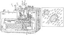
- FIG. 2is a perspective view of the laser microdissection instrument connected to a computer and display according to the invention
- FIG. 3is a perspective view of the laser microdissection instrument without the housing according to the invention.
- FIG. 4is a perspective view of the worksurface of the laser microdissection instrument according to the invention.
- FIG. 5is a front perspective view of the cutting laser components mounted on the frame of the laser microdissection instrument according to the invention.
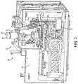
- FIG. 6is a rear perspective view of the fluorescence system mounted on the frame of the laser microdissection instrument according to the invention.
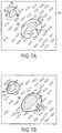
- FIG. 7Ais a top planar view of a biological sample with targeted portions encompassed by traces according to the invention.
- FIG. 7Bis a top planar view of a biological sample with targeted portions encompassed by cut paths according to the invention.
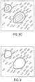
- FIG. 7Cis a top planar view of a biological sample with targeted portions encompassed by cut paths that are interspersed with bridges according to the invention.
- FIG. 8Ais a top planar view of a biological sample with capture laser shots located interior of the cut paths according to the invention.
- FIG. 8Bis a top planar view of a biological sample with capture laser shots located in between the bridges according to the invention.
- FIG. 8Cis a top planar view of a biological sample with an capture laser path that is curved across the interior of a cut path according to the invention.
- FIG. 9is a top planar view of a biological sample with targeted portions of biological material removed according to the invention.
- FIG. 10is a side elevation view of a transfer film carrier with targeted portions adhered thereto and separated from the remaining tissue sample according to the invention.
- FIG. 11is a top planar view of an image of a transfer film properly wetted by a capture laser according to the present invention.
- FIG. 12is a top planar view of an image of a calibration matrix of capture laser spots according to the present invention.
- a laser microdissection deviceoperates to carry out the following general steps.
- a tissue 10 or smear fixed on a standard microscope slide 12 by routine protocolsis introduced into a laser microdissection instrument.
- a polymer film or transfer film 14is provided which is typically affixed to a solid substrate forming a carrier 16 .
- the carrier 16can be of any shape.
- One shape for the carrieris a cap for conveniently introducing a sample into a vessel, such as a microcentrifuge tube, and sealing the vessel.
- the words “cap” and “carrier”are used interchangeably and it is understood by one skilled in the art that the carrier can be of any shape even where the term “cap” is employed.
- the tissue sample 10 mounted on a substrate surfaceis placed adjacent a transfer film carrier cap 16 which further ensures that transfer film 14 stays out of contact with the tissue 10 at this stage as shown in step one of FIG. 1 .
- the transfer film carrier 16can be placed in contact with the tissue 10 .
- a usermay select a region for microdissection.
- the selected section of the tissueis captured by pulsing at least one region of the transfer film with a low power infrared laser emitting a laser beam 18 which activates the transfer film 14 which then expands down into contact with the tissue 10 as shown in step two of FIG. 1 .
- the at least one activated region 20 of the transfer film 14adheres to the at least one identified portion of desired cell(s) 22 of the tissue sample.
- Microdissectionis completed by lifting the transfer film carrier 16 , with the desired cell(s) 22 attached to the transfer film 14 surface while the surrounding tissue remains intact as shown in step three of FIG. 1 .
- Extraction and subsequent molecular analysis of the cell contents, DNA, RNA or protein,are then carried out by employing devices and standard methods as shown in step four of FIG. 1 and described in U.S. application Ser. No. 09/844,187 entitled “Laser capture microdissection (LCM) extraction device and device carrier and method for LCM fluid processing” incorporated herein by reference in its entirety.
- LCDLaser capture microdissection
- Laser microdissectionemploys a polymer transfer film that is placed in juxtaposition to the tissue sample.
- the transfer filmmay or may not contact the tissue sample.
- This transfer filmis typically a thermoplastic manufactured containing organic dyes that are chosen to selectively absorb in the near infrared region of the spectrum overlapping the emission region of common AlGaAs infrared laser diodes.
- the exposed regionis heated by the laser and melts, adhering to the tissue in the region that was exposed.
- the filmis then lifted from the tissue and the selected portion of the tissue is removed with the film.
- Thermoplastic transfer filmssuch as a 100 micron thick ethyl vinyl acetate (EVA) film available from Electroseal Corporation of Pompton Lakes, N.J. (type E540) have been used in LCM applications.
- EVAethyl vinyl acetate
- the filmis chosen due to its low melting point of about 90° C.
- a laser microdissection instrument 24is shown connected to a computer 26 with a hard drive and an LCD monitor 27 .
- the computer 26includes the Windows operating system and basic Windows applications and is loaded with appropriate software to control instrument operation.
- the computerreceives input from the user and controls the operation of the laser microdissection instrument 24 .
- the laser microdissection instrument componentsare secured within a housing 28 that includes an automated sliding door 30 for accessing the instrument and inserting and removing tissue samples, slides and transfer film carriers.
- the laser microdissection instrument 24includes a microscope 32 mounted on an assembly frame 34 .
- the microscope 32includes an illumination system 36 , a worksurface 38 , a handling system 40 and an optical system 42 .
- the microscope frame 34carries the components of the microscope 32 .
- the illumination system 36comprises a white light illuminator 44 and a condenser 62 mounted on the frame 34 .
- the illumination system 36 , worksurface 38 and optical system 42are arranged in an inverted transmitted-light microscope fashion such that the illumination system is arranged above the worksurface 38 and at least one objective is arranged below the worksurface 38 .
- the worksurface 38is also mounted on the instrument frame 34 and is adapted for receiving one or more specimens and transmitting light therethrough.
- a vacuum chuckmay also be included to secure the specimen mounted on a specimen holder in position.
- the worksurface 38operates as a translation stage and is automatically or manually movable in all directions, in particular, the planar X-Y directions.
- the automated translation stageincludes a lateral translation motor and a fore-and-aft translation motor to allow complete manipulation in the X-Y plane.
- the motorsare controlled by a controller connected to the computer which receives input such as via a mouse cursor.
- a mouse cursorcan be used by an operator to trace a path on a visual display unit depicting a live or static image of the specimen to effect movement of the worksurface.
- a sophisticated road-map imaging system for navigating the specimenis described in U.S. Patent Publication No. 2002-0090122 which is incorporated herein by reference in its entirety.
- the worksurface 38includes slide locations 46 for handling multiple tissue samples simultaneously. Although three slide locations 46 are depicted, the invention is not so limited and any number of slide locations is within the scope of the present invention.
- Each slide location 46is designed to receive a substrate surface hearing sample tissue for microdissection.
- the substrate surface to be received within the slide locations 46is a standard microscope slide. Accordingly, the slide locations are appropriately dimensioned although the invention is not so limited and any type and style of substrate surface may be adapted to fit a customized worksurface.
- Each slide location 46includes at least one opening 48 in the worksurface 38 .
- the worksurface 38further includes a staging area 50 for receiving transfer film carriers 16 or cap cassettes.
- the worksurface 38also includes an unload station 52 for unloading caps from the slide locations 46 after microdissection.
- the unload station 52includes an unload slot 56 for receiving an unload tray onto which caps are placed.
- the worksurface 38also includes a quality control station 54 .
- the quality control station 54includes an opening (not shown) in the worksurface 38 that permits illumination and laser light to pass.
- the quality control station 54is designed for viewing the cap following cell capture, generating an image of the cap, and/or further ablating portions of the collected sample residing on the cap after cell capture.
- the handling system 40is connected to the frame 34 and comprises a lift fork 58 .
- the lift fork 58is moved in and out of the work surface by a translation motor and a lift motor operates to move the lift fork vertically.
- the lift forkis adapted to pick a carrier located at a staging or supply area of the worksurface and place the carrier in juxtaposition with the tissue specimen located in one of the slide locations 46 .
- the lift forkis adapted to pick the carrier from juxtaposition with the specimen and place it in the unload station 52 and/or quality control station 54 where the carrier may further cap an analysis vessel.
- the handling systemalso includes a visualizer filter.
- the visualizer filteris a piece of diffuser glass positioned above tissue sample.
- the light from aboveis diffused by the visualizer filter illuminating the sample from all angles.
- the visualizer filtercan be moved in and out of position and is located on the lift fork.
- the automated handling systemis described in detail in U.S. Pat. No. 6,690,470 to Baer et al. and is incorporated herein by reference in its entirety.
- the optical system 30 of the microscopeincludes several optical elements known to a person skilled in the art to make a microscope and laser microdissection instrument operate properly. These elements, mounted on the instrument frame, are combined to create an optical train of optical elements for pathing light.
- the optical systemincludes but is not limited to the following optical elements: mirror(s), dichroic mirror(s), lens(es), objective, beam-diameter adjuster, cut-off filter, diffuser, condenser, eyepiece and image acquisition system such as a camera.
- the optical system together with its optical elementsis arranged such that white light from the illumination system 36 passes down toward the worksurface 38 .
- the white lightpasses a dichroic mirror 60 and a focusing condenser lens 62 .
- the white lightpasses through one of the openings in the worksurface 38 along a primary optical axis and enters an objective 64 located beneath the worksurface 38 .
- Multiple objectivesare located on an objective turret wheel 66 which is automatically controlled by the computer.
- White light from the objective 64is then reflected by one or more mirrors 68 to an eyepiece (not shown) and/or a camera or image acquisition system 70 .
- the live image captured by the image acquisition system 70is transmitted to the computer and displayed on a visual display unit in a software application window for the live video.
- Static imagesmay also be captured by the image acquisition system and displayed side-by-side with the live video on the visual display unit in a software application window for the static roadmap image.
- a cut-off filtermay be located between the objective and the image acquisition system or eyepiece.
- a diffuser and a beam diameter adjuster(not shown) may also be incorporated in the optical train and located between the dichroic mirror and the translation stage.
- a series of microscope objectivesmay be selectably deployed from an objective turret wheel 66 which is controlled by an objective wheel motor while a second objective focus motor operates to automatically adjust the foci of objectives which have been positioned.
- the optical elementsmay be arranged in various ways for optimum performance.
- the capture laser source 72is typically an infrared (IR) laser source such as a AlGaAs laser diode having a wavelength of approximately 810 nanometers.
- the laser diode with collimating opticsemits a beam of IR laser light that is incident upon the dichroic mirror 60 .
- the capture or infrared laser beamenters the optical train at the dichroic mirror 60 and is reflected downward through the focusing condenser lens 62 and/or beam diameter adjuster toward the worksurface 38 .
- the dichroic mirror 60allows white light from the illumination system 36 to also pass toward worksurface resulting in the IR laser beam and the white light illumination being superimposed along the primary optical axis.
- a laser focus motorwhich is connected to the controller and computer operates to control the focusing lens 62 and adjust the IR laser beam spot size.
- the computer 26also delivers signals to the IR laser via the controller to initiate IR laser pulses, adjust beam size and control IR laser power.
- the capture laser 72operates in two modes, idle mode and pulse mode.
- idle modethe IR laser beam path provides a visible low amplitude signal that can be detected via the image acquisition system 70 when a visual alignment of the laser spot with a portion of tissue is desired.
- pulse modethe IR laser beam path delivers energy for microdissection and the optical characteristics of a cut-off filter attenuate the IR laser beam path sufficiently such that substantially none of the energy from the IR laser beam exits through the microscope.
- Suitable capture laser pulse widthsare from 0 to approximately 1 second, preferably from 0 to approximately 100 milliseconds, more preferably approximately 50 milliseconds.
- the spot size of the laser at the transfer filmis variable from approximately 1.0 to 100 microns, from 1 to 60 microns, or from 5 to 30 microns. From the standpoint of the clinical operator, the widest spot size range is the most versatile. A lower end point in the spot size range on the order of 5 microns is useful for transferring single cells.
- Suitable laserscan be selected from a wide power range. For example, a 100 milliwatt laser can be used. On the other hand, a 50 mW laser can be used. The laser can be connected to the rest of the optical subsystem with a fiber optical coupling. Smaller spot sizes are obtainable using diffraction limited laser diodes and/or single mode fiber optics. Single mode fiber allows a diffraction limited beam.
- the capture laser diodecan be run in a standard mode such as TEM 00 , other intensity profiles can be used for different types of applications.
- the beam diametercould be changed with a stepped lens (not shown) placed in the lens assembly. Changing the beam diameter permits the size of the portion of the transfer film that is activated to be adjusted. Given a tightly focused initial condition, the beam size can be increased by defocusing. Given a defocused initial condition, the beam size can be decreased by focusing. The change in focus can be in fixed amounts. Furthermore, the change in focus can be obtained by means of indents on a movable lens mounting and/or by means of optical glass steps.
- increasing or decreasing the optical path lengthis the effect that is needed to alter the focus of the beam, thereby altering the spot size.
- inserting a stepped glass prism into the beam so the beam strikes one step treadwill change the optical path length and alter the spot size.
- FIG. 5there is shown a front perspective view of a cutting laser source 74 in addition to related and interconnected cutting laser components such as a cutting laser power supply 76 and air channel 78 installed onto the frame 34 of the instrument 24 of FIG. 3 . While FIG. 3 does not show the cutting laser source 74 , it is to be understood that the cutting laser and its components are integrated into the instrument 24 of FIG. 3 in the manner shown in FIG. 5 and that FIG. 5 shows only the detail of the cutting laser components with other instrument components removed for clarity.
- a cutting laser source 74in addition to related and interconnected cutting laser components such as a cutting laser power supply 76 and air channel 78 installed onto the frame 34 of the instrument 24 of FIG. 3 . While FIG. 3 does not show the cutting laser source 74 , it is to be understood that the cutting laser and its components are integrated into the instrument 24 of FIG. 3 in the manner shown in FIG. 5 and that FIG. 5 shows only the detail of the cutting laser components with other instrument components removed for clarity.
- the cutting laser source 74is connected to the microscope and it is typically an ultraviolet (UV) laser source 74 .
- the UV laser sourceemits a beam of laser light that is reflected by one or more mirrors and directed into the primary optical axis.
- the UV laser lightenters the optical train and is reflected upward through the objective lens 64 .
- the objective 64focuses and adjusts the UV laser beam diameter.
- the UV laser beamthen travels toward the worksurface 38 and through one of the openings in the worksurface and at a tissue sample residing on a slide located in the slide location 46 or at a captured tissue sample located on a cap in the quality control station 54 .
- the worksurface 38is automatically moved to align particular openings in the worksurface with the optical paths of the lasers or primary optical axis for the intended operation.
- the dichroic mirror 60allows white light from the illumination system to also pass toward the worksurface 38 resulting in the UV laser beam and the white light illumination being superimposed along the primary optical axis.
- the UV lasercan be positioned above the worksurface 38 and directed through the focusing lens 62 along the primary axis and toward the specimen resting on the worksurface 38 .
- the computer 26also delivers signals to the cutting UV laser via the controller to initiate UV laser pulses, change beam diameter and control cutting UV laser power. UV laser pulse widths and beam diameter can be changed in the same manner as described above with respect to the IR laser source.
- FIG. 6a rear perspective view of a fluorescence system 80 connected to the frame 34 of the instrument 24 .
- FIG. 6displays the related and interconnected components of the fluorescence system 80 such as the power supply and light source 82 , EPI fluorescence illuminator 84 , filter wheel 86 and controller 88 installed onto the frame 34 of the instrument 24 of FIG. 3 . While FIG. 3 does not show the fluorescence system 80 , it is to be understood that the fluorescence system is integrated into the instrument 24 in the manner shown in FIG. 6 in addition to the components shown in FIG. 3 and optionally with the components of FIG. 5 and that FIG. 6 shows only the detail of the fluorescence system with other instrument components removed for clarity purposes only.
- the fluorescence system 80is adapted for automated selection of cells or specific regions of a sample for microdissection using fluorescently-stained tissue samples.
- image analysisthe fluorescently-labeled tissue is placed in a microdissection instrument and with the fluorescent system, the cells are detected through an analysis of the image formed by the microscope. Image analysis is known in the art and is also described in detail in WO 2004/025569 which is herein incorporated by reference in its entirety.
- the fluorescence system 80includes a fluorescence excitation light source, for example, a xenon or mercury lamp, which emits a specific wavelength or wavelength range.
- a fluorescence excitation light sourcefor example, a xenon or mercury lamp, which emits a specific wavelength or wavelength range.
- the specific wavelength or wavelength range of a beam emitted by the light sourceis selected by a fluorescence filter wheel 86 operated by a fluorescence filter changer motor, to excite a fluorescent system (chemical markers and optical filtering techniques that are known in the industry) that is incorporated in or applied to the sample to be microdissected.
- the wavelength range transmitted from the excitation light sourcecan be selected.
- the sampleincludes at least one member selected from the group consisting of chromophores and fluorescent dyes (synthetic or organic), and the process of operating the instrument includes identifying at least a portion of the sample with light that excites at least one member, before the step of transferring a portion of the sample to the laser microdissection transfer film.
- the fluorescent beamcan be made coincident or coaxial with both the IR/UV laser beam path and the white light from illuminator path. Fluorescence emitted by the sample is amplified by an objective changer 66 , reflected by a camera changer mirror and captured for live viewing by the acquisition system 70 which comprises a camera.
- a filter wheel 86 motoroperates to adjust the fluorescent beam and the emitted fluorescent beam.
- the objective changermay be implemented in the form of a wheel to accommodate a multiplicity of objectives (five objectives, as depicted) for providing different amplifications of the fluorescent image for the camera.
- objectivesfive objectives, as depicted
- a more detailed exposition of automated fluorescent laser microdissectionis found in U.S. Pat. No. 6,690,470 which is incorporated herein by reference in its entirety.
- a sample of biological material 10 to be microdissectedis applied to a substrate such as a glass slide 12 using routine protocols.
- the substrate with the sample affixed theretois inserted into the laser microdissection instrument 24 through automatic door 30 and inserted into a slide opening 48 located on the worksurface 38 .
- the instrument 24automatically detects the presence of a slide 12 when a slide is inserted into a slide opening 48 located on the worksurface 38 .
- This automatic slide detectioncan be accomplished in many ways known to one skilled in the art. For example, when a slide is inserted into a slide opening 48 , a camera 70 or other sensor included in the instrument 24 calculates a brightness differential indicative of the presence of a slide and an appropriate signal is registered with the user.
- the camera 70 or other sensorWhen the slide opening 48 is empty, the camera 70 or other sensor reads a first brightness level of the illumination light. When a slide is inserted into a slide opening 48 , the camera image sensor or other sensor calculates a second brightness reading wherein the second brightness reading is lower than the first brightness reading and thereby, indicating that a slide has been inserted. Alternatively, when a slide is inserted into a slide opening 48 on the worksurface 38 , a light path is blocked by a spring-set flange or by the slide itself indicating the presence or absence of a slide. Upon automatic detection of the slide 12 in the slide opening 48 , the camera 70 automatically records a static image of the slide to create a roadmap image and displays it on the visual display unit connected to the computer in a software application window for the static roadmap image.
- the handling system 40is used to bring a carrier 16 with a transfer film 14 affixed to its surface from the cap staging area 50 to the slide location 46 and in juxtaposition to the sample.
- a software interface window displayed on the visual display unitdepicts the worksurface graphic and movement of caps is effected by moving an input device such as a mouse, clicking on a cap and dragging it onto the graphic slide location desired and releasing the mouse button.
- Software and controllersengage the handling system to effect movement accordingly.
- the worksurface 38is automatically moved into the primary optical axis such that a selected opening associated with a slide location 46 or quality control station 54 in the worksurface is aligned with the optical axis and ready for microdissection.
- the carrier 16is placed in contact with the sample such that the transfer film contacts the biological material substantially across the entirety of the transfer film surface.
- the carrier 16is formed with standoffs 90 such that a substantial portion of the transfer film 14 does not contact the biological material 10 but remains spaced a distance from the sample 10 as shown in step one of FIG. 1 .
- Standoffsare described in U.S. patent application Ser. No. 08/984,979 which is herein incorporated by reference in its entirety. Standoffs are structural features that protrude from the surface of the carrier on the side of the transfer film to provide a spacing between the transfer film and the sample in order to avoid transfer of unwanted friable biological material that would otherwise adhere to the transfer film due to electrostatic forces and the like.
- the illumination system 36is activated shedding light on the sample 10 .
- the white light penetrating the samplearrives at the objective 64 and is directed to the acquisition system 70 and/or eyepiece.
- a live image that is captured by the acquisition system 70is displayed on the computer monitor 27 .
- a static image of relatively lower magnificationis captured so as to provide a roadmap image for navigating the sample space.
- the two imagesare displayed side-by-side to locate the user on the sample space map and simultaneously provide a display of the local sample space having a relatively larger magnification.
- the operatorinspects the sample by moving the translation stage via computer inputs, controllers and appropriate software. For example, navigation of the sample space is accomplished by tracing a path on the displayed monitor image using an input cursor via a mouse, joystick or other input means.
- a targeted portion 92 of biological material 94is identified either manually by the operator or automatically employing software for algorithmic identification of regions of interest.
- fluorescent systemsare employed for assisting the automated identification of targeted portions of biological material.
- the usercan trace a targeted portion 92 of biological material viewed on the display monitor by moving a mouse cursor.
- Each trace 96defines an interior 98 and an exterior 100 .
- the interior 98includes the targeted portion(s) and the exterior 100 of the trace includes non-targeted biological material.
- One or more targeted portions of biological materialcan be traced and the trace can be of any shape and size as shown in FIG. 7 a .
- Various software microdissection tools for selecting targeted portions of biological materialare available.
- microdissection toolsfor indicating which cells the capture laser or cutting laser will capture or ablate, respectively, and operate the tools on the live or static image displayed on the computer monitor.
- Microdissection toolsinclude single point dissection for targeting cells individually, line dissection for drawing a line on the image to target a layer or line of cells, free form dissection for identifying an area to be targeted, and exclusion dissection for deselecting a specific area from targeting.
- the instrumentis optionally selecting for capture only with the capture laser as described with respect to FIG. 1 or ablation with the cutting laser combined with capture with capture laser in a process known as “cut-and-capture”.
- the tracedefines a cut line for the cutting laser source.
- the useris prompted by the computer to commence cutting the traces with the cutting laser source 74 .
- the usermay select whether each of the traces are to be closed or substantially closed paths for the cutting laser 74 . If the user selects closed paths, the cutting laser source is automatically directed and activated to cut along the traces at a predefined cut width 102 forming a cut path 101 as shown in FIG. 7 b . If the user selects a substantially closed path, at least one bridge 104 spanning from the interior 98 to the exterior 100 will be formed such that the interior 98 is joined to the surrounding exterior 100 biological material at the location of the bridge 104 as shown in FIG.
- the cut path 101is interspersed with bridges 104 formed when the UV cutting laser beam is temporarily de-activated while moving along a trace.
- the bridge width 108can be selected by the user or predetermined by controlling software.
- Bridge locationsmay be user-defined by clicking with the mouse cursor along the trace at locations where bridges are desired as shown by the “x” in FIG. 7 a . The user thereby manually selects any number and location of the bridges. Alternatively, the computer may automatically form a predefined number of bridges.
- the UV laseris activated and the biological material is eroded along the cut path but at bridge locations, biological material remains intact.
- the cut line control unitcomprises a laser scanning device which moves the laser beam relative to the stationary sample during cutting.
- the worksurface 38 with the sampleis not displaced during cutting but remains fixed in the optical axis.
- the cut lineresults exclusively from deflection of the laser beam over the sample.
- the capture laser 72is directed at the one or more interiors 98 of the trace paths 96 .
- the IR capture laser 72is fired or pulsed at an interior 98 to activate the transfer film layer in the location of the interior which then adheres to the interior portion of the biological material. If a carrier with standoffs is being employed, the activated transfer film bridges the distance of the standoffs 90 to contact and adhere to the interior of biological material.
- An IR laser pulse showing a location of adhesion to the interior of biological materialis shown as a circle 106 in FIG. 8 a.
- the IR capture laser 72can be fired once to create a single area of adhesion or the IR laser can be fired more than once to create more than one area of adhesion on any one interior portion of biological material.
- the single IR laser shotcan be directed in the center of the interior.
- the IR laser shotcan be directed at the interior of the trace but at a portion of the interior that was not targeted as desirable biological material as shown in FIG. 8 a .
- the IR lasercan be strategically directed at such a location to advantageously avoid raising the temperature of desired biological material in the area of the IR laser shot which would result from localized heating.
- IR laser shots shown as circles 106 on FIG. 8 bcan be directed in-between the bridge locations so that such points of adhesion would assist in the breaking of the bridges when the carrier is lifted away. Also, the IR laser shots can be directed at or in the proximity of the bridge locations.
- a usercan, for example, click with a mouse cursor at a location where the user desires an IR laser shot to be located. Also, the user may select the number of IR laser shots that are to be made by clicking with a mouse cursor more than once.
- IR laser shotsare delivered automatically
- computer softwareis programmed by the user beforehand or determined automatically to carry out one or more IR laser shots in a uniform or non-uniform pattern of IR laser shots across the interior of a trace.
- a single IR laser shot as well as a strategically placed IR laser shotcan also be carried out automatically by the computer.
- the IR laser shotis not limited to being a single pulse to create a single point of adhesion.
- the IR lasercan be fired with multiplicity or at duration to trace an IR path 110 of adhesion of any shape within the interior as shown in FIG. 8 e .
- the IR laser path of adhesionis carried out in the same manner as the UV laser path of cutting. Either the worksurface 38 is moved to create a path or the IR laser beam is directed across the interior with the worksurface remaining stationary.
- the number of IR laser shots, the shape of the IR laser shots and their locationare not limited and any number, pattern, location or shape of IR laser shots is within the scope of the invention.
- the IR laser shot or shotscan be fired before the UV laser is activated to cut the biological material.
- the carrier with the transfer filmwill result in one or more areas of adhesion located in the one or more interiors of the cutting laser 74 cut paths.
- the carrierWhen the carrier is removed by lifting it vertically, the carrier with its attached transfer film and at least one adhered targeted portion of biological material is separated from the remaining layer of biological material. If bridges were formed, those bridges are mechanically broken upon lifting the carrier to free the adhered portions of targeted biological material. What remains is un-targeted biological material as shown in FIGS. 9 and 10 . Being adhered to the transfer film, the targeted biological material is removed with the carrier and available for further processing.
- the capture laser 74 shotsare delivered automatically and the automatically locate capture laser option is selected in the software, appropriate computer software is programmed to automatically detect the position of the capture laser 74 prior to its activation. Because the capture laser beam can be located anywhere within a predetermined area, it is advantageous to automatically determine the position of the capture laser to provide starting coordinates from which the capture laser beam can be accurately directed to the capture locations. In older instruments, the capture laser is located manually by the user. To manually locate the laser beam, the user moves the worksurface 38 so that a clear laser beam spot appears in the center of the live video window.
- the userplaces the point of the cursor of the computer mouse for example, directly on the center of the laser beam spot and then indicates to the computer that the laser beam has been located by right-clicking on the mouse button and selecting that the location of the laser has been selected.
- automatically locating the capture laser beamestablishes a connection between the cursor and the laser beam so that when the user clicks to fire or target the capture laser, the laser accurately fires on the cells that the user selected.
- the instrument 24automatically locates the capture laser beam without requiring any user intervention. Automatic detection of the capture laser beam is accomplished with appropriate computer software and controllers directing the system to locate the capture laser.
- the background illuminationsuch as the white light illuminator 44 is automatically turned off. This step is useful in situations where the capture laser targeting beam is too weak to be seen by the user such as when the capture laser beam is operating in idle mode or if the laser beam intensity is on a low setting. Therefore, it is useful to turn off the background illumination or alternatively, increase the laser beam intensity.
- the laseris set at a level sufficient to be detected by the digital image sensor. This level is generally selected to be below the power level that melts the polymer film.
- the laser beam spotis detected by the camera as a bright spot relative to the neighboring areas.
- the exact location of the bright spot and laser beam locationis calculated from brightness levels detected by the digital camera image sensor of the acquisition system 70 . Given a particular magnification, the pixel coordinates of the beam spot location are translated to planar coordinates for establishing a zeroed location from which the worksurface or the laser beam is precisely directed to areas of interest.
- the intensity of the capture laseris increased or fired so that a bright spot is more easily detected.
- the transfer filmis not activated when the laser is fired to locate the beam because the light intensity is set to a low level.
- the background illumination lightis turned back on if it was previously turned off.
- the same procedure described abovemay be performed for locating the position of the cutting laser. If the cutting laser is activated to indicate a bright spot, it is first directed away from tissue or other desired or sensitive locations to avoid ablation of wanted tissue.
- the laser microdissection instrument of the present inventionincludes an automatic focus feature that automatically focuses the image on the tissue sample being displayed in the live video window. Focusing the tissue sample that is displayed in the live video window involves moving the objective lens 64 in and out until the sharpest possible image of the subject is achieved. Depending on the distance of the subject from the camera, the objective has to be a certain distance from the object tissue to obtain a clear image.
- the instrumentmay employ active or passive autofocus techniques that well known in the art.
- an autofocus sensorsuch as a charge-coupled device (CCD) is included which provides input to algorithms and a microprocessor determines the optimum focus distance for the objective. The instrument automatically focuses on the tissue when a slide is inserted into a slide location and placed in view of the acquisition system.
- CCDcharge-coupled device
- the laser microdissection instrument of the present inventionfurther includes an automatic focus lock for the capture laser beam that advantageously keeps the capture laser beam focused even after the objective lens is changed or the tissue being observed is varied.
- the capture laser beamis first focused automatically or manually by moving the beam to an area where there is no tissue or the tissue is very thin and light.
- the capture laser beamis activated and the coarse and fine focus settings are selected on the software program interface and adjusted until the capture laser beam is a discrete point as viewed in the live image display window.
- the coarse and fine focus settingsoperate to control the laser focus motor.
- the laser focus motoris connected to the controller and computer and operates to control the focusing lens 62 and adjust the capture laser beam focus.
- the capture laser focus settingis recorded as the distance of the laser focusing lens 62 to the focal plane and serves as a baseline from which the focusing lens 62 will be moved to keep the capture laser beam in focus.
- Both the objective lens and focusing lensfocus on the focal plane of the tissue being observed.
- the imageis automatically or manually re-focused by automatically or manually moving the objective lens up or down by an objective distance. This objective distance is recorded. If the newly focused region is a region desired for capture, the instrument will prepare for capture by automatically moving the capture laser focusing lens 62 a distance from the focal plane equal to the objective distance that the objective was moved to bring the image into focus in order to keep the capture laser beam set at the desired focus.
- the step of automatically keeping the capture laser beam at the desired focusincludes moving the laser focusing lens away from the worksurface and if the objective lens is moved away from the worksurface on re-focus, the step of automatically keeping the first laser source at the desired focus includes moving the laser focusing lens toward the worksurface.
- the computerdrives the appropriate motors to turn the objective turret wheel such that the desired objective is positioned in the primary axis.
- the autofocus systemthen immediately focuses the image based on the newly selected objective by activating the objective focus motor to move the objective up or down a distance to automatically adjust the foci of the objective which has been positioned and focus the image.
- the focusing lensis kept locked after the new objective is initially focused. This distance that the objective moves to adjust for the newly positioned objective is not recorded and summed together with the other objective distances. However, for any subsequent objective distances that the objective is moved, the focusing lens is moved accordingly, the objective distances being recorded and summed in one variation.
- the capture laseris automatically focused such that the focal plane of the capture laser matches the focal plane of the objective lens. If the objective lens is changed, it needs to be refocused. After it is refocused, the focal plane of the capture laser is matched to the focal plane of the new objective.
- the cutting laser beam focusis automatically maintained each time the image is focused. If the instrument is arranged such that the cutting laser and the capture laser locations are reversed such that the cutting laser is located above the worksurface and the capture laser is located under the worksurface and the cutting laser is focused by the focusing lens 62 and the capture laser is focused by the objective 64 , an automatic focus lock for the cutting laser beam is provided in the same manner as that described above for the capture laser automatic focus lock. It should be noted that in one variation, both the cutting laser and the capture laser are located on the same side of the worksurface and are both focused by the objective lens. In another variation, both the cutting laser and capture laser are located on the same side of the worksurface and are both focused by the focusing lens in accordance with the method described above for the capture laser automatic focus lock.
- wettingrefers to the melting of the transfer film on the polymer cap so that it fuses adequately to the tissue or cells when the capture laser fires.
- the transfer filmis visible as a dark ring 120 fused to the slide and the center 122 of the ring is clear, the wetting is adequate as shown in FIG. 11 . If the wetting is not adequate, one or more capture laser parameters such as power and duration are adjusted.
- the power setting of the capture laseris increased if the wetting is not adequate.
- the duration of the capture laseris increased.
- the capture laser beamis directed at an adjacent location and test fired again at the higher power and/or duration setting. The area is observed to determine whether wetting is adequate. If not, the process is repeated with the power setting or duration being increased incrementally. Determination of whether wetting is adequate may be accomplished manually by the user via observation or automatically by the instrument employing various algorithms.
- the acquisition system camera image sensorrecords intensity data for an image of each test fire location. The microprocessor looks at the difference in intensity among the adjacent pixels and detects a maximum intensity difference between adjacent pixels that correspond to a dark ring to determine the optimum energy setting.
- a calibration matrixis used to determine capture laser settings.
- the laser matrix optionallows the user to set up a test firing pattern to determine the appropriate settings for the capture laser to adequately wet the film.
- the userFor one axis of the matrix, the user enters the number of steps for power increments, the power increment per step, and the distance between laser spots.
- the userFor another axis of the matrix, the user enters the number of steps for duration increments, the duration increment per step, and the distance between laser spots.
- the computerautomatically fires the capture laser test pattern according to the settings to create a matrix as shown in FIG. 12 . The user then observes the pattern and selects the optimum power and duration settings for the capture laser as desired.
- the cutting laseris fired at an area of tissue and the area is examined for a proper tissue burn spot.
- a tissue burn spottypically appears white in color. If there is no burn spot detected on the tissue, one or more cutting laser parameters such as power and duration are adjusted.
- the power setting of the cutting laseris increased if the burn is not adequate.
- the duration of the cutting laseris increased.
- the cutting laser beamis directed at an adjacent location and test fired again at the higher power and/or duration setting. The area is observed to determine whether burn sport is adequate. If not, the process is repeated with the power setting or duration being increased incrementally. Determination of whether the burn spot is adequate is typically accomplished manually by the user via observation.
- a calibration matrixis used to determine cutting laser settings as described above with respect to the capture laser calibration matrix and FIG. 12 .
- the laser matrix optionallows the user to set up a test firing pattern to determine the appropriate settings for the cutting laser to adequately cut the film. For one axis of the matrix, the user enters the number of steps for power increments, the power increment per step, and the distance between laser spots. For another axis of the matrix, the user enters the number of steps for duration increments, the duration increment per step, and the distance between cutting laser spots.
- the computerautomatically fires the cutting laser test pattern according to the settings to create a matrix similar to that shown in FIG. 12 for the capture laser. The user then observes the pattern and selects the optimum power and duration settings for the cutting laser as desired.
- the instrumentincludes a worksurface 38 that includes at least one cap quality control station 54 .
- the quality control station 54is one or more than one location on the worksurface designed for viewing the captured tissue after microdissection.
- the worksurface 38 at the location of the quality control stationincludes an opening such that when a cap is placed in the quality control station, illumination or laser light passes through the opening and through the cap.
- the captured tissue adhered to the transfer film on the capis illuminated for observation or exposed to the capture laser or cutting laser for ablation.
- capture in the slide location 46is by any one or more of the methods described in U.S. Provisional Patent Application Ser. No. 60/613,038, entitled “Automated microdissection instrument” filed on Sep. 25, 2004; U.S. patent application Ser. No. 10/989,206 entitled “Automated laser capture microdissection” filed on Nov. 15, 2004; U.S. patent application Ser. No. 11/222,281 entitled “Laser microdissection apparatus and method” filed on Sep. 8, 2005; and U.S. patent application Ser. No.
- the sampleundergoes laser capture microdissection with a capture laser while in the slide location prior to being placed in the quality control station where it is further observed and exposed to the cutting laser and/or capture laser.
- the sampleundergoes microdissection with a cutting laser and is exposed to the capture laser prior to being placed in the quality control station where it is further observed and exposed to the cutting laser and/or capture laser.
- the userinspects the slide and the cap in the quality control station to verify that collection was successful.
- the cameracaptures a static or live image of the cap transfer surface including the accompanying captured tissue and displays it on the computer monitor. The image is displayed either on the live video window or the static image window of the computer software interface, and the user inspects the quality of the capture. If there is undesirable friable tissue or other matter still attached or capture is incomplete or unsatisfactory, undesirable portions of the tissue can be targeted for ablation with the cutting laser while the cap is located in the quality control station and/or targeted for laser capture with the capture laser while the cap is located in the quality control station.
- Photoablationthe volitization of tissue by light emitted from an ultraviolet cutting laser, while the cap is in the quality control station is performed interactively.
- the userablates any unwanted tissue from the material on the cap.
- In the second modeuser holds one or more hot keys such as the CONTROL and SHIFT keys at the same time and moves the mouse cursor to move the laser.
- the cutting laserfires only while the keys are depressed and when released, the laser turns off.
- inspection and microdissectionis completed in the quality control station, the user points the mouse cursor on the cap depicted on the software interface residing in the quality control station and directs the cursor to move the cap from the quality control station to the unload station 52 .
- a new capwhen introduced into the laser microdissection instrument, is located in the staging area 50 of the worksurface 38 .
- the capis placed on a slide located in any one or more slide locations 46 on the worksurface.
- the capmay be moved to the quality control station or directly to a particular location on the unload station 52 .
- the capis disassociated from its identifying slide and tissue information. It is desirable to identify which slide or tissue sample a cap or microdissected region is associated with or from. To accomplish this identification, each cap is tracked by recording one or more tracking information and associating that tracking information with each cap.
- a tracking informationis any useful identification information that is associated with a particular cap.
- the tracking informationmay include a cap number, cap style, project number, or any other information.
- An example of a cap number or identificationis the cap's location in the cap station. For example, if the cap is first in the cap station it may be assigned a tracking information of “CAP #1”. Additional information or notes may be associated with this identification including date and time of microdissection for example, and the style of cap that is used such as the CapSureTMHS or CapSureTM Macro.
- SLIDE #3to identify the tissue-bearing slide in a slide opening 48 on the slide location 46 on which the cap was placed.
- “SLIDE #3”for example designates the third slide opening 48 in the slide location 46 .
- Additional information associated with a particular slide that has been entered by the user or automatically recordedsuch as the slide name, tissue type, number of captures, total area of captures and special notes and type of slide or any other useful or important information that is associated with “SLIDE #3” is also recorded with the other previously-recorded tracking informations. From the slide station, the cap may be moved to the quality control station 54 and an additional tracking information such as “QC” may be recorded and associated with the cap.
- the capis moved into the unload station 52 and positioned in a particular location on the unload station and another tracking information, such as the coordinates of the cap location on the unload station, “X1,Y1”, is recorded and associated with the cap.
- another tracking informationsuch as the coordinates of the cap location on the unload station, “X1,Y1”
- a tracking informationis assigned, recorded and associated with the cap.
- a tracking reportmay include a string of tracking codes such as “CAP #1” “SLIDE #3” “EPITHELIAL” “QC” “X1,Y1”. Such a tracking report informs the user that the captures on CAP #1 came from tissue sample on SLIDE #3.
- Additional tracking informationthat may be associated with a particular cap include a roadmap image of the slide from which tissue was captured, an information associated with a reading of a barcode located on the slide from which tissue was captured or a picture of the barcode itself.
- the tracking informationis recorded and associated with the first substrate or cap linking the first substrate or cap, the biological material, and the at least one second substrate or tissue slide(s) from which the biological material was removed. It should be noted that a single cap can be used to collect material from more than one slide.
- Alternative methods of tracking information associated with a capinclude burning a tracking code or other identified with a laser such as the UV cutting laser onto the cap itself or onto the transfer film with the IR capture laser in dot matrix format for example to script the information.
- Another methodincludes simply associating the static roadmap image of at least a portion of the slide with the particular cap such that the tracking information outputs the associated roadmap image.
- Yet another methodincludes, reading a slide label information such as a barcode, alpha-numeric text or other characters, and recording the slide label information associated with the cap.
- the slide label informationis converted and the converted data is associated with the cap. For example, a bar code is read and converted into text data for example and the text data is recorded and associated with the cap.
- Another exampleincludes optical character recognition of characters on the slide which is then reproduced, recorded and associated with a cap.
- a camera of the acquisition systemcan be used to capture slide information and the image itself can be associated with the cap or data can be deciphered from the image in another variation.
Landscapes
- Physics & Mathematics (AREA)
- General Physics & Mathematics (AREA)
- Health & Medical Sciences (AREA)
- Life Sciences & Earth Sciences (AREA)
- Chemical & Material Sciences (AREA)
- Analytical Chemistry (AREA)
- Biochemistry (AREA)
- General Health & Medical Sciences (AREA)
- Immunology (AREA)
- Pathology (AREA)
- Sampling And Sample Adjustment (AREA)
Abstract
Description
Claims (10)
Priority Applications (4)
| Application Number | Priority Date | Filing Date | Title |
|---|---|---|---|
| US16/208,557US10605706B2 (en) | 2004-09-25 | 2018-12-03 | Automated microdissection instrument with controlled focusing during movement of a laser beam across a tissue sample |
| US16/790,595US11175203B2 (en) | 2004-09-25 | 2020-02-13 | Automated microdissection instrument using tracking information |
| US17/516,605US11703428B2 (en) | 2004-09-25 | 2021-11-01 | Automated microdissection instrument and method for processing a biological sample |
| US18/336,855US12372440B2 (en) | 2004-09-25 | 2023-06-16 | Automated microdissection instrument and method for processing a biological sample |
Applications Claiming Priority (6)
| Application Number | Priority Date | Filing Date | Title |
|---|---|---|---|
| US61303804P | 2004-09-25 | 2004-09-25 | |
| US66443805P | 2005-03-23 | 2005-03-23 | |
| US11/236,045US8722357B2 (en) | 2001-11-05 | 2005-09-26 | Automated microdissection instrument |
| US14/275,812US20140335560A1 (en) | 2001-11-05 | 2014-05-12 | Automated Microdissection Instrument |
| US15/434,200US10156501B2 (en) | 2001-11-05 | 2017-02-16 | Automated microdissection instrument for determining a location of a laser beam projection on a worksurface area |
| US16/208,557US10605706B2 (en) | 2004-09-25 | 2018-12-03 | Automated microdissection instrument with controlled focusing during movement of a laser beam across a tissue sample |
Related Parent Applications (1)
| Application Number | Title | Priority Date | Filing Date |
|---|---|---|---|
| US15/434,200DivisionUS10156501B2 (en) | 2001-11-05 | 2017-02-16 | Automated microdissection instrument for determining a location of a laser beam projection on a worksurface area |
Related Child Applications (1)
| Application Number | Title | Priority Date | Filing Date |
|---|---|---|---|
| US16/790,595DivisionUS11175203B2 (en) | 2004-09-25 | 2020-02-13 | Automated microdissection instrument using tracking information |
Publications (2)
| Publication Number | Publication Date |
|---|---|
| US20190120734A1 US20190120734A1 (en) | 2019-04-25 |
| US10605706B2true US10605706B2 (en) | 2020-03-31 |
Family
ID=66169228
Family Applications (5)
| Application Number | Title | Priority Date | Filing Date |
|---|---|---|---|
| US15/434,200Expired - LifetimeUS10156501B2 (en) | 2001-11-05 | 2017-02-16 | Automated microdissection instrument for determining a location of a laser beam projection on a worksurface area |
| US16/208,557Expired - LifetimeUS10605706B2 (en) | 2004-09-25 | 2018-12-03 | Automated microdissection instrument with controlled focusing during movement of a laser beam across a tissue sample |
| US16/790,595Expired - LifetimeUS11175203B2 (en) | 2004-09-25 | 2020-02-13 | Automated microdissection instrument using tracking information |
| US17/516,605Expired - LifetimeUS11703428B2 (en) | 2004-09-25 | 2021-11-01 | Automated microdissection instrument and method for processing a biological sample |
| US18/336,855Expired - LifetimeUS12372440B2 (en) | 2004-09-25 | 2023-06-16 | Automated microdissection instrument and method for processing a biological sample |
Family Applications Before (1)
| Application Number | Title | Priority Date | Filing Date |
|---|---|---|---|
| US15/434,200Expired - LifetimeUS10156501B2 (en) | 2001-11-05 | 2017-02-16 | Automated microdissection instrument for determining a location of a laser beam projection on a worksurface area |
Family Applications After (3)
| Application Number | Title | Priority Date | Filing Date |
|---|---|---|---|
| US16/790,595Expired - LifetimeUS11175203B2 (en) | 2004-09-25 | 2020-02-13 | Automated microdissection instrument using tracking information |
| US17/516,605Expired - LifetimeUS11703428B2 (en) | 2004-09-25 | 2021-11-01 | Automated microdissection instrument and method for processing a biological sample |
| US18/336,855Expired - LifetimeUS12372440B2 (en) | 2004-09-25 | 2023-06-16 | Automated microdissection instrument and method for processing a biological sample |
Country Status (1)
| Country | Link |
|---|---|
| US (5) | US10156501B2 (en) |
Families Citing this family (6)
| Publication number | Priority date | Publication date | Assignee | Title |
|---|---|---|---|---|
| US10156501B2 (en) | 2001-11-05 | 2018-12-18 | Life Technologies Corporation | Automated microdissection instrument for determining a location of a laser beam projection on a worksurface area |
| CN107209091A (en)* | 2015-01-31 | 2017-09-26 | 豪夫迈·罗氏有限公司 | Systems and methods for intermediate dissection |
| CN110187353A (en)* | 2019-05-22 | 2019-08-30 | 北京石油化工学院 | A long-range target laser ranging method |
| CN111366435A (en)* | 2020-04-27 | 2020-07-03 | 中国科学院广州生物医药与健康研究院 | A kind of biological sample laser cutting automatic separation device and separation method |
| EP4303637A1 (en)* | 2022-07-04 | 2024-01-10 | Leica Microsystems CMS GmbH | Sample manipulation device and method |
| CN115308004B (en)* | 2022-10-12 | 2022-12-23 | 天津云检医学检验所有限公司 | Laser capture microdissection method |
Citations (202)
| Publication number | Priority date | Publication date | Assignee | Title |
|---|---|---|---|---|
| DE1263339B (en) | 1963-06-04 | 1968-03-14 | Reichert Optische Werke Ag | Microscope suitable for reflected and / or transmitted light examinations with two light sources |
| US3680947A (en) | 1970-04-21 | 1972-08-01 | Western Electric Co | Microscope apparatus with movable fluid bearing object support |
| US3705769A (en) | 1970-11-12 | 1972-12-12 | Johannsmeier Karl Heinz | Optical alignment and contact printing system with improved chuck assembly |
| US3848962A (en) | 1973-10-18 | 1974-11-19 | Coulter Electronics | Slide mounting apparatus for microscopy |
| CH566015A5 (en) | 1973-04-12 | 1975-08-29 | Ciba Geigy Ag | Producing relief contrast in microscope image of phase object - including suppression of disturbing interference and refraction |
| US4210384A (en) | 1976-09-11 | 1980-07-01 | Carl Zeiss-Stiftung | Inverted-design optical microscope |
| US4303866A (en) | 1979-06-12 | 1981-12-01 | Costruzioni Aeronautiche Giovanni Agusta S.P.A. | Method and device for mounting pieces inside the vacuum chamber of an electron microscope |
| US4333983A (en) | 1980-04-25 | 1982-06-08 | Optical Coating Laboratory, Inc. | Optical article and method |
| US4436385A (en) | 1980-07-25 | 1984-03-13 | Carl-Zeiss-Stiftung | Specimen holder for inverted microscopes |
| US4508435A (en) | 1982-06-18 | 1985-04-02 | Coulter Electronics, Inc. | Air vacuum chuck for a microscope |
| US4509834A (en) | 1982-03-24 | 1985-04-09 | Hodgson R W | Positioning apparatus for positioning a workpiece relative to a frame of reference |
| US4538885A (en) | 1982-06-18 | 1985-09-03 | Coulter Electronics, Inc. | Optical microscope system |
| US4552033A (en) | 1980-07-08 | 1985-11-12 | Gebr. Marzhauser Wetzlar oHG | Drive system for a microscope stage or the like |
| US4600282A (en) | 1983-11-14 | 1986-07-15 | Canon Kabushiki Kaisha | Alignment apparatus |
| US4614431A (en) | 1983-02-18 | 1986-09-30 | Hitachi, Ltd. | Alignment apparatus with optical length-varying optical system |
| US4623839A (en) | 1982-09-17 | 1986-11-18 | Angliatech Limited | Probe device for testing an integrated circuit |
| US4627009A (en) | 1983-05-24 | 1986-12-02 | Nanometrics Inc. | Microscope stage assembly and control system |
| US4661692A (en)* | 1983-03-29 | 1987-04-28 | Olympus Optical Co., Ltd. | Microscope provided with automatic focusing device having memory means |
| US4672559A (en) | 1984-12-26 | 1987-06-09 | E. I. Du Pont De Nemours And Company | Method for operating a microscopical mapping system |
| US4673261A (en) | 1985-05-16 | 1987-06-16 | Alessi Industries, Inc. | Motion control apparatus for precise repeatable positioning |
| US4684781A (en) | 1985-01-29 | 1987-08-04 | Physical Sciences, Inc. | Method for bonding using laser induced heat and pressure |
| US4702565A (en) | 1985-03-07 | 1987-10-27 | Carl-Zeiss-Stiftung | Cross-slide stage for a microscope |
| US4731530A (en) | 1986-04-21 | 1988-03-15 | Mikan Peter J | Joystick control having optical sensors |
| US4760385A (en) | 1985-04-22 | 1988-07-26 | E. I. Du Pont De Nemours And Company | Electronic mosaic imaging process |
| US4807984A (en) | 1986-02-18 | 1989-02-28 | Hitachi, Ltd. | Apparatus and method for specimen inspection |
| US4824229A (en) | 1986-04-09 | 1989-04-25 | Sapporo Breweries, Ltd. | Microscope with automatic sweeping device |
| US4836667A (en) | 1986-05-06 | 1989-06-06 | Slidex Corporation | Microscope |
| US4852985A (en) | 1986-10-16 | 1989-08-01 | Olympus Optical Co., Ltd. | Illuminating device for microscopes |
| US4856873A (en) | 1987-05-15 | 1989-08-15 | Storz Instrument Company | Documentation illumination module |
| US4871245A (en) | 1986-10-27 | 1989-10-03 | Olympus Optical Co., Ltd. | Surgical microscope |
| US4920053A (en) | 1984-03-29 | 1990-04-24 | Olympus Optical Co., Ltd. | Method for micromanipulating cells by moving cell-containing vessel on stage of inverted microscope while pricking cells with tip of stylus |
| US4923294A (en) | 1988-10-20 | 1990-05-08 | Micron Technology, Inc. | Lead frame holding device |
| US4954715A (en) | 1989-06-26 | 1990-09-04 | Zoeld Tibor | Method and apparatus for an optimized multiparameter flow-through particle and cell analyzer |
| US4964708A (en) | 1989-07-14 | 1990-10-23 | Mason Michael S | Microscope for medical surgery |
| US4987006A (en) | 1990-03-26 | 1991-01-22 | Amp Incorporated | Laser transfer deposition |
| WO1991000768A1 (en) | 1989-07-06 | 1991-01-24 | A. Ahlstrom Corporation | Method and apparatus for treating fiber suspension |
| US4992660A (en) | 1989-06-26 | 1991-02-12 | Jeol Ltd. | Scanning tunneling microscope |
| US5017428A (en) | 1987-02-07 | 1991-05-21 | Pelikan Aktiengesellschaft | Multiple impression thermal transfer ribbon |
| US5029791A (en) | 1990-03-08 | 1991-07-09 | Candela Laser Corporation | Optics X-Y positioner |
| US5037207A (en) | 1986-02-12 | 1991-08-06 | Ohio State University Research Foundation | Laser imaging system |
| US5057689A (en) | 1989-09-20 | 1991-10-15 | Matsushita Electric Industrial Co., Ltd. | Scanning electron microscope and a method of displaying cross sectional profiles using the same |
| US5077620A (en) | 1990-06-06 | 1991-12-31 | George Mauro | Motorized optical component positioning stage |
| US5089909A (en) | 1987-05-15 | 1992-02-18 | Storz Instrument Company | Documentation illumination module for a microscope system |
| US5103338A (en) | 1990-10-04 | 1992-04-07 | Crowley Kevin D | Apparatus for positioning objects for microscopic examination |
| US5126877A (en) | 1990-09-08 | 1992-06-30 | Carl-Zeiss-Stiftung | Illumination system for a surgical microscope |
| US5143552A (en) | 1988-03-09 | 1992-09-01 | Tokyo Electron Limited | Coating equipment |
| US5162941A (en) | 1991-07-23 | 1992-11-10 | The Board Of Governors Of Wayne State University | Confocal microscope |
| US5165297A (en) | 1991-02-15 | 1992-11-24 | Albert Einstein College Of Medicine Of Yeshiva University, A Div. Of Yeshiva Univ. | Remote controlled micromanipulator |
| US5173803A (en) | 1990-09-19 | 1992-12-22 | Carl-Zeiss-Stiftung | Pivoting device for supporting frames for optical observation equipment |
| US5173802A (en) | 1990-09-19 | 1992-12-22 | Carl-Zeiss-Stiftung | Counterbalanced supporting frame for a surgical microscope |
| US5225326A (en) | 1988-08-31 | 1993-07-06 | Research Development Foundation | One step in situ hybridization assay |
| US5253110A (en) | 1988-12-22 | 1993-10-12 | Nikon Corporation | Illumination optical arrangement |
| US5257182A (en) | 1991-01-29 | 1993-10-26 | Neuromedical Systems, Inc. | Morphological classification system and method |
| US5262891A (en) | 1991-04-30 | 1993-11-16 | Olympus Optical Co., Ltd. | Optical microscope of the transmission type |
| US5263384A (en) | 1991-02-20 | 1993-11-23 | Olympus Optical Co., Ltd. | Moving stage |
| US5270527A (en)* | 1991-10-11 | 1993-12-14 | Leica Ag | Method for autofocusing of microscopes and autofocusing system for microscopes |
| US5280384A (en) | 1988-11-09 | 1994-01-18 | Senko Medical Instrument Mfg. Co., Ltd. | Semitransparent slide, and filter combination for a microscope |
| WO1994002646A1 (en) | 1992-07-17 | 1994-02-03 | Aprogenex Inc. | Enriching and identyfying fetal cells in maternal blood for in situ hybridization |
| US5287272A (en) | 1988-04-08 | 1994-02-15 | Neuromedical Systems, Inc. | Automated cytological specimen classification system and method |
| US5288996A (en) | 1990-11-19 | 1994-02-22 | At&T Bell Laboratories | Near-field optical microscopic examination of genetic material |
| US5296963A (en) | 1991-02-27 | 1994-03-22 | Hitachi, Ltd. | Apparatus and method for applying a laser beam through a microscope |
| US5298963A (en) | 1992-02-26 | 1994-03-29 | Mitsui Mining & Smelting Co., Ltd. | Apparatus for inspecting the surface of materials |
| US5312393A (en) | 1992-12-31 | 1994-05-17 | Douglas Mastel | Ring lighting system for microsurgery |
| US5323009A (en) | 1990-04-06 | 1994-06-21 | Harris Martin R | Conforcal microscope |
| US5337178A (en) | 1992-12-23 | 1994-08-09 | International Business Machines Corporation | Titlable optical microscope stage |
| US5345333A (en) | 1991-04-19 | 1994-09-06 | Unimat (Usa) Corporation | Illumination system and method for a high definition light microscope |
| US5357366A (en) | 1992-12-08 | 1994-10-18 | Marchlenski Stanley P | Mechanical stage adjustment mechanism |
| US5359417A (en) | 1991-10-18 | 1994-10-25 | Carl-Zeiss-Stiftung | Surgical microscope for conducting computer-supported stereotactic microsurgery and a method for operating the same |
| US5367401A (en) | 1990-11-23 | 1994-11-22 | Perceptive Scientific Instruments, Inc. | Microscope slide rotary stage |
| US5378675A (en) | 1991-11-05 | 1995-01-03 | Konica Corporation | Thermal transfer recording image receiving sheet |
| US5386112A (en) | 1990-06-29 | 1995-01-31 | Dixon; Arthur E. | Apparatus and method for transmitted-light and reflected-light imaging |
| US5393647A (en) | 1993-07-16 | 1995-02-28 | Armand P. Neukermans | Method of making superhard tips for micro-probe microscopy and field emission |
| US5403970A (en) | 1989-11-21 | 1995-04-04 | Yamaha Corporation | Electrical musical instrument using a joystick-type control apparatus |
| US5403735A (en) | 1990-07-25 | 1995-04-04 | Hitachi, Ltd. | Method and apparatus for investigating and controlling an object |
| US5412503A (en) | 1992-08-27 | 1995-05-02 | U.S. Philips Corporation | Specimen holder for a particle beam optical apparatus |
| US5420716A (en) | 1992-07-01 | 1995-05-30 | Olympus Optical Co., Ltd. | Surgical microscope apparatus |
| US5428690A (en) | 1991-09-23 | 1995-06-27 | Becton Dickinson And Company | Method and apparatus for automated assay of biological specimens |
| US5434703A (en) | 1991-10-09 | 1995-07-18 | Fuji Photo Optical Co., Ltd. | Binocular stereomicroscope |
| WO1995023960A1 (en) | 1994-03-01 | 1995-09-08 | Government Of The United States, Represented By The Secretary Of The Department Of Health And Human Services | Isolation of cellular material under microscopic visualization |
| US5450233A (en) | 1992-04-28 | 1995-09-12 | Olympus Optical Co., Ltd. | Microscope having Y-shaped frame structure |
| US5455420A (en) | 1994-07-12 | 1995-10-03 | Topometrix | Scanning probe microscope apparatus for use in a scanning electron |
| US5465375A (en) | 1992-01-14 | 1995-11-07 | France Telecom | Multiprocessor system with cascaded modules combining processors through a programmable logic cell array |
| WO1995030919A1 (en) | 1994-05-09 | 1995-11-16 | The Regents Of The University Of California | Illuminator elements for conventional light microscopes |
| US5468967A (en) | 1994-08-26 | 1995-11-21 | National University Of Singapore | Double reflection cathodoluminescence detector with extremely high discrimination against backscattered electrons |
| US5471260A (en) | 1994-10-28 | 1995-11-28 | Leica Inc. | Joystick for an ophthalmic instrument where vertical movement is controlled by rotating the joystick |
| US5479252A (en) | 1993-06-17 | 1995-12-26 | Ultrapointe Corporation | Laser imaging system for inspection and analysis of sub-micron particles |
| US5487117A (en) | 1991-12-31 | 1996-01-23 | At&T Corp | Graphical system for automated segmentation and recognition for image recognition systems |
| US5492861A (en) | 1992-09-03 | 1996-02-20 | Deutsche Forschungsanstalt Fuer Luft-Und Raumfahrt E.V. | Process for applying structured layers using laser transfer |
| US5497430A (en) | 1994-11-07 | 1996-03-05 | Physical Optics Corporation | Method and apparatus for image recognition using invariant feature signals |
| US5504366A (en) | 1992-07-17 | 1996-04-02 | Biotechnology Research And Development Corp. | System for analyzing surfaces of samples |
| US5506725A (en) | 1994-12-28 | 1996-04-09 | Koike Seiki Co., Ltd. | Transmission type confocal laser microscope |
| US5517353A (en) | 1993-05-28 | 1996-05-14 | Nikon Corporation | Illuminating apparatus for a microscope |
| US5532128A (en) | 1991-11-19 | 1996-07-02 | Houston Advanced Research Center | Multi-site detection apparatus |
| US5532476A (en) | 1994-12-21 | 1996-07-02 | Mikan; Peter J. | Redundant indicator for detecting neutral position of joystick member |
| US5532873A (en) | 1993-09-08 | 1996-07-02 | Dixon; Arthur E. | Scanning beam laser microscope with wide range of magnification |
| US5535052A (en) | 1992-07-24 | 1996-07-09 | Carl-Zeiss-Stiftung | Laser microscope |
| US5536941A (en) | 1995-02-22 | 1996-07-16 | Gatan, Inc. | Rotatable wide angle camera and prism assembly for electron microscopes |
| US5537863A (en) | 1993-07-15 | 1996-07-23 | Nikon Corporation | Scanning probe microscope having a cantilever used therein |
| US5552928A (en) | 1991-10-30 | 1996-09-03 | Nikon Corporation | Microscope with movable stage and objective for examining large sample |
| US5556790A (en) | 1994-12-05 | 1996-09-17 | Pettit; John W. | Method for Automated DNA sequencing |
| US5557456A (en) | 1994-03-04 | 1996-09-17 | Oncometrics Imaging Corp. | Personal interface device for positioning of a microscope stage |
| US5559329A (en) | 1994-08-31 | 1996-09-24 | Touchstone Research Laboratory, Ltd. | Scanning electron microscope fiber push-out apparatus and method |
| US5558329A (en) | 1995-03-01 | 1996-09-24 | Liu; William S. Y. | Photoelectric digitized joystick |
| US5578832A (en) | 1994-09-02 | 1996-11-26 | Affymetrix, Inc. | Method and apparatus for imaging a sample on a device |
| US5587748A (en) | 1994-10-28 | 1996-12-24 | Leica Inc. | Joystick override control for an ophthalmic instrument |
| US5587833A (en) | 1993-07-09 | 1996-12-24 | Compucyte Corporation | Computerized microscope specimen encoder |
| US5598888A (en) | 1994-09-23 | 1997-02-04 | Grumman Aerospace Corporation | Cryogenic temperature gradient microscopy chamber |
| US5621207A (en) | 1994-08-29 | 1997-04-15 | Hasbro, Inc. | Optical joystick using a plurality of multiplexed photoemitters and a corresponding photodetector |
| WO1997013838A1 (en) | 1995-10-10 | 1997-04-17 | The Government Of The United States Of America, Represented By The Secretary, Department Of Health And Human Services | Isolation of cellular material under microscopic visualization |
| US5625705A (en) | 1994-06-03 | 1997-04-29 | Neuromedical Systems, Inc. | Intensity texture based classification system and method |
| US5631734A (en) | 1994-02-10 | 1997-05-20 | Affymetrix, Inc. | Method and apparatus for detection of fluorescently labeled materials |
| US5638206A (en) | 1993-09-29 | 1997-06-10 | Ushiodenki Kabushiki Kaisha | Confocal optical microscope and length measuring device using this microscope |
| DE19603996A1 (en) | 1996-02-05 | 1997-08-14 | Bayer Ag | Individual cells cut from polymer substrate foil |
| US5659421A (en) | 1995-07-05 | 1997-08-19 | Neuromedical Systems, Inc. | Slide positioning and holding device |
| US5707801A (en) | 1988-08-31 | 1998-01-13 | Aprogenex, Inc. | Manual in situ hybridization assay |
| US5713803A (en) | 1994-05-16 | 1998-02-03 | Bridgestone Sports Co., Ltd. | Golf ball selection device |
| US5715327A (en) | 1994-09-20 | 1998-02-03 | Neopath, Inc. | Method and apparatus for detection of unsuitable conditions for automated cytology scoring |
| US5728527A (en) | 1993-07-20 | 1998-03-17 | University Of Massachusetts Medical Center | Detection of hybridized oligonocleotide probes in living cells |
| DE19636074A1 (en) | 1996-09-05 | 1998-03-26 | Siemens Ag | Adaptive image processing system for object classification |
| US5734735A (en) | 1996-06-07 | 1998-03-31 | Electronic Data Systems Corporation | Method and system for detecting the type of production media used to produce a video signal |
| US5740270A (en) | 1988-04-08 | 1998-04-14 | Neuromedical Systems, Inc. | Automated cytological specimen classification system and method |
| US5740269A (en) | 1994-09-20 | 1998-04-14 | Neopath, Inc. | Method and apparatus for robust biological specimen classification |
| US5745601A (en) | 1995-07-31 | 1998-04-28 | Neopath, Inc. | Robustness of classification measurement apparatus and method |
| US5751839A (en) | 1994-11-17 | 1998-05-12 | Chemunex | Apparatus and process for the detection and counting of rarely occurring mammalian cells |
| US5767923A (en) | 1996-06-07 | 1998-06-16 | Electronic Data Systems Corporation | Method and system for detecting cuts in a video signal |
| WO1998027543A2 (en) | 1996-12-18 | 1998-06-25 | Interval Research Corporation | Multi-feature speech/music discrimination system |
| US5774357A (en) | 1991-12-23 | 1998-06-30 | Hoffberg; Steven M. | Human factored interface incorporating adaptive pattern recognition based controller apparatus |
| US5778108A (en) | 1996-06-07 | 1998-07-07 | Electronic Data Systems Corporation | Method and system for detecting transitional markers such as uniform fields in a video signal |
| US5787188A (en) | 1992-02-18 | 1998-07-28 | Neopath, Inc. | Method for identifying normal biomedical specimens |
| WO1998035216A1 (en) | 1997-02-07 | 1998-08-13 | Arcturus Engineering, Inc. | Laser capture microdissection method and apparatus |
| WO1998044446A1 (en) | 1997-03-03 | 1998-10-08 | Bacus Research Laboratories, Inc. | Method and apparatus for acquiring and reconstructing magnified specimen images from a computer-controlled microscope |
| US5859699A (en) | 1997-02-07 | 1999-01-12 | Arcturus Engineering, Inc. | Laser capture microdissection analysis vessel |
| US5867610A (en) | 1992-02-18 | 1999-02-02 | Neopath, Inc. | Method for identifying objects using data processing techniques |
| US5867699A (en) | 1996-07-25 | 1999-02-02 | Unisys Corporation | Instruction flow control for an instruction processor |
| US5870493A (en) | 1994-03-02 | 1999-02-09 | The United States Of America As Represented By The Department Of Health And Human Services | Top down preprocessor for a machine vision system |
| US5875108A (en) | 1991-12-23 | 1999-02-23 | Hoffberg; Steven M. | Ergonomic man-machine interface incorporating adaptive pattern recognition based control system |
| US5889880A (en) | 1995-06-07 | 1999-03-30 | Autocyte, Inc. | Interactive automated cytology method incorporating both manual and automatic determinations |
| WO1999019341A1 (en) | 1997-10-10 | 1999-04-22 | President & Fellows Of Harvard College | Replica amplification of nucleic acid arrays |
| US5920360A (en) | 1996-06-07 | 1999-07-06 | Electronic Data Systems Corporation | Method and system for detecting fade transitions in a video signal |
| US5939278A (en) | 1988-04-08 | 1999-08-17 | Neuromedical Systems, Inc. | Automated histological specimen classification system and method |
| WO1999045094A1 (en) | 1998-03-02 | 1999-09-10 | Compucyte Corp. | Selective cell analysis |
| US5959697A (en) | 1996-06-07 | 1999-09-28 | Electronic Data Systems Corporation | Method and system for detecting dissolve transitions in a video signal |
| US5978497A (en) | 1994-09-20 | 1999-11-02 | Neopath, Inc. | Apparatus for the identification of free-lying cells |
| US5985085A (en) | 1997-10-01 | 1999-11-16 | Arcturus Engineering, Inc. | Method of manufacturing consumable for laser capture microdissection |
| US5987158A (en) | 1994-09-20 | 1999-11-16 | Neopath, Inc. | Apparatus for automated identification of thick cell groupings on a biological specimen |
| US5998129A (en) | 1996-02-05 | 1999-12-07 | P.A.L.M. Gmbh | Method and device for the contactless laser-assisted microinjection, sorting and production of biological objects generated in a planar manner |
| US5999634A (en) | 1991-09-12 | 1999-12-07 | Electronic Data Systems Corporation | Device and method for analyzing an electronic image signal |
| US6031232A (en) | 1995-11-13 | 2000-02-29 | Bio-Rad Laboratories, Inc. | Method for the detection of malignant and premalignant stages of cervical cancer |
| US6040139A (en) | 1995-09-19 | 2000-03-21 | Bova; G. Steven | Laser cell purification system |
| US6058322A (en) | 1997-07-25 | 2000-05-02 | Arch Development Corporation | Methods for improving the accuracy in differential diagnosis on radiologic examinations |
| US6061471A (en) | 1996-06-07 | 2000-05-09 | Electronic Data Systems Corporation | Method and system for detecting uniform images in video signal |
| WO2000034757A1 (en) | 1998-12-10 | 2000-06-15 | The Government Of The Unites States Of America Represented By The Secretary, Department Of Health And Human Services | Designs for non-contact laser capture microdissection |
| WO2000034756A2 (en) | 1998-12-08 | 2000-06-15 | Arcturus Engineering, Inc. | Small diameter laser capture microdissection |
| US6100051A (en) | 1997-06-27 | 2000-08-08 | The United States Of America As Represented By The Department Of Health And Human Services | Method utilizing convex geometry for laser capture microdissection |
| US6133943A (en) | 1996-09-30 | 2000-10-17 | Intel Corporation | Method and apparatus for producing a composite image |
| US6143535A (en) | 1997-03-27 | 2000-11-07 | Palsson; Bernhard O. | Targeted system for removing tumor cells from cell populations |
| US6146897A (en) | 1995-11-13 | 2000-11-14 | Bio-Rad Laboratories | Method for the detection of cellular abnormalities using Fourier transform infrared spectroscopy |
| US6148099A (en) | 1997-07-03 | 2000-11-14 | Neopath, Inc. | Method and apparatus for incremental concurrent learning in automatic semiconductor wafer and liquid crystal display defect classification |
| US6181811B1 (en) | 1998-01-13 | 2001-01-30 | Neopath, Inc. | Method and apparatus for optimizing biological and cytological specimen screening and diagnosis |
| US6215892B1 (en) | 1995-11-30 | 2001-04-10 | Chromavision Medical Systems, Inc. | Method and apparatus for automated image analysis of biological specimens |
| US6226392B1 (en) | 1996-08-23 | 2001-05-01 | Bacus Research Laboratories, Inc. | Method and apparatus for acquiring and reconstructing magnified specimen images from a computer-controlled microscope |
| US6229568B1 (en) | 1995-06-30 | 2001-05-08 | Sony Corporation | Automatic focus control method and apparatus |
| WO2001033190A2 (en) | 1999-11-04 | 2001-05-10 | Arcturus Engineering, Inc. | Automated laser capture microdissection |
| US6240209B1 (en) | 1992-12-30 | 2001-05-29 | Koninklijke Ptt Nederland N.V. | Method for deriving character features in a character recognition system |
| US20010005586A1 (en)* | 1997-03-27 | 2001-06-28 | Palsson Bernhard O. | Method and apparatus for selectively targeting specific cells within a cell population |
| US6259807B1 (en) | 1997-05-14 | 2001-07-10 | Applied Imaging Corp. | Identification of objects of interest using multiple illumination schemes and finding overlap of features in corresponding multiple images |
| US6335980B1 (en) | 1997-07-25 | 2002-01-01 | Arch Development Corporation | Method and system for the segmentation of lung regions in lateral chest radiographs |
| US20020001837A1 (en) | 2000-04-26 | 2002-01-03 | Baer Thomas M. | Laser capture microdissection (LCM) extraction device and device carrier, and method for post-LCM fluid processing |
| US6337926B2 (en) | 1997-11-06 | 2002-01-08 | Fuji Xerox Co., Ltd. | Image recognition method, image recognition apparatus, and recording medium |
| US20020015949A1 (en) | 1999-04-30 | 2002-02-07 | Mark G. Erlander | Method for generating gene expression profiles |
| WO2002037159A2 (en) | 2000-11-03 | 2002-05-10 | Arcturus Engineering, Inc. | Road map image for automated microdissection |
| US6420132B1 (en) | 1998-07-30 | 2002-07-16 | The United States Of America As Represented By The Department Of Health And Human Services | Precision laser capture microdissection utilizing short pulse length |
| WO2002057746A2 (en) | 2001-01-18 | 2002-07-25 | Leica Microsystems Wetzlar Gmbh | Specimen slide, microdissection device comprising a specimen slide and a microdissection method |
| US20020103512A1 (en) | 2000-12-12 | 2002-08-01 | Echauz Javier Ramon | Adaptive method and apparatus for forecasting and controlling neurological disturbances under a multi-level control |
| US6456899B1 (en) | 1999-12-07 | 2002-09-24 | Ut-Battelle, Llc | Context-based automated defect classification system using multiple morphological masks |
| US20020142412A1 (en) | 2000-10-31 | 2002-10-03 | Masashi Ogawa | Method for cutting a biological sample and a device used therefor |
| US20020177885A1 (en)* | 2000-10-24 | 2002-11-28 | Eisfeld Timothy M. | Method and device for selectively targeting cells within a three-dimensional specimen |
| US6495195B2 (en) | 1997-02-14 | 2002-12-17 | Arcturus Engineering, Inc. | Broadband absorbing film for laser capture microdissection |
| US20030032082A1 (en) | 2000-01-25 | 2003-02-13 | Sl Microtest Wissenschaftliche Gerate Gmbh | Method for isolating a part of a layer of biological material |
| US6528248B2 (en) | 1999-04-29 | 2003-03-04 | Arcturus Engineering, Inc. | Processing technology for LCM samples |
| US6531318B1 (en) | 1999-10-08 | 2003-03-11 | The General Hospital Corporation | Methods and apparatus for cell analysis |
| US20030219151A1 (en) | 2002-05-21 | 2003-11-27 | Curry Bo U. | Method and system for measuring a molecular array background signal from a continuous background region of specified size |
| US20040051880A1 (en) | 2002-01-08 | 2004-03-18 | Fuji Xerox Co., Ltd. | Position measurement system |
| US20040052328A1 (en) | 2002-09-13 | 2004-03-18 | Sabol John M. | Computer assisted analysis of tomographic mammography data |
| WO2004025569A2 (en) | 2002-09-13 | 2004-03-25 | Arcturus Bioscience, Inc. | Tissue image analysis for cell classification and laser capture microdissection |
| US20040063326A1 (en) | 2002-07-01 | 2004-04-01 | Interuniversitair Microelektronica Centrum (Imec) | Semiconductor etching paste and the use thereof for localized etching of semiconductor substrates |
| US20040076613A1 (en) | 2000-11-03 | 2004-04-22 | Nicholas Mazarakis | Vector system |
| US20040080818A1 (en) | 2002-10-29 | 2004-04-29 | Leica Microsystems Heidelberg Gmbh | Microscope system and method for detecting and compensating for changes in a recorded image content |
| US6750964B2 (en) | 1999-08-06 | 2004-06-15 | Cambridge Research And Instrumentation, Inc. | Spectral imaging methods and systems |
| US6757412B1 (en) | 1998-10-21 | 2004-06-29 | Computerzied Thermal Imaging, Inc. | System and method for helping to determine the condition of tissue |
| US20040252291A1 (en)* | 2001-10-24 | 2004-12-16 | Karin Schutze | Laser microdissection system |
| US6858007B1 (en) | 1998-11-25 | 2005-02-22 | Ramot University Authority For Applied Research And Industrial Development Ltd. | Method and system for automatic classification and quantitative evaluation of adnexal masses based on a cross-sectional or projectional images of the adnex |
| US6867038B2 (en) | 1994-03-01 | 2005-03-15 | The United States Of America As Represented By The Department Of Health And Human Services | Isolation of cellular material under microscopic visualization |
| US20060134692A1 (en) | 2003-01-24 | 2006-06-22 | Emmert-Buck Michael R | Target activated microtransfer |
| US7075640B2 (en) | 1997-10-01 | 2006-07-11 | Arcturus Bioscience, Inc. | Consumable for laser capture microdissection |
| US20060172278A1 (en) | 2003-01-24 | 2006-08-03 | The Gov't Of The U.S.A. As Represented By The Secretary Of The Dept Of Health & Human Services | Target activated microtransfer |
| US20070066967A1 (en) | 2003-10-21 | 2007-03-22 | Leica Microsystems Cms Gmbh | Method for automatic production of laser cutting lines in laser micro-dissection |
| US7456938B2 (en) | 2003-11-07 | 2008-11-25 | Mds Analytical Technologies (Us) Inc. | Laser microdissection on inverted polymer films |
| US20090140169A1 (en) | 2007-10-22 | 2009-06-04 | Mmi Gmbh Molecular Machines & Industries | Method and device for three dimensional microdissection |
| US8715955B2 (en) | 2004-09-09 | 2014-05-06 | Life Technologies Corporation | Laser microdissection apparatus and method |
| US8722357B2 (en) | 2001-11-05 | 2014-05-13 | Life Technologies Corporation | Automated microdissection instrument |
| US10156501B2 (en) | 2001-11-05 | 2018-12-18 | Life Technologies Corporation | Automated microdissection instrument for determining a location of a laser beam projection on a worksurface area |
Family Cites Families (9)
| Publication number | Priority date | Publication date | Assignee | Title |
|---|---|---|---|---|
| WO1991007683A1 (en) | 1989-11-09 | 1991-05-30 | Insystems, Inc. | Specimen review station |
| US5346672A (en) | 1989-11-17 | 1994-09-13 | Gene Tec Corporation | Devices for containing biological specimens for thermal processing |
| US5364790A (en) | 1993-02-16 | 1994-11-15 | The Perkin-Elmer Corporation | In situ PCR amplification system |
| US6251516B1 (en)* | 1994-03-01 | 2001-06-26 | The United States Of America As Represented By The Department Of Health And Human Services | Isolation of cellular material under microscopic visualization |
| US20030207265A1 (en)* | 1997-10-10 | 2003-11-06 | Church George M. | Method of making protein arrays |
| AU2001238462A1 (en) | 2000-02-16 | 2001-08-27 | Arcturus Engineering, Inc. | Transfer film for laser microcapture |
| US6790636B1 (en)* | 2000-06-14 | 2004-09-14 | The United States Of America As Represented By The Department Of Health And Human Services | Rapid fluorescent labeling of tissue for microdissection using fluorescent specific binding agents |
| DE10043504C2 (en) | 2000-09-01 | 2002-07-04 | Leica Microsystems | Method for laser microdissection and use of a device for laser microdissection |
| EP2423661A1 (en)* | 2010-08-30 | 2012-02-29 | Helmholtz Zentrum München Deutsches Forschungszentrum für Gesundheit und Umwelt GmbH | Device and method for automatic isolation and transfer of at least one microscopic sample from a sample holder to a holding system |
- 2017
- 2017-02-16USUS15/434,200patent/US10156501B2/ennot_activeExpired - Lifetime
- 2018
- 2018-12-03USUS16/208,557patent/US10605706B2/ennot_activeExpired - Lifetime
- 2020
- 2020-02-13USUS16/790,595patent/US11175203B2/ennot_activeExpired - Lifetime
- 2021
- 2021-11-01USUS17/516,605patent/US11703428B2/ennot_activeExpired - Lifetime
- 2023
- 2023-06-16USUS18/336,855patent/US12372440B2/ennot_activeExpired - Lifetime
Patent Citations (231)
| Publication number | Priority date | Publication date | Assignee | Title |
|---|---|---|---|---|
| DE1263339B (en) | 1963-06-04 | 1968-03-14 | Reichert Optische Werke Ag | Microscope suitable for reflected and / or transmitted light examinations with two light sources |
| US3680947A (en) | 1970-04-21 | 1972-08-01 | Western Electric Co | Microscope apparatus with movable fluid bearing object support |
| US3705769A (en) | 1970-11-12 | 1972-12-12 | Johannsmeier Karl Heinz | Optical alignment and contact printing system with improved chuck assembly |
| CH566015A5 (en) | 1973-04-12 | 1975-08-29 | Ciba Geigy Ag | Producing relief contrast in microscope image of phase object - including suppression of disturbing interference and refraction |
| US3848962A (en) | 1973-10-18 | 1974-11-19 | Coulter Electronics | Slide mounting apparatus for microscopy |
| US4210384A (en) | 1976-09-11 | 1980-07-01 | Carl Zeiss-Stiftung | Inverted-design optical microscope |
| US4303866A (en) | 1979-06-12 | 1981-12-01 | Costruzioni Aeronautiche Giovanni Agusta S.P.A. | Method and device for mounting pieces inside the vacuum chamber of an electron microscope |
| US4333983A (en) | 1980-04-25 | 1982-06-08 | Optical Coating Laboratory, Inc. | Optical article and method |
| US4552033A (en) | 1980-07-08 | 1985-11-12 | Gebr. Marzhauser Wetzlar oHG | Drive system for a microscope stage or the like |
| US4436385A (en) | 1980-07-25 | 1984-03-13 | Carl-Zeiss-Stiftung | Specimen holder for inverted microscopes |
| US4509834A (en) | 1982-03-24 | 1985-04-09 | Hodgson R W | Positioning apparatus for positioning a workpiece relative to a frame of reference |
| US4508435A (en) | 1982-06-18 | 1985-04-02 | Coulter Electronics, Inc. | Air vacuum chuck for a microscope |
| US4538885A (en) | 1982-06-18 | 1985-09-03 | Coulter Electronics, Inc. | Optical microscope system |
| US4623839A (en) | 1982-09-17 | 1986-11-18 | Angliatech Limited | Probe device for testing an integrated circuit |
| US4614431A (en) | 1983-02-18 | 1986-09-30 | Hitachi, Ltd. | Alignment apparatus with optical length-varying optical system |
| US4661692A (en)* | 1983-03-29 | 1987-04-28 | Olympus Optical Co., Ltd. | Microscope provided with automatic focusing device having memory means |
| US4627009A (en) | 1983-05-24 | 1986-12-02 | Nanometrics Inc. | Microscope stage assembly and control system |
| US4600282A (en) | 1983-11-14 | 1986-07-15 | Canon Kabushiki Kaisha | Alignment apparatus |
| US4920053A (en) | 1984-03-29 | 1990-04-24 | Olympus Optical Co., Ltd. | Method for micromanipulating cells by moving cell-containing vessel on stage of inverted microscope while pricking cells with tip of stylus |
| US4672559A (en) | 1984-12-26 | 1987-06-09 | E. I. Du Pont De Nemours And Company | Method for operating a microscopical mapping system |
| US4684781A (en) | 1985-01-29 | 1987-08-04 | Physical Sciences, Inc. | Method for bonding using laser induced heat and pressure |
| US4702565A (en) | 1985-03-07 | 1987-10-27 | Carl-Zeiss-Stiftung | Cross-slide stage for a microscope |
| US4760385A (en) | 1985-04-22 | 1988-07-26 | E. I. Du Pont De Nemours And Company | Electronic mosaic imaging process |
| US4673261A (en) | 1985-05-16 | 1987-06-16 | Alessi Industries, Inc. | Motion control apparatus for precise repeatable positioning |
| US5037207A (en) | 1986-02-12 | 1991-08-06 | Ohio State University Research Foundation | Laser imaging system |
| US4807984A (en) | 1986-02-18 | 1989-02-28 | Hitachi, Ltd. | Apparatus and method for specimen inspection |
| US4824229A (en) | 1986-04-09 | 1989-04-25 | Sapporo Breweries, Ltd. | Microscope with automatic sweeping device |
| US4731530A (en) | 1986-04-21 | 1988-03-15 | Mikan Peter J | Joystick control having optical sensors |
| US4836667A (en) | 1986-05-06 | 1989-06-06 | Slidex Corporation | Microscope |
| US4852985A (en) | 1986-10-16 | 1989-08-01 | Olympus Optical Co., Ltd. | Illuminating device for microscopes |
| US4871245A (en) | 1986-10-27 | 1989-10-03 | Olympus Optical Co., Ltd. | Surgical microscope |
| US5017428A (en) | 1987-02-07 | 1991-05-21 | Pelikan Aktiengesellschaft | Multiple impression thermal transfer ribbon |
| US4856873A (en) | 1987-05-15 | 1989-08-15 | Storz Instrument Company | Documentation illumination module |
| US5089909A (en) | 1987-05-15 | 1992-02-18 | Storz Instrument Company | Documentation illumination module for a microscope system |
| US5143552A (en) | 1988-03-09 | 1992-09-01 | Tokyo Electron Limited | Coating equipment |
| US5740270A (en) | 1988-04-08 | 1998-04-14 | Neuromedical Systems, Inc. | Automated cytological specimen classification system and method |
| US5287272B1 (en) | 1988-04-08 | 1996-08-27 | Neuromedical Systems Inc | Automated cytological specimen classification system and method |
| US6327377B1 (en) | 1988-04-08 | 2001-12-04 | Autocyte North Carolina, L.L.C. | Automated cytological specimen classification system and method |
| US5939278A (en) | 1988-04-08 | 1999-08-17 | Neuromedical Systems, Inc. | Automated histological specimen classification system and method |
| US5287272A (en) | 1988-04-08 | 1994-02-15 | Neuromedical Systems, Inc. | Automated cytological specimen classification system and method |
| US5707801A (en) | 1988-08-31 | 1998-01-13 | Aprogenex, Inc. | Manual in situ hybridization assay |
| US5225326A (en) | 1988-08-31 | 1993-07-06 | Research Development Foundation | One step in situ hybridization assay |
| US4923294A (en) | 1988-10-20 | 1990-05-08 | Micron Technology, Inc. | Lead frame holding device |
| US5280384A (en) | 1988-11-09 | 1994-01-18 | Senko Medical Instrument Mfg. Co., Ltd. | Semitransparent slide, and filter combination for a microscope |
| US5253110A (en) | 1988-12-22 | 1993-10-12 | Nikon Corporation | Illumination optical arrangement |
| US4992660A (en) | 1989-06-26 | 1991-02-12 | Jeol Ltd. | Scanning tunneling microscope |
| US4954715A (en) | 1989-06-26 | 1990-09-04 | Zoeld Tibor | Method and apparatus for an optimized multiparameter flow-through particle and cell analyzer |
| WO1991000768A1 (en) | 1989-07-06 | 1991-01-24 | A. Ahlstrom Corporation | Method and apparatus for treating fiber suspension |
| US4964708A (en) | 1989-07-14 | 1990-10-23 | Mason Michael S | Microscope for medical surgery |
| US5057689A (en) | 1989-09-20 | 1991-10-15 | Matsushita Electric Industrial Co., Ltd. | Scanning electron microscope and a method of displaying cross sectional profiles using the same |
| US5403970A (en) | 1989-11-21 | 1995-04-04 | Yamaha Corporation | Electrical musical instrument using a joystick-type control apparatus |
| US5029791A (en) | 1990-03-08 | 1991-07-09 | Candela Laser Corporation | Optics X-Y positioner |
| US4987006A (en) | 1990-03-26 | 1991-01-22 | Amp Incorporated | Laser transfer deposition |
| US5323009A (en) | 1990-04-06 | 1994-06-21 | Harris Martin R | Conforcal microscope |
| US5077620A (en) | 1990-06-06 | 1991-12-31 | George Mauro | Motorized optical component positioning stage |
| US5386112A (en) | 1990-06-29 | 1995-01-31 | Dixon; Arthur E. | Apparatus and method for transmitted-light and reflected-light imaging |
| US5403735A (en) | 1990-07-25 | 1995-04-04 | Hitachi, Ltd. | Method and apparatus for investigating and controlling an object |
| US5126877A (en) | 1990-09-08 | 1992-06-30 | Carl-Zeiss-Stiftung | Illumination system for a surgical microscope |
| US5173802A (en) | 1990-09-19 | 1992-12-22 | Carl-Zeiss-Stiftung | Counterbalanced supporting frame for a surgical microscope |
| US5173803A (en) | 1990-09-19 | 1992-12-22 | Carl-Zeiss-Stiftung | Pivoting device for supporting frames for optical observation equipment |
| US5103338A (en) | 1990-10-04 | 1992-04-07 | Crowley Kevin D | Apparatus for positioning objects for microscopic examination |
| US5288996A (en) | 1990-11-19 | 1994-02-22 | At&T Bell Laboratories | Near-field optical microscopic examination of genetic material |
| US5367401A (en) | 1990-11-23 | 1994-11-22 | Perceptive Scientific Instruments, Inc. | Microscope slide rotary stage |
| US5257182B1 (en) | 1991-01-29 | 1996-05-07 | Neuromedical Systems Inc | Morphological classification system and method |
| US5257182A (en) | 1991-01-29 | 1993-10-26 | Neuromedical Systems, Inc. | Morphological classification system and method |
| US5165297A (en) | 1991-02-15 | 1992-11-24 | Albert Einstein College Of Medicine Of Yeshiva University, A Div. Of Yeshiva Univ. | Remote controlled micromanipulator |
| US5263384A (en) | 1991-02-20 | 1993-11-23 | Olympus Optical Co., Ltd. | Moving stage |
| US5296963A (en) | 1991-02-27 | 1994-03-22 | Hitachi, Ltd. | Apparatus and method for applying a laser beam through a microscope |
| US5345333A (en) | 1991-04-19 | 1994-09-06 | Unimat (Usa) Corporation | Illumination system and method for a high definition light microscope |
| US5262891A (en) | 1991-04-30 | 1993-11-16 | Olympus Optical Co., Ltd. | Optical microscope of the transmission type |
| US5162941A (en) | 1991-07-23 | 1992-11-10 | The Board Of Governors Of Wayne State University | Confocal microscope |
| US5999634A (en) | 1991-09-12 | 1999-12-07 | Electronic Data Systems Corporation | Device and method for analyzing an electronic image signal |
| US5428690A (en) | 1991-09-23 | 1995-06-27 | Becton Dickinson And Company | Method and apparatus for automated assay of biological specimens |
| US5434703A (en) | 1991-10-09 | 1995-07-18 | Fuji Photo Optical Co., Ltd. | Binocular stereomicroscope |
| US5270527A (en)* | 1991-10-11 | 1993-12-14 | Leica Ag | Method for autofocusing of microscopes and autofocusing system for microscopes |
| US5359417A (en) | 1991-10-18 | 1994-10-25 | Carl-Zeiss-Stiftung | Surgical microscope for conducting computer-supported stereotactic microsurgery and a method for operating the same |
| US5552928A (en) | 1991-10-30 | 1996-09-03 | Nikon Corporation | Microscope with movable stage and objective for examining large sample |
| US5378675A (en) | 1991-11-05 | 1995-01-03 | Konica Corporation | Thermal transfer recording image receiving sheet |
| US5532128A (en) | 1991-11-19 | 1996-07-02 | Houston Advanced Research Center | Multi-site detection apparatus |
| US5875108A (en) | 1991-12-23 | 1999-02-23 | Hoffberg; Steven M. | Ergonomic man-machine interface incorporating adaptive pattern recognition based control system |
| US5774357A (en) | 1991-12-23 | 1998-06-30 | Hoffberg; Steven M. | Human factored interface incorporating adaptive pattern recognition based controller apparatus |
| US5920477A (en) | 1991-12-23 | 1999-07-06 | Hoffberg; Steven M. | Human factored interface incorporating adaptive pattern recognition based controller apparatus |
| US5487117A (en) | 1991-12-31 | 1996-01-23 | At&T Corp | Graphical system for automated segmentation and recognition for image recognition systems |
| US5465375A (en) | 1992-01-14 | 1995-11-07 | France Telecom | Multiprocessor system with cascaded modules combining processors through a programmable logic cell array |
| US5787188A (en) | 1992-02-18 | 1998-07-28 | Neopath, Inc. | Method for identifying normal biomedical specimens |
| US5867610A (en) | 1992-02-18 | 1999-02-02 | Neopath, Inc. | Method for identifying objects using data processing techniques |
| US5298963A (en) | 1992-02-26 | 1994-03-29 | Mitsui Mining & Smelting Co., Ltd. | Apparatus for inspecting the surface of materials |
| US5450233A (en) | 1992-04-28 | 1995-09-12 | Olympus Optical Co., Ltd. | Microscope having Y-shaped frame structure |
| US5420716A (en) | 1992-07-01 | 1995-05-30 | Olympus Optical Co., Ltd. | Surgical microscope apparatus |
| WO1994002646A1 (en) | 1992-07-17 | 1994-02-03 | Aprogenex Inc. | Enriching and identyfying fetal cells in maternal blood for in situ hybridization |
| US5504366A (en) | 1992-07-17 | 1996-04-02 | Biotechnology Research And Development Corp. | System for analyzing surfaces of samples |
| US5619035A (en) | 1992-07-17 | 1997-04-08 | Biotechnology Research & Development Corporation | System for analyzing surfaces of samples |
| US5535052A (en) | 1992-07-24 | 1996-07-09 | Carl-Zeiss-Stiftung | Laser microscope |
| US5412503A (en) | 1992-08-27 | 1995-05-02 | U.S. Philips Corporation | Specimen holder for a particle beam optical apparatus |
| US5492861A (en) | 1992-09-03 | 1996-02-20 | Deutsche Forschungsanstalt Fuer Luft-Und Raumfahrt E.V. | Process for applying structured layers using laser transfer |
| US5357366A (en) | 1992-12-08 | 1994-10-18 | Marchlenski Stanley P | Mechanical stage adjustment mechanism |
| US5337178A (en) | 1992-12-23 | 1994-08-09 | International Business Machines Corporation | Titlable optical microscope stage |
| US6240209B1 (en) | 1992-12-30 | 2001-05-29 | Koninklijke Ptt Nederland N.V. | Method for deriving character features in a character recognition system |
| US5312393A (en) | 1992-12-31 | 1994-05-17 | Douglas Mastel | Ring lighting system for microsurgery |
| US5517353A (en) | 1993-05-28 | 1996-05-14 | Nikon Corporation | Illuminating apparatus for a microscope |
| US5479252A (en) | 1993-06-17 | 1995-12-26 | Ultrapointe Corporation | Laser imaging system for inspection and analysis of sub-micron particles |
| US5602674A (en) | 1993-07-09 | 1997-02-11 | Compucyte Corp. | Computerized specimen encoder |
| US5587833A (en) | 1993-07-09 | 1996-12-24 | Compucyte Corporation | Computerized microscope specimen encoder |
| US5537863A (en) | 1993-07-15 | 1996-07-23 | Nikon Corporation | Scanning probe microscope having a cantilever used therein |
| US5393647A (en) | 1993-07-16 | 1995-02-28 | Armand P. Neukermans | Method of making superhard tips for micro-probe microscopy and field emission |
| US5728527A (en) | 1993-07-20 | 1998-03-17 | University Of Massachusetts Medical Center | Detection of hybridized oligonocleotide probes in living cells |
| US5532873A (en) | 1993-09-08 | 1996-07-02 | Dixon; Arthur E. | Scanning beam laser microscope with wide range of magnification |
| US5638206A (en) | 1993-09-29 | 1997-06-10 | Ushiodenki Kabushiki Kaisha | Confocal optical microscope and length measuring device using this microscope |
| US5631734A (en) | 1994-02-10 | 1997-05-20 | Affymetrix, Inc. | Method and apparatus for detection of fluorescently labeled materials |
| WO1995023960A1 (en) | 1994-03-01 | 1995-09-08 | Government Of The United States, Represented By The Secretary Of The Department Of Health And Human Services | Isolation of cellular material under microscopic visualization |
| EP0748439A1 (en) | 1994-03-01 | 1996-12-18 | GOVERNMENT OF THE UNITED STATES, represented by THE SECRETARY OF THE DEPARTMENT OF HEALTH AND HUMAN SERVICES | Isolation of cellular material under microscopic visualization |
| US5843657A (en) | 1994-03-01 | 1998-12-01 | The United States Of America As Represented By The Department Of Health And Human Services | Isolation of cellular material under microscopic visualization |
| US6010888A (en) | 1994-03-01 | 2000-01-04 | The United States Of America As Represented By The Department Of Health And Human Services | Isolation of cellular material under microscopic visualization |
| US6569639B2 (en) | 1994-03-01 | 2003-05-27 | The United States Of America As Represented By The Department Of Health And Human Services | Isolation of cellular material under microscopic visualization |
| US6204030B1 (en) | 1994-03-01 | 2001-03-20 | The United States Of America As Represented By The Secretary Of The Department Of Health And Human Services | Isolation of cellular material under microscopic visualization |
| US6867038B2 (en) | 1994-03-01 | 2005-03-15 | The United States Of America As Represented By The Department Of Health And Human Services | Isolation of cellular material under microscopic visualization |
| US5843644A (en) | 1994-03-01 | 1998-12-01 | The United States Of America As Represented By The Secretary Of The Department Of Health And Human Services | Isolation of cellular material under microscopic visualization using an adhesive/extraction reagent tipped probe |
| US5870493A (en) | 1994-03-02 | 1999-02-09 | The United States Of America As Represented By The Department Of Health And Human Services | Top down preprocessor for a machine vision system |
| US5557456A (en) | 1994-03-04 | 1996-09-17 | Oncometrics Imaging Corp. | Personal interface device for positioning of a microscope stage |
| WO1995030919A1 (en) | 1994-05-09 | 1995-11-16 | The Regents Of The University Of California | Illuminator elements for conventional light microscopes |
| US5713803A (en) | 1994-05-16 | 1998-02-03 | Bridgestone Sports Co., Ltd. | Golf ball selection device |
| US5625705A (en) | 1994-06-03 | 1997-04-29 | Neuromedical Systems, Inc. | Intensity texture based classification system and method |
| US5510615A (en) | 1994-07-12 | 1996-04-23 | Topometrix Corporation | Scanning probe microscope apparatus for use in a scanning electron microscope |
| US5455420A (en) | 1994-07-12 | 1995-10-03 | Topometrix | Scanning probe microscope apparatus for use in a scanning electron |
| US5468967A (en) | 1994-08-26 | 1995-11-21 | National University Of Singapore | Double reflection cathodoluminescence detector with extremely high discrimination against backscattered electrons |
| US5621207A (en) | 1994-08-29 | 1997-04-15 | Hasbro, Inc. | Optical joystick using a plurality of multiplexed photoemitters and a corresponding photodetector |
| US5559329A (en) | 1994-08-31 | 1996-09-24 | Touchstone Research Laboratory, Ltd. | Scanning electron microscope fiber push-out apparatus and method |
| US5578832A (en) | 1994-09-02 | 1996-11-26 | Affymetrix, Inc. | Method and apparatus for imaging a sample on a device |
| US5740269A (en) | 1994-09-20 | 1998-04-14 | Neopath, Inc. | Method and apparatus for robust biological specimen classification |
| US5978497A (en) | 1994-09-20 | 1999-11-02 | Neopath, Inc. | Apparatus for the identification of free-lying cells |
| US5987158A (en) | 1994-09-20 | 1999-11-16 | Neopath, Inc. | Apparatus for automated identification of thick cell groupings on a biological specimen |
| US5715327A (en) | 1994-09-20 | 1998-02-03 | Neopath, Inc. | Method and apparatus for detection of unsuitable conditions for automated cytology scoring |
| US6134354A (en) | 1994-09-20 | 2000-10-17 | Tripath Imaging, Inc. | Apparatus for the identification of free-lying cells |
| US5598888A (en) | 1994-09-23 | 1997-02-04 | Grumman Aerospace Corporation | Cryogenic temperature gradient microscopy chamber |
| US5587748A (en) | 1994-10-28 | 1996-12-24 | Leica Inc. | Joystick override control for an ophthalmic instrument |
| US5471260A (en) | 1994-10-28 | 1995-11-28 | Leica Inc. | Joystick for an ophthalmic instrument where vertical movement is controlled by rotating the joystick |
| US5497430A (en) | 1994-11-07 | 1996-03-05 | Physical Optics Corporation | Method and apparatus for image recognition using invariant feature signals |
| US5751839A (en) | 1994-11-17 | 1998-05-12 | Chemunex | Apparatus and process for the detection and counting of rarely occurring mammalian cells |
| US5556790A (en) | 1994-12-05 | 1996-09-17 | Pettit; John W. | Method for Automated DNA sequencing |
| US5532476A (en) | 1994-12-21 | 1996-07-02 | Mikan; Peter J. | Redundant indicator for detecting neutral position of joystick member |
| US5506725A (en) | 1994-12-28 | 1996-04-09 | Koike Seiki Co., Ltd. | Transmission type confocal laser microscope |
| US5536941A (en) | 1995-02-22 | 1996-07-16 | Gatan, Inc. | Rotatable wide angle camera and prism assembly for electron microscopes |
| US5558329A (en) | 1995-03-01 | 1996-09-24 | Liu; William S. Y. | Photoelectric digitized joystick |
| US5889880A (en) | 1995-06-07 | 1999-03-30 | Autocyte, Inc. | Interactive automated cytology method incorporating both manual and automatic determinations |
| US6229568B1 (en) | 1995-06-30 | 2001-05-08 | Sony Corporation | Automatic focus control method and apparatus |
| US5659421A (en) | 1995-07-05 | 1997-08-19 | Neuromedical Systems, Inc. | Slide positioning and holding device |
| US5745601A (en) | 1995-07-31 | 1998-04-28 | Neopath, Inc. | Robustness of classification measurement apparatus and method |
| US6316234B1 (en) | 1995-09-19 | 2001-11-13 | G. Steven Bova | Laser cell purification system |
| US6040139A (en) | 1995-09-19 | 2000-03-21 | Bova; G. Steven | Laser cell purification system |
| WO1997013838A1 (en) | 1995-10-10 | 1997-04-17 | The Government Of The United States Of America, Represented By The Secretary, Department Of Health And Human Services | Isolation of cellular material under microscopic visualization |
| US6146897A (en) | 1995-11-13 | 2000-11-14 | Bio-Rad Laboratories | Method for the detection of cellular abnormalities using Fourier transform infrared spectroscopy |
| US6031232A (en) | 1995-11-13 | 2000-02-29 | Bio-Rad Laboratories, Inc. | Method for the detection of malignant and premalignant stages of cervical cancer |
| US6215892B1 (en) | 1995-11-30 | 2001-04-10 | Chromavision Medical Systems, Inc. | Method and apparatus for automated image analysis of biological specimens |
| DE19603996A1 (en) | 1996-02-05 | 1997-08-14 | Bayer Ag | Individual cells cut from polymer substrate foil |
| US5998129A (en) | 1996-02-05 | 1999-12-07 | P.A.L.M. Gmbh | Method and device for the contactless laser-assisted microinjection, sorting and production of biological objects generated in a planar manner |
| US5778108A (en) | 1996-06-07 | 1998-07-07 | Electronic Data Systems Corporation | Method and system for detecting transitional markers such as uniform fields in a video signal |
| US5734735A (en) | 1996-06-07 | 1998-03-31 | Electronic Data Systems Corporation | Method and system for detecting the type of production media used to produce a video signal |
| US5959697A (en) | 1996-06-07 | 1999-09-28 | Electronic Data Systems Corporation | Method and system for detecting dissolve transitions in a video signal |
| US5767923A (en) | 1996-06-07 | 1998-06-16 | Electronic Data Systems Corporation | Method and system for detecting cuts in a video signal |
| US5920360A (en) | 1996-06-07 | 1999-07-06 | Electronic Data Systems Corporation | Method and system for detecting fade transitions in a video signal |
| US6061471A (en) | 1996-06-07 | 2000-05-09 | Electronic Data Systems Corporation | Method and system for detecting uniform images in video signal |
| US5867699A (en) | 1996-07-25 | 1999-02-02 | Unisys Corporation | Instruction flow control for an instruction processor |
| US6226392B1 (en) | 1996-08-23 | 2001-05-01 | Bacus Research Laboratories, Inc. | Method and apparatus for acquiring and reconstructing magnified specimen images from a computer-controlled microscope |
| DE19636074A1 (en) | 1996-09-05 | 1998-03-26 | Siemens Ag | Adaptive image processing system for object classification |
| US6133943A (en) | 1996-09-30 | 2000-10-17 | Intel Corporation | Method and apparatus for producing a composite image |
| WO1998027543A2 (en) | 1996-12-18 | 1998-06-25 | Interval Research Corporation | Multi-feature speech/music discrimination system |
| US6697149B2 (en) | 1997-02-07 | 2004-02-24 | Arcturus Engineering, Inc. | Laser capture microdissection vacuum hold-down |
| US6469779B2 (en) | 1997-02-07 | 2002-10-22 | Arcturus Engineering, Inc. | Laser capture microdissection method and apparatus |
| US6639657B2 (en) | 1997-02-07 | 2003-10-28 | Arcturus Engineering, Inc. | Laser capture microdissection translation stage joystick |
| WO1998035216A1 (en) | 1997-02-07 | 1998-08-13 | Arcturus Engineering, Inc. | Laser capture microdissection method and apparatus |
| US6157446A (en) | 1997-02-07 | 2000-12-05 | Arcturus Engineering, Inc. | Laser capture microdissection analysis vessel |
| US5859699A (en) | 1997-02-07 | 1999-01-12 | Arcturus Engineering, Inc. | Laser capture microdissection analysis vessel |
| US6184973B1 (en) | 1997-02-07 | 2001-02-06 | Arcturus Engineering, Inc. | Laser capture microdissection pressure plate and transfer arm |
| US6512576B1 (en) | 1997-02-07 | 2003-01-28 | Arcturus Engineering, Inc. | Laser capture microdissection optical system |
| US6215550B1 (en) | 1997-02-07 | 2001-04-10 | Arcturus Engineering, Inc. | Laser capture microdissection optical system |
| US20030058430A1 (en) | 1997-02-07 | 2003-03-27 | Baer Thomas M. | Laser capture microdissection optical system |
| US6495195B2 (en) | 1997-02-14 | 2002-12-17 | Arcturus Engineering, Inc. | Broadband absorbing film for laser capture microdissection |
| WO1998044446A1 (en) | 1997-03-03 | 1998-10-08 | Bacus Research Laboratories, Inc. | Method and apparatus for acquiring and reconstructing magnified specimen images from a computer-controlled microscope |
| US20010005586A1 (en)* | 1997-03-27 | 2001-06-28 | Palsson Bernhard O. | Method and apparatus for selectively targeting specific cells within a cell population |
| US6143535A (en) | 1997-03-27 | 2000-11-07 | Palsson; Bernhard O. | Targeted system for removing tumor cells from cell populations |
| US6259807B1 (en) | 1997-05-14 | 2001-07-10 | Applied Imaging Corp. | Identification of objects of interest using multiple illumination schemes and finding overlap of features in corresponding multiple images |
| US6100051A (en) | 1997-06-27 | 2000-08-08 | The United States Of America As Represented By The Department Of Health And Human Services | Method utilizing convex geometry for laser capture microdissection |
| US6148099A (en) | 1997-07-03 | 2000-11-14 | Neopath, Inc. | Method and apparatus for incremental concurrent learning in automatic semiconductor wafer and liquid crystal display defect classification |
| US6058322A (en) | 1997-07-25 | 2000-05-02 | Arch Development Corporation | Methods for improving the accuracy in differential diagnosis on radiologic examinations |
| US6335980B1 (en) | 1997-07-25 | 2002-01-01 | Arch Development Corporation | Method and system for the segmentation of lung regions in lateral chest radiographs |
| US7221447B2 (en) | 1997-10-01 | 2007-05-22 | Molecular Devices Corporation | Consumable for laser capture microdissection |
| US7075640B2 (en) | 1997-10-01 | 2006-07-11 | Arcturus Bioscience, Inc. | Consumable for laser capture microdissection |
| US5985085A (en) | 1997-10-01 | 1999-11-16 | Arcturus Engineering, Inc. | Method of manufacturing consumable for laser capture microdissection |
| WO1999019341A1 (en) | 1997-10-10 | 1999-04-22 | President & Fellows Of Harvard College | Replica amplification of nucleic acid arrays |
| US6337926B2 (en) | 1997-11-06 | 2002-01-08 | Fuji Xerox Co., Ltd. | Image recognition method, image recognition apparatus, and recording medium |
| US6181811B1 (en) | 1998-01-13 | 2001-01-30 | Neopath, Inc. | Method and apparatus for optimizing biological and cytological specimen screening and diagnosis |
| WO1999045094A1 (en) | 1998-03-02 | 1999-09-10 | Compucyte Corp. | Selective cell analysis |
| US6420132B1 (en) | 1998-07-30 | 2002-07-16 | The United States Of America As Represented By The Department Of Health And Human Services | Precision laser capture microdissection utilizing short pulse length |
| US6757412B1 (en) | 1998-10-21 | 2004-06-29 | Computerzied Thermal Imaging, Inc. | System and method for helping to determine the condition of tissue |
| US6858007B1 (en) | 1998-11-25 | 2005-02-22 | Ramot University Authority For Applied Research And Industrial Development Ltd. | Method and system for automatic classification and quantitative evaluation of adnexal masses based on a cross-sectional or projectional images of the adnex |
| WO2000034756A2 (en) | 1998-12-08 | 2000-06-15 | Arcturus Engineering, Inc. | Small diameter laser capture microdissection |
| WO2000034757A1 (en) | 1998-12-10 | 2000-06-15 | The Government Of The Unites States Of America Represented By The Secretary, Department Of Health And Human Services | Designs for non-contact laser capture microdissection |
| US6528248B2 (en) | 1999-04-29 | 2003-03-04 | Arcturus Engineering, Inc. | Processing technology for LCM samples |
| US20020015949A1 (en) | 1999-04-30 | 2002-02-07 | Mark G. Erlander | Method for generating gene expression profiles |
| US6750964B2 (en) | 1999-08-06 | 2004-06-15 | Cambridge Research And Instrumentation, Inc. | Spectral imaging methods and systems |
| US6531318B1 (en) | 1999-10-08 | 2003-03-11 | The General Hospital Corporation | Methods and apparatus for cell analysis |
| US7027133B2 (en) | 1999-11-04 | 2006-04-11 | Arcturus Bioscience, Inc. | Automated laser capture microdissection |
| US6690470B1 (en) | 1999-11-04 | 2004-02-10 | Arcturus Engineering, Inc. | Automated laser capture microdissection |
| WO2001033190A2 (en) | 1999-11-04 | 2001-05-10 | Arcturus Engineering, Inc. | Automated laser capture microdissection |
| US6456899B1 (en) | 1999-12-07 | 2002-09-24 | Ut-Battelle, Llc | Context-based automated defect classification system using multiple morphological masks |
| US20030032082A1 (en) | 2000-01-25 | 2003-02-13 | Sl Microtest Wissenschaftliche Gerate Gmbh | Method for isolating a part of a layer of biological material |
| US20020001837A1 (en) | 2000-04-26 | 2002-01-03 | Baer Thomas M. | Laser capture microdissection (LCM) extraction device and device carrier, and method for post-LCM fluid processing |
| US20020177885A1 (en)* | 2000-10-24 | 2002-11-28 | Eisfeld Timothy M. | Method and device for selectively targeting cells within a three-dimensional specimen |
| US20020142412A1 (en) | 2000-10-31 | 2002-10-03 | Masashi Ogawa | Method for cutting a biological sample and a device used therefor |
| WO2002037159A2 (en) | 2000-11-03 | 2002-05-10 | Arcturus Engineering, Inc. | Road map image for automated microdissection |
| US20020090122A1 (en)* | 2000-11-03 | 2002-07-11 | Baer Thomas M. | Road map image guide for automated microdissection |
| US20040076613A1 (en) | 2000-11-03 | 2004-04-22 | Nicholas Mazarakis | Vector system |
| US20020103512A1 (en) | 2000-12-12 | 2002-08-01 | Echauz Javier Ramon | Adaptive method and apparatus for forecasting and controlling neurological disturbances under a multi-level control |
| WO2002057746A2 (en) | 2001-01-18 | 2002-07-25 | Leica Microsystems Wetzlar Gmbh | Specimen slide, microdissection device comprising a specimen slide and a microdissection method |
| US20040252291A1 (en)* | 2001-10-24 | 2004-12-16 | Karin Schutze | Laser microdissection system |
| US10156501B2 (en) | 2001-11-05 | 2018-12-18 | Life Technologies Corporation | Automated microdissection instrument for determining a location of a laser beam projection on a worksurface area |
| US20140335560A1 (en) | 2001-11-05 | 2014-11-13 | Life Technologies Corporation | Automated Microdissection Instrument |
| US8722357B2 (en) | 2001-11-05 | 2014-05-13 | Life Technologies Corporation | Automated microdissection instrument |
| US20040051880A1 (en) | 2002-01-08 | 2004-03-18 | Fuji Xerox Co., Ltd. | Position measurement system |
| US20030219151A1 (en) | 2002-05-21 | 2003-11-27 | Curry Bo U. | Method and system for measuring a molecular array background signal from a continuous background region of specified size |
| US20040063326A1 (en) | 2002-07-01 | 2004-04-01 | Interuniversitair Microelektronica Centrum (Imec) | Semiconductor etching paste and the use thereof for localized etching of semiconductor substrates |
| US8346483B2 (en) | 2002-09-13 | 2013-01-01 | Life Technologies Corporation | Interactive and automated tissue image analysis with global training database and variable-abstraction processing in cytological specimen classification and laser capture microdissection applications |
| US20040052328A1 (en) | 2002-09-13 | 2004-03-18 | Sabol John M. | Computer assisted analysis of tomographic mammography data |
| WO2004025569A2 (en) | 2002-09-13 | 2004-03-25 | Arcturus Bioscience, Inc. | Tissue image analysis for cell classification and laser capture microdissection |
| US20040080818A1 (en) | 2002-10-29 | 2004-04-29 | Leica Microsystems Heidelberg Gmbh | Microscope system and method for detecting and compensating for changes in a recorded image content |
| US20060172278A1 (en) | 2003-01-24 | 2006-08-03 | The Gov't Of The U.S.A. As Represented By The Secretary Of The Dept Of Health & Human Services | Target activated microtransfer |
| US20060134692A1 (en) | 2003-01-24 | 2006-06-22 | Emmert-Buck Michael R | Target activated microtransfer |
| US20070066967A1 (en) | 2003-10-21 | 2007-03-22 | Leica Microsystems Cms Gmbh | Method for automatic production of laser cutting lines in laser micro-dissection |
| US7456938B2 (en) | 2003-11-07 | 2008-11-25 | Mds Analytical Technologies (Us) Inc. | Laser microdissection on inverted polymer films |
| US8715955B2 (en) | 2004-09-09 | 2014-05-06 | Life Technologies Corporation | Laser microdissection apparatus and method |
| US20090140169A1 (en) | 2007-10-22 | 2009-06-04 | Mmi Gmbh Molecular Machines & Industries | Method and device for three dimensional microdissection |
Non-Patent Citations (50)
| Title |
|---|
| Allred, "Biological features of human premalignant breast disease," Chapter 24 in Disease of the Breast, 2nd ed., Jay R. Harris, ed., Lippicott Williams & Wilkins: Philadelphia, pp. 355-366. |
| Anonymous. "ChromaVision", website product description including Rare Cell Detection in Tissue and Rare Cell Detection in Cytospin Prep-retrieval date Jun. 21, 2004. |
| Anonymous. "ChromaVision", website product description including Rare Cell Detection in Tissue and Rare Cell Detection in Cytospin Prep—retrieval date Jun. 21, 2004. |
| Ashkin et al., "Internal cell manipulation using infrared laser traps", Proceedings of the National Academy of Sciences, vol. 86, No. 20, Oct. 1989, pp. 7914-7918. |
| Bonner et al, "Lasers and Electro-Optics", Summaries of Papers Presented at the Conference on May 23-28, 1999, pp. 398-399. |
| Bonner et al. "Laser capture microdissection: Molecular analysis of tissue," Science, vol. 278, No. 5342, Nov. 21, 1997, pp. 1481-1483. |
| Darling et al., "Revertant mosaicism : partial correction of a germ-line mutation in COL17A1 by a frame-restoring mutation," Journal of Clinical Investigation, vol. 103, No. 10, May 15, 1999, pp. 1371-1377. |
| Duke University, "Evaluation of Cervical Cytology," AHCPR publication No. 99-E010 Feb. 1999. |
| Emmert-Buck et al. "Laser Capture Microdissection," Science, vol. 274, No. 5289, Nov. 8, 1996, pp. 998-1001. |
| et al., "Some Experiments in Image Segmentation by Clustering of Local Feature Values", Pattern Recognition, vol. 11, No. 1, 1979, pp. 19-28. |
| Fend et al.,"Immuno-LCM : Laser Capture Microdissection of Immunostained Frozen Sections for mRNA Analysis," American Journal of Pathology, vol. 154, No. 1, Jan. 1999, pp. 61-66. |
| Friend "Getting up close to cancer genes," USA Today, Science Section, Aug. 5, 1997, p. 40. |
| Frosini et al., "A modified fuzzy C-means algorithm for feature selection", Peachfuzz 2000, 19th International Conference of the North American Fuzz˜ Information Processing Societv. Piscataway, NJ, USA, 2000, pp. 148-152. |
| Fukui et al. "Microdissection of plant chromosomes by argon-ion laser beam," Theoretical & Applied Genetics, vol. 84, Nos. 7-8, Sep. 1992, pp. 787-791. |
| Goldstein et al., "Thermal modeling of laser capture microdissection", Applied Optics, vol. 37, No. 31, Nov. 1, 1998, pp. 7378-7391. |
| Grohs, "Automated Cervical Cancer Screening," Igaku-Shoin Medical Publishers, Chapter 23, 1994, pp. 305-317. |
| Harlow, "Antibodies: A Laboratory Manual", New York, Cold Spring Harbor, 1988, pp. iii-ix (Table of Contents). |
| Heng et al. "High-Resolution Mapping of Mammalian Genes by In-Situ Hybridization to Free Chromatin," Proceedings of the National Academy of Sciences vol. 89, No. 20, Oct. 1992, pp. 9509-9513. |
| Isenberg et al., "Cell surgery by laser micro-dissection: a preparative method", Journal of Microscopy, vol. 107, No. 1, May 1976, pp. 19-24. |
| Jarkrans, "Algorithms for Cell Image Analysis in Cytology and Pathology," Comprehensive Summaries of Uppsala Dissertations (1996). |
| Jeyendran, "Association of the in-vitro fertilizing capacity of human spermatozoa with sperm morphology as assessed by three classification systems", Human Reproduction, vol. 1, No. 5, Aug. 1986, pp. 305-308. |
| Jimenez et al., "Neuropeptide Expression and Processing as Revealed by Direct Matrix-Assisted Laser Desorption Ionization Mass Spectrometry of Single Neurons", Journal of Neurochemistry, vol. 62, No. 1, Jan. 1994, pp. 404-407. |
| Jong-Min Park, et al., "Analysis of active feature selection in optic nerve data using labeled fuzzy C-means clustering", 2002 IEEE World Congress on Computational Intelligence, 2002 IEEE International Conference on Fuzz˜ S˜stems, vol. 2, 2002, Piscataway, NJ, USA, IEEE, 2002, 1580-1585. |
| Koperski et al. "Interactive models for semantic labeling of satellite images,"Proceedings of the SPIE, vol. 4814, Sep. 2002, pp. 423-434. |
| Kubo et al., "Early Detection of Knudson's Two-Hits in Preneoplastic Renal Cells of the Eker Rat Model by the Laser Microdissection Procedure", Cancer Research, vol. 55, No. 5, Mar. 1, 1995, pp. 989-990. |
| Kuska, "New aim-and-shoot technique speeds up cell analysis," Journal of the National Cancer Institute, vol. 88, No. 23, 1996, pp. 1708-1709. |
| Lawrence et al., "Sensitive, high-resolution chromatin and chromosome mapping in situ: Presence and orientation of two closely integrated copies of EBV in a lymphoma line," Cell, vol. 52, No. 1, Jan. 15, 1988, pp. 51-61. |
| LCM R&D LAB, http://dir.nichd.nih.gov/lcm/Text_for_RD_Core1.htmi#Computer%20control, 1997, pp. 1-2 and 1-4. |
| LCM, Introduction to Laser Capture Microdissection, http://dir.nichd.nih.gov/lcm/LCM Website Introduction.htm, 1996-1997, pp. 1-3. |
| Lewis, "Laser aids Alzheimer's study," Bioghotonics International, Nov./Dec. 1998, 2 pages. |
| Lichter et al. "High-Resolution Mapping of Human Chromosome 11 by In-Situ Hybridization with Cosmid Clones," Science, vol. 247, No. 4938, Jan. 5, 1990, pp. 64-69. |
| Manuelidis et al. "High-Resolution Mapping of Satellite DNA Using Biotin-Labeled DNA Probes," Journal of Cell Biology, vol. 95., No. 2, Nov. 1982, pp. 619-625. |
| Meier-Ruge et al. "The laser in the Lowry technique for microdissection of freeze-dried tissue slices," Histochemical Journal, vol. 8, No. 5, Jul. 1976, pp. 387-401. |
| Morruzzi, et al., "Quantification and classification of human sperm morphology by computer assisted image analysis", Fertility Sterility, vol. 50, No. 1, Jul. 1988, pp. 142-152. |
| Perez-Sanchez, "Morphometric Analysis of human sperm morphology", International Journal of Andrology, vol. 17 , No. 5, Oct. 1994, pp. 248-255. |
| Petrosian, et al., "Computer-Aided Diagnosis in Mammography: Classification of Mass and Normal Tissue by Texture Analysis," Physics in Medicine & Biology, vol. 39, No. 12, 1994, pp. 2273-2288. |
| Pizzi, "Diagnostic Cytology Learning Page" http://www-ocs.colorado.edu/-metzj/pizzia/learning.sub.--page.html Written Feb. 4, 1997, Last updated Aug. 4, 1998. |
| Rangayyan et al., "Measures of Acutance and Shape for Classification of Breast Tumors", IEEE Transactions on Medical Imaging, vol. 16 , No. 6 , Dec. 1997 , pp. 799-810. |
| Sahiner et al., "Improvement of Mammographic Mass Characterization Using Spiculation Measures and Morphological Features", Medical Physics. vol. 28, No. 7 , Jul. 2001, pp. 1455-1465. |
| Salomie et al., "Multivariate Techniques for Medical Image Segmentation", http://www.etro.vub.ac.be/members/deklerck.rudi/redimedia/segmentation/se- -gment.htm, 2001. |
| Salomie, A. et al. "Multivariate Techniques for Medical Image Segmentation," http://www.etro.vub.ac.be/members/deklerck.rudi/redimedia/segmentation/se-gment.htm, Jun. 28, 1999. |
| Schindler, "Automated Analysis & Survival Selection of Anchorage-Dependent Cells Under Normal Growth Conditions," Cytometry, vol. 6, No. 4 pp. 368-374. |
| Schindler, "Select, microdissect, and eject", Nature Biotechnology, vol. 16, No. 8, Aug. 1998, pp. 719-720. |
| Schutze et al., "Identification of expressed genes by laser-mediated manipulation of single cells", Nature Biotechnology, vol. 16, No. 8, Aug. 1998, pp. 737-742. |
| Simone et al: "Laser-capture microdissection: opening the microscopic frontier to molecular analysis", Trends in Genetics, vol. 14, No. 7, Jul. 1, 1998, pp. 272-276. |
| Srinivasan, "Ablation of polymers and biological tissue by ultraviolet lasers," Science, vol. 234, 1986, pp. 559-565. |
| Suarez-Quian et al., "Laser Capture Microdissection of Single Cells from Complex Tissues", BioTechiques, vol. 26, No. 2, 1999, pp. 328-335. |
| UCSD Cancer Center, http://cancer.ucsd.edu/molpath/examples.asp. And also see http://cancer.ucsd.edu/molpath/introduce.asp (retrieved from U.S. Appl. No. 10/011,515 892 Mar. 10, 2004). |
| Van Den Engh et al., Estimating Genomic Distance from DNA Sequence Location in Cell Nuclei by a Random Walk Model: Science, vol. 257, Sep. 1992, pp. 1410-1412. |
| Veigel et al., "New cell biological applications of a laser microbeam technique: the microdissection and skinning of muscle fibers and the perforation and fusion of sarcolemma vesicles", European Journal of Cell Biology, vol. 63, No. 1, Feb. 1994, pp. 140-148. |
Also Published As
| Publication number | Publication date |
|---|---|
| US11175203B2 (en) | 2021-11-16 |
| US12372440B2 (en) | 2025-07-29 |
| US20230400391A1 (en) | 2023-12-14 |
| US20220113229A1 (en) | 2022-04-14 |
| US20170284907A1 (en) | 2017-10-05 |
| US20200284702A1 (en) | 2020-09-10 |
| US20190120734A1 (en) | 2019-04-25 |
| US11703428B2 (en) | 2023-07-18 |
| US10156501B2 (en) | 2018-12-18 |
Similar Documents
| Publication | Publication Date | Title |
|---|---|---|
| US8722357B2 (en) | Automated microdissection instrument | |
| US12372440B2 (en) | Automated microdissection instrument and method for processing a biological sample | |
| US9279749B2 (en) | Laser microdissection method and apparatus | |
| US7148966B2 (en) | Automated laser capture microdissection | |
| JP3919486B2 (en) | Method and apparatus for laser micro-cutting | |
| US6700653B2 (en) | Laser capture microdissection optical system | |
| JP4112493B2 (en) | Laser microdissection system | |
| JP4238217B2 (en) | Holder for containment device that receives biological objects and microscope system that works with the holder | |
| JP4156851B2 (en) | Microdissection device | |
| US20020090122A1 (en) | Road map image guide for automated microdissection | |
| US7456938B2 (en) | Laser microdissection on inverted polymer films | |
| WO2000034756A9 (en) | Small diameter laser capture microdissection | |
| EP1288645A2 (en) | Laser capture microdissection method and apparatus |
Legal Events
| Date | Code | Title | Description |
|---|---|---|---|
| FEPP | Fee payment procedure | Free format text:ENTITY STATUS SET TO UNDISCOUNTED (ORIGINAL EVENT CODE: BIG.); ENTITY STATUS OF PATENT OWNER: LARGE ENTITY | |
| STPP | Information on status: patent application and granting procedure in general | Free format text:DOCKETED NEW CASE - READY FOR EXAMINATION | |
| STPP | Information on status: patent application and granting procedure in general | Free format text:NON FINAL ACTION MAILED | |
| STPP | Information on status: patent application and granting procedure in general | Free format text:RESPONSE TO NON-FINAL OFFICE ACTION ENTERED AND FORWARDED TO EXAMINER | |
| STPP | Information on status: patent application and granting procedure in general | Free format text:NOTICE OF ALLOWANCE MAILED -- APPLICATION RECEIVED IN OFFICE OF PUBLICATIONS | |
| AS | Assignment | Owner name:ARCTURUS BIOSCIENNCE, INC., CALIFORNIA Free format text:ASSIGNMENT OF ASSIGNORS INTEREST;ASSIGNORS:BAER, THOMAS M.;YOUNGQUIST, MICHAEL G.;DONOVAN, BRIAN W.;AND OTHERS;SIGNING DATES FROM 20060109 TO 20060222;REEL/FRAME:051471/0910 Owner name:LIFE TECHNOLOGIES CORPORATION, CALIFORNIA Free format text:ASSIGNMENT OF ASSIGNORS INTEREST;ASSIGNOR:MOLECULAR DEVICES, INC.;REEL/FRAME:051472/0292 Effective date:20100409 Owner name:MOLECULAR DEVICES CORPORATION, CALIFORNIA Free format text:ASSIGNMENT OF ASSIGNORS INTEREST;ASSIGNOR:ARCTURUS BIOSCIENNCE, INC.;REEL/FRAME:051472/0001 Effective date:20060403 Owner name:MOLECULAR DEVICES, INC., CALIFORNIA Free format text:CHANGE OF NAME;ASSIGNOR:MDS ANALYTICAL TECHNOLOGIES (US) INC.;REEL/FRAME:051554/0728 Effective date:20100201 | |
| STPP | Information on status: patent application and granting procedure in general | Free format text:NOTICE OF ALLOWANCE MAILED -- APPLICATION RECEIVED IN OFFICE OF PUBLICATIONS | |
| STPP | Information on status: patent application and granting procedure in general | Free format text:PUBLICATIONS -- ISSUE FEE PAYMENT VERIFIED | |
| STCF | Information on status: patent grant | Free format text:PATENTED CASE | |
| MAFP | Maintenance fee payment | Free format text:PAYMENT OF MAINTENANCE FEE, 4TH YEAR, LARGE ENTITY (ORIGINAL EVENT CODE: M1551); ENTITY STATUS OF PATENT OWNER: LARGE ENTITY Year of fee payment:4 |