US10605453B2 - Conduit and hot water supply system - Google Patents
Conduit and hot water supply systemDownload PDFInfo
- Publication number
- US10605453B2 US10605453B2US15/413,552US201715413552AUS10605453B2US 10605453 B2US10605453 B2US 10605453B2US 201715413552 AUS201715413552 AUS 201715413552AUS 10605453 B2US10605453 B2US 10605453B2
- Authority
- US
- United States
- Prior art keywords
- conduit
- wall parts
- length direction
- parts
- outer surfaces
- Prior art date
- Legal status (The legal status is an assumption and is not a legal conclusion. Google has not performed a legal analysis and makes no representation as to the accuracy of the status listed.)
- Active, expires
Links
- XLYOFNOQVPJJNP-UHFFFAOYSA-NwaterSubstancesOXLYOFNOQVPJJNP-UHFFFAOYSA-N0.000titleclaimsdescription33
- 229920003002synthetic resinPolymers0.000claimsabstractdescription10
- 239000000057synthetic resinSubstances0.000claimsabstractdescription10
- 238000009792diffusion processMethods0.000claimsdescription13
- 238000012360testing methodMethods0.000description6
- 238000000034methodMethods0.000description5
- 238000000465mouldingMethods0.000description5
- 230000000052comparative effectEffects0.000description4
- 238000010586diagramMethods0.000description4
- 239000000463materialSubstances0.000description4
- 238000006748scratchingMethods0.000description4
- 230000002393scratching effectEffects0.000description4
- 230000008569processEffects0.000description3
- RNFJDJUURJAICM-UHFFFAOYSA-N2,2,4,4,6,6-hexaphenoxy-1,3,5-triaza-2$l^{5},4$l^{5},6$l^{5}-triphosphacyclohexa-1,3,5-trieneChemical compoundN=1P(OC=2C=CC=CC=2)(OC=2C=CC=CC=2)=NP(OC=2C=CC=CC=2)(OC=2C=CC=CC=2)=NP=1(OC=1C=CC=CC=1)OC1=CC=CC=C1RNFJDJUURJAICM-UHFFFAOYSA-N0.000description2
- 230000000694effectsEffects0.000description2
- 239000003063flame retardantSubstances0.000description2
- -1polypropylenePolymers0.000description2
- 229920005989resinPolymers0.000description2
- 239000011347resinSubstances0.000description2
- 229910000838Al alloyInorganic materials0.000description1
- 239000004698PolyethyleneSubstances0.000description1
- 239000004743PolypropyleneSubstances0.000description1
- 229910000831SteelInorganic materials0.000description1
- ATJFFYVFTNAWJD-UHFFFAOYSA-NTinChemical compound[Sn]ATJFFYVFTNAWJD-UHFFFAOYSA-N0.000description1
- 238000005452bendingMethods0.000description1
- 230000008901benefitEffects0.000description1
- 230000015572biosynthetic processEffects0.000description1
- 238000000071blow mouldingMethods0.000description1
- 230000008859changeEffects0.000description1
- 238000010438heat treatmentMethods0.000description1
- 238000009434installationMethods0.000description1
- 238000012986modificationMethods0.000description1
- 230000004048modificationEffects0.000description1
- 230000000149penetrating effectEffects0.000description1
- 229920000573polyethylenePolymers0.000description1
- 229920001155polypropylenePolymers0.000description1
- 230000009467reductionEffects0.000description1
- 239000010959steelSubstances0.000description1
- 238000009423ventilationMethods0.000description1
Images


Classifications
- F—MECHANICAL ENGINEERING; LIGHTING; HEATING; WEAPONS; BLASTING
- F23—COMBUSTION APPARATUS; COMBUSTION PROCESSES
- F23J—REMOVAL OR TREATMENT OF COMBUSTION PRODUCTS OR COMBUSTION RESIDUES; FLUES
- F23J13/00—Fittings for chimneys or flues
- F23J13/02—Linings; Jackets; Casings
- F—MECHANICAL ENGINEERING; LIGHTING; HEATING; WEAPONS; BLASTING
- F16—ENGINEERING ELEMENTS AND UNITS; GENERAL MEASURES FOR PRODUCING AND MAINTAINING EFFECTIVE FUNCTIONING OF MACHINES OR INSTALLATIONS; THERMAL INSULATION IN GENERAL
- F16L—PIPES; JOINTS OR FITTINGS FOR PIPES; SUPPORTS FOR PIPES, CABLES OR PROTECTIVE TUBING; MEANS FOR THERMAL INSULATION IN GENERAL
- F16L11/00—Hoses, i.e. flexible pipes
- F16L11/04—Hoses, i.e. flexible pipes made of rubber or flexible plastics
- F16L11/11—Hoses, i.e. flexible pipes made of rubber or flexible plastics with corrugated wall
- F—MECHANICAL ENGINEERING; LIGHTING; HEATING; WEAPONS; BLASTING
- F23—COMBUSTION APPARATUS; COMBUSTION PROCESSES
- F23J—REMOVAL OR TREATMENT OF COMBUSTION PRODUCTS OR COMBUSTION RESIDUES; FLUES
- F23J11/00—Devices for conducting smoke or fumes, e.g. flues
- F—MECHANICAL ENGINEERING; LIGHTING; HEATING; WEAPONS; BLASTING
- F16—ENGINEERING ELEMENTS AND UNITS; GENERAL MEASURES FOR PRODUCING AND MAINTAINING EFFECTIVE FUNCTIONING OF MACHINES OR INSTALLATIONS; THERMAL INSULATION IN GENERAL
- F16L—PIPES; JOINTS OR FITTINGS FOR PIPES; SUPPORTS FOR PIPES, CABLES OR PROTECTIVE TUBING; MEANS FOR THERMAL INSULATION IN GENERAL
- F16L11/00—Hoses, i.e. flexible pipes
- F16L11/04—Hoses, i.e. flexible pipes made of rubber or flexible plastics
- F16L11/12—Hoses, i.e. flexible pipes made of rubber or flexible plastics with arrangements for particular purposes, e.g. specially profiled, with protecting layer, heated, electrically conducting
- F16L11/121—Hoses, i.e. flexible pipes made of rubber or flexible plastics with arrangements for particular purposes, e.g. specially profiled, with protecting layer, heated, electrically conducting specially profiled cross sections
Definitions
- the present inventionrelates to a conduit connected to equipment and the like to carry a gas, and a hot water supply system in which the conduit is laid.
- a long and flexible conduit made of a synthetic resinis typically connected to an exhaust port of a water heater in order to guide high-temperature gas discharged from the exhaust port of the water heater (arranged inside a building) to the outdoors.
- Conventional corrugated conduits made of a synthetic resinare formed in a bellows shape having concave portions and convex portions alternately and continuously provided in the length direction, and are freely bendable.
- Such conduits made of a synthetic resinare formed, for example, through a vacuum molding or blow molding process, and have flexibility and lightweight properties.
- An exemplary hot water supply systemis disclosed in US2016/60873A1.
- one end of a conduitis connected to an exhaust port of a water heater.
- the conduitextends indoors and is laid in a bent state.
- a buildingis provided with an air diffusion part (diffuser) penetrating its outer wall or roof and communicating with the exterior.
- the other end of the conduitis connected to this air diffusion part.
- the conduit laid so as to be bent indoorscarries an exhaust gas from the water heater, guides the exhaust gas to the air diffusion part and releases the exhaust gas via the air diffusion part to the outside air.
- An outer tube for protecting the conduitis laid between the air diffusion part and the water heater so as to insert the conduit therein.
- the outer tubeis composed of a plurality of straight metallic cylinders including an aluminum alloy, steel or the like.
- the plurality of straight metallic cylindersare joined by means of a screw so that the outer tube is bent along the route of the conduit.
- the screwpenetrates the metallic cylinders so that the head of the screw is positioned on the outer surface side of the metallic cylinders. As a result, a sharp tip end of the screw protrudes inward from the inner surfaces of the metallic cylinders.
- the hot water supply systemis constructed in such a manner that an outer tube, which is bent, is laid between the water heater and the diffuser and that the conduit is inserted into the outer tube.
- the conduitis introduced inside through an opening at one end of the outer tube.
- the tip end of the screw protruding on the inner surface of the outer tubecan abut against the outer surface of the conduit.
- the outer surface of the conduitis easily damaged due to such contact between the outer surface of the conduit and the screw.
- the edges of the convex portions of the conduitare damaged by the sharp tip end of the screw so that a hole is easily formed in the conduit.
- the present inventionprovides a conduit having high resistance to scratching by a screw.
- the conduit according to one embodiment of the present inventionis a conduit made of a synthetic resin, having an inner surface and an outer surface, having concave portions and convex portions alternately and continuously provided in a length direction.
- the conduitis bendable.
- the conduitincludes outer wall parts extending with a first width in the length direction; inner wall parts positioned radially inside relative to the outer wall parts and extending with a second width in the length direction; and side wall parts joining the outer wall parts and the inner wall parts so that the outer wall parts and the inner wall parts are alternately and continuously provided/arranged on the conduit in a length direction of the conduit.
- the outer wall partseach have, at both ends in the length direction, protruding parts which protrude from the outer surface in a radial direction.
- the outer wall partseach include, on their outer surface, protruding parts which protrude in the radial direction at both ends in the length direction.
- the outer wall partshave thick wall parts at both edges in the length direction. Therefore, even when both edges of the outer wall part of the conduit are brought in contact with the tip end of the screw when the conduit is introduced into the outer tube into which the screw protrudes, the formation of a hole in the conduit is suppressed because the wall parts near the edges are thick.
- the inner surface of the outer tube and the protruding parts of the conduitare brought in contact with each other. Since the contact area between the conduit and the outer tube becomes relatively small in this manner, the resistance generated when the conduit is sent into the outer tube is reduced.
- the inner wall partsmay each have a ridged part on their outer surface.
- the ridged partreduces the substantial depth of the concave portion. As a result, the screw is prevented from entering and being caught in the concave portion.
- the ridged partmay have a longitudinal section having an approximately trapezoidal shape tapered radially outward.
- the ridged partmay be formed adjacent to the side wall parts so as not to form, between the ridged part and the side wall parts, a gap in which the tip end of the screw is caught.
- the second width of the inner wall partsmay be greater than the first width of the outer wall parts so as to prevent the tip end of the screw from being caught between the adjacent side wall parts.
- h 1is defined as a height up to the side wall part
- h 2is defined as a height of the protruding part
- h 3is defined as a height of the ridged part
- tis defined as a thickness in a center of the outer wall part.
- (h 1 ⁇ t)may be about 2.2 mm or less. Due to this, the conduit can have appropriate flexibility.
- (h 1 +h 2 ⁇ h 3 )may be about 2.3 mm or less. Due to this, when the screw which protrudes about 10 mm inward in the outer tube scratches the outer surface of the conduit, the screw is suppressed from being caught in the concave portion.
- h 2may be 0.1 mm or more. Due to this, the thickness at both edges of the outer wall part is increased, thereby increasing the resistance of the conduit to scratching by the screw.
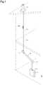
- FIG. 1is a schematic diagram of a hot water supply system according to one embodiment of the present invention.
- FIG. 2is a partially enlarged view of the hot water supply system according to one embodiment of the present invention.
- FIG. 3is a schematic diagram showing the step of introducing a conduit into an outer tube in a method for constructing the hot water supply system according to one embodiment of the present invention.
- FIG. 4is a schematic diagram showing the step of introducing the conduit into the outer tube in the method for constructing the hot water supply system according to one embodiment of the present invention.
- FIG. 5is a side view of the conduit according to one embodiment of the present invention conduit.
- FIG. 6is a front view of the conduit shown in FIG. 5 .
- FIG. 7is a sectional view taken along line A-A of FIG. 6 .
- FIG. 8is a partially enlarged view of the conduit shown in FIG. 7 .
- FIG. 9is a black and white photograph showing test results for introducing an exemplary conduit according to one embodiment of the present invention into an outer tube.
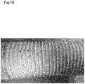
- FIG. 10is another black and white photograph showing test results for introducing a conduit of a Comparative Example into an outer tube.
- a conduit 100that is laid indoors, and used for guiding an exhaust gas discharged from a water heater 11 arranged indoors to the outdoors.
- the conduit 100is laid, so as to be bent, from the water heater 11 to an air diffusion part 13 .
- FIG. 1is a schematic diagram of a hot water supply system 10 .
- the hot water supply system 10is constructed inside a building.
- the hot water supply system 10includes a water heater 11 installed on a floor of the building; an air diffusion part 13 for exhausting a gas to the outdoors; an outer tube 15 laid between the water heater 11 and the air diffusion part 13 ; and a conduit 100 connected to the water heater 11 and the air diffusion part 13 inside the outer tube 15 .
- one end of the conduit 100is connected to an exhaust port 11 a of the water heater 11 .
- the other end of the conduit 100is connected to the air diffusion part 13 formed in a chimney on a roof.
- the outer tube 15 and the conduit 100are laid in a bent state indoors.
- a high-temperature exhaust gas from the water heater 11is discharged via the conduit 100 to the outdoors.
- the outer tube 15covers and protects the conduit 100 .
- the conduit 100is a flexible corrugated tube made of a synthetic resin, whereas the outer tube 15 is formed of a metallic hard cylindrical body.
- the outer tube 15has a bent shape formed by joining a plurality of straight cylinders 16 via elbows 17 .
- FIG. 2is a partially enlarged view of a part in the vicinity of the elbow 17 of the hot water supply system 10 .
- one screw 18is used to connect the long straight cylinder 16 to the elbow 17 .
- the elbows 17which are bent at 45 degrees are arranged at two places.
- the screw 18is attached to the wall part not at the inner side, but at the outer side of the curve, in the lower portion of the respective elbows 17 .
- the conduit 100moves to the inside of the curve more easily than to the outside of the curve.
- the screw 18penetrates the outer wall of the straight cylinder 16 and the outer wall of the elbow 17 so that the head of the screw 18 is positioned at the outer side of the elbow 17 and that a sharp tip end of the screw 18 protrudes into the straight cylinder 16 .
- the conduit 100is provided in a bent state inside the outer tube 15 so as to avoid the screw 18 , as shown in FIG. 2 .
- the hot water supply system 10is constructed by inserting the conduit 100 from an end part of the outer tube 15 and sending the conduit 100 into the outer tube 15 . More specifically, as the conduit 100 is introduced and sent through an opening of the outer tube 15 , the tip end of the conduit 100 advances inside the outer tube 15 . In the straight cylinder 16 , the conduit 100 advances linearly. Then, as shown in FIG. 3 , the conduit 100 reaches the elbow 17 , and the tip end of the conduit 100 abuts against the inclined surface of the elbow 17 . When pushed further, the conduit 100 is bent along the inclined surface of the elbow 17 . At this time, the conduit 100 is bent so as to bulge to the outside of the curve of the outer tube 15 .
- the tip end of the screw 18 and the outer surface of the conduit 100are brought into contact with each other, as shown in FIG. 4 . Then, when the conduit 100 is sent in a state where the tip end of the screw 18 is in contact with the outer surface of the conduit 100 , the outer surface of the conduit 100 is damaged. Especially, the corners of the convex portions of the conduit 100 are contacted with the tip end of the screw 18 and easily damaged.
- the conduit 100 of the present inventionis configured so that no hole is formed even if the outer surface is damaged when the tip end of the screw 18 scratches the outer surface. Also, the conduit 100 is configured so that the screw 18 would not be caught in the concave portion in the outer surface.
- FIG. 5is a schematic side view of the conduit 100 .
- FIG. 6is a front view of the conduit 100 .
- FIG. 7is a sectional view of the conduit 100 taken along line A-A.
- FIG. 8is a partially enlarged sectional view of the conduit 100 .
- the conduit 100is a long, bellows-shaped flexible tube made of a synthetic resin.
- the conduit 100has a circular lateral section.
- the conduit 100has an inner surface and an outer surface, and is configured so as to have concave portions and convex portions alternately and continuously provided in the length direction and to be bendable.
- the conduit 100includes outer wall parts 101 constituting convex surfaces of the bellows and inner wall parts 103 constituting concave surfaces of the bellows.
- the outer wall part 101is a ring-shaped body having a large diameter
- the inner wall part 103is a ring-shaped body having a small diameter.
- the conduit of this embodimentcan be molded from a resin material such as (flame-retardant) polypropylene or (flame-retardant) polyethylene.
- the outer wall part 101extends with a predetermined first width w 1 in the length direction.
- This first width w 1is a width of the outer wall part 101 on the outer surface of the conduit 100 .
- the outer wall part 101has a thickness tin the center.
- the inner wall part 103is positioned radially inside relative to the outer wall part 101 , and extends with a predetermined second width w 2 in the length direction.
- This second width w 2is a width of the inner wall part 103 on the outer surface of the conduit 100 .
- the second width w 2is greater than the first width w 1 .
- the side wall part 105has a height h 1 from the outer surface of the inner wall part 103 to the outer surface of the outer wall part 101 .
- the outer wall parts 101 , inner wall parts 103 and side wall parts 105are alternately and continuously provided at a pitch w p in the length direction.
- a pair of protruding parts 102are formed at both ends in the length direction on the outer surface of the outer wall part 101 .
- the respective protruding parts 102have a height h 2 from the outer surface of the outer wall part 101 to their apex.
- the pair of protruding parts 102are spaced apart from each other with a third width w 3 .
- a non-ridged part of the outer wall part 101has a third width w 3 .
- the outer wall part 101has two edges that are relatively thick. Also, the edges of the respective protruding parts 102 are curved.
- the outer diameter D of the conduit 100is defined as a diameter on the outer surfaces of the protruding parts 102 of the conduit 100 .
- a ridged part 107is formed to be ridged on the outer surface of the inner wall part 103 .
- the height h 3 of the ridged part 107is smaller than the height h 1 of the side wall part 105 .
- the ridged part 107extends annularly along the outer periphery of the conduit 100 .
- the ridged part 107has a longitudinal section which has an approximately trapezoidal shape tapered radially outward, as shown in FIG. 8 .
- the approximately trapezoidal ridged part 107includes an upper bottom part positioned on the outer side of the inner wall part 103 and a lower bottom part integrally coupled to the inner wall part 103 .
- the distance between the lower bottom part and the upper bottom partcorresponds to the height h 3 of the ridged part 107 .
- the upper bottom parthas a width w 4 in the length direction.
- the width w 4 of the upper bottom partis about 1 ⁇ 2 to 2 ⁇ 3 of the second width w 2 of the inner wall part 103 .
- Both side ends of the lower bottom part of the ridged part 107are positioned at both ends of the outer surface of the inner wall part 103 .
- the width of the lower bottom part of the ridged part 107is equal to the second width w 2 of the inner wall part 103 , in FIG. 8 .
- the outer surface of the conduit 100gradually changes.
- the inclined surface of the ridged part 107is formed adjacent to both of the side wall parts 105 on the outer surface of the inner wall part 103 , and a flat surface is formed approximately in the center.
- a V-shaped or wedge-shaped gapis formed between the ridged part 107 and the side wall part 105 .
- the outer surface of the conduit 100is relatively linearly formed, whereas the inner surface of the conduit 100 is slightly rounded as compared with the outer surface.
- the inner surface of the inner wall part 103defines a moderately-curved convex curve surface. This is due to the molding process (such as vacuum molding) of the conduit 100 .
- designhas been made so that the ridged part 107 is provided on the outer surface of the inner wall part 103 , thereby relatively suppressing inward bulging of the inner surface of the inner wall part 103 .
- a near-flat inner surface profile of the inner wall part 103imparts a smoother appearance to the entire inner surface of a hose, and contributes to the reduction in air resistance inside the hose. As a result, the pressure loss in the exhaust gas is alleviated.
- the inner wall part 103is formed thick as a whole, the thinnest portions are located at both ends of the inner wall part 103 (or the ridged part 107 ).
- the inner surface of the side wall part 105is inclined so that the distance between the inner surfaces of the side wall parts 105 which face each other across the outer wall part 101 becomes narrower toward the radial inside of the conduit 100 .
- the side wall part 105is thin on the side of the outer wall part 101 and is thick on the side of the inner wall part 103 .
- the thinnest portions at both ends of the inner wall part 103 and the thinnest portion at the outer side of the side wall part 105are easily bowed and deformed.
- the relatively thick outer wall part 101 and inner wall part 103are hard to bend.
- the thin portionsare bent preferentially, thereby suppressing the bending of the inner wall part 103 itself.
- (h 1 ⁇ t)affects the flexibility of the conduit 100 .
- (h 1 ⁇ t)is preferably 45% or less of the pitch w P .
- (h 1 ⁇ t)is preferably about 1.8 mm or more and about 2.2 mm or less.
- (h 1 +h 2 ⁇ h 3 )affects the easiness for the screw 18 to bite into the concave portion of the conduit 100 .
- (h 1 +h 2 ⁇ h 3 )is 46% or less of the pitch w P in order to prevent the screw 18 from being caught in the concave portion.
- (h 1 +h 2 ⁇ h 3 )is preferably about 2.3 mm or less.
- (h 1 +h 2 ⁇ h 3 )is preferably about 2.0 mm or more in view of the effects on the flexibility. Then, h 2 affects the durability of the conduit 100 when the conduit 100 is rubbed with the screw 18 .
- h 2is preferably 0.1 mm or more in order to reduce the possibility that a hole would be formed in the outer surface of the conduit 100 .
- h 2is preferably about 0.6 mm or less, more preferably about 0.4 mm or less.
- the conduit 100 of the Examplewas produced through a common vacuum molding process.
- a sheet-shaped resin material softened by heatingwas arranged around a die, and a space between the material and the die was vacuumed, so that the material was closely adhered to the die.
- a conduit made of a synthetic resinwas molded.
- the conduit 100 of the Examplehas, for example, the following dimensions.
- the conduit 100was designed on the supposition that the protrusion amount of the screw 18 was about 10 mm.
- the conduit 100 of the Examplewas subjected to a test on the resistance to scratching by a screw.
- the testwas conducted by introducing the conduit 100 into the outer tube 15 , which is bent. Specifically, the conduit 100 was pushed into the outer tube 15 laid as shown in FIGS. 1 and 2 (the outer tube 15 has elbows 17 bent at 45° and provided at two places and has two screws 18 ) with relatively strong force (0.36 kg/m) in a straight advancing direction, and then the appearance of the conduit 100 was observed.
- the protrusion amount of the screw 18 on the inner surface of the outer tube 15was 10 mm. Also, the outer tube 15 had an inner diameter of 76.2 mm (3 inches).
- a conduit having no protruding partwas used as a Comparative Example.
- the conduit of the Comparative Exampleis identical with the conduit of the Example in dimensions and shape except that the former has no protruding part.
- FIG. 9is a photograph showing the appearance of the conduit 100 of the Example after testing. It is seen that no hole is formed although the convex portions of the conduit 100 are damaged, as shown in FIG. 9 .
- FIG. 10is a photograph showing the conduit of the Comparative Example. As shown in FIG. 10 , the outer surface of the conduit is damaged, while a plurality of holes are formed in some of the damaged parts. A similar test was repeated many times, and similar results were obtained.
- the conduit of the present inventionthus has the advantage of making it difficult for a hole to be formed when the outer surface is scratched by a screw.
- the present inventionprovides a conduit having high resistance to scratching by a screw.
- the present inventionis not limited to the above embodiment, and can take various embodiments and variants.
- the conduit of the present inventionis not limited to the above application, and those skilled in the art can use the conduit in various applications.
- the conduit of the present inventionmay be used in applications including piping for air ventilation and piping of air conditioners.
- the conduit of the present inventionis not limited to the shape and dimensions of the above embodiment.
- the shape and dimensions of the Exampleare indicated for purposes of illustration, and those skilled in the art can arbitrarily change the shape and dimensions without departing from the technical scope of the present invention.
- the conduitmay have an elliptic, oval or polygonal lateral sectional shape.
Landscapes
- Engineering & Computer Science (AREA)
- General Engineering & Computer Science (AREA)
- Mechanical Engineering (AREA)
- Rigid Pipes And Flexible Pipes (AREA)
- Housings, Intake/Discharge, And Installation Of Fluid Heaters (AREA)
Abstract
Description
h1−t=1.9 mm<2.2 mm
h1+h2−h3=2.2 mm<2.3 mm
h2=0.2 mm>0.1 mm
Claims (9)
Priority Applications (2)
| Application Number | Priority Date | Filing Date | Title |
|---|---|---|---|
| US15/413,552US10605453B2 (en) | 2017-01-24 | 2017-01-24 | Conduit and hot water supply system |
| JP2017217744AJP7022568B2 (en) | 2017-01-24 | 2017-11-10 | Vessel and hot water system |
Applications Claiming Priority (1)
| Application Number | Priority Date | Filing Date | Title |
|---|---|---|---|
| US15/413,552US10605453B2 (en) | 2017-01-24 | 2017-01-24 | Conduit and hot water supply system |
Publications (2)
| Publication Number | Publication Date |
|---|---|
| US20180209645A1 US20180209645A1 (en) | 2018-07-26 |
| US10605453B2true US10605453B2 (en) | 2020-03-31 |
Family
ID=62906113
Family Applications (1)
| Application Number | Title | Priority Date | Filing Date |
|---|---|---|---|
| US15/413,552Active2038-06-26US10605453B2 (en) | 2017-01-24 | 2017-01-24 | Conduit and hot water supply system |
Country Status (2)
| Country | Link |
|---|---|
| US (1) | US10605453B2 (en) |
| JP (1) | JP7022568B2 (en) |
Cited By (1)
| Publication number | Priority date | Publication date | Assignee | Title |
|---|---|---|---|---|
| US20230243549A1 (en)* | 2022-02-03 | 2023-08-03 | Carrier Corporation | Collapsible coaxial flex duct |
Families Citing this family (3)
| Publication number | Priority date | Publication date | Assignee | Title |
|---|---|---|---|---|
| US20190128518A1 (en)* | 2017-10-26 | 2019-05-02 | Olympia Chimney Supply, Inc. | Flexible Chimney Liner |
| US11828482B2 (en)* | 2020-05-08 | 2023-11-28 | Shawn F D Perry | One pipe or two pipe flue gas and combustion air system |
| JP2023122015A (en)* | 2022-02-22 | 2023-09-01 | 積水化学工業株式会社 | Telescopic corrugated pipe and composite pipe having the same |
Citations (36)
| Publication number | Priority date | Publication date | Assignee | Title |
|---|---|---|---|---|
| US2073335A (en)* | 1935-10-05 | 1937-03-09 | Connell Karl | Breathing tube |
| US2707491A (en)* | 1951-08-17 | 1955-05-03 | Gen Motors Corp | Flexible tubing |
| US3273600A (en)* | 1963-06-10 | 1966-09-20 | Air Reduction | Flexible tube |
| GB1092150A (en)* | 1965-10-19 | 1967-11-22 | Bjorn Large | A method of producing ribbed tubes of deformable material |
| US4310946A (en)* | 1979-01-19 | 1982-01-19 | Plastiflex Company International | Electromagnetic energy-carrying tube and fabrication method therefor, and the combination thereof with suction cleaning apparatus |
| US4420019A (en)* | 1982-04-05 | 1983-12-13 | Dillon Joseph C | Flexible, non-kinkable hose and method for making the same |
| US4589448A (en)* | 1984-07-25 | 1986-05-20 | Electrolux Corporation | Flexible helically wound hose with hinged strip |
| US4712515A (en)* | 1983-09-30 | 1987-12-15 | Francois Couprie | Device for evacuating into the ambient air combustion products from a condensation boiler |
| US4860797A (en)* | 1987-05-21 | 1989-08-29 | Fabricated Plastics, Inc. | Reinforced strip and flexible hoses produced therewith |
| US5165732A (en)* | 1991-04-05 | 1992-11-24 | Simpson Dura Vent Company, Inc. | Gas appliance connection |
| US5329973A (en)* | 1990-10-24 | 1994-07-19 | Shiro Kanao | Rigid polyvinyl chloride pipe |
| US5343738A (en)* | 1992-10-16 | 1994-09-06 | Furon Company | Double walled containment fuel transfer hose |
| US5456291A (en)* | 1987-09-01 | 1995-10-10 | Iwk Regler Und Kompensatoren Gmbh | Conduit metallic knit element for exhaust gas systems |
| US5660912A (en)* | 1993-07-14 | 1997-08-26 | Rib Loc Australia Pty Ltd | Plastic profiled strip forming helically wound tube using hinged flap for jointing |
| US6062608A (en)* | 1998-07-29 | 2000-05-16 | Marco Manufacturing, Inc. | Coaxial flue-system for direct-vent fireplaces |
| US6076862A (en)* | 1998-08-24 | 2000-06-20 | Selkirk, Inc. | Concentric snap-together direct vent structure and associated fabrication methods |
| US6234163B1 (en)* | 1998-04-30 | 2001-05-22 | John Trevor Garrod | Flue ducting for atmospheric boilers |
| EP1227277A2 (en)* | 2001-01-26 | 2002-07-31 | Willi Skoberne | Exhaust pipe for combustion devices in buildings |
| US6634352B2 (en)* | 2001-01-17 | 2003-10-21 | American Metal Products Company | Direct venting vent pipe |
| US6830076B1 (en)* | 2000-08-02 | 2004-12-14 | The Boeing Company | Self-compensating hybrid combination ducts |
| US20050229923A1 (en)* | 2003-01-21 | 2005-10-20 | Michael Barry | Liner adaptor for chimney |
| US20070141284A1 (en)* | 2005-12-19 | 2007-06-21 | Saint-Gobain Performance Plastics Corporation | Smooth bore flexible fluid conduit |
| US20100154914A1 (en)* | 2006-03-24 | 2010-06-24 | Steven Liebson | Semi-rigid flexible duct |
| US7798891B2 (en)* | 2007-04-11 | 2010-09-21 | Don Park Limited Partnership | Chimney lining and venting apparatus for use with emissions from an appliance, and method of assembly |
| US20120255329A1 (en)* | 2011-04-06 | 2012-10-11 | Bsh Home Appliances Corporation | Drain hose for a washer |
| US8689837B1 (en)* | 2009-12-10 | 2014-04-08 | Jeffrey E. Smith | Low profile downspout extension and landscape drainage assembly |
| US20140130929A1 (en)* | 2012-11-07 | 2014-05-15 | Euramax International, Inc. | Seamless helically corrugated tubes and methods of manufacture |
| US8776836B2 (en)* | 2001-11-24 | 2014-07-15 | Ragner Technology Corporation | Linearly retractable pressure hose structure |
| US20140209087A1 (en)* | 2013-01-25 | 2014-07-31 | M&G DuraVent, Inc. | Dual category venting system |
| US20140273703A1 (en)* | 2013-03-13 | 2014-09-18 | Merit Medical Systems, Inc. | Serially deposited fiber materials and associated devices and methods |
| US8881689B2 (en)* | 2011-04-26 | 2014-11-11 | Noritz Corporation | Exhaust adapter and combustion apparatus having the same |
| US9140450B2 (en)* | 2009-04-21 | 2015-09-22 | M&G DuraVent, Inc. | Retrofitted corrosive resistant venting system |
| US20150330535A1 (en)* | 2014-05-13 | 2015-11-19 | Hawkeye Concrete Products Co. | Liner for concrete article |
| US20150345671A1 (en)* | 2013-01-10 | 2015-12-03 | Medin Medical Innovations Gmbh | Fluid Hose Device |
| US9239121B1 (en)* | 2011-04-15 | 2016-01-19 | Ragner Technology Corporation | Valley shaping reinforcement |
| US20160060873A1 (en) | 2014-09-02 | 2016-03-03 | Noritz Corporation | Method of installing exhaust tube |
Family Cites Families (5)
| Publication number | Priority date | Publication date | Assignee | Title |
|---|---|---|---|---|
| JPS5592984U (en)* | 1978-11-15 | 1980-06-27 | ||
| JPS5756279U (en)* | 1980-09-19 | 1982-04-02 | ||
| JP2002181257A (en) | 2000-12-14 | 2002-06-26 | Piolax Inc | Resin corrugated tube |
| JP4218906B2 (en) | 2002-06-24 | 2009-02-04 | タイガースポリマー株式会社 | Conduit hose |
| US8997793B2 (en) | 2011-06-15 | 2015-04-07 | U.S. Farathane Corporation | Flexible conduit for use in fresh air intake and gas vapor outlet incorporated into a vehicle fuel tank to eliminate whistling within the conduit |
- 2017
- 2017-01-24USUS15/413,552patent/US10605453B2/enactiveActive
- 2017-11-10JPJP2017217744Apatent/JP7022568B2/enactiveActive
Patent Citations (38)
| Publication number | Priority date | Publication date | Assignee | Title |
|---|---|---|---|---|
| US2073335A (en)* | 1935-10-05 | 1937-03-09 | Connell Karl | Breathing tube |
| US2707491A (en)* | 1951-08-17 | 1955-05-03 | Gen Motors Corp | Flexible tubing |
| US3273600A (en)* | 1963-06-10 | 1966-09-20 | Air Reduction | Flexible tube |
| GB1092150A (en)* | 1965-10-19 | 1967-11-22 | Bjorn Large | A method of producing ribbed tubes of deformable material |
| US4310946A (en)* | 1979-01-19 | 1982-01-19 | Plastiflex Company International | Electromagnetic energy-carrying tube and fabrication method therefor, and the combination thereof with suction cleaning apparatus |
| US4420019A (en)* | 1982-04-05 | 1983-12-13 | Dillon Joseph C | Flexible, non-kinkable hose and method for making the same |
| US4712515A (en)* | 1983-09-30 | 1987-12-15 | Francois Couprie | Device for evacuating into the ambient air combustion products from a condensation boiler |
| US4589448A (en)* | 1984-07-25 | 1986-05-20 | Electrolux Corporation | Flexible helically wound hose with hinged strip |
| US4860797A (en)* | 1987-05-21 | 1989-08-29 | Fabricated Plastics, Inc. | Reinforced strip and flexible hoses produced therewith |
| US5456291A (en)* | 1987-09-01 | 1995-10-10 | Iwk Regler Und Kompensatoren Gmbh | Conduit metallic knit element for exhaust gas systems |
| US5329973A (en)* | 1990-10-24 | 1994-07-19 | Shiro Kanao | Rigid polyvinyl chloride pipe |
| US5165732A (en)* | 1991-04-05 | 1992-11-24 | Simpson Dura Vent Company, Inc. | Gas appliance connection |
| US5343738A (en)* | 1992-10-16 | 1994-09-06 | Furon Company | Double walled containment fuel transfer hose |
| US5660912A (en)* | 1993-07-14 | 1997-08-26 | Rib Loc Australia Pty Ltd | Plastic profiled strip forming helically wound tube using hinged flap for jointing |
| US6234163B1 (en)* | 1998-04-30 | 2001-05-22 | John Trevor Garrod | Flue ducting for atmospheric boilers |
| US6062608A (en)* | 1998-07-29 | 2000-05-16 | Marco Manufacturing, Inc. | Coaxial flue-system for direct-vent fireplaces |
| US6076862A (en)* | 1998-08-24 | 2000-06-20 | Selkirk, Inc. | Concentric snap-together direct vent structure and associated fabrication methods |
| US6830076B1 (en)* | 2000-08-02 | 2004-12-14 | The Boeing Company | Self-compensating hybrid combination ducts |
| US6634352B2 (en)* | 2001-01-17 | 2003-10-21 | American Metal Products Company | Direct venting vent pipe |
| EP1227277A2 (en)* | 2001-01-26 | 2002-07-31 | Willi Skoberne | Exhaust pipe for combustion devices in buildings |
| US8776836B2 (en)* | 2001-11-24 | 2014-07-15 | Ragner Technology Corporation | Linearly retractable pressure hose structure |
| US10309560B2 (en)* | 2001-11-24 | 2019-06-04 | Ragner Technology Corporation | Multi-layer pressure actuated extendable hose |
| US9371944B2 (en)* | 2001-11-24 | 2016-06-21 | Ragner Technology Corporation | Multi-layer pressure actuated extendable hose |
| US20050229923A1 (en)* | 2003-01-21 | 2005-10-20 | Michael Barry | Liner adaptor for chimney |
| US20070141284A1 (en)* | 2005-12-19 | 2007-06-21 | Saint-Gobain Performance Plastics Corporation | Smooth bore flexible fluid conduit |
| US20100154914A1 (en)* | 2006-03-24 | 2010-06-24 | Steven Liebson | Semi-rigid flexible duct |
| US7798891B2 (en)* | 2007-04-11 | 2010-09-21 | Don Park Limited Partnership | Chimney lining and venting apparatus for use with emissions from an appliance, and method of assembly |
| US9140450B2 (en)* | 2009-04-21 | 2015-09-22 | M&G DuraVent, Inc. | Retrofitted corrosive resistant venting system |
| US8689837B1 (en)* | 2009-12-10 | 2014-04-08 | Jeffrey E. Smith | Low profile downspout extension and landscape drainage assembly |
| US20120255329A1 (en)* | 2011-04-06 | 2012-10-11 | Bsh Home Appliances Corporation | Drain hose for a washer |
| US9239121B1 (en)* | 2011-04-15 | 2016-01-19 | Ragner Technology Corporation | Valley shaping reinforcement |
| US8881689B2 (en)* | 2011-04-26 | 2014-11-11 | Noritz Corporation | Exhaust adapter and combustion apparatus having the same |
| US20140130929A1 (en)* | 2012-11-07 | 2014-05-15 | Euramax International, Inc. | Seamless helically corrugated tubes and methods of manufacture |
| US20150345671A1 (en)* | 2013-01-10 | 2015-12-03 | Medin Medical Innovations Gmbh | Fluid Hose Device |
| US20140209087A1 (en)* | 2013-01-25 | 2014-07-31 | M&G DuraVent, Inc. | Dual category venting system |
| US20140273703A1 (en)* | 2013-03-13 | 2014-09-18 | Merit Medical Systems, Inc. | Serially deposited fiber materials and associated devices and methods |
| US20150330535A1 (en)* | 2014-05-13 | 2015-11-19 | Hawkeye Concrete Products Co. | Liner for concrete article |
| US20160060873A1 (en) | 2014-09-02 | 2016-03-03 | Noritz Corporation | Method of installing exhaust tube |
Cited By (1)
| Publication number | Priority date | Publication date | Assignee | Title |
|---|---|---|---|---|
| US20230243549A1 (en)* | 2022-02-03 | 2023-08-03 | Carrier Corporation | Collapsible coaxial flex duct |
Also Published As
| Publication number | Publication date |
|---|---|
| JP7022568B2 (en) | 2022-02-18 |
| JP2018119674A (en) | 2018-08-02 |
| US20180209645A1 (en) | 2018-07-26 |
Similar Documents
| Publication | Publication Date | Title |
|---|---|---|
| US10605453B2 (en) | Conduit and hot water supply system | |
| US10544884B2 (en) | Sealing system for an annular space | |
| KR100959242B1 (en) | A resin tube with multiple inner conduits | |
| JP2017198338A (en) | Cable protective pipe and joint | |
| CN206112284U (en) | FRPP double -wall corrugated pipe | |
| KR101553714B1 (en) | flexible duct for Piping | |
| CN202132621U (en) | Anti-dead-folding high pressure connecting hose | |
| KR102136097B1 (en) | Pipe for protecting optical cable | |
| KR20140116829A (en) | Fixed band in flexible duct for Piping | |
| JP2011511914A5 (en) | ||
| KR101169600B1 (en) | Corrugated pipe having double wall | |
| CN1505230A (en) | Connection structures for cable ducts | |
| JP6030881B2 (en) | Corrugated plastic tube | |
| CN107091382B (en) | Self-locking rigid pipe connector with inner joint | |
| FI115664B (en) | connecting portion | |
| CN206861095U (en) | Stereoplasm tube connecting structure | |
| CN110566757B (en) | Composite pipe and production method thereof | |
| JP2010121744A (en) | Corrugated synthetic resin pipe and its connecting method | |
| US20050155209A1 (en) | Positive pipe interlock | |
| JP2006009811A (en) | Flexible tube and optical fiber bundle using the same | |
| CN216813188U (en) | Novel waterproof sleeve with dual waterproof function | |
| CN210141414U (en) | Steel belt buckle flexible interface winding solid wall pipe | |
| CN211901988U (en) | Anti-collision anti-drop metal hose joint | |
| CN210141388U (en) | Flexible multi-seal winding solid-wall pipe with buckle ring lock interface | |
| CN107906286A (en) | A kind of snap ring positions formula gas bellows |
Legal Events
| Date | Code | Title | Description |
|---|---|---|---|
| AS | Assignment | Owner name:NORITZ CORPORATION, JAPAN Free format text:ASSIGNMENT OF ASSIGNORS INTEREST;ASSIGNORS:SUGATANI, MASAKI;NAGANO, TAKANORI;MATSUNAGA, HIRONAO;AND OTHERS;REEL/FRAME:041060/0680 Effective date:20170120 Owner name:MIRAI INDUSTRY CO.,LTD., JAPAN Free format text:ASSIGNMENT OF ASSIGNORS INTEREST;ASSIGNORS:MATSUDA, SHOHEI;KAWAMURA, HIROKAZU;REEL/FRAME:041061/0210 Effective date:20170119 Owner name:LIVING ENGINEERING CO., LTD., JAPAN Free format text:ASSIGNMENT OF ASSIGNORS INTEREST;ASSIGNORS:SATO, YASUHIDE;KANAMOTO, KIYOMI;REEL/FRAME:041468/0895 Effective date:20170123 | |
| STPP | Information on status: patent application and granting procedure in general | Free format text:DOCKETED NEW CASE - READY FOR EXAMINATION | |
| AS | Assignment | Owner name:TOKYO GAS LIVING ENGINEERING CO., LTD.,, JAPAN Free format text:CHANGE OF NAME;ASSIGNOR:LIVING ENGINEERING CO., LTD.;REEL/FRAME:047249/0979 Effective date:20180604 | |
| AS | Assignment | Owner name:TOKYO GAS LIVING ENGINEERING CO., LTD., JAPAN Free format text:CORRECTIVE ASSIGNMENT TO CORRECT THE ASSIGNEE NAME PREVIOUSLY RECORDED AT REEL: 047249 FRAME: 0979. ASSIGNOR(S) HEREBY CONFIRMS THE CHANGE OF NAME;ASSIGNOR:LIVING ENGINEERING CO., LTD.;REEL/FRAME:047310/0613 Effective date:20180604 | |
| STPP | Information on status: patent application and granting procedure in general | Free format text:NON FINAL ACTION MAILED | |
| STPP | Information on status: patent application and granting procedure in general | Free format text:RESPONSE TO NON-FINAL OFFICE ACTION ENTERED AND FORWARDED TO EXAMINER | |
| STPP | Information on status: patent application and granting procedure in general | Free format text:NOTICE OF ALLOWANCE MAILED -- APPLICATION RECEIVED IN OFFICE OF PUBLICATIONS | |
| STPP | Information on status: patent application and granting procedure in general | Free format text:PUBLICATIONS -- ISSUE FEE PAYMENT RECEIVED | |
| STPP | Information on status: patent application and granting procedure in general | Free format text:PUBLICATIONS -- ISSUE FEE PAYMENT VERIFIED | |
| STCF | Information on status: patent grant | Free format text:PATENTED CASE | |
| AS | Assignment | Owner name:TOKYO GAS RENOVATION CO., LTD., JAPAN Free format text:ASSIGNMENT OF ASSIGNORS INTEREST;ASSIGNOR:TOKYO GAS LIVING ENGINEERING CO., LTD.;REEL/FRAME:053971/0213 Effective date:20200713 | |
| MAFP | Maintenance fee payment | Free format text:PAYMENT OF MAINTENANCE FEE, 4TH YEAR, LARGE ENTITY (ORIGINAL EVENT CODE: M1551); ENTITY STATUS OF PATENT OWNER: LARGE ENTITY Year of fee payment:4 |