US10605347B2 - Ring clip assembly - Google Patents
Ring clip assemblyDownload PDFInfo
- Publication number
- US10605347B2 US10605347B2US15/268,258US201615268258AUS10605347B2US 10605347 B2US10605347 B2US 10605347B2US 201615268258 AUS201615268258 AUS 201615268258AUS 10605347 B2US10605347 B2US 10605347B2
- Authority
- US
- United States
- Prior art keywords
- ring
- ring clip
- shaft
- assembly
- clip
- Prior art date
- Legal status (The legal status is an assumption and is not a legal conclusion. Google has not performed a legal analysis and makes no representation as to the accuracy of the status listed.)
- Active, expires
Links
Images


Classifications
- F—MECHANICAL ENGINEERING; LIGHTING; HEATING; WEAPONS; BLASTING
- F16—ENGINEERING ELEMENTS AND UNITS; GENERAL MEASURES FOR PRODUCING AND MAINTAINING EFFECTIVE FUNCTIONING OF MACHINES OR INSTALLATIONS; THERMAL INSULATION IN GENERAL
- F16D—COUPLINGS FOR TRANSMITTING ROTATION; CLUTCHES; BRAKES
- F16D1/00—Couplings for rigidly connecting two coaxial shafts or other movable machine elements
- F16D1/06—Couplings for rigidly connecting two coaxial shafts or other movable machine elements for attachment of a member on a shaft or on a shaft-end
- F16D1/08—Couplings for rigidly connecting two coaxial shafts or other movable machine elements for attachment of a member on a shaft or on a shaft-end with clamping hub; with hub and longitudinal key
- F16D1/0852—Couplings for rigidly connecting two coaxial shafts or other movable machine elements for attachment of a member on a shaft or on a shaft-end with clamping hub; with hub and longitudinal key with radial clamping between the mating surfaces of the hub and shaft
- F16D1/0858—Couplings for rigidly connecting two coaxial shafts or other movable machine elements for attachment of a member on a shaft or on a shaft-end with clamping hub; with hub and longitudinal key with radial clamping between the mating surfaces of the hub and shaft due to the elasticity of the hub (including shrink fits)
- F—MECHANICAL ENGINEERING; LIGHTING; HEATING; WEAPONS; BLASTING
- F16—ENGINEERING ELEMENTS AND UNITS; GENERAL MEASURES FOR PRODUCING AND MAINTAINING EFFECTIVE FUNCTIONING OF MACHINES OR INSTALLATIONS; THERMAL INSULATION IN GENERAL
- F16D—COUPLINGS FOR TRANSMITTING ROTATION; CLUTCHES; BRAKES
- F16D7/00—Slip couplings, e.g. slipping on overload, for absorbing shock
- F16D7/02—Slip couplings, e.g. slipping on overload, for absorbing shock of the friction type
- F16D7/021—Slip couplings, e.g. slipping on overload, for absorbing shock of the friction type with radially applied torque-limiting friction surfaces
- F—MECHANICAL ENGINEERING; LIGHTING; HEATING; WEAPONS; BLASTING
- F16—ENGINEERING ELEMENTS AND UNITS; GENERAL MEASURES FOR PRODUCING AND MAINTAINING EFFECTIVE FUNCTIONING OF MACHINES OR INSTALLATIONS; THERMAL INSULATION IN GENERAL
- F16H—GEARING
- F16H1/00—Toothed gearings for conveying rotary motion
- F16H1/02—Toothed gearings for conveying rotary motion without gears having orbital motion
- F16H1/04—Toothed gearings for conveying rotary motion without gears having orbital motion involving only two intermeshing members
- F—MECHANICAL ENGINEERING; LIGHTING; HEATING; WEAPONS; BLASTING
- F16—ENGINEERING ELEMENTS AND UNITS; GENERAL MEASURES FOR PRODUCING AND MAINTAINING EFFECTIVE FUNCTIONING OF MACHINES OR INSTALLATIONS; THERMAL INSULATION IN GENERAL
- F16H—GEARING
- F16H19/00—Gearings comprising essentially only toothed gears or friction members and not capable of conveying indefinitely-continuing rotary motion
- F16H19/02—Gearings comprising essentially only toothed gears or friction members and not capable of conveying indefinitely-continuing rotary motion for interconverting rotary or oscillating motion and reciprocating motion
- F16H19/04—Gearings comprising essentially only toothed gears or friction members and not capable of conveying indefinitely-continuing rotary motion for interconverting rotary or oscillating motion and reciprocating motion comprising a rack
- F—MECHANICAL ENGINEERING; LIGHTING; HEATING; WEAPONS; BLASTING
- F16—ENGINEERING ELEMENTS AND UNITS; GENERAL MEASURES FOR PRODUCING AND MAINTAINING EFFECTIVE FUNCTIONING OF MACHINES OR INSTALLATIONS; THERMAL INSULATION IN GENERAL
- F16H—GEARING
- F16H55/00—Elements with teeth or friction surfaces for conveying motion; Worms, pulleys or sheaves for gearing mechanisms
- F16H55/02—Toothed members; Worms
- F16H55/17—Toothed wheels
- F—MECHANICAL ENGINEERING; LIGHTING; HEATING; WEAPONS; BLASTING
- F16—ENGINEERING ELEMENTS AND UNITS; GENERAL MEASURES FOR PRODUCING AND MAINTAINING EFFECTIVE FUNCTIONING OF MACHINES OR INSTALLATIONS; THERMAL INSULATION IN GENERAL
- F16H—GEARING
- F16H57/00—General details of gearing
- F16H57/0018—Shaft assemblies for gearings
- F16H57/0025—Shaft assemblies for gearings with gearing elements rigidly connected to a shaft, e.g. securing gears or pulleys by specially adapted splines, keys or methods
- F—MECHANICAL ENGINEERING; LIGHTING; HEATING; WEAPONS; BLASTING
- F16—ENGINEERING ELEMENTS AND UNITS; GENERAL MEASURES FOR PRODUCING AND MAINTAINING EFFECTIVE FUNCTIONING OF MACHINES OR INSTALLATIONS; THERMAL INSULATION IN GENERAL
- F16H—GEARING
- F16H1/00—Toothed gearings for conveying rotary motion
- F16H1/02—Toothed gearings for conveying rotary motion without gears having orbital motion
- F16H1/04—Toothed gearings for conveying rotary motion without gears having orbital motion involving only two intermeshing members
- F16H1/06—Toothed gearings for conveying rotary motion without gears having orbital motion involving only two intermeshing members with parallel axes
Definitions
- friction torque or linear force resistancein combination with a variety of functional configurations.
- Such combinationscan be difficult to accommodate in small package sizes, and can be complicated to assemble and construct. For these and other reasons, there is a need for the invention.
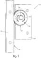
- FIG. 1is a perspective view of ring clip friction device in accordance with one embodiment.
- FIG. 2is a perspective view of a ring clip assembly with multiple ring clips in accordance with one embodiment.
- FIG. 3is a perspective view of a ring clip assembly in accordance with one embodiment.
- FIG. 4is a front view of a ring clip in accordance with one embodiment.
- FIG. 5Ais a front view of a ring clip in accordance with one embodiment.
- FIG. 5Bis a front view of a ring clip in accordance with one embodiment.
- FIG. 6is a perspective view of ring clip friction device in accordance with one embodiment.
- FIG. 7is a perspective view of ring clip friction device in accordance with one embodiment.
- FIG. 8is a perspective view of ring clip friction device in accordance with one embodiment.
- FIG. 1illustrates ring clip friction device 10 in accordance with one embodiment.
- ring clip friction device 10includes first member 12 , second member 14 and ring clip assembly 20 .
- First member 12includes first member transmission elements 18 along at least one of its sides.
- Ring clip assembly 20includes a plurality of ring clips 22 mounted over shaft 16 , which in turn is fixed to, and extends from, second member 14 .
- each of ring clips 22have ring clip transmission elements 24 on the outer edge of the ring clips 22 .
- ring clip assembly 20affords a smooth linear force resistance profile with the relative linear movement of first and second members 12 and 14 .
- first member 12is fixed or mounted to a stationary base.
- Second member 14is then configured to move linearly relative to the stationary first member 12 .
- Each of ring clips 22are press fit over shaft 16 , such that sufficient force must be applied to ring clip 22 to overcome its interference with shaft 16 in order to make ring clips 22 rotate over shaft 16 .
- Ring clip transmission elements 24are then engaged with first member transmission elements 18 .
- ring clip transmission elements 24 and first member transmission elements 18are interlocking gear teeth, such as cycloidal, involute or sprocket teeth.
- first and second members 12 and 14forces rotation of ring clips 22 , and the torque generated by the interference between ring clips 22 and shaft 16 provides a relatively consistent and repeatable linear force profile that is useful in many applications.
- This favorable torque or linear force profileis achieved in a relatively streamlined package. Rather than have a torque device in one housing, and then connecting a power transmission device to the torque device, ring clip friction device 10 provides both the torque and transmission functionality in a relatively thin overall package.
- FIGS. 2 and 3illustrate ring clip assembly 20 in accordance with one embodiment.
- Ring clip assembly 20includes ring clips 22 and shaft 16 .
- a plurality of ring clips 22are mounted over shaft 16
- a single ring clip 22is mounted over shaft 16 .
- the number of ring clips 22 used in any ring clip assembly 20can be varied in order to adjust the amount of torque generated in the particular application in which ring clip assembly 20 is used. The more ring clips 22 used, the more torque that will be generated in the ring clip assembly 20 .
- ring clips 22include ring portion 26 , arms 28 , and slot 27 defined between ring portion 26 and arms 28 .
- the outer surface 16 a of shaft 16has diameter greater than the diameter of the opening defined within arms 28 , such that arms 28 are in an interference engagement with shaft 16 .
- Ring clip transmission elements 24are carried on the outer surface of ring portion 26 and configured for engagement with other transmission elements as previously described.
- ring portion 26forms a fully closed circle, thereby containing arms 28 .
- slot 27extends radially around arms 28 sufficiently that arms 28 are allowed to fully flex without contact from the surrounding ring portion 26 .
- arms 28are in an interference fit with shaft 16 , arms 28 must be free to flex as ring clip 22 is installed onto and rotated about shaft 16 in order for torque assembly 20 to have a relatively consistent and repeatable torque profile over the entire rotation of ring clip 22 . If arms 28 are constrained or do not have enough radial length, the torque profile of the assembly would be uneven, unpredictable, and non-repeatable.
- FIG. 4illustrates clip 22 in accordance with one embodiment.
- Ring clip 22can be used in a ring clip assembly with a shaft, such as ring clip assembly 20 and shaft 16 in FIGS. 1-3 .
- Ring clip 22includes ring portion 26 , arms 28 , and slot 27 .
- Ring clip transmission elements 24are carried on the outer surface of ring portion 26 .
- Ring portion 26is a closed and circular shape, fully enclosing arms 28 .
- Arms 28define aperture 29 and are spaced apart by opening 28 a .
- Arms 28are spaced apart from ring portion 26 throughout the entire slot 27 between slot ends 27 a and 27 b . Outside slot 27 , arms 28 and ring portion 26 are coupled together.
- slot 27has a radial span ⁇ 27 configured to be long enough to ensure that the arms 28 have sufficient length within slot 27 to both substantially surround shaft 16 and to be free to radially flex without outer contact as shaft 16 rotates relative to ring clip 22 .
- the radial span ⁇ 27 of slot 27is configured to be 300° between slot ends 27 a and 27 b .
- arms 28can be configured with sufficient length to substantially surround shaft 16 in an interference fit, yet still be able to radially flex without contact with ring portion 26 , which surrounds them.
- arms 28are too short or configured to be attached or otherwise interfere with ring portion 26 , then they will not have sufficient flex relative to shaft 16 , and accordingly, the ring clip assembly will not have a smooth or predictable torque profile.
- the radial span ⁇ 27 of slot 27must be configured to be at least 270° between slot ends 27 a and 27 b in order to afford ring clip assembly 20 with a relatively consistent and repeatable torque profile.
- ring clip 22includes two arm sections 28 , which are separated by opening 28 a .
- opening 28 aprovides opening 28 a between them ensures that arms 28 are able to flex as shaft 16 rotates relative to ring clip 22 . If a single arm 28 were to completely surround shaft 16 without an opening, ring clip assembly 20 would not have a consistent and repeatable torque or linear force resistance profile.
- each of arm sections 28is of equal length, such that ring clip produces substantially symmetrical torque or linear force resistance. In this way, resistance to the relative rotation of shaft 16 and clip 22 is substantially the same for either direction of relative rotation.
- FIG. 5Aillustrates ring clip 42 in accordance with one embodiment.
- Ring clip 42can be used in a ring clip assembly with a shaft, such as ring clip assembly 20 and shaft 16 in FIGS. 1-3 .
- Ring clip 42include ring portion 46 , arms 48 , and slot 47 .
- Ring clip transmission elements 44are carried on the outer surface of ring portion 46 .
- Ring portion 46is a closed circular shape, fully enclosing arms 48 .
- Arms 48define aperture 49 and are spaced apart by opening 48 a .
- Arms 48are spaced apart from ring portion 46 throughout the entire slot 47 between slot ends 47 a and 47 b . Outside slot 47 , arms 48 and ring portion 46 are coupled together.
- slot 47 of ring clip 42has a radial length ⁇ 47 configured long enough to ensure that the arms 48 have sufficient length within slot 47 to both substantially surround shaft 16 and to be free to radially flex without outer contact as shaft 16 rotates relative to ring clip 42 .
- arms 48have sufficient length to substantially surround shaft 16 in an interference fit, yet still are able to radially flex without contact with ring portion 46 , which surrounds them.
- arms 48are of unequal length on either side of opening 48 a .
- ring clip 42generates “asymmetrical torque,” that is, torque generated by rotation of shaft 16 within aperture 49 in one direction is not equal to the torque generated by rotation of shaft 16 within aperture 49 in the opposite direction.
- This asymmetrical torque profilemay be useful in a variety of applications. For example, when ring clip 42 is used in a ring clip assembly that is attached to facilitate movement of one member to another and gravity will assists such movement in one direction and resists it in another, the asymmetrical torque profile may be useful to provide a more overall balanced system performance.
- ring clip transmission elements 44are interlocking gear teeth, such as cycloidal, involute or sprocket teeth. In other embodiments, ring clip transmission elements 44 are a smooth outer surface that frictionally locks with other transmission elements to transmit power to or from ring clips 42 .
- FIG. 5Billustrates ring clip 52 in accordance with one embodiment.
- Ring clip 52can be used in a ring clip assembly with a shaft, such as ring clip assembly 20 and shaft 16 in FIGS. 1-3 .
- Ring clip 52include ring portion 56 , arm 58 , and slot 57 .
- Ring clip transmission elements 54are carried on the outer surface of ring portion 56 .
- Ring portion 56is a closed circular shape, fully enclosing arm 58 .
- Arm 58defines aperture 59 and further defines an opening 58 a .
- Arm 58is spaced apart from ring portion 56 throughout the entire slot 57 between slot ends 57 a and 57 b . Outside slot 57 , arm 58 and ring portion 56 are coupled together.
- slot 57 of ring clip 52has a radial span ⁇ 57 configured long enough to ensure that arm 58 has sufficient length within slot 57 to both substantially surround shaft 16 and to be free to radially flex without outer contact as shaft 16 rotates relative to ring clip 52 .
- arm 58has sufficient length to substantially surround shaft 16 in an interference fit, yet still is able to radially flex without contact with ring portion 56 , which surrounds it.
- Ring clip 52also includes an arm 58 where the opening 58 a is provided in an unbalanced location and with an uneven width. As with ring clip 42 above, this unique configuration is useful in many applications.
- FIG. 6illustrates ring clip friction device 110 in accordance with one embodiment.
- ring clip friction device 110includes first member 112 , second member 114 and ring clip assembly 120 .
- First member 112includes first member transmission elements 118 along at least one of its sides.
- Ring clip assembly 120includes a plurality of ring clips 122 mounted over shaft 116 , which in turn is fixed to, and extends from, second member 114 .
- each of ring clips 122have ring clip transmission elements 124 on the outer edge of the ring clips 122 .
- rollers 130are mounted to second member 114 and are located on either side of first member 112 thereby securing first member between rollers 130 .
- first member 112is, or is secured to, a seat back and second member 114 is a head rest for the seat back.
- the outer edges of first member 112are secured between rollers 130 , which in turn are mounted to second member 114 such that second member 114 (the headrest) can be adjusted up and down relative to first member 112 (the seat).
- Ring clip assembly 120is then coupled between first and second members 112 and 114 in order to give a relatively consistent and repeatable linear force resistance/user force profile during that up-and-down adjustment.
- Shaft 116is fixed to second member 114 and one or more ring clips 122 are pressed over shaft 116 .
- the ring clip transmission elements 124 on the outer edge of the ring clips 122are mated with the first member transmission elements 118 of first member 112 .
- the respective transmission elementsare gear teeth. In this way, relative movement of first and second members 112 and 114 forces movement of ring clip transmission elements 124 by first member transmission elements and rotates ring clips 122 over shaft 116 . This produces relatively consistent and repeatable torque or linear force resistance between first and second members 112 and 114 as they move relative to each other.
- Ring clip assembly 120may include any of a variety of ring clips, such as any of ring clips 22 , 42 and 52 described above. Ring clip 22 has symmetrical arms 28 of equal length and will provide the same force in either direction, up or down. Ring clips 42 and 52 may be desirable in some embodiments, especially where second member 114 (the headrest) has substantial weight. As such, it may be desirable for torque or linear force resistance assembly to have asymmetrical torque or linear force resistance such that it takes more force to move second member 114 down than it takes to move it up. Although ring clip assembly 120 is illustrated coupled between a seat and headrest in FIG. 6 , the predictable torque or linear force resistance profile that it provides is useful in a variety of application moving one member relative to another.
- FIG. 7illustrates ring clip friction device 150 in accordance with one embodiment.
- ring clip friction device 150includes ring clip assembly 152 and input assembly 154 .
- Ring clip assembly 152includes a ring clip 160 mounted over output shaft 165 , ring clip 160 having ring clip transmission elements 164 on its outer periphery and having arms 162 in an interference fit with output shaft 165 .
- input assembly 154includes an input gear 170 fixed to input shaft 175 , input gear 170 having gear teeth 174 on its outer periphery.
- Ring clip friction device 150may include any of a variety of ring clips, such as any of ring clips 22 , 42 and 52 described above.
- ring clip friction device 150is configured as a torque transmission overload device.
- input assembly 154is coupled to an input source 171 , such as a motor, via input shaft 175 , which rotates input gear 170 in first direction D 1 . Because the respective transmission elements 174 and 164 of input gear 170 and ring clip 160 are meshed, this rotates ring clip 160 in second direction D 2 . Rotation of ring clip 160 in turn drives output shaft 165 and any output 180 that is coupled to output shaft 165 .
- ring clip assembly 152provides overload protection. If output shaft 165 cannot rotate due to the output 180 not moving, shaft 165 will then slip relative to ring clip 160 thereby providing overload protection.
- Such overload protectionis useful in a variety of applications and this embodiment allows advantages over existing technology.
- input assembly 154may include a timing belt or sprocket coupled to input shaft 175 .
- the timing belt or sprocketcan be configured to engage transmission elements 164 , such that ring clip 160 tends to rotate with the rotation of the timing belt or sprocket.
- FIG. 8illustrates ring clip friction device 200 in accordance with one embodiment.
- ring clip friction device 200includes one-way roller assembly 202 and ring clip assembly 204 .
- One-way roller assembly 202includes roller housing 203 and a plurality of rollers 220 , each of which are configured within ramped slots 222 formed in roller housing 203 .
- Ring clip assembly 204is configured within roller housing 203 and includes a plurality of ring clips 206 , each having arms 208 , which are mounted over shaft 210 in an interference fit.
- Ring clip friction device 200may include any of a variety of ring clips, such as any of ring clips 22 , 42 and 52 described above.
- ring clip friction device 200operates as a torque differential device.
- each of the plurality of rollers 220will freely roll over the outer clip periphery that is formed from the collective outer surfaces of the plurality of ring clips 206 that are stacked over shaft 210 .
- Ramped slots 222are configured on one side to allow the plurality of rollers 220 to freely roll in the direction opposite the arrows.
- the plurality of rollers 220are configured to engage the ramped slots 222 in such a way that the rollers 220 will lock in place and will no longer rotate. As such, as roller housing 203 continues to rotate in this direction after the plurality of rollers 220 are locked, the plurality of rollers 220 grip the outer periphery of the ring clips 206 and thereby rotate the ring clips 206 relative to the shaft 210 .
- roller housing 203In this way, rotation of roller housing 203 relative to shaft 210 and output 230 in the direction opposite of the arrows produces relatively low torque and resistance to rotation, whereas rotation in the direction of the arrows produces relatively high torque and resistance to rotation.
- Such a differential rotational torque or linear force resistance of housing 203 to output 230is useful in a variety of applications.
- ring clip assembly 204does not need to be configured with teeth on its outer surface to function in accordance with the embodiments to transmit rotation of ring clips to other elements.
- Transmission elements other that gear teeth on the outer perimeter of the ring clipsare also possible, such as friction contact of the circular profile of the ring clip to other elements, timing belt teeth, splines, and chain sprocket teeth.
Landscapes
- Engineering & Computer Science (AREA)
- General Engineering & Computer Science (AREA)
- Mechanical Engineering (AREA)
- Devices For Conveying Motion By Means Of Endless Flexible Members (AREA)
Abstract
Description
Claims (13)
Priority Applications (1)
| Application Number | Priority Date | Filing Date | Title |
|---|---|---|---|
| US15/268,258US10605347B2 (en) | 2015-09-16 | 2016-09-16 | Ring clip assembly |
Applications Claiming Priority (2)
| Application Number | Priority Date | Filing Date | Title |
|---|---|---|---|
| US201562219502P | 2015-09-16 | 2015-09-16 | |
| US15/268,258US10605347B2 (en) | 2015-09-16 | 2016-09-16 | Ring clip assembly |
Publications (2)
| Publication Number | Publication Date |
|---|---|
| US20170074382A1 US20170074382A1 (en) | 2017-03-16 |
| US10605347B2true US10605347B2 (en) | 2020-03-31 |
Family
ID=58257327
Family Applications (1)
| Application Number | Title | Priority Date | Filing Date |
|---|---|---|---|
| US15/268,258Active2038-02-10US10605347B2 (en) | 2015-09-16 | 2016-09-16 | Ring clip assembly |
Country Status (1)
| Country | Link |
|---|---|
| US (1) | US10605347B2 (en) |
Cited By (2)
| Publication number | Priority date | Publication date | Assignee | Title |
|---|---|---|---|---|
| US20220042589A1 (en)* | 2020-08-07 | 2022-02-10 | Ami Industries, Inc. | Laminated Rack Assembly for Powered Motion of Aircraft Seats |
| EP4001183A1 (en)* | 2020-11-19 | 2022-05-25 | Laitram, L.L.C. | Hygienic conveyor roller |
Families Citing this family (2)
| Publication number | Priority date | Publication date | Assignee | Title |
|---|---|---|---|---|
| US11168497B2 (en) | 2018-05-29 | 2021-11-09 | Magna Closures Inc. | Power actuator with self disengaging clutch unit |
| DE112022001162T5 (en)* | 2021-02-22 | 2023-12-14 | Reell Precision Manufacturing Corporation | PARALLEL AXLE FRICTION BRAKE |
Citations (67)
| Publication number | Priority date | Publication date | Assignee | Title |
|---|---|---|---|---|
| US351936A (en) | 1886-11-02 | Pivotal support for sashes | ||
| US1166551A (en) | 1914-12-21 | 1916-01-04 | Parker T Simmons | Hinge. |
| US2462304A (en) | 1946-07-18 | 1949-02-22 | Jacobs Co F L | Sun visor |
| US2605926A (en) | 1949-10-01 | 1952-08-05 | Bolta Company | Container with a hinged cover |
| US3030783A (en) | 1961-04-14 | 1962-04-24 | Associated Spring Corp | Right-hand wound, left-hand wound, compression, extension, torsion spring |
| US3213500A (en) | 1963-11-12 | 1965-10-26 | Master Mold & Die Company | Fastener |
| US3395553A (en) | 1966-04-07 | 1968-08-06 | Curtiss Wright Corp | Torque limiting drive coupling |
| US3765054A (en) | 1971-06-02 | 1973-10-16 | Wall & Leigh Thermoplastics | Frictional connecting devices |
| US4190929A (en) | 1979-02-16 | 1980-03-04 | General Bathroom Products, Inc. | Plastic hinge |
| US4227283A (en) | 1979-01-03 | 1980-10-14 | International Business Machines Corporation | Integral hinge structure |
| US4569143A (en)* | 1983-09-02 | 1986-02-11 | Marler Haley Exposystems Limited | Structural frame |
| US4688961A (en) | 1985-03-15 | 1987-08-25 | Nifco Inc. | Combination clip |
| US4790504A (en) | 1987-12-21 | 1988-12-13 | Ncr Corporation | Display support mechanism |
| US4916968A (en) | 1987-05-15 | 1990-04-17 | Okamura Corporation | Device for mounting an operating lever for a gas spring |
| US4986507A (en) | 1989-09-08 | 1991-01-22 | Arthur Chiang | Free positioning tilt unit |
| US5010983A (en) | 1988-03-04 | 1991-04-30 | Nhk Spring Co., Ltd. | Shaft locking device |
| US5018244A (en) | 1989-06-14 | 1991-05-28 | Nhk Spring Co., Ltd. | Hinge device for coupling a member rotatable to another |
| US5037231A (en) | 1988-12-21 | 1991-08-06 | Nhk Spring Co., Ltd. | Joint device for connecting two rotatable members |
| US5041818A (en) | 1990-05-21 | 1991-08-20 | Lapro Corporation | Lid with movement control device |
| US5043846A (en) | 1989-04-10 | 1991-08-27 | Seiko Epson Corporation | Pivotable display unit support structure for electronic apparatus |
| US5052078A (en) | 1986-08-29 | 1991-10-01 | Kabushiki Kaisha Toshiba | Hinge mechanism for portable electronic apparatus |
| US5064137A (en) | 1989-05-09 | 1991-11-12 | Fumito Komatsu | Fixed torque spring clutch and a winder having the same |
| US5088156A (en) | 1989-01-31 | 1992-02-18 | Kabushiki Kaisha Toshiba | Shaft lock device and portable information processing apparatus with shaft lock device |
| US5108062A (en) | 1990-09-28 | 1992-04-28 | Ncr Corporation | Pivot apparatus |
| US5197704A (en) | 1989-12-28 | 1993-03-30 | Nhk Spring Co., Ltd. | Angle adjusting device for a display device |
| US5211368A (en) | 1989-12-29 | 1993-05-18 | Nhk Spring Co., Ltd. | Angle adjusting device for a display device |
| US5219240A (en) | 1990-01-30 | 1993-06-15 | Nhk Spring Co., Ltd. | Angle adjusting device for a display device |
| US5231734A (en) | 1991-11-04 | 1993-08-03 | General Clutch Corporation | Friction hinge assembly |
| US5235494A (en) | 1992-01-16 | 1993-08-10 | The Chamberlain Group, Inc. | Electrical controller having pivotally mounted circuit board support |
| US5354028A (en) | 1989-12-28 | 1994-10-11 | Nhk Spring Co., Ltd. | Angle adjusting device for a display device |
| US5364149A (en) | 1991-02-15 | 1994-11-15 | Industrias Techno-Matic, S.A. | Retaining spring for automobile sunvisor hinges |
| US5491874A (en) | 1993-06-02 | 1996-02-20 | Cema Technologies, Inc. | Hinge assembly |
| US5509176A (en) | 1993-02-22 | 1996-04-23 | Texas Instruments Incorporated | Torque hinge |
| WO1997020125A1 (en) | 1995-11-27 | 1997-06-05 | Reell Precision Manufacturing Corporation | Clip friction hinge |
| US5787755A (en)* | 1992-12-21 | 1998-08-04 | Meritor Light Vehicle Systems-France | Motorized reduction gear intended in particular for a vehicle electric window lifter |
| US6301748B1 (en) | 2000-03-02 | 2001-10-16 | Gwag Su-Man | Clip type friction hinge device |
| US20020144378A1 (en) | 2001-04-10 | 2002-10-10 | Liao Chia Yu | Free-positioning hinge |
| US6467129B1 (en) | 1999-05-20 | 2002-10-22 | Heun-Jong Bae | Friction hinge device |
| WO2002084056A2 (en) | 2001-04-17 | 2002-10-24 | Reell Precision Manufacturing Corporation | Clip friction hinge with housing |
| US6561333B2 (en)* | 2000-07-14 | 2003-05-13 | Reell Precision Manufacturing Corporation | Spring clutch utilizing torque slip clips |
| US20050066475A1 (en) | 2003-09-29 | 2005-03-31 | Toshifumi Minami | Tilt hinge |
| US20070094845A1 (en) | 2005-11-01 | 2007-05-03 | Chechu Tech. Enterprise Co., Ltd. | [hinge] |
| US20070101543A1 (en) | 2005-11-04 | 2007-05-10 | Shin Zu Shing Co., Ltd. | Hinge |
| US7219569B2 (en)* | 2003-12-03 | 2007-05-22 | Automotive Components Holdings, Llc | Integral one-way overrun clutch with epcicycle gear system |
| US7257863B2 (en) | 2004-11-12 | 2007-08-21 | Chin-Hsing Horng | Hinge device |
| US20070283534A1 (en) | 2006-06-13 | 2007-12-13 | Chechu Tec. Enterprise Co., Ltd. | Hinge |
| US20080047101A1 (en) | 2006-07-14 | 2008-02-28 | Draeger Medical Ag & Co. Kg | Pivotable bracket |
| US7607202B1 (en) | 2008-05-17 | 2009-10-27 | Shin Zu Shing Co., Ltd. | Hinge with multiple strength-enhanced resilient flat washers |
| US20090293229A1 (en) | 2008-05-30 | 2009-12-03 | Hon Hai Precision Industry Co., Ltd. | Hinge |
| US20100242649A1 (en)* | 2007-05-21 | 2010-09-30 | Vcst Industrial Products | Split gear for avoiding backlash when engaging a mating gear |
| US7958600B2 (en) | 2008-11-24 | 2011-06-14 | First Dome Corp. | Pivot mechanism and electronic device applying the same |
| US20110277574A1 (en)* | 2010-05-17 | 2011-11-17 | Stt Inc. | Connecting apparatus of a vehicle seat |
| US20120174339A1 (en) | 2011-01-01 | 2012-07-12 | South, Inc. | Detent hinge |
| US8245356B2 (en) | 2010-03-26 | 2012-08-21 | Shin Zu Shing Co., Ltd. | Hinge with spacers |
| US8621951B2 (en)* | 2008-10-04 | 2014-01-07 | Thyssenkrupp Presta Teccenter Ag | Divided tooth wheel |
| US20140059805A1 (en) | 2012-08-31 | 2014-03-06 | Reell Precision Manufacturing Corporation | Friction hinge system |
| US20150047450A1 (en)* | 2013-08-15 | 2015-02-19 | Cummins Inc. | Scissors gear |
| US20150071735A1 (en) | 2013-09-10 | 2015-03-12 | Reell Precision Manufacturing Corporation | Torque element retention system |
| US9132756B1 (en)* | 2013-03-14 | 2015-09-15 | Gill Industries, Inc. | Head restraint assemblies |
| US9296565B2 (en)* | 2014-01-24 | 2016-03-29 | Laitram, L.L.C. | Snap-on position limiter for a conveyor belt |
| US20160287248A1 (en)* | 2015-03-31 | 2016-10-06 | Shalom Levin | Gear mechanism for rotating drive shaft |
| US9527672B2 (en)* | 2014-01-24 | 2016-12-27 | Laitram, L.L.C. | Cleanable conveyor frame assembly including snap-on components |
| US20170015423A1 (en)* | 2014-03-28 | 2017-01-19 | B/E Aerospace, Inc. | Aircraft seat with segmented seatback for achieving in-bed lounge sitting position |
| US9598244B2 (en)* | 2013-09-18 | 2017-03-21 | Flexlink Ab | Conveyor chain support |
| US9751697B2 (en)* | 2015-04-23 | 2017-09-05 | Laitram, L.L.C. | Split sprocket having a snap clamp |
| US9772030B2 (en)* | 2014-08-04 | 2017-09-26 | Achates Power, Inc. | Split gear assembly with one-way roller clutch for controlling backlash in opposed-piston engines |
| US10144329B2 (en)* | 2014-09-17 | 2018-12-04 | Mazda Motor Corporation | Headrest |
Family Cites Families (1)
| Publication number | Priority date | Publication date | Assignee | Title |
|---|---|---|---|---|
| WO2015149065A1 (en)* | 2014-03-28 | 2015-10-01 | B/E Aerospace, Inc. | Aircraft seat with segmented seatback for achieving in-bed lounge sitting position |
- 2016
- 2016-09-16USUS15/268,258patent/US10605347B2/enactiveActive
Patent Citations (71)
| Publication number | Priority date | Publication date | Assignee | Title |
|---|---|---|---|---|
| US351936A (en) | 1886-11-02 | Pivotal support for sashes | ||
| US1166551A (en) | 1914-12-21 | 1916-01-04 | Parker T Simmons | Hinge. |
| US2462304A (en) | 1946-07-18 | 1949-02-22 | Jacobs Co F L | Sun visor |
| US2605926A (en) | 1949-10-01 | 1952-08-05 | Bolta Company | Container with a hinged cover |
| US3030783A (en) | 1961-04-14 | 1962-04-24 | Associated Spring Corp | Right-hand wound, left-hand wound, compression, extension, torsion spring |
| US3213500A (en) | 1963-11-12 | 1965-10-26 | Master Mold & Die Company | Fastener |
| US3395553A (en) | 1966-04-07 | 1968-08-06 | Curtiss Wright Corp | Torque limiting drive coupling |
| US3765054A (en) | 1971-06-02 | 1973-10-16 | Wall & Leigh Thermoplastics | Frictional connecting devices |
| US4227283A (en) | 1979-01-03 | 1980-10-14 | International Business Machines Corporation | Integral hinge structure |
| US4190929A (en) | 1979-02-16 | 1980-03-04 | General Bathroom Products, Inc. | Plastic hinge |
| US4569143A (en)* | 1983-09-02 | 1986-02-11 | Marler Haley Exposystems Limited | Structural frame |
| US4688961A (en) | 1985-03-15 | 1987-08-25 | Nifco Inc. | Combination clip |
| US5052078A (en) | 1986-08-29 | 1991-10-01 | Kabushiki Kaisha Toshiba | Hinge mechanism for portable electronic apparatus |
| US4916968A (en) | 1987-05-15 | 1990-04-17 | Okamura Corporation | Device for mounting an operating lever for a gas spring |
| US4790504A (en) | 1987-12-21 | 1988-12-13 | Ncr Corporation | Display support mechanism |
| US5010983A (en) | 1988-03-04 | 1991-04-30 | Nhk Spring Co., Ltd. | Shaft locking device |
| US5037231A (en) | 1988-12-21 | 1991-08-06 | Nhk Spring Co., Ltd. | Joint device for connecting two rotatable members |
| US5088156A (en) | 1989-01-31 | 1992-02-18 | Kabushiki Kaisha Toshiba | Shaft lock device and portable information processing apparatus with shaft lock device |
| US5043846A (en) | 1989-04-10 | 1991-08-27 | Seiko Epson Corporation | Pivotable display unit support structure for electronic apparatus |
| US5064137A (en) | 1989-05-09 | 1991-11-12 | Fumito Komatsu | Fixed torque spring clutch and a winder having the same |
| US5018244A (en) | 1989-06-14 | 1991-05-28 | Nhk Spring Co., Ltd. | Hinge device for coupling a member rotatable to another |
| US4986507A (en) | 1989-09-08 | 1991-01-22 | Arthur Chiang | Free positioning tilt unit |
| US5354028A (en) | 1989-12-28 | 1994-10-11 | Nhk Spring Co., Ltd. | Angle adjusting device for a display device |
| US5197704A (en) | 1989-12-28 | 1993-03-30 | Nhk Spring Co., Ltd. | Angle adjusting device for a display device |
| US5211368A (en) | 1989-12-29 | 1993-05-18 | Nhk Spring Co., Ltd. | Angle adjusting device for a display device |
| US5219240A (en) | 1990-01-30 | 1993-06-15 | Nhk Spring Co., Ltd. | Angle adjusting device for a display device |
| US5041818A (en) | 1990-05-21 | 1991-08-20 | Lapro Corporation | Lid with movement control device |
| US5108062A (en) | 1990-09-28 | 1992-04-28 | Ncr Corporation | Pivot apparatus |
| US5364149A (en) | 1991-02-15 | 1994-11-15 | Industrias Techno-Matic, S.A. | Retaining spring for automobile sunvisor hinges |
| US5231734A (en) | 1991-11-04 | 1993-08-03 | General Clutch Corporation | Friction hinge assembly |
| US5235494A (en) | 1992-01-16 | 1993-08-10 | The Chamberlain Group, Inc. | Electrical controller having pivotally mounted circuit board support |
| US5787755A (en)* | 1992-12-21 | 1998-08-04 | Meritor Light Vehicle Systems-France | Motorized reduction gear intended in particular for a vehicle electric window lifter |
| US5509176A (en) | 1993-02-22 | 1996-04-23 | Texas Instruments Incorporated | Torque hinge |
| US5491874A (en) | 1993-06-02 | 1996-02-20 | Cema Technologies, Inc. | Hinge assembly |
| WO1997020125A1 (en) | 1995-11-27 | 1997-06-05 | Reell Precision Manufacturing Corporation | Clip friction hinge |
| US5697125A (en) | 1995-11-27 | 1997-12-16 | Reell Precision Manufacturing Corporation | Clip friction hinge |
| USRE37712E1 (en) | 1995-11-27 | 2002-05-28 | Reell Precision Manufacturing Corporation | Clip friction hinge |
| US6467129B1 (en) | 1999-05-20 | 2002-10-22 | Heun-Jong Bae | Friction hinge device |
| US6301748B1 (en) | 2000-03-02 | 2001-10-16 | Gwag Su-Man | Clip type friction hinge device |
| US6561333B2 (en)* | 2000-07-14 | 2003-05-13 | Reell Precision Manufacturing Corporation | Spring clutch utilizing torque slip clips |
| US20020144378A1 (en) | 2001-04-10 | 2002-10-10 | Liao Chia Yu | Free-positioning hinge |
| WO2002084056A2 (en) | 2001-04-17 | 2002-10-24 | Reell Precision Manufacturing Corporation | Clip friction hinge with housing |
| US6530123B1 (en) | 2001-04-17 | 2003-03-11 | Reell Precision Manufacturing Corporation | Clip friction hinge with housing |
| US20050066475A1 (en) | 2003-09-29 | 2005-03-31 | Toshifumi Minami | Tilt hinge |
| US7219569B2 (en)* | 2003-12-03 | 2007-05-22 | Automotive Components Holdings, Llc | Integral one-way overrun clutch with epcicycle gear system |
| US7257863B2 (en) | 2004-11-12 | 2007-08-21 | Chin-Hsing Horng | Hinge device |
| US20070094845A1 (en) | 2005-11-01 | 2007-05-03 | Chechu Tech. Enterprise Co., Ltd. | [hinge] |
| US20070101543A1 (en) | 2005-11-04 | 2007-05-10 | Shin Zu Shing Co., Ltd. | Hinge |
| US20070283534A1 (en) | 2006-06-13 | 2007-12-13 | Chechu Tec. Enterprise Co., Ltd. | Hinge |
| US20080047101A1 (en) | 2006-07-14 | 2008-02-28 | Draeger Medical Ag & Co. Kg | Pivotable bracket |
| US20100242649A1 (en)* | 2007-05-21 | 2010-09-30 | Vcst Industrial Products | Split gear for avoiding backlash when engaging a mating gear |
| US7607202B1 (en) | 2008-05-17 | 2009-10-27 | Shin Zu Shing Co., Ltd. | Hinge with multiple strength-enhanced resilient flat washers |
| US20090293229A1 (en) | 2008-05-30 | 2009-12-03 | Hon Hai Precision Industry Co., Ltd. | Hinge |
| US8621951B2 (en)* | 2008-10-04 | 2014-01-07 | Thyssenkrupp Presta Teccenter Ag | Divided tooth wheel |
| US7958600B2 (en) | 2008-11-24 | 2011-06-14 | First Dome Corp. | Pivot mechanism and electronic device applying the same |
| US8245356B2 (en) | 2010-03-26 | 2012-08-21 | Shin Zu Shing Co., Ltd. | Hinge with spacers |
| US20110277574A1 (en)* | 2010-05-17 | 2011-11-17 | Stt Inc. | Connecting apparatus of a vehicle seat |
| US20120174339A1 (en) | 2011-01-01 | 2012-07-12 | South, Inc. | Detent hinge |
| US20140059805A1 (en) | 2012-08-31 | 2014-03-06 | Reell Precision Manufacturing Corporation | Friction hinge system |
| US8875348B2 (en) | 2012-08-31 | 2014-11-04 | Reell Precision Manufacturing Corporation | Friction hinge system |
| US9132756B1 (en)* | 2013-03-14 | 2015-09-15 | Gill Industries, Inc. | Head restraint assemblies |
| US20150047450A1 (en)* | 2013-08-15 | 2015-02-19 | Cummins Inc. | Scissors gear |
| US20150071735A1 (en) | 2013-09-10 | 2015-03-12 | Reell Precision Manufacturing Corporation | Torque element retention system |
| US9598244B2 (en)* | 2013-09-18 | 2017-03-21 | Flexlink Ab | Conveyor chain support |
| US9527672B2 (en)* | 2014-01-24 | 2016-12-27 | Laitram, L.L.C. | Cleanable conveyor frame assembly including snap-on components |
| US9296565B2 (en)* | 2014-01-24 | 2016-03-29 | Laitram, L.L.C. | Snap-on position limiter for a conveyor belt |
| US20170015423A1 (en)* | 2014-03-28 | 2017-01-19 | B/E Aerospace, Inc. | Aircraft seat with segmented seatback for achieving in-bed lounge sitting position |
| US9772030B2 (en)* | 2014-08-04 | 2017-09-26 | Achates Power, Inc. | Split gear assembly with one-way roller clutch for controlling backlash in opposed-piston engines |
| US10144329B2 (en)* | 2014-09-17 | 2018-12-04 | Mazda Motor Corporation | Headrest |
| US20160287248A1 (en)* | 2015-03-31 | 2016-10-06 | Shalom Levin | Gear mechanism for rotating drive shaft |
| US9751697B2 (en)* | 2015-04-23 | 2017-09-05 | Laitram, L.L.C. | Split sprocket having a snap clamp |
Cited By (4)
| Publication number | Priority date | Publication date | Assignee | Title |
|---|---|---|---|---|
| US20220042589A1 (en)* | 2020-08-07 | 2022-02-10 | Ami Industries, Inc. | Laminated Rack Assembly for Powered Motion of Aircraft Seats |
| US11767905B2 (en)* | 2020-08-07 | 2023-09-26 | Ami Industries, Inc. | Laminated rack assembly for powered motion of aircraft seats |
| EP4001183A1 (en)* | 2020-11-19 | 2022-05-25 | Laitram, L.L.C. | Hygienic conveyor roller |
| US11795005B2 (en) | 2020-11-19 | 2023-10-24 | Laitram, L.L.C. | Hygienic conveyor roller |
Also Published As
| Publication number | Publication date |
|---|---|
| US20170074382A1 (en) | 2017-03-16 |
Similar Documents
| Publication | Publication Date | Title |
|---|---|---|
| US10605347B2 (en) | Ring clip assembly | |
| EP2158418B1 (en) | Split gear for avoiding backlash when engaging a mating gear | |
| US8950565B2 (en) | Anti back-drive couplings | |
| TWI604137B (en) | Bicycle free wheel hub | |
| TW201014747A (en) | Multiple bevel assembly with hollow bodies | |
| US8888374B1 (en) | Bearing with antiskid design | |
| TWI593893B (en) | Torque limiter | |
| US12071995B2 (en) | Torque limiting coupler for an electric motor shaft | |
| CN109312597B (en) | Electric drive unit for rolling up awning or window curtain | |
| KR20160059969A (en) | Gear device | |
| CN107848446A (en) | Seat adjuster with additional locking member | |
| JP2014104862A5 (en) | ||
| JP2018059585A5 (en) | ||
| CN206904057U (en) | A kind of rotating assembly | |
| US20150345607A1 (en) | Circular wave drive | |
| CN105247247B (en) | Sprocket wheel for drive chain | |
| FR3011598A1 (en) | MECHANICAL SYSTEM WITH A UNIDIRECTIONAL CLUTCH AND ALTERNATOR COMPRISING SUCH A SYSTEM | |
| FR3011600A1 (en) | MECHANICAL SYSTEM WITH A UNIDIRECTIONAL CLUTCH AND ALTERNATOR COMPRISING SUCH A SYSTEM | |
| EP3636450A1 (en) | Bicycle hub having unidirectional transmission apparatus in opposite position | |
| JP2015200336A (en) | one-way clutch | |
| KR101531895B1 (en) | Hinge | |
| CN110562119B (en) | Tensioner | |
| JP6790041B2 (en) | Multi-stage resistance torque type torque hinge | |
| JP6180478B2 (en) | Free type bidirectional clutch | |
| US20150008088A1 (en) | Torque limiter |
Legal Events
| Date | Code | Title | Description |
|---|---|---|---|
| AS | Assignment | Owner name:REELL PRECISION MANUFACTURING CORPORATION, MINNESOTA Free format text:ASSIGNMENT OF ASSIGNORS INTEREST;ASSIGNOR:LARSON, GEORGE;REEL/FRAME:041004/0348 Effective date:20161004 Owner name:REELL PRECISION MANUFACTURING CORPORATION, MINNESO Free format text:ASSIGNMENT OF ASSIGNORS INTEREST;ASSIGNOR:LARSON, GEORGE;REEL/FRAME:041004/0348 Effective date:20161004 | |
| STPP | Information on status: patent application and granting procedure in general | Free format text:NON FINAL ACTION MAILED | |
| STPP | Information on status: patent application and granting procedure in general | Free format text:RESPONSE TO NON-FINAL OFFICE ACTION ENTERED AND FORWARDED TO EXAMINER | |
| STPP | Information on status: patent application and granting procedure in general | Free format text:FINAL REJECTION MAILED | |
| STPP | Information on status: patent application and granting procedure in general | Free format text:ADVISORY ACTION MAILED | |
| STPP | Information on status: patent application and granting procedure in general | Free format text:NOTICE OF ALLOWANCE MAILED -- APPLICATION RECEIVED IN OFFICE OF PUBLICATIONS | |
| STPP | Information on status: patent application and granting procedure in general | Free format text:PUBLICATIONS -- ISSUE FEE PAYMENT RECEIVED | |
| STPP | Information on status: patent application and granting procedure in general | Free format text:PUBLICATIONS -- ISSUE FEE PAYMENT VERIFIED | |
| STCF | Information on status: patent grant | Free format text:PATENTED CASE | |
| MAFP | Maintenance fee payment | Free format text:PAYMENT OF MAINTENANCE FEE, 4TH YR, SMALL ENTITY (ORIGINAL EVENT CODE: M2551); ENTITY STATUS OF PATENT OWNER: SMALL ENTITY Year of fee payment:4 |