US10605172B2 - Low noise turbine for geared gas turbine engine - Google Patents
Low noise turbine for geared gas turbine engineDownload PDFInfo
- Publication number
- US10605172B2 US10605172B2US13/970,670US201313970670AUS10605172B2US 10605172 B2US10605172 B2US 10605172B2US 201313970670 AUS201313970670 AUS 201313970670AUS 10605172 B2US10605172 B2US 10605172B2
- Authority
- US
- United States
- Prior art keywords
- turbine
- stage
- gas turbine
- turbine engine
- section
- Prior art date
- Legal status (The legal status is an assumption and is not a legal conclusion. Google has not performed a legal analysis and makes no representation as to the accuracy of the status listed.)
- Active, expires
Links
- 238000013459approachMethods0.000claimsabstractdescription11
- 230000009467reductionEffects0.000claimsdescription8
- 238000011144upstream manufacturingMethods0.000claimsdescription5
- 238000000034methodMethods0.000claimsdescription4
- 239000007789gasSubstances0.000description31
- 239000000446fuelSubstances0.000description6
- 230000007246mechanismEffects0.000description4
- 238000013461designMethods0.000description3
- 230000004323axial lengthEffects0.000description2
- 230000033228biological regulationEffects0.000description2
- 230000003068static effectEffects0.000description2
- 230000008859changeEffects0.000description1
- 238000002485combustion reactionMethods0.000description1
- 238000012937correctionMethods0.000description1
- 230000007423decreaseEffects0.000description1
- 230000008846dynamic interplayEffects0.000description1
- 239000012530fluidSubstances0.000description1
- 230000003993interactionEffects0.000description1
- 238000012986modificationMethods0.000description1
- 230000004048modificationEffects0.000description1
- 230000001902propagating effectEffects0.000description1
- 238000012546transferMethods0.000description1
Images

Classifications
- F—MECHANICAL ENGINEERING; LIGHTING; HEATING; WEAPONS; BLASTING
- F02—COMBUSTION ENGINES; HOT-GAS OR COMBUSTION-PRODUCT ENGINE PLANTS
- F02C—GAS-TURBINE PLANTS; AIR INTAKES FOR JET-PROPULSION PLANTS; CONTROLLING FUEL SUPPLY IN AIR-BREATHING JET-PROPULSION PLANTS
- F02C7/00—Features, components parts, details or accessories, not provided for in, or of interest apart form groups F02C1/00 - F02C6/00; Air intakes for jet-propulsion plants
- F02C7/24—Heat or noise insulation
- F—MECHANICAL ENGINEERING; LIGHTING; HEATING; WEAPONS; BLASTING
- F01—MACHINES OR ENGINES IN GENERAL; ENGINE PLANTS IN GENERAL; STEAM ENGINES
- F01D—NON-POSITIVE DISPLACEMENT MACHINES OR ENGINES, e.g. STEAM TURBINES
- F01D15/00—Adaptations of machines or engines for special use; Combinations of engines with devices driven thereby
- F01D15/12—Combinations with mechanical gearing
- F—MECHANICAL ENGINEERING; LIGHTING; HEATING; WEAPONS; BLASTING
- F01—MACHINES OR ENGINES IN GENERAL; ENGINE PLANTS IN GENERAL; STEAM ENGINES
- F01D—NON-POSITIVE DISPLACEMENT MACHINES OR ENGINES, e.g. STEAM TURBINES
- F01D17/00—Regulating or controlling by varying flow
- F01D17/10—Final actuators
- F01D17/105—Final actuators by passing part of the fluid
- F—MECHANICAL ENGINEERING; LIGHTING; HEATING; WEAPONS; BLASTING
- F01—MACHINES OR ENGINES IN GENERAL; ENGINE PLANTS IN GENERAL; STEAM ENGINES
- F01D—NON-POSITIVE DISPLACEMENT MACHINES OR ENGINES, e.g. STEAM TURBINES
- F01D25/00—Component parts, details, or accessories, not provided for in, or of interest apart from, other groups
- F01D25/04—Antivibration arrangements
- F—MECHANICAL ENGINEERING; LIGHTING; HEATING; WEAPONS; BLASTING
- F01—MACHINES OR ENGINES IN GENERAL; ENGINE PLANTS IN GENERAL; STEAM ENGINES
- F01D—NON-POSITIVE DISPLACEMENT MACHINES OR ENGINES, e.g. STEAM TURBINES
- F01D5/00—Blades; Blade-carrying members; Heating, heat-insulating, cooling or antivibration means on the blades or the members
- F01D5/02—Blade-carrying members, e.g. rotors
- F—MECHANICAL ENGINEERING; LIGHTING; HEATING; WEAPONS; BLASTING
- F01—MACHINES OR ENGINES IN GENERAL; ENGINE PLANTS IN GENERAL; STEAM ENGINES
- F01D—NON-POSITIVE DISPLACEMENT MACHINES OR ENGINES, e.g. STEAM TURBINES
- F01D5/00—Blades; Blade-carrying members; Heating, heat-insulating, cooling or antivibration means on the blades or the members
- F01D5/12—Blades
- F01D5/14—Form or construction
- F01D5/16—Form or construction for counteracting blade vibration
- F—MECHANICAL ENGINEERING; LIGHTING; HEATING; WEAPONS; BLASTING
- F01—MACHINES OR ENGINES IN GENERAL; ENGINE PLANTS IN GENERAL; STEAM ENGINES
- F01D—NON-POSITIVE DISPLACEMENT MACHINES OR ENGINES, e.g. STEAM TURBINES
- F01D9/00—Stators
- F01D9/02—Nozzles; Nozzle boxes; Stator blades; Guide conduits, e.g. individual nozzles
- F01D9/04—Nozzles; Nozzle boxes; Stator blades; Guide conduits, e.g. individual nozzles forming ring or sector
- F01D9/041—Nozzles; Nozzle boxes; Stator blades; Guide conduits, e.g. individual nozzles forming ring or sector using blades
- F—MECHANICAL ENGINEERING; LIGHTING; HEATING; WEAPONS; BLASTING
- F02—COMBUSTION ENGINES; HOT-GAS OR COMBUSTION-PRODUCT ENGINE PLANTS
- F02C—GAS-TURBINE PLANTS; AIR INTAKES FOR JET-PROPULSION PLANTS; CONTROLLING FUEL SUPPLY IN AIR-BREATHING JET-PROPULSION PLANTS
- F02C3/00—Gas-turbine plants characterised by the use of combustion products as the working fluid
- F02C3/04—Gas-turbine plants characterised by the use of combustion products as the working fluid having a turbine driving a compressor
- F02C3/107—Gas-turbine plants characterised by the use of combustion products as the working fluid having a turbine driving a compressor with two or more rotors connected by power transmission
- F—MECHANICAL ENGINEERING; LIGHTING; HEATING; WEAPONS; BLASTING
- F02—COMBUSTION ENGINES; HOT-GAS OR COMBUSTION-PRODUCT ENGINE PLANTS
- F02C—GAS-TURBINE PLANTS; AIR INTAKES FOR JET-PROPULSION PLANTS; CONTROLLING FUEL SUPPLY IN AIR-BREATHING JET-PROPULSION PLANTS
- F02C7/00—Features, components parts, details or accessories, not provided for in, or of interest apart form groups F02C1/00 - F02C6/00; Air intakes for jet-propulsion plants
- F02C7/36—Power transmission arrangements between the different shafts of the gas turbine plant, or between the gas-turbine plant and the power user
- F—MECHANICAL ENGINEERING; LIGHTING; HEATING; WEAPONS; BLASTING
- F02—COMBUSTION ENGINES; HOT-GAS OR COMBUSTION-PRODUCT ENGINE PLANTS
- F02K—JET-PROPULSION PLANTS
- F02K3/00—Plants including a gas turbine driving a compressor or a ducted fan
- F02K3/02—Plants including a gas turbine driving a compressor or a ducted fan in which part of the working fluid by-passes the turbine and combustion chamber
- F02K3/04—Plants including a gas turbine driving a compressor or a ducted fan in which part of the working fluid by-passes the turbine and combustion chamber the plant including ducted fans, i.e. fans with high volume, low pressure outputs, for augmenting the jet thrust, e.g. of double-flow type
- F02K3/06—Plants including a gas turbine driving a compressor or a ducted fan in which part of the working fluid by-passes the turbine and combustion chamber the plant including ducted fans, i.e. fans with high volume, low pressure outputs, for augmenting the jet thrust, e.g. of double-flow type with front fan
- F—MECHANICAL ENGINEERING; LIGHTING; HEATING; WEAPONS; BLASTING
- F05—INDEXING SCHEMES RELATING TO ENGINES OR PUMPS IN VARIOUS SUBCLASSES OF CLASSES F01-F04
- F05D—INDEXING SCHEME FOR ASPECTS RELATING TO NON-POSITIVE-DISPLACEMENT MACHINES OR ENGINES, GAS-TURBINES OR JET-PROPULSION PLANTS
- F05D2200/00—Mathematical features
- F05D2200/30—Mathematical features miscellaneous
- F05D2200/36—Mathematical features miscellaneous last
- F—MECHANICAL ENGINEERING; LIGHTING; HEATING; WEAPONS; BLASTING
- F05—INDEXING SCHEMES RELATING TO ENGINES OR PUMPS IN VARIOUS SUBCLASSES OF CLASSES F01-F04
- F05D—INDEXING SCHEME FOR ASPECTS RELATING TO NON-POSITIVE-DISPLACEMENT MACHINES OR ENGINES, GAS-TURBINES OR JET-PROPULSION PLANTS
- F05D2210/00—Working fluids
- F05D2210/30—Flow characteristics
- F05D2210/31—Flow characteristics with Mach-number kept constant along the flow
- F—MECHANICAL ENGINEERING; LIGHTING; HEATING; WEAPONS; BLASTING
- F05—INDEXING SCHEMES RELATING TO ENGINES OR PUMPS IN VARIOUS SUBCLASSES OF CLASSES F01-F04
- F05D—INDEXING SCHEME FOR ASPECTS RELATING TO NON-POSITIVE-DISPLACEMENT MACHINES OR ENGINES, GAS-TURBINES OR JET-PROPULSION PLANTS
- F05D2220/00—Application
- F05D2220/30—Application in turbines
- F05D2220/32—Application in turbines in gas turbines
- F05D2220/327—Application in turbines in gas turbines to drive shrouded, high solidity propeller
- F—MECHANICAL ENGINEERING; LIGHTING; HEATING; WEAPONS; BLASTING
- F05—INDEXING SCHEMES RELATING TO ENGINES OR PUMPS IN VARIOUS SUBCLASSES OF CLASSES F01-F04
- F05D—INDEXING SCHEME FOR ASPECTS RELATING TO NON-POSITIVE-DISPLACEMENT MACHINES OR ENGINES, GAS-TURBINES OR JET-PROPULSION PLANTS
- F05D2240/00—Components
- F05D2240/20—Rotors
- F05D2240/30—Characteristics of rotor blades, i.e. of any element transforming dynamic fluid energy to or from rotational energy and being attached to a rotor
- F05D2240/301—Cross-sectional characteristics
- F—MECHANICAL ENGINEERING; LIGHTING; HEATING; WEAPONS; BLASTING
- F05—INDEXING SCHEMES RELATING TO ENGINES OR PUMPS IN VARIOUS SUBCLASSES OF CLASSES F01-F04
- F05D—INDEXING SCHEME FOR ASPECTS RELATING TO NON-POSITIVE-DISPLACEMENT MACHINES OR ENGINES, GAS-TURBINES OR JET-PROPULSION PLANTS
- F05D2240/00—Components
- F05D2240/20—Rotors
- F05D2240/30—Characteristics of rotor blades, i.e. of any element transforming dynamic fluid energy to or from rotational energy and being attached to a rotor
- F05D2240/307—Characteristics of rotor blades, i.e. of any element transforming dynamic fluid energy to or from rotational energy and being attached to a rotor related to the tip of a rotor blade
- F—MECHANICAL ENGINEERING; LIGHTING; HEATING; WEAPONS; BLASTING
- F05—INDEXING SCHEMES RELATING TO ENGINES OR PUMPS IN VARIOUS SUBCLASSES OF CLASSES F01-F04
- F05D—INDEXING SCHEME FOR ASPECTS RELATING TO NON-POSITIVE-DISPLACEMENT MACHINES OR ENGINES, GAS-TURBINES OR JET-PROPULSION PLANTS
- F05D2260/00—Function
- F05D2260/40—Transmission of power
- F05D2260/403—Transmission of power through the shape of the drive components
- F05D2260/4031—Transmission of power through the shape of the drive components as in toothed gearing
- F05D2260/40311—Transmission of power through the shape of the drive components as in toothed gearing of the epicyclical, planetary or differential type
- F—MECHANICAL ENGINEERING; LIGHTING; HEATING; WEAPONS; BLASTING
- F05—INDEXING SCHEMES RELATING TO ENGINES OR PUMPS IN VARIOUS SUBCLASSES OF CLASSES F01-F04
- F05D—INDEXING SCHEME FOR ASPECTS RELATING TO NON-POSITIVE-DISPLACEMENT MACHINES OR ENGINES, GAS-TURBINES OR JET-PROPULSION PLANTS
- F05D2260/00—Function
- F05D2260/96—Preventing, counteracting or reducing vibration or noise
- Y—GENERAL TAGGING OF NEW TECHNOLOGICAL DEVELOPMENTS; GENERAL TAGGING OF CROSS-SECTIONAL TECHNOLOGIES SPANNING OVER SEVERAL SECTIONS OF THE IPC; TECHNICAL SUBJECTS COVERED BY FORMER USPC CROSS-REFERENCE ART COLLECTIONS [XRACs] AND DIGESTS
- Y02—TECHNOLOGIES OR APPLICATIONS FOR MITIGATION OR ADAPTATION AGAINST CLIMATE CHANGE
- Y02T—CLIMATE CHANGE MITIGATION TECHNOLOGIES RELATED TO TRANSPORTATION
- Y02T50/00—Aeronautics or air transport
- Y02T50/60—Efficient propulsion technologies, e.g. for aircraft
- Y02T50/673—
Definitions
- This disclosurerelates to the design of a lower noise gas turbine engine turbine.
- Gas turbine enginestypically include a fan delivering air into a compressor.
- the airis compressed in the compressor and delivered downstream into a combustor section where it is mixed with fuel and ignited. Products of this combustion pass downstream over turbine rotors, driving the turbine rotors to rotate.
- Each of the turbine rotorsinclude a number of rows of turbine blades that rotate with the rotor. Interspersed between the rows of turbine blades are vanes.
- the high pressure turbine rotorhas typically driven a high pressure compressor rotor
- the low pressure turbine rotorhas typically driven a low pressure compressor rotor.
- Each of the compressor rotorsalso include a number of compressor blades that rotate with the rotors. There are also vanes interspersed between the rows of compressor blades.
- the low pressure turbine or compressorcan be a significant noise source, as noise is produced by fluid dynamic interaction between the blade rows and the vane rows. These interactions produce tones at a blade passage frequency of each of the low pressure turbine rotors, the low pressure compressor rotors, and their harmonics.
- the low pressure turbinehas driven both a low pressure compressor section and a fan section. More recently, a gear reduction has been provided such that the fan and low pressure compressor can be driven at distinct speeds.
- vane-to-blade ratiosmust be higher than for turbines in a conventional engine.
- a gas turbine engineincludes, among other things, a turbine section including a fan drive turbine, a compressor section driven by the turbine section, a geared architecture driven by the fan drive turbine, and a fan driven by the fan drive turbine via the geared architecture.
- At least one stage of the turbine sectionincludes an array of rotatable blades and an array of vanes.
- a ratio of number of vanes to the number bladesis greater than or equal to about 1.55.
- a mechanical tip rotational Mach number of the bladesis configured to be greater than or equal to about 0.5 at an approach speed.
- the vanes of the at least one stageare immediately upstream or downstream from the blades.
- the gas turbine engineis rated to produce 15,000 pounds of thrust or more.
- the at least one stagecomprises a stage of a low pressure turbine.
- the at least one stagecomprises each stage of a low pressure turbine.
- the gear reductionhas a gear ratio of greater than about 2.3.
- the fandelivers air into a bypass duct, and a portion of air into the compressor section, with a bypass ratio defined as the volume of air delivered into the bypass duct compared to the volume of air delivered into the compressor section, and the bypass ratio being greater than about six (6).
- the bypass ratiois greater than about ten (10).
- the turbine sectionis a turbine section of a three-spooled gas turbine engine.
- a turbine section of a geared gas turbine engineincludes, among other things, at least one stage having a ratio of vanes to blades that is greater than or equal to about 1.55.
- the bladesare configured to operate at a mechanical tip rotational Mach number that is greater than or equal to about 0.5 at an approach speed.
- the vanes of the at least one stageare immediately upstream or downstream from the blades.
- the geared gas turbine engineis rated to produce 15,000 pounds of thrust or more.
- the at least one stagecomprises a stage of a low pressure turbine.
- the at least one stagecomprises each stage of a low pressure turbine.
- a method of expansion in a gas turbine according to another exemplary aspect of the present disclosureincludes, among other things, providing at least one stage of a turbine section of a geared gas turbine engine, the at least one stage having a ratio of vanes to blades that is greater than or equal to about 1.55.
- the mechanical tip rotational Mach numberis configured to be greater than or equal to 0.5 at the approach speed.
- the at least one stagecomprises at least one stage of a low pressure turbine.
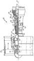
- FIG. 1shows an example gas turbine engine.
- FIG. 1schematically illustrates an example gas turbine engine 20 that includes a fan section 22 , a compressor section 24 , a combustor section 26 , and a turbine section 28 .
- Alternative enginesmight include an augmenter section (not shown) among other systems or features.
- the fan section 22drives air along a bypass flow path B while the compressor section 24 draws air in along a core flow path C where air is compressed and communicated to a combustor section 26 .
- the combustor section 26air is mixed with fuel and ignited to generate a high pressure exhaust gas stream that expands through the turbine section 28 where energy is extracted and utilized to drive the fan section 22 and the compressor section 24 .
- turbofan gas turbine enginedepicts a turbofan gas turbine engine
- the concepts described hereinare not limited to use with turbofans as the teachings may be applied to other types of turbine engines; for example a turbine engine including a three-spool architecture in which three spools concentrically rotate about a common axis and where a low spool enables a low pressure turbine to drive a fan via a gearbox, an intermediate spool that enables an intermediate pressure turbine to drive a first compressor of the compressor section, and a high spool that enables a high pressure turbine to drive a high pressure compressor of the compressor section.
- the example engine 20generally includes a low speed spool 30 and a high speed spool 32 mounted for rotation about an engine central longitudinal axis A relative to an engine static structure 36 via several bearing systems 38 . It should be understood that various bearing systems 38 at various locations may alternatively or additionally be provided.
- the low speed spool 30generally includes an inner shaft 40 that connects a fan 42 and a low pressure (or first) compressor section 44 to a low pressure (or first) turbine section 46 .
- the inner shaft 40drives the fan 42 through a speed change device, such as a geared architecture 48 , to drive the fan 42 at a lower speed than the low speed spool 30 .
- the high speed spool 32includes an outer shaft 50 that interconnects a high pressure (or second) compressor section 52 and a high pressure (or second) turbine section 54 .
- the inner shaft 40 and the outer shaft 50are concentric and rotate via the bearing systems 38 about the engine central longitudinal axis A.
- a combustor 56is arranged between the high pressure compressor 52 and the high pressure turbine 54 .
- the high pressure turbine 54includes at least two stages to provide a double stage high pressure turbine 54 .
- the high pressure turbine 54includes only a single stage.
- a “high pressure” compressor or turbineexperiences a higher pressure than a corresponding “low pressure” compressor or turbine.
- the example low pressure turbine 46has a pressure ratio that is greater than about five (5).
- the pressure ratio of the example low pressure turbine 46is measured prior to an inlet of the low pressure turbine 46 as related to the pressure measured at the outlet of the low pressure turbine 46 prior to an exhaust nozzle.
- a mid-turbine frame 58 of the engine static structure 36is arranged generally between the high pressure turbine 54 and the low pressure turbine 46 .
- the mid-turbine frame 58further supports bearing systems 38 in the turbine section 28 as well as setting airflow entering the low pressure turbine 46 .
- the core airflow Cis compressed by the low pressure compressor 44 then by the high pressure compressor 52 mixed with fuel and ignited in the combustor 56 to produce high speed exhaust gases that are then expanded through the high pressure turbine 54 and low pressure turbine 46 .
- the mid-turbine frame 58includes vanes 60 , which are in the core airflow path and function as an inlet guide vane for the low pressure turbine 46 . Utilizing the vane 60 of the mid-turbine frame 58 as the inlet guide vane for low pressure turbine 46 decreases the length of the low pressure turbine 46 without increasing the axial length of the mid-turbine frame 58 . Reducing or eliminating the number of vanes in the low pressure turbine 46 shortens the axial length of the turbine section 28 . Thus, the compactness of the gas turbine engine 20 is increased and a higher power density may be achieved.
- the disclosed gas turbine engine 20 in one exampleis a high-bypass geared aircraft engine.
- the gas turbine engine 20includes a bypass ratio greater than about six (6), with an example embodiment being greater than about ten (10).
- the example geared architecture 48is an epicyclical gear train, such as a planetary gear system, star gear system or other known gear system, with a gear reduction ratio of greater than about 2.3.
- the gas turbine engine 20includes a bypass ratio greater than about ten (10:1) and the fan diameter is significantly larger than an outer diameter of the low pressure compressor 44 . It should be understood, however, that the above parameters are only exemplary of one embodiment of a gas turbine engine including a geared architecture and that the present disclosure is applicable to other gas turbine engines.
- the fan section 22 of the engine 20is designed for a particular flight condition—typically cruise at about 0.8 Mach and about 35,000 feet.
- TSFCThrust Specific Fuel Consumption
- Low fan pressure ratiois the pressure ratio across the fan blade alone, without a Fan Exit Guide Vane (“FEGV”) system.
- the low fan pressure ratio as disclosed herein according to one non-limiting embodimentis less than about 1.50. In another non-limiting embodiment the low fan pressure ratio is less than about 1.45.
- Low corrected fan tip speedis the actual fan tip speed in ft/sec divided by an industry standard temperature correction of [(Tram °R)/(518.7° R)] 0.5 .
- the “Low corrected fan tip speed,” as disclosed herein according to one non-limiting embodiment,is less than about 1150 ft/second.
- the example gas turbine engineincludes the fan 42 that comprises in one non-limiting embodiment less than about twenty-six (26) fan blades. In another non-limiting embodiment, the fan section 22 includes less than about twenty (20) fan blades. Moreover, in one disclosed embodiment the low pressure turbine 46 includes no more than about six (6) turbine rotors schematically indicated at 34 . In another non-limiting example embodiment the low pressure turbine 46 includes about three (3) turbine rotors. The example low pressure turbine 46 provides the driving power to rotate the fan section 22 and therefore the relationship between the number of turbine rotors 34 in the low pressure turbine 46 and the number of blades in the fan section 22 disclose an example gas turbine engine 20 with increased power transfer efficiency.
- the use of the gear reduction between the low speed spool 30 and the fan 42allows an increase of speed to the low pressure turbine 46 .
- the speed of the low pressure turbine 46 and the low pressure compressor 44has been somewhat limited in that the fan speed cannot be unduly large.
- the maximum fan speedis at its outer tip, and in larger engines, the fan diameter is much larger than it may be in smaller power engines.
- the use of the gear reductionhas freed the designer from limitation on the speeds of the low pressure turbine 46 and the low pressure compressor 44 speeds caused by a desire to not have unduly high fan speeds.
- geared gas turbine enginessuch as the engine 20
- a careful design between the number of vanes and blades in the low pressure turbine 46 , and the mechanical tip rotational Mach number of the low pressure turbine 46can be selected to reduce turbine noise through the use of the mechanism referred to as “cutoff.”
- This “cutoff” mechanismoccurs when the vane-to-blade ratio is selected such that the fundamental blade passage tone is prevented from propagating to the far-field.
- This mechanismhas been used previously in non-geared engines, which have low pressure turbines that operate at low tip Mach numbers, typically no greater than 0.5.
- “cutoff”has not been used in geared engines, such as those described herein, which have low pressure turbines that operate at high tip Mach numbers, typically greater than 0.5.
- the “cutoff” mechanismrequires a larger vane-to-blade ratio than it would on non-geared engines.
- the mechanical tip rotational Mach number, M tipis generally defined as:
- M tip⁇ 720 ⁇ ⁇ c ⁇ DN
- Na rotor rotational speed in revolutions per minute
- cthe local speed of sound in feet per second
- Dthe local tip diameter in inches
- the mechanical tip rotational Mach number for any blade rowmay be calculated in this manner.
- the relationship between the number of vanes and blades in the low pressure turbine 46 , and the mechanical tip rotational Mach number of the low pressure turbine 46may be applicable to three-spool direct drive engines or three-spool engines having a gear reduction as well.
- a ratio of the number of vanes to blades in a stage of the low pressure turbineis greater than or equal to R A .
- a mechanical tip rotational Mach number of the blade of the low pressure turbineis greater than or equal to M A at approach speed.
- R Ais about 1.55 and M A is about 0.5.
- the stage including the vanes and blades greater than or equal to R Acan be any stage of the low pressure turbine 46 .
- the stagemay also be a stage of the high pressure turbine 54 , or, if present, an intermediate pressure turbine.
- R Amay be greater than or equal to 1.55.
- all of the stages in the low pressure turbine 46would include a ratio of vanes to blades that is greater than or equal to R A .
- this disclosuremay also extend to turbines wherein only one of the stages has a ratio of vanes to blades that is greater than or equal to R A .
- This disclosurealso extends to turbines wherein more than one, but less than all, of the stages has a ratio of vanes to blades that is greater than or equal to R A .
- the mechanical tip rotational Mach numberis measured at engine operating conditions corresponding to one or more of the noise certification points defined in Part 36 of the Federal Airworthiness Regulations. More particularly, the rotational speed may be taken as an approach certification point as defined in Part 36 of the Federal Airworthiness Regulations. For purposes of this application and its claims, the term “approach speed” equates to this certification point.
- the disclosed examplesare most applicable to jet engines rated to produce 15,000 pounds (66,723 N) of thrust or more.
Landscapes
- Engineering & Computer Science (AREA)
- Mechanical Engineering (AREA)
- General Engineering & Computer Science (AREA)
- Chemical & Material Sciences (AREA)
- Combustion & Propulsion (AREA)
- Structures Of Non-Positive Displacement Pumps (AREA)
Abstract
Description
wherein N is a rotor rotational speed in revolutions per minute, c is the local speed of sound in feet per second and D is the local tip diameter in inches.
Claims (28)
Priority Applications (10)
| Application Number | Priority Date | Filing Date | Title |
|---|---|---|---|
| US13/970,670US10605172B2 (en) | 2013-03-14 | 2013-08-20 | Low noise turbine for geared gas turbine engine |
| CA2902998ACA2902998C (en) | 2013-03-14 | 2014-03-10 | Low noise turbine for geared gas turbine engine |
| PCT/US2014/022512WO2014159206A1 (en) | 2013-03-14 | 2014-03-10 | Low noise turbine for geared gas turbine engine |
| BR112015022746-5ABR112015022746B1 (en) | 2013-03-14 | 2014-03-10 | GAS TURBINE ENGINE, TURBINE SECTION OF AN ENGINE, AND, METHOD FOR SUPPLYING A PORTION OF A GAS TURBINE ENGINE |
| EP14775864.3AEP2971512B1 (en) | 2013-03-14 | 2014-03-10 | Low noise turbine for geared gas turbine engine |
| US14/606,087US10533447B2 (en) | 2013-03-14 | 2015-01-27 | Low noise turbine for geared gas turbine engine |
| US16/740,611US11143109B2 (en) | 2013-03-14 | 2020-01-13 | Low noise turbine for geared gas turbine engine |
| US16/833,782US11168614B2 (en) | 2013-03-14 | 2020-03-30 | Low noise turbine for geared gas turbine engine |
| US17/488,690US11719161B2 (en) | 2013-03-14 | 2021-09-29 | Low noise turbine for geared gas turbine engine |
| US17/503,814US11560849B2 (en) | 2013-03-14 | 2021-10-18 | Low noise turbine for geared gas turbine engine |
Applications Claiming Priority (2)
| Application Number | Priority Date | Filing Date | Title |
|---|---|---|---|
| US201361781170P | 2013-03-14 | 2013-03-14 | |
| US13/970,670US10605172B2 (en) | 2013-03-14 | 2013-08-20 | Low noise turbine for geared gas turbine engine |
Related Child Applications (3)
| Application Number | Title | Priority Date | Filing Date |
|---|---|---|---|
| US14/606,087Continuation-In-PartUS10533447B2 (en) | 2013-03-14 | 2015-01-27 | Low noise turbine for geared gas turbine engine |
| US14/606,087ContinuationUS10533447B2 (en) | 2013-03-14 | 2015-01-27 | Low noise turbine for geared gas turbine engine |
| US16/833,782ContinuationUS11168614B2 (en) | 2013-03-14 | 2020-03-30 | Low noise turbine for geared gas turbine engine |
Publications (2)
| Publication Number | Publication Date |
|---|---|
| US20140271112A1 US20140271112A1 (en) | 2014-09-18 |
| US10605172B2true US10605172B2 (en) | 2020-03-31 |
Family
ID=51527694
Family Applications (5)
| Application Number | Title | Priority Date | Filing Date |
|---|---|---|---|
| US13/970,670Active2036-11-11US10605172B2 (en) | 2013-03-14 | 2013-08-20 | Low noise turbine for geared gas turbine engine |
| US14/606,087Active2036-06-01US10533447B2 (en) | 2013-03-14 | 2015-01-27 | Low noise turbine for geared gas turbine engine |
| US16/740,611Active2033-11-04US11143109B2 (en) | 2013-03-14 | 2020-01-13 | Low noise turbine for geared gas turbine engine |
| US16/833,782ActiveUS11168614B2 (en) | 2013-03-14 | 2020-03-30 | Low noise turbine for geared gas turbine engine |
| US17/503,814ActiveUS11560849B2 (en) | 2013-03-14 | 2021-10-18 | Low noise turbine for geared gas turbine engine |
Family Applications After (4)
| Application Number | Title | Priority Date | Filing Date |
|---|---|---|---|
| US14/606,087Active2036-06-01US10533447B2 (en) | 2013-03-14 | 2015-01-27 | Low noise turbine for geared gas turbine engine |
| US16/740,611Active2033-11-04US11143109B2 (en) | 2013-03-14 | 2020-01-13 | Low noise turbine for geared gas turbine engine |
| US16/833,782ActiveUS11168614B2 (en) | 2013-03-14 | 2020-03-30 | Low noise turbine for geared gas turbine engine |
| US17/503,814ActiveUS11560849B2 (en) | 2013-03-14 | 2021-10-18 | Low noise turbine for geared gas turbine engine |
Country Status (5)
| Country | Link |
|---|---|
| US (5) | US10605172B2 (en) |
| EP (1) | EP2971512B1 (en) |
| BR (1) | BR112015022746B1 (en) |
| CA (1) | CA2902998C (en) |
| WO (1) | WO2014159206A1 (en) |
Cited By (2)
| Publication number | Priority date | Publication date | Assignee | Title |
|---|---|---|---|---|
| US11168614B2 (en)* | 2013-03-14 | 2021-11-09 | Raytheon Technologies Corporation | Low noise turbine for geared gas turbine engine |
| US11719161B2 (en) | 2013-03-14 | 2023-08-08 | Raytheon Technologies Corporation | Low noise turbine for geared gas turbine engine |
Families Citing this family (10)
| Publication number | Priority date | Publication date | Assignee | Title |
|---|---|---|---|---|
| US9869190B2 (en) | 2014-05-30 | 2018-01-16 | General Electric Company | Variable-pitch rotor with remote counterweights |
| US10072510B2 (en) | 2014-11-21 | 2018-09-11 | General Electric Company | Variable pitch fan for gas turbine engine and method of assembling the same |
| EP3051100A1 (en)* | 2015-01-27 | 2016-08-03 | United Technologies Corporation | Low noise turbine for geared gas turbine engine |
| US10371168B2 (en) | 2015-04-07 | 2019-08-06 | United Technologies Corporation | Modal noise reduction for gas turbine engine |
| US10100653B2 (en) | 2015-10-08 | 2018-10-16 | General Electric Company | Variable pitch fan blade retention system |
| US10710705B2 (en)* | 2017-06-28 | 2020-07-14 | General Electric Company | Open rotor and airfoil therefor |
| US11674435B2 (en) | 2021-06-29 | 2023-06-13 | General Electric Company | Levered counterweight feathering system |
| US11795964B2 (en) | 2021-07-16 | 2023-10-24 | General Electric Company | Levered counterweight feathering system |
| CN116122955B (en)* | 2021-11-15 | 2025-09-23 | 上海汽车集团股份有限公司 | Noise control method for supercharged engine of vehicle |
| US12366176B2 (en) | 2023-08-28 | 2025-07-22 | General Electric Company | Rotor system for a turbine engine |
Citations (32)
| Publication number | Priority date | Publication date | Assignee | Title |
|---|---|---|---|---|
| US3287906A (en) | 1965-07-20 | 1966-11-29 | Gen Motors Corp | Cooled gas turbine vanes |
| GB1072145A (en) | 1965-03-31 | 1967-06-14 | Rolls Royce | Fluid flow machine for exampls a gas turbine engine or lift fan |
| US3659422A (en) | 1966-11-04 | 1972-05-02 | North American Rockwell | Method and apparatus for aircraft propulsion |
| US3754484A (en) | 1971-01-08 | 1973-08-28 | Secr Defence | Gearing |
| US3892358A (en) | 1971-03-17 | 1975-07-01 | Gen Electric | Nozzle seal |
| GB1516041A (en) | 1977-02-14 | 1978-06-28 | Secr Defence | Multistage axial flow compressor stators |
| US4130872A (en) | 1975-10-10 | 1978-12-19 | The United States Of America As Represented By The Secretary Of The Air Force | Method and system of controlling a jet engine for avoiding engine surge |
| GB2041090A (en) | 1979-01-31 | 1980-09-03 | Rolls Royce | By-pass gas turbine engines |
| US5433674A (en) | 1994-04-12 | 1995-07-18 | United Technologies Corporation | Coupling system for a planetary gear train |
| US5447411A (en) | 1993-06-10 | 1995-09-05 | Martin Marietta Corporation | Light weight fan blade containment system |
| US5524847A (en) | 1993-09-07 | 1996-06-11 | United Technologies Corporation | Nacelle and mounting arrangement for an aircraft engine |
| US5778659A (en) | 1994-10-20 | 1998-07-14 | United Technologies Corporation | Variable area fan exhaust nozzle having mechanically separate sleeve and thrust reverser actuation systems |
| US5857836A (en) | 1996-09-10 | 1999-01-12 | Aerodyne Research, Inc. | Evaporatively cooled rotor for a gas turbine engine |
| US5915917A (en) | 1994-12-14 | 1999-06-29 | United Technologies Corporation | Compressor stall and surge control using airflow asymmetry measurement |
| US5975841A (en) | 1997-10-03 | 1999-11-02 | Thermal Corp. | Heat pipe cooling for turbine stators |
| US6223616B1 (en) | 1999-12-22 | 2001-05-01 | United Technologies Corporation | Star gear system with lubrication circuit and lubrication method therefor |
| US6318070B1 (en) | 2000-03-03 | 2001-11-20 | United Technologies Corporation | Variable area nozzle for gas turbine engines driven by shape memory alloy actuators |
| US6814541B2 (en) | 2002-10-07 | 2004-11-09 | General Electric Company | Jet aircraft fan case containment design |
| US7021042B2 (en) | 2002-12-13 | 2006-04-04 | United Technologies Corporation | Geartrain coupling for a turbofan engine |
| WO2007038674A1 (en) | 2005-09-28 | 2007-04-05 | Entrotech Composites, Llc | Braid-reinforced composites and processes for their preparation |
| US20080022691A1 (en) | 2004-04-02 | 2008-01-31 | Mtu Aero Engines Gmbh | Method for Designing a Low-Pressure Turbine of an Aircraft Engine, and Low-Pressure Turbine |
| US7591754B2 (en) | 2006-03-22 | 2009-09-22 | United Technologies Corporation | Epicyclic gear train integral sun gear coupling design |
| US20100148396A1 (en) | 2007-04-17 | 2010-06-17 | General Electric Company | Methods of making articles having toughened and untoughened regions |
| US20100331139A1 (en) | 2009-06-25 | 2010-12-30 | United Technologies Corporation | Epicyclic gear system with superfinished journal bearing |
| US7891943B2 (en) | 2005-11-29 | 2011-02-22 | Ishikawajima-Harima Heavy Industries, Co. Ltd. | Stator cascade of turbo type fluid machine |
| US7926260B2 (en) | 2006-07-05 | 2011-04-19 | United Technologies Corporation | Flexible shaft for gas turbine engine |
| US8205432B2 (en) | 2007-10-03 | 2012-06-26 | United Technologies Corporation | Epicyclic gear train for turbo fan engine |
| US8246292B1 (en) | 2012-01-31 | 2012-08-21 | United Technologies Corporation | Low noise turbine for geared turbofan engine |
| US20130025257A1 (en) | 2011-07-29 | 2013-01-31 | Suciu Gabriel L | Three spool engine bearing configuration |
| US20130259654A1 (en) | 2012-04-02 | 2013-10-03 | Daniel Bernard Kupratis | Geared architecture with speed change device for gas turbine engine |
| US8834099B1 (en) | 2012-09-28 | 2014-09-16 | United Technoloiies Corporation | Low noise compressor rotor for geared turbofan engine |
| US20140271112A1 (en) | 2013-03-14 | 2014-09-18 | United Technologies Corporation | Low noise turbine for geared gas turbine engine |
Family Cites Families (131)
| Publication number | Priority date | Publication date | Assignee | Title |
|---|---|---|---|---|
| US1478551A (en) | 1922-06-02 | 1923-12-25 | Lewis D Castle | Accelerator for automobiles |
| US2258792A (en) | 1941-04-12 | 1941-10-14 | Westinghouse Electric & Mfg Co | Turbine blading |
| US2957655A (en) | 1950-06-01 | 1960-10-25 | Curtiss Wright Corp | Turbine propeller control system |
| US3021731A (en) | 1951-11-10 | 1962-02-20 | Wilhelm G Stoeckicht | Planetary gear transmission |
| US2850226A (en) | 1954-09-28 | 1958-09-02 | Curtiss Wright Corp | Gas turbine engine with air flow modulating means |
| US2936655A (en) | 1955-11-04 | 1960-05-17 | Gen Motors Corp | Self-aligning planetary gearing |
| CH478994A (en) | 1963-05-21 | 1969-09-30 | Jerie Jan | Blade arrangement on axial compressor, blower or fan |
| US3194487A (en) | 1963-06-04 | 1965-07-13 | United Aircraft Corp | Noise abatement method and apparatus |
| US3352178A (en) | 1965-11-15 | 1967-11-14 | Gen Motors Corp | Planetary gearing |
| US3412560A (en) | 1966-08-03 | 1968-11-26 | Gen Motors Corp | Jet propulsion engine with cooled combustion chamber, fuel heater, and induced air-flow |
| US3373928A (en) | 1966-08-29 | 1968-03-19 | Gen Electric | Propulsion fan |
| US3664612A (en) | 1969-12-22 | 1972-05-23 | Boeing Co | Aircraft engine variable highlight inlet |
| US3618699A (en) | 1970-04-27 | 1971-11-09 | Gen Electric | Multiple pure tone noise suppression device for an aircraft gas turbine engine |
| US3765623A (en) | 1971-10-04 | 1973-10-16 | Mc Donnell Douglas Corp | Air inlet |
| US3747343A (en) | 1972-02-10 | 1973-07-24 | United Aircraft Corp | Low noise prop-fan |
| GB1418905A (en) | 1972-05-09 | 1975-12-24 | Rolls Royce | Gas turbine engines |
| US3843277A (en) | 1973-02-14 | 1974-10-22 | Gen Electric | Sound attenuating inlet duct |
| CH557468A (en) | 1973-04-30 | 1974-12-31 | Bbc Brown Boveri & Cie | TURBINE OF AXIAL DESIGN. |
| DE2405890A1 (en) | 1974-02-07 | 1975-08-14 | Siemens Ag | SIDE CHANNEL RING COMPRESSOR |
| US3988889A (en) | 1974-02-25 | 1976-11-02 | General Electric Company | Cowling arrangement for a turbofan engine |
| US3932058A (en) | 1974-06-07 | 1976-01-13 | United Technologies Corporation | Control system for variable pitch fan propulsor |
| US3935558A (en) | 1974-12-11 | 1976-01-27 | United Technologies Corporation | Surge detector for turbine engines |
| US4131387A (en) | 1976-02-27 | 1978-12-26 | General Electric Company | Curved blade turbomachinery noise reduction |
| US4240250A (en) | 1977-12-27 | 1980-12-23 | The Boeing Company | Noise reducing air inlet for gas turbine engines |
| US4284174A (en) | 1979-04-18 | 1981-08-18 | Avco Corporation | Emergency oil/mist system |
| US4220171A (en) | 1979-05-14 | 1980-09-02 | The United States Of America As Represented By The Administrator Of The National Aeronautics And Space Administration | Curved centerline air intake for a gas turbine engine |
| GB2054058B (en) | 1979-06-16 | 1983-04-20 | Rolls Royce | Reducing rotor noise |
| US4289360A (en) | 1979-08-23 | 1981-09-15 | General Electric Company | Bearing damper system |
| DE2940446C2 (en) | 1979-10-05 | 1982-07-08 | B. Braun Melsungen Ag, 3508 Melsungen | Cultivation of animal cells in suspension and monolayer cultures in fermentation vessels |
| US4478551A (en) | 1981-12-08 | 1984-10-23 | United Technologies Corporation | Turbine exhaust case design |
| US4968216A (en) | 1984-10-12 | 1990-11-06 | The Boeing Company | Two-stage fluid driven turbine |
| US4883240A (en) | 1985-08-09 | 1989-11-28 | General Electric Company | Aircraft propeller noise reduction |
| US4722357A (en) | 1986-04-11 | 1988-02-02 | United Technologies Corporation | Gas turbine engine nacelle |
| US4696156A (en) | 1986-06-03 | 1987-09-29 | United Technologies Corporation | Fuel and oil heat management system for a gas turbine engine |
| US5022824A (en)* | 1988-10-07 | 1991-06-11 | United Technologies Corporation | Pinned airfoil propeller blade |
| US4979362A (en) | 1989-05-17 | 1990-12-25 | Sundstrand Corporation | Aircraft engine starting and emergency power generating system |
| US5141182A (en) | 1990-06-01 | 1992-08-25 | General Electric Company | Gas turbine engine fan duct base pressure drag reduction |
| US5058617A (en) | 1990-07-23 | 1991-10-22 | General Electric Company | Nacelle inlet for an aircraft gas turbine engine |
| US5152668A (en) | 1990-07-23 | 1992-10-06 | General Electric Company | Pitch change mechanism for prop fans |
| US5174716A (en) | 1990-07-23 | 1992-12-29 | General Electric Company | Pitch change mechanism |
| US5190441A (en) | 1990-08-13 | 1993-03-02 | General Electric Company | Noise reduction in aircraft propellers |
| US5141400A (en) | 1991-01-25 | 1992-08-25 | General Electric Company | Wide chord fan blade |
| US5102379A (en) | 1991-03-25 | 1992-04-07 | United Technologies Corporation | Journal bearing arrangement |
| US5197855A (en) | 1991-07-01 | 1993-03-30 | United Technologies Corporation | Engine exhaust/blade interaction noise suppression |
| US5144182A (en) | 1991-09-04 | 1992-09-01 | Onan Corporation | Skewed rotor assembly |
| US5169288A (en) | 1991-09-06 | 1992-12-08 | General Electric Company | Low noise fan assembly |
| US5317877A (en) | 1992-08-03 | 1994-06-07 | General Electric Company | Intercooled turbine blade cooling air feed system |
| US5466198A (en) | 1993-06-11 | 1995-11-14 | United Technologies Corporation | Geared drive system for a bladed propulsor |
| US5361580A (en) | 1993-06-18 | 1994-11-08 | General Electric Company | Gas turbine engine rotor support system |
| RU2082824C1 (en) | 1994-03-10 | 1997-06-27 | Московский государственный авиационный институт (технический университет) | Method of protection of heat-resistant material from effect of high-rapid gaseous flow of corrosive media (variants) |
| US5486091A (en) | 1994-04-19 | 1996-01-23 | United Technologies Corporation | Gas turbine airfoil clocking |
| JPH08109834A (en) | 1994-10-13 | 1996-04-30 | Ishikawajima Harima Heavy Ind Co Ltd | Resin parts for jet engine |
| JP2969075B2 (en) | 1996-02-26 | 1999-11-02 | ジャパンゴアテックス株式会社 | Degassing device |
| US5634767A (en) | 1996-03-29 | 1997-06-03 | General Electric Company | Turbine frame having spindle mounted liner |
| JP3621216B2 (en) | 1996-12-05 | 2005-02-16 | 株式会社東芝 | Turbine nozzle |
| US5985470A (en) | 1998-03-16 | 1999-11-16 | General Electric Company | Thermal/environmental barrier coating system for silicon-based materials |
| AU2341200A (en) | 1998-08-17 | 2000-04-17 | Ramgen Power Systems, Inc. | Ramjet engine with axial air supply fan |
| CZ298956B6 (en) | 1998-12-09 | 2008-03-19 | Wind power installation rotor blade and wind power installation per se | |
| US6195983B1 (en) | 1999-02-12 | 2001-03-06 | General Electric Company | Leaned and swept fan outlet guide vanes |
| US6517341B1 (en) | 1999-02-26 | 2003-02-11 | General Electric Company | Method to prevent recession loss of silica and silicon-containing materials in combustion gas environments |
| US6410148B1 (en) | 1999-04-15 | 2002-06-25 | General Electric Co. | Silicon based substrate with environmental/ thermal barrier layer |
| US6260794B1 (en) | 1999-05-05 | 2001-07-17 | General Electric Company | Dolphin cascade vane |
| US6315815B1 (en) | 1999-12-16 | 2001-11-13 | United Technologies Corporation | Membrane based fuel deoxygenator |
| US6444335B1 (en) | 2000-04-06 | 2002-09-03 | General Electric Company | Thermal/environmental barrier coating for silicon-containing materials |
| EP1317608A4 (en) | 2000-09-05 | 2004-12-15 | Sudarshan Paul Dev | COMPACT GAS TURBINE |
| US6575406B2 (en) | 2001-01-19 | 2003-06-10 | The Boeing Company | Integrated and/or modular high-speed aircraft |
| AUPR728501A0 (en) | 2001-08-27 | 2001-09-20 | Johns, Bradley Charles | Apparatus for dispensing a vapour into an air flow |
| US6554564B1 (en) | 2001-11-14 | 2003-04-29 | United Technologies Corporation | Reduced noise fan exit guide vane configuration for turbofan engines |
| US6708482B2 (en) | 2001-11-29 | 2004-03-23 | General Electric Company | Aircraft engine with inter-turbine engine frame |
| GB2383380B (en)* | 2001-12-19 | 2005-05-25 | Rolls Royce Plc | Rotor assemblies for gas turbine engines |
| US6732502B2 (en) | 2002-03-01 | 2004-05-11 | General Electric Company | Counter rotating aircraft gas turbine engine with high overall pressure ratio compressor |
| US6607165B1 (en) | 2002-06-28 | 2003-08-19 | General Electric Company | Aircraft engine mount with single thrust link |
| US6964155B2 (en) | 2002-12-30 | 2005-11-15 | United Technologies Corporation | Turbofan engine comprising an spicyclic transmission having bearing journals |
| US6709492B1 (en) | 2003-04-04 | 2004-03-23 | United Technologies Corporation | Planar membrane deoxygenator |
| US6943699B2 (en) | 2003-07-23 | 2005-09-13 | Harris Corporation | Wireless engine monitoring system |
| US7328580B2 (en) | 2004-06-23 | 2008-02-12 | General Electric Company | Chevron film cooled wall |
| US7546742B2 (en) | 2004-12-08 | 2009-06-16 | General Electric Company | Gas turbine engine assembly and method of assembling same |
| GB0502324D0 (en)* | 2005-03-14 | 2005-03-16 | Rolls Royce Plc | A multi-shaft arrangement for a turbine engine |
| GB0506685D0 (en) | 2005-04-01 | 2005-05-11 | Hopkins David R | A design to increase and smoothly improve the throughput of fluid (air or gas) through the inlet fan (or fans) of an aero-engine system |
| US7374403B2 (en) | 2005-04-07 | 2008-05-20 | General Electric Company | Low solidity turbofan |
| US7594388B2 (en) | 2005-06-06 | 2009-09-29 | General Electric Company | Counterrotating turbofan engine |
| US7387489B2 (en)* | 2005-10-17 | 2008-06-17 | Honeywell International Inc. | Bleed valve outlet flow deflector |
| US7752836B2 (en) | 2005-10-19 | 2010-07-13 | General Electric Company | Gas turbine assembly and methods of assembling same |
| US7526913B2 (en) | 2005-10-19 | 2009-05-05 | General Electric Company | Gas turbine engine assembly and methods of assembling same |
| BE1017135A3 (en) | 2006-05-11 | 2008-03-04 | Hansen Transmissions Int | A GEARBOX FOR A WIND TURBINE. |
| US20080003096A1 (en) | 2006-06-29 | 2008-01-03 | United Technologies Corporation | High coverage cooling hole shape |
| JP4911344B2 (en) | 2006-07-04 | 2012-04-04 | 株式会社Ihi | Turbofan engine |
| US8585538B2 (en) | 2006-07-05 | 2013-11-19 | United Technologies Corporation | Coupling system for a star gear train in a gas turbine engine |
| US7694505B2 (en) | 2006-07-31 | 2010-04-13 | General Electric Company | Gas turbine engine assembly and method of assembling same |
| US7632064B2 (en) | 2006-09-01 | 2009-12-15 | United Technologies Corporation | Variable geometry guide vane for a gas turbine engine |
| US20090260345A1 (en) | 2006-10-12 | 2009-10-22 | Zaffir Chaudhry | Fan variable area nozzle with adaptive structure |
| US8302405B2 (en)* | 2006-10-13 | 2012-11-06 | Rolls-Royce Power Engineering Plc | Dynamic control of a gas turbine engine compressor during rapid transients |
| US7662059B2 (en) | 2006-10-18 | 2010-02-16 | United Technologies Corporation | Lubrication of windmilling journal bearings |
| US7841165B2 (en) | 2006-10-31 | 2010-11-30 | General Electric Company | Gas turbine engine assembly and methods of assembling same |
| US7921634B2 (en) | 2006-10-31 | 2011-04-12 | General Electric Company | Turbofan engine assembly and method of assembling same |
| US7966806B2 (en) | 2006-10-31 | 2011-06-28 | General Electric Company | Turbofan engine assembly and method of assembling same |
| US8020665B2 (en) | 2006-11-22 | 2011-09-20 | United Technologies Corporation | Lubrication system with extended emergency operability |
| US7721549B2 (en) | 2007-02-08 | 2010-05-25 | United Technologies Corporation | Fan variable area nozzle for a gas turbine engine fan nacelle with cam drive ring actuation system |
| US7950237B2 (en) | 2007-06-25 | 2011-05-31 | United Technologies Corporation | Managing spool bearing load using variable area flow nozzle |
| US9359960B2 (en)* | 2007-06-28 | 2016-06-07 | United Technologies Corporation | Gas turbines with multiple gas flow paths |
| US20120124964A1 (en) | 2007-07-27 | 2012-05-24 | Hasel Karl L | Gas turbine engine with improved fuel efficiency |
| US8256707B2 (en) | 2007-08-01 | 2012-09-04 | United Technologies Corporation | Engine mounting configuration for a turbofan gas turbine engine |
| US7984607B2 (en) | 2007-09-06 | 2011-07-26 | United Technologies Corp. | Gas turbine engine systems and related methods involving vane-blade count ratios greater than unity |
| US10151248B2 (en) | 2007-10-03 | 2018-12-11 | United Technologies Corporation | Dual fan gas turbine engine and gear train |
| US8167540B2 (en) | 2008-01-30 | 2012-05-01 | Hamilton Sundstrand Corporation | System for reducing compressor noise |
| US8141366B2 (en) | 2008-08-19 | 2012-03-27 | United Technologies Corporation | Gas turbine engine with variable area fan nozzle |
| US8807477B2 (en) | 2008-06-02 | 2014-08-19 | United Technologies Corporation | Gas turbine engine compressor arrangement |
| US8128021B2 (en) | 2008-06-02 | 2012-03-06 | United Technologies Corporation | Engine mount system for a turbofan gas turbine engine |
| US20090301055A1 (en) | 2008-06-04 | 2009-12-10 | United Technologies Corp. | Gas Turbine Engine Systems and Methods Involving Vibration Monitoring |
| US7997868B1 (en) | 2008-11-18 | 2011-08-16 | Florida Turbine Technologies, Inc. | Film cooling hole for turbine airfoil |
| US8881534B2 (en)* | 2008-12-29 | 2014-11-11 | Rolls-Royce Corporation | Gas turbine engine shaft coupler |
| US20100192595A1 (en) | 2009-01-30 | 2010-08-05 | Robert Joseph Orlando | Gas turbine engine assembly and methods of assembling same |
| US8307626B2 (en) | 2009-02-26 | 2012-11-13 | United Technologies Corporation | Auxiliary pump system for fan drive gear system |
| US8181441B2 (en) | 2009-02-27 | 2012-05-22 | United Technologies Corporation | Controlled fan stream flow bypass |
| US8176725B2 (en) | 2009-09-09 | 2012-05-15 | United Technologies Corporation | Reversed-flow core for a turbofan with a fan drive gear system |
| US9170616B2 (en) | 2009-12-31 | 2015-10-27 | Intel Corporation | Quiet system cooling using coupled optimization between integrated micro porous absorbers and rotors |
| US8752394B2 (en) | 2010-03-15 | 2014-06-17 | Rolls-Royce Corporation | Determining fan parameters through pressure monitoring |
| US8905713B2 (en) | 2010-05-28 | 2014-12-09 | General Electric Company | Articles which include chevron film cooling holes, and related processes |
| DE102010023703A1 (en) | 2010-06-14 | 2011-12-15 | Rolls-Royce Deutschland Ltd & Co Kg | Turbomachine with noise reduction |
| US7976283B2 (en) | 2010-11-10 | 2011-07-12 | General Electric Company | Noise reducer for rotor blade in wind turbine |
| US9909505B2 (en) | 2011-07-05 | 2018-03-06 | United Technologies Corporation | Efficient, low pressure ratio propulsor for gas turbine engines |
| US20130186058A1 (en) | 2012-01-24 | 2013-07-25 | William G. Sheridan | Geared turbomachine fan and compressor rotation |
| US9169781B2 (en) | 2012-01-31 | 2015-10-27 | United Technologies Corporation | Turbine engine gearbox |
| US8632301B2 (en) | 2012-01-31 | 2014-01-21 | United Technologies Corporation | Low noise compressor rotor for geared turbofan engine |
| WO2013122713A2 (en) | 2012-01-31 | 2013-08-22 | United Technologies Corporation | Low noise compressor rotor for geared turbofan engine |
| US8714913B2 (en) | 2012-01-31 | 2014-05-06 | United Technologies Corporation | Low noise compressor rotor for geared turbofan engine |
| US10036351B2 (en) | 2012-04-02 | 2018-07-31 | United Technologies Corporation | Geared turbofan with three co-rotating turbines |
| US20130318998A1 (en) | 2012-05-31 | 2013-12-05 | Frederick M. Schwarz | Geared turbofan with three turbines with high speed fan drive turbine |
| EP3557214B1 (en) | 2018-04-20 | 2022-08-24 | Hamilton Sundstrand Corporation | A blade for a propeller with blade composite structure and an extrinsic fabry-perot interferometric sensor embedded in the blade composite structure |
| JP7104247B2 (en) | 2019-07-09 | 2022-07-20 | グーグル エルエルシー | On-device speech synthesis of text segments for training on-device speech recognition models |
| US20210062661A1 (en) | 2019-08-28 | 2021-03-04 | Rotating Composite Technologies, Llc | Composite propulsor blade retention structure and method for constructing same |
- 2013
- 2013-08-20USUS13/970,670patent/US10605172B2/enactiveActive
- 2014
- 2014-03-10BRBR112015022746-5Apatent/BR112015022746B1/enactiveIP Right Grant
- 2014-03-10EPEP14775864.3Apatent/EP2971512B1/enactiveActive
- 2014-03-10CACA2902998Apatent/CA2902998C/enactiveActive
- 2014-03-10WOPCT/US2014/022512patent/WO2014159206A1/enactiveApplication Filing
- 2015
- 2015-01-27USUS14/606,087patent/US10533447B2/enactiveActive
- 2020
- 2020-01-13USUS16/740,611patent/US11143109B2/enactiveActive
- 2020-03-30USUS16/833,782patent/US11168614B2/enactiveActive
- 2021
- 2021-10-18USUS17/503,814patent/US11560849B2/enactiveActive
Patent Citations (34)
| Publication number | Priority date | Publication date | Assignee | Title |
|---|---|---|---|---|
| GB1072145A (en) | 1965-03-31 | 1967-06-14 | Rolls Royce | Fluid flow machine for exampls a gas turbine engine or lift fan |
| US3287906A (en) | 1965-07-20 | 1966-11-29 | Gen Motors Corp | Cooled gas turbine vanes |
| US3659422A (en) | 1966-11-04 | 1972-05-02 | North American Rockwell | Method and apparatus for aircraft propulsion |
| US3754484A (en) | 1971-01-08 | 1973-08-28 | Secr Defence | Gearing |
| US3892358A (en) | 1971-03-17 | 1975-07-01 | Gen Electric | Nozzle seal |
| US4130872A (en) | 1975-10-10 | 1978-12-19 | The United States Of America As Represented By The Secretary Of The Air Force | Method and system of controlling a jet engine for avoiding engine surge |
| GB1516041A (en) | 1977-02-14 | 1978-06-28 | Secr Defence | Multistage axial flow compressor stators |
| GB2041090A (en) | 1979-01-31 | 1980-09-03 | Rolls Royce | By-pass gas turbine engines |
| US5447411A (en) | 1993-06-10 | 1995-09-05 | Martin Marietta Corporation | Light weight fan blade containment system |
| US5524847A (en) | 1993-09-07 | 1996-06-11 | United Technologies Corporation | Nacelle and mounting arrangement for an aircraft engine |
| US5433674A (en) | 1994-04-12 | 1995-07-18 | United Technologies Corporation | Coupling system for a planetary gear train |
| US5778659A (en) | 1994-10-20 | 1998-07-14 | United Technologies Corporation | Variable area fan exhaust nozzle having mechanically separate sleeve and thrust reverser actuation systems |
| US5915917A (en) | 1994-12-14 | 1999-06-29 | United Technologies Corporation | Compressor stall and surge control using airflow asymmetry measurement |
| US5857836A (en) | 1996-09-10 | 1999-01-12 | Aerodyne Research, Inc. | Evaporatively cooled rotor for a gas turbine engine |
| US5975841A (en) | 1997-10-03 | 1999-11-02 | Thermal Corp. | Heat pipe cooling for turbine stators |
| US6223616B1 (en) | 1999-12-22 | 2001-05-01 | United Technologies Corporation | Star gear system with lubrication circuit and lubrication method therefor |
| US6318070B1 (en) | 2000-03-03 | 2001-11-20 | United Technologies Corporation | Variable area nozzle for gas turbine engines driven by shape memory alloy actuators |
| US6814541B2 (en) | 2002-10-07 | 2004-11-09 | General Electric Company | Jet aircraft fan case containment design |
| US7021042B2 (en) | 2002-12-13 | 2006-04-04 | United Technologies Corporation | Geartrain coupling for a turbofan engine |
| US20080022691A1 (en) | 2004-04-02 | 2008-01-31 | Mtu Aero Engines Gmbh | Method for Designing a Low-Pressure Turbine of an Aircraft Engine, and Low-Pressure Turbine |
| US7806651B2 (en) | 2004-04-02 | 2010-10-05 | Mtu Aero Engines Gmbh | Method for designing a low-pressure turbine of an aircraft engine, and low-pressure turbine |
| WO2007038674A1 (en) | 2005-09-28 | 2007-04-05 | Entrotech Composites, Llc | Braid-reinforced composites and processes for their preparation |
| US7891943B2 (en) | 2005-11-29 | 2011-02-22 | Ishikawajima-Harima Heavy Industries, Co. Ltd. | Stator cascade of turbo type fluid machine |
| US7591754B2 (en) | 2006-03-22 | 2009-09-22 | United Technologies Corporation | Epicyclic gear train integral sun gear coupling design |
| US7824305B2 (en) | 2006-03-22 | 2010-11-02 | United Technologies Corporation | Integral sun gear coupling |
| US7926260B2 (en) | 2006-07-05 | 2011-04-19 | United Technologies Corporation | Flexible shaft for gas turbine engine |
| US20100148396A1 (en) | 2007-04-17 | 2010-06-17 | General Electric Company | Methods of making articles having toughened and untoughened regions |
| US8205432B2 (en) | 2007-10-03 | 2012-06-26 | United Technologies Corporation | Epicyclic gear train for turbo fan engine |
| US20100331139A1 (en) | 2009-06-25 | 2010-12-30 | United Technologies Corporation | Epicyclic gear system with superfinished journal bearing |
| US20130025257A1 (en) | 2011-07-29 | 2013-01-31 | Suciu Gabriel L | Three spool engine bearing configuration |
| US8246292B1 (en) | 2012-01-31 | 2012-08-21 | United Technologies Corporation | Low noise turbine for geared turbofan engine |
| US20130259654A1 (en) | 2012-04-02 | 2013-10-03 | Daniel Bernard Kupratis | Geared architecture with speed change device for gas turbine engine |
| US8834099B1 (en) | 2012-09-28 | 2014-09-16 | United Technoloiies Corporation | Low noise compressor rotor for geared turbofan engine |
| US20140271112A1 (en) | 2013-03-14 | 2014-09-18 | United Technologies Corporation | Low noise turbine for geared gas turbine engine |
Non-Patent Citations (82)
| Title |
|---|
| "Civil Turbojet/Turbofan Specifications", Jet Engine Specification Database (Apr. 3, 2005). |
| Agarwal, B.D and Broutman, L.J. (1990). Analysis and performance of fiber composites, 2nd Edition. John Wiley & Sons, Inc. New York: New York. |
| Avco Lycoming Divison. ALF 502L Maintenance Manual. Apr. 1981. pp. 1-118. |
| Aviadvigatel D-110. Jane's Aero-engines, Aero-engines—Turbofan. Jun. 1, 2010. |
| Brennan, P.J. and Kroliczek, E.J. (1979). Heat pipe design handbook. Prepared for National Aeronautics and Space Administration by B & K Engineering, Inc. Jun. 1979. |
| Brines, G.L. (1990). The turbofan of tomorrow. Mechanical Engineering: The Journal of the American Society of Mechanical Engineers,108(8), 65-67. |
| C RIEGLER, BICHLMAIER C: "THE GEARED TURBOFAN TECHNOLOGY – OPPORTUNITIES, CHALLENGES AND READINESS STATUS", PROCEEDINGS CEAS 2007, 11 September 2007 (2007-09-11), XP055195802 |
| Carney, K., Pereira, M. Revilock, and Matheny, P. Jet engine fan blade containment using two alternate geometries. 4th European LS-DYNA Users Conference. |
| Conference on Engineering and Physics: Synergy for Success 2006. Journal of Physics: Conference Series vol. 105. London, UK. Oct. 5, 2006. |
| Cusick, M. (1981). Avco Lycoming's ALF 502 high bypass fan engine. Society of Automotive Engineers, inc. Business Aircraft Meeting & Exposition. Wichita, Kansas. Apr. 7-10, 1981. |
| Cusick, M. (1981). Avco Lycoming's ALF 502 high bypass fan engine. Society of Automotive Engineers, inc. Business Aircraft Meeting & Exposition. Wichita, Kansas. Apr. 7-10, 1981. pp. 1-9. |
| Dassault Falcon 900EX Easy Systems Summary. Retrieved from: http://www.smartcockpit.comidocs/F900EX-Engines.pdf pp. 1-31. |
| Dickey, T.A and Dobak, E.R. (1972). The evolution and development status of ALF 502 turbofan engine. National Aerospace Engineering and Manufacturing Meeting. San Diego, California. Oct. 2-5, 1972. |
| Dickey, T.A. and Dobak, E.R. (1972). The evolution and development status of ALF 502 turbofan engine. National Aerospace Engineering and Manufacturing Meeting. San Diego, California. Oct. 2-5, 1972. pp. 1-12. |
| European Search Report for Application No. 14775864.3 dated Sep. 29, 2016. |
| Extended European Search Report for Application No. 16152992.0 dated Jun. 20, 2016. |
| Faghri, A. (1995). Heat pipe and science technology. Washington, D.C: Taylor & Francis. |
| File History for U.S. Appl. No. 12/131,876. |
| Fledderjohn, K.R. (1983). The TFE731-5: Evolution of a decade of business jet service. SAE Technical Paper Series. Business Aircraft Meeting & Exposition. Wichita, Kansas. Apr. 12-15, 1983. |
| Garret TFE731 Turbofan Engine (CAT C). Chapter 79: Lubrciation System. TTFE731 Issue 2. 2010. pp. 1-24. |
| Gliebe, Philip R. et al, Ultra-High Bypass Engine Aeroacoustic Study, NASA CR-2003-212525, Oct. 1, 2003, XP55277347, Retrieved from the Internet on Jun. 2, 2016 from URL:http://ntrs.nasa.gov/archive/nasa/casi.ntrs.nasa.gov/20040000741.pdf. |
| Grady, J.E., Weir, D.S., Lamoureux, M.C., and Martinez, M.M. (2007). Engine noise research in NASA's quiet aircraft technology project. Papers from the International Symposium on Air Breathing Engines (ISABE). 2007. |
| Griffiths, B. (2005). Composite fan blade containment case. Modern Machine Shop. Retrieved from: http://www.mmsonline.com/articles/composite-fan-blade-containment-case. |
| Gunston, B. (Ed.) (2000). Jane's aero-engines, Issue seven. Coulsdon, Surrey, UK: Jane's Information Group Limited. |
| Guynn, M. D., Berton, J.J., Fisher, K. L., Haller, W.J., Tong, M. T., and Thurman, Dr. (2011). Refined exploration of turbofan design options for an advanced single-aisle transport. NASA/TM-2011-216883. |
| Hall, C.A. and Crichton, D. (2007). Engine design studies for a silent aircraft. Journal of Turbomachinery, 129, 479-487. |
| Haque, A. and Shamsuzzoha, M., Hussain, F., and Dean, D. (2003). S20-glass/epoxy polymer nanocomposites: Manufacturing, structures, thermal and mechanical properties. Journal of Composite Materials, 37(20), 1821-1837. |
| Hendricks, E.S. and Tong, M.T. (2012). Performance and weight estimates for an advanced open rotor engine. NASA/TM-2012-217710. |
| Hess, C. (1998). Pratt & Whitney develops geared turbofan. Flug Revue 43(7). Oct. 1998. |
| Honeywell LF502. Jane's Aero-engines, Aero-engines—Turbofan. Aug. 17, 2016. |
| Honeywell LF502. Jane's Aero-engines, Aero-engines—Turbofan. Feb. 9, 2012. |
| Honeywell LF507. Jane's Aero-engines, Aero-engines—Turbofan. Feb. 9, 2012. |
| Honeywell TFE731 Pilot Tips. pp. 1-143. |
| Honeywell TFE731. Jane's Aero-engines, Aero-engines—Turbofan. Jul. 18, 2012. |
| Honeywell TFE731-5AR to -5BR Engine Conversion Program. Sep. 2005. pp. 1-4. |
| Horikoshi, S. and Serpone, N. (2013). Introduction to nanoparticles. Microwaves in nanoparticle synthesis. Wiley-VCH Verlag GmbH & Co. KGaA. |
| Hughes, C. (2010). Geared turbofan technology. NASA Environmentally Responsible Aviation Project. Green Aviation Summit. NASA Ames Research Center. Sep. 8-9, 2010. |
| International Preliminary Report on Patentability for PCT Application No. PCT/US2014/022512, dated Sep. 24, 2015. |
| International Search Report and Written Opinion for PCT Application No. PCT/US2014/022512, dated Jul. 28, 2014. |
| Ivchenko-Progress Al-727M. Jane's Aero-engines, Aero-engines—Turbofan. Nov. 27, 2011. |
| Ivchenko-Progress D-436. Jane's Aero-engines, Aero-engines—Turbofan. Feb. 8, 2012. |
| Ivchenko-Progress D-727. Jane's Aero-engines, Aero-engines—Turbofan. Feb. 7, 2007. |
| Kandebo, S.W. (1993). Geared-turbofan engine design targets cost, complexity. Aviation Week & Space Technology, 148(8), p. 32. |
| Kerrebrock, J.L. (1977). Aircraft engines and gas turbines. Cambridge, MA: The MIT Press. |
| Knip, Jr., G. (1987). Analysis of an advanced technology subsonic turbofan incorporating revolutionary materials. NASA Technical Memorandum. May 1987. |
| Kojima, Y., Usuki, A. Kawasumi, M., Okada, A., Fukushim, Y., Kurauchi, T., and Kamigaito, O. (1992). Mechanical properties of nylon 6-clay hybrid. Journal of Materials Research, 8(5), 1185-1189. |
| Kollar, L.P. and Springer, G.S. (2003). Mechanics of composite structures. Cambridge, UK: Cambridge University Press. |
| Kurzke, J. (2009). Fundamental differences between conventional and geared turbofans. Proceedings of ASME Turbo Expo: Power for Land, Sea, and Air. 2009, Orlando, Florida. |
| Langston, L. and Faghri, A. Heat pipe turbine vane cooling. Prepared for Advanced Turbine Systems Annual Program Review. Morgantown, West Virginia. Oct. 17-19, 1995. |
| Lau K., Gu, C. and Hui, D. (2005). A critical review on nanotube and nanotube/nanoclay related polymer composite materials. Composites: Part B 37(2006) 425-436. |
| Lynwander, P. (1983). Gear drive systems: Design and application. New York, New York: Marcel Dekker, Inc. |
| Mark H. Waters and Edward T., NASA Technical Memorandum: Analysis of Turbofan Propulsion System Weight and Dimensions, 1977.* |
| Mattingly, J.D. (1996). Elements of gas turbine propulsion. New York, New York: McGraw-Hill, Inc. |
| Merriam-Webster's collegiate dictionary, 10th Ed. (2001). p. 1125-1126. |
| Merriam-Webster's collegiate dictionary, 11th Ed. (2009). p. 824. |
| Munt, R. (1981). Aircraft technology assessment: Progress in low emissions engine. Technical Report. May 1981. pp. 1-171. |
| Nanocor Technical Data for Epoxy Nanocomposites using Nanomer 1.30E Nanoclay. Nnacor, Inc. |
| NASA Conference Publication. Quiet, powered-lift propulsion. Cleveland, Ohio. Nov. 14-15, 1978. |
| Oates, G.C. (Ed). (1989). Aircraft propulsion systems and technology and design. Washington, D.C.: American Institute of Aeronautics, Inc. |
| Pyrograf-III Carbon Nanofiber. Product guide. Retrieved from: http://pyrografproducts.com/Merchant5/merchant.mvc?Screen=cp_nanofiber. |
| Ramsden, J.M. (Ed). (1978). The new European airliner. Flight International, 113(3590). Jan. 7, 1978. |
| Ratna, D. (2009). Handbook of thermoset resins. Shawbury, UK: iSmithers. |
| Rauch, D. (1972). Design study of an air pump and integral lift engine ALF-504 using the Lycoming 502 core. Prepare for NASA. Jul. 1972. pp. 1-182. |
| Riegler, C., et al, The Geared Turbofan Technology-Opportunities, Challenges and Readiness Status, Proceedings CEAS 2007, Sep. 11, 2007, XP055195802. |
| Rolls-Royce M45H. Jane's Aero-engines, Aero-engines—Turbofan. Feb. 24, 2010. |
| Roux, Elodie, Turbofan and Turbojet Engines: Database Handbook, copyright: 2007, p. 1-595, Editions Elodie Roux, France, printed by lulu.com. |
| Shorter Oxford English dictionary, 6th Edition. (2007). vol. 2, N-Z. p. 1888. |
| Silverstein, C.C., Gottschlich, J.M., and Meininger, M. The feasibility of heat pipe turbine vane cooling. Presented at the International Gas Turbine and Aeroengine Congress and Exposition, The Hague, Netherlands. Jun. 13-16, 1994. |
| Sweetman, B. and Sutton, O. (1998). Pratt & Whitney's surprise leap. Interavia Business & Technology, 53.621, p. 25. |
| Trembley, Jr., H.F. (1977). Determination of effects of ambient conditions on aircraft engine emissions. Prepared for Environmental Protection Agency. Ann Arbor, Michigan. Sep. 1977 pp. 1-256. |
| Turbomeca Aubisque. Jane's Aero-engines, Aero-engines—Turbofan. Nov. 2, 2009. |
| Type Certificate Data Sheet No. E6NE. Department of Transportation Federal Aviation Administration. Jun. 7, 2002. pp. 1-10. |
| U.S. Appl. No. 12/622,458, filed Nov. 20, 2009. |
| U.S. Appl. No. 13/590,328, filed Sep. 28, 2012. |
| U.S. Appl. No. 13/630,276, filed Aug. 21, 2012. |
| Waters, M.H. and Schairer, E.T. (1977). Analysis of turbofan propulsion system weight and dimensions. NASA Technical Memorandum. Jan. 1977. pp. 1-65. |
| Waters, Mark H., et al, Analysis of Turbofan Propulsion System Weight and Dimensions, NASA TM X-73,199, Jan. 31, 1977, pp. 1-65, XP55306421, Retrieved from the Internet on Sep. 29, 2016 at URL:http://ntrs.nasa.gov/archive/nasa/casi.ntrs.nasa.gov/19770012125.pdf. |
| Wendus, B.E., Stark, D.F., Holler, R.P., and Funkhouser, M.E. (2003). Follow-on technology requirement study for advanced subsonic transport. NASA/CR-2003-212467. |
| Whitaker, R. (1982). ALF 502: plugging the turbofan gap. Flight International, p. 237-241, Jan. 30, 1982. |
| Willis, W.S. (1979). Quiet clean short-haul experimental engine (QCSEE) final report NASA/CR-159473. |
| Xie, M. (2008). Intelligent engine systems: Smart case system. NASA/CR-2008-215233. |
| Zalud, T. (1998). Gears put a new spin on turbofan performance. Machine Design, 70(20), p. 104. |
Cited By (3)
| Publication number | Priority date | Publication date | Assignee | Title |
|---|---|---|---|---|
| US11168614B2 (en)* | 2013-03-14 | 2021-11-09 | Raytheon Technologies Corporation | Low noise turbine for geared gas turbine engine |
| US11560849B2 (en) | 2013-03-14 | 2023-01-24 | Raytheon Technologies Corporation | Low noise turbine for geared gas turbine engine |
| US11719161B2 (en) | 2013-03-14 | 2023-08-08 | Raytheon Technologies Corporation | Low noise turbine for geared gas turbine engine |
Also Published As
| Publication number | Publication date |
|---|---|
| EP2971512A1 (en) | 2016-01-20 |
| US20200291859A1 (en) | 2020-09-17 |
| US20200400075A1 (en) | 2020-12-24 |
| BR112015022746B1 (en) | 2022-01-11 |
| US11560849B2 (en) | 2023-01-24 |
| WO2014159206A1 (en) | 2014-10-02 |
| EP2971512A4 (en) | 2016-11-09 |
| US20220220899A1 (en) | 2022-07-14 |
| BR112015022746A2 (en) | 2017-07-18 |
| CA2902998A1 (en) | 2014-10-02 |
| CA2902998C (en) | 2018-05-29 |
| US11143109B2 (en) | 2021-10-12 |
| US20140271112A1 (en) | 2014-09-18 |
| EP2971512B1 (en) | 2020-12-02 |
| US10533447B2 (en) | 2020-01-14 |
| US11168614B2 (en) | 2021-11-09 |
| US20160177774A1 (en) | 2016-06-23 |
Similar Documents
| Publication | Publication Date | Title |
|---|---|---|
| US11560849B2 (en) | Low noise turbine for geared gas turbine engine | |
| US8246292B1 (en) | Low noise turbine for geared turbofan engine | |
| US20200174032A1 (en) | Low noise compressor and turbine for geared turbofan engine | |
| US20140318147A1 (en) | Low noise compressor rotor for geared turbofan engine | |
| US20200173370A1 (en) | Low noise compressor rotor for geared turbofan engine | |
| US20140182309A1 (en) | Geared gas turbine engine exhaust nozzle with chevrons | |
| US10337407B2 (en) | Low noise compressor for geared gas turbine engine | |
| US11719161B2 (en) | Low noise turbine for geared gas turbine engine | |
| US11773866B2 (en) | Repeating airfoil tip strong pressure profile | |
| EP3051100A1 (en) | Low noise turbine for geared gas turbine engine |
Legal Events
| Date | Code | Title | Description |
|---|---|---|---|
| STPP | Information on status: patent application and granting procedure in general | Free format text:RESPONSE TO NON-FINAL OFFICE ACTION ENTERED AND FORWARDED TO EXAMINER | |
| STPP | Information on status: patent application and granting procedure in general | Free format text:FINAL REJECTION MAILED | |
| STPP | Information on status: patent application and granting procedure in general | Free format text:RESPONSE AFTER FINAL ACTION FORWARDED TO EXAMINER | |
| STPP | Information on status: patent application and granting procedure in general | Free format text:ADVISORY ACTION MAILED | |
| STPP | Information on status: patent application and granting procedure in general | Free format text:NOTICE OF ALLOWANCE MAILED -- APPLICATION RECEIVED IN OFFICE OF PUBLICATIONS | |
| STPP | Information on status: patent application and granting procedure in general | Free format text:PUBLICATIONS -- ISSUE FEE PAYMENT RECEIVED | |
| STPP | Information on status: patent application and granting procedure in general | Free format text:PUBLICATIONS -- ISSUE FEE PAYMENT VERIFIED | |
| STCF | Information on status: patent grant | Free format text:PATENTED CASE | |
| AS | Assignment | Owner name:RAYTHEON TECHNOLOGIES CORPORATION, MASSACHUSETTS Free format text:CHANGE OF NAME;ASSIGNOR:UNITED TECHNOLOGIES CORPORATION;REEL/FRAME:054062/0001 Effective date:20200403 | |
| AS | Assignment | Owner name:RAYTHEON TECHNOLOGIES CORPORATION, CONNECTICUT Free format text:CHANGE OF NAME;ASSIGNOR:UNITED TECHNOLOGIES CORPORATION;REEL/FRAME:053788/0932 Effective date:20200403 | |
| AS | Assignment | Owner name:RAYTHEON TECHNOLOGIES CORPORATION, CONNECTICUT Free format text:CORRECTIVE ASSIGNMENT TO CORRECT THE AND REMOVE PATENT APPLICATION NUMBER 11886281 AND ADD PATENT APPLICATION NUMBER 14846874. TO CORRECT THE RECEIVING PARTY ADDRESS PREVIOUSLY RECORDED AT REEL: 054062 FRAME: 0001. ASSIGNOR(S) HEREBY CONFIRMS THE CHANGE OF ADDRESS;ASSIGNOR:UNITED TECHNOLOGIES CORPORATION;REEL/FRAME:055659/0001 Effective date:20200403 | |
| AS | Assignment | Owner name:RTX CORPORATION, CONNECTICUT Free format text:CHANGE OF NAME;ASSIGNOR:RAYTHEON TECHNOLOGIES CORPORATION;REEL/FRAME:064714/0001 Effective date:20230714 | |
| MAFP | Maintenance fee payment | Free format text:PAYMENT OF MAINTENANCE FEE, 4TH YEAR, LARGE ENTITY (ORIGINAL EVENT CODE: M1551); ENTITY STATUS OF PATENT OWNER: LARGE ENTITY Year of fee payment:4 |