US10603665B2 - Cell concentration devices and methods that include an insert defining a lumen and a cannula assembly - Google Patents
Cell concentration devices and methods that include an insert defining a lumen and a cannula assemblyDownload PDFInfo
- Publication number
- US10603665B2 US10603665B2US14/764,115US201414764115AUS10603665B2US 10603665 B2US10603665 B2US 10603665B2US 201414764115 AUS201414764115 AUS 201414764115AUS 10603665 B2US10603665 B2US 10603665B2
- Authority
- US
- United States
- Prior art keywords
- container
- cannula
- insert
- fluid
- syringe
- Prior art date
- Legal status (The legal status is an assumption and is not a legal conclusion. Google has not performed a legal analysis and makes no representation as to the accuracy of the status listed.)
- Active, expires
Links
Images


Classifications
- B—PERFORMING OPERATIONS; TRANSPORTING
- B01—PHYSICAL OR CHEMICAL PROCESSES OR APPARATUS IN GENERAL
- B01L—CHEMICAL OR PHYSICAL LABORATORY APPARATUS FOR GENERAL USE
- B01L3/00—Containers or dishes for laboratory use, e.g. laboratory glassware; Droppers
- B01L3/50—Containers for the purpose of retaining a material to be analysed, e.g. test tubes
- B01L3/508—Containers for the purpose of retaining a material to be analysed, e.g. test tubes rigid containers not provided for above
- B01L3/5082—Test tubes per se
- A—HUMAN NECESSITIES
- A61—MEDICAL OR VETERINARY SCIENCE; HYGIENE
- A61M—DEVICES FOR INTRODUCING MEDIA INTO, OR ONTO, THE BODY; DEVICES FOR TRANSDUCING BODY MEDIA OR FOR TAKING MEDIA FROM THE BODY; DEVICES FOR PRODUCING OR ENDING SLEEP OR STUPOR
- A61M1/00—Suction or pumping devices for medical purposes; Devices for carrying-off, for treatment of, or for carrying-over, body-liquids; Drainage systems
- A61M1/02—Blood transfusion apparatus
- A61M1/029—Separating blood components present in distinct layers in a container, not otherwise provided for
- A—HUMAN NECESSITIES
- A61—MEDICAL OR VETERINARY SCIENCE; HYGIENE
- A61M—DEVICES FOR INTRODUCING MEDIA INTO, OR ONTO, THE BODY; DEVICES FOR TRANSDUCING BODY MEDIA OR FOR TAKING MEDIA FROM THE BODY; DEVICES FOR PRODUCING OR ENDING SLEEP OR STUPOR
- A61M1/00—Suction or pumping devices for medical purposes; Devices for carrying-off, for treatment of, or for carrying-over, body-liquids; Drainage systems
- A61M1/36—Other treatment of blood in a by-pass of the natural circulatory system, e.g. temperature adaptation, irradiation ; Extra-corporeal blood circuits
- A61M1/3693—Other treatment of blood in a by-pass of the natural circulatory system, e.g. temperature adaptation, irradiation ; Extra-corporeal blood circuits using separation based on different densities of components, e.g. centrifuging
- B—PERFORMING OPERATIONS; TRANSPORTING
- B01—PHYSICAL OR CHEMICAL PROCESSES OR APPARATUS IN GENERAL
- B01D—SEPARATION
- B01D21/00—Separation of suspended solid particles from liquids by sedimentation
- B01D21/26—Separation of sediment aided by centrifugal force or centripetal force
- B01D21/262—Separation of sediment aided by centrifugal force or centripetal force by using a centrifuge
- B—PERFORMING OPERATIONS; TRANSPORTING
- B01—PHYSICAL OR CHEMICAL PROCESSES OR APPARATUS IN GENERAL
- B01L—CHEMICAL OR PHYSICAL LABORATORY APPARATUS FOR GENERAL USE
- B01L3/00—Containers or dishes for laboratory use, e.g. laboratory glassware; Droppers
- B01L3/02—Burettes; Pipettes
- B01L3/0282—Burettes; Pipettes mounted within a receptacle
- B—PERFORMING OPERATIONS; TRANSPORTING
- B01—PHYSICAL OR CHEMICAL PROCESSES OR APPARATUS IN GENERAL
- B01L—CHEMICAL OR PHYSICAL LABORATORY APPARATUS FOR GENERAL USE
- B01L3/00—Containers or dishes for laboratory use, e.g. laboratory glassware; Droppers
- B01L3/50—Containers for the purpose of retaining a material to be analysed, e.g. test tubes
- B01L3/502—Containers for the purpose of retaining a material to be analysed, e.g. test tubes with fluid transport, e.g. in multi-compartment structures
- B01L3/5021—Test tubes specially adapted for centrifugation purposes
- B01L3/50215—Test tubes specially adapted for centrifugation purposes using a float to separate phases
- B—PERFORMING OPERATIONS; TRANSPORTING
- B01—PHYSICAL OR CHEMICAL PROCESSES OR APPARATUS IN GENERAL
- B01L—CHEMICAL OR PHYSICAL LABORATORY APPARATUS FOR GENERAL USE
- B01L2200/00—Solutions for specific problems relating to chemical or physical laboratory apparatus
- B01L2200/02—Adapting objects or devices to another
- B01L2200/026—Fluid interfacing between devices or objects, e.g. connectors, inlet details
- B—PERFORMING OPERATIONS; TRANSPORTING
- B01—PHYSICAL OR CHEMICAL PROCESSES OR APPARATUS IN GENERAL
- B01L—CHEMICAL OR PHYSICAL LABORATORY APPARATUS FOR GENERAL USE
- B01L2200/00—Solutions for specific problems relating to chemical or physical laboratory apparatus
- B01L2200/06—Fluid handling related problems
- B01L2200/0684—Venting, avoiding backpressure, avoid gas bubbles
- B—PERFORMING OPERATIONS; TRANSPORTING
- B01—PHYSICAL OR CHEMICAL PROCESSES OR APPARATUS IN GENERAL
- B01L—CHEMICAL OR PHYSICAL LABORATORY APPARATUS FOR GENERAL USE
- B01L2200/00—Solutions for specific problems relating to chemical or physical laboratory apparatus
- B01L2200/06—Fluid handling related problems
- B01L2200/0689—Sealing
- B—PERFORMING OPERATIONS; TRANSPORTING
- B01—PHYSICAL OR CHEMICAL PROCESSES OR APPARATUS IN GENERAL
- B01L—CHEMICAL OR PHYSICAL LABORATORY APPARATUS FOR GENERAL USE
- B01L2300/00—Additional constructional details
- B01L2300/04—Closures and closing means
- B01L2300/046—Function or devices integrated in the closure
- B—PERFORMING OPERATIONS; TRANSPORTING
- B01—PHYSICAL OR CHEMICAL PROCESSES OR APPARATUS IN GENERAL
- B01L—CHEMICAL OR PHYSICAL LABORATORY APPARATUS FOR GENERAL USE
- B01L2300/00—Additional constructional details
- B01L2300/08—Geometry, shape and general structure
- B01L2300/0848—Specific forms of parts of containers
- B01L2300/0858—Side walls
- B—PERFORMING OPERATIONS; TRANSPORTING
- B01—PHYSICAL OR CHEMICAL PROCESSES OR APPARATUS IN GENERAL
- B01L—CHEMICAL OR PHYSICAL LABORATORY APPARATUS FOR GENERAL USE
- B01L2400/00—Moving or stopping fluids
- B01L2400/04—Moving fluids with specific forces or mechanical means
- B01L2400/0403—Moving fluids with specific forces or mechanical means specific forces
- B01L2400/0409—Moving fluids with specific forces or mechanical means specific forces centrifugal forces
- B—PERFORMING OPERATIONS; TRANSPORTING
- B01—PHYSICAL OR CHEMICAL PROCESSES OR APPARATUS IN GENERAL
- B01L—CHEMICAL OR PHYSICAL LABORATORY APPARATUS FOR GENERAL USE
- B01L2400/00—Moving or stopping fluids
- B01L2400/04—Moving fluids with specific forces or mechanical means
- B01L2400/0475—Moving fluids with specific forces or mechanical means specific mechanical means and fluid pressure
- B01L2400/0478—Moving fluids with specific forces or mechanical means specific mechanical means and fluid pressure pistons
Definitions
- Fluid tissue that is aspirated or otherwise sourcedis often separated into one or more components that are present in the fluid tissue, e.g., plasma, red blood cells, fat cells, stem cells or other nucleated cells.
- one or more selected components of the fluid tissueare concentrated into a small volume so that the selected components can be used clinically.
- Some of these systemsemploy a floating insert or buoy that is meant to create an interface between the separated fluid components or fractions of interest.
- the challenge for any apparatus designed to accomplish such a taskis the ability to volume reduce the fluid in which the nucleated cells are suspended while recovering as many cells as possible. For example, in marrow aspirate, approximately 1 to 2 percent of the cells suspended in the fluid are the target nucleated cells.
- Many commercial devicesare not able to consistently capture high percentages of nucleated cells while at the same time efficiently volume reduce (i.e., concentrate) the beginning fluid. In other words, many devices are not able to simultaneously obtain a high yield and a high final concentration.
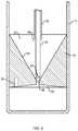
- FIG. 1is a diagram illustrating a separation system 1700 showing different components of a fluid inside the container 1702 after centrifugation.
- the least dense fluid 2000will be above the insert 1300 .
- the insertcan be made of a material of a certain density such that after centrifugation of blood, including blood from marrow, the insert spans the space between the least dense plasma 2000 and the dense red cells 2004 , with the intermediate dense material 2002 , e.g., nucleated cells, residing in the upper funnel-shaped portion 1304 of the insert.
- the separation system 1700can include a vent 1716 disposed in the top 1706 of the container 1702 and a fluid port 1718 disposed in or adjacent the top 1706 .
- the air vent 1716can prevent a vacuum from being created when fluid is withdrawn from the container 1702 .
- a cannula assembly 1500 with a closed end 1502is inserted through the injection port 1714 .
- a clamp 1800can be applied to sidewall of container 1702 to hold the insert 1300 in place during subsequent fluid extraction.
- the closed end 1502 of the cannula assemblybutts against the insert and closes the through hole 1308 of the insert.
- the closed end of the cannula assembly 1500 and the insertcan form a seal, thus isolating denser fluid component or components beneath the seal from fluid components above the seal.
- the cannula assemblyincludes two cannulae, an inner cannula 1508 and an outer cannula 1510 , that fit coaxially into each other.
- the cannula assemblyincludes a series of two parallel side holes or ports in the two cannulae to line up at different predetermined heights above the closed distal end 1502 .
- a first set of side ports 1506can be located near the closed distal end 1502 .
- a second set of side ports 1504can be located above the upper funnel-shaped portion 1304 of insert 1300 .
- Fluid above the distal end 1502 of the cannula assemblycan be removed in at least two fractions or components based on these two different predetermined heights. Fluid can be removed through the cannula assembly 1500 into connected syringes 1802 , 1804 using valve 1806 .
- top side ports 1504when the top side ports 1504 are aligned and opened, fluid above the top side ports can be extracted into a first syringe 1802 through inner cannula 1508 .
- the top side ports in the cannula assembly 1500are misaligned and sealed off, while the bottom side ports are aligned and opened.
- the side portsmay be radially offset by 90 degrees, requiring a relative rotation of 90 degrees to change which ports are aligned.
- FIGS. 2A-2Care a series of sequential diagrams illustrating the extraction of fluid components using a separation system 2100 , the system including a container 2102 having a movable bottom or plunger 2104 . Centrifugation separates the fluid in the container by density into separate components or fractions.
- FIG. 2Aillustrates the position of an insert, such as insert 2600 , in relation to three components of a fluid in the separation system 2100 after centrifugation.
- the componentsare a low density fraction 2000 , such as plasma, a medium density fraction 2002 , such as buffy coat or nucleated cells, and a high density fraction 2004 , such as red blood cells.
- the usertakes the syringe or container 2102 out of the centrifuge. As shown in FIGS. 2A-2B , the user then uncaps the luer connector of port 2118 , attaches a plasma extraction syringe 2300 , and pulls back on the plunger.
- the insert 2600has risen to the top of the syringe or container 2102 and effectively seals off port 2118 connected to the plasma extraction syringe. At this point the user uncaps the air vent 2116 making the collection syringe or container 2102 no longer under vacuum pressure.
- a second target cell extraction syringe 2302 with a cannula 2400 attachedis then inserted through the center injection port 2114 .
- the insert 2600always ends up at the top of the collection syringe or container 2102 after removal of the plasma and 2) the height of the insert 2600 is known, then the distance between the top of the injection port 2114 and bottom of the through holes 2610 , 2608 of the insert 2600 is always the same after removal of the plasma.
- the length of the cannula 2400is such that it reaches just to the bottom of the center through hole 2608 in the insert 2600 after removal of the plasma.
- a system for separating components of different densities from a physiological fluid containing cells using a centrifugeincludes a container having a top, a sidewall extending from the top, and a bottom disposed opposite the top and in sealing engagement with the sidewall.
- the containerdefines a cavity for receiving the fluid.
- the systemincludes an insert slidably disposed in the cavity of the container.
- the insertdefines a lumen through the insert, the lumen including a hole and a funnel-shaped upper portion in fluid communication with the hole.
- the lumenforms an open fluid path between opposite ends of the insert.
- the inserthas a density such that upon centrifugation a selected component of the fluid resides within the lumen.
- a container portis disposed in the top of the container to transfer the fluid into the container and to withdraw a fluid component other than the selected component from the container.
- the systemfurther includes a manifold that includes a manifold port, a vent to vent the container, and a connector to couple to the container port.
- a cannulais receivable in the manifold port and extendable through the container port into the container and into the lumen of the insert to withdraw the selected component from the lumen.
- the cannulacan include a closed end to close the hole in the insert and a side port to withdraw the selected component.
- the cannula and the insertmay form a seal when the closed end of the cannula closes off the hole in the insert.
- the cannulaa first cannula
- the systemfurther includes a second cannula extendable through the container port to withdraw the component other than the selected component.
- the second cannulamay be receivable in the manifold port.
- the systemmay include two manifolds, each including a manifold port, a vent to vent the container, and a connector to couple to the container port, and the first cannula can be receivable in the manifold port of one manifold while the second cannula can be receivable in the manifold port of the other manifold.
- the containercan be a syringe and the bottom can be movable, i.e., a plunger, which can have a removable handle.
- the plungeris a first plunger and the system further includes a second plunger disposed in the syringe below the first plunger to move the first plunger, for example, to transfer the fluid into the container.
- the systemmay further include a clamping mechanism to hold the insert in place after centrifugation, the clamping mechanism being configured to press the sidewall of the container inward against the insert.
- a method of separating components of different densities from a fluid containing cells using a centrifugeincludes receiving the fluid in a separation system such as the separation system described above, and applying centrifugal force to the separation system. The method further includes, after centrifugation, withdrawing a fluid component other than the selected component through the container port; coupling a manifold to the container port, the manifold including a manifold port and a vent to vent the container; extending a cannula through the container port into the container and into the lumen of the insert, the cannula receivable in the manifold port; and withdrawing the selected component with the cannula from the lumen of the insert.
- Withdrawing the selected componentmay include withdrawing the selected component through a side port in the cannula.
- the cannulais a first cannula and withdrawing the component other than the selected component includes extending a second cannula through the container port, the second cannula receivable in the manifold port, and withdrawing the component other than the selected component with the second cannula.
- the manifoldcan be coupled to the container before the withdrawing of the component other than selected component.
- the methodmay further include with a clamping mechanism, holding the insert in place after centrifugation.
- a system for separating components of different densities from a physiological fluid containing cells using a centrifugeincludes a container, having a bottom, a top disposed opposite the bottom, and a sidewall extending from the top, the container defining a cavity for receiving the fluid.
- An insertis slidably disposed in the cavity and defines a lumen through the insert, the lumen including a hole and a funnel-shaped upper portion in fluid communication with the hole.
- the inserthas a density such that upon centrifugation a selected component of the fluid resides within the lumen.
- the lumenforms an open fluid path between opposite ends of the insert.
- a container portis disposed in the top of the container.
- An extraction capis provided to couple to the top of the container, the extraction cap including a cannula assembly receivable in the container port.
- the cannula assemblyis extendable into the cavity of the container to butt against the insert and to withdraw the selected component from the lumen of the insert.
- the cannula assemblycan include an inner cannula coaxially disposed within an outer cannula.
- the inner cannulamay include a closed end to close the hole in the insert and a side port to withdraw the selected component, the inner cannula and the insert forming a seal when the closed end of the inner cannula closes off the hole in the insert.
- the outer cannulamay include an open end displaced from the distal end of the cannula assembly to withdraw fluid at a predetermined height above the distal end of the cannula assembly.
- the extraction capincludes a first port in fluid communication with the inner cannula and a second port in fluid communication with the outer cannula.
- the systemmay further include a first syringe to couple to the first port and a second syringe to couple to the second port.
- the capmay include an assembly tab adjacent the first and second ports, the assembly tab extending from the cap to prevent the second syringe from coupling to the first port.
- the systemmay further include a lock-out element on the second syringe.
- the lock-out elementincludes a tab that locks a plunger of the first syringe until second syringe is removed from the cap.
- the extraction capincludes an outer part and an inner part, the inner part carrying the needle assembly and being movable relative to the outer part.
- the capmay include a locking screw coupled to the outer part and positioned at an angle relative to inner part to push the inner part toward the container with rotation of the locking screw.
- a method of separating components of different densities from a fluid containing cells using a centrifugeincludes receiving the fluid in a separation system, the system including a container having a bottom, a top disposed opposite the bottom, and a sidewall extending from the top, the container defining a cavity for receiving the fluid.
- a container portis disposed in the top of the container.
- An insertis slidably disposed in the cavity of the container, the insert including a funnel-shaped upper portion and a hole therethrough, the insert having a density such that upon centrifugation a selected component of the fluid resides within the upper portion of the insert.
- the methodincludes applying centrifugal force to the system and inserting a cannula into the container through the container port to butt against the insert, the cannula having one or more side ports displaced from a distal end of the cannula.
- the methodfurther includes withdrawing the selected component through the side ports in the cannula; ejecting at least a portion of the withdrawn component through the side ports causing one or more fluid jets in the funnel-shape upper portion of the insert to release cells that adhere to the insert; and withdrawing the ejected portion and cells released by the fluid jets through the side ports.
- the insertcan be rigid.
- the volume contained in the lumen upper portion of the insertcan be between 5% and 20% of the volume of the container cavity.
- the selected componentalso referred to herein as a target fraction
- the component other than the selected componentcan be blood plasma.
- Embodiments of the current inventionovercome the limitations of known devices for concentration of cells sourced from marrow or other tissue.
- the insert of the separation devicedoes not form a closed recess or a depression or indent to capture cells, but rather allows for the natural sedimentation of the fluid within the container and through the insert.
- the insertdefines a lumen that has at least one relatively large through hole or channel, including a funnel-shaped upper portion, that allows for the free flow of fluid within the container and through the insert and does not interfere with the natural layering of different density components of the fluid.
- the insertidentifies the location of a layer of interest, including the target cells.
- the funnel-shaped upper portion and the through holereduce the cross-sectional area and increase the thickness of the layer of interest. This facilitates extraction of the target cells and contributes to a high yield and high concentration of the target cells.
- Embodiments of the current inventionovercome limitations of other systems that use inserts or buoys without a through hole and where the fluid path under centrifugation is confined to the distance between the inner wall of a container or tube and the outer walls of the inserts or buoys.
- minor clots, particles, or other inconsistencies in the fluidcan lodge between the walls of the tube and the buoys interfering with the natural layering of the different density components of the fluid.
- the insert(s) describedincludes a density selected such that after centrifugation the target cells reside within the hole, the funnel-shape upper portion, or lumen defined by the insert.
- the insertUnder gravitational force the insert floats freely within the container with substantially all of the fluid flowing through the hole or lumen of the insert, but not between the outer wall of the insert and the inner wall of the container. The distance between the inner wall of the container and the outer wall of the insert creates enough space to allow the insert to move freely within the container.
- Embodiments of apparatus and methods for separating components of a fluidcan be combined with devices and methods to access and source, e.g., aspirate, tissue, such as the aspiration needle assemblies described in International Application No. PCT/US2010/036696.
- tissuee.g., loaded into a separation system
- the systemcan be centrifuged.
- the target cellsnaturally sediment into the through hole or lumen of the floating insert.
- These cellsare then isolated by means of a cannula.
- the closed end of the cannulacan close the hole in the insert.
- the target cells residing in the hole of lumen of the floating insertmay be sealed from fluid below while fluid above the insert is removed through a cannula.
- the combination of the cell concentration and separation apparatus described herein with an aspiration apparatusallows a clinician the ability to access subcutaneous tissue in a less traumatic manner and then concentrate nucleated cells from that tissue aspirate.
- the apparatuscan be combined, e.g., coupled or connected, by means of tubing and fluid ports, including luer connections, to create a total solution from aspiration to concentration.
- FIG. 1illustrates a separation system showing different components of a fluid after centrifugation.
- FIGS. 2A-2Care a series of sequential diagrams illustrating the extraction of fluid components using a separation system having a movable bottom.
- FIG. 3is an exploded view of a system for separating components of difference densities from a physiological fluid according to an example embodiment of the invention.
- FIG. 4is a perspective view of a container including an insert according to an example embodiment of the invention.
- FIG. 5is a perspective view of the container of FIG. 3 positioned in a base including a clamping mechanism.
- FIG. 6is a side view of an extraction cap according to an example embodiment of the invention.
- FIG. 7is a side view of a system including the container and base of FIG. 5 and the extraction cap of FIG. 5 .
- FIG. 8is a sectional view of the system of FIG. 7 .
- FIG. 9illustrates a needle assembly positioned in an insert.
- FIG. 10Aillustrates a system for concentrating cell according to another example embodiment of the invention.
- FIG. 10Bis a perspective view of a double plunger syringe including an insert.
- FIGS. 11A-11Cillustrate movement of the plungers of the double plunger syringe of FIG. 10A .
- FIG. 12illustrates inserts for use with a system for concentrating cells according to example embodiments of the invention.
- FIG. 13illustrates the collection syringe of FIG. 11 positioned in a holder including a clamping mechanism.
- FIG. 14Aillustrates elements of the system of FIG. 10A arranged for extraction of fluid components from the container.
- FIG. 14Bis a detailed view of the cannula and manifold of FIG. 14A .
- FIG. 15illustrates a cannula positioned against an insert, the cannula including a side port displaced from the distal end of the cannula to withdraw fluid at a predetermined height above the distal end, e.g., above the insert, to withdraw substantially only plasma.
- FIG. 16illustrates a cannula positioned against an insert, the cannula including a side port displaced from the distal end of the cannula to withdraw fluid at a predetermined height above the distal end, e.g., within the insert, to withdraw substantially all of the target fraction.
- FIG. 17illustrates an alternative embodiment including an extraction syringe coupled to a collection syringe for withdrawing a fluid component other than a selected component, e.g. for withdrawing plasma.
- FIG. 18illustrates a separation system according to another example embodiment of the invention.
- FIG. 19illustrates the separation system of FIG. 18 showing different components of a fluid after centrifugation.
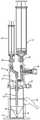
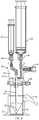
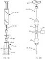
- FIG. 3is an exploded view of an improved system 10 for separating components of difference densities from a physiological fluid according to an example embodiment of the invention.
- System 10includes a base 12 , a separation vial (container) 14 , a float (insert) 16 disposed in the vial 14 , and an extraction cap 18 with syringes 20 , 22 and a cannula assembly including extraction needles (cannulae) 24 , 25 .
- the float 16should have a density that matches that of the buffy coat, whose density is roughly 1.06 g/cc.
- a polystyrene materialwas selected to manufacture the insert because the material's density is close to that of buffy coat.
- Small slugs 56FIG. 9 , e.g., pieces of stainless steel, can be added into the float to adjust its density. The process of testing a device in blood to ensure that the density matches the desired density can be repeated for new batches of plastic, e.g., during manufacturing, or for testing different materials.
- the materials of the systemare polycarbonate for most of the parts with the vial being PET (Polyethylene teraphthalate plastic) and the float polystyrene, as described above.
- Other suitable materials for the floatmay be polyethylene or polypropylene materials which tend to be less sticky to cells than polystyrenes. However, the densities of these materials are lower than that of buffy coat, so a larger metal material may need to be incorporated into the float to achieve the desired density.
- Another optionis to coat the surface of the float and the inside of the vial with a substance that prevents cells form sticking, for example, a coating from the company Hydromer.
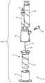
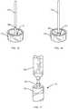
- FIG. 4is a perspective view of container 14 including an insert 16 according to an example embodiment of the invention.
- Container 14is a vial that has a bottom 13 , a top 17 disposed opposite the bottom, and a sidewall extending from the top, the top including a lid 19 to close the container.
- the vialdefines a cavity for receiving fluid.
- a physiological fluid containing cells, such as blood or marrow,is introduced into the separation vial 14 via a port 28 prior to centrifugation. After the fluid is centrifuged, the separation vial 14 is placed into the base 12 .
- the base 12has a lever 26 with a cam 27 that locks the vial to the base by deforming the vial wall 15 .
- This deformationlocks the float 16 inside the vial 14 in place so that it cannot move.
- the cam and lever of base 12operate as a clamping mechanism that, when engaged, prevents movement of the float. Movement of the float, such as during the extraction procedures described below, can disrupt the target cell layer, e.g., the buffy coat.
- the cap or lid 19 of the vial 14includes a silicone septum 30 and air vents 32 . As shown in FIGS. 4 and 5 , four air vents 32 are arranged around the septum 30 and four protrusions 60 extend from the lid 19 .
- the extraction needles (cannulae) 24 , 25are inserted through the septum 30 , which functions as a port into the container. The air vents are included so that one does not pull a vacuum when extracting the target cells or the plasma serum.
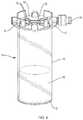
- FIG. 6is a side view of an extraction cap 18 according to an example embodiment of the invention.
- Extraction cap 18is distinct from the lid 19 and configured to couple to the top of the vial (container) 14 .
- the extraction capincludes the cannula assembly, including needles (cannulae) 24 and 25 , which are receivable in container port 30 .
- the extraction cap 18includes an outer part 31 and an inner part 33 movable with respect to the outer part.
- the outer part 31which includes apertures 62 to engage the protrusions 60 of the lid, snaps onto the top 17 of the vial 14 .
- the inner part 33includes two ports 36 , 38 for connecting the two syringes 20 , 22 to the inner and outer needles (cannulas) of the extraction cannula assembly.
- An assembly tab 42 on the inner part 33ensures that the larger syringe 20 can only be connected to the port that is in fluid communication with the outer extraction needle 25 .
- a lock-out tab 44is mounted on the large syringe 20 that forces the user to activate the large syringe first.
- the lock-out tab 44blocks the plunger of syringe 22 .
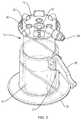
- the extraction cap 18is placed over the vial 14 , as illustrated in FIGS. 7 and 8 .
- the extraction needles 24 , 25are advanced through the silicone septum (container port) 30 and into the vial 14 .
- the extraction cap 18snaps onto the lid of the vial.
- the syringe/needle assemblyis pushed down by the operator so that the distal end of the needle assembly bottoms out into the funnel in the float 16 ( FIG. 9 ).
- the locking screw 34is then tightened. This screw is at an angle. As the screw is tightened, it slightly pushes the needle assembly down to ensure that it fully engages the bottom of the float.
- the locking screw 34is positioned at a small angle within the horizontal plane. In the embodiment of FIG. 3 , the locking screw 34 is angled out of the horizontal plane to perform the same function.
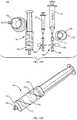
- the extraction cannula assemblyincludes an inner needle (inner cannula) 24 and an outer needle (outer cannula) 25 .
- the open distal end 46 of outer needle 25is positioned at a set distance from the distal end 48 of the inner needle 24 such that the outer needle sits at or near the top of the float 16 .
- the outer needleis used to extract the serum (plasma).
- FIG. 9illustrates the needle assembly positioned in the float (insert) 16 .
- the inner needle 24has a distal taper and multiple holes (ports) 40 , e.g., 3 side holes, at or near its distal end 48 .
- the inner needle 24sits in the bottom of the float and plugs hole 52 in the float.
- the extraction processstarts with the outer needle 25 , which is in fluid communication with large syringe 20 .
- the serumis removed until bubbles are seen in the syringe 20 .
- the selected componente.g., stem cells, buffy coat
- the selected componentis removed using the small syringe 22 and the inner needle 24 , the selected component being withdrawn through holes 40 of inner cannula 24 .
- the cell solution that has been removed, or portion thereofis pushed back, e.g., ejected, into the float through the holes 40 causing one or more jets of fluid in the funnel-shaped portion of the float. This jet flushing releases the cells from the float wall 54 . The cells are then sucked up during a second withdrawal into the syringe 22 .
- Embodiments shown in FIGS. 3-9 and described hereinhave many advantages.
- One advantage of the double cannula extraction needleis that the operator only has to push the cannula assembly through the silicone septum of the separation vial once, which reduces the risk of mixing the separated fluid components in the vial.
- Other systemsrequire needles or cannulae to be inserted serially, which carries a higher risk of infection and of moving the target cells to be extracted.
- the extraction needle lockwhich includes a locking screw that, when tightened, drives the cannula assembly down into the float to ensure that the extraction needle (inner cannula) fully engages the bottom of the float.
- the locking screw of the needle lockmay be positioned at an angle with respect to the extraction needle, such that rotation of the screw drives the extraction needle down.
- the screwmay be at an angle out of the horizontal plane ( FIG. 3 ), or at an angle within the horizontal plane, as illustrated in FIGS. 6-8 .
- the lock-out tab on the larger syringeprevents an operator from using the small syringe first, thereby ensuring proper order of withdrawal of fluid components.
- FIGS. 10-17A system for separating components of different densities from a fluid containing cells and for concentrating cells according to another example embodiment of the invention is described below and illustrated in FIGS. 10-17 .
- a system for concentrating bone marrow or bloodis described, although the principles of the invention can be applied to other fluids, including other physiological fluids.
- the systemuses a container having a movable bottom, e.g., a syringe with at least one plunger, for both the collection and centrifugation of the fluid specimen.
- a system 100 for separating components of different densities from a fluid containing cells using a centrifugeincludes a collection syringe (container) 114 having a top 117 , a sidewall 115 extending from the top, and a bottom 113 , e.g., a plunger, disposed opposite the top and in sealing engagement with the sidewall.
- the containerdefines a cavity for receiving the fluid.
- An insert 116is slidably disposed in the cavity of the container 114 . Similar to insert 16 described above in reference to FIG. 9 , insert 116 defines a lumen through the insert, the lumen including a hole 52 and a funnel-shaped upper portion 50 in fluid communication with the hole.
- the lumenforms an open fluid path between opposite ends of the insert.
- the inserthas a density such that upon centrifugation a selected component of the fluid resides within the lumen.
- a container port 130e.g., a luer connector, is disposed in the top of the container 114 to transfer the fluid into the container and to withdraw a fluid component other than the selected component from the container.
- the systemfurther includes at least one manifold 160 that includes a manifold port 162 , a vent 164 to vent the container, and a connector 166 to couple to the container port 130 .
- a cannula 170 , 172( FIG. 14A ) is receivable in the manifold port 162 and extendable through the container port 130 into the container 114 and into the lumen of the insert 116 to withdraw the selected component from the lumen or a component other than the selected component.
- the systemcan include a clamping mechanism 112 that can also double as a syringe holder.
- the container of the systemcan be a syringe that includes a plunger having a removable handle (not shown) or a syringe 114 with two plungers as shown, plunger 123 having a handle and plunger 113 being without a handle.
- a 30 ml plasma extraction syringe 120is connected to a cannula 170 that fits through upper injection port 162 , manifold 160 and lower luer connection 166 .
- a 5 ml concentrate extraction syringe 122is connected to a cannula 172 that fits through upper injection port 162 , manifold 160 and lower luer connection 166 .
- the systemcan include a syringe holder 174 with washer on bottom and, optionally, O-ring 176 .
- the systemcan include two manifolds 160 , as illustrated in FIG. 10A .
- One manifold 160receives cannula 170 ; the other manifold receives cannula 172 .
- a standard 4-way manifoldmay be used for each manifold 160 .
- the standard manifoldincludes 3 fluid channels and a switch (e.g, valve) 168 .
- each of the fluid channelscan be selective closed or all channels can be open.
- all channelsare open.
- Vent 164 Coupled to the manifoldcan be a vent that has a micron filter. This way, a sterile environment can be maintained while venting during the extraction of fluid.
- the injection port 162 and the connector 166can be swabable luer ports, which can be swabbed or wiped, e.g., with alcohol, for good sterile procedure.
- the swabable luer portstypically include an elastomeric (e.g., rubber) membrane that includes a slit that is normally closed, but parts when a cannula or male luer connector is inserted. Such ports are beneficial when connections are to be air tight.
- the first stepis to use the double plunger syringe 114 (alternatively, a syringe with a removable handle) to fill the syringe with the blood or marrow specimen to be concentrated.
- FIGS. 11A-11Cillustrate movement of the plungers of the double plunger syringe 114 , such as during filling of the syringe with physiological fluid.
- the syringe port 130is coupled to another container containing the source tissue or to a tissue aspiration needle (not shown). Pulling back on the second plunger 123 via its handle forces the first plunger 113 under vacuum pressure to move back and the syringe is thus filled.
- the second plunger 123can be completely removed from the barrel of syringe 114 leaving behind the first plunger 113 that is not connected to a handle.
- the shortened profile of the syringe with the second plunger 123 removedfits into commonly used centrifuges.
- the second stepis to connect to the syringe 114 containing the specimen (e.g., fluid tissue), after the second plunger has been removed, a small micron vented luer cap 178 and then place the syringe inside the syringe tube holder 174 .
- the holder 174has a solid bottom and also has an O-ring 176 attached to the solid bottom ( FIG. 10A ).
- the O-ringlines up with the seal the plunger 113 makes with the outer wall 115 of the syringe barrel. Under high g-force, this O-ring serves to prevent any leaking from the syringe into the syringe tube holder 174 .
- a funnel shaped insert 116(also referred to herein as a funnel) with a hole in the center.
- the density of the funnelis such that after density separation, target cells from blood or marrow will reside inside of the funnel. Consequently, after density separation of blood or marrow, plasma will reside at the top of the syringe 114 nearest the Luer tip (container port) 130 , the target cells will reside inside of the funnel 116 , and red blood cells will reside beneath the funnel nearest the plunger 113 .
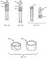
- Two example funnels 116 a , 116 bare shown in FIG. 12 .
- the funnel 116 a to the leftis made of REXOLITE. This material has a density of 1.05 and is easy to machine.
- a plastic materialmay be used, such as ABS by Dow Chemical (part #3105 FP EP) that has a density of 1.05 and is ideal for molding applications.
- a material that has a lower density than desiredcan have its density increased by adding screws or other material to the body of the funnel, as described above in reference to insert 16 of FIG. 9 .
- the funnelmay be made of two parts or two different plastics.
- many different shaped funnelswill work.
- a deeper, taller funnelsuch as funnel 116 b pictured to the right in FIG. 12
- a shallow, shorter funnelsuch as the clear REXOLITE funnel 116 a illustrated to the left
- a bowl-shaped funnel or a funnel that has an inflection pointsuch that the angle of the wall is steeper at the bottom compared to the top, are all possible funnel shaped inserts that can be used in embodiments of the invention.
- the funnel 116has an upper funnel shaped portion 50 and a through hole 52 at the bottom as illustrated with respect to insert 16 ( FIG. 9 ).
- the third stepis to take the syringe 114 and tube holder 174 from the centrifuge, place the syringe inside the clamping mechanism 112 and engage the clamp as illustrated in FIG. 13 .
- the pressure from the clampwill pinch the walls 115 of the syringe 114 so that the inner wall of the syringe barrel presses against the funnel 116 .
- This pressurewill freeze (i.e., lock) the funnel in place.
- the clamping mechanismcan include a lever 26 and cam 27 similar to the clamping mechanism described above in reference to FIGS. 5, 7 and 8 .
- the fourth stepis to remove the vented cap 178 from the collection syringe 114 and connect to the collection syringe, via the upper luer connection 130 , the 30 ml plasma extraction syringe 120 connected to cannula 170 via manifold 160 , as shown in FIG. 14A .
- Cannula 170fits through an upper injection port 162 connected to manifold 160 as shown in FIG. 14B .
- Also connected to manifold 162are a side air vent 164 and a lower luer connection 166 .
- the userpushes the extraction cannula 170 into the collection syringe.
- the cannulawill advance until it hits the funnel 116 that has been frozen in place by the clamping mechanism 112 .
- cannula 170has a blunt closed end 171 and a hole 180 a certain distance above along its shaft. This hole is positioned to be high enough to extract only the plasma above but not the contents of the funnel 116 .
- the plasma extraction cannula 170is removed from the collection syringe 114 and the plasma extraction syringe 120 is disconnected from the manifold 160 .
- the syringe 120 and the manifold 160are disconnected from the luer fitting 130 of the collection syringe and removed.
- FIG. 16illustrates cannula 172 positioned against funnel (insert) 116 , the cannula including a side port 182 displaced from the distal end 173 of the cannula to withdraw fluid at a predetermined height above the distal end, e.g., within the funnel 116 , to withdraw substantially all of the target fraction.
- Extraction cannula 172works the same way as the 30 ml extraction cannula except that hole (side port) 182 positioned near the cannula's blunt distal end 173 is close to the bottom of the funnel 116 so that the contents of the funnel are removed through hole 182 when vacuum pressure is applied via syringe 122 .
- jet flushingdescribed above in reference to cannula 24 of FIG. 9 , may be employed by ejecting fluid through hole 182 into the funnel 116 to release cells that adhere to the funnel inner surface.
- each cannula 170 , 172includes a closed end 171 , 173 to close the hole 52 in the insert 116 and at least one side port 180 , 182 to withdraw a component of the fluid, be it the selected component, e.g., buffy coat, or a component other than the selected component, e.g., plasma.
- a component of the fluidbe it the selected component, e.g., buffy coat, or a component other than the selected component, e.g., plasma.
- Each cannula 170 , 172 and the insert 116may form a seal when the closed end of the cannula closes off the hole in the insert.
- FIGS. 10A-16Additional features of the above embodiment, as illustrated in FIGS. 10A-16 , are as follows:
- the collection syringe 114is vented and fluid removed by employing the following novel features (see, e.g., FIGS. 14A-14B ):
- the collection syringe 114is vented during the retrieval of the one or more target fractions.
- a target fractionis removed via a cannula using the negative pressure of an extraction syringe.
- the air vent 164 that used to accomplish thisis not part of either syringe but is connected to both syringes, e.g., via the manifold 160 .
- the luer tip 130 of the collection syringe 114is used as the extraction port.
- the third step in the separation procedureis to take the syringe 114 and tube holder 174 from the centrifuge and place it inside of the clamping mechanism 112 to engage the clamp and freeze the funnel 116 in place.
- the clamping mechanismis not used.
- An alternative to removing the plasma with a cannula after clamping the funnel 116 in placeis to attach a syringe 120 to the upper luer 130 of collection syringe 114 using a standard fem/fem luer connection and remove the plasma directly, without a cannula, by using the vacuum pressure of the two connected syringes. Since a standard luer connection is contemplated, the plasma can be removed under vacuum pressure by pulling back on the plunger of the plasma extraction syringe 120 . Thus, as the plasma is removed, the plunger 113 rises and the funnel 116 inside the barrel of the collection syringe 114 also rises.
- the userremoves the plasma until the funnel 116 reaches the top of the syringe 114 .
- the next stepis to remove the plasma extraction syringe 120 from the collection syringe 114 and connect to the collection syringe, via the upper luer connection 130 , a vented 5 ml PRP extraction syringe, e.g., syringe 172 coupled to manifold 160 .
- the target cellswill not re-mix because the walls of the funnel 116 prevent fluid turbulence or interference from the inner wall of the syringe barrel.
- the center hole of the funnel 116is sized such that at 1 G force, surface tension prevents fluid passage from below the funnel into the funnel.
- the PRP extraction syringe 122is connected to a cannula 172 that fits through an upper injection port 162 , connected to a manifold 116 that has a side air vent 164 and a lower luer connection 166 .
- the cannula 172can be shorter for this extraction process as the float 116 is at the top of the collection syringe 114 .
- the collection syringe 114is not vented during loading of the specimen but is vented during extraction the target fraction inside the funnel.
- the userpushes the extraction cannula 172 into the collection syringe. Since the insert 116 ends at the top of the syringe in this embodiment, the cannula 172 can be a set length, such that the cannula will advance the proper distance until it is approximately at the bottom of the funnel 116 . As described above in reference to FIG. 16 , this cannula has a blunt closed end to butt against the funnel 116 , and a hole (e.g., a port) positioned a certain distance above the blunt end.
- a holee.g., a port
- the holeis positioned such that it ends up close to the bottom of the funnel when the blunt end of the cannula butts against the funnel. This ensures that the contents of the funnel 116 can be removed through the cannula 172 with the PRP extraction syringe 122 .
- FIGS. 1 and 2illustrate embodiments described in previously filed application PCT/US2010/036696, which are useful to separate cells of a different fraction of a physiological fluid using centrifugation.
- the embodimentseach include a collection tube or container that contains a funnel (e.g., an insert or float having a funnel-shaped portion) with a through hole in the funnel.
- the tubeis designed to accept fluid, specifically blood or marrow.
- the funnelhas a density such that after centrifugation, cells are captured inside the funnel. Two of the methods described for removing the cells contained inside the funnel after centrifugation are summarized below.
- Method 1The first method involves the following procedures:
- Method 2The second method involves the following procedure:
- the firstinvolves freezing (e.g., clamping) the float in place and moving the needle assembly into the funnel to get the cells
- the second methodinvolves using the vacuum pressure from the syringe to move the funnel up so that it impales itself into the fixed blunt needle assembly under the cap of the syringe.
- WO 2010/138895 A2e.g., FIGS. 13-33 and associated text, for a more complete description of the two methods described above.
- the apparatus and methodinclude an upper and a lower funnel that are disposed inside the collection tube (container).
- bloodis loaded into a tube (container) 214 that defines a cavity that serves as the collection chamber for fluid.
- the tube 214has an injection port 228 and an air vent 229 .
- a flexible, optionally, clear tube 205Inside the collection tube 214 and in fluid communication with the injection port 228 is a flexible, optionally, clear tube 205 that is attached to a funnel 210 (referred to as the first or upper funnel) also disposed in the container 214 .
- the density of the upper funnel 210is less than blood plasma.
- the density of the upper funnelcan be about 1.0.
- the bulk of the upper funnel 210is floating above the plasma 2000 , as illustrated in FIG. 19 .
- the bottom point of the upper funnel 210has sunk slightly into the plasma or is in contact with the plasma.
- the funnel 210is narrower than the diameter of the collection tube 214 .
- the funnel 210has stabilization fins 215 at the top that extend from the funnel to approximately the sidewall of the tube 214 without touching the tube. These fins 215 are placed in such a manner that the upper funnel 210 remains oriented vertically with respect to the collection tube.
- the flexible tube 205is attached at one end to the portion of the upper funnel where through hole 220 is located in the funnel.
- Tube 205can be a small diameter clear tube that can flex and curl in on itself. Fluid is added to the collection tube 214 through the port 228 with a syringe. The fluid then travels through the length of flexible tube 205 and exits through hole 220 in the upper funnel 210 into the hollow chamber of collection tube 214 . Fluid is removed from the chamber through the same path.
- Beneath the upper funnel 210is a second funnel 216 that has a density of about 1.06, which is a higher density than the upper funnel and which allows the lower funnel 216 to float at the intermediate zone between red cells 2004 and plasma 2000 .
- the lower funnel 216has a through hole 52 , similar to other funnel shaped inserts described herein. Because the funnel 216 is open at the top and the bottom, it results in cleaner fluid flow and cleaner separation of components of the fluid, e.g., red cells, plasma, and target cells in the intermediate layer 2002 between red cells and plasma.
- the usercan attach a syringe to the upper port 228 and begin to retrieve plasma first.
- the upper funnel 210sinks as fluid in the chamber of tube 214 is removed but initially remains floating on the top of the fluid. After the desired amount of plasma has been removed, the user can switch syringes and begin to remove the remaining fluid above the lower funnel 216 and the contents of what is inside the lower funnel.
- the upper funnel 210continues to sink until it hits the lower funnel 216 .
- the angle of the upper funnel 210is steeper than the angle of the lower funnel 216 so that the upper funnel fits into the lower funnel.
- the upper funnel 210can have bottom stabilization fins 225 , so that the point of the upper funnel stops a certain distance below the bottom of the lower funnel 216 . This can also be accomplished by making the upper funnel 210 a certain height so that the upper stabilization fins 215 contact the upper surface of the lower funnel 216 .
- a clamp 212can be added after centrifugation that pinches the sidewall of the collection tube, such that the sidewall deforms and pinches against an outer surface of the lower funnel. In this way, the lower funnel 216 can be clamped in place and does not move as the upper funnel 210 mates with it during extraction of fluid. This allows the user to only withdraw the contents of the lower funnel 216 but not any fluid which is contained beneath the lower funnel.
- red cells 2004are below the lower funnel 216
- target cells of the density desired (e.g., buffy coat) 2002are inside the lower funnel
- plasma 2000is above the target cells
- the upper funnel 210is floating on top of the plasma.
- the userfirst removes plasma 2000 by attaching a syringe (not shown) to the center port 228 ( FIG. 18 ) of tube 214 and pulling back on the plunger of the syringe. This causes fluid to flow through the hole (port) 220 at the bottom of the upper funnel 210 , through the flex tube 205 and into the syringe.
- the usercan remove as much plasma as is desired.
- the usercan remove the syringe containing the plasma and attach a second syringe (not shown) and remove the remaining fluid that is contained above and inside the lower funnel 216 .
- the stabilization fins 215 , 225 and the relative height of the two funnels 210 , 216can be adjusted such that the upper funnel 210 dead ends against the lower funnel 216 so that no fluid from beneath the lower funnel is removed during the extraction process.
- the double plunger collection syringe described hereinmay be used to separate fluid components other than those described herein and may be used in applications other than those described herein.
- the example manifold disclosed hereinincluding the luer connection ports and micron vent, may be used to transfer fluids in a sterile manner in other applications, and may be used with syringes, cannulas, and containers other than those described herein.
- inserts other than those illustrated and described hereinmay be used in combination with containers, cannulas and syringes to separate components of a fluid. For example, inserts need not have a density as described herein.
Landscapes
- Health & Medical Sciences (AREA)
- Chemical & Material Sciences (AREA)
- Heart & Thoracic Surgery (AREA)
- General Health & Medical Sciences (AREA)
- Hematology (AREA)
- Chemical Kinetics & Catalysis (AREA)
- Vascular Medicine (AREA)
- Clinical Laboratory Science (AREA)
- Engineering & Computer Science (AREA)
- Anesthesiology (AREA)
- Biomedical Technology (AREA)
- Life Sciences & Earth Sciences (AREA)
- Animal Behavior & Ethology (AREA)
- Public Health (AREA)
- Veterinary Medicine (AREA)
- Analytical Chemistry (AREA)
- Cardiology (AREA)
- Pathology (AREA)
- External Artificial Organs (AREA)
- Centrifugal Separators (AREA)
- Apparatus Associated With Microorganisms And Enzymes (AREA)
Abstract
Description
- a) The collection syringe (container)114 is centrifuged ‘luer tip up’ and an O-ring or gasket is used to keep the syringe liquid-tight during centrifugation. If a syringe is centrifuged with the luer tip facing up, no cap or a vented cap for the luer tip should be used; otherwise the syringe distorts and leaks.
- b) The use of luer connectors, injection ports, vented caps and a manifold160 as a means to both 1) vent the collection syringe (container) and 2) insert a cannula into the syringe through the luer tip to extract fluid.
- a) The connection between the
extraction cannulas extraction syringes - b) The seal around the
upper injection port 162 and the cannula (170,172) that has pierced it is also air tight. - c) The column of the manifold160 is air tight with the exception of the
air vent 164 at right angle to the syringes. - d) The
connection 166 to thecollection syringe 114 is air tight.
- a) The connection between the
- a) After centrifugation, pinch the funnel in place by applying a clamp on the outside of the tube (e.g., container having a fixed bottom). The pressure on the tube causes the tube to flex. This then causes the inside wall of the tube to pinch against the outside wall of the funnel.
- b) Once the funnel is secured in place, a double needle apparatus (inner cannula within outer cannula) is inserted through a center port. The blunt tip of the needle mates with the center hole of the funnel blocking off fluid below the funnel from fluid above the funnel.
- c) The upper access hole (side port) of the double needle extracts all fluid that resides above the top of the funnel
- d) The lower access hole (side port) of the double needle extracts all fluid that resides inside the funnel.
- a) The fluid is loaded into a syringe (e.g., a container having a movable bottom or plunger) containing the funnel; the syringe can have no plunger handle or can have a removable plunger handle
- b) The syringe has a center luer connection and a side luer connection, both of which are closed.
- c) In one example, the center luer connection on the underside, inside the barrel of the syringe, has connected to it a blunt needle with side ports
- d) After centrifugation, the target cells reside inside the funnel
- e) Upper fluid (plasma) is removed via a plasma-syringe through the side luer connection. Because the system is a syringe, it is under vacuum pressure; consequently, as fluid is removed, the funnel and plunger move up.
- f) Once the majority of the fluid has been removed, the blunt end of the needle meets the center hole of the rising float (funnel) and effectively seals all fluid above the float from fluid below the float. The port retrieving the plasma also mates with the float simultaneously so that no further fluid can be removed from the side port once the blunt needle impales the rising float.
- g) The plasma syringe is removed and a vented cap added which now makes the system not under vacuum pressure.
- h) Another syringe is connected to the center port and the target cells are removed
Claims (7)
Priority Applications (1)
| Application Number | Priority Date | Filing Date | Title |
|---|---|---|---|
| US14/764,115US10603665B2 (en) | 2013-01-29 | 2014-01-29 | Cell concentration devices and methods that include an insert defining a lumen and a cannula assembly |
Applications Claiming Priority (4)
| Application Number | Priority Date | Filing Date | Title |
|---|---|---|---|
| US201361757993P | 2013-01-29 | 2013-01-29 | |
| US201361897587P | 2013-10-30 | 2013-10-30 | |
| US14/764,115US10603665B2 (en) | 2013-01-29 | 2014-01-29 | Cell concentration devices and methods that include an insert defining a lumen and a cannula assembly |
| PCT/US2014/013636WO2014120797A1 (en) | 2013-01-29 | 2014-01-29 | Cell concentration devices and methods |
Related Parent Applications (1)
| Application Number | Title | Priority Date | Filing Date |
|---|---|---|---|
| PCT/US2014/013636A-371-Of-InternationalWO2014120797A1 (en) | 2013-01-29 | 2014-01-29 | Cell concentration devices and methods |
Related Child Applications (1)
| Application Number | Title | Priority Date | Filing Date |
|---|---|---|---|
| US16/835,053DivisionUS20200324285A1 (en) | 2013-01-29 | 2020-03-30 | Cell concentration devices and methods that include an insert defining a lumen and a cannula assembly |
Publications (2)
| Publication Number | Publication Date |
|---|---|
| US20160008808A1 US20160008808A1 (en) | 2016-01-14 |
| US10603665B2true US10603665B2 (en) | 2020-03-31 |
Family
ID=50239924
Family Applications (4)
| Application Number | Title | Priority Date | Filing Date |
|---|---|---|---|
| US14/764,115Active2035-03-17US10603665B2 (en) | 2013-01-29 | 2014-01-29 | Cell concentration devices and methods that include an insert defining a lumen and a cannula assembly |
| US16/835,053AbandonedUS20200324285A1 (en) | 2013-01-29 | 2020-03-30 | Cell concentration devices and methods that include an insert defining a lumen and a cannula assembly |
| US17/715,222ActiveUS11660603B2 (en) | 2013-01-29 | 2022-04-07 | Cell concentration devices and methods including a syringe and a syringe holder |
| US18/320,038ActiveUS12109566B2 (en) | 2013-01-29 | 2023-05-18 | Cell concentration devices and methods including a syringe and a syringe holder |
Family Applications After (3)
| Application Number | Title | Priority Date | Filing Date |
|---|---|---|---|
| US16/835,053AbandonedUS20200324285A1 (en) | 2013-01-29 | 2020-03-30 | Cell concentration devices and methods that include an insert defining a lumen and a cannula assembly |
| US17/715,222ActiveUS11660603B2 (en) | 2013-01-29 | 2022-04-07 | Cell concentration devices and methods including a syringe and a syringe holder |
| US18/320,038ActiveUS12109566B2 (en) | 2013-01-29 | 2023-05-18 | Cell concentration devices and methods including a syringe and a syringe holder |
Country Status (2)
| Country | Link |
|---|---|
| US (4) | US10603665B2 (en) |
| WO (1) | WO2014120797A1 (en) |
Cited By (9)
| Publication number | Priority date | Publication date | Assignee | Title |
|---|---|---|---|---|
| US20200276588A1 (en)* | 2017-09-22 | 2020-09-03 | Sartorius Stedim Biotech Gmbh | Sterile probe sampling for a single-use vessel |
| US11478787B2 (en) | 2018-07-09 | 2022-10-25 | Hanuman Pelican, Inc. | Apparatus and methods for separating blood components |
| US11534534B2 (en) | 2018-07-09 | 2022-12-27 | Hanuman Pelican, Inc. | Apparatus and methods for processing blood |
| US11559613B2 (en) | 2019-02-06 | 2023-01-24 | Hanuman Pelican, Inc. | Apparatus and methods for concentrating platelet-rich plasma |
| US11654428B2 (en) | 2019-01-21 | 2023-05-23 | Vias Partners, Llc | Methods, systems and apparatus for separating components of a biological sample |
| US11660603B2 (en) | 2013-01-29 | 2023-05-30 | Cervos Medical Llc | Cell concentration devices and methods including a syringe and a syringe holder |
| US12007382B2 (en) | 2019-10-31 | 2024-06-11 | Crown Laboratories, Inc. | Systems, methods and apparatus for separating components of a sample |
| US12134092B2 (en) | 2017-11-30 | 2024-11-05 | Cervos Medical Llc | Apparatus and method for centrifuging a biologic |
| US12440835B2 (en) | 2020-01-21 | 2025-10-14 | Vias Partners, Llc | Methods, systems and apparatus for separating components of a biological sample |
Families Citing this family (13)
| Publication number | Priority date | Publication date | Assignee | Title |
|---|---|---|---|---|
| US9272083B2 (en) | 2009-05-29 | 2016-03-01 | Endocellutions, Inc. | Apparatus and methods for aspirating and separating components of different densities from a physiological fluid containing cells |
| CN104491944A (en)* | 2014-11-19 | 2015-04-08 | 沈阳优吉诺生物科技有限公司 | Plasma extracting device and extracting method thereof |
| ES2671747T3 (en)* | 2015-01-22 | 2018-06-08 | The Regents Of The University Of California | Compositions and methods for separation of platelet rich plasma |
| WO2016153590A2 (en)* | 2015-01-22 | 2016-09-29 | The Regents Of The University Of California | Platelet rich plasma and bone marrow aspirate cell separation and removal methods and devices |
| CN107771079B (en) | 2015-07-02 | 2021-11-05 | 阿瑟雷克斯股份有限公司 | Method and apparatus for preparing an enriched biological fluid |
| AU2016359598B2 (en)* | 2015-11-24 | 2021-10-07 | Royal Biologics | Methods and apparatus for separating fluid components |
| WO2019018272A1 (en) | 2017-07-17 | 2019-01-24 | Boston Scientific Scimed Inc. | Cryotherapeutic delivery device |
| US12313623B2 (en)* | 2019-01-07 | 2025-05-27 | 1866402 Ontario Limited | Blood separation and analysis device and methods |
| US11320345B2 (en) | 2019-03-18 | 2022-05-03 | Avantor Fluid Handling, Llc | Adjustable volume sampling system (AVSS) |
| CN114364783A (en)* | 2019-08-06 | 2022-04-15 | Bd科斯特公司 | Disposable device for venting a sealed container and taking a sample therefrom |
| DE102019121723A1 (en)* | 2019-08-13 | 2021-02-18 | Sarstedt Ag & Co. Kg | Separation bodies and methods for separating blood plasma and blood cells |
| EP3799896B1 (en) | 2019-10-04 | 2025-09-10 | Arthrex, Inc | Devices and methods for making therapeutic fluids |
| TWI742754B (en)* | 2020-07-08 | 2021-10-11 | 輔仁大學學校財團法人輔仁大學 | Liquid separation kit |
Citations (52)
| Publication number | Priority date | Publication date | Assignee | Title |
|---|---|---|---|---|
| US3814248A (en) | 1971-09-07 | 1974-06-04 | Corning Glass Works | Method and apparatus for fluid collection and/or partitioning |
| US3957654A (en) | 1974-02-27 | 1976-05-18 | Becton, Dickinson And Company | Plasma separator with barrier to eject sealant |
| US4001122A (en) | 1973-08-22 | 1977-01-04 | Telan Corporation | Method and device for separating blood components |
| US4152270A (en) | 1976-05-06 | 1979-05-01 | Sherwood Medical Industries Inc. | Phase separation device |
| US4818418A (en) | 1984-09-24 | 1989-04-04 | Becton Dickinson And Company | Blood partitioning method |
| US4844818A (en) | 1987-10-23 | 1989-07-04 | Becton Dickinson & Company | Method for separating the cellular components of blood samples |
| US4917801A (en) | 1984-12-04 | 1990-04-17 | Becton Dickinson And Company | Lymphocyte collection tube |
| US4939087A (en) | 1987-05-12 | 1990-07-03 | Washington State University Research Foundation, Inc. | Method for continuous centrifugal bioprocessing |
| US5030341A (en) | 1987-04-03 | 1991-07-09 | Andronic Technologies, Inc. | Apparatus for separating phases of blood |
| US5053134A (en) | 1984-12-04 | 1991-10-01 | Becton Dickinson And Company | Lymphocyte collection tube |
| US5236604A (en) | 1991-05-29 | 1993-08-17 | Sherwood Medical Company | Serum separation blood collection tube and the method of using thereof |
| US5269927A (en) | 1991-05-29 | 1993-12-14 | Sherwood Medical Company | Separation device for use in blood collection tubes |
| US5271852A (en) | 1992-05-01 | 1993-12-21 | E. I. Du Pont De Nemours And Company | Centrifugal methods using a phase-separation tube |
| US5308506A (en) | 1987-04-03 | 1994-05-03 | Mcewen James A | Apparatus and method for separating a sample of blood |
| US5474687A (en) | 1994-08-31 | 1995-12-12 | Activated Cell Therapy, Inc. | Methods for enriching CD34+ human hematopoietic progenitor cells |
| US5489386A (en) | 1994-01-31 | 1996-02-06 | Applied Imaging | Density gradient medium for the separation of cells |
| US5577513A (en) | 1994-08-31 | 1996-11-26 | Activated Cell Therapy, Inc. | Centrifugation syringe, system and method |
| EP0493838B1 (en) | 1990-12-31 | 1997-05-28 | Robert Aaron Levine | Constituent layer harvesting from a centrifuged sample in a tube |
| US5641622A (en) | 1990-09-13 | 1997-06-24 | Baxter International Inc. | Continuous centrifugation process for the separation of biological components from heterogeneous cell populations |
| US5739033A (en) | 1989-09-20 | 1998-04-14 | Vivorx, Inc. | Physiological cell separation and method of separating cells using same |
| US5840502A (en) | 1994-08-31 | 1998-11-24 | Activated Cell Therapy, Inc. | Methods for enriching specific cell-types by density gradient centrifugation |
| US6051146A (en) | 1998-01-20 | 2000-04-18 | Cobe Laboratories, Inc. | Methods for separation of particles |
| US6123655A (en) | 1996-04-24 | 2000-09-26 | Fell; Claude | Cell separation system with variable size chamber for the processing of biological fluids |
| WO2001083068A1 (en) | 2000-04-28 | 2001-11-08 | Harvest Technologies Corporation | Blood components separator disk |
| US20020006360A1 (en)* | 2000-03-10 | 2002-01-17 | Neal David M. | Three stage needle for use with an autosampler |
| US6410334B1 (en) | 1998-08-07 | 2002-06-25 | Edi (Experimentelle & Diagnostische Immunologie) Gmbh | Method for determining the immune defense of blood and test kit for the same and use of a suitable blood sampling system |
| US6516953B1 (en) | 1998-12-05 | 2003-02-11 | Becton, Dickinson And Company | Device for separating components of a fluid sample |
| US20030205538A1 (en) | 2002-05-03 | 2003-11-06 | Randel Dorian | Methods and apparatus for isolating platelets from blood |
| WO2003099412A1 (en) | 2002-05-24 | 2003-12-04 | Biomet Manufacturing Corp. | Apparatus and method for separating and concentrating fluids containing multiple components |
| US6733433B1 (en) | 1998-12-24 | 2004-05-11 | Biosafe S.A. | Blood separation system particularly for concentrating hematopoietic stem cells |
| US20050109716A1 (en) | 2002-05-24 | 2005-05-26 | Michael Leach | Apparatus and method for separating and concentrating fluids containing multiple components |
| US20060273050A1 (en) | 2002-05-24 | 2006-12-07 | Higgins Joel C | Apparatus and method for separating and concentrating fluids containing multiple components |
| US20060273049A1 (en) | 2002-05-24 | 2006-12-07 | Leach Michael D | Method and apparatus for separating and concentrating a component from a multi-component material including macroparticles |
| US20060278588A1 (en) | 2002-05-24 | 2006-12-14 | Woodell-May Jennifer E | Apparatus and method for separating and concentrating fluids containing multiple components |
| US20070131612A1 (en) | 2005-10-27 | 2007-06-14 | Duffy Neil F Jr | Cell separation method and apparatus |
| US20070265558A1 (en) | 2006-05-02 | 2007-11-15 | Stemwell Llc | Stem cells derived from bone marrow for tissue regeneration |
| US7316932B2 (en) | 2001-10-01 | 2008-01-08 | Stemcell Technologies Inc. | Method for separating cells |
| US20080171951A1 (en) | 2005-03-23 | 2008-07-17 | Claude Fell | Integrated System for Collecting, Processing and Transplanting Cell Subsets, Including Adult Stem Cells, for Regenerative Medicine |
| US7445125B2 (en) | 2003-05-19 | 2008-11-04 | Harvest Technologies Corporation | Method and apparatus for separating fluid components |
| US7514075B2 (en) | 2001-12-07 | 2009-04-07 | Cytori Therapeutics, Inc. | Systems and methods for separating and concentrating adipose derived stem cells from tissue |
| US20090186065A1 (en) | 2008-01-18 | 2009-07-23 | Wake Forest University Health Sciences | Isolating and purifying cells for therapy |
| US7585670B2 (en) | 2001-12-07 | 2009-09-08 | Cytori Therapeutics, Inc. | Automated methods for isolating and using clinically safe adipose derived regenerative cells |
| US7595043B2 (en) | 2001-12-07 | 2009-09-29 | Cytori Therapeutics, Inc. | Method for processing and using adipose-derived stem cells |
| US7598089B2 (en) | 2006-04-19 | 2009-10-06 | Bioe, Inc. | Methods and compositions for separating cells |
| WO2010058806A1 (en)* | 2008-11-21 | 2010-05-27 | テルモ株式会社 | Connector |
| US20100140182A1 (en) | 2008-12-04 | 2010-06-10 | Chapman John R | Apparatus and method for separating and isolating components of a biological fluid |
| US20100256595A1 (en) | 2009-04-03 | 2010-10-07 | Biomet Biologics, Llc | All-In-One Means Of Separating Blood Components |
| WO2010138895A2 (en) | 2009-05-29 | 2010-12-02 | Neil Francis Duffy | Apparatus and methods for aspirating and separating components of different densities from a physiological fluid containing cells |
| US7992725B2 (en) | 2002-05-03 | 2011-08-09 | Biomet Biologics, Llc | Buoy suspension fractionation system |
| US8048678B2 (en) | 2005-10-27 | 2011-11-01 | Ecw Therapeutics, Inc. | Cell separation method and apparatus |
| US20120082652A1 (en)* | 2010-09-30 | 2012-04-05 | DePuy Miltek, Inc. | Methods and devices for collecting separate components of whole blood |
| WO2014120797A1 (en) | 2013-01-29 | 2014-08-07 | Endocellutions, Inc. | Cell concentration devices and methods |
Family Cites Families (40)
| Publication number | Priority date | Publication date | Assignee | Title |
|---|---|---|---|---|
| US3838809A (en) | 1973-04-16 | 1974-10-01 | M Williams | Automatic serum preparation station |
| US4144196A (en) | 1975-08-11 | 1979-03-13 | Schoofs Richard J | Adsorbent for use in double glazed windows |
| US4142668A (en) | 1976-10-01 | 1979-03-06 | Lee Jae Y | Serum-plasma separator and transfer apparatus |
| AT381466B (en) | 1977-03-16 | 1986-10-27 | Ballies Uwe | SEPARATING TUBES FOR CENTRIFUGAL SEPARATION |
| US4120662A (en) | 1978-01-18 | 1978-10-17 | Cortex Research Corporation | Specimen sampling apparatus |
| US4443345A (en) | 1982-06-28 | 1984-04-17 | Wells John R | Serum preparator |
| US4809860A (en) | 1987-12-07 | 1989-03-07 | Mark L. Anderson | Aspiration container assembly for collecting follicular fluids |
| US5555920A (en) | 1991-04-30 | 1996-09-17 | Automed Corporation | Method and apparatus for aliquotting blood serum or blood plasma |
| US5455007A (en) | 1994-05-27 | 1995-10-03 | Coulter Corporation | Universal stripper plate |
| US5601711A (en)* | 1994-10-31 | 1997-02-11 | Gelman Sciences Inc. | Selective separation filter device |
| US5707331A (en) | 1995-05-05 | 1998-01-13 | John R. Wells | Automatic multiple-decanting centrifuge |
| US7799009B2 (en)* | 2000-01-24 | 2010-09-21 | Bracco Diagnostics Inc. | Tabletop drug dispensing vial access adapter |
| AU2002346247B2 (en) | 2001-06-06 | 2007-04-26 | Perfusion Partners & Associates, Inc. | Centrifuge tube assembly |
| JP2003287502A (en) | 2002-03-28 | 2003-10-10 | Fuji Photo Film Co Ltd | Humor examination device |
| US20040256331A1 (en) | 2002-10-04 | 2004-12-23 | Arking E. James | System and method for fractionation of a centrifuged sample |
| ITRM20030467A1 (en) | 2003-10-10 | 2005-04-11 | Advance Holdings Ltd | DISPOSABLE CONTAINER FOR CENTRIFUGATION AND THE TREATMENT OF A FLUID BIOLOGICAL MATERIAL. |
| US20050124073A1 (en) | 2003-12-09 | 2005-06-09 | Entire Interest | Fat collection and preparation system and method |
| US7717274B2 (en) | 2004-06-09 | 2010-05-18 | The Board Of Supervisors Of Louisiana State University And Agricultural And Mechanical College | Device and method for preparing washed red blood cells for newborn transfusions |
| US20060178638A1 (en)* | 2004-12-03 | 2006-08-10 | Reynolds David L | Device and method for pharmaceutical mixing and delivery |
| US7766900B2 (en) | 2005-02-21 | 2010-08-03 | Biomet Manufacturing Corp. | Method and apparatus for application of a fluid |
| WO2007053799A2 (en)* | 2005-10-19 | 2007-05-10 | Cd Solutions, Llc | Apparatus and method for mixing and transferring medications |
| US7976796B1 (en) | 2008-07-03 | 2011-07-12 | Emcyte Corp. | Centrifuge tube for separating and aspirating biological components |
| US8110936B2 (en) | 2008-07-30 | 2012-02-07 | Hankuk Relay Co., Ltd. | Power transmission apparatus for wind power generation and wind power generator using the same |
| WO2010014033A1 (en) | 2008-07-31 | 2010-02-04 | Ge Healthcare Bio-Sciences Ab | Separation device |
| US20110086426A1 (en) | 2009-10-13 | 2011-04-14 | Lipostem Corp. | Methods and apparatus for collecting and separating regenerative cells from adipose tissue |
| KR101069877B1 (en) | 2009-10-28 | 2011-10-05 | 임기표 | Kit of centrifuge separation and methods for centrifuging using the same |
| US20120052577A1 (en) | 2010-08-31 | 2012-03-01 | The Regents Of The University Of California | Culture system for stem cell propagation and neural and oligodendrocyte specification |
| US9956554B2 (en) | 2010-10-12 | 2018-05-01 | Snu R&Db Foundation | Centrifugation method with a reversed syringe position |
| JP6076360B2 (en) | 2011-10-18 | 2017-02-08 | ザ・トラスティーズ・オブ・コロンビア・ユニバーシティ・イン・ザ・シティ・オブ・ニューヨーク | Medical device and method for collecting biological samples |
| KR20140004890A (en) | 2012-07-03 | 2014-01-14 | 주식회사 무한기업 | Syringe for drawing blood |
| KR101406574B1 (en) | 2012-08-02 | 2014-06-27 | 조희민 | Apparatus for separating blood |
| CN103657756A (en)* | 2012-09-10 | 2014-03-26 | 杨朝城 | Centrifugal tube structure |
| KR101333789B1 (en) | 2012-11-07 | 2013-11-29 | 김이선 | Separating vials and their uses |
| WO2014160781A1 (en) | 2013-03-26 | 2014-10-02 | Alliance Partners Llc | Biological fluids concentration assembly |
| WO2014168409A1 (en) | 2013-04-11 | 2014-10-16 | (주)굿모닝바이오 | Blood separation container for extracting self-platelet |
| KR200471024Y1 (en) | 2013-08-21 | 2014-01-27 | 황의재 | Disposable container for separating platelet rich plasma |
| GB201313368D0 (en) | 2013-07-26 | 2013-09-11 | Xstalbio Ltd | Novel Reconstitution devices |
| US20150064687A1 (en) | 2013-09-03 | 2015-03-05 | Alexander Nemirovsky | Method and Apparatus for Producing Platelet Rich Plasma |
| US20150367064A1 (en) | 2014-06-18 | 2015-12-24 | Patrick Pennie | Platelet Concentrating System |
| EP3717040A1 (en) | 2017-11-30 | 2020-10-07 | EndoCellutions, Inc. | Apparatus and method for centrifuging a biologic |
- 2014
- 2014-01-29USUS14/764,115patent/US10603665B2/enactiveActive
- 2014-01-29WOPCT/US2014/013636patent/WO2014120797A1/enactiveApplication Filing
- 2020
- 2020-03-30USUS16/835,053patent/US20200324285A1/ennot_activeAbandoned
- 2022
- 2022-04-07USUS17/715,222patent/US11660603B2/enactiveActive
- 2023
- 2023-05-18USUS18/320,038patent/US12109566B2/enactiveActive
Patent Citations (77)
| Publication number | Priority date | Publication date | Assignee | Title |
|---|---|---|---|---|
| US3814248A (en) | 1971-09-07 | 1974-06-04 | Corning Glass Works | Method and apparatus for fluid collection and/or partitioning |
| US4001122A (en) | 1973-08-22 | 1977-01-04 | Telan Corporation | Method and device for separating blood components |
| US3957654A (en) | 1974-02-27 | 1976-05-18 | Becton, Dickinson And Company | Plasma separator with barrier to eject sealant |
| US4152270A (en) | 1976-05-06 | 1979-05-01 | Sherwood Medical Industries Inc. | Phase separation device |
| US4818418A (en) | 1984-09-24 | 1989-04-04 | Becton Dickinson And Company | Blood partitioning method |
| US5053134A (en) | 1984-12-04 | 1991-10-01 | Becton Dickinson And Company | Lymphocyte collection tube |
| US4917801A (en) | 1984-12-04 | 1990-04-17 | Becton Dickinson And Company | Lymphocyte collection tube |
| US5030341A (en) | 1987-04-03 | 1991-07-09 | Andronic Technologies, Inc. | Apparatus for separating phases of blood |
| US5308506A (en) | 1987-04-03 | 1994-05-03 | Mcewen James A | Apparatus and method for separating a sample of blood |
| US4939087A (en) | 1987-05-12 | 1990-07-03 | Washington State University Research Foundation, Inc. | Method for continuous centrifugal bioprocessing |
| US4844818A (en) | 1987-10-23 | 1989-07-04 | Becton Dickinson & Company | Method for separating the cellular components of blood samples |
| US5739033A (en) | 1989-09-20 | 1998-04-14 | Vivorx, Inc. | Physiological cell separation and method of separating cells using same |
| US6596179B2 (en) | 1990-09-13 | 2003-07-22 | Baxter International Inc. | Apparatus for the separation of biologic components from heterogeneous cell populations |
| US6221315B1 (en) | 1990-09-13 | 2001-04-24 | Baxter International Inc. | Apparatus for separation of biologic components from heterogeneous cell populations |
| US5641622A (en) | 1990-09-13 | 1997-06-24 | Baxter International Inc. | Continuous centrifugation process for the separation of biological components from heterogeneous cell populations |
| EP0493838B1 (en) | 1990-12-31 | 1997-05-28 | Robert Aaron Levine | Constituent layer harvesting from a centrifuged sample in a tube |
| US5236604A (en) | 1991-05-29 | 1993-08-17 | Sherwood Medical Company | Serum separation blood collection tube and the method of using thereof |
| US5269927A (en) | 1991-05-29 | 1993-12-14 | Sherwood Medical Company | Separation device for use in blood collection tubes |
| US5271852A (en) | 1992-05-01 | 1993-12-21 | E. I. Du Pont De Nemours And Company | Centrifugal methods using a phase-separation tube |
| US5489386A (en) | 1994-01-31 | 1996-02-06 | Applied Imaging | Density gradient medium for the separation of cells |
| US5840502A (en) | 1994-08-31 | 1998-11-24 | Activated Cell Therapy, Inc. | Methods for enriching specific cell-types by density gradient centrifugation |
| US5474687A (en) | 1994-08-31 | 1995-12-12 | Activated Cell Therapy, Inc. | Methods for enriching CD34+ human hematopoietic progenitor cells |
| US5577513A (en) | 1994-08-31 | 1996-11-26 | Activated Cell Therapy, Inc. | Centrifugation syringe, system and method |
| US6123655A (en) | 1996-04-24 | 2000-09-26 | Fell; Claude | Cell separation system with variable size chamber for the processing of biological fluids |
| US6051146A (en) | 1998-01-20 | 2000-04-18 | Cobe Laboratories, Inc. | Methods for separation of particles |
| US6410334B1 (en) | 1998-08-07 | 2002-06-25 | Edi (Experimentelle & Diagnostische Immunologie) Gmbh | Method for determining the immune defense of blood and test kit for the same and use of a suitable blood sampling system |
| US6516953B1 (en) | 1998-12-05 | 2003-02-11 | Becton, Dickinson And Company | Device for separating components of a fluid sample |
| US6733433B1 (en) | 1998-12-24 | 2004-05-11 | Biosafe S.A. | Blood separation system particularly for concentrating hematopoietic stem cells |
| US20020006360A1 (en)* | 2000-03-10 | 2002-01-17 | Neal David M. | Three stage needle for use with an autosampler |
| US20130079212A1 (en) | 2000-04-28 | 2013-03-28 | James R. Ellsworth | Blood components separator disk |
| WO2001083068A1 (en) | 2000-04-28 | 2001-11-08 | Harvest Technologies Corporation | Blood components separator disk |
| USRE43547E1 (en) | 2000-04-28 | 2012-07-24 | Harvest Technologies Corporation | Blood components separator disk |
| US7077273B2 (en) | 2000-04-28 | 2006-07-18 | Harvest Technologies Corporation | Blood component separator disk |
| EP1289618B1 (en) | 2000-04-28 | 2008-01-02 | Harvest Technologies Corporation | Blood components separator disk |
| US20090283524A1 (en) | 2000-04-28 | 2009-11-19 | Harvest Technologies Corporation | Blood components separator disk |
| US7547272B2 (en) | 2000-04-28 | 2009-06-16 | Harvest Technologies Corporation | Blood components separator disk |
| US7316932B2 (en) | 2001-10-01 | 2008-01-08 | Stemcell Technologies Inc. | Method for separating cells |
| US7514075B2 (en) | 2001-12-07 | 2009-04-07 | Cytori Therapeutics, Inc. | Systems and methods for separating and concentrating adipose derived stem cells from tissue |
| US7585670B2 (en) | 2001-12-07 | 2009-09-08 | Cytori Therapeutics, Inc. | Automated methods for isolating and using clinically safe adipose derived regenerative cells |
| US7595043B2 (en) | 2001-12-07 | 2009-09-29 | Cytori Therapeutics, Inc. | Method for processing and using adipose-derived stem cells |
| US7223346B2 (en) | 2002-05-03 | 2007-05-29 | Hanuman Llc | Methods and apparatus for isolating platelets from blood |
| US7992725B2 (en) | 2002-05-03 | 2011-08-09 | Biomet Biologics, Llc | Buoy suspension fractionation system |
| US20030205538A1 (en) | 2002-05-03 | 2003-11-06 | Randel Dorian | Methods and apparatus for isolating platelets from blood |
| US7179391B2 (en) | 2002-05-24 | 2007-02-20 | Biomet Manufacturing Corp. | Apparatus and method for separating and concentrating fluids containing multiple components |
| US20110056893A1 (en) | 2002-05-24 | 2011-03-10 | Biomet Biologics, LLC. | Apparatus and Method for Separating and Concentrating Fluids Containing Multiple Components |
| WO2003099412A1 (en) | 2002-05-24 | 2003-12-04 | Biomet Manufacturing Corp. | Apparatus and method for separating and concentrating fluids containing multiple components |
| US7374678B2 (en) | 2002-05-24 | 2008-05-20 | Biomet Biologics, Inc. | Apparatus and method for separating and concentrating fluids containing multiple components |
| US20050109716A1 (en) | 2002-05-24 | 2005-05-26 | Michael Leach | Apparatus and method for separating and concentrating fluids containing multiple components |
| US20120015796A1 (en) | 2002-05-24 | 2012-01-19 | Biomet Biologics, Llc | Apparatus and Method for Separating and Concentrating Fluids Containing Multiple Components |
| US8062534B2 (en) | 2002-05-24 | 2011-11-22 | Biomet Biologics, Llc | Apparatus and method for separating and concentrating fluids containing multiple components |
| US20060278588A1 (en) | 2002-05-24 | 2006-12-14 | Woodell-May Jennifer E | Apparatus and method for separating and concentrating fluids containing multiple components |
| US8048321B2 (en) | 2002-05-24 | 2011-11-01 | Biomet Biologics, Llc | Apparatus and method for separating and concentrating fluids containing multiple components |
| US20060273049A1 (en) | 2002-05-24 | 2006-12-07 | Leach Michael D | Method and apparatus for separating and concentrating a component from a multi-component material including macroparticles |
| US20060273050A1 (en) | 2002-05-24 | 2006-12-07 | Higgins Joel C | Apparatus and method for separating and concentrating fluids containing multiple components |
| US20110168193A1 (en) | 2002-05-24 | 2011-07-14 | Biomet Biologics, Llc | Apparatus and Method for Separating and Concentrating Fluids Containing Multiple Components |
| US7780860B2 (en) | 2002-05-24 | 2010-08-24 | Biomet Biologics, Llc | Apparatus and method for separating and concentrating fluids containing multiple components |
| US7954646B2 (en) | 2002-05-24 | 2011-06-07 | Biomet Biologics, Llc | Apparatus and method for separating and concentrating fluids containing multiple components |
| US7832566B2 (en) | 2002-05-24 | 2010-11-16 | Biomet Biologics, Llc | Method and apparatus for separating and concentrating a component from a multi-component material including macroparticles |
| US7914689B2 (en) | 2002-05-24 | 2011-03-29 | Biomet Biologics, Llc | Apparatus and method for separating and concentrating fluids containing multiple components |
| US7845499B2 (en) | 2002-05-24 | 2010-12-07 | Biomet Biologics, Llc | Apparatus and method for separating and concentrating fluids containing multiple components |
| US7445125B2 (en) | 2003-05-19 | 2008-11-04 | Harvest Technologies Corporation | Method and apparatus for separating fluid components |
| US20080171951A1 (en) | 2005-03-23 | 2008-07-17 | Claude Fell | Integrated System for Collecting, Processing and Transplanting Cell Subsets, Including Adult Stem Cells, for Regenerative Medicine |
| US8048678B2 (en) | 2005-10-27 | 2011-11-01 | Ecw Therapeutics, Inc. | Cell separation method and apparatus |
| US20070131612A1 (en) | 2005-10-27 | 2007-06-14 | Duffy Neil F Jr | Cell separation method and apparatus |
| US7598089B2 (en) | 2006-04-19 | 2009-10-06 | Bioe, Inc. | Methods and compositions for separating cells |
| US20070265558A1 (en) | 2006-05-02 | 2007-11-15 | Stemwell Llc | Stem cells derived from bone marrow for tissue regeneration |
| US20090186065A1 (en) | 2008-01-18 | 2009-07-23 | Wake Forest University Health Sciences | Isolating and purifying cells for therapy |
| WO2010058806A1 (en)* | 2008-11-21 | 2010-05-27 | テルモ株式会社 | Connector |
| US20100140182A1 (en) | 2008-12-04 | 2010-06-10 | Chapman John R | Apparatus and method for separating and isolating components of a biological fluid |
| US20100256595A1 (en) | 2009-04-03 | 2010-10-07 | Biomet Biologics, Llc | All-In-One Means Of Separating Blood Components |
| US20120129676A1 (en) | 2009-05-29 | 2012-05-24 | Neil Francis Duffy | Apparatus And Methods For Aspirating And Separating Components Of Different Densities From A Physiological Fluid Containing Cells |
| WO2010138895A2 (en) | 2009-05-29 | 2010-12-02 | Neil Francis Duffy | Apparatus and methods for aspirating and separating components of different densities from a physiological fluid containing cells |
| US9272083B2 (en)* | 2009-05-29 | 2016-03-01 | Endocellutions, Inc. | Apparatus and methods for aspirating and separating components of different densities from a physiological fluid containing cells |
| US20160263571A1 (en) | 2009-05-29 | 2016-09-15 | Endocellutions, Inc. | Apparatus And Methods For Aspirating And Separating Components Of Different Densities From A Physiological Fluid Containing Cells |
| US10005081B2 (en) | 2009-05-29 | 2018-06-26 | Endocellutions, Inc. | Apparatus and methods for aspirating and separating components of different densities from a physiological fluid containing cells |
| US20120082652A1 (en)* | 2010-09-30 | 2012-04-05 | DePuy Miltek, Inc. | Methods and devices for collecting separate components of whole blood |
| WO2014120797A1 (en) | 2013-01-29 | 2014-08-07 | Endocellutions, Inc. | Cell concentration devices and methods |
Non-Patent Citations (14)
| Title |
|---|
| "GPS III Platelet Separation System", Biomet Biologics, (8 pages), Jul. 15, 2007. |
| "RES-Q60 BMC Bone marrow concentrate", retrieved on May 4, 2010 from Thermogenesis Website URL: http://www.thermogenesis.com/CMSFiles/Pdf/Literature/resqbmc.pdf. |
| "RES-Q60 BMC Point-of-Care Automated Cell Capturing System", retrieved Apr. 2010 from TotipotentSC Corporate Website URL: http://totipotentsc.com/products/RES-Q60M_V2.pdf. |
| Final Office Action, U.S. Appl. No. 13/322,616, entitled "Apparatus and Methods for Aspirating and Separating Components of Different Densities From a Physiological Fluid Containing Cells," dated Jul. 30, 2015. |
| International Preliminary Report on Patentability from International Application No. PCT/US2010/036696, entitled "Apparatus and Methods for Aspirating and Separating Components of Different Densities From a Physiological Fluid Containing Cells", dated Dec. 8, 2011. |
| International Preliminary Report on Patentability from International Application No. PCT/US2014/013636, entitled "Cell Concentration Devices and Methods", dated Aug. 4, 2015. |
| International Search Report and the Written Opinion of the International Searching Authority from International Application No. PCT/US2010/036696, entitled "Apparatus and Methods for Aspirating and Separating Components of Different Densities From a Physiological Fluid Containing Cells", dated Aug. 18, 2011. |
| International Search Report and Written Opinion of the International Searching Authority from International Application No. PCT/US2014/013636, entitled "Cell Concentration Devices and Methods," dated Jun. 4, 2014. |
| Joupperi, et al., "Isolation of Bone Marrow-Derived Stem Cells Using Density-Gradient Separation", Exp. Hematol, 35(2): 335-341 (Feb. 2007). |
| Non-Final Office Action, U.S. Appl. No. 15/041,588, titled: "Apparatus and Methods for Aspirating and Separating Components of Different Densities From a Physiological Fluid Containing Cells," dated Sep. 26, 2017. |
| Notice of Allowance and Fees Due, "Apparatus and Methods for Aspirating and Separating Components of Different Densities From a Physiological Fluid Containing Cells," U.S. Appl. No. 13/322,616, dated Oct. 27, 2015. |
| Notice of Allowance, U.S. Appl. No. 15/041,588, entitled: "Apparatus and Methods for Aspirating and Separting Components of Difference Densities From a Physiological Fluid Containing Cells," dated Mar. 1, 2018. |
| Office Action, U.S. Appl. No. 13/322,616, entitled "Apparatus and Methods for Aspirating and Separating Components of Different Densities From a Physiological Fluid Containing Cells," dated Apr. 3, 2015. |
| Zhang, et al., "Isolating and Culturing Rat Marrow Mesenchymal Stem Cells and Studying their Phenotypical and Functional Properties", Sichuan Da Xue Xue Bao Yi Xue Ban. 34(4): 738-741 (Oct. 2003). Abstract Only. |
Cited By (16)
| Publication number | Priority date | Publication date | Assignee | Title |
|---|---|---|---|---|
| US11660603B2 (en) | 2013-01-29 | 2023-05-30 | Cervos Medical Llc | Cell concentration devices and methods including a syringe and a syringe holder |
| US12109566B2 (en) | 2013-01-29 | 2024-10-08 | Cervos Medical Llc | Cell concentration devices and methods including a syringe and a syringe holder |
| US12325025B2 (en)* | 2017-09-22 | 2025-06-10 | Sartorius Stedim Biotech Gmbh | Sterile probe sampling for a single-use vessel |
| US20200276588A1 (en)* | 2017-09-22 | 2020-09-03 | Sartorius Stedim Biotech Gmbh | Sterile probe sampling for a single-use vessel |
| US12134092B2 (en) | 2017-11-30 | 2024-11-05 | Cervos Medical Llc | Apparatus and method for centrifuging a biologic |
| US11541388B2 (en) | 2018-07-09 | 2023-01-03 | Hanuman Pelican, Inc. | Apparatus and methods for separating blood components |
| US12017211B2 (en) | 2018-07-09 | 2024-06-25 | Hanuman Pelican, Inc. | Apparatus and methods for separating blood components |
| US11534533B2 (en) | 2018-07-09 | 2022-12-27 | Hanuman Pelican, Inc. | Apparatus and methods for processing blood |
| US11534534B2 (en) | 2018-07-09 | 2022-12-27 | Hanuman Pelican, Inc. | Apparatus and methods for processing blood |
| US11478787B2 (en) | 2018-07-09 | 2022-10-25 | Hanuman Pelican, Inc. | Apparatus and methods for separating blood components |
| US11654428B2 (en) | 2019-01-21 | 2023-05-23 | Vias Partners, Llc | Methods, systems and apparatus for separating components of a biological sample |
| US11559613B2 (en) | 2019-02-06 | 2023-01-24 | Hanuman Pelican, Inc. | Apparatus and methods for concentrating platelet-rich plasma |
| US11672892B2 (en) | 2019-02-06 | 2023-06-13 | Hanuman Pelican, Inc. | Apparatus and methods for concentrating platelet-rich plasma |
| US12097311B2 (en) | 2019-02-06 | 2024-09-24 | Hanuman Pelican, Inc. | Apparatus and methods for concentrating platelet-rich plasma |
| US12007382B2 (en) | 2019-10-31 | 2024-06-11 | Crown Laboratories, Inc. | Systems, methods and apparatus for separating components of a sample |
| US12440835B2 (en) | 2020-01-21 | 2025-10-14 | Vias Partners, Llc | Methods, systems and apparatus for separating components of a biological sample |
Also Published As
| Publication number | Publication date |
|---|---|
| WO2014120797A1 (en) | 2014-08-07 |
| US20220226812A1 (en) | 2022-07-21 |
| US20200324285A1 (en) | 2020-10-15 |
| US11660603B2 (en) | 2023-05-30 |
| US20240123449A1 (en) | 2024-04-18 |
| US12109566B2 (en) | 2024-10-08 |
| US20160008808A1 (en) | 2016-01-14 |
Similar Documents
| Publication | Publication Date | Title |
|---|---|---|
| US12109566B2 (en) | Cell concentration devices and methods including a syringe and a syringe holder | |
| US7922972B2 (en) | Method and apparatus for separating fluid components | |
| US7179391B2 (en) | Apparatus and method for separating and concentrating fluids containing multiple components | |
| US7374678B2 (en) | Apparatus and method for separating and concentrating fluids containing multiple components | |
| KR101049201B1 (en) | Biodevices for the Extraction of Hematopoietic Stem Cells and Mesenchymal Stem Cells in Peripheral Blood | |
| EP3927447B1 (en) | Separation system, apparatus, and methods of use | |
| US11192121B2 (en) | Blood component separator with slider for sealing | |
| EP2981357B1 (en) | Fluids concentration cup assembly with hourglass shape | |
| CN108654141B (en) | Platelet-rich plasma preparation device | |
| US20200368741A1 (en) | Systems and methods for cellular separation | |
| US12134092B2 (en) | Apparatus and method for centrifuging a biologic | |
| US20230010728A1 (en) | Device and Method for Centrifuging a Physiological Fluid | |
| US20240180781A1 (en) | Tubular body kit and gasket | |
| KR101433821B1 (en) | Platelet concentrate set of automatically inserting anticoagulant | |
| AU2019360011A1 (en) | Vessel and device for recovering and preparing adipose tissues | |
| HK1096896B (en) | Method and apparatus for separating fluid components |
Legal Events
| Date | Code | Title | Description |
|---|---|---|---|
| AS | Assignment | Owner name:ENDOCELLUTIONS, INC., MASSACHUSETTS Free format text:ASSIGNMENT OF ASSIGNORS INTEREST;ASSIGNORS:LEVINE, ANDY H.;MEADE, JOHN C.;TISCHLER, NEIL;AND OTHERS;SIGNING DATES FROM 20150928 TO 20160303;REEL/FRAME:038317/0904 | |
| AS | Assignment | Owner name:ENDOCELLUTIONS, INC., MASSACHUSETTS Free format text:ASSIGNMENT OF ASSIGNORS INTEREST;ASSIGNOR:CHABOT, JEFFREY R.;REEL/FRAME:039516/0992 Effective date:20160716 | |
| STPP | Information on status: patent application and granting procedure in general | Free format text:FINAL REJECTION MAILED | |
| STPP | Information on status: patent application and granting procedure in general | Free format text:DOCKETED NEW CASE - READY FOR EXAMINATION | |
| STPP | Information on status: patent application and granting procedure in general | Free format text:NON FINAL ACTION MAILED | |
| STPP | Information on status: patent application and granting procedure in general | Free format text:RESPONSE TO NON-FINAL OFFICE ACTION ENTERED AND FORWARDED TO EXAMINER | |
| STPP | Information on status: patent application and granting procedure in general | Free format text:NOTICE OF ALLOWANCE MAILED -- APPLICATION RECEIVED IN OFFICE OF PUBLICATIONS | |
| STPP | Information on status: patent application and granting procedure in general | Free format text:PUBLICATIONS -- ISSUE FEE PAYMENT RECEIVED | |
| STPP | Information on status: patent application and granting procedure in general | Free format text:PUBLICATIONS -- ISSUE FEE PAYMENT VERIFIED | |
| STCF | Information on status: patent grant | Free format text:PATENTED CASE | |
| AS | Assignment | Owner name:ENDOCELLUTIONS, INC., MASSACHUSETTS Free format text:ASSIGNMENT OF ASSIGNORS INTEREST;ASSIGNOR:CHABOT, JEFFREY R.;REEL/FRAME:055653/0956 Effective date:20160716 Owner name:CERVOS MEDICAL LLC, MASSACHUSETTS Free format text:ASSIGNMENT OF ASSIGNORS INTEREST;ASSIGNOR:ENDOCELLUTIONS, INC.;REEL/FRAME:055656/0693 Effective date:20210319 Owner name:ENDOCELLUTIONS, INC., MASSACHUSETTS Free format text:ASSIGNMENT OF ASSIGNORS INTEREST;ASSIGNORS:LEVINE, ANDY H.;MEADE, JOHN C.;TISCHLER, NEIL;AND OTHERS;SIGNING DATES FROM 20150928 TO 20160303;REEL/FRAME:055662/0051 | |
| MAFP | Maintenance fee payment | Free format text:PAYMENT OF MAINTENANCE FEE, 4TH YR, SMALL ENTITY (ORIGINAL EVENT CODE: M2551); ENTITY STATUS OF PATENT OWNER: SMALL ENTITY Year of fee payment:4 | |
| AS | Assignment | Owner name:BERKSHIRE BANK, MASSACHUSETTS Free format text:INTELLECTUAL PROPERTY SECURITY AGREEMENT;ASSIGNOR:CERVOS MEDICAL LLC;REEL/FRAME:065414/0306 Effective date:20231031 |