US10603515B2 - Systems and methods for fault detection in emission-guided radiotherapy - Google Patents
Systems and methods for fault detection in emission-guided radiotherapyDownload PDFInfo
- Publication number
- US10603515B2 US10603515B2US16/100,054US201816100054AUS10603515B2US 10603515 B2US10603515 B2US 10603515B2US 201816100054 AUS201816100054 AUS 201816100054AUS 10603515 B2US10603515 B2US 10603515B2
- Authority
- US
- United States
- Prior art keywords
- positron emission
- detectors
- patient
- radiation source
- calibration
- Prior art date
- Legal status (The legal status is an assumption and is not a legal conclusion. Google has not performed a legal analysis and makes no representation as to the accuracy of the status listed.)
- Active, expires
Links
Images


Classifications
- A—HUMAN NECESSITIES
- A61—MEDICAL OR VETERINARY SCIENCE; HYGIENE
- A61N—ELECTROTHERAPY; MAGNETOTHERAPY; RADIATION THERAPY; ULTRASOUND THERAPY
- A61N5/00—Radiation therapy
- A61N5/10—X-ray therapy; Gamma-ray therapy; Particle-irradiation therapy
- A61N5/1048—Monitoring, verifying, controlling systems and methods
- A61N5/1075—Monitoring, verifying, controlling systems and methods for testing, calibrating, or quality assurance of the radiation treatment apparatus
- A—HUMAN NECESSITIES
- A61—MEDICAL OR VETERINARY SCIENCE; HYGIENE
- A61N—ELECTROTHERAPY; MAGNETOTHERAPY; RADIATION THERAPY; ULTRASOUND THERAPY
- A61N5/00—Radiation therapy
- A61N5/10—X-ray therapy; Gamma-ray therapy; Particle-irradiation therapy
- A61N5/1048—Monitoring, verifying, controlling systems and methods
- A61N5/1049—Monitoring, verifying, controlling systems and methods for verifying the position of the patient with respect to the radiation beam
- A—HUMAN NECESSITIES
- A61—MEDICAL OR VETERINARY SCIENCE; HYGIENE
- A61N—ELECTROTHERAPY; MAGNETOTHERAPY; RADIATION THERAPY; ULTRASOUND THERAPY
- A61N5/00—Radiation therapy
- A61N5/10—X-ray therapy; Gamma-ray therapy; Particle-irradiation therapy
- A61N5/1048—Monitoring, verifying, controlling systems and methods
- A61N5/1064—Monitoring, verifying, controlling systems and methods for adjusting radiation treatment in response to monitoring
- A—HUMAN NECESSITIES
- A61—MEDICAL OR VETERINARY SCIENCE; HYGIENE
- A61N—ELECTROTHERAPY; MAGNETOTHERAPY; RADIATION THERAPY; ULTRASOUND THERAPY
- A61N5/00—Radiation therapy
- A61N5/10—X-ray therapy; Gamma-ray therapy; Particle-irradiation therapy
- A61N5/1077—Beam delivery systems
- A61N5/1081—Rotating beam systems with a specific mechanical construction, e.g. gantries
- A—HUMAN NECESSITIES
- A61—MEDICAL OR VETERINARY SCIENCE; HYGIENE
- A61N—ELECTROTHERAPY; MAGNETOTHERAPY; RADIATION THERAPY; ULTRASOUND THERAPY
- A61N5/00—Radiation therapy
- A61N5/10—X-ray therapy; Gamma-ray therapy; Particle-irradiation therapy
- A61N5/1048—Monitoring, verifying, controlling systems and methods
- A61N5/1049—Monitoring, verifying, controlling systems and methods for verifying the position of the patient with respect to the radiation beam
- A61N2005/1052—Monitoring, verifying, controlling systems and methods for verifying the position of the patient with respect to the radiation beam using positron emission tomography [PET] single photon emission computer tomography [SPECT] imaging
- A—HUMAN NECESSITIES
- A61—MEDICAL OR VETERINARY SCIENCE; HYGIENE
- A61N—ELECTROTHERAPY; MAGNETOTHERAPY; RADIATION THERAPY; ULTRASOUND THERAPY
- A61N5/00—Radiation therapy
- A61N5/10—X-ray therapy; Gamma-ray therapy; Particle-irradiation therapy
- A61N2005/1092—Details
- A61N2005/1095—Elements inserted into the radiation path within the system, e.g. filters or wedges
Definitions
- Systems and methods hereinrelate to patient imaging, which may be used in diagnostic and/or therapeutic applications, including but not limited to quality control procedures and fault detection for positron emission tomography (PET) systems.
- PETpositron emission tomography
- Positron emission tomographyis a non-invasive imaging technique that detects positron annihilation events (e.g., coincidence or coincident photon events) along a line of response (LOR) using opposing PET detectors.
- Time of flight (TOF) PETmeasures a time difference of coincidence events at the PET detectors to determine a corresponding annihilation location along the LOR. Determination of an annihilation location within a predetermined margin of error is dependent on proper calibration of the detector's time resolution.
- PET systemsincluding TOF PET systems, commonly undergo a daily quality assurance (QA) procedure to verify a time calibration of the PET detectors. For diagnostic imaging, a loss of calibration between QA checks may generate inaccurate patient data and require the patient to repeat an imaging session.
- QAquality assurance
- emission-guided radiation therapyuses an array of PET detectors to provide real-time location data of positron emissions originating from a patient tumor and a radiation source to therapeutically irradiate the tumor based on the location data.
- a loss of calibration of the PET detectors during an EGRT treatment sessione.g., between QA checks
- any degradation in the spatial resolution, temporal resolution, energy sensitivity and/or precision, as well as the inability to precisely determine the location of a patient tumor region relative to the therapeutic radiation sourcemay lead to suboptimal radiation therapy treatment and damage to healthy tissue. Therefore, it may be desirable to provide real-time fault detection in a TOF PET system that may more quickly identify a time calibration error and/or faulty PET detectors.
- a calibration sourcemay be used to monitor the operation of the one or more positron emission detectors.
- the calibration sourcemay be a radiation source (e.g., radiation source generating positron annihilation events) that is distinct and spatially separated from radiation sources located within a patient (e.g., radiotracers and/or implanted fiducials) and may be held between a plurality of positron emission detectors while treating and/or imaging the patient.
- the detectorsmay concurrently receive positron emission data from the patient and calibration source.
- the positron emission data of the calibration sourcemay be used to verify the functionality and/or precision of the positron emission detectors.
- the calibration sourcemay be disposed near the patient, the calibration source may be of a size and radioactivity sufficient to be located by the detectors without significant risk to the patient.
- an imaging assemblycomprising a gantry comprising a plurality of positron emission detectors and a housing comprising a calibration source holder such as a radiation source holder.
- the housingmay be coupled to the gantry.
- the gantrymay further comprise a bore and a patient scan or treatment region may be located within the bore and disposed between the positron emission detectors.
- the calibration source holdermay be stationary and be spaced away from the patient scan or treatment region within the bore.
- the stationary calibration source holdermay be located within the housing or on a surface of the housing.
- the positron emission detectorsmay comprise a first array of rotatable positron emission detectors and a second array of positron emission detectors.
- the assemblymay further comprise a processor configured to receive positron emission data from the first and second arrays of rotatable positron emission detectors and to distinguish the positron emission data from the stationary calibration source holder and from the patient scan region, and to generate a fault signal when the positron emission data from the stationary calibration source holder exceeds a threshold parameter.
- a processorconfigured to receive positron emission data from the first and second arrays of rotatable positron emission detectors and to distinguish the positron emission data from the stationary calibration source holder and from the patient scan region, and to generate a fault signal when the positron emission data from the stationary calibration source holder exceeds a threshold parameter.
- the assemblymay further comprise a patient support.
- the patient supportmay comprise a movable support surface and a base.
- the calibration source holdermay be disposed along the surface of the housing at a location above the patient scan region. In other of these variations, the calibration source holder may be located below the movable support surface.
- a calibration sourcee.g., radiation source
- the calibration sourcemay comprise a radioactivity of about 1 ⁇ Ci to 300 ⁇ Ci, e.g., about 2 ⁇ Ci, about 100 ⁇ Ci, and an energy of about 511 keV.
- the calibration sourcemay comprise a shape with a maximum dimension from about 0.25 inch to about 3 inches, e.g., about 1 inch, about 2 inches.
- the threshold parametermay be a variability threshold parameter.
- the processormay be further configured to concurrently classify the positron emission data from the calibration source holder and from the patient scan region.
- the processormay be configured with a spatial filter to distinguish the positron emission data from the stationary calibration source holder and from the patient scan region.
- the spatial filtermay be user adjustable.
- the processormay be further configured to automatically adjust a geometry of the spatial filter using a patient treatment plan.
- an imaging assemblycomprising a gantry comprising a plurality of positron emission detectors and a housing comprising a calibration source such as a radiation source.
- the housingmay be disposed over the gantry.
- the gantrymay further comprise a bore for a patient to be disposed between the positron emission detectors.
- the calibration sourcemay be stationary and spaced away from a patient scan region within the bore.
- the calibration sourcemay be located within the housing or on a surface of the housing.
- the positron emission detectorsmay comprise a first array of rotatable positron emission detectors and a second array of positron emission detectors opposing the first array of detectors.
- the assemblymay further comprise a processor configured to receive positron emission path data from the first and second arrays of rotatable positron emission detectors and to classify positron emission path data that originates from the stationary calibration source, and to generate a fault signal when the stationary calibration source positron emission path data exceeds a threshold parameter.
- a processorconfigured to receive positron emission path data from the first and second arrays of rotatable positron emission detectors and to classify positron emission path data that originates from the stationary calibration source, and to generate a fault signal when the stationary calibration source positron emission path data exceeds a threshold parameter.
- a pair of photons emitted by a positron annihilation eventgenerates a positron emission path.
- the processormay be configured to classify the positron emission path data that originates from the stationary calibration source using a difference between a reception time of the pairs of photons within a time threshold parameter range.
- the threshold parameteris a location deviation threshold.
- the processormay be configured to calculate the location of the stationary calibration source based on the reception time difference of the pairs of photons, and to generate the fault signal when the calculated location of the stationary calibration source exceeds the location deviation threshold.
- the threshold parameteris a time difference range.
- the processormay be configured to generate the fault signal when a difference between a reception time of the pairs of photons is outside of the time difference range.
- an imaging assemblycomprising a gantry comprising a plurality of positron emission detectors and a housing comprising an annular calibration source such as an annular radiation source.
- the housingmay be coupled to the gantry.
- the housingmay further comprise a bore and the annular calibration source may be about the bore.
- the positron emission detectorsmay comprise a first array of positron emission detectors and a second array of positron emission detectors opposing the first array of detectors.
- the assemblymay further comprise a processor configured to receive positron emission data from the first and second arrays of positron emission detectors and to distinguish the positron emission data from the annular calibration source, and to generate a fault signal when the positron emission data from the annular calibration source exceeds a threshold parameter.
- a processorconfigured to receive positron emission data from the first and second arrays of positron emission detectors and to distinguish the positron emission data from the annular calibration source, and to generate a fault signal when the positron emission data from the annular calibration source exceeds a threshold parameter.
- the processormay be further configured to concurrently classify the positron emission data from the annular calibration source and from a patient scan region within the bore. In some of these variations, the processor may be further configured with a spatial filter to distinguish the positron emission data from the annular calibration source and from the patient scan region.
- the first array and second array of detectorsare stationary. In other variations, the first array and second array of detectors are rotatable.
- an imaging assemblycomprising a gantry comprising a plurality of positron emission detectors.
- One or more calibration source holdersmay be coupled to the gantry such that the one or more calibration source holders are fixed relative to the positron emission detectors and configured to hold a radiation source.
- the plurality of positron emission detectorsmay comprise a first array of rotatable positron emission detectors and a second array of rotatable positron emission detectors opposing the first array of detectors.
- a processormay be configured to receive positron emission data from the first and second arrays of rotatable positron emission detectors and to distinguish the positron emission data from the one or more calibration source holders, and to generate a fault signal when the positron emission data from the one or more calibration source holders exceeds a threshold parameter.
- the gantrymay comprise a bore.
- the boremay comprise a patient scan region spaced away from the one or more calibration source holders.
- the processormay be further configured to distinguish the positron emission data from the patient scan region in the bore.
- one or more calibration source holdersmay comprise at least four calibration source holders.
- one or more radiation sourcesmay be held by the corresponding one or more calibration source holders.
- One or more radiation sourcesmay comprise a radioactivity of about 1 ⁇ Ci to 300 ⁇ Ci, e.g., about 2 ⁇ Ci, about 100 ⁇ Ci.
- one or more calibration sourcesmay comprise a shape selected from the group consisting of a cylinder, sphere, and ring.
- imaging methodsmay comprise the steps of receiving concurrent positron emission data from a patient and a calibration source spaced away from the patient, using a first array of positron emission detectors and a second array of positron emission detectors opposing the first array of detectors.
- the positron emission datamay be distinguished from the patient and from the calibration source.
- Calibration datamay be generated using the positron emission data from the calibration source.
- Patient datamay be generated using the positron emission data from the patient.
- a fault signalmay be generated when the calibration data exceeds a threshold parameter.
- the step of distinguishing the positron emission data from the patient and from the calibration sourcemay comprise spatially filtering the positron emission data.
- a spatial filtermay be adjusted before applying the spatial filtering.
- a spatial filtermay be adjusted based on patient treatment plan parameters.
- the spatial filtering of the positron emission datamay comprise excluding the positron emission data located outside a calibration region and a patient region.
- receiving the positron emission data from the patient and the calibration sourceoccurs concurrently with generating the fault signal.
- the patientmay be treated using a radiation source concurrently while receiving the positron emission data from the patient and from the calibration source. In some of these variations, treatment of the patient using the radiation source is stopped in response to generating the fault signal.
- one or more of the positron emission detectorsmay be deactivated based on the generation of the fault signal.
- up to three of the first array and second array of detectorsmay be deactivated based on the generation of the fault signal.
- the fault signalmay comprise a fault in up to three of the detectors.
- all of the detectorsmay be deactivated based on the generation of the fault signal.
- the fault signalmay comprise a fault in four or more of the detectors.
- one or more of the positron emission detectorsmay be calibrated using the calibration data.
- the positron emission datamay correspond to lines of response non-intersecting with a patient imaging field of view of the detectors.
- the patient imaging field of viewmay comprise a patient scan region.
- a fault detection system coupled to the detectorsmay be verified based on the generation of the fault signal.
- a radiotherapy systeme.g., a radiation treatment assembly
- a radiotherapy systemmay comprise a rotatable gantry, a first array of positron emission detectors mounted on the gantry and a second array of positron emission detectors mounted on the gantry opposite the first array of positron emission detectors, a therapeutic radiation source mounted on the rotatable gantry between the first and second arrays of positron emission detectors, a housing disposed over the rotatable gantry and comprising a bore and a stationary radiation source holder spaced away from a patient region within the bore, and a processor configured to receive positron emission data detected from the first and second arrays of positron emission detectors.
- the processormay be configured to extract positron emission data representing positron emission activity originating from the stationary radiation source holder, and to generate a fault signal when the extracted positron emission data does not satisfy one or more threshold criteria.
- the stationary radiation source holdermay be located within the housing or on a surface of the housing.
- the systemmay further comprise a patient support, the patient support comprising a movable support surface and a base.
- the radiation source holdermay be disposed along the surface of the housing at a location above the patient scan region, e.g., the radiation source holder may be located below the movable support surface.
- Some systemsmay further comprise a calibration radiation source held by the radiation source holder, the calibration source comprising a radioactivity of about 1 ⁇ Ci to 300 ⁇ Ci.
- the calibration radiation sourcemay be configured to be retained by the radiation source holder, the calibration radiation source comprising a shape with a maximum dimension from about 0.25 inch to about 3 inches (e.g., 1 inch).
- the calibration radiation sourcemay comprise a disk-shaped enclosure and a positron-emitting element located within the enclosure.
- the processormay be further configured to concurrently extract the positron emission data representing positron emission activity originating from the radiation source holder and to extract positron emission data representing positron emission activity originating from the patient scan region.
- a threshold criterionmay comprise a spatial filter that selects for positron emission activity originating from a location of the stationary radiation source holder.
- a fault signalmay be generated when applying the spatial filter to the extracted positron emission data indicates that the positron emission activity does not co-localize with the location of the stationary radiation source holder.
- the spatial filtermay be user adjustable.
- the processormay be further configured to automatically adjust a geometry of the spatial filter using a patient treatment plan.
- the first and second arrays of positron emission detectorsmay define an imaging plane, a beam of the therapeutic radiation source may define a treatment plane, and the imaging plane and the treatment plane may be co-planar.
- the stationary radiation source holdermay be co-planar with the imaging plane and the treatment plane.
- the stationary radiation source holdermay comprise a groove having a shape that corresponds with a shape of the radiation source.
- a threshold criterionmay comprise a threshold number of coincident photon events detected with a first time difference (e.g., about 2.5 ns), and the processor may be configured to generate a plot of an actual number of coincident photon events detected with the time difference and a fault signal may be generated when the actual number of coincident photon events occurring with the time difference does not exceed the threshold number.
- a threshold positron emission detector criterionmay comprise a threshold true-to-random ratio value, where the processor may be configured to generate a ratio of the actual number of coincident photon events occurring within a first coincidence time window (e.g., from ⁇ 2.5 ns to +2.5 ns) centered around about 0 ns to an actual number of coincident photon events occurring within a second coincidence time window that does not overlap with the first coincidence time window (e.g., from 17.5 ns to 22.5 ns, not centered around 0 ns, having a similar window width as the first coincidence time window) and a fault signal may be generated if the ratio does not exceed the threshold true-to-random ratio value.
- the threshold true-to-random ratio valuemay be 1 or more, e.g., about 1.1 or more, about 1.3 or more, about 1.5 or more, about 1.6 or more, about 2 or more, etc.
- a threshold criterionmay comprise a first expected number of coincident photon events to be detected with a first detection time difference of about 2.5 ns at a first gantry location of the first array of positron emission detectors and a second expected number of coincident photon events to be detected with a detection time difference of about 2.5 ns at a second gantry location of the first array of the positron emission detectors that is 180° from the first gantry location.
- the processormay be configured to generate a plot of actual numbers of coincident photon events detected within a coincidence time window between ⁇ 5 ns to +5 ns over a 360° gantry rotation based on positron emission data detected by the first and second arrays of positron emission detectors, and a fault signal may be generated when an actual number of coincident photon events detected with a detection time difference of about 2.5 ns at the first gantry location of the first array of the positron emission detectors does not meet or exceed the first expected number, and an actual number of coincident photon events detected with a detection time difference of about 2.5 ns at the second gantry location of the first array of the positron emission detectors does not meet or exceed the second expected number.
- a threshold criterionmay comprise an expected number of coincident photon events to be detected by each positron emission detector of the first and second arrays at each gantry location over a 360° gantry rotation
- the processormay be configured to calculate, using the positron emission data detected by the first and second array of positron emission detectors, an actual number of coincident photon events detected by each positron emission detector of the first and second arrays at each gantry location over a 360° gantry rotation, and a fault signal may be generated when a difference between the actual number of coincident photon events and the expected number of coincident photon events exceeds a predetermined difference threshold for at least one positron emission detector.
- a fault signalmay be generated when the processor does not detect any positron emission data representing positron emission activity originating from the stationary radiation source holder.
- a threshold criterioncomprises an energy resolution spectrum with a coincident 511 keV photon event count above a peak threshold, and a fault signal may be generated when an energy resolution spectrum generated from the positron emission data does not have a 511 keV photon event count above the peak threshold.
- Any of the systems described hereinmay comprise a display and the processor may be configured to generate a visual indicator and transmitting the visual indicator to the display. The visual indicator have a first appearance in the absence of a fault signal and a second appearance different from the first appearance when a fault signal is generated.
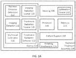
- FIG. 1Ais a block diagram of a variation of a radiation therapy assembly.
- FIG. 1Bis a schematic cross-sectional view of the radiation therapy assembly depicted in FIG. 1A .
- FIGS. 2A-2Bare illustrative cross-sectional views of a variation of a radiation therapy assembly.
- FIG. 3is an illustrative cross-sectional view of another variation of a radiation therapy assembly.
- FIG. 4is an illustrative cross-sectional view of yet another variation of a radiation therapy assembly.
- FIGS. 5A-5Bare illustrative flowcharts of a variation of a method for fault detection.
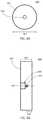
- FIGS. 6A-6Bare front and partial cross-sectional side views, respectively, of one variation of a calibration source.
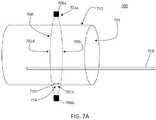
- FIG. 7Ais an illustrative schematic of one variation of a system comprising a calibration source.
- FIGS. 7B-7Care elevated perspective and top views, respectively, of one variation of mount that retains a calibration source.
- FIGS. 8A-8Care examples of histogram plots of coincident photon event counts over various coincidence time windows.
- Described hereinare radiation therapy and/or imaging systems and methods for monitoring PET detector parameters and quality metrics during a radiation therapy treatment session. These systems and methods may also be used for calibration separately from a treatment session.
- Conventional PET detector calibration monitoringis limited to time periods between patient radiation therapy treatment and/or imaging sessions. For example, a radiation point source at a known location on the system may be imaged by PET detectors on an empty couch for a QA procedure. After a QA procedure has been completed, a patient may be loaded onto the couch and undergo radiation therapy treatment and/or imaging.
- Conventional QA performed separately from a patient procedurereduces patient throughput and does not monitor the precision and/or accuracy of PET detectors during a radiation therapy treatment and/or imaging procedure.
- the systems and methods described hereinmay assist in real-time monitoring of time calibration for an array of positron emission detectors during a patient image scan and/or radiation therapy treatment.
- a PET detector that was improperly calibrated or which the calibration has changed during use and/or otherwise faultymay generate incorrect positron emission location data, which may in turn affect the quality of radiation therapy treatment and/or patient imaging.
- a change in a machine parameter or a calibration errormay quickly be identified simultaneously during a radiation therapy treatment and/or imaging session. Because patient workflow does not need to be suspended during any quality assurance or calibration, this may increase patient throughput, and may reduce incorrect radiation dose to a patient.
- a radiation therapy system as described hereinmay include an array of positron emission detectors (e.g., PET detectors) and a calibration source holder for holding a calibration source (e.g., radiation source) at a predetermined (e.g., reference) location.
- the predetermined, expected locationmay be compared to an actual computed location of the calibration source calculated by the system using the positron emission detectors. If the locations do not fall within a specified range or within a threshold parameter, then one or more of the detectors may be out of calibration and/or faulty, and the system may respond by, for example, deactivating the detectors and/or halting an imaging and/or radiation therapy treatment based on positron emission data.
- the systems and methodsmay thus provide a safety mechanism to prevent incorrect radiation dose to a patient.
- the imaging systems and methods describedmay further comprise a PET detector calibration monitoring system configured to monitor other parameters such as a temperature of the PET detector.
- Generation of a PET detector calibration fault signalmay be corroborated with the temperature of the PET detector detected by the PET detector calibration monitoring system.
- a discrepancy between the fault signal and the detected PET detector temperaturemay indicate a fault in the PET detector calibration monitoring system.
- the imaging systems and methodsmay be used with radiation therapy systems useful for high-energy photon delivery.
- a radiation treatment assemblymay be useful for emission-guided radiation therapy, where gamma rays from markers or tracers that are localized to patient tumor regions may be detected and used to direct radiation to the tumor.
- the radiation therapy systems described hereinmay comprise a movable gantry, such as a rotating gantry, with positron emission detectors and a radiation treatment source (e.g., MV X-ray source) mounted on the gantry.
- a radiation treatment sourcee.g., MV X-ray source
- the positron emission detectorsmay be mounted on the rotating gantry, and may acquire positron emission data (e.g., emissions from a PET tracer that preferentially accumulates in tumor tissue), and the radiation treatment source may deliver a radiation dose to the patient guided by the detector data and a treatment plan. In response to a determination that the positron emission detectors are out of calibration, delivery of further radiation dose may be prevented, thus increasing safety and reducing potential harm to the patient.
- positron emission datae.g., emissions from a PET tracer that preferentially accumulates in tumor tissue
- the calibration sourcefor PET detector time calibration and/or fault detection may be compact and generate radioactivity sufficient for real-time calibration while minimizing additional radiation exposure to the patient and/or operator.
- the radiation sourcemay be located between the positron emission detectors (e.g., located in a gantry housing and/or in a bore of the gantry), spatially separated from the patient, and emit enough positrons giving rise to coincident photon events to be distinguishable over noise (e.g., cosmic rays).
- the calibration sourcemay be located within or on the surface of a (stationary) housing of the rotatable gantry on a top portion and/or a bottom portion of the bore.
- the calibration sourcemay be located on the surface of a housing of the rotatable gantry and co-planar with the positron emission detectors; that is, the positron emission detectors may define an imaging plane along a cross-sectional slice of the bore and the calibration source may be located on the housing such that it is co-planar with that slice (e.g., at any circumferential location of the bore, such as at the top or 0°, or the bottom or 180°, left side or 270°, right side or 90°, etc.).
- a calibration source holdermay retain the radiation source at a location such that at least some of the photons originating from a positron annihilation event may travel along linear emission paths (e.g., LORs) that do not intersect with the patient scan or treatment region. Accordingly, calculated locations of the calibration source and patient derived from calibration source emission data and patient emission data may be spatially separated. For example, the location of the calibration source holder (and the radiation source retained within the holder) is not co-localized with the patient scan or treatment area.
- the precision and/or functionality of the positron emission detectorsmay be monitored by comparing a calculated location of the calibration source with a reference location or location range of the calibration source. For example, calibration data including coincident photon emission time offsets may be compared to reference time offsets to compute a difference between the calculated location and reference location or location range of the calibration source. A difference exceeding a threshold parameter may generate a fault signal of the PET detectors.
- fault detectionmay be performed using a stationary calibration source while the positron emission detectors are rotating.
- the calibration sourcemay comprise an annulus shape.
- the positron emission detectors and calibration sourcemay be fixed relative to each other and rotate about a bore of a gantry.
- the PET detectors and calibration sourcemay be mounted to a rotatable gantry.
- FIG. 1Aillustrates a block diagram of a radiation treatment assembly ( 100 ) for high-energy photon delivery and real-time PET detector fault detection.
- the assembly ( 100 )may include a gantry ( 110 ) including positron emission (PET) detectors ( 112 ), an imaging radiation source ( 114 ), imaging detector ( 116 ), a treatment radiation source ( 118 ), a multi-leaf collimator ( 120 ), and a treatment radiation detector ( 122 ).
- PETpositron emission
- the gantry ( 110 )may be a movable gantry such as a rotatable gantry that rotates about a longitudinal axis of the gantry ( 110 ).
- a treatment radiation source ( 118 )may be disposed on a continuously rotatable gantry to generate a radiation beam at one or more gantry angles.
- the gantry ( 110 )may comprise a ring gantry, and/or may be rotatable about a bore and have an axis of rotation that is parallel to a longitudinal axis of a bore.
- the gantry ( 110 )may comprise a C-arm shape.
- the PET detectors ( 112 )may comprise any number and configuration to detect positron emission data (e.g., a pair of 511 keV photons emitted by a positron annihilation event) generated within a patient scan or treatment region (e.g., within a bore) of the gantry ( 110 ).
- positron emission datae.g., a pair of 511 keV photons emitted by a positron annihilation event
- positron emission datae.g., a pair of 511 keV photons emitted by a positron annihilation event
- an opposing pair of PET detectorsmay detect a pair of high-energy 511 keV photons and the timing difference between the photon pair may be used to calculate the location of a photon emission origin (i.e., location of a positron annihilation event) based on time of flight (TOF) of the photons.
- the positron emission detectors ( 112 )may comprise, for example, a scintillation detector, comprising one or more of lutetium orthosilicate (LSO), lutetium-yttrium orthosilicate (LYSO), and lanthanum bromide (LaBr 3 ).
- the detectorsmay be disposed along at least a portion of a circumference of the gantry ( 110 ) and located generally opposite each other.
- the positron emission detectors ( 112 )may be located at the same location along the length of the bore as the treatment radiation source ( 118 ) and multi-leaf collimator ( 120 ) (e.g., along the same tomographic slice).
- the positron emission detectorsmay define an imaging plane along a cross-sectional slice of the bore and the treatment radiation source may be located on the gantry such that its irradiation plane or field is co-planar with that slice; that is, the treatment radiation source and the PET detectors may be co-planar (e.g., both mounted on the rotatable ring, arranged such that a beam plane of the treatment radiation source is co-planar with a detection plane of the PET detectors) or may both be located at the same longitudinal location along the bore (such that the radiation beam plane generated by the imaging radiation source may be co-planar with the radiation beam plane generated by the therapeutic radiation source).
- a rotating mechanism ( 124 )may be coupled to the gantry ( 110 ) and configured to rotate the gantry ( 110 ) from about 10 revolutions per minute (RPM) to about 70 RPM.
- the rotating mechanism ( 124 )may rotate the gantry ( 110 ) such that the detectors ( 112 ), imaging radiation source ( 114 ), imaging detector ( 116 ), treatment radiation source ( 118 ), multi-leaf collimator ( 120 ), and treatment radiation detector ( 122 ) may rotate about a rotational axis of the gantry ( 110 ).
- the detectors ( 112 )may rotate about the gantry ( 110 ) while in other variations the detectors ( 112 ) may be stationary.
- the imaging radiation source ( 114 ) and a corresponding imaging detector ( 116 )may be used to generate patient image data (e.g., CT images, MR images), and in some variations may comprise a kV source and kV detector.
- patient image datamay be used to register the patient (e.g., identify the patient's location with respect to the radiation treatment assembly components) and/or aid delivery of treatment radiation delivery to the patient.
- the treatment radiation source ( 118 )may deliver a treatment radiation dose to the patient in a bore of the gantry and may comprise, for example, a linear accelerator (linac) and a magnetron (e.g., MV X-ray source).
- linaclinear accelerator
- magnetrone.g., MV X-ray source
- the treatment radiation beammay be shaped by a beam-shaping assembly coupled to the treatment radiation source ( 118 ) to deliver a prescribed radiation dose to the ROI using a plurality of radiation beams output from a plurality of gantry angles.
- the beam assemblymay comprise a multi-leaf collimator ( 120 ) coupled to the treatment radiation source ( 118 ) and may be located in a treatment radiation beam path for shaping the treatment radiation beam delivered to the patient.
- the multi-leaf collimator ( 120 )may comprise a plurality of leaves and corresponding actuation mechanisms configured to independently move (e.g., open and close) the leaves in one or more axes (e.g., X-axis, Y-axis).
- the multi-leaf collimator ( 120 )may be a binary multi-leaf collimator.
- the treatment radiation detector ( 122 )e.g., MV detector
- the treatment radiation detectormay oppose the treatment radiation source ( 118 ).
- the treatment radiation detectormay be located along the treatment radiation beam path and may acquire treatment radiation data.
- the positron emission detectors ( 112 )may be arranged such that they are not in the treatment radiation beam path.
- the treatment radiation source ( 118 )may generate any type of ionizing radiation, for example, photon radiation (e.g., X-rays and gamma rays) and/or particle radiation (e.g., electrons, protons, neutrons, carbon ions, alpha particles, and beta particles).
- the imaging radiation source ( 114 ) and treatment radiation source ( 118 )may have separate components (e.g., linac, beam converter assembly) while in other variations the sources ( 114 , 118 ) may share one or more components (e.g., share the same beam converter assembly).
- the assembly ( 100 )may further include a housing ( 130 ) configured to hold a calibration source ( 132 ), a processor ( 140 ), memory ( 142 ), and a patient support ( 150 ).
- FIG. 1Bis a non-limiting schematic example of the radiation treatment assembly ( 100 ) depicted in FIG. 1A where calibration source ( 132 ) is not illustrated in FIG. 1B .
- the housing ( 130 )may enclose the gantry ( 110 ) and provide a barrier between the patient ( 160 ) and the gantry ( 110 ).
- the housing ( 130 )may be coupled to the gantry ( 110 ) and provided between the patient support ( 150 ) (e.g., couch) and the positron emission detectors ( 112 ).
- the gantry ( 110 )may rotate while the housing ( 130 ) remains stationary.
- the housing ( 130 )may comprise a bore ( 134 ) or opening in which the patient ( 160 ) and patient support ( 150 ) may be disposed.
- a patient ( 160 ) disposed on the patient support ( 150 )may be moved in and out of the bore ( 134 ) of the housing ( 130 ).
- the calibration source ( 132 )may be a radiation source configured to generate radiation sufficient for the detectors ( 112 ) to locate the calibration source in real-time (e.g., during a patient image scan and/or patient treatment session) without exposing the patient and/or operator to significant additional radiation.
- the calibration sourcemay comprise a positron emitting material comprising one or more isotopes such as 22-Na, 68-Ge, 68-Ga, and the like. Emitted positrons may collide with electrons in an annihilation event to generate gamma rays (e.g., a pair of diametrically opposed photons) that travel along a linear path (e.g., line of response or LOR).
- Detected photon pairsare classified as a coincidence event if they are detected by opposing positron emission detectors ( 112 ) within a pre-determined time window (e.g., coincidence time window).
- the detectorsrecord the detection location and reception time.
- a reception time difference between a pair of coincidence photonsis referred to as time of flight (TOF) and may be used to determine the origin of the positron annihilation event along the LOR.
- TOFtime of flight
- the TOF measurementexhibits uncertainty and corresponds to a timing resolution of the detectors ( 112 ).
- This uncertainty in the positron annihilation event and timing resolutionmay be represented or characterized by a probability distribution (e.g., Gaussian distribution) or related parameter, which may be further characterized by a Full Width at Half Maximum (FWHM) of the Gaussian distribution of the location derived from TOF measurement.
- a probability distributione.g., Gaussian distribution
- FWHMFull Width at Half Maximum
- the calibration source ( 132 )may comprise a radioactivity of about 1 ⁇ Ci to 300 ⁇ Ci, e.g., about 2 ⁇ Ci, about 100 ⁇ Ci. Accordingly, the calibration source ( 132 ) may emit enough positrons per second (e.g., annihilation events) for the positron emission detectors ( 112 ) to receive positron emission data allowing the processor ( 140 ) to monitor PET detector calibration (e.g., distinguish positron emissions of the calibration source ( 132 ) from the emissions of the patient ( 160 ) using time offset data).
- positrons per seconde.g., annihilation events
- the rate of positron-emission of the calibration sourcemay be known and the emission rate (and optionally, the positron annihilation rate) may be used by the controller processor to determine whether the positron emission detectors are faulty and/or calibrated properly. For example, the LOR detection rate as measured by the positron emission detectors may be compared with the known positron-emission rate of the calibration source.
- the processormay generate a notification to the user indicating that the LOR detection rate differs from the expected rate.
- the controller processormay generate an interlock signal that pauses or ceases treatment radiation delivery until the user can verify that the positron emission detectors are functioning properly and/or calibrated.
- a shape of the calibration source ( 132 )is not particularly limited and may comprise any geometric shape such as a cylinder, sphere, ring, rod, disc, line source, etc.
- a calibration sourcemay comprise a housing or enclosure and a radioactive (e.g., positron-emitting) element located within the enclosure.
- the housing or enclosuremay be disk-shaped and/or made of a non-radioactive or inert material, such as Mylar, Teflon, epoxy, and/or glass.
- the radioactive elementmay be embedded within the housing or enclosure.
- the radioactive elementmay be a pellet, bead, seed, capsule, droplet, gel, etc.
- the calibration source ( 132 )may be oriented in any direction so long as the calibration source ( 132 ) is located at the same location along the length of the gantry ( 110 ) as the PET detectors ( 112 ), i.e., co-planar with the PET detectors.
- a rod shaped or line source shaped calibration sourcemay be arranged in parallel with a longitudinal axis of the gantry ( 110 ).
- the calibration sourcemay ( 132 ) comprise a shape with a maximum dimension from about 0.25 inch to about 3 inches, e.g., about 1 inch, about 2 inches.
- the calibration source ( 132 )may comprise one or more positron-emitting capsules that each contain a quantity of positron-emitting tracer(s), where each capsule has a maximum dimension of about 2 cm. Some capsules may have a maximum dimension of no more than about 300 ⁇ m.
- a calibration sourcemay comprise a disk-shape enclosure with a diameter of about one inch, a thickness of about 0.25 inch, and a radioactive capsule with a diameter of about 0.039 inch (e.g., about 1 mm). The radioactive capsule may be embedded within an epoxy well in the enclosure, about halfway through the thickness of the disk and at the center of the disk.
- Positron-emitting capsules or calibration sourcesthat are relatively small (e.g., less than about 2 cm, less than about 1000 ⁇ m, less than about 500 ⁇ m, less than about 300 ⁇ m, etc.) may be more easily contained or isolated (to prevent unwanted contamination) and may have a relatively longer half-life (e.g., about 2 years or more, about 2.6 years).
- the calibration sourcemay comprise an array of positron-emitting capsules, arranged in a linear configuration and/or distributed radially about the bore ( 134 ).
- a calibration sourcemay be located at the top of a bore (e.g., at 0°), bottom of a bore (e.g., at 180°), or any radial or angular position about the bore (e.g., at 90°, 270°, 30°, 120°, 60°, 150°, 200°, 300°, etc.).
- a plurality of calibration sourcemay be located at radially and/or bilaterally symmetric locations about the bore (e.g., four sources at 0°, 90°, 180°, and 270°; two sources at 0° and 180°; four source at 30°, 150°, 210°, 330°, etc.).
- a calibration source ( 132 )may comprise a first positron-emitting capsule at a first location about a bore or patient area, and a second positron-emitting capsule at a second location across from (e.g., about 180 degrees from) the first positron-emitting capsule.
- a first positron-emitting capsulemay be located at a first end of a first array of PET detectors, a second positron-emitting capsule located at a second end of the first array of PET detectors, a third positron-emitting capsule located at a first end of a second array of PET detectors, and a fourth positron-emitting capsule located at a second end of the second array of PET detectors.
- the positron-emitting capsules of a calibration sourcemay be located outside of a patient area or the bore of a gantry.
- the calibration source ( 132 ) or positron-emitting capsulemay comprise a radioactive portion and a non-radioactive housing enclosing the radioactive portion.
- the non-radioactive housingmay be disc shaped and a radioactive portion may be spherical and located at a center of the disc.
- a ring shaped radiation portionmay be disposed in a disc shaped non-radioactive housing.
- the non-radioactive housingmay be cylindrical and a radioactive portion may be disposed in spaced apart wells located, for example, at the ends of the cylinder.
- the patient support ( 150 )may comprise a support surface and a base (not shown) for control of positioning of a patient in the assembly ( 100 ).
- the basemay be fixed to the ground and the support surface may be coupled to the base such that the support surface may move in and out of a bore of the gantry ( 110 ).
- the patientmay be disposed on the support surface to be imaged and/or treated by the assembly ( 100 ) (e.g., the patient lying flat on the patient support ( 150 )).
- the processor ( 140 )may incorporate data received from the memory ( 142 ) and positron emission detectors ( 112 ) to compute a location of the calibration source ( 132 ) based on detected emission data. Based on the calculated location, positron emission data may be classified as originating from one of the calibration source and the patient scan region.
- the memory ( 142 )may further store instructions to cause the processor ( 140 ) to execute modules, processes and/or functions associated with the system ( 100 ), such as fault detection and safety (e.g., deactivation of one or more system components, stopping radiation therapy treatment, outputting system status, etc.).
- the memory ( 142 )may be configured to store location data of the calibration source ( 132 ), one or more threshold parameters, a patient treatment plan, one or more spatial filters, positron emission data (e.g., positron emission path data), calibration data, patient data, and operator input.
- location data of the calibration source ( 132 )one or more threshold parameters, a patient treatment plan, one or more spatial filters, positron emission data (e.g., positron emission path data), calibration data, patient data, and operator input.
- the Memory ( 142 )may store a location of the radioactive source held in the radioactive source holder.
- the processor ( 140 )may be any suitable processing device configured to run and/or execute a set of instructions or code.
- the processormay be, for example, a general purpose processor, a Field Programmable Gate Array (FPGA), an Application Specific Integrated Circuit (ASIC), a Digital Signal Processor (DSP), and/or the like.
- the processormay be configured to run and/or execute application processes and/or other modules, processes and/or functions associated with the system and/or a network associated therewith (not shown).
- MOSFETmetal-oxide semiconductor field-effect transistor
- CMOScomplementary metal-oxide semiconductor
- ECLemitter-coupled logic
- polymer technologiese.g., silicon-conjugated polymer and metal-conjugated polymer-metal structures
- mixed analog and digitaland/or the like.
- the memory ( 142 )may include a database (not shown) and may be, for example, a random access memory (RAM), dynamic random access memory (DRAM), static random access memory (SRAM), a memory buffer, a hard disk drive, optical disc, magnetic tape, an erasable programmable read-only memory (EPROM), an electrically erasable read-only memory (EEPROM), a read-only memory (ROM), Flash memory, solid state drive (SSD), memory card, etc.
- the memory ( 142 )may store instructions to cause the processor ( 140 ) to execute modules, processes and/or functions associated with the system ( 100 ), such as fault detection.
- the system ( 100 )may be in communication with other devices (not shown) via, for example, one or more networks, each of which may be any type of network.
- a wireless networkmay refer to any type of digital network that is not connected by cables of any kind. Examples of wireless communication in a wireless network include, but are not limited to cellular, radio, and microwave communication. However, a wireless network may connect to a wireline network in order to interface with the Internet, other carrier voice and data networks, business networks, and personal networks.
- a wireline networkis typically carried over copper twisted pair, coaxial cable or fiber optic cables.
- networkrefers to any combination of combined wireless, wireline, public and private data networks that are typically interconnected through the Internet, to provide a unified networking and information access solution.
- the systemmay be configured to provide not only patient diagnostic or therapeutic data, but also machine calibration data (e.g., calibration data) and QC data to the patient's electronic healthcare record and/or to electronic record systems used by accreditation agencies, such as the American College of Radiology, the Joint Commission, the UK Accreditation Services (UKAS), and the European Association of Nuclear Medicine's EARL program, for example.
- machine calibration datae.g., calibration data
- QC datae.g., calibration data
- accreditation agenciessuch as the American College of Radiology, the Joint Commission, the UK Accreditation Services (UKAS), and the European Association of Nuclear Medicine's EARL program, for example.
- a calibration source of a radiation therapy assemblymay comprise a number of configurations and/or locations relative to the assembly.
- a calibration sourcemay be a radiation source comprising a substance that emits positrons within a field of view of the PET detectors sufficient to monitor a detector time calibration while minimizing dose to the patient.
- the radioactive source described with respect to FIGS. 2-4may emit photons with an energy of 511 keV for each positron annihilation event.
- the radioactive source of a calibration sourcemay comprise a substance that emits radiation having a different energy level.
- the calibration sourcesmay be located on a radiation treatment assembly such that at least some lines of response originating from the calibration source do not intersect a patient and/or patient support disposed in a bore of the gantry. That is to say, the calibration source may intersect at least one line provided between opposing positron emission detectors and which are unobstructed by a patient and/or patient support (although the line may pass through other structures such as the gantry housing). As an illustrative example, the calibration source may be disposed along a housing coupled to the gantry at a location at least about 20 cm above the patient support. Spatial separation between the calibration source and the patient may reduce errors in a calculated location of the calibration source and the patient.
- a fault signal for one or more positron emission detectorsmay be generated using the positron emission data of the calibration source. The system may respond appropriately to the fault signal (e.g., output a detector status, deactivate faulty detectors, and/or stop treatment).
- calibration radiation source ( 600 )may comprise a disk-shaped enclosure or housing ( 602 ) and a positron-emitting element ( 604 ) located within the enclosure, at the center of the disk.
- the enclosure ( 602 )may be made of a non-radioactive material and may have a well ( 606 ) within which the positron-emitting element ( 604 ) may be located.
- the enclosure ( 602 )may be made as a solid disk, a well ( 606 ) may be created within the disk (e.g., optionally, located on the center of the disk as represented by the dotted line ( 607 )), the positron-emitting element ( 604 ) may be inserted into the well ( 606 ), and the well may then be filled with a non-radioactive material, such as an epoxy.
- the diameter ( 601 ) of the enclosure ( 602 )may be from about 0.25 inch to about 3 inch, e.g., about 1 inch, about 2 inches.
- the thickness ( 603 )may be from about 0.1 inch to about 0.5 inch, e.g., about 0.25 inch.
- the size of the positron-emitting elementmay be from about 150 ⁇ m to about 500 ⁇ m, e.g., about 200 ⁇ m, about 250 ⁇ m, about 300 ⁇ m, etc.
- the positron-emitting element ( 604 )may be inserted or embedded such that it is halfway between the thickness of the disk.
- the positron-emitting element ( 604 )may be located at a distance ( 608 ) from one side surface of the enclosure ( 602 ), where the distance ( 608 ) may be from about 0.01 inch to about 0.4 inch, e.g., about 0.12 inch, about 0.2 inch, etc.
- a treatment radiation sourcee.g., MV X-ray source
- FIGS. 2-4may be imaging systems that do not have a treatment radiation source, or they may be radiation treatment systems with a treatment radiation source that has been omitted for ease of explanation.
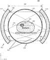
- FIGS. 2A-2Bare cross-sectional schematic views of a radiation treatment assembly ( 200 ) including a rotatable gantry ( 210 ) having mounted thereon a first array of positron emission detectors ( 212 ) and a second array of positron emission detectors ( 214 ) opposing the first array of detectors ( 212 ).
- Each array of detectors ( 212 , 214 )may comprise a plurality of positron emission detectors.
- a housing ( 220 )may couple to the gantry ( 210 ) (e.g., the housing ( 220 ) may be disposed over the gantry ( 210 )), and the housing ( 220 ) may comprise a bore ( 224 ) in which a patient support ( 250 ) may be disposed.
- Each positron emission detectorhas an imaging field of view that is the angle through which that detector is sensitive to positron emissions.
- a patient scan region ( 242 )e.g., patient imaging field of view
- the contours of the patient ( 240 ) and/or the patient support ( 250 ) detectable by the positron emission detectorsmay define a patient scan region ( 242 ).
- the patient support ( 250 )may comprise a movable support surface on which the patient ( 240 ) may be disposed.
- the movable support surfacemay be coupled to a base (not shown).
- the housing ( 220 )may comprise a stationary calibration source holder ( 222 ) and/or calibration source ( 230 ) (e.g., radiation source) spaced away from the patient scan region ( 242 ) within the bore ( 224 ) and within a field of view of the positron emission detectors ( 212 , 214 ).
- the calibration source holder ( 222 ) and/or calibration source ( 230 )may be located on a surface of the housing ( 220 ) (e.g., facing the patient support ( 250 )).
- the assembly ( 200 )may comprise a single calibration source holder ( 222 ) and calibration source ( 230 ) where FIGS.
- 2A-2Billustrate two calibration source holders ( 222 ) and calibration sources ( 230 ) for ease of explanation, however, it should be understood that in some variations, there may be a single calibration source holder and calibration source at either of the locations depicted in the figures (e.g., only at the top or only at the bottom portion of the bore), or additional calibration source holders and calibration sources at additional locations around the bore.
- the calibration source holder ( 222 )may be configured to hold any of the calibration sources described herein (e.g., a positron emitting radiation source).
- the calibration source holder ( 222 )may securely hold the calibration source ( 230 ) at a desired location (e.g., reference location or location range) using any known means, including but not limited to adhesives, a closure mechanism, and an interference fit or mechanical interfit between the calibration source holder ( 222 ) and calibration source ( 230 ).
- a closure mechanismmay include a cap, cover, lid, plug, latch, lock, threaded ring, and combinations thereof.
- the calibration source holder ( 222 )may allow the calibration source ( 230 ) to be removably coupled to the housing ( 220 ) such that the calibration source ( 230 ) may be replaced after its useful lifespan.
- the calibration source holder ( 222 )may be disposed along the surface of the housing ( 220 ) at a location furthest from the patient scan region ( 242 ). In one example, the calibration source holder ( 222 ) may be disposed at a top, center location of the housing ( 220 ) (e.g., where the calibration source holder ( 222 ) is disposed). This location may be the furthest away from the patient ( 240 ) and therefore provide the least amount of additional dose from the calibration source ( 230 ) to the patient ( 240 ).
- a patient support ( 250 )may be disposed below a rotational axis of the gantry ( 210 ) (e.g., mechanical isocenter axis) such that the patient ( 240 ) on the patient support ( 250 ) intersects a rotational axis of the gantry ( 210 ). Therefore, a distance from a top, center location of the housing ( 220 ) to the patient ( 240 ) may be greater than the distance of any other point along the surface of the housing ( 220 ).
- the calibration source holder ( 222 )may be disposed along the surface of the housing ( 220 ) above or below the support surface of the patient support ( 250 ).
- the calibration source holder ( 222 )may be disposed above a horizontal plane of the patient support ( 250 ) and/or perpendicular to the patient support ( 250 ).
- the calibration source holder ( 222 )may be disposed above the patient scan region ( 242 ).
- the calibration source holdermay be disposed at least about 20 cm above the support surface of the patient support ( 250 ).
- the calibration source holder ( 222 ) disposed along the surface of the housing ( 220 )may be above the highest point of the patient ( 240 ).
- the calibration source holder ( 222 )may be disposed below a horizontal plane of the patient support ( 250 ) and/or perpendicular to the patient support ( 250 ).
- the calibration source holder ( 222 )may be disposed at a bottom, center location of the bore ( 224 ).
- FIG. 2Billustrates the first array and second array of detectors ( 212 , 214 ) at a second position rotated relative to the detectors ( 212 , 214 ) at a first position in FIG. 2A .
- the positron emission detectors ( 212 , 214 )detect photon pairs emitted by the calibration source ( 230 ) and patient ( 240 ). The photon pair travels along a line of response ( 232 ) originating from the calibration source ( 230 ) and extending towards the first array of detectors ( 212 ) and the second array of detectors ( 214 ).
- the calibration source LORs ( 232 )are non-intersecting with the patient scan region ( 242 ) (e.g., patient imaging field of view of the detectors including patient ( 240 ) and/or patient support ( 250 )) such that at least some of the calibration source LORs ( 232 ) are spatially separated from patient lines of response ( 234 ) emitted from the patient ( 240 ). Consequently, the calibration source holder ( 222 ) is located for a calibration source ( 230 ) to form at least one LOR ( 232 ) unobstructed by the patient ( 240 ) and/or the patient support ( 250 ).
- the gantry ( 210 )may further comprise a treatment radiation source and treatment detector between the first array and second array of detectors ( 212 , 214 ) having a treatment field of view ( 260 ).
- a stationary calibration radiation source holdermay comprise a groove or recess within an internal wall of the bore, or may be a groove or recess within a structure that may be attached to an internal wall of the bore.
- a covermay be removably disposed over the groove or recess to retain the calibration source within the groove or recess, and engaged over the groove or recess via any attachment mechanism (e.g., snap-fit, friction-fit, screw-fit, with or without the use of additional one or more screws or fasteners).
- the optional covermay be removed.
- FIG. 7Adepicts one variation of a radiation treatment assembly or imaging system ( 700 ) comprising a bore ( 702 ) and a patient platform ( 704 ) movable along a longitudinal axis of the bore ( 702 ).
- the system ( 700 )may comprise a rotatable gantry (not shown) that may have an axis of rotation that is collinear with the central axis of the bore ( 702 ), and a first array of positron emission detectors ( 706 a ) mounted on the gantry and a second array of positron emission detectors ( 706 b ) mounted on the gantry across from (i.e., opposite to) the first array of positron emission detectors ( 706 a ).
- the first and second array of positron emission detectorsmay be located along a plane or slice ( 708 ) of the bore (e.g., orthogonal to the longitudinal axis of the bore).
- the system ( 700 )is a radiation treatment assembly comprising a treatment radiation source mounted on the rotatable gantry between the first and second positron emission detector arrays
- the treatment beam planemay be co-planar with the positron emission detector slice ( 708 ).
- a calibration radiation source ( 710 ) and the calibration radiation source holder ( 714 )may be located within the bore ( 702 ), at a bottom location ( 701 b ) of the bore, below the patient support ( 704 ).
- calibration radiation sources and/or holdersmay be located at one or more circumferential locations about bore (e.g., at 701 a or 0°, at 701 b or 180°, at 701 c or 90°, and/or at 701 d or 270°, above the patient support, etc.).
- the calibration source holder ( 714 )may be a groove or recess within an internal surface of the bore ( 702 ), with or without a cover, as described above.
- a calibration source holder located above the bottom region of a boremay comprise a cover to prevent the calibration source from falling out, while a calibration source holder located at the bottom of the bore may not have a cover.
- the calibration source holder ( 714 )may also have a corresponding disk-shape.
- the calibration radiation source holdermay be integral with, and/or a part of, a housing of other components of the system.
- any of the systems described hereinmay comprise one or more optical cameras and/or light sources within a bore, and comprise a camera and/or lighting mount attached to the internal wall of the bore.
- the camera and/or lighting mountmay comprise a groove or recess that is configured to be retain a calibration source (i.e., configured to be a calibration radiation source).
- the camera and/or lighting mountmay comprise a recess that has a size and shape that corresponds with the size and shape of a calibration source and an optional calibration source engagement structure, such as a cover (such as any of the covers described above), clasp, and/or magnetic source holder.
- the calibration radiation source holder and/or mountmay have one or more alignment structures, such as one or more grooves and/or protrusions that may help to retain the calibration radiation source in precise alignment with the other components of the radiation treatment assembly.
- the holder and/or mountmay have one or more protrusions that restrict motion of the calibration source in a first direction (e.g., IEC-Y) and/or one or more additional protrusions that restriction motion of the calibration source in a second direction (e.g., IEC-X).
- one or more protrusionsmay include a wall portion of a camera and/or lighting mount.
- a groove or slot within which the calibration source may be seatedmay restrict motion of the calibration source.
- the holder and/or mountmay be centered or aligned with an isocenter of the system (e.g., along a central longitudinal axis of the bore).
- FIGS. 7B-7Cdepict an elevated perspective view and a top view, respectively, of a lighting mount that may be attached to an internal surface or wall of the bore, the lighting mount comprising a calibration source holder.
- One or more light sourcessuch as LEDs, may be attached to the internal surface of the bore via the lighting mount.
- a lighting coverhaving a corresponding shape and size (e.g., footprint) as the light mount may be disposed over the mount.
- the lighting mount ( 700 )may comprise a walled tray or enclosure ( 702 ) comprising one or more bore attachment structures ( 704 ), a calibration source holder alignment protrusion ( 706 ) and a calibration source receiving portion or holder ( 708 ).
- the calibration source holder or receiving portion ( 708 ) for a calibration source shaped as a circular diskmay comprise a circular recess that has a diameter that is slightly larger than the diameter of the circular disk so that the calibration source may be retained within the recess.
- the bore attachment structure ( 704 )may comprise a bracket that engages a corresponding notch on the internal wall of the bore, and/or may comprise structures for a screw-fit or any other such engagement with the bore.
- the lighting mount ( 720 )may also comprise one or more cover attachment structures ( 710 ), which may comprise a clip or clamp that may be used to retain or grasp a corresponding protrusion, flap, or tongue of an optional lighting cover (not shown). In the variation depicted in FIGS.
- the lighting mount ( 720 )may have an elongated oblong shape, where the calibration source holder or receiving portion ( 706 ) may be located at one end of the elongated shape.
- the walled enclosure ( 702 )may comprise a main oblong portion where the one or more light sources may be attached and a narrow extension to the main oblong portion where the calibration source holder or receiving portion may be located. This may help to segregate the calibration radiation source from the light sources, which may help reduce radiation damage to the light sources.
- a plurality of calibration radiation sources and/or holdersmay be distributed circumferentially about the bore, at a plurality of bore angles (e.g., bore angle locations 701 a - 701 d , as well as angles between).
- FIG. 3is a cross-sectional schematic view of a radiation treatment assembly ( 300 ) that may be configured to provide real-time calibration monitoring of PET detectors and include a gantry ( 310 ) having a first array of positron emission detectors ( 312 ) and a second array of positron emission detectors ( 314 ) opposing the first array of detectors ( 312 ).
- Each array of detectors ( 312 , 314 )may comprise a plurality of positron emission detectors and mounted to a movable or stationary gantry. Accordingly, the PET detector arrays may rotate or be stationary.
- a housing ( 320 )may couple to the gantry ( 310 ) (e.g., the housing ( 320 ) may be disposed over the gantry ( 310 )), and the housing ( 320 ) may comprise a bore ( 322 ) in which a patient ( 340 ) and a patient support ( 350 ) may be disposed.
- a patient scan region ( 342 )(e.g., patient imaging field of view) may be represented by a volume of the patient ( 340 ) and/or patient support ( 350 ). That is, the contours of the patient ( 340 ) and/or the patient support ( 350 ) detectable by the positron emission detectors may define a patient scan region ( 342 ).
- the patient support ( 350 )may comprise a movable support surface on which the patient ( 340 ) may be disposed and the movable support surface may be coupled to a base (not shown).
- the housing ( 320 )may further comprise an annular calibration source ( 330 ) (e.g., annular radiation source) about at least a portion of the bore ( 322 ).
- the radioactivity level of an annular calibration sourcemay be similar to the radioactivity level of any of the calibration sources described herein, e.g., about 1 ⁇ Ci to 300 ⁇ Ci, e.g., about 2 ⁇ Ci, about 100 ⁇ Ci.
- the annular calibration source ( 330 )may be stationary and located below a surface of the housing ( 320 ) and/or may comprise the surface of the housing ( 320 ).
- the annular calibration source ( 330 )may be located between the first array and second array of detectors ( 312 , 314 ).
- the annular calibration source ( 330 )may comprise a continuous annulus. Regardless of the configuration of the positron emission detectors ( 312 , 314 ) (e.g., rotatable or stationary), the annular calibration source ( 330 ) may be located within a field of view of the positron emission detectors ( 312 , 314 ).
- FIG. 3illustrates an annular calibration source LOR ( 332 ) intersecting the annular calibration source ( 330 ) at a first location ( 334 ) and a second location ( 336 ).
- the LOR ( 332 )may be unobstructed by the patient ( 340 ) and/or the patient support ( 350 ).
- the positron annihilation event corresponding to the LOR ( 332 )may originate from either the first or second location ( 334 , 334 ) of the annular calibration source ( 330 ).
- a TOF PET systemmay use a reception time difference (e.g., timing distributions) of the coincidence photons detected by the first array of detectors ( 312 ) and second array of detectors ( 314 ) to classify the first location ( 334 ) or second location ( 336 ) as the origin of the positron annihilation event.
- a reception time differencee.g., timing distributions
- the timing distributions of the first and second locations of the annular calibration source ( 330 )are different from timing distributions of positron emissions originating from a patient scan region ( 342 ) of the patient ( 340 ) because the annular calibration source ( 330 ) is located closer to the detectors ( 312 , 314 ) than the patient ( 340 ), and therefore has a larger positron emission reception time difference than that of the emissions from the patient located closer to a center of the bore.
- the first and second arrays of positron emission detectorsmay generate positron emission data from the annular calibration source ( 330 ) and the patient ( 340 ).
- a processor of the assembly ( 300 )may distinguish the positron emission data from the patient ( 340 ) and from the annular calibration source ( 330 ).
- the assembly ( 300 )may concurrently classify (e.g., locate) the positron emission data from the annular calibration source ( 330 ) and the patient scan region ( 342 ) within the bore ( 322 ) using the reception times of the received photon pairs (e.g., using TOF data).
- a spatial filtermay then be applied to the calculated locations, as discussed in more detail below.
- the annular calibration source ( 330 )may comprise one or more portions (e.g., an upper portion disposed above a plane of the support surface ( 350 ) and a lower portion disposed below the plane of the support surface ( 350 )). In some of these variations, an upper portion of the annular calibration source ( 330 ) may be disposed above the patient scan region ( 342 ). For example, the annular calibration source ( 330 ) may be disposed at least about 20 cm above the support surface of the patient support ( 350 ) and/or above the highest point of the patient scan region ( 342 ) (e.g., above a plane intersecting the highest point of the patient scan region ( 342 ) and parallel to the patient support ( 350 )).
- annular calibration source ( 330 )may be disposed below a horizontal plane of the patient support ( 350 ).
- These exemplary annular calibration source ( 330 ) configurationsmay provide less additional dose to a patient relative to an annular calibration source ( 330 ) that encircles the patient ( 340 ) entirely.
- the annular calibration source ( 330 )may be attached to the housing ( 320 ), and the housing ( 320 ) may be removably attached to the gantry ( 310 ), thereby allowing the housing ( 320 ) and annular calibration source ( 330 ) to be replaced after its useful lifespan.
- the annular calibration source ( 330 )may comprise a thickness of about 0.10 mm to about 2.0 mm and a width of about 0.10 mm to about 5 cm. In some variations, the annular calibration source ( 330 ) may comprise a plurality of portions with each portion having different shapes and dimensions.
- FIG. 4is a cross-sectional schematic view of an assembly ( 400 ) that may be configured to provide real-time calibration monitoring of PET detectors and include one or more calibration source holders ( 408 ).
- the radiation treatment assembly ( 400 )may include a rotatable gantry ( 410 ) having mounted thereon a first array of positron emission detectors ( 412 ) and a second array of positron emission detectors ( 414 ) opposing the first array of detectors ( 412 ).
- Each array of detectors ( 412 , 414 )may comprise a plurality of positron emission detectors.
- one or more calibration source holders ( 408 )may be coupled to the gantry ( 410 ) such that the one or more calibration source holders ( 408 ) are fixed relative to the first array and the second array of detectors ( 412 , 414 ). In other words, the positron emission detectors ( 412 , 414 ) and calibration source holders ( 408 ) rotate together.
- a housing ( 420 )may couple to the gantry ( 410 ) (e.g., the housing ( 420 ) may be disposed over the gantry ( 210 )), and the housing ( 220 ) may comprise a bore ( 422 ) in which a patient ( 440 ) and a patient support ( 450 ) may be disposed.
- a patient scan region ( 442 )e.g., patient imaging field of view
- the patient support ( 450 )may comprise a movable support surface on which the patient ( 440 ) may be disposed and the movable support surface may be coupled to a base (not shown).
- the one or more calibration source holders ( 408 ) and/or calibration sources ( 430 )may be spaced away from the patient scan region ( 442 ) within the bore ( 422 ) and within a field of view of the positron emission detectors ( 412 , 414 ).
- one or more calibration source holders ( 408 ) and/or calibration sources ( 430 )may be coupled to the detectors ( 412 , 414 ) and movable relative to the housing ( 420 ) (e.g., rotate about the housing ( 420 )).
- the one or more calibration source holders ( 408 ) and/or calibration sources ( 430 )may be disposed along the detectors ( 412 , 414 ) on a side facing an opposing detector ( 414 , 412 ).
- At least some of the lines of response ( 432 ) originating from one or more calibration sources ( 430 )extend toward the first array of detectors ( 412 ) and the second array of detectors ( 414 ).
- at least some of the calibration source LORs ( 432 )are non-intersecting with the patient scan region ( 442 ) and/or patient support ( 450 ).
- LORs ( 434 )may be emitted from an ROI ( 444 ) of the patient ( 440 ).
- LORs ( 432 ) emitted by the calibration sources ( 430 )may be detected by the positron emission detectors ( 412 , 414 ).
- each calibration source holder ( 408 )is located for a calibration source ( 430 ) such that at least one LOR ( 432 ) emitted by the calibration source ( 430 ) is unobstructed by the patient ( 440 ) and/or the patient support ( 450 ).
- one or more calibration source holders ( 408 )may be located along a line non-intersecting with a patient imaging field of view (e.g., patient scan region ( 442 )) of the detectors ( 412 , 414 ), and the line may extend from the first array of detectors ( 412 ) to the second array of detectors ( 414 ).
- the patient imaging field of viewmay comprise a volume located between the first array and second array of detectors.
- one or more calibration source holders ( 430 )may be fixed relative to the first array and the second array of detectors ( 412 , 414 ) and located with at least one line of sight unobstructed by a patient ( 440 ) and/or patient support ( 450 ), although the line may pass through other structures such as the housing ( 420 ).
- the assembly ( 400 )may comprise a single calibration source holder ( 408 ) where the exemplary FIG. 4 illustrates four calibration source holders ( 408 ) and calibration sources ( 430 ).
- the calibration source holder ( 408 )may be configured to hold the calibration source ( 430 ) in a manner as described in detail above.
- the calibration source holder ( 408 )may allow the calibration source ( 430 ) to be removably coupled to the detectors ( 412 , 414 ) such that the calibration source ( 430 ) may be replaced after its useful lifespan.
- the gantry ( 410 )may further comprise a treatment radiation source and treatment detector between the first array and second array of detectors ( 412 , 414 ) having a treatment field of view ( 460 ).
- the systemmay comprise first and second arrays of PET detectors mounted on a rotatable gantry, where the PET detectors are configured to receive positron emissions from a calibration source (e.g., radiation source) and/or a patient to generate calibration data and/or to extract positron emission data representing positron emission activity originating from the calibration radiation source.
- calibration datamay comprise data extracted from the acquired positron emission data that pertains to the calibration source, and in some variations, may also include any data quantity calculated based upon acquired positron emission data, such as calculated location data of the calibration source and/or patient.
- positron emissions from the calibration sourcemay be distinguished from the positron emissions from a patient by identifying the LORs that do not cross or intersect with a patient scan or treatment region of the bore.
- Examples of calibration datamay include spatial resolution data, temporal resolution data, energy sensitivity data and/or energy precision data, and/or the ability to accurately determine the location of the calibration radiation source.
- calibration datamay include the number of detected LORs that intersect with the location of a stationary calibration source over one or more gantry rotations, and/or the energy level(s) of the detected LORs (i.e., the coincident photon events) over one or more gantry rotations, and/or the number of detected LORs or coincident photon events detected within coincidence time windows having different window widths. If the calibration data exceeds a threshold parameter, such as when the calibration data does not sufficiently correspond to a reference location or location range of the calibration source for a predetermined time period, a fault signal may be generated.
- calibration data deviationsmay include detecting a greater (or lesser) number of LORs that intersect with the location of the stationary calibration source than is expected (based on the known and specified positron emission rate and/or radioactivity of the calibration source), detecting LORs having energy level(s) that deviate from a 511 keV peak, and/or not detecting a threshold number of LORs or coincident photon events with specific time difference values (e.g., time differences that correspond to one or more of PET detectors being close to the calibration source while other PET detectors are located far from the calibration source) and/or within a first coincidence time window centered around a time difference value of 0 ns (i.e., the number of “true” coincident photon events).
- a fault signalmay be generated.
- the systemmay respond in one or more ways to the fault signal including performing additional diagnostics on the detectors and/or assemblies (e.g., gantry motion sensor and/or encoder diagnostics/characterization, calibration radiation source diagnostics/characterization, etc.), deactivating one or more detectors, stopping radiation therapy treatment, and/or recalibrating the detectors. It should be appreciated that any of the systems described herein may be used to determine a fault in the detectors using the methods discussed below.
- FIGS. 5A-5Billustrate a fault detection method ( 500 ) using any of the assemblies ( 100 , 200 , 300 , 400 ) discussed above.
- a radiation treatment assemblymay comprise a gantry comprising a plurality of positron emission detectors, an imaging radiation source, a treatment radiation source, and one or more calibration sources provided between the detectors.
- one or more calibration sourcesmay be disposed in a housing within a field of view of the positron emission detectors and located at the same location along the length of the assembly as the positron emission detectors.
- the positron emission detectors and one or more calibration sourcesmay be configured in various combinations of stationary and rotatable elements, as discussed in detail above.
- a patientPrior to an imaging and/or radiation therapy procedure, a patient may be administered a radioisotope for uptake into the body.
- the patientmay lay on a patient support (e.g., couch) and be moved into a bore of a gantry such that a ROI of the patient (e.g., one or more tumors or lesions) may be within a field of view of the positron emission detectors.
- Both the patient and the calibration sourcemay be provided between the detectors with the calibration source spaced away from the patient.
- the patientmay be disposed within a bore of the assembly and the calibration source held by a calibration source holder on a surface of the housing.
- An array of positron emission detectorsmay be activated to detect positron emissions emitted within a detector field of view ( 502 ).
- the positron emission detectorsmay be mounted on a rotatable gantry where the gantry is configured to rotate about a bore of the gantry while in other variations the detectors may be mounted on a stationary gantry.
- the positron emission detectorsmay receive positron emission data from any positron emission source provided between the detectors.
- positron emission data from the patient and the calibration sourcemay be continuously received and processed ( 504 ).
- the positron emission datamay include TOF data such as a detector reception location and reception time of the photon by that detector.
- the patientmay be treated by receiving a treatment radiation dose from the treatment radiation source ( 506 ). That is to say, positron emission data may be received during a treatment session. While positron emission data may be acquired during a treatment session, the timing of the positron emission data acquisition may be staggered with respect to the timing of the treatment beam pulses.
- positron emission datamay be received by the positron emission detectors at predetermined time intervals between treatment radiation beamlets.
- the patientmay receive radiation therapy treatment from treatment modalities including, for example, emission-guided radiation therapy (EGRT), stereotactic body radiation therapy (SBRT), and intensity modulated radiation therapy (IMRT). Additionally or alternatively, the patient may be concurrently imaged by an imaging radiation source.
- the patient treatment and/or imaging step ( 506 )may be performed in parallel (e.g., within a predetermined time period) with one or more of the steps of FIGS. 5A-5B .
- the method ( 500 )may perform one or more imaging and treatment steps ( 506 ) with the reception of the positron emission data ( 504 ) and/or generation of calibration data ( 516 ) with at least some temporal overlap.
- the step of receiving positron emission data from the calibration source and from the patient ( 504 )may be performed concurrently with generating a fault signal ( 524 ).
- An annihilation event comprising a photon pairmay be detected by opposing positron emission detectors and define an LOR.
- LORs of the positron emission datamay be classified by a processor to one or more calculated locations or location ranges of the calibration source and the patient ( 508 ).
- calculated positron emission locationsmay be classified by a processor using reference time offsets or a spatial filter ( 509 ).
- the LORsare classified using positron emission data received within a coincidence time window of between about 6 nanoseconds and 10 nanoseconds.
- the trajectory of a photon pair emitted by a positron annihilation eventdefines a LOR (e.g., a positron emission path).
- the origin of the annihilation eventis at point located along the LOR and may be located using a difference in photon reception times (i.e., a time difference or time offset).
- a difference in reception times between the photonscorresponds to a distance traveled by the photons along the LOR from the annihilation event. For example, if each photon of an annihilation event arrives at a respective detector at the same time, then the photons have traveled an equal distance such that the annihilation event originates at a midpoint of the LOR.
- a positron emission (e.g., annihilation event) origin location corresponding to the calibration source and/or the patientmay be calculated by a processor using TOF data (e.g., reception time difference of the pair of photons), LOR, and reference time offsets ( 510 ).
- TOF datae.g., reception time difference of the pair of photons
- LORLOR
- reference time offsets510
- positron emission path datamay be classified as originating from a calibration source (e.g., stationary radiation source) using a difference between a reception time of the pair of photons with a time threshold parameter range (e.g., time difference range) corresponding to the calibration source.
- Positron emission path data outside the time threshold parameter rangemay be classified as noise or as originating from the patient.
- the positron emission detectormay comprise a coincidence time resolution of at least about 300 picoseconds (ps) (FWHM) corresponding to a positional uncertainty of about 4.5 cm (FWHM) along
- the calibration sourcemay be distinguished from the positron emission data by comparing the difference in reception times (e.g., time difference or time offset) of a photon pair to a reference time offset corresponding to a location of the calibration source.
- a look-up table (LUT) of reference time offsetsmay be stored in memory and compared to positron emission data.
- a stationary calibration sourcemay be located on a housing of a rotatable gantry relative to the PET detectors rotating about the patient scan or treatment region such that the time offset (e.g., time difference) is about 2.5 ns when PET detectors are located at specified gantry angles about the patient scan or treatment region.
- the time difference or time offset value corresponding to coincident photon originating from the calibration sourcemay have different time difference values.
- a fault signalmay be generated if the number of coincident photon events detected for time offsets other than 2.5 ns (“random” coincident photon events) is the same as, or greater than, the number of coincident photon events detected for a time offset of 2.5 ns (“true” coincident photon events).
- the coincident photon events originating from the calibration sourcemay be distinguished from the coincident photon events originating from a PET-avid region in a patient using the spatial/sinogram filters described herein, optionally in combination with temporal filters that select for events with particular temporal characteristics (e.g., certain time difference values between the detection times of the two photons in a coincident event).
- a passing criteria or thresholdmay be a ratio of the number of true coincident photon events to the number of random coincident photon events (true-to-random ratio value), where the value of the ratio is greater than or equal to one.
- the time difference or offset valuemay be any value (e.g., any value other than 2.5 ns).
- the width of the coincidence time window for detecting coincident photon events from either or both the calibration source(s) and/or PET-avid patient or phantom within the boremay be adjusted (e.g., expanded or narrowed relative to the examples described herein) as appropriate so that these coincident photon events may be extracted from the PET detector data. While the coincidence time window width may vary, the coincidence time window width may be centered around about 0 ns.
- a distance of the detector to the calibration sourcemay vary as a function of gantry angle as the PET detectors rotate about a bore of the gantry. From a positron emission detector point-of-view (e.g., PET detector reference frame), the position of the PET detector is fixed as the calibration source rotates at a gantry angle theta ( ⁇ ) defined relative to a reference direction.
- a positron emission detector point-of-viewe.g., PET detector reference frame
- the location of the detectormay be defined by coordinates ⁇ x,y> where the X-axis corresponds to a horizontal axis plane (e.g., parallel to the ground and/or a patient support) and the Y-axis corresponds to a vertical plane perpendicular to the horizontal plane.
- the location of the calibration sourcemay be defined as (r cos ⁇ , r sin ⁇ ) where r represents a radius from a reference point (e.g., origin of the detector ⁇ x,y>) and ⁇ is an angle from the reference direction.
- a location of a photon pair (e.g., first and second photons) detected by respective detectorsmay be defined as ⁇ x 1 ,y 1 > and ⁇ x 2 ,y 2 >, respectively.
- the first and second photonseach travel at the speed of light (c) from the annihilation point to opposing positron emission detectors.
- a difference in reception timei.e., a time difference or time offset
- ⁇ t2*( d 1 ⁇ d 2 )/ c
- a reference time offsetmay be compared to a corresponding detected photon pair time offset and a threshold parameter to generate a fault signal, as described in more detail below.
- an assemblymay comprise a rotatable gantry having mounted thereon positron emission detectors and a stationary housing coupled to a calibration source such as the annular radiation source illustrated in FIG. 3 .
- a calibration sourcesuch as the annular radiation source illustrated in FIG. 3 .
- Each LOR of the stationary calibration sourcemay originate from one of two locations (e.g., where the LOR intersects the annular radiation source). Therefore, the LUT includes two possible reference time offsets (e.g., locations) for each gantry angle ⁇ and photon pair distances d 1 , d 2 rather than a single reference time offset.
- t ( ⁇ , d 1 ,d 2 )⁇ t 1 , ⁇ t 2
- a LUT stored in memorymay comprise a pair of reference time offsets ( ⁇ t 1 , ⁇ t 2 ) for each set of gantry angle and photon pair distances. Due to the wide spatial and temporal separation between the two calibration source intersection points, a positron emission origin may be compared to the closest reference calibration source location with a small probability of error.
- an assemblymay comprise a rotatable gantry having mounted thereon both positron emission detectors and one or more calibration sources (e.g., radiation source, radiation source holder), such as illustrated in FIG. 4 , where the calibration source is fixed relative to the positron emission detector.
- the distance of the calibration source to the detectordoes not vary (from a PET detector reference frame) and therefore does not require the LUT and calculations using the equations described above.
- a positron emission origin location corresponding to the calibration source and/or the patientmay be calculated using TOF data and one or more spatial filters.
- the calculated location of an annihilation event based on TOF datamay be compared to reference locations or location ranges of the patient and calibration source and be used to classify the positron emissions and determine whether the coincident event originated from the patient or calibration source.
- one or more spatial filters or classifiersmay be applied to distinguish the positron emission data from the calibration source (e.g., radiation source and/or radiation source holder) and the patient (e.g., patient scan region).
- a first spatial filter of the calibration source and a second spatial filter of the patientmay be applied to distinguish the sources of the positron emission data.
- positron emissions outside of the first and second spatial filtersmay be excluded as noise.
- the spatial filtersmay, for example, comprise a volume of the calibration source and/or patient and include a margin for error (predetermined or adjustable). In some variations, the margin may be from about 1 cm to about 10 cm.
- a spatial filtermay designate a region within a bore of the system where the calibration source is expected to be located, and the processor may extract the LORs that intersect that region of the spatial filter but do not intersect the portion of the filter corresponding to the patient scan or treatment region, designating the extracted LORs as containing data pertaining the positron emission activity originating from the calibration source.
- the processormay count the number of LORs that intersect that region of the spatial filter, and if that count does not meet or exceed a threshold of expected LORs (e.g., calculated based on the known radioactive and/or positron emission properties of the calibration source), a fault signal may be generated.
- the second spatial filter of the patientmay comprise a geometry using a patient treatment plan including geometric and dosimetric parameters for radiation therapy treatment.
- the patient treatment planmay comprise a set of target volumes (e.g., a patient region), including (in order of descending volume) an irradiated volume, treated volume, planning treatment volume (PTV), clinical target volume (CTV), and gross tumor volume (GTV).
- the PTVencompasses the GTV and adds a margin for error including patient alignment, machine calibration, and a motion envelope of the ROI.
- Positron emissions from the GTVmay be used to direct radiation beamlets in EGRT while positron emissions outside of the GTV and otherwise within a volume of the PTV may be classified as noise. Position emissions located outside the PTV may be rejected altogether.
- the geometry of the spatial filtermay be adjusted by a processor using the patient treatment plan ( 512 ).
- the second spatial filter of the patientmay automatically adjust the geometry of the second spatial filter to correspond to one of the GTV, CTV, and PTV, and may automatically adjust with modifications to the patient treatment plan.
- the spatial filtermay be user adjustable such that a user such as an operator may input the volume of one or more of the first and second spatial filter.
- a processormay concurrently distinguish positron emission data from the calibration source and the patient using one or more spatial filters ( 514 ). For example, one or more of the first and second spatial filters may be applied to the positron emission data to classify the positron emission locations as corresponding to the calibration source and/or patient. Positron emission data located outside of a spatial filter (e.g., located outside a calibration region and/or patient region) may be excluded as noise. In some of these variations, a first spatial filter may be applied to the positron emission data and all other positron emissions (such as from the patient) may be excluded and disregarded.
- the positron emission data from the calibration sourcemay be used by a processor to generate calibration data (e.g., a set of positron emission locations of the calibration source ( 516 )).
- the positron emission data from the patientmay be used by a processor to generate patient data (e.g., a set of positron emission locations of the patient ( 518 )).
- patient datamay be used to treat the patient ( 520 ) using, for example, a treatment radiation source under an EGRT procedure. It should be noted that steps ( 518 , 520 ) are optional for PET detector calibration monitoring.
- a calibrated positron emission detectorshould classify positron emissions from a calibration source at a location that matches the true location of the calibration source within a predetermined margin of error.
- a fault signalmay be generated when a calculated location of the calibration source does not correspond to a reference location or location range of the calibration source.
- a fault signalmay be generated ( 524 ) by a processor when the positron emission detector (e.g., calibration data) from the calibration source (e.g., radiation source, radiation source holder) exceeds a threshold parameter ( 522 —Yes).
- the threshold parametermay be a variability threshold parameter.
- the variability threshold parametermay comprise a percentage of time that a calculated location of the calibration source is outside a reference location or location range (e.g., volume) of the calibration source (e.g., proportion of time when the calculated and reference locations or location ranges of the calibration source do not match). In some of these variations, a margin may be added to the reference location or location range. In some variations, a variability threshold may be about 0.1%, about 0.5%, about 1.0%, about 1.5%, about 2%, about 5%, and values in between. In some variations, calibration may be monitored continuously in time windows of about 1 seconds, about 10 seconds, about 10 seconds, and values in between.
- the variability threshold parametermay comprise one or more of a time threshold and/or location deviation threshold.
- the fault signalmay be generated when the positron emission data exceeds one or more of a time threshold and location deviation threshold.
- a fault signalmay be generated when a mean reception time offset ( ⁇ t) of positron emissions over a predetermined time window exceeds a time offset threshold parameter corresponding to a reference time offset value.
- calibration datafor a single stationary calibration source in a system with a rotatable gantry with two arrays of PET detectors, for example
- calibration datamay comprise the number of coincident photon events detected by one or more PET detectors over a specified time period and/or gantry rotation.
- the expected number of coincident photon events to be detected for each PET detectore.g., each detector module or detector crystal
- LORsi.e., LORs that intersect with the known location of the stationary calibration source
- the threshold parametermay be a tolerance or difference value between the detected number of LORs that intersect with the calibration source location and the expected number of coincident photons emitted from the calibration source. If the number of LORs detected by the PET detectors deviate from the expected number of expected emitted coincident photons by more than the specified tolerance or difference value, then a fault signal may be generated. For example, if the number of detected LORs per gantry angle position deviate from what is expected by more than the tolerance or difference threshold, and/or if the number of detected LORs over one or more gantry rotations deviate from what is expected by more than the tolerance or difference threshold, then a fault signal may be generated.
- calibration datafor a single stationary calibration source in a system with a rotatable gantry with two arrays of PET detectors, for example
- calibration datamay comprise the number of coincident photons at particular energy levels (e.g., 511 keV) detected by one or more PET detectors over a specified time period and/or gantry rotation.
- the expected number of coincident photon events to be detected for each PET detectore.g., each detector module or detector crystal
- the expected number of coincident photon events to be detected for each PET detectore.g., each detector module or detector crystal
- LORsthat intersect with the known location of the stationary calibration source
- the threshold parametermay be a tolerance or difference value between the detected number of coincident photons having an energy level of 511 keV and the expected number of coincident photons emitted from the calibration source having an energy level of 511 keV. If the number of coincident photons having an energy level of 511 keV detected by the PET detectors deviate from the expected number of expected emitted coincident photons having an energy of 511 keV by more than the specified tolerance or difference value, then a fault signal may be generated.
- a fault signalmay be generated. For example, if no 511 keV coincident photons from LORs that intersect the location of the stationary calibration source are detected, a fault signal may be generated.
- calibration datafor a single stationary calibration source in a system with a rotatable gantry with two arrays of PET detectors, for example
- the calibration datamay include the number of coincident photon events detected over a range of time difference or offset values. This range of time difference or offset values may be referred to as a coincidence time window.
- the number of coincident photon eventsmay be measured over coincidence time windows having different ranges and/or centered over various time difference values, and/or over one or more gantry rotations.
- a histogram of coincident photon events measured in a coincidence time windowmay be generated by detecting coincident photon events using the PET detectors, comparing the detection time of each of the photons of a coincident pair to obtain a time difference value for each coincident photon event, and plotting (e.g., binning) the number of coincident photon events for each time difference value within the coincidence time window.
- the number of coincident photon events having particular time difference values that correspond with the relative distances between the calibration source and each of the two arrays of PET detectorsmay be greater than the number of coincident photon events having other time difference values.
- the coincident photon events that originate from the calibration sourcemay have a time difference value of, for example, 2.5 ns.
- coincident photon events originating from a PET-avid region in a patienti.e., close to the center of the bore and/or system isocenter
- the time difference of coincident photon events originating from a PET-avid region in a patientmay be from about 0.1 ns to about 1.5 ns, e.g., about 0.25 ns, about 0.5 ns, about 0.75 ns, about 0.6 ns, about 1 ns, etc., depending on the geometry and location of the patient within the treatment and/or scanning region in the bore.
- FIG. 8Adepicts one example of a system with a single calibration source at a bottom or top (i.e., edge region) of the bore, and two rotating PET detector arrays without a PET-avid region within the center of the bore, while FIG.
- FIG. 8Bdepicts an example of a system similar to that of FIG. 8A , but with a PET-avid region within the center of the bore (e.g., a PET-avid phantom or patient), resulting in a peak centered around the time difference value 0 ns.
- a PET-avid regionwithin the center of the bore (e.g., a PET-avid phantom or patient)
- the coincident photon events detected over a range of time differences centered around the time difference value of 0 nsmay be classified as “true” coincident photon events, while the coincident photon events detected over a range of time differences centered around a non-zero time difference value may be classified as “random” coincident photon events.
- “true” coincident photon eventsmay be events detected within a coincidence time window that includes time difference values between ⁇ 2.5 ns and +2.5 ns (centered around a time difference value of 0 ns).
- a coincidence time window comprising “true” coincident photon eventsmay have a range of time difference values from ⁇ 5 ns to +5 ns.
- Random coincident photon eventsmay be events detected within a coincidence time window between 15 ns and 25 ns (centered around a time difference value of 20 ns), or any time window that is centered around a non-zero time difference value and does not overlap with the “true” coincidence time window. If the number of coincident photon events in the “random” coincidence time window is the same as, or greater than, the number of coincident photon events in the “true” coincidence time window, a fault signal may be generated.
- a threshold criterionmay be a ratio of the number of coincident photon events in the “true” coincidence time window (e.g., a first coincidence time window centered around a 0 ns time difference or offset) to the number of coincident photon events in the “random” coincidence time window (e.g., a second coincidence time window centered around a non-zero photon reception time difference or offset with a range that does not overlap with the first coincidence time window).
- This ratiomay be referred to as a true-to-random ratio value, where a passing threshold criterion may be a ratio value that is greater than or equal to one.
- the true-to-random ratio valuemay be calculated by counting the number of coincident photon events within the first coincidence time window (e.g., number of true events), counting the number of coincident photon events within the second coincidence time window (e.g., number of random events), and dividing the number of true events by the number of random events.
- FIGS. 8A-8Cdepict plots (e.g., histograms) that represent the number (counts) of coincident photon events detected for various coincidence time window widths.
- 8Adepicts one example of a histogram or plot of the number of true coincident photon events detected within a first (true) coincidence time window have a range between ⁇ 5 ns and 5 ns for a stationary calibration source (no PET-avid patient) over one or more gantry rotations. As may be seen there, there are two peaks within the coincidence time window, each of the peaks centering around +/ ⁇ 2.5 ns, respectively.
- the first peak ( 800 ) centered around ⁇ 2.5 nsrepresents the number of coincident photon events detected at a first gantry location of the first array of PET detectors where the first array of PET detectors is located at its closest distance to the calibration source (i.e., while the second array of PET detectors is located at a significantly greater distance away from the calibration source).
- the second peak ( 802 ) centered around +2.5 nsrepresents the number of coincident photon events detected at a second gantry location of the second array of PET detectors where the second array of PET detectors is located at its closest distance to the calibration source (i.e., while the first array of PET detectors is located at a significantly greater distance away from the calibration source).
- FIGS. 8B and 8Cdepict similar plots, but in addition to the calibration source, also include a patient with a PET-avid region (e.g., a tumor region that has elevated levels of PET activity due to preferential uptake of a PET tracer).
- the peak ( 810 ) centered around the time difference value of about 0 nsrepresents the coincident photon events detected that originate from the patient.
- the first (true) coincidence time windowmay be between ⁇ 5 ns and 5 ns, centered around 0 ns.
- the second (random) coincidence time windowmay be between 15 ns and 25 ns, centered around 20 ns.
- FIG. 8Bdepicts one variation of a system where the PET detectors are functioning properly and/or calibrated as desired.
- the two peaks ( 812 , 814 ) centered around ⁇ /+2.5 nsrepresent the coincident photon events originating from the calibration source and detected by the PET detectors.
- the number of “random” coincident photon events ( 816 ) in the second coincidence time window(e.g., between 15 ns and 25 ns, centered around 20 ns) is less than the number of coincident photon events in the first coincidence time window; that is, the true-to-random ratio is about one or more.
- 8Cdepicts one variation of a system where the PET detectors are not functioning properly and/or are no longer calibrated as desired. As may be seen there, there are no peaks centered around ⁇ /+2.5 ns in the first (true) coincidence time window (between ⁇ 5 ns to 5 ns), and the number of “random” coincident photon events ( 818 ) in the second (random) coincidence time window (between 15 ns and 25 ns, centered around 20 ns) is greater than or equal to the number of coincident photon events having a time difference of about 2.5 ns; that is, the true-to-random ratio is less than or equal to one.
- a threshold criterion for a passing true-to-random ratiomay be a ratio value that is greater than one (e.g., about 1.1 or more, about 1.2 or more, about 1.3 or more, about 1.5 or more, etc.) and a fault signal may be generated if the actual/calculated true-to-random ratio is less than that ratio value (e.g., less than about 1.1, less than about 1.2, less than about 1.3, less than about 1.5, etc., respectively).
- a fault signalmay be generated if the actual true-to-random ratio is calculated to be 1.1 or 1.
- the generation of a fault signalmay include generating a notification to the user to check the calibration and/or proper functioning of the PET detectors, and/or gantry motion sensors, and/or to check or further characterize the PET tracer uptake by the patient.
- the calibration monitoring of the PET detectors disclosed hereinis based on a direct measurement of the detectors and may optionally be used to corroborate and/or verify other sensors in the radiation therapy assembly.
- the radiation therapy assemblymay comprise one or more temperature sensors that monitor the temperature of the PET detectors. In systems without a positron-emitting calibration source, these temperature readings may be used as an indicator of PET detector function.
- the temperature of the positron emission detectorsmay be measured using one or more temperature sensors, and if the temperature exceeds a threshold value (e.g., an increase of 2 degrees during a procedure), a fault signal may be generated.
- a fault signal based on temperature measurementsmay be the result of a fault in one or more positron emission detectors and/or a fault in a temperature sensor.
- Calibration monitoring of the PET detectors using a positron-emitting calibration source as described hereinallows for a separate verification of a fault signal generated by the temperature sensor(s). This may provide two independent checks on positron emission detector calibration and increase confidence in calibration monitoring.
- a radiation therapy assemblymay comprise one or more sensors that monitor parameters and various subsystem of the therapy assembly.
- Some radiation therapy assembliesmay monitor the temperature of other portions of the radiation therapy assembly (e.g., gantry, imaging source and detector, multi-leaf collimator, bore volume, regions in the vicinity of the PET detectors, etc.), the flowrate of a cooling fluid (using one or more flow meters), and/or ambient and/or scattered radiation levels (using one or more radiation detectors such as scintillation counters, Gieger counters, gaseous ionization detectors, ionization chambers, and the like). Data readings from one or more of the sensors may be used in conjunction with calibration source emission data to assess and/or adjust one or more of the PET detectors. A fault signal generated based on signals detected by the PET detectors may also trigger a user to check the calibration of the motion and/or position sensors and/or position encoders of a rotatable gantry.
- other portions of the radiation therapy assemblye.g., gantry, imaging source and detector, multi-leaf collimator, bore volume, regions in the vicinity of the
- a radiation treatment assemblymay respond in one or more ways in response to the generation of a fault signal ( 524 ).
- the radiation treatment assemblymay deactivate one or more positron emission detectors, output the detector status to an operator, stop an imaging and/or radiation therapy treatment procedure, and calibrate the detector using the calibration data.
- an interlockmay be generated and visually represented on a display to the user.
- a visual or graphical user interface depicted on a display or monitormay comprise a status bar or icon of each subsystem of the radiation treatment assembly. The appearance of the status bar or icon may be updated at regular time intervals and/or as desired by the user.
- the status bar or icon for that subsystemmay change color (e.g., turn red). The user may then click on the status bar or icon to obtain a description of the error and/or to commence further testing and/or calibration of that subcomponent.
- the icon for the PET detectorse.g., one icon per PET detector array
- the icon for the gantry motion/position encoders, and/or the icon for the calibration source, and any other subsystemmay change color or form. The user may click on any one of the icons to troubleshoot or obtain further details about the status of that subsystem.
- a fault signalmay also prompt the user to confirm that the PET tracer was properly introduced to the patient.
- the fault signalmay comprise one or more positron emission detectors at fault.
- the number of faulty detectorsmay be compared to a predetermined threshold ( 526 ) to determine which faulty detectors to deactivate.
- at least one of the positron emission detectors of a first and second array of the detectorsmay be deactivated based on the fault signal ( 528 , 530 ).
- up to three positron emission detectorsmay be deactivated based on the fault signal indicating fault in up to three of the positron emission detectors ( 528 ).
- each of the first array and second array of detectorsmay be deactivated based on the fault signal indicating fault in four or more of the detectors ( 530 ).
- Deactivating a subset of the positron emission detectorsallows patient imaging and/or radiation therapy treatment to continue when some of the positron emission detectors are uncalibrated. It should be appreciated that the threshold number of faulty detectors may be any number of detectors. For example, if even a single PET detector is faulty or uncalibrated, the delivery of treatment radiation may be paused and/or the treatment session may be stopped.
- radiation therapy treatment of the patient using the treatment radiation sourcemay be stopped ( 532 ) in response to the fault signal.
- radiation therapy treatmentmay be stopped within about 0.01 seconds after the fault signal is generated, thereby significantly reducing potential harm to the patient due to loss of calibration of one or more positron emission detectors.
- Conventional quality assurance (QA) proceduresthat verify calibration once a day are unable to monitor PET detector calibration in real-time.
- the radiation treatment assemblymay undergo a QA procedure to verify the fault signal and then recalibrate the faulty detectors if necessary.
- One or more positron emission detectorsmay be calibrated by a processor using the calibration data ( 534 ). For example, a processor may recalibrate one or more of the positron emission detectors (e.g., dynamic range of light detectors) by compensating for a consistent time offset error in the calibration data.
- Other aspects of the one or more positron emission detectors that may be adjusted or correctedmay include energy calibration, energy resolution, detector count-rate uniformity, and/or dead-time corrections.
- a detector statusmay be output ( 536 ) based on one or more of the fault signal, positron emission detector deactivation, radiation therapy treatment status, and positron emission detector calibration.
- One or more visual, audio, and tactile sensory output systems coupled to the radiation treatment assemblymay be used to output the detector status to a user such as an operator.
- a display coupled to the radiation treatment assemblymay display the detector status to an operator.
- a detector statusmay be output continuously, at predetermined intervals, upon a change in status, and upon generating a fault signal.
- the detector statusmay be stored in memory and/or transmitted over a network to be output and/or displayed to one or more of a remote operator, system vendor, regulatory agency, and/or stored in a database.
- Non-transitory computer-readable mediumalso may be referred to as a non-transitory processor-readable medium
- the computer-readable mediumis non-transitory in the sense that it does not include transitory propagating signals per se (e.g., a propagating electromagnetic wave carrying information on a transmission medium such as space or a cable).
- the media and computer codealso may be referred to as code or algorithm
- non-transitory computer-readable mediainclude, but are not limited to, magnetic storage media such as hard disks, floppy disks, and magnetic tape; optical storage media such as Compact Disc/Digital Video Discs (CD/DVDs), Compact Disc-Read Only Memories (CD-ROMs), and holographic devices; magneto-optical storage media such as optical discs; solid state storage devices such as a solid state drive (SSD) and a solid state hybrid drive (SSHD); carrier wave signal processing modules; and hardware devices that are specially configured to store and execute program code, such as Application-Specific Integrated Circuits (ASICs), Programmable Logic Devices (PLDs), Read-Only Memory (ROM) and Random-Access Memory (RAM) devices.
- ASICsApplication-Specific Integrated Circuits
- PLDsProgrammable Logic Devices
- ROMRead-Only Memory
- RAMRandom-Access Memory
- Other variations described hereinrelate to a computer program product, which may include, for example, the instructions and/or computer code disclosed herein.
- Hardware modulesmay include, for example, a general-purpose processor (or microprocessor or microcontroller or multi-core processor), a field programmable gate array (FPGA), and/or an application specific integrated circuit (ASIC).
- Software modules (executed on hardware)may be expressed in a variety of software languages (e.g., computer code), including C, C++, Java®, Ruby, Visual Basic®, and/or other object-oriented, procedural, or other programming language and development tools.
- Examples of computer codeinclude, but are not limited to, micro-code or micro-instructions, machine instructions, such as produced by a compiler, code used to produce a web service, and files containing higher-level instructions that are executed by a computer using an interpreter. Additional examples of computer code include, but are not limited to, control signals, encrypted code, and compressed code.
Landscapes
- Health & Medical Sciences (AREA)
- Engineering & Computer Science (AREA)
- Biomedical Technology (AREA)
- Life Sciences & Earth Sciences (AREA)
- Nuclear Medicine, Radiotherapy & Molecular Imaging (AREA)
- Radiology & Medical Imaging (AREA)
- Pathology (AREA)
- Animal Behavior & Ethology (AREA)
- General Health & Medical Sciences (AREA)
- Public Health (AREA)
- Veterinary Medicine (AREA)
- Nuclear Medicine (AREA)
- Radiation-Therapy Devices (AREA)
- Measurement Of Radiation (AREA)
Abstract
Description
d1=√{square root over ((rcos θ−x1)2+(rsin θ−y1)2)}
d2=√{square root over ((rcos θ−x2)2+(rsin θ−y2)2)}
Δt=2*(d1−d2)/c
t(θ,d1,d2)=Δt
t(θ,d1,d2)=Δt1,Δt2
Claims (51)
Priority Applications (5)
| Application Number | Priority Date | Filing Date | Title |
|---|---|---|---|
| US16/100,054US10603515B2 (en) | 2017-08-09 | 2018-08-09 | Systems and methods for fault detection in emission-guided radiotherapy |
| US16/818,325US11007384B2 (en) | 2017-08-09 | 2020-03-13 | Systems and methods for fault detection in emission-guided radiotherapy |
| US17/238,113US11511133B2 (en) | 2017-08-09 | 2021-04-22 | Systems and methods for fault detection in emission-guided radiotherapy |
| US18/056,188US12023523B2 (en) | 2017-08-09 | 2022-11-16 | Systems and methods for fault detection in emission-guided radiotherapy |
| US18/731,698US20240316365A1 (en) | 2017-08-09 | 2024-06-03 | Systems and methods for fault detection in emission-guided radiotherapy |
Applications Claiming Priority (2)
| Application Number | Priority Date | Filing Date | Title |
|---|---|---|---|
| US201762543140P | 2017-08-09 | 2017-08-09 | |
| US16/100,054US10603515B2 (en) | 2017-08-09 | 2018-08-09 | Systems and methods for fault detection in emission-guided radiotherapy |
Related Child Applications (1)
| Application Number | Title | Priority Date | Filing Date |
|---|---|---|---|
| US16/818,325ContinuationUS11007384B2 (en) | 2017-08-09 | 2020-03-13 | Systems and methods for fault detection in emission-guided radiotherapy |
Publications (2)
| Publication Number | Publication Date |
|---|---|
| US20190070437A1 US20190070437A1 (en) | 2019-03-07 |
| US10603515B2true US10603515B2 (en) | 2020-03-31 |
Family
ID=65272664
Family Applications (5)
| Application Number | Title | Priority Date | Filing Date |
|---|---|---|---|
| US16/100,054Active2038-09-16US10603515B2 (en) | 2017-08-09 | 2018-08-09 | Systems and methods for fault detection in emission-guided radiotherapy |
| US16/818,325ActiveUS11007384B2 (en) | 2017-08-09 | 2020-03-13 | Systems and methods for fault detection in emission-guided radiotherapy |
| US17/238,113Active2038-08-28US11511133B2 (en) | 2017-08-09 | 2021-04-22 | Systems and methods for fault detection in emission-guided radiotherapy |
| US18/056,188ActiveUS12023523B2 (en) | 2017-08-09 | 2022-11-16 | Systems and methods for fault detection in emission-guided radiotherapy |
| US18/731,698PendingUS20240316365A1 (en) | 2017-08-09 | 2024-06-03 | Systems and methods for fault detection in emission-guided radiotherapy |
Family Applications After (4)
| Application Number | Title | Priority Date | Filing Date |
|---|---|---|---|
| US16/818,325ActiveUS11007384B2 (en) | 2017-08-09 | 2020-03-13 | Systems and methods for fault detection in emission-guided radiotherapy |
| US17/238,113Active2038-08-28US11511133B2 (en) | 2017-08-09 | 2021-04-22 | Systems and methods for fault detection in emission-guided radiotherapy |
| US18/056,188ActiveUS12023523B2 (en) | 2017-08-09 | 2022-11-16 | Systems and methods for fault detection in emission-guided radiotherapy |
| US18/731,698PendingUS20240316365A1 (en) | 2017-08-09 | 2024-06-03 | Systems and methods for fault detection in emission-guided radiotherapy |
Country Status (5)
| Country | Link |
|---|---|
| US (5) | US10603515B2 (en) |
| EP (2) | EP4592713A2 (en) |
| JP (3) | JP7315961B2 (en) |
| CN (2) | CN111148471B (en) |
| WO (1) | WO2019032911A1 (en) |
Cited By (8)
| Publication number | Priority date | Publication date | Assignee | Title |
|---|---|---|---|---|
| US10795037B2 (en) | 2017-07-11 | 2020-10-06 | Reflexion Medical, Inc. | Methods for pet detector afterglow management |
| US10959686B2 (en) | 2008-03-14 | 2021-03-30 | Reflexion Medical, Inc. | Method and apparatus for emission guided radiation therapy |
| US11007384B2 (en) | 2017-08-09 | 2021-05-18 | Reflexion Medical, Inc. | Systems and methods for fault detection in emission-guided radiotherapy |
| US11369806B2 (en) | 2017-11-14 | 2022-06-28 | Reflexion Medical, Inc. | Systems and methods for patient monitoring for radiotherapy |
| US20220252746A1 (en)* | 2021-02-05 | 2022-08-11 | Canon Medical Systems Corporation | Identifying arrangement errors of detector elements within a gamma-ray detector system |
| US11794036B2 (en) | 2016-11-15 | 2023-10-24 | Reflexion Medical, Inc. | Radiation therapy patient platform |
| US11975220B2 (en) | 2016-11-15 | 2024-05-07 | Reflexion Medical, Inc. | System for emission-guided high-energy photon delivery |
| US12440703B2 (en) | 2021-11-15 | 2025-10-14 | Reflexion Medical, Inc. | Radiation therapy patient platform |
Families Citing this family (16)
| Publication number | Priority date | Publication date | Assignee | Title |
|---|---|---|---|---|
| WO2018183748A1 (en) | 2017-03-30 | 2018-10-04 | Reflexion Medical, Inc. | Radiation therapy systems and methods with tumor tracking |
| JP7116944B2 (en)* | 2017-12-20 | 2022-08-12 | 国立研究開発法人量子科学技術研究開発機構 | MEDICAL DEVICE, METHOD OF CONTROLLING MEDICAL DEVICE, AND PROGRAM |
| US20210012546A1 (en)* | 2018-03-26 | 2021-01-14 | Koninklijke Philips N.V. | Automatic fault detection in hybrid imaging |
| GB2577858B (en)* | 2018-08-16 | 2021-06-16 | Elekta ltd | Method for use with a radiotherapy device |
| WO2020133400A1 (en)* | 2018-12-29 | 2020-07-02 | 清华大学 | Tomography and image-guided radiotherapy device |
| WO2021061666A1 (en) | 2019-09-25 | 2021-04-01 | Reflexion Medical, Inc. | Flash dose radiotherapy systems and methods |
| DE102019215437A1 (en)* | 2019-10-09 | 2021-04-15 | Rheinisch-Westfälische Technische Hochschule (Rwth) Aachen | Device for calibrating a PET system |
| EP4070282A1 (en)* | 2020-01-10 | 2022-10-12 | Siemens Medical Solutions USA, Inc. | Partial scan and reconstruction for a positron emission tomography system |
| US11446522B2 (en)* | 2020-04-24 | 2022-09-20 | Shanghai United Imaging Healthcare Co., Ltd. | Systems and methods for scintillation camera-based motion tracking in radiotherapy |
| CN111557675A (en)* | 2020-05-12 | 2020-08-21 | 上海联影医疗科技有限公司 | Correction method, device and system of medical imaging device |
| PL243899B1 (en) | 2020-07-16 | 2023-10-30 | Univ Jagiellonski | System and method of time calibration of the TOF-PET tomograph detection system |
| CN112205996B (en)* | 2020-11-01 | 2023-05-26 | 南昌华亮光电有限责任公司 | Image encryption system and method based on photon random offset |
| US11903750B2 (en)* | 2021-05-03 | 2024-02-20 | Siemens Medical Solutions Usa, Inc. | General purpose, wide energy range calibration source for medical emission tomography |
| JP7287736B1 (en)* | 2023-03-24 | 2023-06-06 | 国立研究開発法人日本原子力研究開発機構 | substance detection device |
| JP2024164382A (en)* | 2023-05-15 | 2024-11-27 | 株式会社東芝 | System and method for dealing with abnormalities |
| JP2025008443A (en)* | 2023-07-05 | 2025-01-20 | キヤノンメディカルシステムズ株式会社 | PET device and calibration method |
Citations (255)
| Publication number | Priority date | Publication date | Assignee | Title |
|---|---|---|---|---|
| US3418475A (en) | 1965-08-19 | 1968-12-24 | Claude R. Hudgens | Leaf spring-mounted shutter device activated by the interruption of electrical power |
| US3668399A (en) | 1969-06-30 | 1972-06-06 | Ohmart Corp | Gauge using environment-insensitive radiation beam cross-section limiter |
| US3794840A (en) | 1972-03-27 | 1974-02-26 | Charlotte Memorial Hospital | Method and apparatus for directing a radiation beam toward a tumor or the like |
| US3906233A (en) | 1973-10-12 | 1975-09-16 | Varian Associates | System and method for administering radiation |
| US4361902A (en) | 1980-07-07 | 1982-11-30 | General Electric Company | Collimator for x-ray diagnostic apparatus |
| US4389569A (en) | 1979-12-14 | 1983-06-21 | Shimadzu Corporation | Emission computed tomograph |
| US4503331A (en) | 1982-04-21 | 1985-03-05 | Technicare Corporation | Non-circular emission computed tomography |
| US4529882A (en) | 1982-08-09 | 1985-07-16 | E. I. Du Pont De Nemours & Company | Compton scattering gamma radiation camera and method of creating radiological images |
| US4563582A (en) | 1984-05-24 | 1986-01-07 | Clayton Foundation For Research | Positron emission tomography camera |
| US4575868A (en) | 1982-09-09 | 1986-03-11 | Agency Of Industrial Science & Technology | Positron computed tomograph device |
| US4628499A (en) | 1984-06-01 | 1986-12-09 | Scientific-Atlanta, Inc. | Linear servoactuator with integrated transformer position sensor |
| US4642464A (en) | 1984-05-24 | 1987-02-10 | Clayton Foundation For Research | Positron emission tomography camera |
| US4647779A (en) | 1985-05-13 | 1987-03-03 | Clayton Foundation For Research | Multiple layer positron emission tomography camera |
| US4677299A (en) | 1985-05-13 | 1987-06-30 | Clayton Foundation For Research | Multiple layer positron emission tomography camera |
| US4771785A (en) | 1986-07-25 | 1988-09-20 | Resonex, Inc. | Magnetic resonance imaging apparatus and three-axis patient positioning assembly for use therewith |
| US4868844A (en) | 1986-09-10 | 1989-09-19 | Varian Associates, Inc. | Mutileaf collimator for radiotherapy machines |
| WO1989010090A1 (en) | 1988-04-22 | 1989-11-02 | Analogic Corporation | X-ray tomography apparatus having a position detector |
| US5075554A (en) | 1990-09-27 | 1991-12-24 | Siemens Gammasonics, Inc. | Scintillation camera gantry supporting a plurality of detector heads between two parallel plates |
| US5099505A (en) | 1990-07-02 | 1992-03-24 | Varian Associates | Method for increasing the accuracy of a radiation therapy apparatus |
| US5117445A (en) | 1990-07-02 | 1992-05-26 | Varian Associates, Inc. | Electronically enhanced x-ray detector apparatus |
| US5168532A (en) | 1990-07-02 | 1992-12-01 | Varian Associates, Inc. | Method for improving the dynamic range of an imaging system |
| US5206512A (en) | 1990-06-29 | 1993-04-27 | Kabushiki Kaisha Toshiba | Single photon emission ct apparatus |
| US5207223A (en) | 1990-10-19 | 1993-05-04 | Accuray, Inc. | Apparatus for and method of performing stereotaxic surgery |
| US5272344A (en) | 1992-11-10 | 1993-12-21 | General Electric Company | Automated coincidence timing calibration for a pet scanner |
| US5317616A (en) | 1992-03-19 | 1994-05-31 | Wisconsin Alumni Research Foundation | Method and apparatus for radiation therapy |
| US5329567A (en) | 1992-03-24 | 1994-07-12 | Jun Ikebe | System for stereotactic radiotherapy with a computerized tomographic scanning system |
| US5351280A (en) | 1992-03-19 | 1994-09-27 | Wisconsin Alumni Research Foundation | Multi-leaf radiation attenuator for radiation therapy |
| US5390225A (en) | 1992-06-29 | 1995-02-14 | Siemens Medical Systems, Inc. | Mapping slices of the human body into regions having a constant linear attenuation coefficient for correcting images acquired during a nuclear medicine study for attenuation artifacts |
| US5396534A (en) | 1993-10-12 | 1995-03-07 | Thomas; Howard C. | Shutter apparatus for collimating x-rays |
| US5418827A (en) | 1993-06-18 | 1995-05-23 | Wisconsin Alumino Research Foundation | Method for radiation therapy planning |
| WO1995022241A1 (en) | 1994-02-08 | 1995-08-17 | Analogic Corporation | X-ray tomographic scanning system |
| US5668371A (en) | 1995-06-06 | 1997-09-16 | Wisconsin Alumni Research Foundation | Method and apparatus for proton therapy |
| US5724400A (en) | 1992-03-19 | 1998-03-03 | Wisconsin Alumni Research Foundation | Radiation therapy system with constrained rotational freedom |
| US5751781A (en) | 1995-10-07 | 1998-05-12 | Elekta Ab | Apparatus for treating a patient |
| US5813985A (en) | 1995-07-31 | 1998-09-29 | Care Wise Medical Products Corporation | Apparatus and methods for providing attenuation guidance and tumor targeting for external beam radiation therapy administration |
| US5818902A (en) | 1996-03-01 | 1998-10-06 | Elekta Ab | Intensity modulated arc therapy with dynamic multi-leaf collimation |
| US5851182A (en) | 1996-09-11 | 1998-12-22 | Sahadevan; Velayudhan | Megavoltage radiation therapy machine combined to diagnostic imaging devices for cost efficient conventional and 3D conformal radiation therapy with on-line Isodose port and diagnostic radiology |
| US5889834A (en) | 1995-09-28 | 1999-03-30 | Brainlab Med. Computersysteme Gmbh | Blade collimator for radiation therapy |
| US5937028A (en) | 1997-10-10 | 1999-08-10 | Analogic Corporation | Rotary energy shield for computed tomography scanner |
| WO2000015299A1 (en) | 1998-09-10 | 2000-03-23 | The Regents Of The University Of California | Falcon: automated optimization method for arbitrary assessment criteria |
| US6180943B1 (en) | 1990-10-26 | 2001-01-30 | General Electric Company | Tomograph acquisition apparatus having a pair of rotatable scintillation detectors which form detection fields at an angle of inclination relative to each other |
| US6184530B1 (en) | 1991-05-23 | 2001-02-06 | Adac Laboratories | Adjustable dual-detector image data acquisition system |
| US6188748B1 (en) | 1995-10-02 | 2001-02-13 | Deutsches Krebsforschungszentrum Stiftung Des Offentlichen Rechts | Contour collimator for radiotherapy |
| US6255655B1 (en) | 1997-01-08 | 2001-07-03 | Smv America, Inc. | Gamma camera for PET and SPECT studies |
| US6271517B1 (en) | 1998-11-24 | 2001-08-07 | General Electric Company | Pet scanner point source locator |
| US6385288B1 (en) | 2001-01-19 | 2002-05-07 | Mitsubishi Denki Kabushiki Kaisha | Radiotherapy apparatus with independent rotation mechanisms |
| US6396902B2 (en) | 2000-07-31 | 2002-05-28 | Analogic Corporation | X-ray collimator |
| US6438202B1 (en) | 1998-08-06 | 2002-08-20 | Wisconsin Alumni Research Foundation | Method using post-patient radiation monitor to verify entrance radiation and dose in a radiation therapy machine |
| US6449331B1 (en) | 2001-01-09 | 2002-09-10 | Cti, Inc. | Combined PET and CT detector and method for using same |
| US6449340B1 (en) | 2000-07-31 | 2002-09-10 | Analogic Corporation | Adjustable x-ray collimator |
| US6455856B1 (en) | 2000-06-02 | 2002-09-24 | Koninklijke Philips Electronics N.V. | Gamma camera gantry and imaging method |
| US6459769B1 (en) | 1999-05-03 | 2002-10-01 | Sherwood Services Ag | Movable miniature multi-leaf collimator |
| US20020148970A1 (en) | 2001-01-16 | 2002-10-17 | Board Of Regents, The University Of Texas System | Pet camera with individually rotatable detector modules and/or individually movable shielding sections |
| US20020193685A1 (en) | 2001-06-08 | 2002-12-19 | Calypso Medical, Inc. | Guided Radiation Therapy System |
| US20020191734A1 (en) | 2001-06-19 | 2002-12-19 | Shinichi Kojima | Radiological imaging apparatus and radiological imaging method |
| US6504899B2 (en) | 2000-09-25 | 2003-01-07 | The Board Of Trustees Of The Leland Stanford Junior University | Method for selecting beam orientations in intensity modulated radiation therapy |
| US20030036700A1 (en) | 2001-07-20 | 2003-02-20 | Weinberg Irving N. | Internal/external coincident gamma camera system |
| US6560311B1 (en) | 1998-08-06 | 2003-05-06 | Wisconsin Alumni Research Foundation | Method for preparing a radiation therapy plan |
| US20030128801A1 (en)* | 2002-01-07 | 2003-07-10 | Multi-Dimensional Imaging, Inc. | Multi-modality apparatus for dynamic anatomical, physiological and molecular imaging |
| US6618467B1 (en) | 1999-04-02 | 2003-09-09 | Wisconsin Alumni Research Foundation | Megavoltage computed tomography during radiotherapy |
| US20030219098A1 (en) | 2002-05-23 | 2003-11-27 | Koninklijke Philips Electronics N.V. | Inverse planning for intensity-modulated radiotherapy |
| US6661866B1 (en) | 2002-08-28 | 2003-12-09 | Ge Medical Systems Global Technology Company, Llc | Integrated CT-PET system |
| US20040024300A1 (en) | 2001-11-02 | 2004-02-05 | Graf Ulrich Martin | Radiotherapy apparatus equipped with an articulable gantry for positioning an imaging unit |
| US20040030246A1 (en) | 1999-10-14 | 2004-02-12 | Cti Pet Systems, Inc. | Combined PET and X-ray CT tomograph |
| US6696694B2 (en) | 2000-09-13 | 2004-02-24 | Deutsches Krebsforschungszentrum Stiftung Des Oeffentlichen Rechts | Displacement detecting element |
| US20040037390A1 (en) | 2001-08-24 | 2004-02-26 | Kazumasa Mihara | Radiotherapy device |
| US6700949B2 (en) | 2001-09-25 | 2004-03-02 | Ge Medical Systems Global Technology Llc | Retractable collimator apparatus for a CT-PET system |
| WO2004017832A2 (en) | 2002-08-21 | 2004-03-04 | Breakaway Imaging, Llc | Gantry positioning apparatus for x-ray imaging |
| US20040057557A1 (en) | 2002-09-25 | 2004-03-25 | Peder Nafstadius | Body-supporting couch |
| US6730924B1 (en) | 1999-02-12 | 2004-05-04 | Deutsches Krebsforschungszentrum Stiftung Des Oeffentlichen Rechts | Collimator for limiting a bundle of high-energy rays |
| US20040158416A1 (en) | 2003-02-07 | 2004-08-12 | Slates Richard D. | System for determining machine running speed from machine vibration: apparatus and method |
| US6778636B1 (en) | 2002-06-06 | 2004-08-17 | Varian Medical Systems, Inc. | Adjustable x-ray beam collimator for an x-ray tube |
| US6792078B2 (en) | 2001-01-30 | 2004-09-14 | Hitachi, Ltd. | Multi-leaf collimator and medical system including accelerator |
| US6794653B2 (en) | 1999-06-06 | 2004-09-21 | Elgems Ltd. | SPECT for breast cancer detection |
| US6810108B2 (en) | 2001-11-02 | 2004-10-26 | Siemens Medical Solutions Usa, Inc. | System and method for positioning an electronic portal imaging device |
| US6810103B1 (en) | 2001-07-16 | 2004-10-26 | Analogic Corporation | Gantry for combined tomography scanner |
| US6831961B1 (en) | 2001-06-01 | 2004-12-14 | Analogic Corporation | Combined tomography scanners |
| US20050028279A1 (en) | 2003-08-07 | 2005-02-10 | Sinmed B.V. | Modular patient support system for use in radiotherapy treatments |
| WO2005018735A2 (en) | 2003-08-12 | 2005-03-03 | Loma Linda University Medical Center | Modular patient support system |
| WO2005018734A2 (en) | 2003-08-12 | 2005-03-03 | Loma Linda University Medical Center | Patient positioning system for radiation therapy system |
| US6865254B2 (en) | 2002-07-02 | 2005-03-08 | Pencilbeam Technologies Ab | Radiation system with inner and outer gantry parts |
| US6914959B2 (en) | 2001-08-09 | 2005-07-05 | Analogic Corporation | Combined radiation therapy and imaging system and method |
| US6934363B2 (en) | 2001-12-18 | 2005-08-23 | Siemens Aktiengesellschaft | Radiation diaphragm for an X-ray apparatus |
| WO2005110495A1 (en) | 2004-05-18 | 2005-11-24 | Siemens Aktiengesellschaft | Biomolecular contrast agents for therapy control in radiation therapy with proton or ion beams |
| US6990175B2 (en) | 2001-10-18 | 2006-01-24 | Kabushiki Kaisha Toshiba | X-ray computed tomography apparatus |
| US7020233B1 (en) | 2003-01-16 | 2006-03-28 | Analogic Corporation | Dual gantry bearing for combined tomography scanner |
| US7026622B2 (en) | 2001-12-03 | 2006-04-11 | Hitachi, Ltd. | Radiological imaging apparatus |
| US20060113482A1 (en) | 2004-11-29 | 2006-06-01 | Pelizzari Charles A | Image-guided medical intervention apparatus and method |
| US20060173294A1 (en)* | 2005-01-11 | 2006-08-03 | Moshe Ein-Gal | Radiation modulator positioner |
| US20060182326A1 (en) | 2005-01-20 | 2006-08-17 | Eastman Kodak Company | Radiation therapy method with target detection |
| US20060193435A1 (en) | 2005-02-28 | 2006-08-31 | Kenji Hara | Radiotherapy apparatus monitoring therapeutic field in real-time during treatment |
| US7110808B2 (en) | 2002-06-21 | 2006-09-19 | Adair Edwin L | Method of optimizing radiosurgery and radiotherapy with metalloporphyrins |
| US20060237652A1 (en) | 2000-08-21 | 2006-10-26 | Yoav Kimchy | Apparatus and methods for imaging and attenuation correction |
| US7129495B2 (en) | 2004-11-15 | 2006-10-31 | General Electric Company | Method and apparatus for timing calibration in a PET scanner |
| US7154096B2 (en) | 2003-10-17 | 2006-12-26 | Shimadzu Corporation | Diagnostic imaging device for medical use |
| US20070003010A1 (en) | 2005-04-29 | 2007-01-04 | Varian Medical Systems Technologies, Inc. | Radiation systems with imaging capability |
| US20070003123A1 (en) | 2005-06-29 | 2007-01-04 | Dongshan Fu | Precision registration of X-ray images to cone-beam CT scan for image-guided radiation treatment |
| US7167542B2 (en) | 2004-09-27 | 2007-01-23 | Siemens Medical Solutions Usa, Inc. | Motor arrangement and methods for a multi-leaf collimator |
| US20070055144A1 (en) | 2004-08-12 | 2007-03-08 | Navotek Medical Ltd. | Medical Treatment System and Method |
| US7188999B2 (en) | 2001-08-24 | 2007-03-13 | Mitsubishi Heavy Industries, Ltd. | Radiation treatment apparatus |
| WO2007045076A1 (en) | 2005-10-17 | 2007-04-26 | Alberta Cancer Board | Integrated external beam radiotherapy and mri system |
| US7227925B1 (en) | 2002-10-02 | 2007-06-05 | Varian Medical Systems Technologies, Inc. | Gantry mounted stereoscopic imaging system |
| US7242750B2 (en) | 2004-01-19 | 2007-07-10 | Kabushiki Kaisha Toshiba | Radiotherapy apparatus |
| US20070164239A1 (en) | 2006-01-13 | 2007-07-19 | North American Scientific | Variable stop collimator |
| WO2007094002A2 (en) | 2006-02-16 | 2007-08-23 | Navotek Medical Ltd. | Location indication by pointing to an intrabody radiation source |
| US7263165B2 (en) | 2005-07-14 | 2007-08-28 | Siemens Medical Solutions Usa, Inc. | Flat panel detector with KV/MV integration |
| US20070211857A1 (en) | 2006-03-10 | 2007-09-13 | Susumu Urano | Radiotherapy device control apparatus and radiation irradiation method |
| US20070221869A1 (en) | 2006-03-22 | 2007-09-27 | Shi Peng Song | Radiotherapy apparatus |
| US7291840B2 (en) | 2004-10-19 | 2007-11-06 | Siemens Aktiengesellschaft | Combined transmission/emission tomography apparatus |
| WO2007124760A1 (en) | 2006-04-27 | 2007-11-08 | Elekta Ab (Publ) | Radiotherapeutic apparatus |
| US20070265528A1 (en) | 2006-04-10 | 2007-11-15 | Tong Xu | Method and apparatus for real-time tumor tracking |
| US7297958B2 (en) | 2001-12-03 | 2007-11-20 | Hitachi, Ltd. | Radiological imaging apparatus |
| US7298821B2 (en) | 2005-12-12 | 2007-11-20 | Moshe Ein-Gal | Imaging and treatment system |
| US20070270693A1 (en)* | 2004-08-13 | 2007-11-22 | Koninklijke Philips Electronics N.V. | Timing Calibration for Tof-Pet Scanner |
| US7301144B2 (en) | 2004-12-29 | 2007-11-27 | General Electric Company | Method and system for calibrating a positron emission tomography system |
| US7310410B2 (en) | 2004-07-28 | 2007-12-18 | General Electric Co. | Single-leaf X-ray collimator |
| US20080031404A1 (en) | 2006-08-04 | 2008-02-07 | Siemens Corporate Research, Inc. | Four-dimensional (4d) image verification in respiratory gated radiation therapy |
| US7331713B2 (en) | 2001-10-30 | 2008-02-19 | Loma Linda University Medical Center | Method and device for delivering radiotherapy |
| US20080043910A1 (en) | 2006-08-15 | 2008-02-21 | Tomotherapy Incorporated | Method and apparatus for stabilizing an energy source in a radiation delivery device |
| WO2008024463A2 (en) | 2006-08-25 | 2008-02-28 | Accuray Incorporated | Determining a target-to-surface distance and using it for real time absorbed dose calculation and compensation |
| US20080130825A1 (en) | 2006-11-02 | 2008-06-05 | Accuray Incorporated | Target tracking using direct target registration |
| US20080128631A1 (en) | 2006-06-21 | 2008-06-05 | Avraham Suhami | Radiation cameras |
| US7386099B1 (en) | 2007-02-12 | 2008-06-10 | Brainlab Ag | Leave collimator for radiation therapy |
| US20080152085A1 (en) | 2005-06-27 | 2008-06-26 | Saracen Michael J | Method for automatic anatomy-specific treatment planning protocols based on historical integration of previously accepted plans |
| US20080156993A1 (en) | 2006-04-10 | 2008-07-03 | Irving Weinberg | Quantum photodetectors, imaging apparatus and systems, and related methods |
| US7397902B2 (en) | 2002-03-15 | 2008-07-08 | Siemens Aktiengesellschaft | Leaf, multi-leaf collimator, device for delimiting beams and irradiation device |
| US7397901B1 (en) | 2007-02-28 | 2008-07-08 | Varian Medical Systems Technologies, Inc. | Multi-leaf collimator with leaves formed of different materials |
| JP2008173299A (en) | 2007-01-18 | 2008-07-31 | National Cancer Center-Japan | Charged particle beam irradiation apparatus and charged particle beam irradiation method |
| US7412029B2 (en) | 2003-06-25 | 2008-08-12 | Varian Medical Systems Technologies, Inc. | Treatment planning, simulation, and verification system |
| US20080205588A1 (en) | 2005-02-11 | 2008-08-28 | Siyong Kim | System Including Computed Tomography Device For Image Guided Treatment |
| US20080217541A1 (en)* | 2007-03-07 | 2008-09-11 | Chang Lyong Kim | Ct gantry mounted radioactive source loader for pet calibration |
| US20080230705A1 (en) | 2004-11-09 | 2008-09-25 | Spectrum Dynamics Llc | Radioimaging |
| US20080253516A1 (en) | 2005-08-25 | 2008-10-16 | Shenzhen Hyper Technology Incorporation | Imaging Device of Radiotherapy System |
| US20080262473A1 (en) | 2004-10-19 | 2008-10-23 | Navotek Medical Ltd. | Locating a Catheter Tip Using a Tracked Guide |
| US7453984B2 (en) | 2006-01-19 | 2008-11-18 | Carestream Health, Inc. | Real-time target confirmation for radiation therapy |
| US20080298536A1 (en) | 2007-06-03 | 2008-12-04 | Moshe Ein-Gal | Target positioner |
| US7469035B2 (en) | 2006-12-11 | 2008-12-23 | The Board Of Trustees Of The Leland Stanford Junior University | Method to track three-dimensional target motion with a dynamical multi-leaf collimator |
| US20090003655A1 (en) | 2007-06-27 | 2009-01-01 | General Electric Company | Methods and systems for assessing patient movement in diagnostic imaging |
| US20090086909A1 (en) | 2005-08-25 | 2009-04-02 | Shenzhen Hyper Technology Incorporation | Radiotherapy Device |
| US20090116616A1 (en) | 2007-10-25 | 2009-05-07 | Tomotherapy Incorporated | System and method for motion adaptive optimization for radiation therapy delivery |
| US20090131734A1 (en) | 2006-02-16 | 2009-05-21 | Navotek Medical Ltd. | Implantable medical marker and methods of preparation thereof |
| US7545911B2 (en) | 2005-11-09 | 2009-06-09 | Siemens Aktiengesellschaft | Imaging device and therapy facility having such a device |
| US20090169082A1 (en) | 2007-12-28 | 2009-07-02 | Tetsuro Mizuta | Nuclear medicine diagnosis device, form tomography diagnosis device, nuclear medicine data arithmetic processing method, and form tomogram arithmetic processing method |
| US7558378B2 (en) | 2006-09-12 | 2009-07-07 | Siemens Aktiengesellschaft | Multileaf collimator |
| US7560698B2 (en) | 2006-09-11 | 2009-07-14 | Siemens Aktiengesellschaft | Medical imaging unit |
| US7564951B2 (en) | 2007-09-21 | 2009-07-21 | Kabushiki Kaisha Toshiba | Multileaf collimator |
| WO2009114117A2 (en) | 2008-03-14 | 2009-09-17 | Reflexion Medical, Inc. | Method and apparatus for emission guided radiation therapy |
| US20090236532A1 (en) | 2006-07-28 | 2009-09-24 | Koninklijke Philips Electronics N. V. | Time of flight measurements in positron emission tomography |
| US7596209B2 (en) | 2005-03-04 | 2009-09-29 | Elekta Ab (Publ) | Multi-leaf collimator |
| EP1501604B1 (en) | 2002-05-06 | 2009-12-02 | Görgen Nilsson | Method for performing in vivo dosimetry |
| US7639853B2 (en) | 2005-07-22 | 2009-12-29 | Tomotherapy Incorporated | Method of and system for predicting dose delivery |
| WO2010015358A1 (en) | 2008-08-05 | 2010-02-11 | Gsi Helmholtzzentrum Für Schwerionenforschung Gmbh | Apparatus and method for evaluating an activity distribution, and irradiation system |
| US20100040197A1 (en) | 2008-08-15 | 2010-02-18 | Koninklijke Philips Electronics N. V. | Large bore pet and hybrid pet/ct scanners and radiation therapy planning using same |
| US20100054412A1 (en) | 2007-02-07 | 2010-03-04 | Koninklijke Philips Electronics N. V. | Motion estimation in treatment planning |
| US20100063384A1 (en) | 2006-11-15 | 2010-03-11 | Navotek Medical Ltd. | Local intra-body delivery system |
| US7679049B2 (en) | 2007-05-02 | 2010-03-16 | Siemens Aktiengesellschaft | Calibrating a positron emission tomography scanner |
| US20100065723A1 (en) | 2008-09-16 | 2010-03-18 | Siemens Medical Solutions Usa, Inc. | Real-Time Gain Compensation for Photo Detectors Based on Energy Peak Detection |
| US20100067660A1 (en) | 2008-09-12 | 2010-03-18 | Maurer Jr Calvin R | Controlling x-ray imaging based on target motion |
| US20100069742A1 (en) | 2008-09-15 | 2010-03-18 | Varian Medical Systems, Inc. | Systems and Methods for Tracking and Targeting Object in a Patient Using Imaging Techniques |
| US7715606B2 (en) | 2006-10-18 | 2010-05-11 | Varian Medical Systems, Inc. | Marker system and method of using the same |
| DE102008053321A1 (en) | 2008-10-27 | 2010-05-12 | Gsi Helmholtzzentrum Für Schwerionenforschung Gmbh | Irradiation of at least two target volumes |
| US7742575B2 (en) | 2008-02-15 | 2010-06-22 | Elekta Ab (Publ) | Multi-leaf collimator |
| US7755055B2 (en) | 2005-06-06 | 2010-07-13 | Schleifring Und Apparatebau Gmbh | Data transmission system for computer tomographs |
| US7778691B2 (en) | 2003-06-13 | 2010-08-17 | Wisconsin Alumni Research Foundation | Apparatus and method using synchronized breathing to treat tissue subject to respiratory motion |
| US7792252B2 (en) | 2007-01-25 | 2010-09-07 | Siemens Aktiengesellschaft | Multileaf collimator and radiation therapy device |
| US7795590B2 (en) | 2006-09-29 | 2010-09-14 | Hitachi, Ltd. | Nuclear medical diagnosis apparatus |
| US7820975B2 (en) | 2006-01-03 | 2010-10-26 | Koninklijke Philips Electronics N.V. | Achieving accurate time-of-flight calibrations with a stationary coincidence point source |
| US7839972B2 (en) | 2005-07-22 | 2010-11-23 | Tomotherapy Incorporated | System and method of evaluating dose delivered by a radiation therapy system |
| US7847274B2 (en) | 2004-08-12 | 2010-12-07 | Navotek Medical Ltd. | Localization of a radioactive source within a body of a subject |
| IL208396A0 (en) | 2006-11-15 | 2010-12-30 | Navotek Medical Ltd | Guided surgery |
| US7869562B2 (en) | 2008-05-19 | 2011-01-11 | Siemens Aktiengesellschaft | Automatic patient positioning system |
| US20110044429A1 (en) | 2007-12-07 | 2011-02-24 | Kunio Takahashi | Radiation therapy planning apparatus and radiation therapy planning method |
| US20110073763A1 (en) | 2009-09-14 | 2011-03-31 | Muralidhara Subbarao | Method and apparatus for high-sensitivity Single-Photon Emission Computed Tomography |
| US20110092814A1 (en) | 2008-08-01 | 2011-04-21 | National Institute Of Radiological Sciences | Combined radiation therapy/pet apparatus |
| US20110105895A1 (en) | 2009-10-01 | 2011-05-05 | Giora Kornblau | Guided surgery |
| US20110105897A1 (en) | 2008-04-15 | 2011-05-05 | Giora Kornblau | Hybrid medical device localization system |
| US7942843B2 (en) | 2008-08-18 | 2011-05-17 | Navotek Medical Ltd. | Implantation device for soft tissue markers and other implants |
| US20110118588A1 (en) | 2008-03-12 | 2011-05-19 | Giora Komblau | Combination MRI and Radiotherapy Systems and Methods of Use |
| US7952079B2 (en) | 2004-08-12 | 2011-05-31 | Navotek Medical Ltd. | Localization of a radioactive source |
| US7957507B2 (en) | 2005-02-28 | 2011-06-07 | Cadman Patrick F | Method and apparatus for modulating a radiation beam |
| US7965819B2 (en) | 2004-01-13 | 2011-06-21 | Right Mfg. Co., Ltd. | Device for limiting field on which radiation is irradiated |
| US20110200170A1 (en) | 2010-02-18 | 2011-08-18 | Varian Medical Systems International Ag | Method and System for Treating Moving Target |
| US20110211665A1 (en) | 2010-02-24 | 2011-09-01 | Accuray Incorporated | Gantry Image Guided Radiotherapy System And Related Treatment Delivery Methods |
| US20110215259A1 (en) | 2010-03-05 | 2011-09-08 | Mitsubishi Electric Corporation | Driving type patient platform, control device for driving type patient platform, control program for driving type patient platform, and particle beam therapy system utilizing these items |
| US8019042B2 (en) | 2008-04-22 | 2011-09-13 | Siemens Medical Solutions Usa, Inc. | Medical imaging processing and care planning system |
| EP2188815B1 (en) | 2007-09-17 | 2011-11-09 | Noliac A/S | Multi-leaf collimator with rotatory electromechanical motor and operating method |
| US8059782B2 (en) | 2005-03-10 | 2011-11-15 | Elekta Ab (Publ) | Radiotherapeutic apparatus |
| US20110301449A1 (en) | 2010-06-08 | 2011-12-08 | Accuray Incorporated | Radiation Treatment Delivery System With Translatable Ring Gantry |
| US8090074B2 (en) | 2009-10-02 | 2012-01-03 | Varian Medical Systems International Ag | Systems and methods for obtaining reconstructed images during a treatment session |
| US20120035470A1 (en) | 2010-08-08 | 2012-02-09 | Accuray, Inc. | Radiation treatment delivery system with outwardly movable radiation treatment head extending from ring gantry |
| US8139714B1 (en) | 2009-06-25 | 2012-03-20 | Velayudhan Sahadevan | Few seconds beam on time, breathing synchronized image guided all fields simultaneous radiation therapy combined with hyperthermia |
| US8139713B2 (en)* | 2007-08-10 | 2012-03-20 | Koninklijke Philips Electronics N.V. | Combined nuclear-radiographic subject imaging |
| US8144962B2 (en) | 2006-02-28 | 2012-03-27 | Koninklijke Philips Electronics N.V. | Local motion compensation based on list mode data |
| US8193508B2 (en) | 2007-12-05 | 2012-06-05 | Navotek Medical Ltd. | Detecting photons in the presence of a pulsed radiation beam |
| US20120138806A1 (en) | 2009-08-10 | 2012-06-07 | Christopher John Holmes | Novel radiation detector |
| US8232535B2 (en) | 2005-05-10 | 2012-07-31 | Tomotherapy Incorporated | System and method of treating a patient with radiation therapy |
| US20120230464A1 (en) | 2011-03-07 | 2012-09-13 | Varian Medical Systems, Inc. | Multi-source radiation system and method for interwoven radiotherapy and imaging |
| US8278633B2 (en) | 2009-01-20 | 2012-10-02 | Varian Medical Systems International Ag | Gated radiation procedure using packages |
| US8280002B2 (en) | 2010-07-01 | 2012-10-02 | Siemens Medical Solutions Usa, Inc. | Radiation treatment of moving targets |
| WO2012135771A1 (en) | 2011-03-31 | 2012-10-04 | RefleXion Medical Inc. | Systems and methods for use in emission guided radiation therapy |
| US8295906B2 (en) | 2008-08-20 | 2012-10-23 | Imris Inc | MRI guided radiation therapy |
| US8304738B2 (en) | 2010-10-19 | 2012-11-06 | Kabushiki Kaisha Toshiba | Pet detector scintillation light guiding system having fiber-optics plates |
| US8306185B2 (en) | 2004-08-13 | 2012-11-06 | Koninklijke Philips Electronics N.V. | Radiotherapeutic treatment plan adaptation |
| US8357903B2 (en) | 2010-10-19 | 2013-01-22 | Kabushiki Kaisha Toshiba | Segmented detector array |
| US8384049B1 (en) | 2012-04-25 | 2013-02-26 | Elekta Ab (Publ) | Radiotherapy apparatus and a multi-leaf collimator therefor |
| US8406851B2 (en) | 2005-08-11 | 2013-03-26 | Accuray Inc. | Patient tracking using a virtual image |
| US8406844B2 (en) | 2002-03-06 | 2013-03-26 | Tomotherapy Incorporated | Method for modification of radiotherapy treatment delivery |
| US20130111668A1 (en) | 2011-11-07 | 2013-05-09 | Varian Medical Systems Inc. | Couch Top Pitch and Roll Motion by Linear Wedge Kinematic and Universal Pivot |
| US8442287B2 (en) | 2005-07-22 | 2013-05-14 | Tomotherapy Incorporated | Method and system for evaluating quality assurance criteria in delivery of a treatment plan |
| US8467497B2 (en) | 2007-10-25 | 2013-06-18 | Tomotherapy Incorporated | System and method for motion adaptive optimization for radiation therapy delivery |
| US8520800B2 (en) | 2010-08-09 | 2013-08-27 | Triple Ring Technologies, Inc. | Method and apparatus for radiation resistant imaging |
| US8536547B2 (en) | 2011-01-20 | 2013-09-17 | Accuray Incorporated | Ring gantry radiation treatment delivery system with dynamically controllable inward extension of treatment head |
| US8537373B2 (en) | 2010-03-02 | 2013-09-17 | Elekta Ab (Publ) | Position detection |
| US20130266116A1 (en) | 2012-04-05 | 2013-10-10 | Analogic Corporation | Rotatable drum assembly for radiology imaging modalities |
| US8581196B2 (en) | 2008-08-01 | 2013-11-12 | National Institute Of Radiological Sciences | Detector-shift type combined radiation therapy/PET apparatus |
| US8588367B2 (en) | 2007-02-07 | 2013-11-19 | Koninklijke Philips N.V. | Motion compensation in quantitative data analysis and therapy |
| US20130343509A1 (en)* | 2012-06-26 | 2013-12-26 | Mobius Imaging, Llc | Multi-Plane X-Ray Imaging System and Method |
| US8617422B2 (en) | 2008-09-26 | 2013-12-31 | Siemens Medical Solutions Usa, Inc. | Use of codoping to modify the scintillation properties of inorganic scintillators doped with trivalent activators |
| EP2687259A1 (en) | 2012-07-19 | 2014-01-22 | Deutsches Krebsforschungszentrum | Leaf module for a multi-leaf collimator and multi-leaf collimator |
| US8664618B2 (en) | 2012-03-31 | 2014-03-04 | Linatech Llc | Spherical rotational radiation therapy apparatus |
| US8664610B2 (en) | 2011-07-15 | 2014-03-04 | Industrial Technology Research Institute | Single photon emission computed tomography instrument and the operating method thereof |
| US20140107390A1 (en) | 2012-10-12 | 2014-04-17 | Elekta Ab (Publ) | Implementation and experimental results of real-time 4d tumor tracking using multi-leaf collimator (mlc), and/or mlc-carriage (mlc-bank), and/or treatment table (couch) |
| US8712012B2 (en) | 2011-06-28 | 2014-04-29 | Analogic Corporation | Combined imaging and radiation therapy |
| US8767917B2 (en) | 2005-07-22 | 2014-07-01 | Tomotherapy Incorpoated | System and method of delivering radiation therapy to a moving region of interest |
| US8816307B2 (en) | 2010-07-15 | 2014-08-26 | Varian Medical Systems International Ag | Method and apparatus pertaining to use of jaws during radiation treatment |
| US20140239204A1 (en) | 2013-02-26 | 2014-08-28 | Accuray Incorporated | Electromagnetically actuated multi-leaf collimator |
| US20140341351A1 (en) | 2013-05-17 | 2014-11-20 | Elekta Ab (Publ) | Methods and systems in radiotherapy |
| US20150018673A1 (en) | 2013-07-09 | 2015-01-15 | General Electric Company | Systems and methods for integration of a positron emission tomography (pet) detector with a computed-tomography (ct) gantry |
| US20150076357A1 (en) | 2009-03-06 | 2015-03-19 | Koninklijke Philips N.V. | Advanced temperature compensation and control circuit for single photon counters |
| US20150078528A1 (en) | 2012-05-25 | 2015-03-19 | Fujifilm Corporation | Radiographic imaging apparatus, method and system |
| WO2015042510A1 (en) | 2013-09-20 | 2015-03-26 | ProNova Solutions, LLC | Positron emission tomography guided proton therapy |
| US8992404B2 (en) | 2010-04-13 | 2015-03-31 | Varian Medical Systems, Inc. | Radiation treatment systems |
| US9061141B2 (en) | 2009-09-29 | 2015-06-23 | Tomotherapy Incorporated | Patient support device with low attenuation properties |
| US20150190658A1 (en) | 2014-01-05 | 2015-07-09 | Xinsheng Cedric Yu | Method and system for stereotactic intensity-modulated arc therapy |
| US9179982B2 (en) | 2012-03-20 | 2015-11-10 | Varian Medical Systems, Inc. | Method and system for automatic patient identification |
| US20160023019A1 (en) | 2014-07-25 | 2016-01-28 | Varian Medical Systems, Inc | Imaging based calibration systems, devices, and methods |
| US20160146949A1 (en) | 2005-04-22 | 2016-05-26 | Koninklijke Philips N.V. | Digital silicon photomultiplier for tof-pet |
| US9360570B2 (en)* | 2014-04-18 | 2016-06-07 | Siemens Medical Solutions Usa, Inc. | Method and apparatus for automatic calibration check of PET scanner using intrinsic background radiation of scintillator crystals |
| US9370672B2 (en) | 2006-02-21 | 2016-06-21 | The University Of Toledo | Unfiltered radiation therapy |
| WO2016097977A1 (en) | 2014-12-15 | 2016-06-23 | Koninklijke Philips N.V. | Pixel based dead time correction |
| US9437339B2 (en) | 2012-07-19 | 2016-09-06 | Deutsches Krebsforschungszentrum | Leaf assembly for a multi-leaf collimator and multi-leaf collimator |
| US20160361566A1 (en) | 2015-06-10 | 2016-12-15 | Reflexion Medical, Inc. | High bandwidth binary multi-leaf collimator design |
| US20160374632A1 (en) | 2013-07-10 | 2016-12-29 | Arineta Ltd. | Radiation window for medical imaging systems |
| US20170014648A1 (en) | 2014-03-03 | 2017-01-19 | Varian Medical Systems, Inc. | Systems and methods for patient position monitoring |
| US20170082759A1 (en)* | 2015-09-21 | 2017-03-23 | Shanghai United Imaging Healthcare Co., Ltd. | System and method for calibrating a pet scanner |
| US9697980B2 (en) | 2012-08-28 | 2017-07-04 | Canon Kabushiki Kaisha | Radiation generating tube and radiation generating apparatus including radiation generation tube |
| US20170220709A1 (en) | 2016-02-03 | 2017-08-03 | Varian Medical Systems, Inc. | System and method for collision avoidance in medical systems |
| US9731148B2 (en) | 2005-07-23 | 2017-08-15 | Tomotherapy Incorporated | Radiation therapy imaging and delivery utilizing coordinated motion of gantry and couch |
| US20170281975A1 (en) | 2016-04-01 | 2017-10-05 | Varian Medical Systems International Ag | Collision avoidance for radiation therapy |
| US9878180B2 (en) | 2009-02-05 | 2018-01-30 | Loma Linda University Medical Center | Proton scattering analysis system |
| US9952878B2 (en) | 2015-07-23 | 2018-04-24 | Siemens Healthcare Gmbh | System with a medical apparatus, and method for controlling startup and shutdown of the system |
| US20180133508A1 (en)* | 2016-11-15 | 2018-05-17 | Reflexion Medical, Inc. | Radiation therapy patient platform |
| US20180133518A1 (en) | 2016-11-15 | 2018-05-17 | Reflexion Medical, Inc. | System for emission-guided high-energy photon delivery |
| US20190018154A1 (en) | 2017-07-11 | 2019-01-17 | Reflexion Medical, Inc. | Methods for pet detector afterglow management |
| US10478133B2 (en)* | 2016-10-20 | 2019-11-19 | General Electric Company | Systems and methods for calibrating a nuclear medicine imaging system |
Family Cites Families (182)
| Publication number | Priority date | Publication date | Assignee | Title |
|---|---|---|---|---|
| US3767883A (en) | 1962-03-20 | 1973-10-23 | Gen Electric | Control and power supply systems for magnetron devices |
| US3869615A (en) | 1973-06-28 | 1975-03-04 | Nasa | Multiplate focusing collimator |
| DE2755239C2 (en) | 1977-12-10 | 1985-11-07 | VAT Aktiengesellschaft für Vakuum-Apparate-Technik, Haag | Pneumatic drive for switching and actuating elements |
| US4246488A (en) | 1979-03-09 | 1981-01-20 | Picker Corporation | Radiation collimator |
| DE3616141A1 (en) | 1986-05-14 | 1987-11-19 | Siemens Ag | Contour collimator for radiation therapy (radiotherapy, X-ray therapy) |
| JPH01156830A (en) | 1987-12-15 | 1989-06-20 | Matsushita Electric Ind Co Ltd | operating system |
| US4917344A (en) | 1988-04-07 | 1990-04-17 | Loma Linda University Medical Center | Roller-supported, modular, isocentric gantry and method of assembly |
| US5661773A (en) | 1992-03-19 | 1997-08-26 | Wisconsin Alumni Research Foundation | Interface for radiation therapy machine |
| US5596619A (en) | 1992-08-21 | 1997-01-21 | Nomos Corporation | Method and apparatus for conformal radiation therapy |
| DE69416587T2 (en) | 1993-06-09 | 1999-07-15 | Wisconsin Alumni Research Foundation, Madison, Wis. | RADIATION THERAPY MACHINE FOR GENERATING A DESIRED INTENSITY PROFILE |
| US5577026A (en) | 1993-12-28 | 1996-11-19 | Analogic Corporation | Apparatus for transferring data to and from a moving device |
| US5748703A (en) | 1994-03-22 | 1998-05-05 | Cosman; Eric R. | Dynamic collimator for a linear accelerator |
| US5523571A (en) | 1995-03-31 | 1996-06-04 | Siemens Medical Systems, Inc. | Versatile reconfigurable gantry for use in scintillation camera systems |
| DE19525811A1 (en) | 1995-07-15 | 1997-01-16 | Sauerwein Isotopen Tech | X=ray image system with varying pixel supply voltages for zoom control - uses amorphous silicon photodiode detectors with means for choice of different image recording speed and corresp. resolution |
| JP3545103B2 (en) | 1995-07-21 | 2004-07-21 | 浜松ホトニクス株式会社 | Positron imaging device |
| JPH09122110A (en) | 1995-10-31 | 1997-05-13 | Shimadzu Corp | X-ray CT system |
| JP3489312B2 (en) | 1996-01-05 | 2004-01-19 | 三菱電機株式会社 | Particle beam therapy system |
| US5946425A (en) | 1996-06-03 | 1999-08-31 | Massachusetts Institute Of Technology | Method and apparatus for automatic alingment of volumetric images containing common subject matter |
| US5917882A (en) | 1996-11-29 | 1999-06-29 | Continental X-Ray Corporation | Radiographic/fluoroscopic imaging system with reduced patient dose and faster transitions between radiographic and fluoroscopic modes |
| US5757881A (en) | 1997-01-06 | 1998-05-26 | Siemens Business Communication Systems, Inc. | Redundant field-defining arrays for a radiation system |
| GB2331841A (en) | 1997-11-28 | 1999-06-02 | Secr Defence | Field effect transistor |
| JP3926468B2 (en) | 1998-04-10 | 2007-06-06 | 株式会社日立製作所 | Proton irradiation direction determination support system |
| US6529618B1 (en) | 1998-09-04 | 2003-03-04 | Konica Corporation | Radiation image processing apparatus |
| JP2000105279A (en) | 1998-09-30 | 2000-04-11 | Sumitomo Heavy Ind Ltd | Radiotherapic region setting method, therapic instrument, therapic plan preparing device, and data base system for therapy |
| US6937696B1 (en) | 1998-10-23 | 2005-08-30 | Varian Medical Systems Technologies, Inc. | Method and system for predictive physiological gating |
| US6621889B1 (en) | 1998-10-23 | 2003-09-16 | Varian Medical Systems, Inc. | Method and system for predictive physiological gating of radiation therapy |
| US8788020B2 (en) | 1998-10-23 | 2014-07-22 | Varian Medical Systems, Inc. | Method and system for radiation application |
| JP2001340474A (en) | 2000-06-02 | 2001-12-11 | Mitsubishi Electric Corp | Radiation treatment planning method and medical device |
| US6980683B2 (en) | 2000-08-28 | 2005-12-27 | Cti Pet Systems, Inc. | On-line correction of patient motion in three-dimensional positron emission tomography |
| US6473634B1 (en) | 2000-11-22 | 2002-10-29 | Koninklijke Philips Electronics N.V. | Medical imaging at two temporal resolutions for tumor treatment planning |
| JP2002263090A (en) | 2001-03-07 | 2002-09-17 | Mitsubishi Heavy Ind Ltd | Examination treatment apparatus |
| FR2823679B1 (en) | 2001-04-23 | 2004-01-02 | Dyn R | METHOD AND DEVICE FOR DRIVING A RADIATION THERAPY UNIT FOR THE TREATMENT OF THORACIC TUMORS |
| US7769430B2 (en) | 2001-06-26 | 2010-08-03 | Varian Medical Systems, Inc. | Patient visual instruction techniques for synchronizing breathing with a medical procedure |
| US7231011B2 (en)* | 2001-08-17 | 2007-06-12 | Battelle Energy Alliance, Llc | Apparatus for photon activation positron annihilation analysis |
| CA2449087A1 (en) | 2001-08-30 | 2003-03-13 | Tolemac, Llc | Antiprotons for imaging and termination of undesirable cells |
| US6714076B1 (en) | 2001-10-16 | 2004-03-30 | Analog Devices, Inc. | Buffer circuit for op amp output stage |
| US6781133B2 (en) | 2001-11-01 | 2004-08-24 | Radiation Monitoring Devices, Inc. | Position sensitive solid state detector with internal gain |
| US7818047B2 (en) | 2001-11-09 | 2010-10-19 | Nova R&D, Inc. | X-ray and gamma ray detector readout system |
| US9007197B2 (en) | 2002-05-20 | 2015-04-14 | Intelligent Technologies International, Inc. | Vehicular anticipatory sensor system |
| FR2839894A1 (en) | 2002-05-21 | 2003-11-28 | Chabunda Christophe Mwanza | Integrated radiotherapy equipment for obtaining instant diagnostic images, comprises five sources of photon beams on rotating frames and six sources of photon beams on fixed porticos |
| DE10232676B4 (en) | 2002-07-18 | 2006-01-19 | Siemens Ag | Method and device for positioning a patient in a medical diagnostic or therapeutic device |
| JP4250386B2 (en) | 2002-08-14 | 2009-04-08 | 株式会社東芝 | Intensive irradiation type radiotherapy device |
| US6628744B1 (en) | 2002-09-26 | 2003-09-30 | Koninklijke Philips Electronics N.V. | Off-focal radiation correction in CT |
| ATE347719T1 (en) | 2003-01-21 | 2006-12-15 | Elekta Ab | ILLUSTRATION OF INTERNAL STRUCTURES |
| US7367955B2 (en) | 2003-06-13 | 2008-05-06 | Wisconsin Alumni Research Foundation | Combined laser spirometer motion tracking system for radiotherapy |
| US8571639B2 (en) | 2003-09-05 | 2013-10-29 | Varian Medical Systems, Inc. | Systems and methods for gating medical procedures |
| US7329874B2 (en) | 2003-09-24 | 2008-02-12 | Radiation Monitoring Devices, Inc. | Lu1-xI3:Cex-a scintillator for gamma-ray spectroscopy and time-of-flight pet |
| US7129494B2 (en) | 2003-09-24 | 2006-10-31 | Radiation Monitoring Devices, Inc. | Very fast doped LaBr3 scintillators and time-of-flight PET |
| US7649981B2 (en) | 2003-10-15 | 2010-01-19 | Varian Medical Systems, Inc. | Multi-energy x-ray source |
| US7869862B2 (en) | 2003-10-15 | 2011-01-11 | Varian Medical Systems, Inc. | Systems and methods for functional imaging using contrast-enhanced multiple-energy computed tomography |
| WO2006051531A2 (en) | 2004-11-09 | 2006-05-18 | Spectrum Dynamics Llc | Radioimaging |
| ATE503419T1 (en) | 2004-02-20 | 2011-04-15 | Univ Florida | SYSTEM FOR ADMINISTERING CONFORMAL RADIATION THERAPY WHILE IMAGING SOFT TISSUE |
| US7177386B2 (en) | 2004-03-15 | 2007-02-13 | Varian Medical Systems Technologies, Inc. | Breathing synchronized computed tomography image acquisition |
| US6956925B1 (en) | 2004-03-29 | 2005-10-18 | Ge Medical Systems Global Technology Company, Llc | Methods and systems for multi-modality imaging |
| US7860550B2 (en) | 2004-04-06 | 2010-12-28 | Accuray, Inc. | Patient positioning assembly |
| US8160205B2 (en) | 2004-04-06 | 2012-04-17 | Accuray Incorporated | Robotic arm for patient positioning assembly |
| DE102004039191B4 (en) | 2004-08-12 | 2007-09-27 | Siemens Ag | Method and device for determining and monitoring parameters of an irradiation therapy |
| US7405404B1 (en) | 2004-09-23 | 2008-07-29 | Radiation Monitoring Devices, Inc. | CeBr3 scintillator |
| US7302038B2 (en) | 2004-09-24 | 2007-11-27 | Wisconsin Alumni Research Foundation | Correction of patient rotation errors in radiotherapy using couch translation |
| PT103200B (en) | 2004-09-30 | 2006-08-24 | Taguspark-Soc. Prom.Desenv.Parq.Ci.Tec.Area Lisboa | POSITRON EMISSION TOMOGRAPHY SYSTEM (PET) |
| US9943274B2 (en) | 2004-11-09 | 2018-04-17 | Spectrum Dynamics Medical Limited | Radioimaging using low dose isotope |
| JP4454474B2 (en) | 2004-11-17 | 2010-04-21 | 株式会社日立メディコ | Medical image diagnosis support device |
| US7885376B2 (en) | 2005-01-05 | 2011-02-08 | Kabushiki Kaisha Toshiba | X-ray CT apparatus |
| US8068896B2 (en) | 2005-02-25 | 2011-11-29 | Intramedical Imaging, Llc | Detection of radiation labeled sites using a radiation detection probe or camera incorporating a solid state photo-multiplier |
| US7138636B2 (en) | 2005-03-17 | 2006-11-21 | General Electric Co. | Systems, methods and apparatus to calibrate a solid state X-ray detector |
| US8395127B1 (en) | 2005-04-22 | 2013-03-12 | Koninklijke Philips Electronics N.V. | Digital silicon photomultiplier for TOF PET |
| US7835782B2 (en) | 2005-04-29 | 2010-11-16 | The Regents Of The University Of California | Integrated PET-MRI scanner |
| US20140193336A1 (en) | 2005-07-19 | 2014-07-10 | Biosensors International Group, Ltd. | Imaging protocols |
| US7880154B2 (en) | 2005-07-25 | 2011-02-01 | Karl Otto | Methods and apparatus for the planning and delivery of radiation treatments |
| US7332724B2 (en) | 2005-07-26 | 2008-02-19 | General Electric Company | Method and apparatus for acquiring radiation data |
| US20070053491A1 (en) | 2005-09-07 | 2007-03-08 | Eastman Kodak Company | Adaptive radiation therapy method with target detection |
| EP1762177B1 (en) | 2005-09-08 | 2014-11-05 | Kabushiki Kaisha Toshiba | X-ray computed tomographic apparatus |
| US7633057B2 (en) | 2005-10-17 | 2009-12-15 | Koninklijke Philips Electronics N.V. | PMT gain and energy calibrations using lutetium background radiation |
| US7496181B2 (en) | 2005-11-28 | 2009-02-24 | The Board Of Trustees Of The Leland Stanford Junior University | X-ray collimator for imaging with multiple sources and detectors |
| US8303505B2 (en) | 2005-12-02 | 2012-11-06 | Abbott Cardiovascular Systems Inc. | Methods and apparatuses for image guided medical procedures |
| DE102005059210B4 (en) | 2005-12-12 | 2008-03-20 | Siemens Ag | Radiotherapeutic device |
| US8060177B2 (en) | 2006-03-06 | 2011-11-15 | Siemens Medical Solutions Usa, Inc. | Registration of computed tomography (CT) and positron emission tomography (PET) image scans with automatic patient motion correction |
| US7711087B2 (en) | 2006-04-07 | 2010-05-04 | Varian Medical Systems, Inc. | Patient setup using tomosynthesis techniques |
| DE102006017310B4 (en) | 2006-04-12 | 2011-08-18 | Siemens AG, 80333 | Linear actuator for a radiation filter in a mammography device and mammography device |
| WO2008019188A2 (en) | 2006-06-06 | 2008-02-14 | Daniel Armstrong | Non-discriminative microbe separation and testing |
| US7693257B2 (en) | 2006-06-29 | 2010-04-06 | Accuray Incorporated | Treatment delivery optimization |
| EP2044576A2 (en) | 2006-07-17 | 2009-04-08 | Koninklijke Philips Electronics N.V. | Efficient user interaction with polygonal meshes for medical image segmentation |
| CN101223608B (en) | 2006-07-27 | 2012-07-04 | 德国癌症研究公共权益基金会 | Irradiation unit and collimator |
| US10795457B2 (en) | 2006-12-28 | 2020-10-06 | D3D Technologies, Inc. | Interactive 3D cursor |
| US7847552B2 (en) | 2007-01-10 | 2010-12-07 | General Electric Company | Exclusion of compromised PET data during simultaneous PET-MR acquisition |
| JP4381422B2 (en) | 2007-01-16 | 2009-12-09 | 三菱重工業株式会社 | Radiation therapy system |
| US8093568B2 (en) | 2007-02-27 | 2012-01-10 | Wisconsin Alumni Research Foundation | Ion radiation therapy system with rocking gantry motion |
| CN101297759B (en) | 2007-04-30 | 2010-04-07 | 上海西门子医疗器械有限公司 | Rotary device of medicine image-forming system |
| WO2009009223A2 (en) | 2007-05-19 | 2009-01-15 | The Regents Of The University Of California | Co-registration for dual pet-transrectal ultrasound (pet-trus) prostate imaging |
| US7439509B1 (en) | 2007-05-23 | 2008-10-21 | Siemens Medical Solutions Usa, Inc. | Dual channel SiPM for optimal energy and fast timing |
| US8594769B2 (en) | 2007-09-28 | 2013-11-26 | Varian Medical Systems, Inc. | Systems and methods for associating physiological data with image data |
| US9248312B2 (en) | 2007-10-26 | 2016-02-02 | Accuray Incorporated | Automatic correlation modeling of an internal target |
| US20120068076A1 (en) | 2007-10-30 | 2012-03-22 | Farhad Daghighian | Portable pet scanner for imaging of a portion of the body |
| US7939808B1 (en) | 2007-11-09 | 2011-05-10 | Radiation Monitoring Devices, Inc. | Cesium and lithium-containing quaternary compound scintillators |
| US7755054B1 (en) | 2007-12-17 | 2010-07-13 | Radiation Monitoring Devices, Inc. | Lutetium gadolinium halide scintillators |
| KR101725117B1 (en) | 2008-01-07 | 2017-04-10 | 살루타리스 메디컬 디바이스즈, 인코퍼레이티드 | Devices for minimally-invasive extraocular delivery of radiation to the posterior portion of the eye |
| US8295435B2 (en) | 2008-01-16 | 2012-10-23 | Accuray Incorporated | Cardiac target tracking |
| WO2009111580A2 (en) | 2008-03-04 | 2009-09-11 | Tomotherapy Incorporated | Method and system for improved image segmentation |
| US8129699B2 (en) | 2008-05-22 | 2012-03-06 | Vladimir Balakin | Multi-field charged particle cancer therapy method and apparatus coordinated with patient respiration |
| JP5667567B2 (en) | 2008-08-15 | 2015-02-12 | コーニンクレッカ フィリップス エヌ ヴェ | Imaging enhanced by the model |
| US7885371B2 (en) | 2008-08-28 | 2011-02-08 | General Electric Company | Method and system for image reconstruction |
| US8314380B2 (en) | 2008-09-11 | 2012-11-20 | Siemens Medical Solutions Usa, Inc. | On-line TOF-PET mashed rebinning for continuous bed motion acquisitions |
| JP2010075338A (en) | 2008-09-25 | 2010-04-08 | Fujifilm Corp | Mammography and therapy apparatus equipped with x-ray therapy function |
| WO2010048626A2 (en) | 2008-10-24 | 2010-04-29 | University Of Washington | Improved data-processing electronics for use in a positron-emission tomography system |
| US7885384B2 (en)* | 2009-01-26 | 2011-02-08 | General Electric Company | System and method to manage maintenance of a radiological imaging system |
| BRPI0924903B8 (en) | 2009-03-04 | 2021-06-22 | Zakrytoe Aktsionernoe Obshchestvo Protom | apparatus for generating a negative ion beam for use in charged particle radiation therapy and method for generating a negative ion beam for use with charged particle radiation therapy |
| US9029787B2 (en) | 2009-03-12 | 2015-05-12 | National Institute Of Radiological Sciences | Multi-purpose PET device |
| JP5246895B2 (en) | 2009-03-23 | 2013-07-24 | 独立行政法人放射線医学総合研究所 | Detector rotation type radiotherapy / imaging combined device |
| US8641592B2 (en) | 2009-03-23 | 2014-02-04 | Xinsheng Yu | Method and device for image guided dynamic radiation treatment of prostate cancer and other pelvic lesions |
| EP2412405B1 (en) | 2009-03-24 | 2015-05-20 | National University Corporation Hokkaido University | Radiation therapy apparatus |
| US8049175B2 (en) | 2009-05-01 | 2011-11-01 | Saint-Gobain Ceramics & Plastics, Inc. | Scintillator operation and control |
| US8884240B1 (en) | 2009-06-08 | 2014-11-11 | Radiation Monitoring Devices, Inc. | Position sensitive solid-state photomultipliers, systems and methods |
| JP5422272B2 (en)* | 2009-06-25 | 2014-02-19 | 株式会社東芝 | Nuclear medicine diagnostic apparatus and detector failure identification method in nuclear medicine diagnostic apparatus |
| EP2360493A1 (en) | 2010-02-15 | 2011-08-24 | Bergen Teknologioverføring AS | Detector arrangement for a tomographic imaging apparatus, particularly for a positron emission tomograph |
| JP2011252855A (en) | 2010-06-03 | 2011-12-15 | Toshiba Corp | Nuclear medical imaging apparatus |
| US9029786B2 (en)* | 2010-06-17 | 2015-05-12 | Kabushiki Kaisha Toshiba | Nuclear medicine imaging apparatus, and nuclear medicine imaging method |
| JP6067959B2 (en) | 2010-06-17 | 2017-01-25 | 東芝メディカルシステムズ株式会社 | Nuclear medicine imaging apparatus and method |
| JP5510182B2 (en) | 2010-08-19 | 2014-06-04 | 株式会社島津製作所 | Radiation tomography equipment |
| DE102010035538B4 (en) | 2010-08-26 | 2012-10-31 | Siemens Aktiengesellschaft | Radiation generating unit for a radiation therapy system |
| US8542797B2 (en) | 2010-09-24 | 2013-09-24 | Elekta Ab (Publ) | Radiotherapy apparatus configured to track a motion of a target region using a combination of a multileaf collimator and a patient support |
| JP5764468B2 (en) | 2010-11-26 | 2015-08-19 | 富士フイルム株式会社 | Radiographic image detection apparatus and radiographic imaging system |
| CN103282081B (en) | 2010-12-08 | 2017-06-23 | 伊利克塔股份有限公司 | radiation therapy equipment |
| US9406411B2 (en) | 2011-02-08 | 2016-08-02 | Accuray Incorporated | Automatic calibration for device with controlled motion range |
| CN103533893B (en) | 2011-05-31 | 2015-11-25 | 株式会社日立医疗器械 | X-ray diAN_SNhragm mechanism and X ray CT device |
| JP2012254146A (en) | 2011-06-08 | 2012-12-27 | Hitachi Ltd | Charged particle beam irradiation system |
| US9138145B2 (en) | 2011-06-15 | 2015-09-22 | Imris Inc. | Integration of MRI into radiation therapy treatment |
| KR101814603B1 (en) | 2011-06-16 | 2018-01-05 | 삼성전자주식회사 | Pixel device, and radiation detecting module and apparatus having the same |
| JP5745054B2 (en)* | 2011-07-12 | 2015-07-08 | 株式会社日立メディコ | X-ray CT apparatus, calculation apparatus, and maintenance method for X-ray CT apparatus |
| WO2013036811A1 (en) | 2011-09-07 | 2013-03-14 | Cardinal Health 414, Llc | Czt sensor for tumor detection and treatment |
| BR112014007908A2 (en) | 2011-10-06 | 2017-04-18 | Koninklijke Philips Nv | imaging system and method |
| US9024264B2 (en) | 2011-10-18 | 2015-05-05 | Siemens Medical Solutions Usa, Inc. | Temperature compensation for a detection device in an imaging system and detection devices and imaging systems therefrom |
| CN103071241B (en) | 2011-10-25 | 2015-12-30 | 苏州雷泰医疗科技有限公司 | Stereotactic radiotherapeutic device |
| US9814908B2 (en) | 2011-11-01 | 2017-11-14 | Varian Medical Systems International Ag | Apparatus and method pertaining to movement compensation during radiation treatment |
| US8809793B2 (en) | 2012-01-27 | 2014-08-19 | General Electric Company | System and method for pixelated detector calibration |
| WO2013168043A2 (en) | 2012-05-08 | 2013-11-14 | Koninklijke Philips N.V. | Spect/pet imaging system |
| US8907290B2 (en) | 2012-06-08 | 2014-12-09 | General Electric Company | Methods and systems for gain calibration of gamma ray detectors |
| US9217795B2 (en) | 2012-07-24 | 2015-12-22 | Siemens Medical Solutions Usa, Inc. | Integrated digital discriminator for a silicon photomultiplier |
| US9662512B2 (en) | 2012-09-18 | 2017-05-30 | Koninklijke Philips N.V. | Magnetic resonance guided LINAC |
| US8859951B2 (en)* | 2012-10-19 | 2014-10-14 | Kabushiki Kaisha Toshiba | Method and apparatus for photosensor gain and scintillation crystal optical coupling monitoring in radiation detectors |
| US9457200B2 (en) | 2012-10-26 | 2016-10-04 | ProNova Solutions, LLC | Systems and methods of adjusting a rotating gantry system |
| DE102012220599A1 (en) | 2012-11-13 | 2014-05-15 | Siemens Aktiengesellschaft | Tomography device with integrated illumination |
| US9164144B2 (en) | 2012-12-27 | 2015-10-20 | General Electric Company | Characterization and calibration of large area solid state photomultiplier breakdown voltage and/or capacitance |
| WO2014111869A2 (en) | 2013-01-17 | 2014-07-24 | Panacea Medical Technologies Pvt. Ltd | An apparatus to deliver conformal radiotherapy using external beam cobalt 60 |
| DE102013201009A1 (en)* | 2013-01-23 | 2014-07-24 | Siemens Aktiengesellschaft | Method and device for carrying out a positron emission tomography |
| US20140217294A1 (en) | 2013-02-05 | 2014-08-07 | Siemens Medical Solutions Usa, Inc. | Method for Using LSO Background Radiation as a Transmission Source Using Time of Flight Information |
| US9405023B2 (en) | 2013-02-12 | 2016-08-02 | General Electric Company | Method and apparatus for interfacing with an array of photodetectors |
| DE102013205606A1 (en) | 2013-03-28 | 2014-10-02 | Siemens Aktiengesellschaft | computed tomography scanner |
| GB2513596B (en) | 2013-04-30 | 2020-01-01 | Elekta Ab | Image-guided radiotherapy |
| WO2014180487A1 (en) | 2013-05-07 | 2014-11-13 | Cern - European Organization For Nuclear Research | A detector configuration with semiconductor photomultiplier strips and differential readout |
| KR20140141186A (en) | 2013-05-31 | 2014-12-10 | 삼성전자주식회사 | X-ray imaging apparatus and x-ray imaging apparatus control method |
| US10493298B2 (en) | 2013-08-02 | 2019-12-03 | Varian Medical Systems, Inc. | Camera systems and methods for use in one or more areas in a medical facility |
| WO2015038832A1 (en) | 2013-09-11 | 2015-03-19 | The Board Of Trustees Of The Leland Stanford Junior University | Arrays of accelerating structures and rapid imaging for facilitating rapid radiation therapies |
| US9480860B2 (en) | 2013-09-27 | 2016-11-01 | Varian Medical Systems, Inc. | System and methods for processing images to measure multi-leaf collimator, collimator jaw, and collimator performance utilizing pre-entered characteristics |
| WO2015044019A1 (en) | 2013-09-27 | 2015-04-02 | Koninklijke Philips N.V. | Multimodal imaging apparatus |
| JP2015092953A (en) | 2013-11-11 | 2015-05-18 | キヤノン株式会社 | Radiographic apparatus and radiographic imaging system |
| WO2015081134A2 (en) | 2013-11-26 | 2015-06-04 | Flir Detection, Inc. | SiPM-BASED RADIATION DETECTION SYSTEMS AND METHODS |
| GB2520965B (en) | 2013-12-04 | 2015-11-18 | Medical Intelligence Medizintechnik Gmbh | Patient support system |
| US9271694B2 (en) | 2013-12-18 | 2016-03-01 | General Electric Company | System and method of simplifying a direct control scheme for a detector |
| US9541656B2 (en) | 2013-12-20 | 2017-01-10 | General Electric Company | System and method for compensating temperature gain variation in radiation detectors |
| WO2015107651A1 (en) | 2014-01-16 | 2015-07-23 | 三菱重工業株式会社 | Leaf position detection device, multi-leaf collimator, and radiation therapy device |
| ES2751069T3 (en)* | 2014-01-27 | 2020-03-30 | Epica Int Inc | Radiological imaging device with improved performance |
| WO2015134953A1 (en) | 2014-03-06 | 2015-09-11 | Virtual Reality Medical Applications, Inc. | Virtual reality medical application system |
| US9739898B2 (en) | 2014-03-26 | 2017-08-22 | California Institute Of Technology | Subnanosecond scintillation detector |
| US10078142B2 (en) | 2014-03-26 | 2018-09-18 | California Institute Of Technology | Sensor integrated metal dielectric filters for solar-blind silicon ultraviolet detectors |
| US10527740B2 (en) | 2014-04-03 | 2020-01-07 | Siemens Medical Solutions Usa, Inc. | Silicon photomultiplier based TOF-PET detector |
| WO2015161036A1 (en) | 2014-04-16 | 2015-10-22 | The Board Of Regents Of The University Of Texas System | Radiation therapy systems that include primary radiation shielding, and modular secondary radiation shields |
| WO2015180952A1 (en) | 2014-05-27 | 2015-12-03 | Cern - European Organization For Nuclear Research | Portable radiation detection device for operation in intense magnetic fields |
| JP6547282B2 (en) | 2014-11-28 | 2019-07-24 | 東芝エネルギーシステムズ株式会社 | MEDICAL IMAGE GENERATION APPARATUS, METHOD, AND PROGRAM |
| US10092191B2 (en) | 2015-01-16 | 2018-10-09 | Siemens Healthcare Gmbh | Joint visualization of 3D reconstructed photograph and internal medical scan |
| US10007012B2 (en)* | 2015-01-22 | 2018-06-26 | Toshiba Medical Systems Corporation | X-ray computed tomography apparatus and X-ray detector |
| US10527741B2 (en) | 2015-04-07 | 2020-01-07 | Siemens Medical Solutions Usa, Inc. | Setup of SIPM based PET detector using LSO background radiation |
| US9694210B2 (en) | 2015-04-21 | 2017-07-04 | Cybermed Technologies (Xi'an) Co., Ltd. | Multi-purpose radiation therapy system |
| US10126445B2 (en) | 2015-06-18 | 2018-11-13 | Shimadzu Corporation | Radiation detecting element sensitivity correction method and radiation tomography device |
| US9798020B2 (en) | 2015-08-19 | 2017-10-24 | General Electric Company | Methods and systems for gain calibration of pet detectors |
| CN105548848B (en) | 2015-12-11 | 2018-09-21 | 中派科技(深圳)有限责任公司 | Device, device and method for measuring breakdown voltage |
| US9939536B2 (en) | 2016-02-19 | 2018-04-10 | Sensi Technologies Ltd. | Semiconductor photomultiplier with baseline restoration for a fast terminal signal output including output loads to correct an overshoot of an output signal (as amended) |
| US10159853B2 (en) | 2016-03-30 | 2018-12-25 | Varian Medical Systems International Ag. | Dose-distribution estimation in proton therapy |
| JP6700949B2 (en) | 2016-04-28 | 2020-05-27 | キヤノン株式会社 | Imprint method and article manufacturing method |
| US9575192B1 (en) | 2016-06-16 | 2017-02-21 | FMI Medical Systems Co., Ltd. | Optical channel reduction method and apparatus for photodetector arrays |
| EP4592713A2 (en) | 2017-08-09 | 2025-07-30 | RefleXion Medical, Inc. | Systems and methods for fault detection in emission-guided radiotherapy |
| US11759655B2 (en) | 2017-10-26 | 2023-09-19 | Varian Medical Systems International Ag | Method and apparatus for using a multi-layer multi-leaf collimation system |
| US11309072B2 (en) | 2020-04-21 | 2022-04-19 | GE Precision Healthcare LLC | Systems and methods for functional imaging |
- 2018
- 2018-08-09EPEP25162745.1Apatent/EP4592713A2/enactivePending
- 2018-08-09CNCN201880063631.4Apatent/CN111148471B/enactiveActive
- 2018-08-09USUS16/100,054patent/US10603515B2/enactiveActive
- 2018-08-09JPJP2020506809Apatent/JP7315961B2/enactiveActive
- 2018-08-09WOPCT/US2018/046132patent/WO2019032911A1/ennot_activeCeased
- 2018-08-09CNCN202311036253.XApatent/CN117085263A/enactivePending
- 2018-08-09EPEP18844237.0Apatent/EP3664712B1/enactiveActive
- 2020
- 2020-03-13USUS16/818,325patent/US11007384B2/enactiveActive
- 2021
- 2021-04-22USUS17/238,113patent/US11511133B2/enactiveActive
- 2022
- 2022-08-19JPJP2022131002Apatent/JP2022163222A/ennot_activeWithdrawn
- 2022-11-16USUS18/056,188patent/US12023523B2/enactiveActive
- 2024
- 2024-06-03USUS18/731,698patent/US20240316365A1/enactivePending
- 2024-08-02JPJP2024127736Apatent/JP2024153876A/enactivePending
Patent Citations (326)
| Publication number | Priority date | Publication date | Assignee | Title |
|---|---|---|---|---|
| US3418475A (en) | 1965-08-19 | 1968-12-24 | Claude R. Hudgens | Leaf spring-mounted shutter device activated by the interruption of electrical power |
| US3668399A (en) | 1969-06-30 | 1972-06-06 | Ohmart Corp | Gauge using environment-insensitive radiation beam cross-section limiter |
| US3794840A (en) | 1972-03-27 | 1974-02-26 | Charlotte Memorial Hospital | Method and apparatus for directing a radiation beam toward a tumor or the like |
| US3906233A (en) | 1973-10-12 | 1975-09-16 | Varian Associates | System and method for administering radiation |
| US4389569A (en) | 1979-12-14 | 1983-06-21 | Shimadzu Corporation | Emission computed tomograph |
| US4361902A (en) | 1980-07-07 | 1982-11-30 | General Electric Company | Collimator for x-ray diagnostic apparatus |
| US4503331A (en) | 1982-04-21 | 1985-03-05 | Technicare Corporation | Non-circular emission computed tomography |
| US4529882A (en) | 1982-08-09 | 1985-07-16 | E. I. Du Pont De Nemours & Company | Compton scattering gamma radiation camera and method of creating radiological images |
| US4575868A (en) | 1982-09-09 | 1986-03-11 | Agency Of Industrial Science & Technology | Positron computed tomograph device |
| US4642464A (en) | 1984-05-24 | 1987-02-10 | Clayton Foundation For Research | Positron emission tomography camera |
| US4563582A (en) | 1984-05-24 | 1986-01-07 | Clayton Foundation For Research | Positron emission tomography camera |
| US4628499A (en) | 1984-06-01 | 1986-12-09 | Scientific-Atlanta, Inc. | Linear servoactuator with integrated transformer position sensor |
| US4647779A (en) | 1985-05-13 | 1987-03-03 | Clayton Foundation For Research | Multiple layer positron emission tomography camera |
| US4677299A (en) | 1985-05-13 | 1987-06-30 | Clayton Foundation For Research | Multiple layer positron emission tomography camera |
| US4771785A (en) | 1986-07-25 | 1988-09-20 | Resonex, Inc. | Magnetic resonance imaging apparatus and three-axis patient positioning assembly for use therewith |
| US4868844A (en) | 1986-09-10 | 1989-09-19 | Varian Associates, Inc. | Mutileaf collimator for radiotherapy machines |
| WO1989010090A1 (en) | 1988-04-22 | 1989-11-02 | Analogic Corporation | X-ray tomography apparatus having a position detector |
| US5206512A (en) | 1990-06-29 | 1993-04-27 | Kabushiki Kaisha Toshiba | Single photon emission ct apparatus |
| US5099505A (en) | 1990-07-02 | 1992-03-24 | Varian Associates | Method for increasing the accuracy of a radiation therapy apparatus |
| US5117445A (en) | 1990-07-02 | 1992-05-26 | Varian Associates, Inc. | Electronically enhanced x-ray detector apparatus |
| US5168532A (en) | 1990-07-02 | 1992-12-01 | Varian Associates, Inc. | Method for improving the dynamic range of an imaging system |
| US5075554A (en) | 1990-09-27 | 1991-12-24 | Siemens Gammasonics, Inc. | Scintillation camera gantry supporting a plurality of detector heads between two parallel plates |
| US5207223A (en) | 1990-10-19 | 1993-05-04 | Accuray, Inc. | Apparatus for and method of performing stereotaxic surgery |
| US6180943B1 (en) | 1990-10-26 | 2001-01-30 | General Electric Company | Tomograph acquisition apparatus having a pair of rotatable scintillation detectors which form detection fields at an angle of inclination relative to each other |
| US6184530B1 (en) | 1991-05-23 | 2001-02-06 | Adac Laboratories | Adjustable dual-detector image data acquisition system |
| US6281505B1 (en) | 1991-05-23 | 2001-08-28 | Adac Laboratories | Adjustable dual-detector image data acquisition system |
| US5351280A (en) | 1992-03-19 | 1994-09-27 | Wisconsin Alumni Research Foundation | Multi-leaf radiation attenuator for radiation therapy |
| US5394452A (en) | 1992-03-19 | 1995-02-28 | Wisconsin Alumni Research Foundation | Verification system for radiation therapy |
| US5442675A (en) | 1992-03-19 | 1995-08-15 | Wisconsin Alumni Research Foundation | Dynamic collimator for radiation therapy |
| US5317616A (en) | 1992-03-19 | 1994-05-31 | Wisconsin Alumni Research Foundation | Method and apparatus for radiation therapy |
| US5724400A (en) | 1992-03-19 | 1998-03-03 | Wisconsin Alumni Research Foundation | Radiation therapy system with constrained rotational freedom |
| US5329567A (en) | 1992-03-24 | 1994-07-12 | Jun Ikebe | System for stereotactic radiotherapy with a computerized tomographic scanning system |
| US5390225A (en) | 1992-06-29 | 1995-02-14 | Siemens Medical Systems, Inc. | Mapping slices of the human body into regions having a constant linear attenuation coefficient for correcting images acquired during a nuclear medicine study for attenuation artifacts |
| US5272344A (en) | 1992-11-10 | 1993-12-21 | General Electric Company | Automated coincidence timing calibration for a pet scanner |
| US5418827A (en) | 1993-06-18 | 1995-05-23 | Wisconsin Alumino Research Foundation | Method for radiation therapy planning |
| US5396534A (en) | 1993-10-12 | 1995-03-07 | Thomas; Howard C. | Shutter apparatus for collimating x-rays |
| NL9520013A (en) | 1994-02-08 | 1997-02-03 | Analogic Corp | X-ray tomographic scanning system. |
| WO1995022241A1 (en) | 1994-02-08 | 1995-08-17 | Analogic Corporation | X-ray tomographic scanning system |
| US5668371A (en) | 1995-06-06 | 1997-09-16 | Wisconsin Alumni Research Foundation | Method and apparatus for proton therapy |
| US5813985A (en) | 1995-07-31 | 1998-09-29 | Care Wise Medical Products Corporation | Apparatus and methods for providing attenuation guidance and tumor targeting for external beam radiation therapy administration |
| US5889834A (en) | 1995-09-28 | 1999-03-30 | Brainlab Med. Computersysteme Gmbh | Blade collimator for radiation therapy |
| US6188748B1 (en) | 1995-10-02 | 2001-02-13 | Deutsches Krebsforschungszentrum Stiftung Des Offentlichen Rechts | Contour collimator for radiotherapy |
| US5751781A (en) | 1995-10-07 | 1998-05-12 | Elekta Ab | Apparatus for treating a patient |
| US5818902A (en) | 1996-03-01 | 1998-10-06 | Elekta Ab | Intensity modulated arc therapy with dynamic multi-leaf collimation |
| US6260005B1 (en) | 1996-03-05 | 2001-07-10 | The Regents Of The University Of California | Falcon: automated optimization method for arbitrary assessment criteria |
| US5851182A (en) | 1996-09-11 | 1998-12-22 | Sahadevan; Velayudhan | Megavoltage radiation therapy machine combined to diagnostic imaging devices for cost efficient conventional and 3D conformal radiation therapy with on-line Isodose port and diagnostic radiology |
| US6255655B1 (en) | 1997-01-08 | 2001-07-03 | Smv America, Inc. | Gamma camera for PET and SPECT studies |
| US5937028A (en) | 1997-10-10 | 1999-08-10 | Analogic Corporation | Rotary energy shield for computed tomography scanner |
| US6560311B1 (en) | 1998-08-06 | 2003-05-06 | Wisconsin Alumni Research Foundation | Method for preparing a radiation therapy plan |
| US6438202B1 (en) | 1998-08-06 | 2002-08-20 | Wisconsin Alumni Research Foundation | Method using post-patient radiation monitor to verify entrance radiation and dose in a radiation therapy machine |
| WO2000015299A1 (en) | 1998-09-10 | 2000-03-23 | The Regents Of The University Of California | Falcon: automated optimization method for arbitrary assessment criteria |
| JP2003534823A (en) | 1998-09-10 | 2003-11-25 | ザ リージェンツ オブ ザ ユニヴァーシティ オブ カリフォルニア | FALCON: How to automatically optimize any assessment criteria |
| US6271517B1 (en) | 1998-11-24 | 2001-08-07 | General Electric Company | Pet scanner point source locator |
| US6730924B1 (en) | 1999-02-12 | 2004-05-04 | Deutsches Krebsforschungszentrum Stiftung Des Oeffentlichen Rechts | Collimator for limiting a bundle of high-energy rays |
| US6618467B1 (en) | 1999-04-02 | 2003-09-09 | Wisconsin Alumni Research Foundation | Megavoltage computed tomography during radiotherapy |
| US6459769B1 (en) | 1999-05-03 | 2002-10-01 | Sherwood Services Ag | Movable miniature multi-leaf collimator |
| US6794653B2 (en) | 1999-06-06 | 2004-09-21 | Elgems Ltd. | SPECT for breast cancer detection |
| US20040030246A1 (en) | 1999-10-14 | 2004-02-12 | Cti Pet Systems, Inc. | Combined PET and X-ray CT tomograph |
| US6455856B1 (en) | 2000-06-02 | 2002-09-24 | Koninklijke Philips Electronics N.V. | Gamma camera gantry and imaging method |
| US6449340B1 (en) | 2000-07-31 | 2002-09-10 | Analogic Corporation | Adjustable x-ray collimator |
| US6396902B2 (en) | 2000-07-31 | 2002-05-28 | Analogic Corporation | X-ray collimator |
| US20060237652A1 (en) | 2000-08-21 | 2006-10-26 | Yoav Kimchy | Apparatus and methods for imaging and attenuation correction |
| US6696694B2 (en) | 2000-09-13 | 2004-02-24 | Deutsches Krebsforschungszentrum Stiftung Des Oeffentlichen Rechts | Displacement detecting element |
| US6504899B2 (en) | 2000-09-25 | 2003-01-07 | The Board Of Trustees Of The Leland Stanford Junior University | Method for selecting beam orientations in intensity modulated radiation therapy |
| US6449331B1 (en) | 2001-01-09 | 2002-09-10 | Cti, Inc. | Combined PET and CT detector and method for using same |
| US20020148970A1 (en) | 2001-01-16 | 2002-10-17 | Board Of Regents, The University Of Texas System | Pet camera with individually rotatable detector modules and/or individually movable shielding sections |
| US6385288B1 (en) | 2001-01-19 | 2002-05-07 | Mitsubishi Denki Kabushiki Kaisha | Radiotherapy apparatus with independent rotation mechanisms |
| US6792078B2 (en) | 2001-01-30 | 2004-09-14 | Hitachi, Ltd. | Multi-leaf collimator and medical system including accelerator |
| US6831961B1 (en) | 2001-06-01 | 2004-12-14 | Analogic Corporation | Combined tomography scanners |
| US20020193685A1 (en) | 2001-06-08 | 2002-12-19 | Calypso Medical, Inc. | Guided Radiation Therapy System |
| US6976784B2 (en) | 2001-06-19 | 2005-12-20 | Hitachi, Ltd. | Radiological imaging apparatus and radiological imaging method |
| US20020191734A1 (en) | 2001-06-19 | 2002-12-19 | Shinichi Kojima | Radiological imaging apparatus and radiological imaging method |
| US6965661B2 (en) | 2001-06-19 | 2005-11-15 | Hitachi, Ltd. | Radiological imaging apparatus and radiological imaging method |
| US6810103B1 (en) | 2001-07-16 | 2004-10-26 | Analogic Corporation | Gantry for combined tomography scanner |
| US20030036700A1 (en) | 2001-07-20 | 2003-02-20 | Weinberg Irving N. | Internal/external coincident gamma camera system |
| US6914959B2 (en) | 2001-08-09 | 2005-07-05 | Analogic Corporation | Combined radiation therapy and imaging system and method |
| US7188999B2 (en) | 2001-08-24 | 2007-03-13 | Mitsubishi Heavy Industries, Ltd. | Radiation treatment apparatus |
| US20040037390A1 (en) | 2001-08-24 | 2004-02-26 | Kazumasa Mihara | Radiotherapy device |
| US6700949B2 (en) | 2001-09-25 | 2004-03-02 | Ge Medical Systems Global Technology Llc | Retractable collimator apparatus for a CT-PET system |
| US6990175B2 (en) | 2001-10-18 | 2006-01-24 | Kabushiki Kaisha Toshiba | X-ray computed tomography apparatus |
| US7331713B2 (en) | 2001-10-30 | 2008-02-19 | Loma Linda University Medical Center | Method and device for delivering radiotherapy |
| US20040024300A1 (en) | 2001-11-02 | 2004-02-05 | Graf Ulrich Martin | Radiotherapy apparatus equipped with an articulable gantry for positioning an imaging unit |
| US6888919B2 (en) | 2001-11-02 | 2005-05-03 | Varian Medical Systems, Inc. | Radiotherapy apparatus equipped with an articulable gantry for positioning an imaging unit |
| US6810108B2 (en) | 2001-11-02 | 2004-10-26 | Siemens Medical Solutions Usa, Inc. | System and method for positioning an electronic portal imaging device |
| US7297958B2 (en) | 2001-12-03 | 2007-11-20 | Hitachi, Ltd. | Radiological imaging apparatus |
| US7026622B2 (en) | 2001-12-03 | 2006-04-11 | Hitachi, Ltd. | Radiological imaging apparatus |
| US8116427B2 (en) | 2001-12-03 | 2012-02-14 | Hitachi, Ltd. | Radiological imaging apparatus |
| US7627082B2 (en) | 2001-12-03 | 2009-12-01 | Hitachi, Ltd. | Radiological imaging apparatus |
| US6934363B2 (en) | 2001-12-18 | 2005-08-23 | Siemens Aktiengesellschaft | Radiation diaphragm for an X-ray apparatus |
| US20030128801A1 (en)* | 2002-01-07 | 2003-07-10 | Multi-Dimensional Imaging, Inc. | Multi-modality apparatus for dynamic anatomical, physiological and molecular imaging |
| US8406844B2 (en) | 2002-03-06 | 2013-03-26 | Tomotherapy Incorporated | Method for modification of radiotherapy treatment delivery |
| US7397902B2 (en) | 2002-03-15 | 2008-07-08 | Siemens Aktiengesellschaft | Leaf, multi-leaf collimator, device for delimiting beams and irradiation device |
| EP1501604B1 (en) | 2002-05-06 | 2009-12-02 | Görgen Nilsson | Method for performing in vivo dosimetry |
| US6735277B2 (en) | 2002-05-23 | 2004-05-11 | Koninklijke Philips Electronics N.V. | Inverse planning for intensity-modulated radiotherapy |
| US20030219098A1 (en) | 2002-05-23 | 2003-11-27 | Koninklijke Philips Electronics N.V. | Inverse planning for intensity-modulated radiotherapy |
| US6778636B1 (en) | 2002-06-06 | 2004-08-17 | Varian Medical Systems, Inc. | Adjustable x-ray beam collimator for an x-ray tube |
| US20070043289A1 (en) | 2002-06-21 | 2007-02-22 | Adair Edwin L | Method and Apparatus Including Use of Metalloporphyrins for Subsequent Optimization of Radiosurgery and Radiotherapy |
| US7110808B2 (en) | 2002-06-21 | 2006-09-19 | Adair Edwin L | Method of optimizing radiosurgery and radiotherapy with metalloporphyrins |
| US6865254B2 (en) | 2002-07-02 | 2005-03-08 | Pencilbeam Technologies Ab | Radiation system with inner and outer gantry parts |
| WO2004017832A2 (en) | 2002-08-21 | 2004-03-04 | Breakaway Imaging, Llc | Gantry positioning apparatus for x-ray imaging |
| CN1681436A (en) | 2002-08-21 | 2005-10-12 | 分离成像有限责任公司 | Gantry positioning apparatus for x-ray imaging |
| WO2004017832A3 (en) | 2002-08-21 | 2004-07-01 | Breakaway Imaging Llc | Gantry positioning apparatus for x-ray imaging |
| US6661866B1 (en) | 2002-08-28 | 2003-12-09 | Ge Medical Systems Global Technology Company, Llc | Integrated CT-PET system |
| US20040057557A1 (en) | 2002-09-25 | 2004-03-25 | Peder Nafstadius | Body-supporting couch |
| US7227925B1 (en) | 2002-10-02 | 2007-06-05 | Varian Medical Systems Technologies, Inc. | Gantry mounted stereoscopic imaging system |
| US7020233B1 (en) | 2003-01-16 | 2006-03-28 | Analogic Corporation | Dual gantry bearing for combined tomography scanner |
| US20040158416A1 (en) | 2003-02-07 | 2004-08-12 | Slates Richard D. | System for determining machine running speed from machine vibration: apparatus and method |
| US7778691B2 (en) | 2003-06-13 | 2010-08-17 | Wisconsin Alumni Research Foundation | Apparatus and method using synchronized breathing to treat tissue subject to respiratory motion |
| US7412029B2 (en) | 2003-06-25 | 2008-08-12 | Varian Medical Systems Technologies, Inc. | Treatment planning, simulation, and verification system |
| US20050028279A1 (en) | 2003-08-07 | 2005-02-10 | Sinmed B.V. | Modular patient support system for use in radiotherapy treatments |
| US7446328B2 (en)* | 2003-08-12 | 2008-11-04 | Loma Linda University Medical Centre | Patient alignment system with external measurement and object coordination for radiation therapy system |
| EP1664752B1 (en) | 2003-08-12 | 2017-06-14 | Loma Linda University Medical Center | Patient positioning system for radiation therapy system |
| WO2005018735A3 (en) | 2003-08-12 | 2006-12-28 | Univ Loma Linda Med | Modular patient support system |
| WO2005018734A3 (en) | 2003-08-12 | 2005-10-20 | Univ Loma Linda Med | Patient positioning system for radiation therapy system |
| JP2007502166A (en) | 2003-08-12 | 2007-02-08 | ローマ リンダ ユニヴァーシティ メディカル センター | Patient positioning system for radiation therapy equipment |
| WO2005018735A2 (en) | 2003-08-12 | 2005-03-03 | Loma Linda University Medical Center | Modular patient support system |
| US7280633B2 (en) | 2003-08-12 | 2007-10-09 | Loma Linda University Medical Center | Path planning and collision avoidance for movement of instruments in a radiation therapy environment |
| US8269195B2 (en) | 2003-08-12 | 2012-09-18 | Loma Linda University Medical Center | Patient alignment system with external measurement and object coordination for radiation therapy system |
| JP2007507246A (en) | 2003-08-12 | 2007-03-29 | ローマ リンダ ユニヴァーシティ メディカル センター | Modular patient support system |
| US7199382B2 (en) | 2003-08-12 | 2007-04-03 | Loma Linda University Medical Center | Patient alignment system with external measurement and object coordination for radiation therapy system |
| WO2005018734A2 (en) | 2003-08-12 | 2005-03-03 | Loma Linda University Medical Center | Patient positioning system for radiation therapy system |
| CN1960780A (en) | 2003-08-12 | 2007-05-09 | 洛马林达大学医学中心 | Modular patient support system |
| US20060002511A1 (en) | 2003-08-12 | 2006-01-05 | Miller Daniel W | Modular patient support system |
| US7154096B2 (en) | 2003-10-17 | 2006-12-26 | Shimadzu Corporation | Diagnostic imaging device for medical use |
| US7965819B2 (en) | 2004-01-13 | 2011-06-21 | Right Mfg. Co., Ltd. | Device for limiting field on which radiation is irradiated |
| US7242750B2 (en) | 2004-01-19 | 2007-07-10 | Kabushiki Kaisha Toshiba | Radiotherapy apparatus |
| WO2005110495A1 (en) | 2004-05-18 | 2005-11-24 | Siemens Aktiengesellschaft | Biomolecular contrast agents for therapy control in radiation therapy with proton or ion beams |
| US7310410B2 (en) | 2004-07-28 | 2007-12-18 | General Electric Co. | Single-leaf X-ray collimator |
| US8239002B2 (en) | 2004-08-12 | 2012-08-07 | Novatek Medical Ltd. | Guiding a tool for medical treatment by detecting a source of radioactivity |
| US8198600B2 (en) | 2004-08-12 | 2012-06-12 | Navotek Medical Ltd. | Localization of a radioactive source |
| US7847274B2 (en) | 2004-08-12 | 2010-12-07 | Navotek Medical Ltd. | Localization of a radioactive source within a body of a subject |
| US20070055144A1 (en) | 2004-08-12 | 2007-03-08 | Navotek Medical Ltd. | Medical Treatment System and Method |
| US7952079B2 (en) | 2004-08-12 | 2011-05-31 | Navotek Medical Ltd. | Localization of a radioactive source |
| US20070270693A1 (en)* | 2004-08-13 | 2007-11-22 | Koninklijke Philips Electronics N.V. | Timing Calibration for Tof-Pet Scanner |
| US8306185B2 (en) | 2004-08-13 | 2012-11-06 | Koninklijke Philips Electronics N.V. | Radiotherapeutic treatment plan adaptation |
| US7167542B2 (en) | 2004-09-27 | 2007-01-23 | Siemens Medical Solutions Usa, Inc. | Motor arrangement and methods for a multi-leaf collimator |
| US7291840B2 (en) | 2004-10-19 | 2007-11-06 | Siemens Aktiengesellschaft | Combined transmission/emission tomography apparatus |
| US20080262473A1 (en) | 2004-10-19 | 2008-10-23 | Navotek Medical Ltd. | Locating a Catheter Tip Using a Tracked Guide |
| US20080230705A1 (en) | 2004-11-09 | 2008-09-25 | Spectrum Dynamics Llc | Radioimaging |
| US7129495B2 (en) | 2004-11-15 | 2006-10-31 | General Electric Company | Method and apparatus for timing calibration in a PET scanner |
| US7265356B2 (en) | 2004-11-29 | 2007-09-04 | The University Of Chicago | Image-guided medical intervention apparatus and method |
| US20060113482A1 (en) | 2004-11-29 | 2006-06-01 | Pelizzari Charles A | Image-guided medical intervention apparatus and method |
| US7301144B2 (en) | 2004-12-29 | 2007-11-27 | General Electric Company | Method and system for calibrating a positron emission tomography system |
| US20060173294A1 (en)* | 2005-01-11 | 2006-08-03 | Moshe Ein-Gal | Radiation modulator positioner |
| US20060182326A1 (en) | 2005-01-20 | 2006-08-17 | Eastman Kodak Company | Radiation therapy method with target detection |
| US7453983B2 (en) | 2005-01-20 | 2008-11-18 | Carestream Health, Inc. | Radiation therapy method with target detection |
| US20080205588A1 (en) | 2005-02-11 | 2008-08-28 | Siyong Kim | System Including Computed Tomography Device For Image Guided Treatment |
| US20060193435A1 (en) | 2005-02-28 | 2006-08-31 | Kenji Hara | Radiotherapy apparatus monitoring therapeutic field in real-time during treatment |
| US7957507B2 (en) | 2005-02-28 | 2011-06-07 | Cadman Patrick F | Method and apparatus for modulating a radiation beam |
| US7596209B2 (en) | 2005-03-04 | 2009-09-29 | Elekta Ab (Publ) | Multi-leaf collimator |
| US8059782B2 (en) | 2005-03-10 | 2011-11-15 | Elekta Ab (Publ) | Radiotherapeutic apparatus |
| US20160146949A1 (en) | 2005-04-22 | 2016-05-26 | Koninklijke Philips N.V. | Digital silicon photomultiplier for tof-pet |
| US20080273659A1 (en) | 2005-04-29 | 2008-11-06 | Varian Medical Systems Technologies, Inc. | Radiation systems |
| US20070003010A1 (en) | 2005-04-29 | 2007-01-04 | Varian Medical Systems Technologies, Inc. | Radiation systems with imaging capability |
| US7983380B2 (en) | 2005-04-29 | 2011-07-19 | Varian Medical Systems, Inc. | Radiation systems |
| US9974494B2 (en) | 2005-04-29 | 2018-05-22 | Varian Medical Systems, Inc. | System and methods for treating patients using radiation |
| US20110313231A1 (en) | 2005-04-29 | 2011-12-22 | Varian Medical Systems Technologies, Inc. | Radiation systems |
| US20070014391A1 (en) | 2005-04-29 | 2007-01-18 | Varian Medical Systems Technologies, Inc. | System and methods for treating patients using radiation |
| US9498167B2 (en) | 2005-04-29 | 2016-11-22 | Varian Medical Systems, Inc. | System and methods for treating patients using radiation |
| US8232535B2 (en) | 2005-05-10 | 2012-07-31 | Tomotherapy Incorporated | System and method of treating a patient with radiation therapy |
| US7755055B2 (en) | 2005-06-06 | 2010-07-13 | Schleifring Und Apparatebau Gmbh | Data transmission system for computer tomographs |
| US20080152085A1 (en) | 2005-06-27 | 2008-06-26 | Saracen Michael J | Method for automatic anatomy-specific treatment planning protocols based on historical integration of previously accepted plans |
| US20070003123A1 (en) | 2005-06-29 | 2007-01-04 | Dongshan Fu | Precision registration of X-ray images to cone-beam CT scan for image-guided radiation treatment |
| US7263165B2 (en) | 2005-07-14 | 2007-08-28 | Siemens Medical Solutions Usa, Inc. | Flat panel detector with KV/MV integration |
| US7839972B2 (en) | 2005-07-22 | 2010-11-23 | Tomotherapy Incorporated | System and method of evaluating dose delivered by a radiation therapy system |
| US8767917B2 (en) | 2005-07-22 | 2014-07-01 | Tomotherapy Incorpoated | System and method of delivering radiation therapy to a moving region of interest |
| US8442287B2 (en) | 2005-07-22 | 2013-05-14 | Tomotherapy Incorporated | Method and system for evaluating quality assurance criteria in delivery of a treatment plan |
| US7639853B2 (en) | 2005-07-22 | 2009-12-29 | Tomotherapy Incorporated | Method of and system for predicting dose delivery |
| US9731148B2 (en) | 2005-07-23 | 2017-08-15 | Tomotherapy Incorporated | Radiation therapy imaging and delivery utilizing coordinated motion of gantry and couch |
| US8406851B2 (en) | 2005-08-11 | 2013-03-26 | Accuray Inc. | Patient tracking using a virtual image |
| US20090086909A1 (en) | 2005-08-25 | 2009-04-02 | Shenzhen Hyper Technology Incorporation | Radiotherapy Device |
| US20080253516A1 (en) | 2005-08-25 | 2008-10-16 | Shenzhen Hyper Technology Incorporation | Imaging Device of Radiotherapy System |
| US7656999B2 (en) | 2005-08-25 | 2010-02-02 | Shenzhen Hyper Technology Incorporation | Radiotherapy device |
| WO2007045076A1 (en) | 2005-10-17 | 2007-04-26 | Alberta Cancer Board | Integrated external beam radiotherapy and mri system |
| US7545911B2 (en) | 2005-11-09 | 2009-06-09 | Siemens Aktiengesellschaft | Imaging device and therapy facility having such a device |
| US7298821B2 (en) | 2005-12-12 | 2007-11-20 | Moshe Ein-Gal | Imaging and treatment system |
| US7820975B2 (en) | 2006-01-03 | 2010-10-26 | Koninklijke Philips Electronics N.V. | Achieving accurate time-of-flight calibrations with a stationary coincidence point source |
| US20070164239A1 (en) | 2006-01-13 | 2007-07-19 | North American Scientific | Variable stop collimator |
| US7453984B2 (en) | 2006-01-19 | 2008-11-18 | Carestream Health, Inc. | Real-time target confirmation for radiation therapy |
| WO2007094002A3 (en) | 2006-02-16 | 2008-02-28 | Navotek Medical Ltd | Location indication by pointing to an intrabody radiation source |
| US20120323117A1 (en) | 2006-02-16 | 2012-12-20 | Navotek Medical, Ltd. | Implantable Medical Marker and Methods of Preparation Thereof |
| US20090131734A1 (en) | 2006-02-16 | 2009-05-21 | Navotek Medical Ltd. | Implantable medical marker and methods of preparation thereof |
| WO2007094002A2 (en) | 2006-02-16 | 2007-08-23 | Navotek Medical Ltd. | Location indication by pointing to an intrabody radiation source |
| US9370672B2 (en) | 2006-02-21 | 2016-06-21 | The University Of Toledo | Unfiltered radiation therapy |
| US8144962B2 (en) | 2006-02-28 | 2012-03-27 | Koninklijke Philips Electronics N.V. | Local motion compensation based on list mode data |
| US20070211857A1 (en) | 2006-03-10 | 2007-09-13 | Susumu Urano | Radiotherapy device control apparatus and radiation irradiation method |
| US20070221869A1 (en) | 2006-03-22 | 2007-09-27 | Shi Peng Song | Radiotherapy apparatus |
| US20080156993A1 (en) | 2006-04-10 | 2008-07-03 | Irving Weinberg | Quantum photodetectors, imaging apparatus and systems, and related methods |
| US20070265528A1 (en) | 2006-04-10 | 2007-11-15 | Tong Xu | Method and apparatus for real-time tumor tracking |
| WO2007124760A1 (en) | 2006-04-27 | 2007-11-08 | Elekta Ab (Publ) | Radiotherapeutic apparatus |
| US20080128631A1 (en) | 2006-06-21 | 2008-06-05 | Avraham Suhami | Radiation cameras |
| US20090236532A1 (en) | 2006-07-28 | 2009-09-24 | Koninklijke Philips Electronics N. V. | Time of flight measurements in positron emission tomography |
| US20080031404A1 (en) | 2006-08-04 | 2008-02-07 | Siemens Corporate Research, Inc. | Four-dimensional (4d) image verification in respiratory gated radiation therapy |
| WO2008019118A3 (en) | 2006-08-04 | 2008-06-12 | Siemens Medical Solutions | Four-dimensional (4d) image verification in respiratory gated radiation therapy |
| WO2008019118A2 (en) | 2006-08-04 | 2008-02-14 | Siemens Medical Solutions Usa, Inc. | Four-dimensional (4d) image verification in respiratory gated radiation therapy |
| US20080043910A1 (en) | 2006-08-15 | 2008-02-21 | Tomotherapy Incorporated | Method and apparatus for stabilizing an energy source in a radiation delivery device |
| WO2008024463A2 (en) | 2006-08-25 | 2008-02-28 | Accuray Incorporated | Determining a target-to-surface distance and using it for real time absorbed dose calculation and compensation |
| WO2008024463A3 (en) | 2006-08-25 | 2009-01-15 | Accuray Inc | Determining a target-to-surface distance and using it for real time absorbed dose calculation and compensation |
| EP1898234B1 (en) | 2006-09-11 | 2010-04-14 | Siemens Aktiengesellschaft | Medical unit producing an image |
| US7560698B2 (en) | 2006-09-11 | 2009-07-14 | Siemens Aktiengesellschaft | Medical imaging unit |
| US7558378B2 (en) | 2006-09-12 | 2009-07-07 | Siemens Aktiengesellschaft | Multileaf collimator |
| US8148695B2 (en) | 2006-09-29 | 2012-04-03 | Hitachi, Ltd. | Nuclear medical diagnosis apparatus |
| US7795590B2 (en) | 2006-09-29 | 2010-09-14 | Hitachi, Ltd. | Nuclear medical diagnosis apparatus |
| US7715606B2 (en) | 2006-10-18 | 2010-05-11 | Varian Medical Systems, Inc. | Marker system and method of using the same |
| US20080130825A1 (en) | 2006-11-02 | 2008-06-05 | Accuray Incorporated | Target tracking using direct target registration |
| US20100063384A1 (en) | 2006-11-15 | 2010-03-11 | Navotek Medical Ltd. | Local intra-body delivery system |
| IL208396A0 (en) | 2006-11-15 | 2010-12-30 | Navotek Medical Ltd | Guided surgery |
| US7469035B2 (en) | 2006-12-11 | 2008-12-23 | The Board Of Trustees Of The Leland Stanford Junior University | Method to track three-dimensional target motion with a dynamical multi-leaf collimator |
| JP2008173299A (en) | 2007-01-18 | 2008-07-31 | National Cancer Center-Japan | Charged particle beam irradiation apparatus and charged particle beam irradiation method |
| US7792252B2 (en) | 2007-01-25 | 2010-09-07 | Siemens Aktiengesellschaft | Multileaf collimator and radiation therapy device |
| US8588367B2 (en) | 2007-02-07 | 2013-11-19 | Koninklijke Philips N.V. | Motion compensation in quantitative data analysis and therapy |
| US20100054412A1 (en) | 2007-02-07 | 2010-03-04 | Koninklijke Philips Electronics N. V. | Motion estimation in treatment planning |
| US7386099B1 (en) | 2007-02-12 | 2008-06-10 | Brainlab Ag | Leave collimator for radiation therapy |
| US7555103B2 (en) | 2007-02-28 | 2009-06-30 | Varian Medical Systems, Inc. | Multi-leaf collimator with leaves formed of different materials |
| US7397901B1 (en) | 2007-02-28 | 2008-07-08 | Varian Medical Systems Technologies, Inc. | Multi-leaf collimator with leaves formed of different materials |
| US7755057B2 (en)* | 2007-03-07 | 2010-07-13 | General Electric Company | CT gantry mounted radioactive source loader for PET calibration |
| US20080217541A1 (en)* | 2007-03-07 | 2008-09-11 | Chang Lyong Kim | Ct gantry mounted radioactive source loader for pet calibration |
| US7679049B2 (en) | 2007-05-02 | 2010-03-16 | Siemens Aktiengesellschaft | Calibrating a positron emission tomography scanner |
| US20080298536A1 (en) | 2007-06-03 | 2008-12-04 | Moshe Ein-Gal | Target positioner |
| US20090003655A1 (en) | 2007-06-27 | 2009-01-01 | General Electric Company | Methods and systems for assessing patient movement in diagnostic imaging |
| US8139713B2 (en)* | 2007-08-10 | 2012-03-20 | Koninklijke Philips Electronics N.V. | Combined nuclear-radiographic subject imaging |
| US8335296B2 (en) | 2007-09-17 | 2012-12-18 | Siemens Aktiengesellschaft | Multi-leaf collimators and operating method |
| EP2188815B1 (en) | 2007-09-17 | 2011-11-09 | Noliac A/S | Multi-leaf collimator with rotatory electromechanical motor and operating method |
| US7564951B2 (en) | 2007-09-21 | 2009-07-21 | Kabushiki Kaisha Toshiba | Multileaf collimator |
| US8509383B2 (en) | 2007-10-25 | 2013-08-13 | Tomotherapy Incorporated | System and method for motion adaptive optimization for radiation therapy delivery |
| US20090116616A1 (en) | 2007-10-25 | 2009-05-07 | Tomotherapy Incorporated | System and method for motion adaptive optimization for radiation therapy delivery |
| US8467497B2 (en) | 2007-10-25 | 2013-06-18 | Tomotherapy Incorporated | System and method for motion adaptive optimization for radiation therapy delivery |
| US8193508B2 (en) | 2007-12-05 | 2012-06-05 | Navotek Medical Ltd. | Detecting photons in the presence of a pulsed radiation beam |
| US20110044429A1 (en) | 2007-12-07 | 2011-02-24 | Kunio Takahashi | Radiation therapy planning apparatus and radiation therapy planning method |
| US20090169082A1 (en) | 2007-12-28 | 2009-07-02 | Tetsuro Mizuta | Nuclear medicine diagnosis device, form tomography diagnosis device, nuclear medicine data arithmetic processing method, and form tomogram arithmetic processing method |
| US7742575B2 (en) | 2008-02-15 | 2010-06-22 | Elekta Ab (Publ) | Multi-leaf collimator |
| US20110118588A1 (en) | 2008-03-12 | 2011-05-19 | Giora Komblau | Combination MRI and Radiotherapy Systems and Methods of Use |
| US20090256078A1 (en) | 2008-03-14 | 2009-10-15 | Samuel Mazin | Method and apparatus for emission guided radiation therapy |
| CN101970043A (en) | 2008-03-14 | 2011-02-09 | 反射医疗公司 | Method and apparatus for emission-guided radiation therapy |
| US8748825B2 (en) | 2008-03-14 | 2014-06-10 | Reflexion Medical, Inc. | Method and apparatus for emission guided radiation therapy |
| US9205281B2 (en) | 2008-03-14 | 2015-12-08 | Reflexion Medical, Inc. | Method and apparatus for emission guided radiation therapy |
| US10327716B2 (en) | 2008-03-14 | 2019-06-25 | Reflexion Medical, Inc. | Method and apparatus for emission guided radiation therapy |
| WO2009114117A3 (en) | 2008-03-14 | 2009-11-05 | Reflexion Medical, Inc. | Method and apparatus for emission guided radiation therapy |
| US8461538B2 (en) | 2008-03-14 | 2013-06-11 | Reflexion Medical, Inc. | Method and apparatus for emission guided radiation therapy |
| US8017915B2 (en) | 2008-03-14 | 2011-09-13 | Reflexion Medical, Inc. | Method and apparatus for emission guided radiation therapy |
| US9820700B2 (en) | 2008-03-14 | 2017-11-21 | Reflexion Medical, Inc. | Method and apparatus for emission guided radiation therapy |
| WO2009114117A2 (en) | 2008-03-14 | 2009-09-17 | Reflexion Medical, Inc. | Method and apparatus for emission guided radiation therapy |
| US20160073977A1 (en) | 2008-03-14 | 2016-03-17 | Reflexion Medical, Inc. | Method and apparatus for emission guided radiation therapy |
| US20180110483A1 (en) | 2008-03-14 | 2018-04-26 | Reflexion Medical, Inc. | Method and apparatus for emission guided radiation therapy |
| US20110105897A1 (en) | 2008-04-15 | 2011-05-05 | Giora Kornblau | Hybrid medical device localization system |
| US8019042B2 (en) | 2008-04-22 | 2011-09-13 | Siemens Medical Solutions Usa, Inc. | Medical imaging processing and care planning system |
| US7869562B2 (en) | 2008-05-19 | 2011-01-11 | Siemens Aktiengesellschaft | Automatic patient positioning system |
| US8581196B2 (en) | 2008-08-01 | 2013-11-12 | National Institute Of Radiological Sciences | Detector-shift type combined radiation therapy/PET apparatus |
| US8461539B2 (en) | 2008-08-01 | 2013-06-11 | National Institute Of Radiological Sciences | Combined radiation therapy/pet apparatus |
| US20110092814A1 (en) | 2008-08-01 | 2011-04-21 | National Institute Of Radiological Sciences | Combined radiation therapy/pet apparatus |
| WO2010015358A1 (en) | 2008-08-05 | 2010-02-11 | Gsi Helmholtzzentrum Für Schwerionenforschung Gmbh | Apparatus and method for evaluating an activity distribution, and irradiation system |
| US20110309255A1 (en) | 2008-08-05 | 2011-12-22 | Christoph Bert | Apparatus and Method for Evaluating an Activity Distribution, and Irradiation System |
| US20100040197A1 (en) | 2008-08-15 | 2010-02-18 | Koninklijke Philips Electronics N. V. | Large bore pet and hybrid pet/ct scanners and radiation therapy planning using same |
| US8063376B2 (en) | 2008-08-15 | 2011-11-22 | Koninklijke Philips Electronics N.V. | Large bore PET and hybrid PET/CT scanners and radiation therapy planning using same |
| US7942843B2 (en) | 2008-08-18 | 2011-05-17 | Navotek Medical Ltd. | Implantation device for soft tissue markers and other implants |
| US8295906B2 (en) | 2008-08-20 | 2012-10-23 | Imris Inc | MRI guided radiation therapy |
| US20100067660A1 (en) | 2008-09-12 | 2010-03-18 | Maurer Jr Calvin R | Controlling x-ray imaging based on target motion |
| US20100069742A1 (en) | 2008-09-15 | 2010-03-18 | Varian Medical Systems, Inc. | Systems and Methods for Tracking and Targeting Object in a Patient Using Imaging Techniques |
| US8483803B2 (en) | 2008-09-15 | 2013-07-09 | Varian Medical Systems, Inc. | Systems and methods for tracking and targeting object in a patient using imaging techniques |
| US20100065723A1 (en) | 2008-09-16 | 2010-03-18 | Siemens Medical Solutions Usa, Inc. | Real-Time Gain Compensation for Photo Detectors Based on Energy Peak Detection |
| US8617422B2 (en) | 2008-09-26 | 2013-12-31 | Siemens Medical Solutions Usa, Inc. | Use of codoping to modify the scintillation properties of inorganic scintillators doped with trivalent activators |
| DE102008053321A1 (en) | 2008-10-27 | 2010-05-12 | Gsi Helmholtzzentrum Für Schwerionenforschung Gmbh | Irradiation of at least two target volumes |
| US20110272600A1 (en) | 2008-10-27 | 2011-11-10 | Christoph Bert | Irradiation of at Least Two Target Volumes |
| US8278633B2 (en) | 2009-01-20 | 2012-10-02 | Varian Medical Systems International Ag | Gated radiation procedure using packages |
| US9878180B2 (en) | 2009-02-05 | 2018-01-30 | Loma Linda University Medical Center | Proton scattering analysis system |
| US20150076357A1 (en) | 2009-03-06 | 2015-03-19 | Koninklijke Philips N.V. | Advanced temperature compensation and control circuit for single photon counters |
| US8139714B1 (en) | 2009-06-25 | 2012-03-20 | Velayudhan Sahadevan | Few seconds beam on time, breathing synchronized image guided all fields simultaneous radiation therapy combined with hyperthermia |
| US20120138806A1 (en) | 2009-08-10 | 2012-06-07 | Christopher John Holmes | Novel radiation detector |
| US20110073763A1 (en) | 2009-09-14 | 2011-03-31 | Muralidhara Subbarao | Method and apparatus for high-sensitivity Single-Photon Emission Computed Tomography |
| US9061141B2 (en) | 2009-09-29 | 2015-06-23 | Tomotherapy Incorporated | Patient support device with low attenuation properties |
| US20110105895A1 (en) | 2009-10-01 | 2011-05-05 | Giora Kornblau | Guided surgery |
| US8090074B2 (en) | 2009-10-02 | 2012-01-03 | Varian Medical Systems International Ag | Systems and methods for obtaining reconstructed images during a treatment session |
| US20110200170A1 (en) | 2010-02-18 | 2011-08-18 | Varian Medical Systems International Ag | Method and System for Treating Moving Target |
| US20150131774A1 (en) | 2010-02-24 | 2015-05-14 | Accuray Incorporated | Gantry image guided radiotherapy system and related treatment delivery methods |
| US20110211665A1 (en) | 2010-02-24 | 2011-09-01 | Accuray Incorporated | Gantry Image Guided Radiotherapy System And Related Treatment Delivery Methods |
| US8537373B2 (en) | 2010-03-02 | 2013-09-17 | Elekta Ab (Publ) | Position detection |
| US20110215259A1 (en) | 2010-03-05 | 2011-09-08 | Mitsubishi Electric Corporation | Driving type patient platform, control device for driving type patient platform, control program for driving type patient platform, and particle beam therapy system utilizing these items |
| US8992404B2 (en) | 2010-04-13 | 2015-03-31 | Varian Medical Systems, Inc. | Radiation treatment systems |
| US20110301449A1 (en) | 2010-06-08 | 2011-12-08 | Accuray Incorporated | Radiation Treatment Delivery System With Translatable Ring Gantry |
| US8280002B2 (en) | 2010-07-01 | 2012-10-02 | Siemens Medical Solutions Usa, Inc. | Radiation treatment of moving targets |
| US8816307B2 (en) | 2010-07-15 | 2014-08-26 | Varian Medical Systems International Ag | Method and apparatus pertaining to use of jaws during radiation treatment |
| US20120035470A1 (en) | 2010-08-08 | 2012-02-09 | Accuray, Inc. | Radiation treatment delivery system with outwardly movable radiation treatment head extending from ring gantry |
| US8520800B2 (en) | 2010-08-09 | 2013-08-27 | Triple Ring Technologies, Inc. | Method and apparatus for radiation resistant imaging |
| US8304738B2 (en) | 2010-10-19 | 2012-11-06 | Kabushiki Kaisha Toshiba | Pet detector scintillation light guiding system having fiber-optics plates |
| US8357903B2 (en) | 2010-10-19 | 2013-01-22 | Kabushiki Kaisha Toshiba | Segmented detector array |
| US8536547B2 (en) | 2011-01-20 | 2013-09-17 | Accuray Incorporated | Ring gantry radiation treatment delivery system with dynamically controllable inward extension of treatment head |
| US8873710B2 (en) | 2011-03-07 | 2014-10-28 | Sloan-Kettering Institute For Cancer Research | Multi-source radiation system and method for interwoven radiotherapy and imaging |
| US20120230464A1 (en) | 2011-03-07 | 2012-09-13 | Varian Medical Systems, Inc. | Multi-source radiation system and method for interwoven radiotherapy and imaging |
| US20140228613A1 (en) | 2011-03-31 | 2014-08-14 | Reflexion Medical, Inc. | Systems and methods for use in emission guided radiation therapy |
| WO2012135771A1 (en) | 2011-03-31 | 2012-10-04 | RefleXion Medical Inc. | Systems and methods for use in emission guided radiation therapy |
| US8712012B2 (en) | 2011-06-28 | 2014-04-29 | Analogic Corporation | Combined imaging and radiation therapy |
| US8664610B2 (en) | 2011-07-15 | 2014-03-04 | Industrial Technology Research Institute | Single photon emission computed tomography instrument and the operating method thereof |
| US20130111668A1 (en) | 2011-11-07 | 2013-05-09 | Varian Medical Systems Inc. | Couch Top Pitch and Roll Motion by Linear Wedge Kinematic and Universal Pivot |
| US9179982B2 (en) | 2012-03-20 | 2015-11-10 | Varian Medical Systems, Inc. | Method and system for automatic patient identification |
| US8664618B2 (en) | 2012-03-31 | 2014-03-04 | Linatech Llc | Spherical rotational radiation therapy apparatus |
| US20130266116A1 (en) | 2012-04-05 | 2013-10-10 | Analogic Corporation | Rotatable drum assembly for radiology imaging modalities |
| US8384049B1 (en) | 2012-04-25 | 2013-02-26 | Elekta Ab (Publ) | Radiotherapy apparatus and a multi-leaf collimator therefor |
| US20150078528A1 (en) | 2012-05-25 | 2015-03-19 | Fujifilm Corporation | Radiographic imaging apparatus, method and system |
| US20130343509A1 (en)* | 2012-06-26 | 2013-12-26 | Mobius Imaging, Llc | Multi-Plane X-Ray Imaging System and Method |
| EP2687259A1 (en) | 2012-07-19 | 2014-01-22 | Deutsches Krebsforschungszentrum | Leaf module for a multi-leaf collimator and multi-leaf collimator |
| US9437339B2 (en) | 2012-07-19 | 2016-09-06 | Deutsches Krebsforschungszentrum | Leaf assembly for a multi-leaf collimator and multi-leaf collimator |
| US9437340B2 (en) | 2012-07-19 | 2016-09-06 | Deutsches Krebsforschungszentrum | Leaf module for a multi-leaf collimator and multi-leaf collimator |
| EP2874702B1 (en) | 2012-07-19 | 2016-09-28 | Deutsches Krebsforschungszentrum | Leaf module for a multi-leaf collimator and multi-leaf collimator |
| US9697980B2 (en) | 2012-08-28 | 2017-07-04 | Canon Kabushiki Kaisha | Radiation generating tube and radiation generating apparatus including radiation generation tube |
| US20140107390A1 (en) | 2012-10-12 | 2014-04-17 | Elekta Ab (Publ) | Implementation and experimental results of real-time 4d tumor tracking using multi-leaf collimator (mlc), and/or mlc-carriage (mlc-bank), and/or treatment table (couch) |
| US20140239204A1 (en) | 2013-02-26 | 2014-08-28 | Accuray Incorporated | Electromagnetically actuated multi-leaf collimator |
| US20140341351A1 (en) | 2013-05-17 | 2014-11-20 | Elekta Ab (Publ) | Methods and systems in radiotherapy |
| US9560970B2 (en) | 2013-07-09 | 2017-02-07 | General Electric Company | Systems and methods for integration of a positron emission tomography (PET) detector with a computed-tomography (CT) gantry |
| US20150018673A1 (en) | 2013-07-09 | 2015-01-15 | General Electric Company | Systems and methods for integration of a positron emission tomography (pet) detector with a computed-tomography (ct) gantry |
| US20160374632A1 (en) | 2013-07-10 | 2016-12-29 | Arineta Ltd. | Radiation window for medical imaging systems |
| WO2015042510A1 (en) | 2013-09-20 | 2015-03-26 | ProNova Solutions, LLC | Positron emission tomography guided proton therapy |
| US20150190658A1 (en) | 2014-01-05 | 2015-07-09 | Xinsheng Cedric Yu | Method and system for stereotactic intensity-modulated arc therapy |
| US20170014648A1 (en) | 2014-03-03 | 2017-01-19 | Varian Medical Systems, Inc. | Systems and methods for patient position monitoring |
| US9360570B2 (en)* | 2014-04-18 | 2016-06-07 | Siemens Medical Solutions Usa, Inc. | Method and apparatus for automatic calibration check of PET scanner using intrinsic background radiation of scintillator crystals |
| US20160023019A1 (en) | 2014-07-25 | 2016-01-28 | Varian Medical Systems, Inc | Imaging based calibration systems, devices, and methods |
| WO2016097977A1 (en) | 2014-12-15 | 2016-06-23 | Koninklijke Philips N.V. | Pixel based dead time correction |
| US20160361566A1 (en) | 2015-06-10 | 2016-12-15 | Reflexion Medical, Inc. | High bandwidth binary multi-leaf collimator design |
| US9952878B2 (en) | 2015-07-23 | 2018-04-24 | Siemens Healthcare Gmbh | System with a medical apparatus, and method for controlling startup and shutdown of the system |
| US20170082759A1 (en)* | 2015-09-21 | 2017-03-23 | Shanghai United Imaging Healthcare Co., Ltd. | System and method for calibrating a pet scanner |
| US9886534B2 (en) | 2016-02-03 | 2018-02-06 | Varian Medical Systems, Inc. | System and method for collision avoidance in medical systems |
| US20170220709A1 (en) | 2016-02-03 | 2017-08-03 | Varian Medical Systems, Inc. | System and method for collision avoidance in medical systems |
| US20170281975A1 (en) | 2016-04-01 | 2017-10-05 | Varian Medical Systems International Ag | Collision avoidance for radiation therapy |
| US10478133B2 (en)* | 2016-10-20 | 2019-11-19 | General Electric Company | Systems and methods for calibrating a nuclear medicine imaging system |
| US20180133508A1 (en)* | 2016-11-15 | 2018-05-17 | Reflexion Medical, Inc. | Radiation therapy patient platform |
| US20180133518A1 (en) | 2016-11-15 | 2018-05-17 | Reflexion Medical, Inc. | System for emission-guided high-energy photon delivery |
| US20190018154A1 (en) | 2017-07-11 | 2019-01-17 | Reflexion Medical, Inc. | Methods for pet detector afterglow management |
Non-Patent Citations (50)
| Title |
|---|
| Chang, J.Y. et al. (2008). "Image-guided radiation therapy for non-small cell lung cancer," J. Thorac. Oncol. 3(2):177-186. |
| Chen, Y. et al. (2011). Dynamic tomotherapy delivery, Am. Assoc. Phys. Med. 38:3013-3024. |
| Dieterich, S. et al. (2003). "Skin respiratory motion tracking for stereotactic radiosurgery using the CyberKnife," Elsevier Int'l Congress Series 1256:130-136. |
| Erdi, Y.E. (2007). "The use of PET for radiotherapy," Curr. Medical Imaging Reviews 3(1):3-16. |
| Extended European Search Report dated Mar. 31, 2017, for European Application No. 09 719 473.2, filed on Mar. 9, 2009, 8 pages. |
| Fan, Q. et al, (2012). "Emission Guided Radiation Therapy for Lung and Prostrate Cancers: A Feasibility Study on a Digital Patient," Med. Phys. 39(11):7140-7152. |
| Fan, Q. et al. (2013). "Toward a Planning Scheme for Emission Guided Radiation Therapy (EGRT): FDG Based Tumor Tracking in a Metastatic Breast Cancer Patient," Med. Phys. 40(8): 12 pages. |
| Final Office Action dated Aug. 15, 2012, for U.S. Appl. No. 13/209,275, filed Aug. 12, 2011, 8 pages. |
| Galvin, J.M. (2018). "The muitileaf collimator—a complete guide," 17 total pages. |
| Gibbons, J.P. (2004). "Dose calculation and verification for tornotherapy," 2004 ACMP Meeting, Scottsdale, AZ., 71 total pages. |
| Glendinning, A.G. et al. (2001). "Measurement of the response of Gd2O2S:Tb phosphor to 6 MV x-rays," Phys. Mol. Biol. 46:517-530. |
| Handsfield, L.L. et al. (2014). "Phantomless patient-specific TomoTherapy QA via delivery performance monitoring and a secondary Monte Carlo dose calculation," Med. Phys. 41:101703-1-101703-9. |
| international Search Report dated Mar. 13, 2018, for PCT Application No. PCT/US2017/061855, filed on Nov. 15, 2017, 4 pages. |
| International Search Report dated Mar. 7, 2018, for PCT Application No. PCT/US2017/061848, filed on Nov. 15, 2017, 4 pages. |
| International Search Report dated May 4, 2009, for PCT Application No. PCT/US2009/01500, filed on Mar. 9, 2009, 3 pages. |
| International Search Report dated Oct. 2, 2018, for PCT Application No. PCT/US2018/041700, filed on Jul. 11, 2018, 2 pages. |
| International Search Report dated Oct. 24, 2018, for PCT Application No. PCT/US2018/046132, filed on Aug. 9, 2018, 2 pages. |
| Kapatoes, J.M. et al. (2001). "A feasible method for clinical delivery verification and dose reconstruction in tomotherapy," Med. Phys. 28:528-542. |
| Keall, P.J. et al. (2001). "Motion adaptive x-ray therapy: a feasibility study," Phys. Med. Biol. 46:1-10. |
| Kim, H. et al. (2009). "A multi-threshold method for the TOF-PET Signal Processing," Nucl. Instrum. Meth. Phys. Res. A. 602:618-621. |
| Krouglicof, N. et al. (2013). "Development of a Novel PCB-Based Voice Coil Actuator for Opto-Mechatronic Applications," presented at IEEE/RSJ International Conference on Intelligent Robots and Systems (IROS), Tokyo, Japan, Nov. 3-7, 2013, pp. 5834-5840. |
| Langen, K.M. et al. (2010). "QA for helical tornotherapy: report of the AAPM Task Group 148," Med. Phys. 37:4817-4853. |
| MacKie, T.R. et al. (Nov.-Dec. 1993). "Tornotherapy: A New Concept for the Delivery of Dynamic Conformal Radiotherapy," Med. Phys. 20(6):1709-1719. |
| Mazin, S. R. et al. (2010). "Emission-Guided Radiation Therapy: Biologic Targeting and Adaptive Treatment," Journal of American College of Radiology 7(12):989-990. |
| Non-Final Office Action dated Feb. 28, 2012, for U.S. Appl. No. 13/209,275, filed Aug. 12, 2011, 8 pages. |
| Non-Final Office Action dated Jan. 10, 2011, for U.S. Appl. No. 12/367,679, filed Feb. 9, 2009, 9 pages. |
| Non-Final Office Action dated Sep. 19, 2013, for U.S. Appl. No. 13/895,255, filed May 15, 2013, 8 pages. |
| North Shore LIJ (2008). IMRT treatment plans: Dosimetry measurements & monitor units validation, 133 total pages. |
| Notice of Allowance dated Apr. 4, 2019, for U.S. Appl. No. 15/807,383, filed Nov. 8, 2017, 11 pages. |
| Notice of Allowance dated Apr. 9, 2014, for U.S. Appl. No. 13/895,255, filed May 15, 2013, 7 pages. |
| Notice of Allowance dated Jul. 25, 2011, for U.S. Appl. No. 12/367,679, filed Feb. 9, 2009, 7 pages. |
| Notice of Allowance dated Mar. 27, 2013, for U.S. Appl. No. 13/209,275, filed Aug. 12, 2011, 9 pages. |
| Notice of Allowance dated Oct. 27, 2015, for U.S. Appl. No. 14/278,973, filed May 15, 2014, 8 pages. |
| Notice of Allowance dated Oct. 5, 2017, for U.S. Appl. No. 14/951,194, filed Nov. 24, 2015, 11 pages. |
| Papanikolaou, N. et al. (2010). "MU-Tomo: Independent dose validation software for helical tomo therapy," J. Cancer Sci. Ther. 2:145-152. |
| Parodi, K. (2015). "Vision 20/20: Positron emission tomography in radiation therapy planning, delivery, and monitoring," Med. Phys. 42:7153-7168. |
| Prabhakar, R. et al. (2007). "An Insight into PET-CT Based Radiotherapy Treatment Planning," Cancer Therapy (5):519-524. |
| Schleifring (2013). Slip Ring Soiutions—Technology, 8 total pages. |
| Tashima, H. et al. (2012). "A Single-Ring Open PET Enabling PET Imaging During Radiotherapy," Phys. Med. Biol. 57(14):4705-4718. |
| TomoTherapy® (2011). TOMOHD Treatment System, Product Specifications, 12 total pages. |
| U.S. Appl. No. 16/033,125, filed Jul. 11, 2018, by Olcott et al. |
| Varian Medical Systems (2004). "Dynamic Targeting™ Image-Guided Radiation Therapy—A Revolution in Cancer Care," Business Briefing: US Oncology Review, Abstract only, 2 pages. |
| Wikipedia (2016). "Scotch yoke," Retrieved from https://en.wikipedia.org/wiki/Scotch_yoke, 3 pages. |
| Willoughby, T. et al. (2012). "Quality assurance for nonradiographic radiotherapy localization and positioning systems: Report of task group 147," Med. Phys. 39:1728-1747. |
| Written Opinion of the International Searching Authority dated Mar. 13, 2018, for PCT Application No. PCT/US2017/061855, filed on Nov. 15, 2017, 6 pages. |
| Written Opinion of the International Searching Authority dated Mar. 7, 2018, for PCT Application No. PCT/US2017/061848, filed on Nov. 15, 2017, 5 pages. |
| Written Opinion of the International Searching Authority dated May 4, 2009, for PCT Application No. PCT/US2009/01500, filed on Mar. 9, 2009, 5 pages. |
| Written Opinion of the International Searching Authority dated Oct. 2, 2018, for PCT Application No. PCT/US2018/041700, filed on Jul. 11, 2018, 19 pages. |
| Written Opinion of the International Searching Authority dated Oct. 24, 2018, for PCT Application No. PCT/US2018/046132, filed on Aug. 9, 2018, 7 pages. |
| Yamaya, T. et al. (2008). "A proposal of an open PET geometry," Physics in Med. and Biology 53:757-773. |
Cited By (17)
| Publication number | Priority date | Publication date | Assignee | Title |
|---|---|---|---|---|
| US11627920B2 (en) | 2008-03-14 | 2023-04-18 | Reflexion Medical, Inc. | Method and apparatus for emission guided radiation therapy |
| US10959686B2 (en) | 2008-03-14 | 2021-03-30 | Reflexion Medical, Inc. | Method and apparatus for emission guided radiation therapy |
| US12167922B2 (en) | 2008-03-14 | 2024-12-17 | Reflexion Medical, Inc. | Method and apparatus for emission guided radiation therapy |
| US11975220B2 (en) | 2016-11-15 | 2024-05-07 | Reflexion Medical, Inc. | System for emission-guided high-energy photon delivery |
| US11794036B2 (en) | 2016-11-15 | 2023-10-24 | Reflexion Medical, Inc. | Radiation therapy patient platform |
| US12032107B2 (en) | 2017-07-11 | 2024-07-09 | Reflexion Medical, Inc. | Methods for PET detector afterglow management |
| US11675097B2 (en) | 2017-07-11 | 2023-06-13 | Reflexion Medical, Inc. | Methods for PET detector afterglow management |
| US11287540B2 (en) | 2017-07-11 | 2022-03-29 | Reflexion Medical, Inc. | Methods for PET detector afterglow management |
| US10795037B2 (en) | 2017-07-11 | 2020-10-06 | Reflexion Medical, Inc. | Methods for pet detector afterglow management |
| US11511133B2 (en) | 2017-08-09 | 2022-11-29 | Reflexion Medical, Inc. | Systems and methods for fault detection in emission-guided radiotherapy |
| US12023523B2 (en) | 2017-08-09 | 2024-07-02 | Reflexion Medical, Inc. | Systems and methods for fault detection in emission-guided radiotherapy |
| US11007384B2 (en) | 2017-08-09 | 2021-05-18 | Reflexion Medical, Inc. | Systems and methods for fault detection in emission-guided radiotherapy |
| US11369806B2 (en) | 2017-11-14 | 2022-06-28 | Reflexion Medical, Inc. | Systems and methods for patient monitoring for radiotherapy |
| US12029921B2 (en) | 2017-11-14 | 2024-07-09 | Reflexion Medical, Inc. | Systems and methods for patient monitoring for radiotherapy |
| US20220252746A1 (en)* | 2021-02-05 | 2022-08-11 | Canon Medical Systems Corporation | Identifying arrangement errors of detector elements within a gamma-ray detector system |
| US12042326B2 (en)* | 2021-02-05 | 2024-07-23 | Canon Medical Systems Corporation | Identifying arrangement errors of detector elements within a gamma-ray detector system |
| US12440703B2 (en) | 2021-11-15 | 2025-10-14 | Reflexion Medical, Inc. | Radiation therapy patient platform |
Also Published As
| Publication number | Publication date |
|---|---|
| US20240316365A1 (en) | 2024-09-26 |
| WO2019032911A1 (en) | 2019-02-14 |
| EP3664712A1 (en) | 2020-06-17 |
| US12023523B2 (en) | 2024-07-02 |
| CN111148471B (en) | 2023-08-22 |
| JP2022163222A (en) | 2022-10-25 |
| US11511133B2 (en) | 2022-11-29 |
| CN117085263A (en) | 2023-11-21 |
| JP2020530333A (en) | 2020-10-22 |
| EP3664712B1 (en) | 2025-03-12 |
| US20210260408A1 (en) | 2021-08-26 |
| EP3664712A4 (en) | 2021-05-05 |
| US11007384B2 (en) | 2021-05-18 |
| CN111148471A (en) | 2020-05-12 |
| JP7315961B2 (en) | 2023-07-27 |
| EP4592713A2 (en) | 2025-07-30 |
| JP2024153876A (en) | 2024-10-29 |
| US20230256268A1 (en) | 2023-08-17 |
| US20190070437A1 (en) | 2019-03-07 |
| US20200215355A1 (en) | 2020-07-09 |
Similar Documents
| Publication | Publication Date | Title |
|---|---|---|
| US12023523B2 (en) | Systems and methods for fault detection in emission-guided radiotherapy | |
| Low et al. | Dosimetry tools and techniques for IMRT | |
| US10874880B2 (en) | Method for the automation of the dose calibration, reconstruction and verification of complex radiotherapy treatments, integrated into one environment, and system for implementing same | |
| US20120292517A1 (en) | Real-time imaging dosimeter systems and method | |
| US9550076B2 (en) | EPID dosimetry method and system for radiation therapy | |
| Opp et al. | Validation of measurement‐guided 3D VMAT dose reconstruction on a heterogeneous anthropomorphic phantom | |
| JP6699004B2 (en) | Neutron capture therapy system and method of controlling neutron capture therapy system | |
| KR102117680B1 (en) | Device for radiotherapy and method for quality assurance for the same | |
| Kim et al. | Correlation analysis between 2D and quasi-3D gamma evaluations for both intensity-modulated radiation therapy and volumetric modulated arc therapy | |
| Alhujaili et al. | Quality assurance of Cyberknife robotic stereotactic radiosurgery using an angularly independent silicon detector | |
| KR20160055554A (en) | Device for radiotherapy and method for quality assurance for the same | |
| JP6190302B2 (en) | Biological function observation apparatus and radiation therapy system | |
| US20210236855A1 (en) | Systems and methods of quality assurance for radiotherapy | |
| Almady et al. | EP-1511: Gamma analysis: testing scanners and software tools | |
| Souto et al. | Beam data commissioning, validation and clinical implementation of SRS gyroscopic system | |
| Ravi et al. | Online gamma-camera imaging of 103Pd seeds (OGIPS) for permanent breast seed implantation | |
| Son et al. | Prompt-gamma tomographic imaging for range verification in pencil beam-scanning proton therapy | |
| Natesan et al. | Performing a comprehensive radio-physical examination of the leksell gamma knife Icon treatment unit. | |
| Strojnik | In vivo dosimetry with diodes in radiotherapy patients treated with four field box technique | |
| Boissard et al. | The routine use of in vivo portal dosimetry at the Institut Curie | |
| Jafari et al. | EP-1561: Feasibility of using glass bead TLDs for a postal dosimetry audit of MV radiotherapy photon beams | |
| Dipasquale et al. | STEREOTACTIC RADIO-SURGERY DOSE QUALITY ASSURANCE: A COMMERCIAL PLASTIC SCINTILLATION VERSUS A DIAMOND DETECTOR | |
| Gutierrez et al. | EP-1377 PATIENT-SPECIFIC QA FOR VMAT TREATMENTS BASED ON 2D ION CHAMBER ARRAYS | |
| Manikandan et al. | Investigations on Elekta Leksell Gamma Knife Icontm Stereotactic Radiosurgery Treatment Unit |
Legal Events
| Date | Code | Title | Description |
|---|---|---|---|
| FEPP | Fee payment procedure | Free format text:ENTITY STATUS SET TO UNDISCOUNTED (ORIGINAL EVENT CODE: BIG.); ENTITY STATUS OF PATENT OWNER: SMALL ENTITY | |
| AS | Assignment | Owner name:REFLEXION MEDICAL, INC., CALIFORNIA Free format text:ASSIGNMENT OF ASSIGNORS INTEREST;ASSIGNORS:OLCOTT, PETER DEMETRI;BIENIOSEK, MATTHEW FRANCIS;REEL/FRAME:046613/0161 Effective date:20180807 | |
| FEPP | Fee payment procedure | Free format text:ENTITY STATUS SET TO SMALL (ORIGINAL EVENT CODE: SMAL); ENTITY STATUS OF PATENT OWNER: SMALL ENTITY | |
| STPP | Information on status: patent application and granting procedure in general | Free format text:DOCKETED NEW CASE - READY FOR EXAMINATION | |
| AS | Assignment | Owner name:OXFORD FINANCE LLC, VIRGINIA Free format text:SECURITY INTEREST;ASSIGNOR:REFLEXION MEDICAL, INC.;REEL/FRAME:049009/0372 Effective date:20190426 | |
| STPP | Information on status: patent application and granting procedure in general | Free format text:NOTICE OF ALLOWANCE MAILED -- APPLICATION RECEIVED IN OFFICE OF PUBLICATIONS | |
| STPP | Information on status: patent application and granting procedure in general | Free format text:PUBLICATIONS -- ISSUE FEE PAYMENT RECEIVED | |
| STPP | Information on status: patent application and granting procedure in general | Free format text:PUBLICATIONS -- ISSUE FEE PAYMENT VERIFIED | |
| STCF | Information on status: patent grant | Free format text:PATENTED CASE | |
| AS | Assignment | Owner name:OXFORD FINANCE LLC, VIRGINIA Free format text:SECURITY INTEREST;ASSIGNOR:REFLEXION MEDICAL, INC.;REEL/FRAME:060619/0066 Effective date:20220630 Owner name:REFLEXION MEDICAL, INC., CALIFORNIA Free format text:RELEASE BY SECURED PARTY;ASSIGNOR:OXFORD FINANCE LLC;REEL/FRAME:060469/0862 Effective date:20220630 | |
| MAFP | Maintenance fee payment | Free format text:PAYMENT OF MAINTENANCE FEE, 4TH YR, SMALL ENTITY (ORIGINAL EVENT CODE: M2551); ENTITY STATUS OF PATENT OWNER: SMALL ENTITY Year of fee payment:4 |