US10603495B2 - Current sensing multiple output current stimulators - Google Patents
Current sensing multiple output current stimulatorsDownload PDFInfo
- Publication number
- US10603495B2 US10603495B2US15/980,642US201815980642AUS10603495B2US 10603495 B2US10603495 B2US 10603495B2US 201815980642 AUS201815980642 AUS 201815980642AUS 10603495 B2US10603495 B2US 10603495B2
- Authority
- US
- United States
- Prior art keywords
- current
- output
- pulse generator
- several
- transistor
- Prior art date
- Legal status (The legal status is an assumption and is not a legal conclusion. Google has not performed a legal analysis and makes no representation as to the accuracy of the status listed.)
- Active
Links
Images


Classifications
- A—HUMAN NECESSITIES
- A61—MEDICAL OR VETERINARY SCIENCE; HYGIENE
- A61N—ELECTROTHERAPY; MAGNETOTHERAPY; RADIATION THERAPY; ULTRASOUND THERAPY
- A61N1/00—Electrotherapy; Circuits therefor
- A61N1/18—Applying electric currents by contact electrodes
- A61N1/32—Applying electric currents by contact electrodes alternating or intermittent currents
- A61N1/36—Applying electric currents by contact electrodes alternating or intermittent currents for stimulation
- A61N1/3605—Implantable neurostimulators for stimulating central or peripheral nerve system
- A61N1/36125—Details of circuitry or electric components
- A—HUMAN NECESSITIES
- A61—MEDICAL OR VETERINARY SCIENCE; HYGIENE
- A61N—ELECTROTHERAPY; MAGNETOTHERAPY; RADIATION THERAPY; ULTRASOUND THERAPY
- A61N1/00—Electrotherapy; Circuits therefor
- A61N1/18—Applying electric currents by contact electrodes
- A61N1/32—Applying electric currents by contact electrodes alternating or intermittent currents
- A61N1/36—Applying electric currents by contact electrodes alternating or intermittent currents for stimulation
- A61N1/3605—Implantable neurostimulators for stimulating central or peripheral nerve system
- A61N1/3606—Implantable neurostimulators for stimulating central or peripheral nerve system adapted for a particular treatment
- A61N1/36071—Pain
- A—HUMAN NECESSITIES
- A61—MEDICAL OR VETERINARY SCIENCE; HYGIENE
- A61N—ELECTROTHERAPY; MAGNETOTHERAPY; RADIATION THERAPY; ULTRASOUND THERAPY
- A61N1/00—Electrotherapy; Circuits therefor
- A61N1/18—Applying electric currents by contact electrodes
- A61N1/32—Applying electric currents by contact electrodes alternating or intermittent currents
- A61N1/36—Applying electric currents by contact electrodes alternating or intermittent currents for stimulation
- A61N1/3605—Implantable neurostimulators for stimulating central or peripheral nerve system
- A61N1/36128—Control systems
- A61N1/36146—Control systems specified by the stimulation parameters
- H—ELECTRICITY
- H03—ELECTRONIC CIRCUITRY
- H03K—PULSE TECHNIQUE
- H03K3/00—Circuits for generating electric pulses; Monostable, bistable or multistable circuits
- H03K3/01—Details
- H03K3/012—Modifications of generator to improve response time or to decrease power consumption
- H—ELECTRICITY
- H03—ELECTRONIC CIRCUITRY
- H03K—PULSE TECHNIQUE
- H03K3/00—Circuits for generating electric pulses; Monostable, bistable or multistable circuits
- H03K3/02—Generators characterised by the type of circuit or by the means used for producing pulses
- H03K3/023—Generators characterised by the type of circuit or by the means used for producing pulses by the use of differential amplifiers or comparators, with internal or external positive feedback
- A—HUMAN NECESSITIES
- A61—MEDICAL OR VETERINARY SCIENCE; HYGIENE
- A61N—ELECTROTHERAPY; MAGNETOTHERAPY; RADIATION THERAPY; ULTRASOUND THERAPY
- A61N1/00—Electrotherapy; Circuits therefor
- A61N1/18—Applying electric currents by contact electrodes
- A61N1/32—Applying electric currents by contact electrodes alternating or intermittent currents
- A61N1/36—Applying electric currents by contact electrodes alternating or intermittent currents for stimulation
- A61N1/36003—Applying electric currents by contact electrodes alternating or intermittent currents for stimulation of motor muscles, e.g. for walking assistance
- A—HUMAN NECESSITIES
- A61—MEDICAL OR VETERINARY SCIENCE; HYGIENE
- A61N—ELECTROTHERAPY; MAGNETOTHERAPY; RADIATION THERAPY; ULTRASOUND THERAPY
- A61N1/00—Electrotherapy; Circuits therefor
- A61N1/18—Applying electric currents by contact electrodes
- A61N1/32—Applying electric currents by contact electrodes alternating or intermittent currents
- A61N1/36—Applying electric currents by contact electrodes alternating or intermittent currents for stimulation
- A61N1/3605—Implantable neurostimulators for stimulating central or peripheral nerve system
- Y10T307/406—
Definitions
- the present inventionrelates to a current mirror circuit capable of a broad range of uses requiring controlled delivery of electrical current and finding particular utility in functional electrical stimulation (FES) applications.
- FESfunctional electrical stimulation
- current stimulatorsare used for providing programmable current pulses directed through an electrode to stimulate targeted neuromuscular tissue.
- the amplitude and duration of the current pulses delivered through the electrodeare usually programmed through a digital to analog converter (DAC).
- the current output from the DACis normally amplified to the desired output current amplitude at the current stimulator.
- the current amplificationis typically accomplished using a current mirror circuit and in particular for MOSFET devices, the current gain is achieved by controlling the device semiconductor die width (W) to length (L) ratio (W/L) of the input side and output side transistors of a current mirror.
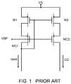
- W/L ratios of the input side transistor M 1 and the output side transistor M 2determine the overall current gain.
- Errors regarding the amplitudes of the current deliveredarise mainly due to the finite output impedance of the stimulator and any mismatch errors between the input side transistor M 1 and the output side transistor M 2 .
- One technique to compensate for the effects of the output impedance of the stimulatoris to configure the circuit of FIG. 1 to include transistors MC 1 and MC 2 in a cascode arrangement in order to increase the output impedance of the stimulator.
- the W's and/or L's of the transistorsare usually increased.
- the negative effect however of increasing the device W and Lis a marked slow down of the response time of stimulator between turn on to turn off and vice versa by virtue of increased transistor capacitances. This slow down is particularly realized when the stimulator current is programmed for low current amplitudes.
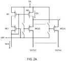
- stimulator output currentis to be individually and independently programmed through a plurality of electrodes rather than through just a single electrode.
- the cascode transistormay be split into a number of cascode transistors, that is transistors MC( 2 ) to MC(n), supplying output current to respective “loads” and that the overall output current equals the input DAC current times a current gain K.
- the number of outputs OUT( 2 ) to OUT(n) delivering output currentis controllable by switching the gates of the individual cascode transistors to voltage source VBP for turning on a particular transistor and to VS for turning off the particular transistor.
- individual output currentsas well as the overall sum of individual output currents, will vary as a function of different electrode/tissue impedances and the voltages at each of the outputs.
- one technique to reduce these variationsis to use differential amplifiers or operational amplifiers (op amps) in an attempt to regulate stimulator operation.
- one input to the op amp 20 designated as Ais the common interconnection of the drains of the cascode transistors MC( 2 ) to MC(n) while another input to the op amp 20 designated as B is a predetermined reference voltage.
- the regulated design of FIG. 2Bstrives to maintain the voltage at input A equal to the voltage at input B for a constant current ID 2 flowing through transistor M 2 independent of the number of outputs being turned on or off.
- a designmay be helpful in some instances to ensure fast turn on time under different output current levels including small output current delivery conditions especially with a multiplicity of programmable stimulating electrodes that are capable of outputting large current levels.
- the turn on times for delivering small output current levelsare usually very long. This is mainly due to the fact that only small currents are available to flow through the transistors for small output current levels to charge the parasitic capacitances of the transistors, especially the gate-to-source capacitances.
- the turn on timesare even longer, especially for high voltage stimulators that can be programmed to have large current outputs.
- very large high voltage transistorsare required for the required large output current levels due to the relatively low gain of these transistors.
- due to the relatively high threshold voltages associated with these high voltage transistorsit will take longer time to have the small current outputs charging up the gate-to-source voltages to higher than the threshold voltages in order to turn on these high voltage transistors.
- One non-limiting embodiment of the present inventionincludes pairs of transistors, preferably MOSFET transistors, each pair being connected in a current mirror configuration and coupled to a supply transistor in a cascode arrangement.
- Each pair of transistorshas an input side transistor and an output side transistor, the output side transistor of each pair being electrically coupled to a respective and corresponding tissue stimulating electrode.
- the output side transistorstherefore implement a circuit for providing multiple current stimulator capability.
- the present inventionalso includes an operational or differential amplifier having one input coupled to a reference voltage and another input coupled to the output side transistors and an output which drives the supply transistor. In steady state, the operational amplifier maintains the voltage at the output side transistor equal to the reference voltage.
- a current sourcesupplies constant current through a first resistor to establish the reference voltage and a voltage source supplies all the stimulation current through a second resistor to establish the voltage at the output side transistor.
- a current gain Kwhich represents the factor that multiplies the value of the constant current to provide the total stimulation current is equal to the ratio of the values of the first resistor and the second resistor.
- the output of the operational amplifieris very large due to the difference in amplifier input voltages and thus the supply transistor which is driven by the operational amplifier provides large initial currents to discharge the capacitances associated with the output side transistors which results in a major improvement (reduction) in stimulator turn on time almost independent of the number of stimulator outputs.
- the peripherally-implantable neurostimulation systemcan include a pulse generator including a reference current generator that generates a reference current, and a multiple output current stimulator circuit.
- the multiple output current stimulator circuitcan include a current source that can be, for example, connected to the reference current generator.
- the multiple output current stimulator circuitcan include a first resistor coupled to the current source to provide a reference voltage, and at least one output side transistor having a current output terminal for providing an output current.
- the multiple output current stimulator circuitcan include a second resistor coupled between a voltage source and the at least one output side transistor to thereby provide a common sensing voltage, and a differential amplifier.
- the differential amplifiercan include a first input coupled to the reference voltage, a second input coupled to the common sensing voltage, and an output arranged to drive the at least one output side transistor as a function of the difference between the reference voltage and the common sensing voltage.
- the peripherally-implantable neurostimulation systemcan include a lead connected to the pulse generator.
- This leadcan include a plurality of conductive electrodes and plurality of non-conductive regions.
- the pulse generatorcan include a plurality of electrical pulse programs that can, for example, affect the frequency and strength of electrical pulses generated by the pulse generator.
- the peripherally-implantable neurostimulation systemcan include a controller that can communicate with the pulse generator to create one of the plurality of electrical pulse programs and/or a controller that can communicate with the pulse generator to select one of the plurality of electrical pulse programs.
- the peripherally-implantable neurostimulation systemcan include a first switch located between the output of the differential amplifier and the output side transistor. This first switch can be closed according to one of the plurality of electrical pulse programs.
- the systemincludes a pulse generator that can generate one or several electrical pulses.
- the pulse generatorcan include a current generator that can generate a reference current, and a stimulator that includes a stimulator circuit.
- the stimulator circuitamplifies the reference current according to a ratio of resistances of a first resistor and a second resistor.
- the systemcan include one or more leads connected to the pulse generator.
- the one or more leadscan include one or more electrodes and the one or more leads can conduct the one or several electrical pulses from the pulse generator to the one or more electrodes.
- the stimulator circuitcan include a differential amplifier having a first input and a second input.
- the first resistorcan be coupled to the first input and the second resistor can be coupled to the second input.
- the peripherally-implantable neurostimulation systemincludes a plurality of outputs in electrical connection with the second resistor, and in some embodiments of the system, a stimulator output current flowing through the second resistor is equal to the sum of the current flowing through the outputs.
- one or both of the first resistor and the second resistorcan be a plurality of resistors.
- the plurality of resistors of the first resistorcan be arranged in series, and/or in some embodiments, the plurality of resistors of the second resistor can be arranged in parallel.
- the systemincludes a pulse generator that can generate one or several electrical pulses.
- the pulse generatorcan include a current generator that can generate a reference current, and a stimulator including a stimulator circuit.
- the stimulator circuitcan include a supply transistor having an output connected to one or several gates of one or several output transistors.
- the systemcan include one or more leads connected to the pulse generator, which one or more leads can include one or more electrodes. In some embodiments, the one or more leads can conduct the one or several electrical pulses from the pulse generator to the one or more electrodes.
- the drain of the supply transistorcan be connected to one or several gates of one or several output transistors.
- the peripherally-implantable neurostimulation systemcan include a differential amplifier.
- the output of the differential amplifiercan be arranged to drive the supply transistor.
- the methodcan include implanting a pulse generator in a peripheral portion of a body, which pulse generator can generate one or several electrical pulses.
- the pulse generatorcan include a stimulator circuit that can amplify the reference current according to a ratio of resistances of a first resistor and a second resistor.
- the methodcan include implanting a lead within the peripheral portion of the body, which lead can include one or more electrodes, positioning the one or more electrodes of the lead proximate to a peripheral nerve, and connecting the lead to the pulse generator.
- the method of treating neuropathic paincan further include generating an electrical pulse with the pulse generator; and conducting the electrical pulse to the peripheral nerve with the lead.
- the methodcan include implanting a pulse generator in a peripheral portion of a body, which pulse generator can generate one or several electrical pulses.
- the pulse generatorcan include a stimulator circuit that can include a supply transistor having an output connected to one or several gates of one or several output transistors.
- the methodcan include implanting a lead within the peripheral portion of the body, which lead can include one or more electrodes, positioning the one or more electrodes of the lead proximate to a peripheral nerve, and connecting the lead to the pulse generator.
- the method of treating neuropathic paincan include generating an electrical pulse with the pulse generator, and conducting the electrical pulse to the peripheral nerve with the lead.
- the systemincludes a pulse generator that can generate one or several electrical pulses.
- the pulse generatorcan include a current generator that can generate a reference current, and a stimulator that can include a stimulator circuit.
- the stimulator circuithas a turn on time of less than 5 us for an output current of less than 50 mA.
- the systemcan include one or more leads connected to the pulse generator.
- the one or more leadscan include one or more electrodes, which one or more leads can conduct the one or several electrical pulses from the pulse generator to the one or more electrodes.
- the turn on timeis less than 2 us for an output current between 200 uA and 25 mA. In some embodiments of the peripherally-implantable neurostimulation system, the turn on time is between 0.5 and 2 us for an output current between 200 uA and 25 mA. In some embodiments of the peripherally-implantable neurostimulation system, the pulse generator can generate at least one electrical pulse having a pulse width of 50 us.
- the neurostimulation systemincludes an implantable pulse generator.
- the implantable pulse generatorincludes a first resistance, a reference signal generator that can generate a reference signal, the reference signal being at least one of a reference voltage extending across, or a reference current flowing through the first resistance, and a second resistance.
- the neurostimulation systemcan include a plurality of electrode outputs, and a multi-output stimulator that can amplify the reference signal to a total output signal.
- the total output signalcan be at least one of a total output voltage or a total output current extending across or flowing through the second resistance.
- the multi-output stimulatorcan distribute the total output signal to at least some of the plurality of electrode outputs. In some embodiments, a gain value of the amplification by the multi-output stimulator is based on the first resistance and the second resistance.
- the neurostimulation systemcan include one or more leads that include a plurality of electrodes that can be coupled to the plurality of electrode outputs.
- the gain value of the amplification by the multi-output stimulatoris equal to the first resistance divided by the second resistance.
- the first resistancecan include a plurality of resistors in series, and in some embodiments, the second resistance can include a plurality of resistors in parallel.
- the implantable pulse generatoris sized for implantation in a peripheral portion of a human body, and in some embodiments, the peripheral portion of the human body can be one of an arm, a leg, a hand, and a foot.
- FIG. 1is a single output stimulator circuit using a cascode current mirror configuration of the prior art
- FIG. 2Ais a multiple output stimulator circuit using a cascode current mirror
- FIG. 2Bis a multiple output stimulator circuit using a regulated cascode current mirror
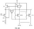
- FIG. 3is an overall block diagram of the multiple output current stimulator system of the present invention.
- FIG. 4Ais a current sensing multiple output stimulator circuit using an op amp and resistor ratios to produce a desired current gain
- FIG. 4Bis a detailed circuit diagram for a current sensing multiple output stimulator circuit of the present invention.
- FIG. 5shows timing diagrams for a multiple output current stimulator with and without the fast turn on time of the present invention.
- FIG. 6is a schematic illustration of one embodiment of a peripherally-implantable neurostimulation system.
- FIG. 3there is shown an overall block diagram of one example of a multiple output current stimulator system, and specifically, one embodiment of a pulse generator.
- the systemincludes both an anodic multiple output stimulator block 10 A and a cathodic multiple output stimulator block 10 B.
- the systemprovides for selecting either an anodic or cathodic stimulator based upon tissue stimulation requirements determined by a clinician.
- the outputs of the anodic and cathodic stimulatorsare selected by setting the corresponding “bits” in digital registers 2 .
- Digital registers 2generate digital control signals DCS, which control the selection of the anodic and cathodic stimulators.
- FIG. 3discloses two stimulators 10 A and 10 B, the discussion below with reference to FIGS.
- FIG. 4A and 4Bfocuses solely on the anodic stimulator 10 A. It is to be understood that in some embodiments a complementary circuit for the cathodic stimulator (not shown in FIG. 4A or 4B ) functions in accordance with the same principles of operation as does the anodic stimulator and therefore is not included in the following discussion merely for purposes of brevity.
- Digital registers 2also store information regarding stimulation pulse duration, amplitude and profile as well as other operational parameters. Based upon information stored in digital registers 2 and the CLOCK signal, stimulation controller 30 generates the desired stimulation pulse amplitude and triggers digital to analog converter DAC 4 to generate an output. Based upon the DAC 4 output, reference current source generator 6 provides a sink for Isink current (shown as Isink PORT in FIGS. 4A and 4B ) for the anodic stimulator and provides a source current Isource for the cathodic stimulator. Stimulation controller 30 generates turn on signal ANO to turn on the anodic stimulator 10 A to output anodic current at the selected outputs (OUT( 2 ) to OUT(n) in FIG.
- Isink currentshown as Isink PORT in FIGS. 4A and 4B
- Stimulation controller 30generates turn on signal ANO to turn on the anodic stimulator 10 A to output anodic current at the selected outputs (OUT( 2 ) to OUT(n) in FIG
- stimulation controller 30also generates turn on signal CAT to turn on cathodic stimulator 10 B to output cathodic current at the selected outputs according to the programmed cathodic pulse amplitude, duration and profile.
- FIG. 4Aa schematic illustration of one non-limiting embodiment of the current sensing multiple output current stimulator circuit 11 A is shown.
- FIG. 4Aincludes only the anodic multiple output stimulator circuit and it is to be understood that a complementary circuit for cathodic stimulation although not shown in FIG. 4A is to be considered as optionally included in the overall circuit and system.
- the inventionalso contemplates the use of a single multiple output stimulator whether it be for anodic or cathodic stimulation.
- currentdesignated as Isink flows through resistor R 1 from voltage source VS and a voltage VR 1 is generated across resistor R 1 by virtue of the current Isink flowing through R 1 .
- Reference voltage VREF 14is generated as a function of current Isink flowing through resistor R 1 and is coupled to the positive input of operational amplifier (op amp) 16 .
- op ampoperational amplifier
- the current Isinkis coupled to reference current generator 6 shown in FIG. 3 via Isink PORT, as shown in FIG. 4A .
- current sensing multiple output current stimulator circuit 11 Auses resistors R 1 and R 2 and opamp 16 to control the gate voltages of the cascode transistors MC( 2 ) to MC(n) for achieving an accurate overall stimulator output current IR 2 .
- Circuit 11 Afurther includes at least one transistor.
- the source of transistor MC( 2 )is connected to voltage source VS through resistor R 2 .
- the source of transistor MC( 2 )is also connected to the negative input of op amp 16 and provides a sensing voltage to op amp 16 .
- the drain of transistor MC( 2 ), designated as OUT( 2 ),is coupled to a respective electrode (not shown) for delivery of stimulation current to the tissue in contact with such respective electrode.
- the op amp 16is directly connected to the gate terminals of MC( 2 ) to MC(n) through a set of switches SA( 1 ) to SA(n) and SB( 1 ) to SB(n).
- these switchescan be, for example, “single pole single throw switches.”
- the switches SA( 1 ) to SA(n) connected between the op amp 16 output and the corresponding gate terminals of MC( 2 ) to MC(n)are turned on (conducting).
- Switch SA( 1 )is controlled by logic circuits 35 such that when logic circuits 35 receive signal ANO from controller 30 and digital control signals DCS from digital registers 2 , then logic circuits 35 actuate switch SA( 1 ) (causes SA( 1 ) to close) and stimulation current is delivered from output OUT( 2 ) to its respective electrode. When logic circuits 35 de-activate switch SA( 1 ) (causes SA( 1 ) to open), current delivery from output OUT( 2 ) is suspended.
- logic circuits 35cause switch SB( 1 ) to be activated.
- Stimulation therapymay be wirelessly controlled by an auxiliary device, such as a remote control or smart phone, to control the timing and duration of the activation of switches SA( 1 ) and SB( 1 ) so as to provide the desired current delivery in accordance with a predetermined therapy protocol.
- logic circuits 35control the states of switches SA( 1 ) and SB( 1 ) in a complementary fashion such that when switch SA( 1 ) is activated, switch SB( 1 ) is de-activated and vice versa.
- voltage VR 1is generated across resistor R 1 when the current Isink flows from voltage source VS through resistor R 1 .
- voltage VR 2is generated across R 2 when the overall stimulator output current IR 2 flows through resistor R 2 from voltage source VS.
- the voltage at the positive input of op amp 16is the voltage sensed at the sources of transistors MC( 1 ) to MC(n) when the corresponding switches SA( 1 ) to SA(n) are activated and may be considered a common sensing voltage.
- the voltages at the positive and negative inputs of op amp 16will be equal in steady state, and therefore, voltage VR 2 is forced to be equal to VR 1 .
- resistorsmay have better matched characteristics than MOSFETs in an integrated circuit as a function of area. For the same part to part matching accuracy, using resistors as described herein uses less area on an integrated circuit than using MOSFETs.
- An additional benefit in some instancesmay arise from the manner in which the resistors R 1 and R 2 may be constructed.
- Still another advantage in some instancesrelates to the use of the disclosed current gain dependent resistor value technique because no calibration is typically required to achieve the required current gain accuracy and hence providing additional power and die area savings.
- FIG. 4Bthere is shown another embodiment of the current sensing multiple output current stimulator circuit 11 B of the present invention.
- FIG. 4Bincludes only the anodic multiple output stimulator circuit and it is to be understood that a complementary circuit for cathodic stimulation although not shown in FIG. 4B is to be considered as optionally included in the overall circuit and system.
- the inventionalso contemplates the use of a single multiple output stimulator whether it be for anodic or cathodic stimulation.
- currentdesignated as Isink flows through resistor R 1 from voltage source VS and a voltage VR 1 is generated across resistor R 1 by virtue of the current Isink flowing through R 1 .
- Reference voltage VREF 14is generated as a function of current Isink flowing through resistor R 1 and is coupled to the negative input of operational amplifier (op amp) 16 .
- op ampoperational amplifier
- the current Isinkis coupled to reference current generator 6 shown in FIG. 3 via Isink PORT, as shown in FIG. 4B .
- Circuit 11 Bfurther includes at least one pair of transistors coupled in a current mirror connection arrangement. More specifically, the gate of input side transistor ML( 1 ) is coupled to the gate of output side transistor MC( 1 ) and the commonly connected gate 32 is also connected to the drain of transistor ML( 1 ).
- the source of transistor MC( 1 )is connected to voltage source VS through resistor R 2 and the source of transistor ML( 1 ) is connected to VS through resistor R 3 .
- the source of transistor MC( 1 )is also connected to the positive input of op amp 16 and provides a sensing voltage to op amp 16 .
- the drain of transistor MC( 1 ), designated as OUT( 1 ),is coupled to a respective electrode (not shown) for delivery of stimulation current to the tissue in contact with such respective electrode.
- the current mirror combination of transistors ML( 1 ) and MC( 1 )is switchably coupled in a cascode arrangement to supply transistor MS through switch SA( 1 ). More specifically, the drain of transistor ML( 1 ) is coupled to one side of a “single pole single throw” switch SA( 1 ) and the drain of transistor MS is coupled to the other side of switch SA( 1 ).
- the source of transistor MSis coupled to voltage port 12 , which for an anodic stimulator is ground and the gate of transistor MS is coupled to the output of op amp 16 .
- the voltage portis a voltage source such as VS.
- Switch SA( 1 )is controlled by logic circuits 35 such that when logic circuits 35 receive signal ANO from controller 30 and digital control signals DCS from digital registers 2 , then logic circuits 35 actuate switch SA( 1 ) (causes SA( 1 ) to close) and stimulation current is delivered from output OUT( 1 ) to its respective electrode. When logic circuits 35 de-activate switch SA( 1 ) (causes SA( 1 ) to open), current delivery from output OUT( 1 ) is suspended.
- logic circuits 35cause switch SB( 1 ) to be activated.
- Stimulation therapymay be wirelessly controlled by an auxiliary device, such as a remote control or smart phone, to control the timing and duration of the activation of switches SA( 1 ) and SB( 1 ) so as to provide the desired current delivery in accordance with a predetermined therapy protocol.
- logic circuits 35control the states of switches SA( 1 ) and SB( 1 ) in a complementary fashion such that when switch SA( 1 ) is activated, switch SB( 1 ) is de-activated and vice versa.
- FIG. 4Bdiscloses transistor combinations comprising transistors ML( 1 ) to ML(n) and MC( 1 ) to MC(n), where n is the number of the individual current mirror combinations to supply stimulation current to n respective electrodes.
- each current mirror combinationcomprising ML( 1 ) and MC( 1 ) to ML(n) and MC(n) is coupled to supply transistor MS through a respective switch SA( 1 ) to SA(n).
- each output side transistor MC(i)provides a common sensing voltage applied to the positive input of op amp 16 .
- the output current delivered from any one output OUT(i) of a respective current mirror combination ML(i) and MC(i) to a respective electrode i,is controlled by digital registers 2 and logic circuits 35 by activating a respective switch SA(i) in accordance with a therapy or stimulation protocol.
- the protocolmay instruct the stimulator to cause any output OUT(i) to provide stimulation current one at a time, or simultaneously in any combination or in any sequence and for any period of time.
- resistors R 1 and R 2 in combination with op amp 16control the gate voltage of supply transistor MS for achieving an accurate overall stimulator output current IR 2 flowing through resistor R 2 .
- the overall stimulator output current IR 2 flowing through resistor R 2is the sum of the currents flowing to outputs OUT( 1 ) through OUT(n) when the corresponding switches SA( 1 ) to SA(n) are activated.
- the common gate connection(shown for example as 32 for ML( 1 ) and MC( 1 )) of each current mirror coupled pair of transistors ML(i) and MC(i) is connected to voltage source VS through corresponding and respective switch SB(i).
- the state of the switches SB( 1 ) to SB(n)is determined by logic circuits 35 , such that when stimulation current is directed to a specific output OUT(i), the logic circuits 35 cause switch SA(i) to be activated and switch SB(i) to be de-activated, whereby current is delivered to OUT(i) through transistor MC(i).
- Voltage VR 1is generated across resistor R 1 when the current Isink flows from voltage source VS through resistor R 1 .
- voltage VR 2is generated across R 2 when the overall stimulator output current IR 2 flows through resistor R 2 from voltage source VS.
- the voltage at the positive input of op amp 16is the voltage sensed at the sources of transistors MC( 1 ) to MC(n) when the corresponding switches SA( 1 ) to SA(n) are activated and may be considered a common sensing voltage. Due to the feedback loop associated with op amp 16 , the voltages at the positive and negative inputs of op amp 16 will be equal in steady state, and therefore, voltage VR 2 is forced to be equal to VR 1 .
- resistorshave better matched characteristics than MOSFETs in an integrated circuit for the same area. For the same part to part matching accuracy, using resistors in some applications of the present invention require less area on an integrated circuit than using MOSFETs.
- An additional benefit arising out of some applications of the present inventionrelates to the manner in which the resistors R 1 and R 2 may be constructed.
- Still another advantage of some applications of the present inventionrelates to the use of the disclosed current gain dependent resistor value technique because no calibration is typically required to achieve the required current gain accuracy and hence providing additional power and die area savings.
- transistors ML( 1 ) and MC( 1 )are set to have a width (W) to length (L) or W/L ratio of 1:L and the ratio of R 3 to R 2 is set to L:1.
- the current ID 4is well defined and substantially independent of process and temperature variations.
- a further novel advantage of the implementation of op amp 16 in the stimulator circuit 11 B in some applicationsis that during circuit activation, that is, when stimulation controller 30 issues the ANO signal which causes Isink to flow to thereby provide VREF and with IR 2 equal to zero amps, the voltage difference between VR 1 and VR 2 is large such that the output voltage of op amp 16 is very large.
- logic circuits 35timed whether it be just prior to or concurrent with the providing of VREF, activate at least one or more preselected switches SA(i) corresponding to the outputs OUT(i) through which current is selected to be delivered.
- op amp 16drives supply transistor MS to have a large initial gate to source voltage to thereby produce a large initial drain current ID 4 .
- the gate voltages of the selected transistors MC(i) corresponding to the selected switches SA(i)are drawn down quickly for turning these transistors on quickly.
- a large initial current ID 4occurs to discharge the large gate capacitances of selected transistors MC(i) quickly, resulting in a very short stimulator turn on time.
- the large initial current ID 4is designed to discharge all of the gate capacitances of the selected transistors MC(i).
- This novel advantagemay be very important in some applications, especially for short output current pulses in some instances.
- the stimulation controller 30 in FIG. 3when the stimulation controller 30 in FIG. 3 generates the signal ANO as shown in waveform 51 with the current Isink output as shown in waveform 52 into reference current generator 6 , there will be a significant delay time TD 1 as shown in waveform 53 from the rising edge Ton of ANO to one of the stimulator output currents Iout(i) for a stimulator, such as the stimulator of FIG. 2B , that does not have a short turn on time. Nevertheless, as shown in waveform 53 , the turn off time for a typical stimulator is almost instantaneous after the falling edge Toff of ANO.
- the output current pulse produced by Iout(i)will be significantly shortened from the pulse width defined by the pulse width of ANO as illustrated in waveform 53 of FIG. 5 . If the pulse width of ANO is shorter than TD 1 , Iout(i) will completely disappear.
- TD 1will be over 100 us for a stimulator design based on FIG. 2A that utilizes high voltage transistors for realizing MC( 1 ) to MC(n).
- the width-to-length ratio between M( 1 ) and M( 2 )is 1:100 and the maximum output current of individual outputs (OUT( 2 ) to OUT(n)) is over 25 mA.
- high voltage transistors MC( 2 ) to MC(n)are very large and have very large gate to source capacitances.
- the shortest pulseis usually longer than 50 us.
- Waveform 54 in FIG. 5shows the benefit of the fast turn on characteristic of one non-limiting application of the present invention in that the time delay TD 2 between Ton and the midpoint of the rising edge of current Iout(i) is very short, compared to the much longer time delay TD 1 shown in waveform 53 of FIG. 5 .
- the delay time TD 1is often dependent on the amplitudes (or levels) of Iout(i) and/or the total output current IR 2 into all the stimulation electrodes. Furthermore, there will be variations in TD 1 between different stimulators implemented in different ICs due to process variations. Therefore, it is very difficult to correctly compensate for the delay time TD 1 by adjusting the pulse width of ANO. In some embodiments, it may be advantageous to have a pulse generator that is capable of short turn on time over a range of output currents.
- the pulse generatormay have turn on times less than 10 us, 5 us, 2 us, 1 us or any other or intermediate value and/or between, approximately 0.1 and 2 us, 0.1 and 4 us, 0.1 and 10 us, 0.1 and 20 us, 0.2 and 16 us, 0.3 and 12 us, 0.4 and 8 us, 0.5 and 6 us, 0.5 and 4 us, 0.5 and 2 us, 0.5 and 1 us, or any other or intermediate turn on time.
- these turn on timescan be achieved for output currents of less than 100 mA, 75 mA, 50 mA, 25 mA, or any other or intermediate current, and/or between 50 uA and 100 mA, 100 uA and 75 mA, 150 uA and 50 mA, 200 uA and 25 mA, 500 uA and 10 mA, or any other or intermediate current. In some embodiments, and as used above, approximately can comprise 10 percent of the defined range.
- FIG. 4Bdepicts on embodiment of a circuit 11 B with a short turn on time. In FIG.
- circuit 11 Bhas a turn on time in the range of 0.5-2 us for a total output current IR 2 ranging between 200 uA and 25 mA for the number of working outputs being between 1 and 8. Even without any compensation of the pulse width of ANO, this short turn on time is quite tolerable even for the shortest pulse width of 50 us.
- the op amp frequency responseis independent of the overall current IR 2 and the number of outputs being turned on since the output of the op amp is only connected to the gate terminal of the supply transistor MS. Furthermore, due to the large initial current ID 4 on the supply transistor as mentioned above, MC( 1 ) to MC(n) are drawn down quickly for turning these transistors on quickly without using a high current driving capability op amp. Therefore, the turn on time of the present invention of FIG. 4B will be much shorter than that of the stimulator based on the circuit topology of FIG. 4A .
- Circuit 11 A, 11 Bcan be used in a variety of stimulation devices. In one embodiment, the above mentioned advantages of circuit 11 A, 11 B enable use of circuit 11 A, 11 B in a peripherally-implantable neurostimulation system for treating neuropathic pain or for other uses.
- Neuropathic painchronic intractable pain due to nerve damage. In about 5% of people, this pain is severe. There are at least 200,000 patients that have chronic intractable pain involving a nerve. Neuropathic pain can be very difficult to treat with only half of patients achieving partial relief. Thus, determining the best treatment for individual patients remains challenging. Conventional treatments include certain antidepressants, anti-epileptic drugs and opioids. However, side effects from these drugs can be detrimental. In some of these cases, electrical stimulation, including FES, can provide effect treatment of this pain without the drug-related side effects.
- a spinal cord stimulatorwhich is one type of FES device, is a device used to deliver pulsed electrical signals to the spinal cord to control chronic pain. Because electrical stimulation is a purely electrical treatment and does not cause side effects similar to those caused by drugs, an increasing number of physicians and patients favor the use of electrical stimulation over drugs as a treatment for pain. The exact mechanisms of pain relief by spinal cord stimulation (SCS) are unknown.
- SCSspinal cord stimulation
- the scientific background of the SCS trialswas based initially on the Gate Control Theory of pain that was first described by Melzack and Wall in 1965. The theory posits that pain is transmitted by two kinds of afferent nerve fibers. One is the larger myelinated A ⁇ fiber, which carries quick, intense-pain messages.
- a third type of nerve fiberis “non-nociceptive,” meaning it does not transmit pain stimuli.
- the gate control theoryasserts that signals transmitted by the A ⁇ and C pain fibers can be thwarted by the activation/stimulation of the non-nociceptive A ⁇ fibers and thus inhibit an individual's perception of pain.
- neurostimulationprovides pain relief by blocking the pain messages before they reach the brain.
- SCSis used mostly in the treatment of failed back surgery syndrome, a complex regional pain syndrome that has refractory pain due to ischemia.
- SCS complicationshave been reported in 30% to 40% of all SCS patients. This increases the overall costs of patient pain management and decreases the efficacy of SCS.
- Common complicationsinclude: infection, hemorrhaging, injury of nerve tissue, placing device into the wrong compartment, hardware malfunction, lead migration, lead breakage, lead disconnection, lead erosion, pain at the implant site, generator overheating, and charger overheating.
- the occurrence rates of common complicationsare surprisingly high: 9.5% are accounted for lead extension connection issues, 6% are due to lead breakage, 22.6% of cases are associated with lead migration and 4.5% experienced infection.
- Peripheral neuropathymay be either inherited or acquired.
- causes of acquired peripheral neuropathyinclude physical injury (trauma) to a nerve, viruses, tumors, toxins, autoimmune responses, nutritional deficiencies, alcoholism, diabetes, and vascular and metabolic disorders.
- Acquired peripheral neuropathiesare grouped into three broad categories: those caused by systemic disease, those caused by trauma, and those caused by infections or autoimmune disorders affecting nerve tissue.
- One example of an acquired peripheral neuropathyis trigeminal neuralgia, in which damage to the trigeminal nerve (the large nerve of the head and face) causes episodic attacks of excruciating, lightning-like pain on one side of the face.
- PNSperipheral nerve stimulation
- SCSspinal cord and not for peripheral nerve stimulation
- Current SCS devicesare large and bulky.
- the SCS generatoris typically implanted in the abdominal or in the lower back above the buttocks and long leads are tunneled across multiple joints to reach the target peripheral nerves in the arms, legs or face.
- the excessive tunneling and the crossing of jointsleads to increased post-surgical pain and higher device failure rates.
- rigid leadscan lead to skin erosion and penetration, with lead failure rates nearing 100% within 3 years of implantation. Most complications result in replacement surgery and even multiple replacement surgeries in some cases.
- peripherally-implantable neurostimulation system 600One embodiment of a peripherally-implantable neurostimulation system 600 is shown in FIG. 6 .
- the peripherally-implantable neurostimulation system 600can be used in treating patients with, for example, chronic, severe, refractory neuropathic pain originating from peripheral nerves.
- the peripherally-implantable neurostimulation system 600can be used to either stimulate a target peripheral nerve or the posterior epidural space of the spine.
- the peripherally-implantable neurostimulation system 600can include one or several pulse generators.
- the pulse generatorscan comprise a variety of shapes and sizes, and can be made from a variety of materials.
- the one or several pulse generatorscan generate electrical pulses that are delivered to the nerve to control pain.
- a pulse generatorcan be an external pulse generator 602 or an implantable pulse generator 604 .
- an external pulse generator 602can be used to evaluate the suitability of a patient for treatment with the peripherally-implantable neurostimulation system 600 and/or for implantation of an implantable pulse generator 604 .
- the implantable pulse generator 604can be sized and shaped, and made of material so as to allow implantation of the implantable pulse generator 604 inside of a body. In some embodiments, the implantable pulse generator 604 can be sized and shaped so as to allow placement of the implantable pulse generator 604 at any desired location in a body, and in some embodiments, placed proximate to peripheral nerve such that leads (discussed below) are not tunneled across joints and/or such that extension cables are not needed. In some embodiments, the pulse generator, and specifically the implantable pulse generator 604 and/or the external pulse generator 602 can incorporate one of the circuits 11 A, 11 B, as shown in either or both of the embodiments of FIGS. 4A and 4B .
- the electrical pulses generated by the pulse generatorcan be delivered to one or several nerves 610 and/or to tissue proximate to one or several nerves 610 via one or several leads.
- the leadscan include conductive portions, referred to as electrodes, and non-conductive portions.
- the leadscan have a variety of shapes, be a variety of sizes, and be made from a variety of materials, which size, shape, and materials can be dictated by the application or other factors.
- the leadscan include an anodic lead 606 and/or a cathodic lead 608 .
- the anodic lead 606 and the cathodic lead 608can be identical leads, but can receive pulses of different polarity from the pulse generator.
- the leadscan connect directly to the pulse generator, and in some embodiments, the leads can be connected to the pulse generator via a connector 612 and a connector cable 614 .
- the connector 612can comprise any device that is able to electrically connect the leads to the connector cable 614 .
- the connector cablecan be any device capable of transmitting distinct electrical pulses to the anodic lead 606 and the cathodic lead 608 .
- the peripherally-implantable neurostimulation system 600can include a charger 616 that can be configured to recharge the implantable pulse generator 604 when the implantable pulse generator 604 is implanted within a body.
- the charger 616can comprise a variety of shapes, sizes, and features, and can be made from a variety of materials.
- the charger 616can recharge the implantable pulse generator 604 via an inductive coupling.
- details of the electrical pulsescan be controlled via a controller. In some embodiments, these details can include, for example, the frequency, strength, pattern, duration, or other aspects of the timing and magnitude of the electrical pulses.
- This control of the electrical pulsescan include the creation of one or several electrical pulse programs, plans, or patterns, and in some embodiments, this can include the selection of one or several pre-existing electrical pulse programs, plans, or patterns.
- the peripherally-implantable neurostimulation system 600includes a controller that is a clinician programmer 618 .
- the clinician programmer 618can be used to create one or several pulse programs, plans, or patterns and/or to select one or several of the created pulse programs, plans, or patterns.
- the clinician programmer 618can be used to program the operation of the pulse generators including, for example, one or both of the external pulse generator 602 and the implantable pulse generator 604 .
- the clinician programmer 618can comprise a computing device that can wiredly and/or wirelessly communicate with the pulse generators.
- the clinician programmer 618can be further configured to receive information from the pulse generators indicative of the operation and/or effectiveness of the pulse generators and the leads.
- the controller of the peripherally-implantable neurostimulation system 600can include a patient remote 620 .
- the patient remote 620can comprise a computing device that can communicate with the pulse generators via a wired or wireless connection.
- the patient remote 620can be used to program the pulse generator, and in some embodiments, the patient remote 620 can include one or several pulse generation programs, plans, or patterns created by the clinician programmer 618 .
- the patient remote 620can be used to select one or several of the pre-existing pulse generation programs, plans, or patterns and to select, for example, the duration of the selected one of the one or several pulse generation programs, plans, or patterns.
- peripherally-implantable neurostimulation system 600can be used to control and provide the generation of electrical pulses to mitigate patient pain.
Landscapes
- Health & Medical Sciences (AREA)
- Engineering & Computer Science (AREA)
- Life Sciences & Earth Sciences (AREA)
- Public Health (AREA)
- Neurology (AREA)
- Biomedical Technology (AREA)
- Nuclear Medicine, Radiotherapy & Molecular Imaging (AREA)
- Radiology & Medical Imaging (AREA)
- Veterinary Medicine (AREA)
- Animal Behavior & Ethology (AREA)
- General Health & Medical Sciences (AREA)
- Neurosurgery (AREA)
- Pain & Pain Management (AREA)
- Electrotherapy Devices (AREA)
- Physics & Mathematics (AREA)
- Electromagnetism (AREA)
- General Physics & Mathematics (AREA)
- Radar, Positioning & Navigation (AREA)
- Automation & Control Theory (AREA)
Abstract
Description
Claims (17)
Priority Applications (2)
| Application Number | Priority Date | Filing Date | Title |
|---|---|---|---|
| US15/980,642US10603495B2 (en) | 2013-03-15 | 2018-05-15 | Current sensing multiple output current stimulators |
| US16/792,102US11338144B2 (en) | 2013-03-15 | 2020-02-14 | Current sensing multiple output current stimulators |
Applications Claiming Priority (4)
| Application Number | Priority Date | Filing Date | Title |
|---|---|---|---|
| US201361788871P | 2013-03-15 | 2013-03-15 | |
| US14/217,321US9446241B2 (en) | 2013-03-15 | 2014-03-17 | Current sensing multiple output current stimulators |
| US15/263,046US9981130B2 (en) | 2013-03-15 | 2016-09-12 | Current sensing multiple output current stimulators |
| US15/980,642US10603495B2 (en) | 2013-03-15 | 2018-05-15 | Current sensing multiple output current stimulators |
Related Parent Applications (1)
| Application Number | Title | Priority Date | Filing Date |
|---|---|---|---|
| US15/263,046ContinuationUS9981130B2 (en) | 2013-03-15 | 2016-09-12 | Current sensing multiple output current stimulators |
Related Child Applications (1)
| Application Number | Title | Priority Date | Filing Date |
|---|---|---|---|
| US16/792,102DivisionUS11338144B2 (en) | 2013-03-15 | 2020-02-14 | Current sensing multiple output current stimulators |
Publications (2)
| Publication Number | Publication Date |
|---|---|
| US20190015664A1 US20190015664A1 (en) | 2019-01-17 |
| US10603495B2true US10603495B2 (en) | 2020-03-31 |
Family
ID=50629012
Family Applications (4)
| Application Number | Title | Priority Date | Filing Date |
|---|---|---|---|
| US14/217,321Active2034-10-22US9446241B2 (en) | 2013-03-15 | 2014-03-17 | Current sensing multiple output current stimulators |
| US15/263,046Active2034-06-05US9981130B2 (en) | 2013-03-15 | 2016-09-12 | Current sensing multiple output current stimulators |
| US15/980,642ActiveUS10603495B2 (en) | 2013-03-15 | 2018-05-15 | Current sensing multiple output current stimulators |
| US16/792,102Active2034-08-18US11338144B2 (en) | 2013-03-15 | 2020-02-14 | Current sensing multiple output current stimulators |
Family Applications Before (2)
| Application Number | Title | Priority Date | Filing Date |
|---|---|---|---|
| US14/217,321Active2034-10-22US9446241B2 (en) | 2013-03-15 | 2014-03-17 | Current sensing multiple output current stimulators |
| US15/263,046Active2034-06-05US9981130B2 (en) | 2013-03-15 | 2016-09-12 | Current sensing multiple output current stimulators |
Family Applications After (1)
| Application Number | Title | Priority Date | Filing Date |
|---|---|---|---|
| US16/792,102Active2034-08-18US11338144B2 (en) | 2013-03-15 | 2020-02-14 | Current sensing multiple output current stimulators |
Country Status (7)
| Country | Link |
|---|---|
| US (4) | US9446241B2 (en) |
| EP (1) | EP2974016B1 (en) |
| JP (1) | JP6298145B2 (en) |
| CN (1) | CN105164920B (en) |
| AU (1) | AU2014232252B2 (en) |
| CA (1) | CA2903843C (en) |
| WO (1) | WO2014146016A2 (en) |
Cited By (1)
| Publication number | Priority date | Publication date | Assignee | Title |
|---|---|---|---|---|
| US11338144B2 (en) | 2013-03-15 | 2022-05-24 | Alfred E. Mann Foundation For Scientific Research | Current sensing multiple output current stimulators |
Families Citing this family (41)
| Publication number | Priority date | Publication date | Assignee | Title |
|---|---|---|---|---|
| EP2773423B1 (en) | 2011-11-04 | 2024-01-10 | Nevro Corporation | Medical device communication and charding assemblies for use with implantable signal generators |
| WO2013111137A2 (en) | 2012-01-26 | 2013-08-01 | Rainbow Medical Ltd. | Wireless neurqstimulatqrs |
| US10369370B2 (en) | 2012-04-26 | 2019-08-06 | Medtronic, Inc. | Trial stimulation systems |
| WO2014087337A1 (en) | 2012-12-06 | 2014-06-12 | Bluewind Medical Ltd. | Delivery of implantable neurostimulators |
| WO2014179685A1 (en) | 2013-05-03 | 2014-11-06 | Nevro Corporation | Molded headers for implantable signal generators, and associated systems and methods |
| US9780596B2 (en) | 2013-07-29 | 2017-10-03 | Alfred E. Mann Foundation For Scientific Research | Microprocessor controlled class E driver |
| WO2015179177A1 (en) | 2014-05-20 | 2015-11-26 | Nevro Corporation | Implanted pulse generators with reduced power consumption via signal strength/duration characteristics, and associated systems and methods |
| EP3191176B1 (en) | 2014-10-22 | 2024-04-10 | Nevro Corp. | Systems and methods for extending the life of an implanted pulse generator battery |
| US9517344B1 (en) | 2015-03-13 | 2016-12-13 | Nevro Corporation | Systems and methods for selecting low-power, effective signal delivery parameters for an implanted pulse generator |
| AU2016291554B2 (en) | 2015-07-10 | 2021-01-07 | Axonics Modulation Technologies, Inc. | Implantable nerve stimulator having internal electronics without ASIC and methods of use |
| US10105540B2 (en) | 2015-11-09 | 2018-10-23 | Bluewind Medical Ltd. | Optimization of application of current |
| AU2016382867B2 (en)* | 2015-12-31 | 2021-12-23 | Nevro Corp. | Controller for nerve stimulation circuit and associated systems and methods |
| JP6876363B2 (en) | 2016-01-29 | 2021-05-26 | アクソニクス モジュレーション テクノロジーズ インコーポレイテッド | Methods and systems for frequency adjustment that optimize the charging of implantable neurostimulators |
| US11040192B2 (en)* | 2016-09-10 | 2021-06-22 | Boston Scientific Neuromodulation Corporation | Current generation architecture for an implantable medical device |
| US10549091B2 (en) | 2016-09-10 | 2020-02-04 | Boston Scientific Neuromodulation Corporation | Use models for a current generation architecture for an implantable medical device |
| US10124178B2 (en) | 2016-11-23 | 2018-11-13 | Bluewind Medical Ltd. | Implant and delivery tool therefor |
| US11311728B2 (en)* | 2017-01-20 | 2022-04-26 | The Regents Of The University Of California | Electrode agnostic, supply variant stimulation engine for implantable neural stimulation |
| US10471259B2 (en) | 2017-02-28 | 2019-11-12 | Medtronic, Inc. | Devices and methods for sensing physiological signals during stimulation therapy |
| US20180353764A1 (en) | 2017-06-13 | 2018-12-13 | Bluewind Medical Ltd. | Antenna configuration |
| AU2018222994B2 (en) | 2017-09-15 | 2019-11-07 | Boston Scientific Neuromodulation Corporation | Current generation architecture for an implantable stimulator device to promote current steering between electrodes |
| EP4101500B1 (en) | 2017-09-15 | 2024-10-30 | Boston Scientific Neuromodulation Corporation | Current generation architecture for an implantable stimulator device including distributor circuitry for sending an amplitude-scaled current to digital-to-analog converters at the electrodes |
| CN109908472B (en)* | 2017-12-13 | 2023-11-10 | 伊藤超短波株式会社 | Electric therapeutic equipment |
| WO2019152553A1 (en) | 2018-01-30 | 2019-08-08 | Jon Parker | Efficient use of an implantable pulse generator battery, and associated systems and methods |
| US11602627B2 (en) | 2018-03-20 | 2023-03-14 | Second Heart Assist, Inc. | Circulatory assist pump |
| JP7284593B2 (en)* | 2018-03-22 | 2023-05-31 | 株式会社東芝 | current drive circuit |
| AU2019398172B2 (en)* | 2018-12-12 | 2024-02-15 | Battelle Memorial Institute | Electrical stimulation devices and systems for safely operating such devices |
| US10933238B2 (en) | 2019-01-31 | 2021-03-02 | Nevro Corp. | Power control circuit for sterilized devices, and associated systems and methods |
| US11642537B2 (en) | 2019-03-11 | 2023-05-09 | Axonics, Inc. | Charging device with off-center coil |
| WO2020206332A1 (en)* | 2019-04-05 | 2020-10-08 | William Marsh Rice University | Magnetoelectric data and power to miniature biodevices with tunable amplitude and waveform |
| WO2020242900A1 (en) | 2019-05-24 | 2020-12-03 | Axonics Modulation Technologies, Inc. | Trainer device for a neurostimulator programmer and associated methods of use with a neurostimulation system |
| CN110320949A (en)* | 2019-06-18 | 2019-10-11 | 中国科学院自动化研究所 | Voltage controlled current source circuit and channel-cranium electro-stimulating device including it |
| US11119524B1 (en)* | 2020-03-11 | 2021-09-14 | Cirrus Logic, Inc. | Glitch mitigation in selectable output current mirrors with degeneration resistors |
| TWI731756B (en)* | 2020-07-22 | 2021-06-21 | 國立臺灣科技大學 | Charge compensation device, charge compensation method, and electrical stimulation generating system including charge compensation device |
| CN112648693B (en)* | 2020-12-18 | 2023-08-04 | 青岛海信日立空调系统有限公司 | Air conditioner and multi-channel PFC circuit control method |
| WO2022217184A1 (en) | 2021-04-06 | 2022-10-13 | Boston Scientific Neuromodulation Corporation | Current generation architecture for an implantable stimulator device |
| FR3125970B1 (en)* | 2021-08-03 | 2023-08-18 | Neurinnov | INTRINSICALLY BALANCED NEURAL STIMULATION DEVICE |
| US11400299B1 (en) | 2021-09-14 | 2022-08-02 | Rainbow Medical Ltd. | Flexible antenna for stimulator |
| WO2024163265A1 (en)* | 2023-01-30 | 2024-08-08 | President And Fellows Of Harvard College | Dram-style bidirectional current injector and multi-electrode apparatus with dram-style bidirectional current injectors |
| DE102023104126A1 (en)* | 2023-02-20 | 2024-08-22 | Neuroloop GmbH | Electrical circuit arrangement for generating current-controlled electrical signals |
| PL447125A1 (en)* | 2023-12-16 | 2024-07-15 | Netrix Spółka Akcyjna | Hybrid system for stabilizing and regulating the excitation current value in the electrical process tomography system |
| WO2025207978A1 (en) | 2024-03-29 | 2025-10-02 | The Alfred E. Mann Foundation For Scientific Research | Implantable medical systems with medical leads with multiple neural interfaces |
Citations (228)
| Publication number | Priority date | Publication date | Assignee | Title |
|---|---|---|---|---|
| US3646940A (en) | 1969-07-15 | 1972-03-07 | Univ Minnesota | Implantable electronic stimulator electrode and method |
| US3942535A (en) | 1973-09-27 | 1976-03-09 | G. D. Searle & Co. | Rechargeable tissue stimulating system |
| US4019518A (en) | 1975-08-11 | 1977-04-26 | Medtronic, Inc. | Electrical stimulation system |
| US4044774A (en) | 1976-02-23 | 1977-08-30 | Medtronic, Inc. | Percutaneously inserted spinal cord stimulation lead |
| US4082097A (en) | 1976-05-20 | 1978-04-04 | Pacesetter Systems Inc. | Multimode recharging system for living tissue stimulators |
| US4340062A (en) | 1978-11-06 | 1982-07-20 | Medtronic, Inc. | Body stimulator having selectable stimulation energy levels |
| US4468723A (en) | 1981-04-24 | 1984-08-28 | Hewlett-Packard Company | Magnetically regulated power supply |
| US4558702A (en) | 1983-01-21 | 1985-12-17 | Cordis Corporation | Cardiac pacer having input/output circuit programmable for use with unipolar and bipolar pacer leads |
| US4673867A (en) | 1986-06-30 | 1987-06-16 | Motorola, Inc. | Current mirror circuit and method for providing zero temperature coefficient trimmable current ratios |
| US4744371A (en) | 1987-04-27 | 1988-05-17 | Cordis Leads, Inc. | Multi-conductor lead assembly for temporary use |
| US5143089A (en) | 1989-05-03 | 1992-09-01 | Eckhard Alt | Assembly and method of communicating electrical signals between electrical therapeutic systems and body tissue |
| US5193539A (en) | 1991-12-18 | 1993-03-16 | Alfred E. Mann Foundation For Scientific Research | Implantable microstimulator |
| US5690693A (en) | 1995-06-07 | 1997-11-25 | Sulzer Intermedics Inc. | Transcutaneous energy transmission circuit for implantable medical device |
| US5702428A (en) | 1992-05-23 | 1997-12-30 | Axelgaard Manufacturing Company, Ltd. | Electrical stimulation for treatment of incontinence and other neuro-muscular disorders |
| US5702431A (en) | 1995-06-07 | 1997-12-30 | Sulzer Intermedics Inc. | Enhanced transcutaneous recharging system for battery powered implantable medical device |
| US5735887A (en) | 1996-12-10 | 1998-04-07 | Exonix Corporation | Closed-loop, RF-coupled implanted medical device |
| US5741316A (en) | 1996-12-02 | 1998-04-21 | Light Sciences Limited Partnership | Electromagnetic coil configurations for power transmission through tissue |
| US5876423A (en) | 1996-06-04 | 1999-03-02 | Biotronik Mess- Und Therapiegeraete Gmbh & Co. Ingenieurbuero Berlin | Implantable stimulator with terminal voltage control of a depletable voltage source |
| US5877472A (en) | 1996-02-22 | 1999-03-02 | Pacesetter, Inc. | System for laser-welding components of an implantable device |
| US6027456A (en) | 1998-07-10 | 2000-02-22 | Advanced Neuromodulation Systems, Inc. | Apparatus and method for positioning spinal cord stimulation leads |
| US6035237A (en) | 1995-05-23 | 2000-03-07 | Alfred E. Mann Foundation | Implantable stimulator that prevents DC current flow without the use of discrete output coupling capacitors |
| US6055456A (en) | 1999-04-29 | 2000-04-25 | Medtronic, Inc. | Single and multi-polar implantable lead for sacral nerve electrical stimulation |
| US6057513A (en) | 1997-01-29 | 2000-05-02 | Ngk Insulators, Ltd. | Joint structure of metal member and ceramic member and method of producing the same |
| US6067474A (en) | 1997-08-01 | 2000-05-23 | Advanced Bionics Corporation | Implantable device with improved battery recharging and powering configuration |
| US6076017A (en) | 1997-04-30 | 2000-06-13 | Medtronic, Inc. | Method of centerless ground finishing of feedthrough pins for an implantable medical device |
| WO2000056677A1 (en) | 1999-03-24 | 2000-09-28 | Alfred E. Mann Foundation | Method and apparatus of a strong metal-ceramic braze bond |
| WO2000066221A1 (en) | 1999-05-03 | 2000-11-09 | Abiomed, Inc. | Electromagnetic field source with detection of position of secondary coil in relation to multiple primary coils |
| US6164284A (en) | 1997-02-26 | 2000-12-26 | Schulman; Joseph H. | System of implantable devices for monitoring and/or affecting body parameters |
| US6172556B1 (en) | 1999-03-04 | 2001-01-09 | Intersil Corporation, Inc. | Feedback-controlled low voltage current sink/source |
| US6178353B1 (en) | 1998-07-27 | 2001-01-23 | Advanced Bionics Corporation | Laminated magnet keeper for implant device |
| US6185452B1 (en) | 1997-02-26 | 2001-02-06 | Joseph H. Schulman | Battery-powered patient implantable device |
| US6191365B1 (en) | 1997-05-02 | 2001-02-20 | General Science And Technology Corp | Medical devices incorporating at least one element made from a plurality of twisted and drawn wires |
| US6208894B1 (en) | 1997-02-26 | 2001-03-27 | Alfred E. Mann Foundation For Scientific Research And Advanced Bionics | System of implantable devices for monitoring and/or affecting body parameters |
| US6212431B1 (en) | 1998-09-08 | 2001-04-03 | Advanced Bionics Corporation | Power transfer circuit for implanted devices |
| US6221513B1 (en) | 1998-05-12 | 2001-04-24 | Pacific Coast Technologies, Inc. | Methods for hermetically sealing ceramic to metallic surfaces and assemblies incorporating such seals |
| US6246911B1 (en) | 1999-02-08 | 2001-06-12 | Peter Seligman | Cochlear implants with offset coils for transmission of radio frequency links |
| US6249703B1 (en) | 1994-07-08 | 2001-06-19 | Medtronic, Inc. | Handheld patient programmer for implantable human tissue stimulator |
| US6265789B1 (en) | 1997-11-20 | 2001-07-24 | Seiko Epson Corporation | Electronic apparatus |
| US6306100B1 (en) | 1997-12-16 | 2001-10-23 | Richard L. Prass | Intraoperative neurophysiological monitoring system |
| US6313779B1 (en) | 2000-06-19 | 2001-11-06 | Ka Y. Leung | Comparator-amplifier configuration in an ADC |
| WO2002003408A2 (en) | 2000-06-30 | 2002-01-10 | Medtronic, Inc. | Implantable medical device having flat electrolytic capacitor with cathode/case electrical connections |
| WO2002009808A1 (en) | 2000-07-26 | 2002-02-07 | Advanced Bionics Corporation | Rechargeable spinal cord stimulator system |
| US6354991B1 (en) | 1998-10-06 | 2002-03-12 | Bio Control Medical Ltd | Incontinence treatment device |
| US6393325B1 (en) | 1999-01-07 | 2002-05-21 | Advanced Bionics Corporation | Directional programming for implantable electrode arrays |
| US6427086B1 (en) | 1997-10-27 | 2002-07-30 | Neuropace, Inc. | Means and method for the intracranial placement of a neurostimulator |
| US6438423B1 (en) | 2000-01-20 | 2002-08-20 | Electrocore Technique, Llc | Method of treating complex regional pain syndromes by electrical stimulation of the sympathetic nerve chain |
| US20020116042A1 (en) | 2001-02-20 | 2002-08-22 | Boling C. Lance | Furcated sensing and stimulation lead |
| US6442434B1 (en) | 1999-10-19 | 2002-08-27 | Abiomed, Inc. | Methods and apparatus for providing a sufficiently stable power to a load in an energy transfer system |
| US6466817B1 (en) | 1999-11-24 | 2002-10-15 | Nuvasive, Inc. | Nerve proximity and status detection system and method |
| US6505075B1 (en) | 1999-05-29 | 2003-01-07 | Richard L. Weiner | Peripheral nerve stimulation method |
| US6516227B1 (en) | 1999-07-27 | 2003-02-04 | Advanced Bionics Corporation | Rechargeable spinal cord stimulator system |
| US20030028072A1 (en) | 2000-08-31 | 2003-02-06 | Neuropace, Inc. | Low frequency magnetic neurostimulator for the treatment of neurological disorders |
| JP2003047179A (en) | 2001-07-26 | 2003-02-14 | Matsushita Electric Works Ltd | Contactless electric power transmission device |
| US6521350B2 (en) | 2001-06-18 | 2003-02-18 | Alfred E. Mann Foundation For Scientific Research | Application and manufacturing method for a ceramic to metal seal |
| US20030078633A1 (en) | 2001-09-28 | 2003-04-24 | Firlik Andrew D. | Methods and implantable apparatus for electrical therapy |
| US6584355B2 (en) | 2001-04-10 | 2003-06-24 | Cardiac Pacemakers, Inc. | System and method for measuring battery current |
| US6600954B2 (en) | 2001-01-25 | 2003-07-29 | Biocontrol Medical Bcm Ltd. | Method and apparatus for selective control of nerve fibers |
| US6609031B1 (en) | 1996-06-07 | 2003-08-19 | Advanced Neuromodulation Systems, Inc. | Multiprogrammable tissue stimulator and method |
| US6662051B1 (en) | 2000-03-31 | 2003-12-09 | Stephen A. Eraker | Programmable pain reduction device |
| US6721603B2 (en) | 2002-01-25 | 2004-04-13 | Cyberonics, Inc. | Nerve stimulation as a treatment for pain |
| US6735474B1 (en) | 1998-07-06 | 2004-05-11 | Advanced Bionics Corporation | Implantable stimulator system and method for treatment of incontinence and pain |
| US6745077B1 (en) | 2000-10-11 | 2004-06-01 | Advanced Bionics Corporation | Electronic impedance transformer for inductively-coupled load stabilization |
| US20040106963A1 (en) | 2001-11-07 | 2004-06-03 | Quallion Llc | Implantable medical power module |
| US6809701B2 (en) | 2001-08-03 | 2004-10-26 | Cardiac Pacemakers, Inc. | Circumferential antenna for an implantable medical device |
| WO2004103465A1 (en) | 2003-05-16 | 2004-12-02 | Medtronic, Inc. | Headset recharger for cranially implantable medical devices |
| US6836684B1 (en) | 1998-10-30 | 2004-12-28 | Neurocon Aps | Method to control an overactive bladder |
| US6847849B2 (en) | 2000-11-15 | 2005-01-25 | Medtronic, Inc. | Minimally invasive apparatus for implanting a sacral stimulation lead |
| US6864755B2 (en) | 2000-10-06 | 2005-03-08 | Alfred E. Mann Institute For Biomedical Engineering At The University Of Southern California | Switched reactance modulated E-class oscillator design |
| US6892098B2 (en) | 2001-04-26 | 2005-05-10 | Biocontrol Medical Ltd. | Nerve stimulation for treating spasticity, tremor, muscle weakness, and other motor disorders |
| US20050104577A1 (en) | 1997-02-26 | 2005-05-19 | Eusebiu Matei | System for determining relative distance(s) and/or angle(s) between at least two points |
| US6896651B2 (en) | 1998-10-06 | 2005-05-24 | Biocontrol Medical Ltd. | Mechanical and electrical sensing for incontinence treatment |
| US6901287B2 (en) | 2001-02-09 | 2005-05-31 | Medtronic, Inc. | Implantable therapy delivery element adjustable anchor |
| US6941171B2 (en) | 1998-07-06 | 2005-09-06 | Advanced Bionics Corporation | Implantable stimulator methods for treatment of incontinence and pain |
| US20050267546A1 (en)* | 2004-05-28 | 2005-12-01 | Jordi Parramon | Low power loss current digital-to-analog converter used in an implantable pulse generator |
| US6971393B1 (en) | 2000-11-15 | 2005-12-06 | George Mamo | Minimally invasive method for implanting a sacral stimulation lead |
| US6986453B2 (en) | 2003-11-13 | 2006-01-17 | Alfred E. Mann Foundation For Scientific Research | Manufacturing method for a ceramic to metal seal |
| US6989200B2 (en) | 2003-10-30 | 2006-01-24 | Alfred E. Mann Foundation For Scientific Research | Ceramic to noble metal braze and method of manufacture |
| US6990376B2 (en) | 2002-12-06 | 2006-01-24 | The Regents Of The University Of California | Methods and systems for selective control of bladder function |
| US20060016452A1 (en) | 2004-07-20 | 2006-01-26 | Medtronic, Inc. | Locating an implanted object based on external antenna loading |
| US6999819B2 (en) | 2001-08-31 | 2006-02-14 | Medtronic, Inc. | Implantable medical electrical stimulation lead fixation method and apparatus |
| US20060050539A1 (en) | 2004-09-09 | 2006-03-09 | Ta-Yung Yang | Switching control circuit with variable switching frequency for primary-side-controlled power converters |
| US7054689B1 (en) | 2000-08-18 | 2006-05-30 | Advanced Bionics Corporation | Fully implantable neurostimulator for autonomic nerve fiber stimulation as a therapy for urinary and bowel dysfunction |
| US7051419B2 (en) | 1999-09-16 | 2006-05-30 | Micronet Medical, Inc. | Neurostimulating lead |
| US7069081B2 (en) | 2001-02-08 | 2006-06-27 | Wilson Greatbatch Ltd. | One piece header assembly for an implantable medical device |
| US20060142822A1 (en) | 2002-12-12 | 2006-06-29 | Metin Tulgar | Externally activated neuro-implant which directly transmits therapeutic signals |
| EP1680182A1 (en) | 2003-10-02 | 2006-07-19 | Medtronic, Inc. | External power source for an implantable medical device having an adjustable carrier frequency and system and method related therefore |
| US7114502B2 (en) | 1997-02-26 | 2006-10-03 | Alfred E. Mann Foundation For Scientific Research | Battery-powered patient implantable device |
| US7127298B1 (en) | 2002-10-18 | 2006-10-24 | Advanced Bionics Corporation | Switched-matrix output for multi-channel implantable stimulator |
| US7142925B1 (en) | 1998-09-16 | 2006-11-28 | Axon Engineering, Inc. | Combined stimulation of ventral and dorsal sacral roots for control of bladder function |
| US7146219B2 (en) | 2002-10-31 | 2006-12-05 | Medtronic, Inc. | Applying filter information to identify combinations of electrodes |
| US7151914B2 (en) | 2001-08-21 | 2006-12-19 | Medtronic, Inc. | Transmitter system for wireless communication with implanted devices |
| US7167749B2 (en) | 2002-11-05 | 2007-01-23 | Wilson Greatbatch Technologies, Inc. | One piece header assembly for an implantable medical device |
| US7177698B2 (en) | 2002-06-28 | 2007-02-13 | Advanced Bionics Corporation | Telemetry system for use with microstimulator |
| US7177690B2 (en) | 1999-07-27 | 2007-02-13 | Advanced Bionics Corporation | Implantable system having rechargeable battery indicator |
| US7181286B2 (en) | 2002-10-31 | 2007-02-20 | Medtronic, Inc. | Distributed system for neurostimulation therapy programming |
| US7187978B2 (en) | 2001-11-01 | 2007-03-06 | Medtronic, Inc. | Method and apparatus for programming an implantable medical device |
| US20070073357A1 (en) | 2005-06-09 | 2007-03-29 | Medtronic, Inc. | Peripheral nerve field stimulation and spinal cord stimulation |
| US7212110B1 (en) | 2004-04-19 | 2007-05-01 | Advanced Neuromodulation Systems, Inc. | Implantable device and system and method for wireless communication |
| CN1956750A (en) | 2004-05-24 | 2007-05-02 | 于利奇研究中心有限公司 | Devices, electronic components and uses of devices and electronic components in medicine for treating patients by brain stimulation |
| US7225032B2 (en) | 2003-10-02 | 2007-05-29 | Medtronic Inc. | External power source, charger and system for an implantable medical device having thermal characteristics and method therefore |
| US7231254B2 (en) | 1998-08-05 | 2007-06-12 | Bioneuronics Corporation | Closed-loop feedback-driven neuromodulation |
| US7234853B2 (en) | 2000-08-07 | 2007-06-26 | Luminex S.P.A. | Textile product with illuminated fibers manufacturing process |
| US7245972B2 (en) | 2004-04-29 | 2007-07-17 | Alfred E. Mann Foundation For Scientific Research | Electrical treatment to treat shoulder subluxation |
| US7286880B2 (en) | 2003-10-02 | 2007-10-23 | Medtronic, Inc. | System and method for transcutaneous energy transfer achieving high efficiency |
| US20070265675A1 (en) | 2006-05-09 | 2007-11-15 | Ams Research Corporation | Testing Efficacy of Therapeutic Mechanical or Electrical Nerve or Muscle Stimulation |
| US7305268B2 (en) | 2000-07-13 | 2007-12-04 | Northstar Neurscience, Inc. | Systems and methods for automatically optimizing stimulus parameters and electrode configurations for neuro-stimulators |
| US7317948B1 (en) | 2002-02-12 | 2008-01-08 | Boston Scientific Scimed, Inc. | Neural stimulation system providing auto adjustment of stimulus output as a function of sensed impedance |
| US7324852B2 (en) | 2004-02-25 | 2008-01-29 | Giancarlo Barolat | System and method for neurological stimulation of peripheral nerves to treat low back pain |
| US7328068B2 (en) | 2003-03-31 | 2008-02-05 | Medtronic, Inc. | Method, system and device for treating disorders of the pelvic floor by means of electrical stimulation of the pudendal and associated nerves, and the optional delivery of drugs in association therewith |
| WO2008021524A2 (en) | 2006-08-18 | 2008-02-21 | Second Sight Medical Products, Inc. | Package for an implantable neural stimulation device |
| EP1904153A1 (en) | 2005-04-29 | 2008-04-02 | Medtronic, Inc. | Alignment indication for transcutaneous energy transfer |
| US7359751B1 (en) | 2004-05-05 | 2008-04-15 | Advanced Neuromodulation Systems, Inc. | Clinician programmer for use with trial stimulator |
| US7369894B2 (en) | 2002-09-06 | 2008-05-06 | Medtronic, Inc. | Method, system and device for treating disorders of the pelvic floor by electrical stimulation of the sacral and/or pudendal nerves |
| US20080132961A1 (en) | 2006-11-30 | 2008-06-05 | Advanced Bionics Corporation | Implant tool for use with a microstimulator |
| US7386348B2 (en) | 1999-09-29 | 2008-06-10 | Medtronic, Inc. | Patient interactive neurostimulation system and method |
| US7396265B2 (en) | 2002-09-30 | 2008-07-08 | Cochlear Limited | Feedthrough for electrical connectors |
| US20080172109A1 (en) | 2007-01-11 | 2008-07-17 | Advanced Bionics Corporation | Multiple Telemetry and/or Charging Coil Configurations for an Implantable Medical Device System |
| US7415308B2 (en) | 2005-02-23 | 2008-08-19 | Medtronic, Inc. | Implantable medical device providing adaptive neurostimulation therapy for incontinence |
| US7444181B2 (en) | 2005-12-14 | 2008-10-28 | Boston Scientific Neuromodulation Corporation | Techniques for sensing and adjusting a compliance voltage in an implantable stimulator device |
| US7450991B2 (en) | 2004-05-28 | 2008-11-11 | Advanced Neuromodulation Systems, Inc. | Systems and methods used to reserve a constant battery capacity |
| US20080278974A1 (en) | 2007-05-08 | 2008-11-13 | Tsung-Hsiu Wu | Quasi-resonant fly-back converter without auxiliary winding |
| US7460911B2 (en) | 1997-02-26 | 2008-12-02 | Alfred E. Mann Foundation For Scientific Research | System and method suitable for treatment of a patient with a neurological deficit by sequentially stimulating neural pathways using a system of discrete implantable medical devices |
| US7463928B2 (en) | 2003-04-25 | 2008-12-09 | Medtronic, Inc. | Identifying combinations of electrodes for neurostimulation therapy |
| US7470236B1 (en) | 1999-11-24 | 2008-12-30 | Nuvasive, Inc. | Electromyography system |
| US7483752B2 (en) | 2001-03-02 | 2009-01-27 | Cardiac Pacemakers, Inc. | Antenna for an implantable medical device |
| US20090088816A1 (en) | 1999-03-05 | 2009-04-02 | Tami Harel | Gastrointestinal Methods And Apparatus For Use In Treating Disorders And Controlling Blood Sugar |
| US7515967B2 (en) | 2003-10-02 | 2009-04-07 | Medtronic, Inc. | Ambulatory energy transfer system for an implantable medical device and method therefore |
| WO2009051539A1 (en) | 2007-10-16 | 2009-04-23 | Milux Holding Sa | A method and system for controlling supply of energy to an implantable medical device |
| US20090105785A1 (en) | 2007-09-26 | 2009-04-23 | Medtronic, Inc. | Therapy program selection |
| US20090112291A1 (en) | 2007-10-26 | 2009-04-30 | Medtronic, Inc. | Closed loop long range recharging |
| US7532936B2 (en) | 2004-04-20 | 2009-05-12 | Advanced Neuromodulation Systems, Inc. | Programmable switching device for implantable device |
| US7551960B2 (en) | 2005-09-08 | 2009-06-23 | Medtronic, Inc. | External presentation of electrical stimulation parameters |
| US7555346B1 (en) | 1999-01-07 | 2009-06-30 | Boston Scientific Neuromodulation Corporation | Implantable pulse generator having current steering means |
| US7565203B2 (en) | 1999-03-24 | 2009-07-21 | Second Sight Medical Products, Inc. | Package for an implantable medical device |
| WO2009091267A2 (en) | 2008-01-18 | 2009-07-23 | Telemetry Research Limited | Selectable resonant frequency transcutaneous energy transfer system |
| US7578819B2 (en) | 2005-05-16 | 2009-08-25 | Baxano, Inc. | Spinal access and neural localization |
| US20090259273A1 (en) | 2008-04-10 | 2009-10-15 | Medtronic, Inc. | Using telemetry coupling as a surrogate for recharger coupling |
| US7617002B2 (en) | 2003-09-15 | 2009-11-10 | Medtronic, Inc. | Selection of neurostimulator parameter configurations using decision trees |
| US7636602B2 (en) | 2003-04-02 | 2009-12-22 | Neurostream Technologies General Partnership | Fully implantable nerve signal sensing and stimulation device and method for treating foot drop and other neurological disorders |
| US7640059B2 (en) | 2005-09-08 | 2009-12-29 | Medtronic, Inc. | External presentation of electrical stimulation parameters |
| US20100076534A1 (en) | 2006-10-25 | 2010-03-25 | William Alan Mock | Malleable needle having a plurality of electrodes for facilitating implantation of stimulation lead and method of implanting an electrical stimulation lead |
| US20100076254A1 (en) | 2006-06-05 | 2010-03-25 | Ams Research Corporation | Electrical muscle stimulation to treat fecal incontinence and/or pelvic prolapse |
| WO2010042056A1 (en) | 2008-10-10 | 2010-04-15 | Milux Holding S.A. | Charger for implant with means for indicating alignment between charger and implant |
| WO2010042057A1 (en) | 2008-10-10 | 2010-04-15 | Milux Holding S.A. | Charger for implant |
| US7706889B2 (en) | 2006-04-28 | 2010-04-27 | Medtronic, Inc. | Tree-based electrical stimulator programming |
| US7720547B2 (en) | 2006-01-04 | 2010-05-18 | Kenergy, Inc. | Extracorporeal power supply with a wireless feedback system for an implanted medical device |
| US7734355B2 (en) | 2001-08-31 | 2010-06-08 | Bio Control Medical (B.C.M.) Ltd. | Treatment of disorders by unidirectional nerve stimulation |
| US7738965B2 (en) | 2006-04-28 | 2010-06-15 | Medtronic, Inc. | Holster for charging pectorally implanted medical devices |
| US7738963B2 (en) | 2004-03-04 | 2010-06-15 | Advanced Neuromodulation Systems, Inc. | System and method for programming an implantable pulse generator |
| US7747330B2 (en) | 2006-03-09 | 2010-06-29 | Medtronic, Inc. | Global parameter adjustment for multiple stimulation programs |
| US7771838B1 (en) | 2004-10-12 | 2010-08-10 | Boston Scientific Neuromodulation Corporation | Hermetically bonding ceramic and titanium with a Ti-Pd braze interface |
| US7813803B2 (en) | 2005-06-09 | 2010-10-12 | Medtronic, Inc. | Regional therapies for treatment of pain |
| US7813809B2 (en) | 2004-06-10 | 2010-10-12 | Medtronic, Inc. | Implantable pulse generator for providing functional and/or therapeutic stimulation of muscles and/or nerves and/or central nervous system tissue |
| US7932696B2 (en) | 2007-05-14 | 2011-04-26 | Boston Scientific Neuromodulation Corporation | Charger alignment indicator with adjustable threshold |
| US7935051B2 (en) | 2002-06-26 | 2011-05-03 | Nuvasive, Inc. | Surgical access system and related methods |
| WO2011059565A1 (en) | 2009-11-11 | 2011-05-19 | Boston Scientific Neuromodulation Corporation | Structure for an implantable medical device having telemetry and charging coils within a case |
| US7952349B2 (en) | 2002-12-09 | 2011-05-31 | Ferro Solutions, Inc. | Apparatus and method utilizing magnetic field |
| US7957818B2 (en) | 2008-06-26 | 2011-06-07 | Greatbatch Ltd. | Stimulation lead design and method of manufacture |
| US20110152959A1 (en) | 2009-12-18 | 2011-06-23 | Sherwood Gregory J | Implantable energy storage device including a connection post to connect multiple electrodes |
| US7979119B2 (en) | 2005-04-26 | 2011-07-12 | Boston Scientific Neuromodulation Corporation | Display graphics for use in stimulation therapies |
| US7979126B2 (en) | 2006-10-18 | 2011-07-12 | Boston Scientific Neuromodulation Corporation | Orientation-independent implantable pulse generator |
| DE102010006837A1 (en) | 2010-02-03 | 2011-08-04 | W.C. Heraeus GmbH, 63450 | Electrical bushing for implantable device, has electrical isolating base body and electrical conducting bushing body, which are embedded in bushing aperture penetrating base body |
| US8000782B2 (en) | 2001-09-25 | 2011-08-16 | Nuvasive, Inc. | System and methods for performing surgical procedures and assessments |
| US8005550B2 (en) | 2007-09-13 | 2011-08-23 | Medtronic, Inc. | Medical electrical lead |
| US8019423B2 (en) | 2006-02-17 | 2011-09-13 | Marc Possover | Laparoscopic implantation of neurostimulators |
| US8050769B2 (en) | 2001-07-11 | 2011-11-01 | Nuvasive, Inc. | System and methods for determining nerve proximity, direction, and pathology during surgery |
| US8055337B2 (en) | 2008-07-24 | 2011-11-08 | Boston Scientific Neuromodulation Corporation | System and method for maintaining a distribution of currents in an electrode array using independent voltage sources |
| US20110276103A1 (en) | 2010-05-07 | 2011-11-10 | Maile Keith R | Output circuit for both cardiac contractile electrostimulation and non-contractile neural modulation |
| US20110282416A1 (en) | 2010-05-11 | 2011-11-17 | Hamann Jason J | Systems for patient control of implantable medical device therapy |
| US20110278948A1 (en) | 2008-11-21 | 2011-11-17 | Milux Holdings SA | System for supplying energy |
| US20110301667A1 (en) | 2003-10-02 | 2011-12-08 | Medtronic, Inc. | Inductively rechargeable external energy source, charger, system and method for a transcutaneous inductive charger for an implantable medical device |
| US20120016447A1 (en) | 2010-07-16 | 2012-01-19 | Boston Scientific Neuromodulation Corporation | System and method for estimating lead configuration from neighboring relationship between electrodes |
| US8103360B2 (en) | 2008-05-09 | 2012-01-24 | Foster Arthur J | Medical lead coil conductor with spacer element |
| US8116862B2 (en) | 2006-06-08 | 2012-02-14 | Greatbatch Ltd. | Tank filters placed in series with the lead wires or circuits of active medical devices to enhance MRI compatibility |
| US8129942B2 (en) | 2005-07-30 | 2012-03-06 | Ls Cable & System Ltd. | Contactless charging method for charging battery |
| US20120071950A1 (en) | 2010-09-20 | 2012-03-22 | Neuropace, Inc. | Current Management System for a Stimulation Output Stage of an Implantable Neurostimulation System |
| US8145324B1 (en) | 2001-04-13 | 2012-03-27 | Greatbatch Ltd. | Implantable lead bandstop filter employing an inductive coil with parasitic capacitance to enhance MRI compatibility of active medical devices |
| US8150530B2 (en) | 2005-04-28 | 2012-04-03 | Medtronic, Inc. | Activity sensing for stimulator control |
| US8175717B2 (en) | 2005-09-06 | 2012-05-08 | Boston Scientific Neuromodulation Corporation | Ultracapacitor powered implantable pulse generator with dedicated power supply |
| US8180452B2 (en) | 2000-04-20 | 2012-05-15 | Cochlear Limited | Transcutaneous power optimization circuit for a medical implant |
| US20120119698A1 (en) | 2008-09-27 | 2012-05-17 | Aristeidis Karalis | Wireless energy transfer for vehicles |
| US8214042B2 (en) | 2009-05-26 | 2012-07-03 | Boston Scientific Neuromodulation Corporation | Techniques for controlling charging of batteries in an external charger and an implantable medical device |
| US8219196B2 (en) | 2008-10-31 | 2012-07-10 | Medtronic, Inc. | Determination of stimulation output capabilities throughout power source voltage range |
| US8219202B2 (en) | 2006-04-28 | 2012-07-10 | Medtronic, Inc. | Electrical stimulation of ilioinguinal nerve to alleviate chronic pelvic pain |
| US8255057B2 (en) | 2009-01-29 | 2012-08-28 | Nevro Corporation | Systems and methods for producing asynchronous neural responses to treat pain and/or other patient conditions |
| US20120259381A1 (en) | 2011-04-07 | 2012-10-11 | Greatbatch, Ltd. | Contact assembly for implantable pulse generator and method of use |
| US20120262108A1 (en) | 2011-04-18 | 2012-10-18 | Medtronic, Inc. | Recharge tuning techniques for an implantable device |
| US20120276854A1 (en) | 2011-04-29 | 2012-11-01 | Cyberonics, Inc. | Slot Antenna For An Implantable Device |
| US20120274270A1 (en) | 2011-04-28 | 2012-11-01 | Dinsmoor David A | Implantable medical devices and systems having inductive telemetry and recharge on a single coil |
| US20120276856A1 (en) | 2011-04-29 | 2012-11-01 | Cyberonics, Inc. | Implantable medical device antenna |
| US8314594B2 (en) | 2008-04-30 | 2012-11-20 | Medtronic, Inc. | Capacity fade adjusted charge level or recharge interval of a rechargeable power source of an implantable medical device, system and method |
| US8332040B1 (en) | 2008-03-10 | 2012-12-11 | Advanced Neuromodulation Systems, Inc. | External charging device for charging an implantable medical device and methods of regulating duty of cycle of an external charging device |
| US20130004925A1 (en) | 2011-06-28 | 2013-01-03 | Greatbatch, Ltd. | Key fob controller for an implantable neurostimulator |
| US20130006331A1 (en) | 2011-07-01 | 2013-01-03 | Greatbatch Ltd. | Active Current Control Using the Enclosure of an Implanted Pulse Generator |
| US20130006330A1 (en) | 2011-06-28 | 2013-01-03 | Greatbatch, Ltd. | Dual patient controllers |
| US20130023958A1 (en) | 2011-07-19 | 2013-01-24 | Greatbatch Ltd. | Devices and Methods for Visually Indicating the Alignment of a Transcutaneous Energy Transfer Device Over an Implanted Medical Device |
| US8362742B2 (en) | 2007-10-26 | 2013-01-29 | Medtronic, Inc. | Method and apparatus for dynamic adjustment of recharge parameters |
| US8369943B2 (en) | 2006-06-06 | 2013-02-05 | Cardiac Pacemakers, Inc. | Method and apparatus for neural stimulation via the lymphatic system |
| US8386048B2 (en) | 2002-06-28 | 2013-02-26 | Boston Scientific Neuromodulation Corporation | Systems and methods for communicating with or providing power to an implantable stimulator |
| US8417346B2 (en) | 2006-04-28 | 2013-04-09 | Medtronic, Inc. | Electrical stimulation of iliohypogastric nerve to alleviate chronic pelvic pain |
| US8423146B2 (en) | 2006-01-31 | 2013-04-16 | Medtronic, Inc. | Electrical stimulation to alleviate chronic pelvic pain |
| US20130096651A1 (en) | 2011-10-13 | 2013-04-18 | Boston Scientific Neuromodulation Corporation | Charger Alignment in an Implantable Medical Device System Employing Reflected Impedance Modulation |
| US8447408B2 (en) | 2002-10-31 | 2013-05-21 | Medtronic, Inc. | Neurostimulation therapy manipulation |
| US8447402B1 (en) | 2006-03-31 | 2013-05-21 | Alfred E. Mann Foundation For Scientific Research | Zirconia to platinum assembly using a titanium connector |
| US8457756B2 (en) | 2009-11-11 | 2013-06-04 | Boston Scientific Neuromodulation Corporation | Using the case of an implantable medical device to broaden communication bandwidth |
| US20130148768A1 (en) | 2011-12-07 | 2013-06-13 | Junius Adonis Kim | Predictable coding delay over communications networks |
| US20130150925A1 (en) | 2003-06-11 | 2013-06-13 | Boston Scientific Neuromodulation Corporation | Remote control for implantable medical device |
| US8480437B2 (en) | 2008-04-11 | 2013-07-09 | Bal Seal Engineering, Inc. | Connector cartridge stack for electrical transmission |
| US8494625B2 (en) | 2002-02-04 | 2013-07-23 | Cerephex Corporation | Methods and apparatus for electrical stimulation of tissues using signals that minimize the effects of tissue impedance |
| US20130197608A1 (en) | 2012-01-27 | 2013-08-01 | Greatbatch, Ltd. | Heat dispersion for implantable medical devices |
| US20130207863A1 (en) | 2011-04-29 | 2013-08-15 | Cyberonics, Inc. | Antenna shield for an implantable medical device |
| US8515545B2 (en) | 2011-04-29 | 2013-08-20 | Greatbatch Ltd. | Current steering neurostimulator device with unidirectional current sources |
| US8538530B1 (en) | 2008-11-19 | 2013-09-17 | Advanced Bionics | Hermetically sealed feedthrough case |
| US8543223B2 (en) | 2011-03-11 | 2013-09-24 | Greatbach Ltd. | Implantable lead with braided conductors |
| US8549015B2 (en) | 2007-05-01 | 2013-10-01 | Giancarlo Barolat | Method and system for distinguishing nociceptive pain from neuropathic pain |
| US8555894B2 (en) | 1997-02-26 | 2013-10-15 | Alfred E. Mann Foundation For Scientific Research | System for monitoring temperature |
| US8571677B2 (en) | 2009-10-21 | 2013-10-29 | Medtronic, Inc. | Programming techniques for stimulation with utilization of case electrode |
| US20130303942A1 (en) | 2012-05-08 | 2013-11-14 | Case Western Reserve University | Implantable pressure sensor |
| US20130331909A1 (en) | 2005-02-23 | 2013-12-12 | Medtronic, Inc. | Implantable neurostimulator supporting trial and chronic modes |
| US8612002B2 (en) | 2009-12-23 | 2013-12-17 | Setpoint Medical Corporation | Neural stimulation devices and systems for treatment of chronic inflammation |
| US8620436B2 (en) | 2005-07-08 | 2013-12-31 | Boston Scientific Neuromodulation Corporation | Current generation architecture for an implantable stimulator device having coarse and fine current control |
| US8761897B2 (en) | 2012-08-31 | 2014-06-24 | Greatbatch Ltd. | Method and system of graphical representation of lead connector block and implantable pulse generators on a clinician programmer |
| US8768452B2 (en) | 2005-02-23 | 2014-07-01 | Medtronic, Inc. | Implantable neurostimulator supporting trial and chronic modes |
| WO2014146016A2 (en) | 2013-03-15 | 2014-09-18 | Alfred E. Mann Foundation For Scientific Research | Current sensing multiple output current stimulators with fast turn on time |
| US8989861B2 (en) | 2010-06-07 | 2015-03-24 | Medtronic, Inc. | Stimulation therapy for bladder dysfunction |
| US20150123608A1 (en) | 2013-07-29 | 2015-05-07 | Alfred E. Mann Foundation For Scientific Research | Microprocessor controlled class e driver |
| US9089712B2 (en) | 2011-04-29 | 2015-07-28 | Cyberonics, Inc. | Implantable medical device without antenna feedthrough |
| US20150214604A1 (en) | 2014-01-24 | 2015-07-30 | Medtronic, Inc. | Implantable medical devices having cofire ceramic modules and methods of fabricating the same |
Family Cites Families (240)
| Publication number | Priority date | Publication date | Assignee | Title |
|---|---|---|---|---|
| US3057356A (en) | 1960-07-22 | 1962-10-09 | Wilson Greatbatch Inc | Medical cardiac pacemaker |
| US3348548A (en) | 1965-04-26 | 1967-10-24 | William M Chardack | Implantable electrode with stiffening stylet |
| US3888260A (en) | 1972-06-28 | 1975-06-10 | Univ Johns Hopkins | Rechargeable demand inhibited cardiac pacer and tissue stimulator |
| US3825015A (en) | 1972-12-14 | 1974-07-23 | American Optical Corp | Single catheter for atrial and ventricular stimulation |
| US3824129A (en) | 1973-03-14 | 1974-07-16 | Mallory & Co Inc P R | Heart pacer rechargeable cell and protective control system |
| US3902501A (en) | 1973-06-21 | 1975-09-02 | Medtronic Inc | Endocardial electrode |
| US3970912A (en) | 1973-08-28 | 1976-07-20 | Hoffman Philip A | Battery charging circuit |
| US3939843A (en) | 1974-03-04 | 1976-02-24 | Medtronic, Inc. | Transvenous electrode |
| US3995623A (en) | 1974-12-23 | 1976-12-07 | American Hospital Supply Corporation | Multipurpose flow-directed catheter |
| US4141365A (en) | 1977-02-24 | 1979-02-27 | The Johns Hopkins University | Epidural lead electrode and insertion needle |
| US4166469A (en) | 1977-12-13 | 1979-09-04 | Littleford Philip O | Apparatus and method for inserting an electrode |
| US4285347A (en) | 1979-07-25 | 1981-08-25 | Cordis Corporation | Stabilized directional neural electrode lead |
| US4269198A (en) | 1979-12-26 | 1981-05-26 | Medtronic, Inc. | Body implantable lead |
| DE3015260A1 (en) | 1980-04-21 | 1981-10-22 | Siemens AG, 1000 Berlin und 8000 München | ENDOCARD ELECTRODE ARRANGEMENT |
| US4379462A (en) | 1980-10-29 | 1983-04-12 | Neuromed, Inc. | Multi-electrode catheter assembly for spinal cord stimulation |
| US4721118A (en) | 1981-04-20 | 1988-01-26 | Cordis Leads, Inc. | Pervenous electrical pacing lead with foldable fins |
| US4437475A (en) | 1981-08-28 | 1984-03-20 | Medtronic, Inc. | Transvenous cardiovascular integrated lead anchoring sleeve, protector, and permanent lead introducer stop gap |
| DE3146182C2 (en) | 1981-11-21 | 1984-03-29 | Peter Dr. 7889 Grenzach-Wyhlen Osypka | Electrode arrangement for a cardiac pacemaker that can be inserted transvenously into the heart |
| US4512351A (en) | 1982-11-19 | 1985-04-23 | Cordis Corporation | Percutaneous lead introducing system and method |
| US4961422A (en) | 1983-01-21 | 1990-10-09 | Marchosky J Alexander | Method and apparatus for volumetric interstitial conductive hyperthermia |
| DE3490016T1 (en) | 1983-01-21 | 1985-02-07 | Ramm Associates, Creve Coeur, Mo. | Implantable hyperthermia device and system |
| US4800898A (en) | 1983-10-07 | 1989-01-31 | Cordis Corporation | Neural stimulator electrode element and lead |
| US4654880A (en) | 1983-12-09 | 1987-03-31 | Minnesota Mining And Manufacturing Company | Signal transmission system |
| US4550731A (en) | 1984-03-07 | 1985-11-05 | Cordis Corporation | Acquisition circuit for cardiac pacer |
| US4662382A (en) | 1985-01-16 | 1987-05-05 | Intermedics, Inc. | Pacemaker lead with enhanced sensitivity |
| US4722353A (en) | 1985-09-16 | 1988-02-02 | Intermedics, Inc. | Stabilizer for implantable electrode |
| US4848352A (en) | 1987-02-13 | 1989-07-18 | Telectronics, N.V. | Method for cardiac pacing and sensing using combination of electrodes |
| US4957118A (en) | 1988-01-15 | 1990-09-18 | Jay Erlebacher | Electrode lead |
| US4860446A (en) | 1988-02-16 | 1989-08-29 | Medtronic, Inc. | Medical electrical lead and method of manufacture |
| US5052407A (en) | 1988-04-14 | 1991-10-01 | Mieczyslaw Mirowski | Cardiac defibrillation/cardioversion spiral patch electrode |
| US4989617A (en) | 1989-07-14 | 1991-02-05 | Case Western Reserve University | Intramuscular electrode for neuromuscular stimulation system |
| US5012176A (en) | 1990-04-03 | 1991-04-30 | Baxter International, Inc. | Apparatus and method for calorimetrically determining battery charge state |
| CA2038160C (en) | 1991-03-13 | 1996-10-22 | Jiri K. Nor | Charging circuits for rechargeable batteries and cells |
| US5255691A (en) | 1991-11-13 | 1993-10-26 | Medtronic, Inc. | Percutaneous epidural lead introducing system and method |
| US5257634A (en) | 1992-07-16 | 1993-11-02 | Angeion Corporation | Low impedence defibrillation catheter electrode |
| US5676651A (en) | 1992-08-06 | 1997-10-14 | Electric Boat Corporation | Surgically implantable pump arrangement and method for pumping body fluids |
| US5342408A (en) | 1993-01-07 | 1994-08-30 | Incontrol, Inc. | Telemetry system for an implantable cardiac device |
| JP3384027B2 (en) | 1993-05-14 | 2003-03-10 | ソニー株式会社 | Charging method and charger |
| US5864220A (en) | 1993-09-16 | 1999-01-26 | Chartec Laboratories A/S | Method and apparatus for controlling the charging of a rechargeable battery to ensure that full charge is achieved without damaging the battery |
| US5439485A (en) | 1993-09-24 | 1995-08-08 | Ventritex, Inc. | Flexible defibrillation electrode of improved construction |
| US5484445A (en) | 1993-10-12 | 1996-01-16 | Medtronic, Inc. | Sacral lead anchoring system |
| SE9304031D0 (en) | 1993-12-03 | 1993-12-03 | Siemens Elema Ab | electrode System |
| JPH07222370A (en) | 1994-01-28 | 1995-08-18 | Sanyo Electric Co Ltd | Charger with temperature sensor |
| US5571148A (en) | 1994-08-10 | 1996-11-05 | Loeb; Gerald E. | Implantable multichannel stimulator |
| US5712795A (en) | 1995-10-02 | 1998-01-27 | Alaris Medical Systems, Inc. | Power management system |
| US6898454B2 (en) | 1996-04-25 | 2005-05-24 | The Johns Hopkins University | Systems and methods for evaluating the urethra and the periurethral tissues |
| US5733313A (en) | 1996-08-01 | 1998-03-31 | Exonix Corporation | RF coupled, implantable medical device with rechargeable back-up power source |
| US5713939A (en) | 1996-09-16 | 1998-02-03 | Sulzer Intermedics Inc. | Data communication system for control of transcutaneous energy transmission to an implantable medical device |
| SE9604143D0 (en) | 1996-11-13 | 1996-11-13 | Pacesetter Ab | Implantable electrode cable |
| US5957965A (en) | 1997-03-03 | 1999-09-28 | Medtronic, Inc. | Sacral medical electrical lead |
| CA2230930A1 (en) | 1997-04-25 | 1998-10-25 | Dale Gathergood | Exterior rear view mirror integral warning light |
| US5871532A (en) | 1997-05-22 | 1999-02-16 | Sulzer Intermedics Inc. | Epicardial lead for minimally invasive implantation |
| IT1292016B1 (en) | 1997-05-28 | 1999-01-25 | Valerio Cigaina | IMPLANT DEVICE PARTICULARLY FOR ELECTROSTIMULATION AND / OR ELECTRO-REGISTRATION OF ENDOABDOMINAL VISCERS |
| US5991665A (en) | 1997-09-18 | 1999-11-23 | Sulzer Intermedics Inc. | Self-cooling transcutaneous energy transfer system for battery powered implantable device |
| US6138681A (en) | 1997-10-13 | 2000-10-31 | Light Sciences Limited Partnership | Alignment of external medical device relative to implanted medical device |
| US6169387B1 (en) | 1997-12-22 | 2001-01-02 | Lifecor, Inc. | Battery management apparatus for portable electronic devices |
| DE19800416C2 (en) | 1998-01-08 | 2002-09-19 | Storz Karl Gmbh & Co Kg | Device for the treatment of body tissue, in particular soft tissue close to the surface, by means of ultrasound |
| US6081097A (en) | 1998-01-19 | 2000-06-27 | Matsushita Electric Industrial Co., Ltd. | Method for charging lithium secondary battery |
| US6305381B1 (en) | 1998-02-02 | 2001-10-23 | Medtronic Inc. | System for locating implantable medical device |
| EP1056510B1 (en) | 1998-02-23 | 2005-05-11 | Medtronic, Inc. | Rf coupled, implantable medical device with rechargeable back-up power source |
| US5902331A (en) | 1998-03-10 | 1999-05-11 | Medtronic, Inc. | Arrangement for implanting an endocardial cardiac lead |
| JP3826407B2 (en) | 1998-03-24 | 2006-09-27 | セイコーエプソン株式会社 | Electronic device, electronic device control method, secondary battery capacity estimation method, and secondary battery charge control method |
| US6243608B1 (en) | 1998-06-12 | 2001-06-05 | Intermedics Inc. | Implantable device with optical telemetry |
| US6104960A (en) | 1998-07-13 | 2000-08-15 | Medtronic, Inc. | System and method for providing medical electrical stimulation to a portion of the nervous system |
| US6083247A (en) | 1998-08-10 | 2000-07-04 | Medtronic, Inc. | Perpendicular atrial fixation/stimulation loop |
| US6104957A (en) | 1998-08-21 | 2000-08-15 | Alo; Kenneth M. | Epidural nerve root stimulation with lead placement method |
| DE19838137A1 (en) | 1998-08-21 | 2000-03-02 | Implex Hear Tech Ag | Charger arrangement for rechargeable Ni Cd, Ni-metal hydride, or Lithium batteries in implant, has current source which provides high initial current |
| US5948006A (en) | 1998-10-14 | 1999-09-07 | Advanced Bionics Corporation | Transcutaneous transmission patch |
| US6275737B1 (en) | 1998-10-14 | 2001-08-14 | Advanced Bionics Corporation | Transcutaneous transmission pouch |
| US7076307B2 (en) | 2002-05-09 | 2006-07-11 | Boveja Birinder R | Method and system for modulating the vagus nerve (10th cranial nerve) with electrical pulses using implanted and external components, to provide therapy neurological and neuropsychiatric disorders |
| US20030212440A1 (en) | 2002-05-09 | 2003-11-13 | Boveja Birinder R. | Method and system for modulating the vagus nerve (10th cranial nerve) using modulated electrical pulses with an inductively coupled stimulation system |
| US5949632A (en) | 1998-12-01 | 1999-09-07 | Exonix Corporation | Power supply having means for extending the operating time of an implantable medical device |
| US6321118B1 (en) | 1999-01-28 | 2001-11-20 | Advanced Bionics Corporation | Method and apparatus for power link detection with implantable medical devices |
| US7131996B2 (en) | 1999-03-18 | 2006-11-07 | Helmut Wasserman | Artificial urinary diversion device |
| US6181105B1 (en) | 1999-04-26 | 2001-01-30 | Exonix Corporation | Self contained transportable power source maintenance and charge |
| US6166518A (en) | 1999-04-26 | 2000-12-26 | Exonix Corporation | Implantable power management system |
| US7295878B1 (en) | 1999-07-30 | 2007-11-13 | Advanced Bionics Corporation | Implantable devices using rechargeable zero-volt technology lithium-ion batteries |
| US6553263B1 (en) | 1999-07-30 | 2003-04-22 | Advanced Bionics Corporation | Implantable pulse generators using rechargeable zero-volt technology lithium-ion batteries |
| US6381496B1 (en) | 1999-10-01 | 2002-04-30 | Advanced Bionics Corporation | Parameter context switching for an implanted device |
| US6473652B1 (en) | 2000-03-22 | 2002-10-29 | Nac Technologies Inc. | Method and apparatus for locating implanted receiver and feedback regulation between subcutaneous and external coils |
| US6453198B1 (en) | 2000-04-28 | 2002-09-17 | Medtronic, Inc. | Power management for an implantable medical device |
| US7167756B1 (en) | 2000-04-28 | 2007-01-23 | Medtronic, Inc. | Battery recharge management for an implantable medical device |
| US6327504B1 (en) | 2000-05-10 | 2001-12-04 | Thoratec Corporation | Transcutaneous energy transfer with circuitry arranged to avoid overheating |
| US6505077B1 (en) | 2000-06-19 | 2003-01-07 | Medtronic, Inc. | Implantable medical device with external recharging coil electrical connection |
| US6510347B2 (en) | 2000-08-17 | 2003-01-21 | William N. Borkan | Spinal cord stimulation leads |
| DE10041728A1 (en) | 2000-08-25 | 2002-03-21 | Implex Hear Tech Ag | Implantable medicinal device with hermetically sealed housing has storage device accommodated directly within hermetically sealed housing without housing of its own |
| DE10041727C2 (en) | 2000-08-25 | 2003-04-10 | Cochlear Ltd | Implantable hermetically sealed housing for an implantable medical device |
| US6542846B1 (en) | 2000-11-09 | 2003-04-01 | Koninklijke Philips Electronics N.V. | Thermal management system for a portable ultrasound imaging device |
| US6609945B2 (en) | 2001-02-08 | 2003-08-26 | Plexus, Inc. | Radio-controlled toy blimp with infrared beam weapons for staging a gun battle |
| WO2002078592A2 (en) | 2001-03-30 | 2002-10-10 | Case Western Reserve University | Systems and methods for selectively stimulating components in, on, or near the pudendal nerve or its branches to achieve selective physiologic responses |
| US20070088416A1 (en) | 2001-04-13 | 2007-04-19 | Surgi-Vision, Inc. | Mri compatible medical leads |
| KR100606307B1 (en) | 2001-05-23 | 2006-07-28 | 안태영 | Contactless power train for human implant |
| JP3994690B2 (en) | 2001-07-03 | 2007-10-24 | 住友電装株式会社 | connector |
| JP3731881B2 (en) | 2002-05-23 | 2006-01-05 | 有限会社ティーエム | Non-invasive charging system for artificial organs, power storage device used in this system, and power supply device |
| US7860570B2 (en) | 2002-06-20 | 2010-12-28 | Boston Scientific Neuromodulation Corporation | Implantable microstimulators and methods for unidirectional propagation of action potentials |
| AU2002951217A0 (en) | 2002-09-04 | 2002-09-19 | Cochlear Limited | Method and apparatus for measurement of transmitter/receiver separation |
| US20040055610A1 (en) | 2002-09-25 | 2004-03-25 | Peter Forsell | Detection of implanted wireless energy receiving device |
| US6685638B1 (en) | 2002-12-23 | 2004-02-03 | Codman & Shurtleff, Inc. | Acoustic monitoring system |
| US9446229B2 (en) | 2003-04-08 | 2016-09-20 | Omar Omar-Pasha | Catheter |
| US20050187590A1 (en) | 2003-05-11 | 2005-08-25 | Boveja Birinder R. | Method and system for providing therapy for autism by providing electrical pulses to the vagus nerve(s) |
| US7444184B2 (en) | 2003-05-11 | 2008-10-28 | Neuro And Cardial Technologies, Llc | Method and system for providing therapy for bulimia/eating disorders by providing electrical pulses to vagus nerve(s) |
| US20040267137A1 (en) | 2003-06-27 | 2004-12-30 | Michael Peszynski | Apparatus and method for IC-based ultrasound transducer temperature sensing |
| US7286881B2 (en) | 2003-10-02 | 2007-10-23 | Medtronic, Inc. | External power source having an adjustable magnetic core and method of use |
| US8265770B2 (en) | 2003-10-02 | 2012-09-11 | Medtronic, Inc. | Driver circuitry switchable between energy transfer and telemetry for an implantable medical device |
| US8467875B2 (en) | 2004-02-12 | 2013-06-18 | Medtronic, Inc. | Stimulation of dorsal genital nerves to treat urologic dysfunctions |
| US20080132969A1 (en) | 2004-02-12 | 2008-06-05 | Ndi Medical, Inc. | Systems and methods for bilateral stimulation of left and right branches of the dorsal genital nerves to treat urologic dysfunctions |
| ATE520440T1 (en) | 2004-02-12 | 2011-09-15 | Ndi Medical Llc | WEARABLE ARRANGEMENTS AND SYSTEMS FOR FUNCTIONAL OR THERAPEUTIC NEUROMUSCULAR STIMULATION |
| US8086318B2 (en) | 2004-02-12 | 2011-12-27 | Ndi Medical, Llc | Portable assemblies, systems, and methods for providing functional or therapeutic neurostimulation |
| US7120499B2 (en) | 2004-02-12 | 2006-10-10 | Ndi Medical, Llc | Portable percutaneous assemblies, systems and methods for providing highly selective functional or therapeutic neuromuscular stimulation |
| US20080161874A1 (en) | 2004-02-12 | 2008-07-03 | Ndi Medical, Inc. | Systems and methods for a trial stage and/or long-term treatment of disorders of the body using neurostimulation |
| US7844343B2 (en) | 2004-03-30 | 2010-11-30 | Medtronic, Inc. | MRI-safe implantable medical device |
| US7225028B2 (en) | 2004-05-28 | 2007-05-29 | Advanced Bionics Corporation | Dual cochlear/vestibular stimulator with control signals derived from motion and speech signals |
| US9308382B2 (en) | 2004-06-10 | 2016-04-12 | Medtronic Urinary Solutions, Inc. | Implantable pulse generator systems and methods for providing functional and/or therapeutic stimulation of muscles and/or nerves and/or central nervous system tissue |
| US7761167B2 (en) | 2004-06-10 | 2010-07-20 | Medtronic Urinary Solutions, Inc. | Systems and methods for clinician control of stimulation systems |
| US9205255B2 (en) | 2004-06-10 | 2015-12-08 | Medtronic Urinary Solutions, Inc. | Implantable pulse generator systems and methods for providing functional and/or therapeutic stimulation of muscles and/or nerves and/or central nervous system tissue |
| US20060200205A1 (en) | 2005-03-01 | 2006-09-07 | Haller Matthew I | Systems and methods for treating a patient with multiple stimulation therapies |
| WO2006124068A1 (en) | 2005-05-13 | 2006-11-23 | Ndi Medical, Llc | Systems for electrical stimulation of nerves in adipose tissue regions |
| US7650192B2 (en) | 2005-12-02 | 2010-01-19 | Medtronic, Inc. | Passive charge of implantable medical device utilizing external power source and method |
| US8892214B2 (en) | 2006-04-28 | 2014-11-18 | Medtronic, Inc. | Multi-electrode peripheral nerve evaluation lead and related system and method of use |
| US9480846B2 (en) | 2006-05-17 | 2016-11-01 | Medtronic Urinary Solutions, Inc. | Systems and methods for patient control of stimulation systems |
| US9713706B2 (en) | 2006-10-31 | 2017-07-25 | Medtronic, Inc. | Implantable medical elongated member including intermediate fixation |
| US9643004B2 (en) | 2006-10-31 | 2017-05-09 | Medtronic, Inc. | Implantable medical elongated member with adhesive elements |
| US20080103572A1 (en) | 2006-10-31 | 2008-05-01 | Medtronic, Inc. | Implantable medical lead with threaded fixation |
| US9827415B2 (en) | 2006-11-09 | 2017-11-28 | Greatbatch Ltd. | Implantable lead having multi-planar spiral inductor filter |
| JP5562648B2 (en) | 2007-01-29 | 2014-07-30 | スパイナル・モデュレーション・インコーポレイテッド | Non-stitched top retaining mechanism |
| US7391257B1 (en) | 2007-01-31 | 2008-06-24 | Medtronic, Inc. | Chopper-stabilized instrumentation amplifier for impedance measurement |
| US9615744B2 (en) | 2007-01-31 | 2017-04-11 | Medtronic, Inc. | Chopper-stabilized instrumentation amplifier for impedance measurement |
| US9427573B2 (en) | 2007-07-10 | 2016-08-30 | Astora Women's Health, Llc | Deployable electrode lead anchor |
| US9199075B1 (en) | 2008-02-07 | 2015-12-01 | Respicardia, Inc. | Transvascular medical lead |
| CN102037528A (en) | 2008-03-20 | 2011-04-27 | 格瑞巴奇有限公司 | Shielded three-terminal flat-through EMI/energy dissipating filter |
| US8019443B2 (en) | 2008-04-01 | 2011-09-13 | Boston Scientific Neuromodulation Corporation | Anchoring units for leads of implantable electric stimulation systems and methods of making and using |
| US9238135B2 (en) | 2008-04-30 | 2016-01-19 | Medtronic, Inc. | Flagging of electrodes of an implantable medical device, controller, system and method therefore |
| US7890182B2 (en) | 2008-05-15 | 2011-02-15 | Boston Scientific Neuromodulation Corporation | Current steering for an implantable stimulator device involving fractionalized stimulation pulses |
| US9987493B2 (en) | 2008-10-28 | 2018-06-05 | Medtronic, Inc. | Medical devices and methods for delivery of current-based electrical stimulation therapy |
| US8311639B2 (en) | 2009-07-08 | 2012-11-13 | Nevro Corporation | Systems and methods for adjusting electrical therapy based on impedance changes |
| US8712540B2 (en) | 2008-11-26 | 2014-04-29 | Medtronic, Inc. | Patient programmer with automated MRI compatibility verification for active implantable medical device |
| CA3051810A1 (en) | 2009-02-10 | 2010-08-19 | Nevro Corporation | Systems and methods for delivering neural therapy correlated with patient status |
| JP5350016B2 (en) | 2009-02-27 | 2013-11-27 | 国立大学法人 東京医科歯科大学 | Jaw movement measurement system |
| US9561366B2 (en) | 2009-03-27 | 2017-02-07 | Medtronic, Inc. | Conditional electrical stimulation |
| US9764147B2 (en) | 2009-04-24 | 2017-09-19 | Medtronic, Inc. | Charge-based stimulation intensity programming with pulse amplitude and width adjusted according to a function |
| WO2010123704A2 (en) | 2009-04-24 | 2010-10-28 | Medtronic, Inc. | Incontinence therapy |
| US8498710B2 (en) | 2009-07-28 | 2013-07-30 | Nevro Corporation | Linked area parameter adjustment for spinal cord stimulation and associated systems and methods |
| US9468755B2 (en) | 2009-09-30 | 2016-10-18 | Respicardia, Inc. | Medical lead with preformed bias |
| US20110179637A1 (en) | 2010-01-24 | 2011-07-28 | Kevin Wilmot Eberman | Slurry coating method for making batteries |
| US9314616B2 (en) | 2010-04-14 | 2016-04-19 | Medtronic, Inc. | Temporary implantable medical electrical leads |
| US9901284B2 (en) | 2010-04-16 | 2018-02-27 | Medtronic, Inc. | Coordination of functional MRI scanning and electrical stimulation therapy |
| US9020589B2 (en) | 2010-04-27 | 2015-04-28 | Medtronic, Inc. | Electrical stimulator with voltage mode emulation using regulated current |
| US9293741B1 (en) | 2010-12-29 | 2016-03-22 | Greatbatch Ltd. | Mechanical conditioning by bead blasting lithium iodine cell case |
| US8384443B2 (en) | 2011-01-27 | 2013-02-26 | Maxim Integrated Products, Inc. | Current mirror and current cancellation circuit |
| US9168374B2 (en) | 2011-01-28 | 2015-10-27 | Medtronic, Inc. | Intra-burst pulse variation for stimulation therapy |
| CA2831062A1 (en) | 2011-01-28 | 2012-08-02 | Stimwave Technologies Incorporated | Neural stimulator system |
| US9931514B2 (en) | 2013-06-30 | 2018-04-03 | Greatbatch Ltd. | Low impedance oxide resistant grounded capacitor for an AIMD |
| US9757558B2 (en) | 2011-03-01 | 2017-09-12 | Greatbatch Ltd. | RF filter for an active medical device (AMD) for handling high RF power induced in an associated implanted lead from an external RF field |
| US9166321B2 (en) | 2011-03-22 | 2015-10-20 | Greatbatch Ltd. | Thin profile stacked layer contact |
| US9931513B2 (en) | 2011-03-29 | 2018-04-03 | Nuvectra Corporation | Feed-through connector assembly for implantable pulse generator and method of use |
| US8996117B2 (en) | 2011-04-07 | 2015-03-31 | Greatbatch, Ltd. | Arbitrary waveform generator and neural stimulation application with scalable waveform feature |
| US9656076B2 (en) | 2011-04-07 | 2017-05-23 | Nuvectra Corporation | Arbitrary waveform generator and neural stimulation application with scalable waveform feature and charge balancing |
| US9789307B2 (en) | 2011-04-29 | 2017-10-17 | Medtronic, Inc. | Dual prophylactic and abortive electrical stimulation |
| US10448889B2 (en) | 2011-04-29 | 2019-10-22 | Medtronic, Inc. | Determining nerve location relative to electrodes |
| US9227074B2 (en) | 2012-08-28 | 2016-01-05 | Boston Scientific Neuromodulation Corporation | Parameter visualization, selection, and annotation interface |
| US9592389B2 (en) | 2011-05-27 | 2017-03-14 | Boston Scientific Neuromodulation Corporation | Visualization of relevant stimulation leadwire electrodes relative to selected stimulation information |
| US9375574B2 (en) | 2011-05-31 | 2016-06-28 | Nuvectra Corporation | System and method of providing computer assisted stimulation programming (CASP) |
| US9144680B2 (en) | 2011-05-31 | 2015-09-29 | Greatbatch Ltd. | System and method of establishing a protocol for providing electrical stimulation with a stimulation system to treat a patient |
| US9399135B2 (en) | 2011-07-12 | 2016-07-26 | Astora Women's Health, Llc | Electronic stimulator device pulse generator circuit |
| US9675809B2 (en) | 2011-07-14 | 2017-06-13 | Cyberonics, Inc. | Circuit, system and method for far-field radiative powering of an implantable medical device |
| US9492678B2 (en) | 2011-07-14 | 2016-11-15 | Cyberonics, Inc. | Far field radiative powering of implantable medical therapy delivery devices |
| US9393433B2 (en) | 2011-07-20 | 2016-07-19 | Boston Scientific Neuromodulation Corporation | Battery management for an implantable medical device |
| US9517333B2 (en) | 2011-08-31 | 2016-12-13 | Nuvectra Corporation | Lead identification system |
| US9814884B2 (en) | 2011-11-04 | 2017-11-14 | Nevro Corp. | Systems and methods for detecting faults and/or adjusting electrical therapy based on impedance changes |
| EP2773423B1 (en) | 2011-11-04 | 2024-01-10 | Nevro Corporation | Medical device communication and charding assemblies for use with implantable signal generators |
| EP2788073B1 (en) | 2011-11-10 | 2018-03-21 | Medtronic Inc. | Introduction and anchoring tool for an implantable medical device element |
| US10328253B2 (en) | 2011-11-30 | 2019-06-25 | Medtronic, Inc. | Medical electrical stimulation lead including expandable coiled fixation element |
| EP2628504A1 (en) | 2012-01-16 | 2013-08-21 | Greatbatch Ltd. | EMI filtered co-connected hermetic feedthrough, feedthrough capacitor and leadwire assembly for an active implantable medical device |
| US9889306B2 (en) | 2012-01-16 | 2018-02-13 | Greatbatch Ltd. | Hermetically sealed feedthrough with co-fired filled via and conductive insert for an active implantable medical device |
| US9270134B2 (en) | 2012-01-27 | 2016-02-23 | Medtronic, Inc. | Adaptive rate recharging system |
| US9974108B2 (en) | 2012-02-06 | 2018-05-15 | Nuvectra Corporation | Paired communication between an implanted medical device and an external control device |
| US9522282B2 (en) | 2012-03-29 | 2016-12-20 | Cyberonics, Inc. | Powering multiple implantable medical therapy delivery devices using far field radiative powering at multiple frequencies |
| US10086191B2 (en) | 2012-04-19 | 2018-10-02 | Medtronic, Inc. | Medical leads having a distal body and an openly coiled filar |
| US9653935B2 (en) | 2012-04-20 | 2017-05-16 | Medtronic, Inc. | Sensing temperature within medical devices |
| US9436481B2 (en) | 2012-04-23 | 2016-09-06 | Medtronic, Inc. | Restoration of medical device programming |
| US10369370B2 (en) | 2012-04-26 | 2019-08-06 | Medtronic, Inc. | Trial stimulation systems |
| WO2013162709A1 (en) | 2012-04-26 | 2013-10-31 | Medtronic, Inc. | Trial stimulation systems |
| EP2841156A1 (en) | 2012-04-26 | 2015-03-04 | Medtronic, Inc. | Trial stimulation systems |
| US9149635B2 (en) | 2012-04-27 | 2015-10-06 | Medtronic, Inc. | Stimulation waveform generator for an implantable medical device |
| US9358039B2 (en) | 2012-05-08 | 2016-06-07 | Greatbatch Ltd. | Transseptal needle apparatus |
| US10195419B2 (en) | 2012-06-13 | 2019-02-05 | Mainstay Medical Limited | Electrode leads for use with implantable neuromuscular electrical stimulator |
| US9833614B1 (en) | 2012-06-22 | 2017-12-05 | Nevro Corp. | Autonomic nervous system control via high frequency spinal cord modulation, and associated systems and methods |
| US9089693B2 (en) | 2012-06-29 | 2015-07-28 | Greatbatch Ltd. | Lead positioning and finned fixation system |
| US9427571B2 (en) | 2012-06-29 | 2016-08-30 | Nuvectra Corporation | Dynamic coil for implantable stimulation leads |
| US9375582B2 (en) | 2012-08-31 | 2016-06-28 | Nuvectra Corporation | Touch screen safety controls for clinician programmer |
| US8903496B2 (en) | 2012-08-31 | 2014-12-02 | Greatbatch Ltd. | Clinician programming system and method |
| US9507912B2 (en) | 2012-08-31 | 2016-11-29 | Nuvectra Corporation | Method and system of simulating a pulse generator on a clinician programmer |
| US9471753B2 (en) | 2012-08-31 | 2016-10-18 | Nuvectra Corporation | Programming and virtual reality representation of stimulation parameter Groups |
| US9259577B2 (en) | 2012-08-31 | 2016-02-16 | Greatbatch Ltd. | Method and system of quick neurostimulation electrode configuration and positioning |
| US9767255B2 (en) | 2012-09-05 | 2017-09-19 | Nuvectra Corporation | Predefined input for clinician programmer data entry |
| US9209634B2 (en) | 2012-09-07 | 2015-12-08 | Greatbatch Ltd. | Method of improving battery recharge efficiency by statistical analysis |
| US9225190B2 (en) | 2012-09-07 | 2015-12-29 | Manufacturers And Traders Trust Company | Implant current controlled battery charging based on temperature |
| WO2014087337A1 (en) | 2012-12-06 | 2014-06-12 | Bluewind Medical Ltd. | Delivery of implantable neurostimulators |
| WO2014089392A1 (en) | 2012-12-07 | 2014-06-12 | Medtronic, Inc. | Minimally invasive implantable neurostimulation system |
| US9308022B2 (en) | 2012-12-10 | 2016-04-12 | Nevro Corporation | Lead insertion devices and associated systems and methods |
| WO2014093178A2 (en) | 2012-12-14 | 2014-06-19 | Boston Scientific Neuromodulation Corporation | Method for automation of therapy-based programming in a tissue stimulator user interface |
| US9352148B2 (en) | 2013-02-27 | 2016-05-31 | Greatbatch Ltd. | Header block for an AIMD with an abandoned lead connector cavity |
| US20140275968A1 (en) | 2013-03-13 | 2014-09-18 | Greatbatch Ltd. | Surrogate implanted medical device for energy dissipation of existing implanted leads during mri scans |
| US9002447B2 (en) | 2013-03-14 | 2015-04-07 | Medtronic, Inc. | Implantable medical device having power supply for generating a regulated power supply |
| US9472916B2 (en) | 2013-03-14 | 2016-10-18 | Medtronic, Inc. | Distal connector assemblies for medical lead extensions |
| WO2014179685A1 (en) | 2013-05-03 | 2014-11-06 | Nevro Corporation | Molded headers for implantable signal generators, and associated systems and methods |
| US9931511B2 (en) | 2013-05-16 | 2018-04-03 | Nuvectra Corporation | Method and apparatus for visualizing a migration history of pain maps and stimulation maps |
| US9265935B2 (en) | 2013-06-28 | 2016-02-23 | Nevro Corporation | Neurological stimulation lead anchors and associated systems and methods |
| US9539422B2 (en) | 2013-07-02 | 2017-01-10 | Greatbatch Ltd. | Neurostimulator interconnection apparatus, system, and method |
| US9068587B2 (en) | 2013-09-20 | 2015-06-30 | Greatbach Ltd. | Set screw apparatus |
| US9205258B2 (en) | 2013-11-04 | 2015-12-08 | ElectroCore, LLC | Nerve stimulator system |
| EP2870979B1 (en) | 2013-11-08 | 2021-01-06 | Nuvectra Corporation | Implantable medical lead for stimulation of multiple nerves |
| WO2015134327A2 (en) | 2014-03-03 | 2015-09-11 | Boston Scientific Neuromodulation Corporation | Electrical stimulation leads with multiple anchoring units and methods of making and using |
| US9457188B2 (en) | 2014-03-03 | 2016-10-04 | Medtronic, Inc. | Therapeutic window determination |
| US9757555B2 (en) | 2014-04-24 | 2017-09-12 | Medtronic, Inc. | Pre-molded sub-assemblies for implantable medical leads |
| US9981121B2 (en) | 2014-04-28 | 2018-05-29 | Medtronic, Inc. | Implantable medical devices, systems and components thereof |
| AU2015252868B2 (en) | 2014-05-02 | 2020-01-02 | Nevro Corporation | MRI compatible medical devices |
| CN110665114B (en) | 2014-05-12 | 2022-12-06 | 斯蒂维科技公司 | Remote RF power system with small size transmit antenna |
| WO2015179177A1 (en) | 2014-05-20 | 2015-11-26 | Nevro Corporation | Implanted pulse generators with reduced power consumption via signal strength/duration characteristics, and associated systems and methods |
| US9775984B2 (en) | 2014-08-01 | 2017-10-03 | Nuvectra Corporation | Apparatus with unencapsulated reinforcement |
| US9924904B2 (en) | 2014-09-02 | 2018-03-27 | Medtronic, Inc. | Power-efficient chopper amplifier |
| EP3191176B1 (en) | 2014-10-22 | 2024-04-10 | Nevro Corp. | Systems and methods for extending the life of an implanted pulse generator battery |
| US9597507B2 (en) | 2014-10-31 | 2017-03-21 | Medtronic, Inc. | Paired stimulation pulses based on sensed compound action potential |
| US9498628B2 (en) | 2014-11-21 | 2016-11-22 | Medtronic, Inc. | Electrode selection for electrical stimulation therapy |
| US10095837B2 (en) | 2014-11-21 | 2018-10-09 | Medtronic, Inc. | Real-time phase detection of frequency band |
| US9907955B2 (en) | 2014-11-25 | 2018-03-06 | Medtronic Bakken Research Center B.V. | Disturbing magnetic resonance imaging (MRI) images using implantable medical device |
| US10183162B2 (en) | 2015-01-02 | 2019-01-22 | Greatbatch Ltd. | Coiled, closed-loop RF current attenuator configured to be placed about an implantable lead conductor |
| EP3136544A1 (en) | 2015-02-26 | 2017-03-01 | Electrochem Solutions, Inc. | Battery wireless charging system |
| EP3285867B1 (en) | 2015-04-24 | 2019-02-27 | Medtronic Inc. | Managing recharge power for implantable medical devices |
| US10052490B2 (en) | 2015-06-09 | 2018-08-21 | Nuvectra Corporation | Systems, methods, and devices for performing electronically controlled test stimulation |
| US10076667B2 (en) | 2015-06-09 | 2018-09-18 | Nuvectra Corporation | System and method of performing computer assisted stimulation programming (CASP) with a non-zero starting value customized to a patient |
| US9872988B2 (en) | 2015-06-09 | 2018-01-23 | Nuvectra Corporation | Systems, methods, and devices for evaluating lead placement based on patient physiological responses |
| US9974949B2 (en) | 2015-10-16 | 2018-05-22 | Cyberonics, Inc. | MRI-safe implantable lead assembly |
| AU2016382867B2 (en) | 2015-12-31 | 2021-12-23 | Nevro Corp. | Controller for nerve stimulation circuit and associated systems and methods |
| WO2017124082A1 (en) | 2016-01-15 | 2017-07-20 | Richard Lebaron | An implantable relay module |
| US10244956B2 (en) | 2016-02-12 | 2019-04-02 | Nuvectra Corporation | Stimulation needle apparatus and method |
| US10236709B2 (en) | 2016-05-05 | 2019-03-19 | Greatbatch Ltd. | Apparatus, system, and method for wireless charging of a device within a sterilizable vessel |
| US10109844B2 (en) | 2016-11-02 | 2018-10-23 | Greatbatch Ltd. | Dual weld plug for an electrochemical cell |
| US10493287B2 (en) | 2017-02-27 | 2019-12-03 | Medtronic, Inc. | Facilitating trusted pairing of an implantable device and an external device |
| AT520440B1 (en) | 2018-01-31 | 2019-04-15 | Ing Josef Scharmueller | STRIPPER PLATE |
- 2014
- 2014-03-17CACA2903843Apatent/CA2903843C/enactiveActive
- 2014-03-17JPJP2016502581Apatent/JP6298145B2/enactiveActive
- 2014-03-17CNCN201480015775.4Apatent/CN105164920B/enactiveActive
- 2014-03-17EPEP14720851.6Apatent/EP2974016B1/enactiveActive
- 2014-03-17WOPCT/US2014/030886patent/WO2014146016A2/enactiveApplication Filing
- 2014-03-17USUS14/217,321patent/US9446241B2/enactiveActive
- 2014-03-17AUAU2014232252Apatent/AU2014232252B2/enactiveActive
- 2016
- 2016-09-12USUS15/263,046patent/US9981130B2/enactiveActive
- 2018
- 2018-05-15USUS15/980,642patent/US10603495B2/enactiveActive
- 2020
- 2020-02-14USUS16/792,102patent/US11338144B2/enactiveActive
Patent Citations (308)
| Publication number | Priority date | Publication date | Assignee | Title |
|---|---|---|---|---|
| US3646940A (en) | 1969-07-15 | 1972-03-07 | Univ Minnesota | Implantable electronic stimulator electrode and method |
| US3942535A (en) | 1973-09-27 | 1976-03-09 | G. D. Searle & Co. | Rechargeable tissue stimulating system |
| US4019518A (en) | 1975-08-11 | 1977-04-26 | Medtronic, Inc. | Electrical stimulation system |
| US4044774A (en) | 1976-02-23 | 1977-08-30 | Medtronic, Inc. | Percutaneously inserted spinal cord stimulation lead |
| US4082097A (en) | 1976-05-20 | 1978-04-04 | Pacesetter Systems Inc. | Multimode recharging system for living tissue stimulators |
| US4340062A (en) | 1978-11-06 | 1982-07-20 | Medtronic, Inc. | Body stimulator having selectable stimulation energy levels |
| US4468723A (en) | 1981-04-24 | 1984-08-28 | Hewlett-Packard Company | Magnetically regulated power supply |
| US4558702A (en) | 1983-01-21 | 1985-12-17 | Cordis Corporation | Cardiac pacer having input/output circuit programmable for use with unipolar and bipolar pacer leads |
| US4673867A (en) | 1986-06-30 | 1987-06-16 | Motorola, Inc. | Current mirror circuit and method for providing zero temperature coefficient trimmable current ratios |
| US4744371A (en) | 1987-04-27 | 1988-05-17 | Cordis Leads, Inc. | Multi-conductor lead assembly for temporary use |
| US5143089A (en) | 1989-05-03 | 1992-09-01 | Eckhard Alt | Assembly and method of communicating electrical signals between electrical therapeutic systems and body tissue |
| US5193539A (en) | 1991-12-18 | 1993-03-16 | Alfred E. Mann Foundation For Scientific Research | Implantable microstimulator |
| US5702428A (en) | 1992-05-23 | 1997-12-30 | Axelgaard Manufacturing Company, Ltd. | Electrical stimulation for treatment of incontinence and other neuro-muscular disorders |
| US6249703B1 (en) | 1994-07-08 | 2001-06-19 | Medtronic, Inc. | Handheld patient programmer for implantable human tissue stimulator |
| US6035237A (en) | 1995-05-23 | 2000-03-07 | Alfred E. Mann Foundation | Implantable stimulator that prevents DC current flow without the use of discrete output coupling capacitors |
| US5702431A (en) | 1995-06-07 | 1997-12-30 | Sulzer Intermedics Inc. | Enhanced transcutaneous recharging system for battery powered implantable medical device |
| US5690693A (en) | 1995-06-07 | 1997-11-25 | Sulzer Intermedics Inc. | Transcutaneous energy transmission circuit for implantable medical device |
| US5877472A (en) | 1996-02-22 | 1999-03-02 | Pacesetter, Inc. | System for laser-welding components of an implantable device |
| US5876423A (en) | 1996-06-04 | 1999-03-02 | Biotronik Mess- Und Therapiegeraete Gmbh & Co. Ingenieurbuero Berlin | Implantable stimulator with terminal voltage control of a depletable voltage source |
| US6609031B1 (en) | 1996-06-07 | 2003-08-19 | Advanced Neuromodulation Systems, Inc. | Multiprogrammable tissue stimulator and method |
| US5741316A (en) | 1996-12-02 | 1998-04-21 | Light Sciences Limited Partnership | Electromagnetic coil configurations for power transmission through tissue |
| US5735887A (en) | 1996-12-10 | 1998-04-07 | Exonix Corporation | Closed-loop, RF-coupled implanted medical device |
| US6057513A (en) | 1997-01-29 | 2000-05-02 | Ngk Insulators, Ltd. | Joint structure of metal member and ceramic member and method of producing the same |
| US6185452B1 (en) | 1997-02-26 | 2001-02-06 | Joseph H. Schulman | Battery-powered patient implantable device |
| US7460911B2 (en) | 1997-02-26 | 2008-12-02 | Alfred E. Mann Foundation For Scientific Research | System and method suitable for treatment of a patient with a neurological deficit by sequentially stimulating neural pathways using a system of discrete implantable medical devices |
| US8555894B2 (en) | 1997-02-26 | 2013-10-15 | Alfred E. Mann Foundation For Scientific Research | System for monitoring temperature |
| US6164284A (en) | 1997-02-26 | 2000-12-26 | Schulman; Joseph H. | System of implantable devices for monitoring and/or affecting body parameters |
| US20050104577A1 (en) | 1997-02-26 | 2005-05-19 | Eusebiu Matei | System for determining relative distance(s) and/or angle(s) between at least two points |
| US7114502B2 (en) | 1997-02-26 | 2006-10-03 | Alfred E. Mann Foundation For Scientific Research | Battery-powered patient implantable device |
| US6564807B1 (en) | 1997-02-26 | 2003-05-20 | Alfred E. Mann Foundation For Scientific Research | System of implantable devices for monitoring and/or affecting body parameters |
| US6315721B2 (en) | 1997-02-26 | 2001-11-13 | Alfred E. Mann Foundation For Scientific Research | System of implantable devices for monitoring and/or affecting body parameters |
| US6208894B1 (en) | 1997-02-26 | 2001-03-27 | Alfred E. Mann Foundation For Scientific Research And Advanced Bionics | System of implantable devices for monitoring and/or affecting body parameters |
| US7513257B2 (en) | 1997-02-26 | 2009-04-07 | Alfred E. Mann Foundation For Scientific Research | System of implantable devices for monitoring and/or affecting body parameters |
| US6076017A (en) | 1997-04-30 | 2000-06-13 | Medtronic, Inc. | Method of centerless ground finishing of feedthrough pins for an implantable medical device |
| US6191365B1 (en) | 1997-05-02 | 2001-02-20 | General Science And Technology Corp | Medical devices incorporating at least one element made from a plurality of twisted and drawn wires |
| US6067474A (en) | 1997-08-01 | 2000-05-23 | Advanced Bionics Corporation | Implantable device with improved battery recharging and powering configuration |
| US6427086B1 (en) | 1997-10-27 | 2002-07-30 | Neuropace, Inc. | Means and method for the intracranial placement of a neurostimulator |
| US6265789B1 (en) | 1997-11-20 | 2001-07-24 | Seiko Epson Corporation | Electronic apparatus |
| US6306100B1 (en) | 1997-12-16 | 2001-10-23 | Richard L. Prass | Intraoperative neurophysiological monitoring system |
| US6221513B1 (en) | 1998-05-12 | 2001-04-24 | Pacific Coast Technologies, Inc. | Methods for hermetically sealing ceramic to metallic surfaces and assemblies incorporating such seals |
| US6735474B1 (en) | 1998-07-06 | 2004-05-11 | Advanced Bionics Corporation | Implantable stimulator system and method for treatment of incontinence and pain |
| US6941171B2 (en) | 1998-07-06 | 2005-09-06 | Advanced Bionics Corporation | Implantable stimulator methods for treatment of incontinence and pain |
| US6027456A (en) | 1998-07-10 | 2000-02-22 | Advanced Neuromodulation Systems, Inc. | Apparatus and method for positioning spinal cord stimulation leads |
| US6178353B1 (en) | 1998-07-27 | 2001-01-23 | Advanced Bionics Corporation | Laminated magnet keeper for implant device |
| US7231254B2 (en) | 1998-08-05 | 2007-06-12 | Bioneuronics Corporation | Closed-loop feedback-driven neuromodulation |
| US6212431B1 (en) | 1998-09-08 | 2001-04-03 | Advanced Bionics Corporation | Power transfer circuit for implanted devices |
| US7142925B1 (en) | 1998-09-16 | 2006-11-28 | Axon Engineering, Inc. | Combined stimulation of ventral and dorsal sacral roots for control of bladder function |
| US6354991B1 (en) | 1998-10-06 | 2002-03-12 | Bio Control Medical Ltd | Incontinence treatment device |
| US6896651B2 (en) | 1998-10-06 | 2005-05-24 | Biocontrol Medical Ltd. | Mechanical and electrical sensing for incontinence treatment |
| US6652449B1 (en) | 1998-10-06 | 2003-11-25 | Bio Control Medical, Ltd. | Control of urge incontinence |
| US8083663B2 (en) | 1998-10-06 | 2011-12-27 | Ams Research Corporation | Pelvic disorder treatment |
| US7387603B2 (en) | 1998-10-06 | 2008-06-17 | Ams Research Corporation | Incontinence treatment device |
| US8340786B2 (en) | 1998-10-06 | 2012-12-25 | Ams Research Corporation | Incontinence treatment device |
| US7582053B2 (en) | 1998-10-06 | 2009-09-01 | Ams Research Corporation | Control of urge incontinence |
| US6836684B1 (en) | 1998-10-30 | 2004-12-28 | Neurocon Aps | Method to control an overactive bladder |
| US20120046712A1 (en) | 1999-01-07 | 2012-02-23 | Boston Scientific Neuromodulation Corporation | Implantable pulse generator having current steering means |
| US6393325B1 (en) | 1999-01-07 | 2002-05-21 | Advanced Bionics Corporation | Directional programming for implantable electrode arrays |
| US8121701B2 (en) | 1999-01-07 | 2012-02-21 | Boston Scientific Neuromodulation Corporation | System and method for displaying stimulation field generated by electrode array |
| US20120130448A1 (en) | 1999-01-07 | 2012-05-24 | Boston Scientific Neuromodulation Corporation | System and method for displaying stimulation field generated by electrode array |
| US7555346B1 (en) | 1999-01-07 | 2009-06-30 | Boston Scientific Neuromodulation Corporation | Implantable pulse generator having current steering means |
| US6609032B1 (en) | 1999-01-07 | 2003-08-19 | Advanced Bionics Corporation | Fitting process for a neural stimulation system |
| US6246911B1 (en) | 1999-02-08 | 2001-06-12 | Peter Seligman | Cochlear implants with offset coils for transmission of radio frequency links |
| US6172556B1 (en) | 1999-03-04 | 2001-01-09 | Intersil Corporation, Inc. | Feedback-controlled low voltage current sink/source |
| US20090088816A1 (en) | 1999-03-05 | 2009-04-02 | Tami Harel | Gastrointestinal Methods And Apparatus For Use In Treating Disorders And Controlling Blood Sugar |
| US7565203B2 (en) | 1999-03-24 | 2009-07-21 | Second Sight Medical Products, Inc. | Package for an implantable medical device |
| WO2000056677A1 (en) | 1999-03-24 | 2000-09-28 | Alfred E. Mann Foundation | Method and apparatus of a strong metal-ceramic braze bond |
| US7725191B2 (en) | 1999-03-24 | 2010-05-25 | Second Sight Medical Products, Inc. | Package for an implantable device |
| US6055456A (en) | 1999-04-29 | 2000-04-25 | Medtronic, Inc. | Single and multi-polar implantable lead for sacral nerve electrical stimulation |
| US6360750B1 (en) | 1999-04-29 | 2002-03-26 | Medtronic, Inc. | Minimally invasive surgical techniques for implanting devices that deliver stimulant to the nervous system |
| WO2000066221A1 (en) | 1999-05-03 | 2000-11-09 | Abiomed, Inc. | Electromagnetic field source with detection of position of secondary coil in relation to multiple primary coils |
| US20120041512A1 (en) | 1999-05-29 | 2012-02-16 | Weiner Richard L | Peripheral Nerve Stimulation |
| US6505075B1 (en) | 1999-05-29 | 2003-01-07 | Richard L. Weiner | Peripheral nerve stimulation method |
| US20060206166A1 (en) | 1999-05-29 | 2006-09-14 | Medtronic, Inc. | Peripheral nerve stimulation |
| US6516227B1 (en) | 1999-07-27 | 2003-02-04 | Advanced Bionics Corporation | Rechargeable spinal cord stimulator system |
| US6895280B2 (en) | 1999-07-27 | 2005-05-17 | Advanced Bionics Corporation | Rechargeable spinal cord stimulator system |
| US7177690B2 (en) | 1999-07-27 | 2007-02-13 | Advanced Bionics Corporation | Implantable system having rechargeable battery indicator |
| US7496404B2 (en) | 1999-07-27 | 2009-02-24 | Boston Scientific Neuromodulation Corporation | Rechargeable spinal cord stimulator system |
| US20070293914A1 (en) | 1999-07-27 | 2007-12-20 | Advanced Bionics Corporation | Patient programmer for implantable devices |
| US7051419B2 (en) | 1999-09-16 | 2006-05-30 | Micronet Medical, Inc. | Neurostimulating lead |
| US7386348B2 (en) | 1999-09-29 | 2008-06-10 | Medtronic, Inc. | Patient interactive neurostimulation system and method |
| US6442434B1 (en) | 1999-10-19 | 2002-08-27 | Abiomed, Inc. | Methods and apparatus for providing a sufficiently stable power to a load in an energy transfer system |
| US6466817B1 (en) | 1999-11-24 | 2002-10-15 | Nuvasive, Inc. | Nerve proximity and status detection system and method |
| US8562539B2 (en) | 1999-11-24 | 2013-10-22 | Nuvasive, Inc. | Electromyography system |
| US7470236B1 (en) | 1999-11-24 | 2008-12-30 | Nuvasive, Inc. | Electromyography system |
| US6438423B1 (en) | 2000-01-20 | 2002-08-20 | Electrocore Technique, Llc | Method of treating complex regional pain syndromes by electrical stimulation of the sympathetic nerve chain |
| US6662051B1 (en) | 2000-03-31 | 2003-12-09 | Stephen A. Eraker | Programmable pain reduction device |
| US8180452B2 (en) | 2000-04-20 | 2012-05-15 | Cochlear Limited | Transcutaneous power optimization circuit for a medical implant |
| US6313779B1 (en) | 2000-06-19 | 2001-11-06 | Ka Y. Leung | Comparator-amplifier configuration in an ADC |
| WO2002003408A2 (en) | 2000-06-30 | 2002-01-10 | Medtronic, Inc. | Implantable medical device having flat electrolytic capacitor with cathode/case electrical connections |
| US7305268B2 (en) | 2000-07-13 | 2007-12-04 | Northstar Neurscience, Inc. | Systems and methods for automatically optimizing stimulus parameters and electrode configurations for neuro-stimulators |
| WO2002009808A1 (en) | 2000-07-26 | 2002-02-07 | Advanced Bionics Corporation | Rechargeable spinal cord stimulator system |
| US7234853B2 (en) | 2000-08-07 | 2007-06-26 | Luminex S.P.A. | Textile product with illuminated fibers manufacturing process |
| US8588917B2 (en) | 2000-08-18 | 2013-11-19 | Boston Scientific Neuromodulation Corporation | Fully implantable neurostimulator for autonomic nerve fiber stimulation as a therapy for urinary and bowel dysfunction |
| US7054689B1 (en) | 2000-08-18 | 2006-05-30 | Advanced Bionics Corporation | Fully implantable neurostimulator for autonomic nerve fiber stimulation as a therapy for urinary and bowel dysfunction |
| US8214048B1 (en) | 2000-08-18 | 2012-07-03 | Boston Scientific Neuromodulation Corporation | Fully implantable neurostimulator for autonomic nerve fiber stimulation as a therapy for urinary and bowel dysfunction |
| US20030028072A1 (en) | 2000-08-31 | 2003-02-06 | Neuropace, Inc. | Low frequency magnetic neurostimulator for the treatment of neurological disorders |
| US6864755B2 (en) | 2000-10-06 | 2005-03-08 | Alfred E. Mann Institute For Biomedical Engineering At The University Of Southern California | Switched reactance modulated E-class oscillator design |
| US6745077B1 (en) | 2000-10-11 | 2004-06-01 | Advanced Bionics Corporation | Electronic impedance transformer for inductively-coupled load stabilization |
| US8180461B2 (en) | 2000-11-15 | 2012-05-15 | Medtronics, Inc. | Minimally invasive apparatus for implanting a sacral stimulation lead |
| US6971393B1 (en) | 2000-11-15 | 2005-12-06 | George Mamo | Minimally invasive method for implanting a sacral stimulation lead |
| US6847849B2 (en) | 2000-11-15 | 2005-01-25 | Medtronic, Inc. | Minimally invasive apparatus for implanting a sacral stimulation lead |
| US6600954B2 (en) | 2001-01-25 | 2003-07-29 | Biocontrol Medical Bcm Ltd. | Method and apparatus for selective control of nerve fibers |
| US7069081B2 (en) | 2001-02-08 | 2006-06-27 | Wilson Greatbatch Ltd. | One piece header assembly for an implantable medical device |
| US6901287B2 (en) | 2001-02-09 | 2005-05-31 | Medtronic, Inc. | Implantable therapy delivery element adjustable anchor |
| US20020116042A1 (en) | 2001-02-20 | 2002-08-22 | Boling C. Lance | Furcated sensing and stimulation lead |
| US7483752B2 (en) | 2001-03-02 | 2009-01-27 | Cardiac Pacemakers, Inc. | Antenna for an implantable medical device |
| US7191005B2 (en) | 2001-04-10 | 2007-03-13 | Cardiac Pacemakers, Inc. | System and method for measuring battery current |
| US6584355B2 (en) | 2001-04-10 | 2003-06-24 | Cardiac Pacemakers, Inc. | System and method for measuring battery current |
| US8145324B1 (en) | 2001-04-13 | 2012-03-27 | Greatbatch Ltd. | Implantable lead bandstop filter employing an inductive coil with parasitic capacitance to enhance MRI compatibility of active medical devices |
| US7324853B2 (en) | 2001-04-26 | 2008-01-29 | Biocontrol Medical Ltd. | Nerve stimulation for treating spasticity, tremor, muscle weakness, and other motor disorders |
| US6892098B2 (en) | 2001-04-26 | 2005-05-10 | Biocontrol Medical Ltd. | Nerve stimulation for treating spasticity, tremor, muscle weakness, and other motor disorders |
| US6521350B2 (en) | 2001-06-18 | 2003-02-18 | Alfred E. Mann Foundation For Scientific Research | Application and manufacturing method for a ceramic to metal seal |
| US8050769B2 (en) | 2001-07-11 | 2011-11-01 | Nuvasive, Inc. | System and methods for determining nerve proximity, direction, and pathology during surgery |
| US8068912B2 (en) | 2001-07-11 | 2011-11-29 | Nuvasive, Inc. | System and methods for determining nerve proximity, direction, and pathology during surgery |
| JP2003047179A (en) | 2001-07-26 | 2003-02-14 | Matsushita Electric Works Ltd | Contactless electric power transmission device |
| US6809701B2 (en) | 2001-08-03 | 2004-10-26 | Cardiac Pacemakers, Inc. | Circumferential antenna for an implantable medical device |
| US7151914B2 (en) | 2001-08-21 | 2006-12-19 | Medtronic, Inc. | Transmitter system for wireless communication with implanted devices |
| US8000805B2 (en) | 2001-08-31 | 2011-08-16 | Medtronic, Inc. | Implantable medical lead including tine markers |
| US20110270269A1 (en) | 2001-08-31 | 2011-11-03 | Medtronic, Inc. | Implantable medical lead including a plurality of tine elements |
| US7330764B2 (en) | 2001-08-31 | 2008-02-12 | Medtronic, Inc. | Implantable medical electrical stimulation lead fixation method and apparatus |
| US8036756B2 (en) | 2001-08-31 | 2011-10-11 | Medtronics Inc | Implantable medical electrical stimulation lead fixation method and apparatus |
| US7912555B2 (en) | 2001-08-31 | 2011-03-22 | Medtronic, Inc. | Implantable medical electrical stimulation lead fixation method and apparatus |
| US8626314B2 (en) | 2001-08-31 | 2014-01-07 | Medtronic, Inc. | Implantable medical lead including a plurality of tine elements |
| US6999819B2 (en) | 2001-08-31 | 2006-02-14 | Medtronic, Inc. | Implantable medical electrical stimulation lead fixation method and apparatus |
| US7734355B2 (en) | 2001-08-31 | 2010-06-08 | Bio Control Medical (B.C.M.) Ltd. | Treatment of disorders by unidirectional nerve stimulation |
| US8005535B2 (en) | 2001-09-25 | 2011-08-23 | Nuvasive, Inc. | System and methods for performing surgical procedures and assessments |
| US8000782B2 (en) | 2001-09-25 | 2011-08-16 | Nuvasive, Inc. | System and methods for performing surgical procedures and assessments |
| US20030078633A1 (en) | 2001-09-28 | 2003-04-24 | Firlik Andrew D. | Methods and implantable apparatus for electrical therapy |
| US7187978B2 (en) | 2001-11-01 | 2007-03-06 | Medtronic, Inc. | Method and apparatus for programming an implantable medical device |
| US20040106963A1 (en) | 2001-11-07 | 2004-06-03 | Quallion Llc | Implantable medical power module |
| US6721603B2 (en) | 2002-01-25 | 2004-04-13 | Cyberonics, Inc. | Nerve stimulation as a treatment for pain |
| US8494625B2 (en) | 2002-02-04 | 2013-07-23 | Cerephex Corporation | Methods and apparatus for electrical stimulation of tissues using signals that minimize the effects of tissue impedance |
| US7317948B1 (en) | 2002-02-12 | 2008-01-08 | Boston Scientific Scimed, Inc. | Neural stimulation system providing auto adjustment of stimulus output as a function of sensed impedance |
| US7935051B2 (en) | 2002-06-26 | 2011-05-03 | Nuvasive, Inc. | Surgical access system and related methods |
| US7904167B2 (en) | 2002-06-28 | 2011-03-08 | Boston Scientific Neuromodulation Corporation | Telemetry system for use with microstimulator |
| US8655451B2 (en) | 2002-06-28 | 2014-02-18 | Boston Scientific Neuromodulation Corporation | Telemetry system for use with microstimulator |
| US7177698B2 (en) | 2002-06-28 | 2007-02-13 | Advanced Bionics Corporation | Telemetry system for use with microstimulator |
| US8386048B2 (en) | 2002-06-28 | 2013-02-26 | Boston Scientific Neuromodulation Corporation | Systems and methods for communicating with or providing power to an implantable stimulator |
| US20080183236A1 (en) | 2002-09-06 | 2008-07-31 | Medtronic, Inc. | Method, system and device for treating disorders of the pelvic floor by electrical stimulation of the sacral and/or pudendal nerves |
| US7369894B2 (en) | 2002-09-06 | 2008-05-06 | Medtronic, Inc. | Method, system and device for treating disorders of the pelvic floor by electrical stimulation of the sacral and/or pudendal nerves |
| US7396265B2 (en) | 2002-09-30 | 2008-07-08 | Cochlear Limited | Feedthrough for electrical connectors |
| US7988507B2 (en) | 2002-09-30 | 2011-08-02 | Cochlear Limited | Feedthrough for electrical connectors |
| US7127298B1 (en) | 2002-10-18 | 2006-10-24 | Advanced Bionics Corporation | Switched-matrix output for multi-channel implantable stimulator |
| US8214051B2 (en) | 2002-10-31 | 2012-07-03 | Medtronic, Inc. | Distributed system for neurostimulation therapy programming |
| US7181286B2 (en) | 2002-10-31 | 2007-02-20 | Medtronic, Inc. | Distributed system for neurostimulation therapy programming |
| US7933656B2 (en) | 2002-10-31 | 2011-04-26 | Medtronic, Inc. | Distributed system for neurostimulation therapy programming |
| US8447408B2 (en) | 2002-10-31 | 2013-05-21 | Medtronic, Inc. | Neurostimulation therapy manipulation |
| US7146219B2 (en) | 2002-10-31 | 2006-12-05 | Medtronic, Inc. | Applying filter information to identify combinations of electrodes |
| US7167749B2 (en) | 2002-11-05 | 2007-01-23 | Wilson Greatbatch Technologies, Inc. | One piece header assembly for an implantable medical device |
| US6990376B2 (en) | 2002-12-06 | 2006-01-24 | The Regents Of The University Of California | Methods and systems for selective control of bladder function |
| US7643880B2 (en) | 2002-12-06 | 2010-01-05 | The Regents Of The University Of California | Methods and systems for selectively inhibiting neural transmission of somatic fibers |
| US7952349B2 (en) | 2002-12-09 | 2011-05-31 | Ferro Solutions, Inc. | Apparatus and method utilizing magnetic field |
| US20060142822A1 (en) | 2002-12-12 | 2006-06-29 | Metin Tulgar | Externally activated neuro-implant which directly transmits therapeutic signals |
| US7328068B2 (en) | 2003-03-31 | 2008-02-05 | Medtronic, Inc. | Method, system and device for treating disorders of the pelvic floor by means of electrical stimulation of the pudendal and associated nerves, and the optional delivery of drugs in association therewith |
| US7636602B2 (en) | 2003-04-02 | 2009-12-22 | Neurostream Technologies General Partnership | Fully implantable nerve signal sensing and stimulation device and method for treating foot drop and other neurological disorders |
| US7463928B2 (en) | 2003-04-25 | 2008-12-09 | Medtronic, Inc. | Identifying combinations of electrodes for neurostimulation therapy |
| US7826901B2 (en) | 2003-04-25 | 2010-11-02 | Medtronic, Inc. | Generation of therapy programs and program groups |
| WO2004103465A1 (en) | 2003-05-16 | 2004-12-02 | Medtronic, Inc. | Headset recharger for cranially implantable medical devices |
| US20130150925A1 (en) | 2003-06-11 | 2013-06-13 | Boston Scientific Neuromodulation Corporation | Remote control for implantable medical device |
| US7617002B2 (en) | 2003-09-15 | 2009-11-10 | Medtronic, Inc. | Selection of neurostimulator parameter configurations using decision trees |
| US8233990B2 (en) | 2003-09-15 | 2012-07-31 | Medtronic, Inc. | Selection of neurostimulator parameter configurations using decision trees |
| US20110301667A1 (en) | 2003-10-02 | 2011-12-08 | Medtronic, Inc. | Inductively rechargeable external energy source, charger, system and method for a transcutaneous inductive charger for an implantable medical device |
| US7286880B2 (en) | 2003-10-02 | 2007-10-23 | Medtronic, Inc. | System and method for transcutaneous energy transfer achieving high efficiency |
| US7225032B2 (en) | 2003-10-02 | 2007-05-29 | Medtronic Inc. | External power source, charger and system for an implantable medical device having thermal characteristics and method therefore |
| US8554322B2 (en) | 2003-10-02 | 2013-10-08 | Medtronic, Inc. | Inductively rechargeable external energy source, charger, system and method for a transcutaneous inductive charger for an implantable medical device |
| US8140168B2 (en) | 2003-10-02 | 2012-03-20 | Medtronic, Inc. | External power source for an implantable medical device having an adjustable carrier frequency and system and method related therefore |
| US7515967B2 (en) | 2003-10-02 | 2009-04-07 | Medtronic, Inc. | Ambulatory energy transfer system for an implantable medical device and method therefore |
| EP1680182A1 (en) | 2003-10-02 | 2006-07-19 | Medtronic, Inc. | External power source for an implantable medical device having an adjustable carrier frequency and system and method related therefore |
| US9108063B2 (en) | 2003-10-02 | 2015-08-18 | Medtronic, Inc. | Inductively rechargeable external energy source, charger, system and method for a transcutaneous inductive charger for an implantable medical device |
| US6989200B2 (en) | 2003-10-30 | 2006-01-24 | Alfred E. Mann Foundation For Scientific Research | Ceramic to noble metal braze and method of manufacture |
| US6986453B2 (en) | 2003-11-13 | 2006-01-17 | Alfred E. Mann Foundation For Scientific Research | Manufacturing method for a ceramic to metal seal |
| US7331499B2 (en) | 2003-11-13 | 2008-02-19 | Alfred E. Mann Foundation For Scientific Research | Manufacturing method for a ceramic to metal seal |
| US7848818B2 (en) | 2004-02-25 | 2010-12-07 | Giancarlo Barolat | System and method for neurological stimulation of peripheral nerves to treat low back pain |
| US7324852B2 (en) | 2004-02-25 | 2008-01-29 | Giancarlo Barolat | System and method for neurological stimulation of peripheral nerves to treat low back pain |
| US8180451B2 (en) | 2004-03-04 | 2012-05-15 | Advanced Neuromodulation Systems, Inc. | System and method for programming an implantable pulse generator |
| US7738963B2 (en) | 2004-03-04 | 2010-06-15 | Advanced Neuromodulation Systems, Inc. | System and method for programming an implantable pulse generator |
| US7212110B1 (en) | 2004-04-19 | 2007-05-01 | Advanced Neuromodulation Systems, Inc. | Implantable device and system and method for wireless communication |
| US7532936B2 (en) | 2004-04-20 | 2009-05-12 | Advanced Neuromodulation Systems, Inc. | Programmable switching device for implantable device |
| US7245972B2 (en) | 2004-04-29 | 2007-07-17 | Alfred E. Mann Foundation For Scientific Research | Electrical treatment to treat shoulder subluxation |
| US7937158B2 (en) | 2004-05-05 | 2011-05-03 | Advanced Neuromodulation Systems, Inc. | Multi-programmable trial stimulator |
| US7359751B1 (en) | 2004-05-05 | 2008-04-15 | Advanced Neuromodulation Systems, Inc. | Clinician programmer for use with trial stimulator |
| CN1956750A (en) | 2004-05-24 | 2007-05-02 | 于利奇研究中心有限公司 | Devices, electronic components and uses of devices and electronic components in medicine for treating patients by brain stimulation |
| US20140277270A1 (en) | 2004-05-28 | 2014-09-18 | Boston Scientific Neuromodulation Corporation | Low Power Loss Current Digital-to-Analog Converter Used in an Implantable Pulse Generator |
| US8750985B2 (en) | 2004-05-28 | 2014-06-10 | Boston Scientific Neuromodulation Corporation | Low power loss current digital-to-analog converter used in an implantable pulse generator |
| US20050267546A1 (en)* | 2004-05-28 | 2005-12-01 | Jordi Parramon | Low power loss current digital-to-analog converter used in an implantable pulse generator |
| US7539538B2 (en) | 2004-05-28 | 2009-05-26 | Boston Science Neuromodulation Corporation | Low power loss current digital-to-analog converter used in an implantable pulse generator |
| US7450991B2 (en) | 2004-05-28 | 2008-11-11 | Advanced Neuromodulation Systems, Inc. | Systems and methods used to reserve a constant battery capacity |
| US7813809B2 (en) | 2004-06-10 | 2010-10-12 | Medtronic, Inc. | Implantable pulse generator for providing functional and/or therapeutic stimulation of muscles and/or nerves and/or central nervous system tissue |
| US20060016452A1 (en) | 2004-07-20 | 2006-01-26 | Medtronic, Inc. | Locating an implanted object based on external antenna loading |
| US20060050539A1 (en) | 2004-09-09 | 2006-03-09 | Ta-Yung Yang | Switching control circuit with variable switching frequency for primary-side-controlled power converters |
| US7771838B1 (en) | 2004-10-12 | 2010-08-10 | Boston Scientific Neuromodulation Corporation | Hermetically bonding ceramic and titanium with a Ti-Pd braze interface |
| US20130331909A1 (en) | 2005-02-23 | 2013-12-12 | Medtronic, Inc. | Implantable neurostimulator supporting trial and chronic modes |
| US8774912B2 (en) | 2005-02-23 | 2014-07-08 | Medtronic, Inc. | Implantable neurostimulator supporting trial and chronic modes |
| US7580752B2 (en) | 2005-02-23 | 2009-08-25 | Medtronic, Inc. | Implantable medical device providing adaptive neurostimulation therapy for incontinence |
| US7415308B2 (en) | 2005-02-23 | 2008-08-19 | Medtronic, Inc. | Implantable medical device providing adaptive neurostimulation therapy for incontinence |
| US8768452B2 (en) | 2005-02-23 | 2014-07-01 | Medtronic, Inc. | Implantable neurostimulator supporting trial and chronic modes |
| US7979119B2 (en) | 2005-04-26 | 2011-07-12 | Boston Scientific Neuromodulation Corporation | Display graphics for use in stimulation therapies |
| US8150530B2 (en) | 2005-04-28 | 2012-04-03 | Medtronic, Inc. | Activity sensing for stimulator control |
| US20130211479A1 (en) | 2005-04-29 | 2013-08-15 | Medtronic, Inc. | Alignment Indication for Transcutaneous Energy Transfer |
| US8024047B2 (en) | 2005-04-29 | 2011-09-20 | Medtronic, Inc. | Alignment indication for transcutaneous energy transfer |
| US8738148B2 (en) | 2005-04-29 | 2014-05-27 | Medtronic, Inc. | Alignment indication for transcutaneous energy transfer |
| US7774069B2 (en) | 2005-04-29 | 2010-08-10 | Medtronic, Inc. | Alignment indication for transcutaneous energy transfer |
| US8457758B2 (en) | 2005-04-29 | 2013-06-04 | Medtronic, Inc. | Alignment indication for transcutaneous energy transfer |
| EP1904153A1 (en) | 2005-04-29 | 2008-04-02 | Medtronic, Inc. | Alignment indication for transcutaneous energy transfer |
| EP2243509A1 (en) | 2005-04-29 | 2010-10-27 | Medtronic, Inc. | Alignment indication for transcutaneous energy transfer |
| US7578819B2 (en) | 2005-05-16 | 2009-08-25 | Baxano, Inc. | Spinal access and neural localization |
| US20070073357A1 (en) | 2005-06-09 | 2007-03-29 | Medtronic, Inc. | Peripheral nerve field stimulation and spinal cord stimulation |
| US7813803B2 (en) | 2005-06-09 | 2010-10-12 | Medtronic, Inc. | Regional therapies for treatment of pain |
| US8620436B2 (en) | 2005-07-08 | 2013-12-31 | Boston Scientific Neuromodulation Corporation | Current generation architecture for an implantable stimulator device having coarse and fine current control |
| US8129942B2 (en) | 2005-07-30 | 2012-03-06 | Ls Cable & System Ltd. | Contactless charging method for charging battery |
| US8175717B2 (en) | 2005-09-06 | 2012-05-08 | Boston Scientific Neuromodulation Corporation | Ultracapacitor powered implantable pulse generator with dedicated power supply |
| US7640059B2 (en) | 2005-09-08 | 2009-12-29 | Medtronic, Inc. | External presentation of electrical stimulation parameters |
| US7551960B2 (en) | 2005-09-08 | 2009-06-23 | Medtronic, Inc. | External presentation of electrical stimulation parameters |
| US7444181B2 (en) | 2005-12-14 | 2008-10-28 | Boston Scientific Neuromodulation Corporation | Techniques for sensing and adjusting a compliance voltage in an implantable stimulator device |
| US7720547B2 (en) | 2006-01-04 | 2010-05-18 | Kenergy, Inc. | Extracorporeal power supply with a wireless feedback system for an implanted medical device |
| US8423146B2 (en) | 2006-01-31 | 2013-04-16 | Medtronic, Inc. | Electrical stimulation to alleviate chronic pelvic pain |
| US8019423B2 (en) | 2006-02-17 | 2011-09-13 | Marc Possover | Laparoscopic implantation of neurostimulators |
| US7747330B2 (en) | 2006-03-09 | 2010-06-29 | Medtronic, Inc. | Global parameter adjustment for multiple stimulation programs |
| US8725269B2 (en) | 2006-03-09 | 2014-05-13 | Medtronic, Inc. | Global parameter adjustment for multiple stimulation programs |
| US8447402B1 (en) | 2006-03-31 | 2013-05-21 | Alfred E. Mann Foundation For Scientific Research | Zirconia to platinum assembly using a titanium connector |
| US8311636B2 (en) | 2006-04-28 | 2012-11-13 | Medtronic, Inc. | Tree-based electrical stimulator programming |
| US7925357B2 (en) | 2006-04-28 | 2011-04-12 | Medtronic, Inc. | Holster for charging pectorally implanted medical devices |
| US8417346B2 (en) | 2006-04-28 | 2013-04-09 | Medtronic, Inc. | Electrical stimulation of iliohypogastric nerve to alleviate chronic pelvic pain |
| US7706889B2 (en) | 2006-04-28 | 2010-04-27 | Medtronic, Inc. | Tree-based electrical stimulator programming |
| US8219202B2 (en) | 2006-04-28 | 2012-07-10 | Medtronic, Inc. | Electrical stimulation of ilioinguinal nerve to alleviate chronic pelvic pain |
| US7738965B2 (en) | 2006-04-28 | 2010-06-15 | Medtronic, Inc. | Holster for charging pectorally implanted medical devices |
| US7801619B2 (en) | 2006-04-28 | 2010-09-21 | Medtronic, Inc. | Tree-based electrical stimulator programming for pain therapy |
| US20070265675A1 (en) | 2006-05-09 | 2007-11-15 | Ams Research Corporation | Testing Efficacy of Therapeutic Mechanical or Electrical Nerve or Muscle Stimulation |
| US20100076254A1 (en) | 2006-06-05 | 2010-03-25 | Ams Research Corporation | Electrical muscle stimulation to treat fecal incontinence and/or pelvic prolapse |
| US8369943B2 (en) | 2006-06-06 | 2013-02-05 | Cardiac Pacemakers, Inc. | Method and apparatus for neural stimulation via the lymphatic system |
| US8116862B2 (en) | 2006-06-08 | 2012-02-14 | Greatbatch Ltd. | Tank filters placed in series with the lead wires or circuits of active medical devices to enhance MRI compatibility |
| WO2008021524A2 (en) | 2006-08-18 | 2008-02-21 | Second Sight Medical Products, Inc. | Package for an implantable neural stimulation device |
| US7979126B2 (en) | 2006-10-18 | 2011-07-12 | Boston Scientific Neuromodulation Corporation | Orientation-independent implantable pulse generator |
| US20100076534A1 (en) | 2006-10-25 | 2010-03-25 | William Alan Mock | Malleable needle having a plurality of electrodes for facilitating implantation of stimulation lead and method of implanting an electrical stimulation lead |
| US20080132961A1 (en) | 2006-11-30 | 2008-06-05 | Advanced Bionics Corporation | Implant tool for use with a microstimulator |
| US20080172109A1 (en) | 2007-01-11 | 2008-07-17 | Advanced Bionics Corporation | Multiple Telemetry and/or Charging Coil Configurations for an Implantable Medical Device System |
| US8549015B2 (en) | 2007-05-01 | 2013-10-01 | Giancarlo Barolat | Method and system for distinguishing nociceptive pain from neuropathic pain |
| US20080278974A1 (en) | 2007-05-08 | 2008-11-13 | Tsung-Hsiu Wu | Quasi-resonant fly-back converter without auxiliary winding |
| US8044635B2 (en) | 2007-05-14 | 2011-10-25 | Boston Scientific Neuromodulation Corporation | Charger alignment indicator with adjustable threshold |
| US7932696B2 (en) | 2007-05-14 | 2011-04-26 | Boston Scientific Neuromodulation Corporation | Charger alignment indicator with adjustable threshold |
| US8005550B2 (en) | 2007-09-13 | 2011-08-23 | Medtronic, Inc. | Medical electrical lead |
| US8005549B2 (en) | 2007-09-13 | 2011-08-23 | Medtronic, Inc. | Medical electrical lead |
| US20090105785A1 (en) | 2007-09-26 | 2009-04-23 | Medtronic, Inc. | Therapy program selection |
| WO2009051539A1 (en) | 2007-10-16 | 2009-04-23 | Milux Holding Sa | A method and system for controlling supply of energy to an implantable medical device |
| US20090112291A1 (en) | 2007-10-26 | 2009-04-30 | Medtronic, Inc. | Closed loop long range recharging |
| US8362742B2 (en) | 2007-10-26 | 2013-01-29 | Medtronic, Inc. | Method and apparatus for dynamic adjustment of recharge parameters |
| WO2009091267A2 (en) | 2008-01-18 | 2009-07-23 | Telemetry Research Limited | Selectable resonant frequency transcutaneous energy transfer system |
| US8332040B1 (en) | 2008-03-10 | 2012-12-11 | Advanced Neuromodulation Systems, Inc. | External charging device for charging an implantable medical device and methods of regulating duty of cycle of an external charging device |
| US20090259273A1 (en) | 2008-04-10 | 2009-10-15 | Medtronic, Inc. | Using telemetry coupling as a surrogate for recharger coupling |
| US8480437B2 (en) | 2008-04-11 | 2013-07-09 | Bal Seal Engineering, Inc. | Connector cartridge stack for electrical transmission |
| US8314594B2 (en) | 2008-04-30 | 2012-11-20 | Medtronic, Inc. | Capacity fade adjusted charge level or recharge interval of a rechargeable power source of an implantable medical device, system and method |
| US8103360B2 (en) | 2008-05-09 | 2012-01-24 | Foster Arthur J | Medical lead coil conductor with spacer element |
| US7957818B2 (en) | 2008-06-26 | 2011-06-07 | Greatbatch Ltd. | Stimulation lead design and method of manufacture |
| US8131358B2 (en) | 2008-07-24 | 2012-03-06 | Boston Scientific Neuromodulation Corporation | System and method for maintaining a distribution of currents in an electrode array using independent voltage sources |
| US8055337B2 (en) | 2008-07-24 | 2011-11-08 | Boston Scientific Neuromodulation Corporation | System and method for maintaining a distribution of currents in an electrode array using independent voltage sources |
| US20120119698A1 (en) | 2008-09-27 | 2012-05-17 | Aristeidis Karalis | Wireless energy transfer for vehicles |
| WO2010042057A1 (en) | 2008-10-10 | 2010-04-15 | Milux Holding S.A. | Charger for implant |
| WO2010042056A1 (en) | 2008-10-10 | 2010-04-15 | Milux Holding S.A. | Charger for implant with means for indicating alignment between charger and implant |
| US8219196B2 (en) | 2008-10-31 | 2012-07-10 | Medtronic, Inc. | Determination of stimulation output capabilities throughout power source voltage range |
| US8538530B1 (en) | 2008-11-19 | 2013-09-17 | Advanced Bionics | Hermetically sealed feedthrough case |
| US20110278948A1 (en) | 2008-11-21 | 2011-11-17 | Milux Holdings SA | System for supplying energy |
| US8255057B2 (en) | 2009-01-29 | 2012-08-28 | Nevro Corporation | Systems and methods for producing asynchronous neural responses to treat pain and/or other patient conditions |
| US8214042B2 (en) | 2009-05-26 | 2012-07-03 | Boston Scientific Neuromodulation Corporation | Techniques for controlling charging of batteries in an external charger and an implantable medical device |
| US8644933B2 (en) | 2009-05-26 | 2014-02-04 | Boston Scientific Neuromodulation Corporation | Techniques for controlling charging of batteries in an external charger and an implantable medical device |
| US8571677B2 (en) | 2009-10-21 | 2013-10-29 | Medtronic, Inc. | Programming techniques for stimulation with utilization of case electrode |
| US8457756B2 (en) | 2009-11-11 | 2013-06-04 | Boston Scientific Neuromodulation Corporation | Using the case of an implantable medical device to broaden communication bandwidth |
| US8577474B2 (en) | 2009-11-11 | 2013-11-05 | Boston Scientific Neuromodulation Corporation | Minimizing interference between charging and telemetry coils in an implantable medical device |
| WO2011059565A1 (en) | 2009-11-11 | 2011-05-19 | Boston Scientific Neuromodulation Corporation | Structure for an implantable medical device having telemetry and charging coils within a case |
| US20110152959A1 (en) | 2009-12-18 | 2011-06-23 | Sherwood Gregory J | Implantable energy storage device including a connection post to connect multiple electrodes |
| US8612002B2 (en) | 2009-12-23 | 2013-12-17 | Setpoint Medical Corporation | Neural stimulation devices and systems for treatment of chronic inflammation |
| DE102010006837A1 (en) | 2010-02-03 | 2011-08-04 | W.C. Heraeus GmbH, 63450 | Electrical bushing for implantable device, has electrical isolating base body and electrical conducting bushing body, which are embedded in bushing aperture penetrating base body |
| US20110276103A1 (en) | 2010-05-07 | 2011-11-10 | Maile Keith R | Output circuit for both cardiac contractile electrostimulation and non-contractile neural modulation |
| US20110282416A1 (en) | 2010-05-11 | 2011-11-17 | Hamann Jason J | Systems for patient control of implantable medical device therapy |
| US8989861B2 (en) | 2010-06-07 | 2015-03-24 | Medtronic, Inc. | Stimulation therapy for bladder dysfunction |
| US20120016447A1 (en) | 2010-07-16 | 2012-01-19 | Boston Scientific Neuromodulation Corporation | System and method for estimating lead configuration from neighboring relationship between electrodes |
| US20120071950A1 (en) | 2010-09-20 | 2012-03-22 | Neuropace, Inc. | Current Management System for a Stimulation Output Stage of an Implantable Neurostimulation System |
| US8543223B2 (en) | 2011-03-11 | 2013-09-24 | Greatbach Ltd. | Implantable lead with braided conductors |
| US8738141B2 (en) | 2011-04-07 | 2014-05-27 | Greatbatch, Ltd. | Contact assembly for implantable pulse generator and method of use |
| US20120259381A1 (en) | 2011-04-07 | 2012-10-11 | Greatbatch, Ltd. | Contact assembly for implantable pulse generator and method of use |
| US20140237806A1 (en) | 2011-04-07 | 2014-08-28 | Greatbatch Ltd. | Contact assembly for implantable pulse generator and method of use |
| US20120262108A1 (en) | 2011-04-18 | 2012-10-18 | Medtronic, Inc. | Recharge tuning techniques for an implantable device |
| US20120274270A1 (en) | 2011-04-28 | 2012-11-01 | Dinsmoor David A | Implantable medical devices and systems having inductive telemetry and recharge on a single coil |
| US20130310894A1 (en) | 2011-04-29 | 2013-11-21 | Greatbatch Ltd. | Current Steering Neurostimulator Device with Unidirectional Current Sources |
| US20120276854A1 (en) | 2011-04-29 | 2012-11-01 | Cyberonics, Inc. | Slot Antenna For An Implantable Device |
| US9089712B2 (en) | 2011-04-29 | 2015-07-28 | Cyberonics, Inc. | Implantable medical device without antenna feedthrough |
| US20120276856A1 (en) | 2011-04-29 | 2012-11-01 | Cyberonics, Inc. | Implantable medical device antenna |
| WO2013141884A2 (en) | 2011-04-29 | 2013-09-26 | Cyberonics, Inc. | Implantable medical device antenna |
| US20130207863A1 (en) | 2011-04-29 | 2013-08-15 | Cyberonics, Inc. | Antenna shield for an implantable medical device |
| US8515545B2 (en) | 2011-04-29 | 2013-08-20 | Greatbatch Ltd. | Current steering neurostimulator device with unidirectional current sources |
| US8954148B2 (en) | 2011-06-28 | 2015-02-10 | Greatbatch, Ltd. | Key fob controller for an implantable neurostimulator |
| US20130006330A1 (en) | 2011-06-28 | 2013-01-03 | Greatbatch, Ltd. | Dual patient controllers |
| US20130004925A1 (en) | 2011-06-28 | 2013-01-03 | Greatbatch, Ltd. | Key fob controller for an implantable neurostimulator |
| US20130006331A1 (en) | 2011-07-01 | 2013-01-03 | Greatbatch Ltd. | Active Current Control Using the Enclosure of an Implanted Pulse Generator |
| US20130023958A1 (en) | 2011-07-19 | 2013-01-24 | Greatbatch Ltd. | Devices and Methods for Visually Indicating the Alignment of a Transcutaneous Energy Transfer Device Over an Implanted Medical Device |
| US8700175B2 (en) | 2011-07-19 | 2014-04-15 | Greatbatch Ltd. | Devices and methods for visually indicating the alignment of a transcutaneous energy transfer device over an implanted medical device |
| US20140222112A1 (en) | 2011-07-19 | 2014-08-07 | Greatbatch Ltd. | Devices and methods for visually indicating the alignment of a transcutaneous energy transfer device over an implanted medical device |
| US20130096651A1 (en) | 2011-10-13 | 2013-04-18 | Boston Scientific Neuromodulation Corporation | Charger Alignment in an Implantable Medical Device System Employing Reflected Impedance Modulation |
| US20130148768A1 (en) | 2011-12-07 | 2013-06-13 | Junius Adonis Kim | Predictable coding delay over communications networks |
| US20130197608A1 (en) | 2012-01-27 | 2013-08-01 | Greatbatch, Ltd. | Heat dispersion for implantable medical devices |
| US20130303942A1 (en) | 2012-05-08 | 2013-11-14 | Case Western Reserve University | Implantable pressure sensor |
| US8761897B2 (en) | 2012-08-31 | 2014-06-24 | Greatbatch Ltd. | Method and system of graphical representation of lead connector block and implantable pulse generators on a clinician programmer |
| WO2014146016A3 (en) | 2013-03-15 | 2015-01-22 | Alfred E. Mann Foundation For Scientific Research | Current sensing multiple output current stimulators with fast turn on time |
| US20140277268A1 (en) | 2013-03-15 | 2014-09-18 | Alfred E. Mann Foundation For Scientific Research | Current sensing multiple output current stimulators |
| WO2014146016A2 (en) | 2013-03-15 | 2014-09-18 | Alfred E. Mann Foundation For Scientific Research | Current sensing multiple output current stimulators with fast turn on time |
| CN105164920A (en) | 2013-03-15 | 2015-12-16 | 艾尔弗雷德·E·曼科学研究基金会 | Current-sensing multiple-output current stimulator with fast turn-on time |
| JP2016512147A (en) | 2013-03-15 | 2016-04-25 | アルフレッド イー. マン ファウンデーション フォー サイエンティフィック リサーチ | Current sensing multiple output current stimulator with fast turn-on time |
| US20150123608A1 (en) | 2013-07-29 | 2015-05-07 | Alfred E. Mann Foundation For Scientific Research | Microprocessor controlled class e driver |
| US20150214604A1 (en) | 2014-01-24 | 2015-07-30 | Medtronic, Inc. | Implantable medical devices having cofire ceramic modules and methods of fabricating the same |
Non-Patent Citations (9)
| Title |
|---|
| Boiocchi, S., et al., "Self-calibration in high speed current steering CMOS D/A converters", Advanced A-D and D-A Conversion Techniques and Their Applications, 1994, Second International Conference on Cambridge, UK, London, UK, IEE, UK, Jan. 1, 1994 (Jan. 1, 1994), pp. 148-152. |
| Bosch, J., et al., Sacral (S3) Segmental Nerve Stimulation as a Treatment for Urge Incontinence in Patients With Detrusor Instability: Results of Chronic Electrical Stimulation Using an Implantable Neural Prosthesis, The Journal of Urology, Aug. 1995, vol. 154, pp. 504-507. |
| Ghovanloo, M., et al., A Small Size Large Voltage Compliance Programmable Current Source for Biomedical Implantable Microstimulators, Proceedings of the 25th Annual International Conference of the IEEE EMBS, Sep. 17-21, 2003, pp. 1979-1982. |
| Gundason, G., "A low-power ASK demodulator for Inductively coupled implantable electronics", Solid-State Circuits Conference, 2000, Esscric ''00, Proceedings of the 26rd European, IEEE, Sep. 19, 2000, pp. 385-388. |
| Humayun, M.S., et al., "A Variable Range Bi-Phasic Current Stimulus Driver Circuitry for an Implantable Retinal Prosthetic Device", IEEE Journal of Solid-State Circuits, IEEE Service Center, Piscataw ay, NJ, USA, vol. 40, No. 3, Mar. 1, 2005, (Mar. 1, 2005), pp. 763-771. |
| Sivaprakasam , "A Variable Range Bi-Phasic Current Stimulus Driver Circuitry for an Implantable Retinal Prosthetic Device", IEEE Journal of Solid-State Circuits, IEEE Service Center, Piscataway, NJ, USA, vol. 40, No. 3 ISSN: 0018-9200, Mar. 1, 2005, pp. 763-771. |
| Tanagho, E., et al., Bladder Pacemaker: Scientific Basis and Clinical Future, Urology, Dec. 1982, vol. 20, No. 6, pp. 614-619. |
| Van Paemel, M., "High-Efficiency Transmission for Medical Implants", IEEE Solid-State Circuits Magazine, IEEE, USA, vol. 3, No. 1, Jan. 1, 2011, pp. 47-59. |
| Wang, Chua-Chin, et al., "A 140-dB CMRR Low-noise Instrumentation Amplifier for Neural Signal Sensing", Circutis and Systems, 2006, APCCAS 2006, IEEE Asia Pacific Conference on IEEE, Piscataway, NJ, USA, Dec. 1, 2006 (Dec. 1, 2006), pp. 696-699. |
Cited By (1)
| Publication number | Priority date | Publication date | Assignee | Title |
|---|---|---|---|---|
| US11338144B2 (en) | 2013-03-15 | 2022-05-24 | Alfred E. Mann Foundation For Scientific Research | Current sensing multiple output current stimulators |
Also Published As
| Publication number | Publication date |
|---|---|
| WO2014146016A3 (en) | 2015-01-22 |
| US20200179702A1 (en) | 2020-06-11 |
| CA2903843A1 (en) | 2014-09-18 |
| EP2974016B1 (en) | 2019-03-06 |
| WO2014146016A2 (en) | 2014-09-18 |
| US9981130B2 (en) | 2018-05-29 |
| US20160375246A1 (en) | 2016-12-29 |
| JP6298145B2 (en) | 2018-03-20 |
| AU2014232252B2 (en) | 2018-01-18 |
| EP2974016A2 (en) | 2016-01-20 |
| JP2016512147A (en) | 2016-04-25 |
| US20140277268A1 (en) | 2014-09-18 |
| CA2903843C (en) | 2019-03-05 |
| US20190015664A1 (en) | 2019-01-17 |
| CN105164920A (en) | 2015-12-16 |
| AU2014232252A1 (en) | 2015-09-10 |
| US9446241B2 (en) | 2016-09-20 |
| US11338144B2 (en) | 2022-05-24 |
| CN105164920B (en) | 2018-02-06 |
Similar Documents
| Publication | Publication Date | Title |
|---|---|---|
| US11338144B2 (en) | Current sensing multiple output current stimulators | |
| AU2021286401B2 (en) | Controller for nerve stimulation circuits and associated systems and methods | |
| JP6280652B2 (en) | System and method for adjusting compliance voltage of neuromodulation device | |
| US9987493B2 (en) | Medical devices and methods for delivery of current-based electrical stimulation therapy | |
| US9056206B2 (en) | Adaptable current regulator for delivery of current-based electrical stimulation therapy | |
| US9174051B2 (en) | Real time compliance voltage generation for an implantable stimulator | |
| US8781598B2 (en) | Techniques for sensing and adjusting a compliance voltage in an implantable stimulator device | |
| US8583262B2 (en) | Implantable medical device that uses electrical current steering by means of output impedance modulation | |
| US11071864B2 (en) | Apparatus and method for providing split stimulation currents in a pulse generator | |
| US12364865B2 (en) | Neuromodulation therapy with a multiple stimulation engine system | |
| US20110125224A1 (en) | Neurostimulation system and method for combining current using reconfigurable current sources | |
| Hsieh et al. | Design of multi-channel monopolar biphasic stimulator for implantable biomedical applications | |
| Lin et al. | A high-voltage-tolerant stimulator realized in the low-voltage CMOS process for cochlear implant |
Legal Events
| Date | Code | Title | Description |
|---|---|---|---|
| FEPP | Fee payment procedure | Free format text:ENTITY STATUS SET TO UNDISCOUNTED (ORIGINAL EVENT CODE: BIG.); ENTITY STATUS OF PATENT OWNER: LARGE ENTITY Free format text:ENTITY STATUS SET TO UNDISCOUNTED (ORIGINAL EVENT CODE: BIG.); ENTITY STATUS OF PATENT OWNER: SMALL ENTITY | |
| FEPP | Fee payment procedure | Free format text:ENTITY STATUS SET TO SMALL (ORIGINAL EVENT CODE: SMAL); ENTITY STATUS OF PATENT OWNER: LARGE ENTITY Free format text:ENTITY STATUS SET TO SMALL (ORIGINAL EVENT CODE: SMAL); ENTITY STATUS OF PATENT OWNER: SMALL ENTITY | |
| AS | Assignment | Owner name:THE ALFRED E. MANN FOUNDATION FOR SCIENTIFIC RESEARCH, CALIFORNIA Free format text:ASSIGNMENT OF ASSIGNORS INTEREST;ASSIGNOR:LEE, EDWARD K. F.;REEL/FRAME:046499/0507 Effective date:20140701 Owner name:THE ALFRED E. MANN FOUNDATION FOR SCIENTIFIC RESEA Free format text:ASSIGNMENT OF ASSIGNORS INTEREST;ASSIGNOR:LEE, EDWARD K. F.;REEL/FRAME:046499/0507 Effective date:20140701 | |
| STPP | Information on status: patent application and granting procedure in general | Free format text:DOCKETED NEW CASE - READY FOR EXAMINATION | |
| STPP | Information on status: patent application and granting procedure in general | Free format text:NON FINAL ACTION MAILED | |
| STPP | Information on status: patent application and granting procedure in general | Free format text:RESPONSE TO NON-FINAL OFFICE ACTION ENTERED AND FORWARDED TO EXAMINER | |
| STPP | Information on status: patent application and granting procedure in general | Free format text:NOTICE OF ALLOWANCE MAILED -- APPLICATION RECEIVED IN OFFICE OF PUBLICATIONS | |
| STPP | Information on status: patent application and granting procedure in general | Free format text:PUBLICATIONS -- ISSUE FEE PAYMENT RECEIVED | |
| STPP | Information on status: patent application and granting procedure in general | Free format text:AWAITING TC RESP, ISSUE FEE PAYMENT VERIFIED | |
| STCF | Information on status: patent grant | Free format text:PATENTED CASE | |
| FEPP | Fee payment procedure | Free format text:ENTITY STATUS SET TO UNDISCOUNTED (ORIGINAL EVENT CODE: BIG.); ENTITY STATUS OF PATENT OWNER: LARGE ENTITY | |
| MAFP | Maintenance fee payment | Free format text:PAYMENT OF MAINTENANCE FEE, 4TH YEAR, LARGE ENTITY (ORIGINAL EVENT CODE: M1551); ENTITY STATUS OF PATENT OWNER: LARGE ENTITY Year of fee payment:4 |