US10603461B2 - Mask system - Google Patents
Mask systemDownload PDFInfo
- Publication number
- US10603461B2 US10603461B2US14/663,499US201514663499AUS10603461B2US 10603461 B2US10603461 B2US 10603461B2US 201514663499 AUS201514663499 AUS 201514663499AUS 10603461 B2US10603461 B2US 10603461B2
- Authority
- US
- United States
- Prior art keywords
- support member
- main body
- patient
- elbow assembly
- nasal
- Prior art date
- Legal status (The legal status is an assumption and is not a legal conclusion. Google has not performed a legal analysis and makes no representation as to the accuracy of the status listed.)
- Active, expires
Links
- 0CC*(*)C1*(C*=C)CC*1CCC*(C)C(C)*Chemical compoundCC*(*)C1*(C*=C)CC*1CCC*(C)C(C)*0.000description4
Images


Classifications
- A—HUMAN NECESSITIES
- A61—MEDICAL OR VETERINARY SCIENCE; HYGIENE
- A61M—DEVICES FOR INTRODUCING MEDIA INTO, OR ONTO, THE BODY; DEVICES FOR TRANSDUCING BODY MEDIA OR FOR TAKING MEDIA FROM THE BODY; DEVICES FOR PRODUCING OR ENDING SLEEP OR STUPOR
- A61M16/00—Devices for influencing the respiratory system of patients by gas treatment, e.g. ventilators; Tracheal tubes
- A61M16/20—Valves specially adapted to medical respiratory devices
- A—HUMAN NECESSITIES
- A61—MEDICAL OR VETERINARY SCIENCE; HYGIENE
- A61M—DEVICES FOR INTRODUCING MEDIA INTO, OR ONTO, THE BODY; DEVICES FOR TRANSDUCING BODY MEDIA OR FOR TAKING MEDIA FROM THE BODY; DEVICES FOR PRODUCING OR ENDING SLEEP OR STUPOR
- A61M16/00—Devices for influencing the respiratory system of patients by gas treatment, e.g. ventilators; Tracheal tubes
- A61M16/06—Respiratory or anaesthetic masks
- A61M16/0605—Means for improving the adaptation of the mask to the patient
- A61M16/0616—Means for improving the adaptation of the mask to the patient with face sealing means comprising a flap or membrane projecting inwards, such that sealing increases with increasing inhalation gas pressure
- A—HUMAN NECESSITIES
- A61—MEDICAL OR VETERINARY SCIENCE; HYGIENE
- A61M—DEVICES FOR INTRODUCING MEDIA INTO, OR ONTO, THE BODY; DEVICES FOR TRANSDUCING BODY MEDIA OR FOR TAKING MEDIA FROM THE BODY; DEVICES FOR PRODUCING OR ENDING SLEEP OR STUPOR
- A61M16/00—Devices for influencing the respiratory system of patients by gas treatment, e.g. ventilators; Tracheal tubes
- A61M16/06—Respiratory or anaesthetic masks
- A61M16/0605—Means for improving the adaptation of the mask to the patient
- A61M16/0633—Means for improving the adaptation of the mask to the patient with forehead support
- A—HUMAN NECESSITIES
- A61—MEDICAL OR VETERINARY SCIENCE; HYGIENE
- A61M—DEVICES FOR INTRODUCING MEDIA INTO, OR ONTO, THE BODY; DEVICES FOR TRANSDUCING BODY MEDIA OR FOR TAKING MEDIA FROM THE BODY; DEVICES FOR PRODUCING OR ENDING SLEEP OR STUPOR
- A61M16/00—Devices for influencing the respiratory system of patients by gas treatment, e.g. ventilators; Tracheal tubes
- A61M16/06—Respiratory or anaesthetic masks
- A61M16/0666—Nasal cannulas or tubing
- A—HUMAN NECESSITIES
- A61—MEDICAL OR VETERINARY SCIENCE; HYGIENE
- A61M—DEVICES FOR INTRODUCING MEDIA INTO, OR ONTO, THE BODY; DEVICES FOR TRANSDUCING BODY MEDIA OR FOR TAKING MEDIA FROM THE BODY; DEVICES FOR PRODUCING OR ENDING SLEEP OR STUPOR
- A61M16/00—Devices for influencing the respiratory system of patients by gas treatment, e.g. ventilators; Tracheal tubes
- A61M16/06—Respiratory or anaesthetic masks
- A61M16/0683—Holding devices therefor
- A—HUMAN NECESSITIES
- A61—MEDICAL OR VETERINARY SCIENCE; HYGIENE
- A61M—DEVICES FOR INTRODUCING MEDIA INTO, OR ONTO, THE BODY; DEVICES FOR TRANSDUCING BODY MEDIA OR FOR TAKING MEDIA FROM THE BODY; DEVICES FOR PRODUCING OR ENDING SLEEP OR STUPOR
- A61M16/00—Devices for influencing the respiratory system of patients by gas treatment, e.g. ventilators; Tracheal tubes
- A61M16/08—Bellows; Connecting tubes ; Water traps; Patient circuits
- A61M16/0816—Joints or connectors
- A61M16/0825—Joints or connectors with ball-sockets
- A—HUMAN NECESSITIES
- A61—MEDICAL OR VETERINARY SCIENCE; HYGIENE
- A61M—DEVICES FOR INTRODUCING MEDIA INTO, OR ONTO, THE BODY; DEVICES FOR TRANSDUCING BODY MEDIA OR FOR TAKING MEDIA FROM THE BODY; DEVICES FOR PRODUCING OR ENDING SLEEP OR STUPOR
- A61M16/00—Devices for influencing the respiratory system of patients by gas treatment, e.g. ventilators; Tracheal tubes
- A61M16/08—Bellows; Connecting tubes ; Water traps; Patient circuits
- A61M16/0875—Connecting tubes
- A—HUMAN NECESSITIES
- A62—LIFE-SAVING; FIRE-FIGHTING
- A62B—DEVICES, APPARATUS OR METHODS FOR LIFE-SAVING
- A62B18/00—Breathing masks or helmets, e.g. affording protection against chemical agents or for use at high altitudes or incorporating a pump or compressor for reducing the inhalation effort
- A62B18/08—Component parts for gas-masks or gas-helmets, e.g. windows, straps, speech transmitters, signal-devices
- A62B18/084—Means for fastening gas-masks to heads or helmets
- A—HUMAN NECESSITIES
- A61—MEDICAL OR VETERINARY SCIENCE; HYGIENE
- A61M—DEVICES FOR INTRODUCING MEDIA INTO, OR ONTO, THE BODY; DEVICES FOR TRANSDUCING BODY MEDIA OR FOR TAKING MEDIA FROM THE BODY; DEVICES FOR PRODUCING OR ENDING SLEEP OR STUPOR
- A61M16/00—Devices for influencing the respiratory system of patients by gas treatment, e.g. ventilators; Tracheal tubes
- A61M16/06—Respiratory or anaesthetic masks
- A61M16/0605—Means for improving the adaptation of the mask to the patient
- A61M16/0616—Means for improving the adaptation of the mask to the patient with face sealing means comprising a flap or membrane projecting inwards, such that sealing increases with increasing inhalation gas pressure
- A61M16/0622—Means for improving the adaptation of the mask to the patient with face sealing means comprising a flap or membrane projecting inwards, such that sealing increases with increasing inhalation gas pressure having an underlying cushion
- A—HUMAN NECESSITIES
- A61—MEDICAL OR VETERINARY SCIENCE; HYGIENE
- A61M—DEVICES FOR INTRODUCING MEDIA INTO, OR ONTO, THE BODY; DEVICES FOR TRANSDUCING BODY MEDIA OR FOR TAKING MEDIA FROM THE BODY; DEVICES FOR PRODUCING OR ENDING SLEEP OR STUPOR
- A61M16/00—Devices for influencing the respiratory system of patients by gas treatment, e.g. ventilators; Tracheal tubes
- A61M16/06—Respiratory or anaesthetic masks
- A61M2016/0661—Respiratory or anaesthetic masks with customised shape
- A—HUMAN NECESSITIES
- A61—MEDICAL OR VETERINARY SCIENCE; HYGIENE
- A61M—DEVICES FOR INTRODUCING MEDIA INTO, OR ONTO, THE BODY; DEVICES FOR TRANSDUCING BODY MEDIA OR FOR TAKING MEDIA FROM THE BODY; DEVICES FOR PRODUCING OR ENDING SLEEP OR STUPOR
- A61M2210/00—Anatomical parts of the body
- A61M2210/06—Head
- A61M2210/0606—Face
- A—HUMAN NECESSITIES
- A61—MEDICAL OR VETERINARY SCIENCE; HYGIENE
- A61M—DEVICES FOR INTRODUCING MEDIA INTO, OR ONTO, THE BODY; DEVICES FOR TRANSDUCING BODY MEDIA OR FOR TAKING MEDIA FROM THE BODY; DEVICES FOR PRODUCING OR ENDING SLEEP OR STUPOR
- A61M2210/00—Anatomical parts of the body
- A61M2210/06—Head
- A61M2210/0618—Nose
- A—HUMAN NECESSITIES
- A61—MEDICAL OR VETERINARY SCIENCE; HYGIENE
- A61M—DEVICES FOR INTRODUCING MEDIA INTO, OR ONTO, THE BODY; DEVICES FOR TRANSDUCING BODY MEDIA OR FOR TAKING MEDIA FROM THE BODY; DEVICES FOR PRODUCING OR ENDING SLEEP OR STUPOR
- A61M2210/00—Anatomical parts of the body
- A61M2210/06—Head
- A61M2210/0625—Mouth
- A—HUMAN NECESSITIES
- A62—LIFE-SAVING; FIRE-FIGHTING
- A62B—DEVICES, APPARATUS OR METHODS FOR LIFE-SAVING
- A62B9/00—Component parts for respiratory or breathing apparatus
- A62B9/02—Valves
- Y—GENERAL TAGGING OF NEW TECHNOLOGICAL DEVELOPMENTS; GENERAL TAGGING OF CROSS-SECTIONAL TECHNOLOGIES SPANNING OVER SEVERAL SECTIONS OF THE IPC; TECHNICAL SUBJECTS COVERED BY FORMER USPC CROSS-REFERENCE ART COLLECTIONS [XRACs] AND DIGESTS
- Y10—TECHNICAL SUBJECTS COVERED BY FORMER USPC
- Y10T—TECHNICAL SUBJECTS COVERED BY FORMER US CLASSIFICATION
- Y10T29/00—Metal working
- Y10T29/49—Method of mechanical manufacture
- Y10T29/49826—Assembling or joining
Definitions
- the present inventionrelates to a mask system for delivery of respiratory therapy to a patient.
- therapiesare Continuous Positive Airway Pressure (CPAP) treatment, Non-Invasive Positive Pressure Ventilation (NIPPV), and Variable Positive Airway Pressure (VPAP).
- CPAPContinuous Positive Airway Pressure
- NIPPVNon-Invasive Positive Pressure Ventilation
- VPAPVariable Positive Airway Pressure
- SDBSleep Disordered Breathing
- OSAObstructive Sleep Apnea
- Mask systemsform an interface between a patient and apparatus providing a supply of pressurized air or breathing gas and are hence sometimes referred to as patient interfaces.
- the words mask system and patient interfacewill be used interchangeably.
- Mask systems in the field of the inventiondiffer from mask systems used in other applications such as aviation and safety in particular because of their emphasis on comfort. This high level of comfort is desired because patients must sleep wearing the masks for hours, possibly each night for the rest of their lives.
- Mask systemstypically, although not always, comprise (i) a rigid or semi-rigid portion often referred to as a shell or frame, (ii) a soft, patient contacting portion often referred to as a cushion, and (iii) some form of headgear to hold the frame and cushion in position.
- Mask systemsoften include a mechanism for connecting an air delivery conduit.
- the air delivery conduitis usually connected to a blower or flow generator.
- a range of patient interfacesare known including nasal masks, nose & mouth masks, full face masks and nasal prongs, pillows, nozzles & cannulae.
- Maskstypically cover more of the face than nasal prongs, pillows, nozzles and cannulae.
- patient interfaces or mask systemsAll will be collectively referred to as nasal prongs.
- nasal masksdo not seal the mouth region. A number of patients thus find that during sleep when muscles relax, mouth leak may occur. Alternatively, some patients are naturally mouth breathers and thus find a nasal mask type patient interface ineffective. Mouth leak is undesirable as, among other difficulties, it may result in noise, increased treatment pressure to compensate for the leak or an increased load on the nasal passages and potentially nasal obstruction or a runny nose. Full face masks or nose & mouth masks address this issue by sealing around both the nose and the mouth.
- Leakis a problem common to all designs of patient interface. Since nasal bridge anthropometry varies greatly between patients, the soft patient contacting portion or cushion must adapt to the shapes of individual patients. Typically, this is not achieved for the entire range of patients and some form of leak occurs. The problem is heightened during sleep when the jaw moves and the head position changes. This action can often serve to dislodge the mask and cause leak. Since leak can be noisy and results in less-effective treatment, users often compensate by tightening the headgear more than is desired. This is detrimental for patient comfort and can cause skin breakdown or irritation.
- a further problem encountered by patients who are using full face, nasal or nose and mouth masksis that the portion of the patient interface that seals around the nasal bridge prevents the patient from wearing spectacles. Additionally, it may give the sensation of being closed in, leading to a feeling of claustrophobia, particularly when combined with a mouth-sealing portion.
- a further disadvantageis that any leaks that may occur can affect the sensitive area surrounding the eyes.
- a mask system in accordance with a first aspect of the inventionprovides unobtrusive, comfortable, quiet, effective therapy to a patient's mouth and nasal passages.
- thisis achieved by providing a mouth cushion with nasal prongs having a mask frame held in a stable position by a headgear including stabilizing elements.
- the headgear according to an embodiment of the present inventionuniquely provide unobtrusive sealing for both the nose and mouth.
- the nasal prongs and mouth cushion according to an embodiment of the present inventioncan accommodate and seal with a wide range of different facial shapes.
- a vent according to an embodiment of the present inventionprovides quiet washout of exhaled gases.
- a swiveling elbow according to an embodiment of the present inventionincorporates an anti-asphyxia valve that is effective and simple to use.
- a form of headgear in accordance with an embodiment of the inventionprovides a sealing or retaining force against the mouth and against the nares.
- the headgearincludes a stabilizing element that has a generally serpentine shape that allows a retaining force be directed against the nares and allows the headgear to circumvent the eyes.
- a form of nasal prong in accordance with an embodiment of the inventionhas an articulated base region and an articulated head region.
- a prongincludes a base region having two joints and a head region having two joints.
- a nasal prong in accordance with an embodiment of the inventionincludes a seal-forming portion and a structure-defining portion.
- the pronghas dual walls comprising a thin seal-forming wall and a thicker structure-defining wall.
- the mask systemincludes a mouth cushion, a pair of nasal prongs, an elbow, and a headgear assembly.
- the mouth cushionis structured to sealingly engage around an exterior of a patient's mouth in use
- the pair of nasal prongsare structured to sealingly communicate with nasal passages of a patient's nose in use.
- the elbowdelivers breathable gas to the patient.
- the headgear assemblymaintains the mouth cushion and the nasal prongs in a desired position on the patient's face.
- the headgear assemblyprovides a substantially round crown strap that cups the parietal bone and occipital bone of the patient's head in use.
- the headgear assemblyis constructed from two-dimensional first and second headgear sections that are attached to one another to form a three-dimensional anatomically-shaped headgear assembly.
- the mask systemincludes a mouth cushion, a pair of nasal prongs, an inlet conduit, and a headgear assembly.
- the mouth cushionis structured to sealingly engage around an exterior of a patient's mouth in use, and the pair of nasal prongs are structured to sealingly communicate with nasal passages of a patient's nose in use.
- the inlet conduitis structured to deliver breathable gas to the patient.
- the headgear assemblymaintains the mouth cushion and the nasal prongs in a desired position on the patient's face.
- the headgear assemblyincludes a retainer that retains the inlet conduit so that the inlet conduit extends up and around the patient's ears in use.
- a headgear assembly for a mask systemincluding a two-dimensional first headgear section and a two-dimensional second headgear section.
- the two-dimensional first and second headgear sectionsare attached to one another to form a three-dimensional anatomically-shaped headgear assembly.
- Yet another aspect of the inventionrelates to a method for forming a headgear assembly for a mask system.
- the methodincludes forming a two-dimensional first headgear section, forming a two-dimensional second headgear section, and attaching the two-dimensional first and second headgear sections to one another to form a three-dimensional anatomically-shaped headgear assembly.
- the nasal prongfor sealing with a nasal passage of a patient.
- the nasal prongincludes a head portion structured to seal with the patient's nasal passage and a base portion structured to mount the nasal prong to a support structure.
- the base portionincludes a horizontal segment, a radial segment, and a vertical segment that provide the base portion with a trampoline-like structure to add flexibility at the base portion.
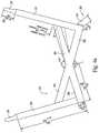
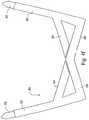
- a further aspect of the inventionrelates to a mask system including a plurality of headgear straps, a sealing assembly, and a stabilizing structure extending between the sealing assembly and at least a selected one of the headgear straps.
- the stabilizing structureis substantially rigid and has a preformed three-dimensional shape substantially matching the shape of a portion of the patient's face.
- Still another aspect of the inventionrelates to a sealing assembly for a mask system.
- the sealing assemblyincludes a mouth cushion adapted to sealingly engage around an exterior of a patient's mouth in use, and a nasal prong insert provided to the mouth cushion.
- the nasal prong insertincludes a pair of nasal prongs adapted to sealingly communicate with respective nasal passages of a patient in use and a bridging strap to interconnect the pair of nasal prongs.
- Still another aspect of the inventionrelates to a nasal prong insert including a pair of nasal prongs adapted to sealingly communicate with respective nasal passages of a patient in use and a bridging strap to interconnect the pair of nasal prongs.
- Still another aspect of the inventionrelates to a mask system for delivering breathable gas to a patient.
- the mask systemincludes a frame, a mouth cushion provided to the frame, and a pair of nasal prongs provided to the mouth cushion.
- the mouth cushionis adapted to sealingly engage around an exterior of a patient's mouth in use.
- the pair of nasal prongsis adapted to sealingly communicate with respective nasal passages of a patient in use.
- An elbowis provided to deliver breathable gas to the patient.
- a headgear assemblyis removably connected to the frame so as to maintain the mouth cushion and the pair of nasal prongs in a desired position on the patient's face.
- the headgear assemblyincludes upper headgear straps, lower headgear straps, upper stabilizing elements extending between the upper headgear straps and the frame, and lower stabilizing elements extending between the lower headgear straps and the frame.
- the upper and lower stabilizing elementsare bendable along at least one bending plane so as to conform to the shape of a portion of the patient's face.
- Yet another aspect of the inventionrelates to a method for defining a cushion shape.
- the methodincludes selecting at least three points on the cushion, defining coordinates for each of the at least three points, and smoothly transitioning the shape of the cushion between the at least three points along the cushion perimeter.
- Yet another aspect of the inventionrelates to a mask system including a plurality of headgear straps including at least upper straps, a sealing assembly, and an upper stabilizing element extending between the sealing assembly and the upper straps.
- the upper stabilizing elementincludes an elongated element having an intermediate portion attachable to the sealing assembly and end portions attachable to respective upper straps.
- Yet another aspect of the inventionrelates to an integrally molded nasal prong including a first substantially frusto-conical portion, a second substantially frusto-conical portion, and a connecting portion that interconnects the first and second conical portions.
- the connecting portionis configured to allow the first frusto-conical portion to fold into a position adjacent the second frusto-conical portion to provide a dual wall construction.
- the elbow assemblyincludes an elbow including a slot and a port, an anti-asphyxia valve adapted to be received within the slot and including a flap portion adapted to selectively close the port depending on the presence of pressurized gas, and a clip member to secure the anti-asphyxia valve to the elbow.
- the clip memberincludes a slot that is adapted to interlock with a protrusion provided to the anti-asphyxia valve.
- the clip memberhas a vertically extending rib that is located against an outer surface of the elbow when secured to the elbow. The rib is adapted to prevent assembly of the flap portion between the rib and the outer surface.
- a mask systemincluding a sealing assembly having prongs, a trampoline base provided to the prongs, headgear, and stabilizing elements between the headgear and sealing assembly.
- the trampoline baseallows the prongs to move axially.
- the prongseach have dual wall construction.
- the elbow assemblyincludes an elbow including a slot and a port, an anti-asphyxia valve adapted to be received within the slot and including a flap portion adapted to selectively close the port depending on the presence of pressurized gas, and a clip member to secure the anti-asphyxia valve to the elbow.
- the clip memberincludes a slot that is adapted to interlock with a protrusion provided to the anti-asphyxia valve.
- the clip memberhas a vertically extending rib that is located against an outer surface of the elbow when secured to the elbow. The rib is adapted to prevent assembly of the flap portion between the rib and the outer surface.
- the mask systemincludes a frame, a mouth cushion provided to the frame, a pair of nasal prongs provided to the mouth cushion, an elbow to deliver breathable gas to the patient, and a headgear assembly removably connected to the frame so as to maintain the mouth cushion and the pair of nasal prongs in a desired position on the patient's face.
- the mouth cushionis adapted to sealingly engage around an exterior of a patient's mouth in use.
- the pair of nasal prongsis adapted to sealingly communicate with respective nasal passages of a patient in use.
- the headgear assemblyincludes upper headgear straps, lower headgear straps, an upper stabilizing element extending between each upper headgear strap and the frame, and a locking clip provided to each lower headgear strap that is adapted to be interlocked with a clip receptacle provided to the frame.
- Each upper stabilizing elementis bendable along at least one bending plane so as to conform to the shape of a portion of the patient's face.
- a mask frameincluding a main body, a side frame portion provided on each lateral side of the main body, and a vent assembly provided to each side frame portion.
- Each vent assemblyincludes a plurality of holes arranged in a multi-column pattern and each column is vertically staggered with respect to one another.
- the mask systemincludes a mouth cushion structured to sealingly engage around an exterior of a patient's mouth in use, a pair of nasal prongs structured to sealingly communicate with nasal passages of a patient's nose in use, an elbow to deliver breathable gas to the patient, and a headgear assembly to maintain the mouth cushion and the nasal prongs in a desired position on the patient's face.
- the nasal prongseach include a trampoline-like base that adds flexibility to the nasal prongs in use.
- the mask systemincludes a mouth cushion structured to sealingly engage around an exterior of a patient's mouth in use, a pair of nasal prongs structured to sealingly communicate with nasal passages of a patient's nose in use, and a headgear assembly to maintain the mouth cushion and the nasal prongs in a desired position on the patient's face.
- the nasal prongseach include at least a first trampoline-like base that adds flexibility to the nasal prongs in use.
- Another aspect of the inventionrelates to a mask system including a plurality of headgear straps, a sealing assembly, and a stabilizing element extending between the sealing assembly and at least a selected one of the headgear straps.
- the selected headgear strapis adjustable with respect to the stabilizing element.
- a mask system for use between a patient and a device to deliver breathable gas to the patientcomprising a pair of nasal prongs structured to sealingly communicate with nasal passages of the patient's nose in use, each of said prongs including an inner wall and an outer wall spaced from the inner wall prior to use, said outer wall comprising a membrane that is thinner than the inner wall and no more than 0.65 mm thick.
- the mask systemincludes a pair of nasal prongs structured to sealingly communicate with nasal passages of the patient's nose in use.
- Each of the prongsincludes a thin membrane.
- the membranehas a thickness in the range of 0.1 to 0.65 mm.
- FIG. 1is a perspective view of a mask system constructed according to an embodiment of the present invention
- FIG. 2is a plan view of a first headgear section of a headgear assembly of the mask system shown in FIG. 1 ;
- FIG. 3is a plan view of a second headgear section of a headgear assembly of the mask system shown in FIG. 1 ;
- FIG. 4 ais a plan view of the first headgear section shown in FIG. 2 and showing dimensions of an embodiment and an embodiment of instruction to form the three-dimensional first headgear section and instruction where second headgear section is attached;
- FIG. 4 bis a plan view of another embodiment of the first headgear section
- FIG. 4 cis a plan view of another embodiment of the first headgear section
- FIG. 4 dis a plan view of another embodiment of the first headgear section
- FIG. 4 eis a plan view of yet another embodiment of the first headgear section
- FIG. 4 fis a plan view of still another embodiment of the first headgear section
- FIG. 5is a plan view of the second headgear section shown in FIG. 3 and showing dimensions of an embodiment
- FIG. 6is a perspective view of the mask system shown in FIG. 1 removed from the patient's head;
- FIG. 7 ais a perspective view of the headgear assembly of the mask system shown in FIG. 1 with the first and second headgear sections detached;
- FIG. 7 bis a perspective view of the headgear assembly of the mask system shown in FIG. 1 with the first and second headgear sections attached;
- FIG. 8is a rear perspective view of the mask system shown in FIG. 1 on the patient's head;
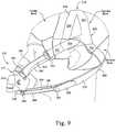
- FIG. 9is a side view of the mask system shown in FIG. 1 on the patient's head;
- FIG. 10is a rear view of the mask system shown in FIG. 1 on the patient's head;
- FIG. 11is a front view of another embodiment of a mask system on the patient's head with X, Y, and Z axes;
- FIG. 12is a side view of the mask system shown in FIG. 1 on the patient's head with X, Y, and Z axes;
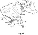
- FIG. 13is a front perspective view of the mask system shown in FIG. 1 on the patient's head with the patient pivoting a stabilizing or stabilizer strap;
- FIG. 14is an enlarged perspective view of a frame attachment member of the mask system shown in FIG. 1 being engaged with an upper headgear anchor;
- FIG. 15is an enlarged perspective view of the frame attachment member shown in FIG. 14 engaged with the upper headgear anchor;
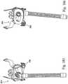
- FIG. 16is an enlarged perspective view of a frame attachment member of the mask system shown in FIG. 1 being engaged with a lower headgear anchor;
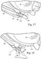
- FIG. 17is an enlarged perspective view of the frame attachment member shown in FIG. 16 engaged with the lower headgear anchor;
- FIG. 18is an enlarged perspective view of the frame attachment member shown in FIG. 16 being removed from the lower headgear anchor;
- FIG. 19is a top perspective view of an embodiment of a headgear locking clip
- FIG. 20is a bottom perspective view of the headgear locking clip shown in FIG. 19 ;
- FIG. 21is a side view of the headgear locking clip shown in FIG. 19 ;
- FIG. 22is an enlarged perspective view of the headgear locking clip shown in FIG. 19 being engaged with a clip receptacle on the frame;
- FIG. 23is an enlarged perspective view of the headgear locking clip shown in FIG. 19 engaged with a clip receptacle on the frame;
- FIG. 24is a perspective view of an embodiment of a mask system with headgear stabilizing straps attached via a press-stud type interface;
- FIG. 25is a bottom perspective view of the mask system shown in FIG. 24 on the patient's face;
- FIG. 26is a perspective view of an embodiment of a mask system with an adjustable chin support
- FIG. 27is a bottom perspective view of the mask system shown in FIG. 26 ;
- FIG. 28 ais a side view of an embodiment of a mask system with chin and cheek supports
- FIG. 28 bis a perspective view of the mask system shown in FIG. 28 a;
- FIG. 29is a rear perspective view of an embodiment of a mask system with a “scuba mask” style support
- FIG. 30is a side perspective view of the mask system shown in FIG. 1 ;
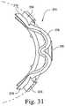
- FIG. 31is a top view of the frame of the mask system shown in FIG. 1 ;
- FIG. 32is a side view of the frame of the mask system shown in FIG. 1 ;
- FIG. 33is a top perspective view of the mask system shown in FIG. 1 ;
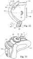
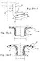
- FIG. 34 ais a cross-sectional view of an embodiment of an insertable nasal prong
- FIG. 34 bis a top perspective of a mask system including a cushion having a recess adapted to receive the insertable nasal prong shown in FIG. 34 a;
- FIGS. 34 c - 1 to 34 c - 13illustrate the trampoline effect of the nasal prong according to an embodiment of the present invention
- FIG. 34 dis a cross-sectional view of a nasal prong according to another embodiment of the present invention.
- FIG. 35is a perspective view that illustrates an embodiment of nasal prong sizes
- FIG. 36is a perspective view that illustrates an embodiment of nasal prong base sizes
- FIG. 37is a side view of another embodiment of a nasal prong in a free state
- FIG. 38is a side view of the nasal prong shown in FIG. 37 in a compressed state
- FIG. 39is a front view illustrating the nasal prong shown in FIG. 37 engaged with the patient's nose and the mouth cushion moving to the side;
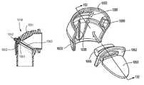
- FIG. 40is a perspective view of a mask system constructed according to another embodiment of the present invention.
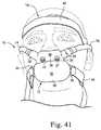
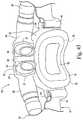
- FIG. 41is a front view of the mask system shown in FIG. 40 ;
- FIG. 42is a side view of the mask system shown in FIG. 40 ;
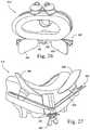
- FIG. 43is an enlarged rear view of the mask system shown in FIG. 40 ;
- FIG. 44is an enlarged bottom perspective view of the mask system shown in FIG. 43 ;
- FIGS. 45-47illustrate a mask system according to still another embodiment of the present invention.
- FIG. 48is a side view of a mask system according to another embodiment of the present invention.
- FIGS. 49-52illustrate a paired prong arrangement according to an embodiment of the present invention
- FIGS. 52B-52Eillustrate a paired prong arrangement according to another embodiment of the present invention.
- FIGS. 53-56illustrate a single prong arrangement according to an embodiment of the present invention
- FIGS. 57-58illustrate a prong including one or more ribs according to an embodiment of the present invention
- FIGS. 59-62illustrate a prong including a single wall according to an embodiment of the present invention
- FIG. 62Billustrates a single wall nasal prong having a relatively thin wall thickness with beading around a top section thereof according to an embodiment of the present invention
- FIGS. 63-65illustrate prongs having different upper section profiles
- FIG. 66illustrates a prong having varying wall sections
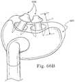
- FIG. 66Billustrates nasal prongs according to another embodiment of the present invention.
- FIGS. 67-70illustrate a prong including a dual wall according to an embodiment of the present invention
- FIGS. 70B-1 to 70B-10illustrate a paired-prong arrangement with each nasal prong including a dual-wall according to an embodiment of the present invention
- FIGS. 71-77illustrate a molding process for constructing a prong including a dual wall according to an embodiment of the present invention
- FIGS. 78-83illustrate a molding process for constructing a prong including a dual wall according to another embodiment of the present invention
- FIGS. 84-89illustrate a molding process for constructing a prong including a triple wall according to an embodiment of the present invention
- FIG. 89Billustrates a nozzle assembly including a pair of dual-wall nasal prongs according to an embodiment of the present invention
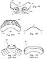
- FIG. 90is a front view of a mouth cushion according to an embodiment of the present invention.
- FIG. 91is a front view of ResMed's full face mask cushion
- FIG. 92is a front view of ResMed's mouth mask cushion
- FIG. 93is a comparison view between cushions of FIGS. 90-92 ;
- FIGS. 94-95are side and front views of the mouth cushion shown in FIG. 90 ;
- FIG. 96is a cross-sectional view through line 96 - 96 of FIG. 95 , and illustrates comparison between cushions shown in FIGS. 97-98 ;
- FIG. 97is a cross-sectional view of ResMed's full face mask cushion
- FIG. 98is a cross-sectional view of ResMed's mouth mask cushion
- FIG. 99-100are top and bottom view of the mouth cushion shown in FIG. 90 , and illustrate comparison between cushions shown in FIGS. 102 and 103 ;
- FIG. 101illustrates a membrane curvature of the mouth cushion shown in FIG. 90 ;
- FIG. 102is a bottom view of ResMed's full face mask cushion
- FIG. 103is a bottom cross-sectional view of ResMed's mouth mask cushion
- FIGS. 104-106are cross-sectional views through the mouth cushion shown in FIG. 90 , and illustrate comparison between cushion shown in FIG. 108 ;
- FIG. 107illustrates an undercushion curvature of the mouth cushion shown in FIG. 90 ;
- FIG. 108is a cross-sectional view of ResMed's full face mask cushion
- FIGS. 109-111illustrate the width of the mouth cushion shown in FIG. 90 ;
- FIG. 111Billustrates exemplary widths of the mouth cushion shown in FIG. 110 ;
- FIGS. 112-119illustrate wall cross sections along the perimeter of the mouth cushion shown in FIG. 90 ;
- FIG. 120illustrates a frame and upper and lower stabilizing elements of the mask system shown in FIG. 48 ;
- FIGS. 120B-120Fillustrate cushion attachment to the frame
- FIGS. 121-124illustrate other views of the frame and upper and lower stabilizing elements
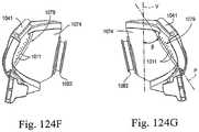
- FIGS. 124B-124Iillustrate various views of the frame including a vent assembly according to an embodiment of the present invention
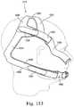
- FIGS. 125-140illustrate an elbow assembly according to an embodiment of the present invention
- FIGS. 141-143illustrate upper and lower headgear sections of the headgear assembly for the mask system shown in FIG. 48 ;
- FIGS. 144-146illustrate exemplary dimensions for large, medium, and small upper headgear sections
- FIGS. 147-149illustrate exemplary dimensions for large, medium, and small lower headgear sections
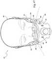
- FIGS. 150-154illustrate the headgear assembly of FIGS. 141-143 with upper and lower stabilizing elements assembled and positioned on a patient's head;
- FIG. 155illustrates the mask system shown in FIG. 48 with upper and lower stabilizing elements positioned on a patient's face
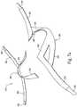
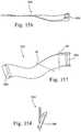
- FIGS. 156-158illustrate an upper stabilizing element according to an embodiment of the present invention
- FIGS. 158 b - 1 to 158 b - 6illustrate an upper stabilizing element according to another embodiment of the present invention
- FIGS. 158 c - 1 to 158 c - 4illustrate an upper stabilizing element and frame according to another embodiment of the present invention
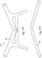
- FIGS. 159-166illustrate a lower stabilizing element according to an embodiment of the present invention
- FIGS. 167-170illustrate assembly of the lower stabilizing element shown in FIGS. 159-166 to clip receptacles provided on the frame;
- FIG. 171illustrates forces provided by the headgear assembly according to an embodiment of the present invention
- FIG. 172illustrates dimensional stability provided by the headgear assembly according to an embodiment of the present invention
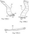
- FIGS. 173-175illustrate upper stabilizing elements according to alternative embodiments of the present invention.
- FIGS. 176-177illustrate alternative arrangements of upper stabilizing elements
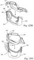
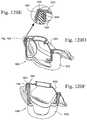
- FIGS. 178-181illustrate a headgear assembly according to another embodiment of the present invention.
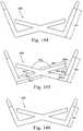
- FIGS. 182-184illustrate a lower stabilizing element according to another embodiment of the present invention.
- FIGS. 185-189illustrate a mask system according to another embodiment of the present invention.
- FIGS. 190-193illustrate an elbow according to another embodiment of the present invention.
- FIGS. 194-196illustrate a clip member according to another embodiment of the present invention.
- FIG. 197illustrates a mouth cushion with a “boomerang profile” according to another embodiment of the present invention.
- FIG. 1illustrates a mask system 210 constructed according to an embodiment of the present invention.
- the mask system 210includes a sealing assembly 212 that provides an effective seal with both the patient's mouth and the patient's nasal passages, a swivel elbow 214 to deliver breathable gas to the patient, and a headgear assembly 218 to maintain the sealing assembly 212 in a desired position on the patient's face.
- the swivel elbow 214may be replaced with an elbow that is provided to a side of the mask system, e.g., see FIG. 11 .
- the headgear assembly 218includes a first headgear section 220 and a second headgear section 230 that is attached to the first headgear section 220 .
- the first and second headgear sections 220 , 230are constructed from two-dimensional flat headgear material, e.g., soft, flexible composite material such as Breathe-O-PreneTM manufactured by Accumed Technologies Inc.
- the two-dimensional flat headgear materialis stamped, cut, or otherwise manufactured from a sheet, e.g., flexible material with thickness of 0.1-3 mm, to form the desired shapes of the first and second headgear sections 220 , 230 .
- a sheete.g., flexible material with thickness of 0.1-3 mm
- the first headgear section 220includes top strap portions 222 , bridge strap portions 224 , and crown strap portions 226 .
- the free end of each top strap portion 222includes a strip of Velcro® material 228 for use in securing the upper stabilizing straps 250 to the headgear assembly 218 , and thereby securing the sealing assembly 212 to the headgear assembly 218 .
- the dashed lines in FIG. 2represent possible joint locations of the first headgear section 220 to achieve its bowed three-dimension final form. As shown in FIG.
- the second headgear section 230includes bottom strap portions 232 and crown strap portions 234 .
- the free end of each bottom strap portion 232includes a strip of Velcro® material 238 for use in securing the lower stabilizing straps 260 to the headgear assembly 218 , and thereby securing the sealing assembly 212 to the headgear assembly 218 .
- FIGS. 2 and 3illustrate the two-dimensional first and second headgear sections 220 , 230
- FIGS. 4 a and 5illustrate dimensions of embodiments of the first and second headgear sections 220 , 230 .
- first and second headgear sections 220 , 230are shown in FIGS. 4 a and 5 , it is to be understood that these dimensions and ranges are merely exemplary and other dimensions and ranges are possible depending on application. For example, ranges that vary from those provided +/ ⁇ 10% may be suitable for particular applications.
- the two-dimensional first and second headgear sections 220 , 230are attached to one another, e.g., stitched, welded, glued or otherwise formed, to form a three-dimensional anatomically shaped headgear assembly 218 .
- the first and second headgear sections 220 , 230are attached by attaching ends of respective crown strap portions 226 , 234 .
- FIG. 6illustrates the three-dimensional headgear assembly 218 attached to the sealing assembly 212
- FIG. 7 billustrate the three-dimensional headgear assembly 218 removed from the patient's head.
- the crown strap portions 226 , 234 of the headgear assembly 218cooperate to form a round-shaped crown strap 240 that cups the parietal bone and occipital bone of the patient's head.
- the crown strap 240is preferably constructed from at least two segments of soft, flexible material that allows the crown strap 240 to conform to the shape of the patient's head. While the material may be non-elastic, in a preferred embodiment the material is elastic in order to further allow the headgear assembly 218 to conform to the patient's head shape and maybe a composite material such as Breathe-O-PreneTM manufactured by Accumed Technologies Inc.
- the bridge strap portions 224 of the first headgear section 220provides additional stability to the crown strap structure and prevent buckling.
- the bridge strap portions 224may be provided to the first headgear section 220 in multiple arrangements. For example, as shown in FIG. 4 a , the bridge strap portions 224 may be formed, e.g., punched, from the same piece of material where it remains attached between the top strap portion 222 and the crown strap portion 226 . Then, the bridge strap portions 224 may be cut away from respective top strap portions 222 and moved slightly towards respective crown strap portions 226 where it is reattached, e.g., see dashed lines in FIG. 4 a . This arrangement assists in forming the first headgear section 220 into the three-dimensional shape.
- bridge strap portions 224may not be provided on the first headgear section 220 . as shown in FIG. 4 b.
- the bridge strap portions 224may be formed, e.g., punched, from the same piece of material and attached between the top strap portions 222 and the crown strap portions 226 , and then left in its flat configuration as shown in FIG. 4 c.
- the bridge strap portions 224may be formed, e.g., punched, from the same piece of material as the top strap portions 222 and the crown strap portions 226 such that the bridge strap portions 224 are separated from respective top strap portions 222 as shown in FIG. 4 d . Then, the bridge strap portions 224 are reattached to respective top strap portions 222 to form a three-dimensional shape.
- the bridge strap portions 224may be formed, e.g., punched, separately from the top strap portions 222 and the crown strap portions 226 as shown in FIG. 4 e . Then, the bridge strap portions 224 are attached between respective top strap portions 222 and crown strap portions 226 to form a three-dimensional shape.
- the bridge strap portions 224may formed, e.g., punched, from the same piece of material as the top strap portions 222 and the crown strap portions 226 such that the bridge strap portions 224 are separated from respective crown strap portions 226 as shown in FIG. 4 f . Then, the bridge strap portions 224 are reattached to respective crown strap portions 226 to form a three-dimensional shape.
- the bridge strap portions 224may also be shortened (e.g., by cutting) if desired before reattaching depending on the particular application.
- the strap portions of the headgear assemblymay have different elasticity from one another depending on application.
- the headgear assemblymay have other suitable arrangements and forming methods.
- the straps of the headgear assemblymay be attached to one another in other locations to achieve a three-dimensional effect.
- the headgear assembly 218provides several advantages to both the manufacturer and the patient. For example, the formation of a three-dimensional crown strap 240 that fits snugly to the patient's head prevents the buckling of straps that is a recognized problem with some existing headgear. This increases the patient's comfort and provides stability to the mask system. In addition, the stability provided by the snug fit of the crown strap 240 allows the headgear assembly 218 to have a relatively small footprint. This in turn provides a relatively small surface area in contact with the patient's head, which increases comfort of the patient, e.g., prevents heat formation, areas that press against the head when being worn, sweating, etc., and reduces the visual bulk of the headgear assembly 218 .
- the formation of the crown strap 240 as described aboveremoves the need to provide adjustment on the headgear assembly 218 that is known with existing headgear, and thus no relatively hard adjustment components that can lead to patient discomfort are found. Further, the use of two-dimensional components to construct the crown strap 240 provides a relatively low-cost method of manufacturing a three-dimensional shape. However, alternative methods of manufacture such as molding from heat-setting materials or foam molded headgears are possible.
- headgear assembly 218has been described in connection with the mask system 210 , it is to be understood that the headgear assembly 218 may be used in all types of mask systems, e.g., nasal mask, mouth mask, oro-nasal mask, etc.
- upper substantially rigid stabilizing straps 250are provided between each of the top strap portions 222 and the sealing assembly 212
- lower substantially rigid stabilizing straps 260are provided between each of the bottom strap portions 232 and the sealing assembly 212 .
- the upper and lower stabilizing straps 250 , 260provide a flexible yet stable connection system between the headgear strap portions 222 , 232 and the sealing assembly 212 in order to ensure suitable tension vectors are provided to seal the sealing assembly 212 with both the patient's mouth and nasal passages.
- the desired vectors to achieve a seal to the nares and mouth regionare illustrated in FIG. 171 for example and denoted by F X and F Y specifically.
- the stabilizing straps 250 , 260are each constructed from a rigid or semi-rigid yoke section 244 that is attached to a material backing 246 , e.g., via stitching, welding, gluing, or otherwise mechanically affixed.
- the yoke section 244is manufactured from nylon or polypropylene or polycarbonate.
- the stabilizing straps 250 , 260may be constructed from multiple layers, e.g., more than two layers, or maybe constructed from a single layer of substantially rigid material.
- the stabilizing strapsmay be constructed from a relatively soft and rigid material so that a material backing is not needed.
- the sectional geometry of the yoke section 244allows flexing across the thickness, i.e., rotation around the Y-axis in FIGS. 11 and 12 , to conform to a patient's face, while preventing flexing along the longitudinal axis, i.e., no rotation around the X-axis in FIGS. 11 and 12 .
- the stabilizing straps 250 , 260act to maintain the position of the top and bottom strap portions 222 , 232 relative to each other, and secure the mask system 210 at the correct orientation on the patient's face.
- the stabilizing straps 250 , 260act as “outriggers” to the mask system 210 and provide a larger footprint on the patient's face. This arrangement substantially increases the stability of the mask system.
- each of the upper stabilizing straps 250makes an angle ⁇ of 40°+/ ⁇ 10° with respect to the horizontal plane H (as defined in FIG. 32 ) of the sealing assembly 212 .
- This angle ⁇has been chosen as the top strap portions 222 are designed to affect sealing in the roughly orthogonal planes of the nasal openings and the mouth opening of the patient. See the vectors illustrated in FIG. 171 (i.e., along these planes).
- the angle chosen and the resultant force vector when headgear tension is appliedallows for effective sealing at both the nasal prongs 270 and the mouth cushion 272 .
- the angle chosenalso takes into account the various forces the mask system 210 is subject to, e.g., the force desired to seal against the treatment pressure (as a function of sealing area), and the force desired to offset tube drag and other factors.
- each of the lower stabilizing straps 260makes an angle ⁇ of 0° to 30° with respect to the horizontal plane H (as defined in FIG. 32 ) of the sealing assembly 212 .
- the lower stabilizing straps 260are aligned in this manner so that the bottom strap portions 232 will extend close to the base of the patient's ear and remain primarily on the bony part of the patient's skull. This arrangement minimizes the sections of bottom strap portions 232 that extend horizontally over the patient's neck. In this way, the headgear assembly 218 remains firmly attached to the patient's head as there is no relative movement (e.g., distance changes) between headgear components when patient is moving or rolling around and therefore stability of the mask system 210 is maximized.
- the upper stabilizing straps 250are removably connected to an upper portion of the frame 274
- the lower stabilizing straps 260are removably connected to a lower portion of the frame 274 .
- each of the upper and lower stabilizing straps 250 , 260includes a strap attachment member 254 secured at one end and a frame attachment member 264 secured at the opposite end.
- the strap attachment member 254includes a crossbar that enables the end portion of the respective top and bottom strap portion 222 , 232 to be wrapped around, in a known manner.
- the free end of each of the top and bottom strap portions 222 , 232includes a strip of Velcro® material 228 , 238 that engages the remainder of the strap portion to adjustably pull or secure the strap attachment member 254 in place.
- the length of the top and bottom strap portions 222 , 232maybe easily adjusted. However, other adjustment arrangements are possible, e.g., adjustment via ladderlock, ratcheting mechanism, etc.
- each of the upper and lower stabilizing straps 250 , 260is in the form a swivel attachment that provides a post element 266 .
- the swivel attachment of the upper stabilizing straps 250is arranged to allow respective upper stabilizing straps 250 to rotate in one plane in order to accommodate a wide range of facial angles, as shown in FIG. 13 .
- the swivel attachment of the lower stabilizing straps 260is arranged to allow for easy engagement/disengagement.
- the frame 274includes a main body having a side frame portion 278 on each lateral side thereof.
- the main bodyincludes an aperture 280 that is coupled to the swivel elbow 214 for delivering breathable gas.
- Upper and lower anchors 256 , 258are provided on each side frame portion 278 thereof.
- each anchor 256 , 258is in the form of a female connector that provides a slot opening 262 .
- the upper anchors 256are substantially in line with the prongs when the prongs are received in the frame 274 (see arcuate dashed line).
- each frame attachment member 264is interlocked with a respective anchor 256 , 258 by moving the post element 266 adjacent the respective slot opening 262 such that the post element 266 engages within the respective slot opening 262 , e.g., with a snap-fit.
- the frame attachment members 264 on the ends of the upper stabilizing straps 250are adapted to releasably interlock with respective upper anchors 256 on the frame 274 (see FIGS. 14-15 ), and the frame attachment members 264 on the ends of the lower stabilizing straps 260 are adapted to releasably interlock with respective lower anchors 258 on the frame 274 (see FIGS. 16-18 ).
- a soft flexible finger tab 268is provided on the end of each frame attachment member 264 of the lower stabilizing straps 260 to facilitate engagement and disengagement of the frame attachment member 264 to the lower anchors 258 .
- the slot opening 262 of respective upper anchors 256is oriented towards the front of the sealing assembly 212 in order to eliminate inadvertent disengagement.
- the force on the upper stabilizing strap 250is pulling directly away from the respective slot opening 262 , and up against a solid section of the upper anchor 256 .
- the slot opening 262 of respective lower anchors 258is oriented perpendicular to the front of the sealing assembly 212 in order to allow for easy engagement/disengagement.
- This arrangementprovides the mask system 210 with a quick release system so that the mask system 210 may be removed quickly and easily from the patient's face in the event of an emergency or panic attack, as shown in FIG. 18 .
- the headgear attachment pointsi.e., anchors 256 , 258 , are located towards. the top and at the lowest point on the frame 274 , e.g., see FIG. 1 .
- This arrangementallows the stabilizing straps 250 , 260 to articulate and rotate as described above, without the stabilizing straps 250 , 260 having to bend as they run over the top of the frame 274 .
- This freedom of rotationallows the stabilizing straps 250 , 260 to conform to the patient's face.
- the frame attachment member of each of the lower stabilizing straps 260may be in the form of a locking clip 364 .
- the locking clip 364includes upper and lower arms 365 , 367 that are resiliently flexible towards one another.
- the upper arm 365includes spaced-apart protrusions 369 .
- the locking clip 364is molded in one-piece along with the yoke section 244 of the respective lower stabilizing strap 260 .
- the locking clip 364maybe formed separately from the yoke section 244 and attached thereto, e.g., by an adhesive or rotational connection, etc.
- each clip 364is interlocked with a respective clip receptacle 371 by first moving the clip 364 into the respective clip receptacle 371 such that the protrusions 369 extend through respective slots 373 with a snap fit.
- the clip 364may be released from the respective clip receptacle 371 by depressing the arms 365 , 367 towards one another until the protrusions 369 release from the slots 373 .
- the clip arrangementmay provide audible feedback when the clips 364 are attached to the respective clip receptacles 371 .
- the clip arrangementmay have other suitable designs, such as those disclosed in U.S. patent application Ser. No. 10/390,681, filed Mar. 19, 2003, U.S. patent application Ser. No. 10/655,621, filed Sep. 5, 2003, and U.S. Pat. No. 6,374,826, the contents of each being hereby incorporated by reference in its entirety.
- each of the upper and lower stabilizing straps 250 , 260may be in the form of a press-stud type interface. As shown in FIGS. 24-25 , the end of each stabilizing strap 250 , 260 includes a protruding stud 465 . A soft flexible finger tab 468 is provided on the end of each stabilizing strap to facilitate engagement and disengagement to the frame 274 .
- the frame 274is provided with stud receivers on each side frame member thereof.
- each stud 465is press-fit into a respective stud receiver.
- This arrangementallows the stabilizing straps 250 , 260 to rotate with respect to the frame 274 to allow the mask system to align on the patient's face.
- the studs 465may be provided on the frame 274 and the stud receivers may be provided on the stabilizing straps 250 , 260 .
- FIGS. 26-29illustrate alternative embodiments for stabilizing the mask system on the patient's face.
- FIGS. 26-27show a mask system 512 that includes an adjustable chin support 502 .
- the frame of the mask system 512includes an extension 504 that supports a V-shaped chin support frame 506 .
- the V-shaped chin support frame 506has two spaced elastomeric chin cushion elements 508 removably attached thereto and structured to engage a patient's chin.
- the V-shaped chin support frame 506is moveably mounted to the frame extension 504 to adjust the position of the chin cushion elements 508 relative to the patient's chin, e.g., by adjusting a thumb screw 509 .
- the chin support 502maybe adjusted in other suitable manners, e.g., via a ratchet-type mechanism, butterfly mechanism, push-button arrangement, tongue/groove arrangement, and/or gear arrangement, as described in U.S. Pat. No. 6,532,961, incorporated herein by reference in its entirety.
- FIGS. 28 a and 28 bshow a mask system 612 that includes chin and cheek supports 602 , 604 integrally formed with the cushion 672 .
- the cushion 672includes a chin support 602 that extends downwardly from a lower side wall thereof The chin support 602 is contoured to conform to the patient's chin.
- the cushion 672also includes a cheek support 604 that extends upwardly from an upper side wall thereof.
- the cheek support 604is contoured to conform to the patient's cheeks.
- FIG. 29shows a mask system 712 that includes a scuba-style support 702 integrally formed with the cushion 772 . As illustrated, the support 702 extends outwardly from a lower portion and side portions of the cushion 772 . The support 702 is, contoured to conform with chin and cheek regions of the patient's face that surround the patient's mouth.
- the sealing assembly 212 of the mask system 210includes a mouth cushion 272 structured to sealingly engage around an exterior of a patient's mouth in use and a pair of nasal prongs 270 structured to sealingly communicate with the nasal passages of the patient's nose in use and in particular the base of the patient's nares.
- the cushion 272may be integrally formed in one-piece along with the prongs 270 , e.g., by silicone in an injection molding process.
- the cushion 272is structured to be removably and replaceably attached to a substantially rigid frame 274 , e.g., by friction fit, mechanical fastening means, etc.
- the frame 274includes an aperture 280 that is coupled to the swivel elbow 214 for delivering breathable gas.
- one or more vent openingsmay be provided in the frame and/or swivel elbow for CO.sub.2 washout.
- FIGS. 1, 11, 12, and 32illustrate the frame 274 including a vent 281 .
- the vent 281may have a similar form to those disclosed in U.S. Provisional Patent Application No. 60/643,114 to Veliss, filed Jan. 12, 2005, the contents of which are hereby incorporated by reference in their entirety.
- opposing ends of the mask systemmay include cylindrical tubes 282 , one of which may be provided with a plug or vent and the other of which may be provided with an elbow 214 for delivering breathable gas.
- the positions of the elbow and plug/ventmaybe interchanged, depending on patient preference.
- the mask system(with or without cylindrical tubes 282 ) may be ventless such as the ventless design described in U.S. patent application Ser. No. 60/667,052, filed Apr. 1, 2005, the contents of which are hereby incorporated by reference in its entirety.
- a low profileis provided by sweeping back the frame 274 immediately around the prongs in order to achieve frame attachment points 256 , 258 as close as possible to the face without touching the lips.
- the frame 274is swept back in side frame portions 278 of the frame 274 such that these side frame portions 278 are about 15+/ ⁇ 5 mm below the frame height at which the frame 274 receives the prongs, i.e., the region 276 .
- This arrangementimproves the mouth cushion height to depth ratio and reduces the height of the mask system 210 on the patient's face.
- this arrangementallows the headgear attachment points 256 , 258 to be as close as possible to the patient's face. Both of these factors combine to improve stability of the mask system 210 .
- FIG. 33illustrates the position of the upper headgear anchors 256 .
- the axis A between the centers of the upper anchors 256lies centrally between the nasal prongs 270 and the upper sealing surface of the mouth cushion 272 .
- This centralized locationenables the headgear vector to radiate from these points in an orientation that is optimized for sealing both the nasal prongs 270 and mouth cushion 272 . That is, the chosen vector achieves a good balance in compressing the nasal prongs 270 to achieve a comfortable seal in the nose and compressing the mouth cushion 272 to achieve a comfortable seal at the mouth.
- this vector orientation and locationis in a plane such that the headgear stabilizing straps 250 , 260 achieve a tangential point of contact with the cheek region on the patient's face. This is advantageous for comfort.
- the use of a low profile cushion 272uses less silicone, which effectively reduces the weight of the mask system 210 . Further, the low profile design has the additional benefit of reducing the total internal deadspace volume of the mask system 210 .
- the nasal prongs 270may be formed separately from the cushion 272 , e.g., from silicone in an injection molding process, and then inserted and secured to the cushion 272 .
- the nasal prongs 270may be constructed from other suitable materials, e.g., gel material. This arrangement provides a greater scope of patient fitting by being able to select cushion size and nasal prong size independently.
- the nasal prongs 270may be independently aligned (i.e., by rotation of the prongs) with respect to the cushion 272 for optimal fit.
- FIG. 34 ashows an embodiment of an insertable nasal prong 270 .
- the nasal prong 270is a single prong that includes a nasal portion 284 that sealingly engages with a respective patient naris or nostril and a base portion 286 that is mountable to the cushion 272 , e.g., via an annular recess.
- FIG. 34 billustrates a cushion 272 with an annular recess 273 adapted to receive the base portion 286 of the prong 270 therein.
- the base portion 286 of the prong 270may be secured within the recess 273 via a press-fit or glued butt joint, for example.
- the single prong arrangementis advantageous because it allows customization of fit, e.g., more angular adjustment of the prong to match nasal angle and possibility of different sizes in each patient nostril.
- the prongs 270may be provided as a pair with a thin silicone section joining the prongs at respective base portions 286 .
- the paired-prong arrangementmay improve usability, e.g., unproved ease of assembly and alignment.
- the nasal prong 270includes a trampoline-like detail at both top and bottom horizontal segments 291 , 290 of the nasal column 288 .
- the sectional thickness, e.g., nominally 0.75 mm, of the nasal portion 284 and nasal column 288is maintained for a localized area at the base portion 286 of the prong 270 , i.e., where the nasal column 288 meets the base portion 286 (either the cushion in the case of an integral assembly or the base portion in the case of insertable prongs), before transitioning into the base portion 286 , e.g., nominally >1.5 mm.
- This sectionacts as a trampoline in use.
- the size and shape (outline) of the trampoline-like baseis closely matched, e.g., identical or close to identical in size, to that of the outer periphery 295 of the nasal portion 284 .
- the inclusion of the trampoline-like detail at the top and base of the nasal column 288has a two-fold effect.
- Second, the compression at the top and base of the nasal column 288will act as a form of suspension. In this way, the mouth cushion 272 can move away from the nasal prongs 270 , e.g., move downward or side to side, without disrupting the seal at the patient's nose. As the mouth cushion 272 moves, the nasal prongs 270 can uncompress while still maintaining sufficient load and hence seal at the patient's nose.
- the prong designmay be modified to remove the radial and vertical segments 292 , 294 .
- the inclusion of these segmentsis preferred as they maximize the trampoline effect.
- FIGS. 34 c - 1 to 34 c - 13illustrate the trampoline effect of the nasal prong in greater detail.
- FIGS. 34 c - 1 and 34 c - 2illustrate the nasal prong in its free state.
- the nasal prongincludes a nasal or head portion 284 (also referred to as a pillow), a column or stalk 288 , a base portion 286 communicated with the mouth cushion volume 287 , an upper trampoline base 297 , and a lower trampoline base 299 .
- the stalk 288transitions into the upper and lower trampoline bases 297 , 299 with radius R 1 .
- the upper trampoline base 297extends into the pillow's head portion and the lower trampoline base 299 extends into the mouth cushion volume 287 .
- the overall effectis that the trampoline bases 297 , 299 flex sufficiently so that the head portion of the pillow 284 can adjust to a height and angle to fit most nostrils.
- the change in heightmay be represented as H (height in free state) minus h (height in compressed state).
- This flexingincreases the length of the respective trampoline bases as shown in FIG. 34 c - 5 .
- L 1represents the stalk 288 and trampoline base 299 in its free state
- L 2represents the stalk 288 and trampoline base 299 in its compressed state.
- the length Le 2 of the trampoline base in its compressed or flexed stateis greater than the length Le 1 of the trampoline base in its free state.
- the extra material required to increase the length of the trampoline basescomes from the following mechanisms: the trampoline base silicone stretching, and the stalk's end rolling over and being drawn into the trampoline base as shown in FIGS. 34 c - 6 (showing upper trampoline base 297 in its free state) and 34 c - 7 (showing upper trampoline base 297 in its compressed state).
- the stalk 288has an elliptical section which does not readily roll over. When roll over does occur, resistance to this deformation will act against the stalk 288 .
- FIGS. 34 c - 3 , 34 c - 4 , 34 c - 5 , and 34 c - 7illustrate the mechanical reactions that occur when the stalk 288 rolls over. As illustrated, the transition radius between stalk 288 and trampoline base 297 , 299 increases to R 2 due to the flexible nature of the silicone. As a consequence of the radius increasing, the stalk 288 will get thinner, e.g., reduce from D to d as illustrated in FIGS. 34 c - 1 to 34 c - 7 .
- FIGS. 34 c - 6 and 34 c - 7provide dots DT to show how material moves into the trampoline base.
- FIG. 34 c - 7shows roll-over action AC and roll-over reaction RE that pulls in the stalk 288 .
- the stalk 288is a conical tube that merges at 90 degrees into the trampoline bases 297 , 299 which are conical surfaces.
- the nature of the geometrydictates that the stalk 288 is a relatively rigid member and the adjacent trampoline bases 297 , 299 are relatively flexible members.
- FIGS. 34 c - 8 and 34 c - 9when a non-axial force F is applied to the head portion of the pillow 284 creating a rotational movement to the pillow 284 , the pillow 284 will react in such a way that the trampoline base or bases 297 , 299 will rotationally flex around the relatively rigid stalk 288 .
- FIG. 34 c - 8illustrates the upper trampoline base 297 rotating about the stalk 288
- FIG. 34 c - 9illustrates the upper and lower trampoline bases 297 , 299 rotating about the stalk 288 .
- the trampoline base flexingis a combination of one side stretching and the other side buckling according to the direction of rotation.
- FIG. 34 c - 10illustrates stretching S and buckling B of the lower trampoline base 299 as the stalk 288 rotates about axis AR. Therefore, the stalk to trampoline base intersection acts as a junction for articulation.
- a trampoline base 297 , 299 provided at the top and bottom of the stalk 288equips the pillow 284 with two articulation junctions, which enables the head portion of the pillow 284 to align to most patient nostrils.
- FIGS. 34 c - 11 to 34 c - 13illustrate some possible compression and rotation scenarios for the pillow 284 .
- FIG. 34 c - 11illustrates the pillow compressed and head portion rotated causing the upper trampoline base 297 to rotate about the stalk.
- FIG. 34 c - 12illustrates the pillow compressed and head portion translated causing the stalk to rotate about top and bottom trampoline bases 297 , 299 .
- FIG. 34 c - 13illustrates the pillow compressed and head portion rotated causing upper and lower trampoline bases 297 , 299 to rotate about the stalk.
- a leaf spring 300may be provided to a base of the nasal prong 270 as shown in FIG. 34 d .
- the leaf spring 300may provide substantially similar movement and force that is provided by sections 292 and 294 shown above in FIG. 34 a , e.g. lower trampoline base.
- the insertable nasal prongs 270are provided as a pair. Moreover, the pair may be provided in any one of a number of different nasal prong sizes and may be anatomically shaped.
- the nasal prongs 270are shown in the position they would take when installed on the mouth cushion 272 .
- the section that may join each pair togetheris not shown.
- the spacing between the two nasal portions 284is substantially the same, even though the nasal portions 284 themselves are of differing sizes.
- FIG. 35illustrates three different sizes of nasal prongs 270 , i.e., small, medium, and large. As illustrated, the size of the nasal portions 284 changes, but the spacing between the nasal portions 284 remains the same.
- the size of the trampoline basematches that of the outer periphery 295 of the nasal portion 284 (see FIG. 34 a ).
- each size of pronghas the same overall base size.
- the overall base size 296(indicated in dashed lines with diameter D in FIG. 36 ) is the connector or plug that interfaces with the mouth cushion 272 .
- the overall base size 296is designed to accommodate the largest prong size, as shown in FIG. 36 .
- the axis of the prong 270aligns with the axis of the overall base 296 .
- the section on the base that remainsmay be greater than about 1.5 mm as above. This ensures that the trampoline base works similarly or identically for all sizes.
- the nasal prong 270may include an articulating portion 201 , or double prong configuration, to add flexibility and articulation of the nasal prong 270 with respect to the cushion 272 .
- the nasal prong 270is structured such that it is partially “nestable” or significantly compresses once positioned in the patient's nose.
- FIG. 37illustrates the nasal prong 270 in a free state
- FIG. 38illustrates the nasal prong 270 in a compressed state.
- compression of the nasal prong 270may be of the order of about 40%.
- the articulating portion 201is structured such that it has a substantially horizontal lower wall 202 . That is, the lower wall 202 of the articulating portion 201 is perpendicular to the lower column 203 . This allows the prong 270 to compress as the lower column 203 moves into the articulating portion 201 .
- the nasal portion 284 and upper column 204 of the prong 270are similarly structured although these are marginally stiffer than the articulating portion 201 and lower column 203 . This bias allows the articulating portion 201 and lower column 203 to compress more readily than the nasal portion 284 and upper column 204 , although compression of both sections does occur.
- the upper portion 205 of the articulating portion 201is designed to accommodate the compression of the lower column 203 , i.e., there exists sufficient height in the upper portion 205 of the articulating portion 201 so that the lower column 203 can move into this region.
- the articulating portion 201is structured such that it does not inflate and operate in an extended manner.
- the selected geometry of the articulating portion 201allows the prong 270 to compress when inserted into the patient's nose. Due to the elastic properties of the silicone (or other compressible material), this compression results in a load that assists in sealing at the patient's nose and is reacted at the frame. In effect, the prong 270 acts as a spring.
- the articulating portion 201allows additional articulation of the prong 270 relative to the frame 274 and mouth cushion 272 .
- the lower column 203compresses into the articulating portion 201 as shown in FIGS. 38-39 .
- this articulating portion 201acts as a ball-type joint.
- the geometry of this arrangementis such that the upper and lower columns 204 , 203 remain essentially undeformed with the prong 270 pivoting at the junction between the upper column 204 and the lower wall 206 , and the lower column 203 and the lower wall 202 .
- the prong 270is structured such that the lower column 203 is initially aligned with the upper column 204 . This arrangement ensures that the load desired to seal the prong 270 at the patient's nose can be effectively transferred via the headgear attached to the frame.
- the compressed prong 270acts to provide a suspension-type effect, similar to that used in vehicles.
- the mouth cushion 272can move away from the prong 270 , i.e., move downward or side to side, without disrupting the seal at the patient's nose.
- the prong 270can uncompress while still maintaining sufficient load and hence seal at the patient's nose (see FIG. 39 ).
- both the nasal portion 284 and the articulating portion 201have a substantially elliptical shape.
- the shape of the nasal portion 284ensures substantially even loading across a lower surface, and hence even loading into the patient's nose.
- This arrangementdictates that the articulating portion 201 is also elliptical in shape so that the load is transferred evenly to the nasal portion 284 .
- the prongs 270may have any other suitable shape, e.g., circular or any other closed section.
- FIGS. 40-44illustrate a mask system 10 constructed according to another embodiment of the present invention.
- the mask system 10includes a sealing assembly 12 that provides an effective seal with both the patient's mouth and the patient's nasal passages, inlet conduits 14 , 16 structured to deliver breathable gas to the patient, and a headgear assembly 18 to maintain the sealing assembly 12 in a desired position on the patient's face.
- the sealing assembly 12includes a mouth covering assembly 20 having a cushion 22 structured to sealingly engage around an exterior of a patient's mouth in use and a nasal prong assembly 24 having a pair of nasal prongs 26 structured to sealingly engage with the nasal passages of the patient's nose in use.
- the nasal prong assembly 24is supported by a side wall 32 of the mouth covering assembly 20 .
- the mouth covering assembly 20is integrally formed in one-piece along with the nasal prong assembly 24 , e.g., by silicone in an injection molding process.
- the mouth covering assembly 20 and nasal prong assembly 24may be formed separately from one another and then attached to one another.
- a standard mouth cushion sizecan be used in conjunction with a variety of nasal prong sizes reducing costs since the multiple moldings desired for different sized prongs may not be as expensive as multiple moldings for different sized mouth cushions.
- opposing ends of the nasal prong assembly 24include tubes 28 , e.g., cylindrical tubes, that are adapted to engage respective inlet conduits 14 , 16 , e.g., via friction fit.
- the tubes 28 and inlet conduits 14 , 16may have any suitable cross-sectional shape, e.g., cylindrical, elliptical, flatter section, etc.
- the inlet conduits 14 , 16are supplied with breathable gas under pressure, e.g., via an air delivery device, and the pressurized breathable gas is delivered into opposing ends of the nasal prong assembly 24 via the tubes 28 .
- the mouth covering assembly 20 and nasal prong assembly 24may be coupled such that gas is allowed to pass between each of these.
- the gasmay be allowed to pass through the nasal prong assembly 24 only, such that gas is delivered to only the patient's nasal passages.
- the mouth covering assembly 20just acts as a mouth seal.
- the gasmay be allowed to pass through the mouth covering assembly 20 only, such that gas is delivered to only the patient's mouth.
- the nasal prong assembly 24is blocked and just acts as a nasal seal.
- the cushion 22includes a non-face-contacting portion and a face-contacting portion.
- the non-face-contacting portionincludes a front wall 30 and a side wall 32 extending away from the front wall 30 .
- the front and side walls 30 , 32define a chamber for receiving the patient's mouth and a breathable gas when communicated to the nasal prong assembly 24 .
- opposing sides of the cushion 22include a crossbar 34 .
- Each crossbar 34extends from the side wall 32 and is adapted to releasably engage a lower strap of the headgear assembly 18 .
- the face-contacting portion of the cushion 22includes a membrane 36 that extends from the side wall 32 .
- the membrane 36is structured to form a seal around the lips of a patient.
- the face-contacting portionis contoured to follow generally the curvature of the patient's face.
- the face-contacting portionmay include one or more undercushions 35 (see FIG. 43 ) to provide a support structure for the membrane 36 .
- the undercushion 35may have a similar form to those disclosed in U.S. Pat. No. 6,701,927, the contents of which are hereby incorporated by reference in its entirety.
- the side wall 32 of the cushion 22supports the nasal prong assembly 24 .
- the nasal prong assembly 24includes a hollow body 38 that defines an air chamber, cylindrical tubes 28 extending from the body 38 , and a pair of nasal prongs 26 supported by a substantially flat rear wall 37 of the hollow body 38 .
- Each nasal prong 26is substantially oval in cross-section and includes a flange or widened portion 40 (also referred to as beads) at an upper end thereof (see FIG. 44 ).
- the nasal prongs 26may be angled with respect to the rear wall 37 to properly position the nasal prongs 26 with the nasal passages of the patient.
- the nasal prongs 26are in the form of nasal inserts. In use, the nasal prongs 26 are inserted into the patient's nasal passages and retained therein by respective flanges 40 .
- One or more vent ports 27may be provided in a front wall 39 of the body 38 for CO.sub.2 washout.
- the nasal prong assembly 24 and nasal prongs 26 thereofmay have a similar form to those disclosed in U.S. Pat. Nos. 6,478,026 and 6,595,215, the contents of which are hereby incorporated by reference in their entirety.
- the nasal prongs 26may be in the form of nasal pillows, nozzles, cannula, nasal puffs, and may sealingly engage with the patient's nasal passages in any suitable manner.
- the body of the nasal prong assembly 24may include one or more openings that communicate with one or more openings provided in the side wall of the cushion 22 to allow breathable gas to pass from the air chamber defined by the body 38 to the air chamber defined by the mouth covering assembly 20 .
- the components of the mouth cover assembly 20 and the nasal prong assembly 24are constructed from a substantially soft material, e.g., silicone, and may be integrally formed. However, certain components may be constructed from a substantially rigid or semi-rigid material, such as the front wall 30 , side wall 32 , and crossbars or rigid mounting loop 34 of the mouth covering assembly 20 .
- the headgear assembly 18includes an upper strap 42 removably connectable to the inlet conduits 14 , 16 and a lower strap 44 removably connectable to the sealing assembly 12 .
- the upper strap 42extends across the patient's forehead and above the patient's ears. Fastening of the upper strap 42 to the patient's head may be provided by a hook and loop material, e.g., Velcro®.
- the upper strap 42includes tube retainers 46 that are positioned adjacent the patient's ears in use. As illustrated, the tube retainers 46 retain respective inlet conduits 14 , 16 so that the inlet conduits 14 , 16 extend up and around the patient's ears.
- each tube retainer 46is a Velcro® strap that is wrapped around the respective inlet conduit 14 , 16 and upper strap 42 .
- the lower strap 44extends around the patients neck and below the patient's ears. End portions of the lower strap 44 are wrapped around a respective crossbar 34 provided on the cushion 22 and fastened in place, e.g., by a hook and loop material such as Velcro®. However, the lower strap 44 may be attached to the cushion 22 in any other suitable manner, e.g., via a clip arrangement. Also, the upper and lower straps 42 , 44 may be joined to one another, e.g., joined to one another at the back of the patient's head similar to the arrangement shown in FIG. 10 .
- the sealing assembly 12has a low profile, which improves the comfort level of the patient, and reduces the forces which may tend to pivot the sealing assembly 12 relative to the patient's face.
- FIGS. 45-47illustrate a third embodiment of a mask system 410 according to the present invention.
- Mask system 410is similar to the mask systems described above, and even includes common elements that have been indicated with similar reference numbers.
- mask system 410includes a sealing assembly 412 , a swivel elbow 414 and a headgear assembly 418 .
- the overall architecture of the headgear straps in FIGS. 45-47is similar to the overall architecture of the headgear straps in FIG. 12 .
- one main difference in the embodiment of FIGS. 45-47relates to the use of a stabilizing structure 475 .
- the stabilizing structure 475 in this examplehas one end connected to attachment member 464 provided to the frame and a second end that extends toward top strap portion 422 . The second end may be connected to a tab or extension of upper strap attachment member or buckle 454 .
- the stabilizing structure 475 , attachment member 464 , and buckle 454may be integrally as a one-piece structure. Alternatively, the stabilizing structure 475 , attachment member 464 , and buckle 454 may be formed separately from one another and then assembled to one another.
- Stabilizing structure 475has a “3D” form and is contoured to sit more flush with the face.
- the stabilizing structuresare generally “S-shaped”, and extend from the patient's temple, along the cheekbones and towards the attachment members 464 . The shape also helps to move the stabilizing structure away from the patient's eyes. Because they are generally rigid, stabilizing structures 475 can be slightly spaced from the patient's cheek region, if desired.
- the stabilizing structuresmay be made of any rigid or semi-rigid material, e.g., polycarbonate, nylon.
- the stabilizing structures 475can also be made of clear material, to minimize obtrusiveness to the patient.
- Headgear assemblymay include a padded material or soft portion 477 positioned between the stabilizing structure 475 and the patient's face.
- the stabilizing structure 475may be constructed of a relatively soft material and therefore a padded material may be unnecessary.
- Mask system 410includes a plurality of frame attachment members 464 .
- the frame attachment members 464 associated with the top strap portionsare similar to those shown in FIGS. 14 and 15 .
- the frame attachment members associated with the bottom strap portionsare similar to those shown in FIGS. 22 and 23 .
- FIG. 47also depicts a ports cap 483 for selective attachment of an oxygen delivery cannulae or the like.
- FIG. 48illustrates a mask system 1010 according to another embodiment of the present invention.
- the mask system 1010may include one or more elements that are similar to those of the mask systems described above.
- the mask system 1010includes a sealing assembly 1012 that provides an effective seal with both the patient's mouth and the patient's nasal passages, an elbow assembly 1014 , e.g., swivel elbow, and a headgear assembly 1018 to maintain the sealing assembly 1012 in a desired position on the patient's face.
- the mask system 1010enables the delivery of therapy in a manner which is unobtrusive, quiet, comfortable, and effective.
- the sealing assembly 1012 of the mask system 1010includes a mouth cushion 1072 structured to sealingly engage around an exterior of a patient's mouth in use and a pair of nasal prongs 1070 structured to sealingly communicate with the nasal passages of the patient's nose in use.
- the cushion 1072is structured to be removably and replaceably attached to a substantially rigid frame 1074 .
- the nasal prongs 1070may be formed separately from the cushion 1072 , e.g., by silicone in an injection molding process, and then inserted and secured to the cushion 1072 . This arrangement provides a greater scope of patient fitting by being able to select cushion size and nasal prong size independently.
- nasal prongsnasal pillows, nozzles, or other device that go up or seal near the patient's nose may be used.
- most peoplecan obtain a good nasal seal with at least one of three different sizes of nasal prong.
- a single sealing cushionthat seals around, e.g., just under, both nostrils may be used.
- FIGS. 49-52illustrate a paired-prong arrangement wherein nasal prongs 1070 are provided as a pair on a single insert.
- each nasal prong 1070includes a nasal portion or head portion 1084 adapted to sealingly communicate with a respective patient nasal passage and a base portion 1086 .
- the tip of each prong 1070is slightly inserted into the nose, with the head portion 1084 engaging the patient's nare.
- Each head portion 1084includes a curved area 1085 that provides lift or spring to the head portion 1084 .
- the prongs 1070are joined at respective base portions 1086 by a bridging or connecting strap 1088 , e.g., thin silicone section.
- the base portions 1086are adapted to be mounted to the cushion 1072 , e.g., via an annular recess that defines a mounting flange.
- FIG. 99illustrates a cushion 1072 with spaced-apart annular recesses that define flanges 1073 adapted to engage a respective groove provided in each of the base portions 1086 of the prongs 1070 therein.
- Each base portion 1086maybe secured within a respective flange 1073 via a interference-fit or adhesive such as glue, for example.
- the base portions 1086are mounted from the breathing chamber side of the cushion 1072 such that the bridging strap 1088 extends along an interior surface of the breathing chamber.
- the paired-prong arrangementprovides head portions 1084 that are pre-aligned with respect to one another.
- each head portion 1084has a general oval-shape with an oval-shaped nasal opening (see FIG. 50 ).
- the pair of head portions 1084may be angled with respect to one another to provide a better fit with the patient's nares.
- the head portions 1084may define an angle A therebetween of about 50°-60°, e.g., 54°.
- other anglesare possible and may be customized based on the patient.
- the paired-prong arrangementprovides correct alignment with the mating cushion 1072 and with the patient's nares.
- the head portions 1084are pre-angled to match the patient's nares
- the base portions 1086match the oval shape of the flanges 1073
- the connecting strap 1088may flex or bend to find its position.
- the major axes of the elliptical head portions 1084may be parallel to each other, e.g., molded parallel to one another.
- the bridging strap 1088may have a circular cross-section (see FIG. 52D ).
- the bridging strap 1088is flexible or bendable to achieve the desired angle. The patient can vary the angle for either the left or right prong, which allows customization.
- the bridging strap 1088prevents individual left and right prongs 1070 from becoming separated and lost.
- the symmetrical design(as the left and right prongs 1070 are molded parallel) enables easier assembly onto the cushion. This arrangement also allows the insert to be inserted into the cushion in different orientations, one being rotated 180° from the other.
- the paired-prong arrangementprovides correct alignment with the mating cushion 1072 and with the patient's nares because each prong is held in angular alignment with respect to the other prong by nature of its connection with the other prong. Also, the paired-prong arrangement prevents accidental loss of component, e.g., loss of nasal prongs. In addition, the paired-prong arrangement may improve ease of assembly.
- the prongs 1070may be configured such that the paired-prong insert can be inserted into the cushion 1072 in from either the breathing chamber side or the outward facing side, for error proofing.
- FIGS. 53-56illustrate a single-prong arrangement wherein a nasal prong 1070 is molded and assembled individually to the cushion 1072 .
- the nasal prong 1070includes a head portion 1084 and a base portion 1086 adapted to be mounted to the cushion 1072 , e.g., via a press-fit or adhesive.
- each nasal prong 1070maybe independently aligned with respect to the cushion 1072 for optimal fit, e.g., angular adjustment of each prong to match nasal angle.
- the single prong arrangementprovides the possibility of different prong sizes in each patient nare, e.g., large prong size for left nare and small prong size for right nare.
- one or more ribs 1090may be integrally molded with each nasal prong 1070 to provide axial and radial spring and/or lateral/circumferential structural rigidity/reinforcement, e.g., increased radial strength.
- multiple ribs 1090are located internally on the upper section of the nasal portion or head portion 1084 .
- the multiple ribs 1090provide increased radial strength to allow the use of thin walled head portion 1084 without collapsing. In this way, the head portion 1084 can inflate to a certain degree, to match nasal opening shape, but still retain sufficient rigidity to allow insertion into the nasal opening.
- Each rib 1090may be attached or unattached at its base (adjacent the curved area 1085 ) to control spring rate and stiffness.
- the cross-sectional thickness of each rib 1090e.g., rib profile, may vary along its length to control spring rate and stiffness.
- ribsare particularly advantageous where the cushion is formed from a very thin and/or very flexible membrane.
- FIGS. 59-62illustrate another embodiment of a nasal prong 1070 having a single-wall head portion 1084 .
- the base portion 1086 of the nasal prong 1070includes a slot 1092 to facilitate assembly to the cushion 1072 .
- the upper flange that defines the slot 1092e.g., a circumferential groove
- the lower flange that defines the slot 1092includes a chamfered surface 1096 . This arrangement provides a tapered lead-in to allow easier assembly to the cushion 1072 .
- the section of the nasal prong 1070(where the nasal column 1087 meets the base portion 1086 ) provides axial spring and compression (e.g., similar to a shock absorber) to compensate for slight variation in angle and distance between the cushion and the patient's nares.
- this sectionprovides a trampoline-type arrangement that allows the nasal column 1087 to move axially into the base portion 1086 . This forms a kind of ball joint which accommodates both short and large axial distances to the patient's nares.
- the upper section profile of the head portion 1084may be varied to better accommodate nares of different patients.
- the upper section profilemay have a convex shape (as shown in FIG. 63 ), a straight shape (as shown in FIG. 64 ), or a concave shape (as shown in FIG. 65 ).
- the head portion 1084may be formed of a deformable material, e.g., foam, so that the head portion 1084 maybe deformed to conform to a patient's nare.
- FIG. 66illustrates a head portion 1084 having one wall section (the left side) that is thicker than an opposing wall section.
- nasal prongsare longer than those known in the art, e.g., nasal prongs disclosed in U.S. patent application Ser. No. 10/781,929, filed on Feb. 20, 2004, the entirety incorporated herein by reference. This increased length is desired for a number of reasons.
- the length of the nasal prongis desired to “reach” to the back of the patient's nose. This is due to the presence of the mouth cushion which spaces the base of the prongs from the patient's face. Specifically, the base of the prongs is positioned “behind” the membrane and undercushion that seal on the patient's upper lip. Thus, the prongs must be longer to extend from the mouth cushion to the patient's nose. In contrast, the nasal prong of the '929 application sits very close to the patient's face so its length is shorter.
- the length of the nasal prongis desired to ensure that sealing on all facial geometries can be satisfied, i.e., to match varying naso-labial angles.
- the mouth cushionprecludes rotation of the device to match naso-labial angles. Due to the height of the mask, rotation would result in a large change in distance at the bottom of the mouth cushion, which would present a sealing challenge.
- the prongsare provided on a “barrel” that can be rotated to match varying naso-labial angles.
- the additional length of the nasal prong sectionallows greater compression than that achievable in the '929 application. This in turns provides additional sealing at the nose and assists in achieving an appropriate balance of nose and mouth sealing. In addition, compression at the base of the column will act as a form of “suspension”. In this way, the mouth cushion can move away from the prong section (i.e., move downward or side to side) without disrupting the seal at the nose. As the mouth cushion section moves, the prong section can uncompress while still maintaining sufficient load and hence seal at the nose. This is not provided in the '929 application as the absence of a mouth cushion means the device is much more difficult to disrupt on the face.
- the column or stalk 1087has a length in the range of 9-20 mm. In a preferred embodiment, the stalk 1087 has a length of 12 mm.
- nasal prongs 1070 in their free statemaybe inset into the mouth cushion 1072 as shown in FIG. 66B .
- the prongs 1070 shown in FIG. 66Bmay have a length of up to 70 mm.
- PCT Application No. PCT/AU2004/001832filed Dec. 24, 2004, which is incorporated herein by reference in its entirety.
- the prong arrangement of the present inventionprovides independent movement of both ends of the “stalk” or nasal column of the prong.
- the head portion or pillow sectioncan articulate independent of the base portion or “trampoline” section.
- This form of independent suspensionallows both axial and rotational movement of the top of the prong. It also allows for the head portion and base portion to remain parallel despite movement or bending of the stalk.
- the prongsare designed to articulate at both ends.
- the geometry usedallows the joints at each end to act much like “ball in socket” joints and conform to different facial geometries.
- the additional length of the prongsallow this articulation (rotation of the prong around its base) without the underside of the prong interfering with the mouth cushion.
- FIGS. 67-70illustrate a nasal prong 1070 having a dual or double-wall head portion 1084 .
- the head portion 1084includes an inner wall 1002 and an outer wall 1004 that surrounds the inner wall 1002 .
- the outer wall 1004is substantially thinner than the inner wall 1002 , and no more than 0.65 mm thick.
- the inner and outer walls 1002 , 1004are molded in its in use position. In use, the thin outer wall 1004 inflates and/or allows conformance to the inner periphery of the patient's nare to enhance the seal of the head portion 1084 against the patient's nare.
- the dual wall nasal prongmay reduce the time of mask set-up as it provides more ability to seal, e.g., thin outer wall conforms to the patient's nasal contours.
- An early generation dual-wall nasal prongis disclosed in PCT Application No. PCT/AU2004/001832, filed Dec. 24, 2004, which is incorporated herein by reference in its entirety.
- a dual-wall nasal cushionis disclosed in U.S. Pat. No. 6,112,746, which is incorporated herein by reference in its entirety.
- the thin outer wall 1004(also referred to as an outer membrane) may have a thickness in the range of 0.1 mm to 0.65 mm. In a preferred embodiment, the thin outer wall 1004 has a thickness of 0.35 mm. In contrast, the inner wall 1002 (also referred to as an inner membrane) has a thickness of about 0.75 mm, which is substantially similar to the thickness of the base 1086 and the column or stalk 1087 . In other arrangements, it would also be possible to eliminate the inner wall, just leaving the thinner outer wall membrane for contact with the patient.
- the outer wall 1004is relatively thin to provide compliance and/or conformance with the patient's nose to enhance the seal of nasal prong 1070 . That is, the thinner outer wall 1004 allows superior sealing due to its ability to conform to the nasal contours.
- the thicker inner wall 1002supports the thinner outer wall 1004 as the prong 1070 is inserted and/or engaged with the patient's nose, e.g., so the outer wall 1004 does not collapse.
- the prong 1070is pressurized, the outer wall 1004 conforms to the patient's nose and the inner wall 1002 “floats” under the patient's nose, e.g., spaced from the outer wall 1004 .
- An adequate gape.g. 0.75 mm, is provided between the inner wall 1002 and the outer wall 1004 to allow movement of the inner wall 1002 without disturbing the seal of the outer wall 1004 .
- the gap between the inner and outer walls 1002 , 1004may vary around the perimeter of the head portion 1084 in use, e.g., depending on set-up and/or movement during use.
- the relatively thin wall thicknesse.g. 0.35 mm
- the thin wall thicknessis preferably provided to an outer wall of a dual-wall prong configuration.
- the thin wall thicknessmay be provided to a nasal prong having a single wall configuration.
- the thin membraneallows superior sealing due to its ability to conform to the patient's nasal contours.
- a nasal prong having a single wall head portionmay have a wall thickness in the range of 0.1 mm to 0.65 mm, e.g., preferably 0.35 mm.
- the thin head portion 1084may include a thicker top section or bead 1089 to prevent excessive flash and/or tearing as the nasal prong 1070 is removed from its mold.
- the head portionmay include other structure to prevent excessive flash and/or tearing.
- one or more internal ribsmay be added to the head portion 1084 , e.g., in lieu of or in addition to beading 1089 .
- ribs 1090may be provided to a thin, single wall head portion 1084 .
- a single wall head portionmay be provided with a tapered or varying cross-section along its length, e.g., wall thickness tapers from relatively thin to thick.
- a thin outer membranemay be provided as a separate component that is retro-fit (attached, coupled, glued, etc.) to a single wall nasal prong.
- a thin outer membranemay be provided to an exterior surface of the head portion and secured in position, e.g., by an elastic ring.
- the other membrane 1004need not be made of the same material (e.g., Silicone) as the inner wall 1002 , so long as it is patient friendly and compliant.
- the head portion 1084 of the dual wall nasal prongincludes a substantially straight conical section s 1 that ramps down to a relatively large elliptical or curved section s 2 , e.g., see FIG. 70 .
- the curved sectionis configured to match the patient's nares opening at the bottom, the conical section improves insertion into the patient's nose, and dual-wall configuration achieves a quicker more effective seal. That is, this profile arrangement has the ability to locate or insert the head portion into the nose easier, which optimizes set-up time. In use, patients may establish a seal about halfway up the head portion.
- This profile arrangementmay also be provided in a single wall nasal prong, e.g., see FIG. 62 .
- the base portion 1086 , stalk 1087 , head portion 1084 , and opening 1069each include oval or elliptical shapes when viewed in plan view, e.g., see FIG. 68 .
- other shapesare possible depending on application, e.g., shape of the patient's nose.
- the base portion, stalk, head portion, and/or openingmay have a circular shape.
- the nasal prongmay be configured such that portions of the prong transition from elliptical to circular shapes, e.g., base portion of the head portion may be generally circular and the head portion and outlet openings may be elliptical and the prong transitions therebetween.
- the dual wall nasal pronghas an outer wall 1004 that is longer than the inner wall 1002 , e.g., see FIGS. 67 and 70 .
- This arrangementmay help with sealing and may assist in removal of the dual wall nasal prong from the molding tool.
- the outer wall 1004may be of an equivalent length or shorter than the inner wall 1002 .
- a surface finishmay be added to one or more surfaces of the dual-wall nasal prong.
- the surface finishmay help in removing the nasal prong from its molding tool.
- the surface finishmay help with sealing.
- a surface finishmay be provided on the inner surface of the outer wall 1004 to assist removal of the nasal prong from the tool, e.g., a sliding core.
- a surface finish provided on the outer surface of the outer wall 1004may also help removal of the nasal prong from the tool and may assist sealing with the patient's nare.
- a surface finishmay be provided on the inner and/or outer surface of the inner wall 1002 to help removal of the nasal prong from the tool.
- beading around the top periphery of the outer wall 1004may be applied to prevent excessive flash and/or tearing on removal from the tool.
- the molding toolitself may include surface finish, e.g., frosted surface finish, to facilitate removal from the nasal prong.
- a surface finishmay be added to molding tool surfaces that engage the inner surface of the outer wall 1004 and/or the outer surface of the inner wall 1002 .
- the entire exterior surface or portions. of the exterior surface of the toolmay have a surface finish.
- the base portion 1086 of the dual-wall nasal prongis similar to that of the nasal prong having a single-wall, e.g., slot 1092 , rounded upper flange 1094 , chamfered lower flange 1096 , and axial spring section.
- the base of the dual-wall nasal prongmay have other suitable constructions, e.g., such as the base shown in FIGS. 55, 56, and 58 .
- the nasal prongincludes upper and lower trampoline-like bases that provide articulation, a self-adjusting length, and a force for sealing.
- the trampoline-like baseincludes two curved sections at the top and bottom thereof, and a straight section at the middle thereof. This structure provides the nasal prong with a form of suspension.
- the trampoline base detailis provided at both ends of the stalk.
- the trampoline base detailacts as a universal mechanism to articulate and align the head portion of the pillow to the patient's alar and nasolabial angles, self-adjust the stalk length to suit the patient's nasolabial height, and/or provide a comfortable sealing force to the nares. That is, the trampoline base detail allows rotation of the stalk relative to both the head portion of the pillow and the base portion, and allows reduction in height of the head portion of the pillow relative to the base portion.
- FIGS. 70B-1 to 70B-10illustrate a paired-prong arrangement wherein nasal prongs 1070 are provided as a pair on a single insert. As illustrated, each nasal prong 1070 includes dual-wall head portion such as that described above in FIGS. 67-70 . The prongs 1070 are joined at respective base portions by a bridging or connecting strap 1088 .
- FIGS. 70B-1 to 70B-10illustrate exemplary dimensions for a paired prong arrangement, e.g., medium size.
- D 1is 10.5 mm
- D 2is 22.5 mm
- D 3is 33.6 mm
- D 4is 38.9 mm
- D 5is 41 mm
- D 6is 8 mm
- D 7is 10.3 mm
- D 8is 25.1 mm
- D 9is 4.6 mm
- D 10is 7 mm
- D 11is 20.1 mm
- D 12is 14.2 mm
- D 13is 9.4 mm
- D 14is 66.45 mm
- D 15is 24.5 mm.
- specific dimensionsare provided, it is to be understood that these dimensions are merely exemplary and other dimensions are possible depending on application.
- the exemplary dimensionsmay vary by 10-20% or more or less depending on application.
- each prong 1070are relatively flash free.
- the outer wall 1004is relatively free from partlines and flash.
- the free end of the outer wall 1004is smooth and has a rounded edge, e.g., no sharp edges, and relatively free from flash and tears.
- the entire paired prong arrangementmay be mirror polished, although some selected surfaces may have a non-polished surface finish, e.g., inner surface of outer wall.
- one of the inner and outer wallsmay be molded in an open position and then inverted to form the dual wall construction. This arrangement simplifies the molding process.
- the inner wall 2502may be molded in an open position (as shown in FIGS. 71-74 ), and then inverted internally to form the dual wall construction (as shown in FIGS. 75-77 ).
- the wall sectionmay be varied to control stiffness/rigidity.
- one walle.g., inner wall 2502
- an integrated hinge 2506may be provided between the walls 2502 , 2504 to control the fold-over location.
- FIGS. 78-83illustrate an alternative arrangement wherein the outer wall 2604 may be molded in an open position (as shown in FIGS. 78-80 ), and then inverted externally with respect to the inner wall 2602 to form the dual wall construction (as shown in FIGS. 81-83 ).
- the wall sectionmay be varied to control stiffness/rigidity (e.g., inner wall 2602 (e.g., 0.7 mm) thicker than outer wall 2604 ).
- the outer wall 2604acts like a “tacky” filler between the head portion 1084 and the patient's nare.
- FIGS. 84-89illustrate a nasal prong 1070 having a triple-wall construction.
- the nasal prong 1070may have other suitable multi-wall constructions, e.g., head portion 1084 with two or more walls.
- first and second outer walls 2704 , 2705may be molded in an open position (as shown in FIGS. 84-86 ), and then inverted externally with respect to inner wall 2702 to form the triple wall construction (as shown in FIG. 87-89 ).
- the wall sectionmay be varied to control stiffness/rigidity.
- the fold linesmay be positioned differently to achieve a different length fold-over portion.
- the dual wall arrangementfacilitates sealing of the nasal prong in the nares by combining a structure-defining thicker wall with a seal-forming thinner wall.
- a very thin wallwhile suitable for forming a seal, may lack sufficient stiffness by itself to support the necessary structure in use. As discussed above, adding ribs can stiffen a wall otherwise too thin to support itself in use.
- the dual-wall nasal prongmay be incorporated into other mask systems.
- the dual-wall nasal prongmay be incorporated into a nozzle assembly such as that disclosed in U.S. patent application Ser. No. 10/781,929, filed Feb. 20, 2004, the entirety incorporated herein by reference.
- FIG. 89Billustrates an embodiment of such an arrangement.
- the nozzle assembly 2810includes a base portion 2811 and a pair of dual-wall nasal prongs 2870 provided thereto.
- the base portion 2811is adapted to be attached to a frame as described in the '929 application.
- each dual-wall nasal prong 2870includes a head portion 2884 having an inner wall 2802 and an outer wall 2804 .
- the outer wall 2804may have a surface finish applied to improve manufacturability.
- the mouth cushion 1072includes a non-face-contacting portion 1038 and a face-contacting portion 1040 .
- the non-face-contacting portion 1038is structured to be removably and replaceably attached to the frame 1074 .
- the non-face-contacting portion 1038includes an arrow-head type design having a tapered end portion 1042 with a sealing lip 1044 .
- the tapered end portion 1042is adapted to be easily inserted and retained, via a retaining bead 1049 , within a channel 1075 provided on the frame 1074 (see FIGS. 121, 167, and 120B-120F ).
- the sealing lip 1044provides a seal around the perimeter of the cushion 1072 and also retains the cushion 1072 onto the frame 1074 .
- alignment featurese.g., diamonds or triangles or other details, maybe provided on the cushion 1072 and frame 1074 to aid correct assembly.
- Cushion attachment to the framemay be similar to that disclosed in U.S. application Ser. No. 10/390,682, which is incorporated herein by reference in its entirety. However, other cushion attachment methods are possible.
- the face-contacting portion 1040 of the cushion 1072includes a side wall 1046 , an undercushion 1047 extending away from the side wall 1046 , and a membrane 1048 provided to substantially surround the undercushion 1047 and provide a sealing structure for the face-contacting portion 1040 .
- the inner edge of the membrane 1048defines an aperture that receives the patient's mouth.
- the side wall 1046includes spaced-apart prong support structures 1045 that provide annular recesses 1073 adapted to support respective prongs 1070 (e.g., see FIGS. 94, 96, 112, and 113 ).
- the prong support structures 1045provide an angled pedestal that project the prongs at the correct angle to the patient's nares.
- FIGS. 90-98illustrate the shape of the cushion 1072 with respect to ResMed's full face mask cushion 1200 (shown in isolation in FIGS. 91 and 97 ) and ResMed's mouth mask cushion 1300 (shown in isolation in FIGS. 92 and 98 ).
- the cushion 1072has a different shape in the lower chin region when viewed from the front and the side.
- the cushion 1072is “squarer” (height to width ratio different) at the lower chin region and lower corners of the patient's mouth (area indicated by dots D) when viewed from the front as shown in FIG. 93 , as compared to ResMed's full face mask cushion 1200 which is more curved.
- This shape of the cushion 1072covers more of the lower chin region as indicated by the hatched region in FIG. 93 .
- this shape of the cushion 1072better accommodates variations in facial curvature in the chin region based on anthropometric data.
- this shape of the cushion 1072seals around deep lines radiating from the mouth often found on older patients. This provides a better seal when mouth movements occur during sleep.
- This change in shape in the lower chin region(area indicated by dot D) is also illustrated when viewed from the side as shown in FIG. 96 .
- the cushion 1072is asymmetric about the axis of the mouth (see FIG. 90 ), whereas ResMed's mouth mask cushion 1300 is symmetrical about the axis of the mouth (see FIG. 92 ). Also, the cushion 1072 has a smaller outer radius in the chin region (shown as rl in FIG. 90 ) than the outer radius in the upper lip region (shown as ru in FIG. 90 ).
- FIGS. 99-103illustrate the shape of the cushion 1072 with respect to ResMed's full face mask cushion 1200 (shown in isolation in FIG. 102 ) and ResMed's mouth mask cushion 1300 (shown in isolation in FIG. 103 ).
- the membrane 1048 of the cushion 1072is similar in curvature at the chin and upper lip regions when compared to ResMed's full face mask cushion 1200 at the chin area.
- the curvature of the cushion membrane 1048 at the chinis substantially similar or the same as the curvature of the cushion membrane 1048 at the upper lip region (when viewed from the top as shown in FIG. 99 ).
- this curvature of the cushion membrane 1048includes a concave parabolic center region C and two convex curved side regions S joined to the side walls of the cushion 1072 .
- This arrangementis in contrast to the curvature of ResMed's mouth mask cushion 1300 which is defined by a shallower radius (see FIGS. 99 and 100 ).
- FIGS. 104-108illustrate the shape of the undercushion 1047 with respect to ResMed's full face mask cushion 1200 (shown in isolation FIG. 108 ).
- ResMed's mouth mask cushion 1300does not include an undercushion.
- the undercushion 1047is the same or similar in curvature at the chin and upper lip regions to ResMed's full face mask undercushion 1200 .
- the curvature of the undercushion 1047 at the chin regionis the same or similar to the curvature of the undercushion 1047 at the upper lip region (as viewed from the top in FIG. 104 ).
- This curvatureis illustrated in FIG. 107 and includes a substantially flat center portion C and angled side portions S.
- the center and side portionsare joined together by curved/radii portions R 1 .
- the side portions Smerge into a second smaller radius R 2 where the cross-sectional cut has been made.
- the width of the undercushion 1047 and the membrane 1048 at the upper lip regionis less than the width of the undercushion 1047 and the membrane 1048 at the chin region.
- the width of the undercushion 1047 in the upper lip regionis smaller such that it fits in the relatively narrow region between the nares and the upper lip (see FIG. 111 ) and anthropometric variations in patient population.
- the width of the undercushion 1047 and membrane 1048 at the upper lipis between 20% to 80% of the width of the undercushion 1047 and membrane 1048 at the chin region.
- dimension Amay be about 4 mm
- dimension Bmay be about 6 mm
- dimension Cmay be about 8.8 mm
- dimension Dmay be about 11 mm.
- the cross-section of the cushion 1072varies along the perimeter of the cushion 1072 .
- cross-sections A, B, and Care provided in upper lip, side, and chin regions of the cushion 1072 .
- the cross-section Bis symmetrical on both sides of the cushion 1072 .
- alternative embodimentsmay utilize more than three cross-sections.
- Elements that define each cross-section A, B, and Cinclude angles .beta. and .alpha. between the cushion side wall 1046 and the tip of the undercushion 1047 and the tip of the membrane 1048 , respectively (see FIG. 117 ), widths W.sub. 1 and W.sub. 2 from the cushion side wall 1046 to the tip of the undercushion 1047 and membrane 1048 , respectively (see FIG. 118 ), heights H.sub. 1 and H.sub. 2 from the top of the cushion side wall 1046 to the tip of the undercushion 1047 and membrane 1048 , respectively (see FIG.
- the undercushion 1047 and membrane 1048 of the illustrated embodimentsalso include straight portions s 1 and s 2 , respectively, at some cross-sections. However, other elements maybe included to define each cross-section.
- the shape or profile of the cushion 1072may be defined by three points selected at common points of each of the three cross-sections. At each of the three points, x, y, and z coordinates are defined, where x dimensions are measured from an anthropometrical datum, y dimensions are measured from a vertical symmetry line, and z dimensions are measured from the cushion height.
- the shape of the cushion 1072smoothly varies between the three points along its perimeter.
- the frame 1074includes a main body 1076 having a side frame portion 1078 on each lateral side thereof.
- the main body 1076includes an aperture 1080 and a flanged collar member 1082 that surrounds the aperture 1080 .
- the elbow assembly 1014is coupled to the flanged collar member 1082 in a manner as described below.
- the frame 1074also includes the channel 1075 for retaining the cushion 1072 as described above.
- a vent assembly 1079is provided in each side frame portion 1078 . of the frame 1074 for CO 2 washout.
- the vent assemblymay be configured such as those disclosed in U.S. Provisional Patent Application No. 60/795,615, entitled “Nasal Assembly” and filed Apr. 28, 2006, which is incorporated herein by reference in its entirety.
- one or more vent openingsmay be provided in the swivel elbow 1014 for CO 2 washout.
- each vent assembly 1079is provided in each side frame portion 1078 of the frame 1074 , adjacent the upper anchors 1041 described below.
- Each vent assembly 1079includes an array or pattern of relatively small holes 1011 arranged in a plurality of columns, e.g., 3-10 columns, and in the example illustrated, 5 columns. The 5 columns are vertically staggered with respect to one another.
- the first hole in each columncooperate to form an axis A that is angled at an angle .alpha. (when viewed from the front as shown in FIG. 124E ) of about 15-35.degree., e.g., 25.degree., with respect to vertical axis V.
- an angle .alpha.when viewed from the front as shown in FIG. 124E
- 15-35.degree.e.g., 25.degree.
- each holeis provided along a plane P (approximate plane shown in FIG. 124G due to frame angle in side view) that forms an angle .beta. of about 20-40.degree., e.g., 30.degree., with respect to vertical axis V.
- each holehas a longitudinal axis L that is angled at an angle of about ⁇ 10.degree. to 45.degree., e.g., 0.degree., with respect to transverse axis T.
- Each columnincludes 2-6 holes, e.g., 4 holes.
- each hole 1011has a generally part conic shape, including opposed walls that converge from a larger diameter to a smaller diameter, as viewed in the direction of exhausted gas.
- the smaller diametermay be about 0.7 mm
- the larger diametermay be about 1 mm
- the included angle of the conemay be about 10.degree.
- the height of the conemay be about 1.7 mm.
- other vent arrangementsare possible.
- the holes 1011are located away from the aperture 1080 to avoid air flow interference. Also, the holes 1011 are located near headgear attachment points where the frame 1074 is relatively flat to the users face for the anchor structures. In addition, the holes 1011 are positioned on relatively flat portions of the frame 1074 so that air may be vented perpendicularly from the general plane of the patient's face to avoid air jetting towards a bed partner.
- this vent arrangementoptimizes mask operation and is synergistic in that it utilizes an area of the frame 1074 which is relatively flat to the patient's face for two purposes, i.e., anchor structure and perpendicular venting. Aesthetics of the frame 1074 are also improved significantly by reducing the number of relatively flat areas that are provided on the frame 1074 .
- Each side frame portion 1078includes upper and lower anchors 1041 , 1043 for attaching the headgear assembly 1018 .
- each upper anchor 1041is in the form of a female connector that provides a slot opening 1062
- each lower anchoris in the form of a clip receptacle 1071 . Attachment of the frame 1074 to the headgear assembly 1018 will be described in greater detail below.
- the frame 1074provides four anchor points (as shown in FIGS. 120 and 167 ) for securing the mask system 1010 onto the patient's face. As illustrated, the anchor points are located at the vertical and horizontal extremities of the frame 1074 to provide maximum stability by acting as “outrigger” elements.
- the elbow assembly 1014e.g., swivel elbow, includes an elbow 1051 , an anti-asphyxia valve (AAV) 1052 , and a clip (or support) member 1053 to secure the AAV 1052 to the elbow 1051 .
- AAVanti-asphyxia valve
- the elbow 1051includes a first portion 1081 connectable to the frame 1074 and a second portion 1083 connectable to an air delivery tube 1008 (see FIGS. 48, 155, and 120 ).
- the first portion 1081 of the elbow 1051is releasably connected to the flanged collar member 1082 of the frame 1074 in a snap-fit manner as is known from U.S. Patent Application Publication No. 2003/0196656, which is incorporated herein by reference in its entirety.
- the elbow 1051also includes a slot 1091 to receive the AAV 1052 , a port 1093 that is selectively closed by a flap portion 1063 of the AAV 1052 (depending on the presence of pressurized gas), and two recesses or protrusions (not visible) for attaching the clip member 1053 with a snap-fit.
- the port 1093may be divided into two sub-ports by a member 1098 .
- the AAV 1052interlocks with the clip member 1053 to provide a sub-assembly that is removably attached to the elbow 1051 with a snap-fit.
- the AAV 1052e.g., constructed of flexible silicone or other elastic material, includes an arrowhead-shaped protrusion 1095 that removably interlocks with a slot 1097 provided on the clip member 1053 , e.g., constructed of rigid plastic.
- the inside edges of the slot 1097are filleted to allow for easier assembly of the AAV 1052 .
- the arrowhead shape of the protrusion 1095facilitates assembly.
- the inside edges of the slot 1097may have a conical fillet or chamfer, for example, to facilitate assembly.
- the protrusion 1095 of the AAV 1052may have a filleted, curved, chamfered, or tapered end to facilitate assembly.
- the clip member 1053includes two tabs 1099 that interlock with respective recesses/protrusions (not shown) provided to the elbow 1051 .
- the clip member 1053includes structure to prevent incorrect assembly of the AAV 1052 to the elbow 1051 .
- the clip member 1053includes recessed sides 1033 and a central vertical rib 1035 integrally molded with the clip member 1053 .
- the recessed sides 1033 and central vertical rib 1035are located against the elbow outer surface 1037 , e.g., flush against the elbow outer surface, to prevent the AAV 1052 from being assembled between the clip member 1053 and the elbow 1051 .
- the clip member 1053is assembled to the elbow 1051 with the AAV 1052 in an incorrect orientation (as shown in FIG. 140 and in dashed lines in FIGS.
- the flap portion 1063 of the AAV 1052will be positioned between the central vertical rib 1035 and the elbow outer surface 1037 , which prevents the clip member 1053 from interlocking with the elbow 1051 . It would then be evident to a user that the AAV 1052 had not been correctly installed.
- the flap portion 1063 of the AAV 1052is longer than the clip member 1053 is wide such that if the AAV 1052 is incorrectly assembled, the flap portion 1063 will extend outside of the clip member 1053 and thereby provide a visual and tactile cue to the patient that the AAV 1052 has been incorrectly assembly to the elbow 1051 .
- materiale.g., wall thickness
- material surrounding the port 1093 of the elbow 1051may be cut-away to reduce material. However, sufficient material is maintained to allow surface area for engaging the flap portion 1063 of the AAV 1052 in use.
- elbow assembly 1014Alternative embodiments of the elbow assembly 1014 are disclosed in PCT Application No. PCT/AU2006/000031, which is incorporated herein by reference in its entirety.
- the headgear assembly 1018includes an upper headgear section 1020 and a lower headgear section 1030 that is attached to the upper headgear section 1020 .
- Upper stabilizing elements 1050are provided between the upper headgear section 1020 and the frame 1074
- lower stabilizing elements 1060are provided between the lower headgear section 1030 and the frame 1074 .
- the headgear assemblypreferably includes elastic straps, e.g., a pair of upper and a pair of lower elastic straps, and preferably includes the rigid or semi-rigid stabilizing elements.
- the stabilizing elementsmay be separate from the elastic straps, may comprise a sub-assembly with the elastic straps, or may form part of the mask frame In any event, the headgear assembly defines a sealing force vector having sufficient magnitude and direction to effect a seal against both the mouth and lower nasal region.
- the mask system 1010provides a sealing force against two surfaces which are almost at right angles to one another, namely the mouth and the nares.
- the headgear straps and stabilizing elementsare configured and arranged to achieve sufficient sealing force components in both directions.
- the headgear of prior art maskstypically only provide a sealing force in one direction or substantially in one direction.
- the magnitude of the sealing forcerelates to several factors including the elasticity of the headgear straps and how tightly they are tightened.
- the direction of the sealing forcerelates to where the headgear strap is attached to the frame and where it engages with the patient's head.
- the upper strapsconnect to upper stabilizing elements that in turn connect to the mask frame in a region which in use lies generally between the nose and mouth. In use, the upper straps pass over the patient's temples and connect with a rear headgear portion that generally engages the occiput of a patient's head.
- the upper stabilizing elementsallow a sufficient force component to seal with the nares without obscuring the vision of the patient.
- the seal provided by the headgear assembly 1018is less likely to be disrupted by movement of the patient's head.
- the upper headgear section 1020includes upper straps 1022 , bridge straps 1024 , and front crown straps 1026 .
- the free end of each upper strap 1022includes a tab of Velcro® material 1028 for use in securing the upper stabilizing elements 1050 to the upper headgear section 1020 (see FIG. 143 ).
- the Velcro® tab 1028may be secured to the upper strap 1022 by ultrasonic welding, for example.
- the bridge straps 1024are formed, e.g., punched, from the same piece of material as the upper straps 1022 and the front crown straps 1026 such that the bridge straps 1024 are separated from respective upper straps 1022 as shown in FIG. 141 . Then, the bridge straps 1024 are attached to respective upper straps 1022 to form a three-dimensional shape. This arrangement is similar to that shown in FIG. 4 d.
- the lower headgear section 1030includes lower straps 1032 and rear crown straps 1034 .
- the free end of each lower strap 1032includes a tab of Velcro® material 1036 for use in securing the lower stabilizing elements 1060 to the lower headgear section 1030 (see FIG. 143 ).
- the Velcro® tab 1036maybe secured to the lower strap 1032 by ultrasonic welding, for example.
- FIGS. 141 and 142illustrate the two-dimensional upper and lower headgear sections 1020 , 1030
- FIGS. 144-149illustrate dimensions of embodiments of the upper and lower headgear sections 1020 , 1030 .
- FIGS. 144-146illustrate exemplary dimensions for large, medium, and small upper headgear sections 1020 , respectively
- FIGS. 147-149illustrate exemplary dimensions for large, medium, and small lower headgear sections 1030 , respectively.
- LD.sub. 1is 153 mm
- MD.sub. 1is 128 mm
- MD.sub. 2is 147.degree.
- MD.sub. 3is 119 mm
- LD.sub. 1is 245 mm
- MD.sub. 1is 220 mm
- MD.sub. 2is 147.degree.
- MD.sub. 3is 18 mm
- MD.sub. 4is 25 mm
- MD.sub. 5is 107.9 mm
- MD.sub. 6is 67 mm
- MD.sub. 1is 245 mm
- MD.sub. 1is 220 mm
- MD.sub. 2is 147.degree.
- MD.sub. 3is 18 mm
- MD.sub. 4is 25 mm
- MD.sub. 5is 107.9 mm
- MD.sub. 6is 67 mm
- the two-dimensional first and second headgear sections 1020 , 1030are attached to one another, e.g., machine sewn butt joints, to form a three-dimensional anatomically shaped headgear assembly 1018 .
- FIGS. 141 and 142illustrate the attachment points in dotted lines, e.g., A joins to A, B joins to B, C joins to C, and D joins to D.
- the free end of each rear crown strap 1034includes a widened portion 1019 to facilitate attachment.
- FIGS. 150-154illustrate the three-dimensional headgear assembly 1018 positioned on the patient's head.
- the crown straps 1026 , 1034cooperate to form a round-shaped crown strap that cups the parietal bone and occipital bone of the patient's head.
- FIG. 141illustrates a cross-over point Y where the upper headgear section 1020 crosses over the crown of the patient's head
- FIG. 142illustrates a cross-over point Z where the lower headgear section 1030 crosses over the lower occiput of the patient's head (i.e., bony structure at the back of the patient's head).
- the upper and lower stabilizing elements 1050 , 1060provide a stable connection system between the upper and lower straps 1022 , 1032 and the sealing assembly 1012 in order to protect and ensure the seal with both the patient's mouth and the patient's nasal passages. That is, the upper and lower stabilizing elements 1050 , 1060 maintain the position of the upper and lower straps 1022 , 1032 relative to each other, and secure the mask system 1010 at the correct orientation on the patient's face.
- the upper and lower stabilizing elements 1050 , 1060also act as “outriggers” to the frame 1074 to provide a larger footprint on the patient's face. This increases the stability of the mask system.
- each upper stabilizing element 1050is constructed from a rigid or semi-rigid material, e.g., plastic material or nylon, and includes a three-dimensional shape so as to contour or conform to the shape of a patient's face. As shown by the dotted lines in FIG. 157 , each upper stabilizing element 1050 includes at least one bending plane, e.g., two distinct bending planes B 1 and B 2 , that allows flexing to conform to the shape of a patient's face.
- each upper stabilizing element 1050includes a crossbar 1054 that enables the end portion of a respective upper headgear strap 1022 to be wrapped around, in a known manner.
- Each upper strap 1022includes the Velcro® band. 1028 that engages the remainder of the strap to adjustably secure the crossbar 1054 in place.
- the opposite end of each upper stabilizing element 1050includes a post element 1066 .
- Each post element 1066engages within a respective slot opening 1062 provided to the frame 1074 , e.g., with a snap-fit. This attachment is similar to that shown in FIGS. 11-15 described above.
- FIGS. 158 b - 1 to 158 b - 6illustrate an alternative embodiment of the upper stabilizing element 2550 that includes structure to prevent misassembly with the frame 1074 .
- the post element 2566 of the upper stabilizing element 2550is supported by opposing end portions 2567 , 2569 .
- One of the end portions 2567is relatively larger than the other of the end portions 2569 .
- the enlarged end portion 2567provides a key to facilitate assembly of the upper stabilizing element 2550 to the frame 1074 in the correct orientation.
- each upper anchor 1041 of the frame 1074is structured such that sufficient space is provided on only one side of the upper anchor 1041 to accommodate the enlarged end portion 2567 .
- the enlarged end portion 2567will prevent the post element 2566 from interlocking with the respective slot opening 1062 of the upper anchor 1041 .
- FIGS. 158 c - 1 to 158 c - 4illustrate another embodiment of an upper stabilizing element 2650 and a frame 2674 having an upper anchor 2641 structured to accommodate such upper stabilizing element 2650 .
- FIGS. 158 c - 1 and 158 c - 2show a right side upper stabilizing element 2650
- FIG. 158 c - 3shows a left side upper stabilizing element 2650 .
- each upper stabilizing element 2650includes an enlarged end portion 2667 to prevent misassembly with the respective upper anchor 2641 of the frame 2674 .
- each upper stabilizing element 2650includes a keyway or groove 2671 that is adapted to receive a key 2673 provided on a respective upper anchor 2641 .
- the keyway 2671 of the right side stabilizing element 2650is on the same side of the enlarged end portion 2667 (see FIG. 158 c - 2 ), and the keyway 2671 of the left side stabilizing element 2650 is on the opposite side of the enlarged end portion 2667 (see FIG. 158 c - 3 ).
- FIG. 158 c - 4shows the right side of frame 2674 .
- the key 2673is provided on an outer side of the right upper anchor 2641 .
- the left upper anchor(not shown) will have the key located on the inner side thereof.
- This arrangementensures that the right side stabilizing element 2650 can only attach to the right side anchor 2641 , and the left side stabilizing element 2650 can only attach to the left side anchor.
- the key 2673 on the right side anchor 2641only allows the keyway 2671 of the right side stabilizing element 2650 to pass, and the enlarged end portion 2667 of the right side stabilizing element 2650 can only fit on the outer side of the right anchor 2641 .
- the key on the left side anchoronly allows the keyway 2671 of the left side stabilizing element 2650 to pass, and the enlarged end portion 2667 of the left side stabilizing element 2650 can only fit on the outer side of the left anchor.
- the enlarged end portion 2667 and key 2673 /keyway 2671ensure that only the correct orientation of the upper stabilizing elements 2650 can take place.
- each lower stabilizing element 1060is constructed from a rigid or semi-rigid material, e.g., plastic material, and allows flexing to conform to a patient's face.
- each lower stabilizing element 1060includes a locking clip 1064 and a tail section 1065 .
- the tail section 1065includes a crossbar 1067 that enables the end portion of a respective lower strap 1032 to be wrapped around, in a known manner.
- Each lower strap 1032includes the Velcro® band 1036 that engages the remainder of the strap to adjustably secure the crossbar 1067 in place.
- the tail section 1065is angled with respect to the locking clip 1064 towards the patient's face so as to conform to the patient's face.
- the tail section 1065is relatively thin to allow flexing under the influence of headgear tension so as to contour to the shape of a patient's face.
- the tail section 1065may be markedly shorter or deleted altogether.
- the locking clipacts as described in U.S. patent application Ser. No. 10/390,681, filed Mar. 19, 2003, the contents being hereby incorporated by reference in its entirety.
- Each locking clip 1064includes two spring arms 1056 and a central tab 1058 between the two spring arms 1056 .
- Each clip 1064is interlocked with a respective clip receptacle 1071 provided to the frame 1074 with a snap-fit.
- Clip attachmentis similar to that disclosed in U.S. patent application Ser. No. 10/390,681, filed Mar. 19, 2003, U.S. patent application Ser. No. 10/655,621, filed Sep. 5, 2003, and U.S. Pat. No. 6,374,826, the contents of each being hereby incorporated by reference in its entirety.
- each spring arm 1056 and the adjacent tail section 1065are contoured to provide an ergonomic grip and to provide a tactile cue to help differentiate the lower stabilizing element 1060 from the frame 1074 during disassembly. Also, each spring arm 1056 has raised grips to facilitate finger grip.
- the central tab 1058has a rounded front face surface 1059 (when viewed from the top and bottom as shown in FIGS. 163 and 166 ) to improve ease of assembly into the clip receptacle 1071 . Also, as shown in FIGS. 163 and 166 , the front of the central tab 1058 has a bull-nose shape to prevent the locking clip 1064 from becoming caught/tangled with other parts during manufacture and assembly as well as to prevent the locking clip 1064 from becoming caught on the frame 1074 and receptacle 1011 during fitting.
- the rear side of the central tab 1058has a central channel 1061 with a wide open mouth that is adapted to engage a tapered rib 1068 (see FIGS. 121 and 167 ) provided in the clip receptacle 1071 .
- This arrangementfacilitates entry and assembly of the locking clip 1064 into the clip receptacle 1071 .
- an error with alignment of the locking clip 1064 to the clip receptacle 1071 during assemblyis compensated for by the wide open mouth of the channel 1061 , i.e., wide open mouth allows insertion at wider range of angles, as shown in FIGS. 167-170 .
- a padded backing material or soft portionmay be applied on the rear surface of the upper and lower stabilizing elements 1050 , 1060 (i.e., the surface facing the patient's face) to provide comfort and to prevent skin irritation (particularly when the patient is sleeping on his/her side).
- the backing materialmay be constructed from the same material as the headgear straps, e.g., Breathe-O-PreneTM manufactured by Accumed Technologies Inc. However, other suitable materials could be used, e.g., foam or cotton.
- the backing materialmaybe secured to the upper and lower stabilizing elements 1050 , 1060 in any suitable manner, e.g., glued or stitched.
- FIGS. 48, 155, 171, and 172illustrate the positioning of the upper and lower stabilizing elements 1050 , 1060 on the patient's face in use.
- the upper stabilizing element 1050is contoured so that it does not obscure the forward field of view or appear in the patient's peripheral vision.
- the upper stabilizing element 1050is contoured so that it conforms to the shape of the patient's face, particularly at the upper cheek area.
- the relatively thin cross-section coupled with the inherent flexibility of the plastic material and applied headgear strap tensionalso assist the upper stabilizing element 1050 to conform to the shape of the patient's face.
- the lower stabilizing element 1060is angled (as viewed in FIGS. 161 and 165 ) in order to contour to the shape of the patient's face, particularly at the chin region.
- the relatively thin cross-section of the tail section 1065 coupled with the inherent flexibility of the plastic material and applied headgear strap tensionalso assist the lower stabilizing element 1060 to conform to the shape of the patient's face.
- the headgear assemblyprovides a force in the Y-direction F Y to seal under the patient's nares and top of mouth and a force in the X-direction F X to seal around the patient's lower mouth.
- the sealing plane and sealing force against the patient's naresis indicated at SN, and the sealing plane and sealing force against the patient's mouth is indicated at SM.
- the pair of upper straps 1022defines a first force vector (F Y ) that provides a force in the Y-direction and the pair of lower straps 1032 defines a second force vector (F X ) that provides a force in the X-direction.
- the first force vector F Yextends from the upper cheek to the crown and the second force vector F X extends from the lower chin to the lower occiput (i.e., the area where bone meets muscle at the back of the patient's head).
- the curved configuration of the upper stabilizing elements 1050offsets the first force vector F Y so that the headgear assembly does obscure the patient's vision, e.g., headgear assembly is sufficiently clear of the patient's eyes.
- the dashed line L in FIG. 171illustrates a line of force that would cause the mask to move such that the patient's vision would be obscured.
- the angle that the upper stabilizing element 1050 makes to the mask frame and faceis designed to affect sealing in the planes of the nasal opening and the mouth opening. In this way, tightening the upper straps 1022 will simultaneously draw the nasal prongs “up” into engagement with the nares while also drawing the mouth cushion “back” against the face (particularly above the upper lip).
- the angle chosen, and the resultant force vector when headgear tension is appliedallows for optimal sealing at both the nasal pillows and also at the mouth cushion.
- the chosen angletakes into account the various forces the mask is subject to. These include the force desired to seal against the treatment pressure (as a function of sealing area), and the force desired to offset tube drag and other factors. This angle provides the optimal balance between nose and mouth seal.
- the headgear assemblyinstead of the headgear assembly positioning and retaining both the mouth cushion and nasal pillows in a sealing position, only one of the pair is retained by the headgear assembly, and the other of the two is indirectly positioned. That is, the headgear assembly may provide a sealing force for one of the nares and mouth, and provide a platform for a force for sealing the other of the nares and mouth.
- the mouth cushionmay be held in a sealing position on the face by the headgear assembly and the nasal prongs may be pushed into position under the nose by a spring mechanism extending from the mouth cushion.
- the headgear assemblymay provide a sealing force for the patient's mouth, and the mouth cushion is used as a platform for a spring force to spring the prongs into sealing engagement with the patient's nares.
- the nasal prongsmay be held in position by headgear and the mouth cushion may be positioned by a spring mechanism extending from the nasal prongs.
- the headgear assemblymay provide a sealing force for the patient's nares and provide a platform for a spring force to spring the mouth cushion into sealing engagement with the patient's mouth.
- a forceis provided in two directions to seal the patient's nose and mouth.
- the lower circumferential distance from lower chin to the lower occipital regioni.e., the distance spanned by the lower headgear straps 1032
- the upper circumferential distance from the upper lip to the crowni.e., the distance spanned by the upper headgear straps 1022
- This dimensional stabilityallows the mask system 1012 to be more securely retained onto the patient's face, i.e., the headgear strap tension is less likely to dramatically change if the upper and lower circumferential distances are kept substantially constant.
- FIGS. 173-175illustrate alternative embodiments of the upper stabilizing elements.
- the frame 1074may include an extension 1077 that supports an upper stabilizing element 1550 .
- the upper stabilizing element 1550has a curved configuration. Intermediate and end portions of the upper stabilizing element are also supported on the frame by support elements 1555 .
- Each end of the upper stabilizing elementincludes a crossbar element 1557 that enables attachment to a respective upper strap 1022 .
- the frame 1074may include an extension 1077 that supports an upper stabilizing element 1650 .
- the upper stabilizing element 1650is bent into a generally U-shaped configuration. Intermediate and end portions of the upper stabilizing element 1650 are also supported on the frame by support elements 1655 .
- Each end of the upper stabilizing element 1650includes a crossbar element 1657 that enables attachment to a respective upper strap 1022 .
- the frame 1074may include an extension 1077 that supports a pair of upper stabilizing elements 1750 .
- each upper stabilizing element 1750has a curved configuration.
- Support elements 1755extend between the pair of upper stabilizing elements 1750 .
- each end of the upper stabilizing elements 1750includes a crossbar element 1757 that enables attachment to a respective upper strap 1022 .
- FIGS. 176-177illustrate alternative arrangements for moving the upper stabilizing elements away from the patient' eyes.
- FIG. 176illustrate upper stabilizing elements 1850 , 1950 , 2050 having different shapes.
- FIG. 177illustrates an upper stabilizing element 2250 with an inverted profile to clear the patient's eyes.
- the attachment points 1041 on the frame 1074may be wider, e.g., by a distance ⁇ d as shown in FIG. 124E , for moving the upper stabilizing elements 1050 away from the patient's eyes.
- the upper stabilizing elementmay have an alternative connection to the frame 1074 , such as those shown in FIGS. 173-175 .
- FIGS. 178-181illustrate another embodiment of a headgear assembly 2418 including upper and lower headgear sections 2420 , 2430 attached to one another.
- the headgear assembly 2418may include a different stitching pattern or attachment arrangement with respect to the headgear assemblies described above, which may facilitate alignment and assembly.
- the jointsare relatively flat, i.e., not angled.
- FIGS. 178-181illustrate the attachment points, e.g., A joins to A, B joins to B, and C joins to C.
- the headgear assembly 2418provides a right-angled joining geometry that makes the end portions easier to align for joining. Also, the headgear assembly 2418 moves the joint area away from where the velcro fastens to the headgear, which prevents potential damage to the joints, e.g., sewn joints.
- FIGS. 182-184illustrate another embodiment of a lower stabilizing element 2560 including a locking clip 2564 and a tail section 2565 .
- the locking clip 2564is adapted to be interlocked with a respective clip receptacle provided to the mask frame and the tail section 2565 is adapted to be attached to a headgear strap.
- the tail section 2565is markedly shorter than the tail section 1065 of lower stabilizing element 1060 described above.
- the lower stabilizing element 2560may not require a padded backing because it is shorter and does not contact the patient's face or does not contact the patient's face as much as the lower stabilizing element 1060 .
- This arrangementprovides one less assembly step, e.g., assembly of backing material, and less material is provided, thereby reducing costs.
- FIGS. 185-189illustrate another embodiment of a mask system 2610 .
- the mask system 2610is substantially similar to the mask system 1010 described above.
- the mask system 2610may include lower stabilizing elements 2560 such as those shown in FIGS. 182-184 .
- the mask system 2610may have a “large” size, wherein D 1 is about 126 mm, D 2 is about 119 mm, D 3 is about 151 mm, D 4 is about 120 mm, and D 5 is about 349 mm. These dimensions are merely exemplary and other dimensions are possible depending on application, e.g., size.
- FIGS. 190-193illustrate another embodiment of an elbow 2751 for a mask system.
- the elbow 2751may be a rib formed from a thicker wall section of the elbow.
- FIGS. 194-196illustrate another embodiment of a clip member 2853 for securing an AAV to an elbow.
- the clip member 2853may include an arcuate raised portion that minors the shape of the vent.
- FIG. 197illustrates another embodiment of a mouth cushion 3072 with a “boomerang profile”.
- the mouth cushion 3072includes a chin section 3015 that is shaped like a boomerang or an inverted U and is designed to rest between the lower lip and the mental protuberance of the patient in use.
- a full-face cushion including a boomerang profileis disclosed in U.S. patent application Ser. No. 10/655,622, filed Sep. 5, 2003, which is incorporated herein by reference in its entirety.
Landscapes
- Health & Medical Sciences (AREA)
- Pulmonology (AREA)
- General Health & Medical Sciences (AREA)
- Life Sciences & Earth Sciences (AREA)
- Emergency Medicine (AREA)
- Biomedical Technology (AREA)
- Heart & Thoracic Surgery (AREA)
- Hematology (AREA)
- Engineering & Computer Science (AREA)
- Animal Behavior & Ethology (AREA)
- Anesthesiology (AREA)
- Public Health (AREA)
- Veterinary Medicine (AREA)
- Otolaryngology (AREA)
- Business, Economics & Management (AREA)
- Emergency Management (AREA)
- Respiratory Apparatuses And Protective Means (AREA)
Abstract
Description
Claims (35)
Priority Applications (5)
| Application Number | Priority Date | Filing Date | Title |
|---|---|---|---|
| US14/663,499US10603461B2 (en) | 2005-06-06 | 2015-03-20 | Mask system |
| US16/182,300US20190070380A1 (en) | 2005-06-06 | 2018-11-06 | Mask system |
| US16/183,417US10561812B2 (en) | 2005-06-06 | 2018-11-07 | Mask system |
| US16/198,513US10569041B2 (en) | 2005-06-06 | 2018-11-21 | Mask system |
| US16/865,960US10864340B2 (en) | 2005-06-06 | 2020-05-04 | Mask system |
Applications Claiming Priority (6)
| Application Number | Priority Date | Filing Date | Title |
|---|---|---|---|
| US68745305P | 2005-06-06 | 2005-06-06 | |
| US70258105P | 2005-07-27 | 2005-07-27 | |
| US79556206P | 2006-04-28 | 2006-04-28 | |
| PCT/AU2006/000770WO2006130903A1 (en) | 2005-06-06 | 2006-06-06 | Mask system |
| US92118507A | 2007-11-28 | 2007-11-28 | |
| US14/663,499US10603461B2 (en) | 2005-06-06 | 2015-03-20 | Mask system |
Related Parent Applications (2)
| Application Number | Title | Priority Date | Filing Date |
|---|---|---|---|
| PCT/AU2006/000770ContinuationWO2006130903A1 (en) | 2005-06-06 | 2006-06-06 | Mask system |
| US11/921,185ContinuationUS9032955B2 (en) | 2005-06-06 | 2006-06-06 | Mask system |
Related Child Applications (1)
| Application Number | Title | Priority Date | Filing Date |
|---|---|---|---|
| US16/182,300ContinuationUS20190070380A1 (en) | 2005-06-06 | 2018-11-06 | Mask system |
Publications (2)
| Publication Number | Publication Date |
|---|---|
| US20150196726A1 US20150196726A1 (en) | 2015-07-16 |
| US10603461B2true US10603461B2 (en) | 2020-03-31 |
Family
ID=37498018
Family Applications (8)
| Application Number | Title | Priority Date | Filing Date |
|---|---|---|---|
| US11/921,185Active2026-11-08US9032955B2 (en) | 2005-06-06 | 2006-06-06 | Mask system |
| US11/447,295Active2029-04-02US8136525B2 (en) | 2004-12-24 | 2006-06-06 | Mask system |
| US13/399,832ActiveUS8915251B2 (en) | 2005-06-06 | 2012-02-17 | Mask system |
| US14/663,499Active2029-10-01US10603461B2 (en) | 2005-06-06 | 2015-03-20 | Mask system |
| US16/182,300AbandonedUS20190070380A1 (en) | 2005-06-06 | 2018-11-06 | Mask system |
| US16/183,417ActiveUS10561812B2 (en) | 2005-06-06 | 2018-11-07 | Mask system |
| US16/198,513ActiveUS10569041B2 (en) | 2005-06-06 | 2018-11-21 | Mask system |
| US16/865,960Expired - Fee RelatedUS10864340B2 (en) | 2005-06-06 | 2020-05-04 | Mask system |
Family Applications Before (3)
| Application Number | Title | Priority Date | Filing Date |
|---|---|---|---|
| US11/921,185Active2026-11-08US9032955B2 (en) | 2005-06-06 | 2006-06-06 | Mask system |
| US11/447,295Active2029-04-02US8136525B2 (en) | 2004-12-24 | 2006-06-06 | Mask system |
| US13/399,832ActiveUS8915251B2 (en) | 2005-06-06 | 2012-02-17 | Mask system |
Family Applications After (4)
| Application Number | Title | Priority Date | Filing Date |
|---|---|---|---|
| US16/182,300AbandonedUS20190070380A1 (en) | 2005-06-06 | 2018-11-06 | Mask system |
| US16/183,417ActiveUS10561812B2 (en) | 2005-06-06 | 2018-11-07 | Mask system |
| US16/198,513ActiveUS10569041B2 (en) | 2005-06-06 | 2018-11-21 | Mask system |
| US16/865,960Expired - Fee RelatedUS10864340B2 (en) | 2005-06-06 | 2020-05-04 | Mask system |
Country Status (7)
| Country | Link |
|---|---|
| US (8) | US9032955B2 (en) |
| EP (2) | EP3695869B1 (en) |
| JP (4) | JP5254787B2 (en) |
| CN (7) | CN112933363A (en) |
| AU (1) | AU2006255476B2 (en) |
| NZ (3) | NZ563608A (en) |
| WO (1) | WO2006130903A1 (en) |
Cited By (5)
| Publication number | Priority date | Publication date | Assignee | Title |
|---|---|---|---|---|
| US20200261685A1 (en)* | 2005-06-06 | 2020-08-20 | ResMed Pty Ltd | Mask system |
| USD902383S1 (en)* | 2017-05-02 | 2020-11-17 | Fisher & Paykel Healthcare Limited | Headgear for a patient interface |
| USD902384S1 (en)* | 2017-05-02 | 2020-11-17 | Fisher & Paykel Healthcare Limited | Headgear for a patient interface |
| US11707589B2 (en) | 2019-03-28 | 2023-07-25 | ResMed Pty Ltd | Patient interface |
| USD1078990S1 (en) | 2017-05-02 | 2025-06-10 | Fisher & Paykel Healthcare Limited | Headgear for a patient interface |
Families Citing this family (441)
| Publication number | Priority date | Publication date | Assignee | Title |
|---|---|---|---|---|
| DE10035946C2 (en) | 2000-07-21 | 2002-06-27 | Map Gmbh | Bracket for a breathing mask |
| DE20017940U1 (en) | 2000-10-19 | 2000-12-28 | MAP Medizintechnik für Arzt und Patient GmbH & Co KG, 82152 Planegg | Breathing mask for supplying a breathing gas to a mask user and a derivation device for deriving breathing gas |
| EP2301616B8 (en) | 2000-12-22 | 2019-07-24 | ResMed Pty Ltd | Flow regulation vent |
| AU2002301370B2 (en)* | 2001-09-07 | 2008-09-25 | Resmed Limited | Mask Assembly |
| DE10151984C5 (en) | 2001-10-22 | 2008-07-17 | Map Medizin-Technologie Gmbh | Application device for a breathing mask arrangement |
| US7320323B2 (en) | 2001-10-22 | 2008-01-22 | Map Medizin-Technologie Gmbh | Breathing mask device and application device and frontal support device thereof |
| DE10201682A1 (en) | 2002-01-17 | 2003-07-31 | Map Medizin Technologie Gmbh | The breathing mask arrangement |
| USD639417S1 (en) | 2001-12-12 | 2011-06-07 | Resmed Limited | Front face of a headgear for a respiratory mask |
| US7743767B2 (en) | 2002-04-23 | 2010-06-29 | Resmed Limited | Ergonomic and adjustable respiratory mask assembly with frame |
| US8997742B2 (en) | 2002-04-23 | 2015-04-07 | Resmed Limited | Ergonomic and adjustable respiratory mask assembly with cushion |
| AUPS192602A0 (en) | 2002-04-23 | 2002-05-30 | Resmed Limited | Nasal mask |
| JP4570966B2 (en) | 2002-09-06 | 2010-10-27 | レスメド・リミテッド | Cushion for breathing mask assembly |
| ES2443417T3 (en) | 2002-09-06 | 2014-02-19 | Resmed Limited | Forehead pad for a respiratory mask |
| AU2003275762A1 (en) | 2002-11-06 | 2004-06-07 | Resmed Limited | Mask and components thereof |
| USD496726S1 (en)* | 2002-11-08 | 2004-09-28 | Resmed Limited | Front face of headgear for respiratory mask |
| WO2004052438A1 (en) | 2002-12-06 | 2004-06-24 | Fisher & Paykel Healthcare Limited | Mouthpiece |
| US7318437B2 (en) | 2003-02-21 | 2008-01-15 | Resmed Limited | Nasal assembly |
| CN101987221B (en) | 2003-05-02 | 2013-09-04 | 雷斯梅德有限公司 | A mask system |
| US7588033B2 (en) | 2003-06-18 | 2009-09-15 | Breathe Technologies, Inc. | Methods, systems and devices for improving ventilation in a lung area |
| CN1905917B (en) | 2003-08-18 | 2011-08-03 | 门罗生命公司 | Method and device for non-invasive ventilation with nasal interface |
| US8714157B2 (en) | 2003-09-03 | 2014-05-06 | Fisher & Paykel Healthcare Limited | Mask |
| EP2510968B1 (en) | 2003-12-31 | 2017-02-08 | ResMed Limited | Compact oronasal patient interface |
| WO2005079726A1 (en) | 2004-02-23 | 2005-09-01 | Fisher & Paykel Healthcare Limited | Breathing assistance apparatus |
| US9072852B2 (en) | 2004-04-02 | 2015-07-07 | Fisher & Paykel Healthcare Limited | Breathing assistance apparatus |
| EP3936180B1 (en) | 2004-04-02 | 2023-11-29 | Fisher & Paykel Healthcare Limited | Breathing assistance apparatus |
| US20070246043A1 (en) | 2004-04-15 | 2007-10-25 | Resmed Limited | Positive-Air-Pressure Machine Conduit |
| US8807135B2 (en) | 2004-06-03 | 2014-08-19 | Resmed Limited | Cushion for a patient interface |
| US9833354B2 (en) | 2004-12-08 | 2017-12-05 | Theravent, Inc. | Nasal respiratory devices |
| US8061357B2 (en) | 2004-12-08 | 2011-11-22 | Ventus Medical, Inc. | Adhesive nasal respiratory devices |
| EP1824544B1 (en) | 2004-12-08 | 2013-06-05 | Ventus Medical, Inc. | Respiratory devices and methods of use |
| US10610228B2 (en) | 2004-12-08 | 2020-04-07 | Theravent, Inc. | Passive nasal peep devices |
| US8042539B2 (en)* | 2004-12-10 | 2011-10-25 | Respcare, Inc. | Hybrid ventilation mask with nasal interface and method for configuring such a mask |
| US8261745B2 (en)* | 2004-12-10 | 2012-09-11 | Respcare, Inc. | Ventilation interface |
| USD532511S1 (en) | 2005-01-03 | 2006-11-21 | Resmed Limited | Headgear for respiratory mask assembly |
| USD532512S1 (en) | 2005-01-03 | 2006-11-21 | Resmed Limited | Headgear for respiratory mask assembly |
| EP2471566B1 (en) | 2005-01-12 | 2016-04-27 | ResMed Limited | Cushion for patient interface |
| US7900630B2 (en) | 2005-06-17 | 2011-03-08 | Nellcor Puritan Bennett Llc | Gas delivery mask with flexible bellows |
| US7849855B2 (en) | 2005-06-17 | 2010-12-14 | Nellcor Puritan Bennett Llc | Gas exhaust system for a gas delivery mask |
| US7827987B2 (en) | 2005-06-17 | 2010-11-09 | Nellcor Puritan Bennett Llc | Ball joint for providing flexibility to a gas delivery pathway |
| US7600514B2 (en) | 2005-06-17 | 2009-10-13 | Nellcor Puritan Bennett Llc | System and method for securing a gas delivery mask onto a subject's head |
| USD550836S1 (en) | 2005-07-06 | 2007-09-11 | Respcare, Inc. | Ventilation interface |
| WO2007006089A1 (en)* | 2005-07-08 | 2007-01-18 | Resmed Limited | Headgear for mask assembly |
| US20070050892A1 (en)* | 2005-08-19 | 2007-03-08 | Steven Charles | Welder's helmet with respirator |
| JP2009508645A (en) | 2005-09-20 | 2009-03-05 | ルッツ フレイテッグ, | System, method and apparatus for assisting patient breathing |
| US8397728B2 (en) | 2005-10-14 | 2013-03-19 | Resmed Limited | Cushion to frame assembly mechanism |
| WO2007045008A1 (en) | 2005-10-17 | 2007-04-26 | Resmed Limited | Anti-asphyxia valve assembly for respiratory mask |
| US20090126739A1 (en) | 2005-10-25 | 2009-05-21 | Resmed Limited | Interchangeable Mask Assembly |
| WO2007053878A1 (en) | 2005-11-08 | 2007-05-18 | Resmed Ltd | Nasal assembly |
| USD623288S1 (en) | 2006-04-28 | 2010-09-07 | Resmed Limited | Patient interface |
| USD597199S1 (en)* | 2006-04-28 | 2009-07-28 | Resmed Limited | Respiratory mask frame |
| US8887725B2 (en) | 2006-05-10 | 2014-11-18 | Respcare, Inc. | Ventilation interface |
| EP1855199A3 (en)* | 2006-05-12 | 2008-05-14 | Canon Kabushiki Kaisha | Image forming apparatus for managing application and control method therefor |
| JP5191005B2 (en) | 2006-05-18 | 2013-04-24 | ブリーズ テクノロジーズ, インコーポレイテッド | Method and device for tracheostomy |
| CA2653139C (en) | 2006-05-23 | 2016-01-05 | Ventus Medical, Inc. | Nasal respiratory devices |
| GB0610171D0 (en) | 2006-05-23 | 2006-06-28 | Robitaille Jean Pierre | Valved nasal canula |
| CN101489630B (en) | 2006-06-07 | 2013-10-23 | 温吐斯医学公司 | Layered nasal devices |
| EP2032213A4 (en) | 2006-06-07 | 2014-02-19 | Theravent Inc | DEVICES FOR THE NOSE |
| US20080210233A1 (en)* | 2006-06-14 | 2008-09-04 | Mccarthy Peter T | Methods for snorkels and mouthpiece systems |
| US8342181B2 (en) | 2006-06-16 | 2013-01-01 | Resmed Limited | Elbow assembly |
| DE202007019687U1 (en) | 2006-07-14 | 2015-07-14 | Fisher & Paykel Healthcare Ltd. | Respiratory support device |
| EP2428241B1 (en) | 2006-07-28 | 2016-07-06 | ResMed Limited | Delivery of respiratory therapy |
| NZ701722A (en) | 2006-07-28 | 2016-07-29 | Resmed Ltd | Delivery of respiratory therapy |
| EP2068992B1 (en) | 2006-08-03 | 2016-10-05 | Breathe Technologies, Inc. | Devices for minimally invasive respiratory support |
| EP2051761B1 (en)* | 2006-08-04 | 2019-08-21 | ResMed Pty Ltd | Nasal prongs for mask system |
| US20110072553A1 (en)* | 2006-09-07 | 2011-03-31 | Peter Chi Fai Ho | Headgear Assembly |
| US8109271B2 (en) | 2006-09-07 | 2012-02-07 | Nellcor Puritan Bennett Llc | Method and apparatus for securing a patient interface to a patient's face |
| USD635247S1 (en)* | 2006-10-02 | 2011-03-29 | Resmed Limited | Headgear connector for mask |
| US8402971B2 (en) | 2006-10-02 | 2013-03-26 | Resmed Limited | Cushion for mask system |
| WO2008058330A1 (en) | 2006-11-14 | 2008-05-22 | Resmed Ltd | Frame and vent assembly for mask assembly |
| WO2008061252A2 (en) | 2006-11-16 | 2008-05-22 | Ventus Medical, Inc. | Nasal devices applicators |
| MY149663A (en)* | 2006-12-08 | 2013-09-30 | Teijin Pharma Ltd | Headgear and its manufacturing method |
| EP2481434B1 (en) | 2006-12-15 | 2016-04-13 | ResMed Ltd. | Delivery of respiratory therapy |
| CN103418070B (en) | 2006-12-15 | 2017-03-01 | 瑞思迈有限公司 | Delivery Systems for Respiratory Therapy |
| US8517023B2 (en) | 2007-01-30 | 2013-08-27 | Resmed Limited | Mask system with interchangeable headgear connectors |
| US8851072B2 (en)* | 2007-02-16 | 2014-10-07 | Wasatch Manufacturing, Llc | Supplemental air diffusion devices, kits and methods |
| US8667964B2 (en)* | 2007-02-16 | 2014-03-11 | Ric Investments, Llc | Nasal interface |
| US7931021B2 (en)* | 2007-03-26 | 2011-04-26 | Braebon Medical Corporation | Support device for respiratory interface |
| USD583047S1 (en) | 2007-04-09 | 2008-12-16 | Respcare, Inc. | Ventilation interface |
| NZ578334A (en) | 2007-04-19 | 2011-01-28 | Resmed Ltd | Mask frame connected to face cushion via intervening clip |
| US8550080B2 (en)* | 2007-05-02 | 2013-10-08 | Ric Investments, Llc | Cushion for a patient interface |
| US8875709B2 (en)* | 2007-05-10 | 2014-11-04 | Resmed Limited | Mask assembly |
| WO2008144589A1 (en) | 2007-05-18 | 2008-11-27 | Breathe Technologies, Inc. | Methods and devices for sensing respiration and providing ventilation therapy |
| EP2452716B1 (en)* | 2007-07-30 | 2017-06-21 | ResMed Ltd. | Patient interface |
| US8757157B2 (en) | 2007-08-02 | 2014-06-24 | Resmed Limited | Mask for delivery of respiratory therapy to a patient |
| US20090032018A1 (en)* | 2007-08-03 | 2009-02-05 | Eaton Jason P | System Adapted to Provide a Flow of Gas to an Airway of a Patient |
| EP2203206A4 (en) | 2007-09-26 | 2017-12-06 | Breathe Technologies, Inc. | Methods and devices for treating sleep apnea |
| EP2200686A4 (en) | 2007-09-26 | 2017-11-01 | Breathe Technologies, Inc. | Methods and devices for providing inspiratory and expiratory flow relief during ventilation therapy |
| WO2011014931A1 (en) | 2009-08-07 | 2011-02-10 | Resmed Ltd | Patient interface systems |
| US8573201B2 (en) | 2007-10-22 | 2013-11-05 | Resmed Limited | Patient interface systems |
| US8020700B2 (en) | 2007-12-05 | 2011-09-20 | Ventus Medical, Inc. | Packaging and dispensing nasal devices |
| US8108187B2 (en) | 2008-01-08 | 2012-01-31 | Brown David C | Method and system for surface analysis and envelope generation |
| USD591419S1 (en) | 2008-01-08 | 2009-04-28 | Mergenet Solutions, Inc. | Ventilation portion of a ventilation apparatus |
| US20110000492A1 (en) | 2008-03-04 | 2011-01-06 | Resmed Ltd | Foam respiratory mask |
| US8950403B2 (en) | 2008-03-04 | 2015-02-10 | Resmed Limited | Mask system and method for constructing the same |
| NZ783425A (en) | 2008-03-04 | 2022-12-23 | ResMed Pty Ltd | Mask system |
| US11331447B2 (en) | 2008-03-04 | 2022-05-17 | ResMed Pty Ltd | Mask system with snap-fit shroud |
| NZ605600A (en)* | 2008-03-04 | 2014-11-28 | Resmed Ltd | Unobtrusive interface systems |
| CN101965209A (en) | 2008-03-04 | 2011-02-02 | 雷斯梅德有限公司 | Interfaces including foam padding elements |
| WO2009129506A1 (en) | 2008-04-18 | 2009-10-22 | Breathe Technologies, Inc. | Methods and devices for sensing respiration and controlling ventilator functions |
| US8776793B2 (en) | 2008-04-18 | 2014-07-15 | Breathe Technologies, Inc. | Methods and devices for sensing respiration and controlling ventilator functions |
| US10258757B2 (en) | 2008-05-12 | 2019-04-16 | Fisher & Paykel Healthcare Limited | Patient interface and aspects thereof |
| US10792451B2 (en) | 2008-05-12 | 2020-10-06 | Fisher & Paykel Healthcare Limited | Patient interface and aspects thereof |
| CN102215792A (en)* | 2008-05-29 | 2011-10-12 | 雷斯梅德有限公司 | medical headband |
| US8905031B2 (en) | 2008-06-04 | 2014-12-09 | Resmed Limited | Patient interface systems |
| US8291906B2 (en) | 2008-06-04 | 2012-10-23 | Resmed Limited | Patient interface systems |
| NZ618492A (en) | 2008-06-05 | 2015-09-25 | Resmed Ltd | Treatment of respiratory conditions |
| US9072855B2 (en) | 2008-06-12 | 2015-07-07 | Fisher & Paykel Healthcare Limited | Breathing assistance apparatus |
| US11660413B2 (en) | 2008-07-18 | 2023-05-30 | Fisher & Paykel Healthcare Limited | Breathing assistance apparatus |
| CN102196837B (en) | 2008-08-22 | 2015-09-09 | 呼吸科技公司 | Methods and devices for providing mechanical ventilation utilizing an open airway interface |
| NZ615630A (en) | 2008-09-12 | 2015-05-29 | Resmed Ltd | A foam-based interfacing structure method and apparatus |
| US10252020B2 (en) | 2008-10-01 | 2019-04-09 | Breathe Technologies, Inc. | Ventilator with biofeedback monitoring and control for improving patient activity and health |
| EP2349428B1 (en) | 2008-10-10 | 2017-09-20 | Fisher & Paykel Healthcare Limited | Nasal pillows for a patient interface |
| EP2387443A4 (en)* | 2008-11-07 | 2015-12-16 | Au Ct Advanced Med Technology | Headgear support for respirator mask |
| DE102009047246A1 (en) | 2008-12-01 | 2010-06-10 | Fisher & Paykel Healthcare Ltd., East Tamaki | nasal cannula |
| CN108744216B (en) | 2008-12-10 | 2024-07-19 | 瑞思迈私人有限公司 | Headgear for a mask |
| AU2016201534B2 (en)* | 2008-12-10 | 2017-12-07 | ResMed Pty Ltd | Headgear for Masks |
| EP2381994B1 (en)* | 2008-12-23 | 2013-03-27 | Koninklijke Philips Electronics N.V. | Adjustable headgear |
| USD629891S1 (en) | 2009-01-12 | 2010-12-28 | Resmed Limited | Cuff for air delivery tube |
| US9132250B2 (en) | 2009-09-03 | 2015-09-15 | Breathe Technologies, Inc. | Methods, systems and devices for non-invasive ventilation including a non-sealing ventilation interface with an entrainment port and/or pressure feature |
| USD628288S1 (en) | 2009-01-22 | 2010-11-30 | Resmed Limited | Cuff for air delivery tube |
| EP2213324B1 (en) | 2009-01-30 | 2016-07-27 | ResMed R&D Germany GmbH | Patient interface structure and method/tool for manufacturing same |
| US20100199996A1 (en)* | 2009-02-06 | 2010-08-12 | Kuo Tsung Fu | Anti-Slip Structure of Respirator |
| USD629892S1 (en) | 2009-03-05 | 2010-12-28 | Resmed Limited | Cuff for air delivery tube |
| US9962512B2 (en) | 2009-04-02 | 2018-05-08 | Breathe Technologies, Inc. | Methods, systems and devices for non-invasive ventilation including a non-sealing ventilation interface with a free space nozzle feature |
| CN111420208B (en) | 2009-04-02 | 2023-07-04 | 呼吸科技公司 | Methods, systems and devices for non-invasive open ventilation using a gas delivery nozzle within an outer tube |
| CN108310580B (en) | 2009-06-02 | 2023-06-13 | 瑞思迈私人有限公司 | Non-highlighting nasal mask |
| US20100326441A1 (en)* | 2009-06-24 | 2010-12-30 | Shlomo Zucker | Nasal interface device |
| US9539403B2 (en) | 2009-08-26 | 2017-01-10 | Resmed Limited | Mask system |
| WO2011029074A1 (en) | 2009-09-03 | 2011-03-10 | Breathe Technologies, Inc. | Methods, systems and devices for non-invasive ventilation including a non-sealing ventilation interface with an entrainment port and/or pressure feature |
| US8042547B2 (en) | 2009-11-16 | 2011-10-25 | Joseph Goldstein | Respiratory shield |
| EP2501423A4 (en) | 2009-11-18 | 2014-10-29 | Fisher & Paykel Healthcare Ltd | Nasal interface |
| WO2011060479A1 (en) | 2009-11-20 | 2011-05-26 | Resmed Ltd | Mask system |
| GB2489379B (en)* | 2009-12-23 | 2016-01-13 | Fisher & Paykel Healthcare Ltd | Patient interface and headgear |
| CA3117178C (en) | 2009-12-23 | 2023-06-13 | Fisher & Paykel Healthcare Limited | An interface and a method of supplying breathing gas |
| US12194240B2 (en) | 2009-12-23 | 2025-01-14 | Fisher & Paykel Healthcare Limited | Flexible exoskeleton mask with inflating seal member |
| US20110282248A1 (en)* | 2010-03-04 | 2011-11-17 | Martin Ruth E | Portable high frequency air pulse delivery device |
| US9387300B2 (en)* | 2010-03-25 | 2016-07-12 | Respcare, Inc. | Adjustable nasal prong and headgear assembly |
| EP2552526A1 (en)* | 2010-04-01 | 2013-02-06 | Koninklijke Philips Electronics N.V. | Flexible mask attachment for a patient interface device |
| EP2555822A4 (en)* | 2010-04-07 | 2014-09-03 | Kast Silicone Ltd | Means and method for administering medicaments to infants |
| CN102233153A (en)* | 2010-05-06 | 2011-11-09 | 新广业股份有限公司 | Breathing mask |
| US8875711B2 (en) | 2010-05-27 | 2014-11-04 | Theravent, Inc. | Layered nasal respiratory devices |
| CA2807416C (en) | 2010-08-16 | 2019-02-19 | Breathe Technologies, Inc. | Methods, systems and devices using lox to provide ventilatory support |
| US9616190B2 (en)* | 2010-08-27 | 2017-04-11 | Resmed Limited | PAP system |
| NZ701943A (en) | 2010-09-01 | 2016-05-27 | Resmed Ltd | Mask system |
| USD695887S1 (en) | 2010-09-10 | 2013-12-17 | Resmed Limited | Respiratory mask |
| WO2012040791A1 (en) | 2010-09-30 | 2012-04-05 | Resmed Limited | Patient interface systems |
| CA2811423C (en) | 2010-09-30 | 2019-03-12 | Breathe Technologies, Inc. | Methods, systems and devices for humidifying a respiratory tract |
| EP2621573B1 (en) | 2010-09-30 | 2016-12-21 | ResMed Limited | Mask system |
| EP2624903B1 (en) | 2010-10-08 | 2018-05-16 | Fisher & Paykel Healthcare Limited | Breathing assistance apparatus |
| CN102462882B (en)* | 2010-11-05 | 2013-06-26 | 新广业股份有限公司 | nasal respirator |
| US10603456B2 (en) | 2011-04-15 | 2020-03-31 | Fisher & Paykel Healthcare Limited | Interface comprising a nasal sealing portion |
| GB2529079B (en) | 2011-04-15 | 2016-06-22 | Fisher & Paykel Healthcare Ltd | An elbow assembly for a mask |
| EP2699297B1 (en)* | 2011-04-18 | 2016-06-08 | Koninklijke Philips N.V. | Adjustment mechanism for headgear for use in patient interface system |
| US8905028B2 (en) | 2011-05-11 | 2014-12-09 | Carefusion 207, Inc. | Non-invasive ventilation facial skin protection |
| US9022029B2 (en) | 2011-05-11 | 2015-05-05 | Carefusion 207, Inc. | Carbon-dioxide sampling system for accurately monitoring carbon dioxide in exhaled breath |
| US8944059B2 (en) | 2011-05-11 | 2015-02-03 | Carefusion 207, Inc. | Non-invasive ventilation exhaust gas venting |
| US8915250B2 (en) | 2011-05-11 | 2014-12-23 | Carefusion 207, Inc. | Tube placement in non-invasive ventilation |
| US8695602B2 (en) | 2011-05-11 | 2014-04-15 | Carefusion 207, Inc. | Corrugated flexible seal of a ventilation mask |
| WO2012156847A1 (en)* | 2011-05-13 | 2012-11-22 | Koninklijke Philips Electronics N.V. | Low profile mask attachment element |
| US9616194B2 (en) | 2011-06-22 | 2017-04-11 | Breathe Technologies, Inc. | Ventilation mask with integrated piloted exhalation valve and method of ventilating a patient using the same |
| US9038634B2 (en) | 2011-06-22 | 2015-05-26 | Breathe Technologies, Inc. | Ventilation mask with integrated piloted exhalation valve |
| US8844533B2 (en) | 2011-06-22 | 2014-09-30 | Breathe Technologies, Inc. | Ventilation mask with integrated piloted exhalation valve |
| TWI608850B (en) | 2011-06-23 | 2017-12-21 | Fisher & Paykel Healthcare Ltd | Interface component including a mask assembly |
| EP3566736B1 (en) | 2011-07-01 | 2020-12-09 | Fisher & Paykel Healthcare Limited | Nasal mask interface assembly |
| NZ710684A (en) | 2011-07-08 | 2017-02-24 | Resmed Ltd | Swivel elbow and connector assembly for patient interface systems |
| EP2731655B1 (en)* | 2011-07-12 | 2017-07-12 | ResMed Limited | Textile mask systems |
| EP4098329B1 (en) | 2011-08-22 | 2025-05-21 | ResMed Pty Ltd | Comfort pad for use with headgear in holding a respiratory mask in position on a patient's face and method of making it |
| USD693459S1 (en) | 2011-09-16 | 2013-11-12 | Fisher & Paykel Healthcare Limited | Patient interface assembly |
| US9730830B2 (en) | 2011-09-29 | 2017-08-15 | Trudell Medical International | Nasal insert and cannula and methods for the use thereof |
| RU2014117190A (en)* | 2011-10-06 | 2015-11-20 | Конинклейке Филипс Н.В. | ERGONOMICALLY FORMED BELTS FOR FASTENING ON THE HEAD |
| US9757150B2 (en)* | 2011-10-18 | 2017-09-12 | Treble Innovations | Portable endoscope and method of use thereof |
| AU2012331716B2 (en)* | 2011-10-31 | 2017-06-29 | Fisher & Paykel Healthcare Limited | Interface comprising a nasal sealing portion |
| CN104023778A (en) | 2011-11-03 | 2014-09-03 | 皇家飞利浦有限公司 | Modular patient interface device with chamber and nasal pillows assembly |
| US10265493B2 (en) | 2011-11-21 | 2019-04-23 | Snap Cpap, Llc | Respiratory assembly |
| US9149595B2 (en)* | 2011-11-21 | 2015-10-06 | Stuart Heatherington | Respiratory mask assembly |
| US11207484B2 (en) | 2011-11-21 | 2021-12-28 | Snap Cpap, Llc | Respiratory assembly |
| US10905842B2 (en) | 2011-11-21 | 2021-02-02 | Snap Cpap, Llc | Respiratory assembly |
| EP2830691A1 (en)* | 2012-03-29 | 2015-02-04 | Koninklijke Philips N.V. | Patient interface assembly |
| NZ627433A (en) | 2012-03-30 | 2016-03-31 | Resmed Ltd | Patient interface |
| WO2013168041A1 (en)* | 2012-05-08 | 2013-11-14 | Koninklijke Philips N.V. | Motion limiting coupling assembly for a patient interface |
| CN118304537A (en)* | 2012-05-18 | 2024-07-09 | 瑞思迈私人有限公司 | Nasal mask system |
| US20150283348A1 (en)* | 2012-05-23 | 2015-10-08 | Koninklijke Philips N.V. | Headgear and patient interface device employing same |
| EP2863979B1 (en)* | 2012-06-20 | 2020-12-02 | Koninklijke Philips N.V. | Reversible frame for a patient interface assembly |
| US9974915B2 (en)* | 2012-07-27 | 2018-05-22 | Resmed Limited | Elastic headgear |
| CN116764059A (en) | 2012-07-27 | 2023-09-19 | 瑞思迈私人有限公司 | Patient interface and method for manufacturing the same |
| US12390612B2 (en) | 2012-07-27 | 2025-08-19 | ResMed Pty Ltd | Patient interface with elastic headgear |
| GB2553475B8 (en) | 2012-08-08 | 2019-01-02 | Fisher & Paykel Healthcare Ltd | Headgear for patient interface |
| WO2014035261A1 (en)* | 2012-08-29 | 2014-03-06 | Fisher & Paykel Healthcare Limited | Nasal interfaces for respiratory therapy |
| EP4279106A3 (en) | 2012-09-04 | 2024-01-17 | Fisher & Paykel Healthcare Limited | Valsalva mask |
| ES2716051T3 (en)* | 2012-09-12 | 2019-06-07 | Silverbow Dev Llc | Nasal interface device and systems for use with a respiratory assist device |
| US11904096B2 (en) | 2012-09-12 | 2024-02-20 | Inogen, Inc. | Nasal interface apparatus and systems for use with a respiratory assist device |
| CN107647868B (en) | 2012-09-19 | 2021-05-11 | 瑞思迈传感器技术有限公司 | System and method for determining sleep stages |
| NZ630547A (en) | 2012-10-01 | 2016-11-25 | Resmed Ltd | System and method for medical device identifier |
| EP3388102B1 (en)* | 2012-10-17 | 2023-02-22 | Fisher & Paykel Healthcare Limited | Interface comprising a nasal sealing portion and a rolling hinge |
| DE102012020917A1 (en)* | 2012-10-25 | 2014-04-30 | Dräger Medical GmbH | Elbow for a respiratory mask |
| NZ630754A (en) | 2012-11-16 | 2016-12-23 | Resmed Ltd | Positioning and stabilising structure for a patient interface system |
| US10821250B2 (en) | 2012-11-16 | 2020-11-03 | Fisher & Paykel Healthcare Limited | Nasal seal and respiratory interface |
| NZ728967A (en)* | 2013-01-16 | 2018-08-31 | ResMed Pty Ltd | Patient interface and method for making same |
| WO2014110622A1 (en) | 2013-01-18 | 2014-07-24 | Resmed Limited | Patient interface and method for making same |
| US10413692B2 (en) | 2013-02-04 | 2019-09-17 | ResMed Pty Ltd | Cushion assembly |
| USD809131S1 (en) | 2014-08-04 | 2018-01-30 | Resmed Limited | Respiratory mask assembly |
| US10987477B2 (en) | 2013-02-04 | 2021-04-27 | ResMed Pty Ltd | Respiratory apparatus |
| AU2014213016B2 (en) | 2013-02-04 | 2017-03-16 | ResMed Pty Ltd | Respiratory apparatus |
| US10004867B2 (en) | 2013-02-04 | 2018-06-26 | Resmed Limited | Respiratory apparatus |
| CN105188819B (en)* | 2013-03-13 | 2017-07-18 | 皇家飞利浦有限公司 | Liner and the patient interface device using the pad under nose |
| NZ728203A (en) | 2013-03-14 | 2018-07-27 | Resmed Ltd | Vent arrangement for a respiratory device |
| US10328222B2 (en) | 2013-03-14 | 2019-06-25 | ResMed Pty Ltd | Vent device for use with a respiratory device |
| CN116899065A (en) | 2013-03-15 | 2023-10-20 | 费雪派克医疗保健有限公司 | Nasal cannula assemblies and related components |
| CN115337517A (en) | 2013-03-15 | 2022-11-15 | 瑞思迈私人有限公司 | Humidifier reservoir |
| US9861778B2 (en) | 2013-03-15 | 2018-01-09 | Resmed Limited | Humidifier reservoir |
| NZ623462A (en) | 2013-04-12 | 2016-02-26 | Resmed Ltd | Neck strap, crown strap assembly and headgear for a breathing mask |
| SG10201913679YA (en)* | 2013-04-24 | 2020-03-30 | Fisher & Paykel Healthcare Ltd | Automatically adjusting headgear for patient interface |
| BR112015026821A2 (en)* | 2013-04-26 | 2017-07-25 | Fisher & Paykel Healthcare Ltd | breathing mask head accessory |
| CN112439116B (en)* | 2013-05-14 | 2024-10-01 | 瑞思迈私人有限公司 | Patient interface and pad assembly for patient interface |
| NZ732754A (en) | 2013-05-14 | 2018-12-21 | ResMed Pty Ltd | Oro-nasal patient interface |
| US10549060B2 (en) | 2013-06-25 | 2020-02-04 | ResMed Pty Ltd | Outlet connection assembly and method of making the same |
| WO2014205513A1 (en) | 2013-06-25 | 2014-12-31 | Resmed Limited | Outlet connection assembly and method of making the same |
| DE202013005712U1 (en)* | 2013-06-26 | 2013-09-06 | Weinmann Geräte für Medizin GmbH + Co. KG | Headband for positioning a patient interface |
| NZ783187A (en) | 2013-07-17 | 2023-06-30 | ResMed Pty Ltd | A patient interface system for treatment of respiratory disorders |
| NZ631077A (en) | 2013-07-29 | 2017-09-29 | Resmed Ltd | Heat and moisture exchanger for a patient interface |
| CA2919449C (en) | 2013-08-05 | 2022-04-12 | Fisher & Paykel Healthcare Limited | Seal for a patient interface, interface assemblies and aspects thereof |
| ES2817076T3 (en)* | 2013-08-09 | 2021-04-06 | Fisher & Paykel Healthcare Ltd | Asymmetric Nasal Delivery Elements and Accessories for Nasal Interfaces |
| NZ718810A (en) | 2013-10-03 | 2017-10-27 | Resmed Ltd | Mask vent with side wall |
| EP3992985B1 (en) | 2013-10-04 | 2023-09-13 | ResMed Inc. | System and method for patient data processing during diagnosis and therapy |
| EP3057638B9 (en) | 2013-10-16 | 2021-05-26 | Fisher&Paykel Healthcare Limited | A patient interface |
| WO2015057087A2 (en)* | 2013-10-18 | 2015-04-23 | Fisher & Paykel Healthcare Limited | Headgear |
| NZ720335A (en) | 2013-11-15 | 2021-07-30 | ResMed Pty Ltd | Patient interface and method for making same |
| EP4166176B1 (en) | 2013-12-17 | 2025-08-06 | ResMed Pty Ltd | Apparatus for use in treating a respiratory disorder |
| JP6667449B2 (en) | 2014-03-13 | 2020-03-18 | レスメド・プロプライエタリー・リミテッド | Humidifier for respiratory therapy device |
| USD762843S1 (en) | 2014-03-18 | 2016-08-02 | Resmed Limited | Air delivery tube |
| SG11201607805SA (en) | 2014-03-27 | 2016-10-28 | Fisher & Paykel Healthcare Ltd | Pressurizing masks, systems and methods |
| CN109999305B (en) | 2014-04-23 | 2022-01-07 | 瑞思迈私人有限公司 | Apparatus for maintaining humidity in a patient interface |
| NZ630742A (en) | 2014-05-01 | 2016-02-26 | Resmed Ltd | A patient interface |
| US10828450B2 (en)* | 2014-05-09 | 2020-11-10 | Fisher & Paykel Healthcare Limited | Customizable respiratory mask |
| US10232137B2 (en) | 2014-05-22 | 2019-03-19 | Resmed Limited | Patient interface |
| EP3148418B1 (en) | 2014-05-27 | 2021-01-06 | ResMed Inc. | Remote diagnostics of respiratory therapy devices |
| US11116924B2 (en) | 2014-05-27 | 2021-09-14 | Resmed Inc. | Remote respiratory therapy device management |
| EP3149696B1 (en) | 2014-05-27 | 2024-08-14 | ResMed Inc. | Remote data management for medical devices |
| JP2017516593A (en)* | 2014-06-04 | 2017-06-22 | レボリューショナリー メディカル デバイシーズ,インコーポレイテッド | Mouth and mouth ventilation mask |
| WO2015193408A1 (en) | 2014-06-17 | 2015-12-23 | Resmed Limited | A seal forming structure for a patient interface and a tool and method of manufacturing the seal forming structure |
| CN106413788B (en) | 2014-06-17 | 2019-12-20 | 费雪派克医疗保健有限公司 | Patient interface |
| NZ714595A (en)* | 2014-06-19 | 2017-06-30 | Resmed Ltd | Patient interface for respiratory therapy |
| US20170361045A1 (en) | 2014-06-27 | 2017-12-21 | Resmed Limited | Auto-fit mask |
| CN106714885B (en) | 2014-07-02 | 2019-12-03 | 瑞思迈私人有限公司 | Customized patient interface and method of making the same |
| WO2016011246A1 (en)* | 2014-07-16 | 2016-01-21 | Human Design Medical, Llc | Facial interface and headgear system for use with ventilation and positive air pressure systems |
| SG11201700351VA (en) | 2014-07-18 | 2017-02-27 | Fisher & Paykel Healthcare Ltd | Headgear clip arrangement |
| EP3169408A4 (en)* | 2014-07-18 | 2018-01-03 | Silverbow Development, LLC | Conforming nasal pillow |
| US20160051396A1 (en)* | 2014-08-21 | 2016-02-25 | Eliezer Nussbaum | Sleep apnea device to positively block exhaling and method of use |
| WO2016032343A1 (en) | 2014-08-25 | 2016-03-03 | Fisher & Paykel Healthcare Limited | Respiratory mask and related portions, components or sub-assemblies |
| WO2016034970A1 (en)* | 2014-09-03 | 2016-03-10 | Koninklijke Philips N.V. | Nasal pillow patient interface including the same |
| SG10201902309XA (en) | 2014-09-16 | 2019-04-29 | Fisher & Paykel Healthcare Ltd | Headgear for a respiratory mask |
| JP6931326B2 (en) | 2014-09-16 | 2021-09-01 | フィッシャー アンド ペイケル ヘルスケア リミテッド | Headgear assembly and interface assembly with headgear |
| US10828452B2 (en) | 2014-09-16 | 2020-11-10 | Fisher & Paykel Healthcare Limited | Intramold headgear |
| CN106714886A (en) | 2014-09-16 | 2017-05-24 | 瑞思迈有限公司 | Headgear comprising spacer fabric |
| CN107073236B (en) | 2014-09-18 | 2020-05-05 | 瑞思迈私人有限公司 | Gas washout vent for patient interface |
| US10646680B2 (en) | 2014-09-19 | 2020-05-12 | Fisher & Paykel Healthcare Limited | Headgear assemblies and interface assemblies with headgear |
| CN113181494B (en) | 2014-09-19 | 2025-03-11 | 费雪派克医疗保健有限公司 | Patient Interface |
| WO2016054692A2 (en) | 2014-10-10 | 2016-04-14 | Resmed Limited | Foam cushion respiratory apparatus |
| EP3782685B1 (en) | 2014-11-07 | 2023-12-27 | Fisher & Paykel Healthcare Limited | Breathing apparatus |
| SG11201703928QA (en)* | 2014-11-14 | 2017-06-29 | Fisher & Paykel Healthcare Ltd | Patient interface |
| EP3223894B1 (en) | 2014-11-26 | 2020-12-23 | ResMed Pty Ltd | Textile patient interface |
| CN106999686B (en)* | 2014-12-08 | 2021-12-21 | 人类设计医疗有限公司 | Hybrid positive airway interface system for use with ventilation and positive air pressure systems |
| WO2016103138A1 (en)* | 2014-12-23 | 2016-06-30 | Fisher & Paykel Healthcare Limited | Gender based full - face mask sizes |
| US10744295B2 (en) | 2015-01-13 | 2020-08-18 | ResMed Pty Ltd | Respiratory therapy apparatus |
| US10765824B2 (en) | 2015-01-30 | 2020-09-08 | ResMed Pty Ltd | Patient interface comprising a gas washout vent |
| CA2977729A1 (en) | 2015-03-04 | 2016-09-09 | Fisher & Paykel Healthcare Limited | Mask system headgear |
| US10898668B2 (en) | 2015-03-04 | 2021-01-26 | ResMed Pty Ltd | Plastic to textile coupling for a patient interface and methods of manufacturing same |
| US10864346B2 (en) | 2015-03-05 | 2020-12-15 | ResMed Pty Ltd | Humidifier for a respiratory therapy device |
| EP3268651B1 (en) | 2015-03-10 | 2023-01-18 | ResMed Pty Ltd | Fluid connector with face seal |
| EP3069747B1 (en) | 2015-03-16 | 2022-07-13 | ResMed Pty Ltd | Patient interface, seal forming structure and method of manufacturing of the same |
| USD757930S1 (en) | 2015-03-19 | 2016-05-31 | Insleep Technologies, Llc | Nasal pillow |
| EP3274034B1 (en) | 2015-03-25 | 2021-02-24 | ResMed Pty Ltd | Patient interface with blowout prevention for seal-forming portion |
| EP3259003B1 (en) | 2015-03-27 | 2020-09-30 | Fisher & Paykel Healthcare Limited | Patient interface and aspects thereof |
| US10159421B2 (en) | 2015-03-30 | 2018-12-25 | Resmed Sensor Technologies Limited | Detection of periodic breathing |
| USD768287S1 (en) | 2015-04-03 | 2016-10-04 | Insleep Technologies, Llc | Nasal interface base |
| US10441736B2 (en) | 2015-04-24 | 2019-10-15 | Fisher & Paykel Healthcare Limited | Respiratory mask with cheek supports |
| US10844876B2 (en) | 2015-06-16 | 2020-11-24 | ResMed Pty Ltd | Impeller with inclined and reverse inclined blades |
| WO2017000031A1 (en) | 2015-06-30 | 2017-01-05 | Resmed Limited | Mask sizing tool using a mobile application |
| WO2017000034A1 (en) | 2015-06-30 | 2017-01-05 | Resmed Limited | A gas flow regulating apparatus for respiratory treatment |
| NZ773777A (en) | 2015-07-07 | 2023-12-22 | ResMed Pty Ltd | Respiratory pressure therapy device |
| CN118987436A (en) | 2015-07-20 | 2024-11-22 | 瑞思迈私人有限公司 | Patient interface with volume reduction member |
| US10722673B2 (en) | 2015-07-24 | 2020-07-28 | ResMed Pty Ltd | Headgear with covered edge |
| EP4623877A2 (en) | 2015-07-24 | 2025-10-01 | ResMed Pty Ltd | Headgear with covered edge |
| SG10201913686XA (en)* | 2015-07-31 | 2020-03-30 | Fisher & Paykel Healthcare Ltd | An elbow assembly of a patient interface, an anti-asphyxia valve for an elbow assembly and a connector |
| EP3334485B1 (en) | 2015-08-14 | 2024-03-06 | ResMed Pty Ltd | Monitoring respiratory pressure therapy |
| CN105031806A (en)* | 2015-09-01 | 2015-11-11 | 济南方宇文化传媒有限公司 | Medical nasal mark for pneumology department |
| US10994090B2 (en) | 2015-09-04 | 2021-05-04 | Fisher & Paykel Healthcare Limited | Patient interfaces |
| CN105251092A (en)* | 2015-09-18 | 2016-01-20 | 西南石油大学 | Breathing mask used for stopping snore |
| NZ769765A (en) | 2015-09-23 | 2023-07-28 | ResMed Pty Ltd | Patient interface with foam seal-forming structure |
| US12427280B2 (en) | 2015-09-23 | 2025-09-30 | ResMed Pty Ltd | Patient interface with a seal-forming structure having varying thickness |
| CN112755355B (en) | 2015-09-23 | 2024-12-27 | 瑞思迈私人有限公司 | Bending pipe components |
| EP4293255B1 (en) | 2015-09-23 | 2025-03-05 | ResMed Pty Ltd | Vent adaptor for a respiratory therapy system |
| CN108136149B (en) | 2015-09-23 | 2021-05-07 | 瑞思迈私人有限公司 | Patient interface including seal-forming structures having different thicknesses |
| CN119236256A (en) | 2015-09-23 | 2025-01-03 | 瑞思迈私人有限公司 | Patient interface including seal-forming structures having different thicknesses |
| JP7111613B2 (en) | 2015-09-23 | 2022-08-02 | レスメド・プロプライエタリー・リミテッド | PATIENT INTERFACE WITH FOAM SEAL-FORMING STRUCTURE |
| EP3352825B1 (en) | 2015-09-23 | 2020-12-16 | ResMed Pty Ltd | Patient interface |
| CN117442829A (en) | 2015-09-23 | 2024-01-26 | 瑞思迈私人有限公司 | Patient interface with foam seal forming structure |
| US10799661B2 (en) | 2015-09-23 | 2020-10-13 | ResMed Pty Ltd | Patient interface with a seal-forming structure having varying thickness |
| USD784515S1 (en)* | 2015-09-25 | 2017-04-18 | Fisher & Paykel Healthcare Limited | Headgear |
| USD800895S1 (en) | 2015-09-25 | 2017-10-24 | Fisher & Paykel Healthcare Limited | Face mask cushion |
| USD784516S1 (en) | 2015-09-25 | 2017-04-18 | Fisher & Paykel Healthcare Limited | Face mask frame |
| EP3146991B1 (en) | 2015-09-25 | 2022-01-26 | ResMed Pty Ltd | Improved patient interface component |
| US11511066B2 (en) | 2015-10-06 | 2022-11-29 | Snap Cpap, Llc | Respiratory assembly |
| US11504492B2 (en) | 2015-10-08 | 2022-11-22 | ResMed Pty Ltd | Air conduit for a respiratory device |
| EP3178512B1 (en) | 2015-12-10 | 2019-08-28 | ResMed Pty Ltd | Adaptable patient interface |
| WO2017120643A1 (en) | 2016-01-14 | 2017-07-20 | Resmed Limited | Oro-nasal patient interface |
| WO2017124152A1 (en) | 2016-01-21 | 2017-07-27 | Resmed Limited | Adjustable headgear tubing for a patient interface |
| USD805630S1 (en) | 2016-02-02 | 2017-12-19 | Resmed Limited | Air delivery tube |
| CA3017838A1 (en)* | 2016-03-15 | 2017-09-21 | Fisher & Paykel Healthcare Limited | Respiratory mask system |
| SG11201807699TA (en) | 2016-03-16 | 2018-10-30 | Fisher & Paykel Healthcare Ltd | Strap assembly, strap connector, headgear, headgear assembly, method of forming headgear, tubular connector, patient interface and method of joining straps |
| AU2017234345B2 (en) | 2016-03-16 | 2022-03-03 | Fisher & Paykel Healthcare Limited | Intra-mould substrate |
| EP3430284B1 (en) | 2016-03-16 | 2021-07-14 | Fisher & Paykel Healthcare Limited | Directional lock for interface headgear arrangement |
| CN107281597A (en)* | 2016-04-12 | 2017-10-24 | 济南比罗茨信息科技有限公司 | Chinese drugs agentia atomizer |
| SG10202010420TA (en) | 2016-04-22 | 2020-11-27 | Fisher & Paykel Healthcare Ltd | Patient interface and aspects thereof |
| US11357943B2 (en)* | 2016-04-28 | 2022-06-14 | ResMed Pty Ltd | Patient interface |
| USD882066S1 (en) | 2016-05-13 | 2020-04-21 | Fisher & Paykel Healthcare Limited | Frame for a breathing mask |
| US12115315B2 (en) | 2016-06-28 | 2024-10-15 | REMSleep Holdings Inc | Sleep apnea nasal pillows device |
| US10987481B2 (en)* | 2016-06-28 | 2021-04-27 | REMSleep Holdings Inc. | Sleep apnea nasal pillows device |
| WO2018002169A1 (en)* | 2016-06-29 | 2018-01-04 | Koninklijke Philips N.V. | Method of generating a configuration for a customized headgear |
| US20180015247A1 (en)* | 2016-07-15 | 2018-01-18 | Encite Llc | Nasal Interface for CPAP Device |
| EP4484810A3 (en) | 2016-07-25 | 2025-03-19 | ResMed Pty Ltd | Respiratory pressure therapy system |
| US10080521B2 (en) | 2016-08-01 | 2018-09-25 | Timothy Joshua Parrish | Sleep apnea bi-level positive airway pressure machine with advanced diagnostics and self-cleaning capabilities |
| WO2018035579A1 (en) | 2016-08-26 | 2018-03-01 | Resmed Limited | Respiratory pressure therapy system with nebulising humidifier |
| US10960163B2 (en)* | 2016-09-02 | 2021-03-30 | Fresca Medical Inc. | Apparatus, systems, and methods for improved treatment of obstructive sleep apnea |
| USD870269S1 (en) | 2016-09-14 | 2019-12-17 | Fisher & Paykel Healthcare Limited | Nasal cannula assembly |
| CN118001537A (en) | 2016-09-21 | 2024-05-10 | 瑞思迈私人有限公司 | Transfer port and transfer port adapter for patient interface |
| WO2018064712A2 (en) | 2016-10-04 | 2018-04-12 | Resmed Asia Operations Pty Ltd | Patient interface with movable frame |
| JP7187450B2 (en)* | 2016-10-05 | 2022-12-12 | フィッシャー アンド ペイケル ヘルスケア リミテッド | patient interface |
| CN114632241A (en) | 2016-11-11 | 2022-06-17 | 瑞思迈私人有限公司 | Gas washout vent for patient interface |
| EP4218879A1 (en) | 2016-11-22 | 2023-08-02 | ResMed Pty Ltd | Humidifier reservoir |
| JP7027429B2 (en) | 2017-01-06 | 2022-03-01 | レスメド・プロプライエタリー・リミテッド | Ventilation adapter for respiratory treatment system |
| WO2018126299A1 (en) | 2017-01-09 | 2018-07-12 | Resmed Limited | A humidifier for a respiratory therapy device |
| WO2018148789A1 (en) | 2017-02-14 | 2018-08-23 | Resmed Limited | An impeller for a respiratory device |
| USD823455S1 (en) | 2017-02-23 | 2018-07-17 | Fisher & Paykel Healthcare Limited | Cushion assembly for breathing mask assembly |
| USD823454S1 (en) | 2017-02-23 | 2018-07-17 | Fisher & Paykel Healthcare Limited | Cushion assembly for breathing mask assembly |
| USD824020S1 (en) | 2017-02-23 | 2018-07-24 | Fisher & Paykel Healthcare Limited | Cushion assembly for breathing mask assembly |
| USD874646S1 (en) | 2017-03-09 | 2020-02-04 | Fisher & Paykel Healthcare Limited | Headgear component for a nasal mask assembly |
| USD901673S1 (en) | 2017-03-09 | 2020-11-10 | Fisher & Paykel Healthcare Limited | Frame and breathing tube assembly for a nasal mask |
| WO2018176094A1 (en) | 2017-03-31 | 2018-10-04 | Resmed Limited | Patient interface |
| USD985115S1 (en) | 2017-05-16 | 2023-05-02 | REMSleep Holdings Inc. | Sleep apnea nasal pillows device |
| USD1017025S1 (en) | 2017-05-16 | 2024-03-05 | REM Sleep Holdings | Sleep apnea cannula and nasal pillows device |
| US11052217B2 (en) | 2017-05-17 | 2021-07-06 | ResMed Pty Ltd | Humidifier |
| CN110944704B (en) | 2017-05-22 | 2022-12-23 | 菲舍尔和佩克尔保健有限公司 | Respiratory user interface |
| CN108992754A (en)* | 2017-06-07 | 2018-12-14 | 深圳市美好创亿医疗科技有限公司 | Headgear assemblies for mask system |
| US12102764B2 (en) | 2017-06-26 | 2024-10-01 | Fisher & Paykel Healthcare Limited | Respiratory mask system |
| USD875242S1 (en) | 2017-09-20 | 2020-02-11 | Fisher & Paykel Healthcare Limited | Nasal mask and breathing tube set |
| USD855793S1 (en) | 2017-09-20 | 2019-08-06 | Fisher & Paykel Healthcare Limited | Frame for a nasal mask |
| US10792449B2 (en) | 2017-10-03 | 2020-10-06 | Breathe Technologies, Inc. | Patient interface with integrated jet pump |
| WO2019123348A1 (en) | 2017-12-21 | 2019-06-27 | Fisher & Paykel Healthcare Limited | Respiratory mask system |
| MX2020006669A (en)* | 2017-12-22 | 2020-08-31 | ResMed Pty Ltd | Conduit headgear connector for patient interface. |
| EP3746163B1 (en) | 2018-02-02 | 2023-12-20 | ResMed Pty Ltd | Patient interface having a connector assembly |
| EP3765135B1 (en) | 2018-03-16 | 2024-11-27 | Fisher & Paykel Healthcare Limited | Headgear with lock disengagement mechanism |
| EP3773844B1 (en) | 2018-03-28 | 2024-04-24 | ResMed Pty Ltd | Patient interface |
| JP7676146B2 (en) | 2018-03-28 | 2025-05-14 | レスメド・プロプライエタリー・リミテッド | Patient Interface |
| EP3773846B1 (en) | 2018-03-29 | 2023-11-29 | ResMed Pty Ltd | Conduit with magnetic connector |
| USD884153S1 (en) | 2018-04-04 | 2020-05-12 | Fisher & Paykel Healthcare Limited | Frame for a mask assembly |
| WO2019199180A1 (en)* | 2018-04-13 | 2019-10-17 | Fisher & Paykel Healthcare Limited | Headgear for use with a patient interface of a respiratory therapy system |
| US11376392B2 (en) | 2018-04-24 | 2022-07-05 | ResMed Pty Ltd | Tub for use in a humidifier |
| US11590310B2 (en) | 2018-06-26 | 2023-02-28 | ResMed Pty Ltd | Headgear tubing for a patient interface |
| US10905840B2 (en)* | 2018-07-17 | 2021-02-02 | Foxxmed Ltd. | Nasal cannula device |
| US11109999B2 (en)* | 2018-07-27 | 2021-09-07 | Cooltech, Llc | Device for removing heat, energy, and/or fluid from a living mammal |
| AU2019323224B2 (en) | 2018-08-20 | 2021-10-21 | ResMed Pty Ltd | Headgear for a patient interface |
| CN119185722A (en) | 2018-08-20 | 2024-12-27 | 瑞思迈私人有限公司 | Patient interface |
| CN112638458B (en) | 2018-08-23 | 2024-09-03 | 皇家飞利浦有限公司 | Nose portion and patient interface device including the same |
| CN109011087A (en)* | 2018-08-31 | 2018-12-18 | 无锡百德福纺织科技有限公司 | The head bandage of magic hook built in a kind of band |
| CA3111902A1 (en)* | 2018-09-12 | 2020-03-19 | Fisher & Paykel Healthcare Limited | A nasal seal for a respiratory patient interface |
| USD978331S1 (en)* | 2018-09-14 | 2023-02-14 | ResMed Asia Pte. Ltd. | Patient interface |
| US11529481B2 (en) | 2018-10-15 | 2022-12-20 | Resmed Pty Ltd. | Systems and methods for active power management in a medical device |
| US12115314B2 (en) | 2018-10-16 | 2024-10-15 | ResMed Pty Ltd | Textile seal-forming structure with multiple curvatures |
| US12059528B2 (en) | 2018-10-16 | 2024-08-13 | ResMed Pty Ltd | Textile seal-forming structure with multiple curvatures |
| MX2021004369A (en) | 2018-10-16 | 2021-09-21 | ResMed Pty Ltd | PATIENT INTERFACE. |
| CN109846114B (en)* | 2018-12-10 | 2021-08-10 | 潍坊医学院附属医院 | Isolation device for infectious department for preventing medical care personnel infection |
| US11712529B2 (en) | 2018-12-13 | 2023-08-01 | ResMed Pty Ltd | Pneumatic block for respiratory pressure therapy device |
| WO2020128829A1 (en) | 2018-12-18 | 2020-06-25 | ResMed Pty Ltd | Humidifier reservoir |
| US11464932B2 (en) | 2019-01-29 | 2022-10-11 | ResMed Pty Ltd | Headgear tubing for a patient interface |
| AU2020222309B2 (en) | 2019-02-13 | 2021-10-28 | ResMed Pty Ltd | Textile seal with air-assisted biasing portion |
| WO2020165760A1 (en) | 2019-02-13 | 2020-08-20 | ResMed Pty Ltd | Textile tube for a therapy device |
| JP7436521B2 (en) | 2019-02-18 | 2024-02-21 | レスメド アジア ピーティーイー リミテッド | Positioning and stabilizing structures for patient interfaces |
| EP3927406B1 (en) | 2019-02-22 | 2023-12-27 | ResMed Pty Ltd | Textile vent assembly |
| WO2020172708A1 (en) | 2019-02-26 | 2020-09-03 | ResMed Pty Ltd | Vent system for patient interface |
| CN113557048B (en) | 2019-03-18 | 2024-10-25 | 瑞思迈私人有限公司 | Plenum insert for patient interface |
| CN113543829B (en) | 2019-04-08 | 2024-05-28 | 瑞思迈私人有限公司 | Seal forming, positioning and stabilizing structures for patient interfaces and diffusion ventilation ports |
| AU2020271997B2 (en) | 2019-04-12 | 2025-05-15 | ResMed Pty Ltd | Respiratory pressure therapy system |
| CN116637264A (en) | 2019-04-17 | 2023-08-25 | 瑞思迈私人有限公司 | CPAP system |
| US11839720B2 (en) | 2019-04-17 | 2023-12-12 | ResMed Pty Ltd | Humidification interface arrangements |
| JP7547383B2 (en) | 2019-05-16 | 2024-09-09 | レスメド・プロプライエタリー・リミテッド | Two-way communication in medical devices |
| KR102783037B1 (en)* | 2019-05-16 | 2025-03-19 | 주식회사 엘지생활건강 | A face care device and a mask sheet |
| CN113795292B (en) | 2019-05-31 | 2024-06-21 | 瑞思迈私人有限公司 | Scavenging port and AAV assembly |
| US20200376221A1 (en)* | 2019-05-31 | 2020-12-03 | ResMed Pty Ltd | Patient interface |
| EP3990080B1 (en) | 2019-06-28 | 2024-11-20 | ResMed Pty Ltd | Seal-forming structure for patient interface including textile seal member |
| US12268815B2 (en) | 2019-06-28 | 2025-04-08 | ResMed Pty Ltd | Patient interface with headgear tubing having outer textile portion and inner impermeable layer |
| CN114072190B (en) | 2019-06-28 | 2024-08-16 | 瑞思迈私人有限公司 | Adjustable headband for easy on and off |
| US11679214B2 (en) | 2019-07-15 | 2023-06-20 | Resmed Pty Ltd. | Energy transfer circuit |
| WO2021016673A1 (en)* | 2019-07-31 | 2021-02-04 | ResMed Pty Ltd | Modular headgear |
| WO2021019312A1 (en) | 2019-07-31 | 2021-02-04 | ResMed Pty Ltd | Patient interface having seal-forming structure with varying construction |
| US11623059B2 (en) | 2019-08-12 | 2023-04-11 | ResMed Pty Ltd | Pivotable outlet port |
| WO2021046593A1 (en) | 2019-09-10 | 2021-03-18 | ResMed Pty Ltd | Patient interface |
| US20220379061A1 (en) | 2019-09-10 | 2022-12-01 | ResMed Pty Ltd | A therapy system for respiratory-related disorders, and patient interface and headgear for use in same |
| JP7667141B2 (en) | 2019-09-10 | 2025-04-22 | レスメド・プロプライエタリー・リミテッド | Oronasal Patient Interface |
| JP7460762B2 (en) | 2019-09-27 | 2024-04-02 | コーニンクレッカ フィリップス エヌ ヴェ | Nasal pillow cushion for a patient interface device |
| US11819612B2 (en) | 2019-10-10 | 2023-11-21 | Fisher & Paykel Healthcare Limited | Respiratory mask system |
| US11844887B2 (en) | 2019-10-16 | 2023-12-19 | ResMed Pty Ltd | Textile seal-forming structure with multiple curvatures |
| US20220395660A1 (en) | 2019-10-30 | 2022-12-15 | ResMed Pty Ltd | Modular patient interface including a joint coupling mouth and nasal cushions |
| JP2023506125A (en) | 2019-10-31 | 2023-02-15 | レスメド・プロプライエタリー・リミテッド | Textile Conduit Containing Windows |
| US11666724B2 (en) | 2019-11-29 | 2023-06-06 | ResMed Pty Ltd | Adjustable headgear tubing for a patient interface |
| JP7259135B2 (en) | 2019-12-20 | 2023-04-17 | レスメド・アジア・ピーティーイー・リミテッド | Patient interface with foam cushion |
| US12256057B2 (en) | 2019-12-31 | 2025-03-18 | ResMed Asia Pte. Ltd. | Positioning, stabilising, and interfacing structures and system incorporating same |
| WO2021137765A1 (en) | 2019-12-31 | 2021-07-08 | ResMed Asia Pte Ltd | A patient interface formed from a textile construction and including a stiffened portion to provide for customization |
| WO2021142512A1 (en) | 2020-01-14 | 2021-07-22 | ResMed Pty Ltd | Single flow and pressure activated aav |
| CN115485005B (en) | 2020-01-29 | 2024-12-31 | 瑞思迈私人有限公司 | Connectors for positioning and stabilizing structures |
| AU2021238884B2 (en) | 2020-03-20 | 2025-08-07 | ResMed Pty Ltd | A patient interface with an occipital anchor |
| WO2021205205A1 (en) | 2020-04-07 | 2021-10-14 | ResMed Asia Pte Ltd | Textile seal with silicone layer |
| EP4168079A4 (en)* | 2020-06-17 | 2024-06-12 | Fisher & Paykel Healthcare Limited | HEAD PLACED SET FOR RESPIRATORY THERAPY |
| US20230338691A1 (en)* | 2020-06-30 | 2023-10-26 | ResMed Asia Pte. Ltd. | A patient interface and a positioning and stabilising structure for a patient interface |
| EP4185358A4 (en) | 2020-07-24 | 2023-12-27 | ResMed Pty Ltd | AUTONOMOUS PATIENT HEAT AND MOISTURE EXCHANGER |
| CN116209492A (en) | 2020-07-30 | 2023-06-02 | 瑞思迈私人有限公司 | Seal forming structure for patient interface with multiple seal materials |
| US11213702B1 (en) | 2020-08-31 | 2022-01-04 | ResMed Pty Ltd | Hygiene mask with seal forming structure |
| CN115996774A (en) | 2020-09-08 | 2023-04-21 | 瑞思迈私人有限公司 | Humidification platform for use with a portable CPAP device |
| WO2022069256A1 (en) | 2020-09-30 | 2022-04-07 | Koninklijke Philips N.V. | Wrap-back headgear for patient interface |
| EP4221797A4 (en) | 2020-09-30 | 2024-10-16 | ResMed Pty Ltd | VARIABLE FLOW VENT ASSEMBLY FOR A DUCT MASK |
| EP4221653A4 (en) | 2020-09-30 | 2024-10-02 | ResMed Asia Pte. Ltd. | HEADWEAR |
| MX2023005079A (en) | 2020-10-30 | 2023-08-03 | ResMed Pty Ltd | Two-way communication in a medical device. |
| CN116472081A (en) | 2020-11-30 | 2023-07-21 | 瑞思迈亚洲私人有限公司 | Patient interface and components thereof |
| US20220193358A1 (en)* | 2020-12-21 | 2022-06-23 | Koninklijke Philips N.V. | Mask with quick release frame and headgear |
| US20240058560A1 (en)* | 2021-01-19 | 2024-02-22 | Fisher & Paykel Healthcare Limited | Patient interface |
| US12276803B2 (en) | 2021-01-29 | 2025-04-15 | ResMed Pty Ltd | Positioning, stabilising and interfacing structures and system incorporating same |
| MX2023010618A (en) | 2021-03-09 | 2024-02-02 | ResMed Pty Ltd | Full-face patient interface. |
| USD1042798S1 (en) | 2021-03-16 | 2024-09-17 | Fisher & Paykel Healthcare Limited | Nasal mask |
| TW202300986A (en) | 2021-04-19 | 2023-01-01 | 澳大利亞商瑞思邁私人股份有限公司 | Head-mounted display system |
| EP4464358A3 (en) | 2021-05-31 | 2025-02-12 | ResMed Pty Ltd | Vents for patient interfaces |
| EP4151260B1 (en) | 2021-09-17 | 2025-01-01 | ResMed Asia Pte. Ltd. | Headgear with tension limit detection feature |
| EP4154933A1 (en) | 2021-09-23 | 2023-03-29 | ResMed Pty Ltd | Patient interface for promoting natural breathing |
| CN113842533B (en)* | 2021-09-30 | 2024-08-13 | 北京怡和嘉业医疗科技股份有限公司 | Exhaust components, ventilation components and mask systems |
| US20230110539A1 (en)* | 2021-10-13 | 2023-04-13 | Meta Platforms, Inc. | Methods and apparatus for fabricating curved elastic bands and articles incorporating curved elastic bands |
| KR102663710B1 (en)* | 2021-10-22 | 2024-05-03 | 경상남도 | Strap assembly and face mask with dial device |
| CN222092284U (en)* | 2021-10-22 | 2024-12-03 | 费雪派克医疗保健有限公司 | Nasal interface and respiratory therapy system |
| US11471634B1 (en) | 2021-12-14 | 2022-10-18 | ResMed Pty Ltd | Oro-pillow cushion assembly |
| EP4215235B1 (en) | 2022-01-20 | 2025-10-08 | ResMed Asia Pte. Ltd. | Stabilising structures for patient interfaces |
| USD1089631S1 (en)* | 2022-07-27 | 2025-08-19 | Dcstar Inc | Nasal pillow |
| US20240066259A1 (en) | 2022-08-24 | 2024-02-29 | ResMed Pty Ltd | Methods and apparatus for increasing breathing comfort during respiratory therapy |
| WO2024178461A1 (en)* | 2023-02-27 | 2024-09-06 | ResMed Pty Ltd | Connectors for medical devices |
Citations (210)
| Publication number | Priority date | Publication date | Assignee | Title |
|---|---|---|---|---|
| US443191A (en) | 1890-12-23 | Karl illing | ||
| US1125542A (en) | 1914-03-11 | 1915-01-19 | Aubrey Humphries | Apparatus for use in administering anesthetics. |
| US1229050A (en) | 1917-03-29 | 1917-06-05 | Robert Donald | Respirator. |
| US1282527A (en) | 1918-04-13 | 1918-10-22 | Gratien Bidonde | Life-preserver. |
| US1362766A (en) | 1919-11-07 | 1920-12-21 | Mcgargill James Martin | Gas-mask |
| US1445010A (en) | 1920-11-15 | 1923-02-13 | William S Feinberg | Breathing apparatus for swimmers |
| US1614231A (en) | 1925-03-09 | 1927-01-11 | Cosgrove William Thomas | Hat or cap |
| US1873160A (en) | 1929-02-08 | 1932-08-23 | Harold V Sturtevant | Breathing apparatus |
| GB532214A (en) | 1939-08-22 | 1941-01-20 | Hayden Thomas Cattanach | Improvements in and relating to nasal douches |
| US2837090A (en) | 1955-07-06 | 1958-06-03 | Bloom Aaron | Universal aviators oxygen breathing mask |
| US2998818A (en) | 1956-05-01 | 1961-09-05 | Chemetron Corp | Face piece |
| US3013556A (en) | 1959-08-07 | 1961-12-19 | Jr Ellis A Galleher | Head strap for respiratory masks |
| US3457564A (en) | 1967-07-21 | 1969-07-29 | Automatic Sprinkler Corp | Head harness |
| US3670726A (en) | 1969-09-23 | 1972-06-20 | Becton Dickinson Co | Breathing circuit |
| US3739774A (en) | 1970-05-21 | 1973-06-19 | Ml Aviation Co Ltd | Respirators |
| US3754552A (en) | 1971-06-08 | 1973-08-28 | Sandoz Ag | Flexible nasal cannula |
| US3861385A (en) | 1972-08-25 | 1975-01-21 | Edward Carden | Anaesthetist{3 s ventilation |
| US3902486A (en) | 1972-08-29 | 1975-09-02 | Jacquet Felicien | Portable respiratory apparatus |
| US3905361A (en) | 1974-04-24 | 1975-09-16 | Brunswick Mfg Co Inc | Apparatus for sealing the esophagus and providing artificial respiration and evacuating the stomach |
| CA996301A (en) | 1972-04-28 | 1976-09-07 | Her Majesty The Queen In Right Of Canada As Represented By The Minister Of National Defence Of Her Majesty's Canadian Government | Gas mask harness |
| US4156426A (en) | 1977-08-11 | 1979-05-29 | Gold Lawrence W | Head-mounted oxygen-administration device |
| US4248218A (en) | 1978-09-22 | 1981-02-03 | Fischer Charles M | Gas administration scavenging mask |
| DD146688A1 (en) | 1979-10-19 | 1981-02-25 | Gerhard Gruner | DEVICE FOR INFLUENCING THE BREATHING SYSTEM IN NEWBORNS |
| US4263908A (en) | 1979-07-25 | 1981-04-28 | Mizerak Vladimir S | Nasal cannula mask |
| US4267845A (en) | 1978-10-05 | 1981-05-19 | Robertson Jr Charles H | Method and apparatus for measuring pulmonary ventilation |
| US4273124A (en) | 1979-06-01 | 1981-06-16 | Zimmerman J Earl | Nasal cannula |
| US4312359A (en) | 1980-02-19 | 1982-01-26 | Life Care Systems, Inc. | Noninvasive blood pressure measuring system |
| US4367735A (en) | 1979-12-31 | 1983-01-11 | Novametrix Medical Systems, Inc. | Nasal cannula |
| US4367816A (en) | 1981-06-10 | 1983-01-11 | Wilkes Kenneth R | Tear strip for gas sterilizable package and package |
| US4406283A (en) | 1982-02-04 | 1983-09-27 | Phillip Bir | Oxygen cannulae for continuous administration of oxygen, and its associated mounting structure and method for mounting same onto the head of a patient |
| US4422456A (en) | 1981-09-08 | 1983-12-27 | City Of Hope National Medical Center | Nasal cannula structure |
| US4449526A (en) | 1981-11-27 | 1984-05-22 | Elam James O | Mask breathing system |
| US4454880A (en) | 1982-05-12 | 1984-06-19 | Rudolph Muto | Nasal hood with open-bottom mixing chamber |
| US4493614A (en) | 1982-10-08 | 1985-01-15 | Lifecare Services, Inc. | Pump for a portable ventilator |
| US4549542A (en) | 1983-07-25 | 1985-10-29 | Chien Chao Huei | Multiple-effect respirator |
| US4587967A (en) | 1985-07-09 | 1986-05-13 | Lifecare Services, Inc. | Oxygen enriched reciprocating piston respirator |
| US4601465A (en) | 1984-03-22 | 1986-07-22 | Roy Jean Yves | Device for stimulating the human respiratory system |
| US4617637A (en) | 1985-07-09 | 1986-10-14 | Lifecare Services, Inc. | Servo control system for a reciprocating piston respirator |
| GB2176404A (en) | 1985-06-13 | 1986-12-31 | Od G Univ Im I I Mechnikova | Respirator |
| WO1987001950A1 (en) | 1985-09-26 | 1987-04-09 | Protector Safety Limited | Respirator |
| US4660555A (en) | 1984-09-21 | 1987-04-28 | Payton Hugh W | Oxygen delivery and administration system |
| US4699139A (en) | 1985-09-30 | 1987-10-13 | Marshall Marie F | Nasal cannula assembly with patient comfort pad |
| US4706664A (en) | 1986-04-11 | 1987-11-17 | Puritan-Bennett Corporation | Inspiration oxygen saver |
| US4753233A (en) | 1987-02-10 | 1988-06-28 | Advantage Medical | Nasal cannula |
| US4774946A (en) | 1983-11-28 | 1988-10-04 | Ackrad Laboratories, Inc. | Nasal and endotracheal tube apparatus |
| US4782832A (en) | 1987-07-30 | 1988-11-08 | Puritan-Bennett Corporation | Nasal puff with adjustable sealing means |
| DE3719009A1 (en) | 1987-06-06 | 1988-12-22 | Ernst Dipl Ing Hoermann | Ventilation mask with adjustable mouthpiece and nose moulding |
| US4899740A (en) | 1989-01-17 | 1990-02-13 | E. D. Bullard Company | Respirator system for use with a hood or face mask |
| US4915105A (en) | 1988-10-28 | 1990-04-10 | Lee Tien Chu | Miniature respiratory apparatus |
| US4960121A (en) | 1987-03-18 | 1990-10-02 | Figgie International, Inc. | Half-face mask assembly |
| US4996983A (en) | 1989-01-31 | 1991-03-05 | Amrhein Floyd E | Inhaler filtration device with housing supportable by spectacle temple |
| US5000173A (en) | 1987-11-19 | 1991-03-19 | Daniel Zalkin | Respiratory aid device |
| US5005571A (en) | 1988-11-25 | 1991-04-09 | Dietz Henry G | Mouth nose mask for use with an inhalation therapy and/or breathing monitoring apparatus |
| US5022900A (en) | 1988-07-20 | 1991-06-11 | Eagle, Military Gear Overseas Ltd. | Forced ventilation filtration device |
| US5025805A (en) | 1990-07-11 | 1991-06-25 | Betty Nutter | Nasal cannula assembly |
| US5038772A (en) | 1988-07-09 | 1991-08-13 | Dragerwerk Aktiengessellschaft | Closed-cycle breathing equipment |
| US5046491A (en) | 1990-03-27 | 1991-09-10 | Derrick Steven J | Apparatus and method for respired gas collection and analysis |
| US5074297A (en) | 1989-12-19 | 1991-12-24 | The General Hospital Corporation | Self-sealing mask for delivering intermittent positive pressure ventilation |
| US5113857A (en) | 1990-08-27 | 1992-05-19 | Stair Dickerman | Breathing gas delivery system and holding clip member therefor |
| US5121745A (en) | 1990-07-23 | 1992-06-16 | Israel Michael B | Self-inflatable rescue mask |
| US5127397A (en) | 1989-09-04 | 1992-07-07 | Ambu International A/S | Protective device kit for use in pulmonary ventilation treatment by the mouth-to-mouth or mouth-to-nose methods |
| US5137017A (en) | 1989-04-13 | 1992-08-11 | Salter Labs | Demand oxygen system |
| WO1992020392A1 (en) | 1991-05-24 | 1992-11-26 | Calor Air Separation Limited | Nasal cannula |
| USD333015S (en) | 1991-12-02 | 1993-02-02 | Lifecare International, Inc. | Nasal mask |
| US5188101A (en) | 1991-11-15 | 1993-02-23 | Tumolo Jean S | Premature baby headband for supporting nasal cannulas and oxygen feed tubes |
| US5233978A (en) | 1992-04-03 | 1993-08-10 | Medway | Nasal oxygen mask |
| US5243971A (en) | 1990-05-21 | 1993-09-14 | The University Of Sydney | Nasal mask for CPAP having ballooning/moulding seal with wearer's nose and facial contours |
| US5265595A (en) | 1989-06-19 | 1993-11-30 | Hans Rudolph, Inc. | Mask for breath analysis |
| US5265592A (en) | 1991-02-28 | 1993-11-30 | Intertechnique | Individual protective breathing equipment |
| US5269296A (en) | 1991-10-29 | 1993-12-14 | Landis Robert M | Nasal continuous positive airway pressure apparatus and method |
| US5271391A (en) | 1991-12-20 | 1993-12-21 | Linda Graves | Apparatus for delivering a continuous positive airway pressure to an infant |
| US5299599A (en) | 1992-09-17 | 1994-04-05 | Lifecare International, Inc. | Valving arrangement for a negative pressure ventilator |
| US5335656A (en) | 1988-04-15 | 1994-08-09 | Salter Laboratories | Method and apparatus for inhalation of treating gas and sampling of exhaled gas for quantitative analysis |
| US5355893A (en) | 1992-04-06 | 1994-10-18 | Mick Peter R | Vital signs monitor |
| CN2180279Y (en) | 1994-01-12 | 1994-10-26 | 刘定彬 | Oxygen curing for nasal tampon |
| US5372130A (en) | 1992-02-26 | 1994-12-13 | Djs&T Limited Partnership | Face mask assembly and method having a fan and replaceable filter |
| US5375593A (en) | 1994-02-10 | 1994-12-27 | Press; John R. | Oxygenating pacifier |
| US5385141A (en) | 1992-04-16 | 1995-01-31 | Siebe North, Inc. | Speech diaphragm and exhalation valve |
| US5394568A (en) | 1993-01-28 | 1995-03-07 | Minnesota Mining And Manufacturing Company | Molded head harness |
| US5396885A (en) | 1992-07-31 | 1995-03-14 | Nelson; Joseph M. | Mobile air supply cart having dual tanks and connections allowing simultaneous filling of tank and delivery of air to a user |
| US5398676A (en) | 1993-09-30 | 1995-03-21 | Press; Roman J. | Portable emergency respirator |
| US5400776A (en) | 1993-07-09 | 1995-03-28 | Proprietary Technology, Inc. | Apparatus for maintaining a bend in a medical insufflation tube |
| US5425359A (en) | 1994-08-29 | 1995-06-20 | Liou; Nan-Tien | Nose plug structure with filter |
| EP0658356A2 (en) | 1993-11-19 | 1995-06-21 | Airways Ltd., Inc. | Nasal ventilation cannula |
| US5437267A (en) | 1993-08-03 | 1995-08-01 | Weinstein; Allan | Device for delivering aerosol to the nasal membranes and method of use |
| US5474060A (en) | 1993-08-23 | 1995-12-12 | Evans; David | Face mask with gas sampling port |
| US5509409A (en) | 1994-09-12 | 1996-04-23 | The Living Trust Of Marjorie F. Weatherholt | Nasal cannula assembly |
| US5513634A (en) | 1994-05-06 | 1996-05-07 | Chek-Med Systems, Inc. | Combination integral bite block airway and nasal cannula |
| US5526806A (en) | 1995-04-04 | 1996-06-18 | Sansoni; Jean | Non-invasive nasal cannula |
| US5533506A (en) | 1995-01-13 | 1996-07-09 | Medlife, Inc. | Nasal tube assembly |
| JPH08182769A (en) | 1994-09-30 | 1996-07-16 | Puritan Bennett Corp | Total face oxygen mask which can be promptly worn,with expandable harness and flexible,foldable lens |
| US5540223A (en) | 1994-02-17 | 1996-07-30 | Respironics, Inc. | Respiratory mask facial seal |
| WO1996028207A1 (en) | 1995-03-16 | 1996-09-19 | Assistance Publique - Hopitaux De Paris | Facial respirator mask, part and method for the manufacture thereof |
| US5560354A (en) | 1993-06-18 | 1996-10-01 | Rescare Limited | Facial masks for assisted respiration or CPAP |
| USD383204S (en) | 1995-01-05 | 1997-09-02 | Christiane Lomas | Attachment harness for a breathing mask |
| US5682881A (en) | 1996-10-21 | 1997-11-04 | Winthrop; Neil | Nasal CPAP/Cannula and securement apparatus |
| US5724965A (en) | 1995-06-06 | 1998-03-10 | Respironics Inc. | Nasal mask |
| US5740799A (en) | 1993-12-21 | 1998-04-21 | Maersk Medical A/S | Device for the supply of oxygen and/or other gases to a patient |
| US5758642A (en) | 1996-10-02 | 1998-06-02 | Choi; Myung Ja | Gas delivery mask |
| US5794619A (en) | 1997-02-18 | 1998-08-18 | Edelman; Robert | Nasal cannula mounted solely by frictional engagement with the columella |
| CN1192162A (en) | 1995-08-01 | 1998-09-02 | 弗基国际股份有限公司 | Quick donning goggles for use with breathing mask |
| US5906203A (en) | 1994-08-01 | 1999-05-25 | Safety Equipment Sweden Ab | Breathing apparatus |
| US5954049A (en) | 1991-10-15 | 1999-09-21 | Trudell Medical Limited | Equine mask with MDI adapter |
| US6019101A (en) | 1996-10-31 | 2000-02-01 | Sleepnet Corporation | Nasal air mask |
| WO2000038772A1 (en) | 1998-12-24 | 2000-07-06 | Resmed Limited | An anti-asphyxia valve |
| EP1020201A2 (en) | 1999-01-12 | 2000-07-19 | Resmed Limited | Headgear |
| US6112746A (en) | 1996-07-26 | 2000-09-05 | Resmed Limited | Nasal mask and mask cushion therefor |
| US6123082A (en) | 1996-12-18 | 2000-09-26 | Resmed Limited | Device for preventing or reducing the passage of air through the mouth |
| WO2000057942A1 (en) | 1999-03-29 | 2000-10-05 | Resmed Limited | Forehead support for a facial mask |
| JP2000325481A (en) | 1999-05-25 | 2000-11-28 | Fujisawa Pharmaceut Co Ltd | Mask for respiration |
| DE19944242A1 (en) | 1999-09-15 | 2001-03-22 | Dentallabor Negurescu Gmbh | Medical breathing mask with nose and mouth pieces joins these via orifice and flexible connector tube to breathing apparatus. |
| US6269814B1 (en) | 1999-06-18 | 2001-08-07 | Accu-Med Technologies, Inc. | Sleep apnea headgear |
| WO2001095965A1 (en) | 2000-06-14 | 2001-12-20 | Fisher & Paykel Healthcare Limited | Breathing assistance apparatus |
| WO2001097892A1 (en) | 2000-06-19 | 2001-12-27 | Australian Centre For Advanced Medical Technology Ltd | Mask |
| WO2001097893A1 (en) | 2000-06-22 | 2001-12-27 | Resmed Ltd. | Mask with gusset |
| US6338342B1 (en) | 1999-02-22 | 2002-01-15 | Cabot Safety Intermediate Corporation | Respirator headpiece and release mechanism |
| WO2002005883A1 (en) | 2000-07-17 | 2002-01-24 | Australian Centre For Advanced Medical Technology Ltd | Nasal mask with integral mouldable straps |
| US6374826B1 (en) | 1999-03-18 | 2002-04-23 | Resmed Limited | Mask and headgear connector |
| US20020046755A1 (en) | 1999-05-28 | 2002-04-25 | Torsten De Voss | Gas-supplying device |
| GB2368533A (en) | 2000-08-12 | 2002-05-08 | Smiths Group Plc | Nose ventilation device |
| US20020069872A1 (en) | 2000-09-22 | 2002-06-13 | Gradon Lewis George | Mouthpiece |
| WO2002047749A1 (en) | 2000-12-12 | 2002-06-20 | Resmed Ltd. | Headgear |
| US6412487B1 (en) | 1997-01-31 | 2002-07-02 | Resmed Limited | Mask cushion and frame assembly |
| WO2002051486A1 (en) | 2000-12-22 | 2002-07-04 | Resmed Ltd. | Flow regulation vent |
| US6418928B1 (en) | 2000-09-25 | 2002-07-16 | Mallinckrodt Inc. | Multi-seal respirator mask |
| US20020096178A1 (en) | 1999-06-18 | 2002-07-25 | Saeed Ziaee | Nasal mask with balloon exhalation valve |
| US6431172B1 (en) | 2000-10-20 | 2002-08-13 | Mallinckrodt Inc. | Nasal cannula with inflatable plenum chamber |
| US6439234B1 (en) | 1998-04-03 | 2002-08-27 | Salter Labs | Nasal cannula |
| US6439230B1 (en) | 1999-06-18 | 2002-08-27 | Resmed Limited | Mask with recess including at least one mask port |
| US20020124849A1 (en) | 2000-05-26 | 2002-09-12 | Taema | Nasal breathing mask with adjustable thermistor for treating respiratory disorders of sleep |
| US6470886B1 (en) | 1999-03-23 | 2002-10-29 | Creations By B J H, Llc | Continuous positive airway pressure headgear |
| US6478026B1 (en) | 1999-03-13 | 2002-11-12 | Thomas J. Wood | Nasal ventilation interface |
| US20020174868A1 (en) | 1996-07-26 | 2002-11-28 | Kwok Philip Rodney | Full-face mask and mask cushion therefor |
| US20030005931A1 (en)* | 2001-05-25 | 2003-01-09 | Respironics, Inc. | Exhaust port assembly for a pressure support system |
| US6532961B1 (en) | 1999-06-18 | 2003-03-18 | Resmed Limited | Forehead support for facial mask |
| US20030051732A1 (en) | 2001-08-20 | 2003-03-20 | Smith Nicholas Charles Alan | Headgear for nasal masks |
| US20030079751A1 (en) | 1997-02-10 | 2003-05-01 | Kwok Philip R. | Mask and vent assembly therefor |
| US20030079749A1 (en) | 2001-10-25 | 2003-05-01 | Roger Strickland | Nasal cannula |
| US6561188B1 (en) | 2000-08-21 | 2003-05-13 | Ellis Alan D | Nasal breathing apparatus and methods |
| US6561193B1 (en) | 1998-10-30 | 2003-05-13 | Linda J. Noble | Nasal gas delivery apparatus and a nasal vestibular airway |
| US6561190B1 (en) | 1997-02-10 | 2003-05-13 | Resmed Limited | Mask and a vent assembly therefor |
| US6571798B1 (en) | 2000-04-05 | 2003-06-03 | W. Keith Thornton | Device for improving breathing and method of constructing same |
| US20030111080A1 (en) | 2000-06-14 | 2003-06-19 | Olsen Gregory James | Breathing assistance apparatus |
| US6584975B1 (en) | 2000-08-28 | 2003-07-01 | Eldridge Taylor | Respirator mask for filtering breathed air |
| US20030131852A1 (en) | 2001-12-11 | 2003-07-17 | Izi Corporation | Registration and surgical face mask |
| US6595214B1 (en) | 2000-11-22 | 2003-07-22 | Mpv-Truma Gesellschaft Fur | Nasal respiration mask |
| US6595215B2 (en) | 2000-03-13 | 2003-07-22 | Innomed Technologies, Inc. | Ventilation interface for sleep apnea therapy |
| US20030150460A1 (en) | 2002-02-08 | 2003-08-14 | Campbell George L. | Oxygen mask retention device and method for retaining an oxygen mask |
| GB2385533A (en) | 2002-02-22 | 2003-08-27 | Smiths Group Plc | Face mask with seal around nose |
| JP2003527907A (en) | 2000-03-27 | 2003-09-24 | スリーエム イノベイティブ プロパティズ カンパニー | Semi-mask respirator with head harness assembly |
| US6631718B1 (en) | 1999-06-08 | 2003-10-14 | Sleepnet Corporation | Air mask with seal |
| JP2003299744A (en) | 2002-04-09 | 2003-10-21 | Koken Ltd | Mask with band |
| US20030196658A1 (en) | 2002-04-23 | 2003-10-23 | Ging Anthony M. | Ergonomic and adjustable respiratory mask assembly with frame |
| US20030196656A1 (en) | 2002-04-23 | 2003-10-23 | Moore Rachael E. | Ergonomic and adjustable respiratory mask assembly with cushion |
| US20030196655A1 (en) | 2002-04-23 | 2003-10-23 | Ging Anthony M. | Ergonomic and adjustable respiratory mask assembly with headgear assembly |
| US6637434B2 (en) | 1998-10-30 | 2003-10-28 | Linda J. Noble | Nasal gas delivery system and method for use thereof |
| US6644316B2 (en) | 1999-10-12 | 2003-11-11 | Mallinckrodt Inc. | Variable aperture venting for respiratory mask |
| US6644315B2 (en) | 1999-06-18 | 2003-11-11 | Saeed Ziaee | Nasal mask |
| US6665915B1 (en) | 2000-08-01 | 2003-12-23 | Camel Co., Ltd. | Buckle |
| US6679257B1 (en) | 1998-08-13 | 2004-01-20 | Fisher & Paykel Limited | Breathing assistance apparatus |
| US20040052438A1 (en) | 2002-06-27 | 2004-03-18 | Mitsuru Sugita | Bearing device for internal combustion engines |
| US20040065328A1 (en) | 2000-12-07 | 2004-04-08 | Amarasinghe Amal Shirley | Mask brace and mask assembly |
| WO2004041341A1 (en) | 2002-11-08 | 2004-05-21 | Resmed Limited | Headgear assembly for a respiratory mask assembly |
| WO2004041325A2 (en) | 2002-10-30 | 2004-05-21 | Ruiz Sherrie E | Headgear appliance with integrated chinstrap apparatus and mask for breating disorders |
| WO2004041342A1 (en) | 2002-11-06 | 2004-05-21 | Resmed Limited | Mask and components thereof |
| US20040112384A1 (en) | 2001-09-07 | 2004-06-17 | Resmed Limited | Headgear connection assembly for a respiratory mask assembly |
| US20040118406A1 (en) | 2001-09-07 | 2004-06-24 | Lithgow Perry David | Cushion for a respiratory mask assembly |
| US6766800B2 (en) | 2002-08-30 | 2004-07-27 | Sensormedics Corporation | Pressure regulating valve for use in continuous positive airway pressure devices |
| US6776162B2 (en) | 2000-03-13 | 2004-08-17 | Innomed Technologies, Inc. | Ventilation interface for sleep apnea therapy |
| WO2004073778A1 (en) | 2003-02-21 | 2004-09-02 | Resmed Limited | Nasal assembly |
| US20040211428A1 (en) | 2003-02-28 | 2004-10-28 | Sunrise Medical Hhg Inc. | Nasal mask cushion |
| WO2004096332A1 (en) | 2003-05-02 | 2004-11-11 | Resmed Limited | A mask system |
| US6820617B2 (en) | 1998-08-13 | 2004-11-23 | Fisher & Paykel Limited | Breathing assistance apparatus |
| EP1481702A2 (en) | 2003-05-30 | 2004-12-01 | Fisher & Paykel Healthcare Limited | Breathing assistance apparatus |
| US20050011523A1 (en) | 2003-07-18 | 2005-01-20 | Acoba, Llc | Method and system of Individually controlling airway pressure of a patient's nares |
| US20050028822A1 (en) | 2003-08-08 | 2005-02-10 | Tiara Medical Systems, Inc. | Sealing nasal cannula |
| US20050033247A1 (en) | 2003-08-06 | 2005-02-10 | Thompson Paul S. | Nasal cannula assembly |
| US6857428B2 (en) | 2002-10-24 | 2005-02-22 | W. Keith Thornton | Custom fitted mask and method of forming same |
| US6860270B2 (en) | 2001-08-02 | 2005-03-01 | Joseph A. Sniadach | Double barrel ventilation mask for a patient |
| US20050051176A1 (en) | 2001-06-18 | 2005-03-10 | Riggins Michael Allen | Nasal and oral cannula apnea detection device |
| US20050061326A1 (en) | 2002-08-09 | 2005-03-24 | Payne Charles E. | Headwear for use by a sleep apnea patient |
| WO2005032634A1 (en) | 2003-10-08 | 2005-04-14 | Fisher & Paykel Healthcare Limited | Breathing assistance apparatus |
| US20050076913A1 (en) | 2003-08-18 | 2005-04-14 | Peter Ho | Patient inteface assembly and system using same |
| US20050098183A1 (en) | 2003-01-15 | 2005-05-12 | John Nash | Face masks |
| USD505489S1 (en) | 2003-10-28 | 2005-05-24 | Tiara Medical Systems, Inc. | Headgear for a respirator mask |
| WO2005046776A1 (en) | 2003-11-11 | 2005-05-26 | Map Medizin-Technologie Gmbh | Headband device for an oxygen mask, and method for the production thereof |
| WO2005063326A1 (en) | 2003-12-31 | 2005-07-14 | Resmed Limited | Mask system |
| WO2005063328A1 (en) | 2003-12-31 | 2005-07-14 | Resmed Ltd | Compact oronasal patient interface |
| CN2721141Y (en) | 2004-08-27 | 2005-08-31 | 鸿图医疗器材制造厂有限公司 | a breathing mask |
| US20050199240A1 (en) | 2003-01-09 | 2005-09-15 | Matthew Hall | Flexible full-face mask for CPAP treatment |
| US20050268916A1 (en) | 2004-05-18 | 2005-12-08 | Mumford John R | Mask assembly with integrated sensors |
| US7011090B2 (en) | 2001-09-07 | 2006-03-14 | Resmed Limited | Elbow for mask assembly |
| US20060081250A1 (en) | 2004-10-15 | 2006-04-20 | Bordewick Steven S | Nares seal |
| US20060124131A1 (en) | 2004-12-10 | 2006-06-15 | Respcare, Inc. | Hybrid ventilation mask with nasal interface and method for configuring such a mask |
| WO2006074516A1 (en) | 2005-01-12 | 2006-07-20 | Resmed Limited | Respiratory mask having gas washout vent and method for making the mask |
| US7096867B2 (en) | 2001-11-05 | 2006-08-29 | Fisher & Paykel Healthcare Limited | Nasal masks |
| US20060207597A1 (en) | 2005-03-15 | 2006-09-21 | Wright Clifford A | Adjustable bite block for respirator |
| US20060283461A1 (en) | 2004-12-24 | 2006-12-21 | Resmed Limited | Mask system |
| WO2007045008A1 (en) | 2005-10-17 | 2007-04-26 | Resmed Limited | Anti-asphyxia valve assembly for respiratory mask |
| US20070130067A1 (en) | 1999-08-20 | 2007-06-07 | Walter Keller | System and method for notification of transmission and service costs of using telecommunication network |
| US20070125385A1 (en) | 2005-12-07 | 2007-06-07 | Ho Peter C F | Full face respiratory mask with integrated nasal interface |
| US20070139531A1 (en) | 2002-10-15 | 2007-06-21 | Applera Corporation | System and methods for dynamic range extension using variable length integration time sampling |
| US7243650B2 (en) | 2004-07-12 | 2007-07-17 | Thornton W Keith | Custom fitted mask configured for coupling to an external gas supply system and method of forming same |
| US20070209663A1 (en) | 2003-10-23 | 2007-09-13 | Equipements Medicaux Et Moyens Avances-E.2.M.A (Sa | Holding Device for a Respiratory Mask |
| US20080007985A1 (en) | 2006-07-10 | 2008-01-10 | Wilcox William J | Antifuse circuit with well bias transistor |
| US20090159084A1 (en) | 2007-12-21 | 2009-06-25 | Mergenet Solutions | System, method and ventilation interface for providing pressurized breathable gas to the mouth and nose separately |
| US7779832B1 (en) | 2002-08-09 | 2010-08-24 | Ric Investments, Llc | Headgear for use with a patient interface device |
| US20100229866A1 (en) | 2006-10-09 | 2010-09-16 | Austrlian Centre for Advanced Medical Tecnology Pty Ltd | Gas mask assembly with swivel connector |
| US7909035B2 (en) | 2005-07-11 | 2011-03-22 | Airway Technologies, Llc | Multi-chamber mask and method of forming the same |
| US8342181B2 (en)* | 2006-06-16 | 2013-01-01 | Resmed Limited | Elbow assembly |
Family Cites Families (110)
| Publication number | Priority date | Publication date | Assignee | Title |
|---|---|---|---|---|
| US122905A (en) | 1872-01-23 | Improvement in hand-screws | ||
| DE146688C (en) | ||||
| US651352A (en)* | 1900-03-26 | 1900-06-12 | Richard Edward Hall | Colter-clamp. |
| US1710160A (en) | 1925-02-04 | 1929-04-23 | Gibbs Wahlert Mask Co Inc | Respirator |
| US2126755A (en) | 1934-08-04 | 1938-08-16 | Dreyfus Camille | Method of making a composite fabric |
| US2020978A (en) | 1935-02-15 | 1935-11-12 | Chicago Mill & Lumber Co | Crate |
| US2130555A (en) | 1936-04-06 | 1938-09-20 | Malcom Robert | Respirator filter |
| US2228218A (en) | 1936-11-25 | 1941-01-07 | Hygeia Filtering Corp | Respirator |
| US2578621A (en) | 1945-12-29 | 1951-12-11 | Mine Safety Appliances Co | Respirator mask |
| US2706983A (en) | 1951-09-15 | 1955-04-26 | Willson Products Inc | Flexible construction in respirator mask facepiece |
| US3424633A (en) | 1964-07-10 | 1969-01-28 | Vanderbilt Co R T | Method of making strap material |
| US3330273A (en) | 1964-10-15 | 1967-07-11 | Puritan Compressed Gas Corp | Oro-nasal face mask with improved sealing cuff |
| US3799164A (en) | 1971-08-12 | 1974-03-26 | Du Pont | Analgesic apparatus |
| DE3276924D1 (en) | 1981-04-24 | 1987-09-17 | Somed Pty Ltd | Device for treating snoring sickness |
| US4676241A (en) | 1984-01-16 | 1987-06-30 | W.L.G. Technology | Ventilation tube swivel |
| US5062421A (en) | 1987-11-16 | 1991-11-05 | Minnesota Mining And Manufacturing Company | Respiratory mask having a soft, compliant facepiece and a thin, rigid insert and method of making |
| US5042478A (en) | 1988-08-26 | 1991-08-27 | University Technologies International, Inc. | Method of ventilation using nares seal |
| US4919128A (en)* | 1988-08-26 | 1990-04-24 | University Technologies International Inc. | Nasal adaptor device and seal |
| AU108058S (en) | 1988-09-30 | 1990-06-28 | Resmed Ltd | A nasal manifold |
| US5109839A (en)* | 1988-11-14 | 1992-05-05 | Blasdell Richard J | Inhalation apparatus |
| US5205832A (en) | 1990-04-06 | 1993-04-27 | Tuman David H | Endo-tracheal tube support device |
| CN2071520U (en)* | 1990-07-21 | 1991-02-20 | 王志坚 | Cover for oxygen therapy |
| US5018519B1 (en)* | 1990-08-03 | 2000-11-28 | Porter Instr Company Inc | Mask for administering an anesthetic gas to a patient |
| US5647355A (en)* | 1993-09-30 | 1997-07-15 | Respironics, Inc. | Automatic safety valve for respiratory equipment which is counter-balanced and self-adjusting |
| US5438981A (en)* | 1993-09-30 | 1995-08-08 | Respironics, Inc. | Automatic safety valve and diffuser for nasal and/or oral gas delivery mask |
| US5662101A (en) | 1995-12-07 | 1997-09-02 | Respironics, Inc. | Respiratory facial mask |
| US5657752A (en) | 1996-03-28 | 1997-08-19 | Airways Associates | Nasal positive airway pressure mask and method |
| AUPO301796A0 (en)* | 1996-10-16 | 1996-11-07 | Resmed Limited | A vent valve apparatus |
| US6192886B1 (en) | 1996-10-17 | 2001-02-27 | Hans Rudolph, Inc. | Nasal mask |
| AUPO400296A0 (en)* | 1996-12-02 | 1997-01-02 | Resmed Limited | A mask and harness apparatus |
| AUPO399596A0 (en)* | 1996-12-02 | 1997-01-02 | Resmed Limited | A harness assembly for a nasal mask |
| US5921239A (en) | 1997-01-07 | 1999-07-13 | Sunrise Medical Hhg Inc. | Face mask for patient breathing |
| US5746201A (en) | 1997-01-23 | 1998-05-05 | Nellcor Puritan-Bennett | CPAP nose mask |
| US6119694A (en) | 1997-07-24 | 2000-09-19 | Respironics Georgia, Inc. | Nasal mask and headgear |
| AU5599498A (en)* | 1997-08-04 | 1999-02-22 | Minnesota Mining And Manufacturing Company | Filtering face mask having one or two straps |
| US6062221A (en) | 1997-10-03 | 2000-05-16 | 3M Innovative Properties Company | Drop-down face mask assembly |
| US6016804A (en) | 1997-10-24 | 2000-01-25 | Scott Technologies, Inc. | Respiratory mask and method of making thereof |
| JP4026956B2 (en)* | 1998-09-30 | 2007-12-26 | 株式会社重松製作所 | Fully shaped face mask |
| AUPQ102999A0 (en) | 1999-06-18 | 1999-07-08 | Resmed Limited | A connector for a respiratory mask and a respiratory mask |
| US6796308B2 (en)* | 1998-12-09 | 2004-09-28 | Resmed Limited | Mask cushion and frame assembly |
| US6412488B1 (en) | 1999-05-12 | 2002-07-02 | Respironics, Inc. | Low contact nasal mask and system using same |
| US7219669B1 (en) | 1999-06-08 | 2007-05-22 | Sleepnet Corporation | Nose mask |
| US6467483B1 (en) | 1999-07-28 | 2002-10-22 | Respironics, Inc. | Respiratory mask |
| US6435181B1 (en) | 1999-08-30 | 2002-08-20 | Sunrise Medical Hhg Inc. | Respiratory mask with adjustable exhaust vent |
| EP1900388B1 (en) | 2000-02-25 | 2013-06-05 | ResMed R&D Germany GmbH | Seal device for a respiratory mask |
| US6584977B1 (en)* | 2000-04-06 | 2003-07-01 | Respironics, Inc. | Combined patient interface and exhaust assembly |
| US6581594B1 (en) | 2000-05-15 | 2003-06-24 | Resmed Limited | Respiratory mask having gas washout vent and gas washout vent for respiratory mask |
| DE10035946C2 (en) | 2000-07-21 | 2002-06-27 | Map Gmbh | Bracket for a breathing mask |
| US6530373B1 (en) | 2000-08-04 | 2003-03-11 | Mallinckrodt Inc. | Respirator mask |
| US20020020416A1 (en) | 2000-08-11 | 2002-02-21 | David Namey | Two-shot injection molded nasal/oral mask |
| US6418929B1 (en)* | 2000-09-18 | 2002-07-16 | Suzanne H. Norfleet | Infant oxygen mask |
| US7007696B2 (en) | 2001-05-18 | 2006-03-07 | Tiara Medical Systems, Inc. | Mask cushion and method of using same |
| US6512266B1 (en) | 2001-07-11 | 2003-01-28 | International Business Machines Corporation | Method of fabricating SiO2 spacers and annealing caps |
| US6817362B2 (en) | 2001-08-10 | 2004-11-16 | North Safety Products Inc. | Respirator |
| US20030034030A1 (en) | 2001-08-15 | 2003-02-20 | Christine Carlucci | Medical tubing securing apparatus |
| AU2002301370B2 (en) | 2001-09-07 | 2008-09-25 | Resmed Limited | Mask Assembly |
| CA2408983A1 (en)* | 2001-10-19 | 2003-04-19 | Saeed Ziaee | Nasal mask with balloon exhalation valve |
| US7320323B2 (en) | 2001-10-22 | 2008-01-22 | Map Medizin-Technologie Gmbh | Breathing mask device and application device and frontal support device thereof |
| US7856981B2 (en)* | 2001-11-16 | 2010-12-28 | Fisher & Paykel Healthcare Limited | Nasal positive pressure device |
| US6851428B2 (en)* | 2002-01-08 | 2005-02-08 | Carnell K. Dennis | Respiratory mask |
| US7155133B2 (en) | 2002-02-12 | 2006-12-26 | Finisar Corporation | Avalanche photodiode controller circuit for fiber optics transceiver |
| GB0205447D0 (en)* | 2002-03-08 | 2002-04-24 | Smiths Group Plc | Mask apparatus |
| US8042542B2 (en) | 2002-04-23 | 2011-10-25 | Resmed Limited | Respiratory mask assembly with magnetic coupling to headgear assembly |
| US7146976B2 (en)* | 2002-08-06 | 2006-12-12 | Mckown Joseph R | Nasal cannula retainer |
| US6938620B2 (en) | 2002-08-09 | 2005-09-06 | Charles E. Payne, Jr. | Headwear for use by a sleep apnea patient |
| US6786485B2 (en) | 2002-08-30 | 2004-09-07 | Shlomo Ruvane Frieman | Dice game apparatus and methods for using same |
| WO2004052438A1 (en) | 2002-12-06 | 2004-06-24 | Fisher & Paykel Healthcare Limited | Mouthpiece |
| CA2451192A1 (en)* | 2002-12-23 | 2004-06-23 | Lisa Semeniuk | Method and apparatus for preventing ear abrasion |
| NZ541912A (en)* | 2003-02-21 | 2008-05-30 | Resmed Ltd | Nasal mask assembly |
| ITMI20030414A1 (en) | 2003-03-06 | 2004-09-07 | Biofarm S R L Ora Biofarmitalia S P A | BUFFER WITH GEL LAYER WITH COSMETIC OR THERAPEUTIC ACTIVITY. |
| US7621274B2 (en) | 2003-03-22 | 2009-11-24 | Invacare Corporation | Nasal mask |
| ATE538832T1 (en)* | 2003-05-05 | 2012-01-15 | Resmed Ltd | HEADPROOF FOR A FACE MASK |
| US20050011524A1 (en) | 2003-07-17 | 2005-01-20 | Marguerite Thomlinson | Nasal interface apparatus |
| US8714157B2 (en) | 2003-09-03 | 2014-05-06 | Fisher & Paykel Healthcare Limited | Mask |
| US7047971B2 (en)* | 2003-10-03 | 2006-05-23 | Ric Investments, Llc. | Patient interface with forehead and chin support |
| AU2004292336B2 (en) | 2003-11-25 | 2011-07-07 | ResMed Pty Ltd | Vent system for CPAP patient interface used in treatment of sleep disordered breathing |
| US6889689B1 (en)* | 2004-01-06 | 2005-05-10 | Deborah W. Neuman | Bubble CPAP cap for neonates |
| US7178525B2 (en)* | 2004-02-06 | 2007-02-20 | Ric Investments, Llc | Patient interface assembly supported under the mandible |
| WO2005079726A1 (en) | 2004-02-23 | 2005-09-01 | Fisher & Paykel Healthcare Limited | Breathing assistance apparatus |
| US7856982B2 (en)* | 2004-03-11 | 2010-12-28 | Ric Investments, Llc | Patient interface device |
| US8807135B2 (en) | 2004-06-03 | 2014-08-19 | Resmed Limited | Cushion for a patient interface |
| NZ608551A (en) | 2004-06-16 | 2014-10-31 | Resmed Ltd | Cushion for a respiratory mask assembly |
| FR2871899B1 (en) | 2004-06-22 | 2006-09-15 | Alcatel Sa | OPTICAL FIBER HAVING CHROMATIC DISPERSION COMPENSATION |
| WO2006000046A1 (en) | 2004-06-25 | 2006-01-05 | Resmed Limited | Forehead support for a patient interface |
| GB0414372D0 (en) | 2004-06-26 | 2004-07-28 | Clarehill Plastics Ltd | Rotational moulding product and process |
| US7845352B2 (en)* | 2004-07-20 | 2010-12-07 | Carefusion 205, Inc. | Flexible CPAP mask |
| US7353827B2 (en) | 2004-09-01 | 2008-04-08 | Vitol Signs, Inc. | Mask, mask shell and seal with improved mounting, mask seal, method of mask manufacture and mask with reduced exhalation noise |
| US7624735B2 (en) | 2004-09-21 | 2009-12-01 | Respironics Respiratory Drug Delivery (Uk) Ltd | Cheek-mounted patient interface |
| EP2471566B1 (en) | 2005-01-12 | 2016-04-27 | ResMed Limited | Cushion for patient interface |
| NZ589953A (en) | 2005-01-12 | 2012-07-27 | Resmed Ltd | Respiratory mask with gusseted cushions |
| US7178528B2 (en) | 2005-03-01 | 2007-02-20 | Lau Greg Y | Headgear for noninvasive ventilation interface |
| US20060218702A1 (en)* | 2005-04-01 | 2006-10-05 | Santos Carla C | Head harness for supporting an interface device |
| US7513255B2 (en) | 2005-06-03 | 2009-04-07 | Ric Investments, Llc | Patient interface device with universal headgear mounting member |
| WO2007006089A1 (en) | 2005-07-08 | 2007-01-18 | Resmed Limited | Headgear for mask assembly |
| WO2007014088A2 (en) | 2005-07-25 | 2007-02-01 | Cook Incorporated | Intraluminal prosthesis and stent |
| US8245711B2 (en) | 2005-08-15 | 2012-08-21 | Ric Investments, Llc | Patient interface with adjustable cushion |
| US8397728B2 (en) | 2005-10-14 | 2013-03-19 | Resmed Limited | Cushion to frame assembly mechanism |
| US20090126739A1 (en) | 2005-10-25 | 2009-05-21 | Resmed Limited | Interchangeable Mask Assembly |
| US8887725B2 (en) | 2006-05-10 | 2014-11-18 | Respcare, Inc. | Ventilation interface |
| WO2007139531A1 (en) | 2006-05-25 | 2007-12-06 | Respcare, Inc. | Hybrid ventilation mask with nasal interface and method for configuring such a mask |
| US7500480B2 (en) | 2006-06-16 | 2009-03-10 | Koninklijke Philips Electronics N.V. | Chin pivot patient interface device |
| DE202007019687U1 (en) | 2006-07-14 | 2015-07-14 | Fisher & Paykel Healthcare Ltd. | Respiratory support device |
| US20110072553A1 (en) | 2006-09-07 | 2011-03-31 | Peter Chi Fai Ho | Headgear Assembly |
| MY149663A (en) | 2006-12-08 | 2013-09-30 | Teijin Pharma Ltd | Headgear and its manufacturing method |
| CN103418070B (en) | 2006-12-15 | 2017-03-01 | 瑞思迈有限公司 | Delivery Systems for Respiratory Therapy |
| US8517023B2 (en) | 2007-01-30 | 2013-08-27 | Resmed Limited | Mask system with interchangeable headgear connectors |
| EP2452716B1 (en) | 2007-07-30 | 2017-06-21 | ResMed Ltd. | Patient interface |
| WO2009026627A1 (en) | 2007-08-31 | 2009-03-05 | Resmed Ltd | Respiratory mask with textile features |
| US8800563B2 (en) | 2007-11-05 | 2014-08-12 | Resmed Limited | Headgear for a respiratory mask and a method for donning a respiratory mask |
| CN108744216B (en) | 2008-12-10 | 2024-07-19 | 瑞思迈私人有限公司 | Headgear for a mask |
- 2006
- 2006-06-06NZNZ563608Apatent/NZ563608A/enunknown
- 2006-06-06AUAU2006255476Apatent/AU2006255476B2/ennot_activeCeased
- 2006-06-06USUS11/921,185patent/US9032955B2/enactiveActive
- 2006-06-06CNCN202110088003.5Apatent/CN112933363A/enactivePending
- 2006-06-06CNCN201110448115.3Apatent/CN102512741B/ennot_activeExpired - Fee Related
- 2006-06-06NZNZ591018Apatent/NZ591018A/enunknown
- 2006-06-06WOPCT/AU2006/000770patent/WO2006130903A1/enactiveApplication Filing
- 2006-06-06CNCN201410650331.XApatent/CN104645476B/ennot_activeExpired - Fee Related
- 2006-06-06JPJP2008514996Apatent/JP5254787B2/ennot_activeExpired - Fee Related
- 2006-06-06CNCN201710652573.6Apatent/CN107320833B/ennot_activeExpired - Fee Related
- 2006-06-06EPEP19219280.5Apatent/EP3695869B1/enactiveActive
- 2006-06-06CNCN2006800291392Apatent/CN101237902B/ennot_activeExpired - Fee Related
- 2006-06-06CNCN202210523634.XApatent/CN115837110A/enactivePending
- 2006-06-06USUS11/447,295patent/US8136525B2/enactiveActive
- 2006-06-06CNCN202210533428.7Apatent/CN115089833A/enactivePending
- 2006-06-06EPEP06741187.6Apatent/EP1890755B1/enactiveActive
- 2012
- 2012-02-07JPJP2012023743Apatent/JP5808265B2/enactiveActive
- 2012-02-17USUS13/399,832patent/US8915251B2/enactiveActive
- 2012-04-16NZNZ599406Apatent/NZ599406A/enunknown
- 2013
- 2013-07-30JPJP2013157402Apatent/JP5997109B2/enactiveActive
- 2015
- 2015-02-20JPJP2015031990Apatent/JP6063973B2/ennot_activeExpired - Fee Related
- 2015-03-20USUS14/663,499patent/US10603461B2/enactiveActive
- 2018
- 2018-11-06USUS16/182,300patent/US20190070380A1/ennot_activeAbandoned
- 2018-11-07USUS16/183,417patent/US10561812B2/enactiveActive
- 2018-11-21USUS16/198,513patent/US10569041B2/enactiveActive
- 2020
- 2020-05-04USUS16/865,960patent/US10864340B2/ennot_activeExpired - Fee Related
Patent Citations (242)
| Publication number | Priority date | Publication date | Assignee | Title |
|---|---|---|---|---|
| US443191A (en) | 1890-12-23 | Karl illing | ||
| US1125542A (en) | 1914-03-11 | 1915-01-19 | Aubrey Humphries | Apparatus for use in administering anesthetics. |
| US1229050A (en) | 1917-03-29 | 1917-06-05 | Robert Donald | Respirator. |
| US1282527A (en) | 1918-04-13 | 1918-10-22 | Gratien Bidonde | Life-preserver. |
| US1362766A (en) | 1919-11-07 | 1920-12-21 | Mcgargill James Martin | Gas-mask |
| US1445010A (en) | 1920-11-15 | 1923-02-13 | William S Feinberg | Breathing apparatus for swimmers |
| US1614231A (en) | 1925-03-09 | 1927-01-11 | Cosgrove William Thomas | Hat or cap |
| US1873160A (en) | 1929-02-08 | 1932-08-23 | Harold V Sturtevant | Breathing apparatus |
| GB532214A (en) | 1939-08-22 | 1941-01-20 | Hayden Thomas Cattanach | Improvements in and relating to nasal douches |
| US2837090A (en) | 1955-07-06 | 1958-06-03 | Bloom Aaron | Universal aviators oxygen breathing mask |
| US2998818A (en) | 1956-05-01 | 1961-09-05 | Chemetron Corp | Face piece |
| US3013556A (en) | 1959-08-07 | 1961-12-19 | Jr Ellis A Galleher | Head strap for respiratory masks |
| US3457564A (en) | 1967-07-21 | 1969-07-29 | Automatic Sprinkler Corp | Head harness |
| US3670726A (en) | 1969-09-23 | 1972-06-20 | Becton Dickinson Co | Breathing circuit |
| US3739774A (en) | 1970-05-21 | 1973-06-19 | Ml Aviation Co Ltd | Respirators |
| US3754552A (en) | 1971-06-08 | 1973-08-28 | Sandoz Ag | Flexible nasal cannula |
| CA996301A (en) | 1972-04-28 | 1976-09-07 | Her Majesty The Queen In Right Of Canada As Represented By The Minister Of National Defence Of Her Majesty's Canadian Government | Gas mask harness |
| US3861385A (en) | 1972-08-25 | 1975-01-21 | Edward Carden | Anaesthetist{3 s ventilation |
| US3902486A (en) | 1972-08-29 | 1975-09-02 | Jacquet Felicien | Portable respiratory apparatus |
| US3905361A (en) | 1974-04-24 | 1975-09-16 | Brunswick Mfg Co Inc | Apparatus for sealing the esophagus and providing artificial respiration and evacuating the stomach |
| US4156426A (en) | 1977-08-11 | 1979-05-29 | Gold Lawrence W | Head-mounted oxygen-administration device |
| US4248218A (en) | 1978-09-22 | 1981-02-03 | Fischer Charles M | Gas administration scavenging mask |
| US4267845A (en) | 1978-10-05 | 1981-05-19 | Robertson Jr Charles H | Method and apparatus for measuring pulmonary ventilation |
| US4273124A (en) | 1979-06-01 | 1981-06-16 | Zimmerman J Earl | Nasal cannula |
| US4263908A (en) | 1979-07-25 | 1981-04-28 | Mizerak Vladimir S | Nasal cannula mask |
| DD146688A1 (en) | 1979-10-19 | 1981-02-25 | Gerhard Gruner | DEVICE FOR INFLUENCING THE BREATHING SYSTEM IN NEWBORNS |
| US4367735A (en) | 1979-12-31 | 1983-01-11 | Novametrix Medical Systems, Inc. | Nasal cannula |
| US4312359A (en) | 1980-02-19 | 1982-01-26 | Life Care Systems, Inc. | Noninvasive blood pressure measuring system |
| US4367816A (en) | 1981-06-10 | 1983-01-11 | Wilkes Kenneth R | Tear strip for gas sterilizable package and package |
| US4422456A (en) | 1981-09-08 | 1983-12-27 | City Of Hope National Medical Center | Nasal cannula structure |
| US4449526A (en) | 1981-11-27 | 1984-05-22 | Elam James O | Mask breathing system |
| US4406283A (en) | 1982-02-04 | 1983-09-27 | Phillip Bir | Oxygen cannulae for continuous administration of oxygen, and its associated mounting structure and method for mounting same onto the head of a patient |
| US4454880A (en) | 1982-05-12 | 1984-06-19 | Rudolph Muto | Nasal hood with open-bottom mixing chamber |
| US4493614A (en) | 1982-10-08 | 1985-01-15 | Lifecare Services, Inc. | Pump for a portable ventilator |
| US4549542A (en) | 1983-07-25 | 1985-10-29 | Chien Chao Huei | Multiple-effect respirator |
| US4774946A (en) | 1983-11-28 | 1988-10-04 | Ackrad Laboratories, Inc. | Nasal and endotracheal tube apparatus |
| US4601465A (en) | 1984-03-22 | 1986-07-22 | Roy Jean Yves | Device for stimulating the human respiratory system |
| US4660555A (en) | 1984-09-21 | 1987-04-28 | Payton Hugh W | Oxygen delivery and administration system |
| GB2176404A (en) | 1985-06-13 | 1986-12-31 | Od G Univ Im I I Mechnikova | Respirator |
| US4617637A (en) | 1985-07-09 | 1986-10-14 | Lifecare Services, Inc. | Servo control system for a reciprocating piston respirator |
| US4587967A (en) | 1985-07-09 | 1986-05-13 | Lifecare Services, Inc. | Oxygen enriched reciprocating piston respirator |
| WO1987001950A1 (en) | 1985-09-26 | 1987-04-09 | Protector Safety Limited | Respirator |
| US4699139A (en) | 1985-09-30 | 1987-10-13 | Marshall Marie F | Nasal cannula assembly with patient comfort pad |
| US4706664A (en) | 1986-04-11 | 1987-11-17 | Puritan-Bennett Corporation | Inspiration oxygen saver |
| US4753233A (en) | 1987-02-10 | 1988-06-28 | Advantage Medical | Nasal cannula |
| US4960121A (en) | 1987-03-18 | 1990-10-02 | Figgie International, Inc. | Half-face mask assembly |
| DE3719009A1 (en) | 1987-06-06 | 1988-12-22 | Ernst Dipl Ing Hoermann | Ventilation mask with adjustable mouthpiece and nose moulding |
| US4782832A (en) | 1987-07-30 | 1988-11-08 | Puritan-Bennett Corporation | Nasal puff with adjustable sealing means |
| US5000173A (en) | 1987-11-19 | 1991-03-19 | Daniel Zalkin | Respiratory aid device |
| US5335656A (en) | 1988-04-15 | 1994-08-09 | Salter Laboratories | Method and apparatus for inhalation of treating gas and sampling of exhaled gas for quantitative analysis |
| US5038772A (en) | 1988-07-09 | 1991-08-13 | Dragerwerk Aktiengessellschaft | Closed-cycle breathing equipment |
| US5022900A (en) | 1988-07-20 | 1991-06-11 | Eagle, Military Gear Overseas Ltd. | Forced ventilation filtration device |
| US4915105A (en) | 1988-10-28 | 1990-04-10 | Lee Tien Chu | Miniature respiratory apparatus |
| US5005571A (en) | 1988-11-25 | 1991-04-09 | Dietz Henry G | Mouth nose mask for use with an inhalation therapy and/or breathing monitoring apparatus |
| US4899740A (en) | 1989-01-17 | 1990-02-13 | E. D. Bullard Company | Respirator system for use with a hood or face mask |
| US4996983A (en) | 1989-01-31 | 1991-03-05 | Amrhein Floyd E | Inhaler filtration device with housing supportable by spectacle temple |
| US5137017A (en) | 1989-04-13 | 1992-08-11 | Salter Labs | Demand oxygen system |
| US5265595A (en) | 1989-06-19 | 1993-11-30 | Hans Rudolph, Inc. | Mask for breath analysis |
| US5127397A (en) | 1989-09-04 | 1992-07-07 | Ambu International A/S | Protective device kit for use in pulmonary ventilation treatment by the mouth-to-mouth or mouth-to-nose methods |
| US5074297A (en) | 1989-12-19 | 1991-12-24 | The General Hospital Corporation | Self-sealing mask for delivering intermittent positive pressure ventilation |
| US5046491A (en) | 1990-03-27 | 1991-09-10 | Derrick Steven J | Apparatus and method for respired gas collection and analysis |
| US5243971A (en) | 1990-05-21 | 1993-09-14 | The University Of Sydney | Nasal mask for CPAP having ballooning/moulding seal with wearer's nose and facial contours |
| US5025805A (en) | 1990-07-11 | 1991-06-25 | Betty Nutter | Nasal cannula assembly |
| US5121745A (en) | 1990-07-23 | 1992-06-16 | Israel Michael B | Self-inflatable rescue mask |
| US5113857A (en) | 1990-08-27 | 1992-05-19 | Stair Dickerman | Breathing gas delivery system and holding clip member therefor |
| US5265592A (en) | 1991-02-28 | 1993-11-30 | Intertechnique | Individual protective breathing equipment |
| WO1992020392A1 (en) | 1991-05-24 | 1992-11-26 | Calor Air Separation Limited | Nasal cannula |
| US5954049A (en) | 1991-10-15 | 1999-09-21 | Trudell Medical Limited | Equine mask with MDI adapter |
| US5269296A (en) | 1991-10-29 | 1993-12-14 | Landis Robert M | Nasal continuous positive airway pressure apparatus and method |
| US5477852A (en) | 1991-10-29 | 1995-12-26 | Airways Ltd., Inc. | Nasal positive airway pressure apparatus and method |
| US5188101A (en) | 1991-11-15 | 1993-02-23 | Tumolo Jean S | Premature baby headband for supporting nasal cannulas and oxygen feed tubes |
| USD333015S (en) | 1991-12-02 | 1993-02-02 | Lifecare International, Inc. | Nasal mask |
| US5271391A (en) | 1991-12-20 | 1993-12-21 | Linda Graves | Apparatus for delivering a continuous positive airway pressure to an infant |
| US5372130A (en) | 1992-02-26 | 1994-12-13 | Djs&T Limited Partnership | Face mask assembly and method having a fan and replaceable filter |
| US5233978A (en) | 1992-04-03 | 1993-08-10 | Medway | Nasal oxygen mask |
| US5355893A (en) | 1992-04-06 | 1994-10-18 | Mick Peter R | Vital signs monitor |
| US5385141A (en) | 1992-04-16 | 1995-01-31 | Siebe North, Inc. | Speech diaphragm and exhalation valve |
| US5396885A (en) | 1992-07-31 | 1995-03-14 | Nelson; Joseph M. | Mobile air supply cart having dual tanks and connections allowing simultaneous filling of tank and delivery of air to a user |
| US5299599A (en) | 1992-09-17 | 1994-04-05 | Lifecare International, Inc. | Valving arrangement for a negative pressure ventilator |
| US5394568A (en) | 1993-01-28 | 1995-03-07 | Minnesota Mining And Manufacturing Company | Molded head harness |
| US6123071A (en) | 1993-06-18 | 2000-09-26 | Resmed Limited | Facial masks for assisted respiration or CPAP |
| US5560354A (en) | 1993-06-18 | 1996-10-01 | Rescare Limited | Facial masks for assisted respiration or CPAP |
| US5400776A (en) | 1993-07-09 | 1995-03-28 | Proprietary Technology, Inc. | Apparatus for maintaining a bend in a medical insufflation tube |
| US5437267A (en) | 1993-08-03 | 1995-08-01 | Weinstein; Allan | Device for delivering aerosol to the nasal membranes and method of use |
| US5474060A (en) | 1993-08-23 | 1995-12-12 | Evans; David | Face mask with gas sampling port |
| US5398676A (en) | 1993-09-30 | 1995-03-21 | Press; Roman J. | Portable emergency respirator |
| EP0658356A2 (en) | 1993-11-19 | 1995-06-21 | Airways Ltd., Inc. | Nasal ventilation cannula |
| US5740799A (en) | 1993-12-21 | 1998-04-21 | Maersk Medical A/S | Device for the supply of oxygen and/or other gases to a patient |
| CN2180279Y (en) | 1994-01-12 | 1994-10-26 | 刘定彬 | Oxygen curing for nasal tampon |
| US5375593A (en) | 1994-02-10 | 1994-12-27 | Press; John R. | Oxygenating pacifier |
| US5540223A (en) | 1994-02-17 | 1996-07-30 | Respironics, Inc. | Respiratory mask facial seal |
| US5513634A (en) | 1994-05-06 | 1996-05-07 | Chek-Med Systems, Inc. | Combination integral bite block airway and nasal cannula |
| US5906203A (en) | 1994-08-01 | 1999-05-25 | Safety Equipment Sweden Ab | Breathing apparatus |
| US5425359A (en) | 1994-08-29 | 1995-06-20 | Liou; Nan-Tien | Nose plug structure with filter |
| US5509409A (en) | 1994-09-12 | 1996-04-23 | The Living Trust Of Marjorie F. Weatherholt | Nasal cannula assembly |
| JPH08182769A (en) | 1994-09-30 | 1996-07-16 | Puritan Bennett Corp | Total face oxygen mask which can be promptly worn,with expandable harness and flexible,foldable lens |
| USD383204S (en) | 1995-01-05 | 1997-09-02 | Christiane Lomas | Attachment harness for a breathing mask |
| US5533506A (en) | 1995-01-13 | 1996-07-09 | Medlife, Inc. | Nasal tube assembly |
| AU5113096A (en) | 1995-03-16 | 1996-10-02 | Assistance Publique - Hopitaux De Paris | Facial ventilation mask, and a piece and a method for its manufacture |
| WO1996028207A1 (en) | 1995-03-16 | 1996-09-19 | Assistance Publique - Hopitaux De Paris | Facial respirator mask, part and method for the manufacture thereof |
| US5526806A (en) | 1995-04-04 | 1996-06-18 | Sansoni; Jean | Non-invasive nasal cannula |
| US5724965A (en) | 1995-06-06 | 1998-03-10 | Respironics Inc. | Nasal mask |
| US6085748A (en) | 1995-08-01 | 2000-07-11 | Scott Technologies, Inc. | Quick donning goggles for use with breathing mask |
| CN1192162A (en) | 1995-08-01 | 1998-09-02 | 弗基国际股份有限公司 | Quick donning goggles for use with breathing mask |
| US6112746A (en) | 1996-07-26 | 2000-09-05 | Resmed Limited | Nasal mask and mask cushion therefor |
| US6357441B1 (en) | 1996-07-26 | 2002-03-19 | Resmed Limited | Nasal mask and mask cushion therefor |
| US20020174868A1 (en) | 1996-07-26 | 2002-11-28 | Kwok Philip Rodney | Full-face mask and mask cushion therefor |
| US6581602B2 (en) | 1996-07-26 | 2003-06-24 | Resmed Limited | Nasal mask and mask cushion therefor |
| US6701927B2 (en) | 1996-07-26 | 2004-03-09 | Resmed Limited | Full-face mask and mask cushion therefor |
| US6513526B2 (en) | 1996-07-26 | 2003-02-04 | Resmed Limited | Full-face mask and mask cushion therefor |
| US5758642A (en) | 1996-10-02 | 1998-06-02 | Choi; Myung Ja | Gas delivery mask |
| US5682881A (en) | 1996-10-21 | 1997-11-04 | Winthrop; Neil | Nasal CPAP/Cannula and securement apparatus |
| US6019101A (en) | 1996-10-31 | 2000-02-01 | Sleepnet Corporation | Nasal air mask |
| US6123082A (en) | 1996-12-18 | 2000-09-26 | Resmed Limited | Device for preventing or reducing the passage of air through the mouth |
| US6412487B1 (en) | 1997-01-31 | 2002-07-02 | Resmed Limited | Mask cushion and frame assembly |
| US6561190B1 (en) | 1997-02-10 | 2003-05-13 | Resmed Limited | Mask and a vent assembly therefor |
| US20030079751A1 (en) | 1997-02-10 | 2003-05-01 | Kwok Philip R. | Mask and vent assembly therefor |
| US5794619A (en) | 1997-02-18 | 1998-08-18 | Edelman; Robert | Nasal cannula mounted solely by frictional engagement with the columella |
| US6732733B1 (en) | 1997-10-03 | 2004-05-11 | 3M Innovative Properties Company | Half-mask respirator with head harness assembly |
| US6439234B1 (en) | 1998-04-03 | 2002-08-27 | Salter Labs | Nasal cannula |
| US6655385B1 (en) | 1998-04-03 | 2003-12-02 | Salter Labs | Nasal cannula |
| US6679257B1 (en) | 1998-08-13 | 2004-01-20 | Fisher & Paykel Limited | Breathing assistance apparatus |
| US6820617B2 (en) | 1998-08-13 | 2004-11-23 | Fisher & Paykel Limited | Breathing assistance apparatus |
| US6561193B1 (en) | 1998-10-30 | 2003-05-13 | Linda J. Noble | Nasal gas delivery apparatus and a nasal vestibular airway |
| US6637434B2 (en) | 1998-10-30 | 2003-10-28 | Linda J. Noble | Nasal gas delivery system and method for use thereof |
| WO2000038772A1 (en) | 1998-12-24 | 2000-07-06 | Resmed Limited | An anti-asphyxia valve |
| US6422238B1 (en) | 1999-01-12 | 2002-07-23 | Resmed Limited | Headgear |
| JP2000254229A (en) | 1999-01-12 | 2000-09-19 | Resmed Ltd | Headgear |
| EP1020201A2 (en) | 1999-01-12 | 2000-07-19 | Resmed Limited | Headgear |
| US6338342B1 (en) | 1999-02-22 | 2002-01-15 | Cabot Safety Intermediate Corporation | Respirator headpiece and release mechanism |
| JP2002537078A (en) | 1999-02-22 | 2002-11-05 | キャボット セーフティー インターミーディエイト コーポレーション | Respirator headpiece and quick release mechanism |
| US6478026B1 (en) | 1999-03-13 | 2002-11-12 | Thomas J. Wood | Nasal ventilation interface |
| US6374826B1 (en) | 1999-03-18 | 2002-04-23 | Resmed Limited | Mask and headgear connector |
| US6470886B1 (en) | 1999-03-23 | 2002-10-29 | Creations By B J H, Llc | Continuous positive airway pressure headgear |
| WO2000057942A1 (en) | 1999-03-29 | 2000-10-05 | Resmed Limited | Forehead support for a facial mask |
| JP2002539899A (en) | 1999-03-29 | 2002-11-26 | レスメッド・リミテッド | Forehead support for face mask |
| JP2000325481A (en) | 1999-05-25 | 2000-11-28 | Fujisawa Pharmaceut Co Ltd | Mask for respiration |
| US20020046755A1 (en) | 1999-05-28 | 2002-04-25 | Torsten De Voss | Gas-supplying device |
| US6631718B1 (en) | 1999-06-08 | 2003-10-14 | Sleepnet Corporation | Air mask with seal |
| US6439230B1 (en) | 1999-06-18 | 2002-08-27 | Resmed Limited | Mask with recess including at least one mask port |
| US20020096178A1 (en) | 1999-06-18 | 2002-07-25 | Saeed Ziaee | Nasal mask with balloon exhalation valve |
| US6269814B1 (en) | 1999-06-18 | 2001-08-07 | Accu-Med Technologies, Inc. | Sleep apnea headgear |
| US6532961B1 (en) | 1999-06-18 | 2003-03-18 | Resmed Limited | Forehead support for facial mask |
| US6644315B2 (en) | 1999-06-18 | 2003-11-11 | Saeed Ziaee | Nasal mask |
| US20070130067A1 (en) | 1999-08-20 | 2007-06-07 | Walter Keller | System and method for notification of transmission and service costs of using telecommunication network |
| DE19944242A1 (en) | 1999-09-15 | 2001-03-22 | Dentallabor Negurescu Gmbh | Medical breathing mask with nose and mouth pieces joins these via orifice and flexible connector tube to breathing apparatus. |
| US6644316B2 (en) | 1999-10-12 | 2003-11-11 | Mallinckrodt Inc. | Variable aperture venting for respiratory mask |
| US6807967B2 (en) | 2000-03-13 | 2004-10-26 | Innomed Technologies, Inc. | Ventilation interface for sleep apnea therapy |
| US6595215B2 (en) | 2000-03-13 | 2003-07-22 | Innomed Technologies, Inc. | Ventilation interface for sleep apnea therapy |
| US6776162B2 (en) | 2000-03-13 | 2004-08-17 | Innomed Technologies, Inc. | Ventilation interface for sleep apnea therapy |
| JP2003527907A (en) | 2000-03-27 | 2003-09-24 | スリーエム イノベイティブ プロパティズ カンパニー | Semi-mask respirator with head harness assembly |
| US6571798B1 (en) | 2000-04-05 | 2003-06-03 | W. Keith Thornton | Device for improving breathing and method of constructing same |
| US20020124849A1 (en) | 2000-05-26 | 2002-09-12 | Taema | Nasal breathing mask with adjustable thermistor for treating respiratory disorders of sleep |
| US20030111080A1 (en) | 2000-06-14 | 2003-06-19 | Olsen Gregory James | Breathing assistance apparatus |
| WO2001095965A1 (en) | 2000-06-14 | 2001-12-20 | Fisher & Paykel Healthcare Limited | Breathing assistance apparatus |
| WO2001097892A1 (en) | 2000-06-19 | 2001-12-27 | Australian Centre For Advanced Medical Technology Ltd | Mask |
| US20030172936A1 (en) | 2000-06-19 | 2003-09-18 | Paul Wilkie | Mask |
| WO2001097893A1 (en) | 2000-06-22 | 2001-12-27 | Resmed Ltd. | Mask with gusset |
| US6886564B2 (en) | 2000-07-17 | 2005-05-03 | Australian Centre For Advanced Medical Technology Ltd. | Nasal mask with integral mouldable straps |
| WO2002005883A1 (en) | 2000-07-17 | 2002-01-24 | Australian Centre For Advanced Medical Technology Ltd | Nasal mask with integral mouldable straps |
| US6665915B1 (en) | 2000-08-01 | 2003-12-23 | Camel Co., Ltd. | Buckle |
| GB2368533A (en) | 2000-08-12 | 2002-05-08 | Smiths Group Plc | Nose ventilation device |
| US6561188B1 (en) | 2000-08-21 | 2003-05-13 | Ellis Alan D | Nasal breathing apparatus and methods |
| US6584975B1 (en) | 2000-08-28 | 2003-07-01 | Eldridge Taylor | Respirator mask for filtering breathed air |
| US20020069872A1 (en) | 2000-09-22 | 2002-06-13 | Gradon Lewis George | Mouthpiece |
| US6418928B1 (en) | 2000-09-25 | 2002-07-16 | Mallinckrodt Inc. | Multi-seal respirator mask |
| US6431172B1 (en) | 2000-10-20 | 2002-08-13 | Mallinckrodt Inc. | Nasal cannula with inflatable plenum chamber |
| US6595214B1 (en) | 2000-11-22 | 2003-07-22 | Mpv-Truma Gesellschaft Fur | Nasal respiration mask |
| US20040065328A1 (en) | 2000-12-07 | 2004-04-08 | Amarasinghe Amal Shirley | Mask brace and mask assembly |
| WO2002047749A1 (en) | 2000-12-12 | 2002-06-20 | Resmed Ltd. | Headgear |
| US20040094157A1 (en)* | 2000-12-22 | 2004-05-20 | Dantanarayana Muditha Pradeep | Flow regulation vent |
| WO2002051486A1 (en) | 2000-12-22 | 2002-07-04 | Resmed Ltd. | Flow regulation vent |
| US20030005931A1 (en)* | 2001-05-25 | 2003-01-09 | Respironics, Inc. | Exhaust port assembly for a pressure support system |
| US20050051176A1 (en) | 2001-06-18 | 2005-03-10 | Riggins Michael Allen | Nasal and oral cannula apnea detection device |
| US6860270B2 (en) | 2001-08-02 | 2005-03-01 | Joseph A. Sniadach | Double barrel ventilation mask for a patient |
| US20030051732A1 (en) | 2001-08-20 | 2003-03-20 | Smith Nicholas Charles Alan | Headgear for nasal masks |
| US7011090B2 (en) | 2001-09-07 | 2006-03-14 | Resmed Limited | Elbow for mask assembly |
| US20040112384A1 (en) | 2001-09-07 | 2004-06-17 | Resmed Limited | Headgear connection assembly for a respiratory mask assembly |
| US20040118406A1 (en) | 2001-09-07 | 2004-06-24 | Lithgow Perry David | Cushion for a respiratory mask assembly |
| US6679265B2 (en) | 2001-10-25 | 2004-01-20 | Worldwide Medical Technologies | Nasal cannula |
| US20030079749A1 (en) | 2001-10-25 | 2003-05-01 | Roger Strickland | Nasal cannula |
| US7096867B2 (en) | 2001-11-05 | 2006-08-29 | Fisher & Paykel Healthcare Limited | Nasal masks |
| US20030131852A1 (en) | 2001-12-11 | 2003-07-17 | Izi Corporation | Registration and surgical face mask |
| US20030150460A1 (en) | 2002-02-08 | 2003-08-14 | Campbell George L. | Oxygen mask retention device and method for retaining an oxygen mask |
| GB2385533A (en) | 2002-02-22 | 2003-08-27 | Smiths Group Plc | Face mask with seal around nose |
| JP2003299744A (en) | 2002-04-09 | 2003-10-21 | Koken Ltd | Mask with band |
| WO2003090827A1 (en) | 2002-04-23 | 2003-11-06 | Resmed Limited | Ergonomic and adjustable respiratory mask assembly |
| US20030196658A1 (en) | 2002-04-23 | 2003-10-23 | Ging Anthony M. | Ergonomic and adjustable respiratory mask assembly with frame |
| US20030196656A1 (en) | 2002-04-23 | 2003-10-23 | Moore Rachael E. | Ergonomic and adjustable respiratory mask assembly with cushion |
| US6907882B2 (en) | 2002-04-23 | 2005-06-21 | Resmed Limited | Ergonomic and adjustable respiratory mask assembly with headgear assembly |
| US20030196655A1 (en) | 2002-04-23 | 2003-10-23 | Ging Anthony M. | Ergonomic and adjustable respiratory mask assembly with headgear assembly |
| US20040052438A1 (en) | 2002-06-27 | 2004-03-18 | Mitsuru Sugita | Bearing device for internal combustion engines |
| US20050061326A1 (en) | 2002-08-09 | 2005-03-24 | Payne Charles E. | Headwear for use by a sleep apnea patient |
| US7779832B1 (en) | 2002-08-09 | 2010-08-24 | Ric Investments, Llc | Headgear for use with a patient interface device |
| US6766800B2 (en) | 2002-08-30 | 2004-07-27 | Sensormedics Corporation | Pressure regulating valve for use in continuous positive airway pressure devices |
| US20070139531A1 (en) | 2002-10-15 | 2007-06-21 | Applera Corporation | System and methods for dynamic range extension using variable length integration time sampling |
| US6857428B2 (en) | 2002-10-24 | 2005-02-22 | W. Keith Thornton | Custom fitted mask and method of forming same |
| WO2004041325A2 (en) | 2002-10-30 | 2004-05-21 | Ruiz Sherrie E | Headgear appliance with integrated chinstrap apparatus and mask for breating disorders |
| WO2004041342A1 (en) | 2002-11-06 | 2004-05-21 | Resmed Limited | Mask and components thereof |
| JP2006505310A (en) | 2002-11-08 | 2006-02-16 | レスメド リミテッド | Headgear assembly for respirator assembly |
| WO2004041341A1 (en) | 2002-11-08 | 2004-05-21 | Resmed Limited | Headgear assembly for a respiratory mask assembly |
| US20050199240A1 (en) | 2003-01-09 | 2005-09-15 | Matthew Hall | Flexible full-face mask for CPAP treatment |
| US20050098183A1 (en) | 2003-01-15 | 2005-05-12 | John Nash | Face masks |
| WO2004073778A1 (en) | 2003-02-21 | 2004-09-02 | Resmed Limited | Nasal assembly |
| US20040226566A1 (en) | 2003-02-21 | 2004-11-18 | Resmed Limited | Nasal assembly |
| US20040211428A1 (en) | 2003-02-28 | 2004-10-28 | Sunrise Medical Hhg Inc. | Nasal mask cushion |
| WO2004096332A1 (en) | 2003-05-02 | 2004-11-11 | Resmed Limited | A mask system |
| EP1481702A2 (en) | 2003-05-30 | 2004-12-01 | Fisher & Paykel Healthcare Limited | Breathing assistance apparatus |
| US20050011523A1 (en) | 2003-07-18 | 2005-01-20 | Acoba, Llc | Method and system of Individually controlling airway pressure of a patient's nares |
| US20050033247A1 (en) | 2003-08-06 | 2005-02-10 | Thompson Paul S. | Nasal cannula assembly |
| US20050028822A1 (en) | 2003-08-08 | 2005-02-10 | Tiara Medical Systems, Inc. | Sealing nasal cannula |
| US20050076913A1 (en) | 2003-08-18 | 2005-04-14 | Peter Ho | Patient inteface assembly and system using same |
| WO2005032634A1 (en) | 2003-10-08 | 2005-04-14 | Fisher & Paykel Healthcare Limited | Breathing assistance apparatus |
| US20070209663A1 (en) | 2003-10-23 | 2007-09-13 | Equipements Medicaux Et Moyens Avances-E.2.M.A (Sa | Holding Device for a Respiratory Mask |
| USD505489S1 (en) | 2003-10-28 | 2005-05-24 | Tiara Medical Systems, Inc. | Headgear for a respirator mask |
| WO2005046776A1 (en) | 2003-11-11 | 2005-05-26 | Map Medizin-Technologie Gmbh | Headband device for an oxygen mask, and method for the production thereof |
| US20110214674A1 (en) | 2003-12-31 | 2011-09-08 | Resmed Limited | Mask system |
| WO2005063326A1 (en) | 2003-12-31 | 2005-07-14 | Resmed Limited | Mask system |
| US8136524B2 (en) | 2003-12-31 | 2012-03-20 | Resmed Limited | Disposable mask system |
| US7878199B2 (en) | 2003-12-31 | 2011-02-01 | Resmed Limited | Disposable mask system |
| WO2005063328A1 (en) | 2003-12-31 | 2005-07-14 | Resmed Ltd | Compact oronasal patient interface |
| US7967013B2 (en) | 2003-12-31 | 2011-06-28 | Resmed Limited | Mask system |
| US20070144525A1 (en) | 2003-12-31 | 2007-06-28 | Resmed Limited | Compact oronasal patient interface |
| US20050268916A1 (en) | 2004-05-18 | 2005-12-08 | Mumford John R | Mask assembly with integrated sensors |
| US7243650B2 (en) | 2004-07-12 | 2007-07-17 | Thornton W Keith | Custom fitted mask configured for coupling to an external gas supply system and method of forming same |
| CN2721141Y (en) | 2004-08-27 | 2005-08-31 | 鸿图医疗器材制造厂有限公司 | a breathing mask |
| US20060081250A1 (en) | 2004-10-15 | 2006-04-20 | Bordewick Steven S | Nares seal |
| US20060124131A1 (en) | 2004-12-10 | 2006-06-15 | Respcare, Inc. | Hybrid ventilation mask with nasal interface and method for configuring such a mask |
| US20060283461A1 (en) | 2004-12-24 | 2006-12-21 | Resmed Limited | Mask system |
| WO2006074516A1 (en) | 2005-01-12 | 2006-07-20 | Resmed Limited | Respiratory mask having gas washout vent and method for making the mask |
| US20060207597A1 (en) | 2005-03-15 | 2006-09-21 | Wright Clifford A | Adjustable bite block for respirator |
| US20090277452A1 (en) | 2005-06-06 | 2009-11-12 | Steven John Lubke | Mask System |
| US7909035B2 (en) | 2005-07-11 | 2011-03-22 | Airway Technologies, Llc | Multi-chamber mask and method of forming the same |
| US20090065729A1 (en)* | 2005-10-17 | 2009-03-12 | Resmed Limited | Anti-Asphyxia Valve Assembly for Respirator Mask |
| WO2007045008A1 (en) | 2005-10-17 | 2007-04-26 | Resmed Limited | Anti-asphyxia valve assembly for respiratory mask |
| US20070125385A1 (en) | 2005-12-07 | 2007-06-07 | Ho Peter C F | Full face respiratory mask with integrated nasal interface |
| US8342181B2 (en)* | 2006-06-16 | 2013-01-01 | Resmed Limited | Elbow assembly |
| US8517024B2 (en)* | 2006-06-16 | 2013-08-27 | Resmed Limited | Elbow assembly |
| US9981105B2 (en)* | 2006-06-16 | 2018-05-29 | Resmed Limited | Elbow assembly |
| US20080007985A1 (en) | 2006-07-10 | 2008-01-10 | Wilcox William J | Antifuse circuit with well bias transistor |
| US20100229866A1 (en) | 2006-10-09 | 2010-09-16 | Austrlian Centre for Advanced Medical Tecnology Pty Ltd | Gas mask assembly with swivel connector |
| US20090159084A1 (en) | 2007-12-21 | 2009-06-25 | Mergenet Solutions | System, method and ventilation interface for providing pressurized breathable gas to the mouth and nose separately |
Non-Patent Citations (70)
| Title |
|---|
| "If You Hate CPAP! You Need CPAP Pro®," www.cpappro.com. |
| Amended (Fourth) Statement of Case dated Apr. 27, 2017, with markups, filed by Fisher & Paykel Healthcare Limited in New Zealand Application No. 5999406 (39 pages). |
| Amended (Fourth) Statement of Case dated Apr. 27, 2017, with no markups, filed by Fisher & Paykel Healthcare Limited in New Zealand Application No. 5999406 (35 pages). |
| Amended (Third) Statement of Case filed by on Jul. 16, 2015 by Fisher & Paykel Healthcare Limited in corresponding New Zealand Application No. 599406—Marked-up and clean formats. |
| Amended (Third) Statement of Case filed on Sep. 1, 2015 by Fisher & Paykel Healthcare Limited in corresponding New Zealand Application No. 599406—Marked-up and clean formats. |
| Amended Fifth Statement of Case (Clean Copy) dated Aug. 13, 2018 filed by Fisher & Paykel Heathcare Limited in New Zealand Application No. 599406 (63 pages). |
| Amended Fifth Statement of Case (Marked Up Copy) dated Aug. 13, 2018 filed by Fisher & Paykel Heathcare Limited in New Zealand Application No. 599406 (66 pages). |
| Claim Ambiguity filed on Jul. 20, 2015 by Fisher & Paykel Healthcare Limited in corresponding New Zealand Application No. 599406. |
| Communication regarding Deadline for Counterstatement dated Jun. 9, 2017 issued in New Zealand Application No. 5999406 (1 page). |
| Decision of Rejection issued in corresponding Chinese Appln. No. 201110448115.3 dated Jul. 30, 2014. |
| Examination Report issued in related New Zealand Appln. No. 591018 (dated Feb. 15, 2011). |
| File history of corresponding U.S. Appl. No. 16/182,300, filed Nov. 6, 2018 (2,382 pages). |
| File history of corresponding U.S. Appl. No. 16/183,417, filed Nov. 7, 2018 (2,438 pages). |
| File history of corresponding U.S. Appl. No. 16/198,513, filed Nov. 21, 2018 (606 pages). |
| Fisher and Paykel Co.—Product Family—http://fphcare.com/osa/products.asp/ viewed on Jul. 24, 2006. |
| Fourth Notice of Opposition to Grant of Patent (Section 21), with markups, dated Apr. 27, 2017, filed by Fisher & Paykel Healthcare Limited in New Zealand Application No. 5999406 (2 pages). |
| Fourth Notice of Opposition to Grant of Patent (Section 21), with no markups, dated Apr. 27, 2017, filed by Fisher & Paykel Healthcare Limited in New Zealand Application No. 5999406 (2 pages). |
| Further Examination Report issued in a corresponding New Zealand Application No. 599406, dated Jul. 18, 2013. |
| Hans Rudolph, Inc.—Mask Products—http://rudolphkc.com/products.php?category=MASKS viewed on Jul. 24, 2006. |
| International Preliminary Report on Patentability for PCT/AU2004/001832 dated Jul. 3, 2006. |
| International Preliminary Report on Patentability, PCT/AU2006/000770, filed Jun. 6, 2006 (dated Dec. 6, 2007), 6 pages. |
| International Search Report for PCT/AU2004/001832, dated Mar. 24, 2005. |
| International Search Report for PCT/AU2006/000770 dated Aug. 3, 2006. |
| Japanese Decision of Rejection issued in corresponding Appln. No. 2012-023743 dated Oct. 20, 2014. |
| Notice of Allowance dated Aug. 1, 2016 issued in Japanese Application No. 2013-157402 (3 pages). |
| Notice of Allowance dated Aug. 17, 2015 issued in corresponding Japanese Application No. 2012-023743 (3 pages). |
| Notice of Allowance dated Nov. 21, 2016 in a corresponding Japanese Application No. 2015-31990 (3 pages). |
| Notice of Opposition to Grant of Patent (Section 21) issued in corresponding New Zealand Application No. 599406, filed Mar. 19, 2014. |
| Notice of Reasons for Rejection dated Apr. 4, 2016 issued in Japanese Application No. 2013-157402 with English translation (8 pages). |
| Notice of Reasons for Rejection dated Mar. 7, 2016 issued Japanese Application No. 2015-031990 with English in translation (7 pages). |
| Office Action dated Apr. 14, 2016 issued in European Application No. 06741187.6 (5 pages). |
| Office Action dated Jun. 28, 2019 issued in Chinese Application No. 201710652573.6 with English translation (12 pages). |
| Office Action dated Nov. 2, 2016 issued in Chinese Application No. 201410650331.X with English translation (6 pages). |
| Office Action issued in a corresponding Chinese Application No. 201110448115.3 dated Nov. 26, 2013. |
| Office Action issued in a corresponding JP Application No. 2012-023743 dated Jan. 21, 2014. |
| Office Action issued in a related U.S. Appl. No. 13/399,832, dated May 7, 2013, including PTO-892 listed US 2003/0131852, US 2003/0051732, and US 2007/0209663. |
| Office Action issued in Chinese Appln. No. 200680029139.2 (dated Jun. 4, 2010). |
| Office Action issued in corresponding Japanese Application No. 2013-157402 dated Jul. 6, 2015, with English translation thereof. |
| Office Action issued in corresponding Japanese Appln. No. 2008-514996 (dated Sep. 4, 2012)200. |
| Office Action issued in corresponding Japanese Appln. No. 2012-023743 dated Apr. 23, 2013. |
| Office Action issued in related Japanese Appln. No. 2008-514996 (dated Aug. 9, 2011). |
| Office Action issued in related U.S. Appl. No. 13/399,832, dated Apr. 24, 2014. |
| Opponent's Bundle of Authorities filed May 28, 2018 by Fisher & Paykel Heathcare Limited in New Zealand Application Nos. 599406 and 703971 (286 pages). |
| Opponent's Submissions on Adequacy of Counterstatements filed May 28, 2018 by Fisher & Paykel Heathcare Limited in New Zealand Application Nos. 599406 and 703971 (18 pages). |
| Proceeding Correspondence dated Aug. 31, 2018 issued in New Zealand Application No. 599406 (2 pages). |
| Proceeding Halt issued in corresponding New Zealand Application No. 599406 dated Jul. 23, 2015. |
| ResMed Co.—Mask Products—http://resmed/com/portal/site/ResMedUS/index.jsp? . . . viewed on Jul. 24, 2006. |
| Respironics Co.—Mask Family—http://masksfamily.respironics.com/ viewed on Jul. 24, 2006. |
| Second Amended Notice of Opposition to Grant of Patent (Section 21) and Amended (Second) Statement of Case filed on Apr. 9, 2015 by Fisher and Paykel Healthcare Limited in New Zealand Patent Application No. 599406. |
| SNAPP Nasal Interface, Tiara Medical Systems, Inc.—http://www.tiaramed.com/asp_shops/shopdisplayproducts.asp?id=109&cat=SNAPP%2A+Nasal+Interface viewed on Jul. 24, 2006. |
| Statutory Declaration of Christopher Earl Nightingale filed on May 27, 2015 by Fisher and Paykel Healthcare Limited in New Zealand Patent Application No. 599406. |
| Supplementary Search Report issued in EP Appln. No. 06741187.6 (dated Jan. 31, 2011). |
| Third Amended Notice of Opposition to Grant of Patent (Section 21) filed on Jul. 16, 2015 by Fisher & Paykel Healthcare Limited in corresponding New Zealand Application No. 599406—Marked-up and clean formats. |
| Third Office Action issued in corresponding Japanese Patent Application No. 2012-023743 dated May 1, 2015, with English translation thereof. |
| U.S. Appl. No. 10/390,681, filed Mar. 19, 2003 (p. 23 of specification, published No. U.S. 2003/0196655). |
| U.S. Appl. No. 10/390,682, filed Mar. 19, 2003 (p. 50 of specification, published No. U.S. 2003/0196656). |
| U.S. Appl. No. 10/584,711, filed Jun. 2006, Davidson et al. |
| U.S. Appl. No. 10/655,621, filed Sep. 5, 2003 (pp. 23, 62 of specification, now U.S. Pat. No. 7,011,090). |
| U.S. Appl. No. 10/655,622, filed Sep. 5, 2003 (p. 68 of specification, published as U.S. 2004/0118406). |
| U.S. Appl. No. 10/781,929, filed Feb. 20, 2004 (p. 43 of specification, published No. U.S. 2004/0226566). |
| U.S. Appl. No. 11/447,295, filed Jun. 6, 2006 (published as U.S. 2006/0283461). |
| U.S. Appl. No. 11/474,415, filed Jun. 2006, Davidson et al. |
| U.S. Appl. No. 60/483,622, Jul. 2003, Kwok et al. |
| U.S. Appl. No. 60/634,802, filed Dec. 10, 2004. |
| U.S. Appl. No. 60/643,114, filed Jan. 12, 2005 (p. 25 of specification). |
| U.S. Appl. No. 60/645,672, filed Jan. 21, 2005. |
| U.S. Appl. No. 60/667,052, filed Apr. 1, 2005 (pp. 25 of specification). |
| U.S. Appl. No. 60/765,615, filed Apr. 2006, Judson et al. |
| U.S. Appl. No. 60/795,615, filed Apr. 28, 2006 (pp. 54 of specification). |
| Written Opinion of the International Searching Authority for PCT/AU2006/000770, dated Aug. 3, 2006. |
Cited By (7)
| Publication number | Priority date | Publication date | Assignee | Title |
|---|---|---|---|---|
| US20200261685A1 (en)* | 2005-06-06 | 2020-08-20 | ResMed Pty Ltd | Mask system |
| US10864340B2 (en)* | 2005-06-06 | 2020-12-15 | ResMed Pty Ltd | Mask system |
| USD902383S1 (en)* | 2017-05-02 | 2020-11-17 | Fisher & Paykel Healthcare Limited | Headgear for a patient interface |
| USD902384S1 (en)* | 2017-05-02 | 2020-11-17 | Fisher & Paykel Healthcare Limited | Headgear for a patient interface |
| USD989283S1 (en) | 2017-05-02 | 2023-06-13 | Fisher & Paykel Healthcare Limited | Headgear for a patient interface |
| USD1078990S1 (en) | 2017-05-02 | 2025-06-10 | Fisher & Paykel Healthcare Limited | Headgear for a patient interface |
| US11707589B2 (en) | 2019-03-28 | 2023-07-25 | ResMed Pty Ltd | Patient interface |
Also Published As
Similar Documents
| Publication | Publication Date | Title |
|---|---|---|
| US10864340B2 (en) | Mask system | |
| US11529486B2 (en) | Mask system with shroud having extended headgear connector arms | |
| NZ599406B2 (en) | Mask system |
Legal Events
| Date | Code | Title | Description |
|---|---|---|---|
| AS | Assignment | Owner name:RESMED LIMITED, AUSTRALIA Free format text:ASSIGNMENT OF ASSIGNORS INTEREST;ASSIGNOR:SELVARAJAN, KARTHIKEYAN;REEL/FRAME:035212/0631 Effective date:20131220 Owner name:RESMED LIMITED, AUSTRALIA Free format text:ASSIGNMENT OF ASSIGNORS INTEREST;ASSIGNORS:KWOK, PHILIP RODNEY;LUBKE, STEVEN JOHN;OLDENBURG, ALISON;AND OTHERS;SIGNING DATES FROM 20140115 TO 20140123;REEL/FRAME:035212/0620 | |
| AS | Assignment | Owner name:RESMED PTY LTD, AUSTRALIA Free format text:ENTITY CONVERSION;ASSIGNOR:RESMED LIMITED;REEL/FRAME:048413/0440 Effective date:20181206 | |
| STPP | Information on status: patent application and granting procedure in general | Free format text:FINAL REJECTION MAILED | |
| AS | Assignment | Owner name:RESMED LTD PTY, AUSTRALIA Free format text:CORRECTIVE ASSIGNMENT TO CORRECT THE APPLICATION NUMBER PREVIOUSLY RECORDED AT REEL: 048413 FRAME: 0440. ASSIGNOR(S) HEREBY CONFIRMS THE ASSIGNMENT;ASSIGNOR:RESMED LIMITED;REEL/FRAME:048539/0540 Effective date:20181206 | |
| AS | Assignment | Owner name:RESMED PTY LTD, AUSTRALIA Free format text:CORRECTIVE ASSIGNMENT TO CORRECT THE ASSIGNEE NAME FROM RESMED LTD PTY TO RESMED PTY LTD PREVIOUSLY RECORDED ON REEL 048539 FRAME 0540. ASSIGNOR(S) HEREBY CONFIRMS THE ENTITY CONVERSION TO RESMED PTY LTD;ASSIGNOR:RESMED LIMITED;REEL/FRAME:048701/0084 Effective date:20181206 | |
| STPP | Information on status: patent application and granting procedure in general | Free format text:RESPONSE AFTER FINAL ACTION FORWARDED TO EXAMINER | |
| STPP | Information on status: patent application and granting procedure in general | Free format text:ADVISORY ACTION MAILED | |
| STPP | Information on status: patent application and granting procedure in general | Free format text:NON FINAL ACTION MAILED | |
| FEPP | Fee payment procedure | Free format text:PETITION RELATED TO MAINTENANCE FEES GRANTED (ORIGINAL EVENT CODE: PTGR); ENTITY STATUS OF PATENT OWNER: LARGE ENTITY | |
| STPP | Information on status: patent application and granting procedure in general | Free format text:NOTICE OF ALLOWANCE MAILED -- APPLICATION RECEIVED IN OFFICE OF PUBLICATIONS | |
| STPP | Information on status: patent application and granting procedure in general | Free format text:NOTICE OF ALLOWANCE MAILED -- APPLICATION RECEIVED IN OFFICE OF PUBLICATIONS | |
| STPP | Information on status: patent application and granting procedure in general | Free format text:PUBLICATIONS -- ISSUE FEE PAYMENT RECEIVED | |
| STPP | Information on status: patent application and granting procedure in general | Free format text:PUBLICATIONS -- ISSUE FEE PAYMENT VERIFIED | |
| STCF | Information on status: patent grant | Free format text:PATENTED CASE | |
| MAFP | Maintenance fee payment | Free format text:PAYMENT OF MAINTENANCE FEE, 4TH YEAR, LARGE ENTITY (ORIGINAL EVENT CODE: M1551); ENTITY STATUS OF PATENT OWNER: LARGE ENTITY Year of fee payment:4 |