US10603196B2 - Fenestrated prosthesis - Google Patents
Fenestrated prosthesisDownload PDFInfo
- Publication number
- US10603196B2 US10603196B2US14/581,675US201414581675AUS10603196B2US 10603196 B2US10603196 B2US 10603196B2US 201414581675 AUS201414581675 AUS 201414581675AUS 10603196 B2US10603196 B2US 10603196B2
- Authority
- US
- United States
- Prior art keywords
- branch
- prosthesis
- graft
- fenestrations
- catheter
- Prior art date
- Legal status (The legal status is an assumption and is not a legal conclusion. Google has not performed a legal analysis and makes no representation as to the accuracy of the status listed.)
- Active
Links
Images


Classifications
- A—HUMAN NECESSITIES
- A61—MEDICAL OR VETERINARY SCIENCE; HYGIENE
- A61F—FILTERS IMPLANTABLE INTO BLOOD VESSELS; PROSTHESES; DEVICES PROVIDING PATENCY TO, OR PREVENTING COLLAPSING OF, TUBULAR STRUCTURES OF THE BODY, e.g. STENTS; ORTHOPAEDIC, NURSING OR CONTRACEPTIVE DEVICES; FOMENTATION; TREATMENT OR PROTECTION OF EYES OR EARS; BANDAGES, DRESSINGS OR ABSORBENT PADS; FIRST-AID KITS
- A61F2/00—Filters implantable into blood vessels; Prostheses, i.e. artificial substitutes or replacements for parts of the body; Appliances for connecting them with the body; Devices providing patency to, or preventing collapsing of, tubular structures of the body, e.g. stents
- A61F2/95—Instruments specially adapted for placement or removal of stents or stent-grafts
- A61F2/954—Instruments specially adapted for placement or removal of stents or stent-grafts for placing stents or stent-grafts in a bifurcation
- A—HUMAN NECESSITIES
- A61—MEDICAL OR VETERINARY SCIENCE; HYGIENE
- A61F—FILTERS IMPLANTABLE INTO BLOOD VESSELS; PROSTHESES; DEVICES PROVIDING PATENCY TO, OR PREVENTING COLLAPSING OF, TUBULAR STRUCTURES OF THE BODY, e.g. STENTS; ORTHOPAEDIC, NURSING OR CONTRACEPTIVE DEVICES; FOMENTATION; TREATMENT OR PROTECTION OF EYES OR EARS; BANDAGES, DRESSINGS OR ABSORBENT PADS; FIRST-AID KITS
- A61F2/00—Filters implantable into blood vessels; Prostheses, i.e. artificial substitutes or replacements for parts of the body; Appliances for connecting them with the body; Devices providing patency to, or preventing collapsing of, tubular structures of the body, e.g. stents
- A61F2/02—Prostheses implantable into the body
- A61F2/04—Hollow or tubular parts of organs, e.g. bladders, tracheae, bronchi or bile ducts
- A61F2/06—Blood vessels
- A61F2/07—Stent-grafts
- A—HUMAN NECESSITIES
- A61—MEDICAL OR VETERINARY SCIENCE; HYGIENE
- A61F—FILTERS IMPLANTABLE INTO BLOOD VESSELS; PROSTHESES; DEVICES PROVIDING PATENCY TO, OR PREVENTING COLLAPSING OF, TUBULAR STRUCTURES OF THE BODY, e.g. STENTS; ORTHOPAEDIC, NURSING OR CONTRACEPTIVE DEVICES; FOMENTATION; TREATMENT OR PROTECTION OF EYES OR EARS; BANDAGES, DRESSINGS OR ABSORBENT PADS; FIRST-AID KITS
- A61F2/00—Filters implantable into blood vessels; Prostheses, i.e. artificial substitutes or replacements for parts of the body; Appliances for connecting them with the body; Devices providing patency to, or preventing collapsing of, tubular structures of the body, e.g. stents
- A61F2/82—Devices providing patency to, or preventing collapsing of, tubular structures of the body, e.g. stents
- A61F2/856—Single tubular stent with a side portal passage
- A—HUMAN NECESSITIES
- A61—MEDICAL OR VETERINARY SCIENCE; HYGIENE
- A61F—FILTERS IMPLANTABLE INTO BLOOD VESSELS; PROSTHESES; DEVICES PROVIDING PATENCY TO, OR PREVENTING COLLAPSING OF, TUBULAR STRUCTURES OF THE BODY, e.g. STENTS; ORTHOPAEDIC, NURSING OR CONTRACEPTIVE DEVICES; FOMENTATION; TREATMENT OR PROTECTION OF EYES OR EARS; BANDAGES, DRESSINGS OR ABSORBENT PADS; FIRST-AID KITS
- A61F2/00—Filters implantable into blood vessels; Prostheses, i.e. artificial substitutes or replacements for parts of the body; Appliances for connecting them with the body; Devices providing patency to, or preventing collapsing of, tubular structures of the body, e.g. stents
- A61F2/82—Devices providing patency to, or preventing collapsing of, tubular structures of the body, e.g. stents
- A61F2/86—Stents in a form characterised by the wire-like elements; Stents in the form characterised by a net-like or mesh-like structure
- A61F2/89—Stents in a form characterised by the wire-like elements; Stents in the form characterised by a net-like or mesh-like structure the wire-like elements comprising two or more adjacent rings flexibly connected by separate members
- A—HUMAN NECESSITIES
- A61—MEDICAL OR VETERINARY SCIENCE; HYGIENE
- A61F—FILTERS IMPLANTABLE INTO BLOOD VESSELS; PROSTHESES; DEVICES PROVIDING PATENCY TO, OR PREVENTING COLLAPSING OF, TUBULAR STRUCTURES OF THE BODY, e.g. STENTS; ORTHOPAEDIC, NURSING OR CONTRACEPTIVE DEVICES; FOMENTATION; TREATMENT OR PROTECTION OF EYES OR EARS; BANDAGES, DRESSINGS OR ABSORBENT PADS; FIRST-AID KITS
- A61F2/00—Filters implantable into blood vessels; Prostheses, i.e. artificial substitutes or replacements for parts of the body; Appliances for connecting them with the body; Devices providing patency to, or preventing collapsing of, tubular structures of the body, e.g. stents
- A61F2/82—Devices providing patency to, or preventing collapsing of, tubular structures of the body, e.g. stents
- A61F2/86—Stents in a form characterised by the wire-like elements; Stents in the form characterised by a net-like or mesh-like structure
- A61F2/90—Stents in a form characterised by the wire-like elements; Stents in the form characterised by a net-like or mesh-like structure characterised by a net-like or mesh-like structure
- A—HUMAN NECESSITIES
- A61—MEDICAL OR VETERINARY SCIENCE; HYGIENE
- A61F—FILTERS IMPLANTABLE INTO BLOOD VESSELS; PROSTHESES; DEVICES PROVIDING PATENCY TO, OR PREVENTING COLLAPSING OF, TUBULAR STRUCTURES OF THE BODY, e.g. STENTS; ORTHOPAEDIC, NURSING OR CONTRACEPTIVE DEVICES; FOMENTATION; TREATMENT OR PROTECTION OF EYES OR EARS; BANDAGES, DRESSINGS OR ABSORBENT PADS; FIRST-AID KITS
- A61F2/00—Filters implantable into blood vessels; Prostheses, i.e. artificial substitutes or replacements for parts of the body; Appliances for connecting them with the body; Devices providing patency to, or preventing collapsing of, tubular structures of the body, e.g. stents
- A61F2/95—Instruments specially adapted for placement or removal of stents or stent-grafts
- A61F2/962—Instruments specially adapted for placement or removal of stents or stent-grafts having an outer sleeve
- A61F2/966—Instruments specially adapted for placement or removal of stents or stent-grafts having an outer sleeve with relative longitudinal movement between outer sleeve and prosthesis, e.g. using a push rod
- A—HUMAN NECESSITIES
- A61—MEDICAL OR VETERINARY SCIENCE; HYGIENE
- A61F—FILTERS IMPLANTABLE INTO BLOOD VESSELS; PROSTHESES; DEVICES PROVIDING PATENCY TO, OR PREVENTING COLLAPSING OF, TUBULAR STRUCTURES OF THE BODY, e.g. STENTS; ORTHOPAEDIC, NURSING OR CONTRACEPTIVE DEVICES; FOMENTATION; TREATMENT OR PROTECTION OF EYES OR EARS; BANDAGES, DRESSINGS OR ABSORBENT PADS; FIRST-AID KITS
- A61F2/00—Filters implantable into blood vessels; Prostheses, i.e. artificial substitutes or replacements for parts of the body; Appliances for connecting them with the body; Devices providing patency to, or preventing collapsing of, tubular structures of the body, e.g. stents
- A61F2/95—Instruments specially adapted for placement or removal of stents or stent-grafts
- A61F2/962—Instruments specially adapted for placement or removal of stents or stent-grafts having an outer sleeve
- A61F2/97—Instruments specially adapted for placement or removal of stents or stent-grafts having an outer sleeve the outer sleeve being splittable
- A—HUMAN NECESSITIES
- A61—MEDICAL OR VETERINARY SCIENCE; HYGIENE
- A61F—FILTERS IMPLANTABLE INTO BLOOD VESSELS; PROSTHESES; DEVICES PROVIDING PATENCY TO, OR PREVENTING COLLAPSING OF, TUBULAR STRUCTURES OF THE BODY, e.g. STENTS; ORTHOPAEDIC, NURSING OR CONTRACEPTIVE DEVICES; FOMENTATION; TREATMENT OR PROTECTION OF EYES OR EARS; BANDAGES, DRESSINGS OR ABSORBENT PADS; FIRST-AID KITS
- A61F2/00—Filters implantable into blood vessels; Prostheses, i.e. artificial substitutes or replacements for parts of the body; Appliances for connecting them with the body; Devices providing patency to, or preventing collapsing of, tubular structures of the body, e.g. stents
- A61F2/02—Prostheses implantable into the body
- A61F2/04—Hollow or tubular parts of organs, e.g. bladders, tracheae, bronchi or bile ducts
- A61F2/06—Blood vessels
- A61F2002/061—Blood vessels provided with means for allowing access to secondary lumens
- A—HUMAN NECESSITIES
- A61—MEDICAL OR VETERINARY SCIENCE; HYGIENE
- A61F—FILTERS IMPLANTABLE INTO BLOOD VESSELS; PROSTHESES; DEVICES PROVIDING PATENCY TO, OR PREVENTING COLLAPSING OF, TUBULAR STRUCTURES OF THE BODY, e.g. STENTS; ORTHOPAEDIC, NURSING OR CONTRACEPTIVE DEVICES; FOMENTATION; TREATMENT OR PROTECTION OF EYES OR EARS; BANDAGES, DRESSINGS OR ABSORBENT PADS; FIRST-AID KITS
- A61F2/00—Filters implantable into blood vessels; Prostheses, i.e. artificial substitutes or replacements for parts of the body; Appliances for connecting them with the body; Devices providing patency to, or preventing collapsing of, tubular structures of the body, e.g. stents
- A61F2/02—Prostheses implantable into the body
- A61F2/04—Hollow or tubular parts of organs, e.g. bladders, tracheae, bronchi or bile ducts
- A61F2/06—Blood vessels
- A61F2002/065—Y-shaped blood vessels
- A61F2002/067—Y-shaped blood vessels modular
- A—HUMAN NECESSITIES
- A61—MEDICAL OR VETERINARY SCIENCE; HYGIENE
- A61F—FILTERS IMPLANTABLE INTO BLOOD VESSELS; PROSTHESES; DEVICES PROVIDING PATENCY TO, OR PREVENTING COLLAPSING OF, TUBULAR STRUCTURES OF THE BODY, e.g. STENTS; ORTHOPAEDIC, NURSING OR CONTRACEPTIVE DEVICES; FOMENTATION; TREATMENT OR PROTECTION OF EYES OR EARS; BANDAGES, DRESSINGS OR ABSORBENT PADS; FIRST-AID KITS
- A61F2/00—Filters implantable into blood vessels; Prostheses, i.e. artificial substitutes or replacements for parts of the body; Appliances for connecting them with the body; Devices providing patency to, or preventing collapsing of, tubular structures of the body, e.g. stents
- A61F2/02—Prostheses implantable into the body
- A61F2/04—Hollow or tubular parts of organs, e.g. bladders, tracheae, bronchi or bile ducts
- A61F2/06—Blood vessels
- A61F2/07—Stent-grafts
- A61F2002/075—Stent-grafts the stent being loosely attached to the graft material, e.g. by stitching
- A—HUMAN NECESSITIES
- A61—MEDICAL OR VETERINARY SCIENCE; HYGIENE
- A61F—FILTERS IMPLANTABLE INTO BLOOD VESSELS; PROSTHESES; DEVICES PROVIDING PATENCY TO, OR PREVENTING COLLAPSING OF, TUBULAR STRUCTURES OF THE BODY, e.g. STENTS; ORTHOPAEDIC, NURSING OR CONTRACEPTIVE DEVICES; FOMENTATION; TREATMENT OR PROTECTION OF EYES OR EARS; BANDAGES, DRESSINGS OR ABSORBENT PADS; FIRST-AID KITS
- A61F2/00—Filters implantable into blood vessels; Prostheses, i.e. artificial substitutes or replacements for parts of the body; Appliances for connecting them with the body; Devices providing patency to, or preventing collapsing of, tubular structures of the body, e.g. stents
- A61F2/95—Instruments specially adapted for placement or removal of stents or stent-grafts
- A61F2002/9505—Instruments specially adapted for placement or removal of stents or stent-grafts having retaining means other than an outer sleeve, e.g. male-female connector between stent and instrument
- A61F2002/9511—Instruments specially adapted for placement or removal of stents or stent-grafts having retaining means other than an outer sleeve, e.g. male-female connector between stent and instrument the retaining means being filaments or wires
- A—HUMAN NECESSITIES
- A61—MEDICAL OR VETERINARY SCIENCE; HYGIENE
- A61F—FILTERS IMPLANTABLE INTO BLOOD VESSELS; PROSTHESES; DEVICES PROVIDING PATENCY TO, OR PREVENTING COLLAPSING OF, TUBULAR STRUCTURES OF THE BODY, e.g. STENTS; ORTHOPAEDIC, NURSING OR CONTRACEPTIVE DEVICES; FOMENTATION; TREATMENT OR PROTECTION OF EYES OR EARS; BANDAGES, DRESSINGS OR ABSORBENT PADS; FIRST-AID KITS
- A61F2250/00—Special features of prostheses classified in groups A61F2/00 - A61F2/26 or A61F2/82 or A61F9/00 or A61F11/00 or subgroups thereof
- A61F2250/0014—Special features of prostheses classified in groups A61F2/00 - A61F2/26 or A61F2/82 or A61F9/00 or A61F11/00 or subgroups thereof having different values of a given property or geometrical feature, e.g. mechanical property or material property, at different locations within the same prosthesis
- A61F2250/0039—Special features of prostheses classified in groups A61F2/00 - A61F2/26 or A61F2/82 or A61F9/00 or A61F11/00 or subgroups thereof having different values of a given property or geometrical feature, e.g. mechanical property or material property, at different locations within the same prosthesis differing in diameter
- Y—GENERAL TAGGING OF NEW TECHNOLOGICAL DEVELOPMENTS; GENERAL TAGGING OF CROSS-SECTIONAL TECHNOLOGIES SPANNING OVER SEVERAL SECTIONS OF THE IPC; TECHNICAL SUBJECTS COVERED BY FORMER USPC CROSS-REFERENCE ART COLLECTIONS [XRACs] AND DIGESTS
- Y10—TECHNICAL SUBJECTS COVERED BY FORMER USPC
- Y10T—TECHNICAL SUBJECTS COVERED BY FORMER US CLASSIFICATION
- Y10T29/00—Metal working
- Y10T29/49—Method of mechanical manufacture
- Y10T29/49826—Assembling or joining
- Y10T29/49863—Assembling or joining with prestressing of part
Definitions
- the present inventionrelates to endoluminal vascular prostheses and methods of deploying such prostheses, and, in one application, to endoluminal vascular prostheses for use in the treatment of vessels with branches.
- An abdominal aortic aneurysmis a sac caused by an abnormal dilation of the wall of the aorta, a major artery of the body, as it passes through the abdomen.
- the abdomenis that portion of the body that lies between the thorax and the pelvis. It contains a cavity, known as the abdominal cavity, separated by the diaphragm from the thoracic cavity and lined with a serous membrane, the peritoneum.
- the aortais the main trunk, or artery, from which the systemic arterial system proceeds. It arises from the left ventricle of the heart, passes upward, bends over and passes down through the thorax and through the abdomen to about the level of the fourth lumbar vertebra, where it divides into the two common iliac arteries.
- the aneurysmusually arises in the infrarenal portion of the diseased aorta, for example, below the kidneys. When left untreated, the aneurysm may eventually cause rupture of the sac with ensuing fatal hemorrhaging in a very short time. High mortality associated with the rupture led initially to transabdominal surgical repair of abdominal aortic aneurysms. Surgery involving the abdominal wall, however, is a major undertaking with associated high risks.
- a prosthetic devicetypically is a synthetic tube, or graft, usually fabricated of polyester, urethane, Dacron®, Teflon®, or other suitable material.
- aortaTo perform the surgical procedure requires exposure of the aorta through an abdominal incision which can extend from the rib cage to the pubis.
- the aortamust typically be closed both above and below the aneurysm, so that the aneurysm can then be opened and the thrombus, or blood clot, and arteriosclerotic debris removed.
- Small arterial branches from the back wall of the aortaare tied off.
- the Dacron® tube, or graft, of approximately the same size of the normal aortais sutured in place, thereby replacing the aneurysm. Blood flow is then reestablished through the graft. It is necessary to move the intestines in order to get to the back wall of the abdomen prior to clamping off the aorta.
- the survival rate of treated patientsis markedly higher than if the surgery is performed after the aneurysm ruptures, although the mortality rate is still quite high. If the surgery is performed prior to the aneurysm rupturing, the mortality rate is typically slightly less than 10%. Conventional surgery performed after the rupture of the aneurysm is significantly higher, one study reporting a mortality rate of 66.5%. Although abdominal aortic aneurysms can be detected from routine examinations, the patient does not experience any pain from the condition. Thus, if the patient is not receiving routine examinations, it is possible that the aneurysm will progress to the rupture stage, wherein the mortality rates are significantly higher.
- Disadvantages associated with the conventional, prior art surgery, in addition to the high mortality rateinclude the extended recovery period associated with such surgery; difficulties in suturing the graft, or tube, to the aorta; the loss of the existing aorta wall and thrombosis to support and reinforce the graft; the unsuitability of the surgery for many patients having abdominal aortic aneurysms; and the problems associated with performing the surgery on an emergency basis after the aneurysm has ruptured.
- a patientcan expect to spend from one to two weeks in the hospital after the surgery, a major portion of which is spent in the intensive care unit, and a convalescence period at home from two to three months, particularly if the patient has other illnesses such as heart, lung, liver, and/or kidney disease, in which case the hospital stay is also lengthened. Since the graft must typically be secured, or sutured, to the remaining portion of the aorta, it is many times difficult to perform the suturing step because the thrombosis present on the remaining portion of the aorta, and that remaining portion of the aorta wall may be friable, or easily crumbled.
- Parodi, et al.provide one of the first clinical descriptions of this therapy.
- Parodi, J. C., et al.“Transfemoral Intraluminal Graft Implantation for Abdominal Aortic Aneurysms,” 5 Annals of Vascular Surgery 491 (1991).
- Endovascular graftinginvolves the transluminal placement of a prosthetic arterial graft in the endoluminal position (within the lumen of the artery).
- the graftis attached to the internal surface of an arterial wall by means of attachment devices (expandable stents), typically one above the aneurysm and a second stent below the aneurysm.
- Stentscan permit fixation of a graft to the internal surface of an arterial wall without sewing or an open surgical procedure. Expansion of radially expandable stents is conventionally accomplished by dilating a balloon at the distal end of a balloon catheter.
- Palmazdescribes a balloon-expandable stent for endovascular treatments.
- self-expanding stentssuch as described in U.S. Pat. No. 4,655,771 to Wallsten.
- the diseased region of the blood vesselscan extend across branch vessels.
- the blood flow into these branch vesselsis critical for the perfusion of the peripheral regions of the body and vital organs.
- Many arteries branch off the aortaFor example, the carotid arteries supply blood into the brain, the renal arteries supply blood into the kidneys, the superior mesenteric artery (“SMA”) supplies the pancreas, the hypogastric arteries supply blood to the reproductive organs, and the subclavian arteries supply blood to the arms.
- SMAsuperior mesenteric artery
- the hypogastric arteriessupply blood to the reproductive organs
- the subclavian arteriessupply blood to the arms.
- the branch vesselsmay also be affected.
- Thoracic aortic aneurysmsmay involve the subclavian and carotid arteries, abdominal aneurysms may involve the SMA, renal and hypogastric arteries.
- Aortic dissectionsmay involve all branch vessels mentioned above. When this occurs, it may be detrimental to implant a conventional tubular graft in this location of the aorta or the blood vessel, since such a graft may obstruct the flow of blood from the aorta into the branches.
- Grafts and graft systemsare typically used to treat aneurysms in the aorta or in other blood vessels. These grafts can be positioned within the aorta or other blood vessels at the location of an aneurysm and, generally speaking, can provide a synthetic vessel wall that channels the flow of blood through the diseased portion of the blood vessel. As such, the grafts are typically fluid impermeable so that no blood can flow through the walls of the graft. Rather, the blood is channeled through the central passageway defined by the graft.
- endoluminal prosthesesin the aorta without obstructing critical branch vessels.
- the embodiments of the endoluminal prostheses disclosed hereinprovide a solution to the problems described above.
- Some embodiments of the endoluminal prostheses disclosed (directly and/or by incorporation by reference) hereinpertain to designs and methods of placement of a branch graft or branch graft system having lateral openings in the main graft.
- the main graftcan be positioned within the main blood vessel such as the aorta so that the lateral openings (also referred to herein as fenestrations) can be aligned with the branch blood vessels, to allow blood to flow through the openings in the main graft and into the branch vessels.
- the embodiments of the graft systems disclosed hereincan allow a surgeon to adjust the position of the fenestrations so as to align the fenestrations with the branch vessels so that blood flow through the branch vessels is not obstructed by the main graft.
- the branch graft systemcan comprise a tubular expandable main body and at least one fenestration or at least one branch graft at any desired location.
- the main graft body and/or the branch graftcan be made from an expandable material, such as but not limited to ePTFE.
- the main graftcan have two fenestrations or branch grafts formed therein at generally diametrically opposed locations or at positions that are offset from the diametrically opposed positions.
- cut-outs, scallops, or fenestrationssuch as but not limited to a fenestration for the superior mesenteric artery (“SMA”), can be formed in the main graft depending on the patient's anatomy and position of the graft.
- SMAsuperior mesenteric artery
- main graft bodycan have a tubular shape and can have a diameter that can be significantly larger than the diameter of the target vessel into which the graft is intended to be deployed.
- the oversized diameter of the main graftcan provide excess or slack graft material in the main graft to allow the fenestrations to each be moved in a plurality of axial and/or angular directions so that the fenestrations can be aligned with the branch arteries.
- one or more branch graftscan be supported by the main graft body adjacent to the one or more openings that can be formed in the main graft body.
- the diameter of each branch graftcan be sufficiently small so as to allow each branch graft to be manipulated into the desired vascular position by moving the branch graft over a guidewire.
- the branch graftcan be expanded to the diameter of the branch vessel by mechanical means, which can be a dilation balloon.
- Some embodimentsare directed to endoluminal prostheses, comprising a first stent portion and a second stent portion, a main graft body comprising a first portion, a second portion, and a third portion, the second portion having a cross-sectional size that is significantly larger than a cross-sectional size of the first portion or the third portion, and also significantly larger than a cross-sectional size of the target vessel, and one or more openings formed in the second portion of the main graft body.
- the first portion of the main graft bodycan be attached to the first stent portion and the third portion of the main graft body can be attached to the second stent portion.
- prosthesiscan be configured such that the second portion of the main graft body is not directly attached to the first stent portion, the second stent portion, or any other internal support structure, or so that the second portion has a minimal number of attachment points thereto.
- Some embodimentsare directed to endoluminal prostheses, comprising a main graft body comprising a first portion, a second portion, and a third portion, the second portion having a cross-sectional size that is significantly larger than a cross-sectional size of the first portion or the third portion, and also significantly larger than a cross-sectional size of the target vessel, and one or more openings formed in the second portion of the main graft body.
- the first portion of the main graft bodycan be radially supported by a first support member and the third portion of the main graft body can be radially supported by a second support member.
- the second portion of the main graft bodycan be free of radial support from a stent or other support member.
- Some embodimentsare directed to endoluminal prostheses, comprising a main graft body comprising a first portion, a second portion, and a third portion, a support member positioned within the main graft body, the support member having a first support portion, a second support portion, and a third support portion, and one or more openings formed in the second portion of the main graft body.
- the first portion of the main graft bodycan be attached to the first support portion of the support member at a first number of attachment points
- the second portion of the main graft bodycan be attached to the second support portion of the support member at a second number of attachment points
- the third portion of the main graft bodycan be attached to the third support portion of the support member at a third number of attachment points.
- the third number of attachment pointscan be less than the first number of attachment points and the third number of attachment points.
- the entirety of the second portioncan have a cross-sectional size that is significantly larger than a cross-sectional size of the first portion or the third portion, and also significantly larger than a cross-sectional size of the target vessel.
- Some embodiments or arrangementsare directed to methods for deploying an endoluminal prosthesis, comprising advancing a catheter supporting the endoluminal prosthesis therein through a patient's vasculature to a target vessel location, advancing one or more catheters through one or more fenestrations formed in the main graft body and into one or more branch vessels in the patient's vasculature, at least partially expanding at least the second portion of the main graft body, and substantially aligning the one or more fenestrations formed within the second portion of the main graft body with the one or more branch vessels by moving the one or more fenestrations in a circumferential and/or axial direction toward the ostium of the one or more branch vessels.
- the prosthesiscan have a main graft body comprising a first portion, a second portion, and a third portion.
- the second portion of the main graft bodycan have a cross-sectional size that is significantly larger than a cross-sectional size of the first portion and the third portion, and also significantly larger than a cross-sectional size of the target vessel.
- Some embodiments or arrangementsare directed to methods for deploying a graft in a patient's blood vessel having at least a first branch blood vessel, comprising advancing a delivery catheter into a blood vessel, the delivery catheter supporting a fenestrated prosthesis comprising a main graft body therein, and exposing at least one branch sheath.
- the branch sheathcan be positioned within the delivery catheter so as to extend from a main lumen of the prosthesis through a first opening formed through a wall of the prosthesis.
- Some embodimentscan further comprise advancing an angiographic catheter into the branch sheath and cannulating a first target branch vessel before expanding the main graft body of the prosthesis.
- Some embodiments or arrangementsare directed to methods for deploying a fenestrated prosthesis in a patient's blood vessel having at least a first branch blood vessel, comprising advancing a delivery catheter into a blood vessel, exposing at least one guide sheath, the guide sheath being positioned within the delivery catheter so as to extend from a main lumen of the prosthesis through a first opening formed through a wall of the prosthesis, and advancing an angiographic catheter through the guide sheath and cannulating a first target branch vessel before completely removing the second restraint.
- the delivery cathetercan support the fenestrated prosthesis having a main graft body and at least one fenestration extending through the main graft body, a first restraint restraining a proximal portion of the prosthesis, and a second restraint restraining a distal portion of the prosthesis, the distal portion of the prosthesis being closer to a proximal portion of the delivery catheter than the proximal portion of the prosthesis.
- Some embodiments or arrangementsare directed to methods for deploying a fenestrated prosthesis in a patient's blood vessel having at least a first branch blood vessel, comprising advancing a delivery catheter into a blood vessel, exposing at least one guide sheath, the guide sheath being positioned within the delivery catheter so as to extend from a main lumen of the prosthesis through a first opening formed through a wall of the prosthesis, and advancing the guide sheath into a first target branch vessel before completely removing the second restraint.
- the delivery cathetercan support the fenestrated prosthesis, and the fenestrated prosthesis can have a main graft body and at least one fenestration therein, a first restraint restraining a proximal portion of the prosthesis, and a second restraint restraining a distal portion of the prosthesis, the distal portion of the prosthesis being closer to a proximal portion of the delivery catheter than the proximal portion of the prosthesis,
- Some embodiments or arrangementsare directed to delivery systems for deploying an endoluminal prosthesis, comprising a first restraint configured to restrain a portion of the prosthesis, a second restraint configured to restrain a second portion of the prosthesis, a first opening through a wall of the prosthesis, a first guide sheath extending from a proximal end of the delivery system into a main lumen of the endoluminal prosthesis and through the first opening in the wall of the prosthesis, a first stent configured to support the first portion of the endoluminal prosthesis, and a second stent configured to support the second portion of the endoluminal prosthesis, wherein the guide sheath is moveable before removing the first and second restraints.
- the first openingcan be positioned between the first and second portions.
- Some embodiments or arrangementsare directed to endoluminal prostheses comprising a main graft body defining a flow lumen therethrough, a first opening passing through a wall of the main graft body, and a first support member supported by the main graft body and overlapping an edge of the first opening, the first support member being configured to increase the tear resistance of the main graft body adjacent to the first opening.
- Some embodiments or arrangementsare directed to methods for forming an endoluminal prosthesis having at least one reinforced fenestration in a main portion thereof, comprising forming a graft body having a tubular main body portion, forming a first opening through a wall of the main body portion, the first opening having a first state in which the first opening is substantially unstretched and a second state in which the first opening is stretched so that a size of the first opening increases, advancing a tubular member partially through the first opening, and fastening a first end portion and a second end portion of the tubular member to the wall of the main body portion adjacent to the first opening so that the tubular member completely overlaps an edge of the first opening.
- main graft body, branch grafts, or any other component of the endoluminal prostheses or deployment systems disclosed hereincan have at least one radiopaque suture or marker attached thereto to assist with the placement of such components.
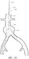
- FIG. 1is a partial section view of a patient's vasculature illustrating an embodiment of an endoluminal prosthesis deployed in the desired position within the patient's vasculature.
- FIG. 2is a side view of the endoluminal prosthesis illustrated in FIG. 1 .
- FIG. 3is a cross-sectional view of the embodiment of the endoluminal prosthesis deployed in the patient's anatomy, taken through line 3 - 3 in FIG. 1 , before the fenestrations have been aligned with the respective branch vessels.
- FIG. 4is a cross-sectional view of the embodiment of the endoluminal prosthesis deployed in the patient's anatomy, taken through line 3 - 3 in FIG. 1 , after the fenestrations have been aligned with the respective branch vessels.
- FIG. 5is a partial section view of a patient's vasculature illustrating another embodiment of an endoluminal prosthesis deployed in the desired position within the patient's vasculature.
- FIGS. 6-12are side views of additional embodiments of endoluminal prostheses.
- FIG. 12Ais an enlarged side view of the embodiment of the endoluminal prosthesis illustrated in FIG. 12 , defined by curve 12 A- 12 A in FIG. 12 .
- FIG. 13is a side view of another embodiment of an endoluminal prosthesis.
- FIG. 14is a top view of the embodiment of the endoluminal prosthesis shown in FIG. 14 .
- FIG. 15is a side view of another embodiment of an endoluminal prosthesis.
- FIG. 16is an enlargement of a portion of the embodiment of an endoluminal prosthesis shown in FIG. 15 , defined by curve 16 - 16 , illustrating the adjustability of a branch graft.
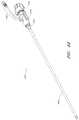
- FIG. 17is a side view of another embodiment of an endoluminal prosthesis with guidewires advanced through each of the branch grafts.
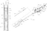
- FIG. 18is a side view of the embodiment of the endoluminal prosthesis shown in FIG. 17 with guidewires advanced through each of the branch grafts, showing the endoluminal prosthesis being loaded within a delivery catheter.
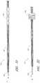
- FIG. 19is a side view of the embodiment of the endoluminal prosthesis shown in FIG. 17 with guidewires advanced through each of the branch grafts, showing the endoluminal prosthesis fully loaded within a delivery catheter and being advanced along guidewires pre-wired in the patient's vasculature.
- FIG. 20is a side view of another embodiment of a delivery catheter that can be used to deploy at least some of the embodiments of the endoluminal prostheses disclosed herein, showing the endoluminal prosthesis being loaded within a delivery catheter.
- FIG. 21is an enlarged side view of a portion of the embodiment of a delivery catheter illustrated in FIG. 20 , showing the endoluminal prosthesis loaded within a delivery catheter.
- FIG. 22Ais a section view of an embodiment of a distal tip that can be used with the embodiment of the delivery catheter that is illustrated in FIG. 20 , taken through line 22 A- 22 A in FIG. 20 .
- FIG. 22Bis a section view of another embodiment of a distal tip that can be used with the embodiment of the delivery catheter that is illustrated in FIG. 20 , taken through line 22 B- 22 B in FIG. 20 .
- FIG. 23Ais a section view of the embodiment of the delivery catheter shown in FIG. 20 , taken through line 23 A- 23 A in FIG. 20 .
- FIG. 23Bis a section view of the embodiment of the delivery catheter shown in FIG. 20 , taken through line 23 B- 23 B in FIG. 20 .
- FIG. 24is a side view of another embodiment of a delivery catheter showing a delivery catheter being advanced distally past a bifurcated graft and showing guidewires being advanced into the renal arteries.
- FIG. 25is a side view of the embodiment of the delivery catheter shown in FIG. 24 , showing biased guidewires being advanced into the renal arteries.
- FIG. 26is a side view of the embodiment of the delivery catheter shown in FIG. 24 , showing the embodiment of the endoluminal prosthesis being deployed within the target vessel region.
- FIG. 27is a side view of the embodiment of the delivery catheter shown in FIG. 24 , showing the endoluminal prosthesis after the distal portion of the endoluminal prosthesis has been deployed within the bifurcated prosthesis.
- FIG. 28is a side view of the embodiment of the delivery catheter shown in FIG. 24 , showing the endoluminal prosthesis after the distal portion of the endoluminal prosthesis has been deployed within the bifurcated prosthesis.
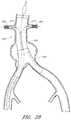
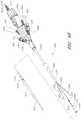
- FIG. 29is a side view of another embodiment of a delivery catheter showing a delivery catheter being advanced distally past renal arteries in the thoracic aorta region of a patient's vasculature.
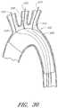
- FIG. 30is a side view of an endoluminal prosthesis that can be deployed using the embodiment of the delivery catheter shown in FIG. 29 .
- FIG. 31is a section view of an embodiment of a guidewire, showing the guidewire in a collapsed configuration.
- FIG. 32is a section view of the embodiment of the guidewire shown in FIG. 31 , showing the guidewire in an expanded configuration.
- FIGS. 33 and 34illustrate a pair of guidewires positioned within the patient's vasculature such that the distal end portions of the guidewires are secured within the patient's branch vessels.
- FIG. 35is a side view of another embodiment of a guidewire, showing the guidewire in an expanded configuration.
- FIG. 36is a side view of another embodiment of a guidewire, showing the guidewire in an expanded configuration.
- FIG. 37is a section view of another embodiment of a guidewire, showing the guidewire in an expanded configuration.
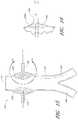
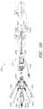
- FIG. 38is a side view of another embodiment of an endoluminal prosthesis, showing the branch grafts in an inverted position inside the main body of the prosthesis.
- FIG. 39is a side view of the embodiment of the prosthesis shown in FIG. 38 , showing the branch grafts in an inverted position inside the prosthesis and showing an embodiment of an angiographic catheter being advanced through each of the inverted branch grafts and the fenestrations.
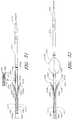
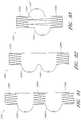
- FIG. 40is a section view of the embodiment of the prosthesis shown in FIG. 40 , taken through line 40 - 40 in FIG. 39 .
- FIG. 41is a section view of the embodiment of the prosthesis shown in FIG. 40 , taken through line 41 - 41 in FIG. 39 .
- FIG. 42is a section view of the embodiment of the prosthesis shown in FIG. 40 , after the branch grafts have been advanced through the fenestrations in the main body of the embodiment of the prosthesis shown in FIG. 38 .
- FIG. 43Ais a side view of another embodiment of a catheter system comprising an embodiment of an introducer catheter and an embodiment of a delivery catheter.
- FIG. 43Bis a perspective view of the embodiment of a catheter system illustrated in FIG. 43A , showing the outer sheath in a partially retracted position.
- FIG. 44is a perspective view of the embodiment of the introducer catheter shown in FIG. 43 .
- FIG. 45is an exploded view of the embodiment of the introducer catheter shown in FIG. 43 .
- FIG. 46is a perspective view of the embodiment of the delivery catheter shown in FIG. 43 .
- FIG. 47is an exploded view of the embodiment of the delivery catheter shown in FIG. 43 .
- FIG. 48is a section view of a portion of the embodiment of the delivery catheter shown in FIG. 43 , defined by curve 48 - 48 shown in FIG. 43A .
- FIG. 49Ais a section view of the embodiment of the delivery catheter shown in FIG. 43 , defined by the line 49 A- 49 A shown in FIG. 48 .
- FIG. 49Bis a section view of the embodiment of the delivery catheter shown in FIG. 43 , defined by the line 49 B- 49 B shown in FIG. 48 .
- FIG. 50is a side view of the embodiment of the catheter system shown in FIG. 43 , showing the outer sheath in a partially retracted position.
- FIG. 51is an enlarged side view of the embodiment of the catheter system shown in FIG. 43 , defined by curve 51 - 51 shown in FIG. 50 , showing the outer sheath in a partially retracted position.
- FIG. 52is an enlarged side view of the embodiment of the catheter system shown in FIG. 43 , defined by curve 52 - 52 shown in FIG. 50 , showing the outer sheath in a partially retracted position and the proximal sheath in a partially advanced position.
- FIG. 53is a side view of the embodiment of the catheter system shown in FIG. 43 , showing the outer sheath in a partially retracted position and the embodiment of one branch sheath and one push catheter in a partially advanced position.
- FIG. 54is a section view of a portion of a patient's vasculature, showing the embodiment of the delivery catheter illustrated in FIG. 43A being advanced through a patient's abdominal aorta.
- FIG. 55is a section view of a portion of a patient's vasculature, showing the embodiment of the delivery catheter illustrated in FIG. 43A and an angiographic catheter being advanced through a branch sheath of the delivery catheter toward a branch vessel.
- FIG. 56is a section view of a portion of a patient's vasculature, showing the embodiment of the delivery catheter illustrated in FIG. 43A and the branch sheaths of the delivery catheter being advanced into a patient's branch arteries.
- FIG. 57is a section view of a portion of a patient's vasculature, showing an embodiment of a distal sheath of the embodiment of the delivery catheter illustrated in FIG. 43A being advanced to deploy a proximal portion of the prosthesis.
- FIG. 58is a section view of a portion of a patient's vasculature, showing an embodiment of a peelable sheath of the embodiment of the delivery catheter illustrated in FIG. 43A being removed to deploy a distal portion of the prosthesis.
- FIG. 59is a section view of a portion of a patient's vasculature, showing an embodiment of a push catheter of the embodiment of the delivery catheter illustrated in FIG. 43A advancing an inner wall of the prosthesis adjacent to a fenestration toward an ostium of the target branch vessel.
- FIG. 60is a section view of a portion of a patient's vasculature, showing an embodiment of a branch stent being advanced into the target branch vessel.
- FIG. 61is a section view of a portion of a patient's vasculature, showing the embodiment of the branch stent of FIG. 60 being expanded in the target branch vessel and flared.
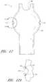
- FIGS. 62A and 62Bare perspective views of an embodiment of a prosthesis having one or more fenestrations therein, the graft being shown in dashed lines in FIG. 62B for clarity.
- FIG. 63is a top view of the embodiment of the prosthesis of FIG. 62 .
- FIG. 64is an enlarged view of a portion of the embodiment of the prosthesis of FIG. 62 , defined by curve 64 - 64 of FIG. 62B .
- FIG. 65is a partially exploded schematic representation of the prosthesis embodiment shown in FIG. 62 .
- FIG. 66is an enlarged side view of the embodiment of the fenestration shown in FIG. 65 , defined by curve 66 - 66 of FIG. 65 .
- FIG. 67is an enlarged section view of the embodiment of the fenestration illustrated in FIG. 65 , showing the end portions of the embodiment of the tubular member being pulled back against the graft.
- FIG. 68is an enlarged section view of the embodiment of the fenestration shown in FIG. 65 , showing the end portions of the embodiment of the tubular member stitched to the graft.
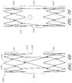
- FIG. 69is a side view of the embodiment of the stent shown in FIG. 62 , perpendicular to an axis projecting through the fenestration.
- FIG. 70is a side view of the embodiment of the stent shown in FIG. 62 , along an axis projecting through the fenestration.
- FIGS. 71-85are side views of additional embodiments of prostheses having or more enlarged portions and one or more fenestrations therein.
- FIG. 86illustrates calculations regarding the theoretical axial adjustability of at least some embodiments of the grafts disclosed herein.
- FIG. 87illustrates calculations regarding the theoretical angular or radial adjustability of at least some embodiments of the grafts disclosed herein.
- Some embodiments described hereinare directed to systems, methods, and apparatuses to treat lesions, aneurysms, or other defects in the aorta, including, but not limited to, the thoracic, ascending, and abdominal aorta, to name a few.
- the systems, methods, and apparatusesmay have application to other vessels or areas of the body, or to other fields, and such additional applications are intended to form a part of this disclosure.
- the systems, methods, and apparatusesmay have application to the treatment of blood vessels in animals.
- the embodiments and/or aspects of the endoluminal prosthesis systems, methods, and apparatuses described hereincan be applied to other parts of the body or may have other applications apart from the treatment of the thoracic, ascending, and abdominal aorta.
- specific embodimentsmay be described herein with regard to particular portions of the aorta, it is to be understood that the embodiments described can be adapted for use in other portions of the aorta or other portions of the body and are not limited to the aortic portions described.
- any of the graft embodiments disclosed hereincan be configured to have excess or slack graft material in at least a portion thereof relative to the stent or support member which supports the graft.
- the excess or slack materialcan result from either an enlarged diametric portion of the graft, excess length of the graft material relative to a stent or other support structure, or a combination of both the enlarged diametric portion of the graft and excess length of the graft material.
- the excess graft materialcan form a bulge or other enlargement in the graft in the approximate location of one or more fenestrations formed through the graft material.
- the excess or slack material along the circumference of the graftcan allow for circumferential and/or axial movement of the graft material and, hence, can allow for circumferential and/or axial movement of the one or more fenestrations, relative to the stent and the ostium of the patient's branch vessels. Therefore, in some embodiments, the diameter of the graft at and/or adjacent to the location of one or more fenestrations through the graft material can be larger than the local diameter of the target vessel. Similarly, in some embodiments, the diameter of the graft at and/or adjacent to the location of one or more fenestrations can be larger than the diameter of the non-enlarged portion of the graft material.
- any of the embodiments disclosed hereincan be configured such that the graft has an enlarged or excess slack portion at or adjacent to the location of the fenestrations, wherein such enlarged or excess slack portion is free of attachment points or has only a minimal number of attachment points to the stent or support structure radially adjacent to the enlarged or excess slack portion.
- thiscan result in both freedom of circumferential and axial movement of the fenestrations, thereby improving the positional adjustability of the fenestrations.
- the enlarged or excess slack portions of the graftcan be radially unsupported by the stent or support member, or can be supported by a stent or support member or by connectors connecting support members positioned axially adjacent to the enlarged or excess slack portion. Accordingly, any of the graft embodiments described herein can be configured to have excess circumferential or longitudinal material at any portion of the graft to increase the positional adjustability of one or more fenestrations formed in the graft.
- any of the graft embodiments disclosed herein, including those with diametrically enlarged portions,can have excess graft material in an axial direction.
- the excess or slack material along the length of the graftcan increase the circumferential and/or axial movement of the graft material adjacent to the one or more fenestrations formed in the graft material.
- the length of the graft material between the proximal and distal attachment points to the stentcan be longer than that of the stent between the proximal and distal attachment points.
- the graft material in a mid portion of the graft, including on either side of the enlarged portioncan have an increased length relative to the stent adjacent to such graft portion.
- the relative position of a patient's left and right renal arteries, a patient's superior mesenteric artery (“SMA”), and a patient's celiac arterycan vary widely.
- the adjustability of one or more fenestrations within the graft materialcan greatly improve the positional ease and accuracy of the fenestrations relative to the patient's branch arteries during deployment of the graft.
- FIG. 1is a partial section view of a patient's vasculature illustrating an embodiment of an endoluminal prosthesis deployed in the desired position within the patient's vasculature.
- the prostheses disclosed hereincan be adapted for deployment in any suitable vessels in the body, some embodiments are described as being deployed in particular vessels or vascular regions within a patient's body. However, the particular prostheses illustrated are not limited to deployment in only one particular vessel or vascular region. In some embodiments, the embodiments shown can be adapted for deployment in other suitable vessels within a patient's body, including the aorta, thoracic artery, renal arteries, iliac arteries, etc.
- FIG. 1an embodiment of an endoluminal prosthesis is shown deployed in a patient's aorta 10 .
- An anuerysmic sac 10 Ais also shown.
- FIG. 2is a side view of the endoluminal prosthesis 20 illustrated in FIG. 1 .
- the embodiment of the endoluminal prosthesis 20 illustrated in FIGS. 1 and 2can have a main graft body 22 , a first fenestration 24 , and a second fenestration 26 .
- the main graftcan be a bifurcated graft having a first bifurcated branch 28 and a second bifurcated branch 30 for placement in the ipsilateral and contralateral iliac arteries.
- the main graft body 22can have a generally cylindrical, tubular shape.
- the endoluminal prosthesis 20can be formed from any suitable material, such as, but not limited to, ePTFE. Some embodiments of the endoluminal prosthesis 20 can be formed from an expandable material.
- the endoluminal prosthesis 20can be formed such that the main graft body 22 can be significantly larger than the target vessel into which the main graft body 22 is to be deployed. As illustrated in FIG. 1 , the target vessel can be the aortic artery, and the endoluminal prosthesis can be deployed so as to span across an aneurysm in the abdominal aortic.
- the diameter of the graft body(such as without limitation the main graft body 22 ) or an enlarged portion of any embodiment of a graft body disclosed herein can be approximately 30% larger than the diameter of the target vessel or the diameter of the non-enlarged portion of the graft body. In some embodiments, the diameter of the graft body (such as without limitation the main graft body 22 ) or an enlarged portion of any embodiment of a graft body disclosed herein can be less than approximately 20%, or from approximately 20% to approximately 50% or more, or from approximately 25% to approximately 40% larger than the target vessel or the diameter of the non-enlarged portion of the graft body, or to or from any values within these ranges.
- At least a portion of the graft material adjacent to the one or more fenestrations or openingscan be free to translate in a circumferential or axial direction relative to the stent that the graft is supported by.
- particular portionssuch as the end portions of the graft material can be sutured or otherwise fastened to the stent, while a mid portion of the graft having one or more fenestrations therethrough can be unattached to the stent so that such mid portion can be free to translate relative to the stent and, hence, permit the adjustability of the fenestrations relative to the stent.
- the fenestrationscan be adjusted to align with the ostium of the patient's branch vessels.
- the diameter of the main graft body 22 configured for placement in an approximately 26 mm vesselcan be approximately 34 mm. Therefore, in some embodiments, the diameter of the main graft body 22 can be approximately 8 mm larger than the diameter of the target vessel. In some embodiments, the diameter of the main graft body 22 can be between approximately 2 mm and approximately 14 mm, or between approximately 4 mm and approximately 12 mm, or between approximately 6 mm and approximately 10 mm larger than the diameter of the target vessel, or to or from any values within these ranges.
- the oversized diameter of the main graft body 22can provide excess or slack graft material in the main graft body 22 such that the fenestrations 24 , 26 can each be moved in an axial or angular direction to align the fenestrations 24 , 26 with the branch vessels arteries, as will be described in greater detail below.
- two or more fenestrationscan be formed in the main graft body 22 at any desired location.
- the two fenestrations 24 , 26can be formed at generally diametrically opposed locations.
- any number of fenestrationscan be formed in the main graft body 22 at any desired locations.
- scallops or cutoutscan be formed in the distal end portion or at any suitable location in the main graft body 22 , the scallops or cutouts being configured to prevent obstruction of other arteries branching off of the main vessel into which the main graft body 22 is to be deployed.
- an additional fenestration 32can be formed in a distal portion of the main graft body 22 .
- the fenestration 32can be formed so as to align with a patient's SMA
- FIG. 3is a cross-sectional view of the embodiment of the endoluminal prosthesis 20 deployed in the patient's anatomy, taken through line 3 - 3 in FIG. 1 , before the fenestrations 24 , 26 have been aligned with the respective branch vessels, for example renal arteries 12 , 14 .
- the main graft body 22(which can be oversized) has been deployed in the target vessel.
- folds 34can form in the main graft body 22 about the circumference of the main graft body 22 .
- the folds 34can form in the main graft body 22 as a result of the fact that there can be excess or slack material in the main graft body 22 after the main graft body 22 has been deployed in the target vessel.
- At least a portion of the main graft body 22can have undulations, folds, bends, corrugations, or other similar features in the axial direction therein when the main graft body 22 is in a relaxed state (i.e., before the graft has been deployed).
- a middle portion of the graftcan have undulations, folds, bends, corrugations or other similar features while the distal or upstream portion defines a smooth contour
- FIG. 4is a cross-sectional view of the embodiment of the endoluminal prosthesis 20 deployed in the patient's anatomy, taken through line 3 - 3 in FIG. 1 , after the fenestrations 24 , 26 have been aligned with the respective branch vessels.
- the oversized main graft body 22can be aligned with the patient's anatomy by moving fenestration 24 to align the fenestration 24 with the respective branch vessel and by moving the fenestration 26 to align the fenestration 26 with the other respective branch vessel.
- the fenestration 24can be drawn closer to the fenestration 26 , thereby gathering slack material or folds 34 in a first portion 22 a of the main graft body 22 and partially or fully removing the slack material or folds from a second portion 22 b of the main graft body 22 .
- a covered stent, a bare wire stent, or any other suitable stent or anchoring devicecan be deployed within the main graft to secure the graft in the desired location (not illustrated).
- a bare metal stent deployed within the main graft body 22can compress the folds 34 that are formed in the main graft body 22 , if any, against the wall of the vessel and secure the main graft body 22 and the fenestrations 24 , 26 in the desired locations.
- a supra renal stentcan be deployed at a distal or upper portion of the main graft body to secure the distal or upper portion of the main graft body in the desired location within the patient's vasculature, and one or more axial springs 40 can be anchored to the main graft body to provide axial or column strength to the main graft body.
- the springs 40can have a helical shape, as illustrated, and can have any suitable size, length, pitch, or diameter. However, such helical shape is not required. In some embodiments, the springs 40 can have any suitable shape, including a straight, flat, round, or non-round shape.
- the springs 40can be formed from any suitable biocompatible material, such as without limitation stainless steel, Nitinol, or suitable metalic or polymeric materials.
- FIG. 5is a partial section view of a patient's vasculature illustrating another embodiment of an endoluminal prosthesis 20 ′ deployed in the desired position within the patient's vasculature wherein the main graft body 22 ′ can have a supra renal stent 38 deployed within the upper or distal end portion of the main graft body 22 ′ and one or more axial springs 40 secured to the main graft body 22 ′.
- the springs 40can be secured to the main graft body 22 ′ using any suitable fasteners or method, such as without limitation, sutures or adhesive.
- any of the embodiments of the endoluminal prostheses disclosed hereincan be formed such that one or more portions of the main graft body have an enlarged diameter, while one or more other portions of the main graft body can have a reduced diameter as compared to the enlarged diameter.
- the endoluminal prosthesis 60can have a main graft body 62 and fenestrations 64 , 66 formed therein.
- an additional fenestration 68can be formed in the main graft body 62 to accommodate blood flow to the SMA or otherwise.
- a first or upper portion 62 a of the main graft body 62can have a first diameter while a second or lower portion 62 b can have a second diameter.
- the first portion 62 acan have a smaller diameter than the second portion 62 b of the main graft body 62 . Accordingly, to accommodate adjustability of the fenestrations 64 , 66 , the fenestrations 64 , 66 can be formed in the second or enlarged portion 62 b of the main graft body 62 .
- the first portion 62 acan have any diameter suitable for the size of the target vessel. Additionally, the second portion 62 b can have an enlarged diameter within any of the ranges described above with respect to the main graft body 22 .
- the endoluminal prosthesis 60can be configured for deployment in a 26 mm target vessel, wherein the first portion 62 a can have an approximately 28 mm or any other suitable diameter, and the second portion 62 b can have an approximately 34 mm or any other suitable enlarged diameter so as to allow for the adjustability of the fenestrations 64 , 66 .
- the diameter of the main graft body 62 in the second portion 62 bcan transition from the diameter of the first portion 62 a to the diameter of the remainder of the second portion 62 b.
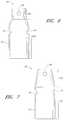
- FIG. 7is a side view of another embodiment of an endoluminal prosthesis 70 having a main graft body 72 and fenestrations 74 , 76 formed therein.
- an additional fenestration or cutout 78can be formed in the main graft body 72 to accommodate blood flow to the SMA or otherwise.
- a first or upper portion 72 a of the main graft body 72can be tapered from a first to a second diameter, while a second or lower portion 72 b can have a second diameter.
- the first portion 72 acan have a smaller diameter than the second portion 72 b of the main graft body 72 . Accordingly, to accommodate adjustability of the fenestrations 74 , 76 , the fenestrations 74 , 76 can be formed in the second or enlarged portion 72 b of the main graft body 72 .
- the first portion 72 acan have any suitable first diameter for the size of the target vessel. Additionally, the second portion 72 b can have an enlarged diameter within any of the ranges described above.
- the endoluminal prosthesis 70can be configured for deployment in a 26 mm target vessel, wherein the first portion 72 a can have an approximately 28 mm first diameter that tapers outwardly to an approximately 34 mm second diameter, and the second portion 72 b can have an approximately 34 mm diameter so as to allow for the adjustability of the fenestrations 74 , 76 .
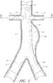
- FIG. 8is a side view of another embodiment of an endoluminal prosthesis 80 having a main graft body 82 and fenestrations 84 , 86 formed therein.
- an additional fenestration 88can be formed in the main graft body 82 to accommodate blood flow to the SMA or otherwise.
- a first or upper portion 82 a of the main graft body 82can have a first diameter
- a second or middle portion 82 bcan have a second diameter
- a third or lower portion 82 ccan have a third diameter.
- the first portion 82 acan have a smaller diameter than the second portion 82 b of the main graft body 82 .
- the third portion 82 ccan have a smaller diameter than the second portion 82 b of the main graft body 82 .
- the third portion 82 ccan have the same diameter as compared to the first portion 82 a . Accordingly, to accommodate adjustability of the fenestrations 84 , 86 , the fenestrations 84 , 86 can be formed in the second or enlarged portion 82 b of the main graft body 82 .
- the second portion 82 bcan have a generally curved surface, or can define a generally cylindrical surface that conically or curvedly tapers to the diameter of the first and third portions 82 a , 82 c.
- the first portion 82 acan have any suitable first diameter for the size of the target vessel. Additionally, as mentioned, the second portion 82 b can have an enlarged diameter within any of the ranges described above.
- the endoluminal prosthesis 80can be configured for deployment in a 26 mm target vessel, wherein the first portion 82 a can have an approximately 28 mm diameter, the second portion 82 b can have an approximately 34 mm diameter so as to allow for the adjustability of the fenestrations 84 , 86 , and the third portion 82 c can have an approximately 28 mm diameter.
- any of the endoluminal prostheses disclosed or described hereincan be bifurcated or non-bifurcated, and can be formed from any suitable material, such as but not limited to ePTFE.
- any of the deployment procedures described herein or any other suitable deployment procedures currently known or later developed that are suitable for such endoluminal prosthesescan be used to deploy any of the endoluminal prostheses described herein.
- any of the endoluminal prosthesescan be secured to the target vessel wall using covered stents, bare metal stents, supra renal stents, springs, anchors, or any other suitable medical device or fasteners.
- covered stentsbare metal stents, supra renal stents, springs, anchors, or any other suitable medical device or fasteners.
- the endoluminal prosthesis 90can be a bifurcated prosthesis.
- the main graft body 92can have three portions 92 a , 92 b , 92 c of varying diameters.
- At least a portion of the graft material adjacent to the one or more fenestrations or openingscan be free to translate in a circumferential or axial direction relative to the stent that the graft is supported by.
- particular portions of the graft materialsuch as the end portions of the graft material, can be sutured or otherwise fastened to the stent, while a mid or enlarged portion of the graft having one or more fenestrations therethrough can be unattached to the stent so that such portion can be free to translate relative to the stent.
- This configurationcan improve the adjustability of the graft material and, hence, the fenestrations, relative to the stent, permitting the fenestrations to be adjusted to align with the ostium of the patient's branch vessels.
- any of the embodiments of the endoluminal prostheses disclosed hereincan be formed with a branch graft adjacent to one or more of the openings or fenestrations formed in the main graft body.
- FIG. 10which is a side view of another embodiment of an endoluminal prosthesis 100
- the endoluminal prosthesis 100can have a main graft body 102 and branch grafts 104 , 106 supported by the main graft body 102 .
- an additional fenestration 108can be formed in the main graft body 102 to accommodate blood flow to the SMA or otherwise.
- an additional branch graft(not illustrated) can be supported by the main graft body 102 to accommodate the blood flow to the SMA
- a first or upper portion 102 a of the main graft body 102can have a first diameter
- a second or middle portion 102 bcan have a second diameter
- a third or lower portion 102 ccan have a third diameter.
- the main graft body 102can have any suitable shape, including any of the shapes disclosed elsewhere herein.
- the first portion 102 acan have a smaller diameter than the second portion 102 b of the main graft body 102 .
- the third portion 102 ccan have a smaller diameter than the second portion 102 b of the main graft body 102 .
- the third portion 102 ccan have the same diameter as compared to the first portion 102 a . Accordingly, to accommodate adjustability of the branch grafts 104 , 106 , the branch grafts 104 , 106 can be supported by the second or enlarged portion 102 b of the main graft body 102 .
- the first portion 102 acan have any suitable first diameter for the size of the target vessel. Additionally, as mentioned, the second portion 102 b can have an enlarged diameter within any of the ranges described above.
- the endoluminal prosthesis 100can be configured for deployment in a 26 mm target vessel, wherein the first portion 102 a can have an approximately 28 mm diameter, the second portion 102 b can have an approximately 34 mm diameter so as to allow for the adjustability of the fenestrations 104 , 106 , and the third portion 102 c can have an approximately 28 mm diameter.
- the branch grafts 104 , 106can be integrally formed with the main graft body 12 .
- the branch graft portions 104 , 106can be formed separately and later attached, adhered, sutured, or otherwise fastened or supported by the main graft body 102 .
- the main graft body 102can have fenestrations or openings in place of the branch grafts 104 , 106 .
- any of the embodiments of the endoluminal prostheses disclosed hereincan be formed with a branch graft adjacent to one or more of the openings or fenestrations formed in the main graft body.
- FIG. 10which is a side view of another embodiment of an endoluminal prosthesis 100
- the endoluminal prosthesis 100In some embodiments, an additional fenestration 108 can be formed in the main graft body 102 to accommodate blood flow to the SMA or otherwise.
- an additional branch graft(not illustrated) can be supported by the main graft body 102 to accommodate the blood flow to the SMA
- a first or upper portion 102 a of the main graft body 102can have a first diameter
- a second or middle portion 102 bcan have a second diameter
- a third or lower portion 102 ccan have a third diameter.
- the main graft body 102can have any suitable shape, including any of the shapes disclosed elsewhere herein.
- the first portion 102 acan have a smaller diameter than the second portion 102 b of the main graft body 102 .
- the third portion 102 ccan have a smaller diameter than the second portion 102 b of the main graft body 102 .
- the third portion 102 ccan have the same diameter as compared to the first portion 102 a . Accordingly, to accommodate adjustability of the branch grafts 104 , 106 , the branch grafts 104 , 106 can be supported by the second or enlarged portion 102 b of the main graft body 102 .
- the first portion 102 acan have any suitable first diameter for the size of the target vessel. Additionally, as mentioned, the second portion 102 b can have an enlarged diameter within any of the ranges described above.
- the endoluminal prosthesis 100can be configured for deployment in a 26 mm target vessel, wherein the first portion 102 a can have an approximately 28 mm diameter, the second portion 102 b can have an approximately 34 mm diameter so as to allow for the adjustability of the fenestrations 104 , 106 , and the third portion 102 c can have an approximately 28 mm diameter.
- the branch grafts 104 , 106can be integrally formed with the main graft body 12 .
- the branch graft portions 104 , 106can be formed separately and later attached, adhered, sutured, or otherwise fastened or supported by the main graft body 102 .
- FIG. 11is a side view of another embodiment of an endoluminal prosthesis 110 .
- any of the features of the endoluminal prosthesis 110can be combined with any of the features of any other embodiment or combination of embodiments of the endoluminal prostheses disclosed herein.
- endoluminal prosthesis 110can have any of the features, components, or other details of any of the other embodiments of the endoluminal prostheses disclosed (directly or by incorporation by reference) herein. As illustrated in FIG.
- the endoluminal prosthesis 110can have a main graft body 112 , fenestrations 114 , 116 formed in the main graft body 112 , and an opening or cutout 118 formed in the distal end portion of the main graft body 112 to accommodate blood flow to the SMA or otherwise.
- branch graftscan be positioned within the fenestrations 114 , 116 , or can be sewn, adhered, or otherwise attached to the main graft body 112 adjacent to the fenestrations 114 , 116 .
- the main graft body 112can have three portions 112 a , 112 b , 112 c of varying diameters.
- the diameter of the three portions 112 a , 112 b , 112 c of the main graft body 112can be approximately the same.
- the first portion 112 acan have any diameter suitable for the size of the target vessel.
- the second portion 112 bcan have an enlarged diameter within any of the ranges described above with respect to the main graft body 22 .
- the endoluminal prosthesis 110can be configured for deployment in a 26 mm target vessel, wherein the first portion 112 a can have an approximately 28 mm or any other suitable diameter, and the second portion 112 b can have an approximately 34 mm or any other suitable enlarged diameter so as to allow for the adjustability of the fenestrations 114 , 116 .
- the diameter of the third portion 112 ccan be similar to the diameter of the first portion 112 a , or can be any suitable diameter.
- the main graft body 112be sized and configured so as to have excess length or material 120 in the graft material.
- the main graft body 112can be sized and configured so as to have excess material 120 below the enlarged second portion 112 b .
- the main graft body 112can be configured so that the excess material 120 is positioned above the enlarged second portion 112 b , or so that excess material 120 is positioned both above and below the enlarged second portion 112 b to allow for greater axial and/or radial adjustability of the fenestrations 114 , 116 .
- the excess material positioned above and/or below the enlarged portion or, if no enlarged portion, above and/or below the fenestrated portion,can permit a greater amount of adjustability of the fenestrations or branch grafts.
- Any of the embodiments of grafts disclosed hereincan have excess material positioned above and/or below the enlarged or fenestrated portion of the graft, or at any suitable position on the graft to increase the adjustability of the fenestrations or branch grafts.
- the excess material 120can be approximately 20% of the unstretched length of the main graft body 112 . In some embodiments, the excess material 120 can be from approximately 10% or less to approximately 30% or more of the unstretched length of the main graft body 112 .
- the total excess length of the graftcan be approximately 2 cm. In some embodiments, the total excess length of the graft can be between approximately 1 cm and approximately 3 cm such that a main graft body 112 having an unstretched length of approximately 10 cm can have from approximately 11 cm or less to approximately 13 cm or more of graft material positioned thereon.
- the endoluminal prosthesis 110can have a supra visceral stent or stent segment 122 deployed within the first or distal end portion 112 a of the main graft body 112 , a stent segment 124 deployed within the third or proximal end portion 112 c of the main graft body 112 , and one or more axial springs 126 extending between the supra renal stent segment 122 and the stent segment 124 .
- the springs 126can be substantially rigid so as to axially position the stent segment 122 at a fixed position relative to the stent segment 124 .
- the springs 126can be attached to the stent segments 124 , 126 at connection points 128 .
- the endoluminal prosthesis 110can be configured such that the main graft body 112 is secured to the stent segments 122 , 124 only at the end portions of the main graft body 112 . In some embodiments, the endoluminal prosthesis 110 can be configured such that the main graft body 112 is secured to the stent segments 122 , 124 at the end portions of the main graft body 112 and also at one or more intermediate positions, such as at positions adjacent to one or more of the connection points 128 .
- the endoluminal prosthesis 110can be configured to be a bifurcated prosthesis, having one or more branch portions extending below the stent 124 .
- the main graft body 112can extend below the stent 124 so as to comprise the branch graft portions.
- bifurcation branch graft portionscan be formed separately and stitched or otherwise attached to the main graft body 112 .
- bifurcation branch stentscan be pre-positioned within or otherwise deployed within the branch grafts.
- FIG. 12is a side view of another embodiment of an endoluminal prosthesis 140 .
- FIG. 12Ais an enlarged side view of the embodiment of the endoluminal prosthesis 140 defined by curve 12 A- 12 A in FIG. 12 .
- any of the features of the endoluminal prosthesis 140can be combined with any of the features of any other embodiment or combination of embodiments of the endoluminal prostheses disclosed (directly or by incorporation by reference) herein.
- endoluminal prosthesis 140can have any of the features, components, or other details of any of the other embodiments of the endoluminal prostheses disclosed herein. As illustrated in FIG.
- the endoluminal prosthesis 140can have a main graft body 142 , fenestrations 144 , 146 formed in the main graft body 142 , and an opening or cutout 148 formed in the distal end portion of the main graft body 142 to accommodate blood flow to the SMA or otherwise.
- branch graftscan be positioned within the fenestrations 144 , 146 , or can be sewn, adhered, or otherwise attached to the main graft body 112 adjacent to the fenestrations 144 , 146 .
- the diameter of the fenestrations 144 , 146 or any other fenestrations disclosed hereincan be from approximately 1 mm to approximately 10 mm or more, or from approximately 3 mm to approximately 8 mm, or from approximately 4 mm to approximately 6 mm.
- the fenestrations 144 , 146can be positioned at any desired or suitable axial or radial position in the main graft body 142 based on a patient's anatomy. In some embodiments, as illustrated in FIG.
- the fenestrations 144 , 146can be circumscribed with a supportive graft material 150 (also referred to herein as a fenestration border) to increase the strength of the graft material adjacent to the fenestrations 144 , 146 .
- the fenestration border 150can increase the strength of the graft material adjacent to the fenestrations 144 , 146 so that the fenestrations 144 , 146 can withstand expansion pressures of up to approximately 15 atm or more.
- the fenestration border 150can be a generally cylindrically shaped tube of graft material such as PTFE, ePTFE, or any other suitable material that is formed around the fenestration.
- the tube of graft materialcan be slit longitudinally along the length thereof and positioned over the edge of the fenestrations 144 , 146 .
- the fenestration border 150can be bonded, sutured, or otherwise attached to or supported by the main graft body 142 adjacent to the fenestrations 144 , 146 .
- the fenestration border 150can be a ring of polyurethane or urethane that can be bonded, sutured, or otherwise attached to or supported by the main graft body 142 adjacent to the fenestrations 144 , 146 .
- the polyurethane or urethanecan allow for radial expansion of the fenestration by a balloon expander or other suitable expander.
- the polyurethane or urethane rings(or rings made from any other suitable material) can be positioned between two or more sheets or layers of graft material (such as, but not limited to, ePTFE) having the polyurethane or urethane bonded thereto.
- the sheets or layerscan be positioned relative to one another with the polyurethane or urethane surfaces facing each other so that the polyurethane or urethane is sandwiched between the sheets or layers of the graft material.
- a radiopaque material(that can be non-rigid or spring-like) can be embedded in or supported within the fenestration border 150 .
- the radiopaque markercan be formed from platinum iridium, which can be in the form of a spring, or any other suitable metallic material known to the industry.
- FIG. 13is a side view of another embodiment of an endoluminal prosthesis 170 .
- FIG. 14is a top view of the embodiment of the endoluminal prosthesis 170 shown in FIG. 13 .
- the embodiment of the endoluminal prosthesis 170 illustrated in FIGS. 13 and 14can have a main graft body 172 , a first fenestration 174 , and a second fenestration 176 .
- the main graft body 172can be bifurcated, having a first bifurcated branch 178 and a second bifurcated branch 180 for placement in the ipsilateral and contralateral iliac arteries and a lumen 182 through the main graft body 172 in communication with the openings in the first and second bifurcated branches 178 , 180 .
- the endoluminal prosthesis 170can have any of the components, features, dimensions, materials, or other details of any of the other embodiments of endoluminal prostheses disclosed or incorporated by reference herein, or any other suitable features of endoluminal prostheses known in the field.
- the endoluminal prosthesis 170can be formed from any suitable material, such as, but not limited to, ePTFE. In some embodiments, the endoluminal prosthesis 170 can be formed from an expandable material. The endoluminal prosthesis 170 can be formed such that at least a portion of the main graft body 172 can be significantly larger than the target vessel into which the main graft body 172 is to be deployed. With reference to FIG. 13 , the endoluminal prosthesis 170 can be bifurcated and can be deployed so as to span across an aneurysm in the abdominal aortic. In some embodiments, at least a portion of the main graft body 172 can have a diameter that can be approximately 30% larger than the diameter of the target vessel. In some embodiments, at least a portion of the main graft body 172 can have a diameter that can be from approximately 20% or less to approximately 50% or more, or from approximately 25% to approximately 40% larger than the target vessel, or to or from any values within these ranges.
- the main graft body 172 configured for placement in an approximately 28 mm vesselcan have at least a portion thereof that has a diameter of approximately 34 mm. Therefore, in some embodiments, the diameter of at least a portion of the main graft body 172 can be approximately 8 mm larger than the diameter of the target vessel. In some embodiments, the diameter of at least a portion of the main graft body 172 can be between approximately 2 mm and approximately 14 mm, or between approximately 4 mm and approximately 12 mm, or between approximately 6 mm and approximately 10 mm larger than the diameter of the target vessel, or to or from any values within these ranges.
- the main graft body 172can have a first portion 172 a , a second or middle portion 172 b , and a third or lower portion 172 c .
- the first portion 172 acan have a generally cylindrical shape defined by a first diameter.
- the second portion 172 bcan have a generally spherical shape defined by a second, enlarged diameter.
- the third portion 172 ccan have a generally cylindrical shape defined by a third diameter. The third diameter can be approximately the same as the first diameter, or can be larger or smaller than the first diameter.
- the second portion 172 bcan have approximately the same cross-sectional diameter as compared to the first portion 172 a , the second portion 172 b having corrugations 184 formed therein, as described below, to allow for the adjustability of the fenestrations 174 , 176 or branch grafts (not illustrated).
- the oversized diameter of the main graft body 172can provide excess or slack graft material in the main graft body 172 such that the fenestrations 174 , 176 can each be moved in an axial or angular direction to align the fenestrations 174 , 176 with the branch vessels arteries.
- branch grafts(not illustrated) can be integrally formed with the main graft body 172 , or can be formed separately and later attached, adhered, sutured, or otherwise fastened or supported by the main graft body 172 .
- two or more fenestrations 174 , 176can be formed in the main graft body 172 at any desired location.
- the two fenestrations 174 , 176can be formed at generally diametrically opposed locations.
- any number of fenestrationscan be formed in the main graft body 172 at any desired locations.
- scallops or cutoutscan be formed in the distal end portion or at any suitable location in the main graft body 172 , the scallops or cutouts being configured to prevent obstruction of other arteries branching off of the main vessel into which the main graft body 172 is to be deployed.
- an additional fenestrationcan be formed in a distal portion of the main graft body 172 so as to align with a patient's SMA.
- the fenestrations 174 , 176can be formed in the second portion 172 b of the main graft body 172 .
- the surface of the second portion 172 b of the main graft body 172can have waves, undulations, folds, corrugations, or other similar features 184 (collectively referred to as corrugations) pre-formed therein.
- the corrugations 184can be formed in an axial direction, as illustrated in FIGS. 13 and 14 , or can be formed in a lateral direction or at any other suitable angular orientation. Additionally, the corrugations 184 can have a linear shape, as illustrated, or can have a curved or any other suitable shape, such as is illustrated in FIGS. 15 and 16 .
- FIG. 15is a side view of another embodiment of an endoluminal prosthesis 190
- FIG. 16is an enlargement of a portion of the embodiment of an endoluminal prosthesis 190 shown in FIG. 15 , defined by curve 16 - 16 , illustrating the adjustability of a branch graft.
- the embodiment of the endoluminal prosthesis 190 illustrated thereincan have a main graft body 192 , a first branch graft 194 , and a second branch graft 196 .
- the main graft body 192can be bifurcated, having a first bifurcated branch 198 and a second bifurcated branch 200 for placement in the ipsilateral and contralateral iliac arteries and a lumen 202 through the main graft body 192 in communication with the openings in the first and second bifurcated branches 198 , 180 .
- the endoluminal prosthesis 190can have any of the components, features, dimensions, materials, or other details of any of the other embodiments of endoluminal prostheses disclosed or incorporated by reference herein, or any other suitable features of endoluminal prostheses known in the field.
- the main graft body 192can be formed without the branch grafts 194 , 196 so that fenestrations are to be aligned with the branch vessels.
- any suitable number of branch grafts or fenestrationscan be formed on the main graft body 192 .
- the corrugations 204 formed in the main graft body 192can be curved.
- the corrugations 204can be generally curved in shape and can be formed about the axial centerline of each of the branch grafts 194 , 196 .
- line L 1represents the axial centerline of each of the branch grafts 194 , 196 when the branch grafts 194 , 196 are in a relaxed state.
- the corrugations 204can define a generally circular shape.
- the corrugations 204can be configured to allow the branch grafts 194 , 196 to move in an axial or angular direction to align the branch grafts 194 , 196 with the branch vessels arteries.
- FIG. 16is an enlargement of a portion of the endoluminal prosthesis 190 shown in FIG. 15 , illustrating the adjustability of a branch graft 196 .
- the branch graft 196can be adjusted from the position defined by line L 1 (which represents the axial centerline of the branch graft 196 in the relaxed state) to the position defined by line L 2 (which represents the axial centerline of the branch graft 196 in the adjusted state).
- Lines L 1 and L 2are meant to describe the adjustment of the branch grafts 194 , 196 in any suitable axial or angular direction and are not meant to be limited by the example or examples provided herein. Further, lines L 1 and L 2 need not be parallel lines, since angular orientation of the branch grafts 194 , 196 relative to the main graft body 192 can be adjustable also.
- the branch grafts 194 , 196can be approximately aligned so that the axial centerline of the branch graft 194 is approximately collinear with the axial centerline of the branch graft 196 .
- the branch grafts 194 , 196can be positioned on the main graft body 192 so that the axial centerline of the branch graft 194 is not aligned or collinear with the axial centerline of the branch graft 196 .
- one or more stentscan be pre-positioned within the branch grafts before the endoluminal prosthesis has been deployed in the target location.
- the one or more stentscan be balloon expandable, self-expandable, or other suitable stents that can be positioned within the branch grafts before the endoluminal prosthesis is loaded into a delivery catheter.
- FIG. 17which is a side view of another embodiment of an endoluminal prosthesis 300
- the endoluminal prosthesis 300can have a main graft body 302 and branch grafts 304 , 306 supported by the main graft body 302 .
- an additional fenestrationcan be formed in the main graft body 302 to accommodate blood flow to the SMA or otherwise.
- a branch graft(not illustrated) can be supported by the main graft body 302 to accommodate the blood flow to the SMA
- the endoluminal prosthesis 300 illustrated in FIG. 17can have any of the same features as compared to the embodiment of the endoluminal prosthesis 100 illustrated in FIG. 10 and described above or any of the embodiments of the endoluminal prostheses disclosed (directly or by incorporation by reference) herein.
- the branch grafts 304 , 306can be supported by the second or enlarged portion 302 b of the main graft body 302 .
- the branch grafts 304 , 306can be integrally formed with the main graft body 302 .
- the branch graft portions 304 , 306can be formed separately and later attached, adhered, sutured, or otherwise fastened or supported by the main graft body 302 .
- first and second guidewires 310 , 312can be advanced through the branch grafts 304 , 306 , respectively.
- the guidewires 310 , 312can be hollow so that they can be passed or advanced over guidewires that are pre-wired in the patient's vasculature to guide the endoluminal prostheses 300 to the target location. Advancing the guidewires 310 , 312 over the pre-wired guidewires can also facilitate the alignment of each of the branch grafts 304 , 306 with each of the branch vessels in the patient's vasculature.
- the guidewires 310 , 312can be made from a plastic extrusion or metal braids.
- the hollow guidewires 310 , 312can be made from braided Nitinol wire.
- the outer diameter of the guidewires 310 , 312can be approximately 0.035 in and the lumen of the guidewire can be approximately 0.016 in to accommodate a second 0.014 in guidewire.
- the guidewires 310 , 312can be configured to pass over a 0.018 in or any other suitable guidewire.
- the guidewires 310 , 312can support balloons on the distal ends of the guidewires 310 , 312 . The balloons can be inflated in the branch vessel to deploy expandable stents within the branch grafts 304 , 306 .
- stents 314 , 316can be positioned within each of the branch grafts 304 , 306 , respectively, before the endoluminal prosthesis 300 is loaded into the delivery catheter.
- each of the stents 314 , 316can be a bare metal stent or a covered stent (i.e., covered with a tubular shaped graft material).
- the stents 314 , 316can be self expanding or can be balloon expandable.
- each of the stents 314 , 316can be supported by an expansion balloon 318 , 320 , respectively, positioned within each of the branch grafts 304 , 306 .
- each of the guidewires 310 , 312can be configured to allow for the inflation and expansion of the expansion balloons 318 , 320 .
- the guidewires 310 , 312can have a first lumen that can be advanced over a pre-wired guidewire and a second inflation lumen configured to communicate a positive pressure to each of the expansion balloons 318 , 320 .
- the endoluminal prostheses 300can be loaded into a delivery catheter so that each of the guidewires 310 , 312 protrudes out from the inside of an outer sleeve of the delivery catheter so that each of the guidewires 310 , 312 can be advanced over the pre-wired guidewires positioned within the patient's vasculature.
- each of the stents 314 , 316can be expanded and hence deployed within each of the branch grafts 304 , 306 after each of the branch grafts 304 , 306 has been aligned and positioned within the respective branch vessels.
- each of the stents 314 , 316can be expanded and hence deployed within each of the branch grafts 304 , 306 before the main graft body 302 has been secured in the main target vessel.
- the stents 314 , 316 and the expansion balloons 318 , 320can be supported within the branch grafts 304 , 306 , respectively, so that the stents 314 , 316 and the expansion balloons 318 , 320 are axially secured to each of the branch grafts 304 , 306 .
- advancing the guidewires 310 , 312 and, accordingly, the stents 314 , 316 and the expansion balloons 318 , 320into the respective branch vessels after the endoluminal prosthesis 300 has been at least partially released from the deployment catheter, can allow the branch grafts 304 , 306 to be aligned with and advanced into the target branch vessels.
- covered or uncovered stentscan be pre-positioned in the main graft body of a fenestrated endoluminal prosthesis so as to be partially advanced through each of the fenestrations before the endoluminal prosthesis is loaded into the delivery catheter.
- the stentscan be secured to or otherwise configured to engage each of the fenestrations such that, as the stents are advanced along the pre-wired guidewires into the respective branch vessels, the fenestrations can be aligned with the respective branch vessels.
- the stentscan have flanged portions or be partially expanded so as to engage the fenestrations such that advancing the stents into the respective branch vessels can align the fenestrations with the respective branch vessels.
- the guidewiresthemselves can be configured to engage each of the fenestrations such that, as the deployment guidewires are advanced along the pre-wired guidewires into the respective branch vessels, the fenestrations can be aligned with the respective branch vessels without the use of stents for alignment.
- one or more stentscan be advanced through the patient's vasculature and into the branch grafts 304 , 306 after the endoluminal prostheses 300 has been positioned within the target vessel in the patient's vasculature.
- one or more stentscan be advanced through the patient's vasculature into the branch grafts 304 , 306 after the branch grafts 304 , 306 have been positioned within the target branch vessels and after the main graft body 302 has been secured within the main target vessel.
- FIG. 18is a side view of the endoluminal prosthesis 300 with guidewires 310 , 312 advanced through each of the branch grafts 304 , 306 , showing the endoluminal prostheses 300 being loaded within a delivery catheter 330 .
- the outer sheath 332 illustrated in FIG. 18is sectioned for clarity.
- the collapsed endoluminal prosthesis 300can be supported within the outer sheath 332 of the delivery catheter 330 in the space between the catheter shaft 334 and the catheter tip 336 .
- the hollow guidewires 310 , 312can slide through openings or lumens in the catheter shaft 86 .
- the hollow guidewires 310 , 312can be fixed to the catheter shaft 334 .
- FIG. 19is a side view of the endoluminal prostheses 300 with guidewires 310 , 312 advanced through each of the branch grafts 304 , 306 , showing the endoluminal prostheses 300 fully loaded within a delivery catheter 330 and being advanced along guidewires pre-wired in the patient's vasculature.
- the outer sheath 332 illustrated in FIG. 19is sectioned for clarity.
- the hollow guidewires 310 , 312can be advanced through the branch grafts 304 , 306 , respectively, of the endoluminal prosthesis 300 .
- the endoluminal prosthesis 300can then be compressed and loaded within the delivery catheter 330 , as is illustrated in FIG. 19 .
- the endoluminal prosthesis 300can be retained in the delivery catheter 330 by the outer sheath 332 . Retraction of the outer sheath 332 can deploy the endoluminal prosthesis 300 . With the outer sheath 332 retracted, the endoluminal prosthesis 300 can expand either by self-expansion, balloon expansion, or by any other suitable method or mechanism.
- the hollow guidewires 310 , 312can pass through the outer sheath 332 from the proximal end of the delivery catheter 330 (i.e., the end of the delivery catheter 330 located outside of the patient) to the distal end of the delivery catheter 330 .
- Each of the hollow guidewires 310 , 312can be configured to receive or allow the insertion of a 0.014 in guidewire, a 0.018 in guidewire, a 0.035 in guidewire, or any diameter guidewire therethrough deemed suitable for the design.
- the hollow guidewires 310 , 312can pass over guidewires 340 , 342 that can be pre-wired in the target vessels.
- the catheter 330can have at least three lumens through at least a portion of the catheter 330 .
- Each of the three lumenscan be configured to receive a guidewire. Having three lumens through at least a portion of the catheter 330 can prevent twisting of the guidewires so as to ensure proper deployment of the endoluminal prostheses 300 or any other endoluminal prostheses disclosed (directly or by incorporation by reference) herein.
- the catheter 330can be configured to receive the pre-wired guidewire 344 through a lumen formed in the approximate center of the catheter. The lumen can pass through the catheter tip 336 and the catheter shaft 334 .
- the guidewires 340 , 342can each be pre-wired through the patient's vasculature to pass into each of the target branch vessels branching from the target main vessel.
- the guidewire 344can be passed through the target main vessel.
- each of the stents 304 , 306can be expanded in the branch vessels to secure the branch grafts 304 , 306 in the branch vessels.
- a stent or other suitable devicecan be deployed within the main graft body 302 to secure the main graft body 302 within the main vessel.
- one or more of the pre-wired guidewires 340 , 342 described abovecan be configured to be insertable into a branch vessel and to be biased such that an end portion of the guidewire 340 , 342 remains in the branch vessel.
- Biasing the end portion of the guidewire 340 , 342 to remain in the branch vesselcan thus improve any of the deployment procedures described herein. Additional details regarding such guidewires is set forth below.
- FIG. 20is a side view of another embodiment of a delivery catheter 400 that can be used to deploy at least some of the embodiments of the endoluminal prostheses disclosed herein, showing an embodiment of an endoluminal prosthesis 402 being loaded within a delivery catheter 400 .
- FIG. 21is an enlarged partial section view of a portion of the embodiment of a delivery catheter 400 illustrated in FIG. 20 , showing the endoluminal prostheses 402 loaded within a delivery catheter 400 . As illustrated in FIGS.
- the endoluminal prosthesis 402can be similar to the endoluminal prosthesis 80 described above, can be a bifurcated endoluminal prosthesis such as endoluminal prosthesis 90 described above, or can have any of the features, components, or other details of any of the other endoluminal prostheses disclosed herein, directly or by incorporation by reference.
- the main graft body 404can be configured to accommodate positional adjustability of the fenestrations 406 , 408 .
- fenestrations 406 , 408can be formed within an enlarged portion of the main graft body 404 .
- the endoluminal prosthesis 302can have a main graft body 404 having fenestrations 406 , 408 formed therein, and one or more stent segments 410 , 412 deployed within the main graft body 404 .
- the stents 410 , 412can be bare metal, covered, self-expandable, balloon expandable, or any other suitable stents either disclosed (directly or by incorporation by reference) herein or otherwise known in the art or later developed. As illustrated in FIGS.
- first and second guidewire sheaths 420 , 422can be advanced through the fenestrations 406 , 408 , respectively, before the endoluminal prosthesis 402 is loaded into a delivery catheter 400 or otherwise such that the first and second guidewire sheaths 420 , 422 are advanced through the fenestrations 406 , 408 , respectively, when the endoluminal prostheses 402 is in the loaded state in the delivery catheter 400 .
- the guidewire sheaths 420 , 422can be hollow so that they can be passed or advanced over pre-positioned guidewires that are pre-wired in the patient's vasculature to guide the endoluminal prostheses 402 to the target location. Advancing the guidewire sheaths 420 , 422 over the pre-wired guidewires can also facilitate the alignment of each of the fenestrations 406 , 408 with each of the branch vessels in the patient's vasculature.
- each of the guidewire sheaths 420 , 422can be made from the same material and have the same features, sizes, or other details of any other guidewire disclosed herein, including without limitation guidewires 310 , 312 described above. Additionally, as with guidewires 310 , 312 , in some embodiments, the guidewire sheaths 420 , 422 can support balloons on the distal ends of the guidewire sheaths 420 , 422 . The balloons can be inflated in the branch vessel to deploy expandable stents within or adjacent to the fenestrations 406 , 408 .
- flared, flareable, bare metal, covered, self-expandable, balloon expandable, or any other suitable stents disclosed (directly or by incorporation by reference) herein, known in the field, or later developedcan be positioned within each of the fenestrations 406 , 408 , respectively, before the endoluminal prosthesis 402 is loaded into the delivery catheter 400 .
- the stentscan be deployed following any suitable procedure, including without limitation the procedure described above with respect to the stents 314 , 316 .
- the branch stents(not illustrated) can be secured to or otherwise configured to engage each of the fenestrations 406 , 408 such that, as the stents are advanced along the pre-wired guidewires into the respective branch vessels, the fenestrations 406 , 408 can be aligned with the respective branch vessels.
- the stentscan have flanged or flared portions or be partially expanded so as to engage the fenestrations 406 , 408 such that advancing the stents into the respective branch vessels can align the fenestrations 406 , 408 with the respective branch vessels.
- the guidewires themselvescan be configured to engage each of the fenestrations 406 , 408 such that, as the deployment guidewire sheaths 420 , 422 are advanced along the pre-wired guidewires into the respective branch vessels, the fenestrations 406 , 408 can be aligned with the respective branch vessels without the use of stents for alignment.
- one or more stentscan be advanced through the patient's vasculature and into the fenestrations 406 , 408 after the endoluminal prostheses 402 has been positioned within the target vessel in the patient's vasculature.
- one or more stentscan be advanced through the patient's vasculature into the fenestrations 406 , 408 after the main graft body 404 has been positioned within the main target vessel or after the fenestrations 406 , 408 have been positioned adjacent to the target branch vessels.
- the delivery catheter 400can have an outer sheath 430 , a distal tip 432 having a lumen or opening 434 therethrough, and a central tube 436 that can secure the distal tip 432 to the delivery catheter 400 .
- the opening 434 in the distal tip 432can extend through the central tube 436 so that the delivery catheter 400 can be advanced over a pre-positioned guidewire.
- the outer sheath 430can be axially moveable relative to the central tube 436 and the distal tip 432 , so that the endoluminal prosthesis 402 can be exposed and deployed from the delivery catheter 400 by retracting the outer sheath 430 relative to the central tube 436 and the distal tip 432 .
- the distal tip 432can be made from a soft material and/or otherwise be configured to be atraumatic to the patient's vasculature so as to minimize injury to the patient's vasculature during advancement of the delivery catheter 400 through the patient's vasculature.
- the distal tip 432can have a substantially circular cross-section along the length thereof, as illustrated in FIG. 22A , which is a section view of an embodiment of a distal tip 432 , taken through line 22 A- 22 A in FIG. 20 .
- the distal tip 432can be tapered along a portion of the length thereof.
- the distal tip 432can have a cross-section that is generally circular, as illustrated in FIG. 22A .
- the distal tip 432 ′can have a non-circular cross-section.
- FIG. 22Bis a section view of another embodiment of a distal tip 432 ′ that can be used with the embodiment of the delivery catheter 400 that is illustrated in FIG. 20 , taken through line 22 B- 22 B in FIG. 20 .
- the distal tip 432 ′can have one or more channels 438 formed along a portion of the length of the distal tip 432 ′.
- the one or more channels 438can each be configured to receive a guidewire sheath 420 , 422 therein.
- the two channels 438can be configured to releasably receive each of the guidewire sheaths 420 , 422 therein so as to reduce the cross-sectional profile of the delivery catheter 400 and to permit the outer sheath 430 to be advanced over the distal tip 432 with the guidewires positioned adjacent to the distal tip 432 and advancing beyond the distal tip 432 without obstruction from the guidewire sheaths 420 , 422 .
- the channels 438can be configured so that the outer sheath 430 can be advanced over and fit closely around the distal tip 432 .
- FIG. 23Ais a section view of the embodiment of the delivery catheter 400 shown in FIG. 20 , taken through line 23 A- 23 A in FIG. 20 .
- FIG. 23Bis a section view of the embodiment of the delivery catheter 400 shown in FIG. 20 , taken through line 23 B- 23 B in FIG. 20 .
- FIGS. 23A and 23Brepresent different embodiments of the delivery catheter 400 .
- some embodiments of the delivery catheter 400can have an outer sheath 430 that can be advanced through an introducer sheath 444 and an inner core 446 that can be axially advanced relative to the outer sheath 430 .
- the delivery catheter 400can be configured so that the inner core 446 can be rotated relative to the outer sheath 430 , or can be configured so that the inner core 446 can be rotationally linked to the outer sheath 430 . Additionally, the inner core 446 can be configured to axially support the central tube 436 and, hence, the distal tip 432 so that, as the inner core 446 is advanced relative to the outer sheath 430 , the central tube 436 and the distal tip 432 can be simultaneously advanced relative to the outer sheath 430 .
- a lumen 450can be formed axially through at least a portion of the inner core 446 , the lumen 450 being configured to slideably receive a guidewire 452 therein.
- the lumen 450can be in communication with the opening 434 that can be formed through the distal tip 432 and the central tube 436 such that the opening 434 and the lumen 450 can slidingly receive a pre-positioned guidewire as the delivery catheter 400 is advanced over the guidewire.
- a lumen 454can be formed through at least a portion of the inner core 446 as illustrated in FIG. 23A , the lumen 454 being configured to slideably receive a guidewire, release wire, or other wire 456 therein.
- the endoluminal prosthesis 402can be similar to or have any of the features of the endoluminal prostheses disclosed in U.S. patent application Ser. No. 12/101,863, filed on Apr. 11, 2008 (entitled “BIFURCATED GRAFT DEPLOYMENT SYSTEMS AND METHODS”), which is hereby incorporated by reference in its entirety as if fully set forth herein.
- the release wire 456can be or can be connected to the sheath release wire 166 used to deploy the main branch sheath 186 in U.S. patent application Ser. No. 12/101,863.
- a lumen 460 having one or more lobescan be formed axially through at least a portion of the inner core 446 .
- the lumen 460can be configured to receive one or more guidewires or guidewire sheaths therein.
- the lumen 460can be configured to receive two guidewire sheaths therein, such as without limitation guidewire sheaths 420 , 422 .
- the guidewire sheaths 420 , 422each can be configured to receive a guidewire catheter therein, such as without limitation guidewire catheters 464 , 466 , respectively, having guidewires 468 , 470 therein.
- the guidewire sheaths 420 , 422can each be sized and configured to axially receive a renal, covered or bare metal stent therein so that a renal stent can be advanced through the guidewire sheaths 420 , 422 and deployed in the renal branch arteries as described herein.
- the renal stents(not illustrated) can be advanced over the guidewire catheters 464 , 466 within the guidewire sheaths 420 , 422 .
- the hollow guidewire sheaths 420 , 422can slide within the lumen 460 .
- the hollow guidewire sheaths 420 , 422can be fixed to the inner core 446 .
- the guidewire catheters 464 , 466can each be configured to receive a pre-positioned guidewire therein, so that the guidewire catheters 464 , 466 can be advanced over pre-positioned guidewires routed into the renal arteries as the delivery catheter 400 is advanced over the pre-positioned guidewire 452 .
- the delivery catheter 400can have an outer sheath 430 that can be advanced through an introducer sheath 444 and an inner core 446 ′ that can be axially advanced relative to the outer sheath 430 .
- the delivery catheter 400can be configured so that the inner core 446 ′ can be rotated relative to the outer sheath 430 , or can be configured so that the inner core 446 ′ can be rotationally linked to the outer sheath 430 .
- the inner core 446 ′can be configured to axially support the central tube 436 and, hence, the distal tip 432 so that, as the inner core 446 ′ is advanced relative to the outer sheath 430 , the central tube 436 and the distal tip 432 can be simultaneously advanced relative to the outer sheath 430 .
- a lumen 450can be formed axially through at least a portion of the inner core 446 ′, the lumen 450 being configured to slideably receive a guidewire 452 therein.
- the lumen 450can be in communication with the opening 434 that can be formed through the distal tip 432 and the central tube 436 such that the opening 434 and the lumen 450 can slidingly receive a pre-positioned guidewire as the delivery catheter 400 is advanced over the guidewire.
- a lumen 454can be formed through at least a portion of the inner core 446 ′ as illustrated in FIG. 23B , the lumen 454 being configured to slideably receive a guidewire, release wire, or other wire 456 therein.
- one or more channels 460 ′can be formed axially on at least a portion of the inner core 446 ′.
- the channels 460 ′can each be configured to receive one or more guidewires or guidewire sheaths therein.
- the channels 460 ′can be configured to receive two guidewire sheaths therein, such as without limitation guidewire sheaths 420 , 422 , configured as described above.
- the guidewire catheters 464 , 466can each be configured to receive a pre-positioned guidewire therein, so that the guidewire catheters 464 , 466 can be advanced over pre-positioned guidewires routed into the renal arteries as the delivery catheter 400 is advanced over the pre-positioned guidewire 452 .
- FIG. 24is a side view of an embodiment of a delivery catheter, such as without limitation delivery catheter 400 described above, showing a delivery catheter 400 being advanced distally past a bifurcated prosthesis 480 and showing guidewire sheaths 420 , 422 being advanced into the renal arteries.
- the delivery catheter 400can then be advanced through the main body of the bifurcated prosthesis 480 into the abdominal aorta and renal artery region.
- the guidewire sheaths 420 , 422can be advanced along pre-positioned guidewires into the renal arteries.
- the outer sheath 430can be partially retracted so that the guidewire sheaths 420 , 422 can be advanced into the renal arteries as the distal tip 432 of the delivery catheter 400 is advanced past the renal arteries along guidewire 452 .
- the pre-placement guidewires (if any) positioned within the guidewire sheaths 420 , 422 and already advanced into the renal arteriescan be removed.
- biased guidewires 482 , 484can be advanced through the guidewire sheaths 420 , 422 and into the renal arteries.
- the coiled distal end portions 482 a , 484 a of each of the biased guidewires 482 , 484can be configured to be insertable into a branch vessel and can be biased to remain in the branch vessel.
- FIG. 26is a side view of the embodiment of the delivery catheter 400 shown in FIG. 24 , showing the embodiment of the endoluminal prosthesis 402 being deployed within the target vessel region.
- the endoluminal prosthesis 402can be a fenestrated cuff.
- the endoluminal prosthesis 402can be deployed by any suitable method, such as without limitation removing a restraining sheath or by any of the methods disclosed in U.S. patent application Ser. No. 12/390,346 or U.S. patent application Ser. No. 12/101,863, each of which are hereby incorporated by reference as if fully set forth herein.
- the endoluminal prosthesis 402can be deployed by removing a perforated sheath using a sheath release wire threaded through perforations in the sheath, such as is set forth in some embodiments of U.S. patent application Ser. No. 12/101,863, which application is fully incorporated herein by reference.
- the proximal end portion of the endoluminal prosthesis 402can be deployed by distally advancing a sheath or other restraint so as to deploy the proximal end of the endoluminal prosthesis 402 (i.e., the end of the endoluminal prosthesis 402 that is furthest advanced into the vasculature or closest to the heart).
- the proximal end of the endoluminal prosthesis 402can be deployed proximal to the desired visceral vessel (such as, without limitation, the SMA) and then axially retracted until the proximal portion of the endoluminal prosthesis 402 is positioned just below the target visceral vessel (e.g., without limitation, the SMA).
- the adjustable fenestrations 406 , 408can then be adjusted to be positioned adjacent to the respective renal arteries.
- FIG. 27is a side view of the embodiment of the delivery catheter 400 shown in FIG. 24 , showing the endoluminal prosthesis 402 after the distal portion of the endoluminal prosthesis 402 has been deployed within the bifurcated prosthesis 480 .
- the inner core 446 , distal tip 432 , and central tube 436can be axially retracted through the outer sheath 430 and removed from the target vessel region, leaving the guidewire sheaths 420 , 422 positioned within the patient's renal arteries.
- the delivery catheter 400 illustrated in FIG. 23Bcan be configured such that the inner core 446 , distal tip 432 , and central tube 436 can be axially retracted through the outer sheath 430 while leaving the guidewire sheaths 420 , 422 positioned within the renal arteries.
- any suitable renal stentscan be advanced through the guidewire sheaths 420 , 422 and deployed within the renal arteries over the biased guidewires 482 , 484 or other guidewires in the renal arteries.
- renal stents(such as without limitation stents 314 , 316 ) can be advanced through the guidewire sheaths 420 , 422 and deployed within the renal arteries over the biased guidewires 482 , 484 or any other guidewires without removing the inner core 446 , distal tip 432 , and central tube 436 .
- FIG. 29is a side view of another embodiment of a delivery catheter 500 showing a delivery catheter 500 being advanced distally past branch arteries in the thoracic aorta region of a patient's vasculature.
- FIG. 30is a side view of an endoluminal prosthesis 502 that can be deployed using the embodiment of the delivery catheter 500 shown in FIG. 29 .
- the endoluminal prosthesis 502can have a main graft body 504 having multiple fenestrations 506 , 508 , 510 formed therein.
- the delivery catheter 500can have an outer sheath 514 and a distal tip 516 configured to be advanced over a guidewire 518 , as with the other embodiments of the delivery catheters disclosed herein.
- the endoluminal prosthesis 502 and delivery catheter 500can have any of the components, features, or other details of any of the other endoluminal prostheses or delivery catheters disclosed (directly or by incorporation by reference) herein.
- the endoluminal prosthesis 502can have stents or stent segments deployed within the main graft body 504 , springs, or other suitable structures deployed or supported within the main graft body 504 .
- the main graft body 504can have an enlarged diameter along at least a portion of the main graft body 504 and/or an additional graft material or length along at least a portion of the main graft body 504 to improve the adjustability of the fenestrations 506 , 508 , 510 .
- the delivery catheter 500 and the endoluminal prosthesis 502can be configured such that a guidewire sheath (such as without limitation guidewire sheaths 420 ) can be pre-positioned within the delivery catheter 500 and the endoluminal prosthesis 502 , the guidewire sheaths (not illustrated in FIGS. 29, 30 ) advancing through each of the fenestrations 506 , 508 , 510 .
- the distal tip 516 of the delivery cathetercan be configured to have channels formed therein configured to receive the guidewire sheaths, similar to the distal tip 432 ′ disclosed herein.
- the branch arteriescan be pre-wired with guidewires 520 , 522 , 524 (which can be biased guidewires), similar to any of the pre-wiring techniques for the renal arteries disclosed herein, so that the delivery catheter 500 and the endoluminal prosthesis 502 having guidewire sheaths positioned therein can be advanced over the guidewires 520 , 522 , 524 to approximately align the fenestrations 506 , 508 , 510 as the endoluminal prosthesis 502 is being advanced into the target vessel region.
- guidewires 520 , 522 , 524which can be biased guidewires
- the guidewire sheathscan be advanced into the branch arteries as the endoluminal prosthesis 502 is being deployed, similar to the deployment of the aortic grafts disclosed herein. Thereafter, any suitable branch stents (such as without limitation stents 314 , 316 ) can be advanced through the guidewire sheaths (not illustrated) and deployed within the branch arteries over the guidewires 520 , 522 , 524 .
- any suitable branch stentssuch as without limitation stents 314 , 316
- stentscan be advanced through the guidewire sheaths (not illustrated) and deployed within the branch arteries over the guidewires 520 , 522 , 524 .
- FIG. 31is a section view of an embodiment of a guidewire 700 , showing the guidewire 700 in the open or collapsed configuration.
- FIG. 32is a section view of the embodiment of the guidewire 700 shown in FIG. 31 , showing the guidewire 700 in the closed or expanded configuration.
- the guidewire 700can be used in place of either of the guidewires 340 , 342 shown in FIG. 19 and described above.
- Any of the guidewires disclosed hereincan comprise a shape memory material, such as without limitation Nitinol.
- the guidewire 700can have an outer guidewire sheath 702 having an expandable portion 704 . Additionally, the guidewire 700 can have an inner guidewire core 706 slidably received within a lumen formed within the outer guidewire sheath 702 . In some embodiments, the outer guidewire sheath 702 can be sized and configured such that the guidewires 310 , 312 described above or any other guidewires or lumens can be advanced over the outside of the outer guidewire sheath 702 , as described above.
- the expandable portion 704can be configured such that, when the expandable portion 704 is axially collapsed, the diameter of the expandable portion 704 can increase and be configured such that, when the expandable portion 704 is axially extended, the diameter of the expandable portion 704 can decrease.
- the expandable portion 704can be axially extended, thus reducing the diameter of the expandable portion 704 .
- FIG. 31illustrates that as the inner guidewire core 706 is advanced relative to the outer guidewire sheath 702 in the direction represented by arrow A 1 in FIG. 31 .
- the collapsible portioncan be axially compressed, thus increasing the diameter of the expandable portion 704 .
- the expandable portion 704can have a bellows type, undulating, or corrugated outer surface.
- the guidewire 700can be advanced through the patient's vasculature to the target branch vessel while the guidewire 700 is in the collapsed configuration (i.e., the configuration shown in FIG. 31 ).
- the inner guidewire core 706can then be retracted relative to the outer guidewire sheath 702 (i.e., retracted in direction A 2 relative to the outer guidewire sheath 702 ) so that the diameter of the expandable portion 704 can be increased and expand radially against the inner surface of the branch vessel wall.
- the expandable portion 704can secure the distal end portion of the guidewire 700 in the desired branch vessel.
- the expandable portion 704can be formed from a soft, atraumatic material to minimize the risk of any injury to the vessel wall.
- FIGS. 33 and 34each illustrate a pair of guidewires 700 positioned within the patient's vasculature such that the distal end portions of the guidewires 700 can be secured at least partially within the patient's branch vessels.
- the guidewires 700can be positioned within the patient's vasculature such that a portion of the expandable portion 704 protrudes into the lumen of the main vessel, which a portion of the expandable portion 704 protrudes into the branch vessel.
- the distal end portion of the guidewires 700have been advanced further as compared to the guidewires 700 shown in FIG. 33 , to allow additional space for the deployment of branch grafts within the branch vessels.
- the expandable portion 704can be formed from metal, plastic, or any other suitable material, and can have an expandable bellows configuration or can be formed from one or more braids of wire. Additionally, in some embodiments, the expandable portion 704 can be used to align the fenestrations or branch grafts with the branch vessels.
- any of the deployment catheters described abovecan then be advanced over the guidewires 700 .
- the guidewire core 706can then be retracted relative to the outer sheath 702 of the guidewires 700 so that the guidewires 700 can be removed from the patient's vasculature.
- other securing mechanismscan be attached to the distal end portion of the guidewire, such as, without limitation, hooks, barbs, or other similar features, to removably secure one or more of the guidewires 700 within the vessel.
- one of more of the guidewires disclosed hereincan have a coiled distal end portion.
- the coiled distal end portioncan be configured to be insertable into a branch vessel and can be biased to remain in the branch vessel.
- the size or diameter of the coilscan be greater than the inside diameter of the branch vessel so as to bias the coiled portion to remain within the branch vessel when the proximal end of the guidewire is retracted.
- proximal retraction of the guidewirecan cause a proximal end of the coil to unravel, allowing a portion of the coiled portion of the guidewire to be unraveled and retracted while the remaining portion of the coiled portion can remain within the branch vessel.
- This configurationcan inhibit the distal end portion of the guidewire from being inadvertently removed from the branch vessel.
- the guidewirecan be retracted until the entire coiled portion is unraveled and retracted.
- the inner guidewire core 706 of the guidewire 700can be configured such that, when the distal end of the inner guidewire core 706 is advanced beyond the distal end of the outer guidewire sheath 702 , the distal end of the inner guidewire core 706 forms coils that expand against the inner vessel wall and secure the guidewire 700 to the branch vessel.
- FIG. 35is a side view of another embodiment of an expandable guidewire 720 , showing the guidewire 720 in an expanded configuration.
- the guidewire 720can have expansion struts 722 that can expand when deployed in the renal or other branch arteries.
- the guidewire 720can be formed from a tube of Nitinol that can be perforated or cut so as to form a plurality of axial members or struts 722 , and heat set so that the expansion struts 722 form a size that is larger than the desired vessel diameter.
- the guidewirecan have four or less, or six, or eight or more struts 722 .
- the guidewire 720can be advanced through a tubular guidewire sheath that terminates in the desired branch vessel location. As the expansion struts 722 exit the distal end of the tubular guidewire sheath, the expansion struts 722 can self-expand against the walls of the target vessel so as to bias the guidewire 720 in the desired location.
- a two-way guidewirei.e., one having sufficient compressive and tensile strength
- the guidewire 722can have a coiled end portion 724 to be more atraumatic.
- FIG. 36is a side view of another embodiment of a guidewire 730 , showing the guidewire 730 in an expanded configuration.
- the guidewire 730can have a coiled expansion portion 732 that can expand when deployed in the renal or other branch arteries.
- the guidewire 730can be formed from a tube of Nitinol that can be formed so as to define a coiled expansion portion, and heat set so that the coiled expansion portion 732 defines a diameter that is larger than the desired vessel diameter.
- the force from the coiled expansion portion 732 expanding against the vessel wallcan provide a frictional force that inhibits the guidewire from being inadvertently removed from the target branch vessel.
- the coiled expansion portion 732can have two or more, or four or more coils.
- the guidewire 730can be advanced through a tubular guidewire sheath that terminates in the desired branch vessel location. As the coiled expansion portion 732 exits the distal end of the tubular guidewire sheath, the coiled expansion portion 732 can self-expand against the walls of the target vessel so as to bias the guidewire 730 in the desired location.
- a two-way guidewirei.e., one having sufficient compressive and tensile strength
- FIG. 37is a section view of another embodiment of a guidewire 740 , showing the guidewire 740 in an expanded configuration.
- the guidewire 740can have a braided or wire expansion portion 742 that can expand when deployed in the renal or other branch arteries.
- the guidewire 740can be formed from a tube of Nitinol that can be formed so as to define a coiled expansion portion, and heat set so that the braided or wire expansion portion 742 defines a diameter that is larger than the desired vessel diameter.
- the expansion portion 742can be formed from between approximately five and ten or more wires each having a diameter between approximately 0.003 in or less and approximately 0.005 in or more.
- the expansion portion 742can be formed from between approximately three and twelve or more wires.
- the force from the expansion portion 742 expanding against the vessel wallcan provide a frictional force that inhibits the guidewire from being inadvertently removed from the target branch vessel.
- the guidewire 740can be advanced through a tubular guidewire sheath that terminates in the desired branch vessel location. As the expansion portion 742 exits the distal end of the tubular guidewire sheath, the expansion portion 742 can self-expand against the walls of the target vessel so as to bias the guidewire 740 in the desired location.
- a two-way guidewirei.e., one having sufficient compressive and tensile strength
- FIG. 38is a side view of another embodiment of an endoluminal prosthesis 745 , showing the branch grafts 750 in an inverted position inside the main body 748 of the prosthesis 745 .
- FIG. 39is a side view of the embodiment of the prosthesis 745 shown in FIG. 38 , showing the branch grafts 750 in an inverted position inside the main body 748 of the prosthesis 745 and showing an embodiment of an angiographic catheter 751 being advanced through each of the inverted branch grafts 750 and the fenestrations 749 .
- Some embodiments of the angiographic catheter 751can be configured such that an end portion thereof is biased to have a curved disposition. In some embodiments, this can be accomplished by shortening the length of the wall of one side of the end portion of the angiographic catheter 751 as compared to the length of the wall of the other side of the angiographic catheter 751 .
- Some embodiments of the endoluminal prosthesis 745can have a main graft body 748 having fenestrations or openings 749 therein and branch grafts 750 supported by the main graft body 748 .
- an additional fenestrationcan be formed in a first portion 748 a of the main graft body 748 to accommodate blood flow to the SMA or otherwise.
- a branch graft(not illustrated) can be supported by the main graft body 748 to accommodate the blood flow to the SMA.
- the endoluminal prosthesis 745 illustrated in FIG. 38can have any of the same features, components, or other details as compared to any of the embodiments of the endoluminal prostheses disclosed (directly or by incorporation by reference) herein, including without limitation the embodiment of the endoluminal prosthesis 100 illustrated in FIG. 10 and described above.
- the branch grafts 750can be supported by the second or enlarged portion 748 b of the main graft body 748 .
- the branch grafts 750can be integrally formed with the main graft body 748 .
- the branch graft portions 750can be formed separately and later attached, adhered, sutured, or otherwise fastened or supported by the main graft body 748 .
- angiographic catheters 751 or hollow guidewirescan be advanced through the branch grafts 750 and fenestrations 749 .
- the angiographic catheters 751can define a lumen therethrough so that they can be passed or advanced over guidewires 752 that are pre-wired in the patient's vasculature to guide the endoluminal prostheses 745 to the target location. Advancing the angiographic catheters 751 over the pre-wired guidewires 752 can also facilitate the alignment of each of the branch grafts 750 with each of the branch vessels in the patient's vasculature.
- the branch grafts 750can be inverted and positioned within the main body 748 of the prosthesis 745 during the initial steps of deployment of the prosthesis 745 .
- the prosthesis 745may be easier to advance to and deploy at the target vessel location when the branch grafts 750 are inverted and positioned within the main body 748 of the prosthesis 745 .
- the prosthesismay be configured such that the branch grafts 750 can be advanced through the fenestrations 749 in the main body 748 of the prosthesis 745 and into the desired branch vessels after the main body 748 of the prosthesis 745 has been positioned in the target vessel location.
- one or more stents 757can be deployed or expanded within the branch grafts 750 after the branch grafts have been advanced into the branch vessels.
- the stents 757or any other stents disclosed (directly or by incorporation by reference) herein, can be balloon expandable, self-expandable, flared, flareable, or be of any other suitable configuration or material, and can be carried or supported within a guidewire catheter sheath 754 .
- the prosthesis 745can be configured such that the stents 757 are affixed to an end portion of the branch grafts 750 such that the branch grafts 750 can be inverted and advanced through the fenestrations 749 formed in the main graft body 748 and into the branch vessels by advancing the stents 757 distally through the guidewire catheter sheath 754 .
- the stents 757can be advanced distally through the guidewire catheter sheath 754 by advancing a pusher catheter 755 that is radially supported but axially unrestrained within the guidewire catheter sheath 754 .
- FIG. 40is a section view of the embodiment of the prosthesis 745 shown in FIG. 38 , taken through line 40 - 40 in FIG. 39 .
- the angiographic catheters 751can be configured to be axially advanceable over the guidewires 752 .
- a pusher catheter 755can be housed within each guidewire catheter sheath 754 so as to be axially advanceable over each angiographic catheter 751 and within the guidewire catheter sheath 754 .
- FIG. 41is a section view of the embodiment of the prosthesis 745 shown in FIG. 40 , taken through line 41 - 41 in FIG. 39 .
- the angiographic catheter 751can be configured to be axially advanceable over a guidewire 752 .
- the stents 757can be housed within the guidewire catheter sheath 754 so as to be axially advanceable over the angiographic catheter 751 and within the guidewire catheter sheath 754 .
- FIG. 42is a section view of the embodiment of the prosthesis 745 shown in FIG. 38 , after the branch grafts 750 have been advanced through the fenestrations 749 in the main body 748 of the embodiment of the prosthesis 745 shown in FIG. 38 .
- the angiographic catheters 751can be made from a plastic extrusion or metal braids.
- the hollow angiographic catheters 751can be made from braided Nitinol wire.
- the outer diameter of the angiographic catheters 751can be approximately 0.035 in and the lumen of the guidewire can be approximately 0.016 in to accommodate a second 0.014 in guidewire.
- the angiographic catheters 751can be configured to pass over a 0.018 in or any other suitable guidewire.
- the outer diameter of the angiographic catheters 751can be approximately 5 Fr and the lumen of the guidewire can be approximately 0.040 in to accommodate a second 0.035 or 0.038 in guidewire.
- the angiographic catheters 751can be configured to pass over a 0.018 in or any other suitable guidewire.
- the angiographic catheters 751can be configured to support balloons on the distal ends of the angiographic catheters 751 . The balloons can be inflated in the branch vessel to deploy expandable stents such as stents 757 within the branch grafts 750 .
- each of the stents 757can be a bare metal stent or a covered stent (i.e., covered with a tubular shaped graft material). Additionally, in some embodiments, the stents 757 can be self expanding or can be balloon expandable. Although not required, each branch graft 750 can be fixed at an end portion thereof to an end portion of each stent 757 . In some embodiments, each of the stents 757 can be supported by or positioned over an expansion balloon positioned within each of the guidewire catheter sheaths 754 . The balloons can be slideable within the guidewire catheter sheaths 754 so that the balloons can be advanced distally simultaneously with the stents 757 .
- the balloonscan be slideable over the angiographic catheters 751 so that the balloons can be advanced over the angiographic catheters 751 as the stents 757 are advanced over the angiographic catheters 751 .
- the balloonscan be expanded to deploy the stents 757 once the stents 757 are positioned in the target location within the branch vessels.
- the angiographic catheters 751can be retracted after the stents 757 are positioned in the target location within the branch vessels. Thereafter, one or more balloons supported by a guidewire catheter, balloon catheter, or other suitable catheter can be advanced over the guidewires 752 and into the branch vessels to expand or otherwise deploy the stents 757 .
- the angiographic catheters 751can be configured to allow for the inflation and expansion of expansion balloons so as to expand or deploy the branch stents 757 .
- the angiographic catheters 751can have a first lumen that can be advanced over a pre-wired guidewire and a second inflation lumen configured to communicate a positive pressure to the expansion balloon or balloons.
- the endoluminal prostheses 745can be loaded into a delivery catheter so that each of the angiographic catheters 751 protrudes out from the inside of the guidewire catheter sheath 754 so that each of the angiographic catheters 751 can be advanced over the pre-wired guidewires 752 positioned within the patient's vasculature.
- each of the stents 757can be expanded and, hence, deployed within each of the branch grafts 750 after each of the branch grafts 750 has been advanced into the respective branch vessels.
- each of the stents 757can be expanded and, hence, deployed within each of the branch grafts 750 before the main graft body 748 has been secured in the main target vessel.
- one or more stentscan be advanced through the patient's vasculature and into the branch grafts 750 after the endoluminal prostheses 745 has been positioned within the target vessel in the patient's vasculature.
- one or more stentscan be advanced through the patient's vasculature into the branch grafts 750 after the branch grafts 750 have been inverted and advanced into the target branch vessels and after the main graft body 748 has been secured within the main target vessel.
- the hollow angiographic catheters 751can pass through a distal end opening of an outer sheath of a deployment catheter, just as with the delivery catheter 330 described above.
- each of the hollow angiographic catheters 751can be configured to receive or allow the insertion of a 0.014 in guidewire, a 0.018 in guidewire, a 0.035 in guidewire, or any diameter guidewire therethrough deemed suitable for the design.
- the outer diameter of the angiographic catheters 751can be approximately 5 Fr and the lumen of the guidewire can be approximately 0.040 in to accommodate a second 0.035 or 0.038 in guidewire.
- the angiographic catheters 751can be configured to pass over a 0.018 in or any other suitable guidewire.
- the hollow angiographic catheters 751can pass over guidewires 752 that can be pre-wired in the target vessels so that the deployment catheter housing the prosthesis 745 can be advanced along the guidewires 752 pre-wired in the patient's vasculature, similar to any of the other embodiments of the deployment catheters disclosed or incorporated by reference herein or any other suitable catheter configurations known in the field.
- the guidewire catheter sheaths 755 and the pusher catheters 755can be advanced through each of the fenestrations 749 in the main body 748 of the prosthesis 745 .
- Advancing the guidewire catheter sheaths 755 and the pusher catheters 755 through each of the fenestrations 749 in the main body 748 of the prosthesis 745can cause each branch graft 750 to be advanced through the fenestrations 749 and to invert and slide over an end portion of each guidewire catheter sheath 755 and slide around an outside surface of each guidewire catheter sheath 755 , so that each branch graft 750 can extend in the appropriate orientation in each of the branch vessels.
- an end portion of the guidewire catheter sheath 755can be positioned within the branch graft 750 after the branch graft 750 has been advanced into the branch vessel as described above. Thereafter, in some embodiments, the pusher catheter 755 can be used to hold the stent 757 in the target location while the guidewire catheter sheath 755 is retracted. If the stent 757 is self-expandable, retracting the guidewire catheter sheath 755 will permit the stent 757 to self-expand radially outwardly, thereby securing the branch graft 750 in the target location.
- the angiographic catheter 751can be used to expand and deploy the stent 757 in the target location.
- Each of the branch grafts 750can be deployed sequentially or simultaneously in this arrangement.
- a stent or other suitable devicecan be deployed within the main graft body 748 to secure the main graft body 748 within the main vessel.
- each branch graft 750can be fixed at an end portion thereof to an end portion of each stent 757 .
- an end portion of the branch graft 750can be affixed to at least a proximal end portion of the respective stent 757 so that the branch graft 250 can substantially completely cover an inside and an outside surface of the stent 757 after the branch graft 750 has been inverted and advanced into the branch vessel.
- one or more of the pre-wired guidewires 752 described abovecan be configured to be insertable into a branch vessel and to be biased such that an end portion of the guidewires 752 remains in the branch vessel, such as with any of the guidewires.
- one or more of the guidewires 752can be configured to have the same features as, without limitation, any of guidewires 700 , 720 , 730 , or 740 disclosed herein.
- FIG. 43Ais a side view of another embodiment of a catheter system 1000 comprising an embodiment of an introducer catheter 1002 (also referred to as an introducer) and an embodiment of a delivery catheter 1004 .
- the delivery catheter 1004can be configured for the delivery of an endoluminal prosthesis, including without limitation any endoluminal prosthesis embodiment disclosed herein or any other suitable prosthesis, or for any other suitable use. Therefore, the embodiments of the catheters and introducers disclosed herein can be configured for any suitable purpose, including deployment of a stent graft system as described herein.
- FIG. 43Bis a perspective view of the embodiment of a catheter system 1000 illustrated in FIG. 43A , showing an outer sheath 1006 of the delivery catheter 1004 in a partially retracted position.
- some embodiments of the outer sheath 1006can be used to constrain at least a portion of a prosthesis 1010 .
- the prosthesis 1010can have any of the same features, components, or other details of any of the other prosthesis embodiments disclosed herein, including without limitation the embodiments of the prosthesis 1200 described below.
- the prosthesis 1010can have any number of stents or other support members, connectors, grafts, cuts, fenestrations, or other suitable components or features.
- a distal sheath 1012(also referred to herein as a first restraint or first restraining means) can be used to constrain a proximal portion of the stent graft 1010 .
- the distal sheath 1012can be supported by a distal tip 1014 of the catheter system 1000 .
- the distal tip 1014can comprise an atraumatic material and design.
- the distal tip 1014 and, hence, the distal sheath 1012can be attached to an inner tube 1016 to control the position of the distal tip 1014 and the distal sheath 1012 relative to an inner core 1020 of the delivery catheter 1004 .
- the inner core 1020can be rotatable relative to the outer sheath 1006 so that a prosthesis supported by the delivery catheter 1004 can be rotated during deployment.
- the inner tube 1016can be slidably positioned coaxially within a lumen in an outer tube 1018 that can connect a support member 1022 to the inner core 1020 .
- the outer tube 1018can be connected to an opening or partial lumen 1019 in the inner core 1020 so as to be axially and rotationally fixed to the inner core 1020 .
- the catheter system 1000can be configured such that advancing the inner tube 1016 relative to an inner core 1020 of the delivery catheter 1004 can cause the distal sheath 1012 to be advanced relative to the prosthesis 1010 , causing the proximal portion of the prosthesis 1010 to be deployed.
- the prosthesis 1010(or any other prosthesis disclosed herein) can be at least partially self-expanding such that, as the tubular distal sheath 1012 is advanced relative to the prosthesis 1010 , a proximal portion of the prosthesis 1010 expands against a vessel wall.
- only some segments or portions of the prosthesis 1010such as, without limitation, portions of the prosthesis axially adjacent to englarged graft portions of the prosthesis, can be configured to be self-expanding.
- the inner core 1020can be slideably received within the outer sheath 1006 of the delivery catheter 1004 .
- the outer sheath 1006 of the delivery catheter 1004can be longer than an introducer sheath 1008 of the introducer catheter 1002 .
- a clip 1007can be supported by the outer sheath 1006 to limit the range of axial movement of the outer sheath 1006 relative to the introducer catheter 1002 .
- a core assembly 1021can be connected to a proximal end portion of the inner core 1020 , the core assembly 1021 having a reduced cross-sectional profile so as to permit one or more sheath members, push catheters, or other tubular or other components to pass through the main body of the delivery catheter 1004 and be advanced into one or more lumen within the inner core 1020 .
- the inner core 1020can be configured to accommodate the insertion of such sheath members, push catheters, or other tubular components into the lumen of the inner core 1020 .
- a proximal end portion of the core assembly 1021can comprise a handle member 1023 that is positioned outside a proximal end portion of the delivery catheter 1004 so as to be accessible by a user.
- the handle member 1023can be configured to permit a user to axially or rotationally adjust the position of the inner core 1020 relative to the outer sheath 1006 .
- the inner core 1020can extend proximally past the proximal end portion 1004 a of the delivery catheter system 1004 so that a user can adjust and/or change the axial and/or radial position of the inner core 1020 and, hence, the prosthesis 1010 , relative to the outer sheath 1006 .
- the inner tube 1016can extend proximally past the proximal end portion 1004 a of the delivery catheter 1004 and a proximal end portion 1021 a of the core assembly 1021 so that a user can adjust and change the position of the inner tube 1016 relative to the inner core 1020 .
- At least a portion of the prosthesis 1010 supported by the catheter system 1000can be exposed and, potentially, deployed.
- a distal portion of the prosthesis 1010can be exposed and deployed by retracting the outer sheath 1006 relative to the inner core 1020 or distally advancing the inner core 1020 relative to the outer sheath 1006 , causing at least a portion of the distal portion of the prosthesis 1010 to self-expand.
- some embodiments of the prosthesis 1010can be configured to have radially self-expanding support members therein along only a portion or portions of the prosthesis 1010 .
- a graft of the prosthesis 1010can be radially unsupported at or adjacent to fenestrations formed in the graft.
- at least the distal portion of the prosthesis 1010can be constrained within a sheath, such as a peelable sheath. Embodiments of the sheath will be described in greater detail below.
- the delivery catheter 1004can also have one or more branch or guide sheaths 1024 supported thereby.
- the delivery catheter 1004can have three or more branch sheaths 1024 .
- Such a configurationcan be used for deploying branch stents into one or more branch vessels in the thoracic aorta.
- Each of the one or more branch sheaths 1024can be configured to be slideably supported within one or more lumen 1025 formed in the inner core 1020 so that each of the one or more branch sheaths 1024 can be axially advanced or retracted relative to the inner core 1020 .
- some embodiments of the delivery catheter 1004can be configured such that the branch sheaths 1024 can be rotationally adjusted or twisted relative to the inner core 1020 .
- each branch sheath 1024can be positioned within the delivery catheter 1004 such that, in the loaded configuration wherein a prosthesis 1010 is supported within the delivery catheter 1004 , each branch sheath 1024 is pre-positioned so as to be advanced through a fenestration or branch graft of the prosthesis 1010 .
- Each branch sheath 1024can be positioned within the delivery catheter 1004 such that a distal end portion of each branch sheath 1024 projects past an end portion of the inner core 1020 and is constrained within the outer sheath 1006 . As illustrated in FIGS. 43A-43B , in this configuration, the distal end portion of each branch sheath 1024 can be exposed by retracting the outer sheath 1006 relative to the inner core 1020 and/or the branch sheaths 1024 .
- the delivery catheter 1004can have one or more push catheters 1026 supported thereby.
- the one or more push catheters 1026can be slideably received within one or more lumen 1027 formed in the inner core 1020 .
- the one or more push catheters 1026can each have an end portion 1026 a that can be sized and configured to surround an outer surface of each of the branch sheaths 1024 .
- each push catheter 1026can have, without limitation, an open or closed annular or circular shape and can be of sufficient size and stiffness to permit a user to engage a fenestration or branch graft formed in or supported by a main body of the prosthesis 1010 .
- a usercan independently or collectively axially advance the push catheter 1026 over the branch sheaths 1024 such that the end portion 1026 a of each push catheter 1026 engages the fenestration or branch graft of the prosthesis 1010 and pushes the fenestration or branch graft toward an ostium of the target branch vessel of the patient's vasculature.
- each push catheter 1026can be positioned within the delivery catheter 1004 such that, in the loaded configuration wherein a prosthesis 1010 is supported within the delivery catheter 1004 , each push catheter 1026 is pre-positioned so that the end portion 1026 a of each push catheter 1026 is positioned distal to the end portion of the inner core 1020 . In some embodiments, in the loaded configuration, each push catheter 1026 can be positioned such that the end portion 1026 a of each push catheter 1026 is located within the main lumen of the main body of the prosthesis 1010 .
- one or more of the branch sheaths 1024can have a loop, protrusion, snare, or other similar feature supported thereby, or otherwise be configured to enable the sheath 1024 to engage a fenestration or branch graft to advance the fenestration or branch graft toward the ostium of the target branch vessel by advancing the branch sheath 1024 .
- the branch sheaths 1024 and push catheters 1026can have any suitable size and can be made from any suitable material.
- the branch sheaths 1024can have an approximately 6.5 French diameter, or from an approximately 5 Fr diameter or less to an approximately 8 Fr diameter or more, or to or from any values within this range.
- the push catheters 1026can be formed from stainless steel, Nitinol, or any other suitable metallic or non-metallic material, and can have a thickness suitable to prevent the push catheters 1026 from buckling when axially advanced against a portion of the prosthesis 1010 .
- the push catheters 1026can have an approximately 1 Fr diameter, or between approximately a 1 Fr and approximately a 4 Fr diameter.
- some embodiments of the push catheter or catheterscan be formed from a 0.035 in guidewire or otherwise have a 0.035 in diameter.
- the catheter system 1000can be configured such that the distal sheath 1012 can be advanced relative to the inner core 1020 and the prosthesis 1010 , to expose a proximal portion of the prosthesis 1010 .
- advancing the distal sheath 1012can be accomplished by advancing the inner tube 1016 connected to the distal tip 1014 and the distal sheath 1012 , so that the distal sheath 1012 releases the proximal portion of the prosthesis 1010 .
- Other details regarding the distal sheath 1012 or methods of using the distal sheathcan be found in U.S. Pat. No. 6,953,475, which application is incorporated by reference as if fully set forth herein.
- FIGS. 44 and 45are a perspective view and an exploded view, respectively, of the embodiment of the introducer catheter 1002 shown in FIG. 43 .
- the introducer catheter 1002can have any of the features or components of any of the embodiments disclosed in U.S. patent application Ser. No. 12/496,446, which disclosure is hereby incorporated by reference as if set forth herein.
- the introducer 1002can have a main body 1030 , a threadably engageable hub portion 1032 , a threaded cap 1034 configured to threadably engage with a threaded distal end portion 1030 a of the main body 1030 so as to secure the outer sheath 1006 to the main body 1030 .
- the outer sheath 1006can have a flanged end portion 1036 secured thereto or integrally formed therewith.
- the main body 1030can support a seal assembly 1040 therein to seal around the inner core 1020 of the delivery catheter 1004 and/or other components of the catheter system 1000 .
- a threaded end member 1042 having a threaded proximal end portion 1042 acan be supported by the main body 1030 .
- An annular seal member 1046can be supported by the main body 1030 of the introducer catheter 1002 .
- the introducer catheter 1002can be configured such that the seal member 1046 can be adjusted to provide an additional seal around the inner core 1020 of the delivery catheter 1004 by threadedly engaging the hub portion 1032 .
- seal assembly 1040 and seal member 1046can have any of the details, features, or components of any of the embodiments of the introducer catheter described in U.S. patent application Ser. No. 12/496,446, which application is incorporated by reference as if fully set forth herein.
- a tube assembly 1048can be supported by the main body 1030 of the introducer catheter 1002 so as to provide an orifice or access port into the main body 1030 .
- the tube assembly 1048can be used to flush the introducer catheter 1002 with saline or other suitable substances at any stage, such as but not limited to prior to the advancement of an endoluminal prosthesis through the introducer catheter 1002 and/or delivery catheter 1004 , or prior to other procedures for which another type of delivery catheter may be used.
- the tube assembly 1048can support any suitable medical connector and/or valve on the distal end thereof.
- FIGS. 46 and 47are a perspective view and an exploded view, respectively of the embodiment of the delivery catheter 1004 shown in FIG. 43 .
- FIG. 48is a section view of a portion of the embodiment of the delivery catheter 1004 shown in FIG. 43 , defined by curve 48 - 48 shown in FIG. 43A .
- FIG. 49Ais a section view of the embodiment of the delivery catheter 1004 shown in FIG. 43 , defined by the line 49 A- 49 A shown in FIG. 48 .
- FIG. 49Bis a section view of the embodiment of the delivery catheter 1004 shown in FIG. 43 , defined by the line 49 B- 49 B shown in FIG. 48 .
- some embodiments of the delivery catheter 1004can have a main body 1050 that can support the inner core 1020 and/or core assembly 1021 , one or more access ports 1052 for the one or more branch sheaths 1024 , and one or more access ports 1054 for the one or more push catheters 1026 .
- the access ports 1052 , 1054can be configured to sealingly tighten around the branch sheaths 1024 or the push catheters 1026 , and to constrict around the branch sheaths 1024 or the push catheters 1026 so as to substantially axially secure the branch sheaths 1024 or the push catheters 1026 .
- a sealable cap assembly 1051can be threadingly engaged with the main body 1050 of the delivery catheter 1004 .
- the cap assembly 1051can be configured such that, when a user tightens the cap assembly 1051 relative to the main body 1050 of the delivery catheter 1004 , the core assembly 1021 and/or inner core 1020 will be axially and/or rotational secured to the main body 1050 of the delivery catheter 1004 .
- a tube assembly 1059can be supported by the main body 1050 of the delivery catheter 1004 so as to provide an orifice or access port into the main body 1050 .
- the tube assembly 1059can be used to flush the delivery catheter 1004 with saline or other suitable substances.
- the tube assembly 1059can support any suitable medical connector and/or valve on the distal end thereof.
- the support member 1022can be connected to a distal end portion of the outer tube 1018 so as to be axially engaged by the outer tube 1018 .
- Some embodiments of the support member 1022can have a substantially cylindrical shape and can be sized to fit within the inner lumen of a main body of the prosthesis 1010 when the prosthesis 1010 is in a constrained configuration.
- the prosthesis 1010in the loaded configuration, can be positioned over the support member 1022 so that a proximal portion of a main body of the prosthesis 1010 is positioned distally of the support member 1022 and so that a distal portion of a main body of the prosthesis 1010 is positioned proximally of the support member 1022 .
- a proximal end portion 1012 a of the distal sheath 1012can be positioned over a distal portion 1022 a of the support member 1022 , and a distal end portion 1006 a of the outer sheath 1006 over a proximal portion 1022 b of the support member 1022 .
- one or more tab members 1074can be supported by the outer tube 1018 .
- the one or more tab members 1074can be configured to increase the rotational engagement of the constrained prosthesis 1010 relative to the outer tube 1018 so that the constrained prosthesis 1010 can be rotated with greater accuracy during deployment.
- Some embodiments of the one or more tab members 1074can have a generally flat, plate-like shape, such as is illustrated in FIG. 46 .
- the one or more tab members 1074can be formed from a suitable polymeric or metallic material.
- Some embodiments of the one or more tab members 1074can comprise one or more radiopaque features or be formed from a radiopaque material to improve the visibility and alignability of the delivery catheter 1004 under fluoroscopy during deployment of the prosthesis 1010 .
- the one or more tab members 1074can be similar to any of the embodiments of the torsion tab (such as without limitation, the embodiment of the torsion tab 196 ) disclosed in U.S. patent application Ser. No. 12/101,863, which disclosure is incorporated by reference as if fully set forth herein.
- the one or more tab members 1074can be integrally formed with the outer tube 1018 , or secured thereto such as by thermal bonding, adhesive bonding, and/or any of a variety of other securing techniques known in the art.
- the main body portion of the prosthesis 1010can be constrained by a peelable sheath or by the outer sheath 1006 such that the prosthesis 1010 is engaged with the one or more tab members 1074 .
- the one or more tabs 1074can engage a stent or other portion of an endoskeleton of the prosthesis 1010 , or, in some embodiments, can engage the material of the graft 1204 surrounding the tab member 1074 so that the prosthesis 1010 can substantially rotate with the inner core 1020 of the deployment catheter 1004 .
- FIG. 50is a side view of the embodiment of the catheter system 1000 shown in FIG. 43 , showing the outer sheath 1006 in a partially retracted position, similar to the configuration shown in FIG. 43B .
- FIG. 51is an enlarged side view of the embodiment of the catheter system shown in FIG. 43 , defined by curve 51 - 51 of FIG. 50 , showing the outer sheath 1006 in a partially retracted position.
- the mid portion of the prosthesis 1010 adjacent to the one or more fenestrations 1011 and/or the distal portion 1010 a of the prosthesiscan be constrained within a peelable sheath 1060 .
- the peelable sheath 1060can have a release wire 1062 threadably advanced through a plurality of openings 1064 formed along at least a portion of the sheath 1060 .
- the peelable sheath 1060 , release wire 1062 , and openings 1064can have any of the same features, materials, or other details of the similar components disclosed in U.S. patent application Ser. No. 12/101,863, which application is incorporated by reference as if fully set forth herein.
- the release wire 1062can be slideably received within a lumen in the inner core 1020 so that a user can retract the release wire 1062 by grasping and retracting a proximal portion of the release wire 1062 positioned outside the patient's body.
- the mid portion of the prosthesis 1010 adjacent to the one or more fenestrations 1011 and/or the distal portion 1010 a of the prosthesiscan be constrained within one or more tubular sheaths, such as the outer sheath 1006 (also referred to herein as a second restraint or second restraining means) and/or distal sheath 1012 such that additional restraining means such as the sheath 1060 are not required. Therefore, any of the embodiments disclosed herein having the optional sheath 1060 should be understood to be configurable to not use the sheath 1060 to restrain one or more portions of the prosthesis 1010 .
- the prosthesis 1010can be configured such that the mid portion of the prosthesis 1010 adjacent to the one or more fenestrations 1011 is not radially supported by a stent, connectors, struts, or any other similar structure such that, when the outer sheath 1006 is partially retracted, the mid portion of the prosthesis does not self-expand.
- the prosthesis 1010can have one or more openings 1011 formed therein.
- the fenestrations or openings 1011can be formed in the prosthesis 1010 at diametrically opposing positions.
- one or more of the openings 1011can be formed in the prosthesis 1010 at a position that is angularly offset from the diametrically opposing position.
- the sheath 1060can have one or more openings 1061 formed therein, the openings 1061 being positioned adjacent to the similar number of openings 1011 formed in the prosthesis.
- Some embodiments of the catheter system 1000can be configured such that the sheaths 1024 are advanced through the openings 1011 formed in the prosthesis 1010 and the openings 1061 formed in the sheath 1060 , when the prosthesis 1010 is loaded within the catheter system 1000 .
- the prosthesis 1010can be efficiently packed within the outer sheath 1006 so as to surround the sheaths 1024 and efficiently fill the space within the outer sheath 1006 .
- the prosthesis 1010can be loaded within the outer sheath 1006 so that the sheaths 1024 are advanced between many of the struts, bends, loops, and other features that the stent can comprise, thereby permitting the sheaths 1024 sufficient space to be loaded within the outer sheath 1006 so that the lumen of the sheaths 1024 are not compressed or collapsed in the loaded state.
- the graftcan be formed from a bi-directionally expanded, layered PTFE material have thin walls to further increase the space efficiency of the prosthesis 1010 .
- the peelable sheath 1060can have one or more release wires 1062 (two being shown) advanced through openings or perforations 1064 formed in the sheath 1060 along two sides of the sheath 1060 .
- the release wires 1062can be configured to tear the sheath 1060 along two lines of perforations 1064 and/or scores formed along two sides of the sheath 1060 , so that the sheath 1060 can be removed from the prosthesis 1010 while the sheaths 1024 are advanced through the fenestrations 1011 , 1061 , respectively, in the prosthesis 1010 and sheath 1060 .
- each of the two release wires 1062can be secured to a proximal end portion 1060 a of the sheath 1060 , so that both halves of the sheath 1060 can be retracted through the outer sheath 1006 .
- FIG. 52is an enlarged side view of the embodiment of the catheter system 1000 shown in FIG. 43 , defined by curve 52 - 52 shown in FIG. 50 , showing the outer sheath 1006 in a partially retracted position and the distal sheath 1012 in a partially advanced position.
- the perforations 1064 formed in the sheath 1060can be arranged along an axial line along the length of the portion of the sheath 1060 from the fenestrations 1061 to the distal end of the sheath 1060 , and also arranged to split the sheath 1060 between the two fenestrations 1061 formed in the sheath 1060 . In some embodiments, as illustrated in FIG.
- the perforations 1064 formed in the sheath 1060 arranged along the length of the sheath 1060can be positioned to tear the sheath 1060 from one of the fenestrations 1061 to the distal end 1060 b of the sheath 1060 , and also to circumferentially tear the sheath 1060 between the fenestrations 1061 .
- some embodiments of the catheter system 1000can be configured such that a proximal portion 1010 b of the prosthesis 1010 can be deployed by axially advancing the inner tube 1016 relative to the inner core 1020 of the delivery catheter 1004 and, hence, the prosthesis 1010 .
- Some embodiments of the prosthesis 1010can be self-expanding such that removing the radial constraint provided by the distal sheath 1012 can cause the portion of the prosthesis 1010 constrained by the inner tube 1016 to expand toward the vessel wall.
- the proximal portion 1010 b of the prosthesis 1010can be deployed in this manner before the distal portion 1010 a of the prosthesis 1010 is deployed, or simultaneously with the deployment of the distal portion 1010 a of the prosthesis 1010 . In some embodiments, the proximal portion 1010 b of the prosthesis 1010 can be deployed in this manner after the distal portion 1010 a of the prosthesis 1010 is deployed.
- FIG. 53is a side view of the embodiment of the catheter system 1000 shown in FIG. 43 , showing the outer sheath 1006 in a partially retracted position and the embodiment of one branch sheath 1024 ′ and one push catheter 1026 ′ in a partially advanced position.
- the branch sheath 1024 ′can be advanced relative to the inner core 1020 , the prosthesis, and the second branch sheath 1024 ′′ by advancing a proximal portion of the branch sheath 1024 ′ in the direction of arrow A 1 in FIG. 53 through the access port 1052 ′ at the proximal end of the delivery catheter 1004 .
- the second branch sheath 1024 ′′can be advanced relative to the inner core 1020 , the prosthesis, and the first branch sheath 1024 ′ by advancing a proximal portion of the branch sheath 1024 ′′ through the access port 1052 ′′ at the proximal end of the delivery catheter 1004 .
- either of the push catheters 1026 ′, 1026 ′′can be advanced relative to the branch sheaths 1024 ′, 1024 ′′ by advancing the respective push catheter 1026 through the respective access port 1054 .
- the push catheter 1026 ′can be advanced by advancing the proximal portion of the push catheter 1026 ′ in the direction of arrow A 2 in FIG. 53 .
- FIG. 54is a section view of a portion of a patient's vasculature, showing the delivery catheter 1000 being advanced through a patient's abdominal aorta over a guidewire 1070 positioned within a patient's vasculature.
- the delivery catheter 1000can be advanced through a prosthesis 1080 (which can be a bifurcated prosthesis) deployed within the patient's vasculature.
- FIG. 55is a section view of a portion of a patient's vasculature, showing the delivery catheter 1000 and an angiographic catheter 1065 being advanced through a branch sheath 1024 of the delivery catheter toward a target branch vessel.
- an outer sheath 1006 of the catheter system 1000has been retracted relative to the inner core (not shown) and the prosthesis 1010 , exposing a middle portion of the prosthesis 1010 (i.e., a portion of the prosthesis 1010 radially adjacent to the one or more fenestrations 1011 ) and the branch sheaths 1024 a , 1024 b .
- a suitable angiographic catheter 1065can be advanced through the lumen of either or both of the branch sheaths 1024 a , 1024 b and directed into the target branch vessel or vessels.
- a usercan rotate the inner core 1020 to approximately rotationally align the fenestrations 1011 of the prosthesis 1010 or the branch sheaths 1024 with the branch vessels.
- the optional sheath 1060can constrain the mid and distal portions of the prosthesis 1010 such that, when the outer sheath 1006 is retracted, the mid and distal portions of the prosthesis 1010 do not self-expand.
- the mid portion of the prosthesis 1010 radially adjacent to the one or more fenestrations 1011can be unsupported by any stents, struts, connectors or can be minimally supported by stents or connectors 1254 (also referred to herein as connecting members).
- the prosthesis 1010can be configured such that there is no radial force or support provided to the mid portion of the prosthesis 1010 , or such that the mid portion of the prosthesis 1010 will not be biased to self-expand when the outer sheath 1006 is retracted. Accordingly, some embodiments can be configured such that no additional restraint in addition to, for example, the outer sheath 1006 , is required. Therefore, in some embodiments, only the outer sheath 1006 and the distal sheath 1012 can be used to restrain the prosthesis 1010 .
- the outer sheath 1006can be partially retracted to release the sheaths 1024 so that one or more angiographic catheters 1065 can be advanced through the sheaths 1024 and into the target branch vessels before the proximal and distal portions of the prosthesis 1010 are released from the deployment catheter 1004 .
- the angiographic catheter 1065can be configured such that an end portion thereof is biased to have a curved disposition. In some embodiments, this can be accomplished by shortening the length of the wall of one side of the end portion of the angiographic catheter 1065 as compared to the length of the wall of the other side of the angiographic catheter 162 . In some embodiments, an end portion of the sheaths 1024 can be also be formed so as to be biased to have a curved end portion. Some embodiments of the sheaths 1024 can be formed in this configuration by heat setting an end portion of the sheath in a curved disposition, or by otherwise shortening the wall of one side of the end portion of the catheter as compared to the other side of the end portion of the catheter. In some embodiments, the branch sheaths 1024 can have a curved end portion so that such sheaths 1024 can be directed into the branch arteries or vessels without the use of an angiographic catheter.
- an angiographic catheter 1065is being advanced relative to the branch sheath 1024 a and into the target branch vessel, in this case a renal artery.
- Some embodiments of the delivery catheter 1000can be configured such that an angiographic catheter can be advanced through the desired branch sheath 1024 and into the target vessel without retracting the outer sheath 1006 .
- the branch sheaths 1024can be independently or simultaneously advanced over the angiographic catheters 1065 into the target branch vessels, as is illustrated in FIG. 56 .
- the branch sheaths 1024 , the fenestrations 1011 , 1061 formed in either the prosthesis 1010 or the sheath 1060 , respectively, and/or any other components or features of the delivery catheter 1000can have radiopaque markers or other indicators to assist a medical practitioner in the deployment procedures described herein or other suitable deployment procedures.
- a proximal portion 1010 b of the prosthesis 1010can be deployed by axially advancing the distal sheath 1012 relative to the inner core 1020 and the prosthesis 1010 .
- the prosthesis 1010can be axially and rotationally secured to the outer tube 1018 , which can be axially and rotationally secured to the inner core 1020 , such that advancing the distal sheath 1012 relative to the inner core 1020 will advance the distal sheath 1012 relative to the prosthesis 1010 .
- the distal sheath 1012can be advanced relative to the inner core 1020 and the prosthesis 1010 by advancing the inner tube 1016 relative to the inner core 1020 , the inner tube 1016 being axially engaged with the distal tip 1014 which can support the distal sheath 1012 .
- FIG. 58is a section view of a portion of a patient's vasculature, showing an embodiment of a peelable sheath 1060 being removed from the distal portion 1010 a of the prosthesis 1010 so as to deploy a distal portion 1010 a of the prosthesis 1010 .
- Some embodiments of the sheath 1060can be removed by axially retracting a release wire 1062 , which can be looped or other otherwise threaded through openings or perforations 1064 formed in the sheath material.
- the release wire 1062can be configured to tear through the sheath material between the perforations 1064 , thereby permitting the self-expanding prosthesis 1010 to expand toward the vessel walls.
- some embodiments of the prosthesis 1010can be configured to be restrained within the outer sheath 1006 and the distal sheath 1012 such that an additional restraint, such as the peelable sheath 1060 , is not required.
- a distal portion 1060 a of the sheath 1060can be torn by the release wire 1062 before a proximal portion 1060 b of the sheath 1060 is torn by the release wire so that a proximal portion 1010 a of the prosthesis (i.e., adjacent to the proximal portion 1060 a of the sheath 1060 ) can be deployed before a distal portion 1010 b of the sheath 1010 .
- a proximal portion 1060 b or a middle portion of the sheath 1060can be torn by the release wire 1062 before a distal portion 1060 a of the sheath 1060 is torn by the release wire.
- the release wire 1062can be secured to the proximal portion 1060 b or other suitable portion of the sheath 1060 such that, after the sheath 1060 has been torn, the sheath 1060 can be removed through the delivery catheter 1000 by continuing to axially retract the release wire 1062 relative to the prosthesis 1010 .
- a distal portion 1010 b of the prosthesis 1010(i.e., the downstream portion of the prosthesis 1010 ) can be deployed within an opening of an adjacent prosthesis, such as without limitation the bifurcated prosthesis 1080 illustrated in FIG. 58 .
- the delivery catheter 1000 or any other delivery catheter described hereincan be used to deploy any suitable prosthesis, including a bifurcated prosthesis or otherwise, in any portion of a patient's vasculature.
- the prosthesis 1000can be a bifurcated prosthesis.
- FIG. 59is a section view of a portion of a patient's vasculature, showing an embodiment of a push catheter 1026 advancing an inner wall of the prosthesis 1010 adjacent to a fenestration 1011 toward an ostium of the target branch vessel.
- the push catheter 1026can be advanced through a lumen in the inner core 1020 to push the fenestration 1011 of the prosthesis 1010 over the branch sheath 1024 and into approximate alignment with the ostium of the branch vessel.
- the catheter system 1000can be configured to not have a push catheter 1026 , and can accordingly be configured to deploy a fenestrated graft without the use of such a component.
- snares, protrusions, tabs, or other featurescan be formed on the sheaths 1024 to push the fenestrations toward the branch vessel ostium.
- a covered or uncovered branch stent 1084can be deployed in the branch vessel by advancing the branch stent 1084 through the branch sheath 1024 using a suitable catheter, such as a renal stent catheter, into the target vessel, after the angiographic catheter has been removed from the branch sheath 1024 .
- the stent 1084can be supported on an inflation balloon 1086 , which can be supported by a guidewire 1088 .
- the guidewire 1088can be configured to have an inflation lumen therein, to inflate the balloon 1086 and expand the branch stent 1084 in the target location after the branch sheath 1024 has been at least partially retracted so as to not interfere with the expansion of the branch stent 1084 , as illustrated in FIG. 61 .
- the inflation balloon 1086can be configured to expand and flare a portion of the stent 1084 within or to the inside of the fenestration 1011 formed in the prosthesis.
- the push catheter 1026 described abovecan be configured to be supported within a renal or branch stent delivery catheter.
- the push catheter 1026can be configured to be supported within a modified embodiment of a renal stent catheter, such as the renal stent catheter illustrated in FIG. 60 .
- the push catheter 1026can be configured to only partially surround the branch sheath 1024 or the branch stent delivery catheter.
- the push catheter 1026can be configured to be entirely positioned within and advanceable through a lumen of the branch sheath 1024 or the branch stent delivery catheter.
- the push catheter 1026can have an expandable end portion that can automatically expand when the end portion is advanced past the end of the lumen, so as to enable the end portion to snare or engage the graft material surrounding the fenestration.
- the branch stent delivery cathetercan be configured to have a snare, protrusion, or other object tethered to the balloon or stent, or to be projecting from an outside surface thereof to snare or engage the graft material adjacent to the fenestration, so as to cause the fenestration to be advanced toward the ostium as the branch stent delivery catheter is advanced through the fenestrations.
- the branch stent delivery cathetercan have a biased wire member supported on an outside surface of the branch stent delivery catheter that is biased to expand when the wire member is advanced past the end of the branch sheath 1024 .
- the wire membercan expand to a size that is larger than the size of the fenestration.
- the wire membercan be supported at a position that is offset from an end of the branch stent delivery catheter.
- the fenestration 1011 in the prosthesis 1010can be expanded as the branch stent 1084 is being expanded, to improve the seal between the fenestration 1011 and the branch stent 1084 .
- a second expansion ballooncan be positioned in the portion of the stent 1084 within or to the inside of the fenestration 1011 to flare that portion of the stent 1084 , either with or without removing the first balloon used to expand the main portion of the branch stent 1084 .
- Some arrangementsare directed to methods of deploying an endoluminal prosthesis, such as without limitation the prosthesis 1010 described above, comprising inserting a delivery catheter such as catheter system 1000 into an artery, exposing one or more branch sheaths 1024 , advancing one or more angiographic catheters with one or more guidewires into the one or more branch sheaths 1024 and cannulating the target branch vessels, advancing the one or more branch sheaths 1024 over the angiographic catheters and into the target branch vessels, deploying a proximal portion of the prosthesis, deploying a distal portion of the prosthesis, removing the one or more angiographic catheters and/or the guidewires, inserting one or more branch stents into the branch vessels, retracting the branch sheaths, expanding the branch stents, and flaring a portion of the branch stents.
- the steps of the foregoing procedurecan be performed in the sequence described, or can be performed in any suitable sequence.
- the target branch vesselsare the renal arteries.
- the step of deploying a distal portion of the prosthesiscan be performed in some arrangements by tearing and retracting a peelable sheath member, or by retracting a tubular sheath such as an outer sheath. Deploying a proximal portion of the prosthesis can be performed in some arrangements by distally advancing a tubular sheath.
- Some arrangementsare directed to methods of deploying an endoluminal prosthesis, such as without limitation the prosthesis 1010 described above, comprising inserting a delivery catheter such as catheter system 1000 into an artery, exposing one or more branch sheaths 1024 , advancing one or more angiographic catheters having one or more guidewires into the one or more branch sheaths 1024 and cannulating the target branch vessels, advancing the one or more branch sheaths 1024 over the angiographic catheters and into the target branch vessels, removing the one or more angiographic catheters and/or guidewires, inserting one or more branch stents into the branch vessels, retracting the branch sheaths, expanding the branch stents, and flaring a portion of the branch stents.
- the target branch vesselscan be the renal arteries.
- Some arrangementsare directed to methods of deploying an endoluminal prosthesis, such as without limitation the prosthesis 1010 described above, comprising inserting a delivery catheter such as catheter system 1000 into an artery, exposing one or more branch sheaths 1024 , advancing one or more angiographic catheters having one or more guidewires into the one or more branch sheaths 1024 and cannulating the target branch vessels, advancing the one or more branch sheaths 1024 over the angiographic catheters and into the target branch vessels, deploying a prosthesis, removing the one or more angiographic catheters and/or guidewires, inserting one or more branch stents into the branch vessels, retracting the branch sheaths, expanding the branch stents, and flaring a portion of the branch stents.
- the target branch vesselsare the renal arteries.
- Some arrangementsare directed to methods of deploying an endoluminal prosthesis, such as without limitation the prosthesis 1010 described above, comprising inserting a delivery catheter such as catheter system 1000 into an artery, exposing one or more branch sheaths 1024 , advancing one or more angiographic catheters having one or more guidewires into the one or more branch sheaths 1024 and cannulating the target branch vessels, advancing the one or more branch sheaths 1024 over the angiographic catheters and into the target branch vessels, advancing the wall of the prosthesis adjacent to each of one or more fenestrations in the prosthesis toward the ostium of the target branch vessels, removing the one or more angiographic catheters and/or guidewires, inserting one or more branch stents into the branch vessels, retracting the branch sheaths, expanding the branch stents, and flaring a portion of the branch stents.
- the target branch vesselsare the renal arteries.
- Some arrangementsare directed to methods of deploying an endoluminal prosthesis, such as without limitation the prosthesis 1010 described above, comprising inserting a delivery catheter such as catheter system 1000 into an artery, exposing one or more branch sheaths 1024 , advancing one or more angiographic catheters having one or more guidewires into the one or more branch sheaths 1024 and cannulating the target branch vessels, advancing the one or more branch sheaths 1024 over the angiographic catheters and into the target branch vessels, deploying a proximal portion of the prosthesis, advancing the wall of the prosthesis adjacent to each of one or more fenestrations in the prosthesis toward the ostium of the target branch vessels, removing the one or more angiographic catheters and/or guidewires, inserting one or more branch stents into the branch vessels, retracting the branch sheaths, expanding the branch stents, and flaring a portion of the branch stents.
- the target branch vesselsare the renal
- Some arrangementsare directed to methods of deploying an endoluminal prosthesis, such as without limitation the prosthesis 1010 described above, comprising advancing a delivery catheter such as catheter system 1000 into a blood vessel or artery, exposing one or more branch sheaths 1024 , advancing one or more angiographic catheters into the one or more branch sheaths 1024 and cannulating the target branch vessels, and advancing the one or more branch sheaths 1024 over the angiographic catheters and into the target branch vessels.
- the steps of the foregoing procedurecan be performed in the sequence described, or can be performed in any suitable sequence.
- the step of advancing the one or more angiographic catheters into the one or more branch sheaths 1024 and cannulating the target branch vesselscan be completed before expanding a main body portion of the prosthesis.
- the one or more angiographic catheterscan have one or more guidewires therein.
- Some arrangementsare directed to methods of deploying a stent graft across at least one branch vessel, the stent graft having at least one lateral opening or fenestration formed therein and the stent graft being constrained within a delivery system having a distal and a proximal end, wherein a catheter extends from the proximal end of the delivery system through the fenestration formed in the stent graft.
- a guidewirecan be passed from the proximal end of the delivery system through the catheter and into the target branch vessel with the proximal and distal end of the stent graft remaining constrained in the delivery system.
- Some embodimentsare directed to apparatuses for placing a prosthesis across at least one branch vessel, the prosthesis having a distal end, a proximal end, a midsection, and at least one lateral opening in the midsection of the prosthesis.
- the prosthesiscan be constrained in a delivery system having a distal and a proximal end.
- the apparatuscan comprise a catheter extending from the proximal end of the delivery system through the lateral opening in the prosthesis, wherein a guidewire can be passed from the proximal end of the delivery system through the catheter, into the branch vessel with at least the proximal and distal ends of the prosthesis remaining constrained in the delivery system.
- the prosthesiscan be a stent graft.
- FIGS. 62A and 62Bare perspective views of an embodiment of a prosthesis 1200 comprising one or more fenestrations 1202 formed in the graft 1204 , and a stent or support member 1206 .
- the embodiment of the graft 1204is shown in dashed lines in FIG. 62B for clarity.
- the prosthesis 1200can have any of the features, components, or other details of any other prosthesis embodiments disclosed herein such as, without limitation, prosthesis 1010 described above. Further, any of the features of the embodiment of the prosthesis 1200 can be used in combination with any of the other prosthesis embodiments disclosed herein.
- the graft 1204can be supported by the stent 1206 along at least a portion of the graft 1204 . Further, the graft 1204 can be overlapped and can have stitching or sutures 1208 along one or more edges of the graft 1204 , which can improve the tear resistance of the graft 1204 and can improve the connection between the graft 1204 and the stent 1206 .
- some embodiments of the graft 1204can be configured to have excess or slack graft material in at least a portion thereof relative to the stent which supports the graft.
- the excess graft materialcan form a bulge or other enlargement in the graft 1204 in the approximate location of one or more fenestrations 1202 formed through the graft material.
- the excess or slack material along the circumference of the graft 1204(for example, without limitation, in the enlarged portion 1204 a of the graft 1204 ) can allow for circumferential and/or axial movement of the graft material and, hence, the one or more fenestrations 1202 , relative to the stent 1206 and the ostium of the patient's branch vessels. Therefore, in some embodiments, the diameter of the graft 1204 at and/or adjacent to the location of one or more fenestrations 1202 can be larger than the local diameter of the target vessel.
- the diameter of the graft 1204 at and/or adjacent to the location of one or more fenestrations 1202can be larger than the diameter of the non-enlarged portion of the graft material.
- the outside surface of the graft 1204 in the enlarged portion 1204 a or otherwisecan be free from any corrugations or other preformed folds, overlaps, or other similar pre-formed features.
- the graft 1204can have excess graft material in an axial direction, in addition to or in the alternative of the diametrically enlarged portion.
- the excess or slack material along the length of the graft 1204can increase the circumferential and/or axial adjustability or movement of the graft material adjacent to the one or more fenestrations 1202 formed in the graft 1204 .
- the length of the graft material between the proximal and distal attachment points to the stent 1206can be longer than that of the stent 1206 between the proximal and distal attachment points.
- the graft material in a mid portion of the graft 1204including on either side of the enlarged portion 1204 a , can have an increased length relative to the stent radially adjacent to such graft portion.
- the enlarged portion and/or excess length of the graft 1204 or any other graft embodiment disclosed hereincan be free from any attachment points to the stent or support member which supports the graft 1204 .
- the positional adjustability of the fenestrationscan be increased because the graft material is free to move in an axial and/or circumferential direction relative to the stent and relative to the ostium of the target branch vessels.
- the enlarged portion and/or excess length of the graft 1204 or any other graft embodiment disclosed hereincan be configured to have only a limited number of attachment points to the stent or support member which supports the graft 1204 .
- the attachment pointscan be sufficiently away from the fenestration or opening so as to not substantially affect the adjustability of the fenestration.
- some embodiments of the prosthesis 1010can be configured such that the enlarged or slack portion of the graft has only a limited number of attachments to a stent or connector (such as connector 1254 ) away from the fenestrations 1202 so that the adjustability of the enlarged or slack portion is not significantly affected.
- the attachment or attachments to the stent or other support membercan be positioned on an opposite side of the graft as compared to the position of the fenestration. In these configurations, the positional adjustability of the fenestrations can be increased because the graft material is substantially free to move in an axial and/or circumferential direction relative to the stent and relative to the ostium of the target branch vessels.
- some embodiments of the graft 1204can have one or more enlarged portions 1204 a having an enlarged diameter relative to the target vessel or relative to one or more non-enlarged portions of the graft 1204 , such as portions 1204 b , 1204 c that can improve the radial and/or axial adjustability of the fenestrations 1202 formed in the enlarged portions 1204 a to better accommodate asymmetrically positioned branch vessel ostium.
- portions 1204 b , 1204 ccan improve the radial and/or axial adjustability of the fenestrations 1202 formed in the enlarged portions 1204 a to better accommodate asymmetrically positioned branch vessel ostium.
- the graft 1204can have an enlarged middle portion 1204 a having one or more fenestrations 1202 formed therein, a non-enlarged proximal portion 1204 b , and a non-enlarged distal portion 1204 c.
- the enlarged portion 1204 a of the graft 1204can have a diameter that is approximately 30% larger than a diameter of the target vessel or the diameter of the non-enlarged portions 1204 b , 1204 c of the graft 1204 .
- the diameter of the enlarged portion 1204 a of the graft 1204can be from approximately 20% or less to approximately 50% or more, or from approximately 25% to approximately 40% larger than the target vessel or the diameter of the non-enlarged portions 1204 b , 1204 c of the graft 1204 , or to or from any values within these ranges.
- the enlarged portion 1204 a or portion of the graft 1204 adjacent to the enlarged portion 1204 a of the graft 1204can be sized and configured to be substantially longer (i.e., in the axial direction) than the stent 1206 , which can improve the radial and/or axial adjustability of the fenestrations 1202 formed in the enlarged portions 1204 a to better accommodate the asymmetric and/or non-uniform positioning of branch vessel ostium.
- Some embodiments of the graft 1204can be longer than the stent 1206 in both the enlarged portion 1204 a of the graft 1204 and/or in the portion of the non-enlarged distal portion 1204 c of the graft adjacent to the enlarged portion 1204 a of the graft 1204 .
- the enlarged portion 1204 a or portion of the graft 1204 adjacent to the enlarged portion 1204 a of the graft 1204can be sized and configured to be approximately 20% longer in the axial direction than the stent 1206 .
- the enlarged portion 1204 a or portion of the graft 1204 adjacent to the enlarged portion 1204 a of the graft 1204can be sized and configured to be from approximately 10% to approximately 40% or more longer in the axial direction than the stent 1206 .
- FIG. 63is a top view of the embodiment of the prosthesis 1200 of FIG. 62 .
- some embodiments of the prosthesis 1200can have fenestrations 1202 formed in an enlarged portion 1204 a of the graft 1204 .
- the fenestrations 1202can be formed at non-diametrically opposed positions. This can improve the alignment of the fenestrations 1202 with the ostium of the target branch vessels, which in general can be located at non-diametrically opposed positions.
- the fenestrations 1202 formed in either the enlarged portion or portions 1204 a or non-enlarged portions 1204 b , 1204 c of the graft 1204can be angled away from the diametrically opposed position (represented by angle X in FIG. 63 ) such that the fenestrations 1202 are separated by an angle (represented by angle Y in FIG. 63 ) that is less than 180 degrees.
- some embodiments of the graft 1204can have two fenestrations 1202 formed at an angle away from the diametrically opposed position (represented by angle X in FIG. 63 ) of approximately 15 degrees such that the fenestrations 1202 are separated by an angle (represented by angle Y in FIG. 63 ) that is approximately 150 degrees.
- Some embodiments of the graft 1204can have two fenestrations 1202 formed at an angle away from the diametrically opposed position of between approximately 10 degrees or less and approximately 20 degrees or more, such that the fenestrations 1202 are separated by an angle (represented by angle Y in FIG. 63 ) that is between approximately 160 degrees and approximately 140 degrees.
- the graft 1204can have two fenestrations 1202 formed in an enlarged portion 1204 a of the graft and wherein the fenestrations 1202 are separated by an angle that is less than 180 degrees, for example approximately 150 degrees.
- positioning the fenestrations 1202 to be separated by an angle that is less than 180 degreescan improve the alignment of the fenestrations 1202 with the ostium of the target branch vessels such that the enlarged portion 1204 a of the graft 1204 can be from approximately 20% to approximately 60% greater than the non-enlarged portion 1204 b , 1204 c of the graft 1204 .
- the enlarged portion 1204 a of the graft 1204can be from approximately 20% to approximately 40% greater than the non-enlarged portion 1204 b , 1204 c of the graft 1204 .
- Some embodiments of the graft 1204which can be a bifurcated or other suitably configured graft, can have two fenestrations 1202 formed in an enlarged portion 1204 a of the graft, wherein the fenestrations 1202 can be separated by an angle that is less than 180 degrees, and wherein the length of at least a portion of the graft 1204 can be substantially greater than the length of the stent 1206 , for example approximately 10% greater than the length of the stent 1206 .
- positioning the fenestrations 1202 to be separated by an angle that is less than 180 degrees (such as, for example, approximately 150 degrees) and increasing the length of the graft 1204 to be approximately 10% greater than the length of the stent 1206can improve the alignment/alignability of the fenestrations 1202 with the ostium of the target branch vessels such that the enlarged portion 1204 a of the graft 1204 can be from approximately 10% or less to approximately 20% greater than the non-enlarged portion 1204 b , 1204 c of the graft 1204 .
- some embodiments of the prosthesis 1200can have reinforced fenestrations 1202 comprising a tubular member 1210 inserted through the fenestration 1202 and stitched to the graft 1204 with one or more sutures 1212 .
- the tubular member 1210can improve the tear resistance of the fenestration 1202 and also improve the sealability between the fenestrations 1202 and the branch grafts and stents deployed within the fenestrations 1202 as well as the pull-out resistance of the branch grafts and stents within the fenestrations 1202 .
- This configurationcan reduce leakage between the fenestrations 1202 and the branch grafts and stents deployed within the fenestrations 1202 .
- this configurationcan also increase the force required to pull the branch grafts and stents deployed within the fenestrations 1202 out of the fenestrations 1202 , thereby reducing the inadvertent axial movement of the branch grafts and stents deployed within the fenestrations 1202 .
- FIG. 65is a partially exploded schematic representation of the prosthesis 1200 shown in FIG. 62
- FIG. 66is an enlargement of the fenestration 1202 shown in FIG. 65 , defined by curve 66 - 66 of FIG. 65 .
- the tubular member 1210can be contracted and advanced into the openings 1220 formed in the graft 1204 .
- the diameter of the tubular member 1210can be significantly greater than the diameter of the opening 1220 .
- the diameter of the tubular member 1210can be approximately 500 percent of the diameter of the opening 1220 , or from approximately 200 percent to approximately 800 percent of the diameter of the opening 1220 , from approximately 400 percent to approximately 600 percent of the diameter of the opening 1220 , or to or from any values within these ranges.
- the diameter of the tubular member 1210can be approximately 10 mm, and the diameter of the opening 1220 can be approximately 2 mm.
- the length of the tubular member 1210can be greater than the diameter of the tubular member 1210 or the diameter of the fenestration 1202 . In some embodiments, the length of the tubular member 1210 can be from approximately 5 mm or less to approximately 25 mm or more, or from approximately 10 mm to approximately 15 mm, or to or from any values within these ranges.
- FIG. 67is an enlarged section view of the fenestration 1202 illustrated in FIG. 65 , showing the end portions 1210 a of the tubular member 1210 being pulled back against the wall of the graft 1204 surrounding the opening 1220 .
- an annular radiopaque marker 1222can be positioned around the outside surface of the tubular member 1210 , so that such marker 1222 is secured within the annular space created by folding or stretching the end portions 1210 a of the tubular member 1210 against the wall of the graft 1204 .
- the end portions 1210 a of the tubular member 1210can thereafter be fixed to the wall of the graft 1204 using adhesive, sutures, or any other suitable fasteners, material, or technique.
- the length of the seal zone or contact length of the fenestration 1202 in the relaxed state(represented by length L in FIG. 68 ), before a branch stent or graft is deployed within the fenestration 1202 , can be significantly greater than a contact length of a conventional fenestration not having a tubular member therein.
- the contact length L of the fenestration 1202 in the relaxed statecan be approximately the same as the diameter of the fenestration 1202 in the unstretched state.
- the contact length L of the fenestration 1202 in the relaxed statecan be from approximately 50 percent or less to approximately 150 percent of the diameter of the fenestration 1202 in the unstretched state, or from approximately 80 percent or less to approximately 120 percent of the diameter of the fenestration 1202 in the unstretched state.
- some embodiments of the graft 1204can have a scallop or cut-away 1230 at a proximal end portion 1204 b of the graft 1204 .
- the cut-away 1230can be sized and configured to permit unrestricted blood flow through a branch artery, such as the suprarenal and/or the celiac arteries.
- the size of the cut-away 1230can be based on the anatomy of a patient, or can be sized to accommodate a wide range of vessel anatomies.
- the cut-away 1230can have a length approximately equal to the length of two stent struts, such as stent strut 1246 described below.
- the graft 1204can be overlapped and have stitching 1208 along an edge of the cut-away 1230 .
- the prosthesis 1200can have a flared proximal end portion to increase the sealability of such end portion of the prosthesis 1200 .
- the prosthesis 1200can have one or more radiopaque markers, such as but not limited to the annular radiopaque marker 1222 surrounding at least a portion of the fenestration 1202 , for improved visibility under fluoroscopy during deployment.
- any of the radiopaque markerscan be formed from gold or platinum, or any suitable material.
- any of the radiopaque markerscan be formed from a suitable non-reinforcing metallic material.
- FIG. 69is a side view of the embodiment of the stent 1206 shown in FIG. 62 , viewed along a line that is perpendicular to an axis projecting through a fenestration formed in the graft 1204 (not shown). For clarity, the location of a fenestration 1202 is shown dashed lines.
- FIG. 70is a side view of the stent 1206 , viewed along an axis projecting through a fenestration. Again, for clarity, the location of a fenestration 1202 is shown dashed lines.
- the stent 1206can be formed from one or more wires forming a plurality of loops 1240 , which can be closed loops or eyelets, bends 1242 , and struts 1246 . Some of the bends 1242 can be configured to slide along a portion of the length of a respective strut 1246 , to improve the flexibility and bendability of the stent 1206 . In some embodiments, the positioning of the plurality of loops 1240 and bends 1242 can be longitudinally offset or staggered to decrease the collapsed diameter of the prosthesis 1200 .
- the stent 1206can comprise a first stent segment 1250 formed from one or more lengths of wire, a second stent segment 1252 formed from one or more lengths of wire, and one or more connecting members 1254 formed from one or more lengths of wire.
- the first and second stent segments 1250 , 1252can be positioned proximally and distally relative to the location of the fenestration (shown in dashed lines) that can be formed in the graft (not illustrated) that can be supported by the stent 1206 .
- the length of the first stent segment 1250can be sufficient to result in an increased seal zone in the suprarenal portion of the aorta, such as a length that extends to a position adjacent to or overlapping the superior mesenteric artery and/or the celiac artery.
- two connecting members 1254can be positioned between the first and second stent segments 1250 , 1252 , and can be sized and offset from one another to provide a significant gap around the position of the fenestrations 1202 to increase the accessibility and adjustability of the fenestrations 1202 during deployment of the prosthesis 1200 .
- some embodiments of the connecting members 1254can have four struts.
- Some embodiments of the connecting members 1254can have three or less struts, or can have five or more struts.
- Some embodiments of the connecting members 1254can have a first connecting member 1254 having fewer struts than a second connecting member 1254 .
- FIGS. 71-83are side views of additional embodiments of prostheses 1200 having one or more enlarged portions 1204 b in the grafts 1204 thereof, and one or more fenestrations 1202 formed in the enlarged portions 1204 b .
- the graft 1204can have one or more enlarged portions 1204 b having any of the shapes or combination of shapes illustrated in FIGS. 71-83 .
- any of the graft embodiments shown in FIGS. 71-83can also have excess length or slack relative to the stent 1206 along any suitable portion of the graft 1204 , such as without limitation in, above, and/or below the enlarged portions 1204 b.
- the embodiment of the graft 1204can define a curved or arcuately shaped enlarged portion 1204 b , having a pair of diametrically opposed fenestrations 1202 formed therein.
- the embodiment of the graft 1204 shown in FIG. 72can define an enlarged portion 1204 b having a generally flat outer surface 1204 d between two generally horizontally oriented surfaces 1204 e .
- One or more fenestrations 1202can be formed through the wall of the graft 1204 in the enlarged portion 1204 b .
- 73can define an enlarged portion 1204 b having a generally flat outer surface 1204 d between two angled or tapered surfaces 1204 e .
- One or more fenestrations 1202can be formed through the wall of the graft 1204 in the enlarged portion 1204 b.
- the embodiment of the graft 1204 shown in FIG. 74can define an enlarged portion 1204 b having two angled or tapered surfaces 1204 e and one or more fenestrations 1202 formed at the approximate juncture of the angled surfaces 1204 e .
- the juncture of the angled surfaces 1204 ecan otherwise form a pointed or smoothly curved surface.
- Any of the embodiments of the prostheses 1200 illustrated in FIGS. 71-74can, but are not required to, have a scallop or cut-away 1230 at a proximal end portion 1204 b of the graft 1204 .
- FIGS. 75-85illustrate some non-limiting examples of stent configurations suitable for any of the embodiments of the prostheses disclosed herein.
- a first stent 1206 acan be supported within a proximal portion 1204 b of the graft 1204 , i.e., above the enlarged portion 1204 b .
- a second stent 1206 bcan be supported within a distal portion 1204 c of some embodiments of the graft 1204 , i.e., below the enlarged portion 1204 b .
- FIG. 75illustrate some non-limiting examples of stent configurations suitable for any of the embodiments of the prostheses disclosed herein.
- a first stent 1206 acan be supported within a proximal portion 1204 b of the graft 1204 , i.e., above the enlarged portion 1204 b .
- a second stent 1206 bcan be supported within a distal portion 1204 c of
- the first and second stents 1206 a , 1206 bcan be fixed to the graft 1204 without having any stents, connectors, struts, or other support structures therebetween.
- the enlarged portion 1204 acan be free of any attachments points to the stent 1206 .
- a first stent 1206 a and a second stent 1206 bcan be supported within a proximal portion 1204 b of the graft 1204 , i.e., above the enlarged portion 1204 b .
- a third stent 1206 c and a fourth stent 1206 dcan be supported within a distal portion 1204 c of some embodiments of the graft 1204 , i.e., below the enlarged portion 1204 b .
- FIG. 76in some embodiments, as in the embodiment illustrated in FIG.
- the first and second stents 1206 a , 1206 bcan be fixed to the graft 1204 without having any stents, connectors, struts, or other support structures therebetween.
- the first and second stents 1206 a , 1206 bcan have one or more connectors 1254 therebetween.
- the third and fourth stents 1206 c , 1206 dcan be fixed to a distal portion 1204 c of the graft 1204 without having any stents, connectors, struts, or other support structures therebetween.
- FIG. 76the third and fourth stents 1206 c , 1206 d can be fixed to a distal portion 1204 c of the graft 1204 without having any stents, connectors, struts, or other support structures therebetween.
- FIG. 76the third and fourth stents 1206 c , 1206 d can be fixed to a distal portion 1204 c of the graf
- the third and fourth stents 1206 c , 1206 dcan have one or more connectors 1254 therebetween. Similar to the prosthesis embodiment illustrated in FIG. 76 , the enlarged portion 1204 a of the graft 1204 can be free from any attachment points to the stent 1206 .
- the embodiment of the prosthesis 1200 illustrated in FIG. 78can have one or more struts or connectors 1254 attached to one or more apices of the first and second struts 1206 a , 1206 b .
- the connectors 1254can be straight struts spanning the enlarged portion 1204 a .
- the prosthesis 1200 illustrated in FIG. 78can have four total struts 1254 interconnecting the first and second stents 1206 a , 1206 b , as illustrated.
- FIGS. 78 and 79can have eight total struts 1254 interconnecting the first and second stents 1206 a , 1206 b , as illustrated, or any suitable number of struts 1254 .
- the prostheses 1200 illustrated in FIGS. 78 and 79can be configured such that the graft material in the enlarged portion 1204 a is free from any attachment to the stents 1206 or the connectors 1254 .
- the connectors or struts 1254can be generally straight, as illustrated in FIGS. 78-79 .
- the struts 1254can have one or more bends 1256 therein. The bends 1256 can decrease the stiffness of the struts 1254 so that the struts 1254 are more flexible in both the axial direction and also when the prosthesis 1200 is bent.
- the end portions of the connectors 1254can be fixed to the apices of adjacent stents 1206 , or can be slidingly supported by the struts of the stents 1206 . Further, in some embodiments, the end portions of the connectors 1254 can be supported at offset apex positions, as illustrated in FIG. 80 . Additionally, as mentioned, any of the embodiments disclosed herein can be configured such that the enlarged portion 1204 a can be free of any attachments points to the stent 1206 , or such that the enlarged portion 1204 a has a minimal number of attachments points to the stent 1206 .
- one or more of the prostheses 1200can have asymmetrically positioned enlarged portions 1204 a ′ formed in the grafts 1204 thereof.
- Such configurationsmay be suitable for, for example and without limitation, the thoracic artery.
- the embodiment of the prosthesis 1200 illustrated thereincan have a first asymmetric enlarged portion 1204 a ′ and a second asymmetric enlarged portion 1204 a ′′ formed therein.
- Some embodiments of the prostheses disclosed hereincan have a third asymmetric enlarged portion 1204 a ′′′ formed therein (not illustrated), or any number or combination of symmetrical and asymmetric enlarged portions formed therein.
- the prosthesis 1200 illustrated in FIG. 81can have a first stent 1206 a positioned at a first end portion of the graft 1204 , a second stent 1206 b positioned at a second end portion of the graft 1204 , and a third stent 1206 c positioned between the asymmetric enlarged portions 1204 a ′, 1204 a ′′.
- the graft materialcan be radially unsupported between the first and second asymmetric enlarged portions 1204 a ′, 1204 a ′′, and also in the asymmetric enlarged portions 1204 a ′, 1204 a ′′. As illustrated in FIG.
- first and second asymmetric enlarged portions 1204 a ′, 1204 a ′′can be formed at any desired axial and/or circumferential position on the graft 1204 .
- Any of the embodiments disclosed hereincan have one or more connectors 1254 between any of the stents or stent segments.
- some embodiments of the prostheses 1200 or any prostheses disclosed hereincan have end portions configured for anastomotic connection with one or more blood vessels of a patient's body.
- the embodiments of the prostheses 1200 illustrated in FIGS. 84 and 85can have any number and/or combination of symmetric or asymmetric enlarged regions 1204 a , and any suitable number or configuration of stents 1206 within the grafts 1204 .
- the anastomotic end portions 1260can be supported by the graft 1204 and can have any suitable size or shape for the desired anastomosis.
- the anastomotic end portion 1260can be made from ePTFE graft material or woven or knitted graft material.
- the length of the anastomtoic end portions 1260can be more than 2 cm long and as long as 20 cm to allow trimming of the end portions by the physician to accommodate the specific anatomy of the patient.
- the prostheses 1200can be suitable for hybrid procedures in which one end of the prosthesis (for example, the anastomotic end portion 1260 ) is sewn surgically to the blood vessel and the other end is secured by a stent inside the lumen of the blood vessel.
- Some embodiments of the graft 1204 and/or the tubular members 1210 , or any other graft embodiments disclosed herein,can be formed from a bi-directionally expanded, layered PTFE material that can have improved tear resistance.
- the graft 1204can be formed from at least two layers of a bi-directionally expanded PTFE material, wherein the preferred or likely tear direction in a first layer of the material is different than the preferred or likely tear direction in a second layer of the material.
- Some embodiments of the graft 1204 and/or the tubular members 1210 , or any other graft embodiments disclosed herein,can be formed from polyurethane or any other suitable material, polymeric or otherwise.
- any of the stent embodiments disclosed hereincan be self-expanding, balloon expandable, or otherwise, and can be formed by any suitable process.
- some embodiments of the stents disclosed hereincan be laser cut from a tube of suitable material, such as Nitinol, stainless steel, or otherwise.
- any of the stent embodiments disclosed hereincan be formed as described in U.S. Pat. No. 6,077,296 or 7,520,895, which patents are hereby incorporated by reference in their entireties as if fully set forth herein.
- FIG. 86illustrates calculations regarding the theoretical axial adjustability of at least some embodiments of the grafts disclosed herein.
- FIG. 87illustrates calculations regarding the theoretical angular or radial adjustability of at least some embodiments of the grafts disclosed herein.
- the delivery and graft systemscan be used for repairing vasculature in other portions of the body, including but not limited to the SMA, the thoracic artery, the inferior mesenteric artery, or any other arteries or blood vessels in the body suitable for such procedures or apparatuses.
Landscapes
- Health & Medical Sciences (AREA)
- Engineering & Computer Science (AREA)
- Biomedical Technology (AREA)
- Cardiology (AREA)
- Oral & Maxillofacial Surgery (AREA)
- Transplantation (AREA)
- Heart & Thoracic Surgery (AREA)
- Vascular Medicine (AREA)
- Life Sciences & Earth Sciences (AREA)
- Animal Behavior & Ethology (AREA)
- General Health & Medical Sciences (AREA)
- Public Health (AREA)
- Veterinary Medicine (AREA)
- Gastroenterology & Hepatology (AREA)
- Pulmonology (AREA)
- Prostheses (AREA)
Abstract
Description
| Measurement | |||
| Description | Average | Minimum | Maximum |
| Distance from right | 14.0 | mm | −8.9 | mm | 42.9 | mm |
| renal to SMA | ||||||
| Distance from left | 16.9 | mm | −8.0 | mm | 47.0 | mm |
| renal to SMA | ||||||
| Distance from celiac | −10.6 | mm | −36.0 | mm | 23.6 | mm |
| to SMA | ||||||
| Angle from right renal | 72.3 | degrees | 32.1 | degrees | 115.9 | degrees |
| to SMA | ||||||
| Angle from left renal | 79.0 | degrees | 30.9 | degrees | 118.4 | degrees |
| to SMA | ||||||
| Angle between left and | 151.3 | degrees | ||||
| right renal arteries | ||||||
Claims (16)
Priority Applications (1)
| Application Number | Priority Date | Filing Date | Title |
|---|---|---|---|
| US14/581,675US10603196B2 (en) | 2009-04-28 | 2014-12-23 | Fenestrated prosthesis |
Applications Claiming Priority (5)
| Application Number | Priority Date | Filing Date | Title |
|---|---|---|---|
| US17348509P | 2009-04-28 | 2009-04-28 | |
| US22804809P | 2009-07-23 | 2009-07-23 | |
| US23189809P | 2009-08-06 | 2009-08-06 | |
| US12/769,581US8945202B2 (en) | 2009-04-28 | 2010-04-28 | Fenestrated prosthesis |
| US14/581,675US10603196B2 (en) | 2009-04-28 | 2014-12-23 | Fenestrated prosthesis |
Related Parent Applications (1)
| Application Number | Title | Priority Date | Filing Date |
|---|---|---|---|
| US12/769,581ContinuationUS8945202B2 (en) | 2009-04-28 | 2010-04-28 | Fenestrated prosthesis |
Publications (2)
| Publication Number | Publication Date |
|---|---|
| US20150173923A1 US20150173923A1 (en) | 2015-06-25 |
| US10603196B2true US10603196B2 (en) | 2020-03-31 |
Family
ID=42321183
Family Applications (4)
| Application Number | Title | Priority Date | Filing Date |
|---|---|---|---|
| US12/769,546AbandonedUS20110054587A1 (en) | 2009-04-28 | 2010-04-28 | Apparatus and method of placement of a graft or graft system |
| US12/769,506AbandonedUS20110054586A1 (en) | 2009-04-28 | 2010-04-28 | Apparatus and method of placement of a graft or graft system |
| US12/769,581Active2031-11-06US8945202B2 (en) | 2009-04-28 | 2010-04-28 | Fenestrated prosthesis |
| US14/581,675ActiveUS10603196B2 (en) | 2009-04-28 | 2014-12-23 | Fenestrated prosthesis |
Family Applications Before (3)
| Application Number | Title | Priority Date | Filing Date |
|---|---|---|---|
| US12/769,546AbandonedUS20110054587A1 (en) | 2009-04-28 | 2010-04-28 | Apparatus and method of placement of a graft or graft system |
| US12/769,506AbandonedUS20110054586A1 (en) | 2009-04-28 | 2010-04-28 | Apparatus and method of placement of a graft or graft system |
| US12/769,581Active2031-11-06US8945202B2 (en) | 2009-04-28 | 2010-04-28 | Fenestrated prosthesis |
Country Status (4)
| Country | Link |
|---|---|
| US (4) | US20110054587A1 (en) |
| EP (1) | EP2429452B1 (en) |
| JP (1) | JP5629871B2 (en) |
| WO (1) | WO2010127040A1 (en) |
Cited By (2)
| Publication number | Priority date | Publication date | Assignee | Title |
|---|---|---|---|---|
| US20190328556A1 (en)* | 2016-06-13 | 2019-10-31 | Aortica Corporation | Systems, devices, and methods for marking and/or reinforcing fenestrations in prosthetic implants |
| US11052608B2 (en) | 2012-05-01 | 2021-07-06 | University Of Washington Through Its Center For Commercialization | Fenestration template for endovascular repair of aortic aneurysms |
Families Citing this family (134)
| Publication number | Priority date | Publication date | Assignee | Title |
|---|---|---|---|---|
| US8034100B2 (en) | 1999-03-11 | 2011-10-11 | Endologix, Inc. | Graft deployment system |
| US7147661B2 (en) | 2001-12-20 | 2006-12-12 | Boston Scientific Santa Rosa Corp. | Radially expandable stent |
| US6866679B2 (en) | 2002-03-12 | 2005-03-15 | Ev3 Inc. | Everting stent and stent delivery system |
| US8523931B2 (en) | 2007-01-12 | 2013-09-03 | Endologix, Inc. | Dual concentric guidewire and methods of bifurcated graft deployment |
| US8066755B2 (en) | 2007-09-26 | 2011-11-29 | Trivascular, Inc. | System and method of pivoted stent deployment |
| WO2009105699A1 (en) | 2008-02-22 | 2009-08-27 | Endologix, Inc. | Design and method of placement of a graft or graft system |
| US8236040B2 (en) | 2008-04-11 | 2012-08-07 | Endologix, Inc. | Bifurcated graft deployment systems and methods |
| EP2520320B1 (en) | 2008-07-01 | 2016-11-02 | Endologix, Inc. | Catheter system |
| US20110054587A1 (en) | 2009-04-28 | 2011-03-03 | Endologix, Inc. | Apparatus and method of placement of a graft or graft system |
| JP2012525239A (en) | 2009-05-01 | 2012-10-22 | エンドロジックス、インク | Transcutaneous methods and devices for treating dissociation (priority information and incorporation by reference) |
| US10772717B2 (en) | 2009-05-01 | 2020-09-15 | Endologix, Inc. | Percutaneous method and device to treat dissections |
| WO2011008989A2 (en) | 2009-07-15 | 2011-01-20 | Endologix, Inc. | Stent graft |
| WO2011017123A2 (en) | 2009-07-27 | 2011-02-10 | Endologix, Inc. | Stent graft |
| EP3034036B1 (en) | 2009-10-13 | 2019-09-11 | Cook Medical Technologies LLC | Paraplegia prevention stent graft |
| US9095456B2 (en) | 2009-10-13 | 2015-08-04 | Cook Medical Technologies Llc | Paraplegia prevention stent graft |
| US9358099B2 (en)* | 2009-11-30 | 2016-06-07 | Biflow Medical Ltd. | Method of implanting a stent graft and creating a fenestration therein |
| AU2011215968B2 (en) | 2010-02-09 | 2013-08-01 | Cook Medical Technologies Llc | Thoracic aorta stent graft |
| EP2547293B1 (en)* | 2010-03-19 | 2021-12-08 | Cook Medical Technologies LLC | Introducer with extension |
| AU2015202398B2 (en)* | 2010-08-13 | 2017-01-19 | Cook Medical Technologies Llc | Precannulated fenestration |
| US9101455B2 (en) | 2010-08-13 | 2015-08-11 | Cook Medical Technologies Llc | Preloaded wire for endoluminal device |
| CA2747610C (en) | 2010-08-13 | 2014-09-16 | Cook Medical Technologies Llc | Precannulated fenestration |
| US8771336B2 (en) | 2010-08-21 | 2014-07-08 | Cook Medical Technologies Llc | Endoluminal prosthesis comprising a valve replacement and at least one fenestration |
| US8702786B2 (en) | 2010-08-21 | 2014-04-22 | Cook Medical Technologies Llc | Prosthesis having pivoting fenestration |
| CA2748206C (en) | 2010-08-21 | 2015-06-23 | Blayne A. Roeder | Prosthesis having pivoting fenestration |
| US8870939B2 (en) | 2010-08-21 | 2014-10-28 | Cook Medical Technologies Llc | Prosthesis having pivoting fenestration |
| US20120109279A1 (en)* | 2010-11-02 | 2012-05-03 | Endologix, Inc. | Apparatus and method of placement of a graft or graft system |
| JP5944914B2 (en) | 2010-11-15 | 2016-07-05 | エンドバスキュラー ディベロップメント アクティエボラーグ | Assembly with guide wire and fixator for attachment to a blood vessel |
| US9545323B2 (en) | 2010-11-16 | 2017-01-17 | W. L. Gore & Associates, Inc. | Fenestration devices, systems, and methods |
| US8808350B2 (en) | 2011-03-01 | 2014-08-19 | Endologix, Inc. | Catheter system and methods of using same |
| US20120271410A1 (en)* | 2011-04-19 | 2012-10-25 | Myles Douglas | Branch endograft delivery |
| EP3583916B1 (en) | 2011-04-28 | 2023-12-06 | Cook Medical Technologies LLC | Apparatus for facilitating deployment of an endoluminal prosthesis |
| CN103547222B (en)* | 2011-05-11 | 2016-02-10 | 柯惠有限合伙公司 | Vascular remodeling device |
| US9486604B2 (en)* | 2011-05-12 | 2016-11-08 | Medtronic, Inc. | Packaging and preparation tray for a delivery system |
| US8551158B2 (en) | 2011-05-13 | 2013-10-08 | Cook Medical Technologies Llc | Steerable iliac branch device |
| US9314328B2 (en)* | 2011-08-16 | 2016-04-19 | W. L. Gore & Associates, Inc. | Branched stent graft device and deployment |
| US9662196B2 (en) | 2011-09-27 | 2017-05-30 | Cook Medical Technologies Llc | Endoluminal prosthesis with steerable branch |
| US9017393B2 (en)* | 2011-10-31 | 2015-04-28 | Cook Medical Technologies Llc | Releasable top cap assembly |
| US8728148B2 (en) | 2011-11-09 | 2014-05-20 | Cook Medical Technologies Llc | Diameter reducing tie arrangement for endoluminal prosthesis |
| JP6227542B2 (en) | 2011-11-11 | 2017-11-08 | ボルトン メディカル インコーポレイテッド | Universal endovascular graft |
| CN106420107B (en) | 2011-11-16 | 2019-02-05 | 波顿医疗公司 | The device and method of reparation for aortic branch blood vessel |
| AU2012200735C1 (en) | 2012-02-08 | 2013-01-24 | Cook Medical Technologies Llc | Orientation markers for endovascular delivery system |
| US20130226278A1 (en) | 2012-02-23 | 2013-08-29 | Tyco Healthcare Group Lp | Methods and apparatus for luminal stenting |
| US9072624B2 (en) | 2012-02-23 | 2015-07-07 | Covidien Lp | Luminal stenting |
| US9498363B2 (en) | 2012-04-06 | 2016-11-22 | Trivascular, Inc. | Delivery catheter for endovascular device |
| US9078659B2 (en) | 2012-04-23 | 2015-07-14 | Covidien Lp | Delivery system with hooks for resheathability |
| US20130289692A1 (en)* | 2012-04-27 | 2013-10-31 | Medtronic Vascular, Inc. | Reconfigurable stent-graft delivery system and method of use |
| US9393140B2 (en)* | 2012-04-27 | 2016-07-19 | Medtronic Vascular, Inc. | Reconfigurable stent-graft delivery system and method of use |
| US9233015B2 (en) | 2012-06-15 | 2016-01-12 | Trivascular, Inc. | Endovascular delivery system with an improved radiopaque marker scheme |
| US9724222B2 (en)* | 2012-07-20 | 2017-08-08 | Covidien Lp | Resheathable stent delivery system |
| CA2881535A1 (en) | 2012-08-10 | 2014-02-13 | Altura Medical, Inc. | Stent delivery systems and associated methods |
| US9308107B2 (en)* | 2012-08-27 | 2016-04-12 | Cook Medical Technologies Llc | Endoluminal prosthesis and delivery device |
| EP2745813A1 (en)* | 2012-12-18 | 2014-06-25 | Cook Medical Technologies LLC | Preloaded wire for endoluminal device |
| US10092391B2 (en) | 2012-12-26 | 2018-10-09 | The Cleveland Clinic Foundation | Endoluminal prosthesis having modular branches and methods of deployment |
| CN103908356A (en)* | 2012-12-28 | 2014-07-09 | 库克医学技术有限责任公司 | Prosthesis having pivoting fenestration |
| US20140194973A1 (en)* | 2013-01-10 | 2014-07-10 | Trivascular, Inc. | Sac liner for aneurysm repair |
| US10130501B2 (en) | 2013-03-12 | 2018-11-20 | Cook Medical Technologies Llc | Delivery device with an extension sheath and methods of using the same |
| US9439793B2 (en) | 2013-03-12 | 2016-09-13 | Cook Medical Technologies Llc | Extension for iliac branch delivery device and methods of using the same |
| US10265202B2 (en) | 2013-03-14 | 2019-04-23 | Cook Medical Technologies Llc | Prosthesis having an everting pivoting fenestration |
| US9763816B2 (en) | 2013-03-15 | 2017-09-19 | Cook Medical Technologies Llc | Endoluminal prosthesis delivery system and method |
| WO2014144809A1 (en)* | 2013-03-15 | 2014-09-18 | Altura Medical, Inc. | Endograft device delivery systems and associated methods |
| CN105407836B (en)* | 2013-05-23 | 2018-10-02 | 恩都思潘有限公司 | Aorta ascendens holder implanting body system |
| US10130500B2 (en) | 2013-07-25 | 2018-11-20 | Covidien Lp | Methods and apparatus for luminal stenting |
| US9782186B2 (en) | 2013-08-27 | 2017-10-10 | Covidien Lp | Vascular intervention system |
| US10045867B2 (en) | 2013-08-27 | 2018-08-14 | Covidien Lp | Delivery of medical devices |
| US9814560B2 (en) | 2013-12-05 | 2017-11-14 | W. L. Gore & Associates, Inc. | Tapered implantable device and methods for making such devices |
| US9662232B2 (en) | 2014-04-11 | 2017-05-30 | Red Vascular Technologies, LLC | Alignment system for multiple branch endografts |
| DE102014110013A1 (en)* | 2014-07-16 | 2016-01-21 | Jotec Gmbh | Vascular prosthesis system, manufacturing method and method for introducing the vascular prosthesis of the vascular prosthesis system into a blood vessel |
| BR112017005790A2 (en) | 2014-09-23 | 2018-01-30 | Bolton Medical Inc | vascular repair devices and methods of use |
| US10231858B2 (en)* | 2014-12-22 | 2019-03-19 | Cook Medical Technologies Llc | Delivery system for preloaded fenestrated device |
| US10179057B2 (en)* | 2015-05-28 | 2019-01-15 | George Kramer | Tracheobronchial Y-stents, delivery catheters and delivery apparatus, and methods for delivering bronchial Y-stents |
| AU2016270380B2 (en) | 2015-06-05 | 2019-04-04 | W. L. Gore & Associates, Inc. | A low bleed implantable prosthesis with a taper |
| WO2017004265A1 (en) | 2015-06-30 | 2017-01-05 | Endologix, Inc. | Locking assembly for coupling guidewire to delivery system |
| WO2017015498A1 (en) | 2015-07-22 | 2017-01-26 | Nitinol Devices And Components, Inc. | Graft dimpling to improve crimp profile and reduce delivery forces |
| US10034785B1 (en) | 2015-10-13 | 2018-07-31 | W. L. Gore & Associates, Inc. | Single site access aortic aneurysm repair method |
| JP6967004B2 (en)* | 2015-12-31 | 2021-11-17 | エンドーロジックス リミテッド ライアビリティ カンパニー | Systems and Methods Using Windowed Grafts and Filled Structures |
| US10512533B1 (en) | 2016-02-23 | 2019-12-24 | W. L. Gore & Associates, Inc. | Branched graft assembly method in vivo |
| ES2830748T3 (en) | 2016-04-05 | 2021-06-04 | Bolton Medical Inc | Stent grafting with internal tunnels and fenestrations |
| ES2905193T3 (en) | 2016-05-25 | 2022-04-07 | Bolton Medical Inc | Stent grafts for the treatment of aneurysms |
| AU2017306141A1 (en)* | 2016-08-02 | 2019-03-07 | Aortica Corporation | Systems, devices, and methods for coupling a prosthetic implant to a fenestrated body |
| GB201615219D0 (en) | 2016-09-07 | 2016-10-19 | Vascutek Ltd And Univ Medical Center Hamburg-Eppendorf (Uke) | Hybrid prosthesis and delivery system |
| US10772751B2 (en) | 2016-09-09 | 2020-09-15 | Cook Medical Technologies Llc | Fenestrated endoluminal prosthesis and system and method of deployment thereof |
| US10376396B2 (en) | 2017-01-19 | 2019-08-13 | Covidien Lp | Coupling units for medical device delivery systems |
| EP3534837A1 (en) | 2017-02-24 | 2019-09-11 | Bolton Medical, Inc. | Constrainable stent graft, delivery system and methods of use |
| EP3932373B1 (en) | 2017-02-24 | 2022-12-21 | Bolton Medical, Inc. | Delivery system for radially constricting a stent graft |
| WO2018156851A1 (en) | 2017-02-24 | 2018-08-30 | Bolton Medical, Inc. | Vascular prosthesis with moveable fenestration |
| WO2018156854A1 (en) | 2017-02-24 | 2018-08-30 | Bolton Medical, Inc. | Radially adjustable stent graft delivery system |
| ES2863978T3 (en) | 2017-02-24 | 2021-10-13 | Bolton Medical Inc | System for radially constricting a stent graft |
| WO2018156848A1 (en) | 2017-02-24 | 2018-08-30 | Bolton Medical, Inc. | Vascular prosthesis with crimped adapter and methods of use |
| ES2954897T3 (en) | 2017-02-24 | 2023-11-27 | Bolton Medical Inc | Constrained Wrap Stent Graft Delivery System |
| WO2018156847A1 (en) | 2017-02-24 | 2018-08-30 | Bolton Medical, Inc. | Delivery system and method to radially constrict a stent graft |
| WO2018156849A1 (en) | 2017-02-24 | 2018-08-30 | Bolton Medical, Inc. | Vascular prosthesis with fenestration ring and methods of use |
| WO2018156850A1 (en) | 2017-02-24 | 2018-08-30 | Bolton Medical, Inc. | Stent graft with fenestration lock |
| EP3369401B1 (en)* | 2017-02-28 | 2024-07-10 | Cook Medical Technologies LLC | Delivery system for a preloaded fenestrated device having a ratcheted wire release |
| EP3592291A1 (en)* | 2017-03-10 | 2020-01-15 | St. Jude Medical, Cardiology Division, Inc. | Transseptal mitral valve delivery system |
| GB2562065A (en) | 2017-05-02 | 2018-11-07 | Vascutek Ltd | Endoprosthesis |
| US10350395B2 (en)* | 2017-06-23 | 2019-07-16 | Cook Medical Technologies Llc | Introducer for lumen support or dilation |
| US10660770B2 (en)* | 2017-07-18 | 2020-05-26 | Cook Medical Technologies Llc | Method of making an internal bidirectional branch |
| US11051870B2 (en)* | 2017-07-20 | 2021-07-06 | William Joseph Drasler | Compression stent with electrodes |
| DE102017120819A1 (en)* | 2017-09-08 | 2019-03-14 | Jotec Gmbh | Intraluminal vascular prosthesis system |
| JP7271510B2 (en) | 2017-09-25 | 2023-05-11 | ボルトン メディカル インコーポレイテッド | Systems, devices and methods for coupling prosthetic implants to fenestrated bodies |
| GB201715658D0 (en) | 2017-09-27 | 2017-11-08 | Vascutek Ltd | An endoluminal device |
| WO2019078346A1 (en)* | 2017-10-20 | 2019-04-25 | 川澄化学工業株式会社 | Tubular therapeutic implement, tubular therapeutic implement set, and device for indwelling tubular therapeutic implement |
| CN110121319B (en) | 2017-10-31 | 2023-05-09 | 波顿医疗公司 | Distal torque component, delivery system, and method of use thereof |
| US11096810B2 (en) | 2017-11-29 | 2021-08-24 | Cook Medical Technologies Llc | Preloaded pusher tip for endografts |
| CN209405015U (en)* | 2017-12-29 | 2019-09-20 | 杭州唯强医疗科技有限公司 | Stent Grafts with Reduced Burst Pressure |
| WO2019139898A1 (en)* | 2018-01-09 | 2019-07-18 | Univeristy Of Pittsburgh - Of The Commonwealth System Of Higher Education | Electromagetic system for rapid cannulation of fenestrated endovascular grafts |
| WO2019152058A1 (en)* | 2018-02-02 | 2019-08-08 | W.L.Gore & Associates, Inc. | Delivery system aid and associated systems and methods |
| US10925711B2 (en) | 2018-04-11 | 2021-02-23 | Cook Medical Technologies Llc | Branch graft system with adjustable openings |
| US10786377B2 (en) | 2018-04-12 | 2020-09-29 | Covidien Lp | Medical device delivery |
| US11413176B2 (en) | 2018-04-12 | 2022-08-16 | Covidien Lp | Medical device delivery |
| US11071637B2 (en) | 2018-04-12 | 2021-07-27 | Covidien Lp | Medical device delivery |
| US11123209B2 (en) | 2018-04-12 | 2021-09-21 | Covidien Lp | Medical device delivery |
| IT201800006821A1 (en)* | 2018-06-29 | 2019-12-29 | Felice Pecoraro | MEDICAL INSTRUMENT FOR INTRALUMINAL INSERTIONS |
| US11484423B2 (en) | 2018-08-21 | 2022-11-01 | Cook Medical Technologies Llc | Apparatuses to facilitate prosthesis placement |
| US11844681B2 (en) | 2018-09-27 | 2023-12-19 | SB-Kawasumi Laboratories, Inc. | Stent graft with a position adjustment portion |
| US11376144B2 (en) | 2018-11-12 | 2022-07-05 | Cook Medical Technologies Llc | Systems and methods to position a prosthesis |
| JP7048096B2 (en)* | 2018-11-14 | 2022-04-05 | 株式会社日本医療機器開発機構 | Stent graft with fenestration part |
| GB201820898D0 (en) | 2018-12-20 | 2019-02-06 | Vascutek Ltd | Stent device |
| FR3091483B1 (en)* | 2019-01-03 | 2023-05-12 | Ass Marie Lannelongue | Automated stent manufacturing process |
| US20220133463A1 (en)* | 2019-02-26 | 2022-05-05 | W. L. Gore & Associates, Inc. | Modular branched endoprosthetic systems, devices, and methods |
| FI3941392T3 (en) | 2019-03-20 | 2025-07-28 | Inqb8 Medical Tech Llc | Aortic dissection implant |
| US11471308B2 (en) | 2019-05-20 | 2022-10-18 | Wei Cheong Steven KUM | Extravascular bypass systems and methods |
| US11413174B2 (en) | 2019-06-26 | 2022-08-16 | Covidien Lp | Core assembly for medical device delivery systems |
| WO2021219074A1 (en)* | 2020-04-30 | 2021-11-04 | 杭州唯强医疗科技有限公司 | Covered stent |
| WO2022053809A1 (en)* | 2020-09-09 | 2022-03-17 | Vascutek Limited | Vascular prostheses, delivery systems, and methods to treat aortic aneurysms and dissections |
| WO2022150669A1 (en)* | 2021-01-09 | 2022-07-14 | Cohn Michael C | Systems and methods for intravascular procedures |
| EP4277569A1 (en)* | 2021-01-15 | 2023-11-22 | Boston Scientific Scimed, Inc. | Covered endoprosthesis with improved branch drainage |
| US12042413B2 (en) | 2021-04-07 | 2024-07-23 | Covidien Lp | Delivery of medical devices |
| US11324583B1 (en) | 2021-07-06 | 2022-05-10 | Archo Medical LTDA | Multi-lumen stent-graft and related surgical methods |
| US12109137B2 (en) | 2021-07-30 | 2024-10-08 | Covidien Lp | Medical device delivery |
| US11944558B2 (en) | 2021-08-05 | 2024-04-02 | Covidien Lp | Medical device delivery devices, systems, and methods |
| USD1016289S1 (en)* | 2022-01-18 | 2024-02-27 | Sutherland Cardiovascular Ltd. | Aortic root replacement graft |
| US20250032287A1 (en)* | 2023-07-25 | 2025-01-30 | Medtronic Vascular, Inc. | Endovascular implant delivery system with preferential rotation |
| WO2025178842A1 (en)* | 2024-02-19 | 2025-08-28 | Medtronic Vascular, Inc. | Stent graft and delivery system with secondary guidewire lumen |
Citations (677)
| Publication number | Priority date | Publication date | Assignee | Title |
|---|---|---|---|---|
| US2127903A (en) | 1936-05-05 | 1938-08-23 | Davis & Geck Inc | Tube for surgical purposes and method of preparing and using the same |
| US2437542A (en) | 1944-05-05 | 1948-03-09 | American Catheter Corp | Catheter-type instrument |
| US2845959A (en) | 1956-03-26 | 1958-08-05 | John B Sidebotham | Bifurcated textile tubes and method of weaving the same |
| US2990605A (en) | 1957-01-30 | 1961-07-04 | Demsyk Paul | Method of forming artificial vascular members |
| US3029819A (en) | 1959-07-30 | 1962-04-17 | J L Mcatee | Artery graft and method of producing artery grafts |
| US3096560A (en) | 1958-11-21 | 1963-07-09 | William J Liebig | Process for synthetic vascular implants |
| US3805301A (en) | 1972-07-28 | 1974-04-23 | Meadox Medicals Inc | Tubular grafts having indicia thereon |
| JPS5629871B2 (en) | 1974-05-22 | 1981-07-10 | ||
| US4362156A (en) | 1979-04-18 | 1982-12-07 | Riverain Corporation | Intravenous infusion assembly |
| US4473067A (en) | 1982-04-28 | 1984-09-25 | Peter Schiff | Introducer assembly for intra-aortic balloons and the like incorporating a sliding, blood-tight seal |
| US4497074A (en) | 1976-04-05 | 1985-02-05 | Agence National De Valorisation De La Recherche (Anvar) | Organ prostheses |
| US4501263A (en) | 1982-03-31 | 1985-02-26 | Harbuck Stanley C | Method for reducing hypertension of a liver |
| US4503568A (en) | 1981-11-25 | 1985-03-12 | New England Deaconess Hospital | Small diameter vascular bypass and method |
| US4512338A (en) | 1983-01-25 | 1985-04-23 | Balko Alexander B | Process for restoring patency to body vessels |
| US4525157A (en) | 1983-07-28 | 1985-06-25 | Manresa, Inc. | Closed system catheter with guide wire |
| US4562596A (en) | 1984-04-25 | 1986-01-07 | Elliot Kornberg | Aortic graft, device and method for performing an intraluminal abdominal aortic aneurysm repair |
| US4580568A (en) | 1984-10-01 | 1986-04-08 | Cook, Incorporated | Percutaneous endovascular stent and method for insertion thereof |
| US4592754A (en) | 1983-09-09 | 1986-06-03 | Gupte Pradeep M | Surgical prosthetic vessel graft and catheter combination and method |
| US4617932A (en) | 1984-04-25 | 1986-10-21 | Elliot Kornberg | Device and method for performing an intraluminal abdominal aortic aneurysm repair |
| US4756307A (en) | 1987-02-09 | 1988-07-12 | Zimmer, Inc. | Nail device |
| US4795465A (en) | 1987-05-14 | 1989-01-03 | Hood Laboratories | Tracheobronchial stent |
| US4800882A (en) | 1987-03-13 | 1989-01-31 | Cook Incorporated | Endovascular stent and delivery system |
| US4816028A (en) | 1987-07-01 | 1989-03-28 | Indu Kapadia | Woven vascular graft |
| US4840940A (en) | 1987-10-21 | 1989-06-20 | Sottiurai Vikrom S | Method for reducing the occurrence of distal anastomotic intimal hyperplasia using fractionated heparin |
| US4856516A (en) | 1989-01-09 | 1989-08-15 | Cordis Corporation | Endovascular stent apparatus and method |
| US4878906A (en) | 1986-03-25 | 1989-11-07 | Servetus Partnership | Endoprosthesis for repairing a damaged vessel |
| US4907336A (en) | 1987-03-13 | 1990-03-13 | Cook Incorporated | Method of making an endovascular stent and delivery system |
| US4922905A (en) | 1985-11-30 | 1990-05-08 | Strecker Ernst P | Dilatation catheter |
| US4981947A (en) | 1987-12-24 | 1991-01-01 | Tosoh Corporation | Aromatic sulfideamide polymer and method for producing the same |
| US4981478A (en) | 1988-09-06 | 1991-01-01 | Advanced Cardiovascular Systems | Composite vascular catheter |
| US4994071A (en) | 1989-05-22 | 1991-02-19 | Cordis Corporation | Bifurcating stent apparatus and method |
| US4994069A (en) | 1988-11-02 | 1991-02-19 | Target Therapeutics | Vaso-occlusion coil and method |
| US5019090A (en) | 1988-09-01 | 1991-05-28 | Corvita Corporation | Radially expandable endoprosthesis and the like |
| US5035706A (en) | 1989-10-17 | 1991-07-30 | Cook Incorporated | Percutaneous stent and method for retrieval thereof |
| US5064435A (en) | 1990-06-28 | 1991-11-12 | Schneider (Usa) Inc. | Self-expanding prosthesis having stable axial length |
| US5078726A (en) | 1989-02-01 | 1992-01-07 | Kreamer Jeffry W | Graft stent and method of repairing blood vessels |
| JPH0425755A (en) | 1990-05-22 | 1992-01-29 | Japan Electron Control Syst Co Ltd | Oxygen sensor |
| US5104399A (en) | 1986-12-10 | 1992-04-14 | Endovascular Technologies, Inc. | Artificial graft and implantation method |
| US5108424A (en) | 1984-01-30 | 1992-04-28 | Meadox Medicals, Inc. | Collagen-impregnated dacron graft |
| US5116349A (en) | 1990-05-23 | 1992-05-26 | United States Surgical Corporation | Surgical fastener apparatus |
| US5123917A (en) | 1990-04-27 | 1992-06-23 | Lee Peter Y | Expandable intraluminal vascular graft |
| US5133732A (en) | 1987-10-19 | 1992-07-28 | Medtronic, Inc. | Intravascular stent |
| US5135535A (en) | 1991-06-11 | 1992-08-04 | Advanced Cardiovascular Systems, Inc. | Catheter system with catheter and guidewire exchange |
| US5135536A (en) | 1991-02-05 | 1992-08-04 | Cordis Corporation | Endovascular stent and method |
| US5151105A (en) | 1991-10-07 | 1992-09-29 | Kwan Gett Clifford | Collapsible vessel sleeve implant |
| US5156619A (en) | 1990-06-15 | 1992-10-20 | Ehrenfeld William K | Flanged end-to-side vascular graft |
| US5158545A (en) | 1991-05-02 | 1992-10-27 | Brigham And Women's Hospital | Diameter expansion cannula |
| US5178634A (en) | 1989-03-31 | 1993-01-12 | Wilson Ramos Martinez | Aortic valved tubes for human implants |
| US5197976A (en) | 1991-09-16 | 1993-03-30 | Atrium Medical Corporation | Manually separable multi-lumen vascular graft |
| US5201757A (en) | 1992-04-03 | 1993-04-13 | Schneider (Usa) Inc. | Medial region deployment of radially self-expanding stents |
| US5211658A (en) | 1991-11-05 | 1993-05-18 | New England Deaconess Hospital Corporation | Method and device for performing endovascular repair of aneurysms |
| WO1993013825A1 (en) | 1992-01-15 | 1993-07-22 | Cook Incorporated | Spiral stent |
| US5246452A (en) | 1992-04-13 | 1993-09-21 | Impra, Inc. | Vascular graft with removable sheath |
| US5256141A (en) | 1992-12-22 | 1993-10-26 | Nelson Gencheff | Biological material deployment method and apparatus |
| US5275622A (en) | 1983-12-09 | 1994-01-04 | Harrison Medical Technologies, Inc. | Endovascular grafting apparatus, system and method and devices for use therewith |
| US5282860A (en) | 1991-10-16 | 1994-02-01 | Olympus Optical Co., Ltd. | Stent tube for medical use |
| US5282478A (en) | 1991-08-21 | 1994-02-01 | Baxter International, Inc. | Guidewire extension system with coil connectors |
| US5282824A (en) | 1990-10-09 | 1994-02-01 | Cook, Incorporated | Percutaneous stent assembly |
| US5304200A (en) | 1991-05-29 | 1994-04-19 | Cordis Corporation | Welded radially expandable endoprosthesis and the like |
| EP0596145A1 (en) | 1992-10-31 | 1994-05-11 | Schneider (Europe) Ag | Disposition for implanting a self-expanding endoprothesis |
| US5314472A (en) | 1991-10-01 | 1994-05-24 | Cook Incorporated | Vascular stent |
| US5316023A (en) | 1992-01-08 | 1994-05-31 | Expandable Grafts Partnership | Method for bilateral intra-aortic bypass |
| US5320602A (en) | 1993-05-14 | 1994-06-14 | Wilson-Cook Medical, Inc. | Peel-away endoscopic retrograde cholangio pancreatography catheter and a method for using the same |
| US5330500A (en) | 1990-10-18 | 1994-07-19 | Song Ho Y | Self-expanding endovascular stent with silicone coating |
| US5342387A (en) | 1992-06-18 | 1994-08-30 | American Biomed, Inc. | Artificial support for a blood vessel |
| US5354308A (en) | 1992-05-01 | 1994-10-11 | Beth Israel Hospital Association | Metal wire stent |
| US5360443A (en) | 1990-06-11 | 1994-11-01 | Barone Hector D | Aortic graft for repairing an abdominal aortic aneurysm |
| WO1994024961A1 (en) | 1993-04-23 | 1994-11-10 | Schneider (Usa) Inc. | Covered stent and stent delivery device |
| US5366504A (en) | 1992-05-20 | 1994-11-22 | Boston Scientific Corporation | Tubular medical prosthesis |
| US5370683A (en) | 1992-03-25 | 1994-12-06 | Cook Incorporated | Vascular stent |
| US5387235A (en) | 1991-10-25 | 1995-02-07 | Cook Incorporated | Expandable transluminal graft prosthesis for repair of aneurysm |
| US5397355A (en) | 1994-07-19 | 1995-03-14 | Stentco, Inc. | Intraluminal stent |
| US5403341A (en) | 1994-01-24 | 1995-04-04 | Solar; Ronald J. | Parallel flow endovascular stent and deployment apparatus therefore |
| US5405378A (en) | 1992-05-20 | 1995-04-11 | Strecker; Ernst P. | Device with a prosthesis implantable in the body of a patient |
| US5405377A (en) | 1992-02-21 | 1995-04-11 | Endotech Ltd. | Intraluminal stent |
| CA2133530A1 (en) | 1993-10-20 | 1995-04-21 | Marc Gianotti | Endoprosthesis |
| US5414664A (en) | 1993-05-28 | 1995-05-09 | Macronix International Co., Ltd. | Flash EPROM with block erase flags for over-erase protection |
| US5415664A (en) | 1994-03-30 | 1995-05-16 | Corvita Corporation | Method and apparatus for introducing a stent or a stent-graft |
| US5415178A (en) | 1991-08-26 | 1995-05-16 | Target Therapeutics | Extendable guidewire assembly |
| US5423886A (en) | 1987-05-11 | 1995-06-13 | Sorin Biomedica S.P.A. | Cyclically deformable haemocompatible and biocompatible devices coated with biocompatible carbonaceous material |
| US5425765A (en) | 1993-06-25 | 1995-06-20 | Tiefenbrun; Jonathan | Surgical bypass method |
| WO1995021592A1 (en) | 1994-02-09 | 1995-08-17 | Boston Scientific Technology Inc. | Bifurcated endoluminal prosthesis |
| US5443500A (en) | 1989-01-26 | 1995-08-22 | Advanced Cardiovascular Systems, Inc. | Intravascular stent |
| US5443498A (en) | 1991-10-01 | 1995-08-22 | Cook Incorporated | Vascular stent and method of making and implanting a vacsular stent |
| US5443477A (en) | 1994-02-10 | 1995-08-22 | Stentco, Inc. | Apparatus and method for deployment of radially expandable stents by a mechanical linkage |
| US5453090A (en) | 1994-03-01 | 1995-09-26 | Cordis Corporation | Method of stent delivery through an elongate softenable sheath |
| US5458615A (en) | 1993-07-06 | 1995-10-17 | Advanced Cardiovascular Systems, Inc. | Stent delivery system |
| US5462530A (en) | 1992-04-09 | 1995-10-31 | Jang; G. David | Intravascular catheter with bailout feature |
| US5464449A (en) | 1993-07-08 | 1995-11-07 | Thomas J. Fogarty | Internal graft prosthesis and delivery system |
| US5464450A (en) | 1991-10-04 | 1995-11-07 | Scimed Lifesystems Inc. | Biodegradable drug delivery vascular stent |
| US5489295A (en) | 1991-04-11 | 1996-02-06 | Endovascular Technologies, Inc. | Endovascular graft having bifurcation and apparatus and method for deploying the same |
| US5496365A (en) | 1992-07-02 | 1996-03-05 | Sgro; Jean-Claude | Autoexpandable vascular endoprosthesis |
| US5507771A (en) | 1992-06-15 | 1996-04-16 | Cook Incorporated | Stent assembly |
| US5507769A (en) | 1994-10-18 | 1996-04-16 | Stentco, Inc. | Method and apparatus for forming an endoluminal bifurcated graft |
| US5507768A (en) | 1991-01-28 | 1996-04-16 | Advanced Cardiovascular Systems, Inc. | Stent delivery system |
| US5522881A (en) | 1994-06-28 | 1996-06-04 | Meadox Medicals, Inc. | Implantable tubular prosthesis having integral cuffs |
| US5522883A (en) | 1995-02-17 | 1996-06-04 | Meadox Medicals, Inc. | Endoprosthesis stent/graft deployment system |
| US5523092A (en) | 1993-04-14 | 1996-06-04 | Emory University | Device for local drug delivery and methods for using the same |
| US5545211A (en) | 1993-09-27 | 1996-08-13 | Sooho Medi-Tech Co., Ltd. | Stent for expanding a lumen |
| US5545118A (en) | 1989-08-02 | 1996-08-13 | Romanauskas; William A. | Tension band centrifuge rotor |
| US5549635A (en) | 1994-01-24 | 1996-08-27 | Solar, Rita & Gaterud, Ltd. | Non-deformable self-expanding parallel flow endovascular stent and deployment apparatus therefore |
| US5554181A (en) | 1994-05-04 | 1996-09-10 | Regents Of The University Of Minnesota | Stent |
| EP0732089A2 (en) | 1995-03-17 | 1996-09-18 | Advanced Cardiovascular Systems, Inc. | Multi-anchor stent |
| US5562724A (en) | 1993-12-15 | 1996-10-08 | William Cook Europe A/S | Endovascular graft prosthesis and an implantation method for such a prosthesis |
| US5562726A (en) | 1991-10-25 | 1996-10-08 | Cook Incorporated | Expandable transluminal graft prosthesis for repair of aneurysm and method for implanting |
| US5562697A (en) | 1995-09-18 | 1996-10-08 | William Cook, Europe A/S | Self-expanding stent assembly and methods for the manufacture thereof |
| US5562728A (en) | 1983-12-09 | 1996-10-08 | Endovascular Tech Inc | Endovascular grafting apparatus, system and method and devices for use therewith |
| US5571169A (en) | 1993-06-07 | 1996-11-05 | Endovascular Instruments, Inc. | Anti-stenotic method and product for occluded and partially occluded arteries |
| US5571173A (en) | 1990-06-11 | 1996-11-05 | Parodi; Juan C. | Graft to repair a body passageway |
| US5571172A (en) | 1994-08-15 | 1996-11-05 | Origin Medsystems, Inc. | Method and apparatus for endoscopic grafting |
| CA2220141A1 (en) | 1995-05-04 | 1996-11-07 | Alain Dibie | Endoprosthesis for the treatment of blood-vessel bifurcation stenosis and purpose-built installation device |
| US5575816A (en) | 1994-08-12 | 1996-11-19 | Meadox Medicals, Inc. | High strength and high density intraluminal wire stent |
| US5575818A (en) | 1995-02-14 | 1996-11-19 | Corvita Corporation | Endovascular stent with locking ring |
| WO1996039999A1 (en) | 1995-06-07 | 1996-12-19 | Endovascular Technologies, Inc. | Intraluminal grafting system |
| JPH08336597A (en) | 1994-11-15 | 1996-12-24 | Advanced Cardeovascular Syst Inc | Intratubal stent for installation of transplantation piece |
| WO1996041589A1 (en) | 1995-06-13 | 1996-12-27 | William Cook Europe A/S | A device for implantation in a vessel or hollow organ lumen |
| US5591226A (en) | 1995-01-23 | 1997-01-07 | Schneider (Usa) Inc. | Percutaneous stent-graft and method for delivery thereof |
| US5591230A (en) | 1994-09-07 | 1997-01-07 | Global Therapeutics, Inc. | Radially expandable stent |
| US5591198A (en) | 1995-04-27 | 1997-01-07 | Medtronic, Inc. | Multiple sinusoidal wave configuration stent |
| US5591195A (en) | 1995-10-30 | 1997-01-07 | Taheri; Syde | Apparatus and method for engrafting a blood vessel |
| US5591197A (en) | 1995-03-14 | 1997-01-07 | Advanced Cardiovascular Systems, Inc. | Expandable stent forming projecting barbs and method for deploying |
| US5593417A (en) | 1995-11-27 | 1997-01-14 | Rhodes; Valentine J. | Intravascular stent with secure mounting means |
| US5604435A (en) | 1995-12-29 | 1997-02-18 | General Electric Company | Spiral scanning method for monitoring physiological changes |
| US5609628A (en) | 1995-04-20 | 1997-03-11 | Keranen; Victor J. | Intravascular graft and catheter |
| WO1997010757A1 (en) | 1995-09-22 | 1997-03-27 | Autogenics | Sewing ring with integral retaining springs |
| WO1997014375A1 (en) | 1995-10-20 | 1997-04-24 | Bandula Wijay | Vascular stent |
| US5628786A (en) | 1995-05-12 | 1997-05-13 | Impra, Inc. | Radially expandable vascular graft with resistance to longitudinal compression and method of making same |
| US5628783A (en) | 1991-04-11 | 1997-05-13 | Endovascular Technologies, Inc. | Bifurcated multicapsule intraluminal grafting system and method |
| US5628788A (en) | 1995-11-07 | 1997-05-13 | Corvita Corporation | Self-expanding endoluminal stent-graft |
| US5630829A (en) | 1994-12-09 | 1997-05-20 | Intervascular, Inc. | High hoop strength intraluminal stent |
| US5630830A (en) | 1996-04-10 | 1997-05-20 | Medtronic, Inc. | Device and method for mounting stents on delivery systems |
| US5632772A (en) | 1993-10-21 | 1997-05-27 | Corvita Corporation | Expandable supportive branched endoluminal grafts |
| US5632763A (en) | 1995-01-19 | 1997-05-27 | Cordis Corporation | Bifurcated stent and method for implanting same |
| US5639278A (en) | 1993-10-21 | 1997-06-17 | Corvita Corporation | Expandable supportive bifurcated endoluminal grafts |
| US5641373A (en) | 1995-04-17 | 1997-06-24 | Baxter International Inc. | Method of manufacturing a radially-enlargeable PTFE tape-reinforced vascular graft |
| US5643171A (en) | 1993-05-04 | 1997-07-01 | Neocardia, Llc | Method and apparatus for uniform radiation treatment of vascular lumens |
| US5643339A (en) | 1992-08-06 | 1997-07-01 | William Cook Europe A/S | Prosthetic device for sustaining a blood-vessel or hollow organ lumen |
| US5643278A (en) | 1995-04-06 | 1997-07-01 | Leocor, Inc. | Stent delivery system |
| US5647857A (en) | 1995-03-16 | 1997-07-15 | Endotex Interventional Systems, Inc. | Protective intraluminal sheath |
| US5649952A (en) | 1993-12-28 | 1997-07-22 | Advanced Cardiovascular Systems, Inc. | Expandable stents and method for making same |
| US5651174A (en) | 1992-03-19 | 1997-07-29 | Medtronic, Inc. | Intravascular radially expandable stent |
| WO1997026936A1 (en) | 1996-01-25 | 1997-07-31 | Endogad Research Pty. Limited | Directional catheter |
| US5653746A (en) | 1994-03-08 | 1997-08-05 | Meadox Medicals, Inc. | Radially expandable tubular prosthesis |
| US5653747A (en) | 1992-12-21 | 1997-08-05 | Corvita Corporation | Luminal graft endoprostheses and manufacture thereof |
| US5653743A (en) | 1994-09-09 | 1997-08-05 | Martin; Eric C. | Hypogastric artery bifurcation graft and method of implantation |
| US5662580A (en) | 1994-12-08 | 1997-09-02 | Neocardia, Llc | Combined angioplasty and intravascular radiotherapy method and apparatus |
| US5662701A (en) | 1989-08-18 | 1997-09-02 | Endovascular Instruments, Inc. | Anti-stenotic method and product for occluded and partially occluded arteries |
| US5662614A (en) | 1995-05-09 | 1997-09-02 | Edoga; John K. | Balloon expandable universal access sheath |
| US5662703A (en) | 1995-04-14 | 1997-09-02 | Schneider (Usa) Inc. | Rolling membrane stent delivery device |
| US5662675A (en) | 1995-02-24 | 1997-09-02 | Intervascular, Inc. | Delivery catheter assembly |
| US5665115A (en) | 1992-02-21 | 1997-09-09 | Boston Scientific Technology, Inc. | Intraluminal stent |
| US5665117A (en) | 1995-11-27 | 1997-09-09 | Rhodes; Valentine J. | Endovascular prosthesis with improved sealing means for aneurysmal arterial disease and method of use |
| US5666968A (en) | 1995-03-17 | 1997-09-16 | Intelliwire, Inc. | Flexible guide wire with extension capability and guide wire extension for use therewith |
| WO1997033532A2 (en) | 1996-03-13 | 1997-09-18 | Medtronic, Inc. | Endoluminal prostheses and therapies for multiple-branch body lumen systems |
| US5669880A (en) | 1993-08-24 | 1997-09-23 | Cordis Corporation | Stent delivery system |
| US5669934A (en) | 1991-02-13 | 1997-09-23 | Fusion Medical Technologies, Inc. | Methods for joining tissue by applying radiofrequency energy to performed collagen films and sheets |
| US5669924A (en) | 1995-10-26 | 1997-09-23 | Shaknovich; Alexander | Y-shuttle stent assembly for bifurcating vessels and method of using the same |
| US5674241A (en) | 1995-02-22 | 1997-10-07 | Menlo Care, Inc. | Covered expanding mesh stent |
| US5676685A (en) | 1995-06-22 | 1997-10-14 | Razavi; Ali | Temporary stent |
| US5676697A (en) | 1996-07-29 | 1997-10-14 | Cardiovascular Dynamics, Inc. | Two-piece, bifurcated intraluminal graft for repair of aneurysm |
| US5676696A (en) | 1995-02-24 | 1997-10-14 | Intervascular, Inc. | Modular bifurcated intraluminal grafts and methods for delivering and assembling same |
| US5679400A (en) | 1993-04-26 | 1997-10-21 | Medtronic, Inc. | Intravascular stent and method |
| US5681345A (en) | 1995-03-01 | 1997-10-28 | Scimed Life Systems, Inc. | Sleeve carrying stent |
| US5683451A (en) | 1994-06-08 | 1997-11-04 | Cardiovascular Concepts, Inc. | Apparatus and methods for deployment release of intraluminal prostheses |
| US5690643A (en) | 1996-02-20 | 1997-11-25 | Leocor, Incorporated | Stent delivery system |
| US5690644A (en) | 1992-12-30 | 1997-11-25 | Schneider (Usa) Inc. | Apparatus for deploying body implantable stent |
| US5690671A (en) | 1994-12-13 | 1997-11-25 | Micro Interventional Systems, Inc. | Embolic elements and methods and apparatus for their delivery |
| US5690642A (en) | 1996-01-18 | 1997-11-25 | Cook Incorporated | Rapid exchange stent delivery balloon catheter |
| US5693088A (en) | 1993-11-08 | 1997-12-02 | Lazarus; Harrison M. | Intraluminal vascular graft |
| US5693066A (en) | 1995-12-21 | 1997-12-02 | Medtronic, Inc. | Stent mounting and transfer device and method |
| US5693084A (en) | 1991-10-25 | 1997-12-02 | Cook Incorporated | Expandable transluminal graft prosthesis for repair of aneurysm |
| WO1997045072A1 (en) | 1996-05-28 | 1997-12-04 | Patrice Bergeron | Modular bifurcated vascular prosthesis |
| US5695516A (en) | 1996-02-21 | 1997-12-09 | Iso Stent, Inc. | Longitudinally elongating balloon expandable stent |
| US5697948A (en) | 1994-05-13 | 1997-12-16 | Endovascular Systems, Inc. | Device for delivering and deploying intraluminal devices |
| US5697971A (en) | 1996-06-11 | 1997-12-16 | Fischell; Robert E. | Multi-cell stent with cells having differing characteristics |
| US5709703A (en) | 1995-11-14 | 1998-01-20 | Schneider (Europe) A.G. | Stent delivery device and method for manufacturing same |
| WO1998002100A1 (en) | 1996-07-16 | 1998-01-22 | Anson Medical Limited | Surgical implants and delivery systems therefor |
| US5716393A (en) | 1994-05-26 | 1998-02-10 | Angiomed Gmbh & Co. Medizintechnik Kg | Stent with an end of greater diameter than its main body |
| US5718973A (en) | 1993-08-18 | 1998-02-17 | W. L. Gore & Associates, Inc. | Tubular intraluminal graft |
| US5720776A (en) | 1991-10-25 | 1998-02-24 | Cook Incorporated | Barb and expandable transluminal graft prosthesis for repair of aneurysm |
| US5720735A (en) | 1997-02-12 | 1998-02-24 | Dorros; Gerald | Bifurcated endovascular catheter |
| US5723004A (en) | 1993-10-21 | 1998-03-03 | Corvita Corporation | Expandable supportive endoluminal grafts |
| EP0621015B1 (en) | 1993-04-23 | 1998-03-18 | Schneider (Europe) Ag | Stent with a covering layer of elastic material and method for applying the layer on the stent |
| WO1998011846A1 (en) | 1996-09-18 | 1998-03-26 | Micro Therapeutics, Inc. | Intracranial stent and method of use |
| US5733325A (en) | 1993-11-04 | 1998-03-31 | C. R. Bard, Inc. | Non-migrating vascular prosthesis and minimally invasive placement system |
| US5746776A (en) | 1995-06-05 | 1998-05-05 | Creative Products Resource, Inc. | Dry-cleaning kit for in-dryer use |
| US5749880A (en) | 1995-03-10 | 1998-05-12 | Impra, Inc. | Endoluminal encapsulated stent and methods of manufacture and endoluminal delivery |
| US5755770A (en) | 1995-01-31 | 1998-05-26 | Boston Scientific Corporatiion | Endovascular aortic graft |
| US5755735A (en) | 1996-05-03 | 1998-05-26 | Medinol Ltd. | Bifurcated stent and method of making same |
| US5755771A (en) | 1994-11-03 | 1998-05-26 | Divysio Solutions Ulc | Expandable stent and method of delivery of same |
| US5766203A (en) | 1995-07-20 | 1998-06-16 | Intelliwire, Inc. | Sheath with expandable distal extremity and balloon catheters and stents for use therewith and method |
| US5765682A (en) | 1994-10-13 | 1998-06-16 | Menlo Care, Inc. | Restrictive package for expandable or shape memory medical devices and method of preventing premature change of same |
| US5769887A (en) | 1994-11-09 | 1998-06-23 | Endotex Interventional Systems, Inc. | Delivery catheter and graft for aneurysm repair |
| WO1998027894A1 (en) | 1996-12-23 | 1998-07-02 | Gore Enterprise Holdings, Inc. | Implant deployment apparatus |
| WO1998027895A1 (en) | 1996-12-23 | 1998-07-02 | Prograft Medical, Inc. | Endolumenal stent-graft with leak-resistant seal |
| ES1038606U (en) | 1997-10-28 | 1998-07-16 | Costilla Garcia Serafin Marcos | Stents conveyor equipment bifurcated. (Machine-translation by Google Translate, not legally binding) |
| US5782909A (en) | 1993-08-05 | 1998-07-21 | Endovascular Technologies, Inc. | Multicapsule intraluminal grafting system and method |
| US5800514A (en)* | 1996-05-24 | 1998-09-01 | Meadox Medicals, Inc. | Shaped woven tubular soft-tissue prostheses and methods of manufacturing |
| US5810836A (en) | 1996-03-04 | 1998-09-22 | Myocardial Stents, Inc. | Device and method for trans myocardial revascularization (TMR) |
| US5817100A (en) | 1994-02-07 | 1998-10-06 | Kabushikikaisya Igaki Iryo Sekkei | Stent device and stent supplying system |
| US5824037A (en) | 1995-10-03 | 1998-10-20 | Medtronic, Inc. | Modular intraluminal prostheses construction and methods |
| US5824040A (en) | 1995-12-01 | 1998-10-20 | Medtronic, Inc. | Endoluminal prostheses and therapies for highly variable body lumens |
| US5823198A (en) | 1996-07-31 | 1998-10-20 | Micro Therapeutics, Inc. | Method and apparatus for intravasculer embolization |
| US5824053A (en) | 1997-03-18 | 1998-10-20 | Endotex Interventional Systems, Inc. | Helical mesh endoprosthesis and methods of use |
| US5843162A (en) | 1995-05-19 | 1998-12-01 | Inoue; Kanji | Appliance to be implanted, method of collapsing the appliance to be implanted and method of using the appliance to be implanted |
| US5843167A (en) | 1993-04-22 | 1998-12-01 | C. R. Bard, Inc. | Method and apparatus for recapture of hooked endoprosthesis |
| US5843160A (en) | 1996-04-01 | 1998-12-01 | Rhodes; Valentine J. | Prostheses for aneurysmal and/or occlusive disease at a bifurcation in a vessel, duct, or lumen |
| WO1998053761A1 (en) | 1997-05-26 | 1998-12-03 | William A. Cook Australia Pty. Ltd. | A prosthesis and a method and means of deploying a prosthesis |
| US5851228A (en) | 1995-06-01 | 1998-12-22 | Meadox Medicals, Inc. | Implantable intraluminal prosthesis |
| US5855600A (en) | 1997-08-01 | 1999-01-05 | Inflow Dynamics Inc. | Flexible implantable stent with composite design |
| US5855599A (en) | 1997-09-02 | 1999-01-05 | Sitek, Inc. | Silicon micro machined occlusion implant |
| US5860998A (en) | 1996-11-25 | 1999-01-19 | C. R. Bard, Inc. | Deployment device for tubular expandable prosthesis |
| US5867432A (en) | 1996-04-23 | 1999-02-02 | Kabushiki Kaisha Toshiba | Clock control circuit |
| US5868783A (en) | 1997-04-16 | 1999-02-09 | Numed, Inc. | Intravascular stent with limited axial shrinkage |
| US5873906A (en) | 1994-09-08 | 1999-02-23 | Gore Enterprise Holdings, Inc. | Procedures for introducing stents and stent-grafts |
| US5879321A (en) | 1997-01-22 | 1999-03-09 | The University Of Kentucky Research Foundation | Portocaval-right atrial shunt |
| US5879366A (en) | 1996-12-20 | 1999-03-09 | W.L. Gore & Associates, Inc. | Self-expanding defect closure device and method of making and using |
| WO1999013808A1 (en) | 1997-09-11 | 1999-03-25 | Willem Wisselink | System and method for endoluminal grafting of bifurcated or branched vessels |
| EP0904745A2 (en) | 1997-09-24 | 1999-03-31 | Arterial Vascular Engineering, Inc. | Endolumenal prosthesis and method of use in bifurcation regions of body lumens |
| US5893887A (en) | 1997-10-14 | 1999-04-13 | Iowa-India Investments Company Limited | Stent for positioning at junction of bifurcated blood vessel and method of making |
| US5893868A (en) | 1997-03-05 | 1999-04-13 | Scimed Life Systems, Inc. | Catheter with removable balloon protector and stent delivery system with removable stent protector |
| US5906640A (en) | 1994-11-03 | 1999-05-25 | Divysio Solutions Ulc | Bifurcated stent and method for the manufacture and delivery of same |
| US5906641A (en) | 1997-05-27 | 1999-05-25 | Schneider (Usa) Inc | Bifurcated stent graft |
| WO1999029262A1 (en) | 1997-12-10 | 1999-06-17 | William A. Cook Australia Pty. Ltd. | Endoluminal aortic stents |
| US5925075A (en) | 1993-08-18 | 1999-07-20 | W. L. Gore & Associates, Inc. | Intraluminal stent graft |
| US5928248A (en) | 1997-02-14 | 1999-07-27 | Biosense, Inc. | Guided deployment of stents |
| US5928279A (en) | 1996-07-03 | 1999-07-27 | Baxter International Inc. | Stented, radially expandable, tubular PTFE grafts |
| EP0935374A1 (en) | 1998-02-06 | 1999-08-11 | Ncr International Inc. | Dynamic and consistent naming of fabric attached storage |
| US5948017A (en) | 1997-10-12 | 1999-09-07 | Taheri; Syde A. | Modular graft assembly |
| WO1999044536A1 (en) | 1998-03-04 | 1999-09-10 | Endologix, Inc. | Endoluminal vascular prosthesis |
| WO1999047077A1 (en) | 1998-03-18 | 1999-09-23 | Meadox Medicals, Inc. | Improved ptfe vascular prosthesis and method of manufacture |
| US5957929A (en) | 1997-05-02 | 1999-09-28 | Micro Therapeutics, Inc. | Expandable stent apparatus and method |
| US5961548A (en) | 1997-11-18 | 1999-10-05 | Shmulewitz; Ascher | Bifurcated two-part graft and methods of implantation |
| WO1999053865A1 (en) | 1998-04-23 | 1999-10-28 | Boston Scientific Corporation | Stent deployment device and method for deploying a stent |
| US5980514A (en) | 1996-07-26 | 1999-11-09 | Target Therapeutics, Inc. | Aneurysm closure device assembly |
| US5984929A (en) | 1997-08-29 | 1999-11-16 | Target Therapeutics, Inc. | Fast detaching electronically isolated implant |
| WO1999058084A1 (en) | 1998-05-13 | 1999-11-18 | Renan Uflacker | Stent/graft structure having different diameter portions |
| US5989242A (en) | 1995-06-26 | 1999-11-23 | Trimedyne, Inc. | Therapeutic appliance releasing device |
| US6001125A (en) | 1996-01-22 | 1999-12-14 | Meadox Medicals, Inc. | PTFE vascular prosthesis and method of manufacture |
| US6004348A (en) | 1995-03-10 | 1999-12-21 | Impra, Inc. | Endoluminal encapsulated stent and methods of manufacture and endoluminal delivery |
| US6004347A (en) | 1993-04-22 | 1999-12-21 | C. R. Bard, Inc. | Non-migrating vascular prosthesis and minimally invasive placement system therefor |
| JP2000500047A (en) | 1995-11-10 | 2000-01-11 | エンドガド リサーチ ピーティーワイ リミテッド | Positioning of endoluminal graft using guide wire and catheter therefor |
| US6017363A (en) | 1997-09-22 | 2000-01-25 | Cordis Corporation | Bifurcated axially flexible stent |
| US6027508A (en) | 1996-10-03 | 2000-02-22 | Scimed Life Systems, Inc. | Stent retrieval device |
| US6027811A (en) | 1993-08-18 | 2000-02-22 | W. L. Gore & Associates, Inc. | Thin-wall intraluminal graft |
| US6027520A (en) | 1997-05-08 | 2000-02-22 | Embol-X, Inc. | Percutaneous catheter and guidewire having filter and medical device deployment capabilities |
| US6027779A (en) | 1993-08-18 | 2000-02-22 | W. L. Gore & Associates, Inc. | Thin-wall polytetrafluoroethylene tube |
| US6030415A (en) | 1997-01-29 | 2000-02-29 | Endovascular Technologies, Inc. | Bell-bottom modular stent-graft |
| US6033434A (en) | 1995-06-08 | 2000-03-07 | Ave Galway Limited | Bifurcated endovascular stent and methods for forming and placing |
| US6039755A (en) | 1997-02-05 | 2000-03-21 | Impra, Inc., A Division Of C.R. Bard, Inc. | Radially expandable tubular polytetrafluoroethylene grafts and method of making same |
| US6039749A (en) | 1994-02-10 | 2000-03-21 | Endovascular Systems, Inc. | Method and apparatus for deploying non-circular stents and graftstent complexes |
| US6039758A (en) | 1994-05-12 | 2000-03-21 | Endovascular Technologies, Inc. | Method for intraluminally deploying a bifurcated graft |
| US6051020A (en) | 1994-02-09 | 2000-04-18 | Boston Scientific Technology, Inc. | Bifurcated endoluminal prosthesis |
| US6056722A (en) | 1997-09-18 | 2000-05-02 | Iowa-India Investments Company Limited Of Douglas | Delivery mechanism for balloons, drugs, stents and other physical/mechanical agents and methods of use |
| US6059824A (en) | 1998-12-23 | 2000-05-09 | Taheri; Syde A. | Mated main and collateral stent and method for treatment of arterial disease |
| US6059813A (en) | 1998-11-06 | 2000-05-09 | Scimed Life Systems, Inc. | Rolling membrane stent delivery system |
| US6063092A (en) | 1998-04-07 | 2000-05-16 | Medtronic Inc. | Heat set and crimping process to optimize stent retention |
| US6068654A (en) | 1997-12-23 | 2000-05-30 | Vascular Science, Inc. | T-shaped medical graft connector |
| US6070589A (en) | 1997-08-01 | 2000-06-06 | Teramed, Inc. | Methods for deploying bypass graft stents |
| US6074398A (en) | 1998-01-13 | 2000-06-13 | Datascope Investment Corp. | Reduced diameter stent/graft deployment catheter |
| WO2000033769A1 (en) | 1998-12-11 | 2000-06-15 | Endologix, Inc. | Endoluminal vascular prosthesis |
| US6086611A (en) | 1997-09-25 | 2000-07-11 | Ave Connaught | Bifurcated stent |
| US6090128A (en) | 1997-02-20 | 2000-07-18 | Endologix, Inc. | Bifurcated vascular graft deployment device |
| US6093194A (en) | 1998-09-14 | 2000-07-25 | Endocare, Inc. | Insertion device for stents and methods for use |
| US6096027A (en) | 1998-09-30 | 2000-08-01 | Impra, Inc., A Subsidiary Of C.R. Bard, Inc. | Bag enclosed stent loading apparatus |
| US6106548A (en) | 1997-02-07 | 2000-08-22 | Endosystems Llc | Non-foreshortening intraluminal prosthesis |
| WO2000053251A1 (en) | 1999-03-11 | 2000-09-14 | Endologix, Inc. | Single puncture bifurcation graft deployment system |
| US6123723A (en) | 1998-02-26 | 2000-09-26 | Board Of Regents, The University Of Texas System | Delivery system and method for depolyment and endovascular assembly of multi-stage stent graft |
| US6123722A (en) | 1995-10-03 | 2000-09-26 | Medtronics, Inc. | Stitched stent grafts and methods for their fabrication |
| US6126685A (en) | 1994-06-08 | 2000-10-03 | Medtronic, Inc. | Apparatus and methods for placement and repositioning of intraluminal prostheses |
| US6129756A (en) | 1998-03-16 | 2000-10-10 | Teramed, Inc. | Biluminal endovascular graft system |
| US6136006A (en) | 1992-05-08 | 2000-10-24 | Boston Scientific Corporation | Apparatus for deliver and deployment of a stent |
| US6143016A (en) | 1997-04-21 | 2000-11-07 | Advanced Cardiovascular Systems, Inc. | Sheath and method of use for a stent delivery system |
| US6143002A (en) | 1998-08-04 | 2000-11-07 | Scimed Life Systems, Inc. | System for delivering stents to bifurcation lesions |
| US6146415A (en) | 1999-05-07 | 2000-11-14 | Advanced Cardiovascular Systems, Inc. | Stent delivery system |
| US6149681A (en) | 1996-09-20 | 2000-11-21 | Converge Medical, Inc. | Radially expanding prostheses and systems for their deployment |
| US6152944A (en) | 1997-03-05 | 2000-11-28 | Scimed Life Systems, Inc. | Catheter with removable balloon protector and stent delivery system with removable stent protector |
| WO2000074595A1 (en) | 1999-06-04 | 2000-12-14 | Advanced Stent Technologies, Inc. | Catheter with side sheath |
| US6162237A (en) | 1999-04-19 | 2000-12-19 | Chan; Winston Kam Yew | Temporary intravascular stent for use in retrohepatic IVC or hepatic vein injury |
| US6165195A (en) | 1997-08-13 | 2000-12-26 | Advanced Cardiovascylar Systems, Inc. | Stent and catheter assembly and method for treating bifurcations |
| US6171281B1 (en) | 1995-04-21 | 2001-01-09 | Medtronic Ave, Inc. | Interlocking catheter assembly |
| WO2001003762A1 (en) | 1999-07-07 | 2001-01-18 | Endologix, Inc. | Dual wire placement catheter |
| US6183481B1 (en) | 1999-09-22 | 2001-02-06 | Endomed Inc. | Delivery system for self-expanding stents and grafts |
| US6187033B1 (en) | 1997-09-04 | 2001-02-13 | Meadox Medicals, Inc. | Aortic arch prosthetic graft |
| US6187036B1 (en) | 1998-12-11 | 2001-02-13 | Endologix, Inc. | Endoluminal vascular prosthesis |
| US6193726B1 (en) | 1999-01-15 | 2001-02-27 | Heartstent Corporation | Insertion tool for transmyocardial implant |
| US6192944B1 (en) | 1998-08-14 | 2001-02-27 | Prodesco, Inc. | Method of forming a textile member with undulating wire |
| US6197049B1 (en) | 1999-02-17 | 2001-03-06 | Endologix, Inc. | Articulating bifurcation graft |
| US6203735B1 (en) | 1997-02-03 | 2001-03-20 | Impra, Inc. | Method of making expanded polytetrafluoroethylene products |
| US6210429B1 (en) | 1996-11-04 | 2001-04-03 | Advanced Stent Technologies, Inc. | Extendible stent apparatus |
| WO2001026707A2 (en) | 1999-10-12 | 2001-04-19 | Allan R. Will | Methods and devices for protecting a passageway in a body |
| US6221090B1 (en) | 1997-08-13 | 2001-04-24 | Advanced Cardiovascular Systems, Inc. | Stent delivery assembly |
| US6224627B1 (en) | 1998-06-15 | 2001-05-01 | Gore Enterprise Holdings, Inc. | Remotely removable covering and support |
| US6224609B1 (en) | 1998-03-16 | 2001-05-01 | Teramed Inc. | Bifurcated prosthetic graft |
| US6235051B1 (en) | 1997-12-16 | 2001-05-22 | Timothy P. Murphy | Method of stent-graft system delivery |
| US20010003161A1 (en) | 1996-11-04 | 2001-06-07 | Vardi Gil M. | Catheter with side sheath |
| US6254609B1 (en) | 1999-01-11 | 2001-07-03 | Scimed Life Systems, Inc. | Self-expanding stent delivery system with two sheaths |
| US6254628B1 (en) | 1996-12-09 | 2001-07-03 | Micro Therapeutics, Inc. | Intracranial stent |
| US6273909B1 (en) | 1998-10-05 | 2001-08-14 | Teramed Inc. | Endovascular graft system |
| US20010016767A1 (en) | 1999-10-05 | 2001-08-23 | Wilson W. Stan | Stent and catheter assembly and method for treating bifurcations |
| US6280465B1 (en) | 1999-12-30 | 2001-08-28 | Advanced Cardiovascular Systems, Inc. | Apparatus and method for delivering a self-expanding stent on a guide wire |
| US6280466B1 (en) | 1999-12-03 | 2001-08-28 | Teramed Inc. | Endovascular graft system |
| US6287329B1 (en) | 1999-06-28 | 2001-09-11 | Nitinol Development Corporation | Stent keeper for a self-expanding stent delivery system |
| WO2001067993A2 (en) | 2000-03-14 | 2001-09-20 | Cook Incorporated | Endovascular stent graft |
| US6296622B1 (en) | 1998-12-21 | 2001-10-02 | Micrus Corporation | Endoluminal device delivery system using axially recovering shape memory material |
| US20010027338A1 (en) | 2000-03-03 | 2001-10-04 | Cook Incorporated | Endovascular device having a stent |
| DE10017147A1 (en) | 2000-04-03 | 2001-10-18 | Wolfram Voelker | Guide wire to be used for balloon angioplasty, comprising outer cover accommodating movable inner wire |
| US20010039445A1 (en) | 1998-09-10 | 2001-11-08 | Percardia, Inc. | Stent delivery system and method of use |
| US6325826B1 (en) | 1998-01-14 | 2001-12-04 | Advanced Stent Technologies, Inc. | Extendible stent apparatus |
| US6331184B1 (en) | 1999-12-10 | 2001-12-18 | Scimed Life Systems, Inc. | Detachable covering for an implantable medical device |
| US6334867B1 (en) | 1995-09-08 | 2002-01-01 | Anson Medical Ltd | Surgical graft/stent system |
| US6344056B1 (en) | 1999-12-29 | 2002-02-05 | Edwards Lifesciences Corp. | Vascular grafts for bridging a vessel side branch |
| US6346118B1 (en) | 1983-12-09 | 2002-02-12 | Endovascular Technologies, Inc. | Thoracic graft and delivery catheter |
| US6348066B1 (en) | 1995-11-07 | 2002-02-19 | Corvita Corporation | Modular endoluminal stent-grafts and methods for their use |
| US6352553B1 (en) | 1995-12-14 | 2002-03-05 | Gore Enterprise Holdings, Inc. | Stent-graft deployment apparatus and method |
| US6352554B2 (en) | 1998-05-08 | 2002-03-05 | Sulzer Vascutek Limited | Prosthetic tubular aortic conduit and method for manufacturing the same |
| US6361544B1 (en) | 1997-08-13 | 2002-03-26 | Advanced Cardiovascular Systems, Inc. | Stent and catheter assembly and method for treating bifurcations |
| US6361637B2 (en) | 1995-12-14 | 2002-03-26 | Gore Enterprise Holdings, Inc. | Method of making a kink resistant stent-graft |
| US6361559B1 (en) | 1998-06-10 | 2002-03-26 | Converge Medical, Inc. | Thermal securing anastomosis systems |
| US6361557B1 (en) | 1999-02-05 | 2002-03-26 | Medtronic Ave, Inc. | Staplebutton radiopaque marker |
| US6361555B1 (en) | 1999-12-15 | 2002-03-26 | Advanced Cardiovascular Systems, Inc. | Stent and stent delivery assembly and method of use |
| US20020052648A1 (en) | 2000-10-13 | 2002-05-02 | Mcguckin James F. | Covered stent with side branch |
| US6387120B2 (en) | 1999-12-09 | 2002-05-14 | Advanced Cardiovascular Systems, Inc. | Stent and catheter assembly and method for treating bifurcations |
| US20020058986A1 (en) | 2000-11-16 | 2002-05-16 | Landau George D. | Stent graft with branch leg |
| WO2002039888A2 (en) | 2000-11-15 | 2002-05-23 | Endologix, Inc. | Implantable vascular graft |
| US6395019B2 (en) | 1998-02-09 | 2002-05-28 | Trivascular, Inc. | Endovascular graft |
| US6395017B1 (en) | 1996-11-15 | 2002-05-28 | C. R. Bard, Inc. | Endoprosthesis delivery catheter with sequential stage control |
| US6395018B1 (en)* | 1998-02-09 | 2002-05-28 | Wilfrido R. Castaneda | Endovascular graft and process for bridging a defect in a main vessel near one of more branch vessels |
| US6398807B1 (en) | 2000-01-31 | 2002-06-04 | Scimed Life Systems, Inc. | Braided branching stent, method for treating a lumen therewith, and process for manufacture therefor |
| US6409757B1 (en) | 1999-09-15 | 2002-06-25 | Eva Corporation | Method and apparatus for supporting a graft assembly |
| US6409750B1 (en) | 1999-02-01 | 2002-06-25 | Board Of Regents, The University Of Texas System | Woven bifurcated and trifurcated stents and methods for making the same |
| US6416474B1 (en) | 2000-03-10 | 2002-07-09 | Ramon Medical Technologies Ltd. | Systems and methods for deploying a biosensor in conjunction with a prosthesis |
| US6425765B1 (en) | 1999-04-14 | 2002-07-30 | Irwin, Iii Albert J. | Training device for archers |
| US6432130B1 (en) | 2000-04-20 | 2002-08-13 | Scimed Life Systems, Inc. | Fully sheathed balloon expandable stent delivery system |
| US6436135B1 (en) | 1974-10-24 | 2002-08-20 | David Goldfarb | Prosthetic vascular graft |
| US20020123786A1 (en) | 2001-03-02 | 2002-09-05 | Ventrica, Inc. | Methods and devices for bypassing an obstructed target vessel by placing the vessel in communication with a heart chamber containing blood |
| US6447540B1 (en) | 1996-11-15 | 2002-09-10 | Cook Incorporated | Stent deployment device including splittable sleeve containing the stent |
| EP0688545B1 (en) | 1994-06-17 | 2002-09-18 | Terumo Kabushiki Kaisha | Method for manufacturing an indwelling stent |
| US20020138088A1 (en) | 1996-07-26 | 2002-09-26 | Kensey Nash Corporation | System and method of use for agent delivery and revascularizing of grafts and vessels |
| US6458152B1 (en) | 1997-03-18 | 2002-10-01 | Endotex Interventional Systems, Inc. | Coiled sheet graft for single and bifurcated lumens and methods of making and use |
| US20020143383A1 (en) | 2001-01-19 | 2002-10-03 | Parodi Juan Carlos | Introducer for deployment of branched prosthesis |
| US20020147491A1 (en) | 1999-11-22 | 2002-10-10 | Khan I. John | Stent delivery system having a fixed guidewire |
| US20020156518A1 (en)* | 2001-03-23 | 2002-10-24 | Hassan Tehrani | Branched aortic arch stent graft and method of deployment |
| US6475166B1 (en) | 2000-08-18 | 2002-11-05 | Endovascular Technologies, Inc. | Guidewire placement system for delivery of an aneurysm graft limb |
| US6475170B1 (en) | 1997-12-30 | 2002-11-05 | Remon Medical Technologies Ltd | Acoustic biosensor for monitoring physiological conditions in a body implantation site |
| US6482211B1 (en) | 2000-07-31 | 2002-11-19 | Advanced Cardiovascular Systems, Inc. | Angulated stent delivery system and method of use |
| US20020173835A1 (en) | 1999-06-04 | 2002-11-21 | Advanced Stent Technologies, Llc | Short sleeve stent delivery catheter and methods |
| US6485513B1 (en) | 1999-10-08 | 2002-11-26 | The General Hospital Corporation | Percutaneous stent graft and method for vascular bypass |
| US6491719B1 (en) | 1995-03-10 | 2002-12-10 | Medtronic, Inc. | Tubular endoluminar prosthesis having oblique ends |
| US20020193872A1 (en) | 2001-06-18 | 2002-12-19 | Trout Hugh H. | Prosthetic graft assembly and method of use |
| US20020198585A1 (en) | 1999-10-05 | 2002-12-26 | Willem Wisselink | System and method for edoluminal grafting of bifurcated or branched vessels |
| US6500182B2 (en) | 1998-03-27 | 2002-12-31 | Cook Urological, Incorporated | Minimally-invasive medical retrieval device |
| US20030004560A1 (en) | 2001-04-11 | 2003-01-02 | Trivascular, Inc. | Delivery system and method for bifurcated graft |
| US6508833B2 (en) | 1998-06-02 | 2003-01-21 | Cook Incorporated | Multiple-sided intraluminal medical device |
| US6511325B1 (en) | 1998-05-04 | 2003-01-28 | Advanced Research & Technology Institute | Aortic stent-graft calibration and training model |
| US6514281B1 (en) | 1998-09-04 | 2003-02-04 | Scimed Life Systems, Inc. | System for delivering bifurcation stents |
| US6514282B1 (en) | 1999-10-04 | 2003-02-04 | Kanji Inoue | Method of folding transplanting instrument and transplanting instrument |
| US6517573B1 (en) | 2000-04-11 | 2003-02-11 | Endovascular Technologies, Inc. | Hook for attaching to a corporeal lumen and method of manufacturing |
| US6544278B1 (en) | 1998-11-06 | 2003-04-08 | Scimed Life Systems, Inc. | Rolling membrane stent delivery system |
| US6551350B1 (en) | 1996-12-23 | 2003-04-22 | Gore Enterprise Holdings, Inc. | Kink resistant bifurcated prosthesis |
| US20030083678A1 (en) | 2001-10-26 | 2003-05-01 | Atrium Medical Corporation | Body fluid cartridge exchange platform device |
| US6558396B1 (en) | 1999-05-06 | 2003-05-06 | Kanji Inoue | Apparatus for folding instrument and use of the same apparatus |
| US6562063B1 (en) | 1993-10-22 | 2003-05-13 | Scimed Life Systems, Inc. | Stent delivery apparatus and method |
| US6565597B1 (en) | 1999-07-16 | 2003-05-20 | Med Institute, Inc. | Stent adapted for tangle-free deployment |
| US6565596B1 (en) | 1993-09-30 | 2003-05-20 | Endogad Research Pty Limited | Intraluminal graft |
| US20030097169A1 (en) | 2001-02-26 | 2003-05-22 | Brucker Gregory G. | Bifurcated stent and delivery system |
| US6576009B2 (en) | 1995-12-01 | 2003-06-10 | Medtronic Ave, Inc. | Bifurcated intraluminal prostheses construction and methods |
| US6579308B1 (en) | 2000-11-28 | 2003-06-17 | Scimed Life Systems, Inc. | Stent devices with detachable distal or proximal wires |
| US6582460B1 (en) | 2000-11-20 | 2003-06-24 | Advanced Cardiovascular Systems, Inc. | System and method for accurately deploying a stent |
| US6582394B1 (en) | 2000-11-14 | 2003-06-24 | Advanced Cardiovascular Systems, Inc. | Stent and catheter assembly and method for treating bifurcated vessels |
| US6585758B1 (en) | 1999-11-16 | 2003-07-01 | Scimed Life Systems, Inc. | Multi-section filamentary endoluminal stent |
| US6592614B2 (en) | 1996-01-05 | 2003-07-15 | Medtronic Ave, Inc. | Cuffed endoluminal prosthesis |
| US6592548B2 (en) | 1997-09-18 | 2003-07-15 | Iowa-India Investments Company Limited Of Douglas | Delivery mechanism for balloons, drugs, stents and other physical/mechanical agents and method of use |
| US6607552B1 (en) | 2000-09-18 | 2003-08-19 | Scimed Life Systems, Inc. | Rolling socks |
| US6616675B1 (en) | 1996-02-02 | 2003-09-09 | Transvascular, Inc. | Methods and apparatus for connecting openings formed in adjacent blood vessels or other anatomical structures |
| US6645242B1 (en) | 2000-12-11 | 2003-11-11 | Stephen F. Quinn | Bifurcated side-access intravascular stent graft |
| WO2003094796A1 (en) | 2002-05-10 | 2003-11-20 | Cordis Corporation | Method of placing a tubular membrane on a structural frame |
| US6652567B1 (en) | 1999-11-18 | 2003-11-25 | David H. Deaton | Fenestrated endovascular graft |
| US6652579B1 (en) | 2000-06-22 | 2003-11-25 | Advanced Cardiovascular Systems, Inc. | Radiopaque stent |
| US6656213B2 (en) | 2000-06-22 | 2003-12-02 | Jan Otto Solem | Stent delivery system |
| EP0880938B1 (en) | 1997-05-30 | 2003-12-10 | Howmedica Osteonics Corp. | Instrumentation for implant insertion |
| US20030236566A1 (en) | 2002-06-21 | 2003-12-25 | Heuser Richard R. | Stent system |
| US20030236565A1 (en) | 2002-06-21 | 2003-12-25 | Dimatteo Kristian | Implantable prosthesis |
| US6669718B2 (en) | 1999-11-18 | 2003-12-30 | Petrus Besselink | Apparatus and method for placing bifurcated stents |
| US6702843B1 (en) | 2000-04-12 | 2004-03-09 | Scimed Life Systems, Inc. | Stent delivery means with balloon retraction means |
| US20040049257A1 (en) | 2000-09-05 | 2004-03-11 | Kaspersen Jon Harald | Covered expandable stent |
| US20040049204A1 (en) | 2001-01-11 | 2004-03-11 | Eran Harari | System and corresponding method for deploying an implantable intraluminal device |
| US20040073288A1 (en) | 2001-07-06 | 2004-04-15 | Andrew Kerr | Stent/graft assembly |
| US6723116B2 (en) | 2002-01-14 | 2004-04-20 | Syde A. Taheri | Exclusion of ascending/descending aorta and/or aortic arch aneurysm |
| US6733523B2 (en) | 1998-12-11 | 2004-05-11 | Endologix, Inc. | Implantable vascular graft |
| US20040093058A1 (en) | 2002-01-28 | 2004-05-13 | Cottone Robert J. | Flared ostial endoprosthesis and delivery system |
| US20040098096A1 (en) | 2002-10-22 | 2004-05-20 | The University Of Miami | Endograft device to inhibit endoleak and migration |
| US20040098084A1 (en) | 2002-09-02 | 2004-05-20 | Cook Incorporated | Branch grafting device and method |
| US20040106972A1 (en) | 2000-11-20 | 2004-06-03 | Deaton David H. | Fenestrated endovascular graft |
| WO2004047885A2 (en) | 2002-11-26 | 2004-06-10 | Endologix, Inc. | Graft deployment system |
| US20040127975A1 (en) | 2002-12-31 | 2004-07-01 | Marc-Alan Levine | Bifurcated guidewire and methods of use |
| EP0740928B1 (en) | 1995-04-12 | 2004-07-07 | Corvita Europe | Self-expanding stent for introducing a medical device in a body cavity and manufacturing process |
| US20040143312A1 (en) | 2000-05-04 | 2004-07-22 | Wilfred Samson | Method and apparatus for providing heat exchange within a catheter body |
| US6767359B2 (en) | 2001-09-28 | 2004-07-27 | Ethicon, Inc. | Prosthesis for the repair of thoracic or abdominal aortic aneurysms and method therefor |
| US6773457B2 (en) | 2001-03-27 | 2004-08-10 | William Cook Europe Aps | Aortic graft device |
| US20040176832A1 (en) | 2002-12-04 | 2004-09-09 | Cook Incorporated | Method and device for treating aortic dissection |
| US6790224B2 (en) | 2002-02-04 | 2004-09-14 | Scimed Life Systems, Inc. | Medical devices |
| US6793671B2 (en) | 2000-01-14 | 2004-09-21 | William H. Wall | Stent device for performing endovascular repair of aneurysms |
| US20040193254A1 (en) | 2003-01-14 | 2004-09-30 | Greenberg Roy K. | Branched vessel endoluminal device |
| US6800065B2 (en) | 2002-04-04 | 2004-10-05 | Medtronic Ave, Inc. | Catheter and guide wire exchange system |
| US6802859B1 (en) | 2002-07-12 | 2004-10-12 | Endovascular Technologies, Inc. | Endovascular stent-graft with flexible bifurcation |
| WO2004089249A1 (en) | 2003-04-03 | 2004-10-21 | William A. Cook Australia Pty. Ltd. | Branch stent graft deployment and method |
| EP1470797A2 (en) | 2003-04-25 | 2004-10-27 | Medtronic Vascular, Inc. | Universal modular stent graft assembly to accomodate flow to collateral branches |
| EP0880948B1 (en) | 1997-05-27 | 2004-10-27 | Schneider (Usa) Inc. | Stent and stent-graft for treating branched vessels |
| US6814752B1 (en) | 2000-03-03 | 2004-11-09 | Endovascular Technologies, Inc. | Modular grafting system and method |
| US6818014B2 (en) | 1995-03-01 | 2004-11-16 | Scimed Life Systems, Inc. | Longitudinally flexible expandable stent |
| US6821292B2 (en) | 1997-06-13 | 2004-11-23 | Orbus Medical Technologies Inc. | Crimpable intraluminal endoprosthesis having helical elements |
| US20040236403A1 (en) | 1995-10-30 | 2004-11-25 | Leonhardt Howard J. | Apparatus for engrafting a blood vessel |
| US6827706B2 (en) | 2002-05-14 | 2004-12-07 | Dennis R. Tollini | Winged catheter securing tape |
| WO2004105693A2 (en) | 2003-05-23 | 2004-12-09 | Ventrica, Inc. | Components, systems and methods for forming anastomoses using magnetism or other coupling means |
| US6833003B2 (en) | 2002-06-24 | 2004-12-21 | Cordis Neurovascular | Expandable stent and delivery system |
| US6835203B1 (en) | 1996-11-04 | 2004-12-28 | Advanced Stent Technologies, Inc. | Extendible stent apparatus |
| US6840950B2 (en) | 2001-02-20 | 2005-01-11 | Scimed Life Systems, Inc. | Low profile emboli capture device |
| US20050015135A1 (en) | 1999-05-20 | 2005-01-20 | Conor Medsystems, Inc. | Expandable medical device delivery system and method |
| US20050033403A1 (en) | 2003-08-01 | 2005-02-10 | Vance Products, Inc. D/B/A Cook Urological Incorporated | Implant delivery device |
| US20050033405A1 (en) | 2002-08-15 | 2005-02-10 | Gmp/Cardiac Care, Inc. | Rail stent-graft for repairing abdominal aortic aneurysm |
| US20050038494A1 (en) | 2003-08-15 | 2005-02-17 | Scimed Life Systems, Inc. | Clutch driven stent delivery system |
| US20050049672A1 (en) | 2003-03-24 | 2005-03-03 | Murphy Kieran P. | Stent delivery system and method using a balloon for a self-expandable stent |
| US20050059923A1 (en) | 2003-09-17 | 2005-03-17 | Ricardo Gamboa | Fenestration with intrinsic means of selective closure incorporated to a tubular body and used in interventional cardiovascular procedures |
| US20050060026A1 (en) | 2003-09-17 | 2005-03-17 | Ricardo Gamboa | Fenestrated asymmetric intracardiac device for the completion of total cavopulmonary anastomosis through cardiac catheterization |
| US20050058327A1 (en) | 1995-06-01 | 2005-03-17 | Pieper Steven D. | Anatomical visualization system |
| US20050060025A1 (en) | 2003-09-12 | 2005-03-17 | Mackiewicz David A. | Radiopaque markers for medical devices |
| US20050059994A1 (en) | 2003-09-17 | 2005-03-17 | Steven Walak | Fatigue resistant medical devices |
| US20050080476A1 (en) | 2003-10-09 | 2005-04-14 | Gunderson Richard C. | Medical device delivery system |
| US20050085891A1 (en) | 2002-04-30 | 2005-04-21 | Olympus Corporation | Stent delivery device |
| WO2005037076A2 (en) | 2003-10-16 | 2005-04-28 | Trivascular, Inc. | Delivery system and method for bifurcated graft |
| WO2005037141A2 (en) | 2003-10-14 | 2005-04-28 | William A. Cook Australia Pty. Ltd. | Introducer for an iliac side branch device |
| US6889026B2 (en) | 2002-05-24 | 2005-05-03 | OCé PRINTING SYSTEMS GMBH | Method of conveying toner from a toner refill container |
| US6887251B1 (en) | 2001-07-12 | 2005-05-03 | William D. Suval | Method and apparatus for vessel harvesting |
| WO2005041810A2 (en) | 2003-11-03 | 2005-05-12 | B-Balloon Ltd. | Treatment of vascular bifurcations |
| US20050102018A1 (en)* | 2003-11-06 | 2005-05-12 | Carpenter Judith T. | Endovascular prosthesis, system and method |
| US20050113853A1 (en) | 2000-04-06 | 2005-05-26 | Norborn Medical, Inc. | Guidewire for crossing occlusions or stenoses |
| US20050113905A1 (en) | 2003-10-10 | 2005-05-26 | Greenberg Roy K. | Endoluminal prosthesis with interconnectable modules |
| US20050113693A1 (en) | 2003-10-03 | 2005-05-26 | Smith Stephen W. | Kits including 3-D ultrasound imaging catheters, connectable deployable tools, and deployment devices for use in deployment of such tools |
| US6899728B1 (en) | 1998-01-26 | 2005-05-31 | Bridport (Uk) Limited | Reinforced graft |
| US6899727B2 (en) | 2001-01-22 | 2005-05-31 | Gore Enterprise Holdings, Inc. | Deployment system for intraluminal devices |
| US20050121120A1 (en) | 1999-04-13 | 2005-06-09 | Elephant Dental B.V. | Biomedical aid or implant |
| US20050131526A1 (en) | 2003-12-10 | 2005-06-16 | Shing-Chiu Wong | Stent and balloon system for bifurcated vessels and lesions |
| US20050131518A1 (en) | 2003-10-10 | 2005-06-16 | William A. Cook Australia Pty. Ltd. | Fenestrated stent grafts |
| US20050131517A1 (en) | 2003-10-10 | 2005-06-16 | William A. Cook Australia Pty. Ltd. | Stent graft fenestration |
| US20050131519A1 (en) | 2003-10-10 | 2005-06-16 | William A. Cook Australia Pty. Ltd. | Composite stent graft |
| US20050149166A1 (en)* | 2003-11-08 | 2005-07-07 | Schaeffer Darin G. | Branch vessel prosthesis with anchoring device and method |
| US20050154444A1 (en)* | 2003-10-10 | 2005-07-14 | Arshad Quadri | System and method for endoluminal grafting of bifurcated and branched vessels |
| US20050159803A1 (en) | 2004-01-20 | 2005-07-21 | Cook Incorporated | Endoluminal prosthetic device |
| US20050165480A1 (en) | 2004-01-23 | 2005-07-28 | Maybelle Jordan | Endovascular treatment devices and methods |
| US20050165470A1 (en) | 2004-01-22 | 2005-07-28 | Jan Weber | Medical devices |
| US6923829B2 (en) | 2002-11-25 | 2005-08-02 | Advanced Bio Prosthetic Surfaces, Ltd. | Implantable expandable medical devices having regions of differential mechanical properties and methods of making same |
| US20050177221A1 (en) | 2004-02-06 | 2005-08-11 | Mustapha Jihad A. | Ostial stent |
| US6929661B2 (en) | 2001-11-28 | 2005-08-16 | Aptus Endosystems, Inc. | Multi-lumen prosthesis systems and methods |
| US6932837B2 (en) | 2000-03-27 | 2005-08-23 | Aga Medical Corporation | Repositionable and recapturable vascular stent/graft |
| US6939368B2 (en) | 2002-01-17 | 2005-09-06 | Scimed Life Systems, Inc. | Delivery system for self expanding stents for use in bifurcated vessels |
| US6939377B2 (en) | 2000-08-23 | 2005-09-06 | Thoratec Corporation | Coated vascular grafts and methods of use |
| US6942691B1 (en) | 2000-04-27 | 2005-09-13 | Timothy A. M. Chuter | Modular bifurcated graft for endovascular aneurysm repair |
| US6942692B2 (en) | 2000-11-16 | 2005-09-13 | Cordis Corporation | Supra-renal prosthesis and renal artery bypass |
| US6948017B2 (en) | 2002-12-18 | 2005-09-20 | International Business Machines Corporation | Method and apparatus having dynamically scalable clock domains for selectively interconnecting subsystems on a synchronous bus |
| US20050216043A1 (en) | 2004-03-26 | 2005-09-29 | Blatter Duane D | Stented end graft vessel device for anastomosis and related methods for percutaneous placement |
| US20050215327A1 (en) | 2004-03-24 | 2005-09-29 | Weisel Charles W Jr | Computer controlled car racing game |
| US6953475B2 (en) | 1998-12-11 | 2005-10-11 | Endologix, Inc. | Bifurcation graft deployment catheter |
| US20050228480A1 (en) | 2004-04-08 | 2005-10-13 | Douglas Myles S | Endolumenal vascular prosthesis with neointima inhibiting polymeric sleeve |
| US20050228488A1 (en) | 2004-04-12 | 2005-10-13 | Scimed Life Systems, Inc. | Varied diameter vascular graft |
| US6955679B1 (en) | 1999-11-15 | 2005-10-18 | Cardica, Inc. | Everter and threadthrough system for attaching graft vessel to anastomosis device |
| US20050240260A1 (en) | 2001-11-28 | 2005-10-27 | Aptus Endosystems, Inc. | Endovascular aneurysm repair system |
| US20050240153A1 (en) | 2004-01-23 | 2005-10-27 | Opie John C | Vascular sheath |
| US20050273150A1 (en) | 2004-03-31 | 2005-12-08 | Howell Douglas D | Stent introducer system |
| US6974471B2 (en) | 2001-10-26 | 2005-12-13 | Cook Incorporated | Prostheses for curved lumens |
| US20050288772A1 (en) | 1997-02-20 | 2005-12-29 | Douglas Myles S | Bifurcated vascular graft and method and apparatus for deploying same |
| US6981982B2 (en) | 1999-01-22 | 2006-01-03 | Gore Enterprise Holdings, Inc. | Method of producing low profile stent and graft combination |
| US20060004433A1 (en)* | 2004-06-16 | 2006-01-05 | Cook Incorporated | Thoracic deployment device and stent graft |
| US6984244B2 (en) | 2003-03-27 | 2006-01-10 | Endovascular Technologies, Inc. | Delivery system for endoluminal implant |
| US6989024B2 (en) | 2002-02-28 | 2006-01-24 | Counter Clockwise, Inc. | Guidewire loaded stent for delivery through a catheter |
| US6989026B2 (en) | 1996-05-03 | 2006-01-24 | Medinol Ltd. | Method of making a bifurcated stent with improved side branch aperture |
| US6994722B2 (en) | 2001-07-03 | 2006-02-07 | Scimed Life Systems, Inc. | Implant having improved fixation to a body lumen and method for implanting the same |
| US6994721B2 (en) | 2002-10-21 | 2006-02-07 | Israel Henry M | Stent assembly |
| US20060036315A1 (en) | 2001-09-24 | 2006-02-16 | Advanced Stent Technologies, Inc. | Stent with protruding branch portion for bifurcated vessels |
| US7004926B2 (en) | 2003-02-25 | 2006-02-28 | Cleveland Clinic Foundation | Apparatus and method for auto-retroperfusion of a coronary vein |
| US7004964B2 (en) | 2002-02-22 | 2006-02-28 | Scimed Life Systems, Inc. | Apparatus and method for deployment of an endoluminal device |
| US7004967B2 (en) | 2000-01-31 | 2006-02-28 | Scimed Life Systems, Inc. | Process for manufacturing a braided bifurcated stent |
| WO2006028925A1 (en) | 2004-09-02 | 2006-03-16 | Med Institute, Inc. | Modular prosthesis and method for branch vessels |
| US7014653B2 (en) | 2001-12-20 | 2006-03-21 | Cleveland Clinic Foundation | Furcated endovascular prosthesis |
| WO2006036690A1 (en) | 2004-09-22 | 2006-04-06 | William A. Cook Australia Pty. Ltd | Endoprothese avec bras lateral integral |
| US7025779B2 (en) | 2003-02-26 | 2006-04-11 | Scimed Life Systems, Inc. | Endoluminal device having enhanced affixation characteristics |
| US7029496B2 (en) | 2001-11-07 | 2006-04-18 | Scimed Life Systems, Inc. | Interlocking endoluminal device |
| US7029494B2 (en) | 2002-02-08 | 2006-04-18 | Scimed Life Systems, Inc. | Braided modular stent with hourglass-shaped interfaces |
| US20060089704A1 (en) | 2004-10-25 | 2006-04-27 | Myles Douglas | Vascular graft and deployment system |
| WO2006047708A2 (en) | 2004-10-26 | 2006-05-04 | Baronova, Inc. | Medical device delivery catheter |
| US20060142838A1 (en) | 2004-12-29 | 2006-06-29 | Masoud Molaei | Medical devices including metallic films and methods for loading and deploying same |
| US20060142704A1 (en) | 2004-12-15 | 2006-06-29 | Cook Incorporated | Multifilar cable catheter |
| US20060149350A1 (en) | 2003-06-05 | 2006-07-06 | Flowmedica, Inc. | Systems and methods for performing bi-lateral interventions or diagnosis in branched body lumens |
| US7074236B2 (en) | 2002-12-31 | 2006-07-11 | Intek Technology L.L.C. | Stent delivery system |
| US7074235B1 (en)* | 1999-10-16 | 2006-07-11 | Sumit Roy | Low-profile, non-stented prosthesis for transluminal implantation |
| US20060155363A1 (en) | 2005-01-10 | 2006-07-13 | Laduca Robert | Apparatus and method for deploying an implantable device within the body |
| US20060155366A1 (en)* | 2005-01-10 | 2006-07-13 | Laduca Robert | Apparatus and method for deploying an implantable device within the body |
| US20060161241A1 (en)* | 2005-01-14 | 2006-07-20 | Denise Barbut | Methods and devices for treating aortic atheroma |
| US20060161244A1 (en) | 2003-05-02 | 2006-07-20 | Jacques Seguin | Vascular graft and deployment system |
| US20060173525A1 (en) | 2005-02-02 | 2006-08-03 | Percutaneous Systems, Inc. | Methods and systems for deploying luminal prostheses |
| US20060178726A1 (en) | 2004-10-25 | 2006-08-10 | Myles Douglas | Vascular graft and deployment system |
| US7105017B2 (en) | 2001-04-11 | 2006-09-12 | Andrew Kerr | Axially-connected stent/graft assembly |
| US7105015B2 (en) | 2003-06-17 | 2006-09-12 | Medtronic Vascular, Inc. | Method and system for treating an ostium of a side-branch vessel |
| US20060217794A1 (en) | 2004-12-16 | 2006-09-28 | Carlos Ruiz | Separable sheath and method for insertion of a medical device into a bodily vessel using a separable sheath |
| US20060224232A1 (en) | 2005-04-01 | 2006-10-05 | Trivascular, Inc. | Hybrid modular endovascular graft |
| US20060229669A1 (en) | 2005-01-25 | 2006-10-12 | Mirizzi Michael S | Method and apparatus for implanting an occlusive structure |
| US20060229707A1 (en) | 2005-02-17 | 2006-10-12 | Khoury Michael D | Vascular endograft |
| US20060229699A1 (en) | 2005-04-12 | 2006-10-12 | Tehrani Nasser S | Stent-stabilizing device |
| US7122052B2 (en) | 2003-09-29 | 2006-10-17 | Stout Medical Group Lp | Integral support stent graft assembly |
| US7122051B1 (en) | 2002-07-12 | 2006-10-17 | Endovascular Technologies, Inc. | Universal length sizing and dock for modular bifurcated endovascular graft |
| US20060233991A1 (en) | 2005-04-13 | 2006-10-19 | Trivascular, Inc. | PTFE layers and methods of manufacturing |
| US20060233990A1 (en) | 2005-04-13 | 2006-10-19 | Trivascular, Inc. | PTFE layers and methods of manufacturing |
| US7125464B2 (en) | 2001-12-20 | 2006-10-24 | Boston Scientific Santa Rosa Corp. | Method for manufacturing an endovascular graft section |
| US20060247760A1 (en)* | 2005-04-29 | 2006-11-02 | Medtronic Vascular, Inc. | Methods and apparatus for treatment of aneurysms adjacent branch arteries |
| US20060247761A1 (en) | 2003-01-14 | 2006-11-02 | The Cleveland Clinic Foundation | Branched vessel endoluminal device with fenestration |
| US7131991B2 (en) | 2002-04-24 | 2006-11-07 | Medtronic Vascular, Inc. | Endoluminal prosthetic assembly and extension method |
| US20060259063A1 (en) | 2005-04-25 | 2006-11-16 | Bates Brian L | Wire guides having distal anchoring devices |
| US7144422B1 (en) | 2002-11-13 | 2006-12-05 | Advanced Cardiovascular Systems, Inc. | Drug-eluting stent and methods of making the same |
| US7162302B2 (en) | 2002-03-04 | 2007-01-09 | Nanoset Llc | Magnetically shielded assembly |
| US7160318B2 (en) | 2001-03-28 | 2007-01-09 | Cook Incorporated | Modular stent graft assembly and use thereof |
| US20070010867A1 (en) | 2005-06-20 | 2007-01-11 | Wilson-Cook Medical Inc. | Single peel stent introducer apparatus |
| US7163715B1 (en) | 2001-06-12 | 2007-01-16 | Advanced Cardiovascular Systems, Inc. | Spray processing of porous medical devices |
| US20070016280A1 (en) | 2005-07-14 | 2007-01-18 | Cappella, Inc. | Delivery System And Method Of Use For Deployment Of Self-Expandable Vascular Device |
| US20070021828A1 (en) | 2005-05-23 | 2007-01-25 | Jeff Krolik | Mechanically actuated stents and apparatus and methods for delivering them |
| US20070027526A1 (en) | 2005-07-27 | 2007-02-01 | Cook Critical Care Incorporated | Stent/graft device and method for open surgical placement |
| US20070027522A1 (en) | 2005-06-14 | 2007-02-01 | Chang Jean C | Stent delivery and guidewire systems |
| US7175657B2 (en) | 2004-07-28 | 2007-02-13 | Cordis Corporation | AAA device having connected bifurcated legs |
| US7175651B2 (en) | 2001-07-06 | 2007-02-13 | Andrew Kerr | Stent/graft assembly |
| US7175652B2 (en) | 2002-08-20 | 2007-02-13 | Cook Incorporated | Stent graft with improved proximal end |
| US20070043425A1 (en) | 2005-08-18 | 2007-02-22 | William A. Cook Australia Pty Ltd. | Assembly of stent grafts |
| US20070050016A1 (en) | 2005-08-29 | 2007-03-01 | Boston Scientific Scimed, Inc. | Stent with expanding side branch geometry |
| US20070055362A1 (en) | 2005-09-08 | 2007-03-08 | Boston Scientific Scimed, Inc. | Overlapping stent |
| WO2007027830A1 (en) | 2005-08-31 | 2007-03-08 | Vance Products Incorporated | Coaxial dilatation method for stent implantation |
| US20070055350A1 (en) | 2005-09-02 | 2007-03-08 | Medtronic Vascular, Inc. | Modular branch vessel stent-graft assembly |
| US20070055360A1 (en) | 2005-09-02 | 2007-03-08 | Medtronic Vascular, Inc. | Methods and apparatus for treatment of aneurysms adjacent branch arteries including branch artery flow lumen alignment |
| US7189256B2 (en) | 2002-05-10 | 2007-03-13 | Scimed Life Systems, Inc. | Endoluminal device and system and method for detecting a change in pressure differential across an endoluminal device |
| US20070067019A1 (en) | 2005-09-22 | 2007-03-22 | Boston Scientific Scimed, Inc. | Tether guided stent side branch |
| US20070067023A1 (en) | 2005-09-22 | 2007-03-22 | Boston Scientific Scimed, Inc. | Tether guided stent side branch |
| US7195648B2 (en) | 2002-05-16 | 2007-03-27 | Cordis Neurovascular, Inc. | Intravascular stent device |
| US20070073388A1 (en) | 2005-08-22 | 2007-03-29 | Krolik Jeffrey A | Flared stents and apparatus and methods for delivering them |
| US7201770B2 (en) | 2000-03-21 | 2007-04-10 | Cordis Corporation | Everting balloon stent delivery system having tapered leading edge |
| US20070088424A1 (en) | 2005-09-21 | 2007-04-19 | William A. Cook Australia Pty Ltd. | Endoluminal delivery assembly |
| US20070112420A1 (en) | 2005-11-14 | 2007-05-17 | Duke Fiduciary Llc | Detachable therapeutic tube |
| US7220274B1 (en) | 2003-03-21 | 2007-05-22 | Quinn Stephen F | Intravascular stent grafts and methods for deploying the same |
| US7220275B2 (en) | 1996-11-04 | 2007-05-22 | Advanced Stent Technologies, Inc. | Stent with protruding branch portion for bifurcated vessels |
| US20070123805A1 (en) | 2003-02-26 | 2007-05-31 | Boston Scientific Scimed, Inc. | Elongated intracorporal medical device |
| US7229472B2 (en) | 2000-11-16 | 2007-06-12 | Cordis Corporation | Thoracic aneurysm repair prosthesis and system |
| US7232449B2 (en) | 2000-04-29 | 2007-06-19 | Medtronic, Inc. | Components, systems and methods for forming anastomoses using magnetism or other coupling means |
| US7235095B2 (en) | 2002-02-22 | 2007-06-26 | Scimed Life Systems, Inc. | Method and system for deploying multi-part endoluminal devices |
| US20070150051A1 (en) | 2005-01-10 | 2007-06-28 | Duke Fiduciary, Llc | Vascular implants and methods of fabricating the same |
| US20070149166A1 (en) | 2005-12-23 | 2007-06-28 | Telefonaktiebolaget Lm Ericsson (Publ) | Voice call continuity for emergency calls |
| US7237552B2 (en) | 1999-08-23 | 2007-07-03 | Conceptus, Inc. | Insertion/deployment catheter system for intrafallopian contraception |
| US7244444B2 (en) | 2004-03-31 | 2007-07-17 | Cook Incorporated | Graft material, stent graft and method |
| US20070167955A1 (en) | 2005-01-10 | 2007-07-19 | Duke Fiduciary, Llc | Apparatus and method for deploying an implantable device within the body |
| US20070168019A1 (en) | 2006-01-13 | 2007-07-19 | Aga Medical Corporation | Intravascular deliverable stent for reinforcement of vascular abnormalities |
| US20070173921A1 (en) | 2005-10-28 | 2007-07-26 | Wholey Mark H | Flared stents and apparatus and methods for delivering them |
| US20070198076A1 (en) | 2006-02-13 | 2007-08-23 | Stephen Hebert | System for delivering a stent |
| US7261733B1 (en) | 2002-06-07 | 2007-08-28 | Endovascular Technologies, Inc. | Endovascular graft with sensors design and attachment methods |
| US20070203571A1 (en) | 2003-04-14 | 2007-08-30 | Tryton Medical, Inc. | Prosthesis for treating vascular bifurcations |
| US7264632B2 (en) | 2002-06-07 | 2007-09-04 | Medtronic Vascular, Inc. | Controlled deployment delivery system |
| US7264631B2 (en) | 2002-09-16 | 2007-09-04 | Scimed Life Systems, Inc. | Devices and methods for AAA management |
| US7267685B2 (en) | 2000-11-16 | 2007-09-11 | Cordis Corporation | Bilateral extension prosthesis and method of delivery |
| US20070213804A1 (en) | 2003-04-14 | 2007-09-13 | Tryton Medical, Inc. | Kit for treating vascular bifurcations |
| US7270675B2 (en) | 2002-05-10 | 2007-09-18 | Cordis Corporation | Method of forming a tubular membrane on a structural frame |
| JP2007236472A (en) | 2006-03-06 | 2007-09-20 | Terumo Corp | Catheter |
| US20070219620A1 (en) | 2004-04-12 | 2007-09-20 | Cook Incorporated | Stent Graft Repair Device |
| US20070219621A1 (en) | 2006-02-13 | 2007-09-20 | William A. Cook Australia Pty Ltd. | Side branch stent graft construction |
| US20070225798A1 (en) | 2006-03-23 | 2007-09-27 | Daniel Gregorich | Side branch stent |
| US20070225796A1 (en) | 2004-03-17 | 2007-09-27 | Boston Scientific Scimed, Inc. | Bifurcated stent |
| US20070225797A1 (en) | 2006-03-24 | 2007-09-27 | Medtronic Vascular, Inc. | Prosthesis With Adjustable Opening for Side Branch Access |
| US20070233229A1 (en)* | 2005-09-01 | 2007-10-04 | Medtronic Vascular, Inc. | Methods and Apparatus for Treatment of Thoracic Aortic Aneurysms |
| US20070233220A1 (en)* | 2006-03-30 | 2007-10-04 | Medtronic Vascular, Inc. | Prosthesis With Guide Lumen |
| US20070244542A1 (en) | 2006-04-18 | 2007-10-18 | Medtronic Vascular, Inc. | Stent Graft Having a Flexible, Articulable, and Axially Compressible Branch Graft |
| US20070244547A1 (en) | 2006-04-18 | 2007-10-18 | Medtronic Vascular, Inc., A Delaware Corporation | Device and Method for Controlling the Positioning of a Stent Graft Fenestration |
| US20070244540A1 (en) | 2006-04-13 | 2007-10-18 | Medtronic Vascular, Inc., A Delaware Corporation | Short Handle for a Long Stent |
| US7285130B2 (en) | 2004-04-27 | 2007-10-23 | Boston Scientific Scimed, Inc. | Stent delivery system |
| US20070250152A1 (en) | 2006-04-21 | 2007-10-25 | Medtronic Vascular, Inc. A Delaware Corporation | Stent Graft Having Short Tube Graft for Branch Vessel |
| US20070248640A1 (en) | 2006-04-20 | 2007-10-25 | Karabey Halil I | Occlusive implant and methods for hollow anatomical structure |
| US20070260302A1 (en) | 2003-10-15 | 2007-11-08 | Kabushikikaisha Igaki Iryo Sekkei | Device for delivery of stent for vessel |
| US20070260304A1 (en) | 2006-05-02 | 2007-11-08 | Daniel Gregorich | Bifurcated stent with minimally circumferentially projected side branch |
| US7294145B2 (en) | 2004-02-26 | 2007-11-13 | Boston Scientific Scimed, Inc. | Stent with differently coated inside and outside surfaces |
| US7306623B2 (en) | 2005-01-13 | 2007-12-11 | Medtronic Vascular, Inc. | Branch vessel graft design and deployment method |
| US7309351B2 (en) | 2002-09-23 | 2007-12-18 | Cordis Neurovascular, Inc. | Expandable stent with markers and stent delivery system |
| US20070293940A1 (en) | 2006-06-06 | 2007-12-20 | Cook Incorporated | Stent with a crush-resistant zone |
| US20070299499A1 (en)* | 2006-06-02 | 2007-12-27 | William A. Cook Australia Pty Ltd. | Multi-port delivery device |
| US20070299495A1 (en) | 2006-06-23 | 2007-12-27 | Stanislaw Zukowski | Branched stent delivery system |
| US7314481B2 (en) | 2002-05-31 | 2008-01-01 | Wilson-Cook Medical Inc. | Stent introducer apparatus |
| US20080009932A1 (en) | 2006-07-07 | 2008-01-10 | Diem Uyen Ta | Stent and catheter assembly and method for treating bifurcations |
| US20080009937A1 (en) | 2006-07-06 | 2008-01-10 | Robert Kipperman | Method for Placement of a Stent Assembly in a Bifurcated Vessel |
| US20080015681A1 (en) | 1997-08-13 | 2008-01-17 | Advanced Cardiovascular Systems, Inc. | Stent and catheter assembly and method for treating bifurcations |
| US20080033525A1 (en) | 2004-03-04 | 2008-02-07 | Yoav Shaked | Vessel treatment devices |
| US20080046066A1 (en) | 2006-08-21 | 2008-02-21 | Boston Scientific Scimed, Inc. | Alignment sheath apparatus and method |
| US7341598B2 (en) | 1999-01-13 | 2008-03-11 | Boston Scientific Scimed, Inc. | Stent with protruding branch portion for bifurcated vessels |
| US20080065197A1 (en) | 2006-09-12 | 2008-03-13 | Boston Scientific Scimed, Inc. | Bifurcated Stent |
| US20080071343A1 (en) | 2006-09-15 | 2008-03-20 | Kevin John Mayberry | Multi-segmented graft deployment system |
| US20080086191A1 (en) | 2006-10-06 | 2008-04-10 | Boston Scientific Scimed, Inc. | Bifurcation catheter and method |
| US7367985B2 (en) | 1994-07-08 | 2008-05-06 | Ev3 Inc. | Method and device for filtering body fluid |
| US20080109065A1 (en) | 2006-09-28 | 2008-05-08 | Med Institute, Inc. | Endovascular delivery device |
| US20080114446A1 (en) | 2006-11-07 | 2008-05-15 | Wiiliam A. Cook Australia Pty Ltd. | Fenestration for stent graft arrangements and stent graft including the same |
| US20080114444A1 (en) | 2006-11-09 | 2008-05-15 | Chun Ho Yu | Modular stent graft and delivery system |
| US20080133000A1 (en) | 2006-12-01 | 2008-06-05 | Medtronic Vascular, Inc. | Bifurcated Stent With Variable Length Branches |
| EP1935374A1 (en) | 2006-12-22 | 2008-06-25 | Aesculap AG & Co. KG | Tube-like stent to replace the aorta ascendens |
| US20080167704A1 (en) | 2007-01-05 | 2008-07-10 | Medtronic Vascular, Inc. | Branch Vessel Graft Method and Delivery System |
| US20080172119A1 (en) | 2007-01-12 | 2008-07-17 | Medtronic Vascular, Inc. | Prosthesis Deployment Apparatus and Methods |
| US20080172122A1 (en) | 2007-01-12 | 2008-07-17 | Mayberry Kevin J | Dual concentric guidewire and methods of bifurcated graft deployment |
| WO2008083767A1 (en) | 2006-12-22 | 2008-07-17 | Aesculap Ag | Woven aortic sinus prosthesis having a bulb |
| US7402171B2 (en) | 2003-03-12 | 2008-07-22 | Cook Incorporated | Prosthetic valve that permits retrograde flow |
| US7402168B2 (en) | 2005-04-11 | 2008-07-22 | Xtent, Inc. | Custom-length stent delivery system with independently operable expansion elements |
| US20080188921A1 (en) | 2007-02-02 | 2008-08-07 | Medtronic Vascular, Inc. | Prosthesis Deployment Apparatus and Methods |
| US20080208319A1 (en) | 2001-12-03 | 2008-08-28 | Rabkin Dmitry J | Multi-Segment Modular Stent And Methods For Manufacturing Stents |
| US20080255652A1 (en) | 2007-04-12 | 2008-10-16 | Medtronic Vascular, Inc. | Expandable Tip Delivery System and Method |
| US20080262596A1 (en) | 2007-04-17 | 2008-10-23 | Medtronic Vascular, Inc. | Stent Graft Fixation System and Method |
| US20080262595A1 (en) | 2007-04-19 | 2008-10-23 | Medtronic Vascular, Inc. | Methods and Apparatus for Treatment of Aneurysms Adjacent to Branch Arteries |
| US20080269866A1 (en) | 2007-04-24 | 2008-10-30 | Hamer Rochelle M | Side Branched Endoluminal Prostheses and Methods fo Delivery Thereof |
| US20080269867A1 (en) | 2007-04-24 | 2008-10-30 | Eric Gerard Johnson | Catheter Having Guidewire Channel |
| US20080281399A1 (en) | 2004-06-15 | 2008-11-13 | Williams A. Cook Australia Pty. Ltd. | Stent Graft With Internal Tube |
| US20080294237A1 (en) | 2007-04-04 | 2008-11-27 | Jack Fa-De Chu | Inflatable devices and methods to protect aneurysmal wall |
| WO2009000546A1 (en) | 2007-06-27 | 2008-12-31 | Aesculap Ag | Aortic sinus prosthesis |
| US20090005847A1 (en) | 2007-06-27 | 2009-01-01 | Aga Medical Corporation | Branched stent/graft and method of fabrication |
| US20090043373A1 (en) | 2007-02-09 | 2009-02-12 | Duke Fiduciary, Llc | Vascular implants and methods of fabricating the same |
| US20090043377A1 (en) | 2003-01-14 | 2009-02-12 | The Cleveland Clinic Foundation | Branched Vessel Endoluminal Device |
| US7491232B2 (en) | 1998-09-18 | 2009-02-17 | Aptus Endosystems, Inc. | Catheter-based fastener implantation apparatus and methods with implantation force resolution |
| US7491230B2 (en) | 1996-02-13 | 2009-02-17 | Boston Scientific Scimed, Inc. | Endovascular apparatus |
| US20090048663A1 (en)* | 2007-08-08 | 2009-02-19 | Greenberg Roy K | Branched stent graft system |
| US20090069880A1 (en) | 2006-02-03 | 2009-03-12 | Design & Performance - Cyprus Limited | Implantable graft assembly and aneurysm treatment |
| US20090088791A1 (en) | 2007-10-02 | 2009-04-02 | Boston Scientific Scimed, Inc. | Carotid System Simplification |
| US20090099649A1 (en) | 2007-10-04 | 2009-04-16 | Chobotov Michael V | Modular vascular graft for low profile percutaneous delivery |
| US7520890B2 (en) | 1998-01-26 | 2009-04-21 | Phillips Peter W | Reinforced graft and method of deployment |
| US7520895B2 (en) | 1998-06-19 | 2009-04-21 | Endologix, Inc. | Self expanding bifurcated endovascular prosthesis |
| US20090109065A1 (en) | 2007-10-26 | 2009-04-30 | Thales | Method and device for displaying forecasts on a navigation plan |
| US7527636B2 (en) | 2002-11-14 | 2009-05-05 | Medtronic Vascular, Inc | Intraluminal guidewire with hydraulically collapsible self-expanding protection device |
| US20090132024A1 (en) | 2006-02-23 | 2009-05-21 | Wolfgang Berkhoff | Vascular Prosthesis for Aneurysms, Set of Vascular Prostheses, Method for Manufacturing a Vascular Prosthesis and Method for Inserting a Vascular Prosthesis |
| US20090155337A1 (en) | 2007-11-12 | 2009-06-18 | Endologix, Inc. | Method and agent for in-situ stabilization of vascular tissue |
| US20090164001A1 (en) | 2007-12-21 | 2009-06-25 | Biggs David P | Socket For Fenestrated Tubular Prosthesis |
| US7553324B2 (en) | 2003-10-14 | 2009-06-30 | Xtent, Inc. | Fixed stent delivery devices and methods |
| US7572289B2 (en) | 2004-01-27 | 2009-08-11 | Med Institute, Inc. | Anchoring barb for attachment to a medical prosthesis |
| US20090216315A1 (en) | 2008-02-22 | 2009-08-27 | Endologix, Inc. | Method of placement of a graft or graft system |
| US7591832B2 (en) | 2003-04-24 | 2009-09-22 | Medtronic, Inc. | Expandable guide sheath and apparatus with distal protection and methods for use |
| US7591843B1 (en) | 2002-08-16 | 2009-09-22 | Endovascular Technologies, Inc. | Delivery system for modular endograft with superior attachment system |
| US20090240316A1 (en) | 2008-03-20 | 2009-09-24 | Medtronic Vascular, Inc. | Bloused Stent-Graft and Fenestration Method |
| US20090259290A1 (en) | 2008-04-14 | 2009-10-15 | Medtronic Vascular, Inc. | Fenestration Segment Stent-Graft and Fenestration Method |
| US20090259296A1 (en) | 2008-04-10 | 2009-10-15 | Medtronic Vascular, Inc. | Gate Cannulation Apparatus and Methods |
| US20090259298A1 (en) | 2008-04-11 | 2009-10-15 | Kevin Mayberry | Bifurcated graft deployment systems and methods |
| US20090264985A1 (en) | 2008-04-17 | 2009-10-22 | Medtronic Vascular, Inc. | Branch Vessel Suture Stent System and Method |
| US7611529B2 (en) | 2002-06-28 | 2009-11-03 | Cook Incorporated | Thoracic introducer |
| US7615072B2 (en) | 2006-11-14 | 2009-11-10 | Medtronic Vascular, Inc. | Endoluminal prosthesis |
| US20090287145A1 (en) | 2008-05-15 | 2009-11-19 | Altura Interventional, Inc. | Devices and methods for treatment of abdominal aortic aneurysms |
| US7635383B2 (en) | 2004-09-28 | 2009-12-22 | Boston Scientific Scimed, Inc. | Rotating stent delivery system for side branch access and protection and method of using same |
| US7637932B2 (en) | 2001-11-28 | 2009-12-29 | Aptus Endosystems, Inc. | Devices, systems, and methods for prosthesis delivery and implantation |
| US7641684B2 (en) | 2003-10-16 | 2010-01-05 | Minvasys, Sa | Catheter system for stenting bifurcated vessels |
| US20100004730A1 (en) | 2008-07-01 | 2010-01-07 | Endologix, Inc. | Catheter system and methods of using same |
| US7651519B2 (en) | 2003-09-16 | 2010-01-26 | Cook Incorporated | Prosthesis deployment system |
| US7670369B2 (en) | 2005-10-13 | 2010-03-02 | Cook Incorporated | Endoluminal prosthesis |
| US7674284B2 (en) | 2004-03-31 | 2010-03-09 | Cook Incorporated | Endoluminal graft |
| US20100063575A1 (en) | 2007-03-05 | 2010-03-11 | Alon Shalev | Multi-component expandable supportive bifurcated endoluminal grafts and methods for using same |
| US20100063576A1 (en) | 2008-08-29 | 2010-03-11 | Cook Incorporated | Prosthesis with Moveable Fenestration |
| US7695508B2 (en) | 2003-10-16 | 2010-04-13 | Minvasys Sa | Catheter system for stenting bifurcated vessels |
| US7708771B2 (en) | 2002-02-26 | 2010-05-04 | Endovascular Technologies, Inc. | Endovascular graft device and methods for attaching components thereof |
| US7722657B2 (en) | 2002-08-23 | 2010-05-25 | William A. Cook Australia Pty. Ltd. | Asymmetric stent graft attachment |
| US7785340B2 (en) | 2002-02-04 | 2010-08-31 | Boston Scientific Scimed, Inc. | Bonding sleeve for medical device |
| US7785361B2 (en) | 2003-03-26 | 2010-08-31 | Julian Nikolchev | Implant delivery technologies |
| US20100261662A1 (en) | 2009-04-09 | 2010-10-14 | Endologix, Inc. | Utilization of mural thrombus for local drug delivery into vascular tissue |
| US7815601B2 (en) | 2007-02-05 | 2010-10-19 | Boston Scientific Scimed, Inc. | Rapid exchange enteral stent delivery system |
| WO2010127040A1 (en) | 2009-04-28 | 2010-11-04 | Endologix, Inc. | Apparatus and method of placement of a graft or graft system |
| US7833259B2 (en) | 2005-07-25 | 2010-11-16 | Cook Incorporated | Fenestrated endoluminal stent system |
| US20110015718A1 (en) | 2009-07-15 | 2011-01-20 | Endologix, Inc. | Stent graft |
| US20110022153A1 (en) | 2009-07-27 | 2011-01-27 | Endologix, Inc. | Stent graft |
| US7879081B2 (en) | 2002-05-03 | 2011-02-01 | Boston Scientific Scimed, Inc. | Hypotube endoluminal device and method |
| US7892275B2 (en) | 2006-07-24 | 2011-02-22 | William A. Cook Australia Pty. Ltd. | Docking arrangement |
| US7909873B2 (en) | 2006-12-15 | 2011-03-22 | Soteira, Inc. | Delivery apparatus and methods for vertebrostenting |
| US20110230947A1 (en)* | 2008-08-26 | 2011-09-22 | Cook ,Edical Tecnhologies Llc | Thoracic introducer |
| US8034100B2 (en) | 1999-03-11 | 2011-10-11 | Endologix, Inc. | Graft deployment system |
| US20120109279A1 (en) | 2010-11-02 | 2012-05-03 | Endologix, Inc. | Apparatus and method of placement of a graft or graft system |
| US8343204B2 (en) | 2005-10-31 | 2013-01-01 | Cook Medical Technologies Llc | Composite stent graft |
| US8808350B2 (en) | 2011-03-01 | 2014-08-19 | Endologix, Inc. | Catheter system and methods of using same |
| US8845708B2 (en)* | 2005-11-16 | 2014-09-30 | The Cleveland Clinic Foundation | Stent graft introducer |
| US20140350658A1 (en) | 2011-12-04 | 2014-11-27 | Endospan Ltd. | Branched stent-graft system |
Family Cites Families (5)
| Publication number | Priority date | Publication date | Assignee | Title |
|---|---|---|---|---|
| NL8202415A (en) | 1982-06-15 | 1984-01-02 | Philips Nv | METHOD AND APPARATUS FOR DIFFERENCE IMAGE DETERMINATION. |
| US5268870A (en) | 1988-06-08 | 1993-12-07 | Eliyahou Harari | Flash EEPROM system and intelligent programming and erasing methods therefor |
| US6185195B1 (en)* | 1997-05-16 | 2001-02-06 | Qualcomm Incorporated | Methods for preventing and detecting message collisions in a half-duplex communication system |
| US6524336B1 (en)* | 1998-04-09 | 2003-02-25 | Cook Incorporated | Endovascular graft |
| US9155641B2 (en) | 2006-03-09 | 2015-10-13 | Cook Medical Technologies Llc | Expandable stent grafts |
- 2010
- 2010-04-28USUS12/769,546patent/US20110054587A1/ennot_activeAbandoned
- 2010-04-28USUS12/769,506patent/US20110054586A1/ennot_activeAbandoned
- 2010-04-28JPJP2012508661Apatent/JP5629871B2/enactiveActive
- 2010-04-28WOPCT/US2010/032843patent/WO2010127040A1/enactiveApplication Filing
- 2010-04-28USUS12/769,581patent/US8945202B2/enactiveActive
- 2010-04-28EPEP10717383.3Apatent/EP2429452B1/enactiveActive
- 2014
- 2014-12-23USUS14/581,675patent/US10603196B2/enactiveActive
Patent Citations (917)
| Publication number | Priority date | Publication date | Assignee | Title |
|---|---|---|---|---|
| US2127903A (en) | 1936-05-05 | 1938-08-23 | Davis & Geck Inc | Tube for surgical purposes and method of preparing and using the same |
| US2437542A (en) | 1944-05-05 | 1948-03-09 | American Catheter Corp | Catheter-type instrument |
| US2845959A (en) | 1956-03-26 | 1958-08-05 | John B Sidebotham | Bifurcated textile tubes and method of weaving the same |
| US2990605A (en) | 1957-01-30 | 1961-07-04 | Demsyk Paul | Method of forming artificial vascular members |
| US3096560A (en) | 1958-11-21 | 1963-07-09 | William J Liebig | Process for synthetic vascular implants |
| US3029819A (en) | 1959-07-30 | 1962-04-17 | J L Mcatee | Artery graft and method of producing artery grafts |
| US3805301A (en) | 1972-07-28 | 1974-04-23 | Meadox Medicals Inc | Tubular grafts having indicia thereon |
| JPS5629871B2 (en) | 1974-05-22 | 1981-07-10 | ||
| US6436135B1 (en) | 1974-10-24 | 2002-08-20 | David Goldfarb | Prosthetic vascular graft |
| US4497074A (en) | 1976-04-05 | 1985-02-05 | Agence National De Valorisation De La Recherche (Anvar) | Organ prostheses |
| US4362156A (en) | 1979-04-18 | 1982-12-07 | Riverain Corporation | Intravenous infusion assembly |
| US4503568A (en) | 1981-11-25 | 1985-03-12 | New England Deaconess Hospital | Small diameter vascular bypass and method |
| US4501263A (en) | 1982-03-31 | 1985-02-26 | Harbuck Stanley C | Method for reducing hypertension of a liver |
| US4473067A (en) | 1982-04-28 | 1984-09-25 | Peter Schiff | Introducer assembly for intra-aortic balloons and the like incorporating a sliding, blood-tight seal |
| US4512338A (en) | 1983-01-25 | 1985-04-23 | Balko Alexander B | Process for restoring patency to body vessels |
| US4525157A (en) | 1983-07-28 | 1985-06-25 | Manresa, Inc. | Closed system catheter with guide wire |
| US4592754A (en) | 1983-09-09 | 1986-06-03 | Gupte Pradeep M | Surgical prosthetic vessel graft and catheter combination and method |
| US6221102B1 (en) | 1983-12-09 | 2001-04-24 | Endovascular Technologies, Inc. | Intraluminal grafting system |
| US5662700A (en) | 1983-12-09 | 1997-09-02 | Endovascular Technologies, Inc. | Artificial graft and implantation method |
| US5275622A (en) | 1983-12-09 | 1994-01-04 | Harrison Medical Technologies, Inc. | Endovascular grafting apparatus, system and method and devices for use therewith |
| US6346118B1 (en) | 1983-12-09 | 2002-02-12 | Endovascular Technologies, Inc. | Thoracic graft and delivery catheter |
| US5562728A (en) | 1983-12-09 | 1996-10-08 | Endovascular Tech Inc | Endovascular grafting apparatus, system and method and devices for use therewith |
| US5108424A (en) | 1984-01-30 | 1992-04-28 | Meadox Medicals, Inc. | Collagen-impregnated dacron graft |
| US4617932A (en) | 1984-04-25 | 1986-10-21 | Elliot Kornberg | Device and method for performing an intraluminal abdominal aortic aneurysm repair |
| US4562596A (en) | 1984-04-25 | 1986-01-07 | Elliot Kornberg | Aortic graft, device and method for performing an intraluminal abdominal aortic aneurysm repair |
| US4580568A (en) | 1984-10-01 | 1986-04-08 | Cook, Incorporated | Percutaneous endovascular stent and method for insertion thereof |
| EP0177330B1 (en) | 1984-10-01 | 1991-06-19 | Cook Incorporated | Percutaneous endovascular stent |
| US4922905A (en) | 1985-11-30 | 1990-05-08 | Strecker Ernst P | Dilatation catheter |
| US4878906A (en) | 1986-03-25 | 1989-11-07 | Servetus Partnership | Endoprosthesis for repairing a damaged vessel |
| US5104399A (en) | 1986-12-10 | 1992-04-14 | Endovascular Technologies, Inc. | Artificial graft and implantation method |
| US4756307A (en) | 1987-02-09 | 1988-07-12 | Zimmer, Inc. | Nail device |
| US4800882A (en) | 1987-03-13 | 1989-01-31 | Cook Incorporated | Endovascular stent and delivery system |
| US4907336A (en) | 1987-03-13 | 1990-03-13 | Cook Incorporated | Method of making an endovascular stent and delivery system |
| US5314444A (en) | 1987-03-13 | 1994-05-24 | Cook Incorporated | Endovascular stent and delivery system |
| EP0282175B1 (en) | 1987-03-13 | 1991-11-27 | Cook Incorporated | Endovascular stent and method of fabrication |
| US5423886A (en) | 1987-05-11 | 1995-06-13 | Sorin Biomedica S.P.A. | Cyclically deformable haemocompatible and biocompatible devices coated with biocompatible carbonaceous material |
| US4795465A (en) | 1987-05-14 | 1989-01-03 | Hood Laboratories | Tracheobronchial stent |
| US4816028A (en) | 1987-07-01 | 1989-03-28 | Indu Kapadia | Woven vascular graft |
| US5653727A (en) | 1987-10-19 | 1997-08-05 | Medtronic, Inc. | Intravascular stent |
| US5133732A (en) | 1987-10-19 | 1992-07-28 | Medtronic, Inc. | Intravascular stent |
| US4840940A (en) | 1987-10-21 | 1989-06-20 | Sottiurai Vikrom S | Method for reducing the occurrence of distal anastomotic intimal hyperplasia using fractionated heparin |
| US4981947A (en) | 1987-12-24 | 1991-01-01 | Tosoh Corporation | Aromatic sulfideamide polymer and method for producing the same |
| EP0323176B1 (en) | 1987-12-24 | 1994-03-23 | Tosoh Corporation | Aromatic sulfideamide polymer and method for producing the same |
| US5957973A (en) | 1988-03-09 | 1999-09-28 | Endovascular Technologies, Inc. | Multicapsule intraluminal grafting system and method |
| US5019090A (en) | 1988-09-01 | 1991-05-28 | Corvita Corporation | Radially expandable endoprosthesis and the like |
| US4981478A (en) | 1988-09-06 | 1991-01-01 | Advanced Cardiovascular Systems | Composite vascular catheter |
| US4994069A (en) | 1988-11-02 | 1991-02-19 | Target Therapeutics | Vaso-occlusion coil and method |
| US4856516A (en) | 1989-01-09 | 1989-08-15 | Cordis Corporation | Endovascular stent apparatus and method |
| US5443500A (en) | 1989-01-26 | 1995-08-22 | Advanced Cardiovascular Systems, Inc. | Intravascular stent |
| US5078726A (en) | 1989-02-01 | 1992-01-07 | Kreamer Jeffry W | Graft stent and method of repairing blood vessels |
| US5178634A (en) | 1989-03-31 | 1993-01-12 | Wilson Ramos Martinez | Aortic valved tubes for human implants |
| US4994071A (en) | 1989-05-22 | 1991-02-19 | Cordis Corporation | Bifurcating stent apparatus and method |
| US5545118A (en) | 1989-08-02 | 1996-08-13 | Romanauskas; William A. | Tension band centrifuge rotor |
| US5662701A (en) | 1989-08-18 | 1997-09-02 | Endovascular Instruments, Inc. | Anti-stenotic method and product for occluded and partially occluded arteries |
| US5035706A (en) | 1989-10-17 | 1991-07-30 | Cook Incorporated | Percutaneous stent and method for retrieval thereof |
| US5123917A (en) | 1990-04-27 | 1992-06-23 | Lee Peter Y | Expandable intraluminal vascular graft |
| JPH0425755A (en) | 1990-05-22 | 1992-01-29 | Japan Electron Control Syst Co Ltd | Oxygen sensor |
| US5116349A (en) | 1990-05-23 | 1992-05-26 | United States Surgical Corporation | Surgical fastener apparatus |
| EP0458568B1 (en) | 1990-05-23 | 1996-01-31 | United States Surgical Corporation | Surgical fastener apparatus |
| US5591229A (en) | 1990-06-11 | 1997-01-07 | Parodi; Juan C. | Aortic graft for repairing an abdominal aortic aneurysm |
| US5693087A (en) | 1990-06-11 | 1997-12-02 | Parodi; Juan C. | Method for repairing an abdominal aortic aneurysm |
| US5571173A (en) | 1990-06-11 | 1996-11-05 | Parodi; Juan C. | Graft to repair a body passageway |
| US5522880A (en) | 1990-06-11 | 1996-06-04 | Barone; Hector D. | Method for repairing an abdominal aortic aneurysm |
| US5683452A (en) | 1990-06-11 | 1997-11-04 | Barone; Hector D. | Method for repairing an abdominal aortic aneurysm |
| US5578072A (en) | 1990-06-11 | 1996-11-26 | Barone; Hector D. | Aortic graft and apparatus for repairing an abdominal aortic aneurysm |
| US5360443A (en) | 1990-06-11 | 1994-11-01 | Barone Hector D | Aortic graft for repairing an abdominal aortic aneurysm |
| US5578071A (en) | 1990-06-11 | 1996-11-26 | Parodi; Juan C. | Aortic graft |
| US5156619A (en) | 1990-06-15 | 1992-10-20 | Ehrenfeld William K | Flanged end-to-side vascular graft |
| US5064435A (en) | 1990-06-28 | 1991-11-12 | Schneider (Usa) Inc. | Self-expanding prosthesis having stable axial length |
| US5282824A (en) | 1990-10-09 | 1994-02-01 | Cook, Incorporated | Percutaneous stent assembly |
| US5330500A (en) | 1990-10-18 | 1994-07-19 | Song Ho Y | Self-expanding endovascular stent with silicone coating |
| US5782855A (en) | 1991-01-28 | 1998-07-21 | Advanced Cardiovascular Systems, Inc. | Stent delivery system |
| US5507768A (en) | 1991-01-28 | 1996-04-16 | Advanced Cardiovascular Systems, Inc. | Stent delivery system |
| US5135536A (en) | 1991-02-05 | 1992-08-04 | Cordis Corporation | Endovascular stent and method |
| US5669934A (en) | 1991-02-13 | 1997-09-23 | Fusion Medical Technologies, Inc. | Methods for joining tissue by applying radiofrequency energy to performed collagen films and sheets |
| US5489295A (en) | 1991-04-11 | 1996-02-06 | Endovascular Technologies, Inc. | Endovascular graft having bifurcation and apparatus and method for deploying the same |
| US5824039A (en) | 1991-04-11 | 1998-10-20 | Endovascular Technologies, Inc. | Endovascular graft having bifurcation and apparatus and method for deploying the same |
| US5628783A (en) | 1991-04-11 | 1997-05-13 | Endovascular Technologies, Inc. | Bifurcated multicapsule intraluminal grafting system and method |
| US5769885A (en) | 1991-04-11 | 1998-06-23 | Endovascular Technologies, Inc. | Bifurcated multicapsule intraluminal grafting system and method |
| US5609625A (en) | 1991-04-11 | 1997-03-11 | Endovascular Technologies, Inc. | Endovascular graft having bifurcation and apparatus and method for deploying the same |
| US5158545A (en) | 1991-05-02 | 1992-10-27 | Brigham And Women's Hospital | Diameter expansion cannula |
| US5304200A (en) | 1991-05-29 | 1994-04-19 | Cordis Corporation | Welded radially expandable endoprosthesis and the like |
| US5135535A (en) | 1991-06-11 | 1992-08-04 | Advanced Cardiovascular Systems, Inc. | Catheter system with catheter and guidewire exchange |
| US5282478A (en) | 1991-08-21 | 1994-02-01 | Baxter International, Inc. | Guidewire extension system with coil connectors |
| US5415178A (en) | 1991-08-26 | 1995-05-16 | Target Therapeutics | Extendable guidewire assembly |
| US5197976A (en) | 1991-09-16 | 1993-03-30 | Atrium Medical Corporation | Manually separable multi-lumen vascular graft |
| US5314472A (en) | 1991-10-01 | 1994-05-24 | Cook Incorporated | Vascular stent |
| US5443498A (en) | 1991-10-01 | 1995-08-22 | Cook Incorporated | Vascular stent and method of making and implanting a vacsular stent |
| US5464450A (en) | 1991-10-04 | 1995-11-07 | Scimed Lifesystems Inc. | Biodegradable drug delivery vascular stent |
| US5151105A (en) | 1991-10-07 | 1992-09-29 | Kwan Gett Clifford | Collapsible vessel sleeve implant |
| US5282860A (en) | 1991-10-16 | 1994-02-01 | Olympus Optical Co., Ltd. | Stent tube for medical use |
| US5720776A (en) | 1991-10-25 | 1998-02-24 | Cook Incorporated | Barb and expandable transluminal graft prosthesis for repair of aneurysm |
| US5693084A (en) | 1991-10-25 | 1997-12-02 | Cook Incorporated | Expandable transluminal graft prosthesis for repair of aneurysm |
| US5562726A (en) | 1991-10-25 | 1996-10-08 | Cook Incorporated | Expandable transluminal graft prosthesis for repair of aneurysm and method for implanting |
| US5755777A (en) | 1991-10-25 | 1998-05-26 | Cook Incorporated | Expandable transluminal graft prosthesis for repair of aneurysm |
| US5387235A (en) | 1991-10-25 | 1995-02-07 | Cook Incorporated | Expandable transluminal graft prosthesis for repair of aneurysm |
| US5211658A (en) | 1991-11-05 | 1993-05-18 | New England Deaconess Hospital Corporation | Method and device for performing endovascular repair of aneurysms |
| US5683453A (en) | 1992-01-08 | 1997-11-04 | Expandable Grafts Partnership | Apparatus for bilateral intra-aortic bypass |
| US5316023A (en) | 1992-01-08 | 1994-05-31 | Expandable Grafts Partnership | Method for bilateral intra-aortic bypass |
| USRE38146E1 (en) | 1992-01-08 | 2003-06-17 | Cordis Corporation | Method and apparatus for bilateral intra-aortic bypass |
| US5800456A (en) | 1992-01-15 | 1998-09-01 | Cook Incorporated | Spiral stent |
| WO1993013825A1 (en) | 1992-01-15 | 1993-07-22 | Cook Incorporated | Spiral stent |
| US5507767A (en) | 1992-01-15 | 1996-04-16 | Cook Incorporated | Spiral stent |
| US5405377A (en) | 1992-02-21 | 1995-04-11 | Endotech Ltd. | Intraluminal stent |
| US5665115A (en) | 1992-02-21 | 1997-09-09 | Boston Scientific Technology, Inc. | Intraluminal stent |
| US5683448A (en) | 1992-02-21 | 1997-11-04 | Boston Scientific Technology, Inc. | Intraluminal stent and graft |
| US5651174A (en) | 1992-03-19 | 1997-07-29 | Medtronic, Inc. | Intravascular radially expandable stent |
| US5370683A (en) | 1992-03-25 | 1994-12-06 | Cook Incorporated | Vascular stent |
| US5201757A (en) | 1992-04-03 | 1993-04-13 | Schneider (Usa) Inc. | Medial region deployment of radially self-expanding stents |
| US5462530A (en) | 1992-04-09 | 1995-10-31 | Jang; G. David | Intravascular catheter with bailout feature |
| US5246452A (en) | 1992-04-13 | 1993-09-21 | Impra, Inc. | Vascular graft with removable sheath |
| US5354308A (en) | 1992-05-01 | 1994-10-11 | Beth Israel Hospital Association | Metal wire stent |
| US6136006A (en) | 1992-05-08 | 2000-10-24 | Boston Scientific Corporation | Apparatus for deliver and deployment of a stent |
| US5405378A (en) | 1992-05-20 | 1995-04-11 | Strecker; Ernst P. | Device with a prosthesis implantable in the body of a patient |
| US5674276A (en) | 1992-05-20 | 1997-10-07 | Boston Scientific Corporation | Tubular medical prosthesis |
| US5366504A (en) | 1992-05-20 | 1994-11-22 | Boston Scientific Corporation | Tubular medical prosthesis |
| US5507771A (en) | 1992-06-15 | 1996-04-16 | Cook Incorporated | Stent assembly |
| US5342387A (en) | 1992-06-18 | 1994-08-30 | American Biomed, Inc. | Artificial support for a blood vessel |
| US5607445A (en) | 1992-06-18 | 1997-03-04 | American Biomed, Inc. | Stent for supporting a blood vessel |
| US5496365A (en) | 1992-07-02 | 1996-03-05 | Sgro; Jean-Claude | Autoexpandable vascular endoprosthesis |
| US5643339A (en) | 1992-08-06 | 1997-07-01 | William Cook Europe A/S | Prosthetic device for sustaining a blood-vessel or hollow organ lumen |
| EP0596145A1 (en) | 1992-10-31 | 1994-05-11 | Schneider (Europe) Ag | Disposition for implanting a self-expanding endoprothesis |
| US5484444A (en) | 1992-10-31 | 1996-01-16 | Schneider (Europe) A.G. | Device for the implantation of self-expanding endoprostheses |
| US5653747A (en) | 1992-12-21 | 1997-08-05 | Corvita Corporation | Luminal graft endoprostheses and manufacture thereof |
| US5256141A (en) | 1992-12-22 | 1993-10-26 | Nelson Gencheff | Biological material deployment method and apparatus |
| US5690644A (en) | 1992-12-30 | 1997-11-25 | Schneider (Usa) Inc. | Apparatus for deploying body implantable stent |
| US5523092A (en) | 1993-04-14 | 1996-06-04 | Emory University | Device for local drug delivery and methods for using the same |
| US5961546A (en) | 1993-04-22 | 1999-10-05 | C.R. Bard, Inc. | Method and apparatus for recapture of hooked endoprosthesis |
| US5843167A (en) | 1993-04-22 | 1998-12-01 | C. R. Bard, Inc. | Method and apparatus for recapture of hooked endoprosthesis |
| US6004347A (en) | 1993-04-22 | 1999-12-21 | C. R. Bard, Inc. | Non-migrating vascular prosthesis and minimally invasive placement system therefor |
| US5902334A (en) | 1993-04-22 | 1999-05-11 | C.R. Bard, Inc. | Method and apparatus for recapture of hooked endoprosthesis |
| WO1994024961A1 (en) | 1993-04-23 | 1994-11-10 | Schneider (Usa) Inc. | Covered stent and stent delivery device |
| EP0621015B1 (en) | 1993-04-23 | 1998-03-18 | Schneider (Europe) Ag | Stent with a covering layer of elastic material and method for applying the layer on the stent |
| US5679400A (en) | 1993-04-26 | 1997-10-21 | Medtronic, Inc. | Intravascular stent and method |
| US5643171A (en) | 1993-05-04 | 1997-07-01 | Neocardia, Llc | Method and apparatus for uniform radiation treatment of vascular lumens |
| US5320602A (en) | 1993-05-14 | 1994-06-14 | Wilson-Cook Medical, Inc. | Peel-away endoscopic retrograde cholangio pancreatography catheter and a method for using the same |
| US5414664A (en) | 1993-05-28 | 1995-05-09 | Macronix International Co., Ltd. | Flash EPROM with block erase flags for over-erase protection |
| US6090135A (en) | 1993-06-07 | 2000-07-18 | Endovascular Instruments, Inc. | Anti-stenotic method and product for occluded and partially occluded arteries |
| US5571169A (en) | 1993-06-07 | 1996-11-05 | Endovascular Instruments, Inc. | Anti-stenotic method and product for occluded and partially occluded arteries |
| US5425765A (en) | 1993-06-25 | 1995-06-20 | Tiefenbrun; Jonathan | Surgical bypass method |
| US5458615A (en) | 1993-07-06 | 1995-10-17 | Advanced Cardiovascular Systems, Inc. | Stent delivery system |
| US5464449A (en) | 1993-07-08 | 1995-11-07 | Thomas J. Fogarty | Internal graft prosthesis and delivery system |
| US6533811B1 (en) | 1993-07-08 | 2003-03-18 | Medtronic, Inc. | Internal graft prosthesis and delivery system |
| US5782909A (en) | 1993-08-05 | 1998-07-21 | Endovascular Technologies, Inc. | Multicapsule intraluminal grafting system and method |
| US5925075A (en) | 1993-08-18 | 1999-07-20 | W. L. Gore & Associates, Inc. | Intraluminal stent graft |
| US5718973A (en) | 1993-08-18 | 1998-02-17 | W. L. Gore & Associates, Inc. | Tubular intraluminal graft |
| US6027779A (en) | 1993-08-18 | 2000-02-22 | W. L. Gore & Associates, Inc. | Thin-wall polytetrafluoroethylene tube |
| US6027811A (en) | 1993-08-18 | 2000-02-22 | W. L. Gore & Associates, Inc. | Thin-wall intraluminal graft |
| US5993489A (en) | 1993-08-18 | 1999-11-30 | W. L. Gore & Associates, Inc. | Tubular intraluminal graft and stent combination |
| US5669880A (en) | 1993-08-24 | 1997-09-23 | Cordis Corporation | Stent delivery system |
| US5545211A (en) | 1993-09-27 | 1996-08-13 | Sooho Medi-Tech Co., Ltd. | Stent for expanding a lumen |
| US6613073B1 (en) | 1993-09-30 | 2003-09-02 | Endogad Research Pty Limited | Intraluminal graft |
| US6565596B1 (en) | 1993-09-30 | 2003-05-20 | Endogad Research Pty Limited | Intraluminal graft |
| CA2133530A1 (en) | 1993-10-20 | 1995-04-21 | Marc Gianotti | Endoprosthesis |
| EP0659389A1 (en) | 1993-10-20 | 1995-06-28 | Schneider (Europe) Ag | Endoprothese |
| US5632772A (en) | 1993-10-21 | 1997-05-27 | Corvita Corporation | Expandable supportive branched endoluminal grafts |
| US5639278A (en) | 1993-10-21 | 1997-06-17 | Corvita Corporation | Expandable supportive bifurcated endoluminal grafts |
| US5723004A (en) | 1993-10-21 | 1998-03-03 | Corvita Corporation | Expandable supportive endoluminal grafts |
| US5948018A (en) | 1993-10-21 | 1999-09-07 | Corvita Corporation | Expandable supportive endoluminal grafts |
| US6562063B1 (en) | 1993-10-22 | 2003-05-13 | Scimed Life Systems, Inc. | Stent delivery apparatus and method |
| US6077297A (en) | 1993-11-04 | 2000-06-20 | C. R. Bard, Inc. | Non-migrating vascular prosthesis and minimally invasive placement system therefor |
| US5733325A (en) | 1993-11-04 | 1998-03-31 | C. R. Bard, Inc. | Non-migrating vascular prosthesis and minimally invasive placement system |
| US5935161A (en) | 1993-11-04 | 1999-08-10 | C. R. Bard, Inc. | Non-migrating vascular prosthesis and minimally invasive placement system therefor |
| US5891193A (en) | 1993-11-04 | 1999-04-06 | C.R. Bard, Inc. | Non-migrating vascular prosthesis and minimally invasive placement system therefor |
| US6165214A (en) | 1993-11-08 | 2000-12-26 | Lazarus; Harrison M. | Method of implanting an intraluminal vascular graft |
| US5693088A (en) | 1993-11-08 | 1997-12-02 | Lazarus; Harrison M. | Intraluminal vascular graft |
| US5871536A (en) | 1993-11-08 | 1999-02-16 | Lazarus; Harrison M. | Intraluminal vascular graft and method |
| US5562724A (en) | 1993-12-15 | 1996-10-08 | William Cook Europe A/S | Endovascular graft prosthesis and an implantation method for such a prosthesis |
| US5649952A (en) | 1993-12-28 | 1997-07-22 | Advanced Cardiovascular Systems, Inc. | Expandable stents and method for making same |
| US5403341A (en) | 1994-01-24 | 1995-04-04 | Solar; Ronald J. | Parallel flow endovascular stent and deployment apparatus therefore |
| US5549635A (en) | 1994-01-24 | 1996-08-27 | Solar, Rita & Gaterud, Ltd. | Non-deformable self-expanding parallel flow endovascular stent and deployment apparatus therefore |
| US5817100A (en) | 1994-02-07 | 1998-10-06 | Kabushikikaisya Igaki Iryo Sekkei | Stent device and stent supplying system |
| EP0783874B1 (en) | 1994-02-09 | 2000-04-12 | Boston Scientific Technology Inc. | Vascular prosthesis |
| US5800508A (en) | 1994-02-09 | 1998-09-01 | Boston Scientific Technology, Inc. | Bifurcated endoluminal prosthesis |
| US5916263A (en) | 1994-02-09 | 1999-06-29 | Boston Scientific Technology, Inc. | Bifurcated endoluminal prosthesis |
| US5683450A (en) | 1994-02-09 | 1997-11-04 | Boston Scientific Technology, Inc. | Bifurcated endoluminal prosthesis |
| DE29521548U1 (en) | 1994-02-09 | 1997-07-10 | Boston Scientific Technology Inc., Maple Grove, Minn. | Forked endoluminal prosthesis |
| US5609627A (en) | 1994-02-09 | 1997-03-11 | Boston Scientific Technology, Inc. | Method for delivering a bifurcated endoluminal prosthesis |
| US5693086A (en) | 1994-02-09 | 1997-12-02 | Boston Scientific Technology, Inc. | Apparatus for delivering an endoluminal stent or prosthesis |
| US5716365A (en) | 1994-02-09 | 1998-02-10 | Boston Scientific Technologies, Inc. | Bifurcated endoluminal prosthesis |
| US5938696A (en) | 1994-02-09 | 1999-08-17 | Boston Scientific Technology, Inc. | Bifurcated endoluminal prosthesis |
| US6051020A (en) | 1994-02-09 | 2000-04-18 | Boston Scientific Technology, Inc. | Bifurcated endoluminal prosthesis |
| DE29521776U1 (en) | 1994-02-09 | 1998-08-27 | Boston Scientific Technology Inc., Maple Grove, Minn. | Forked endoluminal prosthesis |
| EP0783873B1 (en) | 1994-02-09 | 2000-04-12 | Boston Scientific Technology Inc. | Bifurcated stent assembly |
| US6117167A (en) | 1994-02-09 | 2000-09-12 | Boston Scientific Technology, Inc. | Endoluminal prosthesis and system for joining |
| US5718724A (en) | 1994-02-09 | 1998-02-17 | Boston Scientific Technology, Inc. | Bifurcated endoluminal prosthesis |
| WO1995021592A1 (en) | 1994-02-09 | 1995-08-17 | Boston Scientific Technology Inc. | Bifurcated endoluminal prosthesis |
| JPH09511160A (en) | 1994-02-09 | 1997-11-11 | ボストン サイエンティフィック テクノロジー,インコーポレテッド | Intraluminal prosthesis |
| EP0782841B1 (en) | 1994-02-09 | 2004-04-14 | Boston Scientific Limited | Introducer for endoluminal prosthesis with endoluminal prosthesis |
| EP1433438A2 (en) | 1994-02-09 | 2004-06-30 | Boston Scientific Limited | Endoluminal prosthesis having radiopaque marker |
| US5443477A (en) | 1994-02-10 | 1995-08-22 | Stentco, Inc. | Apparatus and method for deployment of radially expandable stents by a mechanical linkage |
| US6168610B1 (en) | 1994-02-10 | 2001-01-02 | Endovascular Systems, Inc. | Method for endoluminally excluding an aortic aneurysm |
| US6039749A (en) | 1994-02-10 | 2000-03-21 | Endovascular Systems, Inc. | Method and apparatus for deploying non-circular stents and graftstent complexes |
| US5695517A (en) | 1994-02-10 | 1997-12-09 | Endovascular Systems, Inc. | Method and apparatus for forming an endoluminal bifurcated graft |
| US5453090A (en) | 1994-03-01 | 1995-09-26 | Cordis Corporation | Method of stent delivery through an elongate softenable sheath |
| US5653746A (en) | 1994-03-08 | 1997-08-05 | Meadox Medicals, Inc. | Radially expandable tubular prosthesis |
| US5415664A (en) | 1994-03-30 | 1995-05-16 | Corvita Corporation | Method and apparatus for introducing a stent or a stent-graft |
| US5554181A (en) | 1994-05-04 | 1996-09-10 | Regents Of The University Of Minnesota | Stent |
| US6039758A (en) | 1994-05-12 | 2000-03-21 | Endovascular Technologies, Inc. | Method for intraluminally deploying a bifurcated graft |
| US5697948A (en) | 1994-05-13 | 1997-12-16 | Endovascular Systems, Inc. | Device for delivering and deploying intraluminal devices |
| US5716393A (en) | 1994-05-26 | 1998-02-10 | Angiomed Gmbh & Co. Medizintechnik Kg | Stent with an end of greater diameter than its main body |
| US6350278B1 (en) | 1994-06-08 | 2002-02-26 | Medtronic Ave, Inc. | Apparatus and methods for placement and repositioning of intraluminal prostheses |
| US6355060B1 (en) | 1994-06-08 | 2002-03-12 | Medtronic Ave, Inc. | Apparatus and method for deployment release of intraluminal prostheses |
| US5683451A (en) | 1994-06-08 | 1997-11-04 | Cardiovascular Concepts, Inc. | Apparatus and methods for deployment release of intraluminal prostheses |
| US6126685A (en) | 1994-06-08 | 2000-10-03 | Medtronic, Inc. | Apparatus and methods for placement and repositioning of intraluminal prostheses |
| EP0688545B1 (en) | 1994-06-17 | 2002-09-18 | Terumo Kabushiki Kaisha | Method for manufacturing an indwelling stent |
| US5522881A (en) | 1994-06-28 | 1996-06-04 | Meadox Medicals, Inc. | Implantable tubular prosthesis having integral cuffs |
| EP0689806B1 (en) | 1994-06-28 | 2003-08-27 | Meadox Medicals, Inc. | Implantable tubular prosthesis having cuffs |
| US7367985B2 (en) | 1994-07-08 | 2008-05-06 | Ev3 Inc. | Method and device for filtering body fluid |
| US7371250B2 (en) | 1994-07-08 | 2008-05-13 | Ev3 Inc. | Method and device for filtering body fluid |
| US7367986B2 (en) | 1994-07-08 | 2008-05-06 | Ev3 Inc. | Method and device for filtering body fluid |
| US5397355A (en) | 1994-07-19 | 1995-03-14 | Stentco, Inc. | Intraluminal stent |
| US5575816A (en) | 1994-08-12 | 1996-11-19 | Meadox Medicals, Inc. | High strength and high density intraluminal wire stent |
| US5571172A (en) | 1994-08-15 | 1996-11-05 | Origin Medsystems, Inc. | Method and apparatus for endoscopic grafting |
| US5591230A (en) | 1994-09-07 | 1997-01-07 | Global Therapeutics, Inc. | Radially expandable stent |
| US5873906A (en) | 1994-09-08 | 1999-02-23 | Gore Enterprise Holdings, Inc. | Procedures for introducing stents and stent-grafts |
| US5919225A (en) | 1994-09-08 | 1999-07-06 | Gore Enterprise Holdings, Inc. | Procedures for introducing stents and stent-grafts |
| US5653743A (en) | 1994-09-09 | 1997-08-05 | Martin; Eric C. | Hypogastric artery bifurcation graft and method of implantation |
| US5765682A (en) | 1994-10-13 | 1998-06-16 | Menlo Care, Inc. | Restrictive package for expandable or shape memory medical devices and method of preventing premature change of same |
| US5507769A (en) | 1994-10-18 | 1996-04-16 | Stentco, Inc. | Method and apparatus for forming an endoluminal bifurcated graft |
| US5906640A (en) | 1994-11-03 | 1999-05-25 | Divysio Solutions Ulc | Bifurcated stent and method for the manufacture and delivery of same |
| US5755771A (en) | 1994-11-03 | 1998-05-26 | Divysio Solutions Ulc | Expandable stent and method of delivery of same |
| US5769887A (en) | 1994-11-09 | 1998-06-23 | Endotex Interventional Systems, Inc. | Delivery catheter and graft for aneurysm repair |
| EP0712614B1 (en) | 1994-11-15 | 2003-04-02 | Advanced Cardiovascular Systems, Inc. | Intraluminal stent for attaching a graft |
| US5843164A (en) | 1994-11-15 | 1998-12-01 | Advanced Carrdiovascular Systems, Inc. | Intraluminal stent for attaching a graft |
| JPH08336597A (en) | 1994-11-15 | 1996-12-24 | Advanced Cardeovascular Syst Inc | Intratubal stent for installation of transplantation piece |
| US5662580A (en) | 1994-12-08 | 1997-09-02 | Neocardia, Llc | Combined angioplasty and intravascular radiotherapy method and apparatus |
| US5630829A (en) | 1994-12-09 | 1997-05-20 | Intervascular, Inc. | High hoop strength intraluminal stent |
| US5690671A (en) | 1994-12-13 | 1997-11-25 | Micro Interventional Systems, Inc. | Embolic elements and methods and apparatus for their delivery |
| US5632763A (en) | 1995-01-19 | 1997-05-27 | Cordis Corporation | Bifurcated stent and method for implanting same |
| US5591226A (en) | 1995-01-23 | 1997-01-07 | Schneider (Usa) Inc. | Percutaneous stent-graft and method for delivery thereof |
| US5755770A (en) | 1995-01-31 | 1998-05-26 | Boston Scientific Corporatiion | Endovascular aortic graft |
| US6432131B1 (en) | 1995-01-31 | 2002-08-13 | Boston Scientific Corporation | Method and apparatus for intraluminally implanting an endovascular aortic graft |
| US5575818A (en) | 1995-02-14 | 1996-11-19 | Corvita Corporation | Endovascular stent with locking ring |
| US5522883A (en) | 1995-02-17 | 1996-06-04 | Meadox Medicals, Inc. | Endoprosthesis stent/graft deployment system |
| US5674241A (en) | 1995-02-22 | 1997-10-07 | Menlo Care, Inc. | Covered expanding mesh stent |
| US5683449A (en) | 1995-02-24 | 1997-11-04 | Marcade; Jean Paul | Modular bifurcated intraluminal grafts and methods for delivering and assembling same |
| US5676696A (en) | 1995-02-24 | 1997-10-14 | Intervascular, Inc. | Modular bifurcated intraluminal grafts and methods for delivering and assembling same |
| US5662675A (en) | 1995-02-24 | 1997-09-02 | Intervascular, Inc. | Delivery catheter assembly |
| US6416542B1 (en) | 1995-02-24 | 2002-07-09 | Endovascular Technologies, Inc. | Modular bifurcated intraluminal grafts and methods for delivering and assembling same |
| US6464721B1 (en) | 1995-02-24 | 2002-10-15 | Endovascular Technologies, Inc. | Bifurcated graft with a superior extension |
| US6660033B1 (en) | 1995-02-24 | 2003-12-09 | Endovascular Technologies, Inc. | Bifurcated graft with a superior extension |
| US6592615B1 (en) | 1995-02-24 | 2003-07-15 | Endovascular Technologies, Inc. | Graft with multiple channels |
| US5681345A (en) | 1995-03-01 | 1997-10-28 | Scimed Life Systems, Inc. | Sleeve carrying stent |
| US6818014B2 (en) | 1995-03-01 | 2004-11-16 | Scimed Life Systems, Inc. | Longitudinally flexible expandable stent |
| US6491719B1 (en) | 1995-03-10 | 2002-12-10 | Medtronic, Inc. | Tubular endoluminar prosthesis having oblique ends |
| US6004348A (en) | 1995-03-10 | 1999-12-21 | Impra, Inc. | Endoluminal encapsulated stent and methods of manufacture and endoluminal delivery |
| US5749880A (en) | 1995-03-10 | 1998-05-12 | Impra, Inc. | Endoluminal encapsulated stent and methods of manufacture and endoluminal delivery |
| EP0974314B1 (en) | 1995-03-14 | 2002-10-23 | Advanced Cardiovascular Systems, Inc. | Expandable stent forming projecting barbs |
| US5591197A (en) | 1995-03-14 | 1997-01-07 | Advanced Cardiovascular Systems, Inc. | Expandable stent forming projecting barbs and method for deploying |
| EP0732088B1 (en) | 1995-03-14 | 2000-04-12 | Advanced Cardiovascular Systems, Inc. | Expandable stent forming projecting barbs |
| US5681346A (en) | 1995-03-14 | 1997-10-28 | Advanced Cardiovascular Systems, Inc. | Expandable stent forming projecting barbs and method for deploying |
| US5647857A (en) | 1995-03-16 | 1997-07-15 | Endotex Interventional Systems, Inc. | Protective intraluminal sheath |
| EP0732089A2 (en) | 1995-03-17 | 1996-09-18 | Advanced Cardiovascular Systems, Inc. | Multi-anchor stent |
| EP0732089B1 (en) | 1995-03-17 | 2005-06-01 | Endotex Interventional Systems, Inc. | Multi-anchor stent |
| US5666968A (en) | 1995-03-17 | 1997-09-16 | Intelliwire, Inc. | Flexible guide wire with extension capability and guide wire extension for use therewith |
| US5800526A (en) | 1995-03-17 | 1998-09-01 | Endotex Interventional Systems, Inc. | Multi-anchor stent |
| US5643278A (en) | 1995-04-06 | 1997-07-01 | Leocor, Inc. | Stent delivery system |
| EP0740928B1 (en) | 1995-04-12 | 2004-07-07 | Corvita Europe | Self-expanding stent for introducing a medical device in a body cavity and manufacturing process |
| US5662703A (en) | 1995-04-14 | 1997-09-02 | Schneider (Usa) Inc. | Rolling membrane stent delivery device |
| US5641373A (en) | 1995-04-17 | 1997-06-24 | Baxter International Inc. | Method of manufacturing a radially-enlargeable PTFE tape-reinforced vascular graft |
| US5662702A (en) | 1995-04-20 | 1997-09-02 | Keranen; Victor J. | Intravascular graft and catheter |
| US5609628A (en) | 1995-04-20 | 1997-03-11 | Keranen; Victor J. | Intravascular graft and catheter |
| US6171281B1 (en) | 1995-04-21 | 2001-01-09 | Medtronic Ave, Inc. | Interlocking catheter assembly |
| US5591198A (en) | 1995-04-27 | 1997-01-07 | Medtronic, Inc. | Multiple sinusoidal wave configuration stent |
| CA2220141A1 (en) | 1995-05-04 | 1996-11-07 | Alain Dibie | Endoprosthesis for the treatment of blood-vessel bifurcation stenosis and purpose-built installation device |
| US6183509B1 (en) | 1995-05-04 | 2001-02-06 | Alain Dibie | Endoprosthesis for the treatment of blood-vessel bifurcation stenosis and purpose-built installation device |
| WO1996034580A1 (en) | 1995-05-04 | 1996-11-07 | Alain Dibie | Endoprosthesis for the treatment of blood-vessel bifurcation stenosis and purpose-built installation device |
| US5662614A (en) | 1995-05-09 | 1997-09-02 | Edoga; John K. | Balloon expandable universal access sheath |
| US5628786A (en) | 1995-05-12 | 1997-05-13 | Impra, Inc. | Radially expandable vascular graft with resistance to longitudinal compression and method of making same |
| US5843162A (en) | 1995-05-19 | 1998-12-01 | Inoue; Kanji | Appliance to be implanted, method of collapsing the appliance to be implanted and method of using the appliance to be implanted |
| US20050058327A1 (en) | 1995-06-01 | 2005-03-17 | Pieper Steven D. | Anatomical visualization system |
| US5851228A (en) | 1995-06-01 | 1998-12-22 | Meadox Medicals, Inc. | Implantable intraluminal prosthesis |
| US5746776A (en) | 1995-06-05 | 1998-05-05 | Creative Products Resource, Inc. | Dry-cleaning kit for in-dryer use |
| EP0747020B1 (en) | 1995-06-07 | 2005-01-26 | Cook Incorporated | Improved barb |
| WO1996039999A1 (en) | 1995-06-07 | 1996-12-19 | Endovascular Technologies, Inc. | Intraluminal grafting system |
| US6033434A (en) | 1995-06-08 | 2000-03-07 | Ave Galway Limited | Bifurcated endovascular stent and methods for forming and placing |
| WO1996041589A1 (en) | 1995-06-13 | 1996-12-27 | William Cook Europe A/S | A device for implantation in a vessel or hollow organ lumen |
| US6063113A (en) | 1995-06-13 | 2000-05-16 | William Cook Europe Aps | Device for implantation in a vessel or hollow organ lumen |
| US5676685A (en) | 1995-06-22 | 1997-10-14 | Razavi; Ali | Temporary stent |
| US5989242A (en) | 1995-06-26 | 1999-11-23 | Trimedyne, Inc. | Therapeutic appliance releasing device |
| US5766203A (en) | 1995-07-20 | 1998-06-16 | Intelliwire, Inc. | Sheath with expandable distal extremity and balloon catheters and stents for use therewith and method |
| US6334867B1 (en) | 1995-09-08 | 2002-01-01 | Anson Medical Ltd | Surgical graft/stent system |
| WO1997010777A1 (en) | 1995-09-18 | 1997-03-27 | William Cook Europe A/S | A self-expanding endovascular stent assembly, a method for the manufacture thereof and a stent introducer set comprising such a stent assembly and an introducer catheter for introduction of said stent into a body passage or duct of a patient |
| US5562697A (en) | 1995-09-18 | 1996-10-08 | William Cook, Europe A/S | Self-expanding stent assembly and methods for the manufacture thereof |
| WO1997010757A1 (en) | 1995-09-22 | 1997-03-27 | Autogenics | Sewing ring with integral retaining springs |
| US5824037A (en) | 1995-10-03 | 1998-10-20 | Medtronic, Inc. | Modular intraluminal prostheses construction and methods |
| US6193745B1 (en) | 1995-10-03 | 2001-02-27 | Medtronic, Inc. | Modular intraluminal prosteheses construction and methods |
| US6123722A (en) | 1995-10-03 | 2000-09-26 | Medtronics, Inc. | Stitched stent grafts and methods for their fabrication |
| WO1997014375A1 (en) | 1995-10-20 | 1997-04-24 | Bandula Wijay | Vascular stent |
| US6053940A (en) | 1995-10-20 | 2000-04-25 | Wijay; Bandula | Vascular stent |
| US5669924A (en) | 1995-10-26 | 1997-09-23 | Shaknovich; Alexander | Y-shuttle stent assembly for bifurcating vessels and method of using the same |
| US20040236403A1 (en) | 1995-10-30 | 2004-11-25 | Leonhardt Howard J. | Apparatus for engrafting a blood vessel |
| US5591195A (en) | 1995-10-30 | 1997-01-07 | Taheri; Syde | Apparatus and method for engrafting a blood vessel |
| US5713917A (en) | 1995-10-30 | 1998-02-03 | Leonhardt; Howard J. | Apparatus and method for engrafting a blood vessel |
| US7699885B2 (en) | 1995-10-30 | 2010-04-20 | Medtronic Vascular, Inc. | Apparatus for engrafting a blood vessel |
| US6348066B1 (en) | 1995-11-07 | 2002-02-19 | Corvita Corporation | Modular endoluminal stent-grafts and methods for their use |
| US5628788A (en) | 1995-11-07 | 1997-05-13 | Corvita Corporation | Self-expanding endoluminal stent-graft |
| JP2000500047A (en) | 1995-11-10 | 2000-01-11 | エンドガド リサーチ ピーティーワイ リミテッド | Positioning of endoluminal graft using guide wire and catheter therefor |
| US6045557A (en) | 1995-11-10 | 2000-04-04 | Baxter International Inc. | Delivery catheter and method for positioning an intraluminal graft |
| US5709703A (en) | 1995-11-14 | 1998-01-20 | Schneider (Europe) A.G. | Stent delivery device and method for manufacturing same |
| EP0775470B1 (en) | 1995-11-14 | 1999-03-24 | Schneider (Europe) GmbH | Stent delivery device |
| WO1997019652A1 (en) | 1995-11-27 | 1997-06-05 | Rhodes Valentine J | Intravascular stent with secure mounting means |
| US5593417A (en) | 1995-11-27 | 1997-01-14 | Rhodes; Valentine J. | Intravascular stent with secure mounting means |
| US5665117A (en) | 1995-11-27 | 1997-09-09 | Rhodes; Valentine J. | Endovascular prosthesis with improved sealing means for aneurysmal arterial disease and method of use |
| US6576009B2 (en) | 1995-12-01 | 2003-06-10 | Medtronic Ave, Inc. | Bifurcated intraluminal prostheses construction and methods |
| US5824040A (en) | 1995-12-01 | 1998-10-20 | Medtronic, Inc. | Endoluminal prostheses and therapies for highly variable body lumens |
| US6283991B1 (en) | 1995-12-01 | 2001-09-04 | Medtronics Inc. | Endoluminal prostheses and therapies for highly variable body lumens |
| US6361637B2 (en) | 1995-12-14 | 2002-03-26 | Gore Enterprise Holdings, Inc. | Method of making a kink resistant stent-graft |
| US6352553B1 (en) | 1995-12-14 | 2002-03-05 | Gore Enterprise Holdings, Inc. | Stent-graft deployment apparatus and method |
| US5693066A (en) | 1995-12-21 | 1997-12-02 | Medtronic, Inc. | Stent mounting and transfer device and method |
| US5604435A (en) | 1995-12-29 | 1997-02-18 | General Electric Company | Spiral scanning method for monitoring physiological changes |
| US6592614B2 (en) | 1996-01-05 | 2003-07-15 | Medtronic Ave, Inc. | Cuffed endoluminal prosthesis |
| US5690642A (en) | 1996-01-18 | 1997-11-25 | Cook Incorporated | Rapid exchange stent delivery balloon catheter |
| US6001125A (en) | 1996-01-22 | 1999-12-14 | Meadox Medicals, Inc. | PTFE vascular prosthesis and method of manufacture |
| WO1997026936A1 (en) | 1996-01-25 | 1997-07-31 | Endogad Research Pty. Limited | Directional catheter |
| US6231563B1 (en) | 1996-01-25 | 2001-05-15 | Baxter International Inc. | Directional catheter |
| US6616675B1 (en) | 1996-02-02 | 2003-09-09 | Transvascular, Inc. | Methods and apparatus for connecting openings formed in adjacent blood vessels or other anatomical structures |
| US7491230B2 (en) | 1996-02-13 | 2009-02-17 | Boston Scientific Scimed, Inc. | Endovascular apparatus |
| US5690643A (en) | 1996-02-20 | 1997-11-25 | Leocor, Incorporated | Stent delivery system |
| US5695516A (en) | 1996-02-21 | 1997-12-09 | Iso Stent, Inc. | Longitudinally elongating balloon expandable stent |
| US5810836A (en) | 1996-03-04 | 1998-09-22 | Myocardial Stents, Inc. | Device and method for trans myocardial revascularization (TMR) |
| WO1997033532A2 (en) | 1996-03-13 | 1997-09-18 | Medtronic, Inc. | Endoluminal prostheses and therapies for multiple-branch body lumen systems |
| US5843160A (en) | 1996-04-01 | 1998-12-01 | Rhodes; Valentine J. | Prostheses for aneurysmal and/or occlusive disease at a bifurcation in a vessel, duct, or lumen |
| US5630830A (en) | 1996-04-10 | 1997-05-20 | Medtronic, Inc. | Device and method for mounting stents on delivery systems |
| US5867432A (en) | 1996-04-23 | 1999-02-02 | Kabushiki Kaisha Toshiba | Clock control circuit |
| US6811566B1 (en) | 1996-05-03 | 2004-11-02 | Evysio Medical Devices Ulc | Bifurcated stent and method for the manufacture of same |
| US6989026B2 (en) | 1996-05-03 | 2006-01-24 | Medinol Ltd. | Method of making a bifurcated stent with improved side branch aperture |
| US5755735A (en) | 1996-05-03 | 1998-05-26 | Medinol Ltd. | Bifurcated stent and method of making same |
| US5800514A (en)* | 1996-05-24 | 1998-09-01 | Meadox Medicals, Inc. | Shaped woven tubular soft-tissue prostheses and methods of manufacturing |
| WO1997045072A1 (en) | 1996-05-28 | 1997-12-04 | Patrice Bergeron | Modular bifurcated vascular prosthesis |
| US5697971A (en) | 1996-06-11 | 1997-12-16 | Fischell; Robert E. | Multi-cell stent with cells having differing characteristics |
| US5928279A (en) | 1996-07-03 | 1999-07-27 | Baxter International Inc. | Stented, radially expandable, tubular PTFE grafts |
| WO1998002100A1 (en) | 1996-07-16 | 1998-01-22 | Anson Medical Limited | Surgical implants and delivery systems therefor |
| US6432134B1 (en) | 1996-07-16 | 2002-08-13 | Anson Medical Limited | Method of producing a surgical implant |
| US5980514A (en) | 1996-07-26 | 1999-11-09 | Target Therapeutics, Inc. | Aneurysm closure device assembly |
| US6905505B2 (en) | 1996-07-26 | 2005-06-14 | Kensey Nash Corporation | System and method of use for agent delivery and revascularizing of grafts and vessels |
| US20020138088A1 (en) | 1996-07-26 | 2002-09-26 | Kensey Nash Corporation | System and method of use for agent delivery and revascularizing of grafts and vessels |
| US5676697A (en) | 1996-07-29 | 1997-10-14 | Cardiovascular Dynamics, Inc. | Two-piece, bifurcated intraluminal graft for repair of aneurysm |
| US5823198A (en) | 1996-07-31 | 1998-10-20 | Micro Therapeutics, Inc. | Method and apparatus for intravasculer embolization |
| WO1998011846A1 (en) | 1996-09-18 | 1998-03-26 | Micro Therapeutics, Inc. | Intracranial stent and method of use |
| US6149681A (en) | 1996-09-20 | 2000-11-21 | Converge Medical, Inc. | Radially expanding prostheses and systems for their deployment |
| US6027508A (en) | 1996-10-03 | 2000-02-22 | Scimed Life Systems, Inc. | Stent retrieval device |
| US20010003161A1 (en) | 1996-11-04 | 2001-06-07 | Vardi Gil M. | Catheter with side sheath |
| US6835203B1 (en) | 1996-11-04 | 2004-12-28 | Advanced Stent Technologies, Inc. | Extendible stent apparatus |
| US6692483B2 (en) | 1996-11-04 | 2004-02-17 | Advanced Stent Technologies, Inc. | Catheter with attached flexible side sheath |
| US20030028233A1 (en) | 1996-11-04 | 2003-02-06 | Vardi Gil M. | Catheter with attached flexible side sheath |
| US7220275B2 (en) | 1996-11-04 | 2007-05-22 | Advanced Stent Technologies, Inc. | Stent with protruding branch portion for bifurcated vessels |
| US20020156516A1 (en) | 1996-11-04 | 2002-10-24 | Advanced Stent Technologies, Inc. | Method for employing an extendible stent apparatus |
| US6962602B2 (en) | 1996-11-04 | 2005-11-08 | Advanced Stent Tech Llc | Method for employing an extendible stent apparatus |
| US6210429B1 (en) | 1996-11-04 | 2001-04-03 | Advanced Stent Technologies, Inc. | Extendible stent apparatus |
| US6395017B1 (en) | 1996-11-15 | 2002-05-28 | C. R. Bard, Inc. | Endoprosthesis delivery catheter with sequential stage control |
| US6447540B1 (en) | 1996-11-15 | 2002-09-10 | Cook Incorporated | Stent deployment device including splittable sleeve containing the stent |
| US5860998A (en) | 1996-11-25 | 1999-01-19 | C. R. Bard, Inc. | Deployment device for tubular expandable prosthesis |
| US20050119719A1 (en) | 1996-12-09 | 2005-06-02 | Micro Therapeutics, Inc. | Intracranial stent and method of use |
| US6254628B1 (en) | 1996-12-09 | 2001-07-03 | Micro Therapeutics, Inc. | Intracranial stent |
| US5879366A (en) | 1996-12-20 | 1999-03-09 | W.L. Gore & Associates, Inc. | Self-expanding defect closure device and method of making and using |
| US6352561B1 (en) | 1996-12-23 | 2002-03-05 | W. L. Gore & Associates | Implant deployment apparatus |
| WO1998027895A1 (en) | 1996-12-23 | 1998-07-02 | Prograft Medical, Inc. | Endolumenal stent-graft with leak-resistant seal |
| WO1998027894A1 (en) | 1996-12-23 | 1998-07-02 | Gore Enterprise Holdings, Inc. | Implant deployment apparatus |
| US6551350B1 (en) | 1996-12-23 | 2003-04-22 | Gore Enterprise Holdings, Inc. | Kink resistant bifurcated prosthesis |
| US5879321A (en) | 1997-01-22 | 1999-03-09 | The University Of Kentucky Research Foundation | Portocaval-right atrial shunt |
| US6030415A (en) | 1997-01-29 | 2000-02-29 | Endovascular Technologies, Inc. | Bell-bottom modular stent-graft |
| US6203735B1 (en) | 1997-02-03 | 2001-03-20 | Impra, Inc. | Method of making expanded polytetrafluoroethylene products |
| US6039755A (en) | 1997-02-05 | 2000-03-21 | Impra, Inc., A Division Of C.R. Bard, Inc. | Radially expandable tubular polytetrafluoroethylene grafts and method of making same |
| US6106548A (en) | 1997-02-07 | 2000-08-22 | Endosystems Llc | Non-foreshortening intraluminal prosthesis |
| US5720735A (en) | 1997-02-12 | 1998-02-24 | Dorros; Gerald | Bifurcated endovascular catheter |
| US5928248A (en) | 1997-02-14 | 1999-07-27 | Biosense, Inc. | Guided deployment of stents |
| US6090128A (en) | 1997-02-20 | 2000-07-18 | Endologix, Inc. | Bifurcated vascular graft deployment device |
| US20050288772A1 (en) | 1997-02-20 | 2005-12-29 | Douglas Myles S | Bifurcated vascular graft and method and apparatus for deploying same |
| US6156063A (en) | 1997-02-20 | 2000-12-05 | Endologix, Inc. | Method of deploying bifurcated vascular graft |
| US7618398B2 (en) | 1997-03-05 | 2009-11-17 | Scimed Life Systems, Inc. | Catheter with removable balloon protector and stent delivery system with removable stent protector |
| US6152944A (en) | 1997-03-05 | 2000-11-28 | Scimed Life Systems, Inc. | Catheter with removable balloon protector and stent delivery system with removable stent protector |
| US5893868A (en) | 1997-03-05 | 1999-04-13 | Scimed Life Systems, Inc. | Catheter with removable balloon protector and stent delivery system with removable stent protector |
| US6458152B1 (en) | 1997-03-18 | 2002-10-01 | Endotex Interventional Systems, Inc. | Coiled sheet graft for single and bifurcated lumens and methods of making and use |
| US5824053A (en) | 1997-03-18 | 1998-10-20 | Endotex Interventional Systems, Inc. | Helical mesh endoprosthesis and methods of use |
| US5868783A (en) | 1997-04-16 | 1999-02-09 | Numed, Inc. | Intravascular stent with limited axial shrinkage |
| US6143016A (en) | 1997-04-21 | 2000-11-07 | Advanced Cardiovascular Systems, Inc. | Sheath and method of use for a stent delivery system |
| US6187015B1 (en) | 1997-05-02 | 2001-02-13 | Micro Therapeutics, Inc. | Expandable stent apparatus and method |
| US5957929A (en) | 1997-05-02 | 1999-09-28 | Micro Therapeutics, Inc. | Expandable stent apparatus and method |
| US6027520A (en) | 1997-05-08 | 2000-02-22 | Embol-X, Inc. | Percutaneous catheter and guidewire having filter and medical device deployment capabilities |
| WO1998053761A1 (en) | 1997-05-26 | 1998-12-03 | William A. Cook Australia Pty. Ltd. | A prosthesis and a method and means of deploying a prosthesis |
| US7435253B1 (en) | 1997-05-26 | 2008-10-14 | William A. Cook Australia Pty Ltd | Prosthesis and a method and means of deploying a prosthesis |
| EP0880948B1 (en) | 1997-05-27 | 2004-10-27 | Schneider (Usa) Inc. | Stent and stent-graft for treating branched vessels |
| US5906641A (en) | 1997-05-27 | 1999-05-25 | Schneider (Usa) Inc | Bifurcated stent graft |
| EP0880938B1 (en) | 1997-05-30 | 2003-12-10 | Howmedica Osteonics Corp. | Instrumentation for implant insertion |
| US6821292B2 (en) | 1997-06-13 | 2004-11-23 | Orbus Medical Technologies Inc. | Crimpable intraluminal endoprosthesis having helical elements |
| US6070589A (en) | 1997-08-01 | 2000-06-06 | Teramed, Inc. | Methods for deploying bypass graft stents |
| US5855600A (en) | 1997-08-01 | 1999-01-05 | Inflow Dynamics Inc. | Flexible implantable stent with composite design |
| US6221090B1 (en) | 1997-08-13 | 2001-04-24 | Advanced Cardiovascular Systems, Inc. | Stent delivery assembly |
| US6264682B1 (en) | 1997-08-13 | 2001-07-24 | Advanced Cardiovascular Systems, Inc. | Stent and catheter assembly and method for treating bifurcations |
| US6428567B2 (en) | 1997-08-13 | 2002-08-06 | Advanced Cardiovascular Systems, Inc. | Stent and catheter assembly and method for treating bifurcations |
| US6165195A (en) | 1997-08-13 | 2000-12-26 | Advanced Cardiovascylar Systems, Inc. | Stent and catheter assembly and method for treating bifurcations |
| US6508836B2 (en) | 1997-08-13 | 2003-01-21 | Advanced Cardiovascular Systems, Inc. | Stent and catheter assembly and method for treating bifurcations |
| US6875229B2 (en) | 1997-08-13 | 2005-04-05 | Advanced Cardiovascular Systems, Inc. | Stent and catheter assembly and method for treating bifurcations |
| US6896699B2 (en) | 1997-08-13 | 2005-05-24 | Advanced Cardiovascular Systems, Inc. | Stent and catheter assembly and method for treating bifurcations |
| US20080015681A1 (en) | 1997-08-13 | 2008-01-17 | Advanced Cardiovascular Systems, Inc. | Stent and catheter assembly and method for treating bifurcations |
| US6361544B1 (en) | 1997-08-13 | 2002-03-26 | Advanced Cardiovascular Systems, Inc. | Stent and catheter assembly and method for treating bifurcations |
| US6579312B2 (en) | 1997-08-13 | 2003-06-17 | Advanced Cardiovascular Systems, Inc. | Stent and catheter assembly and method for treating bifurcations |
| US6221098B1 (en) | 1997-08-13 | 2001-04-24 | Advanced Cardiovascular Systems, Inc. | Stent and catheter assembly and method for treating bifurcations |
| US6955688B2 (en) | 1997-08-13 | 2005-10-18 | Advanced Cardiovascular Systems, Inc. | Stent and catheter assembly and method for treating bifurcations |
| US5984929A (en) | 1997-08-29 | 1999-11-16 | Target Therapeutics, Inc. | Fast detaching electronically isolated implant |
| US5855599A (en) | 1997-09-02 | 1999-01-05 | Sitek, Inc. | Silicon micro machined occlusion implant |
| US6187033B1 (en) | 1997-09-04 | 2001-02-13 | Meadox Medicals, Inc. | Aortic arch prosthetic graft |
| US7189257B2 (en) | 1997-09-04 | 2007-03-13 | Scimed Life Systems, Inc. | Aortic arch prosthetic graft |
| US5984955A (en) | 1997-09-11 | 1999-11-16 | Wisselink; Willem | System and method for endoluminal grafting of bifurcated or branched vessels |
| WO1999013808A1 (en) | 1997-09-11 | 1999-03-25 | Willem Wisselink | System and method for endoluminal grafting of bifurcated or branched vessels |
| US6428565B1 (en) | 1997-09-11 | 2002-08-06 | Medtronic Ave, Inc. | System and method for edoluminal grafting of bifurcated or branched vessels |
| US6312406B1 (en) | 1997-09-18 | 2001-11-06 | Iowa-India Investments Company Limited | Delivery mechanism for balloons, drugs, stents and other physical/mechanical agents and method of use |
| US6056722A (en) | 1997-09-18 | 2000-05-02 | Iowa-India Investments Company Limited Of Douglas | Delivery mechanism for balloons, drugs, stents and other physical/mechanical agents and methods of use |
| US6592548B2 (en) | 1997-09-18 | 2003-07-15 | Iowa-India Investments Company Limited Of Douglas | Delivery mechanism for balloons, drugs, stents and other physical/mechanical agents and method of use |
| US6017363A (en) | 1997-09-22 | 2000-01-25 | Cordis Corporation | Bifurcated axially flexible stent |
| US6520988B1 (en) | 1997-09-24 | 2003-02-18 | Medtronic Ave, Inc. | Endolumenal prosthesis and method of use in bifurcation regions of body lumens |
| EP0904745A2 (en) | 1997-09-24 | 1999-03-31 | Arterial Vascular Engineering, Inc. | Endolumenal prosthesis and method of use in bifurcation regions of body lumens |
| US20030167083A1 (en) | 1997-09-24 | 2003-09-04 | Lashinski Robert D. | Endolumenal prothesis and method of use in bifurcation regions of body lumens |
| US6086611A (en) | 1997-09-25 | 2000-07-11 | Ave Connaught | Bifurcated stent |
| US5948017A (en) | 1997-10-12 | 1999-09-07 | Taheri; Syde A. | Modular graft assembly |
| US5893887A (en) | 1997-10-14 | 1999-04-13 | Iowa-India Investments Company Limited | Stent for positioning at junction of bifurcated blood vessel and method of making |
| ES1038606U (en) | 1997-10-28 | 1998-07-16 | Costilla Garcia Serafin Marcos | Stents conveyor equipment bifurcated. (Machine-translation by Google Translate, not legally binding) |
| US5961548A (en) | 1997-11-18 | 1999-10-05 | Shmulewitz; Ascher | Bifurcated two-part graft and methods of implantation |
| WO1999029262A1 (en) | 1997-12-10 | 1999-06-17 | William A. Cook Australia Pty. Ltd. | Endoluminal aortic stents |
| US6524335B1 (en) | 1997-12-10 | 2003-02-25 | William A. Cook Australia Pty. Ltd. | Endoluminal aortic stents |
| US6235051B1 (en) | 1997-12-16 | 2001-05-22 | Timothy P. Murphy | Method of stent-graft system delivery |
| US6068654A (en) | 1997-12-23 | 2000-05-30 | Vascular Science, Inc. | T-shaped medical graft connector |
| US6475170B1 (en) | 1997-12-30 | 2002-11-05 | Remon Medical Technologies Ltd | Acoustic biosensor for monitoring physiological conditions in a body implantation site |
| US6074398A (en) | 1998-01-13 | 2000-06-13 | Datascope Investment Corp. | Reduced diameter stent/graft deployment catheter |
| US6325826B1 (en) | 1998-01-14 | 2001-12-04 | Advanced Stent Technologies, Inc. | Extendible stent apparatus |
| US7118593B2 (en) | 1998-01-14 | 2006-10-10 | Advanced Stent Technologies, Inc. | Extendible stent apparatus |
| US20020042650A1 (en) | 1998-01-14 | 2002-04-11 | Advanced Stent Technologies, Inc. | Extendible stent apparatus |
| US6706062B2 (en) | 1998-01-14 | 2004-03-16 | Advanced Stent Technologies, Inc. | Extendible stent apparatus |
| US6899728B1 (en) | 1998-01-26 | 2005-05-31 | Bridport (Uk) Limited | Reinforced graft |
| US7520890B2 (en) | 1998-01-26 | 2009-04-21 | Phillips Peter W | Reinforced graft and method of deployment |
| EP0935374A1 (en) | 1998-02-06 | 1999-08-11 | Ncr International Inc. | Dynamic and consistent naming of fabric attached storage |
| EP0935374B1 (en) | 1998-02-06 | 2005-01-19 | Ncr International Inc. | Dynamic and consistent naming of fabric attached storage |
| US6395018B1 (en)* | 1998-02-09 | 2002-05-28 | Wilfrido R. Castaneda | Endovascular graft and process for bridging a defect in a main vessel near one of more branch vessels |
| US6395019B2 (en) | 1998-02-09 | 2002-05-28 | Trivascular, Inc. | Endovascular graft |
| US6280467B1 (en) | 1998-02-26 | 2001-08-28 | World Medical Manufacturing Corporation | Delivery system for deployment and endovascular assembly of a multi-stage stented graft |
| US6123723A (en) | 1998-02-26 | 2000-09-26 | Board Of Regents, The University Of Texas System | Delivery system and method for depolyment and endovascular assembly of multi-stage stent graft |
| US6572645B2 (en) | 1998-02-26 | 2003-06-03 | Medtronic Ave, Inc. | Delivery system for development and endovascular assembly of a multi-stage stented graft |
| US20060271163A1 (en) | 1998-03-04 | 2006-11-30 | Shokoohi Mehrdad M | Endoluminal vascular prosthesis |
| US6077296A (en) | 1998-03-04 | 2000-06-20 | Endologix, Inc. | Endoluminal vascular prosthesis |
| US6331190B1 (en) | 1998-03-04 | 2001-12-18 | Endologix, Inc. | Endoluminal vascular prosthesis |
| WO1999044536A1 (en) | 1998-03-04 | 1999-09-10 | Endologix, Inc. | Endoluminal vascular prosthesis |
| US6129756A (en) | 1998-03-16 | 2000-10-10 | Teramed, Inc. | Biluminal endovascular graft system |
| US20010014823A1 (en) | 1998-03-16 | 2001-08-16 | Teramed, Inc. | Bifurcated prosthetic graft |
| US6224609B1 (en) | 1998-03-16 | 2001-05-01 | Teramed Inc. | Bifurcated prosthetic graft |
| WO1999047077A1 (en) | 1998-03-18 | 1999-09-23 | Meadox Medicals, Inc. | Improved ptfe vascular prosthesis and method of manufacture |
| US6500182B2 (en) | 1998-03-27 | 2002-12-31 | Cook Urological, Incorporated | Minimally-invasive medical retrieval device |
| US6063092A (en) | 1998-04-07 | 2000-05-16 | Medtronic Inc. | Heat set and crimping process to optimize stent retention |
| US6576005B1 (en) | 1998-04-23 | 2003-06-10 | Boston Scientific Corporation | Stent deployment device and method for deploying a stent |
| US6146389A (en) | 1998-04-23 | 2000-11-14 | Boston Scientific Corporation | Stent deployment device and method for deploying a stent |
| WO1999053865A1 (en) | 1998-04-23 | 1999-10-28 | Boston Scientific Corporation | Stent deployment device and method for deploying a stent |
| US6511325B1 (en) | 1998-05-04 | 2003-01-28 | Advanced Research & Technology Institute | Aortic stent-graft calibration and training model |
| US6352554B2 (en) | 1998-05-08 | 2002-03-05 | Sulzer Vascutek Limited | Prosthetic tubular aortic conduit and method for manufacturing the same |
| WO1999058084A1 (en) | 1998-05-13 | 1999-11-18 | Renan Uflacker | Stent/graft structure having different diameter portions |
| US6093203A (en) | 1998-05-13 | 2000-07-25 | Uflacker; Renan | Stent or graft support structure for treating bifurcated vessels having different diameter portions and methods of use and implantation |
| US6508833B2 (en) | 1998-06-02 | 2003-01-21 | Cook Incorporated | Multiple-sided intraluminal medical device |
| US6740101B2 (en) | 1998-06-10 | 2004-05-25 | Converge Medical, Inc. | Sutureless anastomosis systems |
| US6361559B1 (en) | 1998-06-10 | 2002-03-26 | Converge Medical, Inc. | Thermal securing anastomosis systems |
| US6887249B1 (en) | 1998-06-10 | 2005-05-03 | Converge Medical Inc. | Positioning systems for sutureless anastomosis systems |
| US6224627B1 (en) | 1998-06-15 | 2001-05-01 | Gore Enterprise Holdings, Inc. | Remotely removable covering and support |
| US7520895B2 (en) | 1998-06-19 | 2009-04-21 | Endologix, Inc. | Self expanding bifurcated endovascular prosthesis |
| US6143002A (en) | 1998-08-04 | 2000-11-07 | Scimed Life Systems, Inc. | System for delivering stents to bifurcation lesions |
| US6192944B1 (en) | 1998-08-14 | 2001-02-27 | Prodesco, Inc. | Method of forming a textile member with undulating wire |
| US6514281B1 (en) | 1998-09-04 | 2003-02-04 | Scimed Life Systems, Inc. | System for delivering bifurcation stents |
| US20010039445A1 (en) | 1998-09-10 | 2001-11-08 | Percardia, Inc. | Stent delivery system and method of use |
| US6093194A (en) | 1998-09-14 | 2000-07-25 | Endocare, Inc. | Insertion device for stents and methods for use |
| US7491232B2 (en) | 1998-09-18 | 2009-02-17 | Aptus Endosystems, Inc. | Catheter-based fastener implantation apparatus and methods with implantation force resolution |
| US6096027A (en) | 1998-09-30 | 2000-08-01 | Impra, Inc., A Subsidiary Of C.R. Bard, Inc. | Bag enclosed stent loading apparatus |
| US6273909B1 (en) | 1998-10-05 | 2001-08-14 | Teramed Inc. | Endovascular graft system |
| US6939371B2 (en) | 1998-10-05 | 2005-09-06 | Cordis Corporation | Endovascular graft system |
| US6544278B1 (en) | 1998-11-06 | 2003-04-08 | Scimed Life Systems, Inc. | Rolling membrane stent delivery system |
| US6059813A (en) | 1998-11-06 | 2000-05-09 | Scimed Life Systems, Inc. | Rolling membrane stent delivery system |
| US20030176910A1 (en) | 1998-11-06 | 2003-09-18 | Vrba Anthony C. | Rolling membrane stent delivery system |
| US20060020320A1 (en) | 1998-12-11 | 2006-01-26 | Shaolian Samuel M | Bifurcation graft deployment catheter |
| US6500202B1 (en) | 1998-12-11 | 2002-12-31 | Endologix, Inc. | Bifurcation graft deployment catheter |
| WO2000033769A1 (en) | 1998-12-11 | 2000-06-15 | Endologix, Inc. | Endoluminal vascular prosthesis |
| US20070299497A1 (en) | 1998-12-11 | 2007-12-27 | Endologix, Inc. | Implantable vascular graft |
| US6953475B2 (en) | 1998-12-11 | 2005-10-11 | Endologix, Inc. | Bifurcation graft deployment catheter |
| US20060271164A1 (en) | 1998-12-11 | 2006-11-30 | Shaolian Samuel M | Implantable vascular graft |
| US6733523B2 (en) | 1998-12-11 | 2004-05-11 | Endologix, Inc. | Implantable vascular graft |
| US6508835B1 (en) | 1998-12-11 | 2003-01-21 | Endologix, Inc. | Endoluminal vascular prosthesis |
| US6187036B1 (en) | 1998-12-11 | 2001-02-13 | Endologix, Inc. | Endoluminal vascular prosthesis |
| US6296622B1 (en) | 1998-12-21 | 2001-10-02 | Micrus Corporation | Endoluminal device delivery system using axially recovering shape memory material |
| US6059824A (en) | 1998-12-23 | 2000-05-09 | Taheri; Syde A. | Mated main and collateral stent and method for treatment of arterial disease |
| US6254609B1 (en) | 1999-01-11 | 2001-07-03 | Scimed Life Systems, Inc. | Self-expanding stent delivery system with two sheaths |
| US7341598B2 (en) | 1999-01-13 | 2008-03-11 | Boston Scientific Scimed, Inc. | Stent with protruding branch portion for bifurcated vessels |
| US6193726B1 (en) | 1999-01-15 | 2001-02-27 | Heartstent Corporation | Insertion tool for transmyocardial implant |
| US6981982B2 (en) | 1999-01-22 | 2006-01-03 | Gore Enterprise Holdings, Inc. | Method of producing low profile stent and graft combination |
| US6409750B1 (en) | 1999-02-01 | 2002-06-25 | Board Of Regents, The University Of Texas System | Woven bifurcated and trifurcated stents and methods for making the same |
| US6361557B1 (en) | 1999-02-05 | 2002-03-26 | Medtronic Ave, Inc. | Staplebutton radiopaque marker |
| US6197049B1 (en) | 1999-02-17 | 2001-03-06 | Endologix, Inc. | Articulating bifurcation graft |
| US6261316B1 (en) | 1999-03-11 | 2001-07-17 | Endologix, Inc. | Single puncture bifurcation graft deployment system |
| US6663665B2 (en) | 1999-03-11 | 2003-12-16 | Endologix, Inc. | Single puncture bifurcation graft deployment system |
| US8034100B2 (en) | 1999-03-11 | 2011-10-11 | Endologix, Inc. | Graft deployment system |
| US7691135B2 (en) | 1999-03-11 | 2010-04-06 | Endologix, Inc. | Single puncture bifurcation graft deployment system |
| US20100179638A1 (en) | 1999-03-11 | 2010-07-15 | Endologix, Inc. | Single puncture bifurcation graft deployment system |
| WO2000053251A1 (en) | 1999-03-11 | 2000-09-14 | Endologix, Inc. | Single puncture bifurcation graft deployment system |
| US20050121120A1 (en) | 1999-04-13 | 2005-06-09 | Elephant Dental B.V. | Biomedical aid or implant |
| US6425765B1 (en) | 1999-04-14 | 2002-07-30 | Irwin, Iii Albert J. | Training device for archers |
| US6162237A (en) | 1999-04-19 | 2000-12-19 | Chan; Winston Kam Yew | Temporary intravascular stent for use in retrohepatic IVC or hepatic vein injury |
| US6558396B1 (en) | 1999-05-06 | 2003-05-06 | Kanji Inoue | Apparatus for folding instrument and use of the same apparatus |
| US6146415A (en) | 1999-05-07 | 2000-11-14 | Advanced Cardiovascular Systems, Inc. | Stent delivery system |
| US20050015135A1 (en) | 1999-05-20 | 2005-01-20 | Conor Medsystems, Inc. | Expandable medical device delivery system and method |
| US20020173835A1 (en) | 1999-06-04 | 2002-11-21 | Advanced Stent Technologies, Llc | Short sleeve stent delivery catheter and methods |
| WO2000074595A1 (en) | 1999-06-04 | 2000-12-14 | Advanced Stent Technologies, Inc. | Catheter with side sheath |
| US6287329B1 (en) | 1999-06-28 | 2001-09-11 | Nitinol Development Corporation | Stent keeper for a self-expanding stent delivery system |
| US20020049412A1 (en) | 1999-07-07 | 2002-04-25 | Gilbert Madrid | Dual wire placement catheter |
| WO2001003762A1 (en) | 1999-07-07 | 2001-01-18 | Endologix, Inc. | Dual wire placement catheter |
| US6440161B1 (en) | 1999-07-07 | 2002-08-27 | Endologix, Inc. | Dual wire placement catheter |
| US6565597B1 (en) | 1999-07-16 | 2003-05-20 | Med Institute, Inc. | Stent adapted for tangle-free deployment |
| US7237552B2 (en) | 1999-08-23 | 2007-07-03 | Conceptus, Inc. | Insertion/deployment catheter system for intrafallopian contraception |
| US6409757B1 (en) | 1999-09-15 | 2002-06-25 | Eva Corporation | Method and apparatus for supporting a graft assembly |
| US6183481B1 (en) | 1999-09-22 | 2001-02-06 | Endomed Inc. | Delivery system for self-expanding stents and grafts |
| US6514282B1 (en) | 1999-10-04 | 2003-02-04 | Kanji Inoue | Method of folding transplanting instrument and transplanting instrument |
| US20010016767A1 (en) | 1999-10-05 | 2001-08-23 | Wilson W. Stan | Stent and catheter assembly and method for treating bifurcations |
| US6383213B2 (en) | 1999-10-05 | 2002-05-07 | Advanced Cardiovascular Systems, Inc. | Stent and catheter assembly and method for treating bifurcations |
| US20020198585A1 (en) | 1999-10-05 | 2002-12-26 | Willem Wisselink | System and method for edoluminal grafting of bifurcated or branched vessels |
| US6485513B1 (en) | 1999-10-08 | 2002-11-26 | The General Hospital Corporation | Percutaneous stent graft and method for vascular bypass |
| WO2001026707A2 (en) | 1999-10-12 | 2001-04-19 | Allan R. Will | Methods and devices for protecting a passageway in a body |
| US7074235B1 (en)* | 1999-10-16 | 2006-07-11 | Sumit Roy | Low-profile, non-stented prosthesis for transluminal implantation |
| US6955679B1 (en) | 1999-11-15 | 2005-10-18 | Cardica, Inc. | Everter and threadthrough system for attaching graft vessel to anastomosis device |
| US6585758B1 (en) | 1999-11-16 | 2003-07-01 | Scimed Life Systems, Inc. | Multi-section filamentary endoluminal stent |
| US6652567B1 (en) | 1999-11-18 | 2003-11-25 | David H. Deaton | Fenestrated endovascular graft |
| US6669718B2 (en) | 1999-11-18 | 2003-12-30 | Petrus Besselink | Apparatus and method for placing bifurcated stents |
| US20020147491A1 (en) | 1999-11-22 | 2002-10-10 | Khan I. John | Stent delivery system having a fixed guidewire |
| US6280466B1 (en) | 1999-12-03 | 2001-08-28 | Teramed Inc. | Endovascular graft system |
| US6517572B2 (en) | 1999-12-03 | 2003-02-11 | Teramaed, Inc. | Endovascular graft system |
| US6387120B2 (en) | 1999-12-09 | 2002-05-14 | Advanced Cardiovascular Systems, Inc. | Stent and catheter assembly and method for treating bifurcations |
| US6331184B1 (en) | 1999-12-10 | 2001-12-18 | Scimed Life Systems, Inc. | Detachable covering for an implantable medical device |
| US6361555B1 (en) | 1999-12-15 | 2002-03-26 | Advanced Cardiovascular Systems, Inc. | Stent and stent delivery assembly and method of use |
| US6599315B2 (en) | 1999-12-15 | 2003-07-29 | Advanced Cardiovascular Systems, Inc. | Stent and stent delivery assembly and method of use |
| US6344056B1 (en) | 1999-12-29 | 2002-02-05 | Edwards Lifesciences Corp. | Vascular grafts for bridging a vessel side branch |
| US6280465B1 (en) | 1999-12-30 | 2001-08-28 | Advanced Cardiovascular Systems, Inc. | Apparatus and method for delivering a self-expanding stent on a guide wire |
| US6793671B2 (en) | 2000-01-14 | 2004-09-21 | William H. Wall | Stent device for performing endovascular repair of aneurysms |
| US7004967B2 (en) | 2000-01-31 | 2006-02-28 | Scimed Life Systems, Inc. | Process for manufacturing a braided bifurcated stent |
| US6398807B1 (en) | 2000-01-31 | 2002-06-04 | Scimed Life Systems, Inc. | Braided branching stent, method for treating a lumen therewith, and process for manufacture therefor |
| US6942693B2 (en) | 2000-01-31 | 2005-09-13 | Scimed Life Systems, Inc. | Braided branching stent, method for treating a lumen therewith, and process for manufacture thereof |
| US20010027338A1 (en) | 2000-03-03 | 2001-10-04 | Cook Incorporated | Endovascular device having a stent |
| US6814752B1 (en) | 2000-03-03 | 2004-11-09 | Endovascular Technologies, Inc. | Modular grafting system and method |
| US6416474B1 (en) | 2000-03-10 | 2002-07-09 | Ramon Medical Technologies Ltd. | Systems and methods for deploying a biosensor in conjunction with a prosthesis |
| WO2001067993A2 (en) | 2000-03-14 | 2001-09-20 | Cook Incorporated | Endovascular stent graft |
| US6695875B2 (en) | 2000-03-14 | 2004-02-24 | Cook Incorporated | Endovascular stent graft |
| US20010037142A1 (en) | 2000-03-14 | 2001-11-01 | Cook Incorporated | Endovascular stent graft |
| US7201770B2 (en) | 2000-03-21 | 2007-04-10 | Cordis Corporation | Everting balloon stent delivery system having tapered leading edge |
| US6932837B2 (en) | 2000-03-27 | 2005-08-23 | Aga Medical Corporation | Repositionable and recapturable vascular stent/graft |
| DE10017147A1 (en) | 2000-04-03 | 2001-10-18 | Wolfram Voelker | Guide wire to be used for balloon angioplasty, comprising outer cover accommodating movable inner wire |
| US20050113853A1 (en) | 2000-04-06 | 2005-05-26 | Norborn Medical, Inc. | Guidewire for crossing occlusions or stenoses |
| US6517573B1 (en) | 2000-04-11 | 2003-02-11 | Endovascular Technologies, Inc. | Hook for attaching to a corporeal lumen and method of manufacturing |
| US6702843B1 (en) | 2000-04-12 | 2004-03-09 | Scimed Life Systems, Inc. | Stent delivery means with balloon retraction means |
| US6432130B1 (en) | 2000-04-20 | 2002-08-13 | Scimed Life Systems, Inc. | Fully sheathed balloon expandable stent delivery system |
| US6942691B1 (en) | 2000-04-27 | 2005-09-13 | Timothy A. M. Chuter | Modular bifurcated graft for endovascular aneurysm repair |
| US7232449B2 (en) | 2000-04-29 | 2007-06-19 | Medtronic, Inc. | Components, systems and methods for forming anastomoses using magnetism or other coupling means |
| US20070250084A1 (en) | 2000-04-29 | 2007-10-25 | Sharkawy A A | Components, systems, and methods for forming anastomoses using magnetism or other coupling means |
| US7241300B2 (en) | 2000-04-29 | 2007-07-10 | Medtronic, Inc, | Components, systems and methods for forming anastomoses using magnetism or other coupling means |
| US20040143312A1 (en) | 2000-05-04 | 2004-07-22 | Wilfred Samson | Method and apparatus for providing heat exchange within a catheter body |
| US6652579B1 (en) | 2000-06-22 | 2003-11-25 | Advanced Cardiovascular Systems, Inc. | Radiopaque stent |
| US6656213B2 (en) | 2000-06-22 | 2003-12-02 | Jan Otto Solem | Stent delivery system |
| US6482211B1 (en) | 2000-07-31 | 2002-11-19 | Advanced Cardiovascular Systems, Inc. | Angulated stent delivery system and method of use |
| US6475166B1 (en) | 2000-08-18 | 2002-11-05 | Endovascular Technologies, Inc. | Guidewire placement system for delivery of an aneurysm graft limb |
| US6939377B2 (en) | 2000-08-23 | 2005-09-06 | Thoratec Corporation | Coated vascular grafts and methods of use |
| US20040049257A1 (en) | 2000-09-05 | 2004-03-11 | Kaspersen Jon Harald | Covered expandable stent |
| US6607552B1 (en) | 2000-09-18 | 2003-08-19 | Scimed Life Systems, Inc. | Rolling socks |
| US6908477B2 (en) | 2000-10-13 | 2005-06-21 | Rex Medical, L.P. | Methods of implanting covered stents with side branch |
| US20020052648A1 (en) | 2000-10-13 | 2002-05-02 | Mcguckin James F. | Covered stent with side branch |
| US6582394B1 (en) | 2000-11-14 | 2003-06-24 | Advanced Cardiovascular Systems, Inc. | Stent and catheter assembly and method for treating bifurcated vessels |
| WO2002039888A2 (en) | 2000-11-15 | 2002-05-23 | Endologix, Inc. | Implantable vascular graft |
| JP2004528862A (en) | 2000-11-15 | 2004-09-24 | エンドロジックス、インク | Implantable vascular graft |
| US20020058986A1 (en) | 2000-11-16 | 2002-05-16 | Landau George D. | Stent graft with branch leg |
| US6942692B2 (en) | 2000-11-16 | 2005-09-13 | Cordis Corporation | Supra-renal prosthesis and renal artery bypass |
| US7314483B2 (en) | 2000-11-16 | 2008-01-01 | Cordis Corp. | Stent graft with branch leg |
| US7229472B2 (en) | 2000-11-16 | 2007-06-12 | Cordis Corporation | Thoracic aneurysm repair prosthesis and system |
| US7267685B2 (en) | 2000-11-16 | 2007-09-11 | Cordis Corporation | Bilateral extension prosthesis and method of delivery |
| US6582460B1 (en) | 2000-11-20 | 2003-06-24 | Advanced Cardiovascular Systems, Inc. | System and method for accurately deploying a stent |
| US20040106972A1 (en) | 2000-11-20 | 2004-06-03 | Deaton David H. | Fenestrated endovascular graft |
| US6579308B1 (en) | 2000-11-28 | 2003-06-17 | Scimed Life Systems, Inc. | Stent devices with detachable distal or proximal wires |
| US6645242B1 (en) | 2000-12-11 | 2003-11-11 | Stephen F. Quinn | Bifurcated side-access intravascular stent graft |
| US20040049204A1 (en) | 2001-01-11 | 2004-03-11 | Eran Harari | System and corresponding method for deploying an implantable intraluminal device |
| US20020143383A1 (en) | 2001-01-19 | 2002-10-03 | Parodi Juan Carlos | Introducer for deployment of branched prosthesis |
| US6827726B2 (en) | 2001-01-19 | 2004-12-07 | Boston Scientific Corporation | Introducer for deployment of branched prosthesis |
| US6899727B2 (en) | 2001-01-22 | 2005-05-31 | Gore Enterprise Holdings, Inc. | Deployment system for intraluminal devices |
| US6840950B2 (en) | 2001-02-20 | 2005-01-11 | Scimed Life Systems, Inc. | Low profile emboli capture device |
| US20030097169A1 (en) | 2001-02-26 | 2003-05-22 | Brucker Gregory G. | Bifurcated stent and delivery system |
| US20050119731A1 (en) | 2001-02-26 | 2005-06-02 | Brucker Gregory G. | Bifurcated stent and delivery system |
| US20020123786A1 (en) | 2001-03-02 | 2002-09-05 | Ventrica, Inc. | Methods and devices for bypassing an obstructed target vessel by placing the vessel in communication with a heart chamber containing blood |
| US20020156518A1 (en)* | 2001-03-23 | 2002-10-24 | Hassan Tehrani | Branched aortic arch stent graft and method of deployment |
| US6918925B2 (en) | 2001-03-23 | 2005-07-19 | Hassan Tehrani | Branched aortic arch stent graft and method of deployment |
| US6773457B2 (en) | 2001-03-27 | 2004-08-10 | William Cook Europe Aps | Aortic graft device |
| US7160318B2 (en) | 2001-03-28 | 2007-01-09 | Cook Incorporated | Modular stent graft assembly and use thereof |
| US7105017B2 (en) | 2001-04-11 | 2006-09-12 | Andrew Kerr | Axially-connected stent/graft assembly |
| US6761733B2 (en) | 2001-04-11 | 2004-07-13 | Trivascular, Inc. | Delivery system and method for bifurcated endovascular graft |
| US20030004560A1 (en) | 2001-04-11 | 2003-01-02 | Trivascular, Inc. | Delivery system and method for bifurcated graft |
| US7163715B1 (en) | 2001-06-12 | 2007-01-16 | Advanced Cardiovascular Systems, Inc. | Spray processing of porous medical devices |
| US20020193872A1 (en) | 2001-06-18 | 2002-12-19 | Trout Hugh H. | Prosthetic graft assembly and method of use |
| US6994722B2 (en) | 2001-07-03 | 2006-02-07 | Scimed Life Systems, Inc. | Implant having improved fixation to a body lumen and method for implanting the same |
| US20070118208A1 (en) | 2001-07-06 | 2007-05-24 | Andrew Kerr | Stent/graft assembly |
| US20040073288A1 (en) | 2001-07-06 | 2004-04-15 | Andrew Kerr | Stent/graft assembly |
| US7175651B2 (en) | 2001-07-06 | 2007-02-13 | Andrew Kerr | Stent/graft assembly |
| US6887251B1 (en) | 2001-07-12 | 2005-05-03 | William D. Suval | Method and apparatus for vessel harvesting |
| US20060036315A1 (en) | 2001-09-24 | 2006-02-16 | Advanced Stent Technologies, Inc. | Stent with protruding branch portion for bifurcated vessels |
| US7578841B2 (en) | 2001-09-24 | 2009-08-25 | Boston Scientific Scimed, Inc. | Stent with protruding branch portion for bifurcated vessels |
| US6767359B2 (en) | 2001-09-28 | 2004-07-27 | Ethicon, Inc. | Prosthesis for the repair of thoracic or abdominal aortic aneurysms and method therefor |
| US20030083678A1 (en) | 2001-10-26 | 2003-05-01 | Atrium Medical Corporation | Body fluid cartridge exchange platform device |
| US6974471B2 (en) | 2001-10-26 | 2005-12-13 | Cook Incorporated | Prostheses for curved lumens |
| US7029496B2 (en) | 2001-11-07 | 2006-04-18 | Scimed Life Systems, Inc. | Interlocking endoluminal device |
| US20050240260A1 (en) | 2001-11-28 | 2005-10-27 | Aptus Endosystems, Inc. | Endovascular aneurysm repair system |
| US6960217B2 (en) | 2001-11-28 | 2005-11-01 | Aptus Endosystems, Inc. | Endovascular aneurysm repair system |
| US20050240258A1 (en) | 2001-11-28 | 2005-10-27 | Aptus Endosystems, Inc. | Multi-lumen prosthesis systems and methods |
| US6929661B2 (en) | 2001-11-28 | 2005-08-16 | Aptus Endosystems, Inc. | Multi-lumen prosthesis systems and methods |
| US7637932B2 (en) | 2001-11-28 | 2009-12-29 | Aptus Endosystems, Inc. | Devices, systems, and methods for prosthesis delivery and implantation |
| US20080208319A1 (en) | 2001-12-03 | 2008-08-28 | Rabkin Dmitry J | Multi-Segment Modular Stent And Methods For Manufacturing Stents |
| US7125464B2 (en) | 2001-12-20 | 2006-10-24 | Boston Scientific Santa Rosa Corp. | Method for manufacturing an endovascular graft section |
| US7014653B2 (en) | 2001-12-20 | 2006-03-21 | Cleveland Clinic Foundation | Furcated endovascular prosthesis |
| US6723116B2 (en) | 2002-01-14 | 2004-04-20 | Syde A. Taheri | Exclusion of ascending/descending aorta and/or aortic arch aneurysm |
| US6939368B2 (en) | 2002-01-17 | 2005-09-06 | Scimed Life Systems, Inc. | Delivery system for self expanding stents for use in bifurcated vessels |
| US20040093058A1 (en) | 2002-01-28 | 2004-05-13 | Cottone Robert J. | Flared ostial endoprosthesis and delivery system |
| US7785340B2 (en) | 2002-02-04 | 2010-08-31 | Boston Scientific Scimed, Inc. | Bonding sleeve for medical device |
| US6790224B2 (en) | 2002-02-04 | 2004-09-14 | Scimed Life Systems, Inc. | Medical devices |
| US7029494B2 (en) | 2002-02-08 | 2006-04-18 | Scimed Life Systems, Inc. | Braided modular stent with hourglass-shaped interfaces |
| US7004964B2 (en) | 2002-02-22 | 2006-02-28 | Scimed Life Systems, Inc. | Apparatus and method for deployment of an endoluminal device |
| US7235095B2 (en) | 2002-02-22 | 2007-06-26 | Scimed Life Systems, Inc. | Method and system for deploying multi-part endoluminal devices |
| US7708771B2 (en) | 2002-02-26 | 2010-05-04 | Endovascular Technologies, Inc. | Endovascular graft device and methods for attaching components thereof |
| US6989024B2 (en) | 2002-02-28 | 2006-01-24 | Counter Clockwise, Inc. | Guidewire loaded stent for delivery through a catheter |
| US20070299501A1 (en) | 2002-02-28 | 2007-12-27 | Counter Clockwise, Inc. | Guidewire loaded stent for delivery through a catheter |
| US7162302B2 (en) | 2002-03-04 | 2007-01-09 | Nanoset Llc | Magnetically shielded assembly |
| US6800065B2 (en) | 2002-04-04 | 2004-10-05 | Medtronic Ave, Inc. | Catheter and guide wire exchange system |
| US7131991B2 (en) | 2002-04-24 | 2006-11-07 | Medtronic Vascular, Inc. | Endoluminal prosthetic assembly and extension method |
| US20050085891A1 (en) | 2002-04-30 | 2005-04-21 | Olympus Corporation | Stent delivery device |
| US7879081B2 (en) | 2002-05-03 | 2011-02-01 | Boston Scientific Scimed, Inc. | Hypotube endoluminal device and method |
| WO2003094796A1 (en) | 2002-05-10 | 2003-11-20 | Cordis Corporation | Method of placing a tubular membrane on a structural frame |
| US7189256B2 (en) | 2002-05-10 | 2007-03-13 | Scimed Life Systems, Inc. | Endoluminal device and system and method for detecting a change in pressure differential across an endoluminal device |
| US7270675B2 (en) | 2002-05-10 | 2007-09-18 | Cordis Corporation | Method of forming a tubular membrane on a structural frame |
| US6827706B2 (en) | 2002-05-14 | 2004-12-07 | Dennis R. Tollini | Winged catheter securing tape |
| US7195648B2 (en) | 2002-05-16 | 2007-03-27 | Cordis Neurovascular, Inc. | Intravascular stent device |
| US6889026B2 (en) | 2002-05-24 | 2005-05-03 | OCé PRINTING SYSTEMS GMBH | Method of conveying toner from a toner refill container |
| US7314481B2 (en) | 2002-05-31 | 2008-01-01 | Wilson-Cook Medical Inc. | Stent introducer apparatus |
| US7261733B1 (en) | 2002-06-07 | 2007-08-28 | Endovascular Technologies, Inc. | Endovascular graft with sensors design and attachment methods |
| US7264632B2 (en) | 2002-06-07 | 2007-09-04 | Medtronic Vascular, Inc. | Controlled deployment delivery system |
| US7320703B2 (en) | 2002-06-21 | 2008-01-22 | Dimatteo Kristian | Method for inserting a prosthesis |
| US20030236565A1 (en) | 2002-06-21 | 2003-12-25 | Dimatteo Kristian | Implantable prosthesis |
| US20030236566A1 (en) | 2002-06-21 | 2003-12-25 | Heuser Richard R. | Stent system |
| US6858038B2 (en) | 2002-06-21 | 2005-02-22 | Richard R. Heuser | Stent system |
| US6833003B2 (en) | 2002-06-24 | 2004-12-21 | Cordis Neurovascular | Expandable stent and delivery system |
| US7611529B2 (en) | 2002-06-28 | 2009-11-03 | Cook Incorporated | Thoracic introducer |
| US7122051B1 (en) | 2002-07-12 | 2006-10-17 | Endovascular Technologies, Inc. | Universal length sizing and dock for modular bifurcated endovascular graft |
| US6802859B1 (en) | 2002-07-12 | 2004-10-12 | Endovascular Technologies, Inc. | Endovascular stent-graft with flexible bifurcation |
| US20050033405A1 (en) | 2002-08-15 | 2005-02-10 | Gmp/Cardiac Care, Inc. | Rail stent-graft for repairing abdominal aortic aneurysm |
| US7591843B1 (en) | 2002-08-16 | 2009-09-22 | Endovascular Technologies, Inc. | Delivery system for modular endograft with superior attachment system |
| US7175652B2 (en) | 2002-08-20 | 2007-02-13 | Cook Incorporated | Stent graft with improved proximal end |
| US7722657B2 (en) | 2002-08-23 | 2010-05-25 | William A. Cook Australia Pty. Ltd. | Asymmetric stent graft attachment |
| US20040098084A1 (en) | 2002-09-02 | 2004-05-20 | Cook Incorporated | Branch grafting device and method |
| US7264631B2 (en) | 2002-09-16 | 2007-09-04 | Scimed Life Systems, Inc. | Devices and methods for AAA management |
| US7309351B2 (en) | 2002-09-23 | 2007-12-18 | Cordis Neurovascular, Inc. | Expandable stent with markers and stent delivery system |
| US6994721B2 (en) | 2002-10-21 | 2006-02-07 | Israel Henry M | Stent assembly |
| US20040098096A1 (en) | 2002-10-22 | 2004-05-20 | The University Of Miami | Endograft device to inhibit endoleak and migration |
| US7144422B1 (en) | 2002-11-13 | 2006-12-05 | Advanced Cardiovascular Systems, Inc. | Drug-eluting stent and methods of making the same |
| US7527636B2 (en) | 2002-11-14 | 2009-05-05 | Medtronic Vascular, Inc | Intraluminal guidewire with hydraulically collapsible self-expanding protection device |
| US6923829B2 (en) | 2002-11-25 | 2005-08-02 | Advanced Bio Prosthetic Surfaces, Ltd. | Implantable expandable medical devices having regions of differential mechanical properties and methods of making same |
| WO2004047885A2 (en) | 2002-11-26 | 2004-06-10 | Endologix, Inc. | Graft deployment system |
| US20040176832A1 (en) | 2002-12-04 | 2004-09-09 | Cook Incorporated | Method and device for treating aortic dissection |
| US6948017B2 (en) | 2002-12-18 | 2005-09-20 | International Business Machines Corporation | Method and apparatus having dynamically scalable clock domains for selectively interconnecting subsystems on a synchronous bus |
| US7074236B2 (en) | 2002-12-31 | 2006-07-11 | Intek Technology L.L.C. | Stent delivery system |
| US7300460B2 (en) | 2002-12-31 | 2007-11-27 | Counter Clockwise, Inc. | Bifurcated guidewire and methods of use |
| US20040127975A1 (en) | 2002-12-31 | 2004-07-01 | Marc-Alan Levine | Bifurcated guidewire and methods of use |
| US7407509B2 (en) | 2003-01-14 | 2008-08-05 | The Cleveland Clinic Foundation | Branched vessel endoluminal device with fenestration |
| US20090043377A1 (en) | 2003-01-14 | 2009-02-12 | The Cleveland Clinic Foundation | Branched Vessel Endoluminal Device |
| US7105020B2 (en) | 2003-01-14 | 2006-09-12 | The Cleveland Clinic Foundation | Branched vessel endoluminal device |
| US20060247761A1 (en) | 2003-01-14 | 2006-11-02 | The Cleveland Clinic Foundation | Branched vessel endoluminal device with fenestration |
| US20040193254A1 (en) | 2003-01-14 | 2004-09-30 | Greenberg Roy K. | Branched vessel endoluminal device |
| US7004926B2 (en) | 2003-02-25 | 2006-02-28 | Cleveland Clinic Foundation | Apparatus and method for auto-retroperfusion of a coronary vein |
| US7025779B2 (en) | 2003-02-26 | 2006-04-11 | Scimed Life Systems, Inc. | Endoluminal device having enhanced affixation characteristics |
| US20070123805A1 (en) | 2003-02-26 | 2007-05-31 | Boston Scientific Scimed, Inc. | Elongated intracorporal medical device |
| US7402171B2 (en) | 2003-03-12 | 2008-07-22 | Cook Incorporated | Prosthetic valve that permits retrograde flow |
| US7220274B1 (en) | 2003-03-21 | 2007-05-22 | Quinn Stephen F | Intravascular stent grafts and methods for deploying the same |
| US20050049672A1 (en) | 2003-03-24 | 2005-03-03 | Murphy Kieran P. | Stent delivery system and method using a balloon for a self-expandable stent |
| US7785361B2 (en) | 2003-03-26 | 2010-08-31 | Julian Nikolchev | Implant delivery technologies |
| US6984244B2 (en) | 2003-03-27 | 2006-01-10 | Endovascular Technologies, Inc. | Delivery system for endoluminal implant |
| US7537606B2 (en) | 2003-04-03 | 2009-05-26 | Cook Incorporated | Branch stent graft deployment and method |
| WO2004089249A1 (en) | 2003-04-03 | 2004-10-21 | William A. Cook Australia Pty. Ltd. | Branch stent graft deployment and method |
| US20090254170A1 (en) | 2003-04-03 | 2009-10-08 | William A. Cook Australia Pty. Ltd. | Branch stent graft deployment and method |
| US20040230287A1 (en)* | 2003-04-03 | 2004-11-18 | William A. Cook Australia Pty Ltd | Branch stent graft deployment and method |
| US20070213804A1 (en) | 2003-04-14 | 2007-09-13 | Tryton Medical, Inc. | Kit for treating vascular bifurcations |
| US20070203571A1 (en) | 2003-04-14 | 2007-08-30 | Tryton Medical, Inc. | Prosthesis for treating vascular bifurcations |
| US7591832B2 (en) | 2003-04-24 | 2009-09-22 | Medtronic, Inc. | Expandable guide sheath and apparatus with distal protection and methods for use |
| EP1470797A2 (en) | 2003-04-25 | 2004-10-27 | Medtronic Vascular, Inc. | Universal modular stent graft assembly to accomodate flow to collateral branches |
| US20040215327A1 (en) | 2003-04-25 | 2004-10-28 | Medtronic Ave, Inc. | Universal modular stent graft assembly to accommodate flow to collateral branches |
| US7438721B2 (en) | 2003-04-25 | 2008-10-21 | Medtronic Vascular, Inc. | Universal modular stent graft assembly to accommodate flow to collateral branches |
| US20060161244A1 (en) | 2003-05-02 | 2006-07-20 | Jacques Seguin | Vascular graft and deployment system |
| WO2004105693A3 (en) | 2003-05-23 | 2005-11-10 | Ventrica Inc | Components, systems and methods for forming anastomoses using magnetism or other coupling means |
| WO2004105693A2 (en) | 2003-05-23 | 2004-12-09 | Ventrica, Inc. | Components, systems and methods for forming anastomoses using magnetism or other coupling means |
| US7766961B2 (en) | 2003-06-05 | 2010-08-03 | Angio Dynamics, Inc. | Systems and methods for performing bi-lateral interventions or diagnosis in branched body lumens |
| US20060149350A1 (en) | 2003-06-05 | 2006-07-06 | Flowmedica, Inc. | Systems and methods for performing bi-lateral interventions or diagnosis in branched body lumens |
| US7105015B2 (en) | 2003-06-17 | 2006-09-12 | Medtronic Vascular, Inc. | Method and system for treating an ostium of a side-branch vessel |
| US20050033403A1 (en) | 2003-08-01 | 2005-02-10 | Vance Products, Inc. D/B/A Cook Urological Incorporated | Implant delivery device |
| US20050038494A1 (en) | 2003-08-15 | 2005-02-17 | Scimed Life Systems, Inc. | Clutch driven stent delivery system |
| US20050060025A1 (en) | 2003-09-12 | 2005-03-17 | Mackiewicz David A. | Radiopaque markers for medical devices |
| US7651519B2 (en) | 2003-09-16 | 2010-01-26 | Cook Incorporated | Prosthesis deployment system |
| US20050059994A1 (en) | 2003-09-17 | 2005-03-17 | Steven Walak | Fatigue resistant medical devices |
| US20050060026A1 (en) | 2003-09-17 | 2005-03-17 | Ricardo Gamboa | Fenestrated asymmetric intracardiac device for the completion of total cavopulmonary anastomosis through cardiac catheterization |
| US20050059923A1 (en) | 2003-09-17 | 2005-03-17 | Ricardo Gamboa | Fenestration with intrinsic means of selective closure incorporated to a tubular body and used in interventional cardiovascular procedures |
| US7122052B2 (en) | 2003-09-29 | 2006-10-17 | Stout Medical Group Lp | Integral support stent graft assembly |
| US20050113693A1 (en) | 2003-10-03 | 2005-05-26 | Smith Stephen W. | Kits including 3-D ultrasound imaging catheters, connectable deployable tools, and deployment devices for use in deployment of such tools |
| US20050080476A1 (en) | 2003-10-09 | 2005-04-14 | Gunderson Richard C. | Medical device delivery system |
| US20050131518A1 (en) | 2003-10-10 | 2005-06-16 | William A. Cook Australia Pty. Ltd. | Fenestrated stent grafts |
| US20050154444A1 (en)* | 2003-10-10 | 2005-07-14 | Arshad Quadri | System and method for endoluminal grafting of bifurcated and branched vessels |
| US7413573B2 (en) | 2003-10-10 | 2008-08-19 | William A. Cook Australia Pty. Ltd. | Fenestrated stent grafts |
| US7425219B2 (en) | 2003-10-10 | 2008-09-16 | Arshad Quadri | System and method for endoluminal grafting of bifurcated and branched vessels |
| US20090012602A1 (en) | 2003-10-10 | 2009-01-08 | Cardiaq Valve Technologies, Inc. | System and method for endoluminal grafting of bifurcated and branched vessels |
| US7645298B2 (en) | 2003-10-10 | 2010-01-12 | William A. Cook Australia Pty. Ltd. | Stent graft fenestration |
| US20050131519A1 (en) | 2003-10-10 | 2005-06-16 | William A. Cook Australia Pty. Ltd. | Composite stent graft |
| US20050131517A1 (en) | 2003-10-10 | 2005-06-16 | William A. Cook Australia Pty. Ltd. | Stent graft fenestration |
| US20050113905A1 (en) | 2003-10-10 | 2005-05-26 | Greenberg Roy K. | Endoluminal prosthesis with interconnectable modules |
| US7553324B2 (en) | 2003-10-14 | 2009-06-30 | Xtent, Inc. | Fixed stent delivery devices and methods |
| WO2005037141A2 (en) | 2003-10-14 | 2005-04-28 | William A. Cook Australia Pty. Ltd. | Introducer for an iliac side branch device |
| US20070260302A1 (en) | 2003-10-15 | 2007-11-08 | Kabushikikaisha Igaki Iryo Sekkei | Device for delivery of stent for vessel |
| US7695508B2 (en) | 2003-10-16 | 2010-04-13 | Minvasys Sa | Catheter system for stenting bifurcated vessels |
| US7641684B2 (en) | 2003-10-16 | 2010-01-05 | Minvasys, Sa | Catheter system for stenting bifurcated vessels |
| WO2005037076A2 (en) | 2003-10-16 | 2005-04-28 | Trivascular, Inc. | Delivery system and method for bifurcated graft |
| WO2005041810A2 (en) | 2003-11-03 | 2005-05-12 | B-Balloon Ltd. | Treatment of vascular bifurcations |
| US20050102018A1 (en)* | 2003-11-06 | 2005-05-12 | Carpenter Judith T. | Endovascular prosthesis, system and method |
| US20070179592A1 (en) | 2003-11-08 | 2007-08-02 | Schaeffer Darin G | Branch vessel prosthesis with positional indicator system and method |
| US20050149166A1 (en)* | 2003-11-08 | 2005-07-07 | Schaeffer Darin G. | Branch vessel prosthesis with anchoring device and method |
| US20050171598A1 (en) | 2003-11-08 | 2005-08-04 | Schaeffer Darin G. | Aorta and branch vessel stent grafts and method |
| US20050171597A1 (en) | 2003-11-08 | 2005-08-04 | Boatman Scott E. | Helical stent for branched vessel prosthesis |
| US20060058864A1 (en) | 2003-11-08 | 2006-03-16 | Schaeffer Darin G | Balloon flareable branch vessel prosthesis and method |
| US20050222668A1 (en) | 2003-11-08 | 2005-10-06 | Schaeffer Darin G | Flareable branch vessel prosthesis and method |
| US20050131526A1 (en) | 2003-12-10 | 2005-06-16 | Shing-Chiu Wong | Stent and balloon system for bifurcated vessels and lesions |
| US20050159803A1 (en) | 2004-01-20 | 2005-07-21 | Cook Incorporated | Endoluminal prosthetic device |
| US20050165470A1 (en) | 2004-01-22 | 2005-07-28 | Jan Weber | Medical devices |
| US7632299B2 (en) | 2004-01-22 | 2009-12-15 | Boston Scientific Scimed, Inc. | Medical devices |
| US20050240153A1 (en) | 2004-01-23 | 2005-10-27 | Opie John C | Vascular sheath |
| US20050165480A1 (en) | 2004-01-23 | 2005-07-28 | Maybelle Jordan | Endovascular treatment devices and methods |
| US7572289B2 (en) | 2004-01-27 | 2009-08-11 | Med Institute, Inc. | Anchoring barb for attachment to a medical prosthesis |
| US20050177221A1 (en) | 2004-02-06 | 2005-08-11 | Mustapha Jihad A. | Ostial stent |
| US7294145B2 (en) | 2004-02-26 | 2007-11-13 | Boston Scientific Scimed, Inc. | Stent with differently coated inside and outside surfaces |
| US20080033525A1 (en) | 2004-03-04 | 2008-02-07 | Yoav Shaked | Vessel treatment devices |
| US7753951B2 (en) | 2004-03-04 | 2010-07-13 | Y Med, Inc. | Vessel treatment devices |
| US20070225796A1 (en) | 2004-03-17 | 2007-09-27 | Boston Scientific Scimed, Inc. | Bifurcated stent |
| US20050215327A1 (en) | 2004-03-24 | 2005-09-29 | Weisel Charles W Jr | Computer controlled car racing game |
| US20050216043A1 (en) | 2004-03-26 | 2005-09-29 | Blatter Duane D | Stented end graft vessel device for anastomosis and related methods for percutaneous placement |
| US20050273150A1 (en) | 2004-03-31 | 2005-12-08 | Howell Douglas D | Stent introducer system |
| US7244444B2 (en) | 2004-03-31 | 2007-07-17 | Cook Incorporated | Graft material, stent graft and method |
| US7674284B2 (en) | 2004-03-31 | 2010-03-09 | Cook Incorporated | Endoluminal graft |
| US20050228480A1 (en) | 2004-04-08 | 2005-10-13 | Douglas Myles S | Endolumenal vascular prosthesis with neointima inhibiting polymeric sleeve |
| US7758633B2 (en) | 2004-04-12 | 2010-07-20 | Boston Scientific Scimed, Inc. | Varied diameter vascular graft |
| US20070219620A1 (en) | 2004-04-12 | 2007-09-20 | Cook Incorporated | Stent Graft Repair Device |
| US20050228488A1 (en) | 2004-04-12 | 2005-10-13 | Scimed Life Systems, Inc. | Varied diameter vascular graft |
| US7285130B2 (en) | 2004-04-27 | 2007-10-23 | Boston Scientific Scimed, Inc. | Stent delivery system |
| US20080281399A1 (en) | 2004-06-15 | 2008-11-13 | Williams A. Cook Australia Pty. Ltd. | Stent Graft With Internal Tube |
| US20060004433A1 (en)* | 2004-06-16 | 2006-01-05 | Cook Incorporated | Thoracic deployment device and stent graft |
| US7175657B2 (en) | 2004-07-28 | 2007-02-13 | Cordis Corporation | AAA device having connected bifurcated legs |
| WO2006028925A1 (en) | 2004-09-02 | 2006-03-16 | Med Institute, Inc. | Modular prosthesis and method for branch vessels |
| US20110288627A1 (en) | 2004-09-22 | 2011-11-24 | Williams A. Cook Australia Pty. Ltd. | Stent graft with integral side arm |
| WO2006036690A1 (en) | 2004-09-22 | 2006-04-06 | William A. Cook Australia Pty. Ltd | Endoprothese avec bras lateral integral |
| US7635383B2 (en) | 2004-09-28 | 2009-12-22 | Boston Scientific Scimed, Inc. | Rotating stent delivery system for side branch access and protection and method of using same |
| US8152830B2 (en) | 2004-09-28 | 2012-04-10 | Boston Scientific Scimed, Inc. | Rotating stent delivery system for side branch access and protection and method of using same |
| US20060089704A1 (en) | 2004-10-25 | 2006-04-27 | Myles Douglas | Vascular graft and deployment system |
| US20060178726A1 (en) | 2004-10-25 | 2006-08-10 | Myles Douglas | Vascular graft and deployment system |
| WO2006047708A2 (en) | 2004-10-26 | 2006-05-04 | Baronova, Inc. | Medical device delivery catheter |
| US20060142704A1 (en) | 2004-12-15 | 2006-06-29 | Cook Incorporated | Multifilar cable catheter |
| US20060217794A1 (en) | 2004-12-16 | 2006-09-28 | Carlos Ruiz | Separable sheath and method for insertion of a medical device into a bodily vessel using a separable sheath |
| US20060142838A1 (en) | 2004-12-29 | 2006-06-29 | Masoud Molaei | Medical devices including metallic films and methods for loading and deploying same |
| US20060155363A1 (en) | 2005-01-10 | 2006-07-13 | Laduca Robert | Apparatus and method for deploying an implantable device within the body |
| US20070167955A1 (en) | 2005-01-10 | 2007-07-19 | Duke Fiduciary, Llc | Apparatus and method for deploying an implantable device within the body |
| US20060155358A1 (en) | 2005-01-10 | 2006-07-13 | Laduca Robert | Methods for placing a stent in a branched vessel |
| US20060155366A1 (en)* | 2005-01-10 | 2006-07-13 | Laduca Robert | Apparatus and method for deploying an implantable device within the body |
| US20070150051A1 (en) | 2005-01-10 | 2007-06-28 | Duke Fiduciary, Llc | Vascular implants and methods of fabricating the same |
| US20080275542A1 (en) | 2005-01-10 | 2008-11-06 | Duke Fiduciary, Llc | Implantable devices for the treatment of intersecting lumens |
| US7575590B2 (en) | 2005-01-13 | 2009-08-18 | Medtronic Vascular, Inc. | Branch vessel graft design and deployment method |
| US20080058918A1 (en) | 2005-01-13 | 2008-03-06 | Medtronic Vascular, Inc. | Branch Vessel Graft Design and Deployment Method |
| US7306623B2 (en) | 2005-01-13 | 2007-12-11 | Medtronic Vascular, Inc. | Branch vessel graft design and deployment method |
| US20060161241A1 (en)* | 2005-01-14 | 2006-07-20 | Denise Barbut | Methods and devices for treating aortic atheroma |
| US20060229669A1 (en) | 2005-01-25 | 2006-10-12 | Mirizzi Michael S | Method and apparatus for implanting an occlusive structure |
| US7815661B2 (en) | 2005-01-25 | 2010-10-19 | Tyco Healthcare Group, Lp | Method and apparatus for implanting an occlusive structure |
| US20060173525A1 (en) | 2005-02-02 | 2006-08-03 | Percutaneous Systems, Inc. | Methods and systems for deploying luminal prostheses |
| US7828837B2 (en) | 2005-02-17 | 2010-11-09 | Khoury Medical Devices, LLC. | Vascular endograft |
| US20060229707A1 (en) | 2005-02-17 | 2006-10-12 | Khoury Michael D | Vascular endograft |
| US20060224232A1 (en) | 2005-04-01 | 2006-10-05 | Trivascular, Inc. | Hybrid modular endovascular graft |
| US7402168B2 (en) | 2005-04-11 | 2008-07-22 | Xtent, Inc. | Custom-length stent delivery system with independently operable expansion elements |
| US20060229699A1 (en) | 2005-04-12 | 2006-10-12 | Tehrani Nasser S | Stent-stabilizing device |
| US20060233990A1 (en) | 2005-04-13 | 2006-10-19 | Trivascular, Inc. | PTFE layers and methods of manufacturing |
| US20060233991A1 (en) | 2005-04-13 | 2006-10-19 | Trivascular, Inc. | PTFE layers and methods of manufacturing |
| US20060259063A1 (en) | 2005-04-25 | 2006-11-16 | Bates Brian L | Wire guides having distal anchoring devices |
| US20060247760A1 (en)* | 2005-04-29 | 2006-11-02 | Medtronic Vascular, Inc. | Methods and apparatus for treatment of aneurysms adjacent branch arteries |
| US20070021828A1 (en) | 2005-05-23 | 2007-01-25 | Jeff Krolik | Mechanically actuated stents and apparatus and methods for delivering them |
| US20070027522A1 (en) | 2005-06-14 | 2007-02-01 | Chang Jean C | Stent delivery and guidewire systems |
| US20070010867A1 (en) | 2005-06-20 | 2007-01-11 | Wilson-Cook Medical Inc. | Single peel stent introducer apparatus |
| US20070016280A1 (en) | 2005-07-14 | 2007-01-18 | Cappella, Inc. | Delivery System And Method Of Use For Deployment Of Self-Expandable Vascular Device |
| US7833259B2 (en) | 2005-07-25 | 2010-11-16 | Cook Incorporated | Fenestrated endoluminal stent system |
| US20070027526A1 (en) | 2005-07-27 | 2007-02-01 | Cook Critical Care Incorporated | Stent/graft device and method for open surgical placement |
| US20070043425A1 (en) | 2005-08-18 | 2007-02-22 | William A. Cook Australia Pty Ltd. | Assembly of stent grafts |
| US20070142896A1 (en) | 2005-08-18 | 2007-06-21 | William A. Cook Australia Pty Ltd. | Design and assembly of fenestrated stent grafts |
| US7582111B2 (en) | 2005-08-22 | 2009-09-01 | Incept, Llc | Steep-taper flared stents and apparatus and methods for delivering them |
| US20070073376A1 (en) | 2005-08-22 | 2007-03-29 | Krolik Jeffrey A | Steep-taper flared stents and apparatus and methods for delivering them |
| US20070073388A1 (en) | 2005-08-22 | 2007-03-29 | Krolik Jeffrey A | Flared stents and apparatus and methods for delivering them |
| US20070050016A1 (en) | 2005-08-29 | 2007-03-01 | Boston Scientific Scimed, Inc. | Stent with expanding side branch geometry |
| WO2007027830A1 (en) | 2005-08-31 | 2007-03-08 | Vance Products Incorporated | Coaxial dilatation method for stent implantation |
| US20070233229A1 (en)* | 2005-09-01 | 2007-10-04 | Medtronic Vascular, Inc. | Methods and Apparatus for Treatment of Thoracic Aortic Aneurysms |
| US20070055350A1 (en) | 2005-09-02 | 2007-03-08 | Medtronic Vascular, Inc. | Modular branch vessel stent-graft assembly |
| US20070055360A1 (en) | 2005-09-02 | 2007-03-08 | Medtronic Vascular, Inc. | Methods and apparatus for treatment of aneurysms adjacent branch arteries including branch artery flow lumen alignment |
| US20070055362A1 (en) | 2005-09-08 | 2007-03-08 | Boston Scientific Scimed, Inc. | Overlapping stent |
| US20070088424A1 (en) | 2005-09-21 | 2007-04-19 | William A. Cook Australia Pty Ltd. | Endoluminal delivery assembly |
| US20070067019A1 (en) | 2005-09-22 | 2007-03-22 | Boston Scientific Scimed, Inc. | Tether guided stent side branch |
| US20070067023A1 (en) | 2005-09-22 | 2007-03-22 | Boston Scientific Scimed, Inc. | Tether guided stent side branch |
| US7670369B2 (en) | 2005-10-13 | 2010-03-02 | Cook Incorporated | Endoluminal prosthesis |
| US20070173921A1 (en) | 2005-10-28 | 2007-07-26 | Wholey Mark H | Flared stents and apparatus and methods for delivering them |
| US8343204B2 (en) | 2005-10-31 | 2013-01-01 | Cook Medical Technologies Llc | Composite stent graft |
| US20070112420A1 (en) | 2005-11-14 | 2007-05-17 | Duke Fiduciary Llc | Detachable therapeutic tube |
| US8845708B2 (en)* | 2005-11-16 | 2014-09-30 | The Cleveland Clinic Foundation | Stent graft introducer |
| US20070149166A1 (en) | 2005-12-23 | 2007-06-28 | Telefonaktiebolaget Lm Ericsson (Publ) | Voice call continuity for emergency calls |
| US20070168019A1 (en) | 2006-01-13 | 2007-07-19 | Aga Medical Corporation | Intravascular deliverable stent for reinforcement of vascular abnormalities |
| US20090069880A1 (en) | 2006-02-03 | 2009-03-12 | Design & Performance - Cyprus Limited | Implantable graft assembly and aneurysm treatment |
| US20070198076A1 (en) | 2006-02-13 | 2007-08-23 | Stephen Hebert | System for delivering a stent |
| US7914572B2 (en) | 2006-02-13 | 2011-03-29 | William A. Cook Australia Pty. Ltd. | Side branch stent graft construction |
| US20070219621A1 (en) | 2006-02-13 | 2007-09-20 | William A. Cook Australia Pty Ltd. | Side branch stent graft construction |
| US20090132024A1 (en) | 2006-02-23 | 2009-05-21 | Wolfgang Berkhoff | Vascular Prosthesis for Aneurysms, Set of Vascular Prostheses, Method for Manufacturing a Vascular Prosthesis and Method for Inserting a Vascular Prosthesis |
| JP2007236472A (en) | 2006-03-06 | 2007-09-20 | Terumo Corp | Catheter |
| US20070225798A1 (en) | 2006-03-23 | 2007-09-27 | Daniel Gregorich | Side branch stent |
| US20070225797A1 (en) | 2006-03-24 | 2007-09-27 | Medtronic Vascular, Inc. | Prosthesis With Adjustable Opening for Side Branch Access |
| US20070233220A1 (en)* | 2006-03-30 | 2007-10-04 | Medtronic Vascular, Inc. | Prosthesis With Guide Lumen |
| US20070244540A1 (en) | 2006-04-13 | 2007-10-18 | Medtronic Vascular, Inc., A Delaware Corporation | Short Handle for a Long Stent |
| US7678141B2 (en) | 2006-04-18 | 2010-03-16 | Medtronic Vascular, Inc. | Stent graft having a flexible, articulable, and axially compressible branch graft |
| US20070244542A1 (en) | 2006-04-18 | 2007-10-18 | Medtronic Vascular, Inc. | Stent Graft Having a Flexible, Articulable, and Axially Compressible Branch Graft |
| US20070244547A1 (en) | 2006-04-18 | 2007-10-18 | Medtronic Vascular, Inc., A Delaware Corporation | Device and Method for Controlling the Positioning of a Stent Graft Fenestration |
| US20070248640A1 (en) | 2006-04-20 | 2007-10-25 | Karabey Halil I | Occlusive implant and methods for hollow anatomical structure |
| US8828074B2 (en) | 2006-04-21 | 2014-09-09 | Medtronic Vascular, Inc. | Stent graft having short tube graft for branch vessel |
| US20070250152A1 (en) | 2006-04-21 | 2007-10-25 | Medtronic Vascular, Inc. A Delaware Corporation | Stent Graft Having Short Tube Graft for Branch Vessel |
| US20070260304A1 (en) | 2006-05-02 | 2007-11-08 | Daniel Gregorich | Bifurcated stent with minimally circumferentially projected side branch |
| US7867270B2 (en) | 2006-06-02 | 2011-01-11 | William A. Cook Australia Pty. Ltd. | Multi-port delivery device |
| US20070299499A1 (en)* | 2006-06-02 | 2007-12-27 | William A. Cook Australia Pty Ltd. | Multi-port delivery device |
| US20070293940A1 (en) | 2006-06-06 | 2007-12-20 | Cook Incorporated | Stent with a crush-resistant zone |
| US20070299495A1 (en) | 2006-06-23 | 2007-12-27 | Stanislaw Zukowski | Branched stent delivery system |
| US20070299494A1 (en) | 2006-06-23 | 2007-12-27 | Stanislaw Zukowski | Branched stent delivery system |
| US7771465B2 (en) | 2006-06-23 | 2010-08-10 | Gore Enterprise Holdings, Inc. | Branched stent delivery system |
| US20080009937A1 (en) | 2006-07-06 | 2008-01-10 | Robert Kipperman | Method for Placement of a Stent Assembly in a Bifurcated Vessel |
| US20080009932A1 (en) | 2006-07-07 | 2008-01-10 | Diem Uyen Ta | Stent and catheter assembly and method for treating bifurcations |
| US20080009933A1 (en) | 2006-07-07 | 2008-01-10 | Diem Uyen Ta | Catheter assembly and method for treating bifurcations |
| US7892275B2 (en) | 2006-07-24 | 2011-02-22 | William A. Cook Australia Pty. Ltd. | Docking arrangement |
| US20080046066A1 (en) | 2006-08-21 | 2008-02-21 | Boston Scientific Scimed, Inc. | Alignment sheath apparatus and method |
| US20080065197A1 (en) | 2006-09-12 | 2008-03-13 | Boston Scientific Scimed, Inc. | Bifurcated Stent |
| WO2008034106A2 (en) | 2006-09-15 | 2008-03-20 | Endologix, Inc. | Multi-segmented graft deployment system |
| US20080071343A1 (en) | 2006-09-15 | 2008-03-20 | Kevin John Mayberry | Multi-segmented graft deployment system |
| US20100179636A1 (en) | 2006-09-15 | 2010-07-15 | Endologix, Inc. | Graft deployment system |
| US20080109065A1 (en) | 2006-09-28 | 2008-05-08 | Med Institute, Inc. | Endovascular delivery device |
| US20080086191A1 (en) | 2006-10-06 | 2008-04-10 | Boston Scientific Scimed, Inc. | Bifurcation catheter and method |
| US20080114446A1 (en) | 2006-11-07 | 2008-05-15 | Wiiliam A. Cook Australia Pty Ltd. | Fenestration for stent graft arrangements and stent graft including the same |
| US20080114444A1 (en) | 2006-11-09 | 2008-05-15 | Chun Ho Yu | Modular stent graft and delivery system |
| US7615072B2 (en) | 2006-11-14 | 2009-11-10 | Medtronic Vascular, Inc. | Endoluminal prosthesis |
| US20080133000A1 (en) | 2006-12-01 | 2008-06-05 | Medtronic Vascular, Inc. | Bifurcated Stent With Variable Length Branches |
| US7909873B2 (en) | 2006-12-15 | 2011-03-22 | Soteira, Inc. | Delivery apparatus and methods for vertebrostenting |
| US20100094390A1 (en) | 2006-12-22 | 2010-04-15 | Aesculap Ag, A Corporation Of Germany | Woven aortic sinus prosthesis having a bulb |
| WO2008083767A1 (en) | 2006-12-22 | 2008-07-17 | Aesculap Ag | Woven aortic sinus prosthesis having a bulb |
| EP1935374B1 (en) | 2006-12-22 | 2011-06-29 | Aesculap AG | Tube-like stent to replace the aorta ascendens |
| EP1935374A1 (en) | 2006-12-22 | 2008-06-25 | Aesculap AG & Co. KG | Tube-like stent to replace the aorta ascendens |
| US20080167704A1 (en) | 2007-01-05 | 2008-07-10 | Medtronic Vascular, Inc. | Branch Vessel Graft Method and Delivery System |
| WO2008086084A2 (en) | 2007-01-05 | 2008-07-17 | Medtronic Vascular Inc. | Branch vessel graft method and delivery system |
| US20080172119A1 (en) | 2007-01-12 | 2008-07-17 | Medtronic Vascular, Inc. | Prosthesis Deployment Apparatus and Methods |
| US20080172122A1 (en) | 2007-01-12 | 2008-07-17 | Mayberry Kevin J | Dual concentric guidewire and methods of bifurcated graft deployment |
| US8523931B2 (en) | 2007-01-12 | 2013-09-03 | Endologix, Inc. | Dual concentric guidewire and methods of bifurcated graft deployment |
| US20080188921A1 (en) | 2007-02-02 | 2008-08-07 | Medtronic Vascular, Inc. | Prosthesis Deployment Apparatus and Methods |
| US7815601B2 (en) | 2007-02-05 | 2010-10-19 | Boston Scientific Scimed, Inc. | Rapid exchange enteral stent delivery system |
| US20090043373A1 (en) | 2007-02-09 | 2009-02-12 | Duke Fiduciary, Llc | Vascular implants and methods of fabricating the same |
| US20100063575A1 (en) | 2007-03-05 | 2010-03-11 | Alon Shalev | Multi-component expandable supportive bifurcated endoluminal grafts and methods for using same |
| US20080294237A1 (en) | 2007-04-04 | 2008-11-27 | Jack Fa-De Chu | Inflatable devices and methods to protect aneurysmal wall |
| US20080255652A1 (en) | 2007-04-12 | 2008-10-16 | Medtronic Vascular, Inc. | Expandable Tip Delivery System and Method |
| US7806917B2 (en) | 2007-04-17 | 2010-10-05 | Medtronic Vascular, Inc. | Stent graft fixation system and method |
| US20080262596A1 (en) | 2007-04-17 | 2008-10-23 | Medtronic Vascular, Inc. | Stent Graft Fixation System and Method |
| US20080262595A1 (en) | 2007-04-19 | 2008-10-23 | Medtronic Vascular, Inc. | Methods and Apparatus for Treatment of Aneurysms Adjacent to Branch Arteries |
| US20080269867A1 (en) | 2007-04-24 | 2008-10-30 | Eric Gerard Johnson | Catheter Having Guidewire Channel |
| US20080269866A1 (en) | 2007-04-24 | 2008-10-30 | Hamer Rochelle M | Side Branched Endoluminal Prostheses and Methods fo Delivery Thereof |
| WO2009000546A1 (en) | 2007-06-27 | 2008-12-31 | Aesculap Ag | Aortic sinus prosthesis |
| US20090005847A1 (en) | 2007-06-27 | 2009-01-01 | Aga Medical Corporation | Branched stent/graft and method of fabrication |
| US20090048663A1 (en)* | 2007-08-08 | 2009-02-19 | Greenberg Roy K | Branched stent graft system |
| US20090088791A1 (en) | 2007-10-02 | 2009-04-02 | Boston Scientific Scimed, Inc. | Carotid System Simplification |
| US20090099649A1 (en) | 2007-10-04 | 2009-04-16 | Chobotov Michael V | Modular vascular graft for low profile percutaneous delivery |
| US20090109065A1 (en) | 2007-10-26 | 2009-04-30 | Thales | Method and device for displaying forecasts on a navigation plan |
| US20090155337A1 (en) | 2007-11-12 | 2009-06-18 | Endologix, Inc. | Method and agent for in-situ stabilization of vascular tissue |
| US20090164001A1 (en) | 2007-12-21 | 2009-06-25 | Biggs David P | Socket For Fenestrated Tubular Prosthesis |
| US20170266025A1 (en) | 2008-02-22 | 2017-09-21 | Endologix, Inc. | Apparatus and method of placement of a graft or graft system |
| US20090216315A1 (en) | 2008-02-22 | 2009-08-27 | Endologix, Inc. | Method of placement of a graft or graft system |
| US20150366688A1 (en) | 2008-02-22 | 2015-12-24 | Endologix, Inc. | Apparatus and method of placement of a graft or graft system |
| US8221494B2 (en) | 2008-02-22 | 2012-07-17 | Endologix, Inc. | Apparatus and method of placement of a graft or graft system |
| US8672989B2 (en) | 2008-02-22 | 2014-03-18 | Endologix, Inc. | Apparatus and method of placement of a graft or graft system |
| US9149381B2 (en) | 2008-02-22 | 2015-10-06 | Endologix, Inc. | Apparatus and method of placement of a graft or graft system |
| WO2009105699A1 (en) | 2008-02-22 | 2009-08-27 | Endologix, Inc. | Design and method of placement of a graft or graft system |
| US20140249615A1 (en) | 2008-02-22 | 2014-09-04 | Endologix, Inc. | Apparatus and method of placement of a graft or graft system |
| US20090240316A1 (en) | 2008-03-20 | 2009-09-24 | Medtronic Vascular, Inc. | Bloused Stent-Graft and Fenestration Method |
| US20090259296A1 (en) | 2008-04-10 | 2009-10-15 | Medtronic Vascular, Inc. | Gate Cannulation Apparatus and Methods |
| US8764812B2 (en) | 2008-04-11 | 2014-07-01 | Endologix, Inc. | Bifurcated graft deployment systems and methods |
| US20110224772A1 (en) | 2008-04-11 | 2011-09-15 | Endologix, Inc. | Bifurcated graft deployment systems and methods |
| US20090259298A1 (en) | 2008-04-11 | 2009-10-15 | Kevin Mayberry | Bifurcated graft deployment systems and methods |
| US8236040B2 (en) | 2008-04-11 | 2012-08-07 | Endologix, Inc. | Bifurcated graft deployment systems and methods |
| US8357192B2 (en) | 2008-04-11 | 2013-01-22 | Endologix, Inc. | Bifurcated graft deployment systems and methods |
| US20090259290A1 (en) | 2008-04-14 | 2009-10-15 | Medtronic Vascular, Inc. | Fenestration Segment Stent-Graft and Fenestration Method |
| US20090264985A1 (en) | 2008-04-17 | 2009-10-22 | Medtronic Vascular, Inc. | Branch Vessel Suture Stent System and Method |
| US20090287145A1 (en) | 2008-05-15 | 2009-11-19 | Altura Interventional, Inc. | Devices and methods for treatment of abdominal aortic aneurysms |
| US20100004730A1 (en) | 2008-07-01 | 2010-01-07 | Endologix, Inc. | Catheter system and methods of using same |
| US8216295B2 (en) | 2008-07-01 | 2012-07-10 | Endologix, Inc. | Catheter system and methods of using same |
| US20110230947A1 (en)* | 2008-08-26 | 2011-09-22 | Cook ,Edical Tecnhologies Llc | Thoracic introducer |
| US20100063576A1 (en) | 2008-08-29 | 2010-03-11 | Cook Incorporated | Prosthesis with Moveable Fenestration |
| US20100261662A1 (en) | 2009-04-09 | 2010-10-14 | Endologix, Inc. | Utilization of mural thrombus for local drug delivery into vascular tissue |
| EP2429452A1 (en) | 2009-04-28 | 2012-03-21 | Endologix, Inc. | Apparatus and method of placement of a graft or graft system |
| US8945202B2 (en) | 2009-04-28 | 2015-02-03 | Endologix, Inc. | Fenestrated prosthesis |
| WO2010127040A1 (en) | 2009-04-28 | 2010-11-04 | Endologix, Inc. | Apparatus and method of placement of a graft or graft system |
| US20110054587A1 (en) | 2009-04-28 | 2011-03-03 | Endologix, Inc. | Apparatus and method of placement of a graft or graft system |
| US20110054586A1 (en) | 2009-04-28 | 2011-03-03 | Endologix, Inc. | Apparatus and method of placement of a graft or graft system |
| JP5629871B2 (en) | 2009-04-28 | 2014-11-26 | エンドロジックス、インク | Apparatus and method for deploying a graft or graft system |
| US20110015718A1 (en) | 2009-07-15 | 2011-01-20 | Endologix, Inc. | Stent graft |
| US8491646B2 (en) | 2009-07-15 | 2013-07-23 | Endologix, Inc. | Stent graft |
| US20110022153A1 (en) | 2009-07-27 | 2011-01-27 | Endologix, Inc. | Stent graft |
| US8118856B2 (en) | 2009-07-27 | 2012-02-21 | Endologix, Inc. | Stent graft |
| US20120109279A1 (en) | 2010-11-02 | 2012-05-03 | Endologix, Inc. | Apparatus and method of placement of a graft or graft system |
| WO2012061526A2 (en) | 2010-11-02 | 2012-05-10 | Endologix, Inc. | Apparatus and method of placement of a graft or graft system |
| US20170128246A1 (en) | 2010-11-02 | 2017-05-11 | Endologix, Inc. | Apparatus and method of placement of a graft or graft system |
| EP2635241A2 (en) | 2010-11-02 | 2013-09-11 | Endologix, Inc. | Apparatus and method of placement of a graft or graft system |
| US8808350B2 (en) | 2011-03-01 | 2014-08-19 | Endologix, Inc. | Catheter system and methods of using same |
| US20140350658A1 (en) | 2011-12-04 | 2014-11-27 | Endospan Ltd. | Branched stent-graft system |
Non-Patent Citations (3)
| Title |
|---|
| International Search Report and Written Opinion for International Application No. PCT/US2010/032843, dated Jul. 29, 2010 in 17 pages. |
| U.S. Appl. No. 7,316,661, dated Jan. 2008, Zadno-Azizi (withdrawn). |
| US 6,413,270 B1, 07/2002, Thornton et al. (withdrawn) |
Cited By (4)
| Publication number | Priority date | Publication date | Assignee | Title |
|---|---|---|---|---|
| US11052608B2 (en) | 2012-05-01 | 2021-07-06 | University Of Washington Through Its Center For Commercialization | Fenestration template for endovascular repair of aortic aneurysms |
| US12377609B2 (en) | 2012-05-01 | 2025-08-05 | University Of Washington Through Its Center For Commercialization | Fenestration template for endovascular repair of aortic aneurysms |
| US20190328556A1 (en)* | 2016-06-13 | 2019-10-31 | Aortica Corporation | Systems, devices, and methods for marking and/or reinforcing fenestrations in prosthetic implants |
| US10987235B2 (en)* | 2016-06-13 | 2021-04-27 | Aortica Corporation | Systems, devices, and methods for marking and/or reinforcing fenestrations in prosthetic implants |
Also Published As
| Publication number | Publication date |
|---|---|
| EP2429452B1 (en) | 2020-01-15 |
| US20150173923A1 (en) | 2015-06-25 |
| JP2012525227A (en) | 2012-10-22 |
| US20110054587A1 (en) | 2011-03-03 |
| US20110054594A1 (en) | 2011-03-03 |
| WO2010127040A1 (en) | 2010-11-04 |
| JP5629871B2 (en) | 2014-11-26 |
| EP2429452A1 (en) | 2012-03-21 |
| US20110054586A1 (en) | 2011-03-03 |
| US8945202B2 (en) | 2015-02-03 |
Similar Documents
| Publication | Publication Date | Title |
|---|---|---|
| US10603196B2 (en) | Fenestrated prosthesis | |
| US20210196491A1 (en) | Apparatus and method of placement of a graft or graft system | |
| US8764812B2 (en) | Bifurcated graft deployment systems and methods | |
| US6440161B1 (en) | Dual wire placement catheter | |
| US7699883B2 (en) | Vascular graft and deployment system | |
| US8292951B2 (en) | Tethered pop up branch structure stent graft and method | |
| US20100179636A1 (en) | Graft deployment system | |
| US20070168013A1 (en) | Vascular graft and deployment system | |
| JP2003528689A (en) | Branched implants and delivery methods | |
| JP2006507872A (en) | Graft deployment system |
Legal Events
| Date | Code | Title | Description |
|---|---|---|---|
| AS | Assignment | Owner name:DEERFIELD PRIVATE DESIGN FUND IV, L.P., AS AGENT, Free format text:SECURITY INTEREST;ASSIGNORS:ENDOLOGIX, INC.;NELLIX, INC.;TRIVASCULAR, INC.;REEL/FRAME:042141/0354 Effective date:20170403 Owner name:DEERFIELD ELGX REVOLVER, LLC, AS AGENT, NEW YORK Free format text:SECURITY INTEREST;ASSIGNORS:ENDOLOGIX, INC.;NELLIX, INC.;TRIVASCULAR, INC.;REEL/FRAME:042146/0454 Effective date:20170403 Owner name:DEERFIELD PRIVATE DESIGN FUND IV, L.P., AS AGENT, NEW YORK Free format text:SECURITY INTEREST;ASSIGNORS:ENDOLOGIX, INC.;NELLIX, INC.;TRIVASCULAR, INC.;REEL/FRAME:042141/0354 Effective date:20170403 | |
| AS | Assignment | Owner name:ENDOLOGIX, INC., CALIFORNIA Free format text:RELEASE BY SECURED PARTY;ASSIGNOR:DEERFIELD ELGX REVOLVER, LLC, AS AGENT;REEL/FRAME:045059/0971 Effective date:20180112 Owner name:TRIVASCULAR, INC., CALIFORNIA Free format text:RELEASE BY SECURED PARTY;ASSIGNOR:DEERFIELD ELGX REVOLVER, LLC, AS AGENT;REEL/FRAME:045059/0971 Effective date:20180112 Owner name:NELLIX, INC., CALIFORNIA Free format text:RELEASE BY SECURED PARTY;ASSIGNOR:DEERFIELD ELGX REVOLVER, LLC, AS AGENT;REEL/FRAME:045059/0971 Effective date:20180112 | |
| AS | Assignment | Owner name:DEERFIELD ELGX REVOLVER, LLC, AS AGENT, NEW YORK Free format text:SECURITY INTEREST;ASSIGNORS:ENDOLOGIX, INC.;NELLIX, INC.;TRIVASCULAR, INC.;REEL/FRAME:046762/0169 Effective date:20180809 | |
| STPP | Information on status: patent application and granting procedure in general | Free format text:FINAL REJECTION MAILED | |
| STPP | Information on status: patent application and granting procedure in general | Free format text:DOCKETED NEW CASE - READY FOR EXAMINATION | |
| STPP | Information on status: patent application and granting procedure in general | Free format text:NON FINAL ACTION MAILED | |
| STPP | Information on status: patent application and granting procedure in general | Free format text:NOTICE OF ALLOWANCE MAILED -- APPLICATION RECEIVED IN OFFICE OF PUBLICATIONS | |
| STPP | Information on status: patent application and granting procedure in general | Free format text:NOTICE OF ALLOWANCE MAILED -- APPLICATION RECEIVED IN OFFICE OF PUBLICATIONS | |
| AS | Assignment | Owner name:ENDOLOGIX, INC., CALIFORNIA Free format text:ASSIGNMENT OF ASSIGNORS INTEREST;ASSIGNORS:MAYBERRY, KEVIN;WELK, CRAIG;SCHRECK, STEFAN G.;SIGNING DATES FROM 20100608 TO 20100616;REEL/FRAME:051879/0136 Owner name:THE CLEVELAND CLINIC FOUNDATION, OHIO Free format text:ASSIGNMENT OF ASSIGNORS INTEREST;ASSIGNOR:CLAIR, DANIEL G.;REEL/FRAME:051879/0464 Effective date:20140818 | |
| STPP | Information on status: patent application and granting procedure in general | Free format text:PUBLICATIONS -- ISSUE FEE PAYMENT RECEIVED | |
| AS | Assignment | Owner name:WILMINGTON TRUST, NATIONAL ASSOCIATION, MINNESOTA Free format text:SECURITY INTEREST;ASSIGNOR:ENDOLOGIX, INC.;REEL/FRAME:052918/0530 Effective date:20200224 | |
| STPP | Information on status: patent application and granting procedure in general | Free format text:PUBLICATIONS -- ISSUE FEE PAYMENT VERIFIED | |
| STCF | Information on status: patent grant | Free format text:PATENTED CASE | |
| AS | Assignment | Owner name:DEERFIELD PRIVATE DESIGN FUND IV, L.P., NEW YORK Free format text:SECURITY INTEREST;ASSIGNORS:ENDOLOGIX LLC (F/K/A ENDOLOGIX, INC.);NELLIX, INC.;TRIVASCULAR TECHNOLOGIES, INC.;AND OTHERS;REEL/FRAME:053971/0052 Effective date:20201001 Owner name:ENDOLOGIX LLC, CALIFORNIA Free format text:CHANGE OF NAME;ASSIGNOR:ENDOLOGIX, INC.;REEL/FRAME:053971/0135 Effective date:20201001 | |
| AS | Assignment | Owner name:SILICON VALLEY BANK, CALIFORNIA Free format text:SECURITY INTEREST;ASSIGNOR:ENDOLOGIX LLC;REEL/FRAME:055794/0911 Effective date:20210330 | |
| MAFP | Maintenance fee payment | Free format text:PAYMENT OF MAINTENANCE FEE, 4TH YEAR, LARGE ENTITY (ORIGINAL EVENT CODE: M1551); ENTITY STATUS OF PATENT OWNER: LARGE ENTITY Year of fee payment:4 |