US10603103B2 - End effector for electrosurgical instrument - Google Patents
End effector for electrosurgical instrumentDownload PDFInfo
- Publication number
- US10603103B2 US10603103B2US14/993,496US201614993496AUS10603103B2US 10603103 B2US10603103 B2US 10603103B2US 201614993496 AUS201614993496 AUS 201614993496AUS 10603103 B2US10603103 B2US 10603103B2
- Authority
- US
- United States
- Prior art keywords
- members
- jaw
- stop members
- sealing
- end effector
- Prior art date
- Legal status (The legal status is an assumption and is not a legal conclusion. Google has not performed a legal analysis and makes no representation as to the accuracy of the status listed.)
- Active, expires
Links
- 239000012636effectorSubstances0.000titleclaimsabstractdescription38
- 238000007789sealingMethods0.000claimsabstractdescription73
- 239000000463materialSubstances0.000claimsabstractdescription22
- 239000012811non-conductive materialSubstances0.000claimsdescription2
- 238000000926separation methodMethods0.000description4
- 238000010276constructionMethods0.000description2
- 229920003023plasticPolymers0.000description2
- 239000004033plasticSubstances0.000description2
- 229920001296polysiloxanePolymers0.000description2
- 230000002250progressing effectEffects0.000description2
- 230000001112coagulating effectEffects0.000description1
- 230000006835compressionEffects0.000description1
- 238000007906compressionMethods0.000description1
- 229920001973fluoroelastomerPolymers0.000description1
- 238000002324minimally invasive surgeryMethods0.000description1
- 238000011477surgical interventionMethods0.000description1
- 238000001356surgical procedureMethods0.000description1
Images


Classifications
- A—HUMAN NECESSITIES
- A61—MEDICAL OR VETERINARY SCIENCE; HYGIENE
- A61B—DIAGNOSIS; SURGERY; IDENTIFICATION
- A61B18/00—Surgical instruments, devices or methods for transferring non-mechanical forms of energy to or from the body
- A61B18/04—Surgical instruments, devices or methods for transferring non-mechanical forms of energy to or from the body by heating
- A61B18/12—Surgical instruments, devices or methods for transferring non-mechanical forms of energy to or from the body by heating by passing a current through the tissue to be heated, e.g. high-frequency current
- A61B18/14—Probes or electrodes therefor
- A61B18/1442—Probes having pivoting end effectors, e.g. forceps
- A61B18/1445—Probes having pivoting end effectors, e.g. forceps at the distal end of a shaft, e.g. forceps or scissors at the end of a rigid rod
- A—HUMAN NECESSITIES
- A61—MEDICAL OR VETERINARY SCIENCE; HYGIENE
- A61B—DIAGNOSIS; SURGERY; IDENTIFICATION
- A61B18/00—Surgical instruments, devices or methods for transferring non-mechanical forms of energy to or from the body
- A61B18/04—Surgical instruments, devices or methods for transferring non-mechanical forms of energy to or from the body by heating
- A61B18/12—Surgical instruments, devices or methods for transferring non-mechanical forms of energy to or from the body by heating by passing a current through the tissue to be heated, e.g. high-frequency current
- A61B18/14—Probes or electrodes therefor
- A—HUMAN NECESSITIES
- A61—MEDICAL OR VETERINARY SCIENCE; HYGIENE
- A61B—DIAGNOSIS; SURGERY; IDENTIFICATION
- A61B18/00—Surgical instruments, devices or methods for transferring non-mechanical forms of energy to or from the body
- A61B2018/00053—Mechanical features of the instrument of device
- A61B2018/00059—Material properties
- A61B2018/00071—Electrical conductivity
- A61B2018/00083—Electrical conductivity low, i.e. electrically insulating
- A—HUMAN NECESSITIES
- A61—MEDICAL OR VETERINARY SCIENCE; HYGIENE
- A61B—DIAGNOSIS; SURGERY; IDENTIFICATION
- A61B18/00—Surgical instruments, devices or methods for transferring non-mechanical forms of energy to or from the body
- A61B2018/00053—Mechanical features of the instrument of device
- A61B2018/00172—Connectors and adapters therefor
- A61B2018/00178—Electrical connectors
- A—HUMAN NECESSITIES
- A61—MEDICAL OR VETERINARY SCIENCE; HYGIENE
- A61B—DIAGNOSIS; SURGERY; IDENTIFICATION
- A61B18/00—Surgical instruments, devices or methods for transferring non-mechanical forms of energy to or from the body
- A61B2018/00571—Surgical instruments, devices or methods for transferring non-mechanical forms of energy to or from the body for achieving a particular surgical effect
- A61B2018/0063—Sealing
- A—HUMAN NECESSITIES
- A61—MEDICAL OR VETERINARY SCIENCE; HYGIENE
- A61B—DIAGNOSIS; SURGERY; IDENTIFICATION
- A61B18/00—Surgical instruments, devices or methods for transferring non-mechanical forms of energy to or from the body
- A61B18/04—Surgical instruments, devices or methods for transferring non-mechanical forms of energy to or from the body by heating
- A61B18/12—Surgical instruments, devices or methods for transferring non-mechanical forms of energy to or from the body by heating by passing a current through the tissue to be heated, e.g. high-frequency current
- A61B18/1206—Generators therefor
- A61B2018/1246—Generators therefor characterised by the output polarity
- A61B2018/126—Generators therefor characterised by the output polarity bipolar
- A—HUMAN NECESSITIES
- A61—MEDICAL OR VETERINARY SCIENCE; HYGIENE
- A61B—DIAGNOSIS; SURGERY; IDENTIFICATION
- A61B18/00—Surgical instruments, devices or methods for transferring non-mechanical forms of energy to or from the body
- A61B18/04—Surgical instruments, devices or methods for transferring non-mechanical forms of energy to or from the body by heating
- A61B18/12—Surgical instruments, devices or methods for transferring non-mechanical forms of energy to or from the body by heating by passing a current through the tissue to be heated, e.g. high-frequency current
- A61B18/14—Probes or electrodes therefor
- A61B18/1442—Probes having pivoting end effectors, e.g. forceps
- A61B2018/1462—Tweezers
Definitions
- Embodiments of the present inventionrelate to an end effector for an electrosurgical instrument, and to an electrosurgical instrument for sealing tissue.
- Such systemsare commonly used for the treatment of tissue in surgical intervention, most commonly in “keyhole” or minimally invasive surgery, but also in “open” surgery.
- Embodiments of the present inventionattempt to provide an improvement to an instrument such as those described above.
- an end effector for an electrosurgical instrumentcomprising a pair of opposing first and second jaw members, at least one of the jaw members being movable relative to the other from a first open position in which the jaw members are disposed in a spaced relation relative to one another, to a second closed position in which the jaw members cooperate to grasp tissue therebetween,
- one or more stop membersdisposed on one or both of the first and second sealing electrodes, the one or more stop members being formed of a compliant material with a Shore A hardness of between 20 and 80, such that they are capable of deforming when the jaw members are moved to their closed position with tissue grasped therebetween.
- one or more compliant stop membersprovides for a spacing to be maintained between the jaws when tissue is grasped therebetween, but for the compliant stop members to accommodate varying thicknesses of tissue capable of being grasped between the jaws.
- the compliant stop membersare intentionally compressed by the grasping of the tissue, such that the spacing between the jaw members depends on the thickness and condition of the tissue being treated.
- the one or more stop membersare formed of an electrically non-conductive material. This prevents shorting from occurring between the one or more stop members and the sealing electrode opposite the one or more stop members when the jaw members are closed without tissue therebetween.
- the one or more compliant stop membersare formed of a material with a Shore A hardness of between 20 and 80, typically between 30 and 50, and most preferably between 35 and 45.
- Convenient materialsinclude fluoroelastomeric materials such as “Perlast”TM or “FKMTM”.
- the compliant materialis a silicone material. This level of Shore A hardness provides a very compliant material, more than just a slight flexing of a relatively rigid material.
- the compliant stop membersare capable of deforming by more than 10% when the jaw members are moved to their closed position with tissue grasped therebetween. That is, the height of which the compliant stop members project above the surface of the first and second sealing electrodes may be reduced by more than 10% when the jaws carrying the stop members are closed about tissue, as the stop members compress under the reaction force of the tissue.
- the end effectorincludes a plurality of compliant stop members.
- the plurality of compliant stop membersare such that when the jaw members are moved to their closed position at least one stop member at a first longitudinal position along the jaw members contacts the sealing electrode on the opposite jaw member before at least one stop member at a second longitudinal position along the jaw members contacts the sealing electrode on the opposite jaw member.
- the jawsclose around tissue in a gradual sequential fashion, closing on the tissue from one end of the jaws.
- the first longitudinal positionis more distal than the second longitudinal position, with the jaw closure starting at the distal end and progressing proximally.
- the one or more compliant stop membersdeform from a first cross-sectional profile to a second cross-sectional profile when the jaw members are moved to their closed position with tissue grasped therebetween.
- the first cross-sectional profileis substantially trapezoidal
- the second cross-sectional profileis that of a truncated triangle with a generally flatter top. In this way, the stop members are compressed into a flatter shape when the jaws are closed around tissue.
- the one or more compliant stop memberscomprise one or more elongate members.
- the one or more elongate membersextend longitudinally along one or both of the jaw members, typically extending along the majority of the length of the first and/or second sealing electrodes. Continuous elongate stop members ensure that the tissue is supported wherever it is being grasped along the jaw members, and the compliant nature of the stop members ensures that the jaw spacing is appropriate to the thickness of tissue being contained within the jaws.
- each of the first and second sealing electrodesthere is at least one elongate stop member on each of the first and second sealing electrodes, typically a plurality of elongate stop members on each of the first and second sealing electrodes.
- One preferred constructionhas two stop members on each of the first and second jaw members, the stop members being offset one from another.
- one or both of the first and second sealing electrodespresent a generally concave shape when viewed from the side.
- the longitudinally curved sealing electrode or electrodes, together with the compliant stop membersmeans that the tissue is grasped sequentially by the jaw members as they close one against the other.
- an end effector for a surgical instrumentincluding a pair of opposing first and second jaw members, at least one of the jaw members being movable relative to the other from a first open position in which the jaw members are disposed in a spaced relation relative to one another, to a second closed position in which the jaw members cooperate to grasp tissue therebetween, a first sealing electrode located on the first jaw member, a second sealing electrode located on the second jaw member, one or more stop members disposed on one or both of the first and second sealing electrodes, the one or more stop members being formed of a compliant material such that they are capable of deforming by at least 10% when the jaw members are moved to their closed position with tissue grasped therebetween.
- the compliant materialis such that a distance which the stop members project above the surface of the first and/or second sealing electrodes is reduced by more than 10%, and optionally by more than 20%, when the jaws carrying the stop members are moved to their closed position with tissue grasped therebetween.
- FIG. 1is a schematic perspective view of an end effector in accordance with an embodiment of the present invention
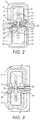
- FIG. 2is an enlarged sectional view of the end effector of FIG. 1 ,
- FIG. 3is an enlarged sectional view of an alternative embodiment of end effector in accordance with the invention.
- FIG. 4is a schematic sectional view of the end effector of FIGS. 1 & 2 showing deformation of the stop members
- FIG. 5is a schematic side view of the end effector of FIGS. 1 & 2 .
- an end effector shown generally at 1comprises an upper jaw 2 pivotably connected to a lower jaw 3 about a pivot 4 .
- Flanges 5are present at the proximal end of upper jaw 2
- flanges 6are present at the proximal end of lower jaw 3 .
- the flanges 5 & 6each have slots 7 through which a drive pin (not shown) extends, such that proximal and distal movement of the drive pin and by means of a drive mechanism (also not shown) which causes the jaws 2 & 3 to pivot between open and closed positions.
- the upper jaw 2comprises a metallic jaw frame 9 , inside which is located a plastics insert 10 .
- a metallic shim 11is present on the inward face of upper jaw 2 , with the shim, insert and jaw frame being encased in an overmoulded body 12 .
- the lower jaw 3comprises a metallic jaw frame 13 , plastics insert 14 and metallic shim 15 , encased in an overmoulded body 16 .
- Inserts 10 & 14have longitudinal grooves 17 & 18 , corresponding also with grooves 19 & 20 in the shims 11 & 15 so as to form an elongate slot for a knife member (not shown).
- Elongate stop members 21 & 22are present on the shim 11 , the stop members running parallel to one another along the length of the upper jaw before meeting in a common nose portion 23 .
- the stop membersare formed of a compliant material such as silicone or a fluoro-elastomer.
- the stop membersare relatively soft in nature, and have a Shore A hardness of between 20 and 80.
- Such a soft and compliant naturemeans that they are capable of deforming by more than 10% when pressure is placed thereon, for example by the jaws being closed with tissue therebetween. That is, the stop members are sufficiently compliant to deform by at least 10% in the direction in which the pressure is applied.
- the height of the stop membersis capable of being reduced by more than 10% when the jaws are closed about tissue. In some embodiments, depending on the softness of the stop members, they may reduce in height by more than 10%, for example by more than 20%, or more than 30%.
- the stop members 21 & 22are moulded onto the shim 11 and secured in place by means of a lower portion 24 received below the shim 11 and joined to the stop members 21 & 22 through holes (not shown) in the shim 11 .
- stop members 25 & 26are present on the shim 15 , the stop members running parallel to one another along the length of the lower jaw before meeting in a common nose portion 27 .
- the stop members 25 & 26are moulded onto the shim 15 and secured in place by means of a lower portion 28 received below the shim 15 in similar fashion to that described with respect to the upper jaw 2 .
- the stop members 25 & 26are offset with respect to the stop members 21 & 22 , with the stop members on the shim 11 running inside those on the shim 15 .
- the shims 11 & 15move adjacent one another, grasping tissue 29 therebetween.
- the stop membersare deformed by the tissue 29 pressing against them, and change shape slightly, as will be further described later.
- the amount by which the stop members deformwill depend on the thickness of the tissue being grasped between the jaws 2 & 3 , and also by the hardness of the tissue. The ability of the stop members to deform allows them to compensate for different thicknesses and hardness of tissue, while still maintaining an appropriate separation between the shims 11 & 15 .
- the shims 11 & 15are supplied with an electrosurgical coagulating current for an electrosurgical generator (not shown) which causes the tissue 29 to become sealed.
- the stop membersensure that the shims 11 & 15 do not come into direct contact, and thereby avoid shorting between the shims They also maintain an appropriate separation between the shims 11 & 15 while the tissue is being sealed, this separation being necessary for the effective sealing of tissue.
- FIG. 3shows an alternative construction in which stop members 25 & 26 are only present on the shim 15 and not on the shim 11 .
- the stop membersare moulded onto the shim 15 as previously described, using a lower portion 28 and holes (not shown) in the shim 15 .
- only two stop members 25 & 26are provided, they separate the shims 11 & 15 as before, and deform to accommodate different tissue grasped between the jaws 2 & 3 .
- FIG. 4shows how the stop members deform when tissue is grasped between the jaws 2 & 3 .
- FIG. 4shows the shims 11 & 15 and elongate stop members 22 & 26 , with tissue 29 grasped between the jaws 2 & 3 .
- the stop membersare generally compliant, having a Shore A hardness of between 20 and 80. This allows the cross-sectional shape of the stop members to change as pressure is applied thereto when the jaws close.
- the cross-sectional shape of the stop members 22 & 26was previously generally triangular, as shown at “A”, although the point of the triangle is rounded in order to prevent the stop members from damaging tissue, particularly by cutting into it.
- the grasping of the tissuedeforms the stop members 22 & 26 into an even more rounded cross-sectional shape as shown at “B”.
- the deformation of the stop memberswill vary, both from tissue to tissue, and also at different longitudinal positions along the stop members, depending on the thickness and hardness of the tissue being grasped. Whatever the deformation, the stop members 22 & 26 will maintain an appropriate spacing between the shims 11 & 15 , the spacing once again depending on the thickness and hardness of the tissue being grasped.
- FIG. 5shows how the separation between the shims 11 & 15 varies along the length of the jaws 2 & 3 .
- the shims 11 & 15 and hence the stop members 22 & 26are relatively close together towards the distal end of the jaws.
- the shims 11 & 15 and hence the stop members 22 & 26are relatively further apart. This means that as the jaws close, they first grasp tissue towards their distal end, with the grasping of tissue progressing gradually towards the proximal end of the jaws.
- the jaws 2 & 3are reasonably flexible, such that they can themselves deform slightly as increased force is applied to the tissue. Not shown in FIG.
- the longitudinal profile of the jawscan be non-linear, such that closing of the jaws causes them to change from one curved shape to another, or from a curved shape to a more linear configuration.
- the compliant nature of the stop membersensures that the spacing between the shims can vary depending on the thickness and hardness of the tissue being held therebetween.
- the elongate compliant stop membersalso allow for longitudinal compression of the stop members along the length thereof, helping to produce a more uniform jaw spacing regardless of where the tissue is grasped along the length of the jaws.
- the jaw spacingis able to change depending on the nature and thickness of the tissue grasped between the jaws, and where and how it is grasped.
Landscapes
- Health & Medical Sciences (AREA)
- Surgery (AREA)
- Engineering & Computer Science (AREA)
- Life Sciences & Earth Sciences (AREA)
- Biomedical Technology (AREA)
- Otolaryngology (AREA)
- Nuclear Medicine, Radiotherapy & Molecular Imaging (AREA)
- Plasma & Fusion (AREA)
- Physics & Mathematics (AREA)
- Heart & Thoracic Surgery (AREA)
- Medical Informatics (AREA)
- Molecular Biology (AREA)
- Animal Behavior & Ethology (AREA)
- General Health & Medical Sciences (AREA)
- Public Health (AREA)
- Veterinary Medicine (AREA)
- Surgical Instruments (AREA)
Abstract
Description
- a handle including an actuating mechanism movable between a first position and a second position,
- a pair of opposing first and second jaw members, movement of the actuating mechanism from its first position to its second position causing at least one of the jaw members to move relative to the other from a first open position in which the jaw members are disposed in a spaced relation relative to one another, to a second closed position in which the jaw members cooperate to grasp tissue therebetween,
- a first sealing electrode located on the first jaw member,
- a second sealing electrode located on the second jaw member,
- electrical connections capable of connecting the instrument to an electrosurgical generator, such that when the jaw members are in their closed position with tissue grasped therebetween, the instrument is capable of sealing the tissue by passing an electrosurgical current into the tissue from the first and second sealing electrodes, and
- one or more stop members disposed on one or both of the first and second sealing electrodes, the one or more stop members being formed of a compliant material with a Shore A hardness of between 20 and 80, such that they are capable of deforming when the jaw members are moved to their closed position with tissue grasped therebetween.
Claims (26)
Applications Claiming Priority (4)
| Application Number | Priority Date | Filing Date | Title |
|---|---|---|---|
| GB1500532.5AGB2534147B (en) | 2015-01-14 | 2015-01-14 | Manufacturing electrosurgical instruments |
| GB1500532.5 | 2015-01-14 | ||
| GB201502479AGB201502479D0 (en) | 2015-02-13 | 2015-02-13 | End effector for electrosurgical instrument |
| GB1502479.7 | 2015-02-13 |
Publications (2)
| Publication Number | Publication Date |
|---|---|
| US20160199124A1 US20160199124A1 (en) | 2016-07-14 |
| US10603103B2true US10603103B2 (en) | 2020-03-31 |
Family
ID=55311565
Family Applications (1)
| Application Number | Title | Priority Date | Filing Date |
|---|---|---|---|
| US14/993,496Active2037-01-17US10603103B2 (en) | 2015-01-14 | 2016-01-12 | End effector for electrosurgical instrument |
Country Status (5)
| Country | Link |
|---|---|
| US (1) | US10603103B2 (en) |
| JP (1) | JP2016129675A (en) |
| CN (1) | CN105769331B (en) |
| DE (1) | DE102016200401B4 (en) |
| GB (1) | GB2535006B (en) |
Cited By (4)
| Publication number | Priority date | Publication date | Assignee | Title |
|---|---|---|---|---|
| US11839422B2 (en) | 2016-09-23 | 2023-12-12 | Cilag Gmbh International | Electrosurgical instrument with fluid diverter |
| US11957342B2 (en) | 2021-11-01 | 2024-04-16 | Cilag Gmbh International | Devices, systems, and methods for detecting tissue and foreign objects during a surgical operation |
| US12023087B2 (en) | 2017-03-15 | 2024-07-02 | Cilag Gmbh International | Electrosurgical instrument with textured jaws |
| US12390264B2 (en) | 2017-09-29 | 2025-08-19 | Cilag Gmbh International | Systems and methods for managing fluid and suction in electrosurgical systems |
Families Citing this family (20)
| Publication number | Priority date | Publication date | Assignee | Title |
|---|---|---|---|---|
| GB2480498A (en) | 2010-05-21 | 2011-11-23 | Ethicon Endo Surgery Inc | Medical device comprising RF circuitry |
| US9333025B2 (en) | 2011-10-24 | 2016-05-10 | Ethicon Endo-Surgery, Llc | Battery initialization clip |
| US10159524B2 (en) | 2014-12-22 | 2018-12-25 | Ethicon Llc | High power battery powered RF amplifier topology |
| US10959771B2 (en) | 2015-10-16 | 2021-03-30 | Ethicon Llc | Suction and irrigation sealing grasper |
| US10973517B2 (en) | 2015-11-13 | 2021-04-13 | Intuitive Surgical Operations, Inc. | Stapler with composite cardan and screw drive |
| US10959806B2 (en) | 2015-12-30 | 2021-03-30 | Ethicon Llc | Energized medical device with reusable handle |
| US10987156B2 (en)* | 2016-04-29 | 2021-04-27 | Ethicon Llc | Electrosurgical instrument with electrically conductive gap setting member and electrically insulative tissue engaging members |
| US20170312018A1 (en)* | 2016-04-29 | 2017-11-02 | Ethicon Endo-Surgery, Llc | Electrosurgical instrument with conductive gap setting member and insulative tissue engaging member having variable dimensions and stiffness |
| US10856934B2 (en) | 2016-04-29 | 2020-12-08 | Ethicon Llc | Electrosurgical instrument with electrically conductive gap setting and tissue engaging members |
| WO2018033932A1 (en)* | 2016-08-16 | 2018-02-22 | Xcellance Medical Technologies Pvt. Ltd. | End effectors for coagulation, sealing and sharp cutting effect |
| US11033325B2 (en) | 2017-02-16 | 2021-06-15 | Cilag Gmbh International | Electrosurgical instrument with telescoping suction port and debris cleaner |
| US11497546B2 (en) | 2017-03-31 | 2022-11-15 | Cilag Gmbh International | Area ratios of patterned coatings on RF electrodes to reduce sticking |
| US10603117B2 (en) | 2017-06-28 | 2020-03-31 | Ethicon Llc | Articulation state detection mechanisms |
| US20210153927A1 (en)* | 2017-06-30 | 2021-05-27 | Intuitive Surgical Operations, Inc. | Electrosurgical instrument with compliant elastomeric electrode |
| US11484358B2 (en) | 2017-09-29 | 2022-11-01 | Cilag Gmbh International | Flexible electrosurgical instrument |
| US11490951B2 (en) | 2017-09-29 | 2022-11-08 | Cilag Gmbh International | Saline contact with electrodes |
| WO2019102552A1 (en)* | 2017-11-22 | 2019-05-31 | オリンパス株式会社 | Treatment tool and treatment tool production method |
| WO2020131692A1 (en) | 2018-12-21 | 2020-06-25 | Intuitive Surgical Operations, Inc. | Surgical instruments having mechanisms for identifying and/or deactivating stapler cartridges |
| CN113905675B (en) | 2019-05-31 | 2025-01-14 | 直观外科手术操作公司 | Staple cartridge for surgical instruments |
| US12402883B2 (en) | 2021-01-08 | 2025-09-02 | Intuitive Surgical Operations, Inc. | Surgical instrument with linear and purse string suture staples |
Citations (24)
| Publication number | Priority date | Publication date | Assignee | Title |
|---|---|---|---|---|
| US20030014053A1 (en) | 1998-10-23 | 2003-01-16 | Nguyen Lap P. | Vessel sealing instrument |
| US20030181932A1 (en) | 2002-03-21 | 2003-09-25 | Terrence Buelna | Surgical clamp pads with deflecting elements |
| US20040122423A1 (en)* | 2001-04-06 | 2004-06-24 | Dycus Sean T. | Vessel sealer and divider with non-conductive stop members |
| EP1486177A2 (en) | 2003-06-13 | 2004-12-15 | Sherwood Services AG | Method of manufacturing jaw assembly |
| US20050021027A1 (en)* | 2003-05-15 | 2005-01-27 | Chelsea Shields | Tissue sealer with non-conductive variable stop members and method of sealing tissue |
| AU2006222705A1 (en) | 2001-04-06 | 2006-10-19 | Covidien Ag | Vessel sealer and divider |
| EP1795140A2 (en) | 2002-10-04 | 2007-06-13 | Sherwood Services AG | Electrode assembly for sealing and cutting tissue and method for performing same |
| US20070265616A1 (en) | 2006-05-10 | 2007-11-15 | Sherwood Services Ag | Vessel sealing instrument with optimized power density |
| US20080015575A1 (en) | 2006-07-14 | 2008-01-17 | Sherwood Services Ag | Vessel sealing instrument with pre-heated electrodes |
| US20090254081A1 (en) | 2008-04-08 | 2009-10-08 | Tyco Electronics Corporation | System and method for surgical jaw assembly |
| US7877852B2 (en) | 2007-09-20 | 2011-02-01 | Tyco Healthcare Group Lp | Method of manufacturing an end effector assembly for sealing tissue |
| US20110060335A1 (en) | 2009-09-10 | 2011-03-10 | Tyco Healthcare Group Lp | Apparatus for Tissue Fusion and Method of Use |
| US7922953B2 (en) | 2005-09-30 | 2011-04-12 | Covidien Ag | Method for manufacturing an end effector assembly |
| EP2425791A1 (en) | 2010-09-07 | 2012-03-07 | Tyco Healthcare Group, LP | Dynamic and static bipolar electrical sealing and cutting device |
| US20120083783A1 (en) | 2010-10-01 | 2012-04-05 | Ethicon Endo-Surgery, Inc. | Surgical instrument with jaw member |
| US20120265241A1 (en) | 2011-04-12 | 2012-10-18 | Tyco Healthcare Group Lp | Surgical Forceps and Method of Manufacturing Thereof |
| US20130085496A1 (en) | 2011-09-29 | 2013-04-04 | Tyco Healthcare Group Lp | Surgical Forceps |
| US20130226177A1 (en) | 2012-02-24 | 2013-08-29 | Tyco Healthcare Group Lp | Vessel Sealing Instrument with Reduced Thermal Spread and Method of Manufacture Therefor |
| US20130255063A1 (en) | 2012-03-29 | 2013-10-03 | Tyco Healthcare Group Lp | Electrosurgical Forceps and Method of Manufacturing the Same |
| EP2687176A1 (en) | 2012-07-17 | 2014-01-22 | Covidien LP | Gap control via overmold teeth and hard stops |
| US20140194875A1 (en) | 2013-01-10 | 2014-07-10 | Covidien Lp | Surgical forceps |
| US20150018816A1 (en) | 2013-07-11 | 2015-01-15 | Covidien Lp | Electrode assembly for use with surgical instruments |
| WO2015197395A1 (en) | 2014-06-25 | 2015-12-30 | Aesculap Ag | Electrosurgical instrument and jaw part for same |
| US9713491B2 (en) | 2013-02-19 | 2017-07-25 | Covidien Lp | Method for manufacturing an electrode assembly configured for use with an electrosurigcal instrument |
Family Cites Families (2)
| Publication number | Priority date | Publication date | Assignee | Title |
|---|---|---|---|---|
| US7753908B2 (en) | 2002-02-19 | 2010-07-13 | Endoscopic Technologies, Inc. (Estech) | Apparatus for securing an electrophysiology probe to a clamp |
| AU2003205316A1 (en) | 2002-01-22 | 2003-09-02 | Sciogen Llc | Electrosurgical instrument and method of use |
- 2015
- 2015-12-23GBGB1522803.4Apatent/GB2535006B/ennot_activeExpired - Fee Related
- 2016
- 2016-01-12CNCN201610017914.8Apatent/CN105769331B/enactiveActive
- 2016-01-12USUS14/993,496patent/US10603103B2/enactiveActive
- 2016-01-13JPJP2016004658Apatent/JP2016129675A/enactivePending
- 2016-01-14DEDE102016200401.8Apatent/DE102016200401B4/enactiveActive
Patent Citations (30)
| Publication number | Priority date | Publication date | Assignee | Title |
|---|---|---|---|---|
| US20030014053A1 (en) | 1998-10-23 | 2003-01-16 | Nguyen Lap P. | Vessel sealing instrument |
| AU2006222705A1 (en) | 2001-04-06 | 2006-10-19 | Covidien Ag | Vessel sealer and divider |
| US20040122423A1 (en)* | 2001-04-06 | 2004-06-24 | Dycus Sean T. | Vessel sealer and divider with non-conductive stop members |
| JP2004532676A (en) | 2001-04-06 | 2004-10-28 | シャーウッド・サービシーズ・アクチェンゲゼルシャフト | Vascular sealer and divider with non-conductive stop member |
| US8241284B2 (en) | 2001-04-06 | 2012-08-14 | Covidien Ag | Vessel sealer and divider with non-conductive stop members |
| US7473253B2 (en) | 2001-04-06 | 2009-01-06 | Covidien Ag | Vessel sealer and divider with non-conductive stop members |
| US6942676B2 (en)* | 2002-03-21 | 2005-09-13 | Novare Surgical Systems, Inc. | Surgical clamp pads with deflecting elements |
| US20030181932A1 (en) | 2002-03-21 | 2003-09-25 | Terrence Buelna | Surgical clamp pads with deflecting elements |
| EP1795140A2 (en) | 2002-10-04 | 2007-06-13 | Sherwood Services AG | Electrode assembly for sealing and cutting tissue and method for performing same |
| US20050021027A1 (en)* | 2003-05-15 | 2005-01-27 | Chelsea Shields | Tissue sealer with non-conductive variable stop members and method of sealing tissue |
| US7150097B2 (en) | 2003-06-13 | 2006-12-19 | Sherwood Services Ag | Method of manufacturing jaw assembly for vessel sealer and divider |
| EP1486177A2 (en) | 2003-06-13 | 2004-12-15 | Sherwood Services AG | Method of manufacturing jaw assembly |
| US7922953B2 (en) | 2005-09-30 | 2011-04-12 | Covidien Ag | Method for manufacturing an end effector assembly |
| US20070265616A1 (en) | 2006-05-10 | 2007-11-15 | Sherwood Services Ag | Vessel sealing instrument with optimized power density |
| US20080015575A1 (en) | 2006-07-14 | 2008-01-17 | Sherwood Services Ag | Vessel sealing instrument with pre-heated electrodes |
| US7877852B2 (en) | 2007-09-20 | 2011-02-01 | Tyco Healthcare Group Lp | Method of manufacturing an end effector assembly for sealing tissue |
| US20090254081A1 (en) | 2008-04-08 | 2009-10-08 | Tyco Electronics Corporation | System and method for surgical jaw assembly |
| US20110060335A1 (en) | 2009-09-10 | 2011-03-10 | Tyco Healthcare Group Lp | Apparatus for Tissue Fusion and Method of Use |
| EP2425791A1 (en) | 2010-09-07 | 2012-03-07 | Tyco Healthcare Group, LP | Dynamic and static bipolar electrical sealing and cutting device |
| US20120083783A1 (en) | 2010-10-01 | 2012-04-05 | Ethicon Endo-Surgery, Inc. | Surgical instrument with jaw member |
| US20120265241A1 (en) | 2011-04-12 | 2012-10-18 | Tyco Healthcare Group Lp | Surgical Forceps and Method of Manufacturing Thereof |
| US20130085496A1 (en) | 2011-09-29 | 2013-04-04 | Tyco Healthcare Group Lp | Surgical Forceps |
| US20130226177A1 (en) | 2012-02-24 | 2013-08-29 | Tyco Healthcare Group Lp | Vessel Sealing Instrument with Reduced Thermal Spread and Method of Manufacture Therefor |
| US20130255063A1 (en) | 2012-03-29 | 2013-10-03 | Tyco Healthcare Group Lp | Electrosurgical Forceps and Method of Manufacturing the Same |
| EP2687176A1 (en) | 2012-07-17 | 2014-01-22 | Covidien LP | Gap control via overmold teeth and hard stops |
| US20140025073A1 (en) | 2012-07-17 | 2014-01-23 | Covidien Lp | Gap control via overmold teeth and hard stops |
| US20140194875A1 (en) | 2013-01-10 | 2014-07-10 | Covidien Lp | Surgical forceps |
| US9713491B2 (en) | 2013-02-19 | 2017-07-25 | Covidien Lp | Method for manufacturing an electrode assembly configured for use with an electrosurigcal instrument |
| US20150018816A1 (en) | 2013-07-11 | 2015-01-15 | Covidien Lp | Electrode assembly for use with surgical instruments |
| WO2015197395A1 (en) | 2014-06-25 | 2015-12-30 | Aesculap Ag | Electrosurgical instrument and jaw part for same |
Non-Patent Citations (13)
| Title |
|---|
| Combined Search and Examination Report Under Sections 17 & 18(3) in UK Application No. GB 1522803.4, dated May 26, 2016. |
| Examination Report under section 18(3) for corresponding United Kingdom Application No. GB1522803.4 dated Sep. 5, 2016. |
| Jul. 2, 2019 Office Action issued in Chinese Patent Application No. 201610017914.8. |
| Letter from UKIPO advising of error in search report dated May 26, 2016 in United Kingdom Patent Application No. GB1522803.4 dated Aug. 23, 2016 and attached Corrected Search Report under Section 17. |
| Oct. 1, 2019 Office Action issued in Japanese Patent Application No. 2016-004658. |
| Oct. 29, 2018 Office Action issued in Chinese Patent Application No. 201610017914.8. |
| Search Report in UK Application No. GB 1500532.5, dated Jun. 5, 2015. |
| Search Report in UK Application No. GB 1502479.7, dated Jul. 10, 2015. |
| Search Report under Section 17(6) for claims 19 and 20 in United Kingdom Patent Application No. GB1522803.4 dated Aug. 23, 2016. |
| U.S. Appl. No. 14/992,137, filed Jan. 11, 2016, Jones, et al. |
| U.S. Appl. No. 14/992,193, filed Jan. 11, 2016, Thomas, et al. |
| U.S. Appl. No. 14/993,408, filed Jan. 12, 2016, Thomas, et al. |
| U.S. Appl. No. 14/994,464, filed Jan. 13, 2016, Jones. |
Cited By (5)
| Publication number | Priority date | Publication date | Assignee | Title |
|---|---|---|---|---|
| US11839422B2 (en) | 2016-09-23 | 2023-12-12 | Cilag Gmbh International | Electrosurgical instrument with fluid diverter |
| US12295644B2 (en) | 2016-09-23 | 2025-05-13 | Cilag Gmbh International | Electrosurgical instrument with fluid diverter |
| US12023087B2 (en) | 2017-03-15 | 2024-07-02 | Cilag Gmbh International | Electrosurgical instrument with textured jaws |
| US12390264B2 (en) | 2017-09-29 | 2025-08-19 | Cilag Gmbh International | Systems and methods for managing fluid and suction in electrosurgical systems |
| US11957342B2 (en) | 2021-11-01 | 2024-04-16 | Cilag Gmbh International | Devices, systems, and methods for detecting tissue and foreign objects during a surgical operation |
Also Published As
| Publication number | Publication date |
|---|---|
| DE102016200401A1 (en) | 2016-07-14 |
| GB2535006A9 (en) | 2016-09-14 |
| US20160199124A1 (en) | 2016-07-14 |
| DE102016200401B4 (en) | 2024-06-20 |
| GB2535006B (en) | 2018-12-12 |
| GB2535006A (en) | 2016-08-10 |
| GB201522803D0 (en) | 2016-02-03 |
| CN105769331A (en) | 2016-07-20 |
| CN105769331B (en) | 2020-10-23 |
| JP2016129675A (en) | 2016-07-21 |
Similar Documents
| Publication | Publication Date | Title |
|---|---|---|
| US10603103B2 (en) | End effector for electrosurgical instrument | |
| IE87065B1 (en) | End effector for electrosurgical instrument | |
| US11957404B2 (en) | Two-stage electrosurgical device for vessel sealing | |
| CN106491203B (en) | Instrument for grasping, dissecting and/or coagulating biological tissue | |
| US12329441B2 (en) | Two-stage electrosurgical device for vessel sealing | |
| KR102003099B1 (en) | Surgical instrument | |
| US8961513B2 (en) | Surgical tissue sealer | |
| US10806508B2 (en) | Method for manufacturing an electrode assembly configured for use with an electrosurgical instrument | |
| US10932789B2 (en) | Ligation clip with latching and retention features | |
| US20200046359A1 (en) | Ligation clip with improved hinge | |
| CN101969874B (en) | Surgical instrument | |
| US10413354B2 (en) | End effector for electrosurgical instrument | |
| US20110060335A1 (en) | Apparatus for Tissue Fusion and Method of Use | |
| KR20190139767A (en) | Laparoscopic forceps instrument | |
| EP1958583A3 (en) | Vessel sealing instrument with electrical cutting mechanism | |
| US20150209102A1 (en) | Surgical instrument | |
| US12343068B2 (en) | Electrosurgical instrument | |
| US20220218408A1 (en) | Cutting Instrument | |
| CN219331788U (en) | Auricle closing device | |
| RU2844008C2 (en) | Electrosurgical instrument for dissection or combined coagulation and dissection of biological tissue, as well as a method for manufacturing a resilient anvil therefor |
Legal Events
| Date | Code | Title | Description |
|---|---|---|---|
| AS | Assignment | Owner name:GYRUS MEDICAL LIMITED, UNITED KINGDOM Free format text:ASSIGNMENT OF ASSIGNORS INTEREST;ASSIGNORS:THOMAS, DANIEL JOHN;JONES, LEWIS MEURIG;JENKINS, ANDREW EDWARD;REEL/FRAME:037466/0268 Effective date:20160111 | |
| STPP | Information on status: patent application and granting procedure in general | Free format text:DOCKETED NEW CASE - READY FOR EXAMINATION | |
| STPP | Information on status: patent application and granting procedure in general | Free format text:NON FINAL ACTION MAILED | |
| STPP | Information on status: patent application and granting procedure in general | Free format text:NON FINAL ACTION MAILED | |
| STPP | Information on status: patent application and granting procedure in general | Free format text:RESPONSE TO NON-FINAL OFFICE ACTION ENTERED AND FORWARDED TO EXAMINER | |
| STPP | Information on status: patent application and granting procedure in general | Free format text:NOTICE OF ALLOWANCE MAILED -- APPLICATION RECEIVED IN OFFICE OF PUBLICATIONS | |
| STPP | Information on status: patent application and granting procedure in general | Free format text:PUBLICATIONS -- ISSUE FEE PAYMENT RECEIVED | |
| STCF | Information on status: patent grant | Free format text:PATENTED CASE | |
| MAFP | Maintenance fee payment | Free format text:PAYMENT OF MAINTENANCE FEE, 4TH YEAR, LARGE ENTITY (ORIGINAL EVENT CODE: M1551); ENTITY STATUS OF PATENT OWNER: LARGE ENTITY Year of fee payment:4 | |
| AS | Assignment | Owner name:GYRUS ACMI, INC, TENNESSEE Free format text:ASSIGNMENT OF ASSIGNORS INTEREST;ASSIGNOR:GYRUS MEDICAL LIMITED;REEL/FRAME:066000/0508 Effective date:20230321 |