US10603072B2 - Methods for preparing a skin graft without culturing or use of biologics - Google Patents
Methods for preparing a skin graft without culturing or use of biologicsDownload PDFInfo
- Publication number
- US10603072B2 US10603072B2US15/349,116US201615349116AUS10603072B2US 10603072 B2US10603072 B2US 10603072B2US 201615349116 AUS201615349116 AUS 201615349116AUS 10603072 B2US10603072 B2US 10603072B2
- Authority
- US
- United States
- Prior art keywords
- skin
- substrate
- graft
- micrografts
- blister
- Prior art date
- Legal status (The legal status is an assumption and is not a legal conclusion. Google has not performed a legal analysis and makes no representation as to the accuracy of the status listed.)
- Active
Links
- 238000000034methodMethods0.000titleclaimsabstractdescription77
- 229960000074biopharmaceuticalDrugs0.000titleclaimsabstractdescription13
- 238000012258culturingMethods0.000titleclaimsabstractdescription12
- 239000000758substrateSubstances0.000claimsdescription185
- 238000003306harvestingMethods0.000claimsdescription20
- 238000012546transferMethods0.000claimsdescription19
- 238000010438heat treatmentMethods0.000claimsdescription7
- 230000033001locomotionEffects0.000claimsdescription7
- 210000000270basal cellAnatomy0.000claimsdescription4
- 210000003491skinAnatomy0.000description95
- 210000001519tissueAnatomy0.000description26
- 238000005520cutting processMethods0.000description22
- 239000000463materialSubstances0.000description21
- 206010047642VitiligoDiseases0.000description19
- 210000004027cellAnatomy0.000description12
- 210000000434stratum corneumAnatomy0.000description12
- 230000001070adhesive effectEffects0.000description9
- 210000004207dermisAnatomy0.000description9
- 239000012530fluidSubstances0.000description9
- 206010052428WoundDiseases0.000description8
- 208000027418Wounds and injuryDiseases0.000description8
- 239000000853adhesiveSubstances0.000description8
- 210000002752melanocyteAnatomy0.000description8
- 210000002615epidermisAnatomy0.000description7
- 230000007246mechanismEffects0.000description7
- 230000008439repair processEffects0.000description7
- 210000002510keratinocyteAnatomy0.000description6
- 230000008569processEffects0.000description6
- 230000035614depigmentationEffects0.000description5
- 235000015097nutrientsNutrition0.000description5
- 239000012858resilient materialSubstances0.000description5
- 230000006870functionEffects0.000description4
- 208000014674injuryDiseases0.000description4
- 238000004519manufacturing processMethods0.000description4
- 229920002635polyurethanePolymers0.000description4
- 239000004814polyurethaneSubstances0.000description4
- 238000002360preparation methodMethods0.000description4
- 230000008733traumaEffects0.000description4
- 238000009736wettingMethods0.000description4
- 206010060872Transplant failureDiseases0.000description3
- 208000025865UlcerDiseases0.000description3
- 230000015572biosynthetic processEffects0.000description3
- 210000004204blood vesselAnatomy0.000description3
- 238000004140cleaningMethods0.000description3
- 230000002500effect on skinEffects0.000description3
- 229910052751metalInorganic materials0.000description3
- 239000002184metalSubstances0.000description3
- 231100000397ulcerToxicity0.000description3
- 210000000689upper legAnatomy0.000description3
- 238000010792warmingMethods0.000description3
- 102000008186CollagenHuman genes0.000description2
- 108010035532CollagenProteins0.000description2
- FAPWRFPIFSIZLT-UHFFFAOYSA-MSodium chlorideChemical compound[Na+].[Cl-]FAPWRFPIFSIZLT-UHFFFAOYSA-M0.000description2
- 102000004142TrypsinHuman genes0.000description2
- 108090000631TrypsinProteins0.000description2
- 210000003484anatomyAnatomy0.000description2
- 230000004888barrier functionEffects0.000description2
- 229920001436collagenPolymers0.000description2
- 210000002808connective tissueAnatomy0.000description2
- 230000006378damageEffects0.000description2
- 201000010099diseaseDiseases0.000description2
- 208000037265diseases, disorders, signs and symptomsDiseases0.000description2
- 210000004177elastic tissueAnatomy0.000description2
- 239000000835fiberSubstances0.000description2
- 239000003102growth factorSubstances0.000description2
- 208000015181infectious diseaseDiseases0.000description2
- 238000005461lubricationMethods0.000description2
- 230000037380skin damageEffects0.000description2
- 210000000438stratum basaleAnatomy0.000description2
- 239000000126substanceSubstances0.000description2
- 238000001356surgical procedureMethods0.000description2
- 239000012588trypsinSubstances0.000description2
- XLYOFNOQVPJJNP-UHFFFAOYSA-NwaterSubstancesOXLYOFNOQVPJJNP-UHFFFAOYSA-N0.000description2
- KIUKXJAPPMFGSW-DNGZLQJQSA-N(2S,3S,4S,5R,6R)-6-[(2S,3R,4R,5S,6R)-3-Acetamido-2-[(2S,3S,4R,5R,6R)-6-[(2R,3R,4R,5S,6R)-3-acetamido-2,5-dihydroxy-6-(hydroxymethyl)oxan-4-yl]oxy-2-carboxy-4,5-dihydroxyoxan-3-yl]oxy-5-hydroxy-6-(hydroxymethyl)oxan-4-yl]oxy-3,4,5-trihydroxyoxane-2-carboxylic acidChemical compoundCC(=O)N[C@H]1[C@H](O)O[C@H](CO)[C@@H](O)[C@@H]1O[C@H]1[C@H](O)[C@@H](O)[C@H](O[C@H]2[C@@H]([C@@H](O[C@H]3[C@@H]([C@@H](O)[C@H](O)[C@H](O3)C(O)=O)O)[C@H](O)[C@@H](CO)O2)NC(C)=O)[C@@H](C(O)=O)O1KIUKXJAPPMFGSW-DNGZLQJQSA-N0.000description1
- 208000023275Autoimmune diseaseDiseases0.000description1
- 241000894006BacteriaSpecies0.000description1
- 0CC(*CC1)C1OCChemical compoundCC(*CC1)C1OC0.000description1
- OKTJSMMVPCPJKN-UHFFFAOYSA-NCarbonChemical group[C]OKTJSMMVPCPJKN-UHFFFAOYSA-N0.000description1
- 208000009043Chemical BurnsDiseases0.000description1
- 229920001287Chondroitin sulfatePolymers0.000description1
- 208000017667Chronic DiseaseDiseases0.000description1
- 206010056340Diabetic ulcerDiseases0.000description1
- 206010014989Epidermolysis bullosaDiseases0.000description1
- 206010063560Excessive granulation tissueDiseases0.000description1
- 102000003886GlycoproteinsHuman genes0.000description1
- 108090000288GlycoproteinsProteins0.000description1
- 229920002683GlycosaminoglycanPolymers0.000description1
- 208000035901Ischaemic ulcerDiseases0.000description1
- 108010076876KeratinsProteins0.000description1
- 102000011782KeratinsHuman genes0.000description1
- 241001465754MetazoaSpecies0.000description1
- 206010028980NeoplasmDiseases0.000description1
- 208000012641Pigmentation diseaseDiseases0.000description1
- 239000004952PolyamideSubstances0.000description1
- 239000004698PolyethyleneSubstances0.000description1
- 108010081750ReticulinProteins0.000description1
- 206010053615Thermal burnDiseases0.000description1
- 206010052779Transplant rejectionsDiseases0.000description1
- 230000009471actionEffects0.000description1
- 230000002411adverseEffects0.000description1
- 125000001931aliphatic groupChemical group0.000description1
- 238000003491arrayMethods0.000description1
- 230000000712assemblyEffects0.000description1
- 238000000429assemblyMethods0.000description1
- 230000001580bacterial effectEffects0.000description1
- 210000002469basement membraneAnatomy0.000description1
- 239000000560biocompatible materialSubstances0.000description1
- 230000033228biological regulationEffects0.000description1
- 239000008280bloodSubstances0.000description1
- 210000004369bloodAnatomy0.000description1
- 230000037396body weightEffects0.000description1
- 201000011510cancerDiseases0.000description1
- 230000010261cell growthEffects0.000description1
- 230000008859changeEffects0.000description1
- 229940107200chondroitin sulfatesDrugs0.000description1
- 239000002131composite materialSubstances0.000description1
- 230000001351cycling effectEffects0.000description1
- 230000034994deathEffects0.000description1
- 230000007123defenseEffects0.000description1
- 230000008021depositionEffects0.000description1
- 230000002074deregulated effectEffects0.000description1
- 238000010586diagramMethods0.000description1
- 230000004069differentiationEffects0.000description1
- 238000009792diffusion processMethods0.000description1
- 210000003981ectodermAnatomy0.000description1
- 230000007613environmental effectEffects0.000description1
- 239000003256environmental substanceSubstances0.000description1
- 210000000981epitheliumAnatomy0.000description1
- 235000020774essential nutrientsNutrition0.000description1
- 230000002349favourable effectEffects0.000description1
- 210000002950fibroblastAnatomy0.000description1
- 230000003176fibrotic effectEffects0.000description1
- 230000008014freezingEffects0.000description1
- 238000007710freezingMethods0.000description1
- 210000004392genitaliaAnatomy0.000description1
- 239000011521glassSubstances0.000description1
- 239000008187granular materialSubstances0.000description1
- 210000001126granulation tissueAnatomy0.000description1
- 230000012010growthEffects0.000description1
- 210000004247handAnatomy0.000description1
- 230000035876healingEffects0.000description1
- 210000003630histaminocyteAnatomy0.000description1
- 229920002674hyaluronanPolymers0.000description1
- 229960003160hyaluronic acidDrugs0.000description1
- 239000000416hydrocolloidSubstances0.000description1
- 208000000069hyperpigmentationDiseases0.000description1
- 230000003810hyperpigmentationEffects0.000description1
- 238000010348incorporationMethods0.000description1
- 238000009413insulationMethods0.000description1
- 230000003993interactionEffects0.000description1
- 230000029774keratinocyte migrationEffects0.000description1
- 230000003902lesionEffects0.000description1
- 229920000092linear low density polyethylenePolymers0.000description1
- 239000004707linear low-density polyethyleneSubstances0.000description1
- 229920001684low density polyethylenePolymers0.000description1
- 239000004702low-density polyethyleneSubstances0.000description1
- 210000003716mesodermAnatomy0.000description1
- 230000005012migrationEffects0.000description1
- 238000013508migrationMethods0.000description1
- 230000001338necrotic effectEffects0.000description1
- 210000001640nerve endingAnatomy0.000description1
- 210000000056organAnatomy0.000description1
- 239000002245particleSubstances0.000description1
- 244000052769pathogenSpecies0.000description1
- 229920003023plasticPolymers0.000description1
- 239000004033plasticSubstances0.000description1
- 229920002647polyamidePolymers0.000description1
- 229920000728polyesterPolymers0.000description1
- -1polyethylenePolymers0.000description1
- 229920000573polyethylenePolymers0.000description1
- 229920001296polysiloxanePolymers0.000description1
- 238000012545processingMethods0.000description1
- 230000000750progressive effectEffects0.000description1
- 230000002062proliferating effectEffects0.000description1
- 230000035755proliferationEffects0.000description1
- 208000009954pyoderma gangrenosumDiseases0.000description1
- 238000001959radiotherapyMethods0.000description1
- 230000000250revascularizationEffects0.000description1
- 230000035807sensationEffects0.000description1
- 238000000926separation methodMethods0.000description1
- 229960003600silver sulfadiazineDrugs0.000description1
- UEJSSZHHYBHCEL-UHFFFAOYSA-Nsilver(1+) sulfadiazinateChemical compound[Ag+].C1=CC(N)=CC=C1S(=O)(=O)[N-]C1=NC=CC=N1UEJSSZHHYBHCEL-UHFFFAOYSA-N0.000description1
- 206010040882skin lesionDiseases0.000description1
- 231100000444skin lesionToxicity0.000description1
- 210000000273spinal nerve rootAnatomy0.000description1
- 239000007921spraySubstances0.000description1
- 229910001220stainless steelInorganic materials0.000description1
- 239000010935stainless steelSubstances0.000description1
- 238000010561standard procedureMethods0.000description1
- 230000003068static effectEffects0.000description1
- 210000000130stem cellAnatomy0.000description1
- 238000003860storageMethods0.000description1
- 210000000498stratum granulosumAnatomy0.000description1
- 230000004083survival effectEffects0.000description1
- 230000001228trophic effectEffects0.000description1
- 210000001113umbilicusAnatomy0.000description1
- 210000000707wristAnatomy0.000description1
Images


Classifications
- A—HUMAN NECESSITIES
- A61—MEDICAL OR VETERINARY SCIENCE; HYGIENE
- A61B—DIAGNOSIS; SURGERY; IDENTIFICATION
- A61B17/00—Surgical instruments, devices or methods
- A61B17/32—Surgical cutting instruments
- A61B17/322—Skin grafting apparatus
- A—HUMAN NECESSITIES
- A61—MEDICAL OR VETERINARY SCIENCE; HYGIENE
- A61B—DIAGNOSIS; SURGERY; IDENTIFICATION
- A61B17/00—Surgical instruments, devices or methods
- A61B17/30—Surgical pincettes, i.e. surgical tweezers without pivotal connections
- A—HUMAN NECESSITIES
- A61—MEDICAL OR VETERINARY SCIENCE; HYGIENE
- A61F—FILTERS IMPLANTABLE INTO BLOOD VESSELS; PROSTHESES; DEVICES PROVIDING PATENCY TO, OR PREVENTING COLLAPSING OF, TUBULAR STRUCTURES OF THE BODY, e.g. STENTS; ORTHOPAEDIC, NURSING OR CONTRACEPTIVE DEVICES; FOMENTATION; TREATMENT OR PROTECTION OF EYES OR EARS; BANDAGES, DRESSINGS OR ABSORBENT PADS; FIRST-AID KITS
- A61F2/00—Filters implantable into blood vessels; Prostheses, i.e. artificial substitutes or replacements for parts of the body; Appliances for connecting them with the body; Devices providing patency to, or preventing collapsing of, tubular structures of the body, e.g. stents
- A61F2/02—Prostheses implantable into the body
- A61F2/10—Hair or skin implants
- A61F2/105—Skin implants, e.g. artificial skin
- A—HUMAN NECESSITIES
- A61—MEDICAL OR VETERINARY SCIENCE; HYGIENE
- A61B—DIAGNOSIS; SURGERY; IDENTIFICATION
- A61B17/00—Surgical instruments, devices or methods
- A61B2017/00743—Type of operation; Specification of treatment sites
- A61B2017/00747—Dermatology
- A—HUMAN NECESSITIES
- A61—MEDICAL OR VETERINARY SCIENCE; HYGIENE
- A61B—DIAGNOSIS; SURGERY; IDENTIFICATION
- A61B17/00—Surgical instruments, devices or methods
- A61B2017/00969—Surgical instruments, devices or methods used for transplantation
- A—HUMAN NECESSITIES
- A61—MEDICAL OR VETERINARY SCIENCE; HYGIENE
- A61B—DIAGNOSIS; SURGERY; IDENTIFICATION
- A61B17/00—Surgical instruments, devices or methods
- A61B17/30—Surgical pincettes, i.e. surgical tweezers without pivotal connections
- A61B2017/306—Surgical pincettes, i.e. surgical tweezers without pivotal connections holding by means of suction
- A—HUMAN NECESSITIES
- A61—MEDICAL OR VETERINARY SCIENCE; HYGIENE
- A61B—DIAGNOSIS; SURGERY; IDENTIFICATION
- A61B17/00—Surgical instruments, devices or methods
- A61B17/32—Surgical cutting instruments
- A61B17/322—Skin grafting apparatus
- A61B2017/3225—Skin grafting apparatus with processing of harvested tissue
Definitions
- the present inventiongenerally relates to methods for preparing a skin graft without culturing or use of biologics.
- Skinis the largest organ of the human body, representing approximately 16% of a person's total body weight. Because it interfaces with the environment, skin has an important function in body defense, acting as an anatomical barrier from pathogens and other environmental substances. Skin also provides a semi-permeable barrier that prevents excessive fluid loss while ensuring that essential nutrients are not washed out of the body. Other functions of skin include insulation, temperature regulation, and sensation. Skin tissue may be subject to many forms of damage, including burns, trauma, disease, and depigmentation (e.g., vitiligo).
- Skin graftsare often used to repair such skin damage.
- Skin graftingis a surgical procedure in which a section of skin is removed from one area of a person's body (autograft), removed from another human source (allograft), or removed from another animal (xenograft), and transplanted to a recipient site of a patient, such as a wound site.
- autografta surgical procedure in which a section of skin is removed from one area of a person's body
- autograftremoved from another human source
- xenograftxenograft
- Complicationsmay include: graft failure; rejection of the skin graft; infections at donor or recipient sites; or autograft donor sites oozing fluid and blood as they heal. Certain of these complications (e.g., graft failure and rejection of the skin graft) may be mitigated by using an autograft instead of an allograft or a xenograft.
- a problem encountered when using an autograftis that skin is taken from another area of a person's body to produce the graft, resulting in trauma and wound generation at the donor site.
- the size of the graftmatches the size of the recipient site, and thus a large recipient site requires removal of a large section of skin from a donor site.
- the size of the section of skin removed from the donor siteincreases, so does the probability that the donor site will not heal properly, requiring additional treatment and intervention.
- the size of the section of skin removed from the donor siteincreases, so does the possibility of infection.
- the present inventiongenerally relates to methods for preparing skin grafts without culturing or use of biologics. Instead, methods of the invention use mechanical techniques to produce a graft that can repair a recipient site that is larger than a donor site from which the graft is obtained.
- Methods of the inventioninvolve harvesting a skin graft from a donor site, preparing the graft for transfer to a recipient site without culturing the graft or applying biologics to the graft, and transferring said graft to a recipient site. Preparing may include placing the harvested skin graft on a first substrate, generating a plurality of micrografts, and stretching the first substrate.
- methods of the inventionfurther include transferring the graft from the first substrate to a second substrate.
- Another aspect of the inventionprovides a method of treating vitiligo, including harvesting a skin graft from a donor site, preparing the graft for transfer to a recipient site without culturing the graft or applying biologics to the graft, and transferring said graft to a recipient site, wherein the recipient site is an area of depigmented skin that has been prepared to receive the skin graft.
- FIG. 1is a schematic, perspective, cross-sectional drawing showing the anatomy of skin.
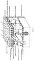
- FIG. 2Ais an exploded perspective view of a device for generating and harvesting a plurality of micrografts.
- FIG. 2Bprovides a top view of the assembled device of FIG. 2A .
- FIG. 2Cprovides a side view of the assembled device of FIG. 2A .
- FIGS. 3A-3Iprovides a schematic of an exemplary process for preparing a skin graft according to methods of the invention.
- FIG. 3Ashows an excised epidermal blister sitting on a sterile cutting surface with a sterile cutter tool above.
- FIG. 3Bshows the cutter tool cutting the epidermal blister to generate an array of micrografts.
- FIG. 3Cshows the array of micrografts that has been produced by the cutting tool sitting on a first substrate.
- FIG. 3Dshows the first substrate placed into an expansion device.
- a second substrateis placed into the assembly cap above.
- FIG. 3Eshows the expansion process. As the first substrate expands, the micrografts move apart.
- FIG. 3Ashows an excised epidermal blister sitting on a sterile cutting surface with a sterile cutter tool above.
- FIG. 3Bshows the cutter tool cutting the epidermal blister to generate an array of micrografts.
- FIG. 3Cshows the array of micrografts that has been produced by the
- FIG. 3Fshows that as the first substrate flattens against the assembly cap, the micrografts are transferred to the second substrate.
- FIG. 3Gshows the completed expansion process and that the micrografts have been transferred to the second substrate.
- FIG. 3Hshows removal of the assembly cap having the second substrate and expanded micrografts from the expansion device.
- FIG. 3Ishows removal of the second substrate having the expanded micrografts from the assembly cap of the expansion device.
- FIG. 4Ais schematic side view of a device of the invention for raising a suction blister.
- FIG. 4Bis a schematic top view of a portion of the device of FIG. 4A .
- FIG. 5Ais a schematic view of another device of the invention for raising a suction blister.
- FIG. 5Bis a schematic view of another device of the invention for raising a suction blister.
- FIG. 5Cis a schematic view of another device of the invention for raising a suction blister.
- FIG. 5Dis a schematic view of another device of the invention for raising a suction blister.
- FIG. 6is a process chart showing steps for treating vitiligo using methods of the invention.
- the skinconsists of 2 layers.
- the outer layer, or epidermisis derived from ectoderm, and the thicker inner layer, or dermis, is derived from mesoderm.
- the epidermisconstitutes about 5% of the skin, and the remaining 95% is dermis.
- FIG. 1provides a diagram showing the anatomy of skin. The skin varies in thickness depending on anatomic location, gender, and age of the individual.
- the epidermisthe more external of the two layers, is a stratified squamous epithelium consisting primarily of melanocytes and keratinocytes in progressive stages of differentiation from deeper to more superficial layers.
- the epidermishas no blood vessels; thus, it must receive nutrients by diffusion from the underlying dermis through the basement membrane, which separates the 2 layers.
- the dermisis a more complex structure. It is composed of 2 layers, the more superficial papillary dermis and the deeper reticular dermis.
- the papillary dermisis thinner, including loose connective tissue that contains capillaries, elastic fibers, reticular fibers, and some collagen.
- the reticular dermisincludes a thicker layer of dense connective tissue containing larger blood vessels, closely interlaced elastic fibers, and coarse, branching collagen fibers arranged in layers parallel to the surface.
- the reticular layeralso contains fibroblasts, mast cells, nerve endings, lymphatics, and some epidermal appendages.
- Surrounding the components of the dermisis the gel-like ground substance composed of mucopolysaccharides (primarily hyaluronic acid), chondroitin sulfates, and glycoproteins.
- a substantially epidermal graft according to the inventionis more likely to adapt to the characteristics of the recipient site.
- the present inventiongenerally relates to methods and devices for preparing a skin graft.
- methods of the inventionallow for preparing a skin graft for transfer to a recipient site without culturing the graft or applying biologics to the graft. Rather, methods of the invention use mechanical techniques for preparation of a skin graft.
- methods of the inventioninvolve harvesting a plurality of skin grafts from a subject, applying the grafts to a first substrate, stretching the first substrate, and transferring the grafts from the first substrate to a second substrate for application to a patient recipient site.
- Harvesting of the skin graftsmay be accomplished by any technique known in the art, and the technique employed will depend on the type of graft required (e.g., epidermal graft, split thickness graft, or full thickness graft).
- An epidermal graftrefers to a graft that consists of substantially epidermal skin and does not include any substantial portion of the dermal layer.
- a split thickness graftrefers to a graft that includes sheets of superficial (epithelial) and some deep layers (dermal) of skin.
- a full-thickness graftrefers to a graft that includes all of the layers of the skin including blood vessels.
- a device as shown in FIG. 2 panels A-Cis used to obtain the plurality of skin grafts.
- Device 200includes a frame 201 and a lid 202 . Fitted into the frame is a bottom plate 203 , a cutter grid plate 204 , a cutter plate 205 , and a top plate 206 .
- the bottom plate 203 , the cutter plate 205 , and the top plate 206each include a hole array 211 . Once assembled, the hole array 211 of each of plates 203 , 205 , and 206 are aligned. The size of the holes in the hole array will depend on the size of the graft needed, with larger holes being used to produce larger grafts.
- a first substrate 207interacts with the top plate 206 and will receive the harvested grafts.
- Device 200further includes an actuation block 208 , actuation bar 209 , and actuation block guides 210 .
- Actuation components 208 , 209 , and 210control movement of the cutter plate 205 .
- the frame 201includes a vacuum stop 212 and the lid 202 includes a suction hole barb 213 . Once assembled, the frame 201 and lid 202 are arranged such that the vacuum stop 212 and the suction hole barb 213 are aligned with each other ( FIG. 1 panel B).
- a vacuum sourceis then connected to the device 200 such that negative pressure can be generated within the device.
- the device 200can be held together by clamp screws 214 .
- Device 200may also include a heating element.
- device 200is placed on a donor site, such as an inner thigh of a patient.
- the vacuum sourceis turned on, producing negative pressure within device 200 .
- the negative pressurecauses the skin to be pulled toward lid 202 , with a plurality of different portions of skin being pulled through each hole array 211 in each of plates 203 , 205 , and 206 .
- Such actionresults in generation of many microblisters.
- the blistersmay or may not be fluid-filled. Any type of raised blister may be used with methods of the invention.
- actuation components 208 , 209 , and 210are engaged to move cutter plate 205 .
- the movement of cutter plate 205disrupts the alignment of the hole arrays 211 in each of plates 203 , 205 , and 206 , and results in cutting of the microblisters.
- the cut microblistersare captured on the first substrate 207 that is above top plate 206 . In this manner, there is provided a spaced apart array of micrografts.
- each micrograftwill have a lateral dimension of less than about 2 mm e.g., 100 to 2000 microns.
- the first substrateis stretched or expanded, resulting in increased distance between the individual micrografts, moving them apart and resulting in production of a skin graft that can repair a recipient site that is larger than the donor site from which the grafts were obtained.
- the individual grafts themselvesare not expanded, i.e., the graft tissue is not stretched; rather, stretching of the substrate increases the space or distance between each individual micrograft. Methods of the invention thus minimize tissue manipulation.
- the purpose of such processingis to use tissue from a donor site to cover a wound area that is larger than the donor site.
- the stretching of the substratemay be done manually, i.e., by hand, or may be done with the help of a machine.
- the stretchingmay be substantially uniform in all directions or may be biased in a certain direction. In a particular embodiment, the stretching is substantially uniform in all directions.
- Stretching of the substratemay be performed mechanically or may be accomplished by application of a pressurized fluid or gas. In certain embodiments, air pressure is used to expand the first substrate. Exemplary devices and methods are described in Korman (U.S. Pat. No. 5,914,264), the content of which is incorporated by reference herein in its entirety.
- any minimum distancecan be provided between micrografts after the first substrate is stretched.
- the amount of stretchingcan be large enough to provide a sufficiently large area of substrate containing micrografts to allow a larger area of damaged tissue to be repaired using a particular amount of graft tissue removed from the donor site, i.e., the area of the stretched first substrate containing the separated micrografts can be much larger than the total area of the donor site.
- the distance between adjacent micrografts on the stretched first substratecan be greater than about 0.5 mm, although small separation distances may also be used.
- an amount of stretchingcan be applied to the first substrate such that the distance between adjacent micrografts is less than about 4 mm, because it is known that melanocytes, when grafted to a depigmented region, can migrate up to about 2 mm from each micrograft to repigment regions between the micrografts. This average distance can be larger if keratinocyte migration is involved with the tissue being treated because keratinocytes typically migrate greater distances compared to melanocytes.
- the ratio of the wound area to the donor site areais referred to as the expansion ratio.
- a higher expansion ratiois desirable to minimize the trauma of the donor site, and to aid patients who have only a small amount of tissue available for grafting purposes.
- the amount of area expansione.g., the ratio of an area of damaged tissue that can be repaired compared to an area of graft tissue removed from a donor site, may be 500 ⁇ or more.
- the area of expansionmay be from about 10 ⁇ to about 100 ⁇ , which provides a more uniform coverage and/or repigmentation of the recipient site.
- the micrograftsmay be smaller than those used to repair other types of damaged tissue, and thus the distances between adjacent micrografts may be greater after stretching of the first substrate.
- an area expansion of about 1000 ⁇ or moremay be used.
- maintaining the first substrate in a stretched configurationmay result in stress on the substrate that is not optimal.
- the stretched first substratemay not retain the same properties as the unstretched configuration of the first substrate, i.e., technological characteristics, such as physical, environmental and performance characteristics could be affected by the stretching of the substrate.
- methods used to maintain the substrate in its stretched conditionmay be physically cumbersome and prevent uniform application of the micrografts to uneven skin surfaces.
- the spaced apart micrograftsare transferred to a second substrate. By transferring the micrografts to a second substrate, methods of the invention minimize manipulation and stress of the substrate that holds the graft to the recipient site.
- the second substrateAfter stretching the first substrate, the second substrate is brought into contact with the grafts on the stretched first substrate. Transfer is facilitated by the second substrate having greater affinity or more adhesive force toward the micrografts than the first substrate.
- the second substrateis coated with a hydrocolloid gel.
- the first substrateis wetted with a fluid such as water or a saline solution. Wetting the micrografts and the first substrate provides lubrication between the grafts and the first substrate and allows for easy transfer of the grafts from the first substrate to the second substrate. After wetting the first substrate, the grafts have greater affinity for the second substrate than the first substrate.
- the wetted first substrateis then removed from the second substrate and the grafts remain attached to the second substrate.
- the distance between the micrograftsis maintained after transfer of the micrografts from the stretched first substrate to the second substrate.
- the first substratemay be made from any material that is biocompatible and capable of being stretched upon application of a moderate tensile force.
- the second substratemay be made from any material known in the art that is compatible with biological tissue.
- the second substratemay also be capable of being stretched upon application of a moderate tensile force.
- Exemplary materials for the first and/or second substratesinclude medical dressings, such as TEGADERM (medical dressing, commercially available from 3M, St. Paul, Minn.) or DUODERM (medical dressing, commercially available from 3M, St. Paul, Minn.).
- the first and/or second substratesmay also be gas permeable.
- the first and/or second substratesinclude an adhesive on one side that facilitates attachment of the grafts to the substrates.
- the substrate materialmay have intrinsic adhesive properties, or alternatively, a side of the substrate may be treated with an adhesive material, e.g., an adhesive spray such as LEUKOSPRAY (Beiersdoerf GmbH, Germany).
- the first and second substratesare the same material.
- the first and second substratesare different materials.
- the materials of the first and second substratesare chosen to facilitate transfer of the micrografts from the first substrate to the second substrate.
- the material chosen for the first substratehas a weaker adhesive than the material chosen for the second substrate.
- the material of the first substrateis a deformable non-resilient material.
- a deformable non-resilient materialrefers to a material that may be manipulated, e.g., stretched or expanded, from a first configuration to a second configuration, and once in the second configuration, there is no residual stress on the substrate. Such materials may be stretched to an expanded configuration without returning to their original size, and thus in these embodiments it is not necessary to transfer the micrografts from a first substrate to a second substrate. Instead, the expanded first substrate including the micrografts is applied to a recipient site.
- Such deformable non-resilient materialstend to be soft, stiff or both soft and stiff. Softness is measured on the durometer scale.
- An example of such a materialis a soft polyurethane.
- a soft polyurethaneis produced is as follows. Polyurethanes in general usually have soft and hard segments. The hard segments are due to the presence of phenyl bridges. In a soft polyurethane, the phenyl bridge is switched out for an aliphatic, which is more flexible as its 6 carbon ring has no double bonds. Therefore, all the segments are soft. On the Durometer Scale, a soft polyethylene is rated about Shore 80 A.
- the expanded first substrate having the micrograftsretains its expanded position without any residual stress, and the expanded first substrate is applied to a recipient site.
- the grafts and substrateare applied to a recipient of site of a patient.
- the sitePrior to applying the grafts to the recipient site, the site is prepared to receive the grafts using any technique known in the art. Necrotic, fibrotic or avascular tissue should be removed. The technique used to prepare the site will depend on damage to the recipient site. For example, epidermal tissue, if present at the recipient site, can be removed to prepare the area for receiving the micrografts. Burned or ulcerated sites may not need removal of epidermal tissue, although some cleaning of the site or other preparation of the site may be performed. Wounds should be debrided and then allowed to granulate for several days prior to applying the graft. Most of the granulation tissue should be removed since it has a tendency to harbor bacteria. Applying silver sulfadiazine to the wound for 10 days prior to grafting reduces the bacterial count greatly.
- the size of the area at the recipient sitecan be about the same size as the area of the stretched first substrate having micrografts adhered thereto. This size generally will be greater than the area of the original graft tissue that was removed from the donor site to form the micrografts.
- the depigmented or damaged skincan be dermabraded with sandpaper or another rough material.
- the epidermal tissuecan be removed from the recipient site by forming one ore more blisters over the area to be treated, e.g., a suction blister or a freezing blister, and the raised epidermal blister tissue can then be removed by cutting or another procedure.
- the substrate having the micrograftscan be placed over the area to be treated to form a dressing.
- a portion of the substrate having the micrograftscan be positioned over the area to be repaired, e.g., the area from which the epidermal tissue has been abraded or removed for repigmentation.
- the substratecan be fixed in place over the treatment area, e.g., using tape or the like.
- the substratecan be removed after sufficient time has elapsed to allow attachment and growth of the micrografts in the treatment area, e.g., several days to a few weeks.
- FIG. 3provides a schematic of an exemplary process for preparing a skin graft according to methods of the invention.
- Methods of the inventioninvolve harvesting a single graft from a donor site, such as an epidermal graft.
- Harvesting of the skin graftsmay be accomplished by any technique known in the art, and the technique employed will depend on the type of graft required (e.g., epidermal graft, split thickness graft, or full thickness graft).
- harvesting a skin graftinvolves raising a blister and cutting the blister.
- the blistermay be a fluid-filled blister (e.g. a suction blister). In other embodiments, the blister is not fluid-filled. Any type of raised blister may be used with methods of the invention.
- suction blister graftingis used. Suction blister grafting involves raising a blister, and then cutting off the raised blister.
- An exemplary suction blister grafting techniqueis shown in Awad, (Dermatol Surg, 34(9):1186-1193, 2008), the content of which is incorporated by reference herein in its entirety. This article also shows various devices used to form suction blisters.
- a suction blister deviceis also described in Kennedy et al. (U.S. Pat. No. 6,071,247), the content of which is incorporated by reference herein in its entirety.
- An exemplary deviceis commercially available from Electronic Diversities (Finksburg, Md.).
- a device for raising a suction blistertypically operates by use of suction chambers that are attached to a patient's skin.
- An instrumenttypically contains a power source, a vacuum pump, temperature controls and all related controls to operate multiple suction chambers.
- the suction chambersare connected to the console by a flexible connection.
- Each of the chambersis controlled by a preset temperature control to provide an optimal skin warming temperature. Both chambers share an adjustable common vacuum source that affects all chambers equally.
- Blister formationis accomplished by attaching the suction blister device to a patient's skin. Typically hook & loop fastener straps are used to keep the device in place.
- the chamber heating systemprovides a slight warming of an orifice plate of the device, which is in direct contact with the patient's skin surface.
- the application of a moderate negative pressure from the instrument console, to the chamber interiorcauses the patients skin to be gently drawn through the opening(s) in the orifice plate.
- the resultsare typical suction blisters, approximately the size of the opening(s) in the orifice plate.
- the skin and blister areais generally not damaged and patient discomfort is minimal.
- the negative pressure chamberis fabricated of mostly plastic components, with two removable threaded caps.
- the upper capis fitted with a clear viewing lens so that the actual blister formation can be observed.
- the opposite end of the chamberis fitted with a removable orifice plate that is placed on the patient's skin. Since this plate is simply threaded onto the chamber end, multiple plates with different opening patterns can be interchanged as desired.
- the interior of the deviceis warmed and illuminated by an array of low voltage incandescent lamps.
- This lamp arrayis controlled from the instrument console temperature controller, cycling as needed, to maintain the set point temperature.
- the heat from these lampsis radiated and conducted to the orifice plate, which then warms the patient's skin.
- the chamberis connected to the console via a composite vacuum and low voltage electrical system. Quick connections are used for the vacuum and electrical system to facilitate removal and storage.
- the Negative Pressure Instrument consoleis a self-contained fan cooled unit which is designed to operate on 120 VAC 60 Hz power. Vacuum is supplied by an industrial quality diaphragm type vacuum pump, capable of a typical vacuum of 20 in Hg (0-65 kpa) at 0 CFM. An analog controller that is preset to 40° C. provides the temperature control for each suction chamber. This provides accurate control of the orifice plate temperature.
- the instrument consolehas internal adjustments that allow the user to recalibrate the temperature setting if desired. Other temperatures can be preset if desired.
- the front panelincludes a vacuum gauge and vacuum bleeder adjustment to regulate the vacuum to both chambers. The console front panel also contains the connections for the chamber assemblies.
- FIG. 3 panel Ashows an excised skin graft on a first substrate, with a sterile cutting tool above the graft.
- the cut blisteris placed onto a sterile surface, such as a glass slide, and the array of micrografts is generated on the sterile surface prior to transfer to the first substrate.
- the cut blisteris trapped between two aligned metal screens.
- the screensare pushed together to cut the blister into an array of micrografts.
- the micrograftsare then pushed out of the screens and deposited onto the first substrate using an array of pushers whose size and spacing correspond to the metal screens.
- the cut blisteris harvested directly between the two screens for generation of the array of micrografts.
- the cut blisteris harvested directly into a shear or punch and die device for generation of micrografts.
- a shear or punch dieincludes an array of flat-faced piston-like components that fit closely into the openings in a metal screen/mesh.
- the cut graftis harvested onto the array of pistons, and sits between the array of pistons and the screen/mesh.
- the screen/meshis closed over the cut blister and force is applied to the array of pistons.
- the pistonspush through the holes in the screen/mesh and in the process, portions of tissue are punched out from the openings of the screen/mesh and deposited on a substrate, producing an array of micrografts on a substrate.
- Such embodimentsallow for simultaneous generation of the array of micrografts and deposition of the array of micrografts onto the substrate.
- the array of micrograftscan be generated by making cuts or using other protocols to form the array of micrografts from the single graft.
- the cutsmay pass partially or completely through the graft tissue.
- the micrografts usedmay have a presence of melanocytes.
- a lateral dimension of such micrograftscan be between less than about 1 mm, e.g., 200 to 1000 microns. Other exemplary sizes are between 400 and 800 microns.
- the area of the micrograftscan be between about 0.04 mm 2 and about 1 mm 2 .
- the exemplary sizescan provide micrografts large enough such that each micrograft is likely to contain some melanocytes, yet small enough to provide a large number of micrografts from a particular piece of graft tissue, which can facilitate a significant degree of expansion on the graft site.
- micrograft sizesmay be smaller.
- a lateral dimension of micrografts containing keratinocytescan be between about 50 microns and about 1000 microns, or between 100 microns and about 800 microns.
- the area of such micrograftscan be between about 0.0025 mm 2 and about 1 mm 2 .
- the exemplary size rangesprovide micrografts large enough to contain viable and undamaged keratinocytes, and small enough to facilitate repair of a larger area of damaged skin.
- FIG. 3 panel Bshows an exemplary cutting tool.
- the cutting toolmay be configured in any manner, and such configuration will depend upon the size of the micrografts to be produced and the desired array pattern.
- the cutting toolincludes a plurality of adjacent blades. The arrangement of the blades will depend upon the desired pattern for the array of micrografts.
- the tool shown in FIG. 3 panel Bis configured to produce a square grid of micrografts (See FIG. 3 panel C).
- the spacing of the blades in the cutting toolwill depend on the desired size of the micrografts. For example, the blades may be spaced about 100 to 2000 microns apart, or about 500 to 1000 microns apart.
- the cutting toolis pressed at least once into the skin graft on the first substrate to produce the array of micrografts (See FIG. 3 panels B and C).
- mesh devicesinclude rigid, biocompatible material, such as stainless steel.
- the meshincludes a plurality of openings. The openings are sized to provide an array of micrografts of a desired size, such as lateral sizes between about 100 microns and about 1000 microns or about 300 microns to about 500 microns. Similar to the cutting tool described above, the mesh is pressed at least once into the skin graft to produce the array of micrografts.
- FIG. 3 panels D-Ishow remaining steps of the method.
- the distance between the micrograftsis expanded. Expansion results in increased distance between the individual micrografts, moving them apart and resulting in production of a skin graft that can repair a recipient site that is larger than the donor site from which the grafts were obtained. Expansion may be performed as described above.
- the second substrateis brought into contact with the grafts on the stretched first substrate for transfer of the micrografts from the expanded first substrate to the second substrate. Transfer may be performed as described above.
- the distance between the micrograftsis maintained after transfer of the micrografts from the stretched first substrate to the second substrate.
- the grafts and substrateare applied to a recipient of site of a patient. Preparation of the recipient site and application of the array of micrografts to the prepared recipient site may be performed as described above.
- transfer to a second substrateis not necessary because the material of the first substrate is a deformable non-resilient material.
- a deformable non-resilient materialrefers to a material that may be manipulated, e.g., stretched or expanded, from a first configuration to a second configuration, and once in the second configuration, there is no residual stress on the substrate. Such materials may be stretched to an expanded configuration without returning to their original size. Exemplary materials are described above.
- the expanded first substrate having the micrograftsretains its expanded position without any residual stress, and the expanded first substrate is applied to a recipient site. Preparation of the recipient site and application of the array of micrografts to the prepared recipient site may be performed as described above.
- Epidermal skinincludes a stratum corneum layer and a basal layer.
- the stratum corneumrefers to the outermost layer of the epidermis, composed of large, flat, polyhedral, plate-like envelopes filled with keratin, which is made up of dead cells that have migrated up from the stratum granulosum. This layer is composed mainly of dead cells that lack nuclei.
- the thickness of the stratum corneumvaries according to the amount of protection and/or grip required by a region of the body. In general, the stratum corneum contains 15 to 20 layers of dead cells, and has a thickness between 10 and 40 ⁇ m.
- the basal layerrefers to the deepest layer of the 5 layers of the epidermis.
- the basal layeris a continuous layer of live cells and can be considered the stem cells of the epidermis. These cells are undifferentiated and proliferative, i.e., they create daughter cells that migrate superficially, differentiating during migration. Keratinocytes and melanocytes are found in the basal layer.
- the graftFor a graft to become integrated at a recipient site, the graft must be able to receive nutrients. Since the cells of the basal layer are live cells, orienting an epidermal graft such that the basal layer interacts with the recipient site allows the graft to receive nutrients, and thus remain viable. In contrast, since the cells of the stratum corneum are dead cells, orienting an epidermal graft such that the stratum corneum layer interacts with the recipient site prevents the graft from receiving nutrients, resulting in death of the graft tissue and graft failure. Methods of the invention ensure that during the grafting process, the basal layer of a graft interacts with the recipient site of a patient, allowing for the graft to receive nutrients and thus remain viable.
- Certain methodsinvolve harvesting an epidermal skin graft, and applying the epidermal skin graft to a recipient site such that the basal layer of the skin graft makes direct contact with the recipient site.
- Harvestingmay be accomplished by creating a blister, such as a suction blister.
- Suction blister graftingis described above.
- a vacuumis used to hold the stratum corneum side of the blister, which can be released when the blister is deposited onto the cutting surface.
- an adhesive side of a substrateis placed in contact with the stratum corneum layer of the raised blister.
- the stratum corneum layer of the graftbecomes adhered to the substrate, and the basal layer is orientated away from the substrate.
- Such a techniqueensures that the basal layer of the graft is oriented away from the substrate and is thus available to interact with the recipient site of a patient.
- Other methods of the inventioninvolve harvesting a skin graft from a donor site, placing the skin graft on a first substrate such that basal cells of the graft make direct contact with the first substrate, transferring the graft from the first substrate to a second substrate such that the basal cells do not directly contact the second substrate, and applying the second substrate to a recipient site.
- Harvestingmay be accomplished by creating a blister, such as a suction blister.
- Suction blister graftingis described above. The blister is cut and the basal layer of the graft is contacted to an adhesive side of a first substrate. The basal layer of the graft becomes adhered to the first substrate and the stratum corneum layer is orientated away from the first substrate, and is available for interaction with a second substrate.
- an adhesive side of a second substrateis brought into contact with the stratum corneum layer of the graft that is adhered to the first substrate. Transfer to the second substrate is accomplished as described above.
- the first substrateis wetted with a fluid such as water or a saline solution. Wetting the graft and the first substrate provides lubrication between the graft and the first substrate and allows for easy transfer of the graft from the first substrate to the second substrate. After wetting the first substrate, the graft has a greater affinity for the second substrate than the first substrate. The wetted first substrate is then removed from the second substrate and the grafts remain adhered to the second substrate.
- a fluidsuch as water or a saline solution
- the stratum corneum layer of the graftbecomes adhered to the second substrate, and the basal layer is orientated away from the second substrate.
- Such a techniqueensures that the basal layer of the graft is oriented away from the second substrate and is thus available to interact with the recipient site of a patient.
- Devices of the inventioninclude a hollow body having a distal end configured for placement on skin, a mechanism for raising a blister, and a cutter integrated in the body for cutting the blister produced on the skin.
- a device as shown in FIG. 4 panel Ais used to obtain a skin graft.
- Device 400includes a hollow body 401 and a mechanism for raising a blister 402 .
- Hollow body 401includes a distal end 403 that is configured for placement on the skin.
- Such a distal endmay include an orifice plate 404 .
- Orifice plate 404determines the size and the shape of the blister or blisters that will be raised.
- Orifice plate 404may be any shape or size and will depend on the blister or blisters to be raised.
- the diameter or lateral dimension of the blistermay be from about 6 mm to about 12 mm, although larger or smaller blister sizes may be used.
- the mechanism for raising a blistermay be a vacuum component, a heating component, or a combination thereof.
- An exemplary heating componentis a light source.
- mechanism 402is a combination of a vacuum component and a heating component.
- the hollow body 401further includes a cutter 405 , which includes cutter plate 406 and a hole 407 ( FIG. 4 panel B).
- Device 400further includes an actuation block 408 , actuation bar 409 , and actuation block guides 410 .
- Actuation components 408 , 409 , and 410control movement of the cutter 405 .
- Blister formationis accomplished by attaching the distal end 403 of hollow body 401 to donor site of a patient, such as an inner thigh of a patient. Hook and loop fastener straps may be used to keep the device in place.
- the heating component of blister raising mechanism 402provides a slight warming of orifice plate 404 , which is in direct contact with the patient's skin surface.
- the application of a moderate negative pressure to the chamber interior from the vacuum component of blister raising mechanism 402results in the patient's skin being gently drawn through the opening in orifice plate 404 .
- the resultis a blister or blisters, approximately the size of the opening in orifice plate 404 .
- the produced blistermay be fluid-filled or may not contain any fluid, i.e., a blister having air within.
- the skin and blister areais generally not damaged and patient discomfort is minimal.
- the cutter 405is positioned in hollow body 401 such that upon raising the blister, at least a portion of the blister protrudes through hole 407 in cutter plate 406 .
- the actuation components 408 , 409 , and 410are engaged to move cutter plate 406 .
- the movement of cutter plate 406disrupts the alignment of hole 407 with the other components of device 400 , and results in cutting of the raised blister.
- FIG. 5 panel Ashows a device 500 that further includes a chamber 511 for capturing the cut blister.
- Chamber 511is positioned in hollow body 501 and above cutter 505 .
- Chamber 511may be removable from device 500 .
- Hollow body 501includes a distal end 503 that is configured for placement on the skin. Such a distal end may include an orifice plate 504 .
- the device 500also includes a mechanism for raising a blister 502 .
- the hollow body 501further includes a cutter 505 , which includes cutter plate 506 and a hole 507 ( FIG. 5 panel B).
- Device 500further includes an actuation block 508 , actuation bar 509 , and actuation block guides 510 .
- Chamber 511may include multiple configurations.
- chamber 511may include a retractable bottom. The bottom is in an open position when chamber 511 is inserted into hollow body 501 . In the open position, chamber 511 is able to receive the cut blister. Once the cut blister is in chamber 511 , the bottom of the chamber is closed, capturing the blister in chamber 511 . Chamber 511 may then be removed from device 500 .
- chamber 511includes a substrate 512 ( FIG. 5 panel C).
- device 500is configured such that substrate 512 is positioned in chamber 511 so that upon raising the blister, a portion of the blister contacts the substrate and becomes attached to the substrate.
- Cutter 505then cuts the blister, and the cut blister becomes attached to the substrate 512 in chamber 511 .
- Chamber 511is then removed from device 500 , and substrate 512 may be removed from chamber 511 .
- a vacuuminstead of a substrate, is used to hold the cut blister within the chamber.
- device 500does not use a chamber, rather a substrate 512 is directly integrated with device 500 in order to capture the cut blister ( FIG. 5 , panel D). Once captured, substrate 512 having an attached cut blister may be removed from device 500 .
- Methods of the inventionmay be used to prepare a skin graft to repair numerous different types of skin damage.
- methods of the inventionmay be used to prepare grafts to treat burns (e.g., both thermal and chemical burns), blistering, dermatological conditions (e.g., epidermolysis bullosa or pyoderma gangrenosum), radiation therapy ulcers, diabetic ulcers, ischemic ulcers, trophic ulcers, trauma, or depigmentation (e.g., vitiligo).
- methods of the inventionare used to prepare a skin graft(s) to treat vitiligo.
- Vitiligois a chronic disorder that causes depigmentation of patches of skin. It occurs when melanocytes, the cells responsible for skin pigmentation, die or are unable to function. Although patches are initially small, they often enlarge and change shape. When skin lesions occur, they are most prominent on the face, hands and wrists. Some lesions have hyper-pigmentation around the edges. Depigmentation is particularly noticeable around body orifices, such as the mouth, eyes, nostrils, genitalia and umbilicus.
- Vitiligois generally classified into two categories, non-segmental vitiligo and Segmental vitiligo.
- non-segmental vitiligoNSV
- Vitiligo where little pigmented skin remainsis referred to as vitiligo universalis.
- Non-segmental vitiligocan come about at any age, unlike segmental vitiligo which is far more prevalent in teenage years.
- Segmental vitiligodiffers in appearance, aetiology and prevalence from associated illnesses. Its treatment is different from that of non-segmental vitiligo. It tends to affect areas of skin that are associated with dorsal roots from the spine. It spreads much more rapidly than non-segmental vitiligo and, without treatment, it is much more stable/static in course and not associated with auto-immune diseases.
- FIG. 6is a process chart showing steps for treating vitiligo using methods of the invention.
- an autograftis provided to the site of depigmented skin.
- the graftincludes melanocytes, and thus upon the recipient site accepting the graft, the graft will produce pigmented skin at the recipient site.
- a donor site of pigmented skinis aseptically cleaned prior to harvesting of a skin graft. Standard methods are used to clean the donor site.
- a typical donor siteis an inner thigh, but any area of pigmented skin may be used.
- a skin graftedis harvested by raising a blister, such as a suction blister, and cutting the blister.
- a blistersuch as a suction blister
- Devices described hereinmay be used to raise and cut the blister.
- commercially available blister devicesmay be used.
- the epidermal blisteris placed onto a sterile cutting apparatus and divided into an array of micrografts.
- the micrograftsare transferred to a first substrate for expansion. Transfer may occur as described above.
- the cut blisteris placed directly onto the first substrate and the array of micrografts are generated directly on the first substrate.
- the micrograftsare expanded as the surface area of the first substrate is expanded.
- the expanded micrograftsare transferred to a second substrate.
- FIG. 6shows an exemplary substrate, TEGADERM (medical dressing, commercially available from 3M, St. Paul, Minn.). However, any biocompatible substrate may be used.
- the area of depigmented skini.e., the recipient site
- the second substrate including the expanded micrograftsis applied to the dermabraded recipient site.
- the donor site and the recipient siteare dressed and wound care is provided.
Landscapes
- Health & Medical Sciences (AREA)
- Life Sciences & Earth Sciences (AREA)
- Surgery (AREA)
- Animal Behavior & Ethology (AREA)
- Veterinary Medicine (AREA)
- Public Health (AREA)
- Engineering & Computer Science (AREA)
- Biomedical Technology (AREA)
- Heart & Thoracic Surgery (AREA)
- General Health & Medical Sciences (AREA)
- Transplantation (AREA)
- Molecular Biology (AREA)
- Medical Informatics (AREA)
- Nuclear Medicine, Radiotherapy & Molecular Imaging (AREA)
- Plastic & Reconstructive Surgery (AREA)
- Dermatology (AREA)
- Cardiology (AREA)
- Oral & Maxillofacial Surgery (AREA)
- Vascular Medicine (AREA)
- Prostheses (AREA)
- Materials For Medical Uses (AREA)
- Preparation Of Compounds By Using Micro-Organisms (AREA)
- Surgical Instruments (AREA)
Abstract
Description
Claims (18)
Priority Applications (1)
| Application Number | Priority Date | Filing Date | Title |
|---|---|---|---|
| US15/349,116US10603072B2 (en) | 2010-08-06 | 2016-11-11 | Methods for preparing a skin graft without culturing or use of biologics |
Applications Claiming Priority (3)
| Application Number | Priority Date | Filing Date | Title |
|---|---|---|---|
| US12/851,703US8926631B2 (en) | 2010-08-06 | 2010-08-06 | Methods for preparing a skin graft without culturing or use of biologics |
| US14/589,739US9517082B2 (en) | 2010-08-06 | 2015-01-05 | Methods for preparing a skin graft without culturing or use of biologics |
| US15/349,116US10603072B2 (en) | 2010-08-06 | 2016-11-11 | Methods for preparing a skin graft without culturing or use of biologics |
Related Parent Applications (1)
| Application Number | Title | Priority Date | Filing Date |
|---|---|---|---|
| US14/589,739ContinuationUS9517082B2 (en) | 2010-08-06 | 2015-01-05 | Methods for preparing a skin graft without culturing or use of biologics |
Publications (2)
| Publication Number | Publication Date |
|---|---|
| US20170056041A1 US20170056041A1 (en) | 2017-03-02 |
| US10603072B2true US10603072B2 (en) | 2020-03-31 |
Family
ID=45556679
Family Applications (3)
| Application Number | Title | Priority Date | Filing Date |
|---|---|---|---|
| US12/851,703Active2030-12-16US8926631B2 (en) | 2010-08-06 | 2010-08-06 | Methods for preparing a skin graft without culturing or use of biologics |
| US14/589,739ActiveUS9517082B2 (en) | 2010-08-06 | 2015-01-05 | Methods for preparing a skin graft without culturing or use of biologics |
| US15/349,116ActiveUS10603072B2 (en) | 2010-08-06 | 2016-11-11 | Methods for preparing a skin graft without culturing or use of biologics |
Family Applications Before (2)
| Application Number | Title | Priority Date | Filing Date |
|---|---|---|---|
| US12/851,703Active2030-12-16US8926631B2 (en) | 2010-08-06 | 2010-08-06 | Methods for preparing a skin graft without culturing or use of biologics |
| US14/589,739ActiveUS9517082B2 (en) | 2010-08-06 | 2015-01-05 | Methods for preparing a skin graft without culturing or use of biologics |
Country Status (9)
| Country | Link |
|---|---|
| US (3) | US8926631B2 (en) |
| JP (1) | JP2013533064A (en) |
| KR (2) | KR101880315B1 (en) |
| AU (1) | AU2011285596A1 (en) |
| BR (1) | BR112013002644A2 (en) |
| CA (1) | CA2807422C (en) |
| RU (1) | RU2013107155A (en) |
| SG (1) | SG187261A1 (en) |
| WO (1) | WO2012019098A1 (en) |
Families Citing this family (40)
| Publication number | Priority date | Publication date | Assignee | Title |
|---|---|---|---|---|
| CN102026660A (en) | 2008-03-28 | 2011-04-20 | 葛兰素史密斯克莱有限责任公司 | Methods of treatment |
| US9451979B2 (en) | 2008-09-24 | 2016-09-27 | The General Hospital Corporation | Method and apparatus for grafting of skin tissue |
| US8900181B2 (en) | 2009-12-18 | 2014-12-02 | Srgi Holdings, Llc | Skin treatment and drug delivery device |
| US8562626B2 (en) | 2010-08-06 | 2013-10-22 | MoMelan Technologies, Inc. | Devices for harvesting a skin graft |
| US8978234B2 (en)* | 2011-12-07 | 2015-03-17 | MoMelan Technologies, Inc. | Methods of manufacturing devices for generating skin grafts |
| US8617181B2 (en)* | 2010-08-06 | 2013-12-31 | MoMelan Technologies, Inc. | Methods for preparing a skin graft |
| US9610093B2 (en) | 2010-08-06 | 2017-04-04 | Kci Licensing, Inc. | Microblister skin grafting |
| US9173674B2 (en) | 2010-08-06 | 2015-11-03 | MoMelan Technologies, Inc. | Devices for harvesting a skin graft |
| US8926631B2 (en)* | 2010-08-06 | 2015-01-06 | MoMelan Technologies, Inc. | Methods for preparing a skin graft without culturing or use of biologics |
| US9597111B2 (en) | 2010-08-06 | 2017-03-21 | Kci Licensing, Inc. | Methods for applying a skin graft |
| US10967162B2 (en) | 2010-12-17 | 2021-04-06 | Srgi Holdings, Llc | Systems, devices and methods for fractional resection, fractional skin grafting, fractional scar reduction and fractional tattoo removal |
| US11000310B2 (en) | 2010-12-17 | 2021-05-11 | Srgi Holdings, Llc | Pixel array medical systems, devices and methods |
| US10736653B2 (en) | 2013-12-06 | 2020-08-11 | Srgi Holdings, Llc | Pixel array medical systems, devices and methods |
| US11109887B2 (en) | 2013-12-06 | 2021-09-07 | Srgi Holdings, Llc | Pixel array medical systems, devices and methods |
| US11278309B2 (en) | 2010-12-17 | 2022-03-22 | Srgi Holdings, Llc | Pixel array medical systems, devices and methods |
| US10702684B2 (en) | 2010-12-17 | 2020-07-07 | Srgi Holdings, Llc | Systems, devices and methods for fractional resection, fractional skin grafting, fractional scar reduction and fractional tattoo removal |
| US11103275B2 (en) | 2010-12-17 | 2021-08-31 | Srgi Holdings, Llc | Pixel array medical systems, devices and methods |
| US10695546B2 (en) | 2010-12-17 | 2020-06-30 | Srgi Holdings, Llc | Systems, devices and methods for fractional resection, fractional skin grafting, fractional scar reduction and fractional tattoo removal |
| US10856900B2 (en) | 2010-12-17 | 2020-12-08 | Srgi Holdings, Llc | Pixel array medical systems, devices and methods |
| EP3289988A1 (en)* | 2013-03-14 | 2018-03-07 | KCI Licensing, Inc. | Absorbent substrates for harvesting skin grafts |
| US9713501B2 (en)* | 2013-07-09 | 2017-07-25 | Wake Forest University Health Sciences | Orbicular tissue expander |
| ES2827049T3 (en) | 2013-10-02 | 2021-05-19 | Srgi Holdings Llc | Pixel Set Medical Devices |
| CA2926322C (en) | 2013-10-02 | 2022-10-18 | Srgi Holdings, Llc | Pixel array medical devices and methods |
| US11937846B2 (en) | 2013-12-06 | 2024-03-26 | Srgi Holdings Llc | Pixel array medical systems, devices and methods |
| US11229452B2 (en) | 2013-12-06 | 2022-01-25 | Srgi Holdings, Llc | Pixel array medical systems, devices and methods |
| US10463392B2 (en) | 2013-12-31 | 2019-11-05 | Kci Licensing, Inc. | Fluid-assisted skin graft harvesting |
| WO2015103043A1 (en)* | 2013-12-31 | 2015-07-09 | Kci Licensing, Inc. | Sensor systems for skin graft harvesting |
| JP6805157B2 (en) | 2015-02-05 | 2020-12-23 | エスアールジーアイ ホールディングス エルエルシーSrgi Holdings Llc | Pixel Array Medical Systems, Devices and Methods |
| US10912861B2 (en) | 2015-04-09 | 2021-02-09 | Kci Licensing, Inc. | Soft-tack, porous substrates for harvesting skin grafts |
| US11980389B2 (en) | 2015-08-31 | 2024-05-14 | Srgi Holdings Llc | Handed spiral slotted scalpet array |
| US11751904B2 (en) | 2015-08-31 | 2023-09-12 | Srgi Holdings, Llc | Pixel array medical systems, devices and methods |
| US11490952B2 (en) | 2015-08-31 | 2022-11-08 | Srgi Holdings, Llc | Pixel array medical devices and methods |
| EP3370630B1 (en) | 2015-11-03 | 2021-06-16 | 3M Innovative Properties Company | Device for creating an epidermal graft sheet |
| KR102564834B1 (en)* | 2015-11-19 | 2023-08-10 | 한국전자통신연구원 | Skin expansion apparatus and method of skin expantion using the same |
| US11564706B2 (en) | 2019-10-28 | 2023-01-31 | Srgi Holdings, Llc | Pixel array medical systems, devices and methods |
| WO2017143229A1 (en) | 2016-02-19 | 2017-08-24 | Kci Licensing, Inc. | Transfected epidermal grafts and methods of making the same |
| CA3023223A1 (en)* | 2016-05-03 | 2017-11-09 | Srgi Holdings, Llc | Pixel array medical systems, devices and methods |
| US20190275177A1 (en) | 2016-11-29 | 2019-09-12 | Kci Licensing, Inc. | Identification and visualization of micrografts for monitoring epithelialization |
| US20220099540A1 (en)* | 2019-03-20 | 2022-03-31 | Ion Diagnostics Llc | Methods and systems for assessing bioelectric patterns |
| US12133662B2 (en) | 2020-08-19 | 2024-11-05 | Timothy Chen | Skin graft harvester |
Citations (83)
| Publication number | Priority date | Publication date | Assignee | Title |
|---|---|---|---|---|
| US3782387A (en)* | 1972-02-29 | 1974-01-01 | R Falabella | Apparatus and methods for obtaining and making skin grafts |
| US4666447A (en) | 1985-01-30 | 1987-05-19 | Mentor Corporation | Skin expansion device and method of making the same |
| US4773418A (en) | 1982-12-22 | 1988-09-27 | Rolf Hettich | Method for manufacturing a transplant |
| US4917086A (en) | 1988-05-26 | 1990-04-17 | Snyder Laboratories, Inc. | Dermatome blade assembly |
| US5015584A (en) | 1987-10-14 | 1991-05-14 | Board Of Regents, The University Of Texas System | Epidermal graft system |
| WO1992011879A1 (en) | 1991-01-09 | 1992-07-23 | Principal Ab | Transdermal perfusion of fluids |
| US5386633A (en) | 1993-12-27 | 1995-02-07 | Kanno; Yukio | Hamburger patty knife with blade attachment |
| US5460939A (en) | 1986-04-18 | 1995-10-24 | Advanced Tissue Sciences, Inc. | Temporary living skin replacement |
| WO1995028886A1 (en) | 1994-04-21 | 1995-11-02 | Medchem Products, Inc. | Skin stretching device |
| US5476478A (en) | 1994-04-18 | 1995-12-19 | Providence Hospital | Preoperative skin stretching apparatus and method |
| US5489304A (en) | 1994-04-19 | 1996-02-06 | Brigham & Women's Hospital | Method of skin regeneration using a collagen-glycosaminoglycan matrix and cultured epithelial autograft |
| US5496339A (en) | 1994-05-17 | 1996-03-05 | Koepnick; Russell G. | Universal automated keratectomy apparatus and method |
| WO1996018432A1 (en) | 1994-12-16 | 1996-06-20 | Gelbfish Gary A | Method and associated device for removing material from body |
| US5545222A (en) | 1991-08-12 | 1996-08-13 | Bonutti; Peter M. | Method using human tissue |
| WO1996033768A2 (en) | 1995-04-27 | 1996-10-31 | Svedman Paul | Suction blister sampling |
| US5571098A (en) | 1994-11-01 | 1996-11-05 | The General Hospital Corporation | Laser surgical devices |
| US5595570A (en) | 1994-12-06 | 1997-01-21 | S.C.M.D., Ltd. | Keratome with spring loaded adjustable plate, cutting length adjustment plate, method of cutting a corneal flap, and gauge-mounted bracket for adjusting plate on keratome head |
| WO1997020509A2 (en) | 1995-12-07 | 1997-06-12 | L.R. Surgical Instruments Ltd. | An adjustable skin mesher device and a system for using the same |
| US5686303A (en) | 1994-12-30 | 1997-11-11 | Korman; Joshua | Method of growing vertebrate skin in vitro |
| WO1998016158A1 (en) | 1996-10-15 | 1998-04-23 | Burncare Bv | Method and instruments for forming skin grafts |
| US5792173A (en) | 1995-07-10 | 1998-08-11 | Stuart D. Edwards | Wound closure hemostasis device |
| US5817115A (en) | 1995-12-04 | 1998-10-06 | Chiron Vision Corporation | Apparatus for resecting corneal tissue |
| US5921980A (en) | 1997-12-03 | 1999-07-13 | University Of Kentucky Research Foundation | Laser skin graft harvesting apparatus and related method |
| US5972476A (en) | 1997-11-21 | 1999-10-26 | Means Industries, Inc. | Laminated parts and method of making same |
| US6056738A (en) | 1997-01-31 | 2000-05-02 | Transmedica International, Inc. | Interstitial fluid monitoring |
| US6071247A (en) | 1996-07-21 | 2000-06-06 | Kennedy; William R. | Skin blister biopsy apparatus and method |
| US6080166A (en) | 1995-12-05 | 2000-06-27 | Mcewen; James Allen | Direct linear drive dermatome |
| US6358260B1 (en) | 1998-04-20 | 2002-03-19 | Med-Logics, Inc. | Automatic corneal shaper with two separate drive mechanisms |
| US20020052614A1 (en) | 2000-10-16 | 2002-05-02 | Gebauer Detlev P. | Blade with amorphous cutting edge |
| US6402770B1 (en) | 1998-06-01 | 2002-06-11 | Avatar Design & Development, Inc. | Method and apparatus for placing and maintaining a percutaneous tube into a body cavity |
| WO2003020333A2 (en) | 2001-08-29 | 2003-03-13 | Artemis Medical, Inc. | Undamaged tissue collection assembly and method |
| WO2003039382A2 (en) | 2001-11-05 | 2003-05-15 | Medgenics, Inc. | System for processing tissue |
| US6585939B1 (en) | 1999-02-26 | 2003-07-01 | Orchid Biosciences, Inc. | Microstructures for use in biological assays and reactions |
| US6623498B1 (en) | 1999-02-10 | 2003-09-23 | Sis Ltd. | Cutting instrument |
| US20040097967A1 (en) | 2000-10-27 | 2004-05-20 | Ignon Roger G. | Method for skin/surface abrasion |
| WO2004071313A2 (en) | 2003-02-10 | 2004-08-26 | Applied Tissue Technologies, Llc | Apparatus for dermal tissue harvesting |
| US20040172045A1 (en) | 2002-09-28 | 2004-09-02 | Elof Eriksson | System and method for transplantation of dermal tissue |
| WO2004075764A1 (en) | 2003-02-27 | 2004-09-10 | Applied Tissue Technologies Llc | Method and apparatus for processing dermal tissue |
| WO2004078032A2 (en) | 2003-03-03 | 2004-09-16 | Kci Licensing, Inc. | Tissue processing system |
| US20040186498A1 (en) | 2003-03-17 | 2004-09-23 | Barnes Stephen Matthew | Microkeratome blade with blade separation notch |
| US6800282B1 (en) | 1997-06-26 | 2004-10-05 | Smith & Nephew, Plc | Cell culture products |
| US20040215217A1 (en)* | 2001-10-01 | 2004-10-28 | The Cleveland Clinic Foundation | Skin lesion exciser and skin-closure device therefor |
| US20040237744A1 (en) | 2003-06-02 | 2004-12-02 | Chien-Fu Lin | Photo cutting apparatus |
| WO2004105576A2 (en) | 2003-05-21 | 2004-12-09 | Kci Licensing, Inc. | Tissue harvesting device and method |
| US20050038520A1 (en) | 2003-08-11 | 2005-02-17 | Francois Binette | Method and apparatus for resurfacing an articular surface |
| US6860904B2 (en) | 1991-08-12 | 2005-03-01 | Bonutti 2003 Trust-A | Method for tissue grafting |
| US20050101972A1 (en) | 2003-11-06 | 2005-05-12 | University Of Florida Research Foundation, Inc. | Devices and systems for separating and preparing skin |
| US20050221276A1 (en) | 2002-10-11 | 2005-10-06 | Case Western Reserve University | Sensor system |
| US20050234485A1 (en) | 2001-02-16 | 2005-10-20 | Charles Seegert | Skin grafting devices and methods |
| US7056327B2 (en) | 1997-10-24 | 2006-06-06 | Becton, Dickinson & Company | Keratome with suspended stabilized blade, applanator and guided engagement with keratome cutter head |
| US20060141616A1 (en) | 2004-12-28 | 2006-06-29 | Yeou-Bin Guu | Cell colonies dissecting and transplanting apparatus |
| US7078582B2 (en) | 2001-01-17 | 2006-07-18 | 3M Innovative Properties Company | Stretch removable adhesive articles and methods |
| US20060258956A1 (en) | 2004-05-21 | 2006-11-16 | Haberstich Wells D | MRI Biopsy Device |
| US20060271070A1 (en) | 2003-02-27 | 2006-11-30 | Elof Eriksson | Method and apparatus for processing dermal tissue |
| US7208006B2 (en) | 2002-03-01 | 2007-04-24 | Wilhelm Fleischmann | Process and instrument for stretching tissue of skin |
| US7207998B2 (en) | 1998-08-12 | 2007-04-24 | Biovision Ag | Intracorneal lens placement method and apparatus |
| US7244444B2 (en) | 2004-03-31 | 2007-07-17 | Cook Incorporated | Graft material, stent graft and method |
| US20070255168A1 (en) | 2006-05-01 | 2007-11-01 | Hibner John A | Grid and rotatable cube guide localization fixture for biopsy device |
| US20090085286A1 (en) | 2007-09-26 | 2009-04-02 | T.E. Brangs, Inc. | Mechanical ball projection game devices |
| US7540875B2 (en) | 1998-06-01 | 2009-06-02 | Avatar Design & Development, Inc. | Surgical cutting tool with automatically retractable blade assembly |
| US20100012311A1 (en) | 2006-07-18 | 2010-01-21 | Airbus France | Heat flow device |
| WO2010036788A2 (en)* | 2008-09-24 | 2010-04-01 | The General Hospital Corporation | Method and apparatus for grafting of skin tissue |
| US20100152750A1 (en) | 2006-09-14 | 2010-06-17 | Omeed Memar | Apparatus and Methods for Repairing Tissue Defects |
| US20100152651A1 (en) | 2008-10-31 | 2010-06-17 | Searete Llc, A Limited Liability Corporation Of The State Of Delaware | Frozen compositions and methods for piercing a substrate |
| US20100310823A1 (en) | 2007-10-03 | 2010-12-09 | Acell Group Limited | Composite products |
| WO2011038326A1 (en) | 2009-09-28 | 2011-03-31 | Wright Medical Technology, Inc. | Device for processing dermal tissue |
| WO2011059441A1 (en) | 2009-11-13 | 2011-05-19 | Smith & Nephew, Inc. | Mesher |
| WO2011075676A2 (en) | 2009-12-18 | 2011-06-23 | Knowlton Edward W | A skin treatment and drug delivery device |
| US8002779B2 (en) | 2007-12-13 | 2011-08-23 | Zimmer Surgical, Inc. | Dermatome blade assembly |
| US20110251602A1 (en) | 2008-04-01 | 2011-10-13 | The General Hospital Corporation | Method and apparatus for tissue expansion |
| US20120021186A1 (en) | 2010-06-07 | 2012-01-26 | Uwe Schneider | Seam structure and method for making a seam |
| US20120035618A1 (en) | 2010-08-06 | 2012-02-09 | MoMelan Technologies, Inc. | Methods for preparing a skin graft |
| WO2012019098A1 (en) | 2010-08-06 | 2012-02-09 | MoMelan Technologies, Inc. | Methods for preparing a skin graft without culturing or use of biologics |
| WO2012019095A2 (en) | 2010-08-06 | 2012-02-09 | MoMelan Technologies, Inc. | Devices for harvesting a skin graft |
| WO2012019096A1 (en) | 2010-08-06 | 2012-02-09 | MoMelan Technologies, Inc. | Methods for applying a skin graft |
| US20120041430A1 (en) | 2008-04-01 | 2012-02-16 | The General Hospital Corporation | Method and apparatus for tissue grafting |
| US20120125798A1 (en) | 2009-05-30 | 2012-05-24 | Bayer Innovation Gmbh | Product having bioresorbable carrier materials and packaging |
| US20120172894A1 (en) | 2010-08-06 | 2012-07-05 | MoMelan Technologies, Inc. | Devices for harvesting a skin graft |
| WO2012102812A1 (en) | 2011-01-27 | 2012-08-02 | MoMelan Technologies, Inc. | Device for generating and transferring micrografts and methods of use thereof |
| US20120201793A1 (en) | 2001-11-05 | 2012-08-09 | Bellomo Stephen F | Dermal micro-organs, methods and apparatuses for producing and using the same |
| US20120244623A1 (en) | 2008-08-20 | 2012-09-27 | Patel Gordhanbhai N | Tamper evident indicating devices |
| US20120271320A1 (en) | 2011-04-20 | 2012-10-25 | Kci Licensing, Inc. | Skin graft devices and methods |
| US20130041385A1 (en) | 2011-08-10 | 2013-02-14 | Joseph Giovannoli | Apparatus for skin reduction |
Family Cites Families (3)
| Publication number | Priority date | Publication date | Assignee | Title |
|---|---|---|---|---|
| JPS61106142A (en)* | 1984-10-30 | 1986-05-24 | ゼリア新薬工業株式会社 | Epidermal exfoliation tool |
| JPH0317845Y2 (en)* | 1988-11-08 | 1991-04-16 | ||
| KR970068994A (en)* | 1996-04-19 | 1997-11-07 | 한승경 | Inhalation Blister Formation Device and Inhalation Blister Formation for Transplantation of Epidermal Transplant Surgery |
- 2010
- 2010-08-06USUS12/851,703patent/US8926631B2/enactiveActive
- 2011
- 2011-08-05KRKR1020137005598Apatent/KR101880315B1/ennot_activeExpired - Fee Related
- 2011-08-05SGSG2013009071Apatent/SG187261A1/enunknown
- 2011-08-05KRKR1020187020074Apatent/KR20180085052A/ennot_activeCeased
- 2011-08-05JPJP2013523361Apatent/JP2013533064A/ennot_activeWithdrawn
- 2011-08-05AUAU2011285596Apatent/AU2011285596A1/ennot_activeAbandoned
- 2011-08-05RURU2013107155/14Apatent/RU2013107155A/ennot_activeApplication Discontinuation
- 2011-08-05CACA2807422Apatent/CA2807422C/enactiveActive
- 2011-08-05WOPCT/US2011/046741patent/WO2012019098A1/enactiveApplication Filing
- 2011-08-05BRBR112013002644Apatent/BR112013002644A2/ennot_activeApplication Discontinuation
- 2015
- 2015-01-05USUS14/589,739patent/US9517082B2/enactiveActive
- 2016
- 2016-11-11USUS15/349,116patent/US10603072B2/enactiveActive
Patent Citations (129)
| Publication number | Priority date | Publication date | Assignee | Title |
|---|---|---|---|---|
| US3782387A (en)* | 1972-02-29 | 1974-01-01 | R Falabella | Apparatus and methods for obtaining and making skin grafts |
| US4773418A (en) | 1982-12-22 | 1988-09-27 | Rolf Hettich | Method for manufacturing a transplant |
| US4666447A (en) | 1985-01-30 | 1987-05-19 | Mentor Corporation | Skin expansion device and method of making the same |
| US5460939A (en) | 1986-04-18 | 1995-10-24 | Advanced Tissue Sciences, Inc. | Temporary living skin replacement |
| US5015584A (en) | 1987-10-14 | 1991-05-14 | Board Of Regents, The University Of Texas System | Epidermal graft system |
| US4917086A (en) | 1988-05-26 | 1990-04-17 | Snyder Laboratories, Inc. | Dermatome blade assembly |
| WO1992011879A1 (en) | 1991-01-09 | 1992-07-23 | Principal Ab | Transdermal perfusion of fluids |
| US5441490A (en) | 1991-01-09 | 1995-08-15 | Principal Ab | Transdermal perfusion of fluids |
| US5441490B1 (en) | 1991-01-09 | 1997-09-16 | Svedman Paul | Transdermal perfusion of fluids |
| US6860904B2 (en) | 1991-08-12 | 2005-03-01 | Bonutti 2003 Trust-A | Method for tissue grafting |
| US5888219A (en) | 1991-08-12 | 1999-03-30 | Bonutti; Peter M. | Method of using human tissue with a tissue press and system |
| US5545222A (en) | 1991-08-12 | 1996-08-13 | Bonutti; Peter M. | Method using human tissue |
| US5386633A (en) | 1993-12-27 | 1995-02-07 | Kanno; Yukio | Hamburger patty knife with blade attachment |
| US5476478A (en) | 1994-04-18 | 1995-12-19 | Providence Hospital | Preoperative skin stretching apparatus and method |
| US5489304A (en) | 1994-04-19 | 1996-02-06 | Brigham & Women's Hospital | Method of skin regeneration using a collagen-glycosaminoglycan matrix and cultured epithelial autograft |
| WO1995028886A1 (en) | 1994-04-21 | 1995-11-02 | Medchem Products, Inc. | Skin stretching device |
| US5759193A (en) | 1994-04-21 | 1998-06-02 | Medchem Products, Inc. | Single needle skin stretching device |
| US5496339A (en) | 1994-05-17 | 1996-03-05 | Koepnick; Russell G. | Universal automated keratectomy apparatus and method |
| US5571098A (en) | 1994-11-01 | 1996-11-05 | The General Hospital Corporation | Laser surgical devices |
| US5595570A (en) | 1994-12-06 | 1997-01-21 | S.C.M.D., Ltd. | Keratome with spring loaded adjustable plate, cutting length adjustment plate, method of cutting a corneal flap, and gauge-mounted bracket for adjusting plate on keratome head |
| WO1996018432A1 (en) | 1994-12-16 | 1996-06-20 | Gelbfish Gary A | Method and associated device for removing material from body |
| US5730717A (en) | 1994-12-16 | 1998-03-24 | Gelbfish; Gary A. | Method and associated device for removing material from body |
| US5686303A (en) | 1994-12-30 | 1997-11-11 | Korman; Joshua | Method of growing vertebrate skin in vitro |
| US5914264A (en) | 1994-12-30 | 1999-06-22 | Reconstructive Technologies | Apparatus for growing vertebrate skin in vitro |
| US6254580B1 (en) | 1995-04-27 | 2001-07-03 | Pal Svedman | Suction blister sampling |
| WO1996033768A2 (en) | 1995-04-27 | 1996-10-31 | Svedman Paul | Suction blister sampling |
| US5792173A (en) | 1995-07-10 | 1998-08-11 | Stuart D. Edwards | Wound closure hemostasis device |
| US5976163A (en) | 1995-12-04 | 1999-11-02 | Bausch & Lomb Surgical, Inc. | Apparatus for resecting corneal tissue |
| US5817115A (en) | 1995-12-04 | 1998-10-06 | Chiron Vision Corporation | Apparatus for resecting corneal tissue |
| US6080166A (en) | 1995-12-05 | 2000-06-27 | Mcewen; James Allen | Direct linear drive dermatome |
| US6063094A (en) | 1995-12-07 | 2000-05-16 | L.R. Surgical Instruments Ltd. | Adjustable skin mesher device and a system for using the same |
| WO1997020509A2 (en) | 1995-12-07 | 1997-06-12 | L.R. Surgical Instruments Ltd. | An adjustable skin mesher device and a system for using the same |
| US6071247A (en) | 1996-07-21 | 2000-06-06 | Kennedy; William R. | Skin blister biopsy apparatus and method |
| WO1998016158A1 (en) | 1996-10-15 | 1998-04-23 | Burncare Bv | Method and instruments for forming skin grafts |
| US20010029380A1 (en) | 1996-10-15 | 2001-10-11 | Ysebaert Willem Marie | Cutting table for forming skin grafts |
| US6364908B1 (en) | 1996-10-15 | 2002-04-02 | Burncare B.V. | Method and instruments for stretching skin grafts |
| US6248114B1 (en) | 1996-10-15 | 2001-06-19 | Burncare B. V. | Method for forming skin grafts |
| US6056738A (en) | 1997-01-31 | 2000-05-02 | Transmedica International, Inc. | Interstitial fluid monitoring |
| US6800282B1 (en) | 1997-06-26 | 2004-10-05 | Smith & Nephew, Plc | Cell culture products |
| US7056327B2 (en) | 1997-10-24 | 2006-06-06 | Becton, Dickinson & Company | Keratome with suspended stabilized blade, applanator and guided engagement with keratome cutter head |
| US5972476A (en) | 1997-11-21 | 1999-10-26 | Means Industries, Inc. | Laminated parts and method of making same |
| US5921980A (en) | 1997-12-03 | 1999-07-13 | University Of Kentucky Research Foundation | Laser skin graft harvesting apparatus and related method |
| US6358260B1 (en) | 1998-04-20 | 2002-03-19 | Med-Logics, Inc. | Automatic corneal shaper with two separate drive mechanisms |
| US20030009185A1 (en) | 1998-06-01 | 2003-01-09 | Jessen John W. | Method and apparatus for placing and maintaining a percutaneous tube into a body cavity |
| US7540875B2 (en) | 1998-06-01 | 2009-06-02 | Avatar Design & Development, Inc. | Surgical cutting tool with automatically retractable blade assembly |
| US6402770B1 (en) | 1998-06-01 | 2002-06-11 | Avatar Design & Development, Inc. | Method and apparatus for placing and maintaining a percutaneous tube into a body cavity |
| US7207998B2 (en) | 1998-08-12 | 2007-04-24 | Biovision Ag | Intracorneal lens placement method and apparatus |
| US6623498B1 (en) | 1999-02-10 | 2003-09-23 | Sis Ltd. | Cutting instrument |
| EP1614404A2 (en) | 1999-02-10 | 2006-01-11 | SIS AG, Surgical Instrument Systems | Blade assembly |
| US6585939B1 (en) | 1999-02-26 | 2003-07-01 | Orchid Biosciences, Inc. | Microstructures for use in biological assays and reactions |
| US20020052614A1 (en) | 2000-10-16 | 2002-05-02 | Gebauer Detlev P. | Blade with amorphous cutting edge |
| US20040097967A1 (en) | 2000-10-27 | 2004-05-20 | Ignon Roger G. | Method for skin/surface abrasion |
| US7078582B2 (en) | 2001-01-17 | 2006-07-18 | 3M Innovative Properties Company | Stretch removable adhesive articles and methods |
| US20050234485A1 (en) | 2001-02-16 | 2005-10-20 | Charles Seegert | Skin grafting devices and methods |
| US7666192B2 (en) | 2001-02-16 | 2010-02-23 | Kci Licensing, Inc. | Skin grafting devices and methods |
| WO2003020333A2 (en) | 2001-08-29 | 2003-03-13 | Artemis Medical, Inc. | Undamaged tissue collection assembly and method |
| US20040215217A1 (en)* | 2001-10-01 | 2004-10-28 | The Cleveland Clinic Foundation | Skin lesion exciser and skin-closure device therefor |
| WO2003039382A2 (en) | 2001-11-05 | 2003-05-15 | Medgenics, Inc. | System for processing tissue |
| WO2003049783A2 (en) | 2001-11-05 | 2003-06-19 | Medgenics, Inc. | Device and methods for harvesting tissue samples of known geometry |
| WO2003049626A1 (en) | 2001-11-05 | 2003-06-19 | Medgenics, Inc. | Method and apparatus for production of a skin graft and the graft produced thereby |
| US20120201793A1 (en) | 2001-11-05 | 2012-08-09 | Bellomo Stephen F | Dermal micro-organs, methods and apparatuses for producing and using the same |
| US20070183974A1 (en) | 2001-11-05 | 2007-08-09 | Pearlman Andrew L | Method and apparatus for production of a skin graft and the graft produced thereby |
| US7208006B2 (en) | 2002-03-01 | 2007-04-24 | Wilhelm Fleischmann | Process and instrument for stretching tissue of skin |
| US20100145360A1 (en) | 2002-09-28 | 2010-06-10 | Kci Licensing, Inc. | System and method for transplantation of dermal tissue |
| US7666134B2 (en) | 2002-09-28 | 2010-02-23 | Kci Licensing, Inc. | System and method for transplantation of dermal tissue |
| US20040172045A1 (en) | 2002-09-28 | 2004-09-02 | Elof Eriksson | System and method for transplantation of dermal tissue |
| US20120201755A1 (en) | 2002-10-11 | 2012-08-09 | George Rozakis | Sensor system |
| US20050221276A1 (en) | 2002-10-11 | 2005-10-06 | Case Western Reserve University | Sensor system |
| US20040225309A1 (en) | 2003-02-10 | 2004-11-11 | Elof Eriksson | Apparatus and method for dermal tissue harvesting |
| WO2004071313A2 (en) | 2003-02-10 | 2004-08-26 | Applied Tissue Technologies, Llc | Apparatus for dermal tissue harvesting |
| WO2004075764A1 (en) | 2003-02-27 | 2004-09-10 | Applied Tissue Technologies Llc | Method and apparatus for processing dermal tissue |
| US7625384B2 (en) | 2003-02-27 | 2009-12-01 | Wright Medical Technology, Inc. | Method and apparatus for processing dermal tissue |
| US8187285B2 (en) | 2003-02-27 | 2012-05-29 | Applied Tissue Technologies Llc | Method and apparatus for processing dermal tissue |
| US20060271070A1 (en) | 2003-02-27 | 2006-11-30 | Elof Eriksson | Method and apparatus for processing dermal tissue |
| US7708746B2 (en) | 2003-02-27 | 2010-05-04 | Wright Medical Technology, Inc. | Method and apparatus for processing dermal tissue |
| US20100042127A1 (en) | 2003-02-27 | 2010-02-18 | Wright Medical Technology, Inc. | Method and apparatus for processing dermal tissue |
| US20040230215A1 (en) | 2003-02-27 | 2004-11-18 | Elof Eriksson | Method and apparatus for processing dermal tissue |
| WO2004078032A2 (en) | 2003-03-03 | 2004-09-16 | Kci Licensing, Inc. | Tissue processing system |
| US8109187B2 (en) | 2003-03-03 | 2012-02-07 | Kci Licensing, Inc. | Tissue harvesting device and method |
| US7926401B2 (en) | 2003-03-03 | 2011-04-19 | Kci Licensing, Inc. | Tissue harvesting device and method |
| US8162957B2 (en) | 2003-03-03 | 2012-04-24 | Kci Licensing, Inc. | Tissue processing system |
| US7651507B2 (en) | 2003-03-03 | 2010-01-26 | Kci Licensing, Inc. | Tissue processing system |
| US20040186498A1 (en) | 2003-03-17 | 2004-09-23 | Barnes Stephen Matthew | Microkeratome blade with blade separation notch |
| WO2004105576A2 (en) | 2003-05-21 | 2004-12-09 | Kci Licensing, Inc. | Tissue harvesting device and method |
| US20040237744A1 (en) | 2003-06-02 | 2004-12-02 | Chien-Fu Lin | Photo cutting apparatus |
| US20050038520A1 (en) | 2003-08-11 | 2005-02-17 | Francois Binette | Method and apparatus for resurfacing an articular surface |
| WO2005033273A2 (en) | 2003-09-29 | 2005-04-14 | Kci Licensing, Inc. | System for transplantation of dermal tissue |
| US20050101972A1 (en) | 2003-11-06 | 2005-05-12 | University Of Florida Research Foundation, Inc. | Devices and systems for separating and preparing skin |
| WO2005046428A2 (en) | 2003-11-06 | 2005-05-26 | University Of Florida Research Foundation, Inc. | Devices and systems for separating and preparing skin |
| US7244444B2 (en) | 2004-03-31 | 2007-07-17 | Cook Incorporated | Graft material, stent graft and method |
| US20060258956A1 (en) | 2004-05-21 | 2006-11-16 | Haberstich Wells D | MRI Biopsy Device |
| US20060141616A1 (en) | 2004-12-28 | 2006-06-29 | Yeou-Bin Guu | Cell colonies dissecting and transplanting apparatus |
| WO2007117488A2 (en) | 2006-04-05 | 2007-10-18 | Applied Tissue Technologies, Llc | Method and apparatus for processing dermal tissue |
| US20070255168A1 (en) | 2006-05-01 | 2007-11-01 | Hibner John A | Grid and rotatable cube guide localization fixture for biopsy device |
| US20100012311A1 (en) | 2006-07-18 | 2010-01-21 | Airbus France | Heat flow device |
| US20100152750A1 (en) | 2006-09-14 | 2010-06-17 | Omeed Memar | Apparatus and Methods for Repairing Tissue Defects |
| US20090085286A1 (en) | 2007-09-26 | 2009-04-02 | T.E. Brangs, Inc. | Mechanical ball projection game devices |
| US20100310823A1 (en) | 2007-10-03 | 2010-12-09 | Acell Group Limited | Composite products |
| US8002779B2 (en) | 2007-12-13 | 2011-08-23 | Zimmer Surgical, Inc. | Dermatome blade assembly |
| US20120041430A1 (en) | 2008-04-01 | 2012-02-16 | The General Hospital Corporation | Method and apparatus for tissue grafting |
| US20110251602A1 (en) | 2008-04-01 | 2011-10-13 | The General Hospital Corporation | Method and apparatus for tissue expansion |
| US20120244623A1 (en) | 2008-08-20 | 2012-09-27 | Patel Gordhanbhai N | Tamper evident indicating devices |
| US20110264115A1 (en) | 2008-09-24 | 2011-10-27 | The General Hospital Corporation | Method and apparatus for grafting of skin tissue |
| WO2010036788A2 (en)* | 2008-09-24 | 2010-04-01 | The General Hospital Corporation | Method and apparatus for grafting of skin tissue |
| US20100152651A1 (en) | 2008-10-31 | 2010-06-17 | Searete Llc, A Limited Liability Corporation Of The State Of Delaware | Frozen compositions and methods for piercing a substrate |
| US20120125798A1 (en) | 2009-05-30 | 2012-05-24 | Bayer Innovation Gmbh | Product having bioresorbable carrier materials and packaging |
| US20110077664A1 (en) | 2009-09-28 | 2011-03-31 | Wright Medical Technology, Inc. | Device for processing dermal tissue |
| WO2011038326A1 (en) | 2009-09-28 | 2011-03-31 | Wright Medical Technology, Inc. | Device for processing dermal tissue |
| WO2011059441A1 (en) | 2009-11-13 | 2011-05-19 | Smith & Nephew, Inc. | Mesher |
| WO2011075676A2 (en) | 2009-12-18 | 2011-06-23 | Knowlton Edward W | A skin treatment and drug delivery device |
| US20120021186A1 (en) | 2010-06-07 | 2012-01-26 | Uwe Schneider | Seam structure and method for making a seam |
| WO2012019096A1 (en) | 2010-08-06 | 2012-02-09 | MoMelan Technologies, Inc. | Methods for applying a skin graft |
| WO2012019094A2 (en) | 2010-08-06 | 2012-02-09 | MoMelan Technologies, Inc. | Methods for preparing a skin graft |
| US20120035619A1 (en) | 2010-08-06 | 2012-02-09 | MoMelan Technologies, Inc. | Methods for applying a skin graft |
| US20120035599A1 (en) | 2010-08-06 | 2012-02-09 | MoMelan Technologies, Inc. | Devices for harvesting a skin graft |
| WO2012019095A2 (en) | 2010-08-06 | 2012-02-09 | MoMelan Technologies, Inc. | Devices for harvesting a skin graft |
| US20120172894A1 (en) | 2010-08-06 | 2012-07-05 | MoMelan Technologies, Inc. | Devices for harvesting a skin graft |
| US9517082B2 (en)* | 2010-08-06 | 2016-12-13 | Kci Licensing, Inc. | Methods for preparing a skin graft without culturing or use of biologics |
| US8926631B2 (en)* | 2010-08-06 | 2015-01-06 | MoMelan Technologies, Inc. | Methods for preparing a skin graft without culturing or use of biologics |
| WO2012019098A1 (en) | 2010-08-06 | 2012-02-09 | MoMelan Technologies, Inc. | Methods for preparing a skin graft without culturing or use of biologics |
| US20120035620A1 (en) | 2010-08-06 | 2012-02-09 | MoMelan Technologies, Inc. | Methods for preparing a skin graft without culturing or use of biologics |
| US20120035618A1 (en) | 2010-08-06 | 2012-02-09 | MoMelan Technologies, Inc. | Methods for preparing a skin graft |
| US8617181B2 (en) | 2010-08-06 | 2013-12-31 | MoMelan Technologies, Inc. | Methods for preparing a skin graft |
| US8562626B2 (en) | 2010-08-06 | 2013-10-22 | MoMelan Technologies, Inc. | Devices for harvesting a skin graft |
| US20120197267A1 (en) | 2011-01-27 | 2012-08-02 | MoMelan Technologies, Inc. | Devices for generating and transferring micrografts and methods of use thereof |
| WO2012102812A1 (en) | 2011-01-27 | 2012-08-02 | MoMelan Technologies, Inc. | Device for generating and transferring micrografts and methods of use thereof |
| WO2012145504A1 (en) | 2011-04-20 | 2012-10-26 | Kci Licensing, Inc. | Skin graft devices and methods |
| US20120271320A1 (en) | 2011-04-20 | 2012-10-25 | Kci Licensing, Inc. | Skin graft devices and methods |
| US20130041385A1 (en) | 2011-08-10 | 2013-02-14 | Joseph Giovannoli | Apparatus for skin reduction |
Non-Patent Citations (12)
| Title |
|---|
| Awad, Dermatol Surg, 34(9):1186-1193, 2008. |
| Balaji et al., Isolation of a Novel Population of Multipotent Stem Cells From Epidermal Layer of Human Skin, Biology and Medicine, (2010), 2(2):57-67. |
| International Search Report and Written Opinion dated Dec. 16, 2011 for International Application No. PCT/US11/46737, 8 pages. |
| International Search Report and Written Opinion dated Dec. 16, 2011 for International Application No. PCT/US11/46738, 6 pages. |
| International Search Report and Written Opinion dated Dec. 23, 2011 for International Application No. PCT/US11/46739, 6 pages. |
| International Search Report and Written Opinion dated Dec. 6, 2011 for International Application No. PCT/US11/46741, 6 pages. |
| Kreis et al., Burns, 20(1):S39-S42, 1994. |
| Lari et al., Burns, 27:61-66, 2001. |
| Meek, Am J Surg., 96(4):557-558, 1958. |
| Mulekar et al., Dermatol Surg 25(1):66-71, 2009. |
| Office Action dated Dec. 18, 2014 for U.S. Appl. No. 13/120,799. |
| Office Action dated Jan. 3, 2018 for related Chinese patent application No. 2016104166749, pp. 6. |
Also Published As
| Publication number | Publication date |
|---|---|
| CA2807422C (en) | 2019-09-24 |
| US9517082B2 (en) | 2016-12-13 |
| US20120035620A1 (en) | 2012-02-09 |
| RU2013107155A (en) | 2014-09-20 |
| KR20180085052A (en) | 2018-07-25 |
| CA2807422A1 (en) | 2012-02-09 |
| US8926631B2 (en) | 2015-01-06 |
| US20170056041A1 (en) | 2017-03-02 |
| WO2012019098A1 (en) | 2012-02-09 |
| BR112013002644A2 (en) | 2016-06-07 |
| SG187261A1 (en) | 2013-03-28 |
| JP2013533064A (en) | 2013-08-22 |
| KR101880315B1 (en) | 2018-07-19 |
| US20150201955A1 (en) | 2015-07-23 |
| KR20130099029A (en) | 2013-09-05 |
| AU2011285596A1 (en) | 2013-02-21 |
Similar Documents
| Publication | Publication Date | Title |
|---|---|---|
| US10603072B2 (en) | Methods for preparing a skin graft without culturing or use of biologics | |
| US11083487B2 (en) | Methods for preparing a skin graft | |
| US8617181B2 (en) | Methods for preparing a skin graft | |
| US9414856B2 (en) | Devices for generating and transferring micrografts and methods of use thereof | |
| AU2017279616A1 (en) | Methods of manufacturing devices for generating skin grafts | |
| AU2011285592B2 (en) | Methods for preparing a skin graft | |
| RU2587906C2 (en) | Methods of preparing a skin graft |
Legal Events
| Date | Code | Title | Description |
|---|---|---|---|
| AS | Assignment | Owner name:MOMELAN TECHNOLOGIES, INC., MASSACHUSETTS Free format text:ASSIGNMENT OF ASSIGNORS INTEREST;ASSIGNORS:SABIR, SAMEER AHMED;TOLKOFF, M. JOSH;ZIEGLER, ANDREW;SIGNING DATES FROM 20150120 TO 20150713;REEL/FRAME:043116/0854 Owner name:KINETIC CONCEPTS, INC., TEXAS Free format text:MERGER;ASSIGNOR:MOMELAN TECHNOLOGIES, INC.;REEL/FRAME:043117/0076 Effective date:20151222 Owner name:KCI HOLDING COMPANY, INC., TEXAS Free format text:ASSIGNMENT OF ASSIGNORS INTEREST;ASSIGNOR:KINETIC CONCEPTS, INC.;REEL/FRAME:043117/0222 Effective date:20151231 Owner name:KCI LICENSING, INC., TEXAS Free format text:ASSIGNMENT OF ASSIGNORS INTEREST;ASSIGNOR:KCI HOLDING COMPANY, INC.;REEL/FRAME:043117/0273 Effective date:20151231 | |
| STPP | Information on status: patent application and granting procedure in general | Free format text:NON FINAL ACTION MAILED | |
| STPP | Information on status: patent application and granting procedure in general | Free format text:RESPONSE TO NON-FINAL OFFICE ACTION ENTERED AND FORWARDED TO EXAMINER | |
| STPP | Information on status: patent application and granting procedure in general | Free format text:FINAL REJECTION MAILED | |
| STPP | Information on status: patent application and granting procedure in general | Free format text:NOTICE OF ALLOWANCE MAILED -- APPLICATION RECEIVED IN OFFICE OF PUBLICATIONS | |
| STPP | Information on status: patent application and granting procedure in general | Free format text:PUBLICATIONS -- ISSUE FEE PAYMENT RECEIVED | |
| STPP | Information on status: patent application and granting procedure in general | Free format text:PUBLICATIONS -- ISSUE FEE PAYMENT VERIFIED | |
| STCF | Information on status: patent grant | Free format text:PATENTED CASE | |
| MAFP | Maintenance fee payment | Free format text:PAYMENT OF MAINTENANCE FEE, 4TH YEAR, LARGE ENTITY (ORIGINAL EVENT CODE: M1551); ENTITY STATUS OF PATENT OWNER: LARGE ENTITY Year of fee payment:4 | |
| AS | Assignment | Owner name:3M INNOVATIVE PROPERTIES COMPANY, MINNESOTA Free format text:ASSIGNMENT OF ASSIGNORS INTEREST;ASSIGNOR:KCI LICENSING, INC.;REEL/FRAME:064718/0544 Effective date:20230824 | |
| AS | Assignment | Owner name:SOLVENTUM INTELLECTUAL PROPERTIES COMPANY, MINNESOTA Free format text:ASSIGNMENT OF ASSIGNORS INTEREST;ASSIGNOR:3M INNOVATIVE PROPERTIES COMPANY;REEL/FRAME:066432/0345 Effective date:20240201 |