US10603022B2 - Closing openings in anatomical tissue - Google Patents
Closing openings in anatomical tissueDownload PDFInfo
- Publication number
- US10603022B2 US10603022B2US15/869,572US201815869572AUS10603022B2US 10603022 B2US10603022 B2US 10603022B2US 201815869572 AUS201815869572 AUS 201815869572AUS 10603022 B2US10603022 B2US 10603022B2
- Authority
- US
- United States
- Prior art keywords
- anatomical cavity
- medical system
- opening
- tissue surface
- clip
- Prior art date
- Legal status (The legal status is an assumption and is not a legal conclusion. Google has not performed a legal analysis and makes no representation as to the accuracy of the status listed.)
- Active, expires
Links
- 239000000463materialSubstances0.000claimsdescription15
- 230000002745absorbentEffects0.000claimsdescription6
- 239000002250absorbentSubstances0.000claimsdescription6
- 230000000903blocking effectEffects0.000abstractdescription5
- 238000005452bendingMethods0.000description54
- 238000000034methodMethods0.000description52
- 239000012528membraneSubstances0.000description43
- 239000012530fluidSubstances0.000description32
- 230000008878couplingEffects0.000description21
- 238000010168coupling processMethods0.000description21
- 238000005859coupling reactionMethods0.000description21
- 238000000605extractionMethods0.000description9
- 230000008859changeEffects0.000description8
- 230000023597hemostasisEffects0.000description6
- 238000003780insertionMethods0.000description5
- 230000037431insertionEffects0.000description5
- 238000001356surgical procedureMethods0.000description5
- 238000007789sealingMethods0.000description4
- 230000009471actionEffects0.000description3
- 229910001000nickel titaniumInorganic materials0.000description3
- 229940030225antihemorrhagicsDrugs0.000description2
- 230000008901benefitEffects0.000description2
- 230000001010compromised effectEffects0.000description2
- 230000003247decreasing effectEffects0.000description2
- 201000010099diseaseDiseases0.000description2
- 208000037265diseases, disorders, signs and symptomsDiseases0.000description2
- 230000000025haemostatic effectEffects0.000description2
- 230000035876healingEffects0.000description2
- 238000002347injectionMethods0.000description2
- 239000007924injectionSubstances0.000description2
- 230000007246mechanismEffects0.000description2
- 229910052751metalInorganic materials0.000description2
- 239000002184metalSubstances0.000description2
- 238000002324minimally invasive surgeryMethods0.000description2
- 230000003387muscularEffects0.000description2
- HLXZNVUGXRDIFK-UHFFFAOYSA-Nnickel titaniumChemical compound[Ti].[Ti].[Ti].[Ti].[Ti].[Ti].[Ti].[Ti].[Ti].[Ti].[Ti].[Ni].[Ni].[Ni].[Ni].[Ni].[Ni].[Ni].[Ni].[Ni].[Ni].[Ni].[Ni].[Ni].[Ni]HLXZNVUGXRDIFK-UHFFFAOYSA-N0.000description2
- 239000004033plasticSubstances0.000description2
- 239000000243solutionSubstances0.000description2
- 230000000007visual effectEffects0.000description2
- 0*C1CCCC1Chemical compound*C1CCCC10.000description1
- AVAQZFBEAFKPSF-UHFFFAOYSA-NCC1(CCC(F)(F)F)CC1Chemical compoundCC1(CCC(F)(F)F)CC1AVAQZFBEAFKPSF-UHFFFAOYSA-N0.000description1
- 102000008186CollagenHuman genes0.000description1
- 108010035532CollagenProteins0.000description1
- 229920004934Dacron®Polymers0.000description1
- FAPWRFPIFSIZLT-UHFFFAOYSA-MSodium chlorideChemical compound[Na+].[Cl-]FAPWRFPIFSIZLT-UHFFFAOYSA-M0.000description1
- 229910000831SteelInorganic materials0.000description1
- 238000002679ablationMethods0.000description1
- 230000001154acute effectEffects0.000description1
- 239000000853adhesiveSubstances0.000description1
- 230000001070adhesive effectEffects0.000description1
- 238000004873anchoringMethods0.000description1
- 230000009286beneficial effectEffects0.000description1
- 239000000227bioadhesiveSubstances0.000description1
- 239000008280bloodSubstances0.000description1
- 210000004369bloodAnatomy0.000description1
- 230000036772blood pressureEffects0.000description1
- 238000007675cardiac surgeryMethods0.000description1
- 229920001436collagenPolymers0.000description1
- 238000004891communicationMethods0.000description1
- 229920001577copolymerPolymers0.000description1
- 230000001419dependent effectEffects0.000description1
- 230000002526effect on cardiovascular systemEffects0.000description1
- 230000000694effectsEffects0.000description1
- 239000013013elastic materialSubstances0.000description1
- 230000010102embolizationEffects0.000description1
- 239000006260foamSubstances0.000description1
- 208000014674injuryDiseases0.000description1
- 230000001788irregularEffects0.000description1
- 230000007774longtermEffects0.000description1
- 230000035515penetrationEffects0.000description1
- 238000005381potential energyMethods0.000description1
- 230000001737promoting effectEffects0.000description1
- 238000011084recoveryMethods0.000description1
- 230000002787reinforcementEffects0.000description1
- 239000010935stainless steelSubstances0.000description1
- 229910001220stainless steelInorganic materials0.000description1
- 239000010959steelSubstances0.000description1
- 230000008733traumaEffects0.000description1
- 230000002792vascularEffects0.000description1
Images


Classifications
- A—HUMAN NECESSITIES
- A61—MEDICAL OR VETERINARY SCIENCE; HYGIENE
- A61B—DIAGNOSIS; SURGERY; IDENTIFICATION
- A61B17/00—Surgical instruments, devices or methods
- A61B17/0057—Implements for plugging an opening in the wall of a hollow or tubular organ, e.g. for sealing a vessel puncture or closing a cardiac septal defect
- A—HUMAN NECESSITIES
- A61—MEDICAL OR VETERINARY SCIENCE; HYGIENE
- A61B—DIAGNOSIS; SURGERY; IDENTIFICATION
- A61B17/00—Surgical instruments, devices or methods
- A61B17/00234—Surgical instruments, devices or methods for minimally invasive surgery
- A—HUMAN NECESSITIES
- A61—MEDICAL OR VETERINARY SCIENCE; HYGIENE
- A61B—DIAGNOSIS; SURGERY; IDENTIFICATION
- A61B17/00—Surgical instruments, devices or methods
- A61B17/068—Surgical staplers, e.g. containing multiple staples or clamps
- A—HUMAN NECESSITIES
- A61—MEDICAL OR VETERINARY SCIENCE; HYGIENE
- A61B—DIAGNOSIS; SURGERY; IDENTIFICATION
- A61B17/00—Surgical instruments, devices or methods
- A61B17/08—Wound clamps or clips, i.e. not or only partly penetrating the tissue ; Devices for bringing together the edges of a wound
- A—HUMAN NECESSITIES
- A61—MEDICAL OR VETERINARY SCIENCE; HYGIENE
- A61B—DIAGNOSIS; SURGERY; IDENTIFICATION
- A61B17/00—Surgical instruments, devices or methods
- A61B17/10—Surgical instruments, devices or methods for applying or removing wound clamps, e.g. containing only one clamp or staple; Wound clamp magazines
- A—HUMAN NECESSITIES
- A61—MEDICAL OR VETERINARY SCIENCE; HYGIENE
- A61B—DIAGNOSIS; SURGERY; IDENTIFICATION
- A61B17/00—Surgical instruments, devices or methods
- A61B2017/00477—Coupling
- A—HUMAN NECESSITIES
- A61—MEDICAL OR VETERINARY SCIENCE; HYGIENE
- A61B—DIAGNOSIS; SURGERY; IDENTIFICATION
- A61B17/00—Surgical instruments, devices or methods
- A61B2017/00535—Surgical instruments, devices or methods pneumatically or hydraulically operated
- A61B2017/00557—Surgical instruments, devices or methods pneumatically or hydraulically operated inflatable
- A—HUMAN NECESSITIES
- A61—MEDICAL OR VETERINARY SCIENCE; HYGIENE
- A61B—DIAGNOSIS; SURGERY; IDENTIFICATION
- A61B17/00—Surgical instruments, devices or methods
- A61B17/0057—Implements for plugging an opening in the wall of a hollow or tubular organ, e.g. for sealing a vessel puncture or closing a cardiac septal defect
- A61B2017/00575—Implements for plugging an opening in the wall of a hollow or tubular organ, e.g. for sealing a vessel puncture or closing a cardiac septal defect for closure at remote site, e.g. closing atrial septum defects
- A61B2017/00579—Barbed implements
- A—HUMAN NECESSITIES
- A61—MEDICAL OR VETERINARY SCIENCE; HYGIENE
- A61B—DIAGNOSIS; SURGERY; IDENTIFICATION
- A61B17/00—Surgical instruments, devices or methods
- A61B17/0057—Implements for plugging an opening in the wall of a hollow or tubular organ, e.g. for sealing a vessel puncture or closing a cardiac septal defect
- A61B2017/00575—Implements for plugging an opening in the wall of a hollow or tubular organ, e.g. for sealing a vessel puncture or closing a cardiac septal defect for closure at remote site, e.g. closing atrial septum defects
- A61B2017/00592—Elastic or resilient implements
- A—HUMAN NECESSITIES
- A61—MEDICAL OR VETERINARY SCIENCE; HYGIENE
- A61B—DIAGNOSIS; SURGERY; IDENTIFICATION
- A61B17/00—Surgical instruments, devices or methods
- A61B17/0057—Implements for plugging an opening in the wall of a hollow or tubular organ, e.g. for sealing a vessel puncture or closing a cardiac septal defect
- A61B2017/00575—Implements for plugging an opening in the wall of a hollow or tubular organ, e.g. for sealing a vessel puncture or closing a cardiac septal defect for closure at remote site, e.g. closing atrial septum defects
- A61B2017/0061—Implements located only on one side of the opening
- A—HUMAN NECESSITIES
- A61—MEDICAL OR VETERINARY SCIENCE; HYGIENE
- A61B—DIAGNOSIS; SURGERY; IDENTIFICATION
- A61B17/00—Surgical instruments, devices or methods
- A61B17/0057—Implements for plugging an opening in the wall of a hollow or tubular organ, e.g. for sealing a vessel puncture or closing a cardiac septal defect
- A61B2017/00575—Implements for plugging an opening in the wall of a hollow or tubular organ, e.g. for sealing a vessel puncture or closing a cardiac septal defect for closure at remote site, e.g. closing atrial septum defects
- A61B2017/00623—Introducing or retrieving devices therefor
- A—HUMAN NECESSITIES
- A61—MEDICAL OR VETERINARY SCIENCE; HYGIENE
- A61B—DIAGNOSIS; SURGERY; IDENTIFICATION
- A61B17/00—Surgical instruments, devices or methods
- A61B17/0057—Implements for plugging an opening in the wall of a hollow or tubular organ, e.g. for sealing a vessel puncture or closing a cardiac septal defect
- A61B2017/00646—Type of implements
- A61B2017/00668—Type of implements the implement being a tack or a staple
- A—HUMAN NECESSITIES
- A61—MEDICAL OR VETERINARY SCIENCE; HYGIENE
- A61B—DIAGNOSIS; SURGERY; IDENTIFICATION
- A61B17/00—Surgical instruments, devices or methods
- A61B17/22—Implements for squeezing-off ulcers or the like on inner organs of the body; Implements for scraping-out cavities of body organs, e.g. bones; for invasive removal or destruction of calculus using mechanical vibrations; for removing obstructions in blood vessels, not otherwise provided for
- A61B2017/22051—Implements for squeezing-off ulcers or the like on inner organs of the body; Implements for scraping-out cavities of body organs, e.g. bones; for invasive removal or destruction of calculus using mechanical vibrations; for removing obstructions in blood vessels, not otherwise provided for with an inflatable part, e.g. balloon, for positioning, blocking, or immobilisation
- A61B2017/22065—Functions of balloons
- A61B2017/22068—Centering
- A—HUMAN NECESSITIES
- A61—MEDICAL OR VETERINARY SCIENCE; HYGIENE
- A61B—DIAGNOSIS; SURGERY; IDENTIFICATION
- A61B17/00—Surgical instruments, devices or methods
- A61B17/28—Surgical forceps
- A61B17/29—Forceps for use in minimally invasive surgery
- A61B2017/2926—Details of heads or jaws
- A61B2017/2927—Details of heads or jaws the angular position of the head being adjustable with respect to the shaft
- A—HUMAN NECESSITIES
- A61—MEDICAL OR VETERINARY SCIENCE; HYGIENE
- A61B—DIAGNOSIS; SURGERY; IDENTIFICATION
- A61B90/00—Instruments, implements or accessories specially adapted for surgery or diagnosis and not covered by any of the groups A61B1/00 - A61B50/00, e.g. for luxation treatment or for protecting wound edges
- A61B90/08—Accessories or related features not otherwise provided for
- A61B2090/0801—Prevention of accidental cutting or pricking
- A61B2090/08021—Prevention of accidental cutting or pricking of the patient or his organs
Definitions
- An additional shortcoming of closure devices employing piercing gripping elementsincludes occurrences of tissue tearing which can negatively impact the reliability and efficacy of these devices.
- closure systems and methods for closing an opening to an anatomical cavitythere is a need for improved closure systems and methods for closing an opening to an anatomical cavity, the closure systems being deliverable by a catheter to an inside tissue surface of an anatomical cavity.
- closure systems and methods for closing an opening to an anatomical cavitythere is a need for improved closure systems and methods for closing an opening to an anatomical cavity, the closure systems being capable of adapting to differences in the angle of the interior surface within the anatomical cavity relative to an orientation of the opening.
- closure systems and methods for closing an opening to an anatomical cavitythe closure systems being capable of distributing the closure forces to an interior surface of the anatomical cavity to reduce occurrences of localized tissue tearing.
- the medical systemincludes a device sized for passage through an opening in a tissue wall leading to an anatomical cavity.
- the deviceincludes an elongated member that includes a proximal portion and a distal portion, the elongated member arranged for insertion into the anatomical cavity, distal portion first.
- the elongated memberfurther includes a bending portion positioned between the proximal portion and the distal portion, the bending portion allowing for articulated movement between the distal and the proximal portions of the elongated member.
- the deviceincludes an orientation control unit sized for insertion into the anatomical cavity.
- the orientation control unitincludes a member having a contact surface that is positionable to contact an interior tissue surface within the anatomical cavity.
- the orientation control unitis operable for changing an orientation of the distal portion relative to proximal portion.
- the orientation control unitmay be operable for changing the orientation of the distal portion relative to the proximal portion upon establishing contact between the contact surface and the tissue surface within the anatomical cavity.
- the orientation control unitmay be further operable for reducing an angular deviation of the distal portion from an axis positioned normal to a point on the interior tissue surface within the anatomical cavity.
- the elongated membermay be moved along a first direction to insert the distal portion into the anatomical cavity.
- the orientation control unitmay be further operable for changing the orientation of the distal portion relative to the proximal portion when the elongated member is moved along a second direction opposite to the first direction.
- a spacing between the orientation control unit and the bending portionmay be predetermined to position a bending point of the bending portion at least proximate to the interior tissue surface within the anatomical cavity when the orientation control unit is operated to change the orientation of the distal portion relative to the proximal portion.
- a spacing between the orientation control unit and the bending portionmay be predetermined to position a bending point of the bending portion in the anatomical cavity when the orientation control unit is operated to change the orientation of the distal portion relative to the proximal portion.
- the interior tissue surface within the anatomical cavitycan include a port of the opening and the contact surface of the orientation control unit may contact a region of the interior tissue surface within the anatomical cavity at least proximate to the port of the opening.
- the contact surfacemay assume a retracted position during a movement of the orientation control unit through the opening.
- the contact surfacemay further assume an extended position during an operation of the orientation control unit to contact the interior tissue surface within the anatomical cavity.
- a fluid source fluidly coupled to the orientation control unitmay be selectively controlled to position the contact surface between the retracted position and the extended position.
- the orientation control unitmay include an inflatable member.
- the contact surfacemay be provided by a portion of the inflatable member.
- the inflatable membermay include an annular shaped inflatable member.
- the distal portion of the elongated membermay include an instrument configured to modify a portion of an interior tissue surface within the anatomical cavity.
- the distal portionmay include a clip configured to constrict a portion of the opening, the clip being releasably coupled to the device.
- the clipmay include at least two piercing elements, each of the at least two piercing elements arranged to pierce a portion of the tissue wall proximate to the opening.
- An inflatable membermay be positioned between the at least two piercing elements, and a fluid source coupled to the inflatable member may be selectively controlled to expand the inflatable member to increase a spacing between the at least two piercing elements.
- the fluid sourcemay also be selectively controlled to contract the inflatable member to cause the at least two piercing elements to pinch at least a portion of the interior tissue surface within the anatomical cavity comprising a port of the opening.
- the inflatable membermay be positioned between the at least two piercing elements to prevent a pointed portion of each piercing element from extending beyond a surface of the inflatable member when the fluid source is selectively controlled to expand the inflatable member.
- Each of the at least two piercing elementsmay pierce through the tissue wall, and a capping member may be provided to secure a portion of each of the at least two piercing elements protruding from the tissue wall.
- a hub that includes a bio-absorbable materialmay be provided to couple each of the at least two piercing elements together.
- a spacing between the clip and the bending portionmay be predetermined to position a bending point of the bending portion between the at least two piercing elements.
- a perforating member that forms the opening in the tissue wallmay also be provided.
- a tubular membermay be positioned in the opening and the elongated member may be sized for passage through the tubular member positioned in the opening.
- the bending portionmay be a substantially unconstrained bending portion arranged to freely bend during the changing of the orientation of the distal portion relative to proximal portion by the orientation control unit.
- the orientation control unitmay be positioned between the bending portion and the distal portion.
- the openingmay extend through the tissue wall along a path having a direction that is skewed relative to the interior tissue surface within the anatomical cavity.
- a medical systemmay be summarized as including a device sized to pass through an opening in a tissue wall leading to an anatomical cavity.
- the deviceincludes an elongated member that includes a proximal portion and a distal portion, the elongated member arranged to be inserted distal portion first into the anatomical cavity.
- the devicefurther includes a bending portion positioned between the proximal portion and the distal portion, the bending portion allowing the proximal and the distal portions to articulate with respect to one another.
- the devicefurther includes an orientation control unit that is inserted into the anatomical cavity.
- the orientation control unitis operable for defining an orientation of a portion of an interior tissue surface within the anatomical cavity and aligning the distal portion of the elongated member to the interior tissue surface within the anatomical cavity in accordance with the defined orientation of the interior tissue surface within the anatomical cavity.
- the orientation control unitmay be operable for aligning the distal portion of the elongated member to the interior tissue surface within the anatomical cavity to reduce an angular deviation of the distal portion of the elongated member from an axis positioned normal to a point on the portion of the interior tissue surface within the anatomical cavity.
- the orientation control unitmay include a member having a contact surface arranged to contact the interior tissue surface within the anatomical cavity to define the orientation of the interior tissue surface within the anatomical cavity.
- the interior tissue surface within the anatomical cavitycan include a port of the opening.
- the bending portionmay be a substantially unconstrained bending portion arranged to freely bend during the aligning of the distal portion of the elongated member to the interior tissue surface within the anatomical cavity by the orientation control unit.
- the openingcan extend through the tissue wall along a path having a direction that is skewed relative to the interior tissue surface within the anatomical cavity.
- the deviceincludes an elongated member that includes a proximal portion and a distal portion, the elongated member arranged to be advanced distal portion first into the anatomical cavity.
- the deviceincludes a bending portion positioned between the proximal portion and the distal portion, the bending portion allowing the proximal and the distal portions to articulate with respect to one another.
- the deviceincludes a clip releasably coupled to the elongated member, the clip configured to constrict a portion of the opening.
- the devicefurther includes an orientation control unit that is insertable into the anatomical cavity.
- the orientation control unitincludes a member having a contact surface positionable to contact an interior tissue surface within the anatomical cavity to define an orientation of a portion of the interior tissue surface within the anatomical cavity.
- the orientation control unitis operable to change an orientation of the distal portion of the elongated member relative to proximal portion of the elongated member to align the clip with the portion of the interior tissue surface within the anatomical cavity.
- the clipincludes at least two piercing elements, each of the at least two piercing elements arranged to pierce a portion of the tissue wall proximate to the opening.
- An inflatable membermay be provided to adjust a spacing between the at least two piercing elements.
- the openingcan extend through the tissue wall along a path having a direction that is skewed relative to the interior tissue surface within the anatomical cavity.
- a method for constricting an openingmay be summarized as including providing an orientation control unit and a clip. Each of the orientation control unit and the clip are advanced through the opening into an anatomical cavity.
- the methodincludes defining an orientation of an interior tissue surface within the anatomical cavity by establishing contact between a contact surface of a member of the orientation control unit and a portion of the interior tissue surface within the anatomical cavity.
- the methodincludes aligning the clip based at least on the defined orientation of the portion of the interior tissue surface within the anatomical cavity and constricting a portion of the opening with the aligned clip.
- the methodmay include defining the orientation of portion of the interior tissue surface within the anatomical cavity simultaneously with the aligning of the clip.
- the orientation control unitmay be pivotally coupled to an elongated member, and the method may include moving the elongated member along a first direction through the opening to advance the orientation control unit into the anatomical cavity and moving the elongated member along a second direction opposite to the first direction to establish the contact between the contact surface and the interior tissue surface within the anatomical cavity.
- the contact surface of the member employed by the methodmay assume a retracted position during the advancing of the orientation control unit through the opening.
- the contact surfacefurther may assume an extended position during the establishing of the contact between the contact surface and the interior tissue surface within the anatomical cavity such that a portion of the contact surface in the extended position extends beyond a perimeter of a port of the opening.
- the clip employed by the methodmay include at least two piercing elements, each of the at least two piercing elements arranged to pierce a portion of the tissue wall proximate to the opening.
- the methodmay include increasing a spacing between the at least two piercing elements when the clip is positioned within the anatomical cavity.
- An inflatable member positioned between the at least two piercing elementscan be provided, and the method may include inflating the inflatable member to increase the spacing between the at least two piercing elements when the clip is positioned in the anatomical cavity.
- the inflatable membermay be deflated to cause the at least two piercing elements to pinch at least a portion of the interior tissue surface within the anatomical cavity that includes a port of the opening.
- the openingcan extend through the tissue wall along a path having a direction that is skewed relative to the interior tissue surface within the anatomical cavity.
- a medical system for closing one or more openings, each of the one or more openings leading to an anatomical cavitymay be summarized as including a device sized to pass through a first opening of the one or more openings into the anatomical cavity.
- the deviceincludes a constricting unit arranged to be delivered into the anatomical cavity at a position proximate to an interior tissue surface within the anatomical cavity to constrict a portion of an opening located on the interior tissue surface within the anatomical cavity.
- the devicefurther includes an occluding member arranged to be delivered into the anatomical cavity at a position between the constricting unit and the interior tissue surface within the anatomical cavity, the occluding member blocking the constricted portion of the opening located on the interior tissue surface within the anatomical cavity.
- the medical systemmay include an elongated member, a portion of the elongated member sized to pass through the first opening into the anatomical cavity.
- Each of the constricting unit and the occluding membermay be releasably coupled to the elongated member.
- the elongated membermay be moveable along a first direction to insert the constricting unit and the occluding member into the anatomical cavity.
- the constricting unitmay be further operable for constricting the portion of the opening located on the interior tissue surface within the anatomical cavity when the elongated member is moved along a second direction opposite to the first direction.
- the opening located on the interior tissue surface within the anatomical cavitycan be the first opening, and the constricting unit may be further operable for constricting the portion of the first opening when the elongated member is moved along the second direction to position a portion of the elongated member away from the portion of the first opening.
- the medical systemmay include a tubular member and the elongated member may be sized to pass through the tubular member positioned in the first opening.
- the constricting unitmay further constrict the portion of the first opening when the tubular member is moved along the second direction to position a portion of the tubular member away from the portion of the first opening.
- the constricting unitmay constrict the portion of the opening located on the interior tissue surface within the anatomical cavity by engaging a plurality of regions of the interior tissue surface within the anatomical cavity and drawing the plurality of regions together, each of the regions located at least proximate to a port of the opening located on the interior tissue surface within the anatomical cavity.
- the occluding membermay include an inflatable member.
- the inflatable membermay include a flexible membrane that is selectively moveable between an extended position and a retracted position. A portion of the flexible membrane may block the constricted portion of the opening located on the interior tissue surface within the anatomical cavity. A portion of the flexible membrane may block the constricted portion of the opening located on the interior tissue surface within the anatomical cavity when the flexible membrane is positioned in the retracted position.
- the constricting unitmay include a clip arranged to constrict the portion of the opening located on the interior tissue surface within the anatomical cavity.
- the clipmay include at least two piercing elements, each of the at least two piercing elements arranged to pierce the interior tissue surface within the anatomical cavity at least proximate to the opening located on the interior tissue surface within the anatomical cavity.
- the occluding membermay include an inflatable member that is fluidly coupled to a fluid source. The inflatable member may be positioned between the at least two piercing elements, and the fluid source may be selectively controlled to expand the inflatable member to increase a spacing between the at least two piercing elements.
- the fluid sourcemay also be selectively controlled to contract the inflatable member to cause the at least two piercing elements to pinch at least a portion of the interior tissue surface within the anatomical cavity that includes a port of the opening located on the interior tissue surface within the anatomical cavity.
- a portion of the contracted inflatable membermay block the constricted portion of the opening located on the interior tissue surface within the anatomical cavity.
- the inflatable membermay be positioned between the at least two piercing elements to restrict a pointed portion of each piercing element from extending beyond a surface of the inflatable member.
- the inflatable membermay be an annular inflatable member.
- a conduitmay be provided for coupling the fluid source to the inflatable member, and the inflatable member may be releasably coupled to the conduit.
- a hub that includes a bio-absorbable materialmay be provided to couple each of the at least two piercing elements together.
- a perforating membermay be provided for forming at least one opening of the one or more openings in a tissue wall surrounding a portion of the anatomical cavity.
- the constricting unitmay capture the occluding member when the occluding member is positioned between the constricting unit and the interior tissue surface within the anatomical cavity.
- the opening located on the interior tissue surface within the anatomical cavitycan be the first opening.
- Another medical systemmay be summarized as including a device sized to pass through an opening to an anatomical cavity.
- the openingextends through a tissue wall to an interior tissue surface within the anatomical cavity.
- the deviceincludes an elongated member, a portion of the elongated member sized for insertion into the anatomical cavity.
- the deviceincludes a clip releasably coupled to the elongated member, the clip arranged to be inserted into the anatomical cavity at a position at least proximate to the interior tissue surface within the anatomical cavity, and the clip being further arranged to constrict a portion of the opening.
- the devicefurther includes an inflatable member releasably coupled to the elongated member.
- the inflatable memberis arranged to be inserted into the anatomical cavity at a position between the clip and the interior tissue surface within the anatomical cavity.
- the inflatable memberincludes a flexible membrane.
- the medical systemfurther includes a fluid source fluidly coupled to the inflatable member, the fluid source being selectively controllable for moving the flexible membrane between a retracted position and an extended position.
- the inflatable membermay be positioned to block the constricted portion of the opening when the flexible membrane is moved from the extended position to the retracted position.
- the clipmay include at least two piercing elements, each of the at least two piercing elements arranged to pierce a portion of the tissue wall at least proximate to the opening.
- the inflatable membermay increase a spacing between the at least two piercing elements when the flexible membrane is moved from the retracted position to the extended position.
- the clipmay pinch a portion of the interior tissue surface within the anatomical cavity comprising a port of the opening when the flexible membrane is moved from the extended position to the retracted position.
- a method for closing one or more openings, each of the one or more openings leading to an anatomical cavitymay be summarized as including providing a constricting unit and an occluding member and advancing each of the constricting unit and the occluding member through a first opening of the one or more openings into the anatomical cavity.
- the methodincludes positioning each of the constricting unit and the occluding member in the anatomical cavity at a position at least proximate to an interior tissue surface within the anatomical cavity.
- the methodincludes constricting a portion of an opening located on the interior tissue surface within the anatomical cavity with the constricting unit, and blocking the constricted portion of the opening located on the interior tissue surface within the anatomical cavity with the occluding member.
- the methodmay include positioning the occluding member between the constricting unit and the interior tissue surface within the anatomical cavity.
- the methodmay include capturing the occluding member between the constricting unit and the constricted portion of the opening.
- the opening located on the interior tissue surface within the anatomical cavitycan be the first opening.
- the constricting unitcan be coupled to an elongated member, and the method may include moving the elongated member along a first direction through the first opening to advance the constricting unit into the anatomical cavity and moving the elongated member along a second direction opposite to the first direction while constricting the portion of the first opening with the constricting unit.
- the constricting unitmay constrict the portion of the opening located on the interior tissue surface within the anatomical cavity by engaging a plurality of regions of the interior tissue surface within the anatomical cavity and drawing the plurality of regions together, each of the regions being located proximate to a port of the opening located on the interior tissue surface within the anatomical cavity.
- the occluding membercan include an inflatable member that includes a flexible membrane that is selectively moveable between a retracted position and an extended position, and the method may further include blocking the constricted portion of the opening located on the interior tissue surface within the anatomical cavity when the flexible membrane is in the retracted position.
- the constricting unitcan include a clip that includes at least two piercing elements, each of the at least two piercing elements arranged to pierce the interior tissue surface within the anatomical cavity at a location proximate to the opening located on the interior tissue surface within the anatomical cavity.
- the methodmay include decreasing a spacing between the at least two piercing elements to constrict the portion of the opening located on the interior tissue surface within the anatomical cavity.
- a hub comprising a bio-absorbable materialcan be provided to couple each of the at least two piercing elements together.
- An inflatable membercan be provided between the at least two piercing elements, and the method may include inflating the inflatable member to increase a spacing between the at least two piercing elements when the clip is positioned in the anatomical cavity.
- the inflatable membermay be deflated to cause the at least two piercing elements to pinch at least a portion of the interior tissue surface within the anatomical cavity that includes a port of the opening located on the interior tissue surface within the anatomical cavity.
- the methodmay include forming at least one opening of the one or more openings with a perforating member.
- a medical system for closing one or more openings, each of the one or more openings leading to an anatomical cavitymay be summarized as including a device sized to pass through a first opening of the one or more openings into the anatomical cavity.
- the deviceincludes a closure unit arranged to be delivered into the anatomical cavity at a position proximate to an interior tissue surface within the anatomical cavity.
- the closure unitis arranged to close an opening of the one or more openings located on the interior tissue surface within the anatomical cavity.
- the devicefurther includes an intermediate member arranged to be inserted into the anatomical cavity at a position between the closure unit and the interior tissue surface within the anatomical cavity.
- the closure unitincludes at least one piercing element, each of the at least one piercing element arranged to pierce through the intermediate member into the interior tissue surface within the anatomical cavity.
- the medical systemmay include an elongated member, a portion of the elongated member sized to pass through the first opening into the anatomical cavity.
- Each of the closure unit and the intermediate membermay be releasably coupled to the elongated member.
- the elongated membermay be moved along a first direction to insert the closure unit and the intermediate member into the anatomical cavity.
- the closure unitmay be further operable for closing the opening located on the interior tissue surface within the anatomical cavity when the elongated member is moved along a second direction opposite to the first direction.
- the closure unitmay close the opening located on the interior tissue surface within the anatomical cavity by constricting a portion of the opening located on the interior tissue surface within the anatomical cavity.
- the closure unitmay constrict the portion of the opening located on the interior tissue surface within the anatomical cavity by engaging a plurality of regions of the interior tissue surface within the anatomical cavity and drawing the plurality of regions together, each of the regions being located at least proximate to a port of the opening located on the interior tissue surface within the anatomical cavity.
- the intermediate membermay include an absorbent material.
- the intermediate membermay include a pledget.
- the intermediate membermay include an inflatable portion that includes a flexible membrane that is selectively moveable between a retracted position and an extended position. Each of the at least one piercing elements may be arranged to pierce through the intermediate member into the interior tissue surface within the anatomical cavity when the flexible membrane is positioned in the extended position.
- the intermediate membermay include a non-inflatable portion.
- the inflatable portionmay selectively move the non-inflatable portion, and each of the at least one piercing elements may be arranged to pierce through the non-inflatable portion into the interior tissue surface within the anatomical cavity when the flexible membrane is positioned in the extended position.
- the non-inflatable portionmay be positioned around a perimeter of the inflatable portion.
- the at least one piercing elementmay include a plurality of piercing elements and the non-inflatable portion may be part of a plurality of non-inflatable portions such that each non-inflatable portion corresponds to a respective one of the piercing elements.
- the medical systemmay include an inflatable member and a fluid source fluidly coupled to the inflatable portion.
- the at least one piercing elementmay include a plurality of piercing elements that are arranged such that the inflatable member is positioned between the plurality of piercing elements.
- the fluid sourcemay be selectively controlled to expand the inflatable member to increase a spacing between the plurality of piercing elements.
- the fluid sourcemay be selectively controlled to contract the inflatable member to cause the at least two piercing elements to pinch at least a portion of the interior tissue surface within the anatomical cavity comprising a port of the opening located on the interior tissue surface within the anatomical cavity.
- the inflatable membermay be positioned between the plurality of piercing elements to prevent a pointed portion of each piercing element from extending beyond a surface of the inflatable member when the fluid source is controlled to expand the inflatable portion.
- the inflatable membermay include an annular inflatable portion.
- a conduitmay be provided for coupling the fluid source to the inflatable member, and the inflatable member may be releasably coupled to the conduit.
- a hub that includes a bio-absorbable materialmay be provided to couple each of the piercing elements together.
- a perforating membermay be provided to form at least one opening of the one or more openings in a tissue wall surrounding a portion of the anatomical cavity.
- a perforating membermay be provided to form the first opening in a tissue wall surrounding a portion of the anatomical cavity.
- a tubular membermay be positioned in the first opening with the elongated member sized to pass through the tubular member positioned in the first opening. The opening located on the interior tissue surface within the anatomical cavity can be the first opening.
- a medical systemmay be summarized as including a device sized to pass through an opening to an anatomical cavity, the opening extending through a tissue wall to an interior tissue surface within the anatomical cavity.
- the deviceincludes an elongated member, a portion of the elongated member sized to be inserted into the anatomical cavity.
- the deviceincludes a clip releasably coupled to the elongated member, the clip arranged to be inserted into the anatomical cavity at a position at least proximate to the interior tissue surface within the anatomical cavity.
- the clipis further arranged to constrict a portion of the opening.
- the devicefurther includes an intermediate member releasably coupled to the elongated member, the intermediate member arranged to be inserted into the anatomical cavity at a position between the clip and the interior tissue surface within the anatomical cavity.
- the clipincludes at least two piercing elements, each of the at least two piercing elements arranged to pierce through the intermediate member into the interior tissue surface within the anatomical cavity.
- the medical systemmay include an inflatable member releasably coupled to the elongated member.
- the inflatable memberis sized to be inserted into the anatomical cavity and includes a flexible membrane.
- the medical systemmay include a fluid source that is coupled to the inflatable member.
- the fluid sourceis selectively operable for moving the flexible membrane between a retracted position and an extended position.
- Each of the at least two piercing elementsmay be arranged to pierce through the intermediate member into the interior tissue surface within the anatomical cavity when the flexible membrane is positioned in the extended position.
- the clipmay be arranged to pinch at least a portion of the interior tissue surface within the anatomical cavity that includes a port of the opening when the flexible membrane is moved from the extended position to the retracted position.
- the intermediate membermay include an absorbent material.
- a method for closing one or more openings, each of the one or more openings leading to an anatomical cavitymay be summarized as including providing a constricting unit that includes at least one piercing element.
- the methodfurther includes providing an intermediate member.
- Each of the constricting unit and the intermediate memberare advanced through a first opening of the one or more openings into the anatomical cavity.
- the methodincludes positioning each of the constricting unit and the intermediate member in the anatomical cavity at a position at least proximate to an interior tissue surface within the anatomical cavity.
- the methodfurther includes constricting a portion of an opening located on the interior tissue surface within the anatomical cavity with the constricting unit, and piercing the intermediate member with each of the at least one piercing element.
- the methodmay include positioning the intermediate member between the constricting unit and the interior tissue surface within the anatomical cavity.
- the methodmay include capturing the intermediate member between the constricting unit and the interior tissue surface within the anatomical cavity.
- the methodmay include piercing through the intermediate member into the interior tissue surface within the anatomical cavity with each of the at least one piercing element.
- the opening located on the interior tissue surface within the anatomical cavitycan be the first opening and the constricting unit may be coupled to an elongated member.
- the methodmay further include moving the elongated member along a first direction through the first opening to advance the constricting unit into the anatomical cavity and moving the elongate member along a second direction opposite to the first direction while constricting the portion of the first opening with the constricting unit.
- the constricting unitmay be arranged to constrict the portion of the opening located on the interior tissue surface within the anatomical cavity by engaging a plurality of regions of the interior tissue surface within the anatomical cavity and drawing the plurality of regions together, each of the regions being located at least proximate to a port of the opening located on the interior tissue surface within the anatomical cavity.
- the methodmay include providing an inflatable member that includes a flexible membrane that is selectively moveable between a retracted position and an extended position.
- the methodmay include piercing the intermediate member with each of the at least one piercing element when the flexible membrane is positioned in the extended position.
- the at least one piercing elementcan include at least two piercing elements, and the method may include decreasing a spacing between the at least two piercing elements to pinch at least a portion of the interior tissue surface within the anatomical cavity that includes a port of the opening located on the interior tissue surface within the anatomical cavity.
- the methodmay include providing an inflatable member positioned between the at least two piercing elements, and inflating the inflatable member to increase a spacing between the at least two piercing elements when the constricting unit is positioned in the anatomical cavity.
- the methodmay include deflating the inflatable member while pinching the at least a portion of the interior tissue surface within the anatomical cavity that includes the port of the opening located on the interior tissue surface within the anatomical cavity.
- the methodmay include forming at least one of the one or more openings with a perforating member.
- the opening located on the interior tissue surface within the anatomical cavitycan be the first opening.
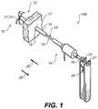
- FIG. 1is an isometric view of a medical system including a closure device according to an example embodiment
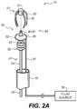
- FIG. 2Ais a partially exploded schematic view of a portion of closure device of an example embodiment
- FIG. 2Bis a schematic sectional view of a portion of the closure device of FIG. 2A ;
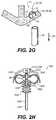
- FIGS. 2C to 2Gis a schematic representation of a sequence of operations employing the closure device of FIG. 2A according to an example embodiment
- FIG. 2His a schematic detailed view of a portion of a closure device according to another example embodiment.
- FIG. 3Ais a schematic sectional view of a device according to an example embodiment, the device including a closure unit, an intermediate member and an inflatable member in a retracted state;
- FIG. 3Bis a schematic sectional view of the device of FIG. 3A with the inflatable member in an extended state;
- FIG. 3Cis an isometric view of the device of FIG. 3A with the inflatable member in an extended state
- FIG. 4is an isometric view of a clip employed in an example embodiment
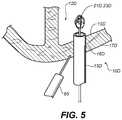
- FIG. 5is a cross-sectional view of a closure device as per another example embodiment
- FIGS. 6A, 6B and 6Care schematic representations of various stages of a closing of a first opening in an anatomical cavity as per another example embodiment
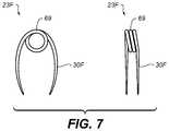
- FIG. 7includes front and side views of a clip employed in another example embodiment
- FIGS. 8A, 8B, 8C, 8D and 8Eare schematic representations of various stages of a closing of a first opening in an anatomical cavity as per another example embodiment.
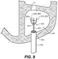
- FIG. 9is schematic view of a closure device according to an example embodiment that is employed to close an opening in an anatomical cavity that includes a plurality of openings.
- a medical system 100 including a closure device 10is inserted into an anatomical cavity 12 such a cavity in the heart via catheter 14 .
- a tubular member 15is shown inserted into a first opening 16 that leads through a tissue wall 17 to anatomical cavity 12 .
- first opening 16has been formed in tissue wall 17 with a perforating member or instrument (not shown).
- perforating memberscan be used to form first opening 16 in tissue wall 17 .
- puncturing memberssuch as trocars are commonly employed to form openings in tissue walls.
- other forms of perforating methodsincluding cutting, ablation, and irradiation techniques can be employed by various embodiments.
- Catheter 14employs a seal (not shown) allowing insertion and removal of various instruments and devices without much blood loss. This is well known in the art of minimally invasive surgery.
- tubular member 15allows for the passage of closure device 10 through first opening 16 into anatomical cavity 12 .
- closure device 10includes an elongated member 20 .
- elongated member 20includes a closure unit 21 and a rod member 24 sized for providing closure unit 21 into anatomical cavity 12 via passage through tubular member 15 along a first direction 25 .
- Both rod member 24 and tubular member 15have respective flanges 27 and 18 allowing a pulling tool 26 to exert a significant pulling force on rod member 24 relative to tubular member 15 .
- pulling tool 26is arranged to pull rod member 24 through tubular member 15 along a second direction 28 that is opposite to first direction 25 in a manner similar to that taught in commonly assigned U.S. patent application Ser. No. 11/436,585 which is herein incorporate by reference.
- Pulling tool 26may be made of plastic or metal, plastic being preferred if tool is to be disposable.
- Rod member 24 and tubular member 15are preferably made of stainless steel.
- closure unit 21is adapted for constricting a portion of first opening 16 .
- closure unit 21includes clip 23 .
- closure unit 21may include alternate and/or additional elements or members.
- FIG. 2Ais schematic a partially exploded view of a portion of closure device 10 .
- FIG. 2Bis a schematic sectional view of a portion of the closure device 10 of FIG. 2A .
- FIGS. 2C to 2Gshow a sequence of operations employing the closure device 10 of FIG. 2A as per a method according to an example embodiment.
- clip 23includes various piercing elements 30 arranged to engage a surface of anatomical cavity 12 . (i.e., not shown in FIG. 2A ).
- each piercing element 30is arranged to pierce a portion of tissue wall 17 (not shown in FIG. 2A ) that defines a portion of anatomical cavity 12 .
- four (4) piercing elements 30are employed, although it is understood that other suitable number of piercing elements 30 can be employed in other example embodiments.
- the number of piercing elements 30can vary in accordance with a particular closure method that is employed by a given example embodiment.
- each of the at least two piercing elements 30is employed to pinch at least a portion of the interior tissue surface within the anatomical cavity 12 including a port of the first opening 16 .
- each of the at least two piercing elements 30is employed to pinch at least a portion of tissue wall 17 that includes first opening 16 .
- at least one piercing element 30can be employed to pierce a portion of the interior tissue surface within the anatomical cavity 12 proximate a port of the first opening 16 .
- each piercing element 30is made of Nitinol, a highly flexible Nickel Titanium alloy well known in the art of medical devices. Since the elastic range of Nitinol is about ten times larger than steel, clip 23 can be made formed into a sufficiently small initial configuration adapted passage through tubular member 15 . It is noted that in some example embodiments, the initial configuration can accommodate minor amounts of interference with the interior surface of tubular member 15 since clip 23 typically includes sufficient compliance to accommodate this interference. Care should however be maintained to reduce the generation of debris that may arise from frictional effects generated during the passage of clip 23 through tubular member 15 .
- expansion forcescan be applied to clip 23 when it is position within anatomical cavity 12 to cause clip 23 to assume a configuration suitable for gripping a portion of tissue wall 17 over an area significantly larger than the area of a port of first opening 16 .
- clip 23tries to return to its natural (relaxed) shape, which covers a significantly smaller area, pulling the tissue with it and forming an instant haemostatic seal.
- closure device 10includes an inflatable member 32 positioned between clip 23 and rod member 24 as best seen in FIG. 2A and FIG. 2B .
- Inflatable member 32can include various suitable expansion members including bladders and balloons by way of non-limiting example.
- inflatable member 32is coupled to a fluid source 36 via conduit 34 .
- conduit 34passes through tubular member 15 .
- conduit 34is shown as a separate member from rod member 24 .
- conduit 34 and rod member 24can be integrated into a single assembly.
- conduit 34can take the form of a passageway within rod member 24 .
- fluid supply 36is selectively controllable to provide a suitable pressurized fluid to inflatable member 32 via conduit 34 .
- a suitable fluidsuch as a saline solution that is commonly used in the art may be used to inflate inflatable member 32 .
- inflatable member 32includes a flexible membrane 38 that is adapted from moving between a retracted position to an extended position in accordance the selective control of fluid source 36 .
- the contracted positioncorresponds to deflated state of inflatable member 32 whereas the extended position corresponds to an inflated state of inflatable member 32 . It is understood that these positions can be adjusted to suit in accordance with the selective application of fluid that is provided to inflatable member 32 .
- inflatable member 32is sized too large to be advanced through first opening 16 in the extended position.
- Fluid source 36can include by way of non-limiting example, a supply of pressurized fluid, various valves and various regulators adapted for selectively supplying fluid with a desired characteristic such a particular pressure value.
- inflatable member 32is positioned between the piercing elements 30 of clip 23 .
- Flexible membrane 38is shown positioned in the extended position in FIG. 2B . This positioning of flexible membrane 38 has caused a spacing between piercing elements 30 to increase. As shown in FIG.
- inflatable member 32is positioned between piercing elements 30 to help reduce occurrences of a pointed portion 33 of each piercing element 30 from extending beyond a surface 39 of flexible membrane 38 when flexible membrane 38 is in the extended position. This positioning can be employed to help reduce occurrences in which piercing elements 30 inadvertently engage a surface or other structure in anatomical cavity 12 .
- inflatable member 32is annular in form and is positioned proximate to a coupling 40 of elongated member 20 .
- coupling 40includes a threaded end 41 that is provided for threaded attachment with a hub 31 of clip 23 . Hub 31 is arranged to physically coupling each of piercing elements 30 together.
- coupling 40allows clip 23 to be releasably coupled to elongated member 20 . It is understood that coupling 40 is not limited to threaded couplings and other suitable couplings can be employed in other example embodiments.
- elongated member 20includes a bending portion 50 .
- bending portion 50is positioned between a distal portion 44 of elongated member 20 that includes at least clip 23 and inflatable member 32 and a proximal portion 42 of elongated member 20 that includes at least rod member 24 .
- distal portion 44includes an instrument adapted for modifying a portion of an interior tissue surface within the anatomical cavity 12 .
- Bending portion 50allows for a relative articulated movement between distal portion 44 and proximal portion 42 .
- Bending portion 50allows for a relative swinging movement between distal portion 44 and proximal portion 42 .
- Bending portion 50allows distal portion 44 to be reoriented relative to proximal portion 42 .
- bending portion 50can include various bending members such as a jointed or flexible hinge member, an articulated joint that includes various segments united by joints or flexures or a flexible coupling that includes a discrete or an infinite number of bending points.
- bending portion 50is employed to pivotally couple distal portion 44 to proximal portion 42 .
- bending portion 50allows for threaded end 41 to rotate about its axis.
- bending portion 50enables elongated member 20 to have both torsional and axial stiffness, while allowing for rotation as described above.
- bending portion 50allows distal portion 44 to pivot relatively to proximal portion 42 in three dimensional space.
- bending portion 50is an unconstrained bending portion adapted to freely bend.
- bending portion 50is sized for passage through tubular member 15 into anatomical cavity 12 .
- FIG. 2Cshows a positioning of clip 23 and inflatable member 32 within anatomical cavity 12 after a passage through tubular member 15 positioned in first opening 16 in tissue wall 17 .
- flexible membrane 38is positioned in the retracted position during the passage of inflatable member 32 through tubular member 15 .
- rod member 24was advanced along first direction 25 to position these members within anatomical cavity 12 .
- fluid source 36is selectively controlled to cause inflatable member 32 to inflate and cause the flexible membrane 38 to move to its extended position.
- the movement of flexible membrane 38in turn increases a spacing between the piercing elements 30 of clip 23 .
- the movement of flexible membrane 38imparts spring energy in piercing elements 30 .
- inflatable member 32is employed to cause clip 23 to expand to a position referred to as a deployment-ready position.
- anatomical cavity 12is defined by various interior tissue surfaces.
- first opening 16extends through tissue wall 17 along a path having a direction that is skewed relative to interior tissue surface 13 within anatomical cavity 12 .
- first opening 16extends through tissue wall 17 along a path having a direction that obliquely intersects a portion of interior tissue surface 13 .
- interior tissue surface 13includes a port 19 of first opening 16 . It is noted that that interior tissue surface 13 can be skewed relative to opening 16 in three dimensional space.
- interior tissue surface 13 having skewed orientations relative to first opening 16can create difficulties in employing a closure device, especially one that employs a clip.
- clip 23 as oriented in FIG. 2Dwere to be brought into contact with obliquely oriented interior tissue surface 13 , not all of the piercing elements 30 would be correctly positioned for proper engagement with interior tissue surface 13 .
- fluid supply 36be operated to cause a deflation of inflatable member 30 to reduce a spacing between the piercing elements 30 to constrict a portion of first opening 16 .
- each of the piercing elements 30is not properly positioned for the required engagement with interior tissue surface 13 , the effectiveness of the pinching action provided by piercing elements 30 may become compromised. It is understood that the amount of skew associated with a surface such as interior tissue surface 13 can vary from patient to patient or from medical procedure to medical procedure. In some cases, surface orientations having little or substantially no skew may be encountered while in other cases, surface orientations having pronounced skew (i.e. acute angles) may be encountered.
- closure device 10includes an orientation control unit 60 which is also sized for insertion into anatomical cavity 12 via tubular member 15 positioned in first opening 16 .
- orientation control unit 60includes a contact surface arranged to contact interior tissue surface 13 .
- the contact surface of orientation control unit 60is provided by surface 39 of flexible membrane 38 .
- Surface 39is herein referred to as contact surface 39 .
- contact surface 39is provided when flexible membrane 38 is moved to its extended position.
- orientation control unit 60is operable for changing an orientation of distal portion 44 relative to proximal portion 42 .
- orientation control unit 60is operable for changing an orientation of distal portion 44 relative to proximal portion 42 upon establishing contact between contact surface 39 and interior tissue surface 13 .
- orientation control unit 60is operable to cause bending portion 50 to bend.
- the expanded clip 23 and contact surface 39are retracted by rod member 24 which is advanced along second direction 28 as shown in FIG. 2E .
- the retraction of rod member 24 along second direction 28causes a portion of contact surface 39 to come into contact with interior tissue surface 13 .
- orientation control unit 60causes a change in the orientation of distal portion 44 relative to proximal portion 42 .
- a retraction of tubular member 15 along second direction 28is also made.
- tubular member 15is retracted at least enough to allow contact surface 39 to contact interior tissue surface 13 . It is noted that for clarity, a portion of tubular member 15 has been sectioned to show bending portion 50 in FIGS. 2E and 2F .
- orientation control unit 60is operable for reducing an angular deviation of distal portion 44 from an axis (not shown) positioned normal to a point on interior tissue surface 13 .
- orientation control unit 60is operable for defining an orientation of interior tissue surface 13 and aligning distal portion 44 in accordance with the defined orientation.
- orientation control unit 60is operable for defining an orientation of interior tissue surface 13 simultaneously with the aligning of distal portion 44 in accordance with the defined orientation.
- orientation control unit 60forms a portion of a self-aligning mechanism employed to align distal portion 44 to interior tissue surface 13 .
- the self aligning mechanismincludes bending portion 50 .
- orientation control unit 60is not limited to the illustrated embodiments. Those skilled in the art will quickly understand that orientation control unit 60 can include other forms of elements operable for defining an orientation of a skewed interior tissue surface 13 and orienting distal portion 44 in accordance with the defined orientation.
- orientation control units 60 employed in various embodimentscan include actively controlled elements including suitable drives and actuators as well as passive elements that are each positionable within an anatomical cavity to define an orientation of a skewed interior tissue surface 13 and/or to orient distal portion 44 in accordance with the defined orientation.
- contact surface 39can include a contact surface other than a surface provided by inflatable member 32 .
- clip 23when the clip 23 has been correctly positioned by orientation control unit 60 , clip 23 is deployed into a portion of tissue wall 17 by further retracting rod member 24 along second direction 28 and by operating fluid source 36 to deflate inflatable member 32 .
- Deflating inflatable member 32causes flexible membrane 38 to move towards its retracted position and reduce a spacing between the piercing elements 30 .
- clip 23engages a plurality of regions of interior tissue surface 13 and applies a pinching force suitable for drawing the plurality of regions together, each of the regions being located proximate to port 19 .
- clip 23will deploy in a manner where each of the piercing elements 30 will apply pinching forces to a portion the tissue wall 17 (i.e. including a portion of interior tissue surface 13 ) as the piercing elements are drawn into tissue wall 17 to constrict a portion of first opening 16 . Since orientation control unit 60 has oriented clip 23 substantially normal to interior tissue surface 13 , a robust anchoring of the clip 23 into the tissue wall 17 can be advantageously achieved.
- the combination of retracting rod member 24 along second direction 28 and the deflation of inflatable member 32 to deploy piercing elements 30 into tissue wall 17may require a lateral repositioning of rod member 24 and bending portion 50 within tubular member 15 to fully achieve full penetration of each of the piercing elements 30 .
- one or more of rod member 24 , bending portion 50 and tubular member 15are appropriately sized to provide sufficient clearance to accommodate a lateral repositioning of rod member 24 and bending portion 50 . This clearance can reduce occurrences of undesired moments being applied to clip 23 during its deployment into tissue wall 17 .
- a spacing between the orientation control unit 60 and the bending portion 50is predetermined to position a bending point of bending portion 50 proximate to interior tissue surface 13 when orientation control unit 60 is operated to change the orientation of distal portion 44 relative to proximal portion 42 .
- bending portion 50is positioned in anatomical cavity 12 rather than first opening 16 when orientation control unit 60 is operated to change the orientation of distal portion 44 relative to proximal portion 42 .
- a spacing between the orientation control unit 60 and the bending portion 50is predetermined to position a bending point of bending portion 50 in anatomical cavity 12 when orientation control unit 60 is operated to change the orientation of distal portion 44 relative to proximal portion 42 .
- bending portion 50 or a bending point of bending portion 50is positioned between piercing elements 30 .
- bending portion 50includes a virtual pivot point about which an orientation of distal portion 44 can change with respect to proximal portion 42 .
- bending portionincludes a virtual pivot point that is positioned between piercing elements 30 .
- tubular member 15has been retracted from first opening 16 to position an end portion of tubular member 15 away from a portion of first opening 16 as the piercing elements 30 are deployed into tissue wall 17 .
- the retraction of tubular member 15allows a portion of first opening 16 to contract and decrease in diameter under the pinching action of piercing elements 30 thereby constricting the portion of first opening 16 .
- the pinching forces applied by clip 23are able to affect the decrease of diameter of the first opening 16 in tissue wall 17 as clip 23 returns close to its natural shape. It is noted that some degree of inherent spring energy can be maintained within clip 23 .
- inflatable member 32has been fully deflated, clip 23 will be fully deployed into tissue wall 17 .
- inflatable member 32can be re-inflated and rod member 24 can be repositioned to un-deploy clip 23 and allow the operating physician another opportunity to close first opening 16 .
- rod member 24can be rotated to disengage threaded end 41 from the hub 31 of clip 23 , and a remaining portion of elongated member 20 may be pulled out from the constricted portion of first opening 16 to allow for a further constriction of first opening 16 .
- the elastic compliance provided by the piercing elements 30 of clip 23allow for the removal of a remaining portion of elongated member 20 from the constricted portion of first opening 16 .
- the extraction of rod member 24is also accompanied by the extraction of inflatable member 32 and conduit 34 .
- the extraction of rod member 24also causes the extraction of inflatable member 32 and conduit 34 .
- At least one of inflatable member 32 and conduit 34is extracted separately from rod member 24 .
- inflatable member 32can be securely affixed to conduit 34 with a coupling that provides sufficient strength to allow an extraction of conduit 34 to also result in an extraction of inflatable member 32 .
- the deflated state of inflatable member 32is predetermined to be adequately sized to allow for passage through the constricted portion of first opening 16 .
- the elastic compliance provided by the piercing elements 30 of clip 23is predetermined to allow for the extraction of deflated inflatable member 32 .
- inflatable member 32is not extracted from the anatomical cavity 12 in this example embodiment. Rather both clip 23 and inflatable member 32 remain within anatomical cavity 12 after the remaining portion of elongated member 20 has been extracted.
- inflatable member 32is releasably coupled to each of rod member 24 and conduit 34 in a manner suitable for allowing inflatable member 32 to remain within anatomical cavity 12 upon their extraction.
- inflatable member 32can be slidably coupled to threaded end 41 .
- a flange 43shown in FIGS. 2A and 2B ) or other abutment can be incorporated to maintain a coupling between inflatable member 32 and threaded end 41 when rod member 15 is advanced along first direction 25 .
- FIG. 2Hshows a schematic detailed view of a portion of a closure device 10 A according to another example embodiment.
- a conduit 34 Ais provided integrally within a rod member 24 A, a bending portion 50 A and a threaded end 41 A.
- Ports 45provide fluid communication between conduit 34 A and inflatable member 32 A which includes a flexible membrane 38 A that is selectively moveable between a retracted position and an extended position. Sealing portions 46 of inflatable member 32 A seal against threaded end 41 A.
- inflatable member 32 Ais captured between flange 43 A and a closure unit 21 A.
- Closure unit 21 Aincludes a clip 23 A which includes a plurality of piercing elements 30 A.
- Clip 23 Ais releasably coupled to threaded end 41 A via a threaded coupling.
- threaded end 41 AWhen threaded end 41 A is unscrewed from clip 23 A, threaded end 41 A can be retracted from inflatable member 32 A which can be left behind in an anatomical cavity 12 .
- Other suitable couplingscan be employed to couple with clip 23 A in other example embodiments.
- Flexible membrane 38 Ais shown in the extended position under the influence of a fluid (not shown) provided through conduit 34 A.
- inflatable member 32is shown positioned between clip 23 and interior tissue surface 13 .
- the deployed piercing elements 30act to capture inflatable member 32 between clip 23 and interior tissue surface 13 .
- inflatable member 32can be coupled with hub 31 .
- closure device 10includes a constricting unit 55 (i.e. clip 23 ) and an occluding member 56 (i.e. inflatable member 32 ), both of which are employed to close first opening 16 from within anatomical cavity 12 .
- constricting unit 55i.e.
- occluding member 56i.e. inflatable member 32
- a portion of flexible membrane 38is employed to block the constricted portion of first opening 16 .
- a portion of flexible membrane 38is employed to block the constricted portion of first opening 16 when flexible membrane 38 is positioned in the retracted position.
- inflatable member 32is employed as one example of an occluding member 56 that is positioned to additionally block the constricted portion of first opening 16 to advantageously enhance the efficacy of the closure of first opening 16 .
- an occluding member 56 including an absorbent materialis employed.
- an occluding member 56 including an element adapted for providing a mendicant to the constricted portion of first opening 16is employed.
- an occluding member 56 including Dacron® or other material that has sealing capabilitiesis employed.
- an occluding member 56includes a bio-absorbable material. It is understood the constricting units 55 and occluding members 56 are not limited to clip 23 and inflatable member 32 respectively in various other embodiments. Without limitation, other suitable constricting members 55 and occluding members 56 can be employed in other embodiments.
- FIGS. 3A, 3B and 3Care various views of a portion of a closure device 10 B that is insertable into anatomical cavity 12 B via a tubular member 15 B positioned in a first opening 16 B that leads to anatomical cavity 12 B.
- closure device 10 Bincludes a closure unit 21 B that is operable to constrict a portion of first opening 16 B provided in tissue wall 17 B.
- closure unit 21 Bincludes a clip 23 B. Clip 23 B and an inflatable member 32 B are operated to constrict a portion of the first opening 16 B in a manner similar to other example embodiments described in the present specification.
- closure unit 21 Bis operable to constrict a portion of the first opening 16 B that includes a portion of an interior tissue surface 13 B of the anatomical cavity 12 B that includes a port 19 B of the opening 16 B.
- Clip 23 Bincludes a plurality of piercing elements 30 B coupled together by a hub 31 B. Hub 31 B is releasably coupled via a threaded coupling to an elongated member 20 B arranged to insert closure unit 21 B through first opening 16 B into anatomical cavity 12 B.
- FIG. 3Ais a schematic sectional view of inflatable member 32 B in a deflated or retracted state and FIG. 3B shows a sectional view of inflatable member 32 B in an inflated or extended state.
- FIG. 3Cis an isometric view of inflatable member 32 B in an extended state.
- inflatable member 32 Binclude a flexible membrane 38 B that is selectively moveable between a retracted position (i.e., shown in FIG. 3A ) and an extended position (i.e., shown in FIG. 3B ) under a selective application of a fluid (not shown).
- Flexible membrane 38 Bis arranged to adjust a spacing between the piercing elements 30 B of clip 23 B in a manner similar to that described in other example embodiments.
- closure device 10 Bincludes an intermediate member 35 that is positionable between the closure unit 21 B (i.e. clip 23 B) and interior tissue surface 13 B.
- intermediate member 35includes a plurality of pads 37 that are positionable between clip 23 B and interior tissue surface 13 B.
- at least one of the piercing elements 30 Bis arranged to pierce through a pad 37 .
- at least one of the piercing elements 30 Bis arranged to pierce through a pad 37 into interior tissue surface 13 B.
- pads 37are pierced prior to the deployment of piercing elements 30 B into interior tissue surface 13 B to constrict a portion of opening 16 B. In some example embodiments, pads 37 are pierced during the deployment of piercing elements 30 B into interior tissue surface 13 B to constrict a portion of opening 16 B.
- each of the pads 35corresponds to a respective one of the piercing elements 30 B.
- each pad 35is positioned in a pocket 47 provided in inflatable member 32 B to locate each pad 37 relative to a respective one of piercing elements 30 B in this example embodiment.
- Other example embodimentsmay include other arrangements between an intermediate member 35 and a piercing member 30 B.
- a single pad 37can be positioned to be pierced by at least two of piercing elements 30 B.
- An annular shaped intermediate member 35can be positioned to be pierced by all of the piercing elements 30 B.
- each of the pads 37 of intermediate member 35is positioned around a perimeter of flexible membrane 38 B.
- each pad 37 of intermediate member 35is positioned to be pierced by a piercing element 30 B when the flexible membrane 38 B is moved to an extended position.
- inflatable member 32 Bprovides the intermediate member 35 .
- intermediate member 35includes an inflatable portion (i.e., flexible membrane 38 B) and a non-inflatable portion (i.e., pads 37 ).
- the non-inflatable portionis positionable to a location where it can be pierced by a piercing element 30 B.
- pads 37are employed to reduce occurrences in which pointed portions 33 B of the piercing elements 30 B can catch or damage anatomical features or structures in anatomical cavity 12 B prior to the deployment of piercing elements 30 B into interior tissue surface 13 B.
- intermediate member 35is employed as a reinforcement member to distribute the puncturing pressure as piercing elements 30 B are deployed into interior tissue surface 13 B. This is particularly beneficial when the integrity of the pierced underlying tissue has been compromised from factors such as disease or advanced age.
- intermediate member 35acts as a pledget.
- intermediate member 35is employed to promote healing.
- intermediate member 35can include one or more of an absorbent material, a bio-absorbable material, and an elastic material.
- intermediate member 35can be employed to apply a mendicant to interior tissue surface 13 B.
- each of closure unit 21 B and intermediate member 35are releasably coupled to the elongated member 20 B and remain within anatomical cavity 12 B in a manner similar to that described in other example embodiments. It is understood that closure unit 21 B is not restricted to constricting units.
- closure unit 21 Bcan include an occluding member or blocking member arranged to block a portion of first opening 16 B from within anatomical cavity 12 B.
- a closure unit 21 B and an intermediate member 35are inserted into anatomical cavity 12 B and positioned proximate to interior tissue surface 13 B of anatomical cavity 12 B.
- At least one piercing element 30 Bis also provided to pierce intermediate member 35 .
- at least one piercing element 30 Bcan be employed to anchor intermediate member 35 to interior tissue surface 13 B.
- at least one piercing element 35 Bcan be employed to anchor closure unit 21 B to interior tissue surface 13 B.
- FIG. 4is an isometric view of a clip 23 C employed in an example embodiment.
- Clip 23 Cincludes a hub 31 C and a plurality of piercing elements 30 C.
- hub 31 Cincludes a bio-absorbable material, such as a synthetic co-polymer.
- hub 31 Cis formed around the piercing elements 30 C.
- hub 31 Cincludes a plurality of openings adapted for accepting the protrusion of piercing elements 30 C therethrough.
- hub 31 Cis releasably and reversibly coupled to an elongated member 20 (not shown) which is employed for the deployment and possible extraction of clip 23 C from a tissue wall 17 of an anatomical cavity 12 .
- hub 31 CWhen piercing elements 30 C are embedded into tissue as per various example embodiments, hub 31 C will serve to exert force on the piercing elements 30 C to drive them into the tissue. Once clip 23 C has been deployed and haemostasis is achieved, hub 31 C will be absorbed into the tissue, leaving only the piercing elements 30 C remaining in the tissue. This feature is advantageous in reducing the overall footprint of the remaining components in the tissue, thereby reducing obstructions that can impact potential future procedures at the same or surrounding location.
- FIG. 5is a cross-sectional drawing of a closure device 10 D as per another example embodiment.
- tubular member 15 Dis utilized to deliver a closure unit 21 D to an interior tissue surface 13 D of an anatomical cavity 12 D in manner similar to that described in other example embodiments.
- closure unit 21 Dincludes a clip 23 D arranged to constrict a portion of first opening 16 D.
- closure unit 21 Dmay include an occluding member.
- applicator 65is used to deliver an injection of a material (e.g. collagen) that acts to locally swell or expand the cells around the first opening 16 D in the tissue wall 17 D.
- a materiale.g. collagen
- This injectioncan occur slightly before or during the delivery of closure unit 21 D.
- Another variant of this example embodimentcan use a bio-adhesive suitable for cardiovascular applications that is applied into the closure in tissue wall 17 D after tubular member 15 D has been removed to help in sealing first opening 16 D.
- the use of this system in conjunction with closure methods described in other example embodimentscan provide a more effective seal during the closure procedure with resulting improvements in short and long-term haemostasis.
- FIGS. 6A, 6B and 6Care schematic representations of various stages of a closing of a first opening 16 E in an anatomical cavity 12 E as per another example embodiment.
- tubular member 15 Eis utilized to deliver a closure unit 21 E through first opening 16 E that is provided in a tissue wall 17 E that surrounds a portion of anatomical cavity 12 E.
- closure unit 21 Eincludes a clip 23 E that is arranged to constrict a portion of first opening 16 E in a manner similar to that described in other example embodiments.
- Clip 23 Eis coupled to elongated member 20 E.
- clip 23 Eincludes a plurality of piercing elements 30 E that are sized to extend beyond an outer surface of tissue wall 17 E into which they are to be deployed.
- the piercing elements 30 Eare arranged to pierce through tissue wall 17 E.
- FIG. 6Bshows that clip 23 E has been fully deployed into tissue wall 17 E, and a portion of first opening 16 E has been constricted after tubular member 15 E has been retracted from first opening 16 E.
- a capping member 67positioned outside of tissue wall 17 E in proximity to the portions of piercing elements 30 E which protrude from tissue wall 17 E.
- Capping member 67includes various elements (not shown) adapted for coupling with the protruding portions of piercing elements 30 E.
- Capping member 67additionally secures clip 23 E to tissue wall 17 E thereby further promoting closure of opening 16 E and reducing occurrences of clip 23 E losing its purchase with tissue wall 17 E.
- the elements of capping member 67 that are adapted for coupling with the protruding portions of piercing elements 30 Ecan take various forms.
- FIG. 7includes front and side views of a clip 23 F employed in another example embodiment.
- Clip 23 Fincludes a plurality of piercing elements 30 F that are coupled together by a bias member 69 (e.g. a torsional spring) that acts to enhance the elastic restorative force of the clip 23 F.
- a bias member 69e.g. a torsional spring
- FIGS. 8A, 8B, 8C, 8D and 8Einclude schematic representations of various stages of a closing of a first opening 16 G in an anatomical cavity 12 G as per another example embodiment.
- tubular member 15 Gis utilized to deliver a clip 23 G through first opening 16 G that is provided in a tissue wall 17 G that surrounds a portion of anatomical cavity 12 G.
- clip 23 Gis releasably coupled to an elongated member 20 G arranged to advance clip 23 G through tubular member 15 G.
- deployment arms 70capture the piercing elements 30 G of clip 23 G in a manner similar to that taught in commonly assigned U.S. patent application Ser. No. 11/436,585.
- a pad 72is coupled to deployment arms 70 in a manner that causes pad 72 to extend beyond the ends of piercing elements 30 G that are captured by the ends of deployment arms 70 .
- pad 72is elastic in nature and is stretched from an initial state to a configuration suitable for coupling with deployment arms 70 .
- pad 72can be coupled to deployment arms 70 by various methods including the use of adhesives or mechanical fastening systems.
- Pad 72can be coupled to deployment arms 70 with a fastening system that breaks apart under the application of a predetermined force.
- deployment arms 70can also position pad 72 in a retracted position suitable for passage through tubular member 15 G.
- pad 72includes an absorbent material.
- pad 72is coupled to clip 23 G.
- Deployment arms 70have been operated to outwardly extend the piercing elements 30 E thereby imparting spring or potential energy into piercing elements 30 G in FIG. 8B .
- Pad 72is also shown in an extended position that also results from this operation of deployment arms 70 .
- elongated member 20 Gis employed to exert a force on clip 23 G to bring piercing elements 30 G through pad 72 and into tissue wall 17 G.
- deployment arms 70are retracted while pad 72 is fixed in a larger stretched size due to the fixation by clip 23 G into tissue wall 17 G.
- pad 72is an intermediate member positioned between clip 23 G and tissue wall 17 G.
- FIG. 8Dshows the constricted first opening 16 G after tubing member 15 G has been retracted from first opening 16 G. Due to the retraction of tubing member 15 G, first opening 16 G has been constricted due to the elastic restorative forces of clip 23 G. The elastic nature of pad 17 has caused the perimeter of pad 72 to decrease proportionately with the inward movement of piercing elements 30 G. Deployment arms 70 have been retracted into the tubular member 15 G and a portion of elongated member 20 G remains coupled with clip 23 G. This coupling allows clip 23 G to be disengaged from the tissue wall 17 G and redeployed if the closure of first opening 16 G is deemed unsatisfactory.
- FIG. 8Eshows the completely retracted elongated member 20 G after the closure has been verified for haemostasis.
- elongated member 20 Gis decoupled from clip 23 G, and is pulled through the first opening 16 G.
- the complete assembly of tubular member 15 G, elongated member 20 G and deployment arms 70can be removed from the patient.
- a first opening 16e.g., first openings 16 , 16 A, 16 B, etc.
- a closure device 10e.g., closure devices 10 , 10 A, 10 B, etc.
- an anatomical cavity 12e.g., anatomical cavities 12 , 12 A, 12 B, etc.
- a first opening 16is a naturally occurring opening.
- a first opening 16is formed by factors such as disease.
- a first opening 16is formed by factors such as trauma.
- a first opening 16is formed with the use of a perforating member or instrument.
- FIG. 9is a schematic representation of an anatomical cavity 12 H that include a plurality of openings including a first opening 16 H and second opening 11 .
- a closure device 10 His employed to close second opening 11 .
- Closure device 10 His inserted into anatomical cavity 12 H via a tubular member 15 H inserted into a first opening 16 H.
- closure device 10 Hincludes a closure unit 21 H that is operable to constrict a portion of second opening 11 .
- closure unit 21 Hincludes a clip 23 H and an inflatable member 32 H that are operated to constrict a portion of the second opening 11 in a manner similar to other example embodiments described in the present specification.
- clip 23 Bincludes a plurality of piercing elements 30 H coupled together by a hub 31 H.
- Hub 31 His releasably coupled to elongated member 20 H which is arranged to advance closure unit 21 H through first opening 16 H into anatomical cavity 12 H.
- the piercing elements 30 Hextend away from elongated member 20 H in this example embodiment. This allows piercing elements 30 H to be positioned for deployment into a surface of anatomical cavity 12 H that includes second opening 11 .
- Inflatable member 32 Hincludes a flexible membrane 38 H that is selectively moveable between a retracted position and an extended position.
- inflatable member 32 His employed to space piercing elements 30 H apart when clip 23 B is positioned within anatomical cavity 12 H.
- Elongated member 20 H and inflatable member 32 Hare further operated to deploy clip 23 H into tissue surrounding second opening 11 to constrict a portion of second opening 11 .
- first opening 16 Hcan also be closed by employing techniques various embodiments for closing a first opening 16 provided in this disclosure. Alternatively, other techniques may be employed to close first opening 16 H if so desired.
- closure device 10 Hcan include an orientation control unit 60 adapted for defining an orientation of a surface of anatomical cavity 12 H that includes second opening 11 .
- closure device 10 Hcan include an intermediate member 35 positioned between clip 23 H and a surface of anatomical cavity 12 H that includes second opening 11 , the intermediate member 35 arranged to be pierced by a piercing element 30 H of clip 23 H.
Landscapes
- Health & Medical Sciences (AREA)
- Surgery (AREA)
- Life Sciences & Earth Sciences (AREA)
- Biomedical Technology (AREA)
- Nuclear Medicine, Radiotherapy & Molecular Imaging (AREA)
- Engineering & Computer Science (AREA)
- Heart & Thoracic Surgery (AREA)
- Medical Informatics (AREA)
- Molecular Biology (AREA)
- Animal Behavior & Ethology (AREA)
- General Health & Medical Sciences (AREA)
- Public Health (AREA)
- Veterinary Medicine (AREA)
- Cardiology (AREA)
- Surgical Instruments (AREA)
Abstract
Description
Claims (19)
Priority Applications (1)
| Application Number | Priority Date | Filing Date | Title |
|---|---|---|---|
| US15/869,572US10603022B2 (en) | 2010-06-07 | 2018-01-12 | Closing openings in anatomical tissue |
Applications Claiming Priority (4)
| Application Number | Priority Date | Filing Date | Title |
|---|---|---|---|
| US35227710P | 2010-06-07 | 2010-06-07 | |
| US13/112,695US9050066B2 (en) | 2010-06-07 | 2011-05-20 | Closing openings in anatomical tissue |
| US14/694,521US9918706B2 (en) | 2010-06-07 | 2015-04-23 | Closing openings in anatomical tissue |
| US15/869,572US10603022B2 (en) | 2010-06-07 | 2018-01-12 | Closing openings in anatomical tissue |
Related Parent Applications (1)
| Application Number | Title | Priority Date | Filing Date |
|---|---|---|---|
| US14/694,521ContinuationUS9918706B2 (en) | 2010-06-07 | 2015-04-23 | Closing openings in anatomical tissue |
Publications (2)
| Publication Number | Publication Date |
|---|---|
| US20180132836A1 US20180132836A1 (en) | 2018-05-17 |
| US10603022B2true US10603022B2 (en) | 2020-03-31 |
Family
ID=45065039
Family Applications (3)
| Application Number | Title | Priority Date | Filing Date |
|---|---|---|---|
| US13/112,695Active2031-08-27US9050066B2 (en) | 2010-06-07 | 2011-05-20 | Closing openings in anatomical tissue |
| US14/694,521Active2032-03-02US9918706B2 (en) | 2010-06-07 | 2015-04-23 | Closing openings in anatomical tissue |
| US15/869,572Active2031-12-11US10603022B2 (en) | 2010-06-07 | 2018-01-12 | Closing openings in anatomical tissue |
Family Applications Before (2)
| Application Number | Title | Priority Date | Filing Date |
|---|---|---|---|
| US13/112,695Active2031-08-27US9050066B2 (en) | 2010-06-07 | 2011-05-20 | Closing openings in anatomical tissue |
| US14/694,521Active2032-03-02US9918706B2 (en) | 2010-06-07 | 2015-04-23 | Closing openings in anatomical tissue |
Country Status (1)
| Country | Link |
|---|---|
| US (3) | US9050066B2 (en) |
Families Citing this family (10)
| Publication number | Priority date | Publication date | Assignee | Title |
|---|---|---|---|---|
| US7749249B2 (en) | 2006-02-21 | 2010-07-06 | Kardium Inc. | Method and device for closing holes in tissue |
| US8449605B2 (en) | 2006-06-28 | 2013-05-28 | Kardium Inc. | Method for anchoring a mitral valve |
| US7837610B2 (en) | 2006-08-02 | 2010-11-23 | Kardium Inc. | System for improving diastolic dysfunction |
| US20090287304A1 (en) | 2008-05-13 | 2009-11-19 | Kardium Inc. | Medical Device for Constricting Tissue or a Bodily Orifice, for example a mitral valve |
| WO2011041571A2 (en) | 2009-10-01 | 2011-04-07 | Kardium Inc. | Medical device, kit and method for constricting tissue or a bodily orifice, for example, a mitral valve |
| US9050066B2 (en) | 2010-06-07 | 2015-06-09 | Kardium Inc. | Closing openings in anatomical tissue |
| US8940002B2 (en) | 2010-09-30 | 2015-01-27 | Kardium Inc. | Tissue anchor system |
| US9072511B2 (en) | 2011-03-25 | 2015-07-07 | Kardium Inc. | Medical kit for constricting tissue or a bodily orifice, for example, a mitral valve |
| US11304688B2 (en) | 2019-06-05 | 2022-04-19 | Maine Medical Center | Gastrocutaneous closure device |
| US20220257224A1 (en)* | 2021-02-12 | 2022-08-18 | St. Jude Medical, Cardiology Division, Inc. | Occluder medical device |
Citations (276)
| Publication number | Priority date | Publication date | Assignee | Title |
|---|---|---|---|---|
| US3132438A (en) | 1963-09-13 | 1964-05-12 | Clarence J Ward | Fish hook removal device |
| US4114202A (en) | 1977-01-28 | 1978-09-19 | Roy Henry A | Prosthetic valve assembly for use in cardiovascular surgery |
| US4164046A (en) | 1977-05-16 | 1979-08-14 | Cooley Denton | Valve prosthesis |
| US4240441A (en) | 1978-10-10 | 1980-12-23 | The United States Of America As Represented By The Secretary Of The Navy | Carotid thermodilution catheter |
| US4261342A (en) | 1978-10-26 | 1981-04-14 | Iker Aranguren Duo | Process for installing mitral valves in their anatomical space by attaching cords to an artificial stent |
| US4263680A (en) | 1978-04-12 | 1981-04-28 | Beiersdorf, Ag | Prosthetic closure devices to replace the valves in human hearts |
| US4490859A (en) | 1982-01-20 | 1985-01-01 | University Of Sheffield | Artificial heart valves |
| US4543090A (en) | 1983-10-31 | 1985-09-24 | Mccoy William C | Steerable and aimable catheter |
| US4794912A (en) | 1987-08-17 | 1989-01-03 | Welch Allyn, Inc. | Borescope or endoscope with fluid dynamic muscle |
| US4850957A (en) | 1988-01-11 | 1989-07-25 | American Biomed, Inc. | Atherectomy catheter |
| US4890612A (en) | 1987-02-17 | 1990-01-02 | Kensey Nash Corporation | Device for sealing percutaneous puncture in a vessel |
| US4890602A (en) | 1987-11-25 | 1990-01-02 | Hake Lawrence W | Endoscope construction with means for controlling rigidity and curvature of flexible endoscope tube |
| US4893613A (en) | 1987-11-25 | 1990-01-16 | Hake Lawrence W | Endoscope construction with means for controlling rigidity and curvature of flexible endoscope tube |
| US4921499A (en) | 1987-10-05 | 1990-05-01 | Ordev B.V. | Adjustable prosthesis |
| WO1990015582A1 (en) | 1989-06-19 | 1990-12-27 | Trout Hugh H Iii | Aortic graft and method for repairing aneurysm |
| US5021059A (en) | 1990-05-07 | 1991-06-04 | Kensey Nash Corporation | Plug device with pulley for sealing punctures in tissue and methods of use |
| US5047047A (en) | 1988-10-26 | 1991-09-10 | Inbae Yoon | Wound closing device |
| US5100418A (en) | 1987-05-14 | 1992-03-31 | Inbae Yoon | Suture tie device system and applicator therefor |
| US5104399A (en) | 1986-12-10 | 1992-04-14 | Endovascular Technologies, Inc. | Artificial graft and implantation method |
| US5122137A (en) | 1990-04-27 | 1992-06-16 | Boston Scientific Corporation | Temperature controlled rf coagulation |
| US5156609A (en) | 1989-12-26 | 1992-10-20 | Nakao Naomi L | Endoscopic stapling device and method |
| US5192314A (en) | 1991-12-12 | 1993-03-09 | Daskalakis Michael K | Synthetic intraventricular implants and method of inserting |
| US5242456A (en) | 1991-11-21 | 1993-09-07 | Kensey Nash Corporation | Apparatus and methods for clamping tissue and reflecting the same |
| US5258000A (en) | 1991-11-25 | 1993-11-02 | Cook Incorporated | Tissue aperture repair device |
| US5312435A (en) | 1993-05-17 | 1994-05-17 | Kensey Nash Corporation | Fail predictable, reinforced anchor for hemostatic puncture closure |
| US5320632A (en) | 1991-11-13 | 1994-06-14 | Harald Heidmueller | Surgical suturing apparatus |
| US5364408A (en) | 1992-09-04 | 1994-11-15 | Laurus Medical Corporation | Endoscopic suture system |
| US5366459A (en) | 1987-05-14 | 1994-11-22 | Inbae Yoon | Surgical clip and clip application procedures |
| US5366443A (en) | 1992-01-07 | 1994-11-22 | Thapliyal And Eggers Partners | Method and apparatus for advancing catheters through occluded body lumens |
| US5368601A (en) | 1992-04-30 | 1994-11-29 | Lasersurge, Inc. | Trocar wound closure device |
| US5374275A (en) | 1993-03-25 | 1994-12-20 | Synvasive Technology, Inc. | Surgical suturing device and method of use |
| US5423859A (en) | 1991-11-13 | 1995-06-13 | United States Surgical Corporation | Jet entangled suture yarn and method for making same |
| US5450860A (en) | 1993-08-31 | 1995-09-19 | W. L. Gore & Associates, Inc. | Device for tissue repair and method for employing same |
| US5454834A (en) | 1992-03-12 | 1995-10-03 | Richard Wolf Gmbh | Surgical suture material |
| US5478353A (en) | 1987-05-14 | 1995-12-26 | Yoon; Inbae | Suture tie device system and method for suturing anatomical tissue proximate an opening |
| US5507811A (en) | 1993-11-26 | 1996-04-16 | Nissho Corporation | Prosthetic device for atrial septal defect repair |
| US5531760A (en) | 1995-04-14 | 1996-07-02 | Alwafaie; Mohammed G. | Skin closure clip |
| US5593424A (en) | 1994-08-10 | 1997-01-14 | Segmed, Inc. | Apparatus and method for reducing and stabilizing the circumference of a vascular structure |
| US5645566A (en) | 1995-09-15 | 1997-07-08 | Sub Q Inc. | Apparatus and method for percutaneous sealing of blood vessel punctures |
| US5702421A (en) | 1995-01-11 | 1997-12-30 | Schneidt; Bernhard | Closure device for closing a vascular opening, such as patent ductus arteriosus |
| US5713896A (en) | 1991-11-01 | 1998-02-03 | Medical Scientific, Inc. | Impedance feedback electrosurgical system |
| US5716397A (en) | 1996-12-06 | 1998-02-10 | Medtronic, Inc. | Annuloplasty device with removable stiffening element |
| US5720726A (en) | 1992-12-30 | 1998-02-24 | Medtronic, Inc. | Balloon catheter having retention enhancements on the balloon |
| US5728114A (en) | 1994-08-24 | 1998-03-17 | Kensey Nash Corporation | Apparatus and methods of use for preventing blood seepage at a percutaneous puncture site |
| US5752965A (en) | 1996-10-21 | 1998-05-19 | Bio-Vascular, Inc. | Apparatus and method for producing a reinforced surgical fastener suture line |
| US5782861A (en) | 1996-12-23 | 1998-07-21 | Sub Q Inc. | Percutaneous hemostasis device |
| US5800495A (en) | 1997-03-27 | 1998-09-01 | Sulzer Intermedics Inc. | Endocardial lead assembly |
| US5824066A (en) | 1995-12-01 | 1998-10-20 | Medtronic, Inc. | Annuloplasty prosthesis |
| US5836990A (en) | 1997-09-19 | 1998-11-17 | Medtronic, Inc. | Method and apparatus for determining electrode/tissue contact |
| US5861005A (en) | 1997-02-11 | 1999-01-19 | X-Site, L.L.C. | Arterial stapling device |
| US5865791A (en) | 1995-06-07 | 1999-02-02 | E.P. Technologies Inc. | Atrial appendage stasis reduction procedure and devices |
| US5919207A (en) | 1998-06-02 | 1999-07-06 | Taheri; Syde A. | Percutaneous arterial closure with staples |
| US5961440A (en) | 1997-01-02 | 1999-10-05 | Myocor, Inc. | Heart wall tension reduction apparatus and method |
| US5964782A (en) | 1997-09-18 | 1999-10-12 | Scimed Life Systems, Inc. | Closure device and method |
| US5971994A (en) | 1997-07-16 | 1999-10-26 | Gebrueder Berchtold Gmbh | High frequency surgical instrument |
| US6001069A (en) | 1997-05-01 | 1999-12-14 | Ekos Corporation | Ultrasound catheter for providing a therapeutic effect to a vessel of a body |
| US6024096A (en) | 1998-05-01 | 2000-02-15 | Correstore Inc | Anterior segment ventricular restoration apparatus and method |
| US6074417A (en) | 1992-11-16 | 2000-06-13 | St. Jude Medical, Inc. | Total mitral heterologous bioprosthesis to be used in mitral or tricuspid heart replacement |
| US6074418A (en) | 1998-04-20 | 2000-06-13 | St. Jude Medical, Inc. | Driver tool for heart valve prosthesis fasteners |
| US6104944A (en) | 1997-11-17 | 2000-08-15 | Martinelli; Michael A. | System and method for navigating a multiple electrode catheter |
| US6113610A (en) | 1995-06-07 | 2000-09-05 | Medtronic, Inc. | Device and method for suturing wound |
| US6203554B1 (en) | 1999-11-23 | 2001-03-20 | William Roberts | Apparatus, kit and methods for puncture site closure |
| US6210432B1 (en) | 1999-06-29 | 2001-04-03 | Jan Otto Solem | Device and method for treatment of mitral insufficiency |
| US6221103B1 (en) | 1996-01-02 | 2001-04-24 | The University Of Cincinnati | Device and method for restructuring heart chamber geometry |
| US6221104B1 (en) | 1998-05-01 | 2001-04-24 | Cor Restore, Inc. | Anterior and interior segment cardiac restoration apparatus and method |
| US6241747B1 (en) | 1993-05-03 | 2001-06-05 | Quill Medical, Inc. | Barbed Bodily tissue connector |
| US20010003158A1 (en) | 1991-11-08 | 2001-06-07 | Kensey Nash Corporation | Hemostatic puncture closure system and method of use |
| US6248124B1 (en) | 1999-02-22 | 2001-06-19 | Tyco Healthcare Group | Arterial hole closure apparatus |
| US20010005787A1 (en) | 1997-06-27 | 2001-06-28 | Oz Mehmet C. | Method and apparatus for circulatory valve repair |
| US6258258B1 (en) | 1998-10-06 | 2001-07-10 | Exxon Research And Engineering Company | Process for treatment of petroleum acids with ammonia |
| US20010018611A1 (en) | 1999-06-30 | 2001-08-30 | Solem Jan Otto | Method and device for treatment of mitral insufficiency |
| US20010020126A1 (en) | 1996-10-28 | 2001-09-06 | David K. Swanson | Systems and methods for visualizing tissue during diagnostic or therapeutic procedures |
| US6287321B1 (en) | 1998-10-13 | 2001-09-11 | Embol-X, Inc. | Percutaneous filtration catheter for valve repair surgery |
| US6304769B1 (en) | 1997-10-16 | 2001-10-16 | The Regents Of The University Of California | Magnetically directable remote guidance systems, and methods of use thereof |
| US6306135B1 (en) | 1999-11-22 | 2001-10-23 | Alan G. Ellman | Forehead lift suction probe |
| WO2001078625A1 (en) | 2000-04-13 | 2001-10-25 | Paolo Ferrazzi | Endoventricular device for the treatment and correction of cardiomyopathies |
| US20010041915A1 (en) | 1999-09-20 | 2001-11-15 | Roue Chad C. | Atrial septal defect closure catheter |
| US20010044568A1 (en) | 2000-01-31 | 2001-11-22 | Langberg Jonathan J. | Endoluminal ventricular retention |
| US6332864B1 (en) | 1997-01-02 | 2001-12-25 | Myocor, Inc. | Heart wall tension reduction apparatus |
| US20020013621A1 (en) | 2000-07-27 | 2002-01-31 | Robert Stobie | Heart valve holder for constricting the valve commissures and methods of use |
| US6346105B1 (en) | 1998-07-27 | 2002-02-12 | Quantum Cor Incorporated | Device for treating tissue and methods thereof |
| US6348064B1 (en) | 2000-09-01 | 2002-02-19 | Angiolink Corporation | Wound site management and wound closure device |
| US20020026092A1 (en) | 1998-05-01 | 2002-02-28 | Buckberg Gerald D. | Ventricular restoration patch |
| US6358277B1 (en) | 2000-06-21 | 2002-03-19 | The International Heart Institute Of Montana Foundation | Atrio-ventricular valvular device |
| US6358258B1 (en) | 1999-09-14 | 2002-03-19 | Abbott Laboratories | Device and method for performing end-to-side anastomosis |
| US6360749B1 (en) | 1998-10-09 | 2002-03-26 | Swaminathan Jayaraman | Modification of properties and geometry of heart tissue to influence heart function |
| US20020055775A1 (en) | 1999-01-26 | 2002-05-09 | Alain F. Carpentier | Flexible heart valve |
| US6391048B1 (en) | 2000-01-05 | 2002-05-21 | Integrated Vascular Systems, Inc. | Integrated vascular device with puncture site closure component and sealant and methods of use |
| US6391054B2 (en) | 1994-07-29 | 2002-05-21 | Edwards Lifesciences Corporation | Expandable annuloplasty ring |
| US6402680B2 (en) | 1998-07-29 | 2002-06-11 | Myocor, Inc. | Stress reduction apparatus and method |
| US6406420B1 (en) | 1997-01-02 | 2002-06-18 | Myocor, Inc. | Methods and devices for improving cardiac function in hearts |
| US6409760B1 (en) | 1998-03-05 | 2002-06-25 | University Of Cincinnati | Device and method for restructuring heart chamber geometry |
| US20020082621A1 (en) | 2000-09-22 | 2002-06-27 | Schurr Marc O. | Methods and devices for folding and securing tissue |
| US20020087173A1 (en) | 2000-12-28 | 2002-07-04 | Alferness Clifton A. | Mitral valve constricting device, system and method |
| US6416459B1 (en) | 1997-06-21 | 2002-07-09 | Acorn Cardiovascular Inc. | Bag for at least partially enveloping a heart |
| US20020111647A1 (en) | 1999-11-08 | 2002-08-15 | Khairkhahan Alexander K. | Adjustable left atrial appendage occlusion device |
| US6436052B1 (en) | 1997-03-31 | 2002-08-20 | Telecom Medical, Inc. | Method and system for sensing activity and measuring work performed by an individual |
| US20020115944A1 (en) | 1999-11-18 | 2002-08-22 | Emanuel Mendes | Systems and methods for monitoring wear and/or displacement of artificial joint members, vertebrae, segments of fractured bones and dental implants |
| US20020161394A1 (en) | 1997-09-26 | 2002-10-31 | Macoviak John A. | Aortic filter catheter |
| US6475223B1 (en) | 1997-08-29 | 2002-11-05 | Stereotaxis, Inc. | Method and apparatus for magnetically controlling motion direction of a mechanically pushed catheter |
| US20020169504A1 (en) | 2001-05-14 | 2002-11-14 | Alferness Clifton A. | Mitral valve therapy device, system and method |
| US20020169360A1 (en) | 1998-07-16 | 2002-11-14 | Cardiothoracic Systems, Inc., A California Corporation | Surgical procedures and devices for increasing cardiac output of the heart |
| US6485489B2 (en) | 1999-10-02 | 2002-11-26 | Quantum Cor, Inc. | Catheter system for repairing a mitral valve annulus |
| US20020183836A1 (en) | 2001-02-05 | 2002-12-05 | Liddicoat John R. | Apparatus and method for reducing mitral regurgitation |
| US20020183841A1 (en) | 2001-03-23 | 2002-12-05 | Cohn William E. | Method and apparatus for reducing mitral regurgitation |
| US20020188170A1 (en) | 2001-04-27 | 2002-12-12 | Santamore William P. | Prevention of myocardial infarction induced ventricular expansion and remodeling |
| WO2003015611A2 (en) | 2001-08-14 | 2003-02-27 | Viacor, Inc. | Method and apparatus for improving mitral valve function |
| US20030045896A1 (en) | 2001-02-28 | 2003-03-06 | Chase Medical, Lp | Method of using a ventricular restoration shaping apparatus |
| US20030050682A1 (en) | 1999-08-09 | 2003-03-13 | Sharkey Hugh R. | Device for improving cardiac function |
| US20030050693A1 (en) | 2001-09-10 | 2003-03-13 | Quijano Rodolfo C. | Minimally invasive delivery system for annuloplasty rings |
| US6537198B1 (en) | 2000-03-21 | 2003-03-25 | Myocor, Inc. | Splint assembly for improving cardiac function in hearts, and method for implanting the splint assembly |
| US6540670B1 (en) | 1999-03-19 | 2003-04-01 | Olympus Optical Co., Ltd. | Endoscope system |
| US20030069593A1 (en) | 2001-08-31 | 2003-04-10 | Tremulis William S. | Method and apparatus for valve repair |
| US20030069570A1 (en) | 1999-10-02 | 2003-04-10 | Witzel Thomas H. | Methods for repairing mitral valve annulus percutaneously |
| US6551312B2 (en) | 2001-03-09 | 2003-04-22 | Quantum Cor, Inc. | Wireless electrosurgical device and methods thereof |
| US20030078652A1 (en) | 2001-10-23 | 2003-04-24 | Sutherland Fraser W.H. | Heart valve prosthesis |
| US20030078671A1 (en) | 2001-04-27 | 2003-04-24 | Lesniak Jeanne M. | Prevention of myocardial infarction induced ventricular expansion and remodeling |
| US20030078465A1 (en) | 2001-10-16 | 2003-04-24 | Suresh Pai | Systems for heart treatment |
| US20030083742A1 (en) | 2000-02-02 | 2003-05-01 | Paul A. Spence | Heart valve repair apparatus and methods |
| US6569198B1 (en) | 2000-03-31 | 2003-05-27 | Richard A. Wilson | Mitral or tricuspid valve annuloplasty prosthetic device |
| US6569160B1 (en) | 2000-07-07 | 2003-05-27 | Biosense, Inc. | System and method for detecting electrode-tissue contact |
| US20030105520A1 (en) | 2001-12-05 | 2003-06-05 | Cardiac Dimensions, Inc. | Anchor and pull mitral valve device and method |
| US20030105384A1 (en) | 1999-08-09 | 2003-06-05 | Sharkey Hugh R. | Method of improving cardiac function using a porous membrane |
| US6575971B2 (en) | 2001-11-15 | 2003-06-10 | Quantum Cor, Inc. | Cardiac valve leaflet stapler device and methods thereof |
| US6589208B2 (en) | 2000-06-20 | 2003-07-08 | Applied Medical Resources Corporation | Self-deploying catheter assembly |
| US20030149333A1 (en) | 1996-10-02 | 2003-08-07 | Acorn Cardiovascular, Inc. | Cardiac reinforcement device |
| US20030167055A1 (en) | 2001-04-30 | 2003-09-04 | Kolata Ronald J. | Heart presentation device and method |
| WO2003077800A1 (en) | 2002-03-11 | 2003-09-25 | Cardiac Dimensions, Inc. | Device, assembly and method for mitral valve repair |
| US6626930B1 (en) | 1999-10-21 | 2003-09-30 | Edwards Lifesciences Corporation | Minimally invasive mitral valve repair method and apparatus |
| US6629988B2 (en) | 2001-08-28 | 2003-10-07 | Ethicon, Inc. | Composite staple for completing an anastomosis |
| US6632238B2 (en) | 2000-01-05 | 2003-10-14 | Integrated Vascular Systems, Inc. | Vascular sheath with puncture site closure apparatus and methods of use |
| US20030220667A1 (en) | 1998-11-06 | 2003-11-27 | Van Der Burg Erik J. | Method of containing embolic material in the left atrial appendage |
| US6662034B2 (en) | 2000-11-15 | 2003-12-09 | Stereotaxis, Inc. | Magnetically guidable electrophysiology catheter |
| US20030229395A1 (en) | 1998-06-16 | 2003-12-11 | Cardiac Concepts, Inc. | Mitral valve annuloplasty ring |
| US20040002626A1 (en) | 2001-07-16 | 2004-01-01 | Yair Feld | In-vivo method and device for improving diastolic function of the left ventricle |
| WO2004012629A1 (en) | 1999-08-09 | 2004-02-12 | Cardiokinetix, Inc. | A device for improving cardiac function |
| US20040034357A1 (en)* | 1999-08-03 | 2004-02-19 | University Of Massachusetts, A Massachusetts Corporation | Controlled release implantable devices |
| US20040054279A1 (en) | 2000-11-29 | 2004-03-18 | Peter Hanley | Catheter steering apparatus and method |
| US6723038B1 (en) | 2000-10-06 | 2004-04-20 | Myocor, Inc. | Methods and devices for improving mitral valve function |
| US20040078054A1 (en)* | 1998-06-05 | 2004-04-22 | Broncus Technologies, Inc. | Method for lung volume reduction |
| US6726716B2 (en) | 2001-08-24 | 2004-04-27 | Edwards Lifesciences Corporation | Self-molding annuloplasty ring |
| US6726704B1 (en) | 1998-05-29 | 2004-04-27 | By-Pass, Inc. | Advanced closure device |
| US6743241B2 (en) | 2002-03-01 | 2004-06-01 | Intellimed Surgical Solutions Llc | Laparoscopic port site fascial closure device |
| US6749622B2 (en) | 1999-09-13 | 2004-06-15 | Rex Medical, L.P. | Vascular closure |
| US20040127916A1 (en) | 1998-09-18 | 2004-07-01 | Aptus Endosystems, Inc. | Catheter-based fastener implantation apparatus and methods with implantation force resolution |
| US6760616B2 (en) | 2000-05-18 | 2004-07-06 | Nu Vasive, Inc. | Tissue discrimination and applications in medical procedures |
| US20040133273A1 (en) | 2002-11-15 | 2004-07-08 | Cox Daniel L. | Apparatuses and methods for heart valve repair |
| US20040133220A1 (en) | 2000-01-31 | 2004-07-08 | Randall Lashinski | Adjustable transluminal annuloplasty system |
| US20040138745A1 (en) | 2001-10-01 | 2004-07-15 | Ample Medical, Inc. | Methods and devices for heart valve treatments |
| US20040138529A1 (en) | 2003-01-15 | 2004-07-15 | Usgi Medical Corp. | Endoluminal tool deployment system |
| US20040158321A1 (en) | 2003-02-12 | 2004-08-12 | Cardiac Dimensions, Inc. | Method of implanting a mitral valve therapy device |
| US6780197B2 (en) | 2000-01-05 | 2004-08-24 | Integrated Vascular Systems, Inc. | Apparatus and methods for delivering a vascular closure device to a body lumen |
| US20040186566A1 (en) | 2003-03-18 | 2004-09-23 | Hindrichs Paul J. | Body tissue remodeling methods and apparatus |
| WO2004084746A2 (en) | 2003-03-26 | 2004-10-07 | Reitan Oeyvind M D | Device for treatment of an insufficiency of a heart valve |
| US20040215232A1 (en) | 2003-04-24 | 2004-10-28 | Belhe Kedar Ravindra | Device and method for positioning a closure device |
| US20040220593A1 (en) | 2003-05-01 | 2004-11-04 | Secant Medical, Llc | Restraining clip for mitral valve repair |
| WO2004100803A1 (en) | 2003-05-12 | 2004-11-25 | Cardiokinetix, Inc. | A system for improving cardiac function |
| US6824562B2 (en) | 2002-05-08 | 2004-11-30 | Cardiac Dimensions, Inc. | Body lumen device anchor, device and assembly |
| US20040243170A1 (en) | 2001-09-05 | 2004-12-02 | Mitta Suresh | Method and device for percutaneous surgical ventricular repair |
| US20040249408A1 (en) | 2001-09-05 | 2004-12-09 | Chase Medical, Lp | Method and device for endoscopic surgical ventricular repair |
| US20040249453A1 (en) | 2002-08-29 | 2004-12-09 | Cartledge Richard G. | Methods for controlling the internal circumference of an anatomic orifice or lumen |
| US20040260390A1 (en) | 2001-07-19 | 2004-12-23 | The Cleveland Clinic Foundation | Prosthetic valve and method for making same |
| US20040260393A1 (en) | 2000-09-20 | 2004-12-23 | Ample Medical, Inc. | Devices, systems, and methods for reshaping a heart valve annulus |
| US20040267358A1 (en) | 2001-12-11 | 2004-12-30 | Oyvind Reitan | Implant for treating an insufficiency of a heart valve |
| US20040267191A1 (en) | 2003-03-27 | 2004-12-30 | Cierra, Inc. | Methods and apparatus for treatment of patent foramen ovale |
| US20050004668A1 (en) | 2003-07-02 | 2005-01-06 | Flexcor, Inc. | Annuloplasty rings and methods for repairing cardiac valves |
| US6840957B2 (en) | 1999-10-21 | 2005-01-11 | Scimed Life Systems, Inc. | Implantable prosthetic valve |
| US20050015109A1 (en) | 2003-07-16 | 2005-01-20 | Samuel Lichtenstein | Methods and devices for altering blood flow through the left ventricle |
| US6855143B2 (en) | 1997-06-13 | 2005-02-15 | Arthrocare Corporation | Electrosurgical systems and methods for recanalization of occluded body lumens |
| US20050038509A1 (en) | 2003-08-14 | 2005-02-17 | Ashe Kassem Ali | Valve prosthesis including a prosthetic leaflet |
| US20050054938A1 (en) | 2003-07-29 | 2005-03-10 | Wehman Thomas C. | Method and apparatus including altimeter and accelerometers for determining work performed by an individual |
| US20050055089A1 (en) | 2000-09-20 | 2005-03-10 | Ample Medical, Inc. | Devices, systems, and methods for reshaping a heart valve annulus |
| US20050060030A1 (en) | 2000-01-31 | 2005-03-17 | Lashinski Randall T. | Remotely activated mitral annuloplasty system and methods |
| US20050064665A1 (en) | 2003-09-23 | 2005-03-24 | Han Chang Hun | Method for manufacturing a CMOS image sensor |
| US20050075727A1 (en) | 2001-10-29 | 2005-04-07 | Wheatley David John | Mitral valve prosthesis |
| US20050096647A1 (en) | 2003-09-12 | 2005-05-05 | Minnow Medical, Inc. | Selectable eccentric remodeling and/or ablation of atherosclerotic material |
| US20050096498A1 (en) | 2001-04-24 | 2005-05-05 | Houser Russell A. | Sizing and shaping device for treating congestive heart failure |
| US20050107871A1 (en) | 2003-03-30 | 2005-05-19 | Fidel Realyvasquez | Apparatus and methods for valve repair |
| US20050107723A1 (en) | 2003-02-15 | 2005-05-19 | Wehman Thomas C. | Methods and apparatus for determining work performed by an individual from measured physiological parameters |
| WO2005046520A2 (en) | 2003-11-07 | 2005-05-26 | Mayo Foundation For Medical Education And Research | Device and method for treating congestive heart failure |
| US6899674B2 (en) | 2002-03-07 | 2005-05-31 | Stm Medizintechnik Starnberg Gmbh | Endoscope shaft comprising a movable end portion |
| US20050125030A1 (en) | 2003-12-03 | 2005-06-09 | Forsberg Andrew T. | Vascular puncture seal anchor nest |
| US20050131441A1 (en) | 2003-12-16 | 2005-06-16 | Toshiaki Iio | Lancet for blood collection and puncture needle unit |
| US20050137700A1 (en) | 2003-12-23 | 2005-06-23 | Spence Paul A. | Tissue fastening systems and methods utilizing magnetic guidance |
| US20050137689A1 (en) | 2003-12-23 | 2005-06-23 | Sadra Medical, A Delware Corporation | Retrievable heart valve anchor and method |
| US20050143809A1 (en) | 2003-12-23 | 2005-06-30 | Sadra Medical A Delaware Corporation | Methods and apparatus for endovascularly replacing a heart valve |
| US20050154252A1 (en) | 2004-01-09 | 2005-07-14 | Cardiokinetix, Inc. | Ventricular partitioning device |
| US20050177227A1 (en) | 2002-04-23 | 2005-08-11 | Frederic Heim | Method for producing an aortic or mitral heart valve prosthesis and resulting aortic or mitral heart valve |
| US20050177180A1 (en) | 2001-11-28 | 2005-08-11 | Aptus Endosystems, Inc. | Devices, systems, and methods for supporting tissue and/or structures within a hollow body organ |
| US20050182365A1 (en) | 2000-10-24 | 2005-08-18 | Cryocath Technologies Inc. | Method and apparatus for locating and detecting vascular plaque via impedence and conductivity measurements, and for cryogenically passivating vascular plaque and inhibiting vascular plaque progression and rupture |
| US20050187620A1 (en) | 2003-11-14 | 2005-08-25 | Suresh Pai | Systems for heart treatment |
| US6939356B2 (en)* | 2002-03-06 | 2005-09-06 | Elie G. Debbas | Medical instrument for closure of trocar site openings and method for use of same |
| US20050197716A1 (en) | 2004-03-03 | 2005-09-08 | Cardiokinetix, Inc. | Inflatable ventricular partitioning device |
| US20050209636A1 (en) | 2004-01-30 | 2005-09-22 | Nmt Medical, Inc. | Devices, systems, and methods for closure of cardiac openings |
| US6949122B2 (en) | 2001-11-01 | 2005-09-27 | Cardiac Dimensions, Inc. | Focused compression mitral valve device and method |
| US20050216052A1 (en) | 1994-07-08 | 2005-09-29 | Ev3 Inc. | Method of forming medical devices; intravascular occlusion devices |
| US20050240249A1 (en) | 2003-10-28 | 2005-10-27 | Hosheng Tu | Methods for treating mitral valve annulus with biodegradable compression element |
| US6960229B2 (en) | 2002-01-30 | 2005-11-01 | Cardiac Dimensions, Inc. | Device and method for modifying the shape of a body organ |
| US20050251116A1 (en) | 2004-05-05 | 2005-11-10 | Minnow Medical, Llc | Imaging and eccentric atherosclerotic material laser remodeling and/or ablation catheter |
| US20050267573A9 (en) | 2000-09-20 | 2005-12-01 | Ample Medical, Inc. | Devices, systems, and methods for supplementing, repairing, or replacing a native heart valve leaflet |
| US20050273138A1 (en) | 2003-12-19 | 2005-12-08 | Guided Delivery Systems, Inc. | Devices and methods for anchoring tissue |
| US6986775B2 (en) | 2002-06-13 | 2006-01-17 | Guided Delivery Systems, Inc. | Devices and methods for heart valve repair |
| US20060015038A1 (en) | 2002-10-15 | 2006-01-19 | Weymarn-Scharli Alexander V | Guide device in particular for positioning of catheters in a body duct |
| US20060015003A1 (en) | 2004-07-15 | 2006-01-19 | Micardia Corporation | Magnetic devices and methods for reshaping heart anatomy |
| US20060015002A1 (en) | 2004-07-15 | 2006-01-19 | Micardia Corporation | Shape memory devices and methods for reshaping heart anatomy |
| US20060014998A1 (en) | 2002-08-01 | 2006-01-19 | Sharkey Hugh R | Multiple partitioning devices for heart treatment |
| US6989028B2 (en) | 2000-01-31 | 2006-01-24 | Edwards Lifesciences Ag | Medical system and method for remodeling an extravascular tissue structure |
| US6991649B2 (en) | 2003-08-29 | 2006-01-31 | Hans-Hinrich Sievers | Artificial heart valve |
| US20060025800A1 (en) | 2001-09-05 | 2006-02-02 | Mitta Suresh | Method and device for surgical ventricular repair |
| US20060025784A1 (en) | 2003-09-04 | 2006-02-02 | Guided Delivery Systems, Inc. | Delivery devices and methods for heart valve repair |
| US20060030881A1 (en) | 2004-08-05 | 2006-02-09 | Cardiokinetix, Inc. | Ventricular partitioning device |
| US6997951B2 (en) | 1999-06-30 | 2006-02-14 | Edwards Lifesciences Ag | Method and device for treatment of mitral insufficiency |
| US20060058871A1 (en) | 2004-09-14 | 2006-03-16 | Edwards Lifesciences, Ag | Device and method for treatment of heart valve regurgitation |
| US7025776B1 (en) | 2001-04-24 | 2006-04-11 | Advanced Catheter Engineering, Inc. | Arteriotomy closure devices and techniques |
| US7052487B2 (en) | 2001-10-26 | 2006-05-30 | Cohn William E | Method and apparatus for reducing mitral regurgitation |
| US20060135970A1 (en) | 2004-11-15 | 2006-06-22 | Laurent Schaller | Catheter-based tissue remodeling devices and methods |
| US20060184242A1 (en) | 2003-10-20 | 2006-08-17 | Samuel Lichtenstein | Method and apparatus for percutaneous reduction of anterior-posterior diameter of mitral valve |
| US7101395B2 (en) | 2002-06-12 | 2006-09-05 | Mitral Interventions, Inc. | Method and apparatus for tissue connection |
| US20060199995A1 (en) | 2005-03-02 | 2006-09-07 | Venkataramana Vijay | Percutaneous cardiac ventricular geometry restoration device and treatment for heart failure |
| US7118318B2 (en)* | 2003-11-20 | 2006-10-10 | Bellsouth Intellectual Property Corporation | Wire protector and retainer |
| US20060229491A1 (en) | 2002-08-01 | 2006-10-12 | Cardiokinetix, Inc. | Method for treating myocardial rupture |
| US20060235286A1 (en) | 2005-03-28 | 2006-10-19 | Minnow Medical, Llc | Tuned RF energy for selective treatment of atheroma and other target tissues and/or structures |
| US20060241745A1 (en) | 2005-04-21 | 2006-10-26 | Solem Jan O | Blood flow controlling apparatus |
| US20060241334A1 (en) | 2003-01-27 | 2006-10-26 | Corassist Cardiovascular Ltd. | In vivo device for improving diastolic ventricular function |
| US20060281965A1 (en) | 2005-06-10 | 2006-12-14 | Alexander Khairkhahan | Peripheral seal for a ventricular partitioning device |
| US20060293698A1 (en) | 2005-06-28 | 2006-12-28 | Medtronic Vascular, Inc. | Retainer device for mitral valve leaflets |
| US7160322B2 (en) | 2003-08-13 | 2007-01-09 | Shlomo Gabbay | Implantable cardiac prosthesis for mitigating prolapse of a heart valve |
| US20070016068A1 (en) | 2005-05-06 | 2007-01-18 | Sorin Grunwald | Ultrasound methods of positioning guided vascular access devices in the venous system |
| US20070027533A1 (en) | 2005-07-28 | 2007-02-01 | Medtronic Vascular, Inc. | Cardiac valve annulus restraining device |
| US7177677B2 (en) | 1999-11-24 | 2007-02-13 | Nuvasive, Inc. | Nerve proximity and status detection system and method |
| US20070050019A1 (en) | 2002-10-15 | 2007-03-01 | Hyde Gregory M | Apparatuses and methods for heart valve repair |
| US7189202B2 (en) | 2000-03-10 | 2007-03-13 | Paracor Medical, Inc. | Self-sizing cardiac harness for treating congestive heart failure |
| US20070093869A1 (en) | 2003-06-20 | 2007-04-26 | Medtronic Vascular, Inc. | Device, system, and method for contracting tissue in a mammalian body |
| US20070118215A1 (en) | 2005-11-16 | 2007-05-24 | Micardia Corporation | Magnetic engagement of catheter to implantable device |
| US20070135826A1 (en) | 2005-12-01 | 2007-06-14 | Steve Zaver | Method and apparatus for delivering an implant without bias to a left atrial appendage |
| US20070156233A1 (en) | 2005-08-25 | 2007-07-05 | The Cleveland Clinic Foundation | Percutaneous atrioventricular valve and method of use |
| US20070161846A1 (en) | 1999-08-09 | 2007-07-12 | Serjan Nikolic | Cardiac device and methods of use thereof |
| US20070185571A1 (en) | 2006-02-06 | 2007-08-09 | The Cleveland Clinic Foundation | Apparatus and method for treating a regurgitant valve |
| US20070198058A1 (en) | 2006-02-21 | 2007-08-23 | Daniel Gelbart | Method and device for closing holes in tissue |
| US20070219460A1 (en) | 2006-03-15 | 2007-09-20 | Goldenberg Alec S | Aspiration needles |
| US20070250160A1 (en) | 2006-04-21 | 2007-10-25 | Medtronic Vascular, Inc. | Device, system, and method for treating cardiac valve regurgitation |
| US20070270688A1 (en) | 2006-05-19 | 2007-11-22 | Daniel Gelbart | Automatic atherectomy system |
| US20070270681A1 (en) | 2006-05-16 | 2007-11-22 | Vector Surgical, Inc. | Tissue marking system and method |
| US20070270943A1 (en) | 2006-05-18 | 2007-11-22 | Jan Otto Solem | Device and method for improving heart valve function |
| US7300435B2 (en) | 2003-11-21 | 2007-11-27 | Sherwood Services Ag | Automatic control system for an electrosurgical generator |
| US20080004643A1 (en) | 2006-06-30 | 2008-01-03 | Atheromed, Inc. | Atherectomy devices and methods |
| US20080004697A1 (en) | 2006-06-28 | 2008-01-03 | Samuel Victor Lichtenstein | Method for anchoring a mitral valve |
| US7316706B2 (en)* | 2003-06-20 | 2008-01-08 | Medtronic Vascular, Inc. | Tensioning device, system, and method for treating mitral valve regurgitation |
| US20080033541A1 (en) | 2006-08-02 | 2008-02-07 | Daniel Gelbart | Artificial mitral valve |
| US20080045778A1 (en) | 2006-08-02 | 2008-02-21 | Samuel Victor Lichtenstein | System for improving diastolic dysfunction |
| US20080051802A1 (en) | 2006-08-10 | 2008-02-28 | Novineon Healthcare Technology Partners Gmbh | Medical instrument |
| US20080086164A1 (en) | 2006-10-04 | 2008-04-10 | Rowe Stanton J | Method and apparatus for reshaping a ventricle |
| US20080133002A1 (en) | 2006-12-05 | 2008-06-05 | Daniel Gelbart | Inflatable artificial valve |
| US20080132915A1 (en) | 2002-09-13 | 2008-06-05 | Buckman Robert F | Method and apparatus for vascular and visceral clipping |
| US20080177300A1 (en) | 2007-01-24 | 2008-07-24 | Medtronic Vascular, Inc. | Low-Profile Vasculare Closure Systems and Methods of Using Same |
| US20080228266A1 (en) | 2007-03-13 | 2008-09-18 | Mitralign, Inc. | Plication assistance devices and methods |
| US20080262609A1 (en) | 2006-12-05 | 2008-10-23 | Valtech Cardio, Ltd. | Segmented ring placement |
| US20080288060A1 (en) | 2004-07-06 | 2008-11-20 | Baker Medical Research Institute | Treating Valvular Insufficiency |
| US20090076597A1 (en) | 2007-09-19 | 2009-03-19 | Jonathan Micheal Dahlgren | System for mechanical adjustment of medical implants |
| US20090192527A1 (en) | 2004-07-27 | 2009-07-30 | Aurel Messas | Parietal anchoring tool and device, in particular for laparoscopic or coelioscopic surgery |
| US20090287304A1 (en) | 2008-05-13 | 2009-11-19 | Kardium Inc. | Medical Device for Constricting Tissue or a Bodily Orifice, for example a mitral valve |
| US20090318957A1 (en) | 2005-06-02 | 2009-12-24 | Viola Frank J | Expandable backspan staple |
| US7736388B2 (en) | 1999-04-09 | 2010-06-15 | Evalve, Inc. | Fixation devices, systems and methods for engaging tissue |
| US20100161047A1 (en) | 2008-12-22 | 2010-06-24 | Valtech Cardio, Ltd. | Adjustable partial annuloplasty ring and mechanism therefor |
| US20100234886A1 (en) | 2006-05-19 | 2010-09-16 | Norman Godin | METHOD FOR SECURING MEDICAL DEVICES TO TREAT OBESITY, GASTRO-ESOPHAGEAL REFLUX DISEASE (GERD) AND IRRITABLE BOWEL SYNDROME (iBS) REVERSIBLY |
| US7833238B2 (en)* | 2004-04-19 | 2010-11-16 | Granit Medical Innovations, Llc | Endoscopic anchoring device and associated method |
| US20110015476A1 (en) | 2009-03-04 | 2011-01-20 | Jeff Franco | Devices and Methods for Treating Cardiomyopathy |
| US20110082538A1 (en) | 2009-10-01 | 2011-04-07 | Jonathan Dahlgren | Medical device, kit and method for constricting tissue or a bodily orifice, for example, a mitral valve |
| US20110087227A1 (en) | 2008-12-18 | 2011-04-14 | Mazur Kal U | Bone fixation device, tools and methods |
| US20110301618A1 (en) | 2010-06-07 | 2011-12-08 | Samuel Lichtenstein | Closing openings in anatomical tissue |
| US8128644B2 (en) | 2000-12-07 | 2012-03-06 | Integrated Vascular Systems, Inc. | Closure device and methods for making and using them |
| US20120083806A1 (en) | 2010-09-30 | 2012-04-05 | Douglas Goertzen | Tissue anchor system |
| US20120245604A1 (en) | 2011-03-25 | 2012-09-27 | Kardium Inc. | Medical kit for constricting tissue or a bodily orifice, for example, a mitral valve |
| US8348972B2 (en) | 2007-07-11 | 2013-01-08 | Covidien Lp | Surgical staple with augmented compression area |
| US9050065B2 (en)* | 2010-01-20 | 2015-06-09 | Micro Interventional Devices, Inc. | Tissue repair implant and delivery device and method |
| US9241710B2 (en)* | 2005-07-06 | 2016-01-26 | I.B.I Israel Biomedical Innovations Ltd. | Surgical fasteners and fastening devices |
- 2011
- 2011-05-20USUS13/112,695patent/US9050066B2/enactiveActive
- 2015
- 2015-04-23USUS14/694,521patent/US9918706B2/enactiveActive
- 2018
- 2018-01-12USUS15/869,572patent/US10603022B2/enactiveActive
Patent Citations (344)
| Publication number | Priority date | Publication date | Assignee | Title |
|---|---|---|---|---|
| US3132438A (en) | 1963-09-13 | 1964-05-12 | Clarence J Ward | Fish hook removal device |
| US4114202A (en) | 1977-01-28 | 1978-09-19 | Roy Henry A | Prosthetic valve assembly for use in cardiovascular surgery |
| US4164046A (en) | 1977-05-16 | 1979-08-14 | Cooley Denton | Valve prosthesis |
| US4263680A (en) | 1978-04-12 | 1981-04-28 | Beiersdorf, Ag | Prosthetic closure devices to replace the valves in human hearts |
| US4240441A (en) | 1978-10-10 | 1980-12-23 | The United States Of America As Represented By The Secretary Of The Navy | Carotid thermodilution catheter |
| US4261342A (en) | 1978-10-26 | 1981-04-14 | Iker Aranguren Duo | Process for installing mitral valves in their anatomical space by attaching cords to an artificial stent |
| US4490859A (en) | 1982-01-20 | 1985-01-01 | University Of Sheffield | Artificial heart valves |
| US4543090A (en) | 1983-10-31 | 1985-09-24 | Mccoy William C | Steerable and aimable catheter |
| US5104399A (en) | 1986-12-10 | 1992-04-14 | Endovascular Technologies, Inc. | Artificial graft and implantation method |
| US4890612A (en) | 1987-02-17 | 1990-01-02 | Kensey Nash Corporation | Device for sealing percutaneous puncture in a vessel |
| US5100418A (en) | 1987-05-14 | 1992-03-31 | Inbae Yoon | Suture tie device system and applicator therefor |
| US5478353A (en) | 1987-05-14 | 1995-12-26 | Yoon; Inbae | Suture tie device system and method for suturing anatomical tissue proximate an opening |
| US5366459A (en) | 1987-05-14 | 1994-11-22 | Inbae Yoon | Surgical clip and clip application procedures |
| US4794912A (en) | 1987-08-17 | 1989-01-03 | Welch Allyn, Inc. | Borescope or endoscope with fluid dynamic muscle |
| US4921499A (en) | 1987-10-05 | 1990-05-01 | Ordev B.V. | Adjustable prosthesis |
| US4893613A (en) | 1987-11-25 | 1990-01-16 | Hake Lawrence W | Endoscope construction with means for controlling rigidity and curvature of flexible endoscope tube |
| US4890602A (en) | 1987-11-25 | 1990-01-02 | Hake Lawrence W | Endoscope construction with means for controlling rigidity and curvature of flexible endoscope tube |
| US4850957A (en) | 1988-01-11 | 1989-07-25 | American Biomed, Inc. | Atherectomy catheter |
| US5047047A (en) | 1988-10-26 | 1991-09-10 | Inbae Yoon | Wound closing device |
| WO1990015582A1 (en) | 1989-06-19 | 1990-12-27 | Trout Hugh H Iii | Aortic graft and method for repairing aneurysm |
| US5156609A (en) | 1989-12-26 | 1992-10-20 | Nakao Naomi L | Endoscopic stapling device and method |
| US5122137A (en) | 1990-04-27 | 1992-06-16 | Boston Scientific Corporation | Temperature controlled rf coagulation |
| US5021059A (en) | 1990-05-07 | 1991-06-04 | Kensey Nash Corporation | Plug device with pulley for sealing punctures in tissue and methods of use |
| US5713896A (en) | 1991-11-01 | 1998-02-03 | Medical Scientific, Inc. | Impedance feedback electrosurgical system |
| US20010003158A1 (en) | 1991-11-08 | 2001-06-07 | Kensey Nash Corporation | Hemostatic puncture closure system and method of use |
| US5320632A (en) | 1991-11-13 | 1994-06-14 | Harald Heidmueller | Surgical suturing apparatus |
| US5423859A (en) | 1991-11-13 | 1995-06-13 | United States Surgical Corporation | Jet entangled suture yarn and method for making same |
| US5242456A (en) | 1991-11-21 | 1993-09-07 | Kensey Nash Corporation | Apparatus and methods for clamping tissue and reflecting the same |
| US5258000A (en) | 1991-11-25 | 1993-11-02 | Cook Incorporated | Tissue aperture repair device |
| US5192314A (en) | 1991-12-12 | 1993-03-09 | Daskalakis Michael K | Synthetic intraventricular implants and method of inserting |
| US5366443A (en) | 1992-01-07 | 1994-11-22 | Thapliyal And Eggers Partners | Method and apparatus for advancing catheters through occluded body lumens |
| US5454834A (en) | 1992-03-12 | 1995-10-03 | Richard Wolf Gmbh | Surgical suture material |
| US5368601A (en) | 1992-04-30 | 1994-11-29 | Lasersurge, Inc. | Trocar wound closure device |
| US5364408A (en) | 1992-09-04 | 1994-11-15 | Laurus Medical Corporation | Endoscopic suture system |
| US6074417A (en) | 1992-11-16 | 2000-06-13 | St. Jude Medical, Inc. | Total mitral heterologous bioprosthesis to be used in mitral or tricuspid heart replacement |
| US5720726A (en) | 1992-12-30 | 1998-02-24 | Medtronic, Inc. | Balloon catheter having retention enhancements on the balloon |
| US5374275A (en) | 1993-03-25 | 1994-12-20 | Synvasive Technology, Inc. | Surgical suturing device and method of use |
| US6241747B1 (en) | 1993-05-03 | 2001-06-05 | Quill Medical, Inc. | Barbed Bodily tissue connector |
| US5312435A (en) | 1993-05-17 | 1994-05-17 | Kensey Nash Corporation | Fail predictable, reinforced anchor for hemostatic puncture closure |
| US5450860A (en) | 1993-08-31 | 1995-09-19 | W. L. Gore & Associates, Inc. | Device for tissue repair and method for employing same |
| US5507811A (en) | 1993-11-26 | 1996-04-16 | Nissho Corporation | Prosthetic device for atrial septal defect repair |
| US20050216052A1 (en) | 1994-07-08 | 2005-09-29 | Ev3 Inc. | Method of forming medical devices; intravascular occlusion devices |
| US6391054B2 (en) | 1994-07-29 | 2002-05-21 | Edwards Lifesciences Corporation | Expandable annuloplasty ring |
| US5593424A (en) | 1994-08-10 | 1997-01-14 | Segmed, Inc. | Apparatus and method for reducing and stabilizing the circumference of a vascular structure |
| US5728114A (en) | 1994-08-24 | 1998-03-17 | Kensey Nash Corporation | Apparatus and methods of use for preventing blood seepage at a percutaneous puncture site |
| US5702421A (en) | 1995-01-11 | 1997-12-30 | Schneidt; Bernhard | Closure device for closing a vascular opening, such as patent ductus arteriosus |
| US5531760A (en) | 1995-04-14 | 1996-07-02 | Alwafaie; Mohammed G. | Skin closure clip |
| US6379366B1 (en) | 1995-06-07 | 2002-04-30 | Ep Technologies, Inc. | Devices for installing stasis reducing means in body tissue |
| US5865791A (en) | 1995-06-07 | 1999-02-02 | E.P. Technologies Inc. | Atrial appendage stasis reduction procedure and devices |
| US6132438A (en) | 1995-06-07 | 2000-10-17 | Ep Technologies, Inc. | Devices for installing stasis reducing means in body tissue |
| US6113610A (en) | 1995-06-07 | 2000-09-05 | Medtronic, Inc. | Device and method for suturing wound |
| US5645566A (en) | 1995-09-15 | 1997-07-08 | Sub Q Inc. | Apparatus and method for percutaneous sealing of blood vessel punctures |
| US5824066A (en) | 1995-12-01 | 1998-10-20 | Medtronic, Inc. | Annuloplasty prosthesis |
| US6221103B1 (en) | 1996-01-02 | 2001-04-24 | The University Of Cincinnati | Device and method for restructuring heart chamber geometry |
| US20030149333A1 (en) | 1996-10-02 | 2003-08-07 | Acorn Cardiovascular, Inc. | Cardiac reinforcement device |
| US5752965A (en) | 1996-10-21 | 1998-05-19 | Bio-Vascular, Inc. | Apparatus and method for producing a reinforced surgical fastener suture line |
| US20010020126A1 (en) | 1996-10-28 | 2001-09-06 | David K. Swanson | Systems and methods for visualizing tissue during diagnostic or therapeutic procedures |
| US5716397A (en) | 1996-12-06 | 1998-02-10 | Medtronic, Inc. | Annuloplasty device with removable stiffening element |
| US5984950A (en) | 1996-12-23 | 1999-11-16 | Sub-Q, Inc. | Percutaneous hemostasis device |
| US5782861A (en) | 1996-12-23 | 1998-07-21 | Sub Q Inc. | Percutaneous hemostasis device |
| US6406420B1 (en) | 1997-01-02 | 2002-06-18 | Myocor, Inc. | Methods and devices for improving cardiac function in hearts |
| US5961440A (en) | 1997-01-02 | 1999-10-05 | Myocor, Inc. | Heart wall tension reduction apparatus and method |
| US6332864B1 (en) | 1997-01-02 | 2001-12-25 | Myocor, Inc. | Heart wall tension reduction apparatus |
| US20020169359A1 (en) | 1997-01-02 | 2002-11-14 | Myocor, Inc. | Methods and devices for improving cardiac function in hearts |
| US5861005A (en) | 1997-02-11 | 1999-01-19 | X-Site, L.L.C. | Arterial stapling device |
| US5800495A (en) | 1997-03-27 | 1998-09-01 | Sulzer Intermedics Inc. | Endocardial lead assembly |
| US6436052B1 (en) | 1997-03-31 | 2002-08-20 | Telecom Medical, Inc. | Method and system for sensing activity and measuring work performed by an individual |
| US6001069A (en) | 1997-05-01 | 1999-12-14 | Ekos Corporation | Ultrasound catheter for providing a therapeutic effect to a vessel of a body |
| US6855143B2 (en) | 1997-06-13 | 2005-02-15 | Arthrocare Corporation | Electrosurgical systems and methods for recanalization of occluded body lumens |
| US6416459B1 (en) | 1997-06-21 | 2002-07-09 | Acorn Cardiovascular Inc. | Bag for at least partially enveloping a heart |
| US20010005787A1 (en) | 1997-06-27 | 2001-06-28 | Oz Mehmet C. | Method and apparatus for circulatory valve repair |
| US5971994A (en) | 1997-07-16 | 1999-10-26 | Gebrueder Berchtold Gmbh | High frequency surgical instrument |
| US6475223B1 (en) | 1997-08-29 | 2002-11-05 | Stereotaxis, Inc. | Method and apparatus for magnetically controlling motion direction of a mechanically pushed catheter |
| US5964782A (en) | 1997-09-18 | 1999-10-12 | Scimed Life Systems, Inc. | Closure device and method |
| US5836990A (en) | 1997-09-19 | 1998-11-17 | Medtronic, Inc. | Method and apparatus for determining electrode/tissue contact |
| US20020161394A1 (en) | 1997-09-26 | 2002-10-31 | Macoviak John A. | Aortic filter catheter |
| US6304769B1 (en) | 1997-10-16 | 2001-10-16 | The Regents Of The University Of California | Magnetically directable remote guidance systems, and methods of use thereof |
| US6104944A (en) | 1997-11-17 | 2000-08-15 | Martinelli; Michael A. | System and method for navigating a multiple electrode catheter |
| US6409760B1 (en) | 1998-03-05 | 2002-06-25 | University Of Cincinnati | Device and method for restructuring heart chamber geometry |
| US6074418A (en) | 1998-04-20 | 2000-06-13 | St. Jude Medical, Inc. | Driver tool for heart valve prosthesis fasteners |
| US20020198603A1 (en) | 1998-05-01 | 2002-12-26 | Correstore, Inc. | Anterior segment ventricular restoration apparatus and method |
| US6221104B1 (en) | 1998-05-01 | 2001-04-24 | Cor Restore, Inc. | Anterior and interior segment cardiac restoration apparatus and method |
| US6450171B1 (en) | 1998-05-01 | 2002-09-17 | Correstore, Inc. | Anterior and inferior segment ventricular restoration apparatus and method |
| US20020026092A1 (en) | 1998-05-01 | 2002-02-28 | Buckberg Gerald D. | Ventricular restoration patch |
| US6024096A (en) | 1998-05-01 | 2000-02-15 | Correstore Inc | Anterior segment ventricular restoration apparatus and method |
| US6726704B1 (en) | 1998-05-29 | 2004-04-27 | By-Pass, Inc. | Advanced closure device |
| US5919207A (en) | 1998-06-02 | 1999-07-06 | Taheri; Syde A. | Percutaneous arterial closure with staples |
| US20040078054A1 (en)* | 1998-06-05 | 2004-04-22 | Broncus Technologies, Inc. | Method for lung volume reduction |
| US20030229395A1 (en) | 1998-06-16 | 2003-12-11 | Cardiac Concepts, Inc. | Mitral valve annuloplasty ring |
| US20020169360A1 (en) | 1998-07-16 | 2002-11-14 | Cardiothoracic Systems, Inc., A California Corporation | Surgical procedures and devices for increasing cardiac output of the heart |
| US6346105B1 (en) | 1998-07-27 | 2002-02-12 | Quantum Cor Incorporated | Device for treating tissue and methods thereof |
| US6402680B2 (en) | 1998-07-29 | 2002-06-11 | Myocor, Inc. | Stress reduction apparatus and method |
| US20040127916A1 (en) | 1998-09-18 | 2004-07-01 | Aptus Endosystems, Inc. | Catheter-based fastener implantation apparatus and methods with implantation force resolution |
| US6258258B1 (en) | 1998-10-06 | 2001-07-10 | Exxon Research And Engineering Company | Process for treatment of petroleum acids with ammonia |
| US6360749B1 (en) | 1998-10-09 | 2002-03-26 | Swaminathan Jayaraman | Modification of properties and geometry of heart tissue to influence heart function |
| US6287321B1 (en) | 1998-10-13 | 2001-09-11 | Embol-X, Inc. | Percutaneous filtration catheter for valve repair surgery |
| US20030220667A1 (en) | 1998-11-06 | 2003-11-27 | Van Der Burg Erik J. | Method of containing embolic material in the left atrial appendage |
| US20020055775A1 (en) | 1999-01-26 | 2002-05-09 | Alain F. Carpentier | Flexible heart valve |
| US6248124B1 (en) | 1999-02-22 | 2001-06-19 | Tyco Healthcare Group | Arterial hole closure apparatus |
| US6676685B2 (en) | 1999-02-22 | 2004-01-13 | Tyco Healthcare Group Lp | Arterial hole closure apparatus |
| US6540670B1 (en) | 1999-03-19 | 2003-04-01 | Olympus Optical Co., Ltd. | Endoscope system |
| US7736388B2 (en) | 1999-04-09 | 2010-06-15 | Evalve, Inc. | Fixation devices, systems and methods for engaging tissue |
| US6210432B1 (en) | 1999-06-29 | 2001-04-03 | Jan Otto Solem | Device and method for treatment of mitral insufficiency |
| US6997951B2 (en) | 1999-06-30 | 2006-02-14 | Edwards Lifesciences Ag | Method and device for treatment of mitral insufficiency |
| US20010018611A1 (en) | 1999-06-30 | 2001-08-30 | Solem Jan Otto | Method and device for treatment of mitral insufficiency |
| US20030069636A1 (en) | 1999-06-30 | 2003-04-10 | Solem Jan Otto | Method for treatment of mitral insufficiency |
| US20040034357A1 (en)* | 1999-08-03 | 2004-02-19 | University Of Massachusetts, A Massachusetts Corporation | Controlled release implantable devices |
| WO2004047679A1 (en) | 1999-08-09 | 2004-06-10 | Cardiokinetix, Inc. | A device with a porous membrane for improving cardiac function |
| US7279007B2 (en) | 1999-08-09 | 2007-10-09 | Cardioklnetix, Inc. | Method for improving cardiac function |
| US20030109770A1 (en) | 1999-08-09 | 2003-06-12 | Sharkey Hugh R. | Device with a porous membrane for improving cardiac function |
| US20030163191A1 (en) | 1999-08-09 | 2003-08-28 | Nikolic Serjan D. | Method for improving cardiac function |
| US20060264980A1 (en) | 1999-08-09 | 2006-11-23 | Alexander Khairkhahan | System for improving cardiac function |
| US7303526B2 (en) | 1999-08-09 | 2007-12-04 | Cardiokinetix, Inc. | Device for improving cardiac function |
| US20030105384A1 (en) | 1999-08-09 | 2003-06-05 | Sharkey Hugh R. | Method of improving cardiac function using a porous membrane |
| WO2004012629A1 (en) | 1999-08-09 | 2004-02-12 | Cardiokinetix, Inc. | A device for improving cardiac function |
| US6852076B2 (en) | 1999-08-09 | 2005-02-08 | Cardiokinetix, Inc. | Method for improving cardiac function |
| US20070213815A1 (en) | 1999-08-09 | 2007-09-13 | Alexander Khairkhahan | System for improving cardiac function |
| US20030050682A1 (en) | 1999-08-09 | 2003-03-13 | Sharkey Hugh R. | Device for improving cardiac function |
| US20070213578A1 (en) | 1999-08-09 | 2007-09-13 | Alexander Khairkhahan | System for improving cardiac function |
| US20030050685A1 (en) | 1999-08-09 | 2003-03-13 | Nikolic Serjan D. | Method for improving cardiac function |
| US20070161846A1 (en) | 1999-08-09 | 2007-07-12 | Serjan Nikolic | Cardiac device and methods of use thereof |
| US6749622B2 (en) | 1999-09-13 | 2004-06-15 | Rex Medical, L.P. | Vascular closure |
| US6358258B1 (en) | 1999-09-14 | 2002-03-19 | Abbott Laboratories | Device and method for performing end-to-side anastomosis |
| US20010041915A1 (en) | 1999-09-20 | 2001-11-15 | Roue Chad C. | Atrial septal defect closure catheter |
| US6485489B2 (en) | 1999-10-02 | 2002-11-26 | Quantum Cor, Inc. | Catheter system for repairing a mitral valve annulus |
| US20030069570A1 (en) | 1999-10-02 | 2003-04-10 | Witzel Thomas H. | Methods for repairing mitral valve annulus percutaneously |
| US6840957B2 (en) | 1999-10-21 | 2005-01-11 | Scimed Life Systems, Inc. | Implantable prosthetic valve |
| US6626930B1 (en) | 1999-10-21 | 2003-09-30 | Edwards Lifesciences Corporation | Minimally invasive mitral valve repair method and apparatus |
| US20020111647A1 (en) | 1999-11-08 | 2002-08-15 | Khairkhahan Alexander K. | Adjustable left atrial appendage occlusion device |
| US20020115944A1 (en) | 1999-11-18 | 2002-08-22 | Emanuel Mendes | Systems and methods for monitoring wear and/or displacement of artificial joint members, vertebrae, segments of fractured bones and dental implants |
| US6306135B1 (en) | 1999-11-22 | 2001-10-23 | Alan G. Ellman | Forehead lift suction probe |
| US6203554B1 (en) | 1999-11-23 | 2001-03-20 | William Roberts | Apparatus, kit and methods for puncture site closure |
| US7177677B2 (en) | 1999-11-24 | 2007-02-13 | Nuvasive, Inc. | Nerve proximity and status detection system and method |
| US6391048B1 (en) | 2000-01-05 | 2002-05-21 | Integrated Vascular Systems, Inc. | Integrated vascular device with puncture site closure component and sealant and methods of use |
| US6632238B2 (en) | 2000-01-05 | 2003-10-14 | Integrated Vascular Systems, Inc. | Vascular sheath with puncture site closure apparatus and methods of use |
| US6780197B2 (en) | 2000-01-05 | 2004-08-24 | Integrated Vascular Systems, Inc. | Apparatus and methods for delivering a vascular closure device to a body lumen |
| US20040138744A1 (en) | 2000-01-31 | 2004-07-15 | Randall Lashinski | Transluminal mitral annuloplasty with active anchoring |
| US20040133220A1 (en) | 2000-01-31 | 2004-07-08 | Randall Lashinski | Adjustable transluminal annuloplasty system |
| US20050060030A1 (en) | 2000-01-31 | 2005-03-17 | Lashinski Randall T. | Remotely activated mitral annuloplasty system and methods |
| US6402781B1 (en) | 2000-01-31 | 2002-06-11 | Mitralife | Percutaneous mitral annuloplasty and cardiac reinforcement |
| US20010044568A1 (en) | 2000-01-31 | 2001-11-22 | Langberg Jonathan J. | Endoluminal ventricular retention |
| US6989028B2 (en) | 2000-01-31 | 2006-01-24 | Edwards Lifesciences Ag | Medical system and method for remodeling an extravascular tissue structure |
| US6537314B2 (en) | 2000-01-31 | 2003-03-25 | Ev3 Santa Rosa, Inc. | Percutaneous mitral annuloplasty and cardiac reinforcement |
| US20040153146A1 (en) | 2000-01-31 | 2004-08-05 | Randall Lashinski | Methods and apparatus for remodeling an extravascular tissue structure |
| US20020016628A1 (en) | 2000-01-31 | 2002-02-07 | Langberg Jonathan J. | Percutaneous mitral annuloplasty with hemodynamic monitoring |
| US7507252B2 (en) | 2000-01-31 | 2009-03-24 | Edwards Lifesciences Ag | Adjustable transluminal annuloplasty system |
| US20030083742A1 (en) | 2000-02-02 | 2003-05-01 | Paul A. Spence | Heart valve repair apparatus and methods |
| US7189202B2 (en) | 2000-03-10 | 2007-03-13 | Paracor Medical, Inc. | Self-sizing cardiac harness for treating congestive heart failure |
| US6537198B1 (en) | 2000-03-21 | 2003-03-25 | Myocor, Inc. | Splint assembly for improving cardiac function in hearts, and method for implanting the splint assembly |
| US6569198B1 (en) | 2000-03-31 | 2003-05-27 | Richard A. Wilson | Mitral or tricuspid valve annuloplasty prosthetic device |
| WO2001078625A1 (en) | 2000-04-13 | 2001-10-25 | Paolo Ferrazzi | Endoventricular device for the treatment and correction of cardiomyopathies |
| US6760616B2 (en) | 2000-05-18 | 2004-07-06 | Nu Vasive, Inc. | Tissue discrimination and applications in medical procedures |
| US7050848B2 (en) | 2000-05-18 | 2006-05-23 | Nuvasive, Inc. | Tissue discrimination and applications in medical procedures |
| US6589208B2 (en) | 2000-06-20 | 2003-07-08 | Applied Medical Resources Corporation | Self-deploying catheter assembly |
| US6358277B1 (en) | 2000-06-21 | 2002-03-19 | The International Heart Institute Of Montana Foundation | Atrio-ventricular valvular device |
| US6569160B1 (en) | 2000-07-07 | 2003-05-27 | Biosense, Inc. | System and method for detecting electrode-tissue contact |
| US20020013621A1 (en) | 2000-07-27 | 2002-01-31 | Robert Stobie | Heart valve holder for constricting the valve commissures and methods of use |
| US6348064B1 (en) | 2000-09-01 | 2002-02-19 | Angiolink Corporation | Wound site management and wound closure device |
| US6506210B1 (en) | 2000-09-01 | 2003-01-14 | Angiolink Corporation | Wound site management and wound closure device |
| US20040260393A1 (en) | 2000-09-20 | 2004-12-23 | Ample Medical, Inc. | Devices, systems, and methods for reshaping a heart valve annulus |
| US20050267573A9 (en) | 2000-09-20 | 2005-12-01 | Ample Medical, Inc. | Devices, systems, and methods for supplementing, repairing, or replacing a native heart valve leaflet |
| US20050055089A1 (en) | 2000-09-20 | 2005-03-10 | Ample Medical, Inc. | Devices, systems, and methods for reshaping a heart valve annulus |
| US20020082621A1 (en) | 2000-09-22 | 2002-06-27 | Schurr Marc O. | Methods and devices for folding and securing tissue |
| US6723038B1 (en) | 2000-10-06 | 2004-04-20 | Myocor, Inc. | Methods and devices for improving mitral valve function |
| US20050182365A1 (en) | 2000-10-24 | 2005-08-18 | Cryocath Technologies Inc. | Method and apparatus for locating and detecting vascular plaque via impedence and conductivity measurements, and for cryogenically passivating vascular plaque and inhibiting vascular plaque progression and rupture |
| US6662034B2 (en) | 2000-11-15 | 2003-12-09 | Stereotaxis, Inc. | Magnetically guidable electrophysiology catheter |
| US20040054279A1 (en) | 2000-11-29 | 2004-03-18 | Peter Hanley | Catheter steering apparatus and method |
| US8128644B2 (en) | 2000-12-07 | 2012-03-06 | Integrated Vascular Systems, Inc. | Closure device and methods for making and using them |
| US20020087173A1 (en) | 2000-12-28 | 2002-07-04 | Alferness Clifton A. | Mitral valve constricting device, system and method |
| US20020183836A1 (en) | 2001-02-05 | 2002-12-05 | Liddicoat John R. | Apparatus and method for reducing mitral regurgitation |
| US6994093B2 (en) | 2001-02-28 | 2006-02-07 | Chase Medical, L.P. | Ventricular restoration shaping apparatus and method of use |
| US20030045896A1 (en) | 2001-02-28 | 2003-03-06 | Chase Medical, Lp | Method of using a ventricular restoration shaping apparatus |
| US6551312B2 (en) | 2001-03-09 | 2003-04-22 | Quantum Cor, Inc. | Wireless electrosurgical device and methods thereof |
| US20020183841A1 (en) | 2001-03-23 | 2002-12-05 | Cohn William E. | Method and apparatus for reducing mitral regurgitation |
| US20050267574A1 (en) | 2001-03-23 | 2005-12-01 | Cohn William E | Method and apparatus for reducing mitral regurgitation |
| US6890353B2 (en) | 2001-03-23 | 2005-05-10 | Viacor, Inc. | Method and apparatus for reducing mitral regurgitation |
| US7025776B1 (en) | 2001-04-24 | 2006-04-11 | Advanced Catheter Engineering, Inc. | Arteriotomy closure devices and techniques |
| US20050096498A1 (en) | 2001-04-24 | 2005-05-05 | Houser Russell A. | Sizing and shaping device for treating congestive heart failure |
| US20030078671A1 (en) | 2001-04-27 | 2003-04-24 | Lesniak Jeanne M. | Prevention of myocardial infarction induced ventricular expansion and remodeling |
| US20020188170A1 (en) | 2001-04-27 | 2002-12-12 | Santamore William P. | Prevention of myocardial infarction induced ventricular expansion and remodeling |
| US20050080402A1 (en) | 2001-04-27 | 2005-04-14 | Myomend, Inc. | Prevention of myocardial infarction induced ventricular expansion and remodeling |
| US20030167055A1 (en) | 2001-04-30 | 2003-09-04 | Kolata Ronald J. | Heart presentation device and method |
| US20020169504A1 (en) | 2001-05-14 | 2002-11-14 | Alferness Clifton A. | Mitral valve therapy device, system and method |
| US6800090B2 (en) | 2001-05-14 | 2004-10-05 | Cardiac Dimensions, Inc. | Mitral valve therapy device, system and method |
| US20040002626A1 (en) | 2001-07-16 | 2004-01-01 | Yair Feld | In-vivo method and device for improving diastolic function of the left ventricle |
| US20060276683A1 (en) | 2001-07-16 | 2006-12-07 | Relaxis Ltd. | In-vivo method and device for improving diastolic function of the left ventricle |
| US7186210B2 (en) | 2001-07-16 | 2007-03-06 | Relaxis Ltd. | In-vivo method and device for improving diastolic function of the left ventricle |
| US20040260390A1 (en) | 2001-07-19 | 2004-12-23 | The Cleveland Clinic Foundation | Prosthetic valve and method for making same |
| WO2003015611A2 (en) | 2001-08-14 | 2003-02-27 | Viacor, Inc. | Method and apparatus for improving mitral valve function |
| US6726716B2 (en) | 2001-08-24 | 2004-04-27 | Edwards Lifesciences Corporation | Self-molding annuloplasty ring |
| US6629988B2 (en) | 2001-08-28 | 2003-10-07 | Ethicon, Inc. | Composite staple for completing an anastomosis |
| US20030069593A1 (en) | 2001-08-31 | 2003-04-10 | Tremulis William S. | Method and apparatus for valve repair |
| US20060025800A1 (en) | 2001-09-05 | 2006-02-02 | Mitta Suresh | Method and device for surgical ventricular repair |
| US20040243170A1 (en) | 2001-09-05 | 2004-12-02 | Mitta Suresh | Method and device for percutaneous surgical ventricular repair |
| US20040249408A1 (en) | 2001-09-05 | 2004-12-09 | Chase Medical, Lp | Method and device for endoscopic surgical ventricular repair |
| US20030050693A1 (en) | 2001-09-10 | 2003-03-13 | Quijano Rodolfo C. | Minimally invasive delivery system for annuloplasty rings |
| US20040138745A1 (en) | 2001-10-01 | 2004-07-15 | Ample Medical, Inc. | Methods and devices for heart valve treatments |
| US20080140188A1 (en) | 2001-10-01 | 2008-06-12 | Ample Medical, Inc. | Devices, systems, and methods for reshaping a heart valve annulus |
| US7144363B2 (en) | 2001-10-16 | 2006-12-05 | Extensia Medical, Inc. | Systems for heart treatment |
| US20050197694A1 (en) | 2001-10-16 | 2005-09-08 | Extensia Medical, Inc. | Systems for heart treatment |
| US20050197693A1 (en) | 2001-10-16 | 2005-09-08 | Extensia Medical, Inc. | Systems for heart treatment |
| US20050197692A1 (en) | 2001-10-16 | 2005-09-08 | Extensia Medical, Inc. | Systems for heart treatment |
| US20030078465A1 (en) | 2001-10-16 | 2003-04-24 | Suresh Pai | Systems for heart treatment |
| US20030078652A1 (en) | 2001-10-23 | 2003-04-24 | Sutherland Fraser W.H. | Heart valve prosthesis |
| US7052487B2 (en) | 2001-10-26 | 2006-05-30 | Cohn William E | Method and apparatus for reducing mitral regurgitation |
| US20050075727A1 (en) | 2001-10-29 | 2005-04-07 | Wheatley David John | Mitral valve prosthesis |
| US6949122B2 (en) | 2001-11-01 | 2005-09-27 | Cardiac Dimensions, Inc. | Focused compression mitral valve device and method |
| US6575971B2 (en) | 2001-11-15 | 2003-06-10 | Quantum Cor, Inc. | Cardiac valve leaflet stapler device and methods thereof |
| US20050149014A1 (en) | 2001-11-15 | 2005-07-07 | Quantumcor, Inc. | Cardiac valve leaflet attachment device and methods thereof |
| US20050177180A1 (en) | 2001-11-28 | 2005-08-11 | Aptus Endosystems, Inc. | Devices, systems, and methods for supporting tissue and/or structures within a hollow body organ |
| US6908478B2 (en) | 2001-12-05 | 2005-06-21 | Cardiac Dimensions, Inc. | Anchor and pull mitral valve device and method |
| US20030105520A1 (en) | 2001-12-05 | 2003-06-05 | Cardiac Dimensions, Inc. | Anchor and pull mitral valve device and method |
| US20040267358A1 (en) | 2001-12-11 | 2004-12-30 | Oyvind Reitan | Implant for treating an insufficiency of a heart valve |
| US6960229B2 (en) | 2002-01-30 | 2005-11-01 | Cardiac Dimensions, Inc. | Device and method for modifying the shape of a body organ |
| US6743241B2 (en) | 2002-03-01 | 2004-06-01 | Intellimed Surgical Solutions Llc | Laparoscopic port site fascial closure device |
| US6939356B2 (en)* | 2002-03-06 | 2005-09-06 | Elie G. Debbas | Medical instrument for closure of trocar site openings and method for use of same |
| US6899674B2 (en) | 2002-03-07 | 2005-05-31 | Stm Medizintechnik Starnberg Gmbh | Endoscope shaft comprising a movable end portion |
| US6797001B2 (en) | 2002-03-11 | 2004-09-28 | Cardiac Dimensions, Inc. | Device, assembly and method for mitral valve repair |
| WO2003077800A1 (en) | 2002-03-11 | 2003-09-25 | Cardiac Dimensions, Inc. | Device, assembly and method for mitral valve repair |
| US20050177227A1 (en) | 2002-04-23 | 2005-08-11 | Frederic Heim | Method for producing an aortic or mitral heart valve prosthesis and resulting aortic or mitral heart valve |
| US20060173536A1 (en) | 2002-05-08 | 2006-08-03 | Mathis Mark L | Body lumen device anchor, device and assembly |
| US6824562B2 (en) | 2002-05-08 | 2004-11-30 | Cardiac Dimensions, Inc. | Body lumen device anchor, device and assembly |
| US7101395B2 (en) | 2002-06-12 | 2006-09-05 | Mitral Interventions, Inc. | Method and apparatus for tissue connection |
| US6986775B2 (en) | 2002-06-13 | 2006-01-17 | Guided Delivery Systems, Inc. | Devices and methods for heart valve repair |
| US20060229491A1 (en) | 2002-08-01 | 2006-10-12 | Cardiokinetix, Inc. | Method for treating myocardial rupture |
| US20060014998A1 (en) | 2002-08-01 | 2006-01-19 | Sharkey Hugh R | Multiple partitioning devices for heart treatment |
| US20040249453A1 (en) | 2002-08-29 | 2004-12-09 | Cartledge Richard G. | Methods for controlling the internal circumference of an anatomic orifice or lumen |
| US20080132915A1 (en) | 2002-09-13 | 2008-06-05 | Buckman Robert F | Method and apparatus for vascular and visceral clipping |
| US20070050019A1 (en) | 2002-10-15 | 2007-03-01 | Hyde Gregory M | Apparatuses and methods for heart valve repair |
| US20060015038A1 (en) | 2002-10-15 | 2006-01-19 | Weymarn-Scharli Alexander V | Guide device in particular for positioning of catheters in a body duct |
| US20040133273A1 (en) | 2002-11-15 | 2004-07-08 | Cox Daniel L. | Apparatuses and methods for heart valve repair |
| US20040138529A1 (en) | 2003-01-15 | 2004-07-15 | Usgi Medical Corp. | Endoluminal tool deployment system |
| US20060241334A1 (en) | 2003-01-27 | 2006-10-26 | Corassist Cardiovascular Ltd. | In vivo device for improving diastolic ventricular function |
| US20040158321A1 (en) | 2003-02-12 | 2004-08-12 | Cardiac Dimensions, Inc. | Method of implanting a mitral valve therapy device |
| US20050107723A1 (en) | 2003-02-15 | 2005-05-19 | Wehman Thomas C. | Methods and apparatus for determining work performed by an individual from measured physiological parameters |
| US20040186566A1 (en) | 2003-03-18 | 2004-09-23 | Hindrichs Paul J. | Body tissue remodeling methods and apparatus |
| WO2004084746A2 (en) | 2003-03-26 | 2004-10-07 | Reitan Oeyvind M D | Device for treatment of an insufficiency of a heart valve |
| US20040267191A1 (en) | 2003-03-27 | 2004-12-30 | Cierra, Inc. | Methods and apparatus for treatment of patent foramen ovale |
| US20050107871A1 (en) | 2003-03-30 | 2005-05-19 | Fidel Realyvasquez | Apparatus and methods for valve repair |
| US20040215232A1 (en) | 2003-04-24 | 2004-10-28 | Belhe Kedar Ravindra | Device and method for positioning a closure device |
| US20040220593A1 (en) | 2003-05-01 | 2004-11-04 | Secant Medical, Llc | Restraining clip for mitral valve repair |
| WO2004100803A1 (en) | 2003-05-12 | 2004-11-25 | Cardiokinetix, Inc. | A system for improving cardiac function |
| US7316706B2 (en)* | 2003-06-20 | 2008-01-08 | Medtronic Vascular, Inc. | Tensioning device, system, and method for treating mitral valve regurgitation |
| US20070093869A1 (en) | 2003-06-20 | 2007-04-26 | Medtronic Vascular, Inc. | Device, system, and method for contracting tissue in a mammalian body |
| US20050004668A1 (en) | 2003-07-02 | 2005-01-06 | Flexcor, Inc. | Annuloplasty rings and methods for repairing cardiac valves |
| US20050015109A1 (en) | 2003-07-16 | 2005-01-20 | Samuel Lichtenstein | Methods and devices for altering blood flow through the left ventricle |
| US20050054938A1 (en) | 2003-07-29 | 2005-03-10 | Wehman Thomas C. | Method and apparatus including altimeter and accelerometers for determining work performed by an individual |
| US7160322B2 (en) | 2003-08-13 | 2007-01-09 | Shlomo Gabbay | Implantable cardiac prosthesis for mitigating prolapse of a heart valve |
| US20050038509A1 (en) | 2003-08-14 | 2005-02-17 | Ashe Kassem Ali | Valve prosthesis including a prosthetic leaflet |
| US6991649B2 (en) | 2003-08-29 | 2006-01-31 | Hans-Hinrich Sievers | Artificial heart valve |
| US20060025784A1 (en) | 2003-09-04 | 2006-02-02 | Guided Delivery Systems, Inc. | Delivery devices and methods for heart valve repair |
| US20050096647A1 (en) | 2003-09-12 | 2005-05-05 | Minnow Medical, Inc. | Selectable eccentric remodeling and/or ablation of atherosclerotic material |
| US20050064665A1 (en) | 2003-09-23 | 2005-03-24 | Han Chang Hun | Method for manufacturing a CMOS image sensor |
| US20060184242A1 (en) | 2003-10-20 | 2006-08-17 | Samuel Lichtenstein | Method and apparatus for percutaneous reduction of anterior-posterior diameter of mitral valve |
| US20050240249A1 (en) | 2003-10-28 | 2005-10-27 | Hosheng Tu | Methods for treating mitral valve annulus with biodegradable compression element |
| WO2005046520A2 (en) | 2003-11-07 | 2005-05-26 | Mayo Foundation For Medical Education And Research | Device and method for treating congestive heart failure |
| US20050187620A1 (en) | 2003-11-14 | 2005-08-25 | Suresh Pai | Systems for heart treatment |
| US7118318B2 (en)* | 2003-11-20 | 2006-10-10 | Bellsouth Intellectual Property Corporation | Wire protector and retainer |
| US7300435B2 (en) | 2003-11-21 | 2007-11-27 | Sherwood Services Ag | Automatic control system for an electrosurgical generator |
| US20050125030A1 (en) | 2003-12-03 | 2005-06-09 | Forsberg Andrew T. | Vascular puncture seal anchor nest |
| US20050131441A1 (en) | 2003-12-16 | 2005-06-16 | Toshiaki Iio | Lancet for blood collection and puncture needle unit |
| US20050273138A1 (en) | 2003-12-19 | 2005-12-08 | Guided Delivery Systems, Inc. | Devices and methods for anchoring tissue |
| US20050137689A1 (en) | 2003-12-23 | 2005-06-23 | Sadra Medical, A Delware Corporation | Retrievable heart valve anchor and method |
| US20050143809A1 (en) | 2003-12-23 | 2005-06-30 | Sadra Medical A Delaware Corporation | Methods and apparatus for endovascularly replacing a heart valve |
| US7431726B2 (en) | 2003-12-23 | 2008-10-07 | Mitralign, Inc. | Tissue fastening systems and methods utilizing magnetic guidance |
| US7166127B2 (en) | 2003-12-23 | 2007-01-23 | Mitralign, Inc. | Tissue fastening systems and methods utilizing magnetic guidance |
| US20050137700A1 (en) | 2003-12-23 | 2005-06-23 | Spence Paul A. | Tissue fastening systems and methods utilizing magnetic guidance |
| US20050154252A1 (en) | 2004-01-09 | 2005-07-14 | Cardiokinetix, Inc. | Ventricular partitioning device |
| US7399271B2 (en) | 2004-01-09 | 2008-07-15 | Cardiokinetix, Inc. | Ventricular partitioning device |
| WO2005070330A1 (en) | 2004-01-09 | 2005-08-04 | Cardiokinetix, Inc. | Ventricular partitioning device |
| US20050216054A1 (en) | 2004-01-30 | 2005-09-29 | Nmt Medical, Inc. | Devices, systems and methods for closure of cardiac openings |
| US20050209636A1 (en) | 2004-01-30 | 2005-09-22 | Nmt Medical, Inc. | Devices, systems, and methods for closure of cardiac openings |
| US20050197716A1 (en) | 2004-03-03 | 2005-09-08 | Cardiokinetix, Inc. | Inflatable ventricular partitioning device |
| WO2005102181A1 (en) | 2004-03-24 | 2005-11-03 | Aptus Endosystems, Inc. | Devices, systems, and methods for supporting tissue and/or structures within a hollow body organ |
| US7833238B2 (en)* | 2004-04-19 | 2010-11-16 | Granit Medical Innovations, Llc | Endoscopic anchoring device and associated method |
| US20050251116A1 (en) | 2004-05-05 | 2005-11-10 | Minnow Medical, Llc | Imaging and eccentric atherosclerotic material laser remodeling and/or ablation catheter |
| US20080288060A1 (en) | 2004-07-06 | 2008-11-20 | Baker Medical Research Institute | Treating Valvular Insufficiency |
| US20060015003A1 (en) | 2004-07-15 | 2006-01-19 | Micardia Corporation | Magnetic devices and methods for reshaping heart anatomy |
| US20060015002A1 (en) | 2004-07-15 | 2006-01-19 | Micardia Corporation | Shape memory devices and methods for reshaping heart anatomy |
| US20090192527A1 (en) | 2004-07-27 | 2009-07-30 | Aurel Messas | Parietal anchoring tool and device, in particular for laparoscopic or coelioscopic surgery |
| US20080071298A1 (en) | 2004-08-05 | 2008-03-20 | Alexander Khairkhahan | Laminar ventricular partitioning device |
| US20060030881A1 (en) | 2004-08-05 | 2006-02-09 | Cardiokinetix, Inc. | Ventricular partitioning device |
| WO2006017809A2 (en) | 2004-08-05 | 2006-02-16 | Cardiokinetix, Inc. | Ventricular partitioning device |
| US7704277B2 (en) | 2004-09-14 | 2010-04-27 | Edwards Lifesciences Ag | Device and method for treatment of heart valve regurgitation |
| US20060058871A1 (en) | 2004-09-14 | 2006-03-16 | Edwards Lifesciences, Ag | Device and method for treatment of heart valve regurgitation |
| US7452325B2 (en) | 2004-11-15 | 2008-11-18 | Benvenue Medical Inc. | Catheter-based tissue remodeling devices and methods |
| US20060135970A1 (en) | 2004-11-15 | 2006-06-22 | Laurent Schaller | Catheter-based tissue remodeling devices and methods |
| US20060135968A1 (en) | 2004-11-15 | 2006-06-22 | Laurent Schaller | Catheter-based tissue remodeling devices and methods |
| US7374530B2 (en) | 2004-11-15 | 2008-05-20 | Benvenue Medical Inc. | Catheter-based tissue remodeling devices and methods |
| US20060199995A1 (en) | 2005-03-02 | 2006-09-07 | Venkataramana Vijay | Percutaneous cardiac ventricular geometry restoration device and treatment for heart failure |
| US20060235286A1 (en) | 2005-03-28 | 2006-10-19 | Minnow Medical, Llc | Tuned RF energy for selective treatment of atheroma and other target tissues and/or structures |
| US20060241745A1 (en) | 2005-04-21 | 2006-10-26 | Solem Jan O | Blood flow controlling apparatus |
| US20070016068A1 (en) | 2005-05-06 | 2007-01-18 | Sorin Grunwald | Ultrasound methods of positioning guided vascular access devices in the venous system |
| US20090318957A1 (en) | 2005-06-02 | 2009-12-24 | Viola Frank J | Expandable backspan staple |
| WO2006135747A2 (en) | 2005-06-10 | 2006-12-21 | Cardiokinetix, Inc. | Peripheral seal for a ventricular partitioning device |
| WO2006135749A2 (en) | 2005-06-10 | 2006-12-21 | Cardiokinetix, Inc. | Multiple partitioning devices for heart treatment |
| US20060281965A1 (en) | 2005-06-10 | 2006-12-14 | Alexander Khairkhahan | Peripheral seal for a ventricular partitioning device |
| US7582051B2 (en) | 2005-06-10 | 2009-09-01 | Cardiokinetix, Inc. | Peripheral seal for a ventricular partitioning device |
| US20060293698A1 (en) | 2005-06-28 | 2006-12-28 | Medtronic Vascular, Inc. | Retainer device for mitral valve leaflets |
| US9241710B2 (en)* | 2005-07-06 | 2016-01-26 | I.B.I Israel Biomedical Innovations Ltd. | Surgical fasteners and fastening devices |
| US20070027533A1 (en) | 2005-07-28 | 2007-02-01 | Medtronic Vascular, Inc. | Cardiac valve annulus restraining device |
| WO2007021647A2 (en) | 2005-08-09 | 2007-02-22 | Cardiokinetix, Inc. | Method for treating myocradial rupture |
| US20070156233A1 (en) | 2005-08-25 | 2007-07-05 | The Cleveland Clinic Foundation | Percutaneous atrioventricular valve and method of use |
| US7611534B2 (en) | 2005-08-25 | 2009-11-03 | The Cleveland Clinic Foundation | Percutaneous atrioventricular valve and method of use |
| US20070118215A1 (en) | 2005-11-16 | 2007-05-24 | Micardia Corporation | Magnetic engagement of catheter to implantable device |
| US20070135826A1 (en) | 2005-12-01 | 2007-06-14 | Steve Zaver | Method and apparatus for delivering an implant without bias to a left atrial appendage |
| US20070185571A1 (en) | 2006-02-06 | 2007-08-09 | The Cleveland Clinic Foundation | Apparatus and method for treating a regurgitant valve |
| US20100222789A1 (en) | 2006-02-21 | 2010-09-02 | Kardium Inc. | Method and device for closing holes in tissue |
| US7749249B2 (en) | 2006-02-21 | 2010-07-06 | Kardium Inc. | Method and device for closing holes in tissue |
| US20070198058A1 (en) | 2006-02-21 | 2007-08-23 | Daniel Gelbart | Method and device for closing holes in tissue |
| US20130041405A1 (en) | 2006-02-21 | 2013-02-14 | Kardium Inc. | Method and device for closing holes in tissue |
| US20070219460A1 (en) | 2006-03-15 | 2007-09-20 | Goldenberg Alec S | Aspiration needles |
| WO2007115390A1 (en) | 2006-04-10 | 2007-10-18 | Kardium Inc. | Method and apparatus for percutaneous reduction of anterior-posterior diameter of mitral valve |
| US20070250160A1 (en) | 2006-04-21 | 2007-10-25 | Medtronic Vascular, Inc. | Device, system, and method for treating cardiac valve regurgitation |
| US20070270681A1 (en) | 2006-05-16 | 2007-11-22 | Vector Surgical, Inc. | Tissue marking system and method |
| US20070270943A1 (en) | 2006-05-18 | 2007-11-22 | Jan Otto Solem | Device and method for improving heart valve function |
| US20070270688A1 (en) | 2006-05-19 | 2007-11-22 | Daniel Gelbart | Automatic atherectomy system |
| US20100234886A1 (en) | 2006-05-19 | 2010-09-16 | Norman Godin | METHOD FOR SECURING MEDICAL DEVICES TO TREAT OBESITY, GASTRO-ESOPHAGEAL REFLUX DISEASE (GERD) AND IRRITABLE BOWEL SYNDROME (iBS) REVERSIBLY |
| US20080004697A1 (en) | 2006-06-28 | 2008-01-03 | Samuel Victor Lichtenstein | Method for anchoring a mitral valve |
| US20130238089A1 (en) | 2006-06-28 | 2013-09-12 | Kardium Inc. | Method for anchoring a mitral valve |
| US20080004643A1 (en) | 2006-06-30 | 2008-01-03 | Atheromed, Inc. | Atherectomy devices and methods |
| US20080045778A1 (en) | 2006-08-02 | 2008-02-21 | Samuel Victor Lichtenstein | System for improving diastolic dysfunction |
| US20110087203A1 (en) | 2006-08-02 | 2011-04-14 | Kardium Inc. | System for improving diastolic dysfunction |
| US20080033541A1 (en) | 2006-08-02 | 2008-02-07 | Daniel Gelbart | Artificial mitral valve |
| US20080051802A1 (en) | 2006-08-10 | 2008-02-28 | Novineon Healthcare Technology Partners Gmbh | Medical instrument |
| US20080086164A1 (en) | 2006-10-04 | 2008-04-10 | Rowe Stanton J | Method and apparatus for reshaping a ventricle |
| US20080262609A1 (en) | 2006-12-05 | 2008-10-23 | Valtech Cardio, Ltd. | Segmented ring placement |
| US20080133002A1 (en) | 2006-12-05 | 2008-06-05 | Daniel Gelbart | Inflatable artificial valve |
| US20080177300A1 (en) | 2007-01-24 | 2008-07-24 | Medtronic Vascular, Inc. | Low-Profile Vasculare Closure Systems and Methods of Using Same |
| US20080228266A1 (en) | 2007-03-13 | 2008-09-18 | Mitralign, Inc. | Plication assistance devices and methods |
| US8348972B2 (en) | 2007-07-11 | 2013-01-08 | Covidien Lp | Surgical staple with augmented compression area |
| US20090076597A1 (en) | 2007-09-19 | 2009-03-19 | Jonathan Micheal Dahlgren | System for mechanical adjustment of medical implants |
| US20110022166A1 (en) | 2008-05-13 | 2011-01-27 | Kardium Inc. | Medical device for constricting tissue or a bodily orifice, for example a mitral valve |
| US20090287304A1 (en) | 2008-05-13 | 2009-11-19 | Kardium Inc. | Medical Device for Constricting Tissue or a Bodily Orifice, for example a mitral valve |
| US20110087227A1 (en) | 2008-12-18 | 2011-04-14 | Mazur Kal U | Bone fixation device, tools and methods |
| US20100161047A1 (en) | 2008-12-22 | 2010-06-24 | Valtech Cardio, Ltd. | Adjustable partial annuloplasty ring and mechanism therefor |
| US20110015476A1 (en) | 2009-03-04 | 2011-01-20 | Jeff Franco | Devices and Methods for Treating Cardiomyopathy |
| US20130345797A1 (en) | 2009-10-01 | 2013-12-26 | Kardium Inc. | Medical device, kit and method for constricting tissue or a bodily orifice, for example, a mitral valve |
| US20110082538A1 (en) | 2009-10-01 | 2011-04-07 | Jonathan Dahlgren | Medical device, kit and method for constricting tissue or a bodily orifice, for example, a mitral valve |
| US9050065B2 (en)* | 2010-01-20 | 2015-06-09 | Micro Interventional Devices, Inc. | Tissue repair implant and delivery device and method |
| US20110301618A1 (en) | 2010-06-07 | 2011-12-08 | Samuel Lichtenstein | Closing openings in anatomical tissue |
| US9918706B2 (en)* | 2010-06-07 | 2018-03-20 | Kardium Inc. | Closing openings in anatomical tissue |
| US20120083806A1 (en) | 2010-09-30 | 2012-04-05 | Douglas Goertzen | Tissue anchor system |
| US20120245604A1 (en) | 2011-03-25 | 2012-09-27 | Kardium Inc. | Medical kit for constricting tissue or a bodily orifice, for example, a mitral valve |
Non-Patent Citations (79)
| Title |
|---|
| Amendment filed in co-pending U.S. Appl. No. 14/694,521 dated Jul. 21, 2017. |
| Amendment filed in co-pending U.S. Appl. No. 14/694,521 dated Jun. 4, 2015. |
| Amendment filed in co-pending U.S. Appl. No. 14/694,521 dated Nov. 28, 2017. |
| Amendment filed in U.S. Appl. No. 13/112,695 dated Apr. 16, 2015. |
| Athanasuleas et al, "Surgical Anterior Ventricular Restoration for Ischemic Cardiomyopathy", Operative Techniques in Thoracic and Cardiovascular Surgery 7(2):66-75, May 2002. |
| Buchbinder, Maurice, "Dynamic Mitral Valve Annuloplasty: A Reshapable Ring for Residual and Recurring MR", Foundation for Cardiovascular Medicine, La Jolla, CA, May 24, 2007, 23 pgs. |
| Cardiac Implants, URL=http://nmtmedical.com/products/ci/index.htm, download date May 13, 2006, 1 pg. |
| Cooley, "Ventricular Aneurysms and Akinesis", Cleveland Clinic Quarterly 45(1):130-132, 1978. |
| Dahlgren et al, "Medical Device for Constricting Tissue or a Bodily Orifice, for Example a Mitral Valve", Amendment Filed Aug. 8, 2013 for U.S. Appl. No. 12/899,407, 26 pages. |
| Dahlgren et al, "Medical Device for Constricting Tissue or a Bodily Orifice, for Example a Mitral Valve", Amendment Filed Dec. 13, 2012 for U.S. Appl. No. 12/899,407, 22 pages. |
| Dahlgren et al, "Medical Device for Constricting Tissue or a Bodily Orifice, for Example a Mitral Valve", Office Action dated Mar. 8, 2013 for U.S. Appl. No. 12/899,407, 11 pages. |
| Dahlgren et al, "Medical Device for Constricting Tissue or a Bodily Orifice, for Example a Mitral Valve", Office Action dated Sep. 13, 2012 for U.S. Appl. No. 12/899,407, 10 pgs. |
| Dahlgren et al., "Medical Device for Constricting Tissue or a Bodily Orifice, For Example a Mitral Valve", Amendment filed Apr. 13, 2010 for U.S. Appl. No. 12/120,195, 22 pgs. |
| Dahlgren et al., "Medical Device for Constricting Tissue or a Bodily Orifice, For Example a Mitral Valve", Office Action dated Dec. 18, 2009 for U.S. Appl. No. 12/120,195, 9 pgs. |
| Dahlgren et al., "Medical Device for Constricting Tissue or a Bodily Orifice, for Example a Mitral Valve", Office Action dated Jul. 7, 2010 for U.S. Appl. No. 12/120,195, 14 pgs. |
| Dahlgren et al., "Medical Device for Constricting Tissue or a Bodily Orifice, for Example a Mitral Valve", Preliminary Amendment filed Oct. 6, 2010 in U.S. Appl. No. 12/899,407, 8 pgs. |
| Dahlgren et al., "Medical Device, Kit and Method for Constricting Tissue or a Bodily Orifice, For Example a Mitral Valve", U.S. Appl. No. 61/278,232, filed Oct. 1, 2009, 214 pgs. |
| David et al., "Postinfarction Ventricular Septal Rupture:Repair by Endocardial Patch with Infarct Exclusion", Journal of Thoracic and Cardiovascular Surgery 110(5):1315-1322, 1995. |
| Dor et al., "Late Hemodynamic Results After Left Ventricular Patch Repair Associated with Coronary Grafting in Patients with Postinfarction Akinetic or Dyskinetic Aneurysm of the Left Ventricle", Journal of Thoracic Cardiovascular Surgery 110(5)1291-1301, 1995. |
| Dor et al., "Left Ventricular Aneurysm: A New Surgical Approach", Thoracic Cardiovascular Surgery 37:11-19, 1989. |
| Dor, "Left Ventricular Aneurysms: The Endoventricular Circular Patch Plasty", Seminars in Thoracic and Cardiovascular Surgery 9(2):123-130, Apr. 1997. |
| Gelbart et al., "Artificial Valve", Amendment filed Jan. 29, 2010 for U.S. Appl. No. 11/497,306, 22 pgs. |
| Gelbart et al., "Artificial Valve", Office Action dated May 7, 2010 for U.S. Appl. No. 11/497,306, 12 pgs. |
| Gelbart et al., "Method and Device for Closing Holes in Tissue", Amendment filed Jan. 30, 2009 for U.S. Appl. No. 11/436,585, 5 pgs. |
| Gelbart et al., "Method and Device for Closing Holes in Tissue", Amendment filed Jun. 2, 2009 for U.S. Appl. No. 11/436,585, 7 pgs. |
| Gelbart et al., "Method and Device for Closing Holes in Tissue", Amendment filed May 4, 2012 for U.S. Appl. No. 12/777,883, 12 pgs. |
| Gelbart et al., "Method and Device for Closing Holes in Tissue", Amendment filed Oct. 26, 2009 for U.S. Appl. No. 11/436,585, 13 pgs. |
| Gelbart et al., "Method and Device for Closing Holes in Tissue", Amendment filed Sep. 22, 2008 for U.S. Appl. No. 11/436,585, 3 pgs. |
| Gelbart et al., "Method and Device for Closing Holes in Tissue", Office Action dated Feb. 23, 2012 for U.S. Appl. No. 12/777,883, 8 pgs. |
| Gelbart et al., "Method and Device for Closing Holes in Tissue", Office Action dated Jan. 2, 2009 for U.S. Appl. No. 11/436,585, 11 pgs. |
| Gelbart et al., "Method and Device for Closing Holes in Tissue", Office Action dated Jul. 7, 2009 for U.S. Appl. No. 11/436,585, 9 pgs. |
| Gelbart et al., "Method and Device for Closing Holes in Tissue", Office Action dated Sep. 4, 2008 for U.S. Appl. No. 11/436,585, 8 pgs. |
| Goertzen et al., "Tissue Anchor System", Amendment filed Apr. 29, 2013 for U.S. Appl. No. 13/247,380, 22 pgs. |
| Goertzen et al., "Tissue Anchor System", Amendment filed Dec. 10, 2013 for U.S. Appl. No. 13/247,380, 11 pages. |
| Goertzen et al., "Tissue Anchor System", Amendment filed Oct. 11, 2013 for U.S. Appl. No. 13/247,380, 10 pages. |
| Goertzen et al., "Tissue Anchor System", Office Action dated Aug. 13, 2013 for U.S. Appl. No. 13/247,380, 15 pages. |
| Goertzen et al., "Tissue Anchor System", Office Action dated Jan. 29, 2013, for U.S. Appl. No. 13/247,380, 10 pages. |
| International Search Report dated Jan. 8, 2007 for PCT/CA2006/001123, 5 pgs. |
| International Search Report dated Jun. 16, 2011 for PCT/US2010/050945, 5 pgs. |
| International Search Report dated Sep. 4, 2009 for PCT/US2009/043612, 7 pgs. |
| Jatene, "Left Ventricular Aneurysmectomy", Journal of Thoracic and Cardiovascular Surgery 89(3):321-331, 1985. |
| Konings, et al., "Development of an Intravascular Impedance Catheter for Detection of Fatty Lesions in Arteries", IEEE Transactions on Medical Imaging, vol. 16, No. 4, Aug. 1997, pp. 439-446. |
| Lichtenstein "Method and Apparatus for Percutaneous Reduction of Anterior-Posterior Diameter of Mitral Valve", Office Action dated Dec. 1, 2008 for U.S. Appl. No. 11/400,260, 10 pgs. |
| Lichtenstein "Method and Apparatus for Percutaneous Reduction of Anterior-Posterior Diameter of Mitral Valve", Office Action dated May 15, 2006 for U.S. Appl. No. 10/690,131, 9 pgs. |
| Lichtenstein et al., "Method for Anchoring a Mitral Valve", Amendment filed Aug. 31, 2009 for U.S. Appl. No. 11/475,978, 24 pgs. |
| Lichtenstein et al., "Method for Anchoring a Mitral Valve", Amendment filed Mar. 26, 2010 for U.S. Appl. No. 11/475,978, 26 pgs. |
| Lichtenstein et al., "Method for Anchoring a Mitral Valve", Office Action dated Dec. 29, 2009 for U.S. Appl. No. 11/475,978, 7 pgs. |
| Lichtenstein et al., "Method for Anchoring a Mitral Valve", Office Action dated May 1, 2009 for U.S. Appl. No. 11/475,978, 6 pgs. |
| Lichtenstein et al., "System for Improving Diastolic Dysfunction", Amendment filed Apr. 22, 2009 for U.S. Appl. No. 11/497,309, 23 pgs. |
| Lichtenstein et al., "System for Improving Diastolic Dysfunction", Amendment filed Apr. 7, 2010 for U.S. Appl. No. 11/497,309, 8 pgs. |
| Lichtenstein et al., "System for Improving Diastolic Dysfunction", Amendment filed Oct. 23, 2009 for U.S. Appl. No. 11/497,309, 9 pgs. |
| Lichtenstein et al., "System for Improving Diastolic Dysfunction", Office Action dated Aug. 5, 2009 for U.S. Appl. No. 11/497,309, 10 pgs. |
| Lichtenstein et al., "System for Improving Diastolic Dysfunction", Office Action dated Dec. 24, 2008 for U.S. Appl. No. 11/497,309, 8 pgs. |
| Lichtenstein et al., "System for Improving Diastolic Dysfunction", Office Action dated Jan. 20, 2010 for U.S. Appl. No. 11/497,309, 10 pgs. |
| Lichtenstein, "Closing Openings in Anatomical Tissue", Amendment filed Aug. 8, 2013 in U.S. Appl. No. 13/112,695, 23 pages. |
| Lichtenstein, "Closing Openings in Anatomical Tissue", Amendment filed Dec. 22, 2014 in U.S. Appl. No. 13/112,695, 16 pages. |
| Lichtenstein, "Closing Openings in Anatomical Tissue", Amendment filed May 15, 2014 in U.S. Appl. No. 13/112,695, 30 pages. |
| Lichtenstein, "Closing Openings in Anatomical Tissue", Office Action dated Dec. 4, 2013 in U.S. Appl. No. 13/112,695, 31 pages. |
| Lichtenstein, "Closing Openings in Anatomical Tissue", Office Action dated Jun. 24, 2014 in U.S. Appl. No. 13/112,695, 17 pages. |
| Lichtenstein, "Closing Openings in Anatomical Tissue", Office Action dated May 8, 2013 in U.S. Appl. No. 13/112,695, 12 pages. |
| Mack, Michael J., "New Techniques for Percutaneous Repair of the Mitral Valve", Heart Failure Review, 2006; 11:259-268. |
| Mazur et al., "Bone Fixation Device, Tools and Methods", U.S. Appl. No. 61/138,920, filed Dec. 18, 2008, 88 pgs. |
| Menicanti et al., "The Dor Procedure: What has Changed After Fifteen Years of Clinical Practice?", Journal of Thoracic and Cardiovascular Surgery 124(5):886-890, Nov. 2002. |
| Notice of Allowance issued in co-pending U.S. Appl. No. 14/694,521 dated Dec. 13, 2017. |
| Notice of Allowance issued in U.S. Appl. No. 13/112,695 dated Feb. 9, 2015. |
| Office Action issued in co-pending U.S. Appl. No. 14/694,521 dated Apr. 21, 2017. |
| Office Action issued in co-pending U.S. Appl. No. 14/694,521 dated Sep. 1, 2017. |
| Otasevic, et al., "First-in-Man Implantation of Left Ventricular Partitioning Device in a Patient With Chronic Heart Failure: Twelve-Month Follow-Up", Journal of Cardiac Failure, vol. 13, No. 7, 2007, pp. 517-520. |
| Rivera et al., "Ventricular Aneurysms and Akinesis", Cleveland Clinic Quarterly 45(1):133-135, 1978. |
| Sharkey, et al., "Left Ventricular Apex Occluder. Description of a Ventricular Partitioning Device", Eurolntervention, 2006, 2:125-127. |
| Stiles, et al., "Simulated Characterization of Atherosclerotic Lesions in the Coronary Arteries by Measurement of Bioimpedance", IEE Transactions on Biomedical Engineering, 50(7):916-921, 2001. |
| Tanaka, et al., "Artificial SMA Valve for Treatment of Urinary Incontinence: Upgrading of Valve and Introduction of Transcutaneous Transformer", Bio-Medical Materials and Engineering; vol. 9, 1999, pp. 97-112. |
| Timek, et al., "Septal-Lateral Annular Cinching (SLAC) Reduces Mitral Annular Size Without Perturbing Normal Annular Dynamics", Journal of Heart Valve Disease, vol. 11, No. 1, Jan. 2002; pp. 2-10. |
| Timek, et al., "Septal-Lateral Annular Cinching Abolishes Acute Ischemic Mitral Regurgitation", Journal of Thoracic and Cardiovascular Surgery, vol. 123, No. 5, May 2002, pp. 881-888. |
| Torrent-Guasp et al., "Spatial Orientation of the Ventricular Muscle Band and Approach to Partial Ventriculotomy in Heart Failure", Pathogenesis and Treatment, Ch. 36, pp. 685-693, 2002. |
| Valvano, et al., "Thermal Conductivity and Diffusivity of Biomaterials Measured with Self-Heated Thermistors", International Journal of Thermophysics, vol. 6, No. 3, 1985, pp. 301-311. |
| Written Opinion dated Jun. 16, 2011 for PCT/US2010/050945, 4 pgs. |
| Written Opinion, dated Jan. 8, 2007 for PCT/CA2006/001123, 6 pgs. |
| Written Opinion, dated Sep. 4, 2009 for PCT/US2009/043612, 6 pgs. |
Also Published As
| Publication number | Publication date |
|---|---|
| US9918706B2 (en) | 2018-03-20 |
| US20180132836A1 (en) | 2018-05-17 |
| US20150223791A1 (en) | 2015-08-13 |
| US9050066B2 (en) | 2015-06-09 |
| US20110301618A1 (en) | 2011-12-08 |
Similar Documents
| Publication | Publication Date | Title |
|---|---|---|
| US10603022B2 (en) | Closing openings in anatomical tissue | |
| US6149660A (en) | Method and apparatus for delivery of an appliance in a vessel | |
| US9545305B2 (en) | Mitral valve spacer and system and method for implanting the same | |
| US10499949B2 (en) | Systems for implanting and using a conduit within a tissue wall | |
| US7060084B1 (en) | Vascular closure device | |
| US20180344391A1 (en) | Devices and methods for minimally-invasive surgical procedures | |
| JP4508866B2 (en) | Vascular closure clip and delivery device | |
| US8114123B2 (en) | Apparatus and methods for tissue gathering and securing | |
| CN111295150B (en) | Radially expandable cannula system | |
| US20050283188A1 (en) | Vascular closure device | |
| EP2806804B1 (en) | Apparatus for heart valve repair | |
| US20140371789A1 (en) | Minimally invasive surgical techniques | |
| US20130226288A1 (en) | Minimally invasive surgical techniques | |
| WO2000056223A1 (en) | Vascular closure device | |
| KR20130097793A (en) | Inflatable, steerable balloon for elevation of tissue within a body | |
| US11439507B2 (en) | Tether attachment assembly for epicardial pads and devices and methods of delivery for same | |
| US20130197559A1 (en) | Minimally invasive surgical techniques | |
| CN114302686B (en) | Medical device and method for closing an opening in tissue | |
| CN117731344A (en) | Foramen ovale suturing device |
Legal Events
| Date | Code | Title | Description |
|---|---|---|---|
| AS | Assignment | Owner name:KARDIUM INC., CANADA Free format text:ASSIGNMENT OF ASSIGNORS INTEREST;ASSIGNOR:LICHTENSTEIN, SAMUEL;REEL/FRAME:044608/0098 Effective date:20110728 | |
| FEPP | Fee payment procedure | Free format text:ENTITY STATUS SET TO UNDISCOUNTED (ORIGINAL EVENT CODE: BIG.); ENTITY STATUS OF PATENT OWNER: SMALL ENTITY | |
| FEPP | Fee payment procedure | Free format text:ENTITY STATUS SET TO SMALL (ORIGINAL EVENT CODE: SMAL); ENTITY STATUS OF PATENT OWNER: SMALL ENTITY | |
| STPP | Information on status: patent application and granting procedure in general | Free format text:DOCKETED NEW CASE - READY FOR EXAMINATION | |
| STPP | Information on status: patent application and granting procedure in general | Free format text:NON FINAL ACTION MAILED | |
| STPP | Information on status: patent application and granting procedure in general | Free format text:RESPONSE TO NON-FINAL OFFICE ACTION ENTERED AND FORWARDED TO EXAMINER | |
| STPP | Information on status: patent application and granting procedure in general | Free format text:NOTICE OF ALLOWANCE MAILED -- APPLICATION RECEIVED IN OFFICE OF PUBLICATIONS | |
| STPP | Information on status: patent application and granting procedure in general | Free format text:PUBLICATIONS -- ISSUE FEE PAYMENT RECEIVED | |
| STPP | Information on status: patent application and granting procedure in general | Free format text:PUBLICATIONS -- ISSUE FEE PAYMENT VERIFIED | |
| STCF | Information on status: patent grant | Free format text:PATENTED CASE | |
| FEPP | Fee payment procedure | Free format text:ENTITY STATUS SET TO UNDISCOUNTED (ORIGINAL EVENT CODE: BIG.); ENTITY STATUS OF PATENT OWNER: LARGE ENTITY | |
| MAFP | Maintenance fee payment | Free format text:PAYMENT OF MAINTENANCE FEE, 4TH YEAR, LARGE ENTITY (ORIGINAL EVENT CODE: M1551); ENTITY STATUS OF PATENT OWNER: LARGE ENTITY Year of fee payment:4 |