US10601181B2 - Compact electrical connector - Google Patents
Compact electrical connectorDownload PDFInfo
- Publication number
- US10601181B2 US10601181B2US16/206,753US201816206753AUS10601181B2US 10601181 B2US10601181 B2US 10601181B2US 201816206753 AUS201816206753 AUS 201816206753AUS 10601181 B2US10601181 B2US 10601181B2
- Authority
- US
- United States
- Prior art keywords
- connector
- insulative body
- abutting
- side wall
- plug
- Prior art date
- Legal status (The legal status is an assumption and is not a legal conclusion. Google has not performed a legal analysis and makes no representation as to the accuracy of the status listed.)
- Active
Links
Images


Classifications
- H—ELECTRICITY
- H01—ELECTRIC ELEMENTS
- H01R—ELECTRICALLY-CONDUCTIVE CONNECTIONS; STRUCTURAL ASSOCIATIONS OF A PLURALITY OF MUTUALLY-INSULATED ELECTRICAL CONNECTING ELEMENTS; COUPLING DEVICES; CURRENT COLLECTORS
- H01R13/00—Details of coupling devices of the kinds covered by groups H01R12/70 or H01R24/00 - H01R33/00
- H01R13/648—Protective earth or shield arrangements on coupling devices, e.g. anti-static shielding
- H01R13/658—High frequency shielding arrangements, e.g. against EMI [Electro-Magnetic Interference] or EMP [Electro-Magnetic Pulse]
- H01R13/6581—Shield structure
- H—ELECTRICITY
- H01—ELECTRIC ELEMENTS
- H01R—ELECTRICALLY-CONDUCTIVE CONNECTIONS; STRUCTURAL ASSOCIATIONS OF A PLURALITY OF MUTUALLY-INSULATED ELECTRICAL CONNECTING ELEMENTS; COUPLING DEVICES; CURRENT COLLECTORS
- H01R12/00—Structural associations of a plurality of mutually-insulated electrical connecting elements, specially adapted for printed circuits, e.g. printed circuit boards [PCB], flat or ribbon cables, or like generally planar structures, e.g. terminal strips, terminal blocks; Coupling devices specially adapted for printed circuits, flat or ribbon cables, or like generally planar structures; Terminals specially adapted for contact with, or insertion into, printed circuits, flat or ribbon cables, or like generally planar structures
- H01R12/70—Coupling devices
- H01R12/71—Coupling devices for rigid printing circuits or like structures
- H01R12/712—Coupling devices for rigid printing circuits or like structures co-operating with the surface of the printed circuit or with a coupling device exclusively provided on the surface of the printed circuit
- H01R12/716—Coupling device provided on the PCB
- H—ELECTRICITY
- H01—ELECTRIC ELEMENTS
- H01R—ELECTRICALLY-CONDUCTIVE CONNECTIONS; STRUCTURAL ASSOCIATIONS OF A PLURALITY OF MUTUALLY-INSULATED ELECTRICAL CONNECTING ELEMENTS; COUPLING DEVICES; CURRENT COLLECTORS
- H01R12/00—Structural associations of a plurality of mutually-insulated electrical connecting elements, specially adapted for printed circuits, e.g. printed circuit boards [PCB], flat or ribbon cables, or like generally planar structures, e.g. terminal strips, terminal blocks; Coupling devices specially adapted for printed circuits, flat or ribbon cables, or like generally planar structures; Terminals specially adapted for contact with, or insertion into, printed circuits, flat or ribbon cables, or like generally planar structures
- H01R12/70—Coupling devices
- H01R12/77—Coupling devices for flexible printed circuits, flat or ribbon cables or like structures
- H01R12/79—Coupling devices for flexible printed circuits, flat or ribbon cables or like structures connecting to rigid printed circuits or like structures
- H—ELECTRICITY
- H01—ELECTRIC ELEMENTS
- H01R—ELECTRICALLY-CONDUCTIVE CONNECTIONS; STRUCTURAL ASSOCIATIONS OF A PLURALITY OF MUTUALLY-INSULATED ELECTRICAL CONNECTING ELEMENTS; COUPLING DEVICES; CURRENT COLLECTORS
- H01R13/00—Details of coupling devices of the kinds covered by groups H01R12/70 or H01R24/00 - H01R33/00
- H01R13/62—Means for facilitating engagement or disengagement of coupling parts or for holding them in engagement
- H01R13/627—Snap or like fastening
- H01R13/6271—Latching means integral with the housing
- H01R13/6272—Latching means integral with the housing comprising a single latching arm
- H—ELECTRICITY
- H01—ELECTRIC ELEMENTS
- H01R—ELECTRICALLY-CONDUCTIVE CONNECTIONS; STRUCTURAL ASSOCIATIONS OF A PLURALITY OF MUTUALLY-INSULATED ELECTRICAL CONNECTING ELEMENTS; COUPLING DEVICES; CURRENT COLLECTORS
- H01R13/00—Details of coupling devices of the kinds covered by groups H01R12/70 or H01R24/00 - H01R33/00
- H01R13/648—Protective earth or shield arrangements on coupling devices, e.g. anti-static shielding
- H01R13/658—High frequency shielding arrangements, e.g. against EMI [Electro-Magnetic Interference] or EMP [Electro-Magnetic Pulse]
- H01R13/6591—Specific features or arrangements of connection of shield to conductive members
- H01R13/6594—Specific features or arrangements of connection of shield to conductive members the shield being mounted on a PCB and connected to conductive members
- H—ELECTRICITY
- H01—ELECTRIC ELEMENTS
- H01R—ELECTRICALLY-CONDUCTIVE CONNECTIONS; STRUCTURAL ASSOCIATIONS OF A PLURALITY OF MUTUALLY-INSULATED ELECTRICAL CONNECTING ELEMENTS; COUPLING DEVICES; CURRENT COLLECTORS
- H01R24/00—Two-part coupling devices, or either of their cooperating parts, characterised by their overall structure
- H01R24/60—Contacts spaced along planar side wall transverse to longitudinal axis of engagement
Definitions
- This disclosurerelates generally to electrical interconnection systems and more specifically to compact electrical connectors.
- Electrical connectorsare used in many electronic systems.
- various electronic devicessuch as smart phones, tablet computers, desktop computers, notebook computers and digital cameras
- various types of connectorsso that the electronic devices can exchange data with each other. Therefore, it can be seen that the connectors can be used for electrical connection and signal transmission between devices, between components and between systems, and are basic components needed to make a complete system.
- PCBsprinted circuit boards
- the PCBs to be joinedeach have connectors mounted to them, which may be mated to directly interconnect the PCBs.
- the PCB'sare connected through a cable. Connectors may nonetheless be used to make such connections.
- the cablemay be terminated at at least one end with a plug connector.
- a PCBmay be equipped with a receptacle connector into which the plug connector can be inserted, making connections between the PCB and the cable.
- a similar arrangementmay be used at the other end of the cable, connecting the cable to another PCB, so that signals may pass between the printed circuit boards through the cable.
- Cablesoften are manufactured with desirable electrical properties to pass signals between PCBs. These properties may include low attention and uniform impedance. It is often desirable to maintain these desirable electrical properties though mated plug and receptacle connectors so that signal may travel the full path between interconnected PCBs without significant impact on signal integrity. It is a challenge, however, to design a connector that provides desirable electrical properties, while meeting other requirements, such as occupying a small volume or providing reliable operation.
- a receptacle connectorcomprises an insulative body, comprising a front side configured with a plug interface, the plug interface comprising an accommodation space in the insulative body.
- the receptacle connectoralso comprises a plurality of metal terminals embedded in the insulative body, the metal terminals comprising front ends exposed in the accommodation space, and rear ends extending from a rear end of the insulative body; and a metal housing bounding an assembly space running through front and rear sides, wherein the insulative body extends into and is fixed within the assembly space.
- the metal housingmay comprise a first side wall comprising at least one snap-fit hole and is at a distance from a corresponding side face of the insulative body to form an abutting groove.
- the abutting groovemay be positioned to receive an abutting wall of a further connector when the further connector is mated with the connector such that a plurality of terminals of the further connector extend into the accommodation space and are electrically connected to the metal terminals.
- the at least one snap-fit holemay be positioned to receive at least one projecting block mounted to an outer side of the abutting wall.
- an insulative housing for an electrical connectormay comprise: a single-side support part and an abutting recess, which can extend into a metal housing and can be embedded with a plurality of metal terminals, with a side face of the insulative body being at a distance from a first side wall of the metal housing to form an abutting groove; an abutting recess recessed at the periphery of a top face of the insulative body corresponding to the side face, at least one first support part protruding outward from an outer side of the corresponding other side face of the insulative body.
- a bottom face of the first support partcan abut against a surface of the circuit board.
- an abutting protrusion of the further connectorcan be accommodated in the abutting recess.
- a receptacle connectorcomprises: an insulative body comprising a front side configured with a plug interface, the plug interface comprising an accommodation space in the insulative body; a plurality of metal terminals embedded in the insulative body, the metal terminals comprising front ends exposed in the accommodation space, and rear ends extending from a rear end of the insulative body; and a metal housing bounding an assembly space running through front and rear sides, wherein the insulative body extends into and is fixed within the assembly space.
- the metal housingmay comprise a first side wall comprising at least one snap-fit hole and may be at a distance from a corresponding side face of the insulative body to form an abutting groove.
- the at least one snap-fit holemay be positioned to be at least partially below the front side.
- a plug connectormay comprise an insulative housing; a terminal board extending from the insulative housing; an insulative abutting wall, extending from the insulative housing parallel to the terminal board; a springy member carried on the abutting wall; and at least one projecting block attached to and protruding from the springy member in a direction away from the terminal board.
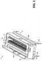
- FIG. 1is a perspective view of an exemplary embodiment of a receptacle connector
- FIG. 2is a partially exploded view of the connector of FIG. 1 ;
- FIG. 3is a schematic view of an insulation base of a connector
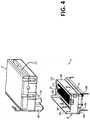
- FIG. 4is a perspective view of the receptacle connector of FIG. 1 in combination with a plug connector:
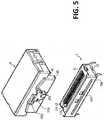
- FIG. 5is a perspective view of the receptacle connector and plug connector of FIG. 4 , shown from an alternative perspective;
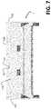
- FIG. 6is a side view of the receptacle and plug connectors of FIG. 4 in a mated configuration:
- FIG. 7is a side view of a receptacle connector
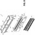
- FIG. 8is a partially exploded view of an alternative embodiment of a receptacle connector:
- FIG. 9is a perspective view of the receptacle connector of FIG. 8 in combination with a plug connector in an unmated configuration:
- FIG. 10is a perspective view of the receptacle connector of FIG. 8 in combination with a plug connector in a mated configuration:
- FIG. 11is a schematic view of an insulation base of the receptacle connector of FIG. 8 ;
- FIG. 12is a perspective, cut away view of the receptacle connector of FIG. 8 in combination with a plug connector in a mated configuration.
- Connector 1 Insulative body 11 Plug interface 110Accommodation space 111 Terminal slot 114 Support part 115 Front Surface 116 Metal terminal 13 Metal housing 15 First side wall 15A Second side wall 15B First end wall 15C Second end wall 15D Assembly space 150 Snap-fit hole 151 Abutting groove 153 Bearing part 154 Pin 155, 156 Upper edge 157 Connector 1′ Insulative body 11′ Further connector 2 Terminal board 21 Cable Opening 22 Abutting wall 23 Springy member 230 Projecting block 231 Pressing piece 232 Plug interface 210 Accommodation space 211 Terminal slot 214 First support part 216 Inclined surface 2161 Abutting recess 218 Relieved portion 219 Relieved portion 220 Metal housing 25 First side wall 25A Extending portion 25C1 Assembly space 250 Snap-fit hole 251 Abutting groove 253 Further connector 3 Terminal board 31 Abutting wall 33 Pressing piece 330 Projecting block 331 Abutting protrusion 332 Axis L Acute angle ⁇
- the inventorshave recognized and appreciated design techniques for electrical connectors that enable mated plug and receptacle connectors to occupy a small volume while providing reliable operation for high integrity signal interconnects. Techniques as described herein may lead to compact, but robust connectors, less likely to be damaged during mating.
- each metal terminal of a receptacle connectorhas been carefully soldered onto a circuit board during the production of electronic devices using the connector, the connector during use will be mated with a further connector. It is preferred that, during mating, the direction of applied force is parallel to the axial direction of the receptacle connector.
- the receptacle connectoris often subject to an external force that is not parallel to the axial direction of the connector, causing the connector to tilt. In some situations, the force will be sufficient to separate the metal terminals from the printed circuit board, so that the connector loses its function, which in turn affects the normal operation of the electronic devices.
- One such techniqueis the incorporation of a space between the receptacle connector housing and a metal shell.
- An example of such a spaceused as an example of this technique below, is an abutting groove.
- the abutting groovemay abut both the connector housing and the metal shell.
- Such a spacemay receive a projection from the housing of a plug connector.
- An example of such a projectionused as an example of this technique below, is an abutting wall.
- the metal shell of the receptacle connectormay have openings that engage with complementary latching elements on the plug connector.
- the latching elementsmay be attached to the projection, enabling the openings and the latching elements to engage closer to the printed circuit board than latching elements mounted to the plug connector housing of known connectors that lacked such a projection.
- the mated height of the receptacle and plug, measured normal to the surface of a printed circuit board to which the receptacle connector is mounted,may therefore be smaller, leading to a more compact connector.
- a connectormay have an abutting groove.
- the connectormay comprise an insulative body, a plurality of metal terminals and a metal housing, wherein the metal terminals can be fixed in the insulative body, and the insulative body, together with the metal terminals, can be assembled into the metal housing.
- the connectormay be characterized in that a first side wall of the metal housing is provided with at least one snap-fit hole and is at a distance from a corresponding side face of the insulative body to form an abutting groove.
- a plurality of terminals of the further connectorcan extend into an accommodation space via a plug interface and are electrically connected to the metal terminals, an abutting wall of the further connector can extend into the abutting groove, and at least one projecting block protruding from an outer side of the abutting wall can be embedded in the corresponding snap-fit hole.
- the abutting groovecan play a guiding role and guide the abutting wall of the further connector to extend into the abutting groove, such that the user can correctly mate the connectors.
- the connectorscan be stably mated.
- the height of the first side wallis higher than the height of the other side walls of the metal housing, so that the abutting wall of the further connector can be more easily engage an inner side face of the first side wall and slide into the abutting groove along the inner side face of the first side wall.
- the first side wallmay guide a plug into a receptacle to facilitate mating, reducing the risk of damage to both the plug and receptacle connectors during mating.
- two opposing end walls of the metal housingmay be configured to further assist in guiding the plug into the receptacle during mating.
- the two opposing end wallsmay have a height in a local region adjacent to the first side wall higher than the height of the remaining end wall of the metal housing.
- the height of the opposing end walls in that local regionmay be equal to the height of the first side wall.
- the height of the opposing end walls outside that local regionmay be equal to the height of the insulative body.
- the abutting wall of the plug connectorcan be constrained between the first side wall and its two adjacent end walls and thus can be guided into the abutting groove.
- the bottom of the first side wallmay be oriented towards the abutting groove to form a bearing part, so that when the abutting wall of the plug connector is pushed into the abutting groove during mating of the plug and receptacle, the bottom face of the abutting wall can abut against the bearing part so as to avoid over-pressing of the plug connector on the receptacle.
- a pressing partwhich when pressed releases the latching of a plug to a receptacle connector, may have a small range of motion.
- a small range of motionthere is a risk of improper operation of the release mechanism which may lead to a user to place a relatively large amount of force of the connectors as the user attempts to un-mate the connectors while they are still latched to one another.
- Designs of the housings of the plug and receptacle to provide a greater range of motioncan increase the reliability of the latch release mechanism, reducing the chances that the connectors will be damaged in use.
- an insulative bodymay be formed with an abutting recess at the periphery of a top face of the insulative body corresponding to the side face that bounds the abutting groove.
- an abutting protrusion of the further connectorcan be accommodated in the abutting recess, so as to form a relieved portion in the abutting wall.
- the abutting recessmay provide a localized region of the abutting groove that is wider than other portions of the abutting groove.
- a latching component of the plug connectormay be positioned to be within this localized region, allowing a greater range of motion of a pressing piece of the latching component.
- Such a greater range of motionmay lead to more certain disengagement of the latching component of the plug connector form corresponding latching components of the receptacle connector, making it easier to de-mate the connectors and/or reducing the risk of damage to one of the connectors that might result from a user pulling on a plug that is still partially latched to a receptacle connector.
- a plugmay including latching components that engage complementary latching components on a receptacle connector.
- a usermust press on a release mechanism on one side of the connector. That pressing force may cause the receptacle to tilt, creating the risk that the metal terminals will detach from the printed circuit board or the connector will be otherwise damaged. That risk may be particularly high for miniaturized electronic parts that are made of thin materials.
- a connector housingthat provides a support, to resist tilting of the connector that could detach the metal terminals from a printed circuit board, on only one side of the connector to reduce the size of the connector. That support may be provided opposite the side of the connector at what latching components are attached.
- the receptacle connectormay have a first support part that protrudes outward from an outer side of the insulative body that is on the opposite side of the connector from the snap-fit hole.
- a housingmay have asymmetric support parts, such as by having a support part protruding from the housing on only one side.
- Such a connectormay be compact. Yet, when the connector is mounted to a circuit board, a bottom face of the first support part can abut against a surface of the circuit board.
- a connector using some or all of these techniquesmay be compact, with a low height.
- the connectormay have a width comparable to a connector that is taller, by forming the connector housing with thin walls. Techniques as described herein nonetheless enable reliable operation as the connector can withstand stresses that occur during use, including during mating and other operating conditions, such as when force is exerted on a cable to which a plug is connected.
- connector 1comprises an insulative body 11 , a plurality of metal terminals 13 and a metal housing 15 .
- the upper part in FIG. 1is taken as a front side the connector 1
- the lower part in FIG. 1is taken as a rear side of the connector.
- Connector 1is configured as a receptacle connector.
- the rear side of connector 1is configured to be mounted to a printed circuit board E ( FIG. 3 ).
- the front sideis configured to provide a mating interface, where connector 1 may mate with a plug connector.
- the insulative body 11is provided at a front side with a plug interface 110 .
- the front surface 116 of insulative body 11is shaped to mechanically receive a mating component, such as a paddle card, of a plug connector.
- insulative body 11has an accommodation space 111 , forming a portion of the plug interface 110 , as the mating component of the plug may fit within accommodation space 111 .
- Two opposite inner side faces of the insulative body 11 bounding accommodation space 111are respectively provided with a plurality of terminal slots 114 . Terminals within the terminal slots 114 are exposed to the accommodation space 111 such that they may make mechanical and electrical contact with a mating component of a plug connector inserted in accommodation space 111 .
- connector 1may be configured in other ways to provide a mating interface to another connector.
- the insulative body 11may have no terminal slots 114 , or a tongue plate may additionally be provided in the insulative body 11 and the terminal slots 114 may be provided on the tongue plate.
- the structure of the present disclosurecan be applied to various types of connectors 1 .
- the metal terminals 13are respectively fixed in the insulative body 11 and are separated from each other at a distance.
- the metal terminals 13can be of different types, such as signal terminal, ground terminal, power terminal, etc., and can be embedded into the respective terminal slots 114 .
- Front ends of the metal terminals 13may serve as mating contact portions and may be exposed in the accommodation space 111 (as shown in FIG. 1 ) so as to be electrically connected to terminals of the further connector 2 ( FIG. 4 ).
- Insulative base 11may include support parts 115 to aid in stably mounting connector 1 to circuit board E.
- Support parts 115respectively protrude outward from outer sides of two opposite side faces thereof, so that where the insulative base 11 is mounted to a circuit board, bottom faces of the two support parts 115 abut against a top face of the circuit board, so as to stabilize the connector 1 .
- support parts 115support the bending load of the insulative base 11 that is caused by the external force.
- the bottom face of the insulative base 11can be stably maintained relative to the printed circuit board so as to avoid the adverse case that the insulation base 11 is tilted excessively under the external force and metal terminals 13 , which are tilted with the insulation base 11 , are disengaged from the circuit board.
- the metal housing 15is formed by bending a metal plate. Where the metal plate is bent into a frame shape, an assembly space 150 running through front and rear sides will be enclosed by the frame. Insulative body 1 can extend into the assembly space 150 and may be fixed in the metal housing 15 (as shown in FIG. 1 ). In this configuration, metal housing 15 may prevent electromagnetic interference (EMI), serve as a grounding route, and/or protect the insulative body 11 . Metal housing 15 may also form a portion of the latching structure that latches a plug connector to connector 1 . At least one snap-fit hole 151 is provided in a first side wall 15 A of the metal housing 15 , which may engage a complementary latching feature of plug connector mated with connector 1 .
- EMIelectromagnetic interference
- Metal housing 15may be shaped to enable a complementary latching feature of a plug connector to engage the at least one snap-fit hole 151 with a low height of the mated connectors.
- An inner side face of the first side wall 15 Ais at a distance from a side face corresponding to the insulative body 11 to form an abutting groove 153 . That is, the assembly space 150 is greater than the volume of the insulative body 11 , such that after the insulative body 11 is assembled to the metal housing 15 , a gap between the two will form the abutting groove 153 .
- a further connector 2configured as a plug, is shown aligned with a receptacle connector 1 .
- Further connector 2is configured for terminating a cable.
- a cable opening 22through which a cable may pass to the interior of an insulative housing of further connector 2 . Inside the housing, conductors of the cable may be attached to terminals of the connector 2 .
- the cableis not show in FIG. 4 .
- Terminal board 21may be implemented as a paddle card.
- a paddle cardfor example, may have a plurality of pads (not shown) on one or more surfaces that act as terminals for mating with connector 1 .
- the terminal board 21can extend into the accommodation space 111 such that the terminals thereon are electrically connected to front ends of the metal terminals 13 so as to exchange signals with each other.
- rear ends of the metal terminals 13will extend from a rear end of the insulative body 11 for electrical and mechanical attachment to a circuit board.
- terminals 13are configured for surface mount soldering to a circuit board, but other attachment techniques may be employed.
- the further connector 2is provided with a projection, here shown as an abutting wall 23 .
- Abutting wall 23extends from the insulative housing of plug connector 2 in an extension direction that is the same as that of the terminal board 21 . Both extend in the mating direction in which connector must be pressed into connector 1 for mating. In this configuration, abutting wall 23 is parallel to and separated by a distance from the terminal board 21 .
- Abutting wall 23may provide a place for attachment of latching components that engage with latching components on connector 1 .
- the latching components on plug connector 2include projecting blocks 231 , which fit within snap-fit holes 151 when the plug and receptacle connectors are mated. At least one projecting block 231 protrudes from an outer side face of the abutting wall 23 . In the embodiment illustrated, there are two projecting blocks 231 .
- Projecting blocks 231are formed on a springy member 230 , mounted to abutting wall 23 .
- That springy memberfor example, may be a sheet of metal that is bent or otherwise formed to have a portion that is attached to abutting wall 23 and a portion that stands off the surface of abutting wall 23 .
- Projecting blocks 231are formed on the portion of the springy member 230 that stands off from abutting wall 23 .
- Projecting blocks 231may be formed, for example, by cutting tabs in the portion that stands off the surface.
- Other portions of the springy membermay form a pressing piece 232 , which may be pressed by a user to force the portion of the springy member with projecting blocks 231 towards the surface of abutting wall 23 . When pressed towards the surface of abutting wall 23 , projecting blocks 231 are pulled out of snap-fit holes 151 .
- the springy member 230is in a position in which projecting blocks 231 are held away from surface of abutting wall 23 .
- Projecting blocks 231have a ramped shape, and may act as camming surfaces to press the springy member towards the surface of abutting wall 23 as they engage first side wall 15 A as the further connector 2 is plugged into the connector 1 .
- the abutting wall 23 of the further connector 2extends into the abutting groove 153 , and at the same time, the projecting blocks 231 can extend into the corresponding snap-fit holes 151 .
- the further connector 2is latched to connector 1 , because the upward edges of projecting blocks 231 engage an upper edge of 157 ( FIG. 7 ) of snap-fit holes 151 .
- the height of the first side wall 15 Acan be higher than that of the other side walls of the metal housing 15 , so that the abutting wall 23 can be more easily pressed against the first side wall 15 A and slide into the abutting groove 153 along the inner side face of the first side wall 15 A.
- two opposite end walls 15 C and 15 D of the metal housing 15 adjacent to the first side wall 15 Amay have a height of a local region adjacent to the first side wall 15 A equal to the height of the first side wall 15 A and higher than the height of the remaining end wall of the metal housing 15 .
- the abutting wall 23 of the further connector 2extends into the abutting groove 153 , the abutting wall 23 will be positioned by the first side wall 15 A and two adjacent opposite end walls 15 C and 15 D, and then can correctly extend into the abutting groove 153 , so that the user can quickly and correctly assemble the connectors 1 and 2 .
- the bottom of the first side wall 15 Awill first bend toward the abutting groove 153 to form a bearing part 154 .
- the bottom face of the abutting wall 23can abut against the bearing part 154 (as shown in FIG. 6 ), so that the user is limited in their ability to press the further connector 2 into the receptacle connector 1 .
- the userreceives tactile feedback that further connector 2 is fully inserted into receptacle connector 1 . Additional force applied by the user after the connectors are fully mated is taken up by abutting wall 23 and bearing part 154 , preventing the user from applying excessive force on the terminals of connectors 1 and 2 , which could cause damage to the connector 1 .
- the bearing part 154can bend again to the rear of the metal housing 15 , and can form at least one pin 155 , which may be soldered, welded or otherwise attached to a printed circuit board to which the connector is mounted. Pin 155 may provide support for bearing part 154 , increasing the amount of stress it can withstand.
- the bottom of the second side wall 15 B of the metal housing 15 opposite the first side wall 15 Amay also be bent to form at least one pin 156 , which may also be attached to a printed circuit board to provide further support.
- the bending direction of the second side wall 15 Bwill be the same as that of the first side wall 15 A, so that the metal housing 15 has better strength and is not easily deformed by external forces.
- FIG. 6is a side view of connector 1 and further connector 2 in a mated configuration.
- Projecting blocks 231can be seen extending through snap-fit holes, such that a portion of projecting blocks 231 is visible outside of metal housing 15 .
- the latching components of connector 1 and further connector 2may be adjacent insulative body 11 when connector 1 and further connector 2 are mated.
- the latching componentsmay be partially or totally below front surface 116 .
- the height H of the mated connectorsmay be less.
- the width, W. of the receptacle connectormay also be made small. Such reduction in size may be achieved in part by reducing the thickness of the walls of the insulative body being made thinner, including those bounding the accommodation space.
- the width of the accommodation spacemay match a thickness of a paddle card set in a specification, such that reduction in width cannot be achieved by reducing the width of the accommodation space.
- the width. Wmay be less than 8 mm or less than 7 mm, in some embodiments, such as between 6 and 7 mm, such as 6.82 mm, for example. Nonetheless, techniques as described herein, including, for example an asymmetric support part, such as is shown in FIG. 8 (below) may nonetheless result in a robust connector with such a reduced width. Moreover, techniques as described herein, such as a recess 218 , enables reliable operation with low stress, even with such a reduced width.
- FIG. 7is a side view of a connector 1 showing the relative height of the upper edges 157 of snap-fit holes 151 and front surface 116 .
- snap-fit holes 151are aligned with front surface 116 , such that a portion of snap-fit holes 151 are below front surface 116 .
- the portions of snap-fit holes 151 below front surface 116are obscured by insulative body 11 and the second side wall 15 B of metal housing 15 .
- upper edges 157are slightly above front surface 116 .
- the present disclosuredescribes a connector with an abutting groove, the connector comprising an insulative body, a plurality of metal terminals and a metal housing, wherein the metal terminals are fixed into the insulative body, and the insulative body can be assembled into the metal housing.
- the connectoris characterized in that a first side wall of the metal housing is provided with at least one snap-fit hole and is at a distance from a corresponding side face of the insulative body to form an abutting groove.
- an abutting wall of the further connectorcan extend into the abutting groove, and at least one projecting block protruding from an outer side of the abutting wall can be embedded into the corresponding snap-fit hole.
- the abutting groove and the snap-fit holecan guide the further connector to be correctly and stably assembled to the connector.
- FIGS. 1-7illustrates a receptacle connector mated with a plug in which the mating direction is at a right angle to the cable entering the plug housing.
- the techniques as described hereinmay be used with plugs of other configurations, such as plugs that have a mating direction perpendicular to a cable entering the insulative housing of the plug.
- FIGS. 8-12illustrate such an embodiment.
- the connector 1 ′comprises an insulative body 11 ′, a plurality of metal terminals 13 and a metal housing 25 .
- the upper part in FIG. 8is taken as a front side position of the connector, while the lower part in FIG. 4 is taken as a rear side position of the connector.
- the insulative body 11 ′is provided at a front side with a plug interface 210 including an accommodation space 211 in insulative body 11 ′.
- a plug interface 210including an accommodation space 211 in insulative body 11 ′.
- two opposite inner side faces of the insulative body 11 ′are respectively provided with a plurality of terminal slots 214 .
- the insulative body 11 ′can also be provided with no terminal slots 214 , or a tongue plate may additionally be provided in the insulative body 11 ′ and the terminal slots 214 may be provided on the tongue plate.
- the structure of the present disclosurecan be applied to various types of connectors.
- the metal terminals 13are respectively fixed in the insulative body 11 ′ and are separated from each other at a distance.
- the metal terminals 13can be of any of multiple types, including signal terminals, ground terminals, power terminals, etc., and can be embedded into the respective terminal slots 214 . Front ends of the metal terminals 13 can be exposed in the accommodation space 211 to be electrically connected to terminals of a further connector 3 .
- the further connector 3is provided with a terminal board 31 , and the terminal board 31 is provided with a plurality of terminals (not shown).
- the further connector 3is here configured as a plug connector terminated to a cable.
- the terminal board 31can extend into the accommodation space 211 of the plug interface 210 such that the terminals thereon are electrically connected to front ends of the metal terminals 13 , thus being able to exchange signals or currents with each other. Further, rear ends of the metal terminals 13 will extend from a rear end of the insulative body 11 ′ (as shown in FIG. 9 ) so as to be attached to a circuit board as described above for connector 1 .
- the metal housing 25is formed by bending a metal plate.
- the metal plateis bent into a frame shape, encircling an assembly space 250 .
- the insulative body 11 ′extend into the assembly space 250 and is fixed inside the metal housing 25 (as shown in FIG. 9 ).
- Metal housing 25may prevent electromagnetic interference (EMI), serve as a grounding route, protect the insulative body 11 ′, and/or perform other functions.
- metal housing 25may include extending portions on the end walls extending towards the printed circuit board to which connector 1 ′ may be mounted. Extending portion 25 C 1 is visible in the embodiment of FIG. 8 and is shown including a tab to attach metal housing 25 to insulative body 11 ′. A similar extending portion may be on the opposing end, but is not visible in the orientation of FIG. 8 .
- At least one snap-fit hole 251is provided in a first side wall 25 A of the metal housing 25 .
- An inner side face of the first side wall 25 Ais at a distance from a side face corresponding to the insulative body 11 ′ to form an abutting groove 253 . That is, the assembly space 250 is greater than the volume of the insulative body 11 ′, such that after the insulative body 11 ′ is assembled to the metal housing 25 , a gap between the two will form the abutting groove 253 .
- At least one first support part 216protrudes outward on an outer side of the other side face of the insulative body 11 ′ away from the snap-fit hole 251 .
- the first support part 216is located in the position of the insulative body 11 ′ near the rear end, but is not limited herein. If the overall volume and cost of the connector 1 are not considered, the front side of the first support part 216 can be connected to the area of the insulative body 11 ′ that is adjacent to the front end or a middle section. Further, the first support part 216 is provided with at least an inclined surface 2161 .
- the inclined surface 2161forms an acute angle ⁇ with an axis L of the insulative body 11 ′.
- the further connector 3is provided with an abutting wall 33 .
- the extension direction of the abutting wall 33is the same as that of the terminal board 31 , and the abutting wall 33 is at a distance from the terminal board 31 .
- an abutting recess 218is recessed at the periphery of a top face of the insulative body 11 ′ corresponding to the side face. Providing the housing of receptacle connector 1 ′ with this configuration, and shaping of abutting wall 33 of further connector 3 to conform to the recess 218 , may reduce the risk that connectors 1 ′ and further connector 3 will not be fully unlatched when a user attempts to un-mate the connectors.
- the insulative housing of further connector 3is shaped with a relieved portion 219 , which conforms to recess 218 .
- Connector 3may have a latching component as described above in connection with further connector 2 .
- a pressing piece 330 and at least one projecting block 331are provided on an outer side face of the abutting wall 33 , and an abutting protrusion 332 (as shown in FIG. 12 ) is provided on an inner side face (i.e. the side face toward the terminal board 31 ) of the abutting wall 33 .
- a bottom end of the pressing piece 330can be fixed to the abutting wall 33 .
- a top end of pressing piece 330keeps a distance from the outer side face of the abutting wall 33 , so that the user can press the top end of the pressing piece 330 .
- the pressing piece 330When pressed by a user, the pressing piece 330 is displaced inwardly (i.e. the direction toward the abutting wall 33 ). Further, the projecting blocks 331 are located on the pressing piece 330 and move with the pressing piece 330 .
- the insulative housing of further connector 3may include relieved portion 219 .
- the relieved portion 219extends only along a portion of the width of abutting wall 33 , enabling the balance of abutting wall 33 to perform guidance and other functions as described above.
- the top end of the pressing piece 330is exposed out of the connector 1 ′.
- the usercan press the top end of the pressing piece 330 with a finger, and at this time, the projecting blocks 331 are detached from the corresponding snap-fit holes 251 so that the user can pull the further connector 3 out of the connector 1 ′.
- Pressing piece 330may be pressed into relieved portion 219 , ensuring that pressing piece 330 may be easily moved by a user to unlatch projecting blocks 331 from the corresponding snap-fit holes 251 .
- the insulative housing of further connector 3may also include a relieved portion 220 , which may receive the top end of the pressing piece 330 , further ensuring that pressing piece 330 may be easily moved.
- configurations of the connector 1 or the metal housing 15 of the present disclosureis not limited as illustrated in FIG. 1 .
- Those skilled in the artcan adjust the type and shape of each component according to product requirements.
Landscapes
- Coupling Device And Connection With Printed Circuit (AREA)
- Details Of Connecting Devices For Male And Female Coupling (AREA)
Abstract
Description
| 1 | |||
| 11 | |||
| 110 | |||
| 111 | |||
| 114 | |||
| 115 | |||
| 116 | |||
| 13 | |||
| 15 | |||
| 15A | |||
| 15B | |||
| 15C | |||
| | |||
| Assembly space | |||
| 150 | |||
| Snap- | 151 | ||
| Abutting | 153 | ||
| 154 | |||
| 155, 156 | |||
| Upper edge | 157 | ||
| 1′ | |||
| 11′ | |||
| Further connector | 2 | ||
| 21 | |||
| 22 | |||
| 23 | |||
| Springy | 230 | ||
| 231 | |||
| 232 | |||
| 210 | |||
| 211 | |||
| 214 | |||
| 216 | |||
| Inclined | 2161 | ||
| Abutting recess | 218 | ||
| Relieved | 219 | ||
| Relieved | 220 | ||
| 25 | |||
| 25A | |||
| Extending portion | | ||
| Assembly space | |||
| 250 | |||
| Snap- | 251 | ||
| 253 | |||
| Further connector | 3 | ||
| 31 | |||
| 33 | |||
| 330 | |||
| 331 | |||
| Abutting | 332 | ||
| Axis | L | ||
| Acute angle | θ | ||
- (1) When the length of the abutting
wall 23 can be greater than that of theterminal board 21, during the assembly of theconnectors 1 and2, the abuttingwall 23 will first extend into the abuttinggroove 153 and is guided by the abuttinggroove 153, such that theterminal board 21 can be inserted into theaccommodation space 111 of theinsulative body 11 in a correct direction so as to avoid over-pressing of theterminal board 21 to themetal terminals 13 to cause deformation and damage to themetal terminals 13; - (2) when the further connector2 is plugged into the
connector 1 by a user in a wrong direction, the abuttingwall 23 and the abuttinggroove 153 can achieve a fool-proof effect, so that the user can plug theconnectors 1 and2 again in the correct direction; and - (3) with the structure of the projecting
block 231 and the snap-fit hole 151, both the further connector2 and theconnector 1 can be fixed to thesame metal housing 15 at the same time so as to ensure the assembly stability of theconnectors 1 and2.
- (1) When the length of the abutting
- (1) Since the
connector 1′ of the present disclosure is provided with afirst support part 216 only on one side, compared with the embodiment ofFIG. 3 , the thickness of theconnector 1′ can be significantly reduced, and the overall volume of theconnector 1′ is effectively reduced, so as not to occupy too much space on the circuit board. - (2) With the design of the
abutting recess 218, the space of the abuttinggroove 253 can be increased, and therefore, the abuttingwall 33 of the further connector3, in the region adjacentabutting recess 218 can be offset fromfirst side wall 25A a distance (as shown by W inFIG. 12 ). The abuttingprotrusion 332 is formed on the inner side face of the abuttingwall 33. As the portion of abuttingwall 33 that fits within abuttingrecess 218 carries thepressing piece 330, pressingpiece 330 may have a range of motion equal to the distance W from the for the displacement of the top end of thepressing piece 330, so that the top end of thepressing piece 330 has more space to be pressed and displaced. Even though the overall volume of theconnector 1′ is reduced, the normal insertion and removal functions between theconnector 1′ and the further connector3 can still be performed. - (3) When the user presses the top end of the
pressing piece 330, theinsulative body 11′ is subject to an external force (as shown by an arrow inFIG. 11 ) which is not parallel to its axis L, as the cross section of thefirst support part 216 mentioned previously is slightly in the shape of a right-angled triangle (i.e. having a structure with an inclined surface2161), the first support part can effectively support the bending load of theinsulative body 11′ that is caused by the external force, such that the bottom face of theinsulative body 11′ can still stably maintain the current state so as to avoid excessive tilting ofinsulative body 11′ under the external force, which could detachmetal terminals 13 from the circuit board to which they are attached.
- (1) Since the
Claims (18)
Priority Applications (1)
| Application Number | Priority Date | Filing Date | Title |
|---|---|---|---|
| US16/827,328US11146025B2 (en) | 2017-12-01 | 2020-03-23 | Compact electrical connector |
Applications Claiming Priority (4)
| Application Number | Priority Date | Filing Date | Title |
|---|---|---|---|
| TW106217949UTWM558483U (en) | 2017-12-01 | 2017-12-01 | Connector with butting slot |
| TW106217949 | 2017-12-01 | ||
| TW107205215UTWM565895U (en) | 2018-04-20 | 2018-04-20 | Connector with single side support and corresponding butt recess and insulating body thereof |
| TW107205215 | 2018-04-20 |
Related Child Applications (1)
| Application Number | Title | Priority Date | Filing Date |
|---|---|---|---|
| US16/827,328ContinuationUS11146025B2 (en) | 2017-12-01 | 2020-03-23 | Compact electrical connector |
Publications (2)
| Publication Number | Publication Date |
|---|---|
| US20190173232A1 US20190173232A1 (en) | 2019-06-06 |
| US10601181B2true US10601181B2 (en) | 2020-03-24 |
Family
ID=66659502
Family Applications (2)
| Application Number | Title | Priority Date | Filing Date |
|---|---|---|---|
| US16/206,753ActiveUS10601181B2 (en) | 2017-12-01 | 2018-11-30 | Compact electrical connector |
| US16/827,328ActiveUS11146025B2 (en) | 2017-12-01 | 2020-03-23 | Compact electrical connector |
Family Applications After (1)
| Application Number | Title | Priority Date | Filing Date |
|---|---|---|---|
| US16/827,328ActiveUS11146025B2 (en) | 2017-12-01 | 2020-03-23 | Compact electrical connector |
Country Status (1)
| Country | Link |
|---|---|
| US (2) | US10601181B2 (en) |
Cited By (44)
| Publication number | Priority date | Publication date | Assignee | Title |
|---|---|---|---|---|
| US10965064B2 (en) | 2019-04-22 | 2021-03-30 | Amphenol East Asia Ltd. | SMT receptacle connector with side latching |
| US11139618B2 (en)* | 2019-11-25 | 2021-10-05 | Lotes Co., Ltd | Electrical module |
| US11146025B2 (en)* | 2017-12-01 | 2021-10-12 | Amphenol East Asia Ltd. | Compact electrical connector |
| US11189971B2 (en)* | 2019-02-14 | 2021-11-30 | Amphenol East Asia Ltd. | Robust, high-frequency electrical connector |
| US20210408732A1 (en)* | 2020-06-28 | 2021-12-30 | Foxconn (Kunshan) Computer Connector Co., Ltd. | Electrical connector having an outer shell and an inner shield to define an engaging groove |
| US11217942B2 (en) | 2018-11-15 | 2022-01-04 | Amphenol East Asia Ltd. | Connector having metal shell with anti-displacement structure |
| JP2022063421A (en)* | 2020-10-12 | 2022-04-22 | 日本航空電子工業株式会社 | connector |
| JP2022063418A (en)* | 2020-10-12 | 2022-04-22 | 日本航空電子工業株式会社 | connector |
| US11431131B2 (en)* | 2020-05-23 | 2022-08-30 | Foxconn (Kunshan) Computer Connector Co., Ltd. | Electrical connector assembly |
| US11444397B2 (en) | 2015-07-07 | 2022-09-13 | Amphenol Fci Asia Pte. Ltd. | Electrical connector with cavity between terminals |
| US11450991B2 (en)* | 2019-12-05 | 2022-09-20 | Tyco Electronics (Shanghai) Co. Ltd. | Connector housing |
| US11469554B2 (en) | 2020-01-27 | 2022-10-11 | Fci Usa Llc | High speed, high density direct mate orthogonal connector |
| US11469548B2 (en) | 2021-02-08 | 2022-10-11 | Amphenol Assembletech (Xiamen) Co., Ltd | Cable connector |
| US11522310B2 (en) | 2012-08-22 | 2022-12-06 | Amphenol Corporation | High-frequency electrical connector |
| US11539171B2 (en) | 2016-08-23 | 2022-12-27 | Amphenol Corporation | Connector configurable for high performance |
| US11569613B2 (en) | 2021-04-19 | 2023-01-31 | Amphenol East Asia Ltd. | Electrical connector having symmetrical docking holes |
| US11575231B2 (en)* | 2020-01-10 | 2023-02-07 | Foxconn (Kunshan) Computer Connector Co., Ltd. | Electrical connector assembly |
| US11588277B2 (en) | 2019-11-06 | 2023-02-21 | Amphenol East Asia Ltd. | High-frequency electrical connector with lossy member |
| US11641073B2 (en) | 2020-10-12 | 2023-05-02 | Japan Aviation Electronics Industry, Limited | Connector |
| US11652307B2 (en) | 2020-08-20 | 2023-05-16 | Amphenol East Asia Electronic Technology (Shenzhen) Co., Ltd. | High speed connector |
| US11664622B2 (en) | 2020-07-15 | 2023-05-30 | Foxconn (Kunshan) Computer Connector Co., Ltd. | Electrical connector having an outer shell and an insulative housing side wall to define an engaging groove and a pair of side grooves |
| US11664623B2 (en) | 2020-07-24 | 2023-05-30 | Foxconn (Kunshan) Computer Connector Co., Ltd. | Plug connector having a latch and a rod slidable to release the latch |
| US11710917B2 (en) | 2017-10-30 | 2023-07-25 | Amphenol Fci Asia Pte. Ltd. | Low crosstalk card edge connector |
| US11715914B2 (en) | 2014-01-22 | 2023-08-01 | Amphenol Corporation | High speed, high density electrical connector with shielded signal paths |
| US11728585B2 (en) | 2020-06-17 | 2023-08-15 | Amphenol East Asia Ltd. | Compact electrical connector with shell bounding spaces for receiving mating protrusions |
| US11757224B2 (en) | 2010-05-07 | 2023-09-12 | Amphenol Corporation | High performance cable connector |
| US11757215B2 (en) | 2018-09-26 | 2023-09-12 | Amphenol East Asia Electronic Technology (Shenzhen) Co., Ltd. | High speed electrical connector and printed circuit board thereof |
| TWI816195B (en)* | 2021-10-07 | 2023-09-21 | 禾昌興業股份有限公司 | Connector |
| US11791580B2 (en) | 2020-08-19 | 2023-10-17 | Foxconn (Kunshan) Computer Connector Co., Ltd. | Plug connector and connector assembly |
| US11799246B2 (en) | 2020-01-27 | 2023-10-24 | Fci Usa Llc | High speed connector |
| US11799230B2 (en) | 2019-11-06 | 2023-10-24 | Amphenol East Asia Ltd. | High-frequency electrical connector with in interlocking segments |
| US11817639B2 (en) | 2020-08-31 | 2023-11-14 | Amphenol Commercial Products (Chengdu) Co., Ltd. | Miniaturized electrical connector for compact electronic system |
| US11817655B2 (en) | 2020-09-25 | 2023-11-14 | Amphenol Commercial Products (Chengdu) Co., Ltd. | Compact, high speed electrical connector |
| US11831092B2 (en) | 2020-07-28 | 2023-11-28 | Amphenol East Asia Ltd. | Compact electrical connector |
| US11843202B2 (en) | 2021-01-18 | 2023-12-12 | Dongguan Luxshare Technologies Co., Ltd | Electrical connector with improved grounding bar |
| US11870171B2 (en) | 2018-10-09 | 2024-01-09 | Amphenol Commercial Products (Chengdu) Co., Ltd. | High-density edge connector |
| US11894636B2 (en) | 2021-01-13 | 2024-02-06 | Foxconn (Kunshan) Computer Connector Co., Ltd. | Electrical connector with structure to secure a shield to an insulating body |
| US11942716B2 (en) | 2020-09-22 | 2024-03-26 | Amphenol Commercial Products (Chengdu) Co., Ltd. | High speed electrical connector |
| US12095187B2 (en) | 2018-12-21 | 2024-09-17 | Amphenol East Asia Ltd. | Robust, miniaturized card edge connector |
| TWI861402B (en)* | 2020-05-23 | 2024-11-11 | 英屬開曼群島商鴻騰精密科技股份有限公司 | Electrical connector and assembly thereof |
| TWI861403B (en)* | 2020-05-23 | 2024-11-11 | 英屬開曼群島商鴻騰精密科技股份有限公司 | Electrical connector and assembly thereof |
| US12176650B2 (en) | 2021-05-05 | 2024-12-24 | Amphenol East Asia Limited (Hong Kong) | Electrical connector with guiding structure and mating groove and method of connecting electrical connector |
| US12300936B2 (en) | 2019-02-19 | 2025-05-13 | Amphenol Corporation | High speed connector |
| US12300920B2 (en) | 2021-08-13 | 2025-05-13 | Amphenol Commercial Products (Chengdu) Co., Ltd. | High performance card edge connector for high bandwidth transmission |
Families Citing this family (20)
| Publication number | Priority date | Publication date | Assignee | Title |
|---|---|---|---|---|
| US10777921B2 (en) | 2017-12-06 | 2020-09-15 | Amphenol East Asia Ltd. | High speed card edge connector |
| CN208797213U (en) | 2018-06-08 | 2019-04-26 | 安费诺电子装配(厦门)有限公司 | A kind of line-end connector and connector assembly of band rotation locking bar |
| CN209016312U (en) | 2018-07-31 | 2019-06-21 | 安费诺电子装配(厦门)有限公司 | A kind of line-end connector and connector assembly |
| JP7144282B2 (en)* | 2018-11-01 | 2022-09-29 | 日本航空電子工業株式会社 | Connectors and connector assemblies |
| CN111355100B (en) | 2018-12-21 | 2023-12-19 | 富士康(昆山)电脑接插件有限公司 | plug connector |
| CN111355101A (en) | 2018-12-21 | 2020-06-30 | 富士康(昆山)电脑接插件有限公司 | Electrical connector |
| CN113193437B (en) | 2020-01-10 | 2022-06-24 | 富士康(昆山)电脑接插件有限公司 | Electric connector and combination thereof |
| CN111244697B (en)* | 2020-01-13 | 2021-06-18 | 番禺得意精密电子工业有限公司 | Electrical connector |
| US11637391B2 (en) | 2020-03-13 | 2023-04-25 | Amphenol Commercial Products (Chengdu) Co., Ltd. | Card edge connector with strength member, and circuit board assembly |
| CN119108858A (en)* | 2020-04-24 | 2024-12-10 | 东莞立讯技术有限公司 | Terminal structure and board-end connector |
| US11682854B2 (en)* | 2020-08-21 | 2023-06-20 | Amphenol Assembletech (Xiamen) Co., Ltd. | Board connector and connector assembly |
| CN112072400A (en) | 2020-09-04 | 2020-12-11 | 东莞立讯技术有限公司 | Electrical connector |
| CN112490774B (en) | 2020-12-16 | 2025-02-18 | 东莞立讯技术有限公司 | Wire-end connectors and connector assemblies |
| CN120357235A (en)* | 2020-12-16 | 2025-07-22 | 东莞立讯技术有限公司 | Board Connectors and Connector Assemblies |
| TWI760985B (en)* | 2020-12-23 | 2022-04-11 | 佳必琪國際股份有限公司 | Plug connector and manufacturing method thereof |
| CN113422249B (en)* | 2021-06-29 | 2022-04-01 | 中航光电科技股份有限公司 | Connector shell with lock catch retaining structure and connector assembly |
| TWM641654U (en)* | 2021-07-19 | 2023-06-01 | 香港商安費諾(東亞)有限公司 | Compact electrical connector |
| TWI843028B (en)* | 2021-11-16 | 2024-05-21 | 禾昌興業股份有限公司 | Mid mount type easy-lock and easy-unlock connector |
| CN216413344U (en)* | 2021-11-24 | 2022-04-29 | 富顶精密组件(深圳)有限公司 | Electrical connector |
| US20250079735A1 (en)* | 2023-09-05 | 2025-03-06 | Foxconn (Kunshan) Computer Connector Co., Ltd. | Electrical connector assembly with improved mating interfaces |
Citations (215)
| Publication number | Priority date | Publication date | Assignee | Title |
|---|---|---|---|---|
| US2996710A (en) | 1945-09-20 | 1961-08-15 | Du Pont | Electromagnetic radiation absorptive article |
| US3002162A (en) | 1958-11-20 | 1961-09-26 | Allen Bradley Co | Multiple terminal filter connector |
| US3134950A (en) | 1961-03-24 | 1964-05-26 | Gen Electric | Radio frequency attenuator |
| US3322885A (en) | 1965-01-27 | 1967-05-30 | Gen Electric | Electrical connection |
| GB1272347A (en) | 1969-12-09 | 1972-04-26 | Amp Inc | Lossy radio frequency ferrite filter |
| US3786372A (en) | 1972-12-13 | 1974-01-15 | Gte Sylvania Inc | Broadband high frequency balun |
| US3825874A (en) | 1973-07-05 | 1974-07-23 | Itt | Electrical connector |
| US3863181A (en) | 1973-12-03 | 1975-01-28 | Bell Telephone Labor Inc | Mode suppressor for strip transmission lines |
| US4155613A (en) | 1977-01-03 | 1979-05-22 | Akzona, Incorporated | Multi-pair flat telephone cable with improved characteristics |
| US4195272A (en) | 1978-02-06 | 1980-03-25 | Bunker Ramo Corporation | Filter connector having contact strain relief means and an improved ground plate structure and method of fabricating same |
| US4276523A (en) | 1979-08-17 | 1981-06-30 | Bunker Ramo Corporation | High density filter connector |
| US4371742A (en) | 1977-12-20 | 1983-02-01 | Graham Magnetics, Inc. | EMI-Suppression from transmission lines |
| US4408255A (en) | 1981-01-12 | 1983-10-04 | Harold Adkins | Absorptive electromagnetic shielding for high speed computer applications |
| US4447105A (en) | 1982-05-10 | 1984-05-08 | Illinois Tool Works Inc. | Terminal bridging adapter |
| US4471015A (en) | 1980-07-01 | 1984-09-11 | Bayer Aktiengesellschaft | Composite material for shielding against electromagnetic radiation |
| US4484159A (en) | 1982-03-22 | 1984-11-20 | Allied Corporation | Filter connector with discrete particle dielectric |
| US4490283A (en) | 1981-02-27 | 1984-12-25 | Mitech Corporation | Flame retardant thermoplastic molding compounds of high electroconductivity |
| US4518651A (en) | 1983-02-16 | 1985-05-21 | E. I. Du Pont De Nemours And Company | Microwave absorber |
| US4519664A (en) | 1983-02-16 | 1985-05-28 | Elco Corporation | Multipin connector and method of reducing EMI by use thereof |
| US4519665A (en) | 1983-12-19 | 1985-05-28 | Amp Incorporated | Solderless mounted filtered connector |
| US4632476A (en) | 1985-08-30 | 1986-12-30 | At&T Bell Laboratories | Terminal grounding unit |
| US4636752A (en) | 1984-06-08 | 1987-01-13 | Murata Manufacturing Co., Ltd. | Noise filter |
| US4682129A (en) | 1983-03-30 | 1987-07-21 | E. I. Du Pont De Nemours And Company | Thick film planar filter connector having separate ground plane shield |
| US4751479A (en) | 1985-09-18 | 1988-06-14 | Smiths Industries Public Limited Company | Reducing electromagnetic interference |
| WO1988005218A1 (en) | 1986-12-24 | 1988-07-14 | Amp Incorporated | Filtered electrical device and method for making same |
| US4761147A (en) | 1987-02-02 | 1988-08-02 | I.G.G. Electronics Canada Inc. | Multipin connector with filtering |
| US4806107A (en) | 1987-10-16 | 1989-02-21 | American Telephone And Telegraph Company, At&T Bell Laboratories | High frequency connector |
| US4846727A (en) | 1988-04-11 | 1989-07-11 | Amp Incorporated | Reference conductor for improving signal integrity in electrical connectors |
| US4846724A (en) | 1986-11-29 | 1989-07-11 | Tokin Corporation | Shielded cable assembly comprising means capable of effectively reducing undesirable radiation of a signal transmitted through the assembly |
| US4878155A (en) | 1987-09-25 | 1989-10-31 | Conley Larry R | High speed discrete wire pin panel assembly with embedded capacitors |
| US4948922A (en) | 1988-09-15 | 1990-08-14 | The Pennsylvania State University | Electromagnetic shielding and absorptive materials |
| US4970354A (en) | 1988-02-21 | 1990-11-13 | Asahi Chemical Research Laboratory Co., Ltd. | Electromagnetic wave shielding circuit and production method thereof |
| US4975084A (en) | 1988-10-17 | 1990-12-04 | Amp Incorporated | Electrical connector system |
| US4992060A (en) | 1989-06-28 | 1991-02-12 | Greentree Technologies, Inc. | Apparataus and method for reducing radio frequency noise |
| US5000700A (en) | 1989-06-14 | 1991-03-19 | Daiichi Denshi Kogyo Kabushiki Kaisha | Interface cable connection |
| US5066236A (en) | 1989-10-10 | 1991-11-19 | Amp Incorporated | Impedance matched backplane connector |
| US5141454A (en) | 1991-11-22 | 1992-08-25 | General Motors Corporation | Filtered electrical connector and method of making same |
| US5150086A (en) | 1990-07-20 | 1992-09-22 | Amp Incorporated | Filter and electrical connector with filter |
| US5166527A (en) | 1991-12-09 | 1992-11-24 | Puroflow Incorporated | Ultraviolet lamp for use in water purifiers |
| US5168432A (en) | 1987-11-17 | 1992-12-01 | Advanced Interconnections Corporation | Adapter for connection of an integrated circuit package to a circuit board |
| US5168252A (en) | 1990-04-02 | 1992-12-01 | Mitsubishi Denki Kabushiki Kaisha | Line filter having a magnetic compound with a plurality of filter elements sealed therein |
| US5176538A (en) | 1991-12-13 | 1993-01-05 | W. L. Gore & Associates, Inc. | Signal interconnector module and assembly thereof |
| US5266055A (en) | 1988-10-11 | 1993-11-30 | Mitsubishi Denki Kabushiki Kaisha | Connector |
| US5280257A (en) | 1992-06-30 | 1994-01-18 | The Whitaker Corporation | Filter insert for connectors and cable |
| US5287076A (en) | 1991-05-29 | 1994-02-15 | Amphenol Corporation | Discoidal array for filter connectors |
| US5334050A (en) | 1992-02-14 | 1994-08-02 | Derek Andrews | Coaxial connector module for mounting on a printed circuit board |
| US5340334A (en) | 1993-07-19 | 1994-08-23 | The Whitaker Corporation | Filtered electrical connector |
| US5346410A (en) | 1993-06-14 | 1994-09-13 | Tandem Computers Incorporated | Filtered connector/adaptor for unshielded twisted pair wiring |
| US5429521A (en) | 1993-06-04 | 1995-07-04 | Framatome Connectors International | Connector assembly for printed circuit boards |
| US5456619A (en) | 1994-08-31 | 1995-10-10 | Berg Technology, Inc. | Filtered modular jack assembly and method of use |
| US5461392A (en) | 1994-04-25 | 1995-10-24 | Hughes Aircraft Company | Transverse probe antenna element embedded in a flared notch array |
| JPH07302649A (en) | 1994-03-03 | 1995-11-14 | Framatome Connectors Internatl | Connector of cable for high frequency signal |
| US5474472A (en) | 1992-04-03 | 1995-12-12 | The Whitaker Corporation | Shielded electrical connector |
| US5484310A (en) | 1993-04-05 | 1996-01-16 | Teradyne, Inc. | Shielded electrical connector |
| US5496183A (en) | 1993-04-06 | 1996-03-05 | The Whitaker Corporation | Prestressed shielding plates for electrical connectors |
| US5499935A (en) | 1993-12-30 | 1996-03-19 | At&T Corp. | RF shielded I/O connector |
| US5551893A (en) | 1994-05-10 | 1996-09-03 | Osram Sylvania Inc. | Electrical connector with grommet and filter |
| US5562497A (en) | 1994-05-25 | 1996-10-08 | Molex Incorporated | Shielded plug assembly |
| US5597328A (en) | 1994-01-13 | 1997-01-28 | Filtec-Filtertechnologie Gmbh | Multi-pole connector with filter configuration |
| US5651702A (en) | 1994-10-31 | 1997-07-29 | Weidmuller Interface Gmbh & Co. | Terminal block assembly with terminal bridging member |
| US5669789A (en) | 1995-03-14 | 1997-09-23 | Lucent Technologies Inc. | Electromagnetic interference suppressing connector array |
| WO1998035409A1 (en) | 1997-02-07 | 1998-08-13 | Teradyne, Inc. | High speed, high density electrical connector |
| US5796323A (en) | 1994-09-02 | 1998-08-18 | Tdk Corporation | Connector using a material with microwave absorbing properties |
| US5831491A (en) | 1996-08-23 | 1998-11-03 | Motorola, Inc. | High power broadband termination for k-band amplifier combiners |
| US5924899A (en) | 1997-11-19 | 1999-07-20 | Berg Technology, Inc. | Modular connectors |
| US5982253A (en) | 1997-08-27 | 1999-11-09 | Nartron Corporation | In-line module for attenuating electrical noise with male and female blade terminals |
| US5981869A (en) | 1996-08-28 | 1999-11-09 | The Research Foundation Of State University Of New York | Reduction of switching noise in high-speed circuit boards |
| US6019616A (en) | 1996-03-01 | 2000-02-01 | Molex Incorporated | Electrical connector with enhanced grounding characteristics |
| EP1018784A1 (en) | 1999-01-08 | 2000-07-12 | FCI's Hertogenbosch BV | Shielded connectors and method for making the same |
| US6152747A (en) | 1998-11-24 | 2000-11-28 | Teradyne, Inc. | Electrical connector |
| US6168469B1 (en) | 1999-10-12 | 2001-01-02 | Hon Hai Precision Ind. Co., Ltd. | Electrical connector assembly and method for making the same |
| US6174203B1 (en) | 1998-07-03 | 2001-01-16 | Sumitomo Wiring Sysytems, Ltd. | Connector with housing insert molded to a magnetic element |
| US6174944B1 (en) | 1998-05-20 | 2001-01-16 | Idemitsu Petrochemical Co., Ltd. | Polycarbonate resin composition, and instrument housing made of it |
| US6217372B1 (en) | 1999-10-08 | 2001-04-17 | Tensolite Company | Cable structure with improved grounding termination in the connector |
| US6293827B1 (en) | 2000-02-03 | 2001-09-25 | Teradyne, Inc. | Differential signal electrical connector |
| US6296496B1 (en) | 2000-08-16 | 2001-10-02 | Hon Hai Precision Ind. Co., Ltd. | Electrical connector and method for attaching the same to a printed circuit board |
| US6299438B1 (en) | 1997-09-30 | 2001-10-09 | Implant Sciences Corporation | Orthodontic articles having a low-friction coating |
| US6299483B1 (en) | 1997-02-07 | 2001-10-09 | Teradyne, Inc. | High speed high density electrical connector |
| US20010042632A1 (en) | 1998-11-19 | 2001-11-22 | Advanced Filtering System Ltd | Filter for wire and cable |
| US6328601B1 (en) | 1998-01-15 | 2001-12-11 | The Siemon Company | Enhanced performance telecommunications connector |
| US6347962B1 (en) | 2001-01-30 | 2002-02-19 | Tyco Electronics Corporation | Connector assembly with multi-contact ground shields |
| US6350134B1 (en) | 2000-07-25 | 2002-02-26 | Tyco Electronics Corporation | Electrical connector having triad contact groups arranged in an alternating inverted sequence |
| US6364711B1 (en) | 2000-10-20 | 2002-04-02 | Molex Incorporated | Filtered electrical connector |
| US20020042223A1 (en) | 2000-08-23 | 2002-04-11 | Yakov Belopolsky | Stacked electrical connector for use with a filter insert |
| US6375510B2 (en) | 2000-03-29 | 2002-04-23 | Sumitomo Wiring Systems, Ltd. | Electrical noise-reducing assembly and member |
| US6398588B1 (en) | 1999-12-30 | 2002-06-04 | Intel Corporation | Method and apparatus to reduce EMI leakage through an isolated connector housing using capacitive coupling |
| US6409543B1 (en) | 2001-01-25 | 2002-06-25 | Teradyne, Inc. | Connector molding method and shielded waferized connector made therefrom |
| US20020089464A1 (en) | 2001-01-05 | 2002-07-11 | Joshi Ashok V. | Ionic shield for devices that emit radiation |
| US6482017B1 (en) | 2000-02-10 | 2002-11-19 | Infineon Technologies North America Corp. | EMI-shielding strain relief cable boot and dust cover |
| US6503103B1 (en) | 1997-02-07 | 2003-01-07 | Teradyne, Inc. | Differential signal electrical connectors |
| US6506076B2 (en) | 2000-02-03 | 2003-01-14 | Teradyne, Inc. | Connector with egg-crate shielding |
| US6517360B1 (en) | 2000-02-03 | 2003-02-11 | Teradyne, Inc. | High speed pressure mount connector |
| US6530790B1 (en) | 1998-11-24 | 2003-03-11 | Teradyne, Inc. | Electrical connector |
| US6565387B2 (en) | 1999-06-30 | 2003-05-20 | Teradyne, Inc. | Modular electrical connector and connector system |
| US6579116B2 (en) | 2001-03-12 | 2003-06-17 | Sentinel Holding, Inc. | High speed modular connector |
| US6582244B2 (en) | 2001-01-29 | 2003-06-24 | Tyco Electronics Corporation | Connector interface and retention system for high-density connector |
| US6595802B1 (en) | 2000-04-04 | 2003-07-22 | Nec Tokin Corporation | Connector capable of considerably suppressing a high-frequency current |
| US6616864B1 (en) | 1998-01-13 | 2003-09-09 | Micron Technology, Inc. | Z-axis electrical contact for microelectronic devices |
| US6652318B1 (en) | 2002-05-24 | 2003-11-25 | Fci Americas Technology, Inc. | Cross-talk canceling technique for high speed electrical connectors |
| US6655966B2 (en) | 2002-03-19 | 2003-12-02 | Tyco Electronics Corporation | Modular connector with grounding interconnect |
| US20040005815A1 (en) | 2000-10-17 | 2004-01-08 | Akinori Mizumura | Shielded backplane connector |
| US20040020674A1 (en) | 2002-06-14 | 2004-02-05 | Laird Technologies, Inc. | Composite EMI shield |
| US6709294B1 (en) | 2002-12-17 | 2004-03-23 | Teradyne, Inc. | Electrical connector with conductive plastic features |
| US6713672B1 (en) | 2001-12-07 | 2004-03-30 | Laird Technologies, Inc. | Compliant shaped EMI shield |
| US6743057B2 (en) | 2002-03-27 | 2004-06-01 | Tyco Electronics Corporation | Electrical connector tie bar |
| US20040115968A1 (en) | 2002-12-17 | 2004-06-17 | Cohen Thomas S. | Connector and printed circuit board for reducing cross-talk |
| US20040121652A1 (en) | 2002-12-20 | 2004-06-24 | Gailus Mark W. | Interconnection system with improved high frequency performance |
| US6776659B1 (en) | 2003-06-26 | 2004-08-17 | Teradyne, Inc. | High speed, high density electrical connector |
| US20040196112A1 (en) | 2003-04-02 | 2004-10-07 | Sun Microsystems, Inc. | Circuit board including isolated signal transmission channels |
| US6814619B1 (en) | 2003-06-26 | 2004-11-09 | Teradyne, Inc. | High speed, high density electrical connector and connector assembly |
| CN1179448C (en) | 1996-09-11 | 2004-12-08 | 惠特克公司 | Connector assembly with shielding module and method of manufacturing the same |
| US6830489B2 (en) | 2002-01-29 | 2004-12-14 | Sumitomo Wiring Systems, Ltd. | Wire holding construction for a joint connector and joint connector provided therewith |
| US20040259419A1 (en) | 2003-06-18 | 2004-12-23 | Payne Jason J | Electrical connector with multi-beam contact |
| US6872085B1 (en) | 2003-09-30 | 2005-03-29 | Teradyne, Inc. | High speed, high density electrical connector assembly |
| US20050133245A1 (en) | 2002-06-28 | 2005-06-23 | Fdk Corporation | Signal transmission cable with connector |
| US20050176835A1 (en) | 2004-01-12 | 2005-08-11 | Toshikazu Kobayashi | Thermally conductive thermoplastic resin compositions |
| US20050233610A1 (en) | 2003-11-05 | 2005-10-20 | Tutt Christopher A | High frequency connector assembly |
| US6979226B2 (en) | 2003-07-10 | 2005-12-27 | J.S.T. Mfg. Co., Ltd. | Connector |
| US20050283974A1 (en) | 2004-06-23 | 2005-12-29 | Richard Robert A | Methods of manufacturing an electrical connector incorporating passive circuit elements |
| US20050287869A1 (en) | 2004-06-23 | 2005-12-29 | Kenny William A | Electrical connector incorporating passive circuit elements |
| US20060068640A1 (en) | 2004-09-30 | 2006-03-30 | Teradyne, Inc. | High speed, high density electrical connector |
| US7044794B2 (en) | 2004-07-14 | 2006-05-16 | Tyco Electronics Corporation | Electrical connector with ESD protection |
| US7057570B2 (en) | 2003-10-27 | 2006-06-06 | Raytheon Company | Method and apparatus for obtaining wideband performance in a tapered slot antenna |
| CN1799290A (en) | 2003-06-02 | 2006-07-05 | 日本电气株式会社 | Compact via transmission line for printed circuit board and its designing method |
| US7074086B2 (en) | 2003-09-03 | 2006-07-11 | Amphenol Corporation | High speed, high density electrical connector |
| US7094102B2 (en) | 2004-07-01 | 2006-08-22 | Amphenol Corporation | Differential electrical connector assembly |
| US7108556B2 (en) | 2004-07-01 | 2006-09-19 | Amphenol Corporation | Midplane especially applicable to an orthogonal architecture electronic system |
| JP2006344524A (en) | 2005-06-09 | 2006-12-21 | Molex Inc | Connector device |
| US20070004282A1 (en) | 2005-06-30 | 2007-01-04 | Teradyne, Inc. | High speed high density electrical connector |
| WO2007005597A2 (en) | 2005-06-30 | 2007-01-11 | Amphenol Corporation | Connector with improved shielding in mating contact region |
| US20070021001A1 (en) | 2005-03-31 | 2007-01-25 | Laurx John C | High-density, robust connector with castellations |
| US20070037419A1 (en) | 2005-03-28 | 2007-02-15 | Leviton Manufacturing Co., Inc. | Discontinued cable shield system and method |
| US20070054554A1 (en) | 2005-09-06 | 2007-03-08 | Teradyne, Inc. | Connector with reference conductor contact |
| US20070059961A1 (en) | 2005-06-30 | 2007-03-15 | Cartier Marc B | Electrical connector for interconnection assembly |
| CN101176389A (en) | 2005-05-16 | 2008-05-07 | 泰瑞达公司 | Impedance controlled via structure |
| US20080248660A1 (en) | 2007-04-04 | 2008-10-09 | Brian Kirk | High speed, high density electrical connector with selective positioning of lossy regions |
| US20080248659A1 (en) | 2007-04-04 | 2008-10-09 | Cohen Thomas S | Electrical connector with complementary conductive elements |
| US20080246555A1 (en) | 2007-04-04 | 2008-10-09 | Brian Kirk | Differential electrical connector with skew control |
| US20080248658A1 (en) | 2007-04-04 | 2008-10-09 | Cohen Thomas S | Electrical connector lead frame |
| US20090011645A1 (en) | 2007-06-20 | 2009-01-08 | Molex Incorporated | Mezzanine-style connector with serpentine ground structure |
| US20090035955A1 (en) | 2007-08-03 | 2009-02-05 | Mcnamara David Michael | Electrical connector with divider shields to minimize crosstalk |
| US7494383B2 (en) | 2007-07-23 | 2009-02-24 | Amphenol Corporation | Adapter for interconnecting electrical assemblies |
| US20090061661A1 (en) | 2007-08-30 | 2009-03-05 | Shuey Joseph B | Mezzanine-type electrical connectors |
| US20090117386A1 (en) | 2007-11-07 | 2009-05-07 | Honeywell International Inc. | Composite cover |
| US7588464B2 (en) | 2007-02-23 | 2009-09-15 | Kim Yong-Up | Signal cable of electronic machine |
| US20090258516A1 (en) | 2007-07-05 | 2009-10-15 | Super Talent Electronics, Inc. | USB Device With Connected Cap |
| US20090291593A1 (en) | 2005-06-30 | 2009-11-26 | Prescott Atkinson | High frequency broadside-coupled electrical connector |
| CN101600293A (en) | 2008-06-05 | 2009-12-09 | 鸿富锦精密工业(深圳)有限公司 | A printed circuit board |
| US20090305530A1 (en)* | 2005-06-30 | 2009-12-10 | Nokia Corporation | Board Mounted Connector |
| US20090305533A1 (en) | 2008-06-10 | 2009-12-10 | 3M Innovative Properties Company | System and method of surface mount electrical connection |
| US20100048058A1 (en) | 2008-08-19 | 2010-02-25 | Chad William Morgan | Electrical connector with electrically shielded terminals |
| WO2010030622A1 (en) | 2008-09-09 | 2010-03-18 | Molex Incorporated | Connector with impedance tuned terminal arrangement |
| EP2169770A2 (en) | 2008-09-29 | 2010-03-31 | Amphenol Corporation | Ground sleeve having improved impedance control and high frequency performance |
| WO2010039188A1 (en) | 2008-09-23 | 2010-04-08 | Amphenol Corporation | High density electrical connector |
| US7731537B2 (en) | 2007-06-20 | 2010-06-08 | Molex Incorporated | Impedance control in connector mounting areas |
| US7806729B2 (en) | 2008-02-12 | 2010-10-05 | Tyco Electronics Corporation | High-speed backplane connector |
| US20100294530A1 (en) | 2008-09-29 | 2010-11-25 | Prescott Atkinson | Ground sleeve having improved impedance control and high frequency performance |
| US7887379B2 (en) | 2008-01-16 | 2011-02-15 | Amphenol Corporation | Differential pair inversion for reduction of crosstalk in a backplane system |
| US20110104948A1 (en) | 2009-11-04 | 2011-05-05 | Amphenol Corporation | Surface mount footprint in-line capacitance |
| CN201846527U (en) | 2009-03-25 | 2011-05-25 | 莫列斯公司 | High-date rate connector system and circuit board thereof |
| US20110143605A1 (en) | 2009-03-02 | 2011-06-16 | Tyco Electronics Corporation | Electrical connector with contact spacing member |
| US7985097B2 (en) | 2006-12-20 | 2011-07-26 | Amphenol Corporation | Electrical connector assembly |
| US20110212650A1 (en) | 2008-08-28 | 2011-09-01 | Molex Incorporated | Connector with overlapping ground configuration |
| US20110230096A1 (en) | 2010-02-24 | 2011-09-22 | Amphenol Corporation | High bandwidth connector |
| US20110256739A1 (en) | 2010-02-18 | 2011-10-20 | Panasonic Corporation | Receptacle, printed wiring board, and electronic device |
| US20110287663A1 (en) | 2010-05-21 | 2011-11-24 | Gailus Mark W | Electrical connector incorporating circuit elements |
| EP2405537A1 (en) | 2010-07-06 | 2012-01-11 | Hosiden Corporation | Surface mount multi-connector and electronic apparatus having the same |
| US20120094536A1 (en) | 2010-05-21 | 2012-04-19 | Khilchenko Leon | Electrical connector having thick film layers |
| US8216001B2 (en) | 2010-02-01 | 2012-07-10 | Amphenol Corporation | Connector assembly having adjacent differential signal pairs offset or of different polarity |
| CN102598430A (en) | 2009-09-09 | 2012-07-18 | 安费诺有限公司 | Compressive contact for high speed electrical connector |
| US20120184154A1 (en) | 2008-12-02 | 2012-07-19 | Panduit Corp. | Method and System for Improving Crosstalk Attenuation Within a Plug/Jack Connection and Between Nearby Plug/Jack Combinations |
| US20120202386A1 (en) | 2011-02-02 | 2012-08-09 | Amphenol Corporation | Mezzanine connector |
| CN202395248U (en) | 2011-11-23 | 2012-08-22 | 广迎工业股份有限公司 | Improved Structure of USB Male Wire-end Connector |
| US20120214344A1 (en) | 2011-02-18 | 2012-08-23 | Cohen Thomas S | High speed, high density electrical connector |
| US8348701B1 (en)* | 2011-11-02 | 2013-01-08 | Cheng Uei Precision Industry Co., Ltd. | Cable connector assembly |
| US20130012038A1 (en) | 2009-11-13 | 2013-01-10 | Amphenol Corporation | High performance, small form factor connector |
| US20130078870A1 (en) | 2010-05-07 | 2013-03-28 | Amphenol Corporation | High performance cable connector |
| US20130109232A1 (en) | 2011-10-17 | 2013-05-02 | Amphenol Corporation | Electrical connector with hybrid shield |
| US20130217263A1 (en) | 2012-02-22 | 2013-08-22 | Hon Hai Precision Industry Co., Ltd. | High speed high density connector assembly |
| US20130316590A1 (en) | 2012-05-25 | 2013-11-28 | Hon Hai Precision Industry Co., Ltd. | Electrical connector with spacer |
| US20140004724A1 (en) | 2012-06-29 | 2014-01-02 | Amphenol Corporation | Printed circuit board for rf connector mounting |
| US20140057498A1 (en) | 2012-08-22 | 2014-02-27 | Amphenol Corporation | High-frequency electrical connector |
| US8715003B2 (en) | 2009-12-30 | 2014-05-06 | Fci Americas Technology Llc | Electrical connector having impedance tuning ribs |
| US20140273627A1 (en) | 2013-03-14 | 2014-09-18 | Amphenol Corporation | Differential electrical connector with improved skew control |
| US20140273557A1 (en) | 2013-03-13 | 2014-09-18 | Amphenol Corporation | Housing for a high speed electrical connector |
| US20140377992A1 (en) | 2013-06-19 | 2014-12-25 | Hon Hai Precision Industry Co., Ltd. | Electrical connector having improved shileding members |
| US8944831B2 (en) | 2012-04-13 | 2015-02-03 | Fci Americas Technology Llc | Electrical connector having ribbed ground plate with engagement members |
| CN104409906A (en) | 2014-11-25 | 2015-03-11 | 上海航天科工电器研究院有限公司 | High-speed electric transmission connector requiring slight plug-pull force |
| US20150111427A1 (en) | 2013-10-21 | 2015-04-23 | Foxconn Interconnect Technology Limited | Electrical connector with improved contacts |
| US20150236452A1 (en) | 2014-01-22 | 2015-08-20 | Amphenol Corporation | High speed, high density electrical connector with shielded signal paths |
| WO2017007429A1 (en) | 2015-07-07 | 2017-01-12 | Amphenol Fci Asia Pte. Ltd. | Electrical connector |
| US9742132B1 (en)* | 2016-06-14 | 2017-08-22 | Speed Tech Corp. | Electrical connector on circuit board |
| CN206712089U (en) | 2017-03-09 | 2017-12-05 | 安费诺电子装配(厦门)有限公司 | A kind of high speed connector combination of compact |
| US20170352970A1 (en)* | 2016-06-07 | 2017-12-07 | Alltop Electronics (Suzhou) Ltd. | Electrical connector |
| US20180062323A1 (en) | 2016-08-23 | 2018-03-01 | Amphenol Corporation | Connector configurable for high performance |
| TWM558482U (en) | 2017-12-01 | 2018-04-11 | Amphenol East Asia Ltd | Metal shell with multiple stabilizing structures and connector thereof |
| TWM558481U (en) | 2017-12-01 | 2018-04-11 | Amphenol East Asia Ltd | Metal shell formed with connection portion at corners and connector thereof |
| TWM558483U (en) | 2017-12-01 | 2018-04-11 | Amphenol East Asia Ltd | Connector with butting slot |
| TWM559006U (en) | 2017-12-15 | 2018-04-21 | Amphenol East Asia Ltd | Connector having signal terminals and ground terminals in different pitches and having ribs |
| TWM559007U (en) | 2017-12-01 | 2018-04-21 | Amphenol East Asia Ltd | Connector with reinforced supporting portion formed on insulation body |
| TWM560138U (en) | 2018-01-03 | 2018-05-11 | Amphenol East Asia Ltd | Connector with conductive plastic piece |
| TWM562507U (en) | 2017-12-06 | 2018-06-21 | Amphenol East Asia Ltd | Connector provided with conductive plastic member in insulating body |
| US20180205177A1 (en)* | 2017-01-17 | 2018-07-19 | Lotes Co., Ltd. | Electrical connector |
| US20180212376A1 (en)* | 2017-01-25 | 2018-07-26 | Lotes Co., Ltd | Electrical connector |
| CN207677189U (en) | 2018-01-16 | 2018-07-31 | 安费诺电子装配(厦门)有限公司 | A kind of connector assembly |
| TWM565894U (en) | 2018-02-13 | 2018-08-21 | 香港商安費諾(東亞)有限公司 | Connector with joint base |
| TWM565901U (en) | 2018-04-19 | 2018-08-21 | 香港商安費諾(東亞)有限公司 | High-frequency connector that effectively improves anti-EMI performance with grounded metal casing |
| TWM565895U (en) | 2018-04-20 | 2018-08-21 | 香港商安費諾(東亞)有限公司 | Connector with single side support and corresponding butt recess and insulating body thereof |
| TWM565899U (en) | 2018-04-10 | 2018-08-21 | 香港商安費諾(東亞)有限公司 | Metal housing with bent welded structure and connector thereof |
| TWM565900U (en) | 2018-04-19 | 2018-08-21 | 香港商安費諾(東亞)有限公司 | High-frequency connector with lapped gold fingers added on grounded metal casing |
| US20180269607A1 (en)* | 2017-03-16 | 2018-09-20 | Luxshare Precision Industry Co., Ltd | Plug and electrical connector component |
| US20190052019A1 (en)* | 2017-08-08 | 2019-02-14 | Speed Tech Corp. | High frequency connector |
| US20190067854A1 (en)* | 2017-08-23 | 2019-02-28 | Lotes Co., Ltd | Electrical connector |
| US10270191B1 (en)* | 2017-03-16 | 2019-04-23 | Luxshare Precision Industry Co., Ltd. | Plug and connector assembly |
| US20190173209A1 (en) | 2017-12-06 | 2019-06-06 | Amphenol East Asia Ltd. | High speed card edge connector |
Family Cites Families (115)
| Publication number | Priority date | Publication date | Assignee | Title |
|---|---|---|---|---|
| US4728762A (en) | 1984-03-22 | 1988-03-01 | Howard Roth | Microwave heating apparatus and method |
| US4687267A (en) | 1986-06-27 | 1987-08-18 | Amp Incorporated | Circuit board edge connector |
| US4787548A (en) | 1987-07-27 | 1988-11-29 | Pace Incorporated | Nozzle structure for soldering and desoldering |
| JPH03156761A (en) | 1989-11-14 | 1991-07-04 | Mitsubishi Electric Corp | Recorded signal reproducing device |
| US5171161A (en) | 1991-05-09 | 1992-12-15 | Molex Incorporated | Electrical connector assemblies |
| GB9205087D0 (en) | 1992-03-09 | 1992-04-22 | Amp Holland | Sheilded back plane connector |
| US5915976A (en) | 1997-02-06 | 1999-06-29 | Hon Hai Precision Ind. Co., Ltd. | High speed connector |
| US6595801B1 (en) | 1997-05-30 | 2003-07-22 | Molex Incorporated | Electrical connector with electrically isolated ESD and EMI shields |
| US5885088A (en) | 1997-07-14 | 1999-03-23 | Molex Incorporated | Electrical connector assembly with polarization means |
| JP2000223217A (en) | 1999-01-27 | 2000-08-11 | Mitsumi Electric Co Ltd | Small-sized connector |
| US6394842B1 (en) | 1999-04-01 | 2002-05-28 | Fujitsu Takamisawa Component Limited | Cable connecting structure |
| JP3362014B2 (en) | 1999-06-29 | 2003-01-07 | エヌイーシートーキン株式会社 | Lock and unlock structure of cable connector and method of locking and unlocking |
| US6305986B1 (en) | 2000-05-18 | 2001-10-23 | Hon Hai Precision Ind. Co., Ltd. | Cable connector assembly having improved grounding means |
| JP2002151190A (en) | 2000-11-14 | 2002-05-24 | Yazaki Corp | Board connector |
| US6551140B2 (en) | 2001-05-09 | 2003-04-22 | Hon Hai Precision Ind. Co., Ltd. | Electrical connector having differential pair terminals with equal length |
| US6565390B2 (en) | 2001-10-22 | 2003-05-20 | Hon Hai Precision Ind. Co., Ltd. | Polarizing system receiving compatible polarizing system for blind mate connector assembly |
| TW532627U (en) | 2001-12-26 | 2003-05-11 | Hon Hai Prec Ind Co Ltd | Electrical connector |
| US6953351B2 (en) | 2002-06-21 | 2005-10-11 | Molex Incorporated | High-density, impedance-tuned connector having modular construction |
| US6726492B1 (en) | 2003-05-30 | 2004-04-27 | Hon Hai Precision Ind. Co., Ltd. | Grounded electrical connector |
| CN2665985Y (en) | 2003-08-30 | 2004-12-22 | 富士康(昆山)电脑接插件有限公司 | Electric connector |
| US7086872B2 (en) | 2003-11-20 | 2006-08-08 | Tyco Electronics Corporation | Two piece surface mount header assembly having a contact alignment member |
| WO2006010100A1 (en) | 2004-07-07 | 2006-01-26 | Molex Incorporated | Mechanism for delatching small size plug connectors |
| US7322845B2 (en) | 2004-12-16 | 2008-01-29 | Molex Incorporated | Connector delatching mechanism with return action |
| TWM291116U (en) | 2005-11-24 | 2006-05-21 | Joinsoon Electronic Mfg Co Ltd | EMI-elimination structure for connector set |
| EP1791220A1 (en) | 2005-11-28 | 2007-05-30 | Hon Hai Precision Industry Co., Ltd. | High speed card edge connector |
| SG132555A1 (en) | 2005-11-29 | 2007-06-28 | J S T Mfg Co Ltd | Female connector and male connector |
| CN2896615Y (en) | 2005-12-13 | 2007-05-02 | 建舜电子制造股份有限公司 | Double-row type terminal core for connectors |
| TWM297565U (en) | 2006-01-23 | 2006-09-11 | Amphenol Taiwan Corp | Micro socket connector |
| US7407413B2 (en) | 2006-03-03 | 2008-08-05 | Fci Americas Technology, Inc. | Broadside-to-edge-coupling connector system |
| CN2930006Y (en) | 2006-05-26 | 2007-08-01 | 建舜电子制造股份有限公司 | Connector with EMI reduction structure |
| US20080020640A1 (en) | 2006-07-24 | 2008-01-24 | Hon Hai Precision Ind. Co., Ltd. | Electrical connector with shell |
| US7318740B1 (en) | 2006-08-08 | 2008-01-15 | Tyco Electronics Corporation | Electrical connector having a pull tab |
| US7892014B2 (en) | 2007-04-04 | 2011-02-22 | John Mezzalingua Associates, Inc. | Releasably engaging high definition multimedia interface plug |
| CN101048034A (en) | 2007-04-30 | 2007-10-03 | 华为技术有限公司 | Circuitboard interconnection system, connector component, circuit board and circuit board processing method |
| CN100593268C (en) | 2007-05-26 | 2010-03-03 | 贵州航天电器股份有限公司 | High-speed data transmission electric connector with double shielding function |
| US7699644B2 (en) | 2007-09-28 | 2010-04-20 | Tyco Electronics Corporation | Electrical connector with protective member |
| DK2623599T3 (en) | 2007-10-04 | 2019-04-08 | Roche Innovation Ct Copenhagen As | Micromirers |
| CN101459299B (en) | 2007-12-11 | 2010-11-17 | 富士康(昆山)电脑接插件有限公司 | Electric connector |
| US7473124B1 (en) | 2008-02-29 | 2009-01-06 | Tyco Electronics Corporation | Electrical plug assembly with bi-directional push-pull actuator |
| US7645165B2 (en) | 2008-03-17 | 2010-01-12 | Hon Hai Precision Ind. Co., Ltd. | Electrical connector with improved shielding shell |
| JP4795381B2 (en) | 2008-05-01 | 2011-10-19 | タイコエレクトロニクスジャパン合同会社 | Electrical connector assembly |
| US7467977B1 (en) | 2008-05-08 | 2008-12-23 | Hon Hai Precision Ind. Co., Ltd. | Electrical connector with additional mating port |
| KR101578791B1 (en) | 2008-06-04 | 2015-12-18 | 호시덴 가부시기가이샤 | Electric connector |
| US7690946B2 (en) | 2008-07-29 | 2010-04-06 | Tyco Electronics Corporation | Contact organizer for an electrical connector |
| CN201285892Y (en) | 2008-09-16 | 2009-08-05 | 富士康(昆山)电脑接插件有限公司 | Electric connector component |
| TWM357050U (en) | 2008-10-08 | 2009-05-11 | Taiwin Electronics Co Ltd | Two-in-one connector |
| JP2010108800A (en) | 2008-10-31 | 2010-05-13 | Japan Aviation Electronics Industry Ltd | Connector |
| TWM357771U (en) | 2008-11-03 | 2009-05-21 | Hon Hai Prec Ind Co Ltd | Electrical connector |
| CN201323275Y (en) | 2008-11-14 | 2009-10-07 | 富士康(昆山)电脑接插件有限公司 | Electric connector |
| US7871296B2 (en) | 2008-12-05 | 2011-01-18 | Tyco Electronics Corporation | High-speed backplane electrical connector system |
| US7976318B2 (en) | 2008-12-05 | 2011-07-12 | Tyco Electronics Corporation | Electrical connector system |
| US9011177B2 (en) | 2009-01-30 | 2015-04-21 | Molex Incorporated | High speed bypass cable assembly |
| CN201374434Y (en) | 2009-02-09 | 2009-12-30 | 富士康(昆山)电脑接插件有限公司 | Electric connector |
| JP5090432B2 (en) | 2009-12-21 | 2012-12-05 | ヒロセ電機株式会社 | Fitting guide part for electric connector and electric connector device having the same |
| US7883369B1 (en) | 2010-02-24 | 2011-02-08 | Cheng Uei Precision Industry Co., Ltd. | Receptacle connector |
| US8764492B2 (en) | 2010-11-04 | 2014-07-01 | Taiwin Electronics Co., Ltd. | Terminal structure of connector and connector port incorporating same |
| CN102487166B (en) | 2010-12-06 | 2016-03-16 | Bks工程公司 | Multipolar outlet for conductor connection system and connection system thereof |
| CN102593661B (en) | 2011-01-14 | 2014-07-02 | 富士康(昆山)电脑接插件有限公司 | Electric connector |
| CN202009112U (en) | 2011-01-25 | 2011-10-12 | 富士康(昆山)电脑接插件有限公司 | Electric connector component |
| CN102646899B (en) | 2011-02-18 | 2015-04-01 | 富士康(昆山)电脑接插件有限公司 | Electrical connector assembly |
| CN102646900B (en) | 2011-02-18 | 2014-08-27 | 富士康(昆山)电脑接插件有限公司 | Electrical Connector Assembly |
| CN102738660B (en) | 2011-03-31 | 2015-10-07 | 富士康(昆山)电脑接插件有限公司 | Electric connector and assembly thereof |
| CN102769230B (en) | 2011-05-06 | 2016-02-03 | 富士康(昆山)电脑接插件有限公司 | Pin connector |
| US8506319B2 (en) | 2011-06-27 | 2013-08-13 | Tyco Electronics Corporation | Actuator for a connector |
| CN103378481B (en) | 2012-04-28 | 2015-10-07 | 富士康(昆山)电脑接插件有限公司 | Connector module |
| TWM446986U (en) | 2012-07-13 | 2013-02-11 | Hon Hai Prec Ind Co Ltd | Electrical connector |
| US9203176B2 (en) | 2012-07-20 | 2015-12-01 | Advanced-Connetek Inc. | Plug connector |
| CN202695861U (en) | 2012-08-18 | 2013-01-23 | 温州意华通讯接插件有限公司 | Electric connector |
| CN104737384B (en) | 2012-10-18 | 2017-06-16 | 山一电机株式会社 | Socket connector, plug connector and possesses the electric connector of both |
| TWI514693B (en) | 2012-10-18 | 2015-12-21 | Hon Hai Prec Ind Co Ltd | An electrical connector plug can be forward or reverse connected and assembly thereof |
| US9142921B2 (en) | 2013-02-27 | 2015-09-22 | Molex Incorporated | High speed bypass cable for use with backplanes |
| US8864506B2 (en) | 2013-03-04 | 2014-10-21 | Hon Hai Precision Industry Co., Ltd. | Cable connector with improved grounding plate |
| CN203445304U (en) | 2013-07-12 | 2014-02-19 | 富士康(昆山)电脑接插件有限公司 | Electric connector |
| US9350126B2 (en) | 2013-07-19 | 2016-05-24 | Foxconn Interconnect Technology Limited | Electrical connector having a receptacle with a shielding plate and a mating plug with metallic side arms |
| CN104425995B (en) | 2013-09-06 | 2017-01-18 | 富士康(昆山)电脑接插件有限公司 | Electrical connector and assembly thereof |
| TWM474278U (en) | 2013-09-09 | 2014-03-11 | Hon Hai Prec Ind Co Ltd | Electrical connector |
| CN203690614U (en) | 2013-10-18 | 2014-07-02 | 富士康(昆山)电脑接插件有限公司 | Electric connector |
| CN203631874U (en) | 2013-11-01 | 2014-06-04 | 富士康(昆山)电脑接插件有限公司 | Electric connector |
| JP5887326B2 (en) | 2013-12-12 | 2016-03-16 | モレックス エルエルシー | connector |
| US9431772B2 (en) | 2013-12-19 | 2016-08-30 | Apple Inc. | Connector retention features |
| CN204030057U (en) | 2014-07-22 | 2014-12-17 | 实盈电子(东莞)有限公司 | A kind of Board-to-Board Electrical Connector |
| CN204167554U (en) | 2014-10-09 | 2015-02-18 | 至良科技股份有限公司 | Terminal structure and electrical connector with the terminal structure |
| US9337585B1 (en) | 2014-12-05 | 2016-05-10 | All Best Precision Technology Co., Ltd. | Terminal structure and electrical connector having the same |
| CN204558802U (en) | 2014-12-22 | 2015-08-12 | 富士康(昆山)电脑接插件有限公司 | Electric connector |
| CN204349140U (en) | 2014-12-25 | 2015-05-20 | 东莞联基电业有限公司 | Multifunctional integrated connector socket, plug and combination thereof |
| US9692183B2 (en) | 2015-01-20 | 2017-06-27 | Te Connectivity Corporation | Receptacle connector with ground bus |
| TWI535129B (en) | 2015-02-06 | 2016-05-21 | 莫仕股份有限公司 | Connector assembly and receptacle connector thereof |
| US9768560B2 (en) | 2015-06-01 | 2017-09-19 | Foxconn Interconnect Technology Limited | Electrical connector having improved shielding shell |
| US9640915B2 (en) | 2015-07-13 | 2017-05-02 | Te Connectivity Corporation | Electrical connector with a programmable ground tie bar |
| US9843135B2 (en) | 2015-07-31 | 2017-12-12 | Samtec, Inc. | Configurable, high-bandwidth connector |
| CN107681371B (en) | 2016-08-01 | 2020-06-02 | 富士康(昆山)电脑接插件有限公司 | Electrical connector |
| CN107871987B (en) | 2016-09-23 | 2020-10-30 | 富士康(昆山)电脑接插件有限公司 | Electrical connector |
| TWI596840B (en) | 2016-11-11 | 2017-08-21 | Molex Llc | Electrical connectors |
| CN107046206B (en) | 2017-01-23 | 2021-07-20 | 富士康(昆山)电脑接插件有限公司 | Electrical connector |
| US10404014B2 (en) | 2017-02-17 | 2019-09-03 | Fci Usa Llc | Stacking electrical connector with reduced crosstalk |
| TWM553887U (en)* | 2017-04-06 | 2018-01-01 | 宣德科技股份有限公司 | Electrical connector structure |
| JP6842359B2 (en) | 2017-05-10 | 2021-03-17 | モレックス エルエルシー | connector |
| CN207338696U (en) | 2017-06-28 | 2018-05-08 | 安费诺商用电子产品(成都)有限公司 | Miniaturized high-speed card-inserted connector |
| US10431936B2 (en) | 2017-09-28 | 2019-10-01 | Te Connectivity Corporation | Electrical connector with impedance control members at mating interface |
| CN114512840B (en) | 2017-10-30 | 2024-06-25 | 安费诺富加宜(亚洲)私人有限公司 | Low crosstalk card edge connector |
| TWM562506U (en) | 2017-11-15 | 2018-06-21 | 宣德科技股份有限公司 | Electrical connector |
| US10601181B2 (en) | 2017-12-01 | 2020-03-24 | Amphenol East Asia Ltd. | Compact electrical connector |
| CN208078300U (en) | 2018-04-26 | 2018-11-09 | 安费诺商用电子产品(成都)有限公司 | Connector |
| CN208797273U (en) | 2018-09-03 | 2019-04-26 | 安费诺电子装配(厦门)有限公司 | A kind of drawstring unlocking type wire and cable connector and connector assembly |
| CN209169509U (en) | 2018-09-29 | 2019-07-26 | 富士康(昆山)电脑接插件有限公司 | Pin connector and socket connector |
| TWM576774U (en)* | 2018-11-15 | 2019-04-11 | 香港商安費諾(東亞)有限公司 | Metal case with anti-displacement structure and connector thereof |
| CN111355100B (en)* | 2018-12-21 | 2023-12-19 | 富士康(昆山)电脑接插件有限公司 | plug connector |
| US11381015B2 (en)* | 2018-12-21 | 2022-07-05 | Amphenol East Asia Ltd. | Robust, miniaturized card edge connector |
| CN111355101A (en)* | 2018-12-21 | 2020-06-30 | 富士康(昆山)电脑接插件有限公司 | Electrical connector |
| US20200259294A1 (en) | 2019-02-07 | 2020-08-13 | Amphenol East Asia Ltd. | Robust, compact electrical connector |
| US11189971B2 (en) | 2019-02-14 | 2021-11-30 | Amphenol East Asia Ltd. | Robust, high-frequency electrical connector |
| TWM582251U (en) | 2019-04-22 | 2019-08-11 | 香港商安費諾(東亞)有限公司 | Connector set with hidden locking mechanism and socket connector thereof |
| CN210326355U (en) | 2019-07-25 | 2020-04-14 | 香港商安费诺(东亚)有限公司 | Conductive grounding piece with open structure and its connector |
| TWM605564U (en) | 2020-07-15 | 2020-12-21 | 台灣莫仕股份有限公司 | Connector and electrical connector device |
| CN112072400A (en) | 2020-09-04 | 2020-12-11 | 东莞立讯技术有限公司 | Electrical connector |
- 2018
- 2018-11-30USUS16/206,753patent/US10601181B2/enactiveActive
- 2020
- 2020-03-23USUS16/827,328patent/US11146025B2/enactiveActive
Patent Citations (304)
| Publication number | Priority date | Publication date | Assignee | Title |
|---|---|---|---|---|
| US2996710A (en) | 1945-09-20 | 1961-08-15 | Du Pont | Electromagnetic radiation absorptive article |
| US3002162A (en) | 1958-11-20 | 1961-09-26 | Allen Bradley Co | Multiple terminal filter connector |
| US3134950A (en) | 1961-03-24 | 1964-05-26 | Gen Electric | Radio frequency attenuator |
| US3322885A (en) | 1965-01-27 | 1967-05-30 | Gen Electric | Electrical connection |
| GB1272347A (en) | 1969-12-09 | 1972-04-26 | Amp Inc | Lossy radio frequency ferrite filter |
| US3786372A (en) | 1972-12-13 | 1974-01-15 | Gte Sylvania Inc | Broadband high frequency balun |
| US3825874A (en) | 1973-07-05 | 1974-07-23 | Itt | Electrical connector |
| US3863181A (en) | 1973-12-03 | 1975-01-28 | Bell Telephone Labor Inc | Mode suppressor for strip transmission lines |
| US4155613A (en) | 1977-01-03 | 1979-05-22 | Akzona, Incorporated | Multi-pair flat telephone cable with improved characteristics |
| US4371742A (en) | 1977-12-20 | 1983-02-01 | Graham Magnetics, Inc. | EMI-Suppression from transmission lines |
| US4195272A (en) | 1978-02-06 | 1980-03-25 | Bunker Ramo Corporation | Filter connector having contact strain relief means and an improved ground plate structure and method of fabricating same |
| US4276523A (en) | 1979-08-17 | 1981-06-30 | Bunker Ramo Corporation | High density filter connector |
| US4471015A (en) | 1980-07-01 | 1984-09-11 | Bayer Aktiengesellschaft | Composite material for shielding against electromagnetic radiation |
| US4408255A (en) | 1981-01-12 | 1983-10-04 | Harold Adkins | Absorptive electromagnetic shielding for high speed computer applications |
| US4490283A (en) | 1981-02-27 | 1984-12-25 | Mitech Corporation | Flame retardant thermoplastic molding compounds of high electroconductivity |
| US4484159A (en) | 1982-03-22 | 1984-11-20 | Allied Corporation | Filter connector with discrete particle dielectric |
| US4447105A (en) | 1982-05-10 | 1984-05-08 | Illinois Tool Works Inc. | Terminal bridging adapter |
| US4518651A (en) | 1983-02-16 | 1985-05-21 | E. I. Du Pont De Nemours And Company | Microwave absorber |
| US4519664A (en) | 1983-02-16 | 1985-05-28 | Elco Corporation | Multipin connector and method of reducing EMI by use thereof |
| US4682129A (en) | 1983-03-30 | 1987-07-21 | E. I. Du Pont De Nemours And Company | Thick film planar filter connector having separate ground plane shield |
| US4519665A (en) | 1983-12-19 | 1985-05-28 | Amp Incorporated | Solderless mounted filtered connector |
| US4636752A (en) | 1984-06-08 | 1987-01-13 | Murata Manufacturing Co., Ltd. | Noise filter |
| US4632476A (en) | 1985-08-30 | 1986-12-30 | At&T Bell Laboratories | Terminal grounding unit |
| US4751479A (en) | 1985-09-18 | 1988-06-14 | Smiths Industries Public Limited Company | Reducing electromagnetic interference |
| US4846724A (en) | 1986-11-29 | 1989-07-11 | Tokin Corporation | Shielded cable assembly comprising means capable of effectively reducing undesirable radiation of a signal transmitted through the assembly |
| WO1988005218A1 (en) | 1986-12-24 | 1988-07-14 | Amp Incorporated | Filtered electrical device and method for making same |
| US4761147A (en) | 1987-02-02 | 1988-08-02 | I.G.G. Electronics Canada Inc. | Multipin connector with filtering |
| US4878155A (en) | 1987-09-25 | 1989-10-31 | Conley Larry R | High speed discrete wire pin panel assembly with embedded capacitors |
| US4806107A (en) | 1987-10-16 | 1989-02-21 | American Telephone And Telegraph Company, At&T Bell Laboratories | High frequency connector |
| US5168432A (en) | 1987-11-17 | 1992-12-01 | Advanced Interconnections Corporation | Adapter for connection of an integrated circuit package to a circuit board |
| US4970354A (en) | 1988-02-21 | 1990-11-13 | Asahi Chemical Research Laboratory Co., Ltd. | Electromagnetic wave shielding circuit and production method thereof |
| US4846727A (en) | 1988-04-11 | 1989-07-11 | Amp Incorporated | Reference conductor for improving signal integrity in electrical connectors |
| US4948922B1 (en) | 1988-09-15 | 1992-11-03 | Pennsylvania Research Organiza | |
| US4948922A (en) | 1988-09-15 | 1990-08-14 | The Pennsylvania State University | Electromagnetic shielding and absorptive materials |
| US5266055A (en) | 1988-10-11 | 1993-11-30 | Mitsubishi Denki Kabushiki Kaisha | Connector |
| US4975084A (en) | 1988-10-17 | 1990-12-04 | Amp Incorporated | Electrical connector system |
| US5000700A (en) | 1989-06-14 | 1991-03-19 | Daiichi Denshi Kogyo Kabushiki Kaisha | Interface cable connection |
| US4992060A (en) | 1989-06-28 | 1991-02-12 | Greentree Technologies, Inc. | Apparataus and method for reducing radio frequency noise |
| US5066236A (en) | 1989-10-10 | 1991-11-19 | Amp Incorporated | Impedance matched backplane connector |
| US5168252A (en) | 1990-04-02 | 1992-12-01 | Mitsubishi Denki Kabushiki Kaisha | Line filter having a magnetic compound with a plurality of filter elements sealed therein |
| US5150086A (en) | 1990-07-20 | 1992-09-22 | Amp Incorporated | Filter and electrical connector with filter |
| US5287076A (en) | 1991-05-29 | 1994-02-15 | Amphenol Corporation | Discoidal array for filter connectors |
| US5141454A (en) | 1991-11-22 | 1992-08-25 | General Motors Corporation | Filtered electrical connector and method of making same |
| US5166527A (en) | 1991-12-09 | 1992-11-24 | Puroflow Incorporated | Ultraviolet lamp for use in water purifiers |
| US5176538A (en) | 1991-12-13 | 1993-01-05 | W. L. Gore & Associates, Inc. | Signal interconnector module and assembly thereof |
| US5334050A (en) | 1992-02-14 | 1994-08-02 | Derek Andrews | Coaxial connector module for mounting on a printed circuit board |
| US5474472A (en) | 1992-04-03 | 1995-12-12 | The Whitaker Corporation | Shielded electrical connector |
| US5280257A (en) | 1992-06-30 | 1994-01-18 | The Whitaker Corporation | Filter insert for connectors and cable |
| US5484310A (en) | 1993-04-05 | 1996-01-16 | Teradyne, Inc. | Shielded electrical connector |
| US5496183A (en) | 1993-04-06 | 1996-03-05 | The Whitaker Corporation | Prestressed shielding plates for electrical connectors |
| US5433617A (en) | 1993-06-04 | 1995-07-18 | Framatome Connectors International | Connector assembly for printed circuit boards |
| US5429521A (en) | 1993-06-04 | 1995-07-04 | Framatome Connectors International | Connector assembly for printed circuit boards |
| US5433618A (en) | 1993-06-04 | 1995-07-18 | Framatome Connectors International | Connector assembly |
| US5429520A (en) | 1993-06-04 | 1995-07-04 | Framatome Connectors International | Connector assembly |
| US5346410A (en) | 1993-06-14 | 1994-09-13 | Tandem Computers Incorporated | Filtered connector/adaptor for unshielded twisted pair wiring |
| US5340334A (en) | 1993-07-19 | 1994-08-23 | The Whitaker Corporation | Filtered electrical connector |
| US5499935A (en) | 1993-12-30 | 1996-03-19 | At&T Corp. | RF shielded I/O connector |
| US5597328A (en) | 1994-01-13 | 1997-01-28 | Filtec-Filtertechnologie Gmbh | Multi-pole connector with filter configuration |
| JPH07302649A (en) | 1994-03-03 | 1995-11-14 | Framatome Connectors Internatl | Connector of cable for high frequency signal |
| US5461392A (en) | 1994-04-25 | 1995-10-24 | Hughes Aircraft Company | Transverse probe antenna element embedded in a flared notch array |
| US5551893A (en) | 1994-05-10 | 1996-09-03 | Osram Sylvania Inc. | Electrical connector with grommet and filter |
| US5562497A (en) | 1994-05-25 | 1996-10-08 | Molex Incorporated | Shielded plug assembly |
| US5456619A (en) | 1994-08-31 | 1995-10-10 | Berg Technology, Inc. | Filtered modular jack assembly and method of use |
| US5796323A (en) | 1994-09-02 | 1998-08-18 | Tdk Corporation | Connector using a material with microwave absorbing properties |
| US5651702A (en) | 1994-10-31 | 1997-07-29 | Weidmuller Interface Gmbh & Co. | Terminal block assembly with terminal bridging member |
| US5669789A (en) | 1995-03-14 | 1997-09-23 | Lucent Technologies Inc. | Electromagnetic interference suppressing connector array |
| US6019616A (en) | 1996-03-01 | 2000-02-01 | Molex Incorporated | Electrical connector with enhanced grounding characteristics |
| US5831491A (en) | 1996-08-23 | 1998-11-03 | Motorola, Inc. | High power broadband termination for k-band amplifier combiners |
| US5981869A (en) | 1996-08-28 | 1999-11-09 | The Research Foundation Of State University Of New York | Reduction of switching noise in high-speed circuit boards |
| CN1179448C (en) | 1996-09-11 | 2004-12-08 | 惠特克公司 | Connector assembly with shielding module and method of manufacturing the same |
| JP2001510627A (en) | 1997-02-07 | 2001-07-31 | テラダイン・インコーポレーテッド | High speed, high density electrical connectors |
| US6379188B1 (en) | 1997-02-07 | 2002-04-30 | Teradyne, Inc. | Differential signal electrical connectors |
| WO1998035409A1 (en) | 1997-02-07 | 1998-08-13 | Teradyne, Inc. | High speed, high density electrical connector |
| US6554647B1 (en) | 1997-02-07 | 2003-04-29 | Teradyne, Inc. | Differential signal electrical connectors |
| US6503103B1 (en) | 1997-02-07 | 2003-01-07 | Teradyne, Inc. | Differential signal electrical connectors |
| US6299483B1 (en) | 1997-02-07 | 2001-10-09 | Teradyne, Inc. | High speed high density electrical connector |
| US20020111068A1 (en) | 1997-02-07 | 2002-08-15 | Cohen Thomas S. | Printed circuit board for differential signal electrical connectors |
| US5982253A (en) | 1997-08-27 | 1999-11-09 | Nartron Corporation | In-line module for attenuating electrical noise with male and female blade terminals |
| US6299438B1 (en) | 1997-09-30 | 2001-10-09 | Implant Sciences Corporation | Orthodontic articles having a low-friction coating |
| US5924899A (en) | 1997-11-19 | 1999-07-20 | Berg Technology, Inc. | Modular connectors |
| US6616864B1 (en) | 1998-01-13 | 2003-09-09 | Micron Technology, Inc. | Z-axis electrical contact for microelectronic devices |
| US6328601B1 (en) | 1998-01-15 | 2001-12-11 | The Siemon Company | Enhanced performance telecommunications connector |
| US6174944B1 (en) | 1998-05-20 | 2001-01-16 | Idemitsu Petrochemical Co., Ltd. | Polycarbonate resin composition, and instrument housing made of it |
| US6174203B1 (en) | 1998-07-03 | 2001-01-16 | Sumitomo Wiring Sysytems, Ltd. | Connector with housing insert molded to a magnetic element |
| US20010042632A1 (en) | 1998-11-19 | 2001-11-22 | Advanced Filtering System Ltd | Filter for wire and cable |
| US6537087B2 (en) | 1998-11-24 | 2003-03-25 | Teradyne, Inc. | Electrical connector |
| US6530790B1 (en) | 1998-11-24 | 2003-03-11 | Teradyne, Inc. | Electrical connector |
| US6152747A (en) | 1998-11-24 | 2000-11-28 | Teradyne, Inc. | Electrical connector |
| EP1018784A1 (en) | 1999-01-08 | 2000-07-12 | FCI's Hertogenbosch BV | Shielded connectors and method for making the same |
| US6565387B2 (en) | 1999-06-30 | 2003-05-20 | Teradyne, Inc. | Modular electrical connector and connector system |
| US6217372B1 (en) | 1999-10-08 | 2001-04-17 | Tensolite Company | Cable structure with improved grounding termination in the connector |
| US6168469B1 (en) | 1999-10-12 | 2001-01-02 | Hon Hai Precision Ind. Co., Ltd. | Electrical connector assembly and method for making the same |
| US6398588B1 (en) | 1999-12-30 | 2002-06-04 | Intel Corporation | Method and apparatus to reduce EMI leakage through an isolated connector housing using capacitive coupling |
| US6293827B1 (en) | 2000-02-03 | 2001-09-25 | Teradyne, Inc. | Differential signal electrical connector |
| US6506076B2 (en) | 2000-02-03 | 2003-01-14 | Teradyne, Inc. | Connector with egg-crate shielding |
| US6517360B1 (en) | 2000-02-03 | 2003-02-11 | Teradyne, Inc. | High speed pressure mount connector |
| US6482017B1 (en) | 2000-02-10 | 2002-11-19 | Infineon Technologies North America Corp. | EMI-shielding strain relief cable boot and dust cover |
| US6375510B2 (en) | 2000-03-29 | 2002-04-23 | Sumitomo Wiring Systems, Ltd. | Electrical noise-reducing assembly and member |
| US6595802B1 (en) | 2000-04-04 | 2003-07-22 | Nec Tokin Corporation | Connector capable of considerably suppressing a high-frequency current |
| US6350134B1 (en) | 2000-07-25 | 2002-02-26 | Tyco Electronics Corporation | Electrical connector having triad contact groups arranged in an alternating inverted sequence |
| US6296496B1 (en) | 2000-08-16 | 2001-10-02 | Hon Hai Precision Ind. Co., Ltd. | Electrical connector and method for attaching the same to a printed circuit board |
| US20020042223A1 (en) | 2000-08-23 | 2002-04-11 | Yakov Belopolsky | Stacked electrical connector for use with a filter insert |
| US20040005815A1 (en) | 2000-10-17 | 2004-01-08 | Akinori Mizumura | Shielded backplane connector |
| US6364711B1 (en) | 2000-10-20 | 2002-04-02 | Molex Incorporated | Filtered electrical connector |
| US20020089464A1 (en) | 2001-01-05 | 2002-07-11 | Joshi Ashok V. | Ionic shield for devices that emit radiation |
| US6409543B1 (en) | 2001-01-25 | 2002-06-25 | Teradyne, Inc. | Connector molding method and shielded waferized connector made therefrom |
| US6602095B2 (en) | 2001-01-25 | 2003-08-05 | Teradyne, Inc. | Shielded waferized connector |
| US20020098738A1 (en) | 2001-01-25 | 2002-07-25 | Astbury Allan L. | Connector molding method and shielded waferized connector made therefrom |
| DE60216728T2 (en) | 2001-01-25 | 2007-11-08 | Amphenol Corp., Wallingford | Connector molding method and shielded connector of panel type |
| US20020111069A1 (en) | 2001-01-25 | 2002-08-15 | Teradyne, Inc. | Connector molding method and shielded waferized connector made therefrom |
| US6582244B2 (en) | 2001-01-29 | 2003-06-24 | Tyco Electronics Corporation | Connector interface and retention system for high-density connector |
| US6347962B1 (en) | 2001-01-30 | 2002-02-19 | Tyco Electronics Corporation | Connector assembly with multi-contact ground shields |
| US6579116B2 (en) | 2001-03-12 | 2003-06-17 | Sentinel Holding, Inc. | High speed modular connector |
| US6713672B1 (en) | 2001-12-07 | 2004-03-30 | Laird Technologies, Inc. | Compliant shaped EMI shield |
| US6830489B2 (en) | 2002-01-29 | 2004-12-14 | Sumitomo Wiring Systems, Ltd. | Wire holding construction for a joint connector and joint connector provided therewith |
| US6655966B2 (en) | 2002-03-19 | 2003-12-02 | Tyco Electronics Corporation | Modular connector with grounding interconnect |
| US6743057B2 (en) | 2002-03-27 | 2004-06-01 | Tyco Electronics Corporation | Electrical connector tie bar |
| US6652318B1 (en) | 2002-05-24 | 2003-11-25 | Fci Americas Technology, Inc. | Cross-talk canceling technique for high speed electrical connectors |
| US20040020674A1 (en) | 2002-06-14 | 2004-02-05 | Laird Technologies, Inc. | Composite EMI shield |
| US20050133245A1 (en) | 2002-06-28 | 2005-06-23 | Fdk Corporation | Signal transmission cable with connector |
| US6709294B1 (en) | 2002-12-17 | 2004-03-23 | Teradyne, Inc. | Electrical connector with conductive plastic features |
| US20040115968A1 (en) | 2002-12-17 | 2004-06-17 | Cohen Thomas S. | Connector and printed circuit board for reducing cross-talk |
| WO2004059794A2 (en) | 2002-12-17 | 2004-07-15 | Teradyne, Inc. | Electrical connector with conductive plastic features |
| US6786771B2 (en) | 2002-12-20 | 2004-09-07 | Teradyne, Inc. | Interconnection system with improved high frequency performance |
| WO2004059801A1 (en) | 2002-12-20 | 2004-07-15 | Teradyne, Inc. | Interconnection system with improved high frequency performance |
| US20040121652A1 (en) | 2002-12-20 | 2004-06-24 | Gailus Mark W. | Interconnection system with improved high frequency performance |
| US20040196112A1 (en) | 2003-04-02 | 2004-10-07 | Sun Microsystems, Inc. | Circuit board including isolated signal transmission channels |
| US20060255876A1 (en) | 2003-06-02 | 2006-11-16 | Nec Corporation | Compact via transmission line for printed circuit board and its designing method |
| CN1799290A (en) | 2003-06-02 | 2006-07-05 | 日本电气株式会社 | Compact via transmission line for printed circuit board and its designing method |
| US20040259419A1 (en) | 2003-06-18 | 2004-12-23 | Payne Jason J | Electrical connector with multi-beam contact |
| US6776659B1 (en) | 2003-06-26 | 2004-08-17 | Teradyne, Inc. | High speed, high density electrical connector |
| US6814619B1 (en) | 2003-06-26 | 2004-11-09 | Teradyne, Inc. | High speed, high density electrical connector and connector assembly |
| US6979226B2 (en) | 2003-07-10 | 2005-12-27 | J.S.T. Mfg. Co., Ltd. | Connector |
| US7074086B2 (en) | 2003-09-03 | 2006-07-11 | Amphenol Corporation | High speed, high density electrical connector |
| US6872085B1 (en) | 2003-09-30 | 2005-03-29 | Teradyne, Inc. | High speed, high density electrical connector assembly |
| US20050070160A1 (en) | 2003-09-30 | 2005-03-31 | Cohen Thomas S. | High speed, high density electrical connector assembly |
| US7057570B2 (en) | 2003-10-27 | 2006-06-06 | Raytheon Company | Method and apparatus for obtaining wideband performance in a tapered slot antenna |
| US20050233610A1 (en) | 2003-11-05 | 2005-10-20 | Tutt Christopher A | High frequency connector assembly |
| US20050176835A1 (en) | 2004-01-12 | 2005-08-11 | Toshikazu Kobayashi | Thermally conductive thermoplastic resin compositions |
| US20050283974A1 (en) | 2004-06-23 | 2005-12-29 | Richard Robert A | Methods of manufacturing an electrical connector incorporating passive circuit elements |
| US7540781B2 (en) | 2004-06-23 | 2009-06-02 | Amphenol Corporation | Electrical connector incorporating passive circuit elements |
| US7887371B2 (en) | 2004-06-23 | 2011-02-15 | Amphenol Corporation | Electrical connector incorporating passive circuit elements |
| US7285018B2 (en) | 2004-06-23 | 2007-10-23 | Amphenol Corporation | Electrical connector incorporating passive circuit elements |
| EP1779472A1 (en) | 2004-06-23 | 2007-05-02 | Amphenol Corporation | Electrical connector incorporating passive circuit elements |
| US20050287869A1 (en) | 2004-06-23 | 2005-12-29 | Kenny William A | Electrical connector incorporating passive circuit elements |
| US7094102B2 (en) | 2004-07-01 | 2006-08-22 | Amphenol Corporation | Differential electrical connector assembly |
| US7108556B2 (en) | 2004-07-01 | 2006-09-19 | Amphenol Corporation | Midplane especially applicable to an orthogonal architecture electronic system |
| US7044794B2 (en) | 2004-07-14 | 2006-05-16 | Tyco Electronics Corporation | Electrical connector with ESD protection |
| US20130196553A1 (en) | 2004-09-30 | 2013-08-01 | Amphenol Corporation | High speed, high density electrical connector |
| US9300074B2 (en) | 2004-09-30 | 2016-03-29 | Amphenol Corporation | High speed, high density electrical connector |
| US20060068640A1 (en) | 2004-09-30 | 2006-03-30 | Teradyne, Inc. | High speed, high density electrical connector |
| WO2006039277A1 (en) | 2004-09-30 | 2006-04-13 | Amphenol Corporation | High speed, high density electrical connector |
| US20080194146A1 (en) | 2004-09-30 | 2008-08-14 | Amphenol Corporation | High Speed, High Density Electrical Connector |
| US20110003509A1 (en) | 2004-09-30 | 2011-01-06 | Gailus Mark W | High speed, high density electrical connector |
| US7771233B2 (en) | 2004-09-30 | 2010-08-10 | Amphenol Corporation | High speed, high density electrical connector |
| US8371875B2 (en) | 2004-09-30 | 2013-02-12 | Amphenol Corporation | High speed, high density electrical connector |
| CN101120490B (en) | 2004-12-24 | 2010-11-17 | 安费诺公司 | Differential electrical connector assembly |
| CN101120490A (en) | 2004-12-24 | 2008-02-06 | 安费诺公司 | Differential Electrical Connector Assemblies |
| US20070037419A1 (en) | 2005-03-28 | 2007-02-15 | Leviton Manufacturing Co., Inc. | Discontinued cable shield system and method |
| US20070021001A1 (en) | 2005-03-31 | 2007-01-25 | Laurx John C | High-density, robust connector with castellations |
| CN101176389A (en) | 2005-05-16 | 2008-05-07 | 泰瑞达公司 | Impedance controlled via structure |
| JP2006344524A (en) | 2005-06-09 | 2006-12-21 | Molex Inc | Connector device |
| US20070042639A1 (en) | 2005-06-30 | 2007-02-22 | Manter David P | Connector with improved shielding in mating contact region |
| US7753731B2 (en) | 2005-06-30 | 2010-07-13 | Amphenol TCS | High speed, high density electrical connector |
| US20160149343A1 (en) | 2005-06-30 | 2016-05-26 | Amphenol Corporation | High frequency electrical connector |
| US20070004282A1 (en) | 2005-06-30 | 2007-01-04 | Teradyne, Inc. | High speed high density electrical connector |
| US9219335B2 (en) | 2005-06-30 | 2015-12-22 | Amphenol Corporation | High frequency electrical connector |
| US8998642B2 (en) | 2005-06-30 | 2015-04-07 | Amphenol Corporation | Connector with improved shielding in mating contact region |
| US20090011641A1 (en) | 2005-06-30 | 2009-01-08 | Amphenol Corporation | High speed, high density electrical connector |
| US20150056856A1 (en) | 2005-06-30 | 2015-02-26 | Amphenol Corporation | High frequency electrical connector |
| US8864521B2 (en) | 2005-06-30 | 2014-10-21 | Amphenol Corporation | High frequency electrical connector |
| WO2007005597A2 (en) | 2005-06-30 | 2007-01-11 | Amphenol Corporation | Connector with improved shielding in mating contact region |
| WO2007005599A1 (en) | 2005-06-30 | 2007-01-11 | Amphenol Corporation | High speed, high density electrical connector |
| US8215968B2 (en) | 2005-06-30 | 2012-07-10 | Amphenol Corporation | Electrical connector with signal conductor pairs having offset contact portions |
| US7335063B2 (en) | 2005-06-30 | 2008-02-26 | Amphenol Corporation | High speed, high density electrical connector |
| US20120156929A1 (en) | 2005-06-30 | 2012-06-21 | David Paul Manter | Connector with Improved Shielding in Mating Contact Region |
| US8083553B2 (en) | 2005-06-30 | 2011-12-27 | Amphenol Corporation | Connector with improved shielding in mating contact region |
| US20110230095A1 (en) | 2005-06-30 | 2011-09-22 | Amphenol Corporation | High frequency electrical connector |
| US7914304B2 (en) | 2005-06-30 | 2011-03-29 | Amphenol Corporation | Electrical connector with conductors having diverging portions |
| US20090291593A1 (en) | 2005-06-30 | 2009-11-26 | Prescott Atkinson | High frequency broadside-coupled electrical connector |
| US7163421B1 (en) | 2005-06-30 | 2007-01-16 | Amphenol Corporation | High speed high density electrical connector |
| US20090305530A1 (en)* | 2005-06-30 | 2009-12-10 | Nokia Corporation | Board Mounted Connector |
| US20070059961A1 (en) | 2005-06-30 | 2007-03-15 | Cartier Marc B | Electrical connector for interconnection assembly |
| US20070218765A1 (en) | 2005-06-30 | 2007-09-20 | Amphenol Corporation | High speed, high density electrical connector |
| US7874873B2 (en) | 2005-09-06 | 2011-01-25 | Amphenol Corporation | Connector with reference conductor contact |
| US20070054554A1 (en) | 2005-09-06 | 2007-03-08 | Teradyne, Inc. | Connector with reference conductor contact |
| US7985097B2 (en) | 2006-12-20 | 2011-07-26 | Amphenol Corporation | Electrical connector assembly |
| US7588464B2 (en) | 2007-02-23 | 2009-09-15 | Kim Yong-Up | Signal cable of electronic machine |
| US20080248659A1 (en) | 2007-04-04 | 2008-10-09 | Cohen Thomas S | Electrical connector with complementary conductive elements |
| US20090239395A1 (en) | 2007-04-04 | 2009-09-24 | Amphenol Corporation | Electrical connector lead frame |
| US7722401B2 (en) | 2007-04-04 | 2010-05-25 | Amphenol Corporation | Differential electrical connector with skew control |
| US20080248660A1 (en) | 2007-04-04 | 2008-10-09 | Brian Kirk | High speed, high density electrical connector with selective positioning of lossy regions |
| US7581990B2 (en) | 2007-04-04 | 2009-09-01 | Amphenol Corporation | High speed, high density electrical connector with selective positioning of lossy regions |
| US7794278B2 (en) | 2007-04-04 | 2010-09-14 | Amphenol Corporation | Electrical connector lead frame |
| US7794240B2 (en) | 2007-04-04 | 2010-09-14 | Amphenol Corporation | Electrical connector with complementary conductive elements |
| US20080246555A1 (en) | 2007-04-04 | 2008-10-09 | Brian Kirk | Differential electrical connector with skew control |
| CN102239605A (en) | 2007-04-04 | 2011-11-09 | 安芬诺尔公司 | High speed, high density electrical connector with selective positioning of lossy regions |
| US20080248658A1 (en) | 2007-04-04 | 2008-10-09 | Cohen Thomas S | Electrical connector lead frame |
| WO2008124057A2 (en) | 2007-04-04 | 2008-10-16 | Amphenol Corporation | High speed, high density electrical connector with selective positioning of lossy regions |
| US7731537B2 (en) | 2007-06-20 | 2010-06-08 | Molex Incorporated | Impedance control in connector mounting areas |
| US20090011645A1 (en) | 2007-06-20 | 2009-01-08 | Molex Incorporated | Mezzanine-style connector with serpentine ground structure |
| US20090258516A1 (en) | 2007-07-05 | 2009-10-15 | Super Talent Electronics, Inc. | USB Device With Connected Cap |
| US7494383B2 (en) | 2007-07-23 | 2009-02-24 | Amphenol Corporation | Adapter for interconnecting electrical assemblies |
| US20090035955A1 (en) | 2007-08-03 | 2009-02-05 | Mcnamara David Michael | Electrical connector with divider shields to minimize crosstalk |
| US20090061661A1 (en) | 2007-08-30 | 2009-03-05 | Shuey Joseph B | Mezzanine-type electrical connectors |
| CN101790818A (en) | 2007-08-30 | 2010-07-28 | Fci公司 | Mezzanine type electrical connector |
| US20090117386A1 (en) | 2007-11-07 | 2009-05-07 | Honeywell International Inc. | Composite cover |
| US7887379B2 (en) | 2008-01-16 | 2011-02-15 | Amphenol Corporation | Differential pair inversion for reduction of crosstalk in a backplane system |
| US7806729B2 (en) | 2008-02-12 | 2010-10-05 | Tyco Electronics Corporation | High-speed backplane connector |
| CN101600293A (en) | 2008-06-05 | 2009-12-09 | 鸿富锦精密工业(深圳)有限公司 | A printed circuit board |
| CN101600293B (en) | 2008-06-05 | 2012-05-16 | 鸿富锦精密工业(深圳)有限公司 | Printing circuit board |
| US20090305533A1 (en) | 2008-06-10 | 2009-12-10 | 3M Innovative Properties Company | System and method of surface mount electrical connection |
| US20100048058A1 (en) | 2008-08-19 | 2010-02-25 | Chad William Morgan | Electrical connector with electrically shielded terminals |
| US20110212650A1 (en) | 2008-08-28 | 2011-09-01 | Molex Incorporated | Connector with overlapping ground configuration |
| WO2010030622A1 (en) | 2008-09-09 | 2010-03-18 | Molex Incorporated | Connector with impedance tuned terminal arrangement |
| US20110212649A1 (en) | 2008-09-23 | 2011-09-01 | Stokoe Philip T | High density electrical connector with variable insertion and retention force |
| US8182289B2 (en) | 2008-09-23 | 2012-05-22 | Amphenol Corporation | High density electrical connector with variable insertion and retention force |
| US8272877B2 (en) | 2008-09-23 | 2012-09-25 | Amphenol Corporation | High density electrical connector and PCB footprint |
| WO2010039188A1 (en) | 2008-09-23 | 2010-04-08 | Amphenol Corporation | High density electrical connector |
| US7906730B2 (en) | 2008-09-29 | 2011-03-15 | Amphenol Corporation | Ground sleeve having improved impedance control and high frequency performance |
| US20100294530A1 (en) | 2008-09-29 | 2010-11-25 | Prescott Atkinson | Ground sleeve having improved impedance control and high frequency performance |
| EP2169770A2 (en) | 2008-09-29 | 2010-03-31 | Amphenol Corporation | Ground sleeve having improved impedance control and high frequency performance |
| US20100081302A1 (en) | 2008-09-29 | 2010-04-01 | Amphenol Corporation | Ground sleeve having improved impedance control and high frequency performance |
| US9124009B2 (en) | 2008-09-29 | 2015-09-01 | Amphenol Corporation | Ground sleeve having improved impedance control and high frequency performance |
| US20120184154A1 (en) | 2008-12-02 | 2012-07-19 | Panduit Corp. | Method and System for Improving Crosstalk Attenuation Within a Plug/Jack Connection and Between Nearby Plug/Jack Combinations |
| US20110143605A1 (en) | 2009-03-02 | 2011-06-16 | Tyco Electronics Corporation | Electrical connector with contact spacing member |
| CN201846527U (en) | 2009-03-25 | 2011-05-25 | 莫列斯公司 | High-date rate connector system and circuit board thereof |
| CN102598430A (en) | 2009-09-09 | 2012-07-18 | 安费诺有限公司 | Compressive contact for high speed electrical connector |
| US20110104948A1 (en) | 2009-11-04 | 2011-05-05 | Amphenol Corporation | Surface mount footprint in-line capacitance |
| US9028281B2 (en) | 2009-11-13 | 2015-05-12 | Amphenol Corporation | High performance, small form factor connector |
| US20130012038A1 (en) | 2009-11-13 | 2013-01-10 | Amphenol Corporation | High performance, small form factor connector |
| US20130017733A1 (en) | 2009-11-13 | 2013-01-17 | Amphenol Corporation | High performance, small form factor connector with common mode impedance control |
| US8926377B2 (en) | 2009-11-13 | 2015-01-06 | Amphenol Corporation | High performance, small form factor connector with common mode impedance control |
| US8715003B2 (en) | 2009-12-30 | 2014-05-06 | Fci Americas Technology Llc | Electrical connector having impedance tuning ribs |
| US8216001B2 (en) | 2010-02-01 | 2012-07-10 | Amphenol Corporation | Connector assembly having adjacent differential signal pairs offset or of different polarity |
| US20110256739A1 (en) | 2010-02-18 | 2011-10-20 | Panasonic Corporation | Receptacle, printed wiring board, and electronic device |
| US20110230096A1 (en) | 2010-02-24 | 2011-09-22 | Amphenol Corporation | High bandwidth connector |
| US8771016B2 (en) | 2010-02-24 | 2014-07-08 | Amphenol Corporation | High bandwidth connector |
| US20130078870A1 (en) | 2010-05-07 | 2013-03-28 | Amphenol Corporation | High performance cable connector |
| US10122129B2 (en) | 2010-05-07 | 2018-11-06 | Amphenol Corporation | High performance cable connector |
| US10381767B1 (en) | 2010-05-07 | 2019-08-13 | Amphenol Corporation | High performance cable connector |
| US20110287663A1 (en) | 2010-05-21 | 2011-11-24 | Gailus Mark W | Electrical connector incorporating circuit elements |
| US20120094536A1 (en) | 2010-05-21 | 2012-04-19 | Khilchenko Leon | Electrical connector having thick film layers |
| US20130225006A1 (en) | 2010-05-21 | 2013-08-29 | Amphenol Corporation | Electrical connector having thick film layers |
| US8382524B2 (en) | 2010-05-21 | 2013-02-26 | Amphenol Corporation | Electrical connector having thick film layers |
| EP2405537A1 (en) | 2010-07-06 | 2012-01-11 | Hosiden Corporation | Surface mount multi-connector and electronic apparatus having the same |
| US8657627B2 (en) | 2011-02-02 | 2014-02-25 | Amphenol Corporation | Mezzanine connector |
| US20120202386A1 (en) | 2011-02-02 | 2012-08-09 | Amphenol Corporation | Mezzanine connector |
| US20120202363A1 (en) | 2011-02-02 | 2012-08-09 | Amphenol Corporation | Mezzanine connector |
| US20120214344A1 (en) | 2011-02-18 | 2012-08-23 | Cohen Thomas S | High speed, high density electrical connector |
| US20150255926A1 (en) | 2011-10-17 | 2015-09-10 | Amphenol Corporation | Electrical connector with hybrid shield |
| US20130109232A1 (en) | 2011-10-17 | 2013-05-02 | Amphenol Corporation | Electrical connector with hybrid shield |
| US9004942B2 (en) | 2011-10-17 | 2015-04-14 | Amphenol Corporation | Electrical connector with hybrid shield |
| US8348701B1 (en)* | 2011-11-02 | 2013-01-08 | Cheng Uei Precision Industry Co., Ltd. | Cable connector assembly |
| CN202395248U (en) | 2011-11-23 | 2012-08-22 | 广迎工业股份有限公司 | Improved Structure of USB Male Wire-end Connector |
| US20130217263A1 (en) | 2012-02-22 | 2013-08-22 | Hon Hai Precision Industry Co., Ltd. | High speed high density connector assembly |
| US8944831B2 (en) | 2012-04-13 | 2015-02-03 | Fci Americas Technology Llc | Electrical connector having ribbed ground plate with engagement members |
| US20130316590A1 (en) | 2012-05-25 | 2013-11-28 | Hon Hai Precision Industry Co., Ltd. | Electrical connector with spacer |
| US20140004726A1 (en) | 2012-06-29 | 2014-01-02 | Amphenol Corporation | Low cost, high performance rf connector |
| US20140004724A1 (en) | 2012-06-29 | 2014-01-02 | Amphenol Corporation | Printed circuit board for rf connector mounting |
| US20140004746A1 (en) | 2012-06-29 | 2014-01-02 | Amphenol Corporation | High performance connector contact structure |
| US9225085B2 (en) | 2012-06-29 | 2015-12-29 | Amphenol Corporation | High performance connector contact structure |
| US9022806B2 (en) | 2012-06-29 | 2015-05-05 | Amphenol Corporation | Printed circuit board for RF connector mounting |
| US20180145438A1 (en) | 2012-08-22 | 2018-05-24 | Amphenol Corporation | High-frequency electrical connector |
| US20140057498A1 (en) | 2012-08-22 | 2014-02-27 | Amphenol Corporation | High-frequency electrical connector |
| US9520689B2 (en) | 2013-03-13 | 2016-12-13 | Amphenol Corporation | Housing for a high speed electrical connector |
| US20140273557A1 (en) | 2013-03-13 | 2014-09-18 | Amphenol Corporation | Housing for a high speed electrical connector |
| US20140273627A1 (en) | 2013-03-14 | 2014-09-18 | Amphenol Corporation | Differential electrical connector with improved skew control |
| US9484674B2 (en) | 2013-03-14 | 2016-11-01 | Amphenol Corporation | Differential electrical connector with improved skew control |
| US20140377992A1 (en) | 2013-06-19 | 2014-12-25 | Hon Hai Precision Industry Co., Ltd. | Electrical connector having improved shileding members |
| US20150111427A1 (en) | 2013-10-21 | 2015-04-23 | Foxconn Interconnect Technology Limited | Electrical connector with improved contacts |
| US9450344B2 (en) | 2014-01-22 | 2016-09-20 | Amphenol Corporation | High speed, high density electrical connector with shielded signal paths |
| US9509101B2 (en) | 2014-01-22 | 2016-11-29 | Amphenol Corporation | High speed, high density electrical connector with shielded signal paths |
| US20180219331A1 (en) | 2014-01-22 | 2018-08-02 | Amphenol Corporation | High speed, high density electrical connector with shielded signal paths |
| US10348040B2 (en) | 2014-01-22 | 2019-07-09 | Amphenol Corporation | High speed, high density electrical connector with shielded signal paths |
| US20150236451A1 (en) | 2014-01-22 | 2015-08-20 | Amphenol Corporation | High speed, high density electrical connector with shielded signal paths |
| US20150236452A1 (en) | 2014-01-22 | 2015-08-20 | Amphenol Corporation | High speed, high density electrical connector with shielded signal paths |
| CN104409906A (en) | 2014-11-25 | 2015-03-11 | 上海航天科工电器研究院有限公司 | High-speed electric transmission connector requiring slight plug-pull force |
| WO2017007429A1 (en) | 2015-07-07 | 2017-01-12 | Amphenol Fci Asia Pte. Ltd. | Electrical connector |
| US20170352970A1 (en)* | 2016-06-07 | 2017-12-07 | Alltop Electronics (Suzhou) Ltd. | Electrical connector |
| US9742132B1 (en)* | 2016-06-14 | 2017-08-22 | Speed Tech Corp. | Electrical connector on circuit board |
| US20180062323A1 (en) | 2016-08-23 | 2018-03-01 | Amphenol Corporation | Connector configurable for high performance |
| US10243304B2 (en) | 2016-08-23 | 2019-03-26 | Amphenol Corporation | Connector configurable for high performance |
| US20180205177A1 (en)* | 2017-01-17 | 2018-07-19 | Lotes Co., Ltd. | Electrical connector |
| US20180212376A1 (en)* | 2017-01-25 | 2018-07-26 | Lotes Co., Ltd | Electrical connector |
| CN206712089U (en) | 2017-03-09 | 2017-12-05 | 安费诺电子装配(厦门)有限公司 | A kind of high speed connector combination of compact |
| US10270191B1 (en)* | 2017-03-16 | 2019-04-23 | Luxshare Precision Industry Co., Ltd. | Plug and connector assembly |
| US20180269607A1 (en)* | 2017-03-16 | 2018-09-20 | Luxshare Precision Industry Co., Ltd | Plug and electrical connector component |
| US20190052019A1 (en)* | 2017-08-08 | 2019-02-14 | Speed Tech Corp. | High frequency connector |
| US20190067854A1 (en)* | 2017-08-23 | 2019-02-28 | Lotes Co., Ltd | Electrical connector |
| TWM558482U (en) | 2017-12-01 | 2018-04-11 | Amphenol East Asia Ltd | Metal shell with multiple stabilizing structures and connector thereof |
| TWM559007U (en) | 2017-12-01 | 2018-04-21 | Amphenol East Asia Ltd | Connector with reinforced supporting portion formed on insulation body |
| TWM558481U (en) | 2017-12-01 | 2018-04-11 | Amphenol East Asia Ltd | Metal shell formed with connection portion at corners and connector thereof |
| TWM558483U (en) | 2017-12-01 | 2018-04-11 | Amphenol East Asia Ltd | Connector with butting slot |
| US20190173209A1 (en) | 2017-12-06 | 2019-06-06 | Amphenol East Asia Ltd. | High speed card edge connector |
| TWM562507U (en) | 2017-12-06 | 2018-06-21 | Amphenol East Asia Ltd | Connector provided with conductive plastic member in insulating body |
| TWM559006U (en) | 2017-12-15 | 2018-04-21 | Amphenol East Asia Ltd | Connector having signal terminals and ground terminals in different pitches and having ribs |
| TWM560138U (en) | 2018-01-03 | 2018-05-11 | Amphenol East Asia Ltd | Connector with conductive plastic piece |
| CN207677189U (en) | 2018-01-16 | 2018-07-31 | 安费诺电子装配(厦门)有限公司 | A kind of connector assembly |
| TWM565894U (en) | 2018-02-13 | 2018-08-21 | 香港商安費諾(東亞)有限公司 | Connector with joint base |
| TWM565899U (en) | 2018-04-10 | 2018-08-21 | 香港商安費諾(東亞)有限公司 | Metal housing with bent welded structure and connector thereof |
| TWM565900U (en) | 2018-04-19 | 2018-08-21 | 香港商安費諾(東亞)有限公司 | High-frequency connector with lapped gold fingers added on grounded metal casing |
| TWM565901U (en) | 2018-04-19 | 2018-08-21 | 香港商安費諾(東亞)有限公司 | High-frequency connector that effectively improves anti-EMI performance with grounded metal casing |
| TWM565895U (en) | 2018-04-20 | 2018-08-21 | 香港商安費諾(東亞)有限公司 | Connector with single side support and corresponding butt recess and insulating body thereof |
Non-Patent Citations (34)
| Title |
|---|
| [No Author Listed], Carbon Nanotubes for Electromagnetic Interference Shielding. SBIR/STTR. Award Information. Program Year 2001. Fiscal Year 2001. Materials Research Institute, LLC. Chu et al. Available at http://sbir.gov/sbirsearch/detail/225895. Last accessed Sep. 19, 2013. |
| Beaman, High Performance Mainframe Computer Cables. 1997 Electronic Components and Technology Conference. 1997;911-7. |
| EP 11166820.8, dated Jan. 24, 2012, Extended European Search Report. |
| Extended European Search Report for European Application No. EP 11166820.8 dated Jan. 24, 2012. |
| International Preliminary Report on Patentability for International Application No. PCT/US2010/056482 dated May 24, 2012. |
| International Preliminary Report on Patentability for International Application No. PCT/US2011/026139 dated Sep. 7, 2012. |
| International Preliminary Report on Patentability for International Application No. PCT/US2012/023689 dated Aug. 15, 2013. |
| International Search Report and Written Opinion for International Application No. PCT/CN2017/108344 dated Aug. 1, 2018. |
| International Search Report and Written Opinion for International Application No. PCT/US2005/034605 dated Jan. 26, 2006. |
| International Search Report and Written Opinion for International Application No. PCT/US2010/056482 dated Mar. 14, 2011. |
| International Search Report and Written Opinion for International Application No. PCT/US2011/026139 dated Nov. 22, 2011. |
| International Search Report and Written Opinion for International Application No. PCT/US2011/034747 dated Jul. 28, 2011. |
| International Search Report and Written Opinion for International Application No. PCT/US2012/023689 dated Sep. 12, 2012. |
| International Search Report and Written Opinion for International Application No. PCT/US2012/060610 dated Mar. 29, 2013. |
| International Search Report and Written Opinion for International Application No. PCT/US2015/012463 dated May 13, 2015. |
| International Search Report and Written Opinion for International Application No. PCT/US2017/047905 dated Dec. 4, 2017. |
| International Search Report with Written Opinion for International Application No. PCT/US2006/025562 dated Oct. 31, 2007. |
| PCT/CN2017/108344, dated Aug. 1, 2018, International Search Report and Written Opinion. |
| PCT/US2005/034605, dated Jan. 26, 2006, International Search Report and Written Opinion. |
| PCT/US2006/025562, dated Oct. 31, 2007, International Search Report with Written Opinion. |
| PCT/US2010/056482, dated Mar. 14, 2011, International Search Report and Written Opinion. |
| PCT/US2010/056482, dated May 24, 2012, International Preliminary Report on Patentability. |
| PCT/US2011/026139, dated Nov. 22, 2011, International Search Report and Written Opinion. |
| PCT/US2011/026139, dated Sep. 7, 2012, International Preliminary Report on Patentability. |
| PCT/US2011/034747, dated Jul. 28, 2011, International Search Report and Written Opinion. |
| PCT/US2012/023689, dated Aug. 15, 2013, International Preliminary Report on Patentability. |
| PCT/US2012/023689, dated Sep. 12, 2012, International Search Report and Written Opinion. |
| PCT/US2012/060610, dated Mar. 29, 2013, International Search Report and Written Opinion. |
| PCT/US2015/012463, dated May 13, 2015, International Search Report and Written Opinion. |
| PCT/US2017/047905, dated Dec. 4, 2017, International Search Report and Written Opinion. |
| Shi et al, Improving Signal Integrity in Circuit Boards by Incorporating Absorbing Materials. 2001 Proceedings. 51st Electronic Components and Technology Conference, Orlando FL. 2001:1451-56. |
| U.S. Appl. No. 16/210,966, filed Dec. 5, 2018, Lu et al. |
| U.S. Appl. No. 16/556,728, filed Aug. 30, 2019, Lu. |
| U.S. Appl. No. 16/556,778, filed Aug. 30, 2019, Lu. |
Cited By (60)
| Publication number | Priority date | Publication date | Assignee | Title |
|---|---|---|---|---|
| US11757224B2 (en) | 2010-05-07 | 2023-09-12 | Amphenol Corporation | High performance cable connector |
| US11522310B2 (en) | 2012-08-22 | 2022-12-06 | Amphenol Corporation | High-frequency electrical connector |
| US11901663B2 (en) | 2012-08-22 | 2024-02-13 | Amphenol Corporation | High-frequency electrical connector |
| US12184012B2 (en) | 2014-01-22 | 2024-12-31 | Amphenol Corporation | High speed, high density electrical connector with shielded signal paths preliminary class |
| US11715914B2 (en) | 2014-01-22 | 2023-08-01 | Amphenol Corporation | High speed, high density electrical connector with shielded signal paths |
| US11955742B2 (en) | 2015-07-07 | 2024-04-09 | Amphenol Fci Asia Pte. Ltd. | Electrical connector with cavity between terminals |
| US11444397B2 (en) | 2015-07-07 | 2022-09-13 | Amphenol Fci Asia Pte. Ltd. | Electrical connector with cavity between terminals |
| US12341301B2 (en) | 2016-08-23 | 2025-06-24 | Amphenol Corporation | Connector configurable for high performance |
| US11539171B2 (en) | 2016-08-23 | 2022-12-27 | Amphenol Corporation | Connector configurable for high performance |
| US12149016B2 (en) | 2017-10-30 | 2024-11-19 | Amphenol Fci Asia Pte. Ltd. | Low crosstalk card edge connector |
| US11710917B2 (en) | 2017-10-30 | 2023-07-25 | Amphenol Fci Asia Pte. Ltd. | Low crosstalk card edge connector |
| US11146025B2 (en)* | 2017-12-01 | 2021-10-12 | Amphenol East Asia Ltd. | Compact electrical connector |
| US11757215B2 (en) | 2018-09-26 | 2023-09-12 | Amphenol East Asia Electronic Technology (Shenzhen) Co., Ltd. | High speed electrical connector and printed circuit board thereof |
| US11870171B2 (en) | 2018-10-09 | 2024-01-09 | Amphenol Commercial Products (Chengdu) Co., Ltd. | High-density edge connector |
| US11217942B2 (en) | 2018-11-15 | 2022-01-04 | Amphenol East Asia Ltd. | Connector having metal shell with anti-displacement structure |
| US12095187B2 (en) | 2018-12-21 | 2024-09-17 | Amphenol East Asia Ltd. | Robust, miniaturized card edge connector |
| US11189971B2 (en)* | 2019-02-14 | 2021-11-30 | Amphenol East Asia Ltd. | Robust, high-frequency electrical connector |
| US12300936B2 (en) | 2019-02-19 | 2025-05-13 | Amphenol Corporation | High speed connector |
| US10965064B2 (en) | 2019-04-22 | 2021-03-30 | Amphenol East Asia Ltd. | SMT receptacle connector with side latching |
| US11264755B2 (en) | 2019-04-22 | 2022-03-01 | Amphenol East Asia Ltd. | High reliability SMT receptacle connector |
| US11764522B2 (en) | 2019-04-22 | 2023-09-19 | Amphenol East Asia Ltd. | SMT receptacle connector with side latching |
| US11799230B2 (en) | 2019-11-06 | 2023-10-24 | Amphenol East Asia Ltd. | High-frequency electrical connector with in interlocking segments |
| US11588277B2 (en) | 2019-11-06 | 2023-02-21 | Amphenol East Asia Ltd. | High-frequency electrical connector with lossy member |
| US11139618B2 (en)* | 2019-11-25 | 2021-10-05 | Lotes Co., Ltd | Electrical module |
| US11450991B2 (en)* | 2019-12-05 | 2022-09-20 | Tyco Electronics (Shanghai) Co. Ltd. | Connector housing |
| US11575231B2 (en)* | 2020-01-10 | 2023-02-07 | Foxconn (Kunshan) Computer Connector Co., Ltd. | Electrical connector assembly |
| US11817657B2 (en) | 2020-01-27 | 2023-11-14 | Fci Usa Llc | High speed, high density direct mate orthogonal connector |
| US12341302B2 (en) | 2020-01-27 | 2025-06-24 | Fci Usa Llc | High speed connector |
| US12074398B2 (en) | 2020-01-27 | 2024-08-27 | Fci Usa Llc | High speed connector |
| US11799246B2 (en) | 2020-01-27 | 2023-10-24 | Fci Usa Llc | High speed connector |
| US11469554B2 (en) | 2020-01-27 | 2022-10-11 | Fci Usa Llc | High speed, high density direct mate orthogonal connector |
| TWI861403B (en)* | 2020-05-23 | 2024-11-11 | 英屬開曼群島商鴻騰精密科技股份有限公司 | Electrical connector and assembly thereof |
| TWI861402B (en)* | 2020-05-23 | 2024-11-11 | 英屬開曼群島商鴻騰精密科技股份有限公司 | Electrical connector and assembly thereof |
| US11431131B2 (en)* | 2020-05-23 | 2022-08-30 | Foxconn (Kunshan) Computer Connector Co., Ltd. | Electrical connector assembly |
| US11728585B2 (en) | 2020-06-17 | 2023-08-15 | Amphenol East Asia Ltd. | Compact electrical connector with shell bounding spaces for receiving mating protrusions |
| US20210408732A1 (en)* | 2020-06-28 | 2021-12-30 | Foxconn (Kunshan) Computer Connector Co., Ltd. | Electrical connector having an outer shell and an inner shield to define an engaging groove |
| US11605922B2 (en)* | 2020-06-28 | 2023-03-14 | Foxconn (Kunshan) Computer Connector Co., Ltd. | Electrical connector having an outer shell and an inner shield to define an engaging groove |
| US11664622B2 (en) | 2020-07-15 | 2023-05-30 | Foxconn (Kunshan) Computer Connector Co., Ltd. | Electrical connector having an outer shell and an insulative housing side wall to define an engaging groove and a pair of side grooves |
| US11664623B2 (en) | 2020-07-24 | 2023-05-30 | Foxconn (Kunshan) Computer Connector Co., Ltd. | Plug connector having a latch and a rod slidable to release the latch |
| US11831092B2 (en) | 2020-07-28 | 2023-11-28 | Amphenol East Asia Ltd. | Compact electrical connector |
| US11791580B2 (en) | 2020-08-19 | 2023-10-17 | Foxconn (Kunshan) Computer Connector Co., Ltd. | Plug connector and connector assembly |
| US11652307B2 (en) | 2020-08-20 | 2023-05-16 | Amphenol East Asia Electronic Technology (Shenzhen) Co., Ltd. | High speed connector |
| US11817639B2 (en) | 2020-08-31 | 2023-11-14 | Amphenol Commercial Products (Chengdu) Co., Ltd. | Miniaturized electrical connector for compact electronic system |
| US11942716B2 (en) | 2020-09-22 | 2024-03-26 | Amphenol Commercial Products (Chengdu) Co., Ltd. | High speed electrical connector |
| US11817655B2 (en) | 2020-09-25 | 2023-11-14 | Amphenol Commercial Products (Chengdu) Co., Ltd. | Compact, high speed electrical connector |
| US11695228B2 (en) | 2020-10-12 | 2023-07-04 | Japan Aviation Electronics Industry, Limited | Connector |
| JP2022063418A (en)* | 2020-10-12 | 2022-04-22 | 日本航空電子工業株式会社 | connector |
| JP7467310B2 (en) | 2020-10-12 | 2024-04-15 | 日本航空電子工業株式会社 | connector |
| JP7591900B2 (en) | 2020-10-12 | 2024-11-29 | 日本航空電子工業株式会社 | connector |
| US11641073B2 (en) | 2020-10-12 | 2023-05-02 | Japan Aviation Electronics Industry, Limited | Connector |
| JP2022063421A (en)* | 2020-10-12 | 2022-04-22 | 日本航空電子工業株式会社 | connector |
| TWI815170B (en)* | 2020-10-12 | 2023-09-11 | 日商日本航空電子工業股份有限公司 | Connector |
| US11894636B2 (en) | 2021-01-13 | 2024-02-06 | Foxconn (Kunshan) Computer Connector Co., Ltd. | Electrical connector with structure to secure a shield to an insulating body |
| US11843202B2 (en) | 2021-01-18 | 2023-12-12 | Dongguan Luxshare Technologies Co., Ltd | Electrical connector with improved grounding bar |
| US11469548B2 (en) | 2021-02-08 | 2022-10-11 | Amphenol Assembletech (Xiamen) Co., Ltd | Cable connector |
| US11569613B2 (en) | 2021-04-19 | 2023-01-31 | Amphenol East Asia Ltd. | Electrical connector having symmetrical docking holes |
| US11942724B2 (en) | 2021-04-19 | 2024-03-26 | Amphenol East Asia Ltd. | Electrical connector having symmetrical docking holes |
| US12176650B2 (en) | 2021-05-05 | 2024-12-24 | Amphenol East Asia Limited (Hong Kong) | Electrical connector with guiding structure and mating groove and method of connecting electrical connector |
| US12300920B2 (en) | 2021-08-13 | 2025-05-13 | Amphenol Commercial Products (Chengdu) Co., Ltd. | High performance card edge connector for high bandwidth transmission |
| TWI816195B (en)* | 2021-10-07 | 2023-09-21 | 禾昌興業股份有限公司 | Connector |
Also Published As
| Publication number | Publication date |
|---|---|
| US20200358226A1 (en) | 2020-11-12 |
| US20190173232A1 (en) | 2019-06-06 |
| US11146025B2 (en) | 2021-10-12 |
Similar Documents
| Publication | Publication Date | Title |
|---|---|---|
| US10601181B2 (en) | Compact electrical connector | |
| US12095187B2 (en) | Robust, miniaturized card edge connector | |
| US11217942B2 (en) | Connector having metal shell with anti-displacement structure | |
| US10243305B1 (en) | Electrical connector assembly | |
| US20230013147A1 (en) | Compact electrical connector | |
| US7179126B2 (en) | Electrical connector with improved terminals | |
| US8979551B2 (en) | Low-profile mezzanine connector | |
| US7850477B2 (en) | Connector | |
| US7892027B2 (en) | Multiport receptacle connector having EMI shell interlocked to partitioning wall for preventing warpage | |
| JP4851510B2 (en) | Electrical connector | |
| CN102124607B (en) | Board connector | |
| US8070528B2 (en) | Electrical connector having improved terminals | |
| US20210399451A1 (en) | Compact electrical connector | |
| JP2004356096A (en) | Contact structure and electric connector using the same | |
| CN101118993A (en) | Thin connector | |
| JP7655777B2 (en) | Terminals, wire connectors and wire-to-board connectors | |
| JP5203029B2 (en) | Electrical connector | |
| US20060270274A1 (en) | Electrical connector with low profile | |
| US20130337679A1 (en) | Electrical connectors and assembly thereof with improved guiding structures | |
| US7845960B2 (en) | Electrical connector for receiving an electrical card assembly | |
| US20060258219A1 (en) | Electrical connector | |
| US20070197096A1 (en) | Electrical connector having improved conductive shell | |
| US20070042621A1 (en) | Electrical connector assembly | |
| CN201285955Y (en) | Electric connector | |
| US20250062565A1 (en) | Reliable connector assembly and housing thereof |
Legal Events
| Date | Code | Title | Description |
|---|---|---|---|
| FEPP | Fee payment procedure | Free format text:ENTITY STATUS SET TO UNDISCOUNTED (ORIGINAL EVENT CODE: BIG.); ENTITY STATUS OF PATENT OWNER: LARGE ENTITY | |
| AS | Assignment | Owner name:AMPHENOL EAST ASIA LTD., TAIWAN Free format text:ASSIGNMENT OF ASSIGNORS INTEREST;ASSIGNORS:LU, LO-WEN;JIANG, JONG-SHIUN;HUANG, CHIA-TE;REEL/FRAME:048048/0631 Effective date:20181219 | |
| STPP | Information on status: patent application and granting procedure in general | Free format text:DOCKETED NEW CASE - READY FOR EXAMINATION | |
| STPP | Information on status: patent application and granting procedure in general | Free format text:NON FINAL ACTION MAILED | |
| STPP | Information on status: patent application and granting procedure in general | Free format text:RESPONSE TO NON-FINAL OFFICE ACTION ENTERED AND FORWARDED TO EXAMINER | |
| STPP | Information on status: patent application and granting procedure in general | Free format text:NOTICE OF ALLOWANCE MAILED -- APPLICATION RECEIVED IN OFFICE OF PUBLICATIONS | |
| STPP | Information on status: patent application and granting procedure in general | Free format text:NOTICE OF ALLOWANCE MAILED -- APPLICATION RECEIVED IN OFFICE OF PUBLICATIONS | |
| STPP | Information on status: patent application and granting procedure in general | Free format text:PUBLICATIONS -- ISSUE FEE PAYMENT VERIFIED | |
| STCF | Information on status: patent grant | Free format text:PATENTED CASE | |
| CC | Certificate of correction | ||
| MAFP | Maintenance fee payment | Free format text:PAYMENT OF MAINTENANCE FEE, 4TH YEAR, LARGE ENTITY (ORIGINAL EVENT CODE: M1551); ENTITY STATUS OF PATENT OWNER: LARGE ENTITY Year of fee payment:4 |