US10598946B2 - Stereoscopic displays with addressable focus cues - Google Patents
Stereoscopic displays with addressable focus cuesDownload PDFInfo
- Publication number
- US10598946B2 US10598946B2US16/519,790US201916519790AUS10598946B2US 10598946 B2US10598946 B2US 10598946B2US 201916519790 AUS201916519790 AUS 201916519790AUS 10598946 B2US10598946 B2US 10598946B2
- Authority
- US
- United States
- Prior art keywords
- eyepiece
- display
- optical
- refract
- display system
- Prior art date
- Legal status (The legal status is an assumption and is not a legal conclusion. Google has not performed a legal analysis and makes no representation as to the accuracy of the status listed.)
- Active
Links
Images


Classifications
- H—ELECTRICITY
- H04—ELECTRIC COMMUNICATION TECHNIQUE
- H04N—PICTORIAL COMMUNICATION, e.g. TELEVISION
- H04N13/00—Stereoscopic video systems; Multi-view video systems; Details thereof
- H04N13/30—Image reproducers
- G—PHYSICS
- G02—OPTICS
- G02B—OPTICAL ELEMENTS, SYSTEMS OR APPARATUS
- G02B30/00—Optical systems or apparatus for producing three-dimensional [3D] effects, e.g. stereoscopic images
- G02B27/22—
- G—PHYSICS
- G02—OPTICS
- G02B—OPTICAL ELEMENTS, SYSTEMS OR APPARATUS
- G02B17/00—Systems with reflecting surfaces, with or without refracting elements
- G02B17/08—Catadioptric systems
- G02B17/0856—Catadioptric systems comprising a refractive element with a reflective surface, the reflection taking place inside the element, e.g. Mangin mirrors
- G02B17/086—Catadioptric systems comprising a refractive element with a reflective surface, the reflection taking place inside the element, e.g. Mangin mirrors wherein the system is made of a single block of optical material, e.g. solid catadioptric systems
- G—PHYSICS
- G02—OPTICS
- G02B—OPTICAL ELEMENTS, SYSTEMS OR APPARATUS
- G02B27/00—Optical systems or apparatus not provided for by any of the groups G02B1/00 - G02B26/00, G02B30/00
- G02B27/01—Head-up displays
- G02B27/0101—Head-up displays characterised by optical features
- G—PHYSICS
- G02—OPTICS
- G02B—OPTICAL ELEMENTS, SYSTEMS OR APPARATUS
- G02B27/00—Optical systems or apparatus not provided for by any of the groups G02B1/00 - G02B26/00, G02B30/00
- G02B27/01—Head-up displays
- G02B27/017—Head mounted
- G02B27/0172—Head mounted characterised by optical features
- G—PHYSICS
- G02—OPTICS
- G02B—OPTICAL ELEMENTS, SYSTEMS OR APPARATUS
- G02B27/00—Optical systems or apparatus not provided for by any of the groups G02B1/00 - G02B26/00, G02B30/00
- G02B27/10—Beam splitting or combining systems
- G02B27/106—Beam splitting or combining systems for splitting or combining a plurality of identical beams or images, e.g. image replication
- G—PHYSICS
- G02—OPTICS
- G02B—OPTICAL ELEMENTS, SYSTEMS OR APPARATUS
- G02B30/00—Optical systems or apparatus for producing three-dimensional [3D] effects, e.g. stereoscopic images
- G02B30/20—Optical systems or apparatus for producing three-dimensional [3D] effects, e.g. stereoscopic images by providing first and second parallax images to an observer's left and right eyes
- G02B30/22—Optical systems or apparatus for producing three-dimensional [3D] effects, e.g. stereoscopic images by providing first and second parallax images to an observer's left and right eyes of the stereoscopic type
- H—ELECTRICITY
- H04—ELECTRIC COMMUNICATION TECHNIQUE
- H04N—PICTORIAL COMMUNICATION, e.g. TELEVISION
- H04N13/00—Stereoscopic video systems; Multi-view video systems; Details thereof
- H04N13/30—Image reproducers
- H04N13/332—Displays for viewing with the aid of special glasses or head-mounted displays [HMD]
- H04N13/339—Displays for viewing with the aid of special glasses or head-mounted displays [HMD] using spatial multiplexing
- H—ELECTRICITY
- H04—ELECTRIC COMMUNICATION TECHNIQUE
- H04N—PICTORIAL COMMUNICATION, e.g. TELEVISION
- H04N13/00—Stereoscopic video systems; Multi-view video systems; Details thereof
- H04N13/30—Image reproducers
- H04N13/332—Displays for viewing with the aid of special glasses or head-mounted displays [HMD]
- H04N13/344—Displays for viewing with the aid of special glasses or head-mounted displays [HMD] with head-mounted left-right displays
- G—PHYSICS
- G02—OPTICS
- G02B—OPTICAL ELEMENTS, SYSTEMS OR APPARATUS
- G02B27/00—Optical systems or apparatus not provided for by any of the groups G02B1/00 - G02B26/00, G02B30/00
- G02B27/01—Head-up displays
- G02B27/0101—Head-up displays characterised by optical features
- G02B2027/011—Head-up displays characterised by optical features comprising device for correcting geometrical aberrations, distortion
- G—PHYSICS
- G02—OPTICS
- G02B—OPTICAL ELEMENTS, SYSTEMS OR APPARATUS
- G02B27/00—Optical systems or apparatus not provided for by any of the groups G02B1/00 - G02B26/00, G02B30/00
- G02B27/01—Head-up displays
- G02B27/0101—Head-up displays characterised by optical features
- G02B2027/0132—Head-up displays characterised by optical features comprising binocular systems
- G02B2027/0134—Head-up displays characterised by optical features comprising binocular systems of stereoscopic type
Definitions
- the present inventionrelates generally to stereoscopic displays, and more particularly, but not exclusively, to stereoscopic displays with addressable focus cues.
- Conventional stereoscopic 3D displayscreate the illusion of depth based on binocular disparities, rendering 3D scenes from a single pair of 2D perspective images at a fixed distance to the viewer. Therefore conventional stereoscopic displays force an unnatural decoupling of the accommodation and convergence cues, which may contribute to various visual artifacts in stereoscopic displays, such as distortion in perceived depth, diplopic vision, visual discomfort, and fatigue.
- Many approacheshave been proposed which may overcome the drawbacks of conventional stereoscopic displays, including volumetric displays, holographic displays, and multi-focal-plane displays.
- a need exists to develop an optical see-through stereoscopic displaywhich solves the fundamental accommodation-convergence problems and also renders large volumes of continuous 3D scene at high image quality and flickering-free speed.
- a stereoscopic display with addressable focus cuesis one of the most promising approaches to solving the fundamental accommodation-convergence problems of providing the capability of rendering correct or near-correct focus cues for virtual 3D objects.
- stereoscopic displays with addressable focus cuesenable the ability to either dynamically vary the focal distance of the virtual display through an active optical element in accordance to the viewer's region of interest, known as vari-focal display mode, or present multiple focal planes at a flickering-free speed through with no need to track a viewer's region of interest, known as multi-focal display mode.
- multi-focal-plane displayspresent perspective 2D images at multiple carefully placed, discrete focal distances along the visual axis.
- multi-focal-plane displaysare able to render correct or near-correct focus cues for virtual objects at different depths. Contrary to multi-viewpoint displays such as holographic displays and volumetric displays, the multi-focal-plane display is a fixed-viewpoint display. By restricting the viewing position, multi-focal-plane display systems only need to display a small number of viewpoints. Also multi-focal-point displays can preserve disparity, occlusion and perspective in conventional 2D displays as well as rendering viewing-dependent lighting effects such as specular reflection and shading.
- multi-focal-plane displayscan be categorized into two categories: spatially multiplexed or temporally multiplexed.
- a spatial-multiplexed systemmulti-focal capability is achieved by stacking multiple 2D displays.
- the focal distances of images from a single 2D displayare fast switched by an active optical element in synchronization with the frame rendering of multiple focal planes.
- a multi-focal plane displaycan be readily adapted for use in a vari-focal mode without much change to the optics layout.
- the present inventionmay provide a virtual display system with addressable focus cues comprising a microdisplay for providing a virtual image for display to a user.
- a reflective active optical elementconfigured to provide a variable optical power, may also be provided.
- a relay lensmay be disposed along an optical path between the microdisplay and the active optical element, with the relay lens positioned therebetween such that the microdisplay and active optical element are disposed at conjugate planes of the relay lens.
- a beamsplittermay be disposed along the optical path between the microdisplay and the active optical element at an orientation to receive optical radiation from the active optical element.
- a see-through eyepiecemay be provided which includes a selected surface configured to receive optical radiation from the beamsplitter and reflect the received radiation to an exit pupil of the system to provide a virtual display path.
- the selected surfacemay also be configured to receive optical radiation from a source other than the microdisplay (such as the real world) and to transmit such optical radiation to the exit pupil to provide a see-through optical path.
- the eyepiecemay include a freeform prism shape, and, in particular, may include a first surface configured to receive and refract optical radiation from the beamsplitter and may include a second surface configured to receive the refracted optical radiation from the first surface, with the second surface configured to reflect the optical radiation to the selected surface of the eyepiece.
- the second surfacemay be configured to total internally reflect the optical radiation, and one or more of the surfaces of the eyepiece may comprise a rotationally asymmetric surface.
- the present inventionmay provide a virtual display system with addressable focus cues comprising a microdisplay for providing a virtual image for display to a user, and an eyepiece comprising a reflective optical element configured to reflect optical radiation from the microdisplay to an exit pupil of the system.
- a relay lenscomprising a refractive active optical element configured to provide a variable optical power, may be disposed along an optical path between the microdisplay and the eyepiece to relay an image from the microdisplay to the eyepiece.
- the relay lensmay include first and second lens groups disposed along the optical path with the active optical element located between the first and second lens groups.
- a beamsplittermay be disposed along the optical path between the microdisplay and the eyepiece, with the beamsplitter configured to receive and transmit optical radiation from a source other than the microdisplay (such as the real world) to the exit pupil to provide a see-through optical path.
- the eyepiecemay comprise a spherical mirror, and the system may be telecentric in the microdisplay.
- the systemmay also have an f-number less than 3.
- FIG. 1schematically illustrates 3D objects rendered by multiple focal planes relative to a viewer
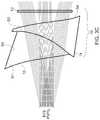
- FIG. 2schematically illustrates the unfolded optical path of an exemplary display system in accordance with the present invention
- FIG. 3Aschematically illustrates a 2D layout of virtual display optics of an exemplary display system in accordance with the present invention
- FIG. 3Bschematically illustrates a 2D layout of the exemplary display system of FIG. 3A but having a field lens comprising two optical elements rather than a singlet;
- FIG. 3Cschematically illustrates the free-form eyepiece and compensator of FIGS. 3A-3B showing the see-through optical path
- FIG. 3Dschematically illustrates the free-form eyepiece and compensator of FIGS. 3A-3B showing both the see-through and display paths;
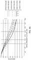
- FIGS. 4A-4Eillustrate the polychromatic MTF through the display path for the virtual display system of FIG. 3B ;
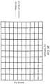
- FIG. 4Fillustrates a distortion grid through the display path for the virtual display system of FIG. 3B ;
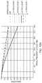
- FIGS. 5A-5Eillustrate the polychromatic MTF through the see-through path for the virtual display system of FIG. 3B ;
- FIG. 5Fillustrates a distortion grid through the see-through path for the virtual display system of FIG. 3B ;
- FIG. 6Aschematically illustrates a 3D layout of the free-form eyepiece with relay optics of the display system of FIG. 3B ;
- FIG. 6Bschematically illustrates a 3D Solidworks model of the assembled free-form eyepiece and compensator of the display system of FIG. 6A ;
- FIG. 7Aillustrates a depth-fused 6-focal-plane 3D scene of 40 degrees of field of view and 3 diopters of depth, captured through the eyepiece for a prototype built according to the design of FIG. 3B ;
- FIGS. 7B-7Cillustrate 6-focal-plane 3D scenes captured by a camera focused at 2 m and 30 cm, respectively, for a prototype built according to the design of FIG. 3B ;
- FIG. 8Aillustrates a retinal image MTF as a function of accommodations in a dual-focal-plane display, with two focal planes placed at 1.2D and 1.8D, respectively, and with a luminance ratio of 1:1;
- FIG. 8Billustrates a retinal image contrast as a function of accommodation showing the contrast gradient for different spatial frequencies
- FIGS. 9A-9Billustrate that the spatial frequency of a transition point decreases when the focal plane separation increases and when the eye pupil size increases, respectively;
- FIGS. 10A, 10Bschematically illustrate 2D and 3D layouts, respectively, of the virtual display optics of a further exemplary display system in accordance with the present invention
- FIG. 11schematically illustrates a 2D layout and element descriptions of the relay lens group of FIG. 10A along with an optional display illumination path;
- FIGS. 12A, 12Billustrate polychromatic MTF and field curves, respectively, of the system of FIGS. 10A-11 .
- FIG. 2schematically illustrates the first-order unfolded optical path of an exemplary optical system which is particularly suited for providing high imaging quality in depth-fused multi-focal-plane stereoscopic displays with addressable focus cues.
- FIGS. 3A, 3Bschematically illustrate particular designs according to the layout of FIG. 2 , with a first optical system 100 having a single field lens 18 , FIG. 3A , and an alternative system 200 having a two-element 17 , 19 field lens 18 , FIG. 3B .
- a single set of optics for a single viewer's eyeis illustrated, it is understood that in a final stereoscopic device, two such sets of optics will be provided, one for each eye.
- a relevant feature of the designsis the inclusion of a relay lens group 20 which relays the image from a microdisplay, such as a digital micro-mirror device (DMD) 60 , to the front of an eyepiece 12 .
- the relay lens group 20may include a traditional, non-deformable lens 21 and a reflective active optical element, such as a deformable membrane mirror 80 , FIG. 2 .
- the relay lens 21may include a pair of doublets 22 , 24 and lens 26 , FIGS. 3A, 3B .
- the deformable membrane mirror device (DMMD) 80may be placed at the focal plane of the relay lens 21 and may serve as the system stop. Together the lens 21 , FIG. 2 , (or lenses 22 , 24 , 26 , FIGS.
- the DMMD 80may provide a folded double-telecentric system particularly suited to depth-fused multi-focal-plane stereoscopic displays.
- An advantage of designing a double-telecentric relay 20is that the change of optical power on the DMMD 80 changes only the location of the intermediate image without changing the image magnification, so that the field of view of the system and the angular resolution in eye space remain constant, and so that the corresponding pixels on multiple focal planes overlap with each other one-to-one.
- the designs of FIGS. 3A, 3Bare well suited for a depth fusing technique without the need for correcting misaligned multiple focal images otherwise resulting from different image magnifications.
- the focus cue or accommodation range, ⁇ D accommodationwhich implies the depth range of the 3D volume the system can render, is determined by
- ⁇ ⁇ D accommodation⁇ eye 2 ⁇ 1 2 ⁇ ⁇ DMMD
- ⁇ eyeis the power of the eyepiece 12
- ⁇ 1is the power of the relay lens 21
- ⁇ DMMDdenotes the range of power by which the deformable mirror 80 can change.
- the above equationgives and the relationship between the focal length of the relay lens 20 and the eyepiece 12 . Since the eyepiece 12 will relay the system stop, i.e., the DMMD 80 , to form an exit pupil, the ratio between the size of the exit pupil D xp and the size of the DMMD 80 , is fixed once the desired accommodation range is determined:
- D XPD DMMD f 1 / f eye .
- a field lens 18may be added in front of the DMD display 60 to magnify the image.
- the display 60may be an emissive display, or maybe a reflective display that is illuminated through an illumination path.
- the magnification introduced by the field lens 18is
- Table 1lists the first-order system specifications for the designs of FIGS. 3A, 3B .
- the optical see-through capabilities of the systems 100 , 200may be realized by using beamsplitters to fold the virtual display optics (e.g., DMD 60 , field lens 18 , relay lens group 20 ) out of the way.
- the virtual display opticse.g., DMD 60 , field lens 18 , relay lens group 20
- the eyepiece 12 in the present designhas a short focal length, it was very difficult to design the system conventionally.
- the eyepiece 12was designed as a wedge-shaped free-form plastic lens.
- the free-form prism eyepiece 12may include three rotationally asymmetric surfaces, labeled as S 1 , S 2 , and S 3 , respectively.
- S 1 , S 2 , and S 3rotationally asymmetric surfaces
- FIG. 3Da ray from the intermediate image of the display 60 is first refracted by the surface S 3 . After two consecutive reflections by surfaces S 1 and S 2 , the ray is transmitted through the surface S 1 and reaches the exit (eye) pupil of the system.
- the surface S 1desirably satisfies the condition of total internal reflection for all rays reflected on the surface S 1 .
- the surface S 2 of the eyepiece 12may be coated as a half mirror in order to facilitate the optical see-through capability.
- a free-form compensator 14which may include two rotationally asymmetric surfaces, S 2 and S 4 , may be cemented to the eyepiece 12 to compensate for the aberrations and distortions introduced to the rays from the real-world scene when the two pieces 12 , 14 are combined together, FIG. 3C .
- an optional cylindrical lens 13may be included with the free-form compensator 14 to help minimize aberrations and distortion for the see-through path.
- MTF valueswere selected to evaluate the overall image sharpness. Since the virtual display system 100 was designed backwards from the eyepiece 12 to the display 60 , the goal was to have MTF values no less than 20% at spatial frequency of 36 lp/mm on the display 60 , which is the cut-off frequency for pixel size of 14 ⁇ m. The human eye has an angular resolution of 1 arcmin. Therefore the compensator 14 was optimized such that the MTF values at 30 cycles/degree are greater than 0.2 to minimize degradation of the real-world scene.
- Another important optical performance factor of the system 100 , 200was image distortion. In conventional system, distortion is regular and can be compensated easily electronically or computationally. However in systems with off-axis freeform optics, the distortion can be very large and irregular. Therefore the design of the systems 100 , 200 should have tight constraints on distortion sampled over the entire FOV. The distortion is especially important for the see-through optical path, because it can change the sizes and shapes of objects seen through the see-through view, thus greatly affecting 3D perception.
- the design of the systems 100 , 200involved two steps, the virtual display path and the optical see-through path.
- the freeform eyepiece 12was setup with the relay lens 20 and field lens 18 in CodeV and optimized together.
- the display performancewas balanced for fields sampled across the 40-degrees of FOV and across the desired accommodation range of 3 diopters.
- the freeform eyepiece 12was setup alone with the compensator 14 and the compensator's back surface S 4 was optimized for see-through performance.
- the see-through performancewas optimized for 60 degrees of field of view while emphasizing the central 40 degrees.
- a progressive optimization strategywas adopted in both steps by gradually increasing the number of variable surface coefficients of the freeform surfaces as the system performance improved.
- the freeform eyepiece and compensator surfaces S 1 , S 2 , S 3 , S 4were described by XY-polynomials to the 10 th order and prototyped by single-point diamond turning on PMMA.
- one of the field lenses elements, element 17was optimized, and a diffractive optical feature was added to correct for chromatic aberrations introduced by the freeform eyepiece 12 .
- All other lenses 19 , 22 , 24 , 26are all off-the-shelf components to reduce the prototyping costs.
- the polychromatic MTF values of the virtual displayare greater than 0.2 at 36 lp/mm across the 40 degrees of field of view with a central field value of 0.5, FIGS. 4A-4E .
- the virtual displayalso shows minimal distortion, FIG. 4F .
- the polychromatic MTF values of the see-through optical path, evaluated for 3 mm pupilare greater than 0.4 at 30 cycles/degree across the 40 degrees of field of view, FIGS. 5A-5E .
- the distortion of the see-through scenewas also very well corrected, FIG. 5F .
- the prescription for the particular design of FIG. 3Bis provided as follows.
- surfaces #2-#4specify the free-form eyepiece 12 .
- Surface #2 and #4represent the same physical surface and is also denoted as eyepiece surface S 1 .
- Surface #3is also denoted as eyepiece surface S 2
- Surface #5is also denoted as eyepiece surface S 3 .
- Surfaces #8-#15 and surfaces #17-#24are the same group of relay lenses 22 , 24 , 26 modeled in double path.
- the deformable mirror 80is modeled at Surface #16.
- Surfaces #25-#26model the beam splitter 16 at 45 degrees.
- Surfaces #27-#28represent the field lens element 17
- Surfaces #29-#30represent the field lens element 19 .
- surfaces #2 and #3are eyepiece surfaces 1 and 3, modeled the same as in the virtual display path.
- Surfaces #4, #5specify the free-form compensator 14 .
- Surface #4is, it an exact replica of Surface #3 (eyepiece surface S 3 ).
- XY Polyrefers to a surface which may be represented by the equation
- zis the sag of the free-form surface measured along the z-axis of a local x, y, z coordinate system
- cis the vertex curvature (CUY)
- ris the radial distance
- kis the conic constant
- C jis the coefficient for x m y n .
- Aspherein the Tables refers to an aspherical surface which may be represented by the equation
- zcr 2 1 + 1 - ( 1 + k ) ⁇ c 2 ⁇ r 2 + Ar 4 + Br 6 + Cr 8 + Dr 10 + Er 12 ,
- zis the sag of the surface measured along the z-axis of a local x, y, z coordinate system
- cis the vertex curvature
- ris the radial distance
- kis the conic constant
- a through Eare the 4th, 6th, 8th, 10th and 12th order deformation coefficients, respectively.
- both surfaces of the field lens element 17are aspheric surfaces.
- the surface prescriptions of second field lens element 17are provide in Table 10-Table 12.
- an optional cylindrical lens 13has been included with the free-form compensator 14 to help minimize aberrations and distortion.
- An alternative designis also provided without the cylindrical lens 13 , in which the virtual display path is the same as shown in FIG. 3B and Table 2.
- the only difference among the remaining surfaces of the see-through path in the absence of the cylindrical lens 13is the eyepiece/compensator surface S 2 (Surface #5 in the optical see-through path of Table 3).
- Surfaces #2 and #3are eyepiece surfaces S 1 and S 3 , modeled the same as in the virtual display path.
- Surfaces #4-5describe the free-form compensator 14 .
- Surface #4is a exact replica of Surface #3.
- a prototype of the multi-focal-plane display system 200 of FIG. 3Bwas built with off-the-shelf lenses and customized optics, 3D views of which are provided in FIGS. 6A, 6B .
- the system 200was folded to avoid conflicting with the viewer's head.
- Custom electronicswere also developed to control and synchronize the display images on the DMD 60 (LUXBEAM® 4500, VISITECH, Drammen, Norway.), the illumination of the LED (not shown), and focal-plane switching of the deformable mirror 80 (OKO® Technologies MMDM10-1-focus, Flexible Optical B.V., Rijswijk, Netherlands).
- a continuous 3D scenewas rendered which was composed of a slanted planar object and a green floor grid, both extending from 0 to 2.5 diopters.
- the scenewas decomposed onto 6 focal planes, placed at 3 diopter, 2.4 diopter, 1.8 diopter, 1.2 diopter, 0.6 diopter and 0 diopter, based on the targets' depth values, and a depth-fusing technique was used to blend the 6 focal planes into a smooth continuum.
- the whole 3D scenewas refreshed at about 60 Hz; thus, flickering was not visible.
- FIG. 7Ashows the actual 6-focal-plane scene as seen through the system; the image was sharp and had very low distortion. Without special algorithms, the pixels on different focal planes overlap and fuse smoothly due to the constant field of view design.
- the prototypewas demonstrated to be capable of rendering 6 or more focal planes of high quality, high resolution color images at a flickering-free speed. It also had very good optical see-through performance for augmented reality applications, and has the potentially to provide higher depth perception accuracy, higher stereoacuity, and lower user fatigue.
- the present inventionprovides an exemplary multi-focal-plane display system 300 combining high-speed display technologies, such as Liquid Crystal on Silicon (LCOS) and Ferroelectric Liquid Crystal On Silicon (FLCoS) and a high-speed active refractive optical element, such as an electrical tunable lens 380 .
- LCOSLiquid Crystal on Silicon
- FLCoSFerroelectric Liquid Crystal On Silicon
- the specific designis based on a 0.8′′ WXGA LCOS/FLCOS display 360 and a 10 mm aperture electrical tunable lens 380 (Optotune EL-10-30, Optotune AG, Dietikon, Switzerland.)).
- the tunable lens 380changes shape when electrical current flows through the lens 380 to produce a change in optical power.
- the Optotune lens 380has a response time of about 2.5 ms and therefore potentially can be used in multi-focal-plane displays.
- FIGS. 10A-11The final layout of the design is shown in FIGS. 10A-11 .
- a relay lens group(lenses 302 , 304 , 306 , 380 , 308 , 310 ) relays the image to a spherical mirror 318 , which acts as an eyepiece and forms a virtual image for a user.
- the mirror 318may be aspherical.
- a beamsplitter 316is used to enable see-through capability.
- the tunable lens 380may provide the system stop and the system may be telecentric to the microdisplay 360 due to the requirements of LCOS/FLCoS. Enough space is also given for an illumination beamsplitter 317 , FIG. 11 .
- the prescription of the system 300is provided in Table 19-Table 26. (In Table 19, surfaces #9-12 model the Optotune electric tunable lens 380 .)
- the performance of the systemis illustrated in FIGS. 12A, 12B .
- the present inventionrelates to new criteria for determining depth-fused display (DFD) system design parameters.
- the optical quality of a fused pixel in DFD displaysis quantified by the point spread function (PSF) of its retinal image, or, equivalently, by the modulation transfer function (MTF) which is characterized by the ratio of the contrast modulation of the retinal image to that of a sinusoidal object on the 3D display.
- PSFpoint spread function
- MTFmodulation transfer function
- the PSF of a fused pixel, PSF 12by two pixels on a pair of adjacent focal planes located at z 1 and z 2 , respectively, may be described as the weighted sum of the PSFs from the front and the back pixels as:
- PSF 12 ⁇ ( z )w 1 ⁇ ( z ) ⁇ PSF 1 ⁇ ( z , z 1 ) ⁇ ⁇ x , y ⁇ PSF 1 ⁇ ( z , z 1 ) ⁇ dxdy + w 2 ⁇ ( z ) ⁇ PSF 2 ⁇ ( z , z 2 ) ⁇ ⁇ x , y ⁇ PSF 2 ⁇ ( z , z 2 ) ⁇ dxdy , ( 1 )
- PSF 1 (z, z 1 ) and PSF 2 (z, z 2 )are the point spread functions of the front and back pixels when the eye is accommodated at distance z.
- the PSFs in Eq. (1)are normalized so that front and back pixels have the same luminance before calculating the weighted sum.
- the MTF of the displaycan then be calculated via Fourier Transform of PSF 12 (z).
- FIG. 8AAn example of the MTF plots of simulated retinal images of a dual-focal-plane DFD display is shown in FIG. 8A .
- the two focal planeswere placed at 1.2 diopters and 1.8 diopters, respectively, and the luminance ratio between the two focal planes was 1:1, indicating that the fused pixel was being simulated at the dioptric midpoint of the front and back focal planes, i.e., 1.5 diopters.
- an eye modelwas selected with a 3 mm pupil, with all residual aberrations removed.
- FIG. 8Ashows how the MTF of the retinal image changes as the eye accommodates at various positions between the two focal planes.
- FIG. 8Ashows how the MTF of the retinal image changes as the eye accommodates at various positions between the two focal planes.
- the contrast of the fused pixelis always highest when the eye is accommodated at or near the physical focal planes, meaning that the contrast gradient has the tendency to drive the accommodation away from the simulated pixel depth, therefore creating a conflict accommodation cue.
- FIGS. 9A, 9Bshow how the transition frequency varies as a function of focal plane separation and as a function of pupil size.
- FIG. 9Aassumes a 3 mm eye pupil
- FIG. 9Bassumes a constant focal plane separation of 0.6 diopters.
- the resultssuggest that the smaller the focal plane separation and the smaller the designed eye pupil size, the higher in frequency the transition point is. Therefore a critical criterion for designing a DFD display is that the focal plane separation and the display's working pupil size should be determined such that the contrast gradient reverse point is higher than the system's cut-off frequency to avoid presenting a conflicting accommodation cue to the viewer.
- a 0.6-diopter separation between adjacent focal planescan be considered adequate for a DFD display affording an angular resolution of 1.8 arc minutes per pixel (approximately a spatial frequency of 17 cpd) and luminance greater than 10 cd/m 2 .
- the stimulation of 10 cd/m 2 display luminanceleads to approximately a 3 mm eye pupil diameter.
- a 0.45-diopter spacing or smallerwould be desired for displays affording an angular resolution of 1 arc minute per pixel (i.e., 30 cpd). The smaller the angular resolution per pixel or the lower the image brightness, the smaller the required focal-plane separation would be.
Landscapes
- Physics & Mathematics (AREA)
- General Physics & Mathematics (AREA)
- Optics & Photonics (AREA)
- Engineering & Computer Science (AREA)
- Multimedia (AREA)
- Signal Processing (AREA)
- Lenses (AREA)
- Testing, Inspecting, Measuring Of Stereoscopic Televisions And Televisions (AREA)
- Stereoscopic And Panoramic Photography (AREA)
- Mechanical Light Control Or Optical Switches (AREA)
- Liquid Crystal (AREA)
- Details Of Television Scanning (AREA)
Abstract
Description
where Φeyeis the power of the
The system half field of view is then:
| TABLE 1 |
| First-order system specifications for virtual display. |
| Microdisplay | 0.7″ DMD, XGA resolution, 14 μm pixel |
| 0~1.2 diopters | |
| range | |
| 0~3 diopters | |
| Field of | 40° (32.5°H × 24.5°V) |
| Relay lens focal length, f1 | 43.9 mm |
| Eyepiece focal length, feye | 27.8 mm |
| 6 mm | |
Free Form Eyepiece and Compensator
| TABLE 2 |
| System prescription for virtual display path. |
| Element number | Surface | Refract | ||||
| used in FIG. | Surface No. | Type | Y Radius | Thickness | Material | Mode |
| 1 (Stop) | Sphere | Infinity | 0.000 | ||||
| 12, | 2 | XY Poly | −185.496 | 0.000 | Refract | ||
| 12, | 3 | XY Poly | −67.446 | 0.000 | Reflect | ||
| 12, | 4 | XY Poly | −185.496 | 0.000 | Reflect | ||
| 12, | 5 | XY Poly | −830.046 | 0.000 | |||
| 6 | Sphere | Infinity | 0.000 | ||||
| 7 | Sphere | Infinity | 53.933 | ||||
| 24 | 8 | Sphere | 435.850 | 4.000 | NSF10 | Refract | |
| 9 | Sphere | 36.730 | 12.070 | Refract | |||
| 10 | Sphere | −53.760 | 18.079 | ||||
| 22 | 11 | Sphere | 53.760 | 12.070 | Refract | ||
| 12 | Sphere | −36.730 | 4.000 | Refract | |||
| 13 | Sphere | −435.850 | 19.826 | ||||
| 26 | 14 | Sphere | Infinity | 2.000 | Refract | ||
| 15 | Sphere | 38.900 | 3.502 | ||||
| 80 | 16 | Sphere | −4000.000 | −3.502 | |||
| 26 | 17 | Sphere | 38.900 | −2.000 | Refract | ||
| 18 | Sphere | Infinity | −19.826 | ||||
| 22 | 19 | Sphere | −435.850 | −4.000 | Refract | ||
| 20 | Sphere | −36.730 | −12.070 | Refract | |||
| 21 | Sphere | 53.760 | −18.079 | ||||
| 24 | 22 | Sphere | −53.760 | −12.070 | NBAF10 | Refract | |
| 23 | Sphere | 36.730 | −4.000 | Refract | |||
| 24 | Sphere | 435.850 | −23.000 | ||||
| 16 | 25 | Sphere | Infinity | −1.600 | 471400.6541 | ||
| 26 | Sphere | Infinity | −10.513 | ||||
| 19 | 27 | Sphere | −46.700 | −6.500 | NBK7 | Refract | |
| 28 | Sphere | Infinity | −1.896 | ||||
| 17 | 29 | Asphere | −102.223 | −2.800 | Refract | ||
| 30 | Asphere | −61.641 | −7.655 | Refract | |||
System Prescription for Optical See-Through Path
| TABLE 3 |
| System prescription for see-through path. |
| Element number | Surface | Surface | X | Refract | |||
| used in FIG. | No. | Type | Y Radius | Radius | Thickness | Material | Mode |
| 1 (Stop) | Sphere | Infinity | Infinity | 0.000 | ||||
| 12, | 2 | XY Poly | −185.496 | −185.496 | 0.000 | Refract | ||
| 12, | 3 | XY Poly | −67.446 | −67.446 | 0.000 | Refract | ||
| 14, | 4 | XY Poly | −67.446 | −67.446 | 0.000 | Refract | ||
| 14, | 5 | XY Poly | −87.790 | −87.790 | 10.000 | |||
| 13 | 6 | Cylindrical | Infinity | −103.400 | 6.5 | Refract | ||
| 13 | 7 | Sphere | Infinity | Infinity | 0.000 | Refract | ||
where z is the sag of the free-form surface measured along the z-axis of a local x, y, z coordinate system, c is the vertex curvature (CUY), r is the radial distance, k is the conic constant, and Cjis the coefficient for xmyn. The term “Asphere” in the Tables refers to an aspherical surface which may be represented by the equation
where z is the sag of the surface measured along the z-axis of a local x, y, z coordinate system, c is the vertex curvature, r is the radial distance, k is the conic constant, A through E are the 4th, 6th, 8th, 10th and 12th order deformation coefficients, respectively.
| TABLE 4 |
| Optical surface prescription of |
| Y Radius | −1.854965E+02 | X**2 * Y**5 | −1.505674E−10 |
| Conic Constant | −2.497467E+01 | X * Y**6 | 0.000000E+00 |
| X | 0.000000E+00 | Y**7 | −4.419392E−11 |
| Y | 0.000000E+00 | X**8 | 4.236650E−10 |
| X**2 | −2.331157E−03 | X**7 * Y | 0.000000E+00 |
| X * Y | 0.000000E+00 | X**6 * Y**2 | −1.079269E−10 |
| Y**2 | 6.691726E−04 | X**5 * Y**3 | 0.000000E+00 |
| X**3 | 0.000000E+00 | X**4 * Y**4 | −1.678245E−10 |
| X**2 * Y | −1.066279E−04 | X**3 * Y**5 | 0.000000E+00 |
| X Y**2 | 0.000000E+00 | X**2 * Y**6 | 2.198604E−12 |
| Y**3 | −2.956368E−05 | X * Y**7 | 0.000000E+00 |
| X**4 | −1.554280E−06 | Y**8 | −2.415118E−12 |
| X**3 * Y | 0.000000E+00 | X**9 | 0.000000E+00 |
| X**2 * Y**2 | 1.107189E−06 | X**8 * Y | 4.113054E−12 |
| X * Y**3 | 0.000000E+00 | X**7 * Y**2 | 0.000000E+00 |
| Y**4 | 1.579876E−07 | X**6 * Y**3 | −1.805964E−12 |
| X**5 | 0.000000E+00 | X**5 * Y**4 | 0.000000E+00 |
| X**4 * Y | 1.789364E−07 | X**4 * Y**5 | 9.480632E−13 |
| X**3 * Y**2 | 0.000000E+00 | X**3 * Y**6 | 0.000000E+00 |
| X**2 * Y**3 | −2.609879E−07 | X**2 * Y**7 | 2.891726E−13 |
| X * Y**4 | 0.000000E+00 | X * Y**8 | 0.000000E+00 |
| Y**5 | −6.129549E−10 | Y**9 | −2.962804E−14 |
| X**6 | −3.316779E−08 | X**10 | −6.030361E−13 |
| X**5 * Y | 0.000000E+00 | X**9 * Y | 0.000000E+00 |
| X**4 * Y**2 | 9.498635E−09 | X**8 * Y**2 | −7.368710E−13 |
| X**3 * Y**3 | 0.000000E+00 | X**7 * Y**3 | 0.000000E+00 |
| X**2 * Y**4 | 9.042084E−09 | X**6 * Y**4 | 9.567750E−13 |
| X * Y**5 | 0.000000E+00 | X**5 * Y**5 | 0.000000E+00 |
| Y**6 | −4.013470E−10 | X**4 * Y**6 | 4.280494E−14 |
| X**7 | 0.000000E+00 | X**3 * Y**7 | 0.000000E+00 |
| X**6 * Y | −8.112755E−10 | X**2 * Y**8 | −7.143578E−15 |
| X**5 * Y**2 | 0.000000E+00 | X * Y**9 | 0.000000E+00 |
| X**4 * Y**3 | 1.251040E−09 | Y**10 | 3.858414E−15 |
| X**3 * Y**4 | 0.000000E+00 | N-Radius | 1.000000E+00 |
| TABLE 5 |
| Decenter of |
| Surface #1 of Table 2. |
| Y DECENTER | Z DECENTER | ALPHA TILT |
| 6.775E+00 | 2.773E+01 | 7.711E+00 |
| TABLE 6 |
| Optical surface prescription of |
| Y Radius | −6.744597E+01 | X**2 * Y**5 | −3.464751E−11 |
| Conic Constant | −1.258507E+00 | X * Y**6 | 0.000000E+00 |
| X | 0.000000E+00 | Y**7 | −8.246179E−12 |
| Y | 0.000000E+00 | X**8 | −2.087865E−11 |
| X**2 | −1.300207E−03 | X**7 * Y | 0.000000E+00 |
| X * Y | 0.000000E+00 | X**6 * Y**2 | 2.845323E−11 |
| Y**2 | 4.658585E−04 | X**5 * Y**3 | 0.000000E+00 |
| X**3 | 0.000000E+00 | X**4 * Y**4 | −5.043398E−12 |
| X**2 * Y | −1.758475E−05 | X**3 * Y**5 | 0.000000E+00 |
| X Y**2 | 0.000000E+00 | X**2 * Y**6 | 2.142939E−14 |
| Y**3 | −1.684923E−06 | X * Y**7 | 0.000000E+00 |
| X**4 | −1.463720E−06 | Y**8 | 1.607499E−12 |
| X**3 * Y | 0.000000E+00 | X**9 | 0.000000E+00 |
| X**2 * Y**2 | −1.108359E−06 | X**8 * Y | −1.922597E−12 |
| X * Y**3 | 0.000000E+00 | X**7 * Y**2 | 0.000000E+00 |
| Y**4 | −1.098749E−07 | X**6 * Y**3 | 1.100072E−13 |
| X**5 | 0.000000E+00 | X**5 * Y**4 | 0.000000E+00 |
| X**4 * Y | −7.146353E−08 | X**4 * Y**5 | −4.806130E−14 |
| X**3 * Y**2 | 0.000000E+00 | X**3 * Y**6 | 0.000000E+00 |
| X**2 * Y**3 | −1.150619E−08 | X**2 * Y**7 | −2.913177E−14 |
| X * Y**4 | 0.000000E+00 | X * Y**8 | 0.000000E+00 |
| Y**5 | 5.911371E−09 | Y**9 | 9.703717E−14 |
| X**6 | −5.406591E−10 | X**10 | 2.032150E−13 |
| X**5 * Y | 0.000000E+00 | X**9 * Y | 0.000000E+00 |
| X**4 * Y**2 | −1.767107E−09 | X**8 * Y**2 | −1.037107E−13 |
| X**3 * Y**3 | 0.000000E+00 | X**7 * Y**3 | 0.000000E+00 |
| X**2 * Y**4 | −7.415334E−10 | X**6 * Y**4 | 3.602862E−14 |
| X * Y**5 | 0.000000E+00 | X**5 * Y**5 | 0.000000E+00 |
| Y**6 | −5.442400E−10 | X**4 * Y**6 | −8.831469E−15 |
| X**7 | 0.000000E+00 | X**3 * Y**7 | 0.000000E+00 |
| X**6 * Y | 6.463414E−10 | X**2 * Y**8 | 2.178095E−15 |
| X**5 * Y**2 | 0.000000E+00 | X * Y**9 | 0.000000E+00 |
| X**4 * Y**3 | 1.421597E−10 | Y**10 | 1.784074E−15 |
| X**3 * Y**4 | 0.000000E+00 | N-Radius | 1.000000E+00 |
| TABLE 7 |
| Decenter of |
| Y DECENTER | Z DECENTER | ALPHA TILT |
| 1.329E+01 | 4.321E+01 | −8.856E+00 |
| TABLE 8 |
| Optical surface prescription of |
| Y Radius | −8.300457E+02 | X**2 * Y**5 | 4.051880E−08 |
| Conic Constant | −9.675799E+00 | X * Y**6 | 0.000000E+00 |
| X | 0.000000E+00 | Y**7 | −3.973293E−09 |
| Y | 0.000000E+00 | X**8 | −1.881791E−10 |
| X**2 | −1.798206E−04 | X**7 * Y | 0.000000E+00 |
| X * Y | 0.000000E+00 | X**6 * Y**2 | 5.519986E−09 |
| Y**2 | −2.606383E−03 | X**5 * Y**3 | 0.000000E+00 |
| X**3 | 0.000000E+00 | X**4 * Y**4 | 3.822268E−09 |
| X**2 * Y | −7.767146E−05 | X**3 * Y**5 | 0.000000E+00 |
| X Y**2 | 0.000000E+00 | X**2 * Y**6 | −3.024448E−09 |
| Y**3 | −8.958581E−05 | X * Y**7 | 0.000000E+00 |
| X**4 | 1.978414E−05 | Y**8 | 2.673713E−11 |
| X**3 * Y | 0.000000E+00 | X**9 | 0.000000E+00 |
| X**2 * Y**2 | 2.081156E−05 | X**8 * Y | 1.006915E−10 |
| X * Y**3 | 0.000000E+00 | X**7 * Y**2 | 0.000000E+00 |
| Y**4 | −1.073001E−06 | X**6 * Y**3 | −2.945084E−10 |
| X**5 | 0.000000E+00 | X**5 * Y**4 | 0.000000E+00 |
| X**4 * Y | 2.585164E−07 | X**4 * Y**5 | 5.958040E−10 |
| X**3 * Y**2 | 0.000000E+00 | X**3 * Y**6 | 0.000000E+00 |
| X**2 * Y**3 | −2.752516E−06 | X**2 * Y**7 | −3.211903E−10 |
| X * Y**4 | 0.000000E+00 | X * Y**8 | 0.000000E+00 |
| Y**5 | −1.470053E−06 | Y**9 | 2.296303E−11 |
| X**6 | −1.116386E−07 | X**10 | 5.221834E−12 |
| X**5 * Y | 0.000000E+00 | X**9 * Y | 0.000000E+00 |
| X**4 * Y**2 | −3.501439E−07 | X**8 * Y**2 | 1.135044E−11 |
| X**3 * Y**3 | 0.000000E+00 | X**7 * Y**3 | 0.000000E+00 |
| X**2 * Y**4 | 1.324057E−07 | X**6 * Y**4 | −1.050621E−10 |
| X * Y**5 | 0.000000E+00 | X**5 * Y**5 | 0.000000E+00 |
| Y**6 | −9.038017E−08 | X**4 * Y**6 | 5.624902E−11 |
| X**7 | 0.000000E+00 | X**3 * Y**7 | 0.000000E+00 |
| X**6 * Y | 3.397174E−10 | X**2 * Y**8 | 5.369592E−12 |
| X**5 * Y**2 | 0.000000E+00 | X * Y**9 | 0.000000E+00 |
| X**4 * Y**3 | −1.873966E−08 | Y**10 | 2.497657E−12 |
| X**3 * Y**4 | 0.000000E+00 | N-Radius | 1.000000E+00 |
| TABLE 9 |
| Decenter of |
| Y DECENTER | Z DECENTER | ALPHA TILT |
| .427E+01 | 3.347E+01 | 7.230E+01 |
ϕ=Ar2+Br4+Cr6+Dr8+Er10,
where ϕ is the phase function of the diffractive element, r is the radial distance, A through E are the 4th, 6th, 8th, 10th and 12th order phase coefficients, respectively. The surface prescriptions of second
| TABLE 10 |
| Surface Prescription for Surface #29 of Table 2. |
| Y Radius | 1.022230E+02 | |
| Conic Constant (K) | 1.091191E+01 | |
| 4th Order Coefficient (A) | 4.372314E−06 | |
| 6th Order Coefficient (B) | −6.940740E−08 | |
| 8th Order Coefficient (C) | 8.588869E−11 | |
| 10th Order Coefficient (D) | 2.348571E−14 | |
| 12th Order Coefficient (E) | −1.463306E−16 | |
| TABLE 11 |
| Diffractive Optical Element Phase Data for Surface #29 of Table 2. |
| Construction Wavelength (nm) | 525 | |
| R**2 (HCO C1) | −1.295858E−03 | |
| R**4 (HCO C2) | −3.879339E−07 | |
| R**6 (HCO C3) | 8.494999E−09 | |
| R**8 (HCO C4) | −1.771348E−13 | |
| R**10 (HCO C5) | −3.584229E−15 | |
| TABLE 12 |
| Surface Prescription for |
| Y Radius | 6.164108E+01 | |
| Conic Constant (K) | 9.828641E+00 | |
| 4th Order Coefficient (A) | 5.898651E−05 | |
| 6th Order Coefficient (B) | −2.951081E−07 | |
| 8th Order Coefficient (C) | −3.440910E−10 | |
| 10th Order Coefficient (D) | 1.785109E−13 | |
| 12th Order Coefficient (E) | 2.803121E−15 | |
| TABLE 13 |
| Optical surface prescription of |
| Y Radius | −8.779024E+01 | X**2 * Y**5 | −8.011955E−11 |
| Conic Constant | −7.055198E+00 | X * Y**6 | 0.000000E+00 |
| X | 0.000000E+00 | Y**7 | 3.606142E−11 |
| Y | 0.000000E+00 | X**8 | 3.208020E−11 |
| X**2 | −3.191225E−03 | X**7 * Y | 0.000000E+00 |
| X * Y | 0.000000E+00 | X**6 * Y**2 | −2.180416E−11 |
| Y**2 | 4.331992E−03 | X**5 * Y**3 | 0.000000E+00 |
| X**3 | 0.000000E+00 | X**4 * Y**4 | −3.616135E−11 |
| X**2 * Y | −9.609025E−05 | X**3 * Y**5 | 0.000000E+00 |
| X Y**2 | 0.000000E+00 | X**2 * Y**6 | −5.893434E−12 |
| Y**3 | −2.432809E−05 | X * Y**7 | 0.000000E+00 |
| X**4 | −2.955089E−06 | Y**8 | 3.081069E−12 |
| X**3 * Y | 0.000000E+00 | X**9 | 0.000000E+00 |
| X**2 * Y**2 | 2.096887E−07 | X**8 * Y | 1.267096E−12 |
| X * Y**3 | 0.000000E+00 | X**7 * Y**2 | 0.000000E+00 |
| Y**4 | −9.184356E−07 | X**6 * Y**3 | −1.848104E−12 |
| X**5 | 0.000000E+00 | X**5 * Y**4 | 0.000000E+00 |
| X**4 * Y | 3.707556E−08 | X**4 * Y**5 | 5.208420E−14 |
| X**3 * Y**2 | 0.000000E+00 | X**3 * Y**6 | 0.000000E+00 |
| X**2 * Y**3 | −1.535357E−07 | X**2 * Y**7 | 1.198597E−13 |
| X * Y**4 | 0.000000E+00 | X * Y**8 | 0.000000E+00 |
| Y**5 | −1.445904E−08 | Y**9 | −6.834914E−14 |
| X**6 | −4.440851E−09 | X**10 | −1.706677E−14 |
| X**5 * Y | 0.000000E+00 | X**9 * Y | 0.000000E+00 |
| X**4 * Y**2 | 1.686424E−09 | X**8 * Y**2 | −1.614840E−14 |
| X**3 * Y**3 | 0.000000E+00 | X**7 * Y**3 | 0.000000E+00 |
| X**2 * Y**4 | 6.770909E−09 | X**6 * Y**4 | 8.739087E−14 |
| X * Y**5 | 0.000000E+00 | X**5 * Y**5 | 0.000000E+00 |
| Y**6 | −3.713094E−10 | X**4 * Y**6 | 3.940903E−15 |
| X**7 | 0.000000E+00 | X**3 * Y**7 | 0.000000E+00 |
| X**6 * Y | −1.316067E−10 | X**2 * Y**8 | 5.435162E−15 |
| X**5 * Y**2 | 0.000000E+00 | X * Y**9 | 0.000000E+00 |
| X**4 * Y**3 | 7.924387E−10 | Y**10 | −2.259169E−15 |
| X**3 * Y**4 | 0.000000E+00 | N-Radius | 1.000000E+00 |
| TABLE 14 |
| Decenter of |
| Y DECENTER | Z DECENTER | ALPHA TILT |
| 3.358E+00 | 4.900E+01 | 6.765E+00 |
Alternative Exemplary Design without Cylindrical Lens
| TABLE 15 |
| Alternative eyepiece optics prescription without cylindrical lens. |
| Surface Type | Y Radius | X Radius | Thickness | Material | Refract Mode | ||
| Object | Sphere | Infinity | Infinity | −666.700 | Refract | ||
| 1 (Stop) | Sphere | Infinity | Infinity | 0.000 | |||
| 2 | XY Polynomial | −185.496 | −185.496 | 0.000 | Refract | ||
| 3 | XY Polynomial | −67.446 | −67.446 | 0.000 | Refract | ||
| 4 | XY Polynomial | −67.446 | −67.446 | 0.000 | Refract | ||
| 5 | XY Polynomial | −492.346 | −492.346 | 0.000 | Refract | ||
| Image | Sphere | Infinity | Infinity | 0.000 | Refract | ||
| TABLE 16 |
| Optical surface prescription of |
| Y Radius | −4.923462E+02 | X**2 * Y**5 | −1.476237E−10 |
| Conic Constant | 3.982960E+00 | X * Y**6 | 0.000000E+00 |
| X | 0.000000E+00 | Y**7 | 2.044705E−11 |
| Y | 0.000000E+00 | X**8 | 2.971746E−11 |
| X**2 | −3.001720E−03 | X**7 * Y | 0.000000E+00 |
| X * Y | 0.000000E+00 | X**6 * Y**2 | −6.199724E−12 |
| Y**2 | −5.233825E−04 | X**5 * Y**3 | 0.000000E+00 |
| X**3 | 0.000000E+00 | X**4 * Y**4 | −2.279723E−11 |
| X**2 * Y | −6.009699E−05 | X**3 * Y**5 | 0.000000E+00 |
| X Y**2 | 0.000000E+00 | X**2 * Y**6 | −1.041364E−12 |
| Y**3 | −2.244921E−05 | X * Y**7 | 0.000000E+00 |
| X**4 | −6.379076E−07 | Y**8 | 1.125487E−12 |
| X**3 * Y | 0.000000E+00 | X**9 | 0.000000E+00 |
| X**2 * Y**2 | 2.968752E−06 | X**8 * Y | 1.210373E−12 |
| X * Y**3 | 0.000000E+00 | X**7 * Y**2 | 0.000000E+00 |
| Y**4 | 3.771516E−07 | X**6 * Y**3 | −1.331110E−12 |
| X**5 | 0.000000E+00 | X**5 * Y**4 | 0.000000E+00 |
| X**4 * Y | 5.359865E−08 | X**4 * Y**5 | −9.781602E−14 |
| X**3 * Y**2 | 0.000000E+00 | X**3 * Y**6 | 0.000000E+00 |
| X**2 * Y**3 | −1.965407E−07 | X**2 * Y**7 | 4.515428E−13 |
| X * Y**4 | 0.000000E+00 | X * Y**8 | 0.000000E+00 |
| Y**5 | −7.301859E−09 | Y**9 | −5.050786E−14 |
| X**6 | −6.841269E−09 | X**10 | −1.058279E−14 |
| X**5 * Y | 0.000000E+00 | X**9 * Y | 0.000000E+00 |
| X**4 * Y**2 | −2.507411E−09 | X**8 * Y**2 | −2.975833E−14 |
| X**3 * Y**3 | 0.000000E+00 | X**7 * Y**3 | 0.000000E+00 |
| X**2 * Y**4 | 4.627014E−10 | X**6 * Y**4 | 6.309574E−14 |
| X * Y**5 | 0.000000E+00 | X**5 * Y**5 | 0.000000E+00 |
| Y**6 | −4.841692E−10 | X**4 * Y**6 | −1.214005E−15 |
| X**7 | 0.000000E+00 | X**3 * Y**7 | 0.000000E+00 |
| X**6 * Y | −3.343485E−10 | X**2 * Y**8 | 1.180350E−14 |
| X**5 * Y**2 | 0.000000E+00 | X * Y**9 | 0.000000E+00 |
| X**4 * Y**3 | 7.999315E−10 | Y**10 | −5.938353E−16 |
| X**3 * Y**4 | 0.000000E+00 | N-Radius | 1.000000E+00 |
| TABLE 17 |
| Decenter of |
| to Surface #1 of Table 15. |
| Y DECENTER | Z DECENTER | ALPHA TILT |
| 4.618E+00 | 4.853E+01 | 7.007E+00 |
Prototype of System of
| TABLE 18 |
| Design specification for tunable lens system. |
| Microdisplay | 0.8″ LCOS/FLCOS WXGA, 14 μm |
| Tunable Lens | |
| 10 mm aperture, 12 diopter focus range | |
| Virtual Display | 50° (43.6° H × 26.4° V) |
| Field of | |
| Pupil size | |
| 10 | |
| Eye Clearance | |
| 20 mm (accommodates low-profile glasses) | |
| Image Quality | MTF > 0.2 at 36 lp/mm (5 mm pupil) |
| (DMD space) | |
| Display Distortion | <2.0% |
| Virtual Image Distance | 33 cm~Infinity |
| f-number | 2.2 |
| TABLE 19 |
| Tunable lens system prescription. |
| Element number | Surface | Refract | ||||
| used in FIG. | Surface No. | Type | Y Radius | Thickness | Material | Mode |
| 1 (Stop) | Sphere | Infinity | 44.000 | ||||
| 2 | Sphere | Infinity | −24.000 | ||||
| 318 | 3 | Sphere | 68.000 | 34.000 | |||
| 316 | 4 | Sphere | Infinity | 17.371 | |||
| 310 | 5 | Asphere | −23.777 | 6.000 | Refract | ||
| 6 | Asphere | 363.193 | 0.100 | ||||
| 308 | 7 | Sphere | 39.587 | 6.000 | Refract | ||
| 8 | Sphere | −119.109 | 4.385 | ||||
| 380 | 9 | Sphere | Infinity | 0.500 | Refract | ||
| 380 | 10 | Sphere | Infinity | 4.377 | |||
| 380 | 11 | Sphere | 30.270 | 2.023 | ‘OL1024’ | ||
| 380 | 12 | Sphere | Infinity | 0.500 | Refract | ||
| 13 | Sphere | Infinity | 3.724 | ||||
| 306 | 14 | Asphere | −24.004 | 5.999 | Refract | ||
| 15 | Asphere | 27.079 | 0.251 | ||||
| 304 | 16 | Sphere | 38.710 | 5.944 | Refract | ||
| ZE48R | |||||||
| 17 | Sphere | −21.557 | 5.631 | ||||
| 302 | 18 | Asphere | 33.959 | 9.698 | Refract | ||
| ZE48R | |||||||
| 19 | Asphere | −21.555 | 29.000 | Refract | |||
| TABLE 20 |
| Surface Prescription for |
| Y Radius | −23.777 | |
| Conic Constant (K) | 2.040996E+00 | |
| 4th Order Coefficient (A) | 1.385342E−04 | |
| 6th Order Coefficient (B) | −1.022594E−06 | |
| 8th Order Coefficient (C) | 8.784855E−09 | |
| 10th Order Coefficient (D) | −2.891372E−11 | |
| TABLE 21 |
| Surface Prescription for |
| Y Radius | 363.193 | |
| Conic Constant (K) | −1.060606E+01 | |
| 4th Order Coefficient (A) | 6.247531E−05 | |
| 6th Order Coefficient (B) | −8.622953E−07 | |
| 8th Order Coefficient (C) | 9.037984E−09 | |
| 10th Order Coefficient (D) | −4.513968E−11 | |
| TABLE 22 |
| Surface Prescription for |
| Y Radius | −24.004 | |
| Conic Constant (K) | 2.609562E+00 | |
| 4th Order Coefficient (A) | −1.053175E−04 | |
| 6th Order Coefficient (B) | 3.126004E−07 | |
| 8th Order Coefficient (C) | −2.716200E−08 | |
| 10th Order Coefficient (D) | 2.112687E−10 | |
| TABLE 23 |
| Surface Prescription for |
| Y Radius | 27.079 | |
| Conic Constant (K) | −6.178694E+00 | |
| 4th Order Coefficient (A) | −1.075797E−05 | |
| 6th Order Coefficient (B) | −1.383769E−07 | |
| 8th Order Coefficient (C) | 4.641779E−10 | |
| 10th Order Coefficient (D) | 9.831856E−13 | |
| TABLE 24 |
| Surface Prescription for |
| Construction Wavelength (nm) | 589 | |
| R**2 (HCO C1) | −1.543448E−03 | |
| R**4 (HCO C2) | 7.864956E−06 | |
| R**6 (HCO C3) | −1.080042E−07 | |
| R**8 (HCO C4) | 1.272753E−09 | |
| R**10 (HCO C5) | −5.114979E−12 | |
| TABLE 25 |
| Surface Prescription for |
| Y Radius | 33.959 | |
| Conic Constant (K) | 2.310849E+00 | |
| 4th Order Coefficient (A) | 4.222932E−06 | |
| 6th Order Coefficient (B) | −2.501786E−08 | |
| 8th Order Coefficient (C) | 3.154900E−11 | |
| 10th Order Coefficient (D) | 2.517705E−13 | |
| TABLE 26 |
| Surface Prescription for |
| Y Radius | −21.555 | |
| Conic Constant (K) | −1.347355E+00 | |
| 4th Order Coefficient (A) | 1.944341E−05 | |
| 6th Order Coefficient (B) | 3.600425E−08 | |
| 8th Order Coefficient (C) | −1.998220E−11 | |
| 10th Order Coefficient (D) | 6.798072E−13 | |
Overall Design Considerations
where PSF1(z, z1) and PSF2(z, z2) are the point spread functions of the front and back pixels when the eye is accommodated at distance z. The PSFs in Eq. (1) are normalized so that front and back pixels have the same luminance before calculating the weighted sum. w1and w2are the depth-weighted fusing functions modulating the luminance of the front and back pixels and typically w1(z)+w2(z)=1 is enforced so that the total luminance of the fused image stays the same when the simulated depth changes. The MTF of the display can then be calculated via Fourier Transform of PSF12(z).
Claims (8)
Priority Applications (2)
| Application Number | Priority Date | Filing Date | Title |
|---|---|---|---|
| US16/519,790US10598946B2 (en) | 2012-10-18 | 2019-07-23 | Stereoscopic displays with addressable focus cues |
| US16/803,168US11347036B2 (en) | 2012-10-18 | 2020-02-27 | Stereoscopic displays with addressable focus cues |
Applications Claiming Priority (5)
| Application Number | Priority Date | Filing Date | Title |
|---|---|---|---|
| US201261795500P | 2012-10-18 | 2012-10-18 | |
| PCT/US2013/065422WO2014062912A1 (en) | 2012-10-18 | 2013-10-17 | Stereoscopic displays with addressable focus cues |
| US201514435328A | 2015-04-13 | 2015-04-13 | |
| US15/833,387US10394036B2 (en) | 2012-10-18 | 2017-12-06 | Stereoscopic displays with addressable focus cues |
| US16/519,790US10598946B2 (en) | 2012-10-18 | 2019-07-23 | Stereoscopic displays with addressable focus cues |
Related Parent Applications (1)
| Application Number | Title | Priority Date | Filing Date |
|---|---|---|---|
| US15/833,387ContinuationUS10394036B2 (en) | 2012-10-18 | 2017-12-06 | Stereoscopic displays with addressable focus cues |
Related Child Applications (1)
| Application Number | Title | Priority Date | Filing Date |
|---|---|---|---|
| US16/803,168ContinuationUS11347036B2 (en) | 2012-10-18 | 2020-02-27 | Stereoscopic displays with addressable focus cues |
Publications (2)
| Publication Number | Publication Date |
|---|---|
| US20190346686A1 US20190346686A1 (en) | 2019-11-14 |
| US10598946B2true US10598946B2 (en) | 2020-03-24 |
Family
ID=50488746
Family Applications (4)
| Application Number | Title | Priority Date | Filing Date |
|---|---|---|---|
| US14/435,328Active2033-10-24US9874760B2 (en) | 2012-10-18 | 2013-10-17 | Stereoscopic displays with addressable focus cues |
| US15/833,387ActiveUS10394036B2 (en) | 2012-10-18 | 2017-12-06 | Stereoscopic displays with addressable focus cues |
| US16/519,790ActiveUS10598946B2 (en) | 2012-10-18 | 2019-07-23 | Stereoscopic displays with addressable focus cues |
| US16/803,168Active2034-02-06US11347036B2 (en) | 2012-10-18 | 2020-02-27 | Stereoscopic displays with addressable focus cues |
Family Applications Before (2)
| Application Number | Title | Priority Date | Filing Date |
|---|---|---|---|
| US14/435,328Active2033-10-24US9874760B2 (en) | 2012-10-18 | 2013-10-17 | Stereoscopic displays with addressable focus cues |
| US15/833,387ActiveUS10394036B2 (en) | 2012-10-18 | 2017-12-06 | Stereoscopic displays with addressable focus cues |
Family Applications After (1)
| Application Number | Title | Priority Date | Filing Date |
|---|---|---|---|
| US16/803,168Active2034-02-06US11347036B2 (en) | 2012-10-18 | 2020-02-27 | Stereoscopic displays with addressable focus cues |
Country Status (11)
| Country | Link |
|---|---|
| US (4) | US9874760B2 (en) |
| EP (1) | EP2910022B1 (en) |
| JP (3) | JP6525880B2 (en) |
| KR (2) | KR102207298B1 (en) |
| CN (2) | CN110022472B (en) |
| AU (4) | AU2013331179B2 (en) |
| CA (2) | CA2885563C (en) |
| IL (3) | IL276021B2 (en) |
| IN (1) | IN2015DN02476A (en) |
| NZ (3) | NZ739225A (en) |
| WO (1) | WO2014062912A1 (en) |
Families Citing this family (66)
| Publication number | Priority date | Publication date | Assignee | Title |
|---|---|---|---|---|
| GB2468997A (en) | 2008-01-22 | 2010-09-29 | Univ Arizona State | Head-mounted projection display using reflective microdisplays |
| US9866826B2 (en) | 2014-11-25 | 2018-01-09 | Ricoh Company, Ltd. | Content-adaptive multi-focal display |
| US9865043B2 (en) | 2008-03-26 | 2018-01-09 | Ricoh Company, Ltd. | Adaptive image acquisition and display using multi-focal display |
| WO2010123934A1 (en) | 2009-04-20 | 2010-10-28 | The Arizona Board Of Regents On Behalf Of The University Of Arizona | Optical see-through free-form head-mounted display |
| US20110075257A1 (en) | 2009-09-14 | 2011-03-31 | The Arizona Board Of Regents On Behalf Of The University Of Arizona | 3-Dimensional electro-optical see-through displays |
| DE102017203492A1 (en)* | 2017-03-03 | 2018-09-06 | Witec Wissenschaftliche Instrumente Und Technologie Gmbh | Method and device for imaging a sample surface |
| EP2564259B1 (en) | 2010-04-30 | 2015-01-21 | Beijing Institute Of Technology | Wide angle and high resolution tiled head-mounted display device |
| US10156722B2 (en)* | 2010-12-24 | 2018-12-18 | Magic Leap, Inc. | Methods and systems for displaying stereoscopy with a freeform optical system with addressable focus for virtual and augmented reality |
| NZ627582A (en) | 2012-01-24 | 2016-11-25 | Univ Arizona State | Compact eye-tracked head-mounted display |
| CN110022472B (en) | 2012-10-18 | 2022-07-26 | 亚利桑那大学评议会 | Stereoscopic display with addressable focus cues |
| US9699433B2 (en) | 2013-01-24 | 2017-07-04 | Yuchen Zhou | Method and apparatus to produce re-focusable vision with detecting re-focusing event from human eye |
| WO2014144989A1 (en)* | 2013-03-15 | 2014-09-18 | Ostendo Technologies, Inc. | 3d light field displays and methods with improved viewing angle depth and resolution |
| US9857591B2 (en) | 2014-05-30 | 2018-01-02 | Magic Leap, Inc. | Methods and system for creating focal planes in virtual and augmented reality |
| US9915826B2 (en) | 2013-11-27 | 2018-03-13 | Magic Leap, Inc. | Virtual and augmented reality systems and methods having improved diffractive grating structures |
| EP4099274B1 (en) | 2014-01-31 | 2024-03-06 | Magic Leap, Inc. | Multi-focal display system and method |
| CN110376743B (en) | 2014-01-31 | 2022-03-04 | 奇跃公司 | Multi-focus display system and method |
| CA2941655C (en) | 2014-03-05 | 2021-03-09 | Arizona Board Of Regents On Behalf Of The University Of Arizona | Wearable 3d augmented reality display with variable focus and/or object recognition |
| AU2015266670B2 (en)* | 2014-05-30 | 2019-05-09 | Magic Leap, Inc. | Methods and systems for displaying stereoscopy with a freeform optical system with addressable focus for virtual and augmented reality |
| EP3149528B1 (en) | 2014-05-30 | 2023-06-07 | Magic Leap, Inc. | Methods and system for creating focal planes in virtual and augmented reality |
| US9864205B2 (en) | 2014-11-25 | 2018-01-09 | Ricoh Company, Ltd. | Multifocal display |
| IL310369A (en) | 2015-01-26 | 2024-03-01 | Magic Leap Inc | Virtual and augmented reality systems and methods with improved diffractive lattice structures |
| US10176961B2 (en) | 2015-02-09 | 2019-01-08 | The Arizona Board Of Regents On Behalf Of The University Of Arizona | Small portable night vision system |
| US9848127B2 (en)* | 2015-07-14 | 2017-12-19 | Honeywell International Inc. | System and method for a compact display |
| US10204451B2 (en)* | 2015-11-30 | 2019-02-12 | Microsoft Technology Licensing, Llc | Multi-optical surface optical design |
| US20210223738A1 (en)* | 2015-12-28 | 2021-07-22 | Seereal Technologies S.A. | Display device and method for optimizing the image quality |
| AU2017225977C1 (en) | 2016-03-04 | 2023-08-03 | Magic Leap, Inc. | Current drain reduction in AR/VR display systems |
| US10698215B2 (en) | 2016-03-25 | 2020-06-30 | Magic Leap, Inc. | Virtual and augmented reality systems and methods |
| US11067797B2 (en) | 2016-04-07 | 2021-07-20 | Magic Leap, Inc. | Systems and methods for augmented reality |
| CN105929537A (en)* | 2016-04-08 | 2016-09-07 | 北京骁龙科技有限公司 | Head-mounted display and eyepiece system thereof |
| EP3453171A4 (en)* | 2016-05-04 | 2019-12-18 | The Regents of the University of California | LIGHT PSEUDO-FIELD DISPLAY APPARATUS |
| WO2018052590A2 (en) | 2016-08-12 | 2018-03-22 | Arizona Board Of Regents On Behalf Of The University Of Arizona | High-resolution freeform eyepiece design with a large exit pupil |
| JP6964239B2 (en)* | 2016-08-31 | 2021-11-10 | パナソニックIpマネジメント株式会社 | Display device |
| RU2650086C1 (en) | 2016-12-22 | 2018-04-06 | Самсунг Электроникс Ко., Лтд. | Holographic image display device and a method of operation of a control unit contained in it |
| WO2018165123A1 (en)* | 2017-03-09 | 2018-09-13 | Arizona Board Of Regents On Behalf Of The University Of Arizona | Freeform prism and head-mounted display with increased field of view |
| US12078802B2 (en) | 2017-03-09 | 2024-09-03 | Arizona Board Of Regents On Behalf Of The University Of Arizona | Head-mounted light field display with integral imaging and relay optics |
| JP7182796B2 (en) | 2017-03-09 | 2022-12-05 | アリゾナ ボード オブ リージェンツ オン ビハーフ オブ ザ ユニバーシティ オブ アリゾナ | Head-mounted Lightfield Display Using Integral Imaging and Waveguide Prisms |
| CN110998412A (en)* | 2017-05-18 | 2020-04-10 | 代表亚利桑那大学的亚利桑那校董会 | Multi-layer high dynamic range head-mounted display |
| WO2019040484A1 (en)* | 2017-08-23 | 2019-02-28 | Pcms Holdings, Inc. | Light field image engine method and apparatus for generating projected 3d light fields |
| EP3704531B1 (en) | 2017-11-02 | 2023-12-06 | InterDigital Madison Patent Holdings, SAS | Method and system for aperture expansion in light field displays |
| WO2019116730A1 (en) | 2017-12-11 | 2019-06-20 | パナソニックIpマネジメント株式会社 | Head-up display and moving body with head-up display mounted thereon |
| EP3726276B1 (en) | 2017-12-11 | 2023-03-22 | Panasonic Intellectual Property Management Co., Ltd. | Head-up display and moving body with head-up display mounted thereon |
| CN109932806B (en)* | 2017-12-18 | 2021-06-08 | 中强光电股份有限公司 | Optical lens |
| CN109932820A (en)* | 2017-12-18 | 2019-06-25 | 中强光电股份有限公司 | monitor |
| CN107861247B (en)* | 2017-12-22 | 2020-08-25 | 联想(北京)有限公司 | Optical component and augmented reality device |
| JP7185331B2 (en) | 2018-03-22 | 2022-12-07 | アリゾナ ボード オブ リージェンツ オン ビハーフ オブ ザ ユニバーシティ オブ アリゾナ | How to render light field images for integral imaging light field displays |
| KR20190118846A (en) | 2018-04-11 | 2019-10-21 | 한국과학기술연구원 | Multi-focal augmented reality device |
| US10529117B2 (en)* | 2018-04-16 | 2020-01-07 | Facebook Technologies, Llc | Systems and methods for rendering optical distortion effects |
| US11966055B2 (en) | 2018-07-19 | 2024-04-23 | Magic Leap, Inc. | Content interaction driven by eye metrics |
| CN110618529A (en)* | 2018-09-17 | 2019-12-27 | 武汉美讯半导体有限公司 | Light field display system for augmented reality and augmented reality device |
| US20210396978A1 (en)* | 2018-11-09 | 2021-12-23 | Sony Group Corporation | Observation optical system and image display apparatus |
| US11698516B2 (en)* | 2018-11-27 | 2023-07-11 | National Taiwan University | Head mounted display device and near-eye light field display device thereof |
| CN111624767B (en)* | 2019-02-28 | 2022-03-04 | 京东方科技集团股份有限公司 | near-eye display device |
| US11852813B2 (en)* | 2019-04-12 | 2023-12-26 | Nvidia Corporation | Prescription augmented reality display |
| US11991343B2 (en) | 2019-06-07 | 2024-05-21 | Interdigital Madison Patent Holdings, Sas | Optical method and system for light field displays based on distributed apertures |
| JP7560499B2 (en) | 2019-06-28 | 2024-10-02 | ピーシーエムエス ホールディングス インコーポレイテッド | OPTICAL METHODS AND SYSTEMS FOR LIGHT FIELD (LF) DISPLAYS BASED ON A TUNABLE LIQUID CRYSTAL (LC) DIFFUSER - Patent application |
| JP7353625B2 (en) | 2019-09-06 | 2023-10-02 | 国立大学法人群馬大学 | volumetric display |
| US10989927B2 (en)* | 2019-09-19 | 2021-04-27 | Facebook Technologies, Llc | Image frame synchronization in a near eye display |
| KR102284743B1 (en)* | 2020-05-14 | 2021-08-03 | 한국과학기술연구원 | Extended dof image display apparatus and method for controlling thereof |
| CN112255809A (en)* | 2020-11-20 | 2021-01-22 | 浙江水晶光电科技股份有限公司 | Lens group and near-to-eye display device |
| JP7600756B2 (en)* | 2021-02-26 | 2024-12-17 | セイコーエプソン株式会社 | Optical unit and image display device |
| CN113341555B (en)* | 2021-08-02 | 2022-08-05 | 深圳纳德光学有限公司 | Reflective eyepiece optical system and head-mounted near-eye display device |
| CN113325566B (en)* | 2021-08-02 | 2022-08-05 | 深圳纳德光学有限公司 | Reflective eyepiece optical system and head-mounted near-to-eye display device |
| CN113341558B (en)* | 2021-08-02 | 2022-08-05 | 深圳纳德光学有限公司 | Reflective eyepiece optical system and head-mounted near-to-eye display device |
| KR20230043612A (en)* | 2021-09-24 | 2023-03-31 | 삼성전자주식회사 | See-through type display device and augmented reality apparatus including the same |
| CN116413911B (en)* | 2021-12-31 | 2025-08-01 | 北京耐德佳显示技术有限公司 | Ultra-thin lens, virtual image imaging device using same and near-eye display |
| US12028509B1 (en)* | 2023-12-04 | 2024-07-02 | Mloptic Corp. | Diffraction-limited optical target system with continuously-variable virtual distance |
Citations (142)
| Publication number | Priority date | Publication date | Assignee | Title |
|---|---|---|---|---|
| US3632184A (en) | 1970-03-02 | 1972-01-04 | Bell Telephone Labor Inc | Three-dimensional display |
| US3992084A (en) | 1973-05-11 | 1976-11-16 | Nippon Kogaku K.K. | Zoom lens system also capable of ultra-closeup photography |
| US4468101A (en) | 1981-05-29 | 1984-08-28 | Marconi Avionics Limited | Night vision goggles |
| US4669810A (en) | 1984-02-03 | 1987-06-02 | Flight Dynamics, Inc. | Head up display system |
| US4753522A (en) | 1985-06-03 | 1988-06-28 | Ricoh Company, Ltd. | Plastic lens assembly for use in copying machines |
| US4863251A (en) | 1987-03-13 | 1989-09-05 | Xerox Corporation | Double gauss lens for a raster input scanner |
| EP0408344A2 (en) | 1989-07-14 | 1991-01-16 | Gec-Marconi Limited | Helmet systems |
| US5109469A (en) | 1990-11-01 | 1992-04-28 | Itt Corporation | Phosphor screen for correcting luminous non-uniformity and method for making same |
| US5172275A (en) | 1990-12-14 | 1992-12-15 | Eastman Kodak Company | Apochromatic relay lens systems suitable for use in a high definition telecine apparatus |
| US5172272A (en) | 1989-12-25 | 1992-12-15 | Olympus Optical Co., Ltd. | Imaging lens system |
| US5416315A (en) | 1994-01-24 | 1995-05-16 | Night Vision General Partnership | Visor-mounted night vision visor |
| US5436763A (en) | 1992-04-07 | 1995-07-25 | Hughes Aircraft Company | Wide spectral bandwidth virtual image display optical system |
| US5526183A (en) | 1993-11-29 | 1996-06-11 | Hughes Electronics | Helmet visor display employing reflective, refractive and diffractive optical elements |
| JPH08160345A (en) | 1994-12-05 | 1996-06-21 | Olympus Optical Co Ltd | Head mounted display device |
| US5572229A (en) | 1991-04-22 | 1996-11-05 | Evans & Sutherland Computer Corp. | Head-mounted projection display system featuring beam splitter and method of making same |
| US5621572A (en) | 1994-08-24 | 1997-04-15 | Fergason; James L. | Optical system for a head mounted display using a retro-reflector and method of displaying an image |
| US5625495A (en) | 1994-12-07 | 1997-04-29 | U.S. Precision Lens Inc. | Telecentric lens systems for forming an image of an object composed of pixels |
| JPH09218375A (en) | 1996-02-08 | 1997-08-19 | Canon Inc | Fatigue determination method and observation device using the same |
| JPH09297282A (en) | 1996-05-01 | 1997-11-18 | Nippon Telegr & Teleph Corp <Ntt> | Head mounted display device |
| US5699194A (en) | 1996-02-13 | 1997-12-16 | Olympus Optical Co., Ltd. | Image display apparatus comprising an internally reflecting ocular optical system |
| US5701202A (en) | 1995-05-18 | 1997-12-23 | Olympus Optical Co., Ltd. | Head or face mounted image display apparatus |
| US5706136A (en) | 1995-02-28 | 1998-01-06 | Canon Kabushiki Kaisha | Optical system, and image observing apparatus and image pickup apparatus using it |
| JPH1013861A (en) | 1996-04-24 | 1998-01-16 | Sony Corp | Three-dimension image display method and its display device |
| US5818632A (en) | 1995-04-13 | 1998-10-06 | Melles Griot, Inc | Multi-element lens system |
| JPH10307263A (en) | 1997-05-07 | 1998-11-17 | Olympus Optical Co Ltd | Prism optical element and image observation device |
| US5880711A (en) | 1996-04-24 | 1999-03-09 | Sony Corporation | Three-dimensional image display method and its display apparatus |
| WO1999023647A1 (en) | 1997-11-05 | 1999-05-14 | Omd Devices, L.L.C. | Focus error correction apparatus |
| US5917656A (en) | 1996-11-05 | 1999-06-29 | Olympus Optical Co., Ltd. | Decentered optical system |
| US5959780A (en) | 1996-04-15 | 1999-09-28 | Olympus Optical Co., Ltd. | Head-mounted display apparatus comprising a rotationally asymmetric surface |
| JPH11326820A (en) | 1998-05-18 | 1999-11-26 | Olympus Optical Co Ltd | Observing optical system and observing device using it |
| US6008781A (en) | 1992-10-22 | 1999-12-28 | Board Of Regents Of The University Of Washington | Virtual retinal display |
| US6023373A (en) | 1998-03-26 | 2000-02-08 | Mixed Reality Systems Laboratory Inc. | Reflective image display apparatus |
| US6028606A (en) | 1996-08-02 | 2000-02-22 | The Board Of Trustees Of The Leland Stanford Junior University | Camera simulation system |
| US6034823A (en) | 1997-02-07 | 2000-03-07 | Olympus Optical Co., Ltd. | Decentered prism optical system |
| CN1252133A (en) | 1997-12-11 | 2000-05-03 | 皇家菲利浦电子有限公司 | Image display device and head-mounted display comprising same |
| JP2001013446A (en) | 1999-07-02 | 2001-01-19 | Olympus Optical Co Ltd | Observation optical system |
| US6198577B1 (en) | 1998-03-10 | 2001-03-06 | Glaxo Wellcome, Inc. | Doubly telecentric lens and imaging system for multiwell plates |
| US6201646B1 (en) | 1998-10-26 | 2001-03-13 | Olympus Optical Co., Ltd | Image-forming optical system and viewing optical system |
| JP2001066543A (en) | 1999-08-25 | 2001-03-16 | Canon Inc | Composite optical device |
| US6236521B1 (en) | 1998-02-09 | 2001-05-22 | Canon Kabushiki Kaisha | Objective lens and image pickup device using the same |
| EP1102105A1 (en) | 1999-11-19 | 2001-05-23 | Mixed Reality Systems Laboratory Inc. | Image display apparatus |
| JP2001145127A (en) | 1999-11-12 | 2001-05-25 | Shunichi Suda | Three-dimensional image display device |
| US6239915B1 (en) | 1998-08-26 | 2001-05-29 | Mixed Reality Systems Laboratory Inc. | Composite display apparatus |
| US6243199B1 (en) | 1999-09-07 | 2001-06-05 | Moxtek | Broad band wire grid polarizing beam splitter for use in the visible wavelength region |
| US20010009478A1 (en) | 1994-06-13 | 2001-07-26 | Shoichi Yamazaki | Head-up display device with rotationally asymmetric curved surface |
| JP2001238229A (en) | 2000-02-21 | 2001-08-31 | Nippon Hoso Kyokai <Nhk> | Stereoscopic image photographing device, stereoscopic image display device, and stereoscopic image photographing display system |
| US20020015116A1 (en) | 2000-07-31 | 2002-02-07 | Daeyang E&C Co., Ltd. | Optical system for head mounted display |
| JP2002148559A (en) | 2000-11-15 | 2002-05-22 | Mixed Reality Systems Laboratory Inc | Image observing device and image observing system using the device |
| US20020060850A1 (en) | 2000-09-22 | 2002-05-23 | Tetsuhide Takeyama | Observing optical system and imaging optical system |
| US6396639B1 (en) | 1999-02-04 | 2002-05-28 | Olympus Optical Co., Ltd. | Viewing optical system and image display apparatus using the same |
| US20020063913A1 (en) | 2000-09-29 | 2002-05-30 | Tohru Nakamura | Observation optical system using volume hologram |
| US20020067467A1 (en) | 2000-09-07 | 2002-06-06 | Dorval Rick K. | Volumetric three-dimensional display system |
| US6404562B1 (en) | 1999-05-20 | 2002-06-11 | Konica Corporation | Zoom lens |
| US6404561B1 (en) | 1999-10-29 | 2002-06-11 | Minolta Co., Ltd. | Taking lens apparatus |
| US6433760B1 (en) | 1999-01-14 | 2002-08-13 | University Of Central Florida | Head mounted display with eyetracking capability |
| US6433376B2 (en) | 1999-12-08 | 2002-08-13 | Dongbu Electronics Co., Ltd. | Ferroelectric memory integrated circuit |
| US6493146B2 (en) | 2000-08-09 | 2002-12-10 | Canon Kabushiki Kaisha | Image display apparatus |
| US6510006B1 (en) | 1998-12-07 | 2003-01-21 | Olympus Optical Co., Ltd. | Image-forming optical system |
| US20030076591A1 (en) | 1998-04-21 | 2003-04-24 | Shigeto Ohmori | Lens optical system |
| US6563648B2 (en) | 2000-10-20 | 2003-05-13 | Three-Five Systems, Inc. | Compact wide field of view imaging system |
| US20030090753A1 (en) | 2001-07-24 | 2003-05-15 | Olympus Optical Co., Ltd. | Optical system and device using the same |
| JP2003241100A (en) | 2002-02-18 | 2003-08-27 | Olympus Optical Co Ltd | Eccentric optical system |
| US6646811B2 (en) | 2001-03-01 | 2003-11-11 | Canon Kabushiki Kaisha | Optical element and compound display apparatus using the same |
| US6653989B2 (en) | 2001-02-21 | 2003-11-25 | Canon Kabushiki Kaisha | Composite display apparatus and head mounted display system using the same |
| US6671099B2 (en) | 2000-12-25 | 2003-12-30 | Olympus Optical Co., Ltd. | Image-forming optical system |
| US6731434B1 (en) | 2001-05-23 | 2004-05-04 | University Of Central Florida | Compact lens assembly for the teleportal augmented reality system |
| US20040136097A1 (en) | 2002-12-30 | 2004-07-15 | Samsung Techwin Co., Ltd. | Photographing lens |
| US20040164927A1 (en) | 1996-01-17 | 2004-08-26 | Nippon Telegraph And Telephone Corporation | Optical device and three-dimensional display device |
| WO2004079431A1 (en) | 2003-03-05 | 2004-09-16 | 3M Innovative Properties Company | Diffractive lens |
| US20040196213A1 (en) | 1998-11-09 | 2004-10-07 | University Of Washington | Scanned beam display with focal length adjustment |
| US20040218243A1 (en) | 2003-04-23 | 2004-11-04 | Shoichi Yamazaki | Scanning optical system |
| US20040233551A1 (en) | 1997-05-07 | 2004-11-25 | Olympus Corporation | Prism optical element, image observation apparatus and image display apparatus |
| US6829113B2 (en) | 1999-02-12 | 2004-12-07 | Olympus Corporation | Image-forming optical system |
| US20050036119A1 (en) | 2003-04-24 | 2005-02-17 | Ruda Mitchell C. | Solid state light engine optical system |
| US20050179868A1 (en) | 2004-02-13 | 2005-08-18 | Angstrom Inc. | Three-dimensional display using variable focusing lens |
| US6963454B1 (en) | 2002-03-01 | 2005-11-08 | Research Foundation Of The University Of Central Florida | Head-mounted display by integration of phase-conjugate material |
| US20050248849A1 (en) | 2004-04-23 | 2005-11-10 | Microvision, Inc. | Optical element that includes a microlens array and related method |
| US20060028400A1 (en) | 2004-08-03 | 2006-02-09 | Silverbrook Research Pty Ltd | Head mounted display with wave front modulator |
| US6999239B1 (en) | 2001-05-23 | 2006-02-14 | Research Foundation Of The University Of Central Florida, Inc | Head-mounted display by integration of phase-conjugate material |
| US20060119951A1 (en) | 2004-09-01 | 2006-06-08 | Mcguire James P Jr | Compact head mounted display devices with tilted/decentered lens element |
| JP2006276884A (en) | 2006-06-16 | 2006-10-12 | Olympus Corp | Eccentric prism optical system |
| WO2007002694A2 (en) | 2005-06-24 | 2007-01-04 | Texas Instruments Incorporated | Optical engine for projectors using led illumination |
| US7177083B2 (en) | 2003-02-17 | 2007-02-13 | Carl-Zeiss-Stiftung Trading As | Display device with electrooptical focussing |
| JP2007101930A (en) | 2005-10-05 | 2007-04-19 | Matsushita Electric Ind Co Ltd | 3D image element image creation and display method and 3D image display device |
| US20070109505A1 (en) | 2005-10-05 | 2007-05-17 | Matsushita Electric Industrial Co., Ltd. | Projection three-dimensional display apparatus |
| US7249853B2 (en) | 2005-04-13 | 2007-07-31 | Eastman Kodak Company | Unpolished optical element with periodic surface roughness |
| WO2007085682A1 (en) | 2006-01-26 | 2007-08-02 | Nokia Corporation | Eye tracker device |
| US20070246641A1 (en) | 2004-02-27 | 2007-10-25 | Baun Kenneth W | Night vision system with video screen |
| WO2007140273A2 (en) | 2006-05-26 | 2007-12-06 | Hebert Raymond T | Devices, methods and systems for image viewing |
| US20080036853A1 (en) | 2006-05-04 | 2008-02-14 | Samsung Electronics Co., Ltd. | High resolution autostereoscopic display apparatus with interlaced image |
| WO2008089417A2 (en) | 2007-01-18 | 2008-07-24 | The Arizona Board Of Regents On Behalf Of The University Of Arizona | A polarized head-mounted projection display |
| US7405881B2 (en) | 2005-05-30 | 2008-07-29 | Konica Minolta Holdings, Inc. | Image display apparatus and head mount display |
| US7414791B2 (en) | 2004-10-08 | 2008-08-19 | Canon Kabushiki Kaisha | Eye detection apparatus and image display apparatus |
| US20080291531A1 (en) | 2006-10-09 | 2008-11-27 | Heimer Richard J | Compact Objective Lens Assembly |
| CN101359089A (en) | 2008-10-08 | 2009-02-04 | 北京理工大学 | Optical system of light, small and large field of view free-form prism head-mounted display |
| US7522344B1 (en) | 2005-12-14 | 2009-04-21 | University Of Central Florida Research Foundation, Inc. | Projection-based head-mounted display with eye-tracking capabilities |
| CN101424788A (en) | 2008-12-09 | 2009-05-06 | 中国科学院长春光学精密机械与物理研究所 | Glasses type climbing helmet display optical system |
| US20090115842A1 (en) | 2007-11-02 | 2009-05-07 | Canon Kabushiki Kaisha | Image display apparatus |
| US20090168010A1 (en) | 2007-12-27 | 2009-07-02 | Igor Vinogradov | Adaptive focusing using liquid crystal lens in electro-optical readers |
| US20100091027A1 (en) | 2008-10-14 | 2010-04-15 | Canon Kabushiki Kaisha | Image processing apparatus and image processing method |
| US20100109977A1 (en) | 2008-10-31 | 2010-05-06 | Canon Kabushiki Kaisha | Image display apparatus |
| US20100208372A1 (en) | 2009-02-19 | 2010-08-19 | Drs Sensors & Targeting Systems, Inc. | Compact Objective Lens Assembly for Simultaneously Imaging Multiple Spectral Bands |
| US20100271698A1 (en) | 2009-04-24 | 2010-10-28 | David Kessler | Pupil-expanded volumetric display |
| US20100289970A1 (en) | 2008-01-29 | 2010-11-18 | Brother Kogyo Kabushiki Kaisha | Image display device using variable-focus lens at conjugate image plane |
| US20110037951A1 (en) | 2008-01-22 | 2011-02-17 | Hong Hua | Head-mounted projection display using reflective microdisplays |
| US20110043644A1 (en) | 2008-04-02 | 2011-02-24 | Esight Corp. | Apparatus and Method for a Dynamic "Region of Interest" in a Display System |
| US20110075257A1 (en) | 2009-09-14 | 2011-03-31 | The Arizona Board Of Regents On Behalf Of The University Of Arizona | 3-Dimensional electro-optical see-through displays |
| US20110090389A1 (en) | 2009-10-15 | 2011-04-21 | Canon Kabushiki Kaisha | Image-pickup display device having optical element provided with diffraction element portion |
| US20110221656A1 (en) | 2010-02-28 | 2011-09-15 | Osterhout Group, Inc. | Displayed content vision correction with electrically adjustable lens |
| WO2011134169A1 (en) | 2010-04-30 | 2011-11-03 | Beijing Institute Of Technology | Wide angle and high resolution tiled head-mounted display device |
| US20120013988A1 (en) | 2010-07-16 | 2012-01-19 | Hutchin Richard A | Head mounted display having a panoramic field of view |
| US20120019557A1 (en) | 2010-07-22 | 2012-01-26 | Sony Ericsson Mobile Communications Ab | Displaying augmented reality information |
| US20120050891A1 (en) | 2010-08-31 | 2012-03-01 | Fraunhofer-Gesellschaft Zur Foerderung Der Angewandten Forschung E.V. | Objective |
| US20120057129A1 (en) | 2009-05-27 | 2012-03-08 | Qinetiq Limited | Eye tracking apparatus |
| US20120081800A1 (en)* | 2009-04-20 | 2012-04-05 | Dewen Cheng | Optical see-through free-form head-mounted display |
| US20120113092A1 (en) | 2010-11-08 | 2012-05-10 | Avi Bar-Zeev | Automatic variable virtual focus for augmented reality displays |
| US20120160302A1 (en) | 2010-12-27 | 2012-06-28 | Jeffrey Michael Citron | Trough shaped fresnel reflector solar concentrator |
| US20120162549A1 (en) | 2010-12-24 | 2012-06-28 | Chunyu Gao | Ergonomic Head Mounted Display Device And Optical System |
| WO2012118573A1 (en) | 2011-02-28 | 2012-09-07 | Osterhout Group, Inc. | Light control in head mounted displays |
| US20120242697A1 (en) | 2010-02-28 | 2012-09-27 | Osterhout Group, Inc. | See-through near-eye display glasses with the optical assembly including absorptive polarizers or anti-reflective coatings to reduce stray light |
| US20130100524A1 (en) | 2011-10-19 | 2013-04-25 | Simon Magarill | Microdisplay-based head-up display system |
| US20130112705A1 (en) | 2010-07-16 | 2013-05-09 | Mcgill Technology Limited | Dispensing apparatus |
| US8467133B2 (en) | 2010-02-28 | 2013-06-18 | Osterhout Group, Inc. | See-through display with an optical assembly including a wedge-shaped illumination system |
| WO2013112705A1 (en) | 2012-01-24 | 2013-08-01 | The Arizona Board Of Regents On Behalf Of The University Of Arizona | Compact eye-tracked head-mounted display |
| US8503087B1 (en) | 2010-11-02 | 2013-08-06 | Google Inc. | Structured optical surface |
| US20130222896A1 (en) | 2012-02-24 | 2013-08-29 | Seiko Epson Corporation | Virtual image display apparatus |
| US20130258461A1 (en) | 2012-03-29 | 2013-10-03 | Fujitsu Limited | 3d display device and method |
| US20130286053A1 (en) | 2012-04-25 | 2013-10-31 | Rod G. Fleck | Direct view augmented reality eyeglass-type display |
| US20130285885A1 (en) | 2012-04-25 | 2013-10-31 | Andreas G. Nowatzyk | Head-mounted light-field display |
| US20130300634A1 (en) | 2012-05-09 | 2013-11-14 | Nokia Corporation | Method and apparatus for determining representations of displayed information based on focus distance |
| WO2014062912A1 (en) | 2012-10-18 | 2014-04-24 | The Arizona Board Of Regents On Behalf Of The University Of Arizona | Stereoscopic displays with addressable focus cues |
| US20140300869A1 (en) | 2013-04-09 | 2014-10-09 | Massachusetts Institute Of Technology | Methods and Apparatus for Light Field Projection |
| US20150168802A1 (en) | 2012-03-21 | 2015-06-18 | Microsoft Technology Licensing, Llc | Freeform-prism eyepiece with illumination waveguide |
| US20150208061A1 (en) | 2013-11-21 | 2015-07-23 | Chih-Ming Yang | Three-dimensional display device |
| US20150212321A1 (en) | 2012-08-10 | 2015-07-30 | Johnson Controls Gmbh | Laser scanning head-up display system for vehicles |
| WO2015134740A1 (en) | 2014-03-05 | 2015-09-11 | Arizona Board Of Regents On Behalf Of The University Of Arizona | Wearable 3d augmented reality display with variable focus and/or object recognition |
| US20150363978A1 (en) | 2013-01-15 | 2015-12-17 | The University Of North Carolina At Chapel Hill | Methods, systems, and computer readable media for generating an augmented scene display |
| WO2016033317A1 (en) | 2014-08-29 | 2016-03-03 | Arizona Board Of Regent On Behalf Of The University Of Arizona | Ultra-compact head-up displays based on freeform waveguide |
| US20160239985A1 (en) | 2015-02-17 | 2016-08-18 | Osterhout Group, Inc. | See-through computer display systems |
| US20160320620A1 (en) | 2013-12-19 | 2016-11-03 | The University Of North Carolina At Chapel Hill | Optical see-through near-eye display using point light source backlight |
| US20170202633A1 (en) | 2014-02-21 | 2017-07-20 | The University Of Akron | Imaging and display system for guiding medical interventions |
| US20180045949A1 (en) | 2016-08-12 | 2018-02-15 | Arizona Board Of Regents On Behalf Of The University Of Arizona | High-resolution freeform eyepiece design with a large exit pupil |
Family Cites Families (17)
| Publication number | Priority date | Publication date | Assignee | Title |
|---|---|---|---|---|
| US5880888A (en) | 1989-01-23 | 1999-03-09 | Hughes Aircraft Company | Helmet mounted display system |
| JP3359152B2 (en)* | 1994-05-13 | 2002-12-24 | キヤノン株式会社 | Display device |
| JP2000249974A (en) | 1999-03-02 | 2000-09-14 | Canon Inc | Display device and stereoscopic display device |
| US20010048561A1 (en) | 2000-08-24 | 2001-12-06 | Heacock Gregory L. | Virtual imaging system for small font text |
| JP2002031776A (en) | 2000-07-14 | 2002-01-31 | Canon Inc | Display device |
| US6529331B2 (en) | 2001-04-20 | 2003-03-04 | Johns Hopkins University | Head mounted display with full field of view and high resolution |
| JP4639721B2 (en) | 2004-09-22 | 2011-02-23 | 株式会社ニコン | 3D image display device |
| US20090295683A1 (en) | 2008-05-27 | 2009-12-03 | Randall Pugh | Head mounted display with variable focal length lens |
| JP5329882B2 (en) | 2008-09-17 | 2013-10-30 | パイオニア株式会社 | Display device |
| JP5603716B2 (en) | 2010-09-06 | 2014-10-08 | オリンパス株式会社 | PRISM OPTICAL SYSTEM, IMAGE DISPLAY DEVICE AND IMAGING DEVICE USING PRISM OPTICAL SYSTEM |
| US10156722B2 (en) | 2010-12-24 | 2018-12-18 | Magic Leap, Inc. | Methods and systems for displaying stereoscopy with a freeform optical system with addressable focus for virtual and augmented reality |
| US8754829B2 (en) | 2012-08-04 | 2014-06-17 | Paul Lapstun | Scanning light field camera and display |
| JP6019918B2 (en)* | 2012-08-17 | 2016-11-02 | セイコーエプソン株式会社 | Virtual image display device |
| KR20150054967A (en) | 2012-09-11 | 2015-05-20 | 매직 립, 인코포레이티드 | Ergonomic head mounted display device and optical system |
| WO2014144989A1 (en) | 2013-03-15 | 2014-09-18 | Ostendo Technologies, Inc. | 3d light field displays and methods with improved viewing angle depth and resolution |
| US9857591B2 (en) | 2014-05-30 | 2018-01-02 | Magic Leap, Inc. | Methods and system for creating focal planes in virtual and augmented reality |
| JP6264878B2 (en) | 2013-12-24 | 2018-01-24 | セイコーエプソン株式会社 | Light guide device, virtual image display device, and light guide device manufacturing method |
- 2013
- 2013-10-17CNCN201910196858.2Apatent/CN110022472B/enactiveActive
- 2013-10-17CACA2885563Apatent/CA2885563C/enactiveActive
- 2013-10-17CACA3102710Apatent/CA3102710A1/ennot_activeAbandoned
- 2013-10-17WOPCT/US2013/065422patent/WO2014062912A1/enactiveApplication Filing
- 2013-10-17CNCN201380054355.2Apatent/CN104756494B/enactiveActive
- 2013-10-17AUAU2013331179Apatent/AU2013331179B2/enactiveActive
- 2013-10-17NZNZ739225Apatent/NZ739225A/enunknown
- 2013-10-17USUS14/435,328patent/US9874760B2/enactiveActive
- 2013-10-17KRKR1020157010915Apatent/KR102207298B1/enactiveActive
- 2013-10-17ININ2476DEN2015patent/IN2015DN02476A/enunknown
- 2013-10-17NZNZ707127Apatent/NZ707127A/enunknown
- 2013-10-17KRKR1020217001775Apatent/KR102344903B1/enactiveActive
- 2013-10-17EPEP13847218.8Apatent/EP2910022B1/enactiveActive
- 2013-10-17JPJP2015537820Apatent/JP6525880B2/enactiveActive
- 2013-10-17ILIL276021Apatent/IL276021B2/enunknown
- 2013-10-17NZNZ747102Apatent/NZ747102A/enunknown
- 2015
- 2015-03-31ILIL238058Apatent/IL238058A/enactiveIP Right Grant
- 2017
- 2017-09-25AUAU2017232225Apatent/AU2017232225B2/enactiveActive
- 2017-11-28ILIL255981Apatent/IL255981B/enactiveIP Right Grant
- 2017-12-06USUS15/833,387patent/US10394036B2/enactiveActive
- 2019
- 2019-05-07JPJP2019087244Apatent/JP6796368B2/enactiveActive
- 2019-07-05AUAU2019204862Apatent/AU2019204862B9/enactiveActive
- 2019-07-23USUS16/519,790patent/US10598946B2/enactiveActive
- 2020
- 2020-02-27USUS16/803,168patent/US11347036B2/enactiveActive
- 2020-11-14JPJP2020189912Apatent/JP7213002B2/enactiveActive
- 2021
- 2021-08-16AUAU2021217992Apatent/AU2021217992A1/ennot_activeAbandoned
Patent Citations (162)
| Publication number | Priority date | Publication date | Assignee | Title |
|---|---|---|---|---|
| US3632184A (en) | 1970-03-02 | 1972-01-04 | Bell Telephone Labor Inc | Three-dimensional display |
| US3992084A (en) | 1973-05-11 | 1976-11-16 | Nippon Kogaku K.K. | Zoom lens system also capable of ultra-closeup photography |
| US4468101A (en) | 1981-05-29 | 1984-08-28 | Marconi Avionics Limited | Night vision goggles |
| US4669810A (en) | 1984-02-03 | 1987-06-02 | Flight Dynamics, Inc. | Head up display system |
| US4753522A (en) | 1985-06-03 | 1988-06-28 | Ricoh Company, Ltd. | Plastic lens assembly for use in copying machines |
| US4863251A (en) | 1987-03-13 | 1989-09-05 | Xerox Corporation | Double gauss lens for a raster input scanner |
| EP0408344A2 (en) | 1989-07-14 | 1991-01-16 | Gec-Marconi Limited | Helmet systems |
| US5172272A (en) | 1989-12-25 | 1992-12-15 | Olympus Optical Co., Ltd. | Imaging lens system |
| US5109469A (en) | 1990-11-01 | 1992-04-28 | Itt Corporation | Phosphor screen for correcting luminous non-uniformity and method for making same |
| US5172275A (en) | 1990-12-14 | 1992-12-15 | Eastman Kodak Company | Apochromatic relay lens systems suitable for use in a high definition telecine apparatus |
| US5572229A (en) | 1991-04-22 | 1996-11-05 | Evans & Sutherland Computer Corp. | Head-mounted projection display system featuring beam splitter and method of making same |
| US5436763A (en) | 1992-04-07 | 1995-07-25 | Hughes Aircraft Company | Wide spectral bandwidth virtual image display optical system |
| US6008781A (en) | 1992-10-22 | 1999-12-28 | Board Of Regents Of The University Of Washington | Virtual retinal display |
| US5526183A (en) | 1993-11-29 | 1996-06-11 | Hughes Electronics | Helmet visor display employing reflective, refractive and diffractive optical elements |
| US5416315A (en) | 1994-01-24 | 1995-05-16 | Night Vision General Partnership | Visor-mounted night vision visor |
| US20010009478A1 (en) | 1994-06-13 | 2001-07-26 | Shoichi Yamazaki | Head-up display device with rotationally asymmetric curved surface |
| US20080094720A1 (en) | 1994-06-13 | 2008-04-24 | Canon Kabushiki Kaisha | Display device |
| US5621572A (en) | 1994-08-24 | 1997-04-15 | Fergason; James L. | Optical system for a head mounted display using a retro-reflector and method of displaying an image |
| JPH08160345A (en) | 1994-12-05 | 1996-06-21 | Olympus Optical Co Ltd | Head mounted display device |
| US5625495A (en) | 1994-12-07 | 1997-04-29 | U.S. Precision Lens Inc. | Telecentric lens systems for forming an image of an object composed of pixels |
| US5706136A (en) | 1995-02-28 | 1998-01-06 | Canon Kabushiki Kaisha | Optical system, and image observing apparatus and image pickup apparatus using it |
| US5818632A (en) | 1995-04-13 | 1998-10-06 | Melles Griot, Inc | Multi-element lens system |
| US5701202A (en) | 1995-05-18 | 1997-12-23 | Olympus Optical Co., Ltd. | Head or face mounted image display apparatus |
| US20040164927A1 (en) | 1996-01-17 | 2004-08-26 | Nippon Telegraph And Telephone Corporation | Optical device and three-dimensional display device |
| JPH09218375A (en) | 1996-02-08 | 1997-08-19 | Canon Inc | Fatigue determination method and observation device using the same |
| US5699194A (en) | 1996-02-13 | 1997-12-16 | Olympus Optical Co., Ltd. | Image display apparatus comprising an internally reflecting ocular optical system |
| US5959780A (en) | 1996-04-15 | 1999-09-28 | Olympus Optical Co., Ltd. | Head-mounted display apparatus comprising a rotationally asymmetric surface |
| JPH1013861A (en) | 1996-04-24 | 1998-01-16 | Sony Corp | Three-dimension image display method and its display device |
| US5880711A (en) | 1996-04-24 | 1999-03-09 | Sony Corporation | Three-dimensional image display method and its display apparatus |
| JPH09297282A (en) | 1996-05-01 | 1997-11-18 | Nippon Telegr & Teleph Corp <Ntt> | Head mounted display device |
| US6028606A (en) | 1996-08-02 | 2000-02-22 | The Board Of Trustees Of The Leland Stanford Junior University | Camera simulation system |
| US5917656A (en) | 1996-11-05 | 1999-06-29 | Olympus Optical Co., Ltd. | Decentered optical system |
| US6034823A (en) | 1997-02-07 | 2000-03-07 | Olympus Optical Co., Ltd. | Decentered prism optical system |
| JPH10307263A (en) | 1997-05-07 | 1998-11-17 | Olympus Optical Co Ltd | Prism optical element and image observation device |
| US20040233551A1 (en) | 1997-05-07 | 2004-11-25 | Olympus Corporation | Prism optical element, image observation apparatus and image display apparatus |
| WO1999023647A1 (en) | 1997-11-05 | 1999-05-14 | Omd Devices, L.L.C. | Focus error correction apparatus |
| CN1252133A (en) | 1997-12-11 | 2000-05-03 | 皇家菲利浦电子有限公司 | Image display device and head-mounted display comprising same |
| US6236521B1 (en) | 1998-02-09 | 2001-05-22 | Canon Kabushiki Kaisha | Objective lens and image pickup device using the same |
| US6198577B1 (en) | 1998-03-10 | 2001-03-06 | Glaxo Wellcome, Inc. | Doubly telecentric lens and imaging system for multiwell plates |
| US6271972B1 (en) | 1998-03-10 | 2001-08-07 | Glaxo Wellcome, Inc. | Doubly telecentric lens and imaging system for multiwell plates |
| US6023373A (en) | 1998-03-26 | 2000-02-08 | Mixed Reality Systems Laboratory Inc. | Reflective image display apparatus |
| US20030076591A1 (en) | 1998-04-21 | 2003-04-24 | Shigeto Ohmori | Lens optical system |
| JPH11326820A (en) | 1998-05-18 | 1999-11-26 | Olympus Optical Co Ltd | Observing optical system and observing device using it |
| US6239915B1 (en) | 1998-08-26 | 2001-05-29 | Mixed Reality Systems Laboratory Inc. | Composite display apparatus |
| US6201646B1 (en) | 1998-10-26 | 2001-03-13 | Olympus Optical Co., Ltd | Image-forming optical system and viewing optical system |
| US7230583B2 (en) | 1998-11-09 | 2007-06-12 | University Of Washington | Scanned beam display with focal length adjustment |
| US20040196213A1 (en) | 1998-11-09 | 2004-10-07 | University Of Washington | Scanned beam display with focal length adjustment |
| US6510006B1 (en) | 1998-12-07 | 2003-01-21 | Olympus Optical Co., Ltd. | Image-forming optical system |
| US6433760B1 (en) | 1999-01-14 | 2002-08-13 | University Of Central Florida | Head mounted display with eyetracking capability |
| US6396639B1 (en) | 1999-02-04 | 2002-05-28 | Olympus Optical Co., Ltd. | Viewing optical system and image display apparatus using the same |
| US6829113B2 (en) | 1999-02-12 | 2004-12-07 | Olympus Corporation | Image-forming optical system |
| US6404562B1 (en) | 1999-05-20 | 2002-06-11 | Konica Corporation | Zoom lens |
| JP2001013446A (en) | 1999-07-02 | 2001-01-19 | Olympus Optical Co Ltd | Observation optical system |
| JP2001066543A (en) | 1999-08-25 | 2001-03-16 | Canon Inc | Composite optical device |
| US6243199B1 (en) | 1999-09-07 | 2001-06-05 | Moxtek | Broad band wire grid polarizing beam splitter for use in the visible wavelength region |
| US6404561B1 (en) | 1999-10-29 | 2002-06-11 | Minolta Co., Ltd. | Taking lens apparatus |
| JP2001145127A (en) | 1999-11-12 | 2001-05-25 | Shunichi Suda | Three-dimensional image display device |
| EP1102105A1 (en) | 1999-11-19 | 2001-05-23 | Mixed Reality Systems Laboratory Inc. | Image display apparatus |
| US6384983B1 (en) | 1999-11-19 | 2002-05-07 | Mixed Realty Systems Laboratory Inc. | Image display apparatus |
| US6433376B2 (en) | 1999-12-08 | 2002-08-13 | Dongbu Electronics Co., Ltd. | Ferroelectric memory integrated circuit |
| JP2001238229A (en) | 2000-02-21 | 2001-08-31 | Nippon Hoso Kyokai <Nhk> | Stereoscopic image photographing device, stereoscopic image display device, and stereoscopic image photographing display system |
| US20020015116A1 (en) | 2000-07-31 | 2002-02-07 | Daeyang E&C Co., Ltd. | Optical system for head mounted display |
| US6493146B2 (en) | 2000-08-09 | 2002-12-10 | Canon Kabushiki Kaisha | Image display apparatus |
| US20020067467A1 (en) | 2000-09-07 | 2002-06-06 | Dorval Rick K. | Volumetric three-dimensional display system |
| US20020060850A1 (en) | 2000-09-22 | 2002-05-23 | Tetsuhide Takeyama | Observing optical system and imaging optical system |
| US20020063913A1 (en) | 2000-09-29 | 2002-05-30 | Tohru Nakamura | Observation optical system using volume hologram |
| US6563648B2 (en) | 2000-10-20 | 2003-05-13 | Three-Five Systems, Inc. | Compact wide field of view imaging system |
| JP2002148559A (en) | 2000-11-15 | 2002-05-22 | Mixed Reality Systems Laboratory Inc | Image observing device and image observing system using the device |
| US6671099B2 (en) | 2000-12-25 | 2003-12-30 | Olympus Optical Co., Ltd. | Image-forming optical system |
| US6653989B2 (en) | 2001-02-21 | 2003-11-25 | Canon Kabushiki Kaisha | Composite display apparatus and head mounted display system using the same |
| US6646811B2 (en) | 2001-03-01 | 2003-11-11 | Canon Kabushiki Kaisha | Optical element and compound display apparatus using the same |
| US6731434B1 (en) | 2001-05-23 | 2004-05-04 | University Of Central Florida | Compact lens assembly for the teleportal augmented reality system |
| US6999239B1 (en) | 2001-05-23 | 2006-02-14 | Research Foundation Of The University Of Central Florida, Inc | Head-mounted display by integration of phase-conjugate material |
| US20030090753A1 (en) | 2001-07-24 | 2003-05-15 | Olympus Optical Co., Ltd. | Optical system and device using the same |
| JP2003241100A (en) | 2002-02-18 | 2003-08-27 | Olympus Optical Co Ltd | Eccentric optical system |
| US6963454B1 (en) | 2002-03-01 | 2005-11-08 | Research Foundation Of The University Of Central Florida | Head-mounted display by integration of phase-conjugate material |
| US20040136097A1 (en) | 2002-12-30 | 2004-07-15 | Samsung Techwin Co., Ltd. | Photographing lens |
| US7177083B2 (en) | 2003-02-17 | 2007-02-13 | Carl-Zeiss-Stiftung Trading As | Display device with electrooptical focussing |
| WO2004079431A1 (en) | 2003-03-05 | 2004-09-16 | 3M Innovative Properties Company | Diffractive lens |
| US20040218243A1 (en) | 2003-04-23 | 2004-11-04 | Shoichi Yamazaki | Scanning optical system |
| US20050036119A1 (en) | 2003-04-24 | 2005-02-17 | Ruda Mitchell C. | Solid state light engine optical system |
| US7152977B2 (en) | 2003-04-24 | 2006-12-26 | Qubic Light Corporation | Solid state light engine optical system |
| US20050179868A1 (en) | 2004-02-13 | 2005-08-18 | Angstrom Inc. | Three-dimensional display using variable focusing lens |
| US20070246641A1 (en) | 2004-02-27 | 2007-10-25 | Baun Kenneth W | Night vision system with video screen |
| US20050248849A1 (en) | 2004-04-23 | 2005-11-10 | Microvision, Inc. | Optical element that includes a microlens array and related method |
| US20060028400A1 (en) | 2004-08-03 | 2006-02-09 | Silverbrook Research Pty Ltd | Head mounted display with wave front modulator |
| US20060119951A1 (en) | 2004-09-01 | 2006-06-08 | Mcguire James P Jr | Compact head mounted display devices with tilted/decentered lens element |
| US7414791B2 (en) | 2004-10-08 | 2008-08-19 | Canon Kabushiki Kaisha | Eye detection apparatus and image display apparatus |
| US7249853B2 (en) | 2005-04-13 | 2007-07-31 | Eastman Kodak Company | Unpolished optical element with periodic surface roughness |
| US7405881B2 (en) | 2005-05-30 | 2008-07-29 | Konica Minolta Holdings, Inc. | Image display apparatus and head mount display |
| WO2007002694A3 (en) | 2005-06-24 | 2007-04-19 | Texas Instruments Inc | Optical engine for projectors using led illumination |
| WO2007002694A2 (en) | 2005-06-24 | 2007-01-04 | Texas Instruments Incorporated | Optical engine for projectors using led illumination |
| US20070109505A1 (en) | 2005-10-05 | 2007-05-17 | Matsushita Electric Industrial Co., Ltd. | Projection three-dimensional display apparatus |
| JP2007101930A (en) | 2005-10-05 | 2007-04-19 | Matsushita Electric Ind Co Ltd | 3D image element image creation and display method and 3D image display device |
| US7522344B1 (en) | 2005-12-14 | 2009-04-21 | University Of Central Florida Research Foundation, Inc. | Projection-based head-mounted display with eye-tracking capabilities |
| WO2007085682A1 (en) | 2006-01-26 | 2007-08-02 | Nokia Corporation | Eye tracker device |
| US20080036853A1 (en) | 2006-05-04 | 2008-02-14 | Samsung Electronics Co., Ltd. | High resolution autostereoscopic display apparatus with interlaced image |
| WO2007140273A2 (en) | 2006-05-26 | 2007-12-06 | Hebert Raymond T | Devices, methods and systems for image viewing |
| JP2006276884A (en) | 2006-06-16 | 2006-10-12 | Olympus Corp | Eccentric prism optical system |
| US20080291531A1 (en) | 2006-10-09 | 2008-11-27 | Heimer Richard J | Compact Objective Lens Assembly |
| WO2008089417A2 (en) | 2007-01-18 | 2008-07-24 | The Arizona Board Of Regents On Behalf Of The University Of Arizona | A polarized head-mounted projection display |
| US20090115842A1 (en) | 2007-11-02 | 2009-05-07 | Canon Kabushiki Kaisha | Image display apparatus |
| US20090168010A1 (en) | 2007-12-27 | 2009-07-02 | Igor Vinogradov | Adaptive focusing using liquid crystal lens in electro-optical readers |
| US8511827B2 (en) | 2008-01-22 | 2013-08-20 | The Arizona Board Of Regents On Behalf Of The University Of Arizona | Head-mounted projection display using reflective microdisplays |
| US9310591B2 (en) | 2008-01-22 | 2016-04-12 | The Arizona Board Of Regents On Behalf Of The University Of Arizona | Head-mounted projection display using reflective microdisplays |
| US20130329304A1 (en) | 2008-01-22 | 2013-12-12 | The Arizona Board Of Regents On Behalf Of The University Of Arizona | Head-mounted projection display using reflective microdisplays |
| US20110037951A1 (en) | 2008-01-22 | 2011-02-17 | Hong Hua | Head-mounted projection display using reflective microdisplays |
| US20100289970A1 (en) | 2008-01-29 | 2010-11-18 | Brother Kogyo Kabushiki Kaisha | Image display device using variable-focus lens at conjugate image plane |
| US20110043644A1 (en) | 2008-04-02 | 2011-02-24 | Esight Corp. | Apparatus and Method for a Dynamic "Region of Interest" in a Display System |
| CN101359089A (en) | 2008-10-08 | 2009-02-04 | 北京理工大学 | Optical system of light, small and large field of view free-form prism head-mounted display |
| US20100091027A1 (en) | 2008-10-14 | 2010-04-15 | Canon Kabushiki Kaisha | Image processing apparatus and image processing method |
| US20100109977A1 (en) | 2008-10-31 | 2010-05-06 | Canon Kabushiki Kaisha | Image display apparatus |
| CN101424788A (en) | 2008-12-09 | 2009-05-06 | 中国科学院长春光学精密机械与物理研究所 | Glasses type climbing helmet display optical system |
| US20100208372A1 (en) | 2009-02-19 | 2010-08-19 | Drs Sensors & Targeting Systems, Inc. | Compact Objective Lens Assembly for Simultaneously Imaging Multiple Spectral Bands |
| US20120081800A1 (en)* | 2009-04-20 | 2012-04-05 | Dewen Cheng | Optical see-through free-form head-mounted display |
| US20140009845A1 (en) | 2009-04-20 | 2014-01-09 | Dewen Cheng | Optical see-through free-form head-mounted display |
| US9239453B2 (en) | 2009-04-20 | 2016-01-19 | Beijing Institute Of Technology | Optical see-through free-form head-mounted display |
| US20160085075A1 (en) | 2009-04-20 | 2016-03-24 | The Arizona Board Of Regents On Behalf Of The University Of Arizona | Optical see-through free-form head-mounted display |
| US20100271698A1 (en) | 2009-04-24 | 2010-10-28 | David Kessler | Pupil-expanded volumetric display |
| US20120057129A1 (en) | 2009-05-27 | 2012-03-08 | Qinetiq Limited | Eye tracking apparatus |
| US20110075257A1 (en) | 2009-09-14 | 2011-03-31 | The Arizona Board Of Regents On Behalf Of The University Of Arizona | 3-Dimensional electro-optical see-through displays |
| US20110090389A1 (en) | 2009-10-15 | 2011-04-21 | Canon Kabushiki Kaisha | Image-pickup display device having optical element provided with diffraction element portion |
| US20110221656A1 (en) | 2010-02-28 | 2011-09-15 | Osterhout Group, Inc. | Displayed content vision correction with electrically adjustable lens |
| US8467133B2 (en) | 2010-02-28 | 2013-06-18 | Osterhout Group, Inc. | See-through display with an optical assembly including a wedge-shaped illumination system |
| US20120242697A1 (en) | 2010-02-28 | 2012-09-27 | Osterhout Group, Inc. | See-through near-eye display glasses with the optical assembly including absorptive polarizers or anti-reflective coatings to reduce stray light |
| WO2011134169A1 (en) | 2010-04-30 | 2011-11-03 | Beijing Institute Of Technology | Wide angle and high resolution tiled head-mounted display device |
| US20130187836A1 (en) | 2010-04-30 | 2013-07-25 | Dewen Cheng | Wide angle and high resolution tiled head-mounted display device |
| US20130112705A1 (en) | 2010-07-16 | 2013-05-09 | Mcgill Technology Limited | Dispensing apparatus |
| US20120013988A1 (en) | 2010-07-16 | 2012-01-19 | Hutchin Richard A | Head mounted display having a panoramic field of view |
| US20120019557A1 (en) | 2010-07-22 | 2012-01-26 | Sony Ericsson Mobile Communications Ab | Displaying augmented reality information |
| US20120050891A1 (en) | 2010-08-31 | 2012-03-01 | Fraunhofer-Gesellschaft Zur Foerderung Der Angewandten Forschung E.V. | Objective |
| US8503087B1 (en) | 2010-11-02 | 2013-08-06 | Google Inc. | Structured optical surface |
| WO2012064546A1 (en) | 2010-11-08 | 2012-05-18 | Microsoft Corporation | Automatic variable virtual focus for augmented reality displays |
| US20120113092A1 (en) | 2010-11-08 | 2012-05-10 | Avi Bar-Zeev | Automatic variable virtual focus for augmented reality displays |
| JP2014505381A (en) | 2010-11-08 | 2014-02-27 | マイクロソフト コーポレーション | Automatic variable virtual focus for augmented reality display |
| US20120162549A1 (en) | 2010-12-24 | 2012-06-28 | Chunyu Gao | Ergonomic Head Mounted Display Device And Optical System |
| US20120160302A1 (en) | 2010-12-27 | 2012-06-28 | Jeffrey Michael Citron | Trough shaped fresnel reflector solar concentrator |
| WO2012118573A1 (en) | 2011-02-28 | 2012-09-07 | Osterhout Group, Inc. | Light control in head mounted displays |
| US20130100524A1 (en) | 2011-10-19 | 2013-04-25 | Simon Magarill | Microdisplay-based head-up display system |
| US20140361957A1 (en) | 2012-01-24 | 2014-12-11 | The Arizonia Board Of Regents On Behalf Of The University Of Arizonz | Compact eye-tracked head-mounted display |
| WO2013112705A1 (en) | 2012-01-24 | 2013-08-01 | The Arizona Board Of Regents On Behalf Of The University Of Arizona | Compact eye-tracked head-mounted display |
| US9720232B2 (en) | 2012-01-24 | 2017-08-01 | The Arizona Board Of Regents On Behalf Of The University Of Arizona | Compact eye-tracked head-mounted display |
| US20130222896A1 (en) | 2012-02-24 | 2013-08-29 | Seiko Epson Corporation | Virtual image display apparatus |
| US20150168802A1 (en) | 2012-03-21 | 2015-06-18 | Microsoft Technology Licensing, Llc | Freeform-prism eyepiece with illumination waveguide |
| US20130258461A1 (en) | 2012-03-29 | 2013-10-03 | Fujitsu Limited | 3d display device and method |
| US20130285885A1 (en) | 2012-04-25 | 2013-10-31 | Andreas G. Nowatzyk | Head-mounted light-field display |
| US20130286053A1 (en) | 2012-04-25 | 2013-10-31 | Rod G. Fleck | Direct view augmented reality eyeglass-type display |
| US20130300634A1 (en) | 2012-05-09 | 2013-11-14 | Nokia Corporation | Method and apparatus for determining representations of displayed information based on focus distance |
| US20150212321A1 (en) | 2012-08-10 | 2015-07-30 | Johnson Controls Gmbh | Laser scanning head-up display system for vehicles |
| WO2014062912A1 (en) | 2012-10-18 | 2014-04-24 | The Arizona Board Of Regents On Behalf Of The University Of Arizona | Stereoscopic displays with addressable focus cues |
| US9874760B2 (en) | 2012-10-18 | 2018-01-23 | Arizona Board Of Regents On Behalf Of The University Of Arizona | Stereoscopic displays with addressable focus cues |
| US20150277129A1 (en) | 2012-10-18 | 2015-10-01 | The Arizona Board Of Regents On Behalf Of The University Of Arizona | Stereoscopic displays with addressable focus cues |
| US20150363978A1 (en) | 2013-01-15 | 2015-12-17 | The University Of North Carolina At Chapel Hill | Methods, systems, and computer readable media for generating an augmented scene display |
| US20140300869A1 (en) | 2013-04-09 | 2014-10-09 | Massachusetts Institute Of Technology | Methods and Apparatus for Light Field Projection |
| US20150208061A1 (en) | 2013-11-21 | 2015-07-23 | Chih-Ming Yang | Three-dimensional display device |
| US20160320620A1 (en) | 2013-12-19 | 2016-11-03 | The University Of North Carolina At Chapel Hill | Optical see-through near-eye display using point light source backlight |
| US20170202633A1 (en) | 2014-02-21 | 2017-07-20 | The University Of Akron | Imaging and display system for guiding medical interventions |
| WO2015134740A1 (en) | 2014-03-05 | 2015-09-11 | Arizona Board Of Regents On Behalf Of The University Of Arizona | Wearable 3d augmented reality display with variable focus and/or object recognition |
| WO2016033317A1 (en) | 2014-08-29 | 2016-03-03 | Arizona Board Of Regent On Behalf Of The University Of Arizona | Ultra-compact head-up displays based on freeform waveguide |
| US20160239985A1 (en) | 2015-02-17 | 2016-08-18 | Osterhout Group, Inc. | See-through computer display systems |
| US20180045949A1 (en) | 2016-08-12 | 2018-02-15 | Arizona Board Of Regents On Behalf Of The University Of Arizona | High-resolution freeform eyepiece design with a large exit pupil |
| WO2018052590A2 (en) | 2016-08-12 | 2018-03-22 | Arizona Board Of Regents On Behalf Of The University Of Arizona | High-resolution freeform eyepiece design with a large exit pupil |
Non-Patent Citations (180)
| Title |
|---|
| ‘Fresnel Lenses’ downloaded from http://www.fresneltech.com on Jun. 8, 2011. Copyright Fresnel Technologies, Inc., 2003. |
| "OLED-XL Microdisplays," eMagin 5 pages (2010). |
| A. Castro, Y. Frauel, and B. Javidi, "Integral imaging with large depth of field using an asymmetric phase mask," Journal of Optics Express, vol. 15, Issue 16, pp. 10266-10273 (Aug. 2007). |
| A. Jones, I. McDowall, Yamada H., M. Bolas, P. Debevec, Rendering for an Interactive 360° Light Field Display ACM Transactions on Graphics (TOG)—Proceedings of ACM SIGGRAPH 2007, 26(3), 2007. |
| A. Malmone, and H. Fuchs, "Computational augmented reality eyeglasses," Proc. of ISMAR 2012. |
| A. T. Duchowski, "Incorporating the viewer's Point-Of-Regard (POR) in gaze-contingent virtual environments", SPIE-Int. Soc. Opt. Eng. Proceedings of Spie—the International Society for Optical Engineering, vol. 3295, 1998, pp. 332-343. |
| A. Yabe, "Representation of freeform surface suitable for optimization," Applied Optics, 2012. |
| Akeley et al., "A Stereo Display Prototype with Multiple Focal Distances," ACM Trans. Graphics 23:804-813 (2004). |
| Armitage, David, Ian Underwood, and Shin-Tson Wu. Introduction to Microdisplays. Chichester, England: Wiley, 2006. |
| Azuma, R., et al., ‘Recent advances in augmented reality’, IEEE Computer Graphics App;. 21, 34-47 (2001). |
| B. T. Schowengerdt, M. Murari, E. J. Seibel, "Volumetric display using scanned fiber array," SID Symposium Digest of Technical Papers, 2010. |
| Bajura, M., et al., "Merging virtual objects with the real world: seeing ultrasound imagery within the patient" in Proceedings of ACM SIGGRAPH (ACM, Chicago, 1992), pp. 203-210. |
| Biocca, et al., "Virtual eyes can rearrange your body: adapting to visual displacement in see-through, head-mounted displays", Presence: Teleoperators and Virtual Environments 7, 262-277 (1998). |
| Blundell, B. G., and Schwarz, A. J., "The classification of volumetric display systems: characteristics and predictability of the image space," IEEE Transaction on Visualization and Computer Graphics, 8(1), pp. 66-75, 2002. |
| Bunkenburg, J. ‘Innovative Diffractive Eyepiece for Helmet-Mounted Display.’ SPIE vol. 3430. pp. 41-49 Jul. 1998. |
| C. B. Burckhardt, "Optimum parameters and resolution limitation of integral photography," J. Opt. Soc. Am. 58, 71-76 (1968). |
| C. Curatu, H. Hua, and J. P. Rolland, "Projection-based headmounted display with eye-tracking capabilities," Proc. SPIE 5875, 587050J (2005). |
| C. Manh Do, R. Mart□ nez-Cuenca, and B. Javidi, "Three-dimensional object-distortion-tolerant recognition for integral imaging using independent component analysis," Journal of Optical Society of America A 26, issue 2, pp. 245-251 (Feb. 1, 2009). |
| Cakmakci, O., et al., ‘Head-Worn Displays: A Review’. Journal of Display Technology, vol. 2, No. 3, Sep. 2006, pp. 199-216. |
| Caudell, T., et al., "Augmented reality: an application of heads-up display technology to manual manufacturing processes" in Proceedings of Hawaii International Conferences on Systems Sciences (Hawaii, 1992), pp. 659-669. |
| Chih-Wei Chen, Myungjin Cho, Yi-Pai Huang, and Bahram Javidi, "Improved viewing zones for projection type integral imaging 3D display using adaptive liquid crystal prism array," IEEE Journal of Display Technology, 2014. |
| Christopher M. Bishop, Neural Networks for Pattern Recognition, Oxford University Press, Inc. New York, NY 1995. |
| Cruz-Neira et al., ‘Surround-Screen Projection-Based Virtual Reality: the Design and Implementation of the CAVE,’ Proceedings of the 20th Annual Conference on Computer Graphics and Interactive Techniques pp. 135-142, ACM SIGGRAPH, ACM Press (1993). |
| Curatu, C., J.P. Rolland, and Hong Hua, "Dual purpose lens for an eye-tracked projection head-mounted display," Proceedings of International Optical Design Conference, Vancouver, Canada, Jun. 2006. |
| D. Cheng, Y. Wang, H. Hua, and M. M. Talha, "Design of an optical see-through head-mounted display with a low f-number and large field of view using a freeform prism," Appl. Opt., 48(14):2655-2668, 2009. |
| D. Cheng, Y. Wang, H. Hua, J. Sasian, "Design of a wide-angle, lightweight head-mounted display using free-form optics tiling," Opt. Lett., 36(11):2098-100, 2011. |
| D. Cheng, Y.Wang, H. Hua, and M. M. Talha, Design of an optical see-through headmounted display with a low f-number and large field of view using a free-form prism, App. Opt. 48 (14), pp. 2655-2668, 2009. |
| D.M. Hoffman, A.R. Girshick, K. Akeley, and M.S. Banks, "Vergence-Accommodation Conflicts Hinder Visual Performance and Cause Visual Fatigue," J. Vision, 8(3), 1-30, (2008). |
| Davis et al., "Accommodation to Large Disparity Stereograms," Journal of AAPOS 6:377-384 (2002). |
| Dewen Cheng et al.; "Large field-of-view and high resolution free-form head-mounted display"; SPIE-OSA/ vol. 7652 Jun. 2018. |
| Downing et al., "A Three-Color, Solid-State, Three-Dimensional Display," Science 273:1185-1189 (1996). |
| Duchowski, A., "Eyetracking Methodology: theory and practice," Publisher: Springer, 2003. |
| Duchowski, A.T., and A. Coltekin, "Foveated gaze-contingent displays for peripheral LOD management, 3D visualization, and stereo imaging," ACM Trans. on Mult. Comp., Comm., and App. 3, 1-21, (2007). |
| Edgar et al., "Visual Accommodation Problems with Head-Up and Helmet-Mounted Displays?," Displays 15:68-75 (1994). |
| European Search Report dated Apr. 28, 2016 from EP application 13847218.8. |
| European Search Report dated Aug. 14, 2015 in corresponding EP application 13740989.2. |
| Examination Report dated Apr. 29, 2011 from corresponding GB Application No. GB1012165.5. |
| F. Okano, H. Hoshino, J. Arai y I. Yuyama, "Real-time pickup method for a three-dimensional image based on integral photography," Appl. Opt. 36, 1598-1603 (1997). |
| Favalora et al., "100 Million-Voxel Volumetric Display," Proc. SPIE 4712:300-312 (2002). |
| Full Certified Translation of Reference JP008160345. |
| G. Lippmann, "Epreuves reversibles donnant la sensation du relief," Journal of Physics (Paris) 7, 821-825 (1908). |
| G. Wetzstein et al., "Tensor Displays: Compressive light field synthesis using multilayer displays with directional backlighting," ACM Transactions on Graphics, 31(4), 2012. |
| GB Examination Report corresponding to GB 1012165.5 dated Jun. 28, 2011. |
| Geisler, W.S., J.S. Perry and J. Najemnik, "Visual search: The role of peripheral information measured using gaze-contingent displays," J. Vision 6, 858-873 (2006). |
| Graham-Rowe, "Liquid Lenses Make a Splash," Nature-Photonics pp. 2-4 (2006). |
| H. Hoshi, N. Taniguchi, H. Morishima, T. Akiyama, S. Yamazaki and A. Okuyama, "Off-axial HMD optical system consisting of aspherical surfaces without rotational symmetry," SPIE vol. 2653, 234 (1996). |
| H. Hua and B. Javidi, "A 3D integral imaging optical see-through head-mounted display", Optics Express, 22(11): 13484-13491, 2014. |
| H. Hua and C. Gao, "A polarized head-mounted projective display," in Proceedings of IEEE and ACM International Symposium on Mixed and Augmented Reality 2005 (IEEE, 2005), pp. 32-35. |
| H. Hua, "Sunglass-like displays become a reality with freeform optical technology," SPIE Newsroom, 2012. |
| H. Hua, C. Gao, and J. P. Rolland, ‘Study of the Imaging properties of retroreflective materials used in head-mounted projective displays (HMPDs),’ Proc. SPIE4711, 194-201 (2002). |
| H. Hua, C. Gao, F. Biocca, and J. P. Rolland, "An ultra-light and compact design and implementation of head-mounted projective displays," in Proceedings of IEEE VR 2001, pp. 175-182. |
| H. Hua, C. Pansing, and J.P. Rolland, "Modeling of an eye-imaging system for optimizing illumination schemes in an eye-tracked head-mounted display," Appl. Opt., 46(31):7757-75, Oct. 2007. |
| H. Hua, L. Brown, and C. Gao, "A new collaborative infrastructure: SCAPE," in Proceedings of IEEE VR 2003 (IEEE, 2003), pp. 171-179. |
| H. Hua, L. Brown, and C. Gao, "SCAPE: supporting stereoscopic collaboration in augmented and projective environments," IEEE Comput. Graphics Appl. 24, 66-75 (2004). |
| H. Hua, L. Brown, and C. Gao, "System and interface framework for SCAPE as a collaborative infrastructure," Presence: Teleoperators and Virtual Environments 13, 234-250 (2004). |
| H. Hua, P. Krishnaswamy, and J.P. Rolland, ‘Video-based eyetracking methods and algorithms in head-mounted displays,’ Opt. Express, 14(10):4328-50, May 2006. |
| H. Hua, X. Hu, and C. Gao, "A high-resolution optical see-through head-mounted display with eyetracking capability," Optics Express, Nov. 2013. |
| H. Hua, Y. Ha, and J. P. Rolland, ‘Design of an ultra-light and compact projection lens,’0 Appl. Opt. 42, 1-12 (2003), pp. 97-107. |
| H. Hua., A. Girardot, C. Gao. J. P. Rolland. ‘Engineering of head-mounted projective displays’. Applied Optics. 39 (22), pp. 3814-3824. (2000). |
| H. Mukawa, K. Akutsu, I. Matsumura, S. Nakano, T. Yoshida, M. Kuwahara, and K. Aiki, A full-color eyewear display using planar waveguides with reflection volume holograms, J. Soc. Inf. Display 19 (3), pp. 185-193, 2009. |
| Heanue et al., "Volume Holographic Storage and Retrieval of Digital Data," Science 265:749-752 (1994). |
| Hidenori Kuriyabashi, Munekazu Date, Shiro Suyama, Toyohiko HatadaJ. of the SID 14/5, 2006 pp. 493-498. |
| Hoshi, et al, "Off-axial HMD optical system consisting of aspherical surfaces without rotational symmetry," Proc. SPIE 2653, Stereoscopic Displays and Virtual Reality Systems III, 234 (Apr. 10, 1996). |
| Hu and Hua, "Design and tolerance of a freeform optical system for an optical see-through multi-focal plane display," Applied Optics, 2015. |
| Hu, X., Development of the Depth-Fused Multi-Focal Plane Display Technology, Ph.D. Dissertation, College of Optical Sciences, University of Arizona, 2014. |
| Hua et al, "Compact eyetracked optical see-through head-mounted display", Proc. SPIE 8288, Stereoscopic Displays and Applications XXIII, 82881F (Feb. 9, 2012). |
| Hua et al., ‘Design of a Bright Polarized Head-Mounted Projection Display’ Applied Optics 46:2600-2610 (2007). |
| Hua, "Merging the Worlds of Atoms and Bits: Augmented Virtual Environments," Optics and Photonics News 17:26-33 (2006). |
| Hua, H. "Integration of eye tracking capability into optical see-through head-mounted displays," Proceedings of SPIE (Electronic Imaging 2001), pp. 496-503, Jan. 2001. |
| Hua, H., C. Pansing, and J. P. Rolland, "Modeling of an eye-imaging system for optimizing illumination schemes in an eye-tracked head-mounted display," Applied Optics, 46(32): 1-14, Nov. 2007. |
| Inoue et al., "Accommodative Responses to Stereoscopic Three-Dimensional Display," Applied Optics, 36:4509-4515 (1997). |
| International Search Report and Written Opinion dated Nov. 24, 2015 in corresponding PCT application PCT/US2015/047163. |
| International Search Report dated Feb. 10, 2011 from PCT/CN2010/072376. |
| International Search Report dated Jan. 29, 2014 in corresponding international application PCT/ US2013/065422. |
| International Search Report dated Jun. 18, 2010 in corresponding international application PCT/US2010/031799. |
| International Search Report dated Mar. 9, 2009 with regard to International Patent Application No. PCT/ US2009/031606. |
| J. Arai, et al., "Depth-control method for integral imaging," Feb. 1, 2008 / vol. 33, No. 3 / Optics Letters. |
| J. E. Melzer's: ‘Overcoming the field-of-view/resolution invariant in head-mounted displays’ Proc. SPIE vol. 3362, 1998, p. 284. |
| J. G. Droessler, D. J. Rotier, "Tilted cat helmet-mounted display," Opt. Eng., vol. 29, 849 (1990). |
| J. Hong, S. Min, and B. Lee, "Integral floating display systems for augmented reality," Applixed Optics, 51(18):4201-9, 2012. |
| J. L. Pezzaniti and R. A. Chipman, "Angular dependence of polarizing beam-splitter cubes," Appl. Opt. 33, 1916-1929 (1994). |
| J. P. Rolland and Hong Hua. "Head-mounted display systems," in Encyclopedia of Optical Engineering. R. Barry Johnson and Ronald O. Driggers, Eds, (2005). |
| J. P. Rolland, "Wide-angle, off-axis, see-through head-mounted display," Opt. Eng., vol. 39, 1760 (2000). |
| J. P. Rolland, F. Biocca, F. Hamza-Lup, Y. Ha, and R. Martins, "Development of head-mounted projection displays for distributed, collaborative, augmented reality applications," Presence: Teleoperators and Virtual Environments 14, 528-549 (2005). |
| J. S. Jang and B. Javidi, "Large depth-of-focus time-multiplexed three-dimensional integral imaging by use of lenslets with non-uniform focal lengths and aperture sizes," Opt. Lett. vol. 28, pp. 1924-1926 (2003). |
| J. S. Jang, F. Jin, and B. Javidi, "Three-dimensional integral imaging with large depth of focus by use of real and virtual image fields," Opt. Lett. 28:1421-23, 2003. |
| J. Y. Son, W.H. Son, S.K. Kim, K.H. Lee, B. Javidi, "Three-Dimensional Imaging for Creating Real-World-Like Environments," Proceedings of IEEE Journal, vol. 101, issue 1, pp. 190-205, Jan. 2013. |
| Jisoo Hong, et al., "Three-dimensional display technologies of recent interest: Principles, Status, and Issues," Applied Optics (Dec. 1, 2011) 50(34):106. |
| Jisoo Hong, et al., "Three-dimensional display technologies of recent interest: Principles, Status, and Issues," Applied Optics (Dec. 1, 2011) 50(34):106. (Year: 2011).* |
| K. Iwamoto, K. Tanie, T. T. Maeda, "A head-mounted eye movement tracking display and its image display method", Systems & Computers in Japan, vol. 28, No. 7, 30 Jun. 1997, pp. 89-99. Publisher: Scripta Technica, USA. |
| K. Iwamoto, S. Katsumata, K. Tanie, "An eye movement tracking type head mounted display for virtual reality system:—evaluation experiments of a prototype system", Proceedings of 1994 IEEE International Conference on Systems, Man, and Cybernetics. Humans, Information and Technology (Cat. No. 94CH3571-5). IEEE. Part vol. 1, 1994, pp. 13-18 vol. 1. New York, NY, USA. |
| K. Ukai and P.A. Howardth, "Visual fatigue caused by viewing stereoscopic motion images: background, theories, and observations," Displays, 29(2), pp. 106-116, 2008. |
| Krueerke, Daniel, "Speed May Give Ferroelectric LCOS Edge in Projection Race," Display Devices Fall '05. Copyright 2005 Dempa Publications, Inc. pp. 29-31. |
| Kuiper et al., "Variable-Focus Liquid Lens for Miniature Cameras," Applied Physics Letters 85:1128-1130 (2004). |
| Kuribayashi, et al., "A Method for Reproducing Apparent Continuous Depth in a Stereoscopic Display Using "Depth-Fused 3D" Technology" Journal of the Society for Information Display 14:493-498 (2006). |
| L. Brown and H. Hua, "Magic lenses for augmented virtual environments," IEEE Comput. Graphics Appl. 26, 64-73 (2006). |
| L. Davis, J. P. Rolland, F. Hamza-Lup, Y. Ha, J. Norfleet, and C. Imielinska, ‘Enabling a continuum of virtual environment experiences,’ IEEE Comput. Graphics Appl. 23, pp. 10-12 Mar./Apr. 2003. |
| L. G. Brown's: ‘Applications of the Sensics panoramic HMD’ SID Symposium Digest vol. 39, 2008, p. 77. |
| Laurence R. Young, David Sheena, "Survey of eye movement recording methods", Behavior Research Methods & Instrumentation, 7(5), 397-429, 1975. |
| Liu et al., ‘A Novel Prototype for an Optical See-Through Head-Mounted Display with Addressable Focus Cues,’ IEEE Transactions on Visualization and Computer Graphics 16:381-393 (2010). |
| Liu et al., "A Systematic Method for Designing Depth-Fused Multi-Focal Plane Three-Dimensional Displays," Optics Express 18:11562-11573 (2010). |
| Liu et al., "An Optical See-Through head Mounted Display with Addressable Focal Planes," IEEE Computer Society, pp. 33-42 (2008). |
| Liu et al., "Time-Multiplexed Dual-Focal Plane Head-Mounted Display with a Liquid Lens," Optics Letters 34:1642-1644 (2009). |
| Loschky, L.C. and Wolverton, G.S., "How late can you update gaze-contingent multiresolutional displays without detection?" ACM Trans. Mult. Comp. Comm. and App. 3, Nov. 2007. |
| Love et al. (High Speed switchable lens enables the development of a volumetric stereoscopic display. Aug. 2009, Optics Express. vol. 17, No. 18, pp. 15716-15725.). |
| M. D. Missig and G. M. Morris, "Diffractive optics applied to eyepiece design," Appl. Opt. 34, 2452-2461 (1995). |
| M. Daneshpanah, B. Javidi, and E. Watson, "Three dimensional integral imaging with randomly distributed sensors," Journal of Optics Express, vol. 16, Issue 9, pp. 6368-6377, Apr. 21, 2008. |
| M. Gutin: ‘Automated design and fabrication of ocular optics’ Proc. SPIE 2008, p. 7060. |
| M. Inami, N. Kawakami, and S. Tachi, ‘Optical camouflage using retro-reflective projection technology,’ in Proceedings of ISMAR 2003 {ISMAR, 2003). |
| M. Inami, N. Kawakami, D. Sekiguchi, Y. Yanagida, T. Maeda, and S. Tachi, "Visuo-haptic display using head-mounted projector," in Proceedings of IEEE Virtual Reality 2000, pp. 233-240. |
| M. L. Thomas, W. P. Siegmund, S. E. Antos, and R. M. Robinson, "Fiber optic development for use on the fiber optic helmet-mounted display", Helmet-Mounted Displays, J. T. Caronllo, ed., Proc. SPIE 116, 90-101, 1989. |
| M. Lucente, "Interactive three-dimensional holographic displays: seeing the future in depth," Computer Graphics, 31(2), pp. 63-67, 1997. |
| M. Marti-nez-Corral, H. Navarro, R. Mart□ nez-Cuenca, G. Saavedra, and B. Javidi, "Full parallax 3-D TV with programmable display parameters," Opt. Phot. News 22, 50-50 (2011). |
| M. Robinson. J. Chen, and G. Sharp, Polarization Engineering for LCD Projection. John Wiley & Sons, Ltd. England, 2005. |
| McQuaide et al., "A Retinal Scanning Display System That Produces Multiple Focal Planes with a Deformable Membrane Mirror," Displays 24:65-72 (2003). |
| Mon-Williams et al., "Binocular Vision in a Virtual World: Visual Deficits Following the Wearing of a Head-Mounted Display," Ophthalmic Physiol. Opt. 13:387-391 (1993). |
| N. Kawakami, M. Inami, D. Sekiguchi, Y. Yangagida, T. Maeda, and S. Tachi, ‘Object-oriented displays: a new type of display systemsfrom immersive display to object-oriented displays,’ in Proceedings of IEEE SMC 1999, IEEE International Conference on Systems, Man, and Cybernetics, vol. 5, pp. 1066-1069. |
| O. Cakmakci, B. Moore, H. Foroosh, and J. P. Rolland, "Optimal local shape description for rotationally non-symmetric optical surface design and analysis," Opt. Express 16, 1583-1589 (2008). |
| Optical Research Associates, http://www.optica1res.com, 2 pages (obtained Jan. 26, 2011). |
| P. A. Blanche, et al, "Holographic three-dimensional telepresence using large-area photorefractive polymer", Nature, 468, 80-83, Nov. 2010. |
| P. Gabbur, H. Hua, and K. Barnard, ‘A fast connected components labeling algorithm for real-time pupil detection,’ Mach. Vision Appl., 21(5):779-787, 2010. |
| R. Azuma, A Survey of Augmented Reality in Presence; Teleoperators and Virtual Environments 6. 4, 355-385, (1997). |
| R. Kijima and T. Ojika, "Transition between virtual environment and workstation environment with projective headmounted display," in Proceedings of IEEE VR 1997 (IEEE, 1997), pp. 130-137. |
| R. Kijima, K. Haza, Y. Tada, and T. Ojika, "Distributed display approach using PHMD with infrared camera," in Proceedings of IEEE 2002 Virtual Reality Annual International Symposium (IEEE, 2002), pp. 1-8. |
| R. MartÃ?Â-nez-Cuenca, H. Navarro, G. Saavedra, B. Javidi, and M. MartÃ?Â-nez-Corral, "Enhanced viewing-angle integral imaging by multiple-axis telecentric relay system," Optics Express, vol. 15, Issue 24, pp. 16255-16260, Nov. 21, 2007. |
| R. Martins, V. Shaoulov, Y. Ha, and J. P. Rolland, "Projection based head-mounted displays for wearable computers," Proc. SPIE 5442, 104-110 (2004). |
| R. N. Berry, L. A. Riggs, and C. P. Duncan, "The relation of vernier and depth discriminations to field brightness," J. Exp. Psychol. 40, 349-354 (1950). |
| R. Schulein, C. Do, and B. Javidi, "Distortion-tolerant 3D recognition of underwater objects using neural networks," Journal of Optical Society of America A, vol. 27, No. 3, pp. 461-468, Mar. 2010. |
| R. Schulein, M. DaneshPanah, and B. Javidi, "3D imaging with axially distributed sensing," Journal of Optics Letters, vol. 34, Issue 13, pp. 2012-2014, Jul. 1, 2009. |
| R.J. Jacob, "The use of eye movements in human-computer interaction techniques: what you look at is what you get", ACM Transactions on Information Systems, 9(2), 152-69, 1991. |
| Reingold, E.M., L.C. Loschky, G.W. McConkie and D.M. Stampe, "Gaze-contingent multiresolutional displays: An integrative review," Hum. Factors 45, 307-328 (2003). |
| Rolland et al., "Multifocal Planes Head-Mounted Displays," Applied Optics 39:3209-3215 (2000). |
| Rolland, J. P., A. Yoshida, L. D. Davis and J. H. Reif, "High-resolution inset head-mounted display," Appl. Opt. 37, 4183-93 (1998). |
| Rolland, J.P., et al., ‘Optical versus video see-through head mounted displays in medical visualization’, Presence Teleoperators and Virtual Environments 9, 287-309 (2000). |
| S. Bagheri and B. Javidi, "Extension of Depth of Field Using Amplitude and Phase Modulation of the Pupil Function," Journal of Optics Letters, vol. 33, No. 7, pp. 757-759, Apr. 1, 2008. |
| S. Feiner, 2002, "Augmented reality: A new way of seeing," Scientific American, No. 54, 2002. |
| S. Hong and B. Javidi, "Distortion-tolerant 3D recognition of occluded objects using computational integral imaging," Journal of Optics Express, vol. 14, Issue 25, pp. 12085-12095, Dec. 11, 2006. |
| S. Hong, J. Jang, and B. Javidi,"Three-dimensional volumetric object reconstruction using computational integral imaging," Journal of Optics Express, on-line Journal of the Optical Society of America, vol. 12, No. 3, pp. 483-491, Feb. 9, 2004. |
| S. Kishk and B. Javidi, "Improved Resolution 3D Object Sensing and Recognition using time multiplexed Computational Integral Imaging," Optics Express, on-line Journal of the Optical Society of America, vol. 11, No. 26, pp. 3528-3541, Dec. 29, 2003. |
| S. Nikzad, Q. Yu, A. L. Smith, T. J. Jones, T. A. Tombrello, S. T. Elliott, "Direct detection and imaging of low-energy electrons with delta-doped charge-coupled devices," Applied Physics Letters, vol. 73, p. 3417, 1998. |
| S. Ravikumar, K. Akeley, and M. S. Banks, "Creating effective focus cues in multi-plane 3D displays," Opt. Express 19, 20940-20952, 2011. |
| Schowengerdt et al., "True 3-D Scanned Voxel Displays Using Single or Multiple Light Sources," J. Soc. Info. Display 14:135-143 (2006). |
| Schowengerdt, B. T., and Seibel, E. J., "True 3-D scanned voxel displays using single or multiple light sources," Journal of SID, 14(2), pp. 135-143, 2006. |
| Sheedy et al., "Performance and Comfort on Near-Eye Computer Displays," Optometry and Vision Science 79:306-312 (2002). |
| Shibata et al., "Stereoscopic 3-D Display with Optical Correction for the Reduction of the Discrepancy Between Accommodation and Convergence," Journal of the Society for Information Display 13:665-671 (2005). |
| Shiwa et al., "Proposal for a 3-D Display with Accommodative Compensation: 3DDAC," Journal of the Society for Information Display 4:255-261 (1996). |
| Sullivan, "A Solid-State Multi-Planar Volumetric Display," SID Symposium Digest of Technical Papers 34:354-356 (2003). |
| Suyama, S., Ohtsuka, S., Takada, H., Uehira, K., and Sakai, S., "Apparent 3D image perceived from luminance-modulated two 2D images displayed at different depths," Vision Research, 44: 785-793, 2004. |
| T. Ando, K. Yamasaki, M. Okamoto, and E. Shimizu, "Head Mounted Display using holographic optical element," Proc. SPIE, vol. 3293, 183 (1998). |
| T. Okoshi, "Optimum design and depth resolution of lens-sheet and projection-type three-dimensional displays," Appl. Opt. 10, 2284-2291 (1971). |
| T. Peterka, R. Kooima, D. Sandin, A. Johnson, J. Leigh, T. DeFanti, "Advances in the Dynallax solid-state dynamic parallax barrier autostereoscopi visualization display system," IEEE Trans. Visua. Comp. Graphics, 14(3): 487-499, 2008. |
| Tibor Balogh, "The HoloVizio System," Proceedings of SPIE, vol. 6055, 2006. |
| US 9,207,443 B2, 12/2015, Cheng (withdrawn) |
| US 9,213,186 B2, 12/2015, Cheng (withdrawn) |
| US 9,880,387 B2, 01/2018, Hua (withdrawn) |
| Varioptic, "Video Auto Focus and Optical Image Stabilization," http://www.varioptic.com/en/home.html, 2 pages (2008). |
| W. Song, Y. Wang. D. Cheng, Y. Liu, "Light field head-mounted display with correct focus cue using micro structure array," Chinese Optics Letters, 12(6): 060010, 2014. |
| Wann et al., Natural Problems for Stereoscopic Depth Perception in Virtual Environments, Vision Res. 35:2731-2736 (1995). |
| Wartenberg, Philipp, "EyeCatcher, the Bi-directional OLED Microdisplay," Proc. of SID 2011. |
| Watt et al., "Focus Cues Affect Perceived Depth," J Vision 5:834-862 (2005). |
| Winterbottom, M., et al., ‘Helmet-Mounted Displays for use in Air Force Training and Simulation’, Human Effectiveness Directorate, Nov. 2005, pp. 1-54. |
| Written Opinion dated Feb. 10, 2011 from PCT/CN2010/072376. |
| Written Opinion dated Jun. 18, 2010 in corresponding international application PCT/US2010/031799. |
| Written Opinion of the International Searching Authority dated Mar. 9, 2009 with regard to International Patent Application No. PCT/US2009/031606. |
| X. Hu and H. Hua, "Design and assessment of a depth-fused multi-focal-plane display prototype," Journal of Display Technology, Dec. 2013. |
| X. Hu and H. Hua, "Design and tolerance of a free-form optical system for an optical see-hrough multi-focal-plane display," Applied Optics, 54(33): 9990-9, 2015. |
| Xiao Xiao, Bahram Javidi, Manuel Martinez-Corral, and Adrian Stern , "Advances in Three-Dimensional Integral Imaging: Sensing, Display, and Applications," Applied Optics, 52(4):. 546-560,2013. |
| Xin et al., "Design of Secondary Optics for IRED in active night vision systems," Jan. 10, 2013, vol. 21, No. 1, Optics Express, pp. 1113-1120. |
| Xin Shen, Yu-Jen Wang, Hung-Shan Chen, Xiao Xiao, Yi-Hsin Lin, and Bahram Javidi, "Extended depth-of-focus 3D micro integral imaging display using a bifocal liquid crystal lens," Optics Letters, vol. 40, issue 4, pp. 538-541 (Feb. 9, 2015). |
| Xinda Hu and Hong Hua, "High-resolution optical see-through multi-focal-plane head-mounted display using freeform optics," Optics Express,22(11): 13896-13903, Jun. 2014. |
| Xinda Hu et al: "48.1: Distinguished Student Paper: A depth-Fused Multi-Focal-Plane Display Prototype Enabling Focus Cues in StereoscopicDisplays", SID International Symposium. Digest of Technical Papers, vol. 42, No. I, Jun. 1, 2011 (Jun. 1, 2011), pp. 691-694, XP055266326. |
| Xinda Hu et al: "48.1: Distinguished Student Paper: A Depth-Fused Multi-Focal-Plane Display Prototype Enabling Focus Cues in StereoscopicDisplays", SID International Symposium. Digest of Technical Papers, vol. 42, No. I, Jun. 1, 2011 (Jun. 1, 2011), pp. 691-694, XP055266326. (Year: 2011).* |
| XINDA HU, HUA HONG: "48.1: Distinguished Student Paper: A Depth-Fused Multi-Focal-Plane Display Prototype Enabling Focus Cues in Stereoscopic Displays", S I D INTERNATIONAL SYMPOSIUM. DIGEST OF TECHNICAL PAPERS, WILEY-BLACKWELL PUBLISHING, INC., US, vol. 42, no. 1, 1 June 2011 (2011-06-01), US, pages 691 - 694, XP055266326, ISSN: 0097-966X, DOI: 10.1889/1.3621418 |
| Y. Ha, H. Hua, R. Martins, and J. P. Rolland, "Design of a wearable wide-angle projection color display," in Proceedings of International Optical Design Conference 2002 (IODC, 2002), pp. 67-73. |
| Y. Takaki, Y. Urano, S. Kashiwada, H. Ando, and K. Nakamura, "Super multi-view winshield display for long-distance image information presentation," Opt. Express, 19, 704-16, 2011. |
| Yamazaki et al, "Thin wide-field-of-view HMD with free-form-surface prism and applications", Proc. SPIE 3639, Stereoscopic Displays and Virtual Reality Systems VI, 453 (May 24, 1999). |
| Yano, S., Emoto, M., Mitsuhashi, T., and Thwaites, H., "A study of visual fatigue and visual comfort for 3D HDTV/HDTV images," Displays, 23(4), pp. 191-201, 2002. |
| Zhang, R., "8.3: Design of a Compact Light Engine for FLCOS Microdisplays in a p-HMPD system", Society for Information Display 2008 International Symposium, Seminar and Exhibition (SID2008), Los Angeles, CA, May 2008. |
| Zhang, R., et al., "Design of a Polarized Head-Mounted Projection Display Using Ferroelectric Liquid-Crystal-on-Silicon Microdisplays", Applied Optics, vol. 47, No. 15, May 20, 2008, pp. 2888-2896. |
| Zhang, R., et al., "Design of a Polarized Head-Mounted Projection Display using FLCOS Microdisplays", Proc. of SPIE vol. 6489, 64890B-1. (2007). |
Also Published As
Similar Documents
| Publication | Publication Date | Title |
|---|---|---|
| US11347036B2 (en) | Stereoscopic displays with addressable focus cues | |
| US11546575B2 (en) | Methods of rendering light field images for integral-imaging-based light field display | |
| AU2018231081B2 (en) | Head-mounted light field display with integral imaging and relay optics | |
| CN110770633B (en) | Head-mounted light-field display with integrated imaging and waveguide prism | |
| JP2024001099A (en) | Free-form prism and head-mounted display with increased field of view |
Legal Events
| Date | Code | Title | Description |
|---|---|---|---|
| FEPP | Fee payment procedure | Free format text:ENTITY STATUS SET TO UNDISCOUNTED (ORIGINAL EVENT CODE: BIG.); ENTITY STATUS OF PATENT OWNER: LARGE ENTITY | |
| AS | Assignment | Owner name:THE ARIZONA BOARD OF REGENTS ON BEHALF OF THE UNIV Free format text:ASSIGNMENT OF ASSIGNORS INTEREST;ASSIGNORS:HUA, HONG;HU, XINDA;REEL/FRAME:050800/0157 Effective date:20131108 Owner name:THE ARIZONA BOARD OF REGENTS ON BEHALF OF THE UNIVERSITY OF ARIZONA, ARIZONA Free format text:ASSIGNMENT OF ASSIGNORS INTEREST;ASSIGNORS:HUA, HONG;HU, XINDA;REEL/FRAME:050800/0157 Effective date:20131108 | |
| STPP | Information on status: patent application and granting procedure in general | Free format text:NOTICE OF ALLOWANCE MAILED -- APPLICATION RECEIVED IN OFFICE OF PUBLICATIONS | |
| STPP | Information on status: patent application and granting procedure in general | Free format text:PUBLICATIONS -- ISSUE FEE PAYMENT VERIFIED | |
| STCF | Information on status: patent grant | Free format text:PATENTED CASE | |
| AS | Assignment | Owner name:NATIONAL SCIENCE FOUNDATION, VIRGINIA Free format text:CONFIRMATORY LICENSE;ASSIGNOR:UNIVERSITY OF ARIZONA;REEL/FRAME:054488/0529 Effective date:20200303 | |
| AS | Assignment | Owner name:NATIONAL SCIENCE FOUNDATION, VIRGINIA Free format text:CONFIRMATORY LICENSE;ASSIGNOR:UNIVERSITY OF ARIZONA;REEL/FRAME:063601/0112 Effective date:20200303 | |
| MAFP | Maintenance fee payment | Free format text:PAYMENT OF MAINTENANCE FEE, 4TH YEAR, LARGE ENTITY (ORIGINAL EVENT CODE: M1551); ENTITY STATUS OF PATENT OWNER: LARGE ENTITY Year of fee payment:4 |